Embed Size (px)
Citation preview
Control of deflections in post-tensioned slabs
by João F. Almeida (Tecbnical University, Lisbon, Portugal), Júlio A.S.Appleton (Tecbnical University, Lisbon, Portugal), Carlos A.P. Martins(University of Algarve, Portugal)
SummaryThe specification of maximum span to thickness ratios allows thedesigner to avoid deflection calculations and is useful for prelimi-nary design of reinforced concrete slabs. This problem is gener-ally not addressed with the same detail in concrete codes or rec-ommendations for post-tensioned slabs, where the multiplicity ofparameters affecting deflections makes it more difficult to estab-lishsimplifiedrules. .
The main results of a study performed on the influence of theprincipal parameters affecting deflections of post-tensioned slabsare presented. Recommendations are given concerning prelimi-nary design and control of deflections without calculations in post-tensioned slabs. The presented specifications were adopted forindirect control of deflections in the 'FIP Recommendations forthe design of post-tensioned slabs and foundation rafts', underpreparation by FIP Commission 3. 'Practical Design. ProfessorAppleton is Chairman of this Commission and Dr Almeida is Sec-retary of the Commission.
IntroductionThe use of post-tensioned solutions in building design presents, inmany cases, important technical and economical advantages.
Post-tensioned slabs are usually used for long spans and/or highlive loads where the control of deflections assumes a significantrole. Prestress has a favourable influence, balancing a part of theimP9sed verticalloads, but, on the other hand, it allows for moreslender slabs, which are more sensitive to deflections.
Because of the variability of parameters affecting deformations, itis important to use relatively simple procedures so that deslgnerswill not place undue reliance on ~mputed deflection results. Forreinforced concrete slabs, the specification of niaximum span tothickness ratios enables the designer to avoid complex calcula-tions and is useful in the preliminary design of the structure. Thisprocedure of indirect control of deflections is widely adopted inconcrete codes.
The problem does not present the same simplicity for post-tensioned slabs. In addition to the slendemess of the slab, there
14
are other important parameters, namely the amount of prestressand the live load leveI, which significantly influence deflections.
The multiplicity of such parameters makes more difficult theestablishment of simplified rules for checking deflections withoutcalculations. In Table 1 the indications of several recommenda-tions for post-tensioned slabs design are presented1.2.3.4.
Most of these documents point out that the slendemess limits areonly indicated to give some guidance in estimating the slab thick-ness. In general they recognize the influence of the live load levei,at least qualitatively.
The main results of a parametric study, undertaken with the objectof c1arifying the influence of the principal parameters affectingdeflection control in post-tensioned slabs, are presented. Indica-tions are given concerning preliminary design and indirect controlof deflections in post-tensioned flat slabs.
Deflecüon limitsPrestressing in post-tensioned slabs fundamentally influences thebehaviour of the structure under service loads. The effects of post-tensioning tendons can be simulated by equivalent loads, inducingstrain and stress resultants that counteract the applied loads.
The control of deflections allows a global evaluation of the slabbehaviour, and can be the basis for the definition of the prestressdesign criteria in post-tensioned slabs. The prestressing forceis related with a degree of prestress, k, defined as the ratiobetween equivalent load or maxirnum deflection due to effec-tive prestress (after losses), and the corresponding values dueto quasi-permanent actions. Values of k between 0.6 and 1.0are currently obtained in practical applications, depending ontechnical prescriptions of codes or on economical considerations.
To conc1ude this section some remarks are presented about thequantification of deflection limit values. As genera1ly recognizedby concrete codes, maximum values for deflection in slabs shouldbe related with aesthetic or functional aspects, or, on the otherhand, with the sensitivity of non-structural or structural elementsto excessivedeformations.For thesecondcondition,onlythe part
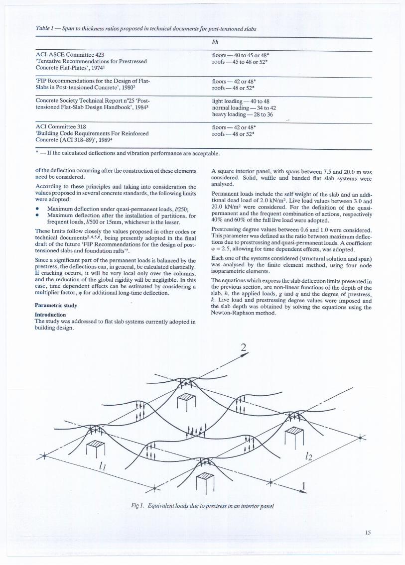
Table 1- Span to thickness ra/iosproposed in technicaldocuments for post-tensioned slabs
l/h
ACI-ASCE Committee 423'Tentative Recommendations for PrestressedConcrete Flat-Plates', 19741
floors - 40 to 45 or 48 *roofs - 45 to 48 or 52 *
'FIP Recommendations for the Design of Flat-Slabs in Post-tensioned Concrete', 19802
floors- 42 or 48*roofs - 48 or 52*
Concrete Society Technical Report n"25 'Post-tensioned Flat-Slab Design Handbook', 19843
light .loading - 40 to 48normalloading - 34 to 42heavy loading - 28 to 36
ACI Committee 318'Building Code Requirements For ReinforcedConcrete (ACI 318-89)', 19894
floors - 42 or 48*roofs - 48 or 52*
* - li the calculated deflections and vibration performance are acceptable.
of the deflection occurring after the construction of these elementsneed be considered.
According to these principIes and taking into consideration thevalues proposed in several concrete standards, the foIlowinglimitswere adopted:
. Maximum deflection under quasi-permanent loads, //250;· Maximum deflection after the installation of partitions, for
frequent loads, 1/500or 15mm, whichever is the lesser.
These limits follow closely the values proposed in other codes ortechnical documents2,4,S,6, being presently adopted in the finaldraft of the future 'FIP Recommendations for the design of post-tensioned slabs and foundation rafts'7.
Since a significant part of the permanent loads is balanced by theprestress, the deflections can, in general, be calculated elastically.li cracking oecurs, it will be very local only over the columns,and the reduction of the global rigidity wiIl be negligible. In thiscase, time dependent effects can be estimated by considering amultiplier factor, 'Pfor additionallong-time deflection.
Parametric studyIntroductionThe study was addressed to flat slab systems currently adopted inbuilding designo
A square interior panel, with spans between 7.5 and 20.0 m wasconsidered. Solid, waffle and banded flat slab systems wereanalysed.
Permanent loads include the self weight of the slab and an addi-tional dead load of 2.0 kN/m2. Live load values between 3.0 and20.0 kN/m2 were considered. For the definition of the quasi-permanent and the frequent combination of actions, respectively40% and 60% of the fulllive load were adopted.
Prestressing degree values between 0.6 and 1.0 were considered.This parameter was defined as the ratio between maximum deflec-tions due to prestressing and quasi-permanent loads. A coefficient'P= 2.5, allowing for time dependent effects, was adopted.
Each one of the systems considered (structural solution and span)was analysed by the finite element method, using four nodeisoparametric elements.
The equations which express the slab deflection limits presented inthe previous section, are non-linear functions of the depth of theslab, h, the applied loads, g and q and the degree of prestress,k. Live load and prestressing degree values were imposed andthe slab depth was obtained by solving the equations using theNewton-Raphson method.
/y
Fig 1. Equivalent loads due to prestress in an interior panel
- ~ --- --
15
--
70IIh
.1=12.5mk=0.6
60
50
~ ~ quasi-pennanentloads (q.p.):a $1/30040
30
(~) =770a
~qp
(~) =920a qp
~ frequentloads: a $ 1/500. 15.mm
g+q
g20I
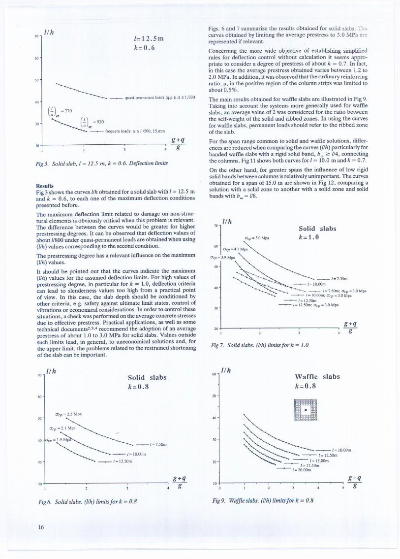
Fig3. Solid slab, 1= 12.5 m, k = 0.6. Deflection limits
ResultsFig 3 shows the curves I/h obtained for a solid slab with I = 12.5 mand k = 0.6, to each one of the maximum deflection conditionspresented before.The maximum deflection limit related to damageon non-struc-tural elements is obviously critical when this problem is relevant.The difference between the curves would be greater for higherprestressing degrees. It can be observed that deflection values ofabout 1/800under quasi-permanent loads are obtained when using(I/h) values corresponding to the second condition.
The prestressing degree has a relevant influence on the maximum(I/h) values.
It should be pointed out that the curves indicate the maxinlum(l/h) values for the assumed deflection limits. For high values ofprestressing degree, in particular for k = 1.0, deflection criteriacan lead to slendemess values too high from a practical pointof view. In this case, the slab depth should be conditioned byother criteria, e.g. safety against ultimate limit states, control ofvibrations or economical considerations. In order to control thesesituations, a check was performed on the average concrete stressesdue to effective prestress. Practical applications, as well as sometechnical documents2.3.4 recommend the adoption of an averageprestress of about 1.0 to 3.0 MPa for solid slabs. Values outsidesuch limits lead, in general, to uneconomical solutions and, forthe upper limit, the problems related to the restrained shorteningof the slab can be important.
70 IIhSolid slabsk=0.8
60
50Gcp = 2.5 Mpa
40
30
20I
g+q
-g
Fig 6. Solid slabs. (I/h) limits for k = 0.8
16
-- ----
Figs. 6 and 7 summarize the results obtained for solid slabs. 'l'hecurves obtained by limiting the average prestress to 3.0 MPa arerepresented if relevant.
Concerning the more wide objective of establishing simplifiedrules for deflection control without calculation it seems appro-priate to consider a degree of prestress of about k = 0.7. In fact,in this case the average prestress obtained varies between 1.2 to2.0 MPa. In addition, it was observed that the ordinary reinforcingratio, p, in the positive region of the column strips was limited toabout 0.5%.
The main results obtained for waffle slabs are illustratedin Fig 9.Taking into account the systems more generally used for waffleslabs, an average value of 2 was considered for the ratio betweenthe self-weight of the solid and ribbed zones. In using the curvesfor waffle slabs, permanent loads should refer to the ribbed zoneofthe slab.
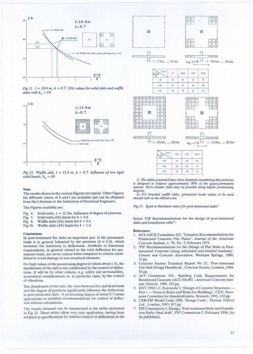
For the span range common to solid and waffle solutions, differ-ences are reduced when comparing the curves (l/h) particularly forbanded waffle slabs with a rigid solid band, b", ~ 1/4, connectingthe columns. Fig 11shows both curves for I = 10.0 m and k = 0.7.On the other hand, for greater spans the influence of low rigidsolid bands between columns is relatively unimportant. The curvesobtained for a span of 15.0 m are shown in Fig 12, comparing asolution with a solid zone to another with a solid zone and solidbands with b.. = 1/8.
7°
1
l/h
C7cp =5.0 Mpa
60 G'p=4.1 Mpa
Gcp = 3.9 Mpa
Solid slabsk= 1.0
50
40~- 1=750m; C7Cp=3.0 Mpa
- 1= 10.oom;Gcp= 3.0Mpa-1=1250m
- 1= 1250m; Gcp= 3.0Mpa30
20I
Fig 7. Solid slabs. (I/h) limits for k = 1.0
60 l/h Waffle slabsk=0.8
50
40
30
20
10o
g+q-g
Fig9. Waffleslabs.(I/h)limitsfor k = 0.8
50lIh
1=10.0mk=O.7
40 ...Ql(2) D 88~
_(2) Waftle slab with a rigid solid band (bw =1/4)
30
20O
Fig 11. 1= 10.0 m, k = 0.7. (l/h) valuesfor solid slabs and waffleslabs with b., = 1/4
40lIh
1=15.0mk=O.7
30
20~c
. EmgT:"':0 DO (;~. . 11I
. ~~]. ~
" ~ 8:;;;
~ -~ ~".....~_Solidzone
g+q-g10
o
Fig 12. Waffle slab, 1 = 15.0 m, k = 0.7. lnfluence of low rigidsolid bands, b., = 1/8
NoteThe results shown in the various Figures are typical. Other Figuresfor different values of k and 1 are available and can be obtainedfrom the Librarian at the Institution of Structural Engineers.
The Figures available are:
Fig 4. Solid slabs, 1 = 12.5m. Influence of degree of prestressFig 5.. Solid slabs (l/h) limits for k = 0.6Fig 8. Waffle slabs (l/h) limits for k =0.6Fig10. Waffleslabs(l/h) limitsfor k = 1.0.
ConclusionsIn post-tensioned fIat slabs an important part of the permanentloads is in general balanced by the prestress (k ~ 0.6), whichincreases the sensitivity to defIections. Aesthetic or functionalrequirements, in general related to the total defIection for per-manent loads, are never critical when compared to criteria estab-lished to avoid damage in non structural elements.
For high values of the prestressing degree (k values about 1.0), theslendemess of the slab is not conditioned by the control of defIec-tions. It will be by other criteria, e.g. safety and serviceability,economical considerations or, in particular cases, by the controlof vibrations.
The slendemess of the slab, the ratio between live and dead loadsand the degree of prestress significantly influence the defIectionsin post-tensioned slabs. A prestressing degree of about 0.7 seemsappropriate to establish recommendations for control of defIec-tion without calculations.
The results obtained can be summarized in the tables presentedin Fig 13. These tables allow very easy application, having beenadopted as specifications for indirect control of deflections in the
---
t ~ tI : 705rn, "'0 1205rn
OOtrlnr'--''--'~
ElEilt
I , IO.Orno'''0 20.Om.
_.J L J i..JL J i..-I i...:.J i J i.
OOOOOOOC][ODOO[JO[][][DO O[J[On r-,r-,r
.1 W fid ~=:!:=J~.',DO LJLJL00 r-,,-.,,.L LJLJ~
ODO[][JOO[JGOOL"J[][J[J[]OC~"~r., "-H.-"r-"'!r r~.,,.
L..ii..';..ii i
E]Oe], , r-,r...,. li II II JI..-''-..
[J[J
lni"1JL_J,-..J,~ ,.-.,:JULJLJ
J[J[JO,r-,,.,:",,.-,
rlnr1..."''''_.1 L
O[]ll[g~~JC
ft""'-' 8 ,-,,-,,,4b(J) <114 I : IO.Orn, "'0 20.0rn-+-+
i) The tables presented have been obtained considering that prestressis designed to balance approximately 70% of the quosi-permanentactions. More slenderslabs may bepossible using higherprestressingdegrees;
ii). For branded waffle slabs, permanent loads values to be usedshould referto theribbedzone.
Fig13. Span to thickness ratiosfor post-tensioned slabs7
future 'FIP Recommendations for the design of post-tensionedslabs and foundation rafts'7.
References1. ACI-ASCE Committee 423, 'Tentative Recommendations for
Prestressed Concrete Flat Plates', Joumal of the AmericanConcrete lnstitute, v. 71, No. 2, February 1974.
2. 'FIP Recommendations for the Design of Flat .Slabs in Post-tensioned Concrete (using unbonded and bonded tendons)',Cement and Concrete Association, Wexham Springs, 1980,21pp.
3. Concrete Society Technical Report No 25, 'Post-tensionedFlat-Slab Design Handbook', ConcreteSociety, London, 1984,43pp.
4. ACI Committee 318, 'Building Code Requirements forReinforced Concrete (ACI 318-89)', American Concrete lnsti-tute, Detroit, 1989,353 pp.
5. ENV 1992-1-1,Eurocode 2, 'Design of Concrete Structures-Part 1- General Rules and Rules for Buildings', CEN, Euro-pean Committee for Standardization, Brussels, 1991,253 pp.
6. CEB-FIP Model Code 1990, 'Design Code', Thomas TelfordLtd., London, 1993,437 pp.
7. FIP Commissión 3, Design, 'Post-tensioned Slabs and Founda-tion Rafts, final draft', FIP Commission3, February 1994, (tobe published).
17
7.5 10,0 15.0 20.0g+q---r- .
1.0 45 42 33 27
2.0 41 34 26 20
3.0 35 29 22 16
10.0 15.0 20.0
1.0 37 29 24
2.0 30 22 17
3.0 25 18 14


![Modelling of Unbonded Post-Tensioned Concrete Slabs Under ... · unbonded post-tensioned slabs. The slabs were designed accord-ing to BS 8110-1 [22] and the Concrete Society Technical](https://img.dokumen.tips/doc/110x75/60f7151a886e554e76513f68/modelling-of-unbonded-post-tensioned-concrete-slabs-under-unbonded-post-tensioned.jpg)