Embed Size (px)
Citation preview
Control DDDDemand Driven Distribution
Installation and operating instructions
GRUNDFOS INSTRUCTIONS
En
glis
h (G
B)
English (GB) Installation and operating instructions
Original installation and operating instructions
These installation and operating instructions describe Grundfos Control DDD.
CONTENTSPage
Use this document in conjunction with these documents:• installation and operating instructions for the pumps• installation and operating instructions for the pressure and
flow sensor • installation and operating instructions for the remote sensor• installation and operating instructions for the CU 354
controller.
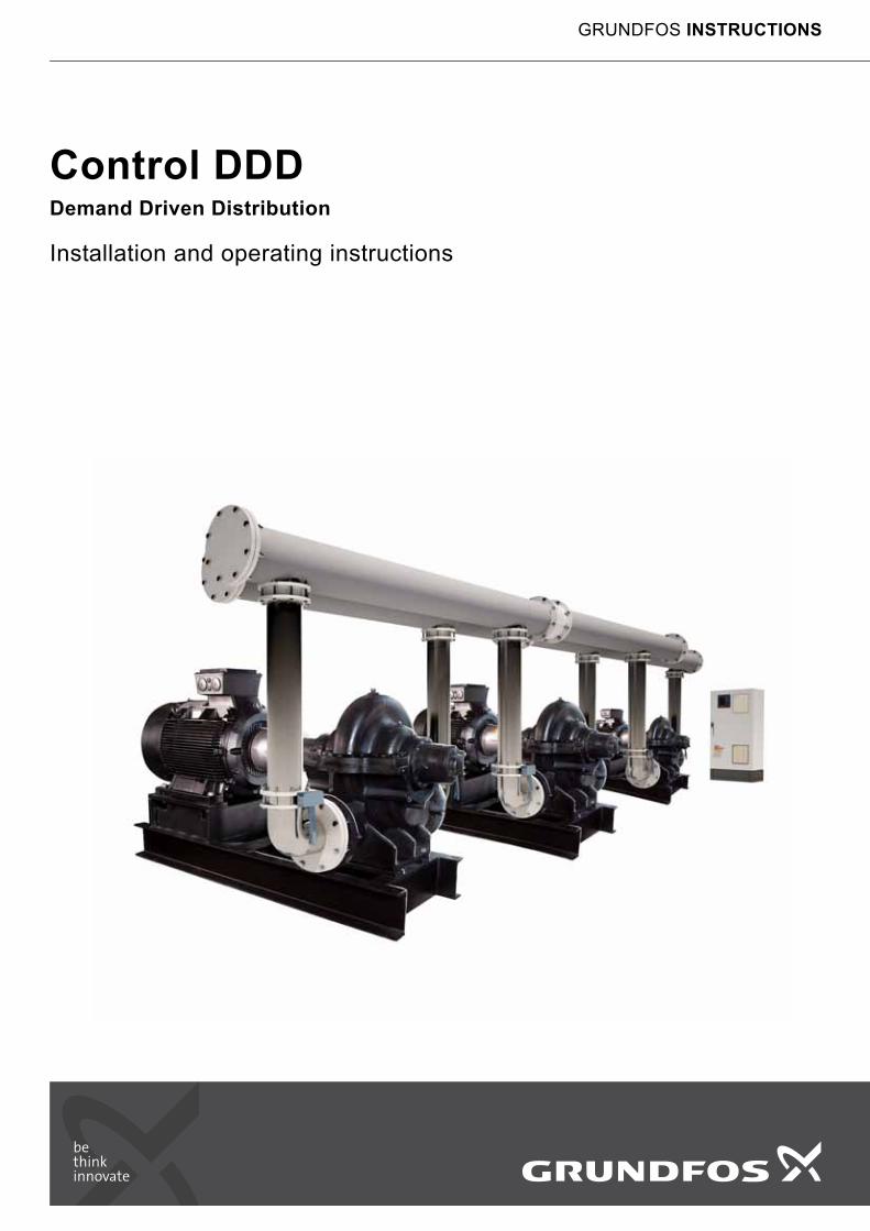
1. General information
1.1 Hazard statements
The symbols and hazard statements below may appear in Grundfos installation and operating instructions, safety instructions and service instructions.
The hazard statements are structured in the following way:
1.2 Notes
The symbols and notes below may appear in Grundfos installation and operating instructions, safety instructions and service instructions.
1. General information 21.1 Hazard statements 21.2 Notes 22. Receiving the product 32.1 Transporting the product 32.2 Lifting the product 33. Installing the product 33.1 Location 33.2 Mechanical installation 33.3 Electrical installation 33.4 Installation of remote sensors 34. Starting up the product 3
5. Operating panel 45.1 Display 45.2 Buttons and indicator lights 56. Product introduction 56.1 Description of functions 66.2 Identification 76.3 Type key 87. Overview of control variants 9
8. Functions 108.1 Tree of functions 108.2 Overview 138.3 Description of functions 158.4 Status (1) 158.5 Operation (2) 208.6 Alarm (3) 228.7 Settings (4) 258.8 Data communication 609. Measuring parameters 639.1 Transmitter types 639.2 Parameter list 6310. Servicing the product 6410.1 Maintaining the product 6411. Taking the product out of operation 64
12. Fault finding 64
13. Technical data 6513.1 Altitude above sea level 6513.2 Temperature 6513.3 Relative humidity 6514. Electrical data 65
15. Further product information 65
16. Disposing of the product 65
Read this document before installing the product. Installation and operation must comply with local regulations and accepted codes of good practice.
DANGER
Indicates a hazardous situation which, if not avoided, will result in death or serious personal injury.
WARNING
Indicates a hazardous situation which, if not avoided, could result in death or serious personal injury.
CAUTION
Indicates a hazardous situation which, if not avoided, could result in minor or moderate personal injury.
SIGNAL WORD
Description of hazard
Consequence of ignoring the warning.- Action to avoid the hazard.
Observe these instructions for explosion-proof products.
A blue or grey circle with a white graphical symbol indicates that an action must be taken.
A red or grey circle with a diagonal bar, possibly with a black graphical symbol, indicates that an action must not be taken or must be stopped.
If these instructions are not observed, it may result in malfunction or damage to the equipment.
Tips and advice that make the work easier.
2
En
gli
sh
(G
B)
2. Receiving the product2.1 Transporting the product
Depending on size, the control cabinet is supplied in an open wooden box or wooden/cardboard box designed for transport by forklift truck or a similar vehicle.
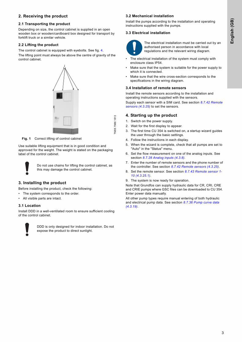
2.2 Lifting the product
The control cabinet is equipped with eyebolts. See fig. 4.The lifting point must always be above the centre of gravity of the control cabinet.
Fig. 1 Correct lifting of control cabinet
Use suitable lifting equipment that is in good condition and approved for the weight. The weight is stated on the packaging label of the control cabinet.
3. Installing the productBefore installing the product, check the following:• The system corresponds to the order.• All visible parts are intact.
3.1 Location
Install DDD in a well-ventilated room to ensure sufficient cooling of the control cabinet.
3.2 Mechanical installation
Install the pumps according to the installation and operating instructions supplied with the pumps.
3.3 Electrical installation
• The electrical installation of the system must comply with enclosure class IP54.
• Make sure that the system is suitable for the power supply to which it is connected.
• Make sure that the wire cross-section corresponds to the specifications in the wiring diagram.
3.4 Installation of remote sensors
Install the remote sensors according to the installation and operating instructions supplied with the sensors.Supply each sensor with a SIM card. See section 8.7.42 Remote sensors (4.3.25) to set the sensors.
4. Starting up the product1. Switch on the power supply.2. Wait for the first display to appear.3. The first time CU 354 is switched on, a startup wizard guides
the user through the basic settings.4. Follow the instructions in each display.5. When the wizard is complete, check that all pumps are set to
"Auto" in the "Status" menu.6. Set the flow measurement on one of the analog inputs. See
section 8.7.28 Analog inputs (4.3.8).7. Enter the number of remote sensors and the phone number of
the controller. See section 8.7.42 Remote sensors (4.3.25).8. Set the remote sensor. See section 8.7.43 Remote sensor 1-
10 (4.3.25.1).9. The system is now ready for operation.Note that Grundfos can supply hydraulic data for CR, CRI, CRE and CRIE pumps where GSC files can be downloaded to CU 354. Enter power data manually.All other pump types require manual entering of both hydraulic and electrical pump data. See section 8.7.36 Pump curve data (4.3.19).
TM05
798
8 18
13
Do not use chains for lifting the control cabinet, as this may damage the control cabinet.
DDD is only designed for indoor installation. Do not expose the product to direct sunlight.
The electrical installation must be carried out by an authorised person in accordance with local regulations and the relevant wiring diagram.
3
En
glis
h (G
B)
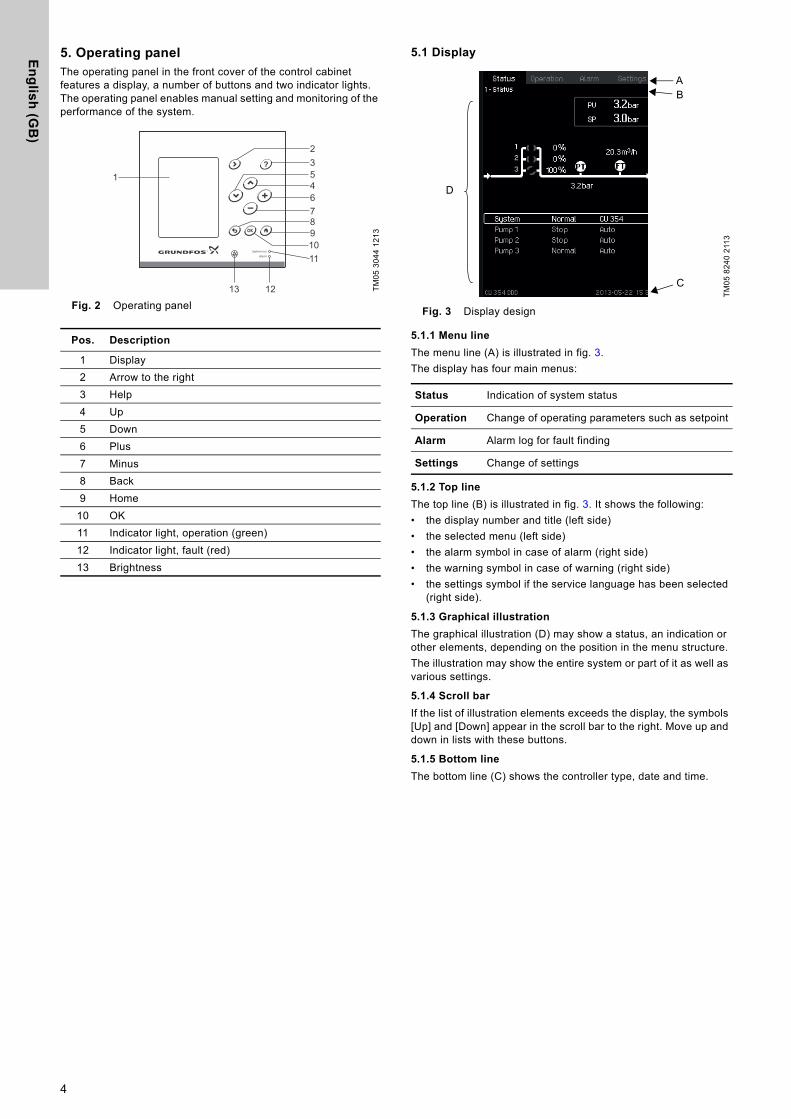
5. Operating panelThe operating panel in the front cover of the control cabinet features a display, a number of buttons and two indicator lights. The operating panel enables manual setting and monitoring of the performance of the system.
Fig. 2 Operating panel
5.1 Display
Fig. 3 Display design
5.1.1 Menu line
The menu line (A) is illustrated in fig. 3.The display has four main menus:
5.1.2 Top line
The top line (B) is illustrated in fig. 3. It shows the following:• the display number and title (left side)• the selected menu (left side)• the alarm symbol in case of alarm (right side) • the warning symbol in case of warning (right side)• the settings symbol if the service language has been selected
(right side).
5.1.3 Graphical illustration
The graphical illustration (D) may show a status, an indication or other elements, depending on the position in the menu structure.The illustration may show the entire system or part of it as well as various settings.
5.1.4 Scroll bar
If the list of illustration elements exceeds the display, the symbols [Up] and [Down] appear in the scroll bar to the right. Move up and down in lists with these buttons.
5.1.5 Bottom line
The bottom line (C) shows the controller type, date and time.
TM05
304
4 12
13
Pos. Description
1 Display2 Arrow to the right3 Help4 Up5 Down6 Plus7 Minus8 Back9 Home
10 OK11 Indicator light, operation (green)12 Indicator light, fault (red)13 Brightness
1
111098764532
1213 TM05
824
0 21
13
Status Indication of system status
Operation Change of operating parameters such as setpoint
Alarm Alarm log for fault finding
Settings Change of settings
AB
D
C
4
En
gli
sh
(G
B)
5.2 Buttons and indicator lights
The buttons (2 to 10 in fig. 2) on CU 354 are active when they are lit.
5.2.1 Arrow to the right (2)
Press [Right] to go to the next menu in the menu structure. If you press [Right] when menu "Settings" is highlighted, you will go to menu "Status".
5.2.2 Help (3)
When [?] is lit, a help text applying to the display will appear if you press the button.Close the text by pressing [Back].
5.2.3 Up and down (4 and 5)
Move up and down in lists with the [Down] and [Up] buttons.You can select a text with [OK] when it is in a box.If a text is marked and you press [Up], the text above will be marked. If you press [Down], the text below will be marked.If you press [Down] in the last line in the list, the first line will be marked.If you press [Up] in the first line in the list, the last line will be marked.
5.2.4 Plus and minus (6 and 7)
Increase and reduce a value with [+] and [-]. Save with [OK].
5.2.5 Back (8)
Press [Back] to go one display back in the menu. If you have changed a value and press [Back], the new value will not be saved. See also section 5.2.7 OK (10).If you press [OK] before pressing [Back], the new value will be saved. See also section 5.2.7 OK (10).
5.2.6 Home (9)
Press [Home] to return to the menu "Status".
5.2.7 OK (10)
Use the button as an enter button.The button is also used to start the setting of a value. If you have changed a value, you must press [OK] to save the change.
5.2.8 Indicator lights (11 and 12)
The operating panel incorporates a green and red indicator light.The green indicator light will be on when the system is in operation and flash when the system has been set to stop.The red indicator light will be on if there is an alarm or a warning. The fault can be identified from the alarm list.
5.2.9 Brightness (13)
You can change the brightness in the display with this button:1. Press [Brightness].2. Adjust the brightness with [+] and [-].
5.2.10 Back light
If no button is touched for 15 minutes, the back light of the display is dimmed, and the first display in the "Status" menu appears. Press any button to re-activate the back light.
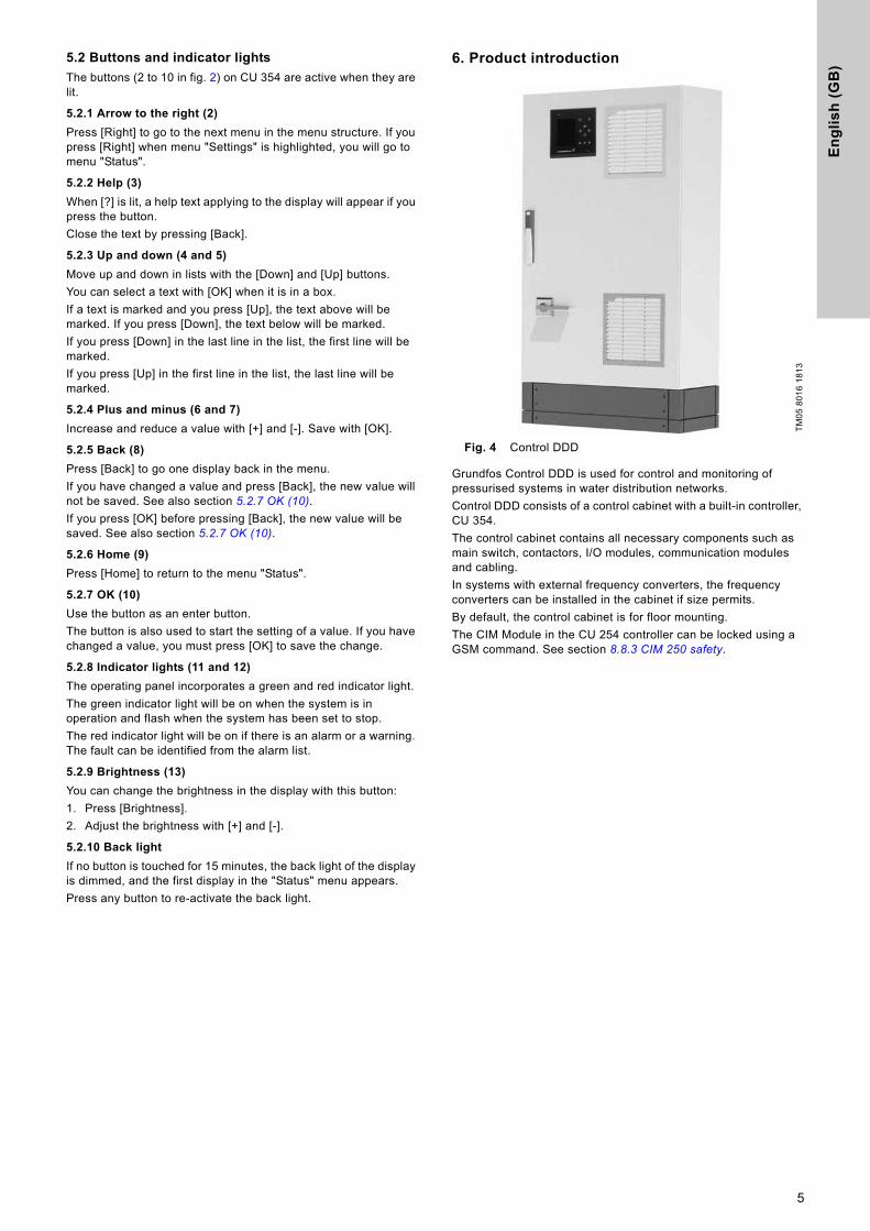
6. Product introduction
Fig. 4 Control DDD
Grundfos Control DDD is used for control and monitoring of pressurised systems in water distribution networks.Control DDD consists of a control cabinet with a built-in controller, CU 354.The control cabinet contains all necessary components such as main switch, contactors, I/O modules, communication modules and cabling.In systems with external frequency converters, the frequency converters can be installed in the cabinet if size permits. By default, the control cabinet is for floor mounting.The CIM Module in the CU 254 controller can be locked using a GSM command. See section 8.8.3 CIM 250 safety.
TM05
801
6 18
13
5
En
glis
h (G
B)
6.1 Description of functions
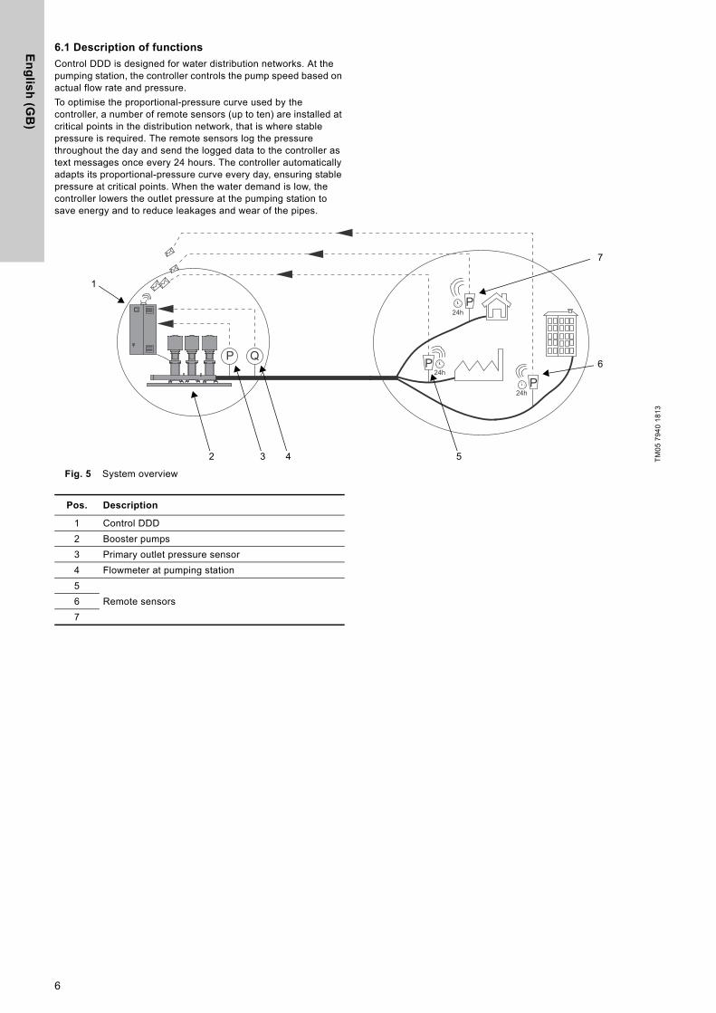
Control DDD is designed for water distribution networks. At the pumping station, the controller controls the pump speed based on actual flow rate and pressure.To optimise the proportional-pressure curve used by the controller, a number of remote sensors (up to ten) are installed at critical points in the distribution network, that is where stable pressure is required. The remote sensors log the pressure throughout the day and send the logged data to the controller as text messages once every 24 hours. The controller automatically adapts its proportional-pressure curve every day, ensuring stable pressure at critical points. When the water demand is low, the controller lowers the outlet pressure at the pumping station to save energy and to reduce leakages and wear of the pipes.
Fig. 5 System overview
TM05
794
0 18
13
P
PP
P Q
24h
24h
24h
1
432 5
6
7
Pos. Description
1 Control DDD2 Booster pumps3 Primary outlet pressure sensor4 Flowmeter at pumping station5
Remote sensors67
6
En
gli
sh
(G
B)
6.1.1 Pumps
Control DDD is designed for controlling pumps for water supply.
6.1.2 Control variant
Control DDD is divided into three groups based on control variant:
See also section 7. Overview of control variants.
6.1.3 Remote sensor
The remote sensor logs the pressure in the water distribution network at the end user or critical point. Every 24 hours the logged data are sent as a text message to the controller via the GSM network. The data are combined with the data from the other remote sensors to form a model of the distribution network. The sensors can be set to give a warning if the pressure drops below a user-defined limit.See also installation and operating instructions for the Sofrel LS42 logger and the XiLog sensor.
Fig. 6 Sofrel LS42 Logger and XiLog sensor
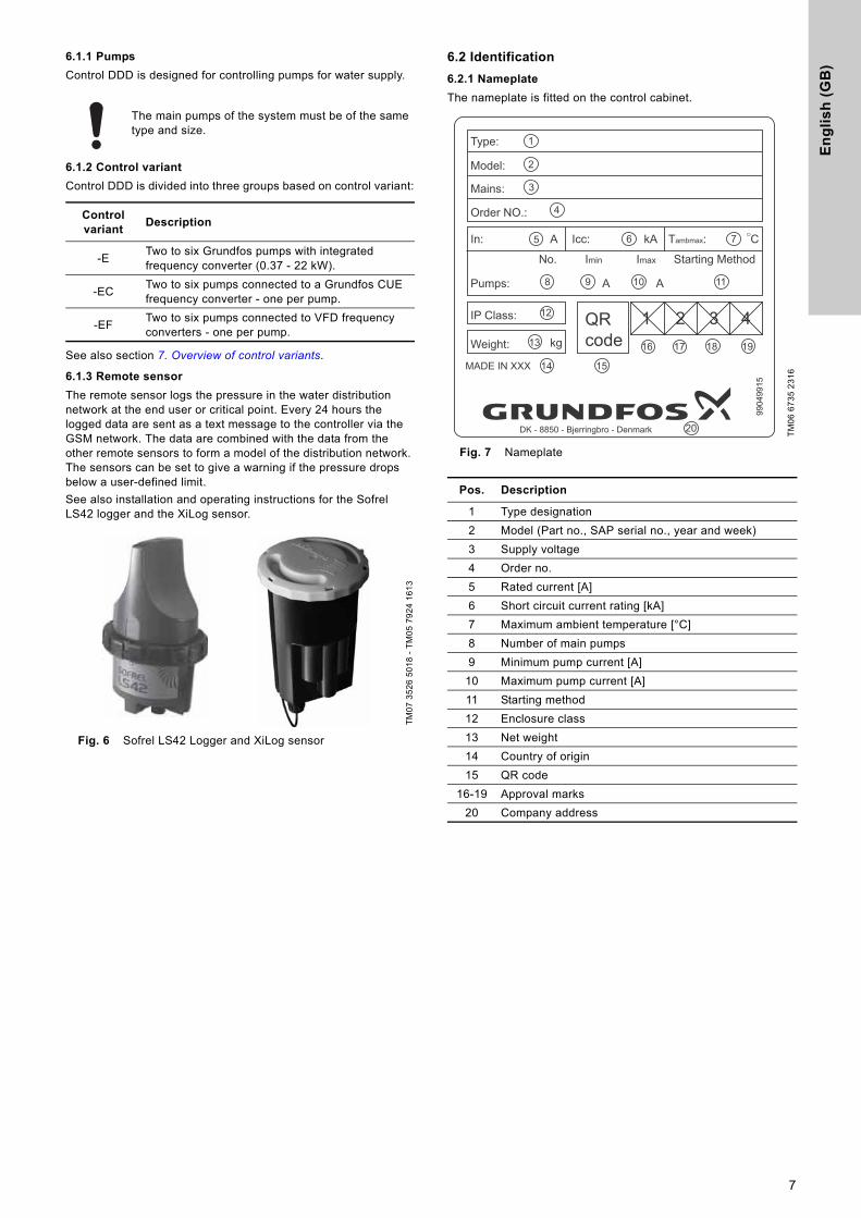
6.2 Identification
6.2.1 Nameplate
The nameplate is fitted on the control cabinet.
Fig. 7 Nameplate
The main pumps of the system must be of the same type and size.
Control variant
Description
-E Two to six Grundfos pumps with integrated frequency converter (0.37 - 22 kW).
-EC Two to six pumps connected to a Grundfos CUE frequency converter - one per pump.
-EF Two to six pumps connected to VFD frequency converters - one per pump.
TM07
352
6 50
18 -
TM05
792
4 16
13
TM06
673
5 23
16
Pos. Description
1 Type designation2 Model (Part no., SAP serial no., year and week)3 Supply voltage4 Order no.5 Rated current [A]6 Short circuit current rating [kA]7 Maximum ambient temperature [°C]8 Number of main pumps9 Minimum pump current [A]
10 Maximum pump current [A]11 Starting method12 Enclosure class13 Net weight 14 Country of origin15 QR code
16-19 Approval marks20 Company address
9904
9915
Type:
Model:
Mains:
Order NO.:
In: Icc: kA
kg
C
Starting Method
Pumps:
IP Class:
Weight:
1
2
3
4
5 6 7
8 9 10 11
12
13
14 15
16 17 18 19
20
QRcode
MADE IN XXX
No. Imin Imax
A
A
A
Tambmax:
1 2 3 4
DK - 8850 - Bjerringbro - Denmark
7
En
glis
h (G
B)
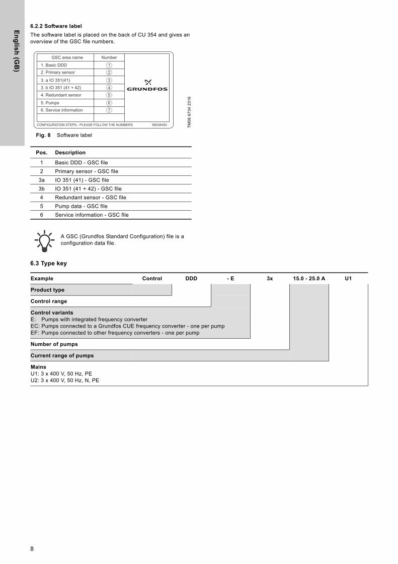
6.2.2 Software label
The software label is placed on the back of CU 354 and gives an overview of the GSC file numbers.
Fig. 8 Software label
6.3 Type key
TM06
673
4 23
16
Pos. Description
1 Basic DDD - GSC file2 Primary sensor - GSC file
3a IO 351 (41) - GSC file3b IO 351 (41 + 42) - GSC file4 Redundant sensor - GSC file5 Pump data - GSC file6 Service information - GSC file
A GSC (Grundfos Standard Configuration) file is a configuration data file.
GSC area name
1. Basic DDD2. Primary sensor
3. a IO 351(41)
3. b IO 351 (41 + 42)
4. Redundant sensor
5. Pumps6. Service information
Number
CONFIGURATION STEPS - PLEASE FOLLOW THE NUMBERS 99038450
1
2
3
4
5
6
7
Example Control DDD - E 3x 15.0 - 25.0 A U1
Product type
Control range
Control variantsE: Pumps with integrated frequency converterEC: Pumps connected to a Grundfos CUE frequency converter - one per pumpEF: Pumps connected to other frequency converters - one per pump
Number of pumps
Current range of pumps
MainsU1: 3 x 400 V, 50 Hz, PEU2: 3 x 400 V, 50 Hz, N, PE
8
En
gli
sh
(G
B)
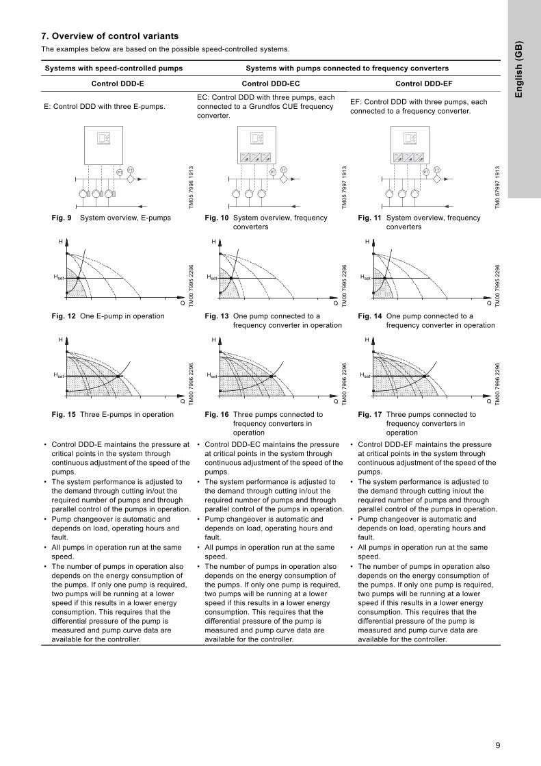
7. Overview of control variantsThe examples below are based on the possible speed-controlled systems.
Systems with speed-controlled pumps Systems with pumps connected to frequency converters
Control DDD-E Control DDD-EC Control DDD-EF
E: Control DDD with three E-pumps.EC: Control DDD with three pumps, each connected to a Grundfos CUE frequency converter.
EF: Control DDD with three pumps, each connected to a frequency converter.
TM05
799
8 19
13
TM05
799
7 19
13
TM0
5799
7 19
13
Fig. 9 System overview, E-pumps Fig. 10 System overview, frequency converters
Fig. 11 System overview, frequency converters
TM00
799
5 22
96
TM00
799
5 22
96
TM00
799
5 22
96
Fig. 12 One E-pump in operation Fig. 13 One pump connected to a frequency converter in operation
Fig. 14 One pump connected to a frequency converter in operation
TM00
799
6 22
96
TM00
799
6 22
96
TM00
799
6 22
96
Fig. 15 Three E-pumps in operation Fig. 16 Three pumps connected to frequency converters in operation
Fig. 17 Three pumps connected to frequency converters in operation
• Control DDD-E maintains the pressure at critical points in the system through continuous adjustment of the speed of the pumps.
• The system performance is adjusted to the demand through cutting in/out the required number of pumps and through parallel control of the pumps in operation.
• Pump changeover is automatic and depends on load, operating hours and fault.
• All pumps in operation run at the same speed.
• The number of pumps in operation also depends on the energy consumption of the pumps. If only one pump is required, two pumps will be running at a lower speed if this results in a lower energy consumption. This requires that the differential pressure of the pump is measured and pump curve data are available for the controller.
• Control DDD-EC maintains the pressure at critical points in the system through continuous adjustment of the speed of the pumps.
• The system performance is adjusted to the demand through cutting in/out the required number of pumps and through parallel control of the pumps in operation.
• Pump changeover is automatic and depends on load, operating hours and fault.
• All pumps in operation run at the same speed.
• The number of pumps in operation also depends on the energy consumption of the pumps. If only one pump is required, two pumps will be running at a lower speed if this results in a lower energy consumption. This requires that the differential pressure of the pump is measured and pump curve data are available for the controller.
• Control DDD-EF maintains the pressure at critical points in the system through continuous adjustment of the speed of the pumps.
• The system performance is adjusted to the demand through cutting in/out the required number of pumps and through parallel control of the pumps in operation.
• Pump changeover is automatic and depends on load, operating hours and fault.
• All pumps in operation run at the same speed.
• The number of pumps in operation also depends on the energy consumption of the pumps. If only one pump is required, two pumps will be running at a lower speed if this results in a lower energy consumption. This requires that the differential pressure of the pump is measured and pump curve data are available for the controller.
PT FT PT FT PT FT
Q
H
Hset
Q
H
Hset
Q
H
Hset
Q
H
Hset
Q
H
Hset
Q
H
Hset
9
En
glis
h (G
B)
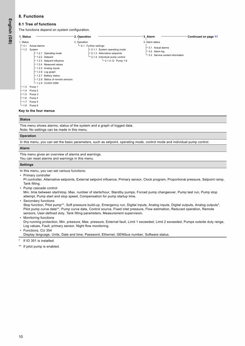
8. Functions
8.1 Tree of functions
The functions depend on system configuration.
Key to the four menus
* If IO 351 is installed.
** If pilot pump is enabled.
1. Status 2. Operation 3. Alarm Continued on page 11
1. Status 2. Operation 3. Alarm status3.1 Actual alarms 2.1 Further settings
3.1 Actual alarms1.2 System 2.1.1 System operating mode
3.2 Alarm log1.2.1 Operating mode 2.1.3 Alternative setpoints
3.3 Service contact information1.2.2 Setpoint 2.1.4 Individual pump control1.2.3 Setpoint influence 2.1.4.12 Pump 1-61.2.4 Measured values1.2.5 Analog inputs1.2.6 Log graph1.2.7 Battery status1.2.8 Status of remote sensors1.2.9 CU354 GSM
1.3 Pump 11.4 Pump 21.5 Pump 31.6 Pump 41.7 Pump 51.8 Pump 6
Status
This menu shows alarms, status of the system and a graph of logged data.Note: No settings can be made in this menu.
Operation
In this menu, you can set the basic parameters, such as setpoint, operating mode, control mode and individual pump control.
Alarm
This menu gives an overview of alarms and warnings.You can reset alarms and warnings in this menu.
Settings
In this menu, you can set various functions:• Primary controller
PI controller, Alternative setpoints, External setpoint influence, Primary sensor, Clock program, Proportional pressure, Setpoint ramp, Tank filling.
• Pump cascade controlMin. time between start/stop, Max. number of starts/hour, Standby pumps, Forced pump changeover, Pump test run, Pump stop attempt, Pump start and stop speed, Compensation for pump startup time.
• Secondary functionsStop function, Pilot pump**, Soft pressure build-up, Emergency run, Digital inputs, Analog inputs, Digital outputs, Analog outputs*, Pilot pump curve data**, Pump curve data, Control source, Fixed inlet pressure, Flow estimation, Reduced operation, Remote sensors, User-defined duty, Tank filling parameters, Measurement supervision.
• Monitoring functionsDry-running protection, Min. pressure, Max. pressure, External fault, Limit 1 exceeded, Limit 2 exceeded, Pumps outside duty range, Log values, Fault, primary sensor, Night flow monitoring.
• Functions, CU 354Display language, Units, Date and time, Password, Ethernet, GENIbus number, Software status.
10
En
gli
sh
(G
B)
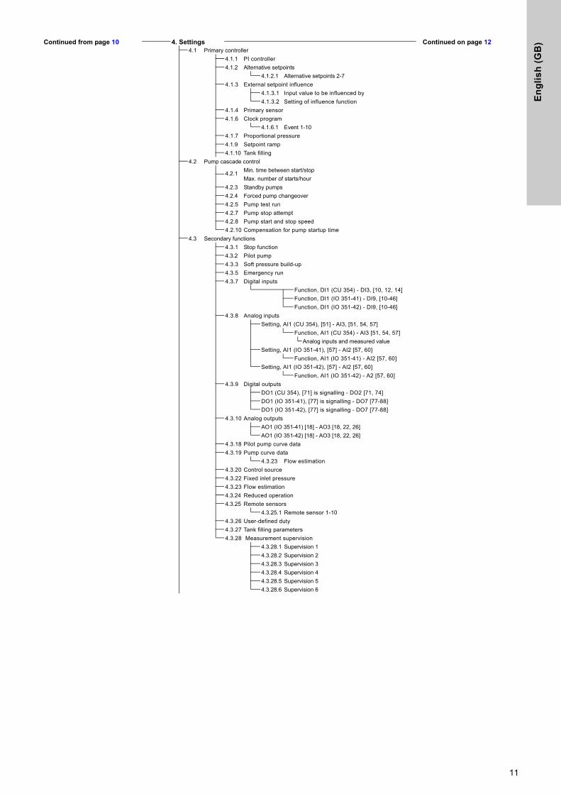
Continued from page 10 4. Settings Continued on page 124.1 Primary controller4.1.1 PI controller4.1.2 Alternative setpoints
4.1.2.1 Alternative setpoints 2-74.1.3 External setpoint influence
4.1.3.1 Input value to be influenced by4.1.3.2 Setting of influence function
4.1.4 Primary sensor4.1.6 Clock program
4.1.6.1 Event 1-104.1.7 Proportional pressure4.1.9 Setpoint ramp 4.1.10 Tank filling
4.2 Pump cascade control
4.2.1 Min. time between start/stopMax. number of starts/hour
4.2.3 Standby pumps4.2.4 Forced pump changeover4.2.5 Pump test run4.2.7 Pump stop attempt4.2.8 Pump start and stop speed4.2.10 Compensation for pump startup time
4.3 Secondary functions4.3.1 Stop function4.3.2 Pilot pump4.3.3 Soft pressure build-up4.3.5 Emergency run4.3.7 Digital inputs
Function, DI1 (CU 354) - DI3, [10, 12, 14]Function, DI1 (IO 351-41) - DI9, [10-46]Function, DI1 (IO 351-42) - DI9, [10-46]
4.3.8 Analog inputsSetting, AI1 (CU 354), [51] - AI3, [51, 54, 57]
Function, AI1 (CU 354) - AI3 [51, 54, 57]Analog inputs and measured value
Setting, AI1 (IO 351-41), [57] - AI2 [57, 60]Function, AI1 (IO 351-41) - AI2 [57, 60]
Setting, AI1 (IO 351-42), [57] - AI2 [57, 60]Function, AI1 (IO 351-42) - A2 [57, 60]
4.3.9 Digital outputsDO1 (CU 354), [71] is signalling - DO2 [71, 74]DO1 (IO 351-41), [77] is signalling - DO7 [77-88]DO1 (IO 351-42), [77] is signalling - DO7 [77-88]
4.3.10 Analog outputsAO1 (IO 351-41) [18] - AO3 [18, 22, 26] AO1 (IO 351-42) [18] - AO3 [18, 22, 26]
4.3.18 Pilot pump curve data4.3.19 Pump curve data
4.3.23 Flow estimation4.3.20 Control source4.3.22 Fixed inlet pressure4.3.23 Flow estimation 4.3.24 Reduced operation4.3.25 Remote sensors
4.3.25.1 Remote sensor 1-104.3.26 User-defined duty 4.3.27 Tank filling parameters4.3.28 Measurement supervision
4.3.28.1 Supervision 14.3.28.2 Supervision 24.3.28.3 Supervision 34.3.28.4 Supervision 44.3.28.5 Supervision 54.3.28.6 Supervision 6
11
En
glis
h (G
B)
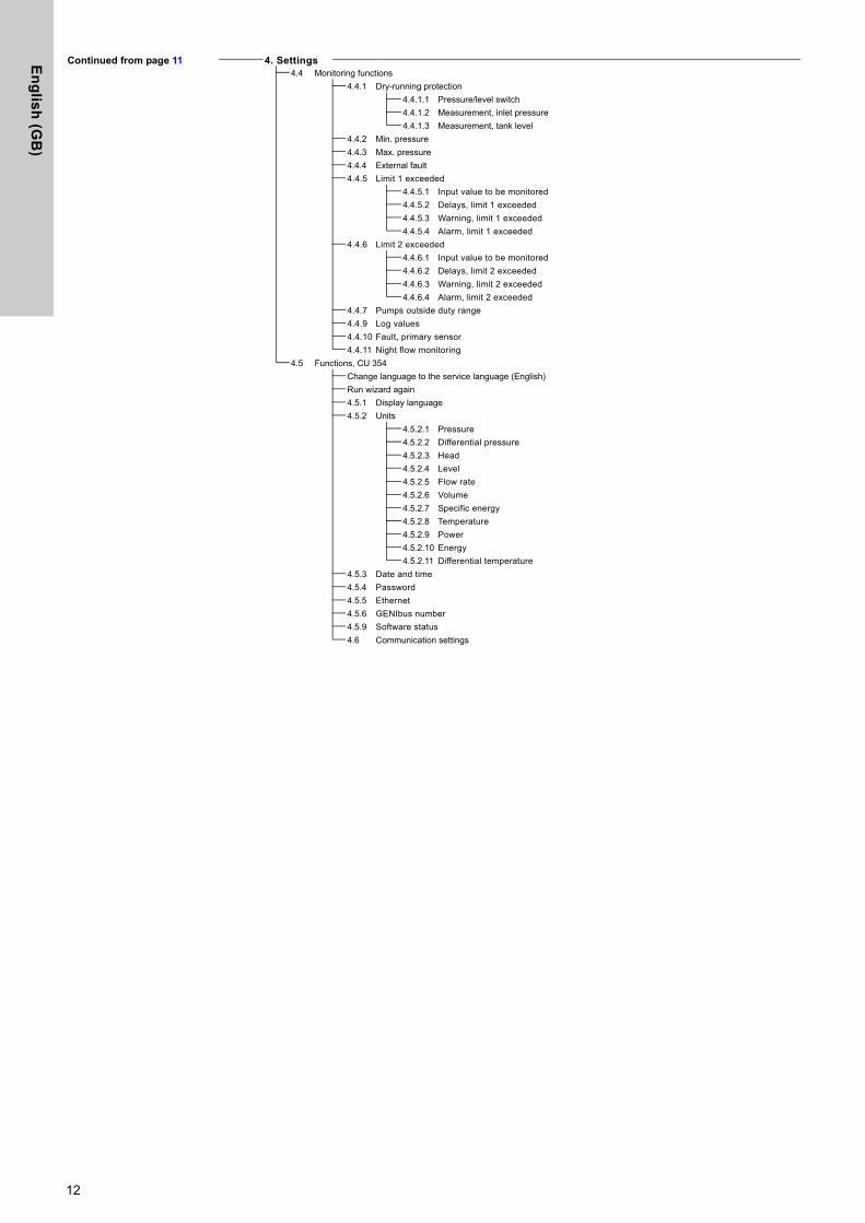
Continued from page 11 4. Settings4.4 Monitoring functions
4.4.1 Dry-running protection4.4.1.1 Pressure/level switch4.4.1.2 Measurement, inlet pressure4.4.1.3 Measurement, tank level
4.4.2 Min. pressure4.4.3 Max. pressure4.4.4 External fault4.4.5 Limit 1 exceeded
4.4.5.1 Input value to be monitored4.4.5.2 Delays, limit 1 exceeded4.4.5.3 Warning, limit 1 exceeded4.4.5.4 Alarm, limit 1 exceeded
4.4.6 Limit 2 exceeded4.4.6.1 Input value to be monitored4.4.6.2 Delays, limit 2 exceeded4.4.6.3 Warning, limit 2 exceeded4.4.6.4 Alarm, limit 2 exceeded
4.4.7 Pumps outside duty range4.4.9 Log values4.4.10 Fault, primary sensor4.4.11 Night flow monitoring
4.5 Functions, CU 354Change language to the service language (English)Run wizard again4.5.1 Display language4.5.2 Units
4.5.2.1 Pressure4.5.2.2 Differential pressure4.5.2.3 Head4.5.2.4 Level4.5.2.5 Flow rate4.5.2.6 Volume4.5.2.7 Specific energy4.5.2.8 Temperature4.5.2.9 Power4.5.2.10 Energy4.5.2.11 Differential temperature
4.5.3 Date and time4.5.4 Password4.5.5 Ethernet4.5.6 GENIbus number4.5.9 Software status4.6 Communication settings
12
En
gli
sh
(G
B)
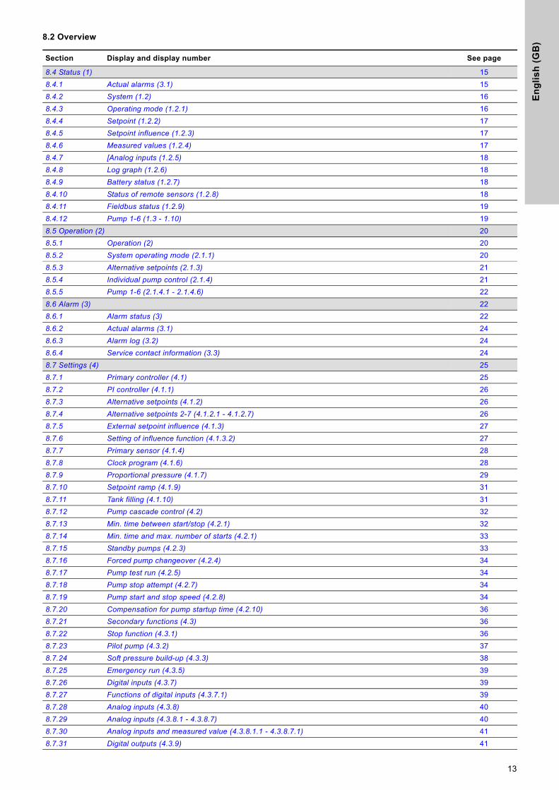
8.2 Overview
Section Display and display number See page
8.4 Status (1) 158.4.1 Actual alarms (3.1) 158.4.2 System (1.2) 168.4.3 Operating mode (1.2.1) 168.4.4 Setpoint (1.2.2) 178.4.5 Setpoint influence (1.2.3) 178.4.6 Measured values (1.2.4) 178.4.7 [Analog inputs (1.2.5) 188.4.8 Log graph (1.2.6) 188.4.9 Battery status (1.2.7) 188.4.10 Status of remote sensors (1.2.8) 188.4.11 Fieldbus status (1.2.9) 198.4.12 Pump 1-6 (1.3 - 1.10) 198.5 Operation (2) 208.5.1 Operation (2) 208.5.2 System operating mode (2.1.1) 208.5.3 Alternative setpoints (2.1.3) 218.5.4 Individual pump control (2.1.4) 218.5.5 Pump 1-6 (2.1.4.1 - 2.1.4.6) 228.6 Alarm (3) 228.6.1 Alarm status (3) 228.6.2 Actual alarms (3.1) 248.6.3 Alarm log (3.2) 248.6.4 Service contact information (3.3) 248.7 Settings (4) 258.7.1 Primary controller (4.1) 258.7.2 PI controller (4.1.1) 268.7.3 Alternative setpoints (4.1.2) 268.7.4 Alternative setpoints 2-7 (4.1.2.1 - 4.1.2.7) 268.7.5 External setpoint influence (4.1.3) 278.7.6 Setting of influence function (4.1.3.2) 278.7.7 Primary sensor (4.1.4) 288.7.8 Clock program (4.1.6) 288.7.9 Proportional pressure (4.1.7) 298.7.10 Setpoint ramp (4.1.9) 318.7.11 Tank filling (4.1.10) 318.7.12 Pump cascade control (4.2) 328.7.13 Min. time between start/stop (4.2.1) 328.7.14 Min. time and max. number of starts (4.2.1) 338.7.15 Standby pumps (4.2.3) 338.7.16 Forced pump changeover (4.2.4) 348.7.17 Pump test run (4.2.5) 348.7.18 Pump stop attempt (4.2.7) 348.7.19 Pump start and stop speed (4.2.8) 348.7.20 Compensation for pump startup time (4.2.10) 368.7.21 Secondary functions (4.3) 368.7.22 Stop function (4.3.1) 368.7.23 Pilot pump (4.3.2) 378.7.24 Soft pressure build-up (4.3.3) 388.7.25 Emergency run (4.3.5) 398.7.26 Digital inputs (4.3.7) 398.7.27 Functions of digital inputs (4.3.7.1) 398.7.28 Analog inputs (4.3.8) 408.7.29 Analog inputs (4.3.8.1 - 4.3.8.7) 408.7.30 Analog inputs and measured value (4.3.8.1.1 - 4.3.8.7.1) 418.7.31 Digital outputs (4.3.9) 41
13
En
glis
h (G
B)
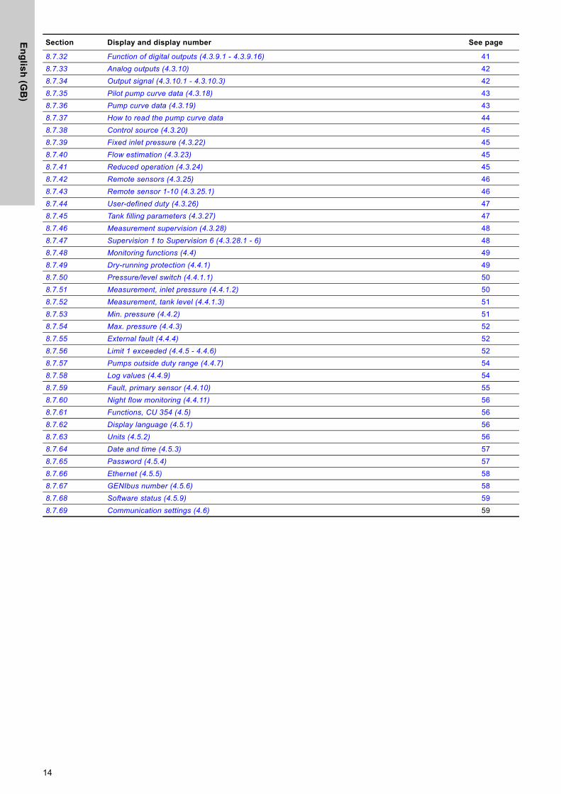
8.7.32 Function of digital outputs (4.3.9.1 - 4.3.9.16) 418.7.33 Analog outputs (4.3.10) 428.7.34 Output signal (4.3.10.1 - 4.3.10.3) 428.7.35 Pilot pump curve data (4.3.18) 438.7.36 Pump curve data (4.3.19) 438.7.37 How to read the pump curve data 448.7.38 Control source (4.3.20) 458.7.39 Fixed inlet pressure (4.3.22) 458.7.40 Flow estimation (4.3.23) 458.7.41 Reduced operation (4.3.24) 458.7.42 Remote sensors (4.3.25) 468.7.43 Remote sensor 1-10 (4.3.25.1) 468.7.44 User-defined duty (4.3.26) 478.7.45 Tank filling parameters (4.3.27) 478.7.46 Measurement supervision (4.3.28) 488.7.47 Supervision 1 to Supervision 6 (4.3.28.1 - 6) 488.7.48 Monitoring functions (4.4) 498.7.49 Dry-running protection (4.4.1) 498.7.50 Pressure/level switch (4.4.1.1) 508.7.51 Measurement, inlet pressure (4.4.1.2) 508.7.52 Measurement, tank level (4.4.1.3) 518.7.53 Min. pressure (4.4.2) 518.7.54 Max. pressure (4.4.3) 528.7.55 External fault (4.4.4) 528.7.56 Limit 1 exceeded (4.4.5 - 4.4.6) 528.7.57 Pumps outside duty range (4.4.7) 548.7.58 Log values (4.4.9) 548.7.59 Fault, primary sensor (4.4.10) 558.7.60 Night flow monitoring (4.4.11) 568.7.61 Functions, CU 354 (4.5) 568.7.62 Display language (4.5.1) 568.7.63 Units (4.5.2) 568.7.64 Date and time (4.5.3) 578.7.65 Password (4.5.4) 578.7.66 Ethernet (4.5.5) 588.7.67 GENIbus number (4.5.6) 588.7.68 Software status (4.5.9) 598.7.69 Communication settings (4.6) 59
Section Display and display number See page
14
En
gli
sh
(G
B)
8.3 Description of functions
The description of functions is based on the four main menus of CU 354:• Status• Operation• Alarm• Settings.The functions apply to all control variants unless otherwise stated.
8.4 Status (1)
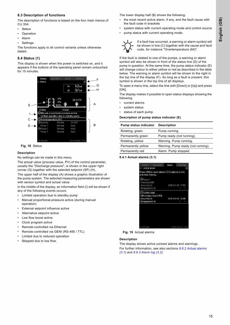
This display is shown when the power is switched on, and it appears if the buttons of the operating panel remain untouched for 15 minutes.
Fig. 18 Status
Description
No settings can be made in this menu.The actual value (process value, PV) of the control parameter, usually the "Discharge pressure", is shown in the upper right corner (G) together with the selected setpoint (SP) (H).The upper half of the display (A) shows a graphic illustration of the pump system. The selected measuring parameters are shown with sensor symbol and actual value.In the middle of the display, an information field (I) will be shown if any of the following events occurs:• Limited operation due to standby pump• Manual proportional-pressure active (during manual
operation)• External setpoint influence active• Alternative setpoint active• Low flow boost active• Clock program active• Remote-controlled via Ethernet• Remote-controlled via GENI (RS-485 / TTL)• Limited due to reduced operation• Stopped due to low flow.
The lower display half (B) shows the following:• the most recent active alarm, if any, and the fault cause with
the fault code in brackets• system status with current operating mode and control source• pump status with current operating mode.
If the fault is related to one of the pumps, a warning or alarm symbol will also be shown in front of the status line (D) of the pump in question. At the same time, the pump status indicator (E) will change colour to either yellow or red as described in the table below. The warning or alarm symbol will be shown to the right in the top line of the display (F). As long as a fault is present, this symbol is shown in the top line of all displays.To open a menu line, select the line with [Down] or [Up] and press [OK].The display makes it possible to open status displays showing the following:• current alarms• system status• status of each pump.
Description of pump status indicator (E)
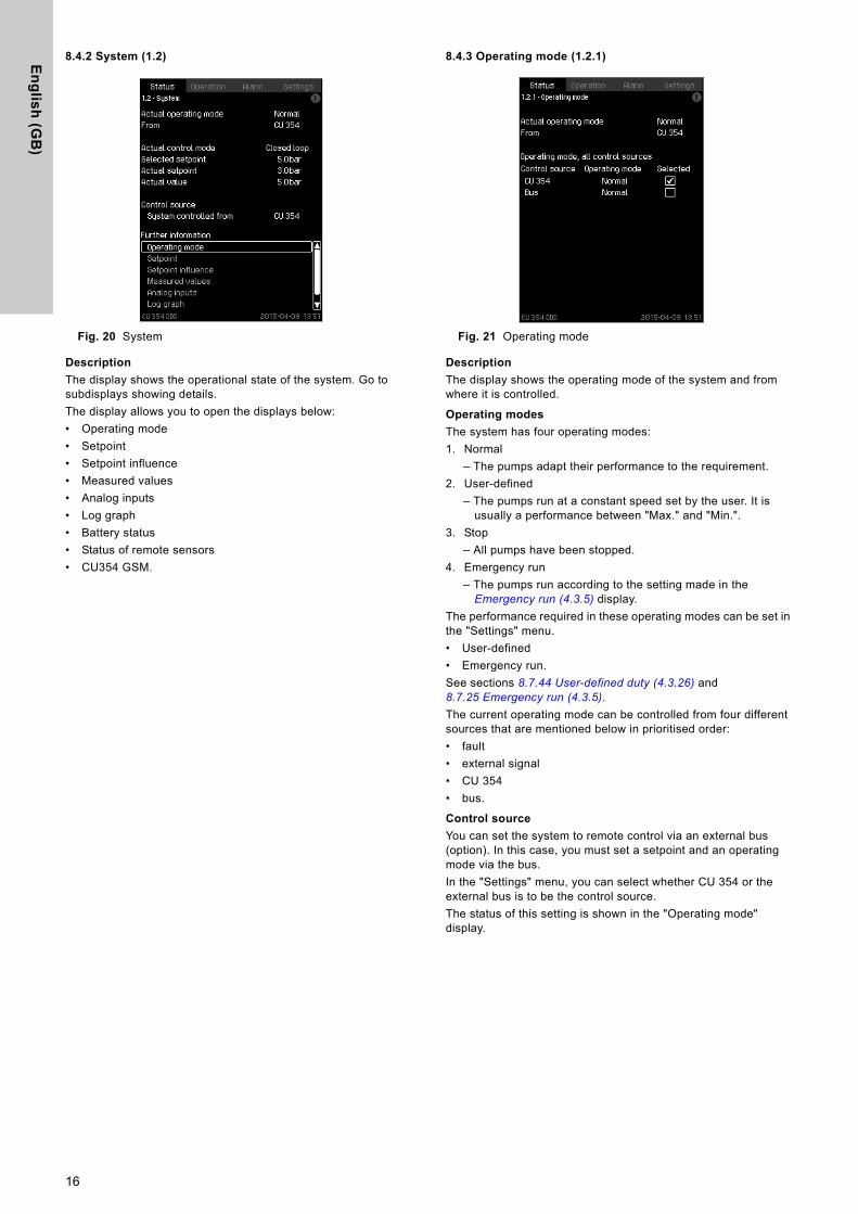
8.4.1 Actual alarms (3.1)
Fig. 19 Actual alarms
Description
The display shows active unreset alarms and warnings.For further information, see also sections 8.6.2 Actual alarms (3.1) and 8.6.3 Alarm log (3.2).
A
B
C
D
E
F
GH
I
If a fault has occurred, a warning or alarm symbol will be shown in line (C) together with the cause and fault code, for instance "Overtemperature (64)".
Pump status indicator Description
Rotating, green Pump running.Permanently green Pump ready (not running).Rotating, yellow Warning. Pump running.Permanently yellow Warning. Pump ready (not running).Permanently red Alarm. Pump stopped.
15
En
glis
h (G
B)
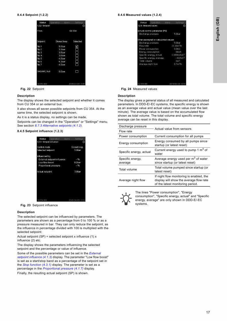
8.4.2 System (1.2)
Fig. 20 System
Description
The display shows the operational state of the system. Go to subdisplays showing details.The display allows you to open the displays below:• Operating mode• Setpoint• Setpoint influence• Measured values• Analog inputs• Log graph• Battery status• Status of remote sensors• CU354 GSM.
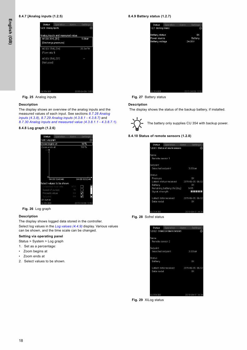
8.4.3 Operating mode (1.2.1)
Fig. 21 Operating mode
Description
The display shows the operating mode of the system and from where it is controlled.
Operating modes
The system has four operating modes:1. Normal
– The pumps adapt their performance to the requirement.2. User-defined
– The pumps run at a constant speed set by the user. It is usually a performance between "Max." and "Min.".
3. Stop– All pumps have been stopped.
4. Emergency run– The pumps run according to the setting made in the
Emergency run (4.3.5) display.The performance required in these operating modes can be set in the "Settings" menu.• User-defined• Emergency run.See sections 8.7.44 User-defined duty (4.3.26) and 8.7.25 Emergency run (4.3.5).The current operating mode can be controlled from four different sources that are mentioned below in prioritised order: • fault• external signal• CU 354• bus.
Control source
You can set the system to remote control via an external bus (option). In this case, you must set a setpoint and an operating mode via the bus. In the "Settings" menu, you can select whether CU 354 or the external bus is to be the control source.The status of this setting is shown in the "Operating mode" display.
16
En
gli
sh
(G
B)
8.4.4 Setpoint (1.2.2)
Fig. 22 Setpoint
Description
The display shows the selected setpoint and whether it comes from CU 354 or an external bus.It also shows all seven possible setpoints from CU 354. At the same time, the selected setpoint is shown.As it is a status display, no settings can be made.Setpoints can be changed in the "Operation" or "Settings" menu. See section 8.7.3 Alternative setpoints (4.1.2).
8.4.5 Setpoint influence (1.2.3)
Fig. 23 Setpoint influence
Description
The selected setpoint can be influenced by parameters. The parameters are shown as a percentage from 0 to 100 % or as a pressure measured in bar. They can only reduce the setpoint, as the influence in percentage divided with 100 is multiplied with the selected setpoint:Actual setpoint (SP) = selected setpoint x influence (1) x influence (2) etc.The display shows the parameters influencing the selected setpoint and the percentage or value of influence.Some of the possible parameters can be set in the External setpoint influence (4.1.3) display. The parameter "Low flow boost" is set as a start/stop band as a percentage of the setpoint set in the Stop function (4.3.1) display. The parameter is set as a percentage in the Proportional pressure (4.1.7) display.Finally, the resulting actual setpoint (SP) is shown.
8.4.6 Measured values (1.2.4)
Fig. 24 Measured values
Description
The display gives a general status of all measured and calculated parameters. In DDD-E/-EC systems, the specific energy is shown as an average value and actual value (mean value over the last minute). The average value is based on the accumulated flow shown as total volume. The total volume and specific energy average can be reset in this display.
Discharge pressureActual value from sensors
Flow ratePower consumption Current consumption for all pumps
Energy consumption Energy consumed by all pumps since startup (or latest reset)
Specific energy, actual Current energy used to pump 1 m3 of water
Specific energy, average
Average energy used per m3 of water since startup (or latest reset)
Total volume Total volume pumped since startup (or latest reset)
Average night flowIf night flow monitoring is enabled, the display will show the average flow rate of the latest monitoring period.
The lines "Power consumption", "Energy consumption", "Specific energy, actual" and "Specific energy, average" are only shown in DDD-E/-EC systems.
17
En
glis
h (G
B)
8.4.7 [Analog inputs (1.2.5)
Fig. 25 Analog inputs
Description
The display shows an overview of the analog inputs and the measured values of each input. See sections 8.7.28 Analog inputs (4.3.8), 8.7.29 Analog inputs (4.3.8.1 - 4.3.8.7) and 8.7.30 Analog inputs and measured value (4.3.8.1.1 - 4.3.8.7.1).
8.4.8 Log graph (1.2.6)
Fig. 26 Log graph
Description
The display shows logged data stored in the controller. Select log values in the Log values (4.4.9) display. Various values can be shown, and the time scale can be changed.
Setting via operating panel
Status > System > Log graph1. Set as a percentage: • Zoom begins at• Zoom ends at2. Select values to be shown.
8.4.9 Battery status (1.2.7)
Fig. 27 Battery status
Description
The display shows the status of the backup battery, if installed.
8.4.10 Status of remote sensors (1.2.8)
Fig. 28 Sofrel status
Fig. 29 XiLog status
The battery only supplies CU 354 with backup power.
18
En
gli
sh
(G
B)
Description
The display shows the different status information on the logger:Name: the name set for the sensor during commission, typically the site name.*Setpoint: the selected minimum pressure for the critical point.*Sofrel Status:• Pressure• Time for last status• Battery• Remaining battery life in days• Signal strength when the status was sent.XiLog Status:• Battery.Latest data received: shows the date and time stamp for the last data package received.*Data Model: status of the current data model.** Common status for both Sofrel and XiLog.
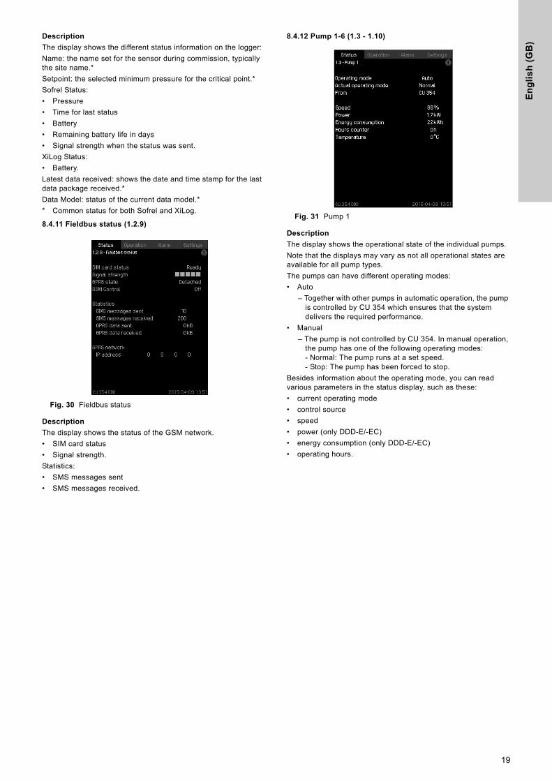
8.4.11 Fieldbus status (1.2.9)
Fig. 30 Fieldbus status
Description
The display shows the status of the GSM network.• SIM card status• Signal strength.Statistics:• SMS messages sent• SMS messages received.
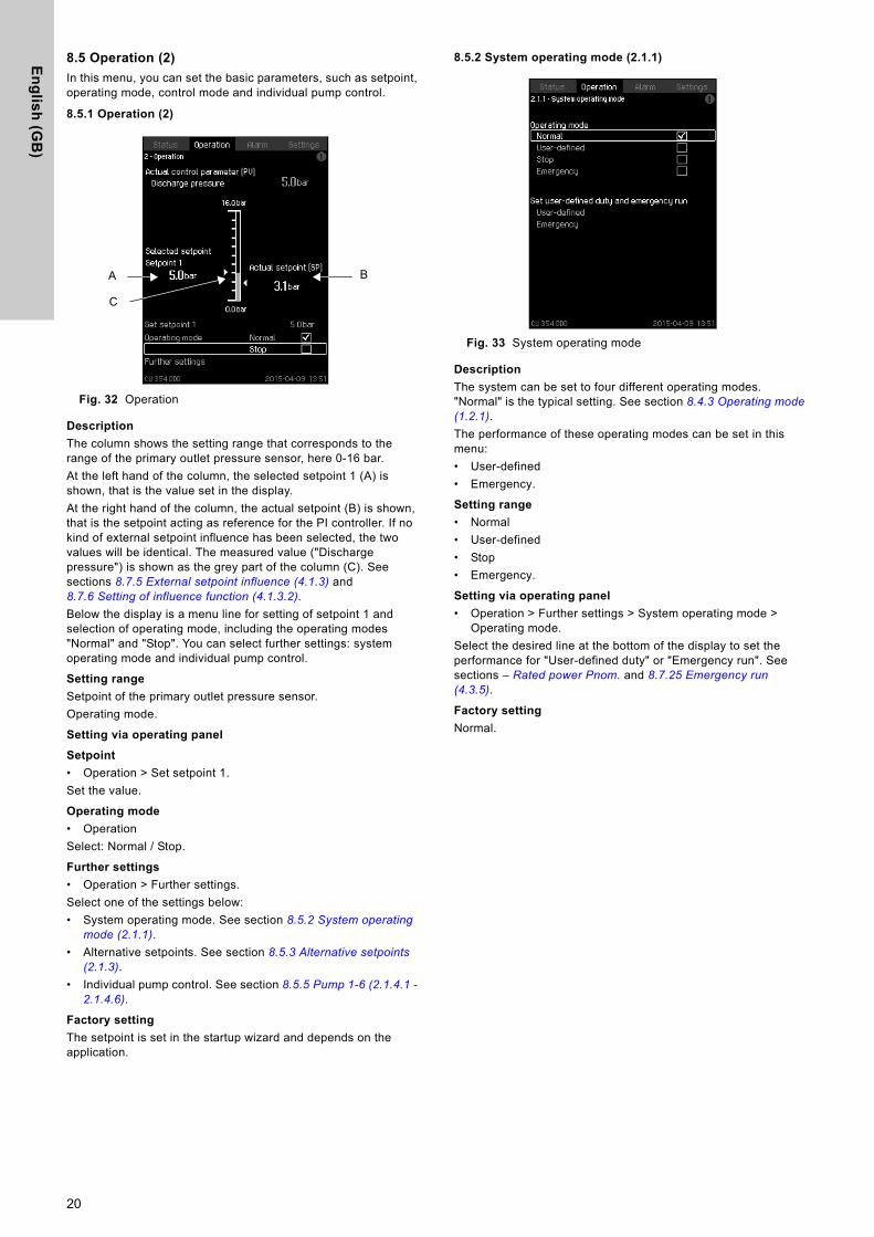
8.4.12 Pump 1-6 (1.3 - 1.10)
Fig. 31 Pump 1
Description
The display shows the operational state of the individual pumps.Note that the displays may vary as not all operational states are available for all pump types.The pumps can have different operating modes:• Auto
– Together with other pumps in automatic operation, the pump is controlled by CU 354 which ensures that the system delivers the required performance.
• Manual– The pump is not controlled by CU 354. In manual operation,
the pump has one of the following operating modes:- Normal: The pump runs at a set speed.- Stop: The pump has been forced to stop.
Besides information about the operating mode, you can read various parameters in the status display, such as these:• current operating mode• control source• speed • power (only DDD-E/-EC)• energy consumption (only DDD-E/-EC)• operating hours.
19
En
glis
h (G
B)
8.5 Operation (2)
In this menu, you can set the basic parameters, such as setpoint, operating mode, control mode and individual pump control.
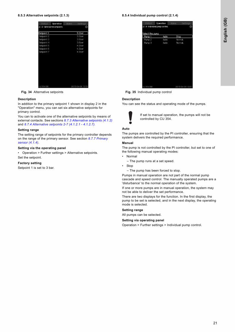
8.5.1 Operation (2)
Fig. 32 Operation
Description
The column shows the setting range that corresponds to the range of the primary outlet pressure sensor, here 0-16 bar.At the left hand of the column, the selected setpoint 1 (A) is shown, that is the value set in the display.At the right hand of the column, the actual setpoint (B) is shown, that is the setpoint acting as reference for the PI controller. If no kind of external setpoint influence has been selected, the two values will be identical. The measured value ("Discharge pressure") is shown as the grey part of the column (C). See sections 8.7.5 External setpoint influence (4.1.3) and 8.7.6 Setting of influence function (4.1.3.2).Below the display is a menu line for setting of setpoint 1 and selection of operating mode, including the operating modes "Normal" and "Stop". You can select further settings: system operating mode and individual pump control.
Setting range
Setpoint of the primary outlet pressure sensor.Operating mode.
Setting via operating panel
Setpoint
• Operation > Set setpoint 1.Set the value.
Operating mode
• OperationSelect: Normal / Stop.
Further settings
• Operation > Further settings.Select one of the settings below:• System operating mode. See section 8.5.2 System operating
mode (2.1.1).• Alternative setpoints. See section 8.5.3 Alternative setpoints
(2.1.3).• Individual pump control. See section 8.5.5 Pump 1-6 (2.1.4.1 -
2.1.4.6).
Factory setting
The setpoint is set in the startup wizard and depends on the application.
8.5.2 System operating mode (2.1.1)
Fig. 33 System operating mode
Description
The system can be set to four different operating modes. "Normal" is the typical setting. See section 8.4.3 Operating mode (1.2.1).The performance of these operating modes can be set in this menu: • User-defined• Emergency.
Setting range
• Normal• User-defined• Stop• Emergency.
Setting via operating panel
• Operation > Further settings > System operating mode > Operating mode.
Select the desired line at the bottom of the display to set the performance for "User-defined duty" or "Emergency run". See sections – Rated power Pnom. and 8.7.25 Emergency run (4.3.5).
Factory setting
Normal.
A
C
B
20
En
gli
sh
(G
B)
8.5.3 Alternative setpoints (2.1.3)
Fig. 34 Alternative setpoints
Description
In addition to the primary setpoint 1 shown in display 2 in the "Operation" menu, you can set six alternative setpoints for primary control. You can to activate one of the alternative setpoints by means of external contacts. See sections 8.7.3 Alternative setpoints (4.1.2) and 8.7.4 Alternative setpoints 2-7 (4.1.2.1 - 4.1.2.7).
Setting range
The setting range of setpoints for the primary controller depends on the range of the primary sensor. See section 8.7.7 Primary sensor (4.1.4).
Setting via the operating panel
• Operation > Further settings > Alternative setpoints.Set the setpoint.
Factory setting
Setpoint 1 is set to 3 bar.
8.5.4 Individual pump control (2.1.4)
Fig. 35 Individual pump control
Description
You can see the status and operating mode of the pumps.
Auto
The pumps are controlled by the PI controller, ensuring that the system delivers the required performance.
Manual
The pump is not controlled by the PI controller, but set to one of the following manual operating modes:• Normal
– The pump runs at a set speed.• Stop
– The pump has been forced to stop.Pumps in manual operation are not part of the normal pump cascade and speed control. The manually operated pumps are a 'disturbance' to the normal operation of the system.If one or more pumps are in manual operation, the system may not be able to deliver the set performance.There are two displays for the function. In the first display, the pump to be set is selected, and in the next display, the operating mode is selected.
Setting range
All pumps can be selected.
Setting via operating panel
Operation > Further settings > Individual pump control.
If set to manual operation, the pumps will not be controlled by CU 354.
21
En
glis
h (G
B)
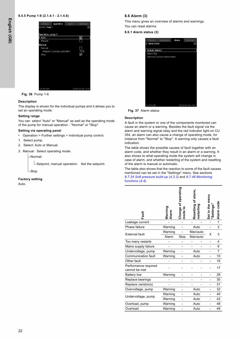
8.5.5 Pump 1-6 (2.1.4.1 - 2.1.4.6)
Fig. 36 Pump 1-6
Description
The display is shown for the individual pumps and it allows you to set an operating mode.
Setting range
You can select "Auto" or "Manual" as well as the operating mode of the pump for manual operation - "Normal" or "Stop".
Setting via operating panel
• Operation > Further settings > Individual pump control.1. Select pump.2. Select: Auto or Manual.
Factory setting
Auto.
8.6 Alarm (3)
This menu gives an overview of alarms and warnings.You can reset alarms.
8.6.1 Alarm status (3)
Fig. 37 Alarm status
Description
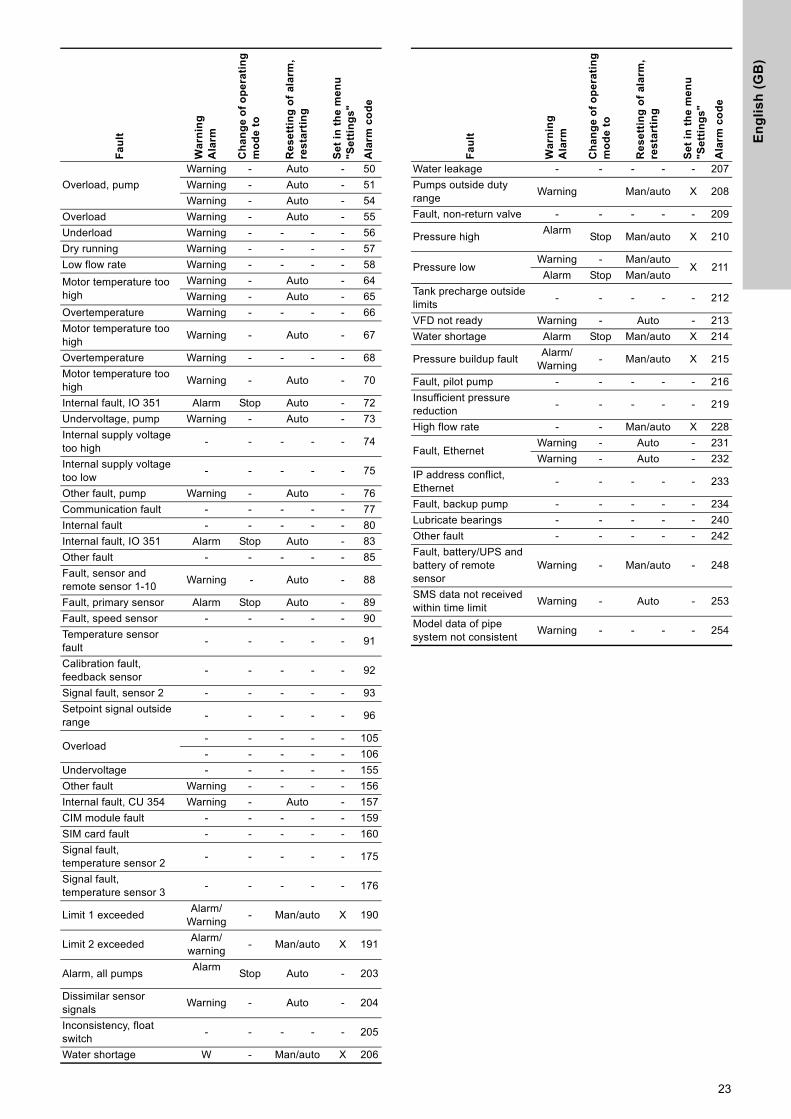
A fault in the system or one of the components monitored can cause an alarm or a warning. Besides the fault signal via the alarm and warning signal relay and the red indicator light on CU 354, an alarm can also cause a change of operating mode, for instance from "Normal" to "Stop". A warning only causes a fault indication.The table shows the possible causes of fault together with an alarm code, and whether they result in an alarm or a warning. It also shows to what operating mode the system will change in case of alarm, and whether restarting of the system and resetting of the alarm is manual or automatic.The table also shows that the reaction to some of the fault causes mentioned can be set in the "Settings" menu. See sections 8.7.24 Soft pressure build-up (4.3.3) and 8.7.48 Monitoring functions (4.4).
3. Manual: Select operating mode.Normal:
Setpoint, manual operation: Set the setpoint.
Stop
Fa
ult
Wa
rnin
gA
larm
Ch
an
ge
of
op
era
tin
g
mo
de
to
Re
se
ttin
g o
f a
larm
, re
sta
rtin
g
Se
t in
th
e m
en
u
"Se
ttin
gs
"
Ala
rm c
od
eLeakage current - - - - - 1Phase failure Warning - Auto - 2
External faultWarning - Man/auto
X 3Alarm Stop Man/auto
Too many restarts - - - - - 4Mains supply failure - - - - - 6Undervoltage, pump Warning - Auto - 7Communication fault Warning - Auto - 10Other fault - - - - - 16Performance required cannot be met - - - - - 17
Battery low Warning - - - - 28Replace bearings - - - - - 30Replace varistor(s) - - - - - 31Overvoltage, pump Warning - Auto - 32
Undervoltage, pumpWarning - Auto - 40Warning - Auto - 42
Overload, pump Warning - Auto - 48Overload Warning - Auto - 49
22
En
gli
sh
(G
B)
Overload, pumpWarning - Auto - 50Warning - Auto - 51Warning - Auto - 54
Overload Warning - Auto - 55Underload Warning - - - - 56Dry running Warning - - - - 57Low flow rate Warning - - - - 58Motor temperature too high
Warning - Auto - 64Warning - Auto - 65
Overtemperature Warning - - - - 66Motor temperature too high Warning - Auto - 67
Overtemperature Warning - - - - 68Motor temperature too high Warning - Auto - 70
Internal fault, IO 351 Alarm Stop Auto - 72Undervoltage, pump Warning - Auto - 73Internal supply voltage too high - - - - - 74
Internal supply voltage too low - - - - - 75
Other fault, pump Warning - Auto - 76Communication fault - - - - - 77Internal fault - - - - - 80Internal fault, IO 351 Alarm Stop Auto - 83Other fault - - - - - 85Fault, sensor and remote sensor 1-10 Warning - Auto - 88
Fault, primary sensor Alarm Stop Auto - 89Fault, speed sensor - - - - - 90Temperature sensor fault - - - - - 91
Calibration fault, feedback sensor - - - - - 92
Signal fault, sensor 2 - - - - - 93Setpoint signal outside range - - - - - 96
Overload- - - - - 105- - - - - 106
Undervoltage - - - - - 155Other fault Warning - - - - 156Internal fault, CU 354 Warning - Auto - 157CIM module fault - - - - - 159SIM card fault - - - - - 160Signal fault, temperature sensor 2 - - - - - 175
Signal fault, temperature sensor 3 - - - - - 176
Limit 1 exceeded Alarm/Warning - Man/auto X 190
Limit 2 exceeded Alarm/warning - Man/auto X 191
Alarm, all pumps Alarm Stop Auto - 203
Dissimilar sensor signals Warning - Auto - 204
Inconsistency, float switch - - - - - 205
Water shortage W - Man/auto X 206
Fa
ult
Wa
rnin
gA
larm
Ch
an
ge
of
op
era
tin
g
mo
de
to
Re
se
ttin
g o
f a
larm
, re
sta
rtin
g
Se
t in
th
e m
en
u
"Se
ttin
gs
"
Ala
rm c
od
e
Water leakage - - - - - 207Pumps outside duty range Warning Man/auto X 208
Fault, non-return valve - - - - - 209
Pressure high Alarm Stop Man/auto X 210
Pressure low Warning - Man/auto
X 211Alarm Stop Man/auto
Tank precharge outside limits - - - - - 212
VFD not ready Warning - Auto - 213Water shortage Alarm Stop Man/auto X 214
Pressure buildup fault Alarm/Warning - Man/auto X 215
Fault, pilot pump - - - - - 216Insufficient pressure reduction - - - - - 219
High flow rate - - Man/auto X 228
Fault, EthernetWarning - Auto - 231Warning - Auto - 232
IP address conflict, Ethernet - - - - - 233
Fault, backup pump - - - - - 234Lubricate bearings - - - - - 240Other fault - - - - - 242Fault, battery/UPS and battery of remote sensor
Warning - Man/auto - 248
SMS data not received within time limit Warning - Auto - 253
Model data of pipe system not consistent Warning - - - - 254
Fa
ult
Wa
rnin
gA
larm
Ch
an
ge
of
op
era
tin
g
mo
de
to
Re
se
ttin
g o
f a
larm
, re
sta
rtin
g
Se
t in
th
e m
en
u
"Se
ttin
gs
"
Ala
rm c
od
e
23
En
glis
h (G
B)
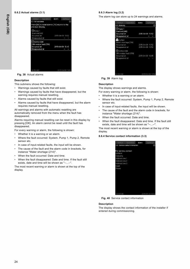
8.6.2 Actual alarms (3.1)
Fig. 38 Actual alarms
Description
This submenu shows the following:• Warnings caused by faults that still exist.• Warnings caused by faults that have disappeared, but the
warning requires manual resetting.• Alarms caused by faults that still exist.• Alarms caused by faults that have disappeared, but the alarm
requires manual resetting.All warnings and alarms with automatic resetting are automatically removed from the menu when the fault has disappeared. Alarms requiring manual resetting can be reset in this display by pressing [OK]. An alarm cannot be reset until the fault has disappeared.For every warning or alarm, the following is shown:• Whether it is a warning or an alarm.• Where the fault occurred: System, Pump 1, Pump 2, Remote
sensor etc.• In case of input-related faults, the input will be shown.• The cause of the fault and the alarm code in brackets, for
instance "Water shortage (214)".• When the fault occurred: Date and time.• When the fault disappeared: Date and time. If the fault still
exists, date and time will be shown as "--...--".The most recent warning or alarm is shown at the top of the display.
8.6.3 Alarm log (3.2)
The alarm log can store up to 24 warnings and alarms.
Fig. 39 Alarm log
Description
The display shows warnings and alarms.For every warning or alarm, the following is shown:• Whether it is a warning or an alarm.• Where the fault occurred: System, Pump 1, Pump 2, Remote
sensor etc.• In case of input-related faults, the input will be shown.• The cause of the fault and the alarm code in brackets, for
instance "Water shortage (214)".• When the fault occurred: Date and time.• When the fault disappeared: Date and time. If the fault still
exists, date and time will be shown as "--...--".The most recent warning or alarm is shown at the top of the display.
8.6.4 Service contact information (3.3)
Fig. 40 Service contact information
Description
The display shows the contact information of the installer if entered during commissioning.
24
En
gli
sh
(G
B)
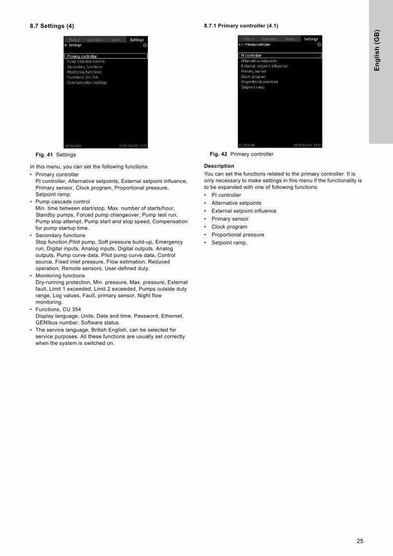
8.7 Settings (4)
Fig. 41 Settings
In this menu, you can set the following functions:• Primary controller
PI controller, Alternative setpoints, External setpoint influence, Primary sensor, Clock program, Proportional pressure, Setpoint ramp.
• Pump cascade controlMin. time between start/stop, Max. number of starts/hour, Standby pumps, Forced pump changeover, Pump test run, Pump stop attempt, Pump start and stop speed, Compensation for pump startup time.
• Secondary functionsStop function,Pilot pump, Soft pressure build-up, Emergency run, Digital inputs, Analog inputs, Digital outputs, Analog outputs, Pump curve data, Pilot pump curve data, Control source, Fixed inlet pressure, Flow estimation, Reduced operation, Remote sensors, User-defined duty.
• Monitoring functionsDry-running protection, Min. pressure, Max. pressure, External fault, Limit 1 exceeded, Limit 2 exceeded, Pumps outside duty range, Log values, Fault, primary sensor, Night flow monitoring.
• Functions, CU 354Display language, Units, Date and time, Password, Ethernet, GENIbus number, Software status.
• The service language, British English, can be selected for service purposes. All these functions are usually set correctly when the system is switched on.
8.7.1 Primary controller (4.1)
Fig. 42 Primary controller
Description
You can set the functions related to the primary controller. It is only necessary to make settings in this menu if the functionality is to be expanded with one of following functions:• PI controller• Alternative setpoints• External setpoint influence• Primary sensor• Clock program• Proportional pressure• Setpoint ramp.
25
En
glis
h (G
B)
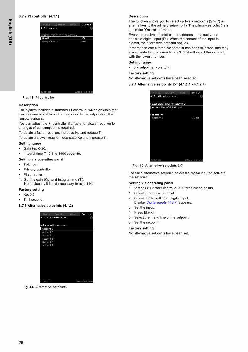
8.7.2 PI controller (4.1.1)
Fig. 43 PI controller
Description
The system includes a standard PI controller which ensures that the pressure is stable and corresponds to the setpoints of the remote sensors. You can adjust the PI controller if a faster or slower reaction to changes of consumption is required.To obtain a faster reaction, increase Kp and reduce Ti.To obtain a slower reaction, decrease Kp and increase Ti.
Setting range
• Gain Kp: 0-30.• Integral time Ti: 0.1 to 3600 seconds.
Setting via operating panel
• Settings• Primary controller• PI controller.1. Set the gain (Kp) and integral time (Ti).
Note: Usually it is not necessary to adjust Kp.
Factory setting
• Kp: 0.5• Ti: 1 second.
8.7.3 Alternative setpoints (4.1.2)
Fig. 44 Alternative setpoints
Description
The function allows you to select up to six setpoints (2 to 7) as alternatives to the primary setpoint (1). The primary setpoint (1) is set in the "Operation" menu.Every alternative setpoint can be addressed manually to a separate digital input (DI). When the contact of the input is closed, the alternative setpoint applies.If more than one alternative setpoint has been selected, and they are activated at the same time, CU 354 will select the setpoint with the lowest number.
Setting range
• Six setpoints, No 2 to 7.
Factory setting
No alternative setpoints have been selected.
8.7.4 Alternative setpoints 2-7 (4.1.2.1 - 4.1.2.7)
Fig. 45 Alternative setpoints 2-7
For each alternative setpoint, select the digital input to activate the setpoint.
Setting via operating panel
• Settings > Primary controller > Alternative setpoints.1. Select alternative setpoint.2. Select: Go to setting of digital input.
Display Digital inputs (4.3.7) appears.3. Set the input.4. Press [Back].5. Select the menu line of the setpoint.6. Set the setpoint.
Factory setting
No alternative setpoints have been set.
26
En
gli
sh
(G
B)
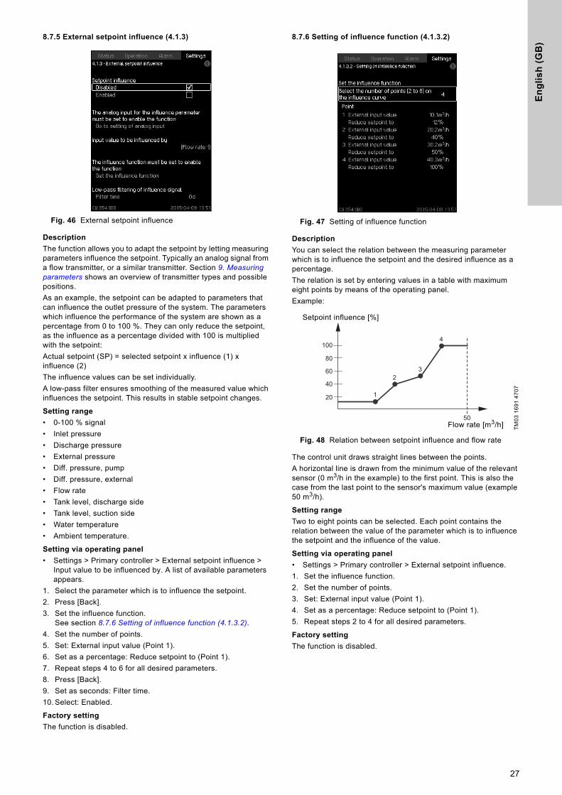
8.7.5 External setpoint influence (4.1.3)
Fig. 46 External setpoint influence
Description
The function allows you to adapt the setpoint by letting measuring parameters influence the setpoint. Typically an analog signal from a flow transmitter, or a similar transmitter. Section 9. Measuring parameters shows an overview of transmitter types and possible positions.As an example, the setpoint can be adapted to parameters that can influence the outlet pressure of the system. The parameters which influence the performance of the system are shown as a percentage from 0 to 100 %. They can only reduce the setpoint, as the influence as a percentage divided with 100 is multiplied with the setpoint:Actual setpoint (SP) = selected setpoint x influence (1) x influence (2)The influence values can be set individually.A low-pass filter ensures smoothing of the measured value which influences the setpoint. This results in stable setpoint changes.
Setting range
• 0-100 % signal• Inlet pressure• Discharge pressure• External pressure• Diff. pressure, pump• Diff. pressure, external• Flow rate• Tank level, discharge side• Tank level, suction side• Water temperature• Ambient temperature.
Setting via operating panel
• Settings > Primary controller > External setpoint influence > Input value to be influenced by. A list of available parameters appears.
1. Select the parameter which is to influence the setpoint.2. Press [Back].3. Set the influence function.
See section 8.7.6 Setting of influence function (4.1.3.2).4. Set the number of points.5. Set: External input value (Point 1).6. Set as a percentage: Reduce setpoint to (Point 1).7. Repeat steps 4 to 6 for all desired parameters.8. Press [Back].9. Set as seconds: Filter time.10. Select: Enabled.
Factory setting
The function is disabled.
8.7.6 Setting of influence function (4.1.3.2)
Fig. 47 Setting of influence function
Description
You can select the relation between the measuring parameter which is to influence the setpoint and the desired influence as a percentage.The relation is set by entering values in a table with maximum eight points by means of the operating panel.Example:
Fig. 48 Relation between setpoint influence and flow rate
The control unit draws straight lines between the points. A horizontal line is drawn from the minimum value of the relevant sensor (0 m3/h in the example) to the first point. This is also the case from the last point to the sensor's maximum value (example 50 m3/h).
Setting range
Two to eight points can be selected. Each point contains the relation between the value of the parameter which is to influence the setpoint and the influence of the value.
Setting via operating panel
• Settings > Primary controller > External setpoint influence.1. Set the influence function.2. Set the number of points.3. Set: External input value (Point 1).4. Set as a percentage: Reduce setpoint to (Point 1).5. Repeat steps 2 to 4 for all desired parameters.
Factory setting
The function is disabled.
TM03
169
1 47
07
20
50
1
23
4
40
60
80
100
Flow rate [m3/h]
Setpoint influence [%]
27
En
glis
h (G
B)
8.7.7 Primary sensor (4.1.4)
Fig. 49 Primary sensor
Description
You can select the control parameter of the system and set the sensor to measure the value.
Setting range
• Discharge pressure• External pressure• Flow rate-3• 0-100 % signal• Not used.
Setting via operating panel
• Settings > Primary controller > Primary sensor > Go to setting of analog input. Display Analog inputs (4.3.8) appears.
1. Select analog input (AI) for the primary sensor and set the parameters.
2. Press [Back].3. Select control parameter for the primary sensor.
Factory setting
The primary parameter is "Discharge pressure". The sensor is connected to AI1 (CU 354). Other primary parameters can be selected in the startup wizard.
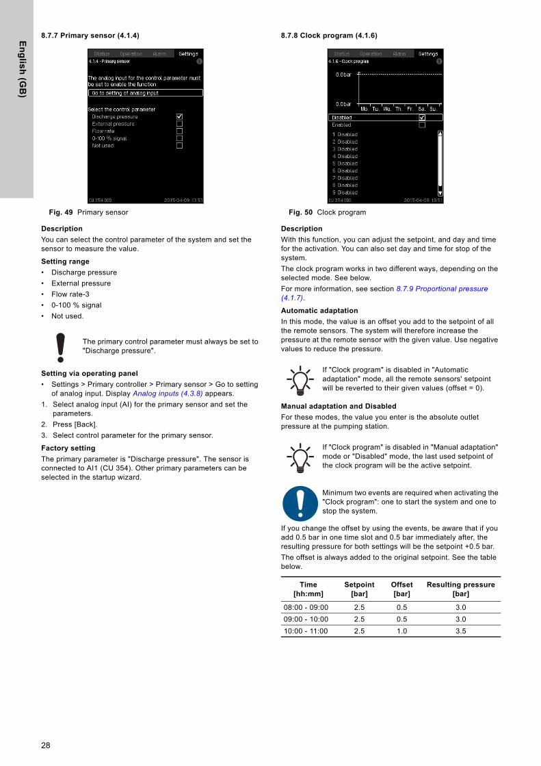
8.7.8 Clock program (4.1.6)
Fig. 50 Clock program
Description
With this function, you can adjust the setpoint, and day and time for the activation. You can also set day and time for stop of the system.The clock program works in two different ways, depending on the selected mode. See below.For more information, see section 8.7.9 Proportional pressure (4.1.7).
Automatic adaptation
In this mode, the value is an offset you add to the setpoint of all the remote sensors. The system will therefore increase the pressure at the remote sensor with the given value. Use negative values to reduce the pressure.
Manual adaptation and Disabled
For these modes, the value you enter is the absolute outlet pressure at the pumping station.
If you change the offset by using the events, be aware that if you add 0.5 bar in one time slot and 0.5 bar immediately after, the resulting pressure for both settings will be the setpoint +0.5 bar. The offset is always added to the original setpoint. See the table below.
The primary control parameter must always be set to "Discharge pressure".
If "Clock program" is disabled in "Automatic adaptation" mode, all the remote sensors' setpoint will be reverted to their given values (offset = 0).
If "Clock program" is disabled in "Manual adaptation" mode or "Disabled" mode, the last used setpoint of the clock program will be the active setpoint.
Minimum two events are required when activating the "Clock program": one to start the system and one to stop the system.
Time[hh:mm]
Setpoint[bar]
Offset[bar]
Resulting pressure[bar]
08:00 - 09:00 2.5 0.5 3.009:00 - 10:00 2.5 0.5 3.010:00 - 11:00 2.5 1.0 3.5
28
En
gli
sh
(G
B)
Setting range
• Activation and setting of event.
Fig. 51 Event 1
Setting via operating panel
• Settings > Primary controller > Clock program.1. Enable the function in display 4.1.6.2. Select and enable one of the ten events in displays 4.1.6.1 to
10.3. Select: Normal or Stop.
(Skip step 4 if you select "Stop".)4. Set the following:• "Setpoint offset,remote sensors" for "Automatic adaptation"
mode• "Setpoint, closed loop" for "Manual adaptation" mode and
"Disabled".5. Set: Time: Hours, Minutes.6. Select the day(s) of week on which the settings are to be
activated.7. Press [Back].8. Repeat steps 2 to 7 if several events are to be enabled. You
can set up to ten events.
Factory setting
The function is disabled.
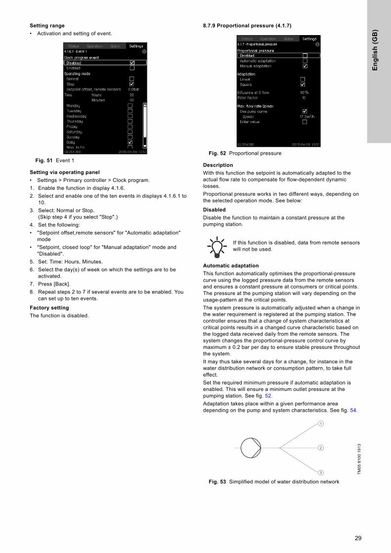
8.7.9 Proportional pressure (4.1.7)
Fig. 52 Proportional pressure
Description
With this function the setpoint is automatically adapted to the actual flow rate to compensate for flow-dependent dynamic losses.Proportional pressure works in two different ways, depending on the selected operation mode. See below:
Disabled
Disable the function to maintain a constant pressure at the pumping station.
Automatic adaptation
This function automatically optimises the proportional-pressure curve using the logged pressure data from the remote sensors and ensures a constant pressure at consumers or critical points. The pressure at the pumping station will vary depending on the usage-pattern at the critical points.The system pressure is automatically adjusted when a change in the water requirement is registered at the pumping station. The controller ensures that a change of system characteristics at critical points results in a changed curve characteristic based on the logged data received daily from the remote sensors. The system changes the proportional-pressure control curve by maximum ± 0.2 bar per day to ensure stable pressure throughout the system.It may thus take several days for a change, for instance in the water distribution network or consumption pattern, to take full effect.Set the required minimum pressure if automatic adaptation is enabled. This will ensure a minimum outlet pressure at the pumping station. See fig. 52.Adaptation takes place within a given performance area depending on the pump and system characteristics. See fig. 54.
Fig. 53 Simplified model of water distribution network
If this function is disabled, data from remote sensors will not be used.
TM05
810
0 19
13
1
2
3
29
En
glis
h (G
B)
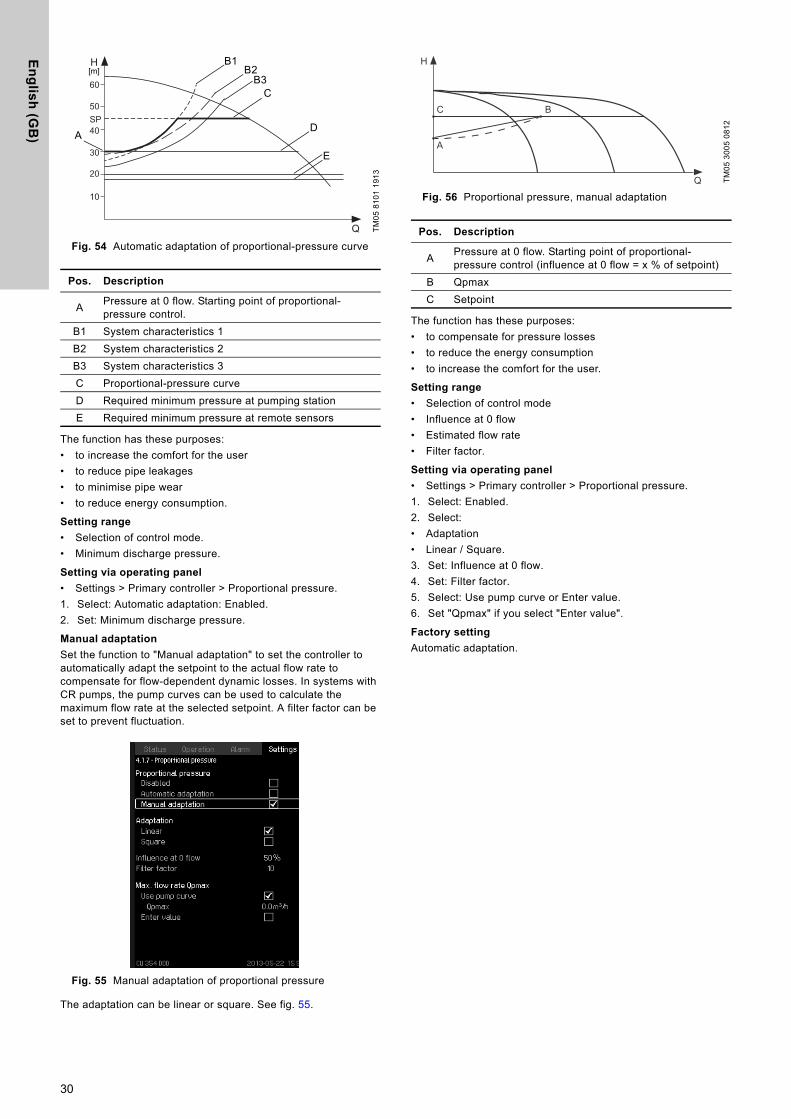
Fig. 54 Automatic adaptation of proportional-pressure curve
The function has these purposes:• to increase the comfort for the user• to reduce pipe leakages• to minimise pipe wear• to reduce energy consumption.
Setting range
• Selection of control mode.• Minimum discharge pressure.
Setting via operating panel
• Settings > Primary controller > Proportional pressure.1. Select: Automatic adaptation: Enabled.2. Set: Minimum discharge pressure.
Manual adaptation
Set the function to "Manual adaptation" to set the controller to automatically adapt the setpoint to the actual flow rate to compensate for flow-dependent dynamic losses. In systems with CR pumps, the pump curves can be used to calculate the maximum flow rate at the selected setpoint. A filter factor can be set to prevent fluctuation.
Fig. 55 Manual adaptation of proportional pressure
The adaptation can be linear or square. See fig. 55.
Fig. 56 Proportional pressure, manual adaptation
The function has these purposes:• to compensate for pressure losses• to reduce the energy consumption• to increase the comfort for the user.
Setting range
• Selection of control mode• Influence at 0 flow• Estimated flow rate• Filter factor.
Setting via operating panel
• Settings > Primary controller > Proportional pressure.1. Select: Enabled.2. Select: • Adaptation• Linear / Square.3. Set: Influence at 0 flow.4. Set: Filter factor.5. Select: Use pump curve or Enter value.6. Set "Qpmax" if you select "Enter value".
Factory setting
Automatic adaptation.
TM05
810
1 19
13
Pos. Description
A Pressure at 0 flow. Starting point of proportional-pressure control.
B1 System characteristics 1B2 System characteristics 2B3 System characteristics 3C Proportional-pressure curveD Required minimum pressure at pumping stationE Required minimum pressure at remote sensors
H
Q
60
50
40
20
10
30
SP
[m]
A
B1
C
D
E
B2B3
TM05
300
5 08
12
Pos. Description
A Pressure at 0 flow. Starting point of proportional-pressure control (influence at 0 flow = x % of setpoint)
B QpmaxC Setpoint
H
C
A
B
Q
30
En
gli
sh
(G
B)
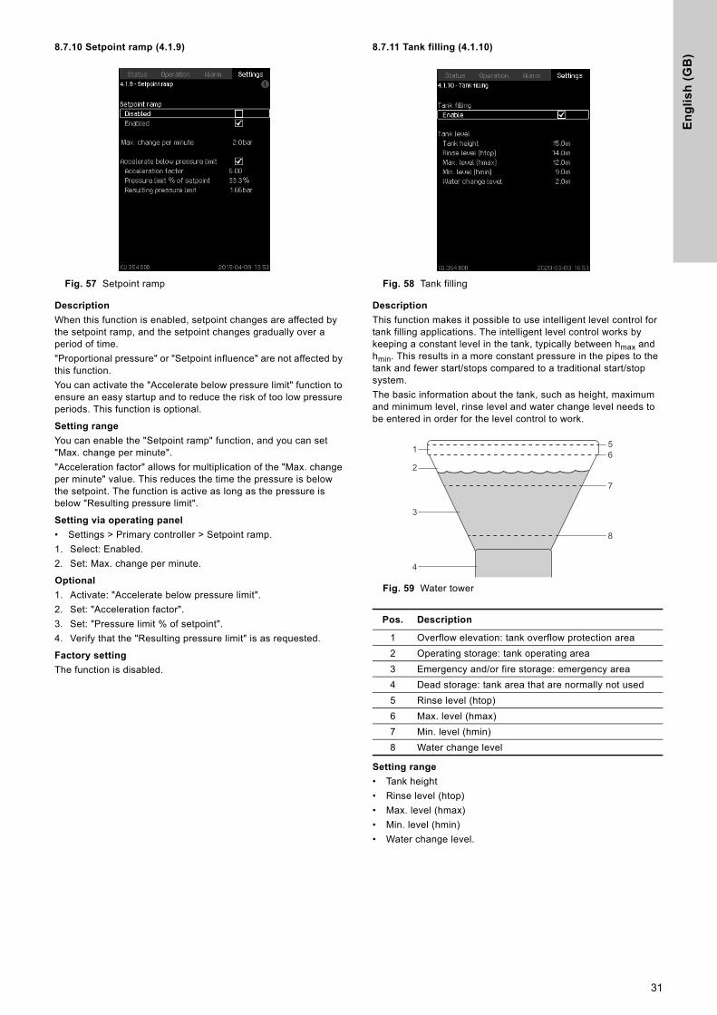
8.7.10 Setpoint ramp (4.1.9)
Fig. 57 Setpoint ramp
Description
When this function is enabled, setpoint changes are affected by the setpoint ramp, and the setpoint changes gradually over a period of time. "Proportional pressure" or "Setpoint influence" are not affected by this function.You can activate the "Accelerate below pressure limit" function to ensure an easy startup and to reduce the risk of too low pressure periods. This function is optional.
Setting range
You can enable the "Setpoint ramp" function, and you can set "Max. change per minute"."Acceleration factor" allows for multiplication of the "Max. change per minute" value. This reduces the time the pressure is below the setpoint. The function is active as long as the pressure is below "Resulting pressure limit".
Setting via operating panel
• Settings > Primary controller > Setpoint ramp.1. Select: Enabled.2. Set: Max. change per minute.
Optional
1. Activate: "Accelerate below pressure limit".2. Set: "Acceleration factor".3. Set: "Pressure limit % of setpoint".4. Verify that the "Resulting pressure limit" is as requested.
Factory setting
The function is disabled.
8.7.11 Tank filling (4.1.10)
Fig. 58 Tank filling
Description
This function makes it possible to use intelligent level control for tank filling applications. The intelligent level control works by keeping a constant level in the tank, typically between hmax and hmin. This results in a more constant pressure in the pipes to the tank and fewer start/stops compared to a traditional start/stop system.The basic information about the tank, such as height, maximum and minimum level, rinse level and water change level needs to be entered in order for the level control to work.
Fig. 59 Water tower
Setting range
• Tank height• Rinse level (htop)• Max. level (hmax)• Min. level (hmin)• Water change level.
Pos. Description
1 Overflow elevation: tank overflow protection area2 Operating storage: tank operating area3 Emergency and/or fire storage: emergency area4 Dead storage: tank area that are normally not used5 Rinse level (htop)6 Max. level (hmax)7 Min. level (hmin)8 Water change level
56
7
8
1
2
3
4
31
En
glis
h (G
B)
Setting via the operating panel
• Settings > Primary controller > Tank filling.1. Select: Enable.2. Set Tank height, which corresponds to the height of the tank.3. Set Rinse level (htop), which is the overflow area of the tank
and is used during forced water change if enabled.4. Set Max. level (hmax), which is the maximum water level of
the tank.5. Set Min. level (hmin), which is the minimum water level of the
tank.6. Set Water change level, which is the minimum water level
used during water change.
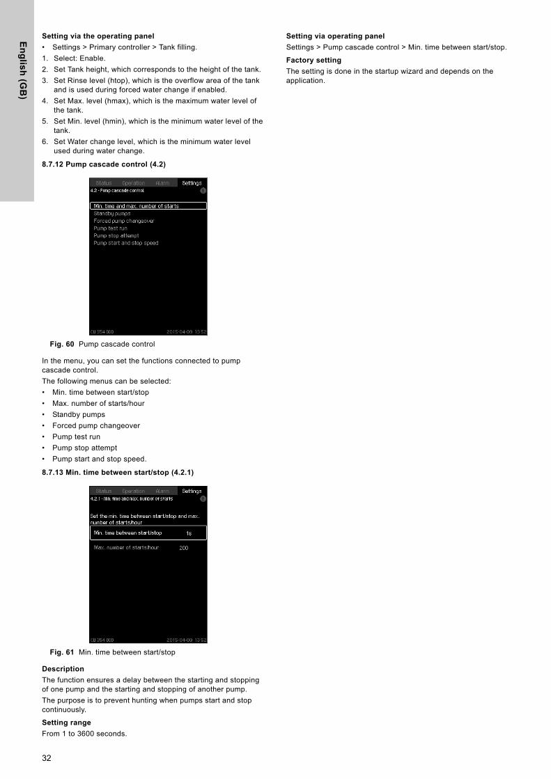
8.7.12 Pump cascade control (4.2)
Fig. 60 Pump cascade control
In the menu, you can set the functions connected to pump cascade control.The following menus can be selected:• Min. time between start/stop• Max. number of starts/hour• Standby pumps• Forced pump changeover• Pump test run• Pump stop attempt• Pump start and stop speed.
8.7.13 Min. time between start/stop (4.2.1)
Fig. 61 Min. time between start/stop
Description
The function ensures a delay between the starting and stopping of one pump and the starting and stopping of another pump.The purpose is to prevent hunting when pumps start and stop continuously.
Setting range
From 1 to 3600 seconds.
Setting via operating panel
Settings > Pump cascade control > Min. time between start/stop.
Factory setting
The setting is done in the startup wizard and depends on the application.
32
En
gli
sh
(G
B)
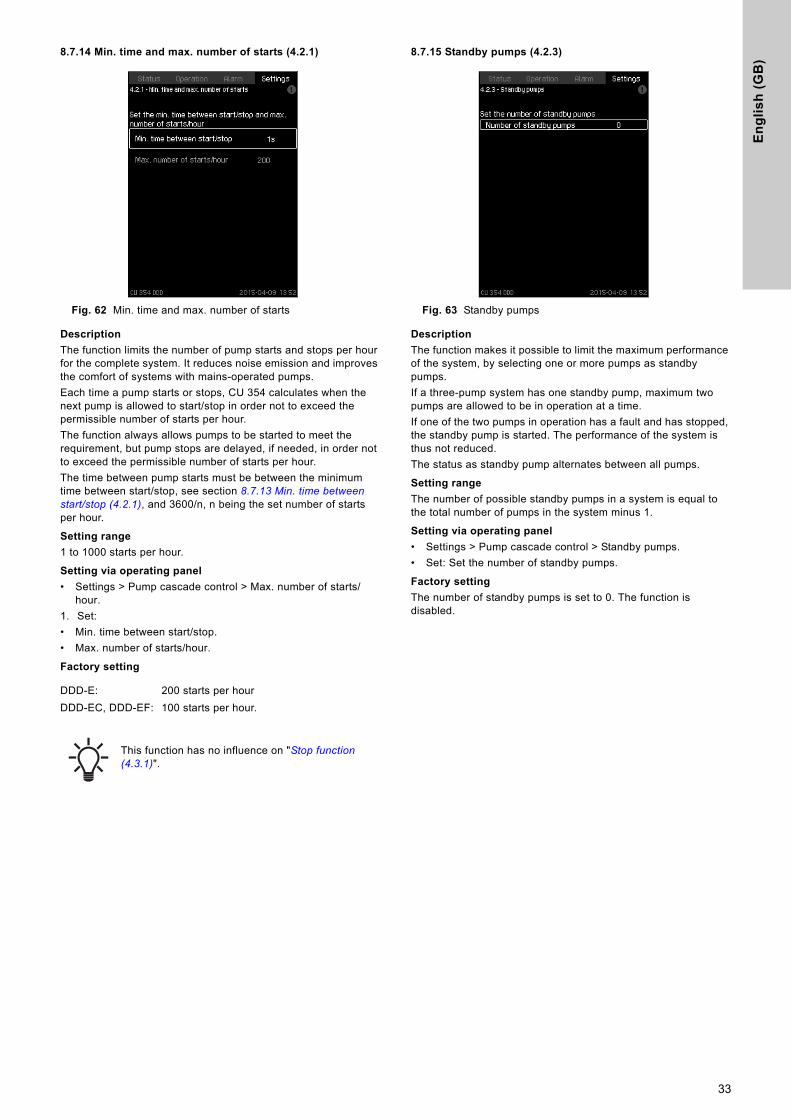
8.7.14 Min. time and max. number of starts (4.2.1)
Fig. 62 Min. time and max. number of starts
Description
The function limits the number of pump starts and stops per hour for the complete system. It reduces noise emission and improves the comfort of systems with mains-operated pumps.Each time a pump starts or stops, CU 354 calculates when the next pump is allowed to start/stop in order not to exceed the permissible number of starts per hour.The function always allows pumps to be started to meet the requirement, but pump stops are delayed, if needed, in order not to exceed the permissible number of starts per hour.The time between pump starts must be between the minimum time between start/stop, see section 8.7.13 Min. time between start/stop (4.2.1), and 3600/n, n being the set number of starts per hour.
Setting range
1 to 1000 starts per hour.
Setting via operating panel
• Settings > Pump cascade control > Max. number of starts/hour.
1. Set: • Min. time between start/stop.• Max. number of starts/hour.
Factory setting
8.7.15 Standby pumps (4.2.3)
Fig. 63 Standby pumps
Description
The function makes it possible to limit the maximum performance of the system, by selecting one or more pumps as standby pumps. If a three-pump system has one standby pump, maximum two pumps are allowed to be in operation at a time.If one of the two pumps in operation has a fault and has stopped, the standby pump is started. The performance of the system is thus not reduced.The status as standby pump alternates between all pumps.
Setting range
The number of possible standby pumps in a system is equal to the total number of pumps in the system minus 1.
Setting via operating panel
• Settings > Pump cascade control > Standby pumps.• Set: Set the number of standby pumps.
Factory setting
The number of standby pumps is set to 0. The function is disabled.
DDD-E: 200 starts per hourDDD-EC, DDD-EF: 100 starts per hour.
This function has no influence on "Stop function (4.3.1)".
33
En
glis
h (G
B)
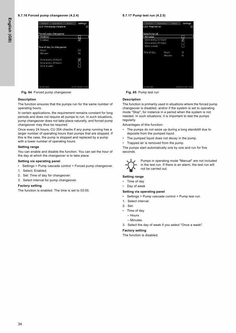
8.7.16 Forced pump changeover (4.2.4)
Fig. 64 Forced pump changeover
Description
The function ensures that the pumps run for the same number of operating hours.In certain applications, the requirement remains constant for long periods and does not require all pumps to run. In such situations, pump changeover does not take place naturally, and forced pump changeover may thus be required.Once every 24 hours, CU 354 checks if any pump running has a larger number of operating hours than pumps that are stopped. If this is the case, the pump is stopped and replaced by a pump with a lower number of operating hours.
Setting range
You can enable and disable the function. You can set the hour of the day at which the changeover is to take place.
Setting via operating panel
• Settings > Pump cascade control > Forced pump changeover.1. Select: Enabled.2. Set: Time of day for changeover.3. Select interval for pump changeover.
Factory setting
The function is enabled. The time is set to 03:00.
8.7.17 Pump test run (4.2.5)
Fig. 65 Pump test run
Description
The function is primarily used in situations where the forced pump changeover is disabled, and/or if the system is set to operating mode "Stop", for instance in a period when the system is not needed. In such situations, it is important to test the pumps regularly.Advantages of this function:• The pumps do not seize up during a long standstill due to
deposits from the pumped liquid.• The pumped liquid does not decay in the pump.• Trapped air is removed from the pump.The pumps start automatically one by one and run for five seconds.
Setting range
• Time of day• Day of week
Setting via operating panel
• Settings > Pump cascade control > Pump test run.1. Select interval.2. Set:• Time of day
– Hours– Minutes.
3. Select the day of week if you select "Once a week".
Factory setting
The function is disabled.
Pumps in operating mode "Manual" are not included in the test run. If there is an alarm, the test run will not be carried out.
34
En
gli
sh
(G
B)
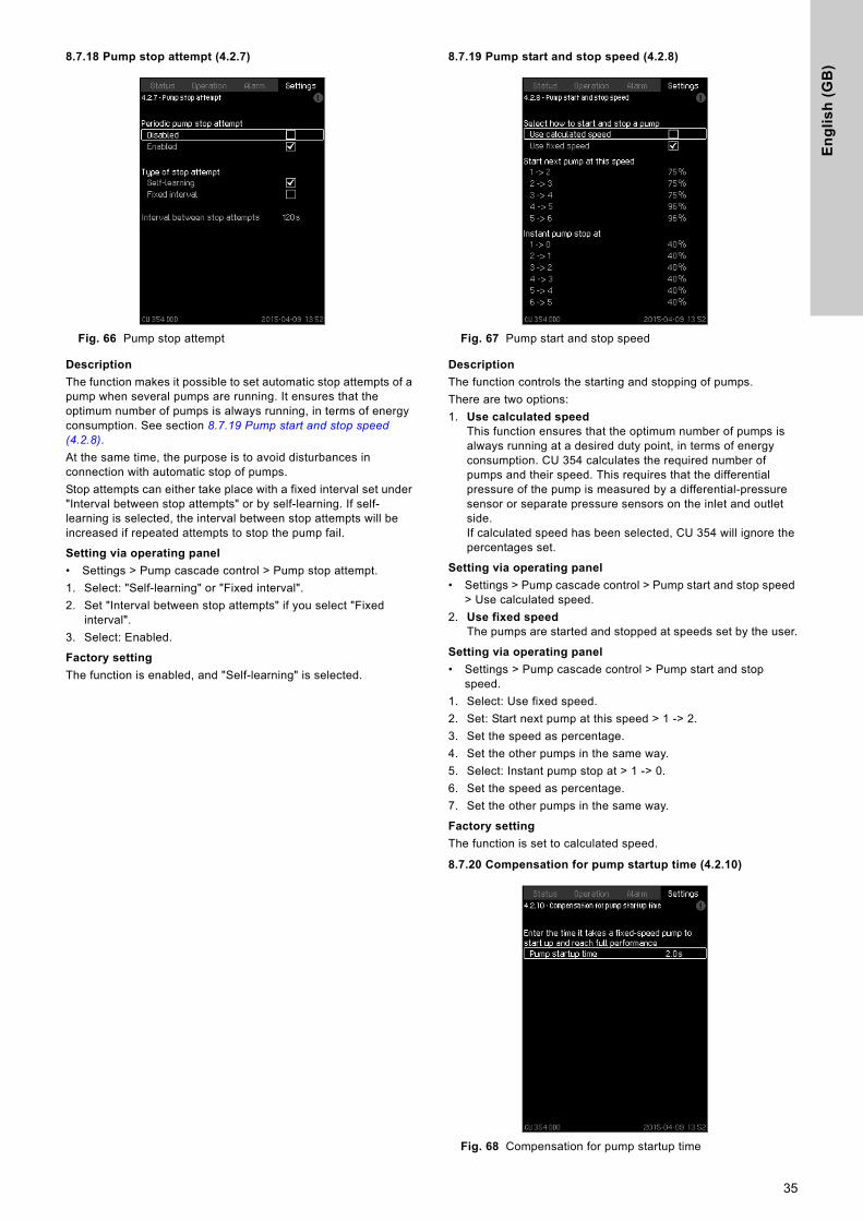
8.7.18 Pump stop attempt (4.2.7)
Fig. 66 Pump stop attempt
Description
The function makes it possible to set automatic stop attempts of a pump when several pumps are running. It ensures that the optimum number of pumps is always running, in terms of energy consumption. See section 8.7.19 Pump start and stop speed (4.2.8). At the same time, the purpose is to avoid disturbances in connection with automatic stop of pumps.Stop attempts can either take place with a fixed interval set under "Interval between stop attempts" or by self-learning. If self-learning is selected, the interval between stop attempts will be increased if repeated attempts to stop the pump fail.
Setting via operating panel
• Settings > Pump cascade control > Pump stop attempt.1. Select: "Self-learning" or "Fixed interval".2. Set "Interval between stop attempts" if you select "Fixed
interval".3. Select: Enabled.
Factory setting
The function is enabled, and "Self-learning" is selected.
8.7.19 Pump start and stop speed (4.2.8)
Fig. 67 Pump start and stop speed
Description
The function controls the starting and stopping of pumps. There are two options:1. Use calculated speed
This function ensures that the optimum number of pumps is always running at a desired duty point, in terms of energy consumption. CU 354 calculates the required number of pumps and their speed. This requires that the differential pressure of the pump is measured by a differential-pressure sensor or separate pressure sensors on the inlet and outlet side.If calculated speed has been selected, CU 354 will ignore the percentages set.
Setting via operating panel
• Settings > Pump cascade control > Pump start and stop speed > Use calculated speed.
2. Use fixed speedThe pumps are started and stopped at speeds set by the user.
Setting via operating panel
• Settings > Pump cascade control > Pump start and stop speed.
1. Select: Use fixed speed.2. Set: Start next pump at this speed > 1 -> 2.3. Set the speed as percentage.4. Set the other pumps in the same way.5. Select: Instant pump stop at > 1 -> 0.6. Set the speed as percentage.7. Set the other pumps in the same way.
Factory setting
The function is set to calculated speed.
8.7.20 Compensation for pump startup time (4.2.10)
Fig. 68 Compensation for pump startup time
35
En
glis
h (G
B)
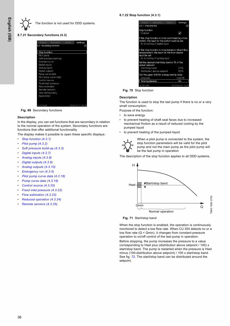
8.7.21 Secondary functions (4.3)
Fig. 69 Secondary functions
Description
In the display, you can set functions that are secondary in relation to the normal operation of the system. Secondary functions are functions that offer additional functionality.The display makes it possible to open these specific displays:• Stop function (4.3.1)
• Pilot pump (4.3.2)
• Soft pressure build-up (4.3.3)
• Digital inputs (4.3.7)
• Analog inputs (4.3.8)
• Digital outputs (4.3.9)
• Analog outputs (4.3.10)
• Emergency run (4.3.5)
• Pilot pump curve data (4.3.18)
• Pump curve data (4.3.19)
• Control source (4.3.20)
• Fixed inlet pressure (4.3.22)
• Flow estimation (4.3.23)
• Reduced operation (4.3.24)
• Remote sensors (4.3.25).
8.7.22 Stop function (4.3.1)
Fig. 70 Stop function
Description
The function is used to stop the last pump if there is no or a very small consumption.Purpose of the function:• to save energy• to prevent heating of shaft seal faces due to increased
mechanical friction as a result of reduced cooling by the pumped liquid
• to prevent heating of the pumped liquid.
The description of the stop function applies to all DDD systems.
Fig. 71 Start/stop band
When the stop function is enabled, the operation is continuously monitored to detect a low flow rate. When CU 354 detects no or a low flow rate (Q < Qmin), it changes from constant-pressure operation to on/off control of the last pump in operation.Before stopping, the pump increases the pressure to a value corresponding to Hset plus (distribution above setpoint / 100) x start/stop band. The pump is restarted when the pressure is Hset minus (100-distribution above setpoint) / 100 x start/stop band. See fig. 72. The start/stop band can be distributed around the setpoint.
The function is not used for DDD systems.
When a pilot pump is connected to the system, the stop function parameters will be valid for the pilot pump and not the main pump as the pilot pump will be the last pump in operation
TM03
169
2 27
05
H
Q
Hset
Qmin
Start/stop band
Normal operation
36
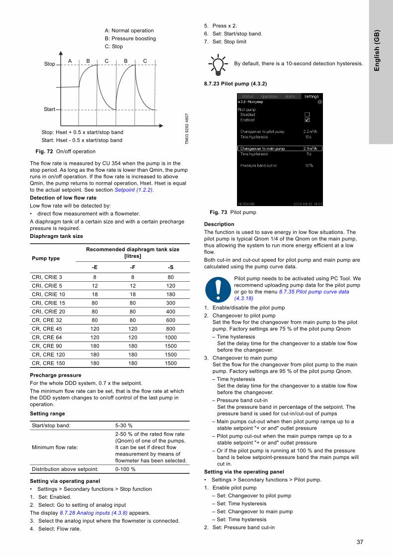
En
gli
sh
(G
B)
Fig. 72 On/off operation
The flow rate is measured by CU 354 when the pump is in the stop period. As long as the flow rate is lower than Qmin, the pump runs in on/off operation. If the flow rate is increased to above Qmin, the pump returns to normal operation, Hset. Hset is equal to the actual setpoint. See section Setpoint (1.2.2).Detection of low flow rate
Low flow rate will be detected by:• direct flow measurement with a flowmeter.A diaphragm tank of a certain size and with a certain precharge pressure is required.Diaphragm tank size
Precharge pressure
For the whole DDD system, 0.7 x the setpoint.The minimum flow rate can be set, that is the flow rate at which the DDD system changes to on/off control of the last pump in operation.
Setting range
Setting via operating panel
• Settings > Secondary functions > Stop function1. Set: Enabled.2. Select: Go to setting of analog inputThe display 8.7.28 Analog inputs (4.3.8) appears.3. Select the analog input where the flowmeter is connected.4. Select: Flow rate.
5. Press x 2.6. Set: Start/stop band.7. Set: Stop limit
8.7.23 Pilot pump (4.3.2)
Fig. 73 Pilot pump
Description
The function is used to save energy in low flow situations. The pilot pump is typical Qnom 1/4 of the Qnom on the main pump, thus allowing the system to run more energy efficient at a low flow. Both cut-in and cut-out speed for pilot pump and main pump are calculated using the pump curve data.
1. Enable/disable the pilot pump2. Changeover to pilot pump
Set the flow for the changeover from main pump to the pilot pump. Factory settings are 75 % of the pilot pump Qnom– Time hysteresis
Set the delay time for the changeover to a stable low flow before the changeover.
3. Changeover to main pumpSet the flow for the changeover from pilot pump to the main pump. Factory settings are 95 % of the pilot pump Qnom.– Time hysteresis
Set the delay time for the changeover to a stable low flow before the changeover.
– Pressure band cut-inSet the pressure band in percentage of the setpoint. The pressure band is used for cut-in/cut-out of pumps
– Main pumps cut-out when then pilot pump ramps up to a stable setpoint "+ or and" outlet pressure
– Pilot pump cut-out when the main pumps ramps up to a stable setpoint "+ or and" outlet pressure
– Or if the pilot pump is running at 100 % and the pressure band is below setpoint-pressure band the main pumps will cut in.
Setting via the operating panel
• Settings > Secondary functions > Pilot pump.1. Enable pilot pump
– Set: Changeover to pilot pump– Set: Time hysteresis– Set: Changeover to main pump– Set: Time hysteresis
2. Set: Pressure band cut-in
TM03
929
2 48
07
Pump type
Recommended diaphragm tank size [litres]
-E -F -S
CRI, CRIE 3 8 8 80CRI, CRIE 5 12 12 120CRI, CRIE 10 18 18 180CRI, CRIE 15 80 80 300CRI, CRIE 20 80 80 400CR, CRE 32 80 80 600CR, CRE 45 120 120 800CR, CRE 64 120 120 1000CR, CRE 90 180 180 1500CR, CRE 120 180 180 1500CR, CRE 150 180 180 1500
Start/stop band: 5-30 %
Minimum flow rate:
2-50 % of the rated flow rate (Qnom) of one of the pumps. It can be set if direct flow measurement by means of flowmeter has been selected.
Distribution above setpoint: 0-100 %
A: Normal operationB: Pressure boostingC: Stop
Stop: Hset + 0.5 x start/stop bandStart: Hset - 0.5 x start/stop band
A B C B CStop
Start
By default, there is a 10-second detection hysteresis.
Pilot pump needs to be activated using PC Tool. We recommend uploading pump data for the pilot pump or go to the menu 8.7.35 Pilot pump curve data (4.3.18)
37
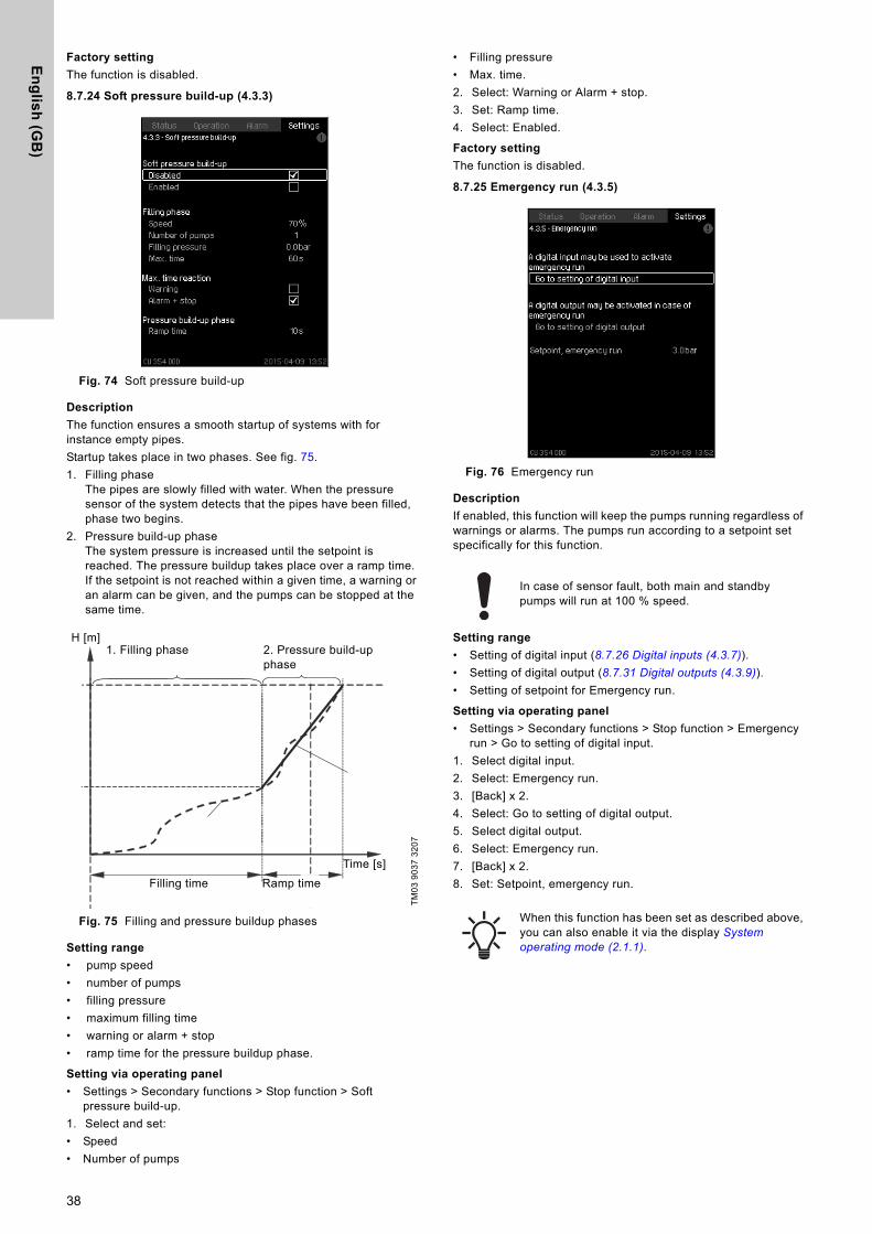
En
glis
h (G
B)
Factory setting
The function is disabled.
8.7.24 Soft pressure build-up (4.3.3)
Fig. 74 Soft pressure build-up
Description
The function ensures a smooth startup of systems with for instance empty pipes.Startup takes place in two phases. See fig. 75.1. Filling phase
The pipes are slowly filled with water. When the pressure sensor of the system detects that the pipes have been filled, phase two begins.
2. Pressure build-up phaseThe system pressure is increased until the setpoint is reached. The pressure buildup takes place over a ramp time. If the setpoint is not reached within a given time, a warning or an alarm can be given, and the pumps can be stopped at the same time.
Fig. 75 Filling and pressure buildup phases
Setting range
• pump speed• number of pumps• filling pressure• maximum filling time• warning or alarm + stop• ramp time for the pressure buildup phase.
Setting via operating panel
• Settings > Secondary functions > Stop function > Soft pressure build-up.
1. Select and set: • Speed• Number of pumps
• Filling pressure• Max. time.2. Select: Warning or Alarm + stop.3. Set: Ramp time.4. Select: Enabled.
Factory setting
The function is disabled.
8.7.25 Emergency run (4.3.5)
Fig. 76 Emergency run
Description
If enabled, this function will keep the pumps running regardless of warnings or alarms. The pumps run according to a setpoint set specifically for this function.
Setting range
• Setting of digital input (8.7.26 Digital inputs (4.3.7)).• Setting of digital output (8.7.31 Digital outputs (4.3.9)).• Setting of setpoint for Emergency run.
Setting via operating panel
• Settings > Secondary functions > Stop function > Emergency run > Go to setting of digital input.
1. Select digital input.2. Select: Emergency run.3. [Back] x 2.4. Select: Go to setting of digital output.5. Select digital output.6. Select: Emergency run.7. [Back] x 2.8. Set: Setpoint, emergency run.
TM03
903
7 32
07
H [m]
Filling time Ramp timeTime [s]
1. Filling phase 2. Pressure build-up phase
In case of sensor fault, both main and standby pumps will run at 100 % speed.
When this function has been set as described above, you can also enable it via the display System operating mode (2.1.1).
38
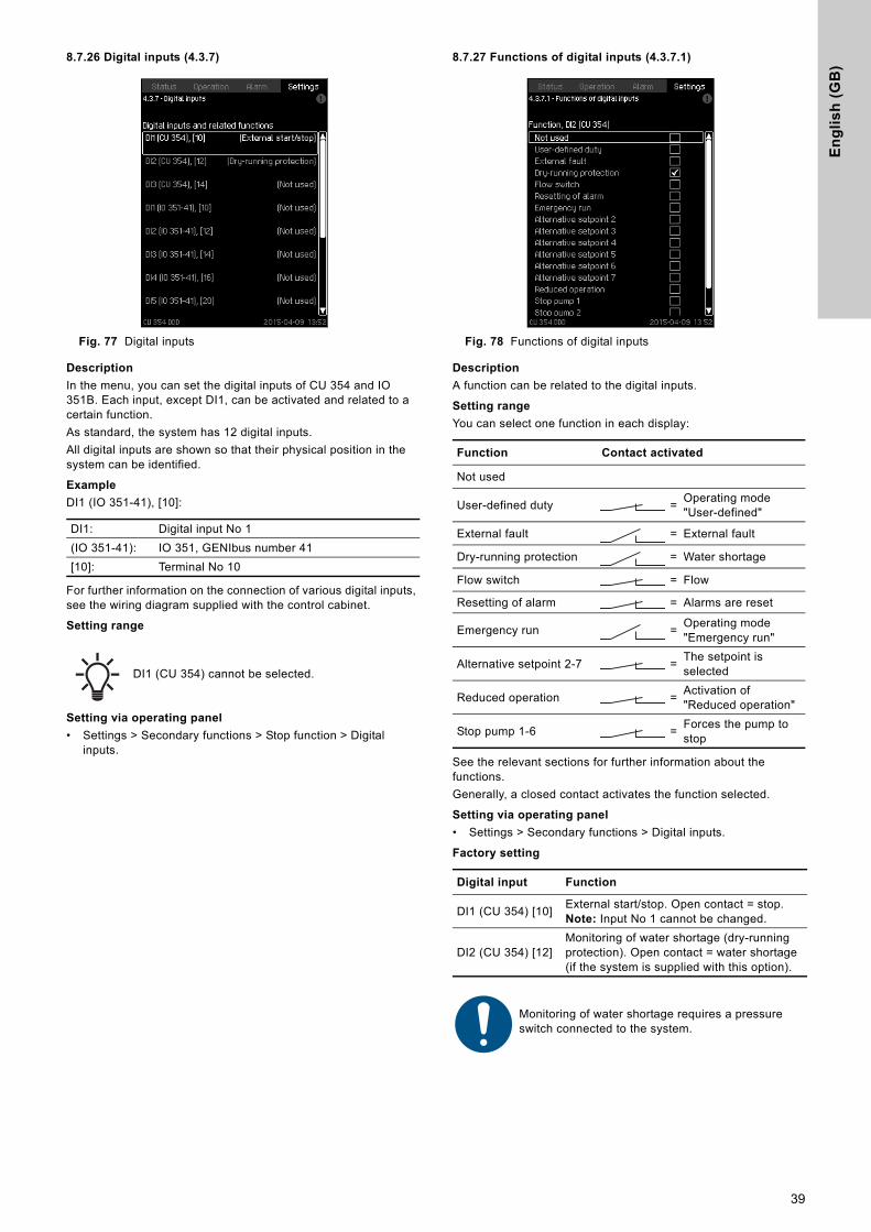
En
gli
sh
(G
B)
8.7.26 Digital inputs (4.3.7)
Fig. 77 Digital inputs
Description
In the menu, you can set the digital inputs of CU 354 and IO 351B. Each input, except DI1, can be activated and related to a certain function.As standard, the system has 12 digital inputs.All digital inputs are shown so that their physical position in the system can be identified.
Example
DI1 (IO 351-41), [10]:
For further information on the connection of various digital inputs, see the wiring diagram supplied with the control cabinet.
Setting range
Setting via operating panel
• Settings > Secondary functions > Stop function > Digital inputs.
8.7.27 Functions of digital inputs (4.3.7.1)
Fig. 78 Functions of digital inputs
Description
A function can be related to the digital inputs.
Setting range
You can select one function in each display:
See the relevant sections for further information about the functions.Generally, a closed contact activates the function selected.
Setting via operating panel
• Settings > Secondary functions > Digital inputs.
Factory setting
DI1: Digital input No 1(IO 351-41): IO 351, GENIbus number 41[10]: Terminal No 10
DI1 (CU 354) cannot be selected.
Function Contact activated
Not used
User-defined duty = Operating mode "User-defined"
External fault = External fault
Dry-running protection = Water shortage
Flow switch = Flow
Resetting of alarm = Alarms are reset
Emergency run = Operating mode "Emergency run"
Alternative setpoint 2-7 = The setpoint is selected
Reduced operation = Activation of "Reduced operation"
Stop pump 1-6 = Forces the pump to stop
Digital input Function
DI1 (CU 354) [10] External start/stop. Open contact = stop.Note: Input No 1 cannot be changed.
DI2 (CU 354) [12]Monitoring of water shortage (dry-running protection). Open contact = water shortage (if the system is supplied with this option).
Monitoring of water shortage requires a pressure switch connected to the system.
39
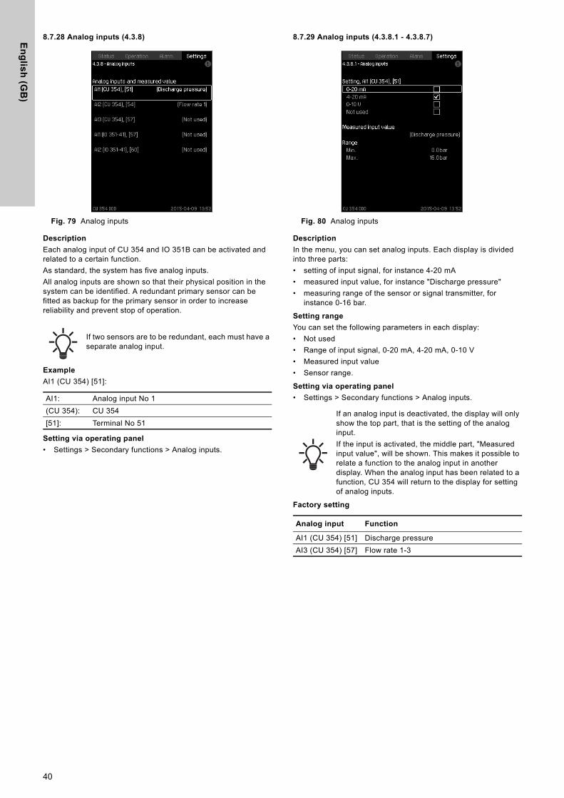
En
glis
h (G
B)
8.7.28 Analog inputs (4.3.8)
Fig. 79 Analog inputs
Description
Each analog input of CU 354 and IO 351B can be activated and related to a certain function.As standard, the system has five analog inputs.All analog inputs are shown so that their physical position in the system can be identified. A redundant primary sensor can be fitted as backup for the primary sensor in order to increase reliability and prevent stop of operation.
Example
AI1 (CU 354) [51]:
Setting via operating panel
• Settings > Secondary functions > Analog inputs.
8.7.29 Analog inputs (4.3.8.1 - 4.3.8.7)
Fig. 80 Analog inputs
Description
In the menu, you can set analog inputs. Each display is divided into three parts:• setting of input signal, for instance 4-20 mA• measured input value, for instance "Discharge pressure"• measuring range of the sensor or signal transmitter, for
instance 0-16 bar.
Setting range
You can set the following parameters in each display: • Not used• Range of input signal, 0-20 mA, 4-20 mA, 0-10 V• Measured input value• Sensor range.
Setting via operating panel
• Settings > Secondary functions > Analog inputs.
Factory setting
If two sensors are to be redundant, each must have a separate analog input.
AI1: Analog input No 1(CU 354): CU 354[51]: Terminal No 51
If an analog input is deactivated, the display will only show the top part, that is the setting of the analog input.If the input is activated, the middle part, "Measured input value", will be shown. This makes it possible to relate a function to the analog input in another display. When the analog input has been related to a function, CU 354 will return to the display for setting of analog inputs.
Analog input Function
AI1 (CU 354) [51] Discharge pressureAI3 (CU 354) [57] Flow rate 1-3
40
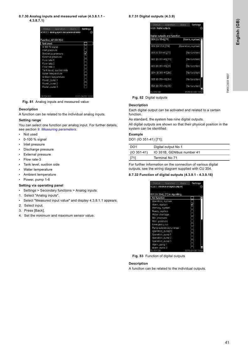
En
gli
sh
(G
B)
8.7.30 Analog inputs and measured value (4.3.8.1.1 - 4.3.8.7.1)
Fig. 81 Analog inputs and measured value
Description
A function can be related to the individual analog inputs.
Setting range
You can select one function per analog input. For further details, see section 9. Measuring parameters.• Not used• 0-100 % signal• Inlet pressure• Discharge pressure• External pressure• Flow rate-3• Tank level, suction side• Water temperature• Ambient temperature• Power, pump 1-6
Setting via operating panel
• Settings > Secondary functions > Analog inputs.1. Select "Analog inputs".• Select "Measured input value" and display 4.3.8.1.1 appears.2. Select input.3. Press [Back].4. Set the minimum and maximum sensor value.
8.7.31 Digital outputs (4.3.9)
Fig. 82 Digital outputs
Description
Each digital output can be activated and related to a certain function.As standard, the system has nine digital outputs. All digital outputs are shown so that their physical position in the system can be identified.
Example
DO1 (IO 351-41) [71]:
For further information on the connection of various digital outputs, see the wiring diagram supplied with CU 354.
8.7.32 Function of digital outputs (4.3.9.1 - 4.3.9.16)
Fig. 83 Function of digital outputs
Description
A function can be related to the individual outputs.
TM03
233
3 46
07
DO1 Digital output No 1(IO 351-41) IO 351B, GENIbus number 41[71] Terminal No 71
41
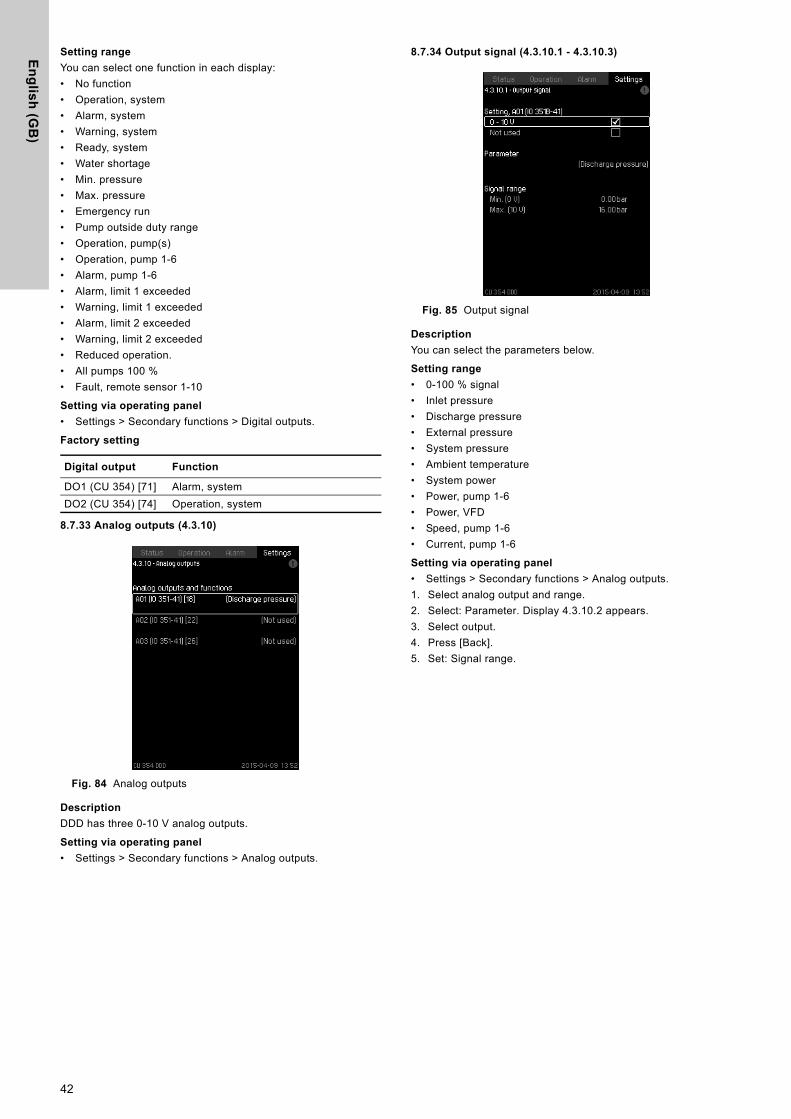
En
glis
h (G
B)
Setting range
You can select one function in each display:• No function• Operation, system• Alarm, system• Warning, system• Ready, system• Water shortage• Min. pressure• Max. pressure• Emergency run• Pump outside duty range• Operation, pump(s)• Operation, pump 1-6• Alarm, pump 1-6• Alarm, limit 1 exceeded• Warning, limit 1 exceeded• Alarm, limit 2 exceeded• Warning, limit 2 exceeded• Reduced operation.• All pumps 100 %• Fault, remote sensor 1-10
Setting via operating panel
• Settings > Secondary functions > Digital outputs.
Factory setting
8.7.33 Analog outputs (4.3.10)
Fig. 84 Analog outputs
Description
DDD has three 0-10 V analog outputs.
Setting via operating panel
• Settings > Secondary functions > Analog outputs.
8.7.34 Output signal (4.3.10.1 - 4.3.10.3)
Fig. 85 Output signal
Description
You can select the parameters below.
Setting range
• 0-100 % signal• Inlet pressure• Discharge pressure• External pressure• System pressure• Ambient temperature• System power• Power, pump 1-6• Power, VFD• Speed, pump 1-6• Current, pump 1-6
Setting via operating panel
• Settings > Secondary functions > Analog outputs.1. Select analog output and range.2. Select: Parameter. Display 4.3.10.2 appears.3. Select output.4. Press [Back].5. Set: Signal range.
Digital output Function
DO1 (CU 354) [71] Alarm, systemDO2 (CU 354) [74] Operation, system
42
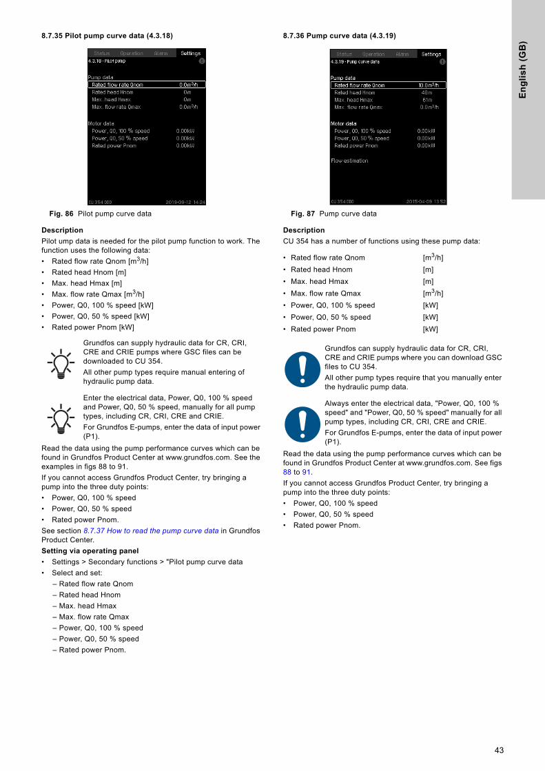
En
gli
sh
(G
B)
8.7.35 Pilot pump curve data (4.3.18)
Fig. 86 Pilot pump curve data
Description
Pilot ump data is needed for the pilot pump function to work. The function uses the following data:• Rated flow rate Qnom [m3/h]• Rated head Hnom [m]• Max. head Hmax [m]• Max. flow rate Qmax [m3/h]• Power, Q0, 100 % speed [kW]• Power, Q0, 50 % speed [kW]• Rated power Pnom [kW]
Read the data using the pump performance curves which can be found in Grundfos Product Center at www.grundfos.com. See the examples in figs 88 to 91.If you cannot access Grundfos Product Center, try bringing a pump into the three duty points:• Power, Q0, 100 % speed• Power, Q0, 50 % speed• Rated power Pnom.See section 8.7.37 How to read the pump curve data in Grundfos Product Center. Setting via operating panel
• Settings > Secondary functions > "Pilot pump curve data• Select and set:
– Rated flow rate Qnom– Rated head Hnom– Max. head Hmax– Max. flow rate Qmax– Power, Q0, 100 % speed– Power, Q0, 50 % speed– Rated power Pnom.
8.7.36 Pump curve data (4.3.19)
Fig. 87 Pump curve data
Description
CU 354 has a number of functions using these pump data:
Read the data using the pump performance curves which can be found in Grundfos Product Center at www.grundfos.com. See figs 88 to 91.If you cannot access Grundfos Product Center, try bringing a pump into the three duty points: • Power, Q0, 100 % speed• Power, Q0, 50 % speed• Rated power Pnom.
Grundfos can supply hydraulic data for CR, CRI, CRE and CRIE pumps where GSC files can be downloaded to CU 354. All other pump types require manual entering of hydraulic pump data.
Enter the electrical data, Power, Q0, 100 % speed and Power, Q0, 50 % speed, manually for all pump types, including CR, CRI, CRE and CRIE.For Grundfos E-pumps, enter the data of input power (P1).
• Rated flow rate Qnom [m3/h]• Rated head Hnom [m]• Max. head Hmax [m]• Max. flow rate Qmax [m3/h]• Power, Q0, 100 % speed [kW]• Power, Q0, 50 % speed [kW]• Rated power Pnom [kW]
Grundfos can supply hydraulic data for CR, CRI, CRE and CRIE pumps where you can download GSC files to CU 354.All other pump types require that you manually enter the hydraulic pump data.
Always enter the electrical data, "Power, Q0, 100 % speed" and "Power, Q0, 50 % speed" manually for all pump types, including CR, CRI, CRE and CRIE.For Grundfos E-pumps, enter the data of input power (P1).
43
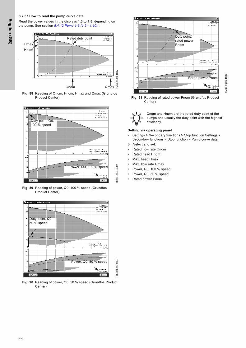
En
glis
h (G
B)
8.7.37 How to read the pump curve data
Read the power values in the displays 1.3 to 1.8, depending on the pump. See section 8.4.12 Pump 1-6 (1.3 - 1.10).
Fig. 88 Reading of Qnom, Hnom, Hmax and Qmax (Grundfos Product Center)
Fig. 89 Reading of power, Q0, 100 % speed (Grundfos Product Center)
Fig. 90 Reading of power, Q0, 50 % speed (Grundfos Product Center)
Fig. 91 Reading of rated power Pnom (Grundfos Product Center)
Setting via operating panel
• Settings > Secondary functions > Stop function Settings > Secondary functions > Stop function > Pump curve data.
6. Select and set:• Rated flow rate Qnom• Rated head Hnom• Max. head Hmax• Max. flow rate Qmax• Power, Q0, 100 % speed• Power, Q0, 50 % speed• Rated power Pnom.
TM03
999
3 48
07TM
03 9
994
4807
TM03
999
5 48
07
Rated duty point
Hnom
Qnom Qmax
Hmax
Power, Q0, 100 % speed
Duty point, Q0, 100 % speed
Power, Q0, 50 % speed
Duty point, Q0, 50 % speed
TM03
999
6 48
07
Qnom and Hnom are the rated duty point of the pumps and usually the duty point with the highest efficiency.
Duty point, rated power Pnom
Rated power Pnom
44
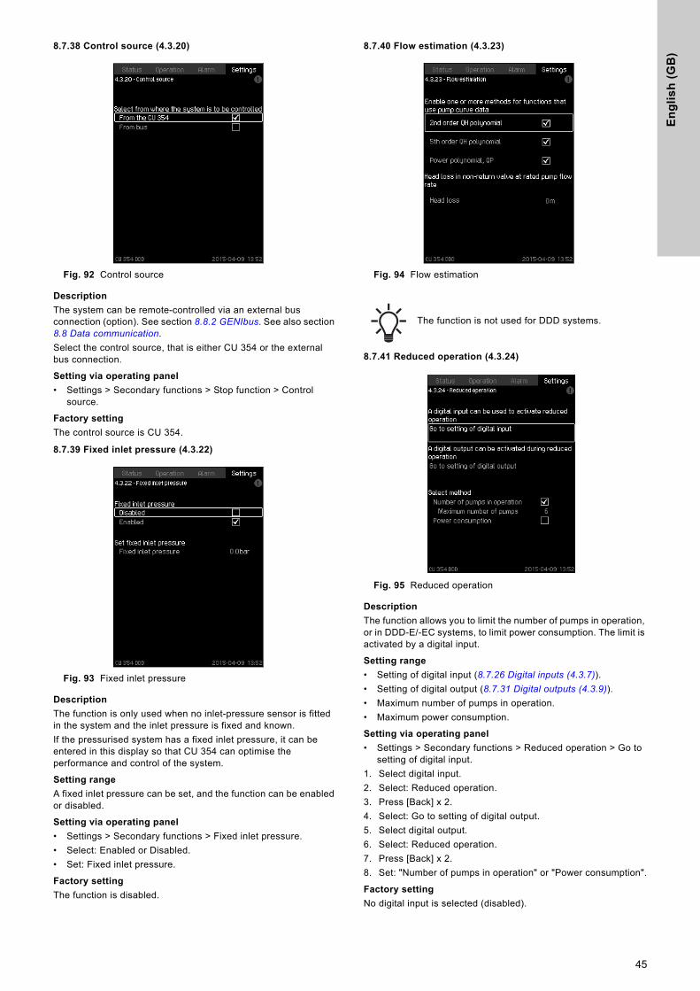
En
gli
sh
(G
B)
8.7.38 Control source (4.3.20)
Fig. 92 Control source
Description
The system can be remote-controlled via an external bus connection (option). See section 8.8.2 GENIbus. See also section 8.8 Data communication.Select the control source, that is either CU 354 or the external bus connection.
Setting via operating panel
• Settings > Secondary functions > Stop function > Control source.
Factory setting
The control source is CU 354.
8.7.39 Fixed inlet pressure (4.3.22)
Fig. 93 Fixed inlet pressure
Description
The function is only used when no inlet-pressure sensor is fitted in the system and the inlet pressure is fixed and known.If the pressurised system has a fixed inlet pressure, it can be entered in this display so that CU 354 can optimise the performance and control of the system.
Setting range
A fixed inlet pressure can be set, and the function can be enabled or disabled.
Setting via operating panel
• Settings > Secondary functions > Fixed inlet pressure.• Select: Enabled or Disabled.• Set: Fixed inlet pressure.
Factory setting
The function is disabled.
8.7.40 Flow estimation (4.3.23)
Fig. 94 Flow estimation
8.7.41 Reduced operation (4.3.24)
Fig. 95 Reduced operation
Description
The function allows you to limit the number of pumps in operation, or in DDD-E/-EC systems, to limit power consumption. The limit is activated by a digital input.
Setting range
• Setting of digital input (8.7.26 Digital inputs (4.3.7)).• Setting of digital output (8.7.31 Digital outputs (4.3.9)).• Maximum number of pumps in operation.• Maximum power consumption.
Setting via operating panel
• Settings > Secondary functions > Reduced operation > Go to setting of digital input.
1. Select digital input.2. Select: Reduced operation.3. Press [Back] x 2.4. Select: Go to setting of digital output.5. Select digital output.6. Select: Reduced operation.7. Press [Back] x 2.8. Set: "Number of pumps in operation" or "Power consumption".
Factory setting
No digital input is selected (disabled).
The function is not used for DDD systems.
45
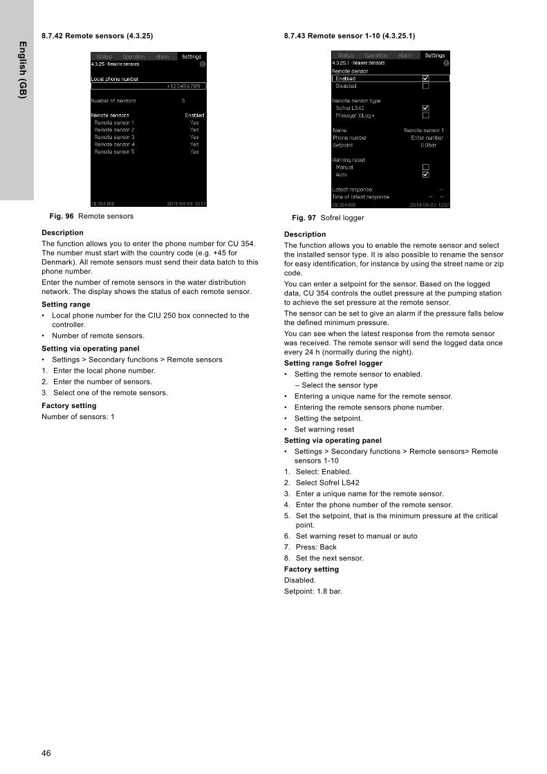
En
glis
h (G
B)
8.7.42 Remote sensors (4.3.25)
Fig. 96 Remote sensors
Description
The function allows you to enter the phone number for CU 354. The number must start with the country code (e.g. +45 for Denmark). All remote sensors must send their data batch to this phone number.Enter the number of remote sensors in the water distribution network. The display shows the status of each remote sensor.
Setting range
• Local phone number for the CIU 250 box connected to the controller.
• Number of remote sensors.
Setting via operating panel
• Settings > Secondary functions > Remote sensors1. Enter the local phone number.2. Enter the number of sensors.3. Select one of the remote sensors.
Factory setting
Number of sensors: 1
8.7.43 Remote sensor 1-10 (4.3.25.1)
Fig. 97 Sofrel logger
Description
The function allows you to enable the remote sensor and select the installed sensor type. It is also possible to rename the sensor for easy identification, for instance by using the street name or zip code.You can enter a setpoint for the sensor. Based on the logged data, CU 354 controls the outlet pressure at the pumping station to achieve the set pressure at the remote sensor.The sensor can be set to give an alarm if the pressure falls below the defined minimum pressure.You can see when the latest response from the remote sensor was received. The remote sensor will send the logged data once every 24 h (normally during the night).Setting range Sofrel logger
• Setting the remote sensor to enabled.– Select the sensor type
• Entering a unique name for the remote sensor.• Entering the remote sensors phone number.• Setting the setpoint.• Set warning resetSetting via operating panel
• Settings > Secondary functions > Remote sensors> Remote sensors 1-10
1. Select: Enabled.2. Select Sofrel LS423. Enter a unique name for the remote sensor.4. Enter the phone number of the remote sensor.5. Set the setpoint, that is the minimum pressure at the critical
point.6. Set warning reset to manual or auto7. Press: Back8. Set the next sensor.Factory setting
Disabled.Setpoint: 1.8 bar.
46
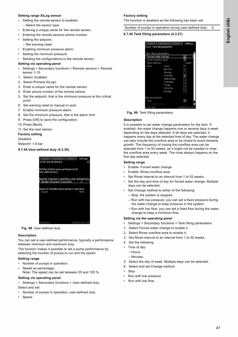
En
gli
sh
(G
B)
Setting range XiLog sensor
• Setting the remote sensor to enabled.– Select the sensor type
• Entering a unique name for the remote sensor.• Entering the remote sensors phone number.• Setting the setpoint.
– Set warning reset• Enabling minimum pressure alarm.• Setting the minimum pressure.• Sending the configurations to the remote sensor.Setting via operating panel
• Settings > Secondary functions > Remote sensors > Remote sensor 1-10
1. Select: Enabled.2. Select Primare XiLog+3. Enter a unique name for the remote sensor.4. Enter phone number of the remote sensor.5. Set the setpoint, that is the minimum pressure at the critical
point.6. Set warning reset to manual or auto7. Enable minimum pressure alarm.8. Set the minimum pressure, that is the alarm limit.9. Press [OK] to send the configuration.10. Press [Back].11. Set the next sensor.Factory setting
Disabled.Setpoint: 1.8 bar.
8.7.44 User-defined duty (4.3.26)
Fig. 98 User-defined duty
Description
You can set a user-defined performance, typically a performance between minimum and maximum duty.The function makes it possible to set a pump performance by selecting the number of pumps to run and the speed.
Setting range
• Number of pumps in operation.• Speed as percentage.
Note: The speed can be set between 25 and 100 %.
Setting via operating panel
• Settings > Secondary functions > User-defined duty.Select and set:• Number of pumps in operation, user-defined duty.• Speed.
Factory setting
The function is disabled as the following has been set:
8.7.45 Tank filling parameters (4.3.27)
Fig. 99 Tank filling parameters
Description
It is possible to set water change parameters for the tank. If enabled, the water change happens one or several days a week, depending on the days selected. If all days are selected, it happens every day at the selected time of day. The water change can also include the overflow area to be rinsed to avoid bacteria growth. The frequency of rinsing the overflow area can be selected from 1 to 52 weeks, as it might not be needed to rinse the overflow area every week. The rinse always happens on the first day selected.
Setting range
• Enable: Forced water change.• Enable: Rinse overflow area.• Set Rinse interval to an interval from 1 to 52 weeks.• Set the day and time of day for forced water change. Multiple
days can be selected.• Set Change method to either of the following:
– Stop: the system is stopped.– Run with low pressure: you can set a fixed pressure during
the water change to keep pressure in the system.– Run with low flow: you can set a fixed flow during the water
change to keep a minimum flow.
Setting via the operating panel
• Settings > Secondary functions > Tank filling parameters.1. Select Forced water change to enable it.2. Select Rinse overflow area to enable it.3. Set Rinse interval to an interval from 1 to 52 weeks.4. Set the following:• Time of day
– Hours– Minutes.
5. Select the day of week. Multiple days can be selected.6. Select and set Change method:• Stop• Run with low pressure• Run with low flow.
Number of pumps in operation during user-defined duty: 0
47
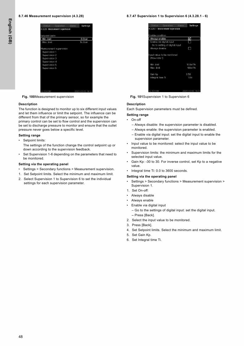
En
glis
h (G
B)
8.7.46 Measurement supervision (4.3.28)
Fig. 100Measurement supervision
Description
The function is designed to monitor up to six different input values and let them influence or limit the setpoint. The influence can be different from that of the primary sensor, so for example the primary control can be set to flow control and the supervision can be set to discharge pressure to monitor and ensure that the outlet pressure never goes below a specific level.
Setting range
• Setpoint limits:The settings of the function change the control setpoint up or down according to the supervision feedback.
• Set Supervision 1-6 depending on the parameters that need to be monitored.
Setting via the operating panel
• Settings > Secondary functions > Measurement supervision.1. Set Setpoint limits. Select the minimum and maximum limit.2. Select Supervision 1 to Supervision 6 to set the individual
settings for each supervision parameter.
8.7.47 Supervision 1 to Supervision 6 (4.3.28.1 - 6)
Fig. 101Supervision 1 to Supervision 6
Description
Each Supervision parameters must be defined.
Setting range
• On-off– Always disable: the supervision parameter is disabled.– Always enable: the supervision parameter is enabled.– Enable via digital input: set the digital input to enable the
supervision parameter.• Input value to be monitored: select the input value to be
monitored.• Supervision limits: the minimum and maximum limits for the
selected input value.• Gain Kp: -30 to 30. For inverse control, set Kp to a negative
value.• Integral time Ti: 0.0 to 3600 seconds.
Setting via the operating panel
• Settings > Secondary functions > Measurement supervision > Supervision 1.
1. Set On-off:• Always disable• Always enable• Enable via digital input
– Go to the settings of digital input: set the digital input.– Press [Back].
2. Select the input value to be monitored.3. Press [Back]. 4. Set Setpoint limits. Select the minimum and maximum limit.5. Set Gain Kp.6. Set Integral time Ti.
48
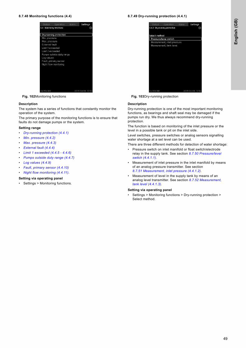
En
gli
sh
(G
B)
8.7.48 Monitoring functions (4.4)
Fig. 102Monitoring functions
Description
The system has a series of functions that constantly monitor the operation of the system.The primary purpose of the monitoring functions is to ensure that faults do not damage pumps or the system.
Setting range
• Dry-running protection (4.4.1)
• Min. pressure (4.4.2)
• Max. pressure (4.4.3)
• External fault (4.4.4)
• Limit 1 exceeded (4.4.5 - 4.4.6)
• Pumps outside duty range (4.4.7)
• Log values (4.4.9)
• Fault, primary sensor (4.4.10)
• Night flow monitoring (4.4.11).
Setting via operating panel
• Settings > Monitoring functions.
8.7.49 Dry-running protection (4.4.1)
Fig. 103Dry-running protection
Description
Dry-running protection is one of the most important monitoring functions, as bearings and shaft seal may be damaged if the pumps run dry. We thus always recommend dry-running protection.The function is based on monitoring of the inlet pressure or the level in a possible tank or pit on the inlet side.Level switches, pressure switches or analog sensors signalling water shortage at a set level can be used.There are three different methods for detection of water shortage:• Pressure switch on inlet manifold or float switch/electrode
relay in the supply tank. See section 8.7.50 Pressure/level switch (4.4.1.1).
• Measurement of inlet pressure in the inlet manifold by means of an analog pressure transmitter. See section 8.7.51 Measurement, inlet pressure (4.4.1.2).
• Measurement of level in the supply tank by means of an analog level transmitter. See section 8.7.52 Measurement, tank level (4.4.1.3).
Setting via operating panel
• Settings > Monitoring functions > Dry-running protection > Select method.
49
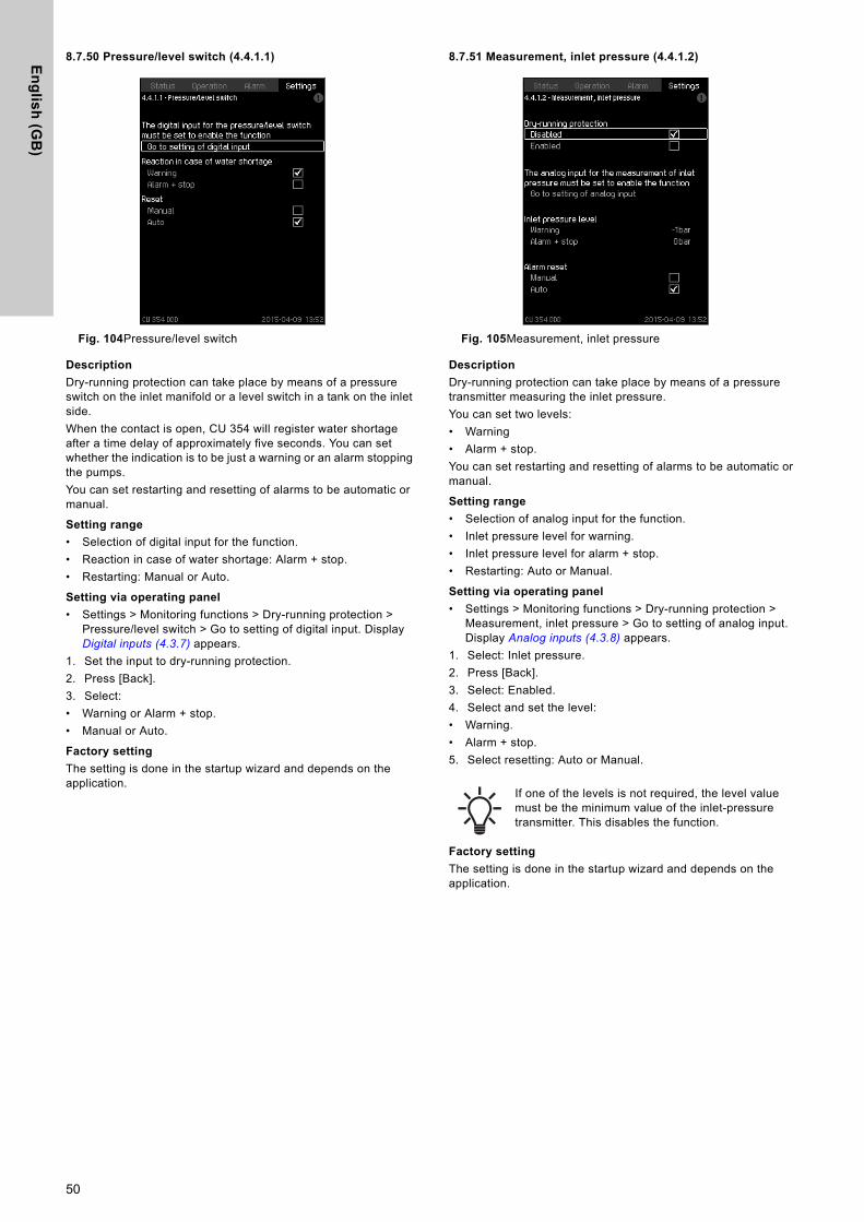
En
glis
h (G
B)
8.7.50 Pressure/level switch (4.4.1.1)
Fig. 104Pressure/level switch
Description
Dry-running protection can take place by means of a pressure switch on the inlet manifold or a level switch in a tank on the inlet side.When the contact is open, CU 354 will register water shortage after a time delay of approximately five seconds. You can set whether the indication is to be just a warning or an alarm stopping the pumps.You can set restarting and resetting of alarms to be automatic or manual.
Setting range
• Selection of digital input for the function.• Reaction in case of water shortage: Alarm + stop.• Restarting: Manual or Auto.
Setting via operating panel
• Settings > Monitoring functions > Dry-running protection > Pressure/level switch > Go to setting of digital input. Display Digital inputs (4.3.7) appears.
1. Set the input to dry-running protection.2. Press [Back].3. Select:• Warning or Alarm + stop.• Manual or Auto.
Factory setting
The setting is done in the startup wizard and depends on the application.
8.7.51 Measurement, inlet pressure (4.4.1.2)
Fig. 105Measurement, inlet pressure
Description
Dry-running protection can take place by means of a pressure transmitter measuring the inlet pressure.You can set two levels:• Warning • Alarm + stop. You can set restarting and resetting of alarms to be automatic or manual.
Setting range
• Selection of analog input for the function.• Inlet pressure level for warning.• Inlet pressure level for alarm + stop.• Restarting: Auto or Manual.
Setting via operating panel
• Settings > Monitoring functions > Dry-running protection > Measurement, inlet pressure > Go to setting of analog input. Display Analog inputs (4.3.8) appears.
1. Select: Inlet pressure.2. Press [Back].3. Select: Enabled.4. Select and set the level: • Warning.• Alarm + stop.5. Select resetting: Auto or Manual.
Factory setting
The setting is done in the startup wizard and depends on the application.
If one of the levels is not required, the level value must be the minimum value of the inlet-pressure transmitter. This disables the function.
50
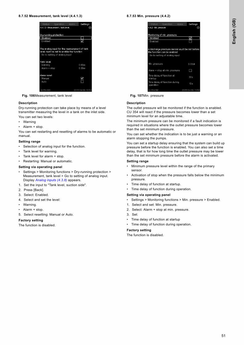
En
gli
sh
(G
B)
8.7.52 Measurement, tank level (4.4.1.3)
Fig. 106Measurement, tank level
Description
Dry-running protection can take place by means of a level transmitter measuring the level in a tank on the inlet side.You can set two levels:• Warning • Alarm + stop.You can set restarting and resetting of alarms to be automatic or manual.
Setting range
• Selection of analog input for the function.• Tank level for warning.• Tank level for alarm + stop.• Restarting: Manual or automatic.
Setting via operating panel
• Settings > Monitoring functions > Dry-running protection > Measurement, tank level > Go to setting of analog input. Display Analog inputs (4.3.8) appears.
1. Set the input to "Tank level, suction side".2. Press [Back].3. Select: Enabled.4. Select and set the level: • Warning.• Alarm + stop.5. Select resetting: Manual or Auto.
Factory setting
The function is disabled.
8.7.53 Min. pressure (4.4.2)
Fig. 107Min. pressure
Description
The outlet pressure will be monitored if the function is enabled. CU 354 will react if the pressure becomes lower than a set minimum level for an adjustable time.The minimum pressure can be monitored if a fault indication is required in situations where the outlet pressure becomes lower than the set minimum pressure.You can set whether the indication is to be just a warning or an alarm stopping the pumps.You can set a startup delay ensuring that the system can build up pressure before the function is enabled. You can also set a time delay, that is for how long time the outlet pressure may be lower than the set minimum pressure before the alarm is activated.
Setting range
• Minimum pressure level within the range of the primary sensor.
• Activation of stop when the pressure falls below the minimum pressure.
• Time delay of function at startup.• Time delay of function during operation.
Setting via operating panel
• Settings > Monitoring functions > Min. pressure > Enabled.1. Select and set: Min. pressure. 2. Select: Alarm + stop at min. pressure.3. Set: • Time delay of function at startup• Time delay of function during operation.
Factory setting
The function is disabled.
51
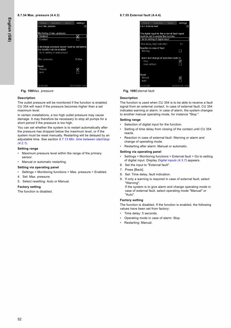
En
glis
h (G
B)
8.7.54 Max. pressure (4.4.3)
Fig. 108Max. pressure
Description
The outlet pressure will be monitored if the function is enabled. CU 354 will react if the pressure becomes higher than a set maximum level.In certain installations, a too high outlet pressure may cause damage. It may therefore be necessary to stop all pumps for a short period if the pressure is too high. You can set whether the system is to restart automatically after the pressure has dropped below the maximum level, or if the system must be reset manually. Restarting will be delayed by an adjustable time. See section 8.7.13 Min. time between start/stop (4.2.1).
Setting range
• Maximum pressure level within the range of the primary sensor.
• Manual or automatic restarting.
Setting via operating panel
• Settings > Monitoring functions > Max. pressure > Enabled.4. Set: Max. pressure. 5. Select resetting: Auto or Manual.
Factory setting
The function is disabled.
8.7.55 External fault (4.4.4)
Fig. 109External fault
Description
The function is used when CU 354 is to be able to receive a fault signal from an external contact. In case of external fault, CU 354 indicates warning or alarm. In case of alarm, the system changes to another manual operating mode, for instance "Stop."
Setting range
• Selection of digital input for the function.• Setting of time delay from closing of the contact until CU 354
reacts.• Reaction in case of external fault: Warning or alarm and
change of operating mode.• Restarting after alarm: Manual or automatic.
Setting via operating panel
• Settings > Monitoring functions > External fault > Go to setting of digital input. Display Digital inputs (4.3.7) appears.
6. Set the input to "External fault".7. Press [Back].8. Set: Time delay, fault indication. 9. If only a warning is required in case of external fault, select
"Warning".If the system is to give alarm and change operating mode in case of external fault, select operating mode "Manual" or "Auto".
Factory setting
The function is disabled. If the function is enabled, the following values have been set from factory:• Time delay: 5 seconds.• Operating mode in case of alarm: Stop.• Restarting: Manual.
52
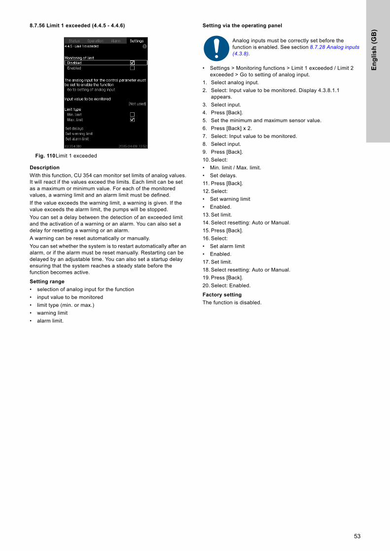
En
gli
sh
(G
B)
8.7.56 Limit 1 exceeded (4.4.5 - 4.4.6)
Fig. 110Limit 1 exceeded
Description
With this function, CU 354 can monitor set limits of analog values. It will react if the values exceed the limits. Each limit can be set as a maximum or minimum value. For each of the monitored values, a warning limit and an alarm limit must be defined. If the value exceeds the warning limit, a warning is given. If the value exceeds the alarm limit, the pumps will be stopped.You can set a delay between the detection of an exceeded limit and the activation of a warning or an alarm. You can also set a delay for resetting a warning or an alarm. A warning can be reset automatically or manually.You can set whether the system is to restart automatically after an alarm, or if the alarm must be reset manually. Restarting can be delayed by an adjustable time. You can also set a startup delay ensuring that the system reaches a steady state before the function becomes active.
Setting range
• selection of analog input for the function• input value to be monitored• limit type (min. or max.)• warning limit• alarm limit.
Setting via the operating panel
• Settings > Monitoring functions > Limit 1 exceeded / Limit 2 exceeded > Go to setting of analog input.
1. Select analog input.2. Select: Input value to be monitored. Display 4.3.8.1.1
appears.3. Select input.4. Press [Back].5. Set the minimum and maximum sensor value.6. Press [Back] x 2.7. Select: Input value to be monitored. 8. Select input.9. Press [Back].10. Select:• Min. limit / Max. limit.• Set delays.11. Press [Back].12. Select:• Set warning limit• Enabled.13. Set limit.14. Select resetting: Auto or Manual.15. Press [Back].16. Select:• Set alarm limit• Enabled.17. Set limit.18. Select resetting: Auto or Manual.19. Press [Back].20. Select: Enabled.
Factory setting
The function is disabled.
Analog inputs must be correctly set before the function is enabled. See section 8.7.28 Analog inputs (4.3.8).
53
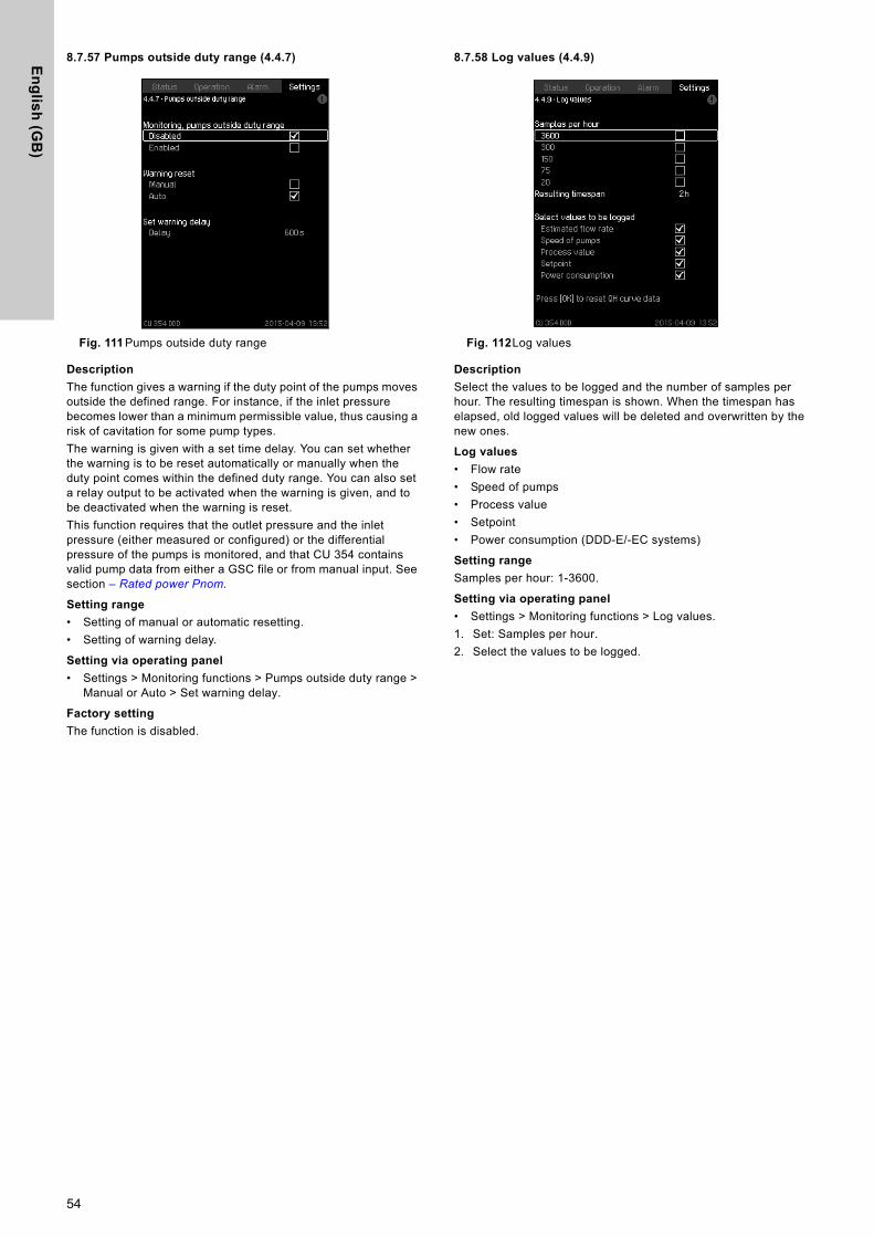
En
glis
h (G
B)
8.7.57 Pumps outside duty range (4.4.7)
Fig. 111 Pumps outside duty range
Description
The function gives a warning if the duty point of the pumps moves outside the defined range. For instance, if the inlet pressure becomes lower than a minimum permissible value, thus causing a risk of cavitation for some pump types.The warning is given with a set time delay. You can set whether the warning is to be reset automatically or manually when the duty point comes within the defined duty range. You can also set a relay output to be activated when the warning is given, and to be deactivated when the warning is reset.This function requires that the outlet pressure and the inlet pressure (either measured or configured) or the differential pressure of the pumps is monitored, and that CU 354 contains valid pump data from either a GSC file or from manual input. See section – Rated power Pnom.
Setting range
• Setting of manual or automatic resetting.• Setting of warning delay.
Setting via operating panel
• Settings > Monitoring functions > Pumps outside duty range > Manual or Auto > Set warning delay.
Factory setting
The function is disabled.
8.7.58 Log values (4.4.9)
Fig. 112Log values
Description
Select the values to be logged and the number of samples per hour. The resulting timespan is shown. When the timespan has elapsed, old logged values will be deleted and overwritten by the new ones.
Log values
• Flow rate• Speed of pumps• Process value• Setpoint• Power consumption (DDD-E/-EC systems)
Setting range
Samples per hour: 1-3600.
Setting via operating panel
• Settings > Monitoring functions > Log values.1. Set: Samples per hour.2. Select the values to be logged.
54
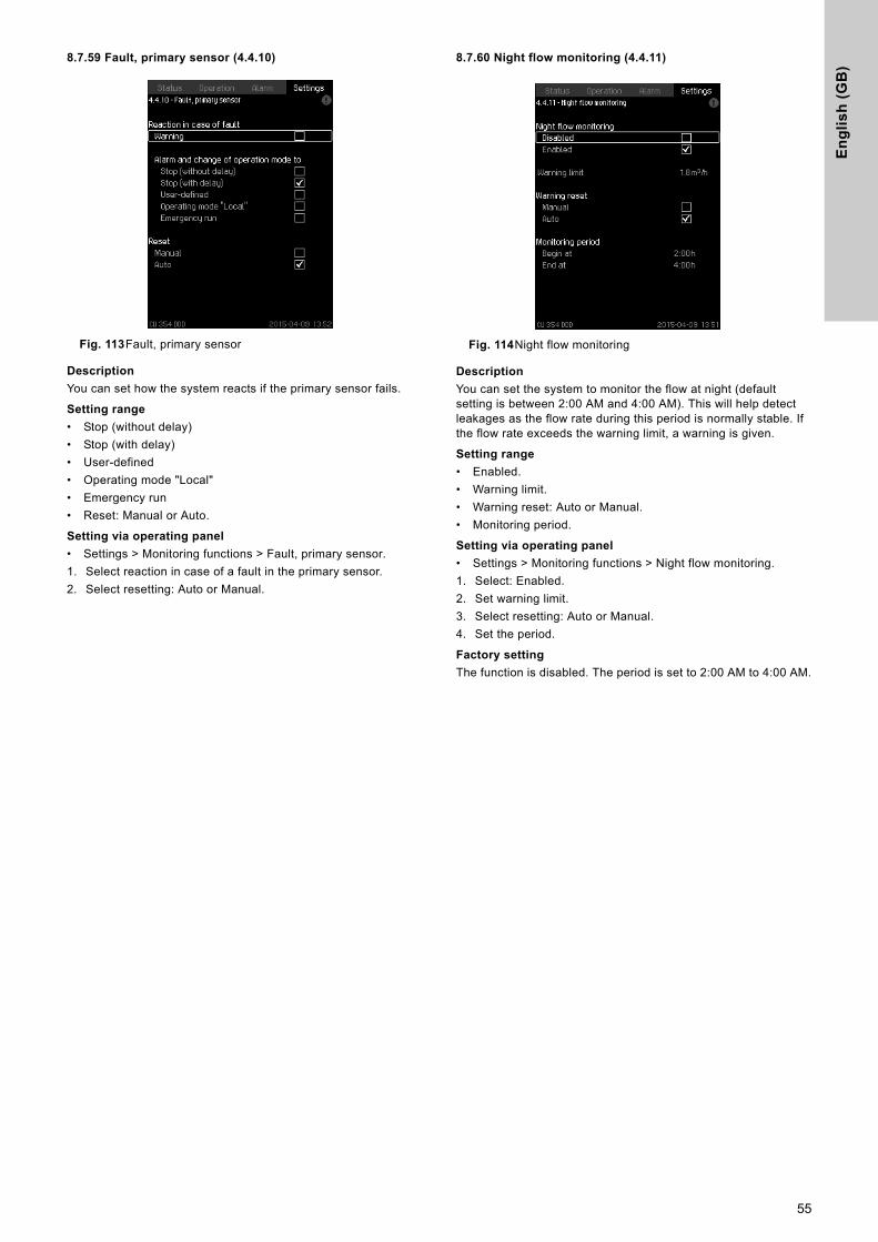
En
gli
sh
(G
B)
8.7.59 Fault, primary sensor (4.4.10)
Fig. 113Fault, primary sensor
Description
You can set how the system reacts if the primary sensor fails.
Setting range
• Stop (without delay)• Stop (with delay)• User-defined• Operating mode "Local"• Emergency run• Reset: Manual or Auto.
Setting via operating panel
• Settings > Monitoring functions > Fault, primary sensor.1. Select reaction in case of a fault in the primary sensor.2. Select resetting: Auto or Manual.
8.7.60 Night flow monitoring (4.4.11)
Fig. 114Night flow monitoring
Description
You can set the system to monitor the flow at night (default setting is between 2:00 AM and 4:00 AM). This will help detect leakages as the flow rate during this period is normally stable. If the flow rate exceeds the warning limit, a warning is given.
Setting range
• Enabled.• Warning limit.• Warning reset: Auto or Manual.• Monitoring period.
Setting via operating panel
• Settings > Monitoring functions > Night flow monitoring.1. Select: Enabled.2. Set warning limit.3. Select resetting: Auto or Manual.4. Set the period.
Factory setting
The function is disabled. The period is set to 2:00 AM to 4:00 AM.
55
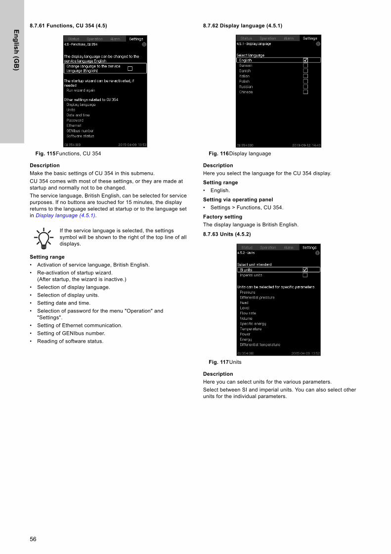
En
glis
h (G
B)
8.7.61 Functions, CU 354 (4.5)
Fig. 115Functions, CU 354
Description
Make the basic settings of CU 354 in this submenu.CU 354 comes with most of these settings, or they are made at startup and normally not to be changed.The service language, British English, can be selected for service purposes. If no buttons are touched for 15 minutes, the display returns to the language selected at startup or to the language set in Display language (4.5.1).
Setting range
• Activation of service language, British English.• Re-activation of startup wizard.
(After startup, the wizard is inactive.)• Selection of display language.• Selection of display units.• Setting date and time.• Selection of password for the menu "Operation" and
"Settings".• Setting of Ethernet communication.• Setting of GENIbus number.• Reading of software status.
8.7.62 Display language (4.5.1)
Fig. 116Display language
Description
Here you select the language for the CU 354 display.
Setting range
• English.
Setting via operating panel
• Settings > Functions, CU 354.
Factory setting
The display language is British English.
8.7.63 Units (4.5.2)
Fig. 117Units
Description
Here you can select units for the various parameters.Select between SI and imperial units. You can also select other units for the individual parameters.
If the service language is selected, the settings symbol will be shown to the right of the top line of all displays.
56
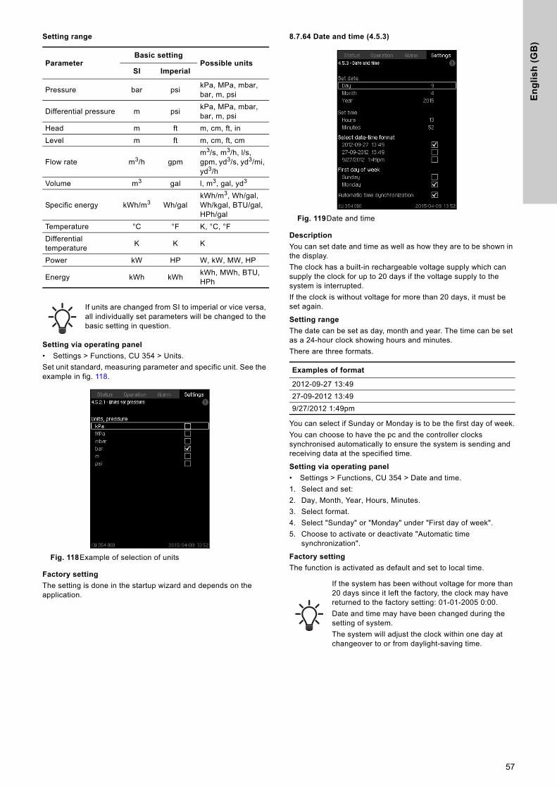
En
gli
sh
(G
B)
Setting range
Setting via operating panel
• Settings > Functions, CU 354 > Units.Set unit standard, measuring parameter and specific unit. See the example in fig. 118.
Fig. 118Example of selection of units
Factory setting
The setting is done in the startup wizard and depends on the application.
8.7.64 Date and time (4.5.3)
Fig. 119Date and time
Description
You can set date and time as well as how they are to be shown in the display.The clock has a built-in rechargeable voltage supply which can supply the clock for up to 20 days if the voltage supply to the system is interrupted.If the clock is without voltage for more than 20 days, it must be set again.
Setting range
The date can be set as day, month and year. The time can be set as a 24-hour clock showing hours and minutes.There are three formats.
You can select if Sunday or Monday is to be the first day of week.You can choose to have the pc and the controller clocks synchronised automatically to ensure the system is sending and receiving data at the specified time.
Setting via operating panel
• Settings > Functions, CU 354 > Date and time.1. Select and set:2. Day, Month, Year, Hours, Minutes.3. Select format.4. Select "Sunday" or "Monday" under "First day of week".5. Choose to activate or deactivate "Automatic time
synchronization".
Factory setting
The function is activated as default and set to local time.
ParameterBasic setting
Possible unitsSI Imperial
Pressure bar psi kPa, MPa, mbar, bar, m, psi
Differential pressure m psi kPa, MPa, mbar, bar, m, psi
Head m ft m, cm, ft, inLevel m ft m, cm, ft, cm
Flow rate m3/h gpmm3/s, m3/h, l/s, gpm, yd3/s, yd3/mi, yd3/h
Volume m3 gal l, m3, gal, yd3
Specific energy kWh/m3 Wh/galkWh/m3, Wh/gal, Wh/kgal, BTU/gal, HPh/gal
Temperature °C °F K, °C, °FDifferential temperature K K K
Power kW HP W, kW, MW, HP
Energy kWh kWh kWh, MWh, BTU, HPh
If units are changed from SI to imperial or vice versa, all individually set parameters will be changed to the basic setting in question.
Examples of format
2012-09-27 13:4927-09-2012 13:499/27/2012 1:49pm
If the system has been without voltage for more than 20 days since it left the factory, the clock may have returned to the factory setting: 01-01-2005 0:00.Date and time may have been changed during the setting of system.The system will adjust the clock within one day at changeover to or from daylight-saving time.
57
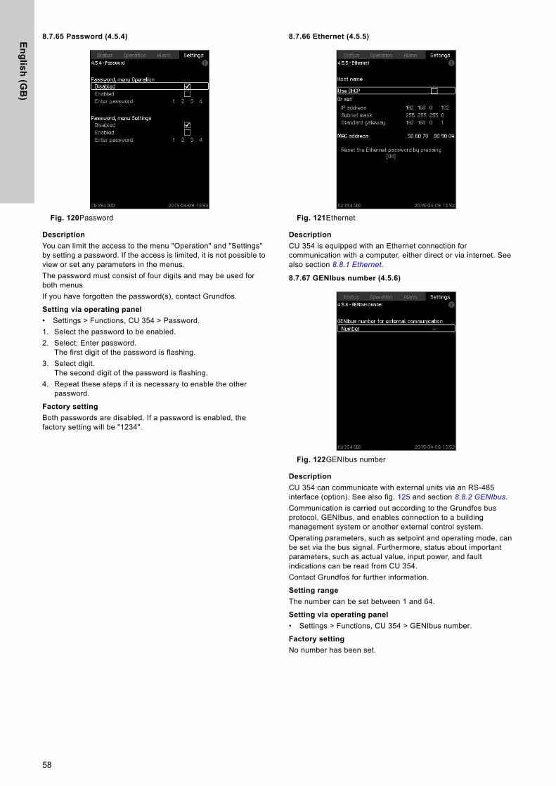
En
glis
h (G
B)
8.7.65 Password (4.5.4)
Fig. 120Password
Description
You can limit the access to the menu "Operation" and "Settings" by setting a password. If the access is limited, it is not possible to view or set any parameters in the menus.The password must consist of four digits and may be used for both menus.If you have forgotten the password(s), contact Grundfos.
Setting via operating panel
• Settings > Functions, CU 354 > Password.1. Select the password to be enabled.2. Select: Enter password.
The first digit of the password is flashing.3. Select digit.
The second digit of the password is flashing.4. Repeat these steps if it is necessary to enable the other
password.
Factory setting
Both passwords are disabled. If a password is enabled, the factory setting will be "1234".
8.7.66 Ethernet (4.5.5)
Fig. 121Ethernet
Description
CU 354 is equipped with an Ethernet connection for communication with a computer, either direct or via internet. See also section 8.8.1 Ethernet.
8.7.67 GENIbus number (4.5.6)
Fig. 122GENIbus number
Description
CU 354 can communicate with external units via an RS-485 interface (option). See also fig. 125 and section 8.8.2 GENIbus.Communication is carried out according to the Grundfos bus protocol, GENIbus, and enables connection to a building management system or another external control system.Operating parameters, such as setpoint and operating mode, can be set via the bus signal. Furthermore, status about important parameters, such as actual value, input power, and fault indications can be read from CU 354.Contact Grundfos for further information.
Setting range
The number can be set between 1 and 64.
Setting via operating panel
• Settings > Functions, CU 354 > GENIbus number.
Factory setting
No number has been set.
58
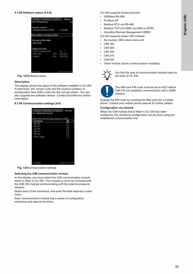
En
gli
sh
(G
B)
8.7.68 Software status (4.5.9)
Fig. 123Software status
Description
The display shows the status of the software installed in CU 354. Furthermore, the version code and the product numbers of configuration files (GSC) read into the unit are shown. You can also upgrade the software version. Contact Grundfos for further information.
8.7.69 Communication settings (4.6)
Fig. 124Communication settings
Selecting the CIM communication module
In this display, you must select the CIM communication module which is fitted in CU 354. This module is not to be confused with the CIM 250 module communicating with the external pressure sensors.Select each of the submenus, and enter the data required in each menu.Each communication module has a series of configuration submenus and special functions.
CU 354 supports these protocols:• GENIbus RS-485• Profibus DP• Modbus RTU via RS-485• Modbus TCP and SMS via GSM or GPRS• Grundfos Remote Management (GRM)CU 354 supports these CIM modules:• No module, DDD stand alone unit• CIM 150• CIM 200• CIM 250• CIM 270• CIM 500• Other module (future communication modules).
Change the PIN code by inserting the SIM card into a mobile phone. Consult your mobile phone manual for further details.
Configuration via network
When the CIM module that is fitted in CU 354 has been configured, the remaining configuration can be done using the established communication line.
You find the type of communication module used on the back of CU 354.
The SIM card PIN code must be set to 4321 before CIM 270 can establish communication with a GSM network.
59
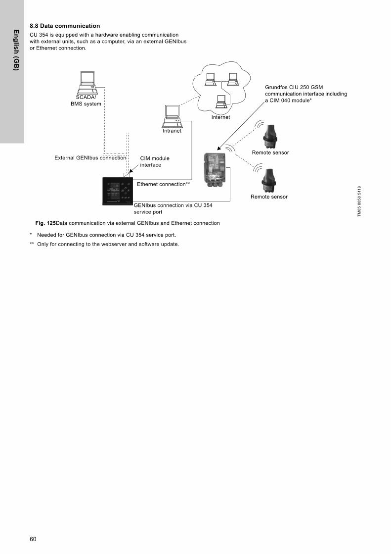
En
glis
h (G
B)
8.8 Data communication
CU 354 is equipped with a hardware enabling communication with external units, such as a computer, via an external GENIbus or Ethernet connection.
Fig. 125Data communication via external GENIbus and Ethernet connection
* Needed for GENIbus connection via CU 354 service port.
** Only for connecting to the webserver and software update.
TM05
805
0 51
18
Intranet
Internet
External GENIbus connection
Ethernet connection**
CIM module interface
Grundfos CIU 250 GSM communication interface including a CIM 040 module*SCADA/
BMS system
GENIbus connection via CU 354 service port
Remote sensor
Remote sensor
60
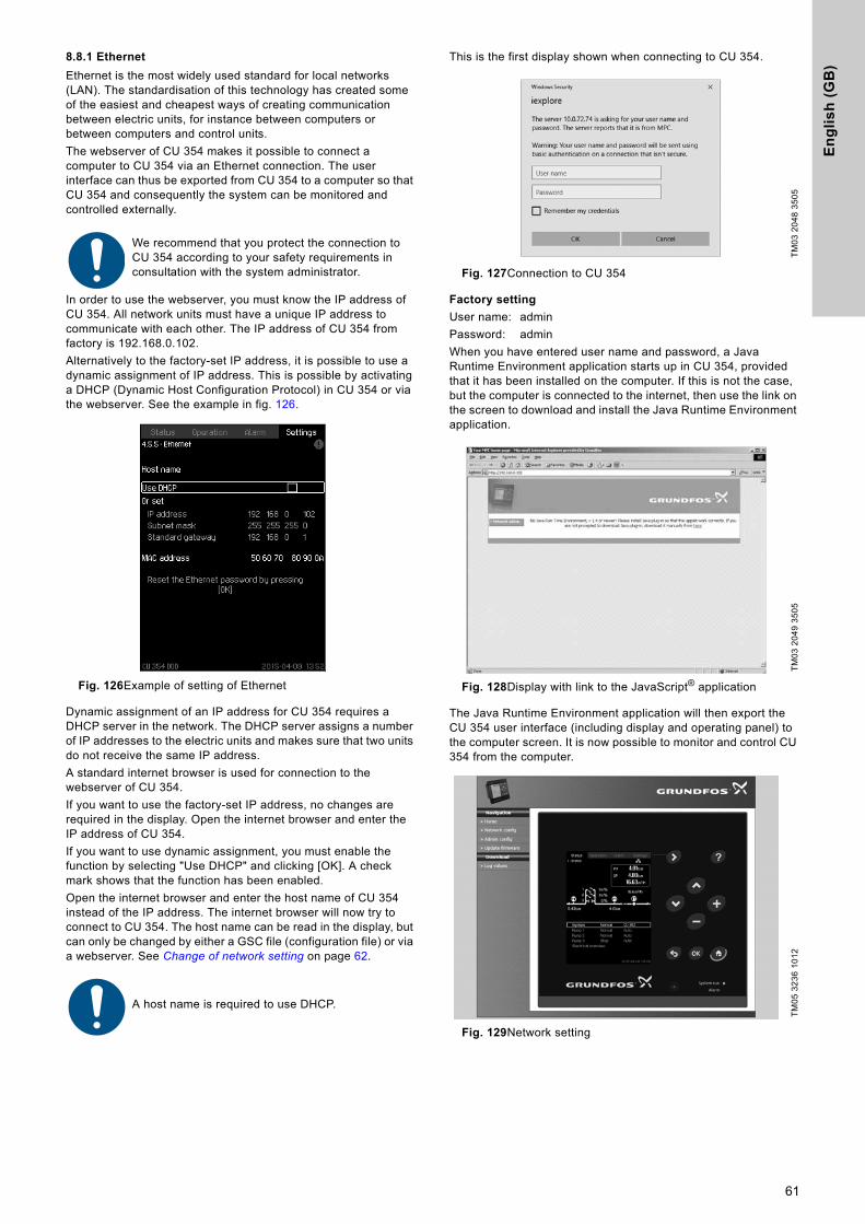
En
gli
sh
(G
B)
8.8.1 Ethernet
Ethernet is the most widely used standard for local networks (LAN). The standardisation of this technology has created some of the easiest and cheapest ways of creating communication between electric units, for instance between computers or between computers and control units.The webserver of CU 354 makes it possible to connect a computer to CU 354 via an Ethernet connection. The user interface can thus be exported from CU 354 to a computer so that CU 354 and consequently the system can be monitored and controlled externally.
In order to use the webserver, you must know the IP address of CU 354. All network units must have a unique IP address to communicate with each other. The IP address of CU 354 from factory is 192.168.0.102.Alternatively to the factory-set IP address, it is possible to use a dynamic assignment of IP address. This is possible by activating a DHCP (Dynamic Host Configuration Protocol) in CU 354 or via the webserver. See the example in fig. 126.
Fig. 126Example of setting of Ethernet
Dynamic assignment of an IP address for CU 354 requires a DHCP server in the network. The DHCP server assigns a number of IP addresses to the electric units and makes sure that two units do not receive the same IP address.A standard internet browser is used for connection to the webserver of CU 354. If you want to use the factory-set IP address, no changes are required in the display. Open the internet browser and enter the IP address of CU 354.If you want to use dynamic assignment, you must enable the function by selecting "Use DHCP" and clicking [OK]. A check mark shows that the function has been enabled.Open the internet browser and enter the host name of CU 354 instead of the IP address. The internet browser will now try to connect to CU 354. The host name can be read in the display, but can only be changed by either a GSC file (configuration file) or via a webserver. See Change of network setting on page 62.
This is the first display shown when connecting to CU 354.
Fig. 127Connection to CU 354
Factory setting
User name: adminPassword: adminWhen you have entered user name and password, a Java Runtime Environment application starts up in CU 354, provided that it has been installed on the computer. If this is not the case, but the computer is connected to the internet, then use the link on the screen to download and install the Java Runtime Environment application.
Fig. 128Display with link to the JavaScript® application
The Java Runtime Environment application will then export the CU 354 user interface (including display and operating panel) to the computer screen. It is now possible to monitor and control CU 354 from the computer.
Fig. 129Network setting
We recommend that you protect the connection to CU 354 according to your safety requirements in consultation with the system administrator.
A host name is required to use DHCP.
TM03
204
8 35
05TM
03 2
049
3505
TM05
323
6 10
12
61
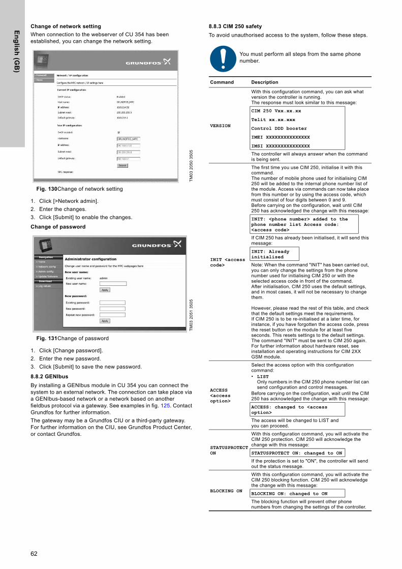
En
glis
h (G
B)
Change of network setting
When connection to the webserver of CU 354 has been established, you can change the network setting.
Fig. 130Change of network setting
1. Click [>Network admin].2. Enter the changes.3. Click [Submit] to enable the changes.
Change of password
Fig. 131Change of password
1. Click [Change password].2. Enter the new password.3. Click [Submit] to save the new password.
8.8.2 GENIbus
By installing a GENIbus module in CU 354 you can connect the system to an external network. The connection can take place via a GENIbus-based network or a network based on another fieldbus protocol via a gateway. See examples in fig. 125. Contact Grundfos for further information.The gateway may be a Grundfos CIU or a third-party gateway. For further information on the CIU, see Grundfos Product Center, or contact Grundfos.
8.8.3 CIM 250 safety
To avoid unauthorised access to the system, follow these steps.
TM03
205
0 35
05TM
03 2
051
3505
You must perform all steps from the same phone number.
Command Description
VERSION
With this configuration command, you can ask what version the controller is running.The response must look similar to this message:
CIM 250 Vxx.xx.xx
Telit xx.xx.xxx
Control DDD booster
IMEI XXXXXXXXXXXXXXX
IMSI XXXXXXXXXXXXXXX
The controller will always answer when the command is being sent.
INIT <access code>
The first time you use CIM 250, initialise it with this command.The number of mobile phone used for initialising CIM 250 will be added to the internal phone number list of the module. Access via commands can now take place from this number or by using the access code, which must consist of four digits between 0 and 9.Before carrying on the configuration, wait until CIM 250 has acknowledged the change with this message:
INIT: <phone number> added to the phone number list Access code: <access code>
If CIM 250 has already been initialised, it will send this message:
INIT: Already initialised
Note: When the command "INIT" has been carried out, you can only change the settings from the phone number used for initialising CIM 250 or with the selected access code in front of the command.After initialisation, CIM 250 uses the default settings, and in most cases, it will not be necessary to change them.
However, please read the rest of this table, and check that the default settings meet the requirements.If CIM 250 is to be re-initialised at a later time, for instance, if you have forgotten the access code, press the reset button on the module for at least five seconds. This resets settings to the default settings. The command "INIT" must be sent to CIM 250 again. For further information about hardware reset, see installation and operating instructions for CIM 2XX GSM module.
ACCESS <access option>
Select the access option with this configuration command:• LIST
Only numbers in the CIM 250 phone number list can send configuration and control messages.
Before carrying on the configuration, wait until the CIM 250 has acknowledged the change with this message:
ACCESS: changed to <access option>
The access will be changed to LIST and you can proceed.
STATUSPROTECT ON
With this configuration command, you will activate the CIM 250 protection. CIM 250 will acknowledge the change with this message:
STATUSPROTECT ON: changed to ON
If the protection is set to "ON", the controller will send out the status message.
BLOCKING ON
With this configuration command, you will activate the CIM 250 blocking function. CIM 250 will acknowledge the change with this message:
BLOCKING ON: changed to ON
The blocking function will prevent other phone numbers from changing the settings of the controller.
62
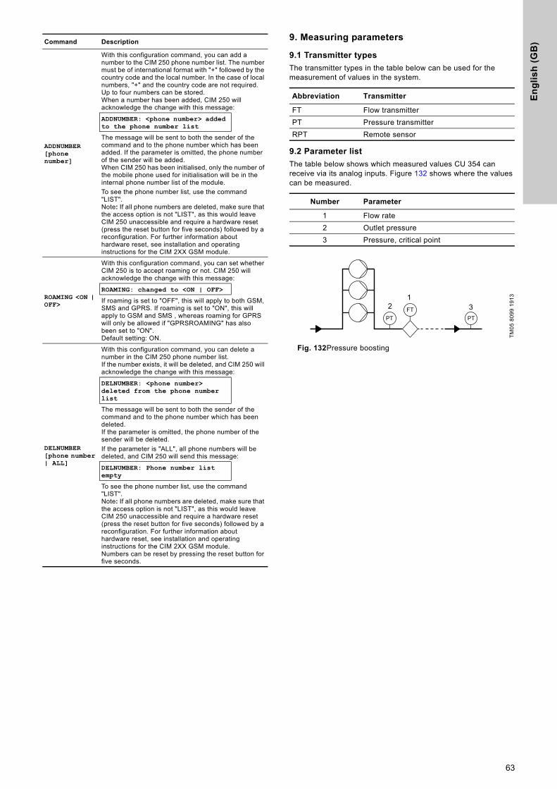
En
gli
sh
(G
B)
9. Measuring parameters9.1 Transmitter types
The transmitter types in the table below can be used for the measurement of values in the system.
9.2 Parameter list
The table below shows which measured values CU 354 can receive via its analog inputs. Figure 132 shows where the values can be measured.
Fig. 132Pressure boosting
ADDNUMBER [phone number]
With this configuration command, you can add a number to the CIM 250 phone number list. The number must be of international format with "+" followed by the country code and the local number. In the case of local numbers, "+" and the country code are not required. Up to four numbers can be stored.When a number has been added, CIM 250 will acknowledge the change with this message:
ADDNUMBER: <phone number> added to the phone number list
The message will be sent to both the sender of the command and to the phone number which has been added. If the parameter is omitted, the phone number of the sender will be added.When CIM 250 has been initialised, only the number of the mobile phone used for initialisation will be in the internal phone number list of the module.To see the phone number list, use the command "LIST".Note: If all phone numbers are deleted, make sure that the access option is not "LIST", as this would leave CIM 250 unaccessible and require a hardware reset (press the reset button for five seconds) followed by a reconfiguration. For further information about hardware reset, see installation and operating instructions for the CIM 2XX GSM module.
ROAMING <ON | OFF>
With this configuration command, you can set whether CIM 250 is to accept roaming or not. CIM 250 will acknowledge the change with this message:
ROAMING: changed to <ON | OFF>
If roaming is set to "OFF", this will apply to both GSM, SMS and GPRS. If roaming is set to "ON", this will apply to GSM and SMS , whereas roaming for GPRS will only be allowed if "GPRSROAMING" has also been set to "ON".Default setting: ON.
DELNUMBER [phone number | ALL]
With this configuration command, you can delete a number in the CIM 250 phone number list.If the number exists, it will be deleted, and CIM 250 will acknowledge the change with this message:
DELNUMBER: <phone number> deleted from the phone number list
The message will be sent to both the sender of the command and to the phone number which has been deleted.If the parameter is omitted, the phone number of the sender will be deleted.If the parameter is "ALL", all phone numbers will be deleted, and CIM 250 will send this message:
DELNUMBER: Phone number list empty
To see the phone number list, use the command "LIST".Note: If all phone numbers are deleted, make sure that the access option is not "LIST", as this would leave CIM 250 unaccessible and require a hardware reset (press the reset button for five seconds) followed by a reconfiguration. For further information about hardware reset, see installation and operating instructions for the CIM 2XX GSM module.Numbers can be reset by pressing the reset button for five seconds.
Command Description
Abbreviation Transmitter
FT Flow transmitterPT Pressure transmitterRPT Remote sensor
Number Parameter
1 Flow rate2 Outlet pressure3 Pressure, critical point
TM05
809
9 19
1312 3
63
En
glis
h (G
B)
10. Servicing the product
10.1 Maintaining the product
10.1.1 CU 354
CU 354 is maintenance-free. Keep the unit clean and dry, and protect it against direct sunlight. For ambient temperature, see section 13. Technical data.
11. Taking the product out of operationSwitch off the main switch to take the system out of operation.
12. Fault finding
WARNING
Electric shock
Death or serious personal injury- Switch off the power supply before you start any
work on the product.- Lock the main switch with a padlock to ensure that
the power supply cannot be accidentally switched on.
WARNING
Electric shock
Death or serious personal injury- Do not touch the conductors in front of the main
switch as they are still energised.- Lock the main switch with a padlock to ensure that
the power supply cannot be accidentally switched on.
WARNING
Electric shock
Death or serious personal injury- Switch off the power supply for at least five
minutes before you start any work on the product.- Make sure that the power supply cannot be
accidentally switched on.
Fault Possible cause Remedy
1. The system has stopped and cannot restart.
a) The primary sensor is defective. Replace the sensor.Transmitters with 0-20 mA or 4-20 mA output signals are monitored by the system.
b) The cable is broken or short-circuited. Repair or replace the cable.c) The power supply is disconnected. Connect the power supply.d) CU 354 is defective. Contact Grundfos.e) The power supply is disconnected. Connect the power supply.f) The main switch is switched off. Switch on the main switch.g) The main switch is defective. Replace the main switch.h) The motor protection is activated. Contact Grundfos.
64
En
gli
sh
(G
B)
13. Technical data13.1 Altitude above sea level
Maximum 1000 m.
13.2 Temperature
Ambient temperature: 0 °C to 40 °C.
13.3 Relative humidity
Maximum relative humidity: 95 %.
14. Electrical data
Supply voltage
See the nameplate of the system.
Backup fuse
See the wiring diagram supplied with the system.
Digital inputs
Analog inputs
Digital outputs (relay outputs)
All digital outputs are potential-free relay contacts.
Inputs for PTC sensor/thermal switch
For PTC sensors according to DIN 44082, thermal switches can also be connected.
15. Further product informationFurther information about Control DDD and the pumps is available in Grundfos Product Center at www.grundfos.com.
16. Disposing of the productThis product or parts of it must be disposed of in an environmentally sound way:1. Use the public or private waste collection service.2. If this is not possible, contact the nearest Grundfos company
or service workshop.The crossed-out wheelie bin symbol on a product means that it must be disposed of separately from household waste. When a product marked with this symbol reaches its end of life, take it to a collection point designated by the local waste disposal
authorities. The separate collection and recycling of such products will help protect the environment and human health.
Open-circuit voltage: 24 VDCClosed-circuit current: 5 mA, DCFrequency range: 0-4 Hz
All digital inputs are supplied with SELV voltage (Safety Extra-Low Voltage).
Input current and voltage: 0-20 mA4-20 mA0-10 V
Tolerance: ± 3.3 % of full scaleRepetitive accuracy: ± 1 % of full scaleInput resistance, current: < 250 ΩInput resistance, voltage, CU 354: 50 kΩ ± 10 %Input resistance, voltage, IO 351: > 50 kΩ ± 10 %Supply to sensor: 24 V, maximum 50 mA,
short-circuit protected
All analog inputs are supplied with SELV voltage (Safety Extra-Low Voltage).
Maximum contact load: 240 VAC, 2 AMinimum contact load: 5 VDC, 10 mA
Some outputs have a common C terminal. For further information, see also the wiring diagram supplied with the system.
Open-circuit voltage: 12 VDC ± 15 %Closed-circuit current: 2.6 mA, DC
Inputs for PTC sensors are electrically separated from the other inputs and outputs of the system.
65

66
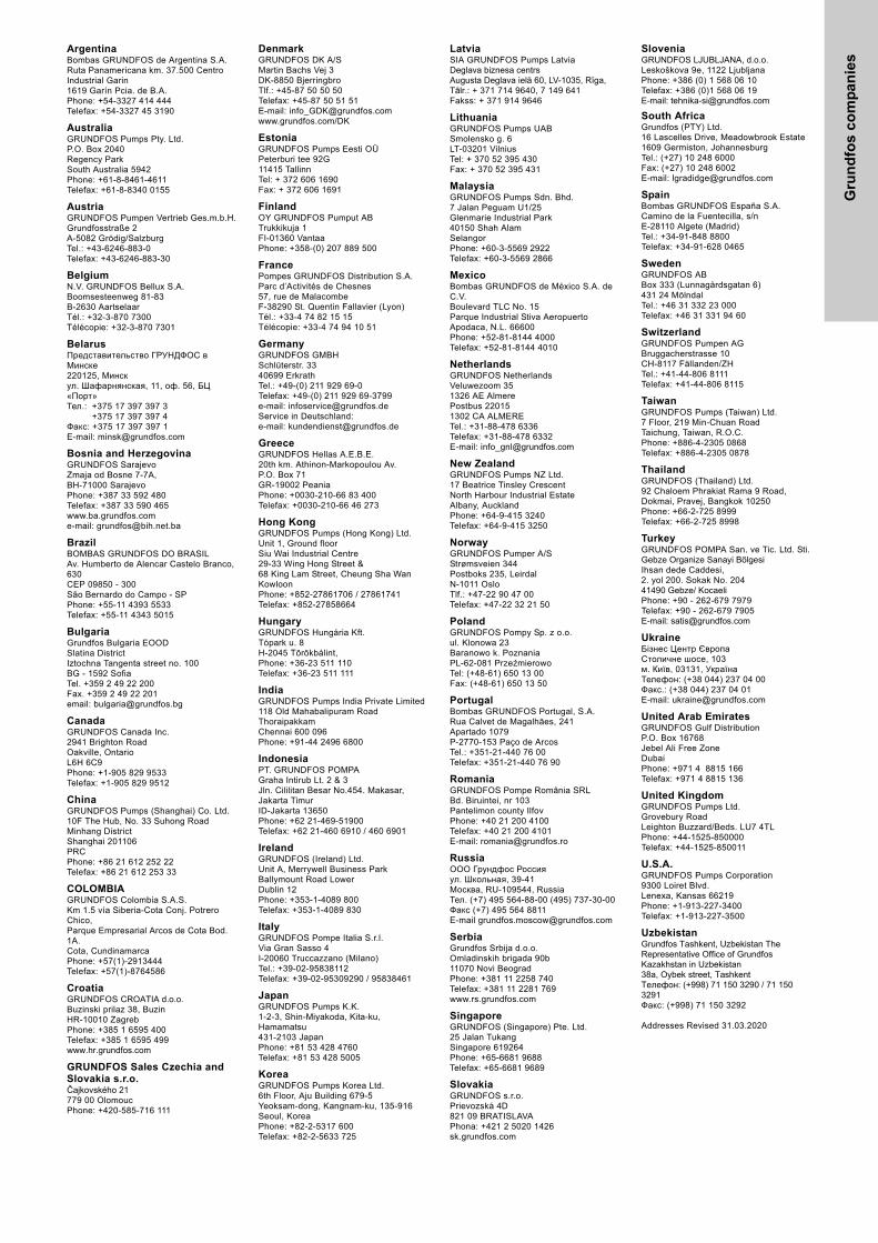
Gru
nd
fos
co
mp
anie
s
ArgentinaBombas GRUNDFOS de Argentina S.A.Ruta Panamericana km. 37.500 Centro Industrial Garin1619 Garín Pcia. de B.A.Phone: +54-3327 414 444Telefax: +54-3327 45 3190
AustraliaGRUNDFOS Pumps Pty. Ltd. P.O. Box 2040 Regency Park South Australia 5942 Phone: +61-8-8461-4611 Telefax: +61-8-8340 0155
AustriaGRUNDFOS Pumpen Vertrieb Ges.m.b.H.Grundfosstraße 2 A-5082 Grödig/Salzburg Tel.: +43-6246-883-0 Telefax: +43-6246-883-30
BelgiumN.V. GRUNDFOS Bellux S.A. Boomsesteenweg 81-83 B-2630 Aartselaar Tél.: +32-3-870 7300 Télécopie: +32-3-870 7301
BelarusПредставительство ГРУНДФОС в Минске220125, Минскул. Шафарнянская, 11, оф. 56, БЦ «Порт»Тел.: +375 17 397 397 3
+375 17 397 397 4Факс: +375 17 397 397 1E-mail: [email protected]
Bosnia and HerzegovinaGRUNDFOS SarajevoZmaja od Bosne 7-7A,BH-71000 SarajevoPhone: +387 33 592 480Telefax: +387 33 590 465www.ba.grundfos.come-mail: [email protected]
BrazilBOMBAS GRUNDFOS DO BRASILAv. Humberto de Alencar Castelo Branco, 630CEP 09850 - 300São Bernardo do Campo - SPPhone: +55-11 4393 5533Telefax: +55-11 4343 5015
BulgariaGrundfos Bulgaria EOODSlatina DistrictIztochna Tangenta street no. 100BG - 1592 SofiaTel. +359 2 49 22 200Fax. +359 2 49 22 201email: [email protected]
CanadaGRUNDFOS Canada Inc. 2941 Brighton Road Oakville, Ontario L6H 6C9 Phone: +1-905 829 9533 Telefax: +1-905 829 9512
ChinaGRUNDFOS Pumps (Shanghai) Co. Ltd.10F The Hub, No. 33 Suhong RoadMinhang DistrictShanghai 201106PRCPhone: +86 21 612 252 22Telefax: +86 21 612 253 33
COLOMBIAGRUNDFOS Colombia S.A.S.Km 1.5 vía Siberia-Cota Conj. Potrero Chico,Parque Empresarial Arcos de Cota Bod. 1A.Cota, CundinamarcaPhone: +57(1)-2913444Telefax: +57(1)-8764586
CroatiaGRUNDFOS CROATIA d.o.o.Buzinski prilaz 38, BuzinHR-10010 ZagrebPhone: +385 1 6595 400 Telefax: +385 1 6595 499www.hr.grundfos.com
GRUNDFOS Sales Czechia and Slovakia s.r.o.Čajkovského 21779 00 OlomoucPhone: +420-585-716 111
DenmarkGRUNDFOS DK A/S Martin Bachs Vej 3 DK-8850 Bjerringbro Tlf.: +45-87 50 50 50 Telefax: +45-87 50 51 51 E-mail: [email protected]/DK
EstoniaGRUNDFOS Pumps Eesti OÜPeterburi tee 92G11415 TallinnTel: + 372 606 1690Fax: + 372 606 1691
FinlandOY GRUNDFOS Pumput AB Trukkikuja 1 FI-01360 Vantaa Phone: +358-(0) 207 889 500
FrancePompes GRUNDFOS Distribution S.A. Parc d’Activités de Chesnes 57, rue de Malacombe F-38290 St. Quentin Fallavier (Lyon) Tél.: +33-4 74 82 15 15 Télécopie: +33-4 74 94 10 51
GermanyGRUNDFOS GMBHSchlüterstr. 3340699 ErkrathTel.: +49-(0) 211 929 69-0 Telefax: +49-(0) 211 929 69-3799e-mail: [email protected] in Deutschland:e-mail: [email protected]
GreeceGRUNDFOS Hellas A.E.B.E. 20th km. Athinon-Markopoulou Av. P.O. Box 71 GR-19002 Peania Phone: +0030-210-66 83 400 Telefax: +0030-210-66 46 273
Hong KongGRUNDFOS Pumps (Hong Kong) Ltd. Unit 1, Ground floor Siu Wai Industrial Centre 29-33 Wing Hong Street & 68 King Lam Street, Cheung Sha Wan Kowloon Phone: +852-27861706 / 27861741 Telefax: +852-27858664
HungaryGRUNDFOS Hungária Kft.Tópark u. 8H-2045 Törökbálint, Phone: +36-23 511 110Telefax: +36-23 511 111
IndiaGRUNDFOS Pumps India Private Limited118 Old Mahabalipuram RoadThoraipakkamChennai 600 096Phone: +91-44 2496 6800
IndonesiaPT. GRUNDFOS POMPAGraha Intirub Lt. 2 & 3Jln. Cililitan Besar No.454. Makasar, Jakarta TimurID-Jakarta 13650Phone: +62 21-469-51900Telefax: +62 21-460 6910 / 460 6901
IrelandGRUNDFOS (Ireland) Ltd. Unit A, Merrywell Business ParkBallymount Road LowerDublin 12 Phone: +353-1-4089 800 Telefax: +353-1-4089 830
ItalyGRUNDFOS Pompe Italia S.r.l. Via Gran Sasso 4I-20060 Truccazzano (Milano)Tel.: +39-02-95838112 Telefax: +39-02-95309290 / 95838461
JapanGRUNDFOS Pumps K.K.1-2-3, Shin-Miyakoda, Kita-ku, Hamamatsu431-2103 JapanPhone: +81 53 428 4760Telefax: +81 53 428 5005
KoreaGRUNDFOS Pumps Korea Ltd.6th Floor, Aju Building 679-5Yeoksam-dong, Kangnam-ku, 135-916Seoul, KoreaPhone: +82-2-5317 600Telefax: +82-2-5633 725
LatviaSIA GRUNDFOS Pumps Latvia Deglava biznesa centrsAugusta Deglava ielā 60, LV-1035, Rīga,Tālr.: + 371 714 9640, 7 149 641Fakss: + 371 914 9646
LithuaniaGRUNDFOS Pumps UABSmolensko g. 6LT-03201 VilniusTel: + 370 52 395 430Fax: + 370 52 395 431
MalaysiaGRUNDFOS Pumps Sdn. Bhd.7 Jalan Peguam U1/25Glenmarie Industrial Park40150 Shah AlamSelangor Phone: +60-3-5569 2922Telefax: +60-3-5569 2866
MexicoBombas GRUNDFOS de México S.A. de C.V. Boulevard TLC No. 15Parque Industrial Stiva AeropuertoApodaca, N.L. 66600Phone: +52-81-8144 4000 Telefax: +52-81-8144 4010
NetherlandsGRUNDFOS NetherlandsVeluwezoom 351326 AE AlmerePostbus 220151302 CA ALMERE Tel.: +31-88-478 6336 Telefax: +31-88-478 6332E-mail: [email protected]
New ZealandGRUNDFOS Pumps NZ Ltd.17 Beatrice Tinsley CrescentNorth Harbour Industrial EstateAlbany, AucklandPhone: +64-9-415 3240Telefax: +64-9-415 3250
NorwayGRUNDFOS Pumper A/S Strømsveien 344 Postboks 235, Leirdal N-1011 Oslo Tlf.: +47-22 90 47 00 Telefax: +47-22 32 21 50
PolandGRUNDFOS Pompy Sp. z o.o.ul. Klonowa 23Baranowo k. PoznaniaPL-62-081 PrzeźmierowoTel: (+48-61) 650 13 00Fax: (+48-61) 650 13 50
PortugalBombas GRUNDFOS Portugal, S.A. Rua Calvet de Magalhães, 241Apartado 1079P-2770-153 Paço de ArcosTel.: +351-21-440 76 00Telefax: +351-21-440 76 90
RomaniaGRUNDFOS Pompe România SRLBd. Biruintei, nr 103 Pantelimon county IlfovPhone: +40 21 200 4100Telefax: +40 21 200 4101E-mail: [email protected]
RussiaООО Грундфос Россияул. Школьная, 39-41Москва, RU-109544, Russia Тел. (+7) 495 564-88-00 (495) 737-30-00Факс (+7) 495 564 8811E-mail [email protected]
Serbia Grundfos Srbija d.o.o.Omladinskih brigada 90b11070 Novi Beograd Phone: +381 11 2258 740Telefax: +381 11 2281 769www.rs.grundfos.com
SingaporeGRUNDFOS (Singapore) Pte. Ltd.25 Jalan Tukang Singapore 619264 Phone: +65-6681 9688 Telefax: +65-6681 9689
SlovakiaGRUNDFOS s.r.o.Prievozská 4D 821 09 BRATISLAVA Phona: +421 2 5020 1426sk.grundfos.com
SloveniaGRUNDFOS LJUBLJANA, d.o.o.Leskoškova 9e, 1122 LjubljanaPhone: +386 (0) 1 568 06 10Telefax: +386 (0)1 568 06 19E-mail: [email protected]
South AfricaGrundfos (PTY) Ltd.16 Lascelles Drive, Meadowbrook Estate1609 Germiston, JohannesburgTel.: (+27) 10 248 6000Fax: (+27) 10 248 6002E-mail: [email protected]
SpainBombas GRUNDFOS España S.A. Camino de la Fuentecilla, s/n E-28110 Algete (Madrid) Tel.: +34-91-848 8800 Telefax: +34-91-628 0465
SwedenGRUNDFOS AB Box 333 (Lunnagårdsgatan 6) 431 24 Mölndal Tel.: +46 31 332 23 000Telefax: +46 31 331 94 60
SwitzerlandGRUNDFOS Pumpen AG Bruggacherstrasse 10 CH-8117 Fällanden/ZH Tel.: +41-44-806 8111 Telefax: +41-44-806 8115
TaiwanGRUNDFOS Pumps (Taiwan) Ltd. 7 Floor, 219 Min-Chuan Road Taichung, Taiwan, R.O.C. Phone: +886-4-2305 0868Telefax: +886-4-2305 0878
ThailandGRUNDFOS (Thailand) Ltd. 92 Chaloem Phrakiat Rama 9 Road,Dokmai, Pravej, Bangkok 10250Phone: +66-2-725 8999Telefax: +66-2-725 8998
TurkeyGRUNDFOS POMPA San. ve Tic. Ltd. Sti.Gebze Organize Sanayi Bölgesi Ihsan dede Caddesi,2. yol 200. Sokak No. 20441490 Gebze/ KocaeliPhone: +90 - 262-679 7979Telefax: +90 - 262-679 7905E-mail: [email protected]
UkraineБізнес Центр ЄвропаСтоличне шосе, 103м. Київ, 03131, Україна Телефон: (+38 044) 237 04 00 Факс.: (+38 044) 237 04 01E-mail: [email protected]
United Arab EmiratesGRUNDFOS Gulf DistributionP.O. Box 16768Jebel Ali Free ZoneDubaiPhone: +971 4 8815 166Telefax: +971 4 8815 136
United KingdomGRUNDFOS Pumps Ltd. Grovebury Road Leighton Buzzard/Beds. LU7 4TL Phone: +44-1525-850000 Telefax: +44-1525-850011
U.S.A.GRUNDFOS Pumps Corporation 9300 Loiret Blvd.Lenexa, Kansas 66219Phone: +1-913-227-3400 Telefax: +1-913-227-3500
UzbekistanGrundfos Tashkent, Uzbekistan The Representative Office of Grundfos Kazakhstan in Uzbekistan38a, Oybek street, TashkentТелефон: (+998) 71 150 3290 / 71 150 3291Факс: (+998) 71 150 3292
Addresses Revised 31.03.2020

98509352 06.2020
ECM: 1282948 Trad
emar
ks d
ispl
ayed
in th
is m
ater
ial,
incl
udin
g bu
t not
lim
ited
to G
rund
fos,
the
Gru
ndfo
s lo
go a
nd “b
e th
ink
inno
vate
” are
regi
ster
ed tr
adem
arks
ow
ned
by T
he G
rund
fos
Gro
up. A
ll rig
hts
rese
rved
.©
202
0 G
rund
fos
Hol
ding
A/S
, all
right
s re
serv
ed.
www.grundfos.com

![For November 2016 - Meetup Blues Songbook.pdf · Robert Johnson, 1939 YouTube video tutorial: [Even down strums with emphasis on the 2nd beats: dDd dDd dDd dDd]](https://img.dokumen.tips/doc/110x75/5ac135a87f8b9a5a4e8cdf48/for-november-2016-meetup-blues-songbookpdfrobert-johnson-1939-youtube-video.jpg)
![DD DDDD...DDDDD DDDDD DDDDD DDD DDD DDD DDD DDDD DDDD DDDD DD DDD 'LYLQD DDDDDD DDDDDDDD DDDDDDDDDDD DDDD 'DWD˛ ˆ ˙ 3DJ ˛ 6L]H˛ D $9(˛ D 7LUDWXUD˛ ˙˝ˇ 'LIIXVLRQH˛ ˝ ˇ](https://img.dokumen.tips/doc/110x75/602cf500d486b733137221b6/dd-dddd-ddddd-ddddd-ddddd-ddd-ddd-ddd-ddd-dddd-dddd-dddd-dd-ddd-lylqd-dddddd.jpg)


![DDD - festivaldispoleto.com€¦ · ddd dd dddd dddd vwurª 'dwd˛ ˘ ˇ 3dj ˛ 6l]h˛ d $9(˛ d 7ludwxud˛ ˙˝ 'liixvlrqh˛ ˆ /hwwrul˛ media 1. 6rusuhvd dddd ddd ddd ddd ddddd](https://img.dokumen.tips/doc/110x75/5fc291774b906303fc518da2/ddd-ddd-dd-dddd-dddd-vwur-dwd-3dj-6lh-d-9-d-7ludwxud-.jpg)