Embed Size (px)
Citation preview
CONTENTS
PT3-1
PT
Co
mp
on
en
t R
efe
ren
ce
Gu
ide
Co
up
ling
sC
lutc
hes
an
d B
rake
sF
LE
XID
YN
EF
luid
Co
up
ling
sT
OR
QU
E-T
AM
ER
Bu
shin
gs
FLEXIDYNE®
Features/Benefits . . . . . . . . . . . . . . . . . . . . . . . . . . . . . . . . . . . . . . . . . . . . . . . . . . . . PT3-2
Specification . . . . . . . . . . . . . . . . . . . . . . . . . . . . . . . . . . . . . . . . . . . . . . . . . . . . . . . . PT3-3
How To Order . . . . . . . . . . . . . . . . . . . . . . . . . . . . . . . . . . . . . . . . . . . . . . . . . . . . . . . PT3-3
Nomenclature . . . . . . . . . . . . . . . . . . . . . . . . . . . . . . . . . . . . . . . . . . . . . . . . . . . . . . . PT3-3
Selection . . . . . . . . . . . . . . . . . . . . . . . . . . . . . . . . . . . . . . . . . . . . . . . . . . . . . . . . . . . PT3-4
Selection/Dimensions FLEXIDYNE Drives . . . . . . . . . . . . . . . . . . . . . . . . . . . . . . . . . . . . . . . . . . . . . . . PT3-8 FLEXIDYNE Couplings . . . . . . . . . . . . . . . . . . . . . . . . . . . . . . . . . . . . . . . . . . . . PT3-9 PH Couplings . . . . . . . . . . . . . . . . . . . . . . . . . . . . . . . . . . . . . . . . . . . . . . . . . . PT3-11 C-FLEX Modules . . . . . . . . . . . . . . . . . . . . . . . . . . . . . . . . . . . . . . . . . . . . . . . PT3-13
Modifications/Accessories . . . . . . . . . . . . . . . . . . . . . . . . . . . . . . . . . . . . . . . . . . . . PT3-15
Engineering/Technical . . . . . . . . . . . . . . . . . . . . . . . . . . . . . . . . . . . . . . . . . . . . . . . . PT3-25
Part Number Index . . . . . . . . . . . . . . . . . . . . . . . . . . . . . . . . . . . . . . . . . . . . . . . . . INDEX-1
Keyword Index . . . . . . . . . . . . . . . . . . . . . . . . . . . . . . . . . . . . . . . . . . . . . . . . . . . INDEX-67

PT3-2
FEATURES/BENEFITSPT
Co
mp
on
en
t R
efe
ren
ce G
uid
eC
ou
plin
gs
Clu
tch
es an
d B
rakesF
LE
XID
YN
EF
luid
Co
up
ling
sT
OR
QU
E-TA
ME
RB
ush
ing
s
FLEXIDYNE
Smoother, Faster Acceleration-- Smaller motors may be used-- Motor starts under no load conditions-- Smoother starts-- Starting torque can be easily customized
More Efficient Design-- Permits use of standard NEMA Design B motors-- High torque or high slip motors not needed-- Reduced voltage starters not needed-- Wound rotor motors not needed
More Efficient Running-- No slip at running speed means no wear, no heat, no power loss
Overload Protection-- Provides overload protection at overloads somewhat greater than starting torque-- Protection devices to prevent damage to FLEXIDYNE are available
Low Current Draw-- Less than twice the nameplate amperage during both starting and overload periods-- Many electric utilities recommend FLEXIDYNE
Increased Productivity-- Eliminates product spillage and machine damage due to harsh starts or jammed loads
PT3-3
PT
Co
mp
on
en
ts
Ref
ere
nc
e G
uid
eC
ou
plin
gs
Clu
tch
es a
nd
Bra
kes
FL
EX
IDY
NE
Flu
id C
ou
plin
gs
TO
RQ
UE
-TA
ME
RB
ush
ing
s
SPECIFICATION/HOW TO ORDER/NOMENCLATURE
SPECIFICATIONFLEXIDYNE is available in three designs: Drives, Couplings, and C-Flex Modules to meet most system needs. The Drive style is designed to mount directly on the motor shaft to provide an extremely compact unit for belted service. The Coupling style provides a versatile solution for transmitting torque between in-line shafts. The C-Flex Module style provides all of the benefits of regular FLEXIDYNE in a compact package that readily mounts between C-Face motors and reducers.
HOW TO ORDER
DRIVE STYLESpecify mechanism size and bore size. Select a sheave from the selection tables found in the Modifications/Accessories section. Refer to the part number when ordering.
COUPLING STYLEOn size 5C - specify bore size. A complete coupling consists of (1) output hub and (1) mechanism.
On larger sizes - specify coupling size, and bore size. A complete coupling consists of (1) mechanism, including flexible disc, (1) Poly-Disc flange, and (2) bushings.
Type PH Couplings - specify coupling size, bore size of the driven end and the motor end. A complete coupling consists of (1) mechanism, (1) Taper-Lock or Bored-To-Size flange assembly, and (1) element.
Refer to the part numbers when ordering.
C-FLEX MODULE STYLESpecify the C-Flex unit size and the FLEXIDYNE mechanism. Refer to the part numbers when ordering.
FLOW CHARGEDetermine the amount of flow charge to be ordered by referring to the Flow Charge tables in the Modifications/Accessories section. Choose between cast steel and stainless. Refer to the part number when ordering.
FLEXIDYNE
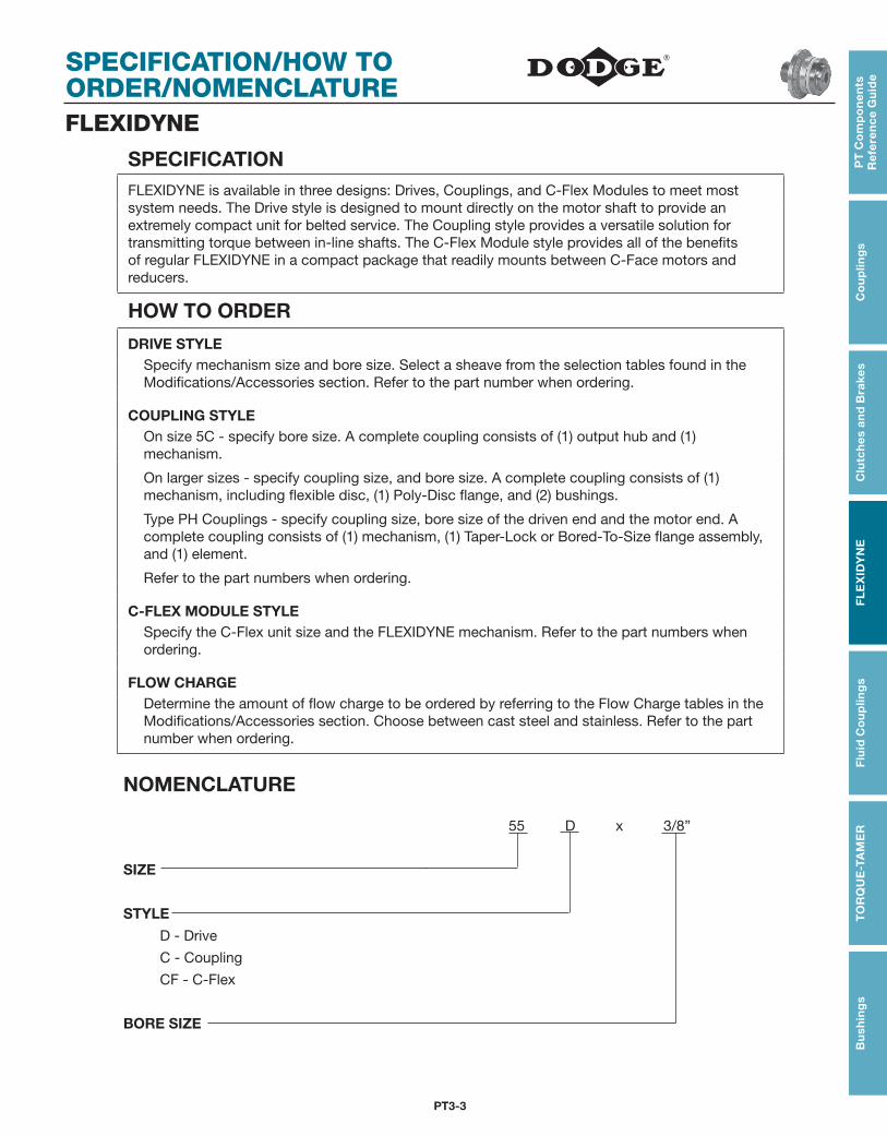
NOMENCLATURE 55 D x 3/8”
SIZE
STYLE
D - Drive
C - Coupling
CF - C-Flex
BORE SIZE

PT3-4
SELECTIONPT
Co
mp
on
en
t R
efe
ren
ce G
uid
eC
ou
plin
gs
Clu
tch
es an
d B
rakesF
LE
XID
YN
EF
luid
Co
up
ling
sT
OR
QU
E-TA
ME
RB
ush
ing
s
FEATURES/BENEFITS PAGE PT3-2
SPECIFICATION PAGE PT3-3
SELECTION/DIMENSIONS PAGE PT3-8
ENGINEERING/TECHNICAL PAGE PT3-26
FLEXIDYNE
SIMPLIFIED SELECTION PROCEDUREThe tables on pages PT3-6 -PT3-7 give FLEXIDYNE mechanism size and amount of flow charge to provide starting capacities from 100-200% of motor nameplate HP of a NEMA Design B squirrel cage induction motor. This starting capacity is satisfactory for most ordinary industrial applications.
The FLEXIDYNE unit sizes shown in the simplified selec tion tables suggest the most economical FLEXIDYNE mechanism for a given RPM and HP. In some cases, under the same conditions, there may be other sizes of FLEXIDYNE which may be utilized.
STEP 1Determine the approximate starting torque percentage for the application. As a guide, suggested percentages are listed in the table below.
STEP 2Determine motor speed and HP to be used. Refer to tables on pages PT3-6 -PT3-7 based on 1760, 1175, or 875 RPM NEMA Design B motors.
STEP 3Check maximum bore from Selection/Dimensions pages.
FLEXIDYNE Mechanism Starting TorqueApplication Range Application Range Application Range
Air Conditioning 130-175% Cranes (Bridge Draw) 150-200% Mixers 130-150%
Agitators 130-175% Crushers 150-200% Oven Drivers 150-175%
Belt Conveyors 130-150% Dryers 130-175% Paper Mills
Blenders 130-175% Fans 150-175% Agitator 130-175%
Blowers 150-175% Lumber Chippers 150-200% Hydropulper 130-175%
Bucket Elevators 130-175% Sawdust Conv. 130-175% Chipper 150-200%
Can Filling Machine 125-150% Matl. Handling Equip. 130-150% Drier 130-150%
Compressors 150-175% Mills (Ball, Pebble) 150-175% Pumps 125-150%
NOTE: Since FLEXIDYNE Drives and Couplings are selected primarily as torque limiting devices by using the starting torque percentages shown above, the use of a service factor is not necessary.
SELECTION
PT3-5
PT
Co
mp
on
en
t R
efe
ren
ce
Gu
ide
Co
up
ling
sC
lutc
hes
an
d B
rake
sF
LE
XID
YN
EF
luid
Co
up
ling
sT
OR
QU
E-T
AM
ER
Bu
shin
gs
FEATURES/BENEFITS PAGE PT3-2
SPECIFICATION PAGE PT3-3
SELECTION/DIMENSIONS PAGE PT3-8
ENGINEERING/TECHNICAL PAGE PT3-26
FLEXIDYNEOTHER APPLICATIONS
The information on the previous page provides a simple method of selecting the FLEXIDYNE mechanism size when used with NEMA Design B motors under general operating conditions. Selection for any other application is based on the specific conditions and requirements of the installation. The power transmitting characteristics of the FLEXIDYNE unit vary with input speed and amount of flow charge used. A FLEXIDYNE unit can be adapted to the specific conditions and requirements of the individual application by using the proper amount of flow charge.
FLEXIDYNE units are not recommended for variable speed applications, engines or speeds below 700 RPM.
DODGE engineers welcome inquiries on FLEXIDYNE mechanism selection for applications not previously cov ered. It is suggested that their experience be called upon to recommend the best installation. To contact Dodge engineering please call 864-284-5700.
Please provide the following information with your request:
Type, HP, RPM, shaft size of motor
Type, RPM, shaft size of driven machine
Frequency of starts, reversals, and overloads
Time required to accelerate
For high inertia loads, WR2
Starting HP and Overload Breakaway HP desired
Functions the FLEXIDYNE unit must perform
PT3-6
SELECTIONPT
Co
mp
on
en
t R
efe
ren
ce G
uid
eC
ou
plin
gs
Clu
tch
es an
d B
rakesF
LE
XID
YN
EF
luid
Co
up
ling
sT
OR
QU
E-TA
ME
RB
ush
ing
s
FEATURES/BENEFITS PAGE PT3-2
SPECIFICATION PAGE PT3-3
SELECTION/DIMENSIONS PAGE PT3-8
ENGINEERING/TECHNICAL PAGE PT3-26
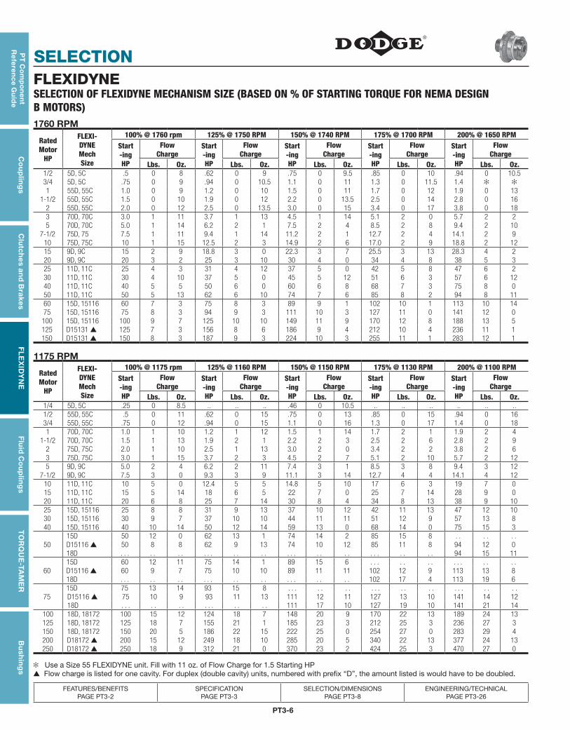
FLEXIDYNESELECTION OF FLEXIDYNE MECHANISM SIZE (BASED ON % OF STARTING TORQUE FOR NEMA DESIGN B MOTORS)1760 RPM
RatedMotor
HP
FLEXI-DYNEMechSize
100% @ 1760 rpm 125% @ 1750 RPM 150% @ 1740 RPM 175% @ 1700 RPM 200% @ 1650 RPMStart-ingHP
FlowCharge
Start-ingHP
FlowCharge
Start-ingHP
FlowCharge
Start-ingHP
FlowCharge
Start-ingHP
FlowCharge
Lbs. Oz. Lbs. Oz. Lbs. Oz. Lbs. Oz. Lbs. Oz.1/2 5D, 5C .5 0 8 .62 0 9 .75 0 9.5 .85 0 10 .94 0 10.53/4 5D, 5C .75 0 9 .94 0 10.5 1.1 0 11 1.3 0 11.5 1.4 ✻ ✻1 55D, 55C 1.0 0 9 1.2 0 10 1.5 0 11 1.7 0 12 1.9 0 13
1-1/2 55D, 55C 1.5 0 10 1.9 0 12 2.2 0 13.5 2.5 0 14 2.8 0 162 55D, 55C 2.0 0 12 2.5 0 13.5 3.0 0 15 3.4 0 17 3.8 0 183 70D, 70C 3.0 1 11 3.7 1 13 4.5 1 14 5.1 2 0 5.7 2 25 70D, 70C 5.0 1 14 6.2 2 1 7.5 2 4 8.5 2 8 9.4 2 10
7-1/2 75D, 75 7.5 1 11 9.4 1 14 11.2 2 1 12.7 2 4 14.1 2 910 75D, 75C 10 1 15 12.5 2 3 14.9 2 6 17.0 2 9 18.8 2 1215 9D, 9C 15 2 9 18.8 3 0 22.3 3 7 25.5 3 13 28.3 4 220 9D, 9C 20 3 2 25 3 10 30 4 0 34 4 8 38 5 325 11D, 11C 25 4 3 31 4 12 37 5 0 42 5 8 47 6 230 11D, 11C 30 4 10 37 5 0 45 5 12 51 6 3 57 6 1240 11D, 11C 40 5 5 50 6 0 60 6 8 68 7 3 75 8 050 11D, 11C 50 5 13 62 6 10 74 7 6 85 8 2 94 8 1160 15D, 15116 60 7 3 75 8 3 89 9 1 102 10 1 113 10 1475 15D, 15116 75 8 3 94 9 3 111 10 3 127 11 0 141 12 0
100 15D, 15116 100 9 7 125 10 10 149 11 9 170 12 8 188 13 5125 D15131 ▲ 125 7 3 156 8 6 186 9 4 212 10 4 236 11 1150 D15131 ▲ 150 8 3 187 9 3 224 10 3 255 11 1 283 12 1
1175 RPM
RatedMotor
HP
FLEXI-DYNEMechSize
100% @ 1175 rpm 125% @ 1160 RPM 150% @ 1150 RPM 175% @ 1130 RPM 200% @ 1100 RPMStart-ingHP
FlowCharge
Start-ingHP
FlowCharge
Start-ingHP
FlowCharge
Start-ingHP
FlowCharge
Start-ingHP
FlowCharge
Lbs. Oz. Lbs. Oz. Lbs. Oz. Lbs. Oz. Lbs. Oz.1/4 5D, 5C .25 0 8.5 .. .. .. .46 0 10.5 .. .. .. .. .. ..1/2 55D, 55C .5 0 11 .62 0 15 .75 0 13 .85 0 15 .94 0 163/4 55D, 55C .75 0 12 .94 0 15 1.1 0 16 1.3 0 17 1.4 0 181 70D, 70C 1.0 1 10 1.2 1 12 1.5 1 14 1.7 2 1 1.9 2 4
1-1/2 70D, 70C 1.5 1 13 1.9 2 1 2.2 2 3 2.5 2 6 2.8 2 92 75D, 75C 2.0 1 10 2.5 1 13 3.0 2 0 3.4 2 2 3.8 2 63 75D, 75C 3.0 1 15 3.7 2 3 4.5 2 7 5.1 2 10 5.7 2 125 9D, 9C 5.0 2 4 6.2 2 11 7.4 3 1 8.5 3 8 9.4 3 12
7-1/2 9D, 9C 7.5 3 0 9.3 3 9 11.1 3 14 12.7 4 4 14.1 4 1210 11D, 11C 10 5 0 12.4 5 5 14.8 5 10 17 6 3 19 7 015 11D, 11C 15 5 14 18 6 5 22 7 0 25 7 14 28 9 020 11D, 11C 20 6 8 25 7 14 30 8 4 34 8 13 38 9 1025 15D, 15116 25 8 8 31 9 13 37 10 12 42 11 13 47 12 1030 15D, 15116 30 9 7 37 10 10 44 11 11 51 12 9 57 13 840 15D, 15116 40 10 14 50 12 14 59 13 0 68 14 0 75 15 3
5015D 50 12 0 62 13 1 74 14 2 85 15 8 . . . . . .D15116 ▲ 50 8 8 62 9 13 74 10 12 85 11 8 94 12 018D . . . . . . . . . . . . . . . . . . . . . . . . . . . . 94 15 11
6015D 60 12 11 75 14 1 89 15 6 . . . . . . . . . . . . . .D15116 ▲ 60 9 7 75 10 10 89 11 11 102 12 9 113 13 818D . . . . . . . . . . . . . . . . . . . . . 102 17 4 113 19 6
7515D 75 13 14 93 15 8 . . . . . . . . . . . . . . . . . . . . .D15116 ▲ 75 10 9 93 11 13 111 12 11 127 13 10 141 14 1218D . . . . . . . . . . . . . . 111 17 10 127 19 10 141 21 14
100 18D, 18172 100 15 12 124 18 7 148 20 9 170 22 13 189 24 13125 18D, 18172 125 18 7 155 21 1 185 23 3 212 25 3 236 27 3150 18D, 18172 150 20 5 186 22 15 222 25 0 254 27 0 283 29 4200 D18172 ▲ 200 15 12 249 18 10 285 20 5 340 22 13 377 24 13250 D18172 ▲ 250 18 9 312 21 0 370 23 2 424 25 3 470 27 0
✻ Use a Size 55 FLEXIDYNE unit. Fill with 11 oz. of Flow Charge for 1.5 Starting HP▲ Flow charge is listed for one cavity. For duplex (double cavity) units, numbered with prefix “D”, the amount listed is would have to be doubled.

SELECTION
PT3-7
PT
Co
mp
on
en
t R
efe
ren
ce
Gu
ide
Co
up
ling
sC
lutc
hes
an
d B
rake
sF
LE
XID
YN
EF
luid
Co
up
ling
sT
OR
QU
E-T
AM
ER
Bu
shin
gs
FEATURES/BENEFITS PAGE PT3-2
SPECIFICATION PAGE PT3-3
SELECTION/DIMENSIONS PAGE PT3-8
ENGINEERING/TECHNICAL PAGE PT3-26
FLEXIDYNESELECTION OF FLEXIDYNE MECHANISM SIZE (BASED ON % OF STARTING TORQUE FOR NEMA DESIGN B MOTORS)875 RPM
RatedMotor
HP
FLEXI-DYNEMechSize
100% @ 875 rpm 125% @ 870 RPM 150% @ 850 RPM 175% @ 840 RPM 200% @ 820 RPMStart-ingHP
FlowCharge
Start-ingHP
FlowCharge
Start-ingHP
FlowCharge
Start-ingHP
FlowCharge
Start-ingHP
FlowCharge
Lbs. Oz. Lbs. Oz. Lbs. Oz. Lbs. Oz. Lbs. Oz.1/2 70D, 70C .5 1 12 .62 1 15 .75 2 1 .85 2 4 .94 2 63/4 70D, 70C .75 2 0 .94 2 3 1.1 2 6 1.3 2 8 1.4 2 121 75D, 75C 1.0 1 13 1.2 2 0 1.5 2 3 1.7 2 7 1.9 2 8
1-1/2 75D, 75C 1.5 2 2 1.9 2 7 2.2 2 10 2.5 2 11 2.8 2 122 9D, 9C 2.0 2 6 2.5 2 12 2.9 3 0 3.4 3 8 3.7 3 123 9D, 9C 3.0 3 0 3.7 3 8 4.4 4 0 5.0 4 6 5.6 4 145 11D, 11C 5.0 5 6 6.2 5 14 7.3 6 10 8.4 7 0 9.4 7 8
7-1/2 11D, 11C 7.5 6 8 9.3 7 2 10.9 8 0 12.6 8 8 14.0 9 510 15D, 15116 10 8 6 12.4 9 8 14.6 10 9 16.8 11 7 18.7 12 515 15D, 15116 15 10 5 19 11 7 22 12 8 25 13 5 28 14 620 15D, 15116 20 11 12 25 12 13 29 13 14 34 15 1 38 15 825 D15116 25 9 7 31 10 9 36 11 11 42 12 8 47 13 530 D15116 30 10 5 37 11 7 44 12 8 50 13 5 56 14 640 18D, 18172 40 15 3 50 18 0 58 20 6 67 22 8 75 24 750 18D, 18172 50 17 14 62 20 4 73 22 14 84 24 14 94 26 1460 18D, 18172 60 19 13 75 22 6 87 24 15 101 26 1 112 28 1275 D18172 ▲ 75 14 8 93 17 2 109 19 11 126 21 13 141 23 12
100 D18172 ▲ 100 17 14 124 20 4 146 22 14 168 24 14 187 26 14125 D18172 ▲ 125 20 2 155 22 13 182 25 7 210 27 4 234 29 4
▲ Flow charge is listed for one cavity. For duplex (double cavity) units, numbered with prefix “D”, the amount listed would have to be doubled.

PT3-8
SELECTION/DIMENSIONSPT
Co
mp
on
en
t R
efe
ren
ce G
uid
eC
ou
plin
gs
Clu
tch
es an
d B
rakesF
LE
XID
YN
EF
luid
Co
up
ling
sT
OR
QU
E-TA
ME
RB
ush
ing
s
FEATURES/BENEFITS PAGE PT3-2
SPECIFICATION PAGE PT3-3
SELECTION PAGE PT3-4
ENGINEERING/TECHNICAL PAGE PT3-26
FLEXIDYNE Drives
.16 1.72
.06 .63
.81
.38
DIA.4.81
DIA.PITCH
4L3.0-5L3.4
1.50
SIZE 5D
A
CD
E
B
G
F
SIZE 55D
H
F
G
BE
SIZE 9D
A
H
B
F
E
D
G
SIZES 70D/75D & 11D THRU 18D
CD A
Each FLEXIDYNE, including a container of flow charge, is individually packaged. Cutout features and a cross section drawing are shown in the Modifications/Accessories section.
NOTE: Drawings are for dimensional purpose only and do not necessarily represent construction
5D FLEXIDYNE DriveNom.Stock
Bores ▲
w/IntegralSheave
P.D.
PartNumber
Wt.Lbs. Keyseat Key
Req’d.
5/84L2.2-5L2.6 305106 3.44L3.0-5L3.4 305101 2.4 3/16 X 3/32 X 1-11/16 3/16 X 3/16 X 1-3/84L3.6-5L4.0 305102 3.6
3/4(Max.)
4L3.0-5L3.4 305103 2.7 3/16 X 3/32 X 1-11/16 3/16 X 3/16 X 1-7/8
▲ +.0005” +.0025” over nominal. Bores not listed will be quoted on application.
SELECTION/DIMENSIONS
PT3-9
PT
Co
mp
on
en
t R
efe
ren
ce
Gu
ide
Co
up
ling
sC
lutc
hes
an
d B
rake
sF
LE
XID
YN
EF
luid
Co
up
ling
sT
OR
QU
E-T
AM
ER
Bu
shin
gs
FEATURES/BENEFITS PAGE PT3-2
SPECIFICATION PAGE PT3-3
SELECTION PAGE PT3-4
ENGINEERING/TECHNICAL PAGE PT3-26
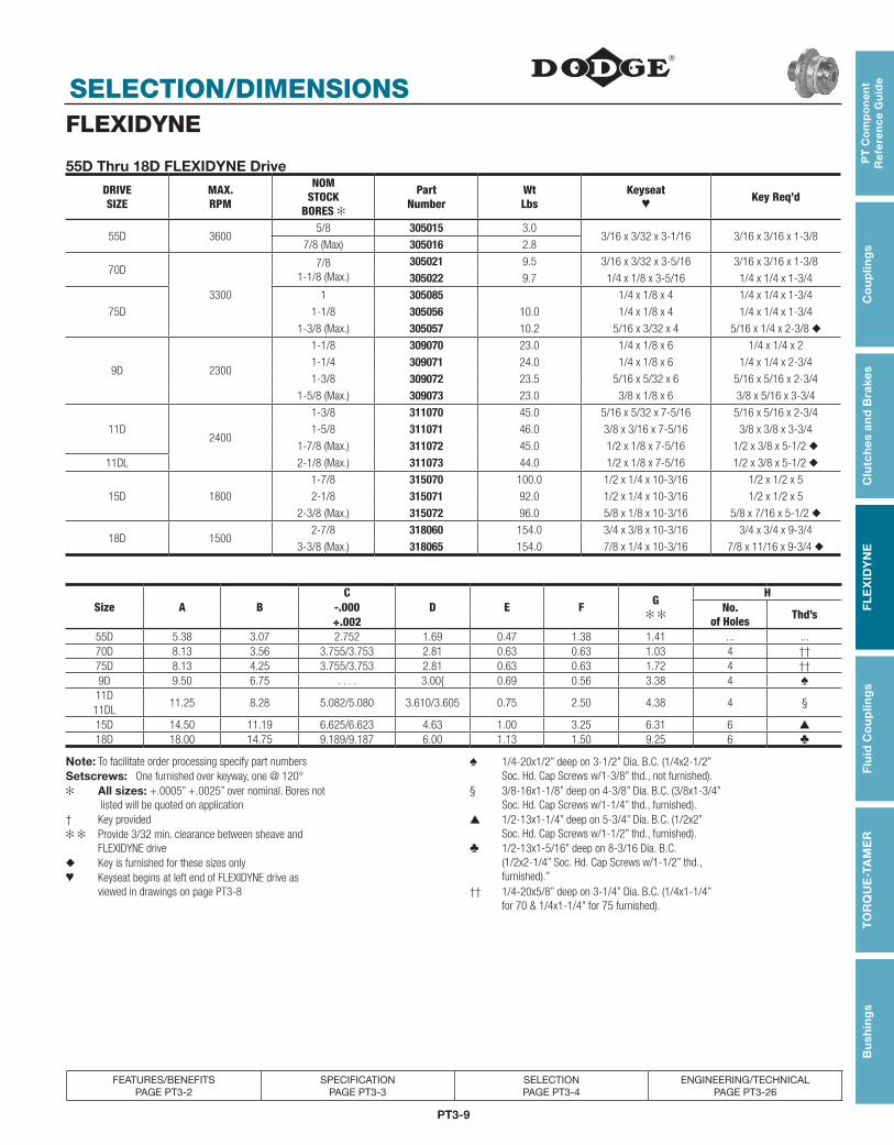
55D Thru 18D FLEXIDYNE Drive
DRIVE SIZE
MAX.RPM
NOMSTOCK
BORES ✻
PartNumber
WtLbs
Keyseat♥
Key Req’d
55D 36005/8 305015 3.0
3/16 x 3/32 x 3-1/16 3/16 x 3/16 x 1-3/87/8 (Max) 305016 2.8
70D
3300
7/81-1/8 (Max.)
305021 9.5 3/16 x 3/32 x 3-5/16 3/16 x 3/16 x 1-3/8
305022 9.7 1/4 x 1/8 x 3-5/16 1/4 x 1/4 x 1-3/4
75D
1 305085 1/4 x 1/8 x 4 1/4 x 1/4 x 1-3/4
1-1/8 305056 10.0 1/4 x 1/8 x 4 1/4 x 1/4 x 1-3/4
1-3/8 (Max.) 305057 10.2 5/16 x 3/32 x 4 5/16 x 1/4 x 2-3/8 ◆
9D 2300
1-1/8 309070 23.0 1/4 x 1/8 x 6 1/4 x 1/4 x 2
1-1/4 309071 24.0 1/4 x 1/8 x 6 1/4 x 1/4 x 2-3/4
1-3/8 309072 23.5 5/16 x 5/32 x 6 5/16 x 5/16 x 2-3/4
1-5/8 (Max.) 309073 23.0 3/8 x 1/8 x 6 3/8 x 5/16 x 3-3/4
11D2400
1-3/8 311070 45.0 5/16 x 5/32 x 7-5/16 5/16 x 5/16 x 2-3/4
1-5/8 311071 46.0 3/8 x 3/16 x 7-5/16 3/8 x 3/8 x 3-3/4
1-7/8 (Max.) 311072 45.0 1/2 x 1/8 x 7-5/16 1/2 x 3/8 x 5-1/2 ◆
11DL 2-1/8 (Max.) 311073 44.0 1/2 x 1/8 x 7-5/16 1/2 x 3/8 x 5-1/2 ◆
15D 1800
1-7/8 315070 100.0 1/2 x 1/4 x 10-3/16 1/2 x 1/2 x 5
2-1/8 315071 92.0 1/2 x 1/4 x 10-3/16 1/2 x 1/2 x 5
2-3/8 (Max.) 315072 96.0 5/8 x 1/8 x 10-3/16 5/8 x 7/16 x 5-1/2 ◆
18D 15002-7/8 318060 154.0 3/4 x 3/8 x 10-3/16 3/4 x 3/4 x 9-3/4
3-3/8 (Max.) 318065 154.0 7/8 x 1/4 x 10-3/16 7/8 x 11/16 x 9-3/4 ◆
Size A BC
D E F G✻ ✻
H-.000 No.
of Holes Thd’s+.002
55D 5.38 3.07 2.752 1.69 0.47 1.38 1.41 ... ...70D 8.13 3.56 3.755/3.753 2.81 0.63 0.63 1.03 4 ††75D 8.13 4.25 3.755/3.753 2.81 0.63 0.63 1.72 4 ††9D 9.50 6.75 . . . . 3.00{ 0.69 0.56 3.38 4 ♠
11D11.25 8.28 5.082/5.080 3.610/3.605 0.75 2.50 4.38 4 §
11DL15D 14.50 11.19 6.625/6.623 4.63 1.00 3.25 6.31 6 ▲
18D 18.00 14.75 9.189/9.187 6.00 1.13 1.50 9.25 6 ♣
Note: To facilitate order processing specify part numbers ♠ 1/4-20x1/2” deep on 3-1/2” Dia. B.C. (1/4x2-1/2” Soc. Hd. Cap Screws w/1-3/8” thd., not furnished).Setscrews: One furnished over keyway, one @ 120°
✻ All sizes: +.0005” +.0025” over nominal. Bores not listed will be quoted on application
§ 3/8-16x1-1/8” deep on 4-3/8” Dia. B.C. (3/8x1-3/4” Soc. Hd. Cap Screws w/1-1/4” thd., furnished).
† Key provided ▲ 1/2-13x1-1/4” deep on 5-3/4” Dia. B.C. (1/2x2” Soc. Hd. Cap Screws w/1-1/2” thd., furnished).✻ ✻ Provide 3/32 min. clearance between sheave and
FLEXIDYNE drive ♣ 1/2-13x1-5/16” deep on 8-3/16 Dia. B.C. (1/2x2-1/4” Soc. Hd. Cap Screws w/1-1/2” thd., furnished).”
◆ Key is furnished for these sizes only♥ Keyseat begins at left end of FLEXIDYNE drive as viewed in drawings on page PT3-8 †† 1/4-20x5/8” deep on 3-1/4” Dia. B.C. (1/4x1-1/4”
for 70 & 1/4x1-1/4” for 75 furnished).
FLEXIDYNE
PT3-10
SELECTION/DIMENSIONSPT
Co
mp
on
en
t R
efe
ren
ce G
uid
eC
ou
plin
gs
Clu
tch
es an
d B
rakesF
LE
XID
YN
EF
luid
Co
up
ling
sT
OR
QU
E-TA
ME
RB
ush
ing
s
FEATURES/BENEFITS PAGE PT3-2
SPECIFICATION PAGE PT3-3
SELECTION PAGE PT3-4
ENGINEERING/TECHNICAL PAGE PT3-26
FLEXIDYNE
OUTPUT HUB
.13
2.94
.94
4.81 2.19
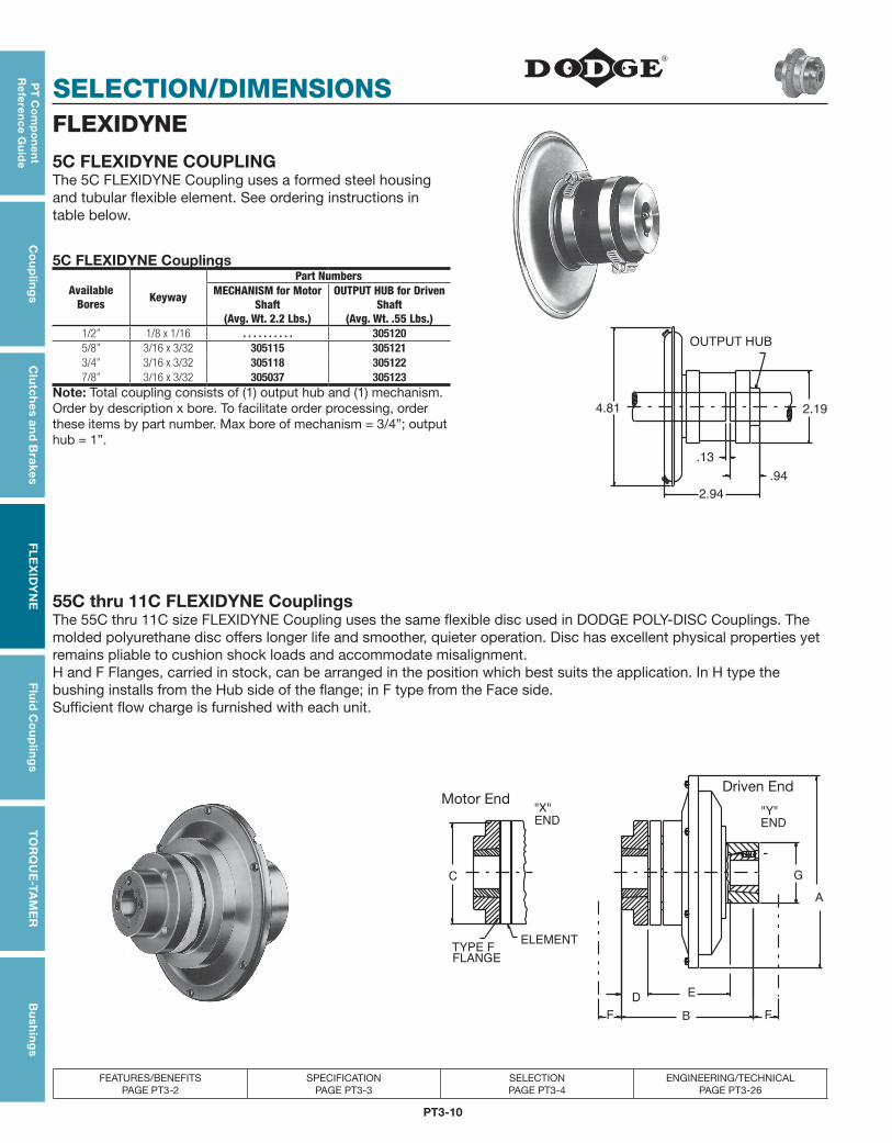
5C FLEXIDYNE COUPLINGThe 5C FLEXIDYNE Coupling uses a formed steel housing and tubular flexible element. See ordering instructions in table below.
55C thru 11C FLEXIDYNE CouplingsThe 55C thru 11C size FLEXIDYNE Coupling uses the same flexible disc used in DODGE POLY-DISC Couplings. The molded polyurethane disc offers longer life and smoother, quieter operation. Disc has excellent physical properties yet remains pliable to cushion shock loads and accommodate misalignment.H and F Flanges, carried in stock, can be arranged in the position which best suits the application. In H type the bushing installs from the Hub side of the flange; in F type from the Face side.Sufficient flow charge is furnished with each unit.
ELEMENT
FLANGETYPE F
END
"X"
C
END
"Y"
F FB
DE
A
G
5C FLEXIDYNE Couplings
AvailableBores Keyway
Part NumbersMECHANISM for Motor
Shaft (Avg. Wt. 2.2 Lbs.)
OUTPUT HUB for Driven Shaft
(Avg. Wt. .55 Lbs.)1/2” 1/8 x 1/16 . . . . . . . . . . 3051205/8” 3/16 x 3/32 305115 3051213/4” 3/16 x 3/32 305118 3051227/8” 3/16 x 3/32 305037 305123
Note: Total coupling consists of (1) output hub and (1) mechanism. Order by description x bore. To facilitate order processing, order these items by part number. Max bore of mechanism = 3/4”; output hub = 1”.
Motor EndDriven End

SELECTION/DIMENSIONS
PT3-11
PT
Co
mp
on
en
t R
efe
ren
ce
Gu
ide
Co
up
ling
sC
lutc
hes
an
d B
rake
sF
LE
XID
YN
EF
luid
Co
up
ling
sT
OR
QU
E-T
AM
ER
Bu
shin
gs
FEATURES/BENEFITS PAGE PT3-2
SPECIFICATION PAGE PT3-3
SELECTION PAGE PT3-4
ENGINEERING/TECHNICAL PAGE PT3-26
FLEXIDYNE55C Thru 11C FLEXIDYNE Couplings
Cplg.Size
Bore Range of Bushing
Max.RPM
Cplg. Less Bushings
Items required for Complete Coupling †Mechanism
(Includes disc)Poly-Disc Flange w/o Bush. Bushings
Size
TYPE H TYPE FWt. Lbs.
Motor End Driven End
Min. Max. Wt. Lbs.
PartNo.
Wt.Lbs.
PartNo.
PartNo.
BushNo.
Avg.Wt.Lbs.
BushNo.
Avg.Wt.Lbs.
55C 1/2 1 1800 5.0 305019 4.0 2-5/8 008057 008058 1.0 1008 .2 1008 .270C ✻ ✻ 1800 15.6 305025 13.6 4 008041 008040 2.0 1215 .7 1610 .775C 1/2 1-11/16 1800 18.6 305058 14.1 5-1/4 008043 008042 4.5 1615 1.0 1610 .79C 1/2 2-11/16 1800 40.6 309074 30.6 7 008045 008044 10.0 2517 2.8 2517 2.811C 1/2 2-11/16 1800 57.2 311074 44.2 8 008047 008046 13.0 2517 2.8 2517 2.8
Complete coupling consists of (1) Mechanism, including flexible disc, (1) POLY-DISC Flange, and two bushings. TAPER-LOCK bushings sold separately.† To facilitate order processing specify part numbers. Determine whether H or F Flange is required and order accordingly. ✻ Motor End: 1/2” -1-1/4” (Min./Max.); Driven End: 1/2” - 1-5/8”◆ Normal dimension. Shaft end float which increases or decreases “E” by slight amounts is permissible.★ 1” on driven end, 1-1/2” on motor end.▲ Space required to loosen bushing with shortened hex key using screws as jack screws-no puller required.Keyways-See tables below for standard keyways and shallow keyways.
Standard KeywaysBore Range Keyway
1/2 - 9/16 Incl. 1/8 x 1/16
over 9/16 - 7/8 Incl. 3/16 x 3/32
over 7/8 - 1-1/4 Incl. 1/4 x 1/8
over 1-1/4 - 1-3/8 Incl. 5/16 x 5/32
over 1-3/8 - 1-3/4 Incl. 3/8 x 3/16
over 1-3/4 - 2-1/4 Incl. 1/2 x 1/4
over 2-1/4 - 2-3/4 Incl. 5/8 x 5/16
over 2-3/4 - 3-1/4 Incl. 3/4 x 3/8
over 3-1/4 - 3-3/4 Incl. 7/8 x 7/16
over 3-3/4 - 4-1/2 Incl. 1 x 1/2
over 4-1/2 - 5-1/2 Incl. 1-1/4 x 5/8
over 5-1/2 - 6-1/2 Incl. 1-1/2 x 3/4
Shallow KeywaysBush No. Bore Range
Note: Key furnished for these exceptions only.
1008 15/16 - 1
16101-9/16 - 11-1/16
1615
2517 2-5/16 - 2-11/16Note: Key furnished for these exceptions only.

PT3-12
SELECTION/DIMENSIONSPT
Co
mp
on
en
t R
efe
ren
ce G
uid
eC
ou
plin
gs
Clu
tch
es an
d B
rakesF
LE
XID
YN
EF
luid
Co
up
ling
sT
OR
QU
E-TA
ME
RB
ush
ing
s
FEATURES/BENEFITS PAGE PT3-2
SPECIFICATION PAGE PT3-3
SELECTION PAGE PT3-4
ENGINEERING/TECHNICAL PAGE PT3-26
TYPE PH FLEXIDYNE COUPLINGSThis unique combination of PARA-FLEX coupling and FLEXIDYNE mechanism offers maximum protection for motors and driven machines. The FLEXIDYNE unit allows the motor to accelerate quickly and start the load smoothly while the Para-Flex coupling permits up to 1° angular misalignment, up to 1/16” parallel misalignment and 3/32” end float. Consequently, starting torque can be tailored to the driven load requirements while torsional and lateral vibration and shock loads are being absorbed or cushioned.
The driven end of the couplings uses TAPER-LOCK bushings only. However, the motor end is available as bushed or bored-to-size. Bored-to-size flanges accommodate larger shafts than possible with bushed flanges. Smaller size flanges are reversible offering the H and F position from the same flange. A choice of H or F flanges is offered for size PX140.
TAPER-LOCK Bushings
Cplg.Size
For Mechanism
ForFlange Assy.
NoAvg.Wt
Lbs.No.
Avg.Wt.Lbs.
987 2517 2.8 1610 0.71196 2517 2.8 2012 1.415116 3030 7.4 2517 2.8
D15116 3030 7.4 2517 2.8D15131 3030 7.4 2517 2.818172 3535 11.5 3535 11.5
D18172 3535 11.5 3535 11.5Note: For Keyway information, see footnote next page
Type PH FLEXIDYNE Couplings W/ TAPER-LOCK Flanges
Cplg.Size
Cplg. Less
Bush-ings ◆
Items Req’d. for Complete Coupling ▲
Mechanism TAPER-LOCK FLG. ASSY ELEMENT
Wt.Lbs.
Driven EndBore Range
PartNo.
Wt.Lbs.
Motor EndBore Range
Size
Part Nos. for Respective Types
Wt.Lbs. Size Part
No.Wt.lbs.
Min. Max. Min. Max.St’d.
(Revers-ible)
Type H Type F
987 46.7 1/2 2-11/16 309077† 40 1/2 1-11/16 PX70 010603 . . . . . . . . . . . . 5.1 PH87 011227 1.61196 65.5 1/2 2-11/16 311077 56 1/2 2-1/8 PX80 010604 . . . . . . . . . . . . 7.4 PH96 011228 2.115116 137.5 1-5/16 3-1/4 315073 120 1/2 2-11/16 PX100 010606 . . . . . . . . . . . . 15.0 PH116 011230 2.5
D15116 184.5 1-5/16 3-1/4 315074 167 1/2 2-11/16 PX100 010606 . . . . . . . . . . . . 15.0 PH116 011230 2.5D15131 175.7 1-5/16 3-1/4 315075 150 1/2 2-11/16 PX110 010607 . . . . . . . . . . . . 21.6 PH131 011231 4.118172 314.2 1-3/16 3-15/16 318110 242 1-3/16 3-15/16 PX140 . . . . . . 011134 011154 64.0 PH172 011234 8.2
D18172 320.2 1-3/16 3-15/16 318400 248 1-3/16 3-15/16 PX140 . . . . . . 011134 011154 64.0 PH172 011234 8.2◆ When ordering bushings, specify bore and part number. ▲ To facilitate order processing specify part numbers. In sizes 18172
and D18172, determine whether H or F Flange is required and order accordingly. Complete Coupling consists of (1) Mechanism, (1) Taper-Lock Flange Assembly, (1) Element and (2) Bushings.
† Assembled-to-order. Consult DODGE for delivery.
Note: Complete Coupling consists of (1) Mechanism, (1) BBS Flange Assembly, (1) Element and (1) Bushing.
◆ Approximate weight with maximum bore★ -.010 to -.015” no keyway
♥ Bored per order-Sizes PX70 thru PX110 are furnished with a clearance fit from nominal bores (up to 2” +.000-.000. over 2” +.0015 -.0000). In PX140 size, tolerance will be applied to custom bores (up to 3” +.000 -.001. over 3” thru 6” +.0000 -.0015; over 6” +.000 -.002). Largest Bore listed should be considered as maximum.
BS Flg.Size
BoreRange
Keyway
NOTE-Key furnished for these exceptions only
PX70PX80PX100PX110
2 - 2-1/8 1/2 x 1/82-3/8 - 2-9/16 5/8 x 3/163-1/16 - 3-1/4 3/4 x 3/16
✪ One furnished over keyway. 3-11/16 - 3-3/4 7/8 x 1/4
♣ Not furnished unless specified on order.3-13/16 - 3-15/16
1 x 1/4
✻ Standard keyway is the same as shown on page. For shallow keyway exceptions, see table at right:NOTE: Taper-Lock bushings sold separately
Cplg.Size
Coupling LessBushings ◆
BBS FLANGE ASSEMBLY
Size
Rough Stock Bore Fin. Bored w St’d. K. W. Rgh. Bored Fin. Bored
Min. Bore★
PartNumber
Wt.Lbs.
Motor EndBore Range
♥
Wt.Lbs.◆
Set ScrewWt.Lbs.
Wt.Lbs.
987 49.5 47.3 PX70BBS
0
010301 7.9 1/2 - 2-1/8 5.7
✪
1196 69.1 66.3 PX80BBS 010302 11 1/2 - 2-9/16 8.215116 147.5 139.5 PX100BBS 010304 25 1/2 - 3-1/4 17
D15116 194.5 186.5 PX100BBS 010304 25 1/2 - 3-1/4 17D15131 189.1 176.1 PX110BBS 010305 35 1/2 - 3-15/16 2218172 336.2 311.2 PX140BBS 2-1/4 010530 86 2-3/4 - 4-1/2 61
♣D18172 342.2 317.2 PX140BBS 2-1/4 010530 86 2-3/4 - 4-1/2 61
FLEXIDYNE
SELECTION/DIMENSIONS
PT3-13
PT
Co
mp
on
en
t R
efe
ren
ce
Gu
ide
Co
up
ling
sC
lutc
hes
an
d B
rake
sF
LE
XID
YN
EF
luid
Co
up
ling
sT
OR
QU
E-T
AM
ER
Bu
shin
gs
FEATURES/BENEFITS PAGE PT3-2
SPECIFICATION PAGE PT3-3
SELECTION PAGE PT3-4
ENGINEERING/TECHNICAL PAGE PT3-26
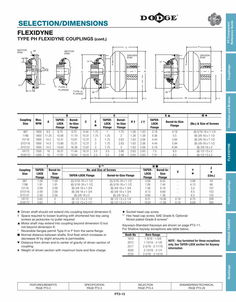
FLEXIDYNETYPE PH FLEXIDYNE COUPLINGS (cont.)
H
H
WG
K
T
U
FLANGE
TYPE F
TYPE H
FLANGE
END
DRIVEN
U
Z
K
JE
M
G W
AC
B
Y
U
M
C
G W
B
JE
Z
A
Y
K
END
DRIVEN
MOTOR
END
MMOTOR
END
B
Coupling Size
Max. RPM A
B
C E ♣
G
H † J †
K ▲ M ◆TAPER-LOCK
Flange
Bored-to-Size Flange
TAPER-LOCK
Flange
Bored-to-Size Flange
TAPER-LOCK
Flange
Bored-to-Size Flange (No.) & Size of Screws
987 1800 9.5 8.75 9.75 9.44 1.75 1 1.75 1.06 1.63 3.19 4.19 (8) 5/16-18 x 1-1/41196 1800 11.25 10.06 11.19 10.31 1.75 1.25 2 1.38 1.38 4.38 5.5 (6) 3/8-16 x 1-1/2
15116 1800 14.5 12.31 13.81 12.31 3 1.75 2.63 1.63 2.06 4.44 5.94 (8) 3/8-16 x 1-1/2D15116 1800 14.5 13.88 15.31 12.31 3 1.75 2.63 1.63 2.06 4.44 5.94 (8) 3/8-16 x 1-1/2D15131 1800 14.5 14.63 16.38 13.81 3 1.75 3 1.63 2.06 5.19 6.94 (8) 3/8-16 x 218172 1500 18 16.31 17.44 18.31 3.5 3.5 3.88 2.63 2.63 7.5 8.5 (8) 1/2-13 x 2
D18172 1500 18 17.81 18.94 18.31 3.5 3.5 3.88 2.63 2.63 7.31 8.5 (8) 1/2-13 x 2
Coupling Size
T U ** W ■
X Y ♥
Z♠
(Lbs.)
TAPER-LOCK
Flange
Bored-to-Size
Flange
No. and Size of Screws TAPER-LOCK
Flange
Bored-to-Size
FlangeTAPER-LOCK Flange Bored-to-Size Flange
987 1.59 1.59 (5) 5/16-18 x 1-1/2 (5) 5/16-18 x 1-1/2 5.94 6.25 . . 3.88 431196 1.91 1.91 (6) 5/16-18 x 1-1/2 (6) 5/16-18 x 1-1/2 7.06 7.44 . . 4.13 66
15116 2.09 2.09 (6) 3/8-16 x 1-3/4 (6) 3/8-16 x 1-3/4 7.56 8.19 . . 5.5 107D15116 2.09 2.09 (6) 3/8-16 x 1-3/4 (6) 3/8-16 x 1-3/4 9.13 9.69 . . 6.5 153D15131 2.56 2.56 (6) 3/8-16 x 2 (6) 3/8-16 x 2 9.88 1.38 . . 6.5 15318172 3.63 3 (8) 1/2-13 x 2-1/2 (8) 1/2-13 x 2-1/4 9.31 10.06 0.19 6.75 209
D18172 3.63 3 (8) 1/2-13 x 2-1/2 (8) 1/2-13 x 2-1/4 10.81 11.56 0.19 6.69 284
♣ Driven shaft should not extend into coupling beyond dimension E. ◆ Socket head cap screw.† Space required to loosen bushing with shortened hex key using screws as jackscrew no puller required
** Hex head cap screw, SAE Grade 8; Optional: Nickel plated Grade 8 screws”
▲ Motor shaft may extend into coupling beyond dimension G but not beyond dimension K. Keyways-Standard Keyways are shown on page PT3-11.
For Shallow keyway exceptions see table below.* Reversible flanges permit Type H or F from the same flange.■ Normal distance between shafts. End float which increases or decreases W by slight amounts is permissible.
Bush No Bore Range
NOTE - Key furnished for these exceptions only. See TAPER-LOCK section for Keyway information
1610 1-9/16 - 1-5/8♥ Distance from driven end to center of gravity of driven section of coupling.
2012 1-15/16 - 2-1/82517 2-5/16 - 2-11/16
♠ Weight of driven section with maximum bore and flow charge. 3030 2-13/16 - 3-1/43535 3-5/16 - 3-15/16

PT3-14
SELECTION/DIMENSIONSPT
Co
mp
on
en
t R
efe
ren
ce G
uid
eC
ou
plin
gs
Clu
tch
es an
d B
rakesF
LE
XID
YN
EF
luid
Co
up
ling
sT
OR
QU
E-TA
ME
RB
ush
ing
s
FEATURES/BENEFITS PAGE PT3-2
SPECIFICATION PAGE PT3-3
SELECTION PAGE PT3-4
ENGINEERING/TECHNICAL PAGE PT3-26
FLEXIDYNEC-FLEX MODULEC-Flex is a system for easily adapting stock FLEXIDYNE couplings to conventional AC motor/C-Face reducer drive combinations. The advantages of this low cost arrangement include soft start and intermittent overload protection utilizing popular NEMA-B motors and across-the-line switching. Costly reduced voltage starters or specially wound motors are not required. FLEXIDYNE unit operates bi-directionally
(reversing) and allows starting of heavy inertial loads without oversized motors.
C-Flex fits all standard NEMA C-Face mountings of 56C, 140TC, 180TC and 210TC frame utilized on 1/2 thru 10 HP, 1750 ROM AC motors. The C-Flex output bearing provides support for single-bearing reducer types, but is equally suitable for reducers having two input shaft bearings.
4.81
.13
2.94
.94
2.19
F1
D
A
F
E
H BOLTS MODULE
CB
C1
OUTPUT HUB
G
C-Flex ModulesHP Rating @ 1750
RPM
For NEMA C-Face Frame
C-Flex Unit ▲ FLEXIDYNE MechanismA B C
Dia.C1Dia. D
Nom.E.
Dia.F F1
GDia.B.C.
H BoltsModel
No.Part No.
Wt.(Lbs.) Size Part
No.Wt.
(Lbs.) No. Size
1/256C 150 305026 14.5 5CF x 5/8 ■ 305117 2.2 4.75 6.63
4.500 4.5016.69 5/8
.1000.19 5.88 4
★
3/44.497 4.503 .160
11
140TC 200 305027 14.5 5CF x 7/8 ■ 305037 2 4.75 6.634.500 4.501
6.81 7/8.100
0.19 5.88 41-1/24.497 4.503 .160
23
180TC 500 305028 54.5 70C 305025 13.6 12.5 108.499 8.500
15.31 1-1/8.200
0.22 7.25 4*
5 8.497 8.502 .2507-1/2
210TC 1000 305029 58.2 75C 305058 14.1 12.5 108.499 8.500
15.84 1-3/8.200
0.22 7.25 410 8.497 8.502 .250
SELECTION DATA-For 1/2 thru 2 HP rating, see table below. ▲ Includes all necessary parts except mechanism.For 3 thru 10 HP rating, see tables on page PT3-6 and PT3-7 ★ 3/8 -16 x 1-1/4 Hex Hd. Cap Screw.■ For 5C FLEXIDYNES see page PT3-10. * 1/2 -13 x 1-1/2 Soc. Hd. Cap Screw.
Selection Of 5CF FLEXIDYNE Mechanism Used In C-Flex Module
RatedMotor
HP
100% @ 1760 RPM 125% @ 1750 RPM 150% @ 1740 RPM 175% @ 1700 RPM 200% @ 1650 RPMStarting HP
Flow Charge Starting HP
Flow Charge Starting HP
Flow Charge Starting HP
Flow Charge Starting HP
Flow Charge
Lbs. Oz. Lbs. Oz. Lbs. Oz. Lbs. Oz. Lbs. Oz.
1/2 .50 0 4 .62 0 5 .75 0 5 .85 0 6 .94 0 73/4 .75 0 5 1.00 0 6 1.10 0 6 1.30 0 7 1.40 0 81 1.00 0 6 1.20 0 7 1.50 0 7 1.70 0 8 1.90 0 9
1-1/2 1.50 0 7 1.90 0 8 2.20 0 8 2.50 0 9 2.80 0 102 2.00 0 8 2.50 0 9 3.00 0 9 3.40 0 10 3.60 0 11

PT3-15
PT
Co
mp
on
en
t R
efe
ren
ce
Gu
ide
Co
up
ling
sC
lutc
hes
an
d B
rake
sF
LE
XID
YN
EF
luid
Co
up
ling
sT
OR
QU
E-T
AM
ER
Bu
shin
gs
MODIFICATIONS/ACCESSORIES
FEATURES/BENEFITS PAGE PT3-2
SPECIFICATION PAGE PT3-3
SELECTION PAGE PT3-4
ENGINEERING/TECHNICAL PAGE PT3-26
FLEXIDYNEFLEXIDYNE Flow Charge
Cast steel flow charge is furnished unless otherwise specified. Sufficient amounts for all applications are furnished and included in the price of each FLEXIDYNE unit. The part numbers listed here apply only when extra flow charge is ordered or the application requires stainless steel flow charge.
Flow charge is packaged in a tough transparent plastic bottle which is graduated and has a handy pour spout. This makes handling of flow charge easy whether pouring into the unit or removing flow charge if a change in torque is desired.
Stainless steel flow charge is recommended for applications subject to excessive moisture, humidity or wide temperature variations that may cause internal condensation. It may be ordered to replace that in an existing unit or in place of the cast steel flow charge when ordering a FLEXIDYNE unit.
Sizes 5, 5CF, and 55 FLEXIDYNE mechanisms use SAE S110 (.0234, maximum diameter) steel shot. In sizes 70 and up, SAE S170 (.0331” maximum diameter) steel shot is used.
Flow Charge for Individual Bulk FLEXIDYNE Flow ChargeFLEXIDYNE Mechanism Applications Size 70 and Up
FLEXIDYNE Mech. Size
▲
Cast Steel Stainless SteelWt.
(Lbs.)Cast SteelPart No.
StainlessPart No.Part No. Wt. Part No. Wt.
5, 5CF 311124 1 lb.-2 oz. 311116 11 oz. 15 . . . . . 311112
55, 6* 311124 1 lb.-2 oz. 311122 1 lb. - 2oz. 20 315111 . . . . .
7* 311125 3 lb.-5 oz. 311118 1 lb. -14 oz. 25 . . . . . 311113
8* 311125 3 lb.-5 oz. 311119 3 lb. -5 oz.
70, 75” 311125 3 lb.-5 oz. 311123 2 lb. -13 oz.
9 309111 5 lb.-3 oz. 311120 5 lb. -3 oz.
11 311111 10 lb. 311121 10 lb.
15 315111 20 lb. (2) 311121 20 lb.
D15, 18(1) 315111
30 lb. (3) 311121 30 lb.(1) 311111
D18 (3) 315111 60 lb.(2) 311113
60 lb.(1) 311121
▲ Units with “D” prefix have duplex cavities.
* Old style FLEXIDYNE sizes.
PT3-16
MODIFICATIONS/ACCESSORIESP
T C
om
po
ne
nt
Re
fere
nc
e Gu
ide
Co
up
ling
sC
lutc
hes a
nd
Brakes
FL
EX
IDY
NE
Flu
id C
ou
plin
gs
TO
RQ
UE
-TAM
ER
Bu
shin
gs
FEATURES/BENEFITS PAGE PT3-2
SPECIFICATION PAGE PT3-3
SELECTION PAGE PT3-4
ENGINEERING/TECHNICAL PAGE PT3-26
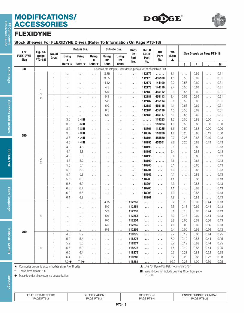
Stock Sheaves For FLEXIDYNE Drives (Refer To Information On Page PT3-18)
For FLEXIDYNE
Size
Fig. No. (page
PT3-18)
No. of Grvs.
Datum Dia. Outside Dia. Bolt- On
Part No.
TAPER LOCK Part No.
QD Part No.
Wt. (Lbs)
▲
See Drwg’s on Page PT3-18Using
A Belts ★
Using B
Belts ★
Using C
Belts ★
Using 3V
Belts
Using 5V
Belts E F L M5D Sheaves are integral - included in price & wt. of assembled unit
55D
1or2
1 . . . . . . . . . 3.35 . . . . . . 112175 . . . . . . 1.1 . . . . 0.69 . . . . 0.31
1 . . . . . . . . . 3.65 . . . . . . 112176 455108 1.5 0.56 0.69 . . . . 0.31
1 . . . . . . . . . 4.12 . . . . . . 112177 144109 2.2 0.56 0.69 . . . . 0.31
1 . . . . . . . . . 4.5 . . . . . . 112178 144110 2.4 0.56 0.69 . . . . 0.31
1 . . . . . . . . . 5.0 . . . . . . 112180 455112 2.9 0.56 0.69 . . . . 0.31
1 . . . . . . . . . 5.3 . . . . . . 112181 455113 3.4 0.56 0.69 . . . . 0.31
1 . . . . . . . . . 5.6 . . . . . . 112182 455114 3.8 0.56 0.69 . . . . 0.31
1 . . . . . . . . . 6.0 . . . . . . 112183 455115 4.1 0.56 0.69 . . . . 0.31
1 . . . . . . . . . 6.5 . . . . . . 112184 455116 4.5 0.56 0.69 . . . . 0.31
1 . . . . . . . . . 6.9 . . . . . . 112185 455117 5.1 0.56 0.69 . . . . 0.31
1or2
1 3.0 3.4 ■ . . . . . . . . . . . . . . . . . . 118283 1.2 0.50 0.88 0.00 . . . .
1 3.2 3.6 ■ . . . . . . . . . . . . . . . . . . 118284 1.3 0.50 0.88 0.00 0.00
1 3.4 3.8 ■ . . . . . . . . . . . . 118301 118285 1.6 0.50 0.88 0.00 0.00
1 3.6 4.0 ■ . . . . . . . . . . . . 118302 118286 1.8 0.25 0.88 0.19 0.00
1 3.8 4.2 ■ . . . . . . . . . . . . 118194 455550 2.2 0.25 0.88 0.19 0.13
1 4.0 4.4 ■ . . . . . . . . . . . . 118195 455551 2.6 0.25 0.88 0.19 0.13
1 4.2 4.6 . . . . . . . . . . . . 118196 . . . . . . 2.1 . . . . 0.88 . . . . 0.13
1 4.4 4.8 . . . . . . . . . . . . 118197 . . . . . . 2.4 . . . . 0.88 . . . . 0.13
1 4.6 5.0 . . . . . . . . . . . . 118198 . . . . . . 3.6 . . . . 0.88 . . . . 0.13
1 4.8 5.2 . . . . . . . . . . . . 118199 . . . . . . 3.8 . . . . 0.88 . . . . 0.13
1 5.0 5.4 . . . . . . . . . . . . 118200 . . . 3.1 . . . . . . 0.88 . . . . 0.13
1 5.2 5.6 . . . . . . . . . . . . 118201 . . . 4.3 . . . . . . 0.88 . . . . 0.13
1 5.4 5.8 . . . . . . . . . . . . 118202 . . . 4.1 . . . . . . 0.88 . . . . 0.13
1 5.6 6.0 . . . . . . . . . . . . 118203 . . . 4.1 . . . . . . 0.88 . . . . 0.13
1 5.8 6.2 . . . . . . . . . . . . 118204 . . . 4.3 . . . 0.88 . . . . 0.13
1 6.0 6.4 . . . . . . . . . . . . 118205 . . . 4.1 . . . . . . 0.88 . . . . 0.13
1 6.2 6.6 . . . . . . . . . . . . 118206 . . . 4.9 . . . . . . 0.88 . . . . 0.13
1 6.4 6.8 . . . 118207 4.8 . . . 0.88 . . . . 0.13
70D
4
1 . . . . . . . . . 4.75 . . . 112250 . . . . . . 2.2 0.13 0.69 0.44 0.13
1 . . . . . . . . . 5.0 . . . 112251 . . . . . . 2.5 0.13 0.69 0.44 0.13
1 . . . . . . . . . 5.3 . . . 112252 . . . . . . 3.1 0.13 0.69 0.44 0.13
1 . . . . . . . . . 5.6 . . . 112253 . . . . . . 3.3 0.13 0.69 0.44 0.13
1 . . . . . . . . . 6.0 . . . 112254 . . . . . . 3.8 0.00 0.69 0.56 0.13
1 . . . . . . . . . 6.5 . . . 112255 . . . . . . 4.6 0.00 0.69 0.56 0.13
1 . . . . . . . . . 6.9 . . . 112256 . . . . . . 5.4 0.00 0.69 0.56 0.13
4
1 4.8 5.2 . . . . . . . . . 118275 . . . . . . 2.7 0.19 0.88 0.44 0.25
1 5.0 5.4 . . . . . . . . . 118276 . . . . . . 3.2 0.19 0.88 0.44 0.25
1 5.2 5.6 . . . . . . . . . 118277 . . . . . . 3.7 0.19 0.88 0.44 0.25
1 5.6 6.0 . . . . . . . . . 118278 . . . . . . 4.5 0.19 0.88 0.44 0.25
1 6.0 6.4 . . . . . . . . . 118279 . . . . . . 5.3 0.28 0.88 0.22 0.38
1 6.4 6.8 . . . . . . . . . 118280 . . . . . . 6.2 0.28 0.88 0.22 0.38
1 7.0 ◆ 7.4◆ . . . . . . . . . 118281 . . . . . . 10.9 0.25 1.00 0.50 0.25
★ Composite groove to accommodate either A or B belts ▲ Use “B” Dyna-Cog Belt, not standard “B”
† These sizes also fit 70D ■ Weight does not include bushing. Order from page PT3-18◆ Made to order sheaves, price on application
FLEXIDYNE

PT3-17
PT
Co
mp
on
en
t R
efe
ren
ce
Gu
ide
Co
up
ling
sC
lutc
hes
an
d B
rake
sF
LE
XID
YN
EF
luid
Co
up
ling
sT
OR
QU
E-T
AM
ER
Bu
shin
gs
MODIFICATIONS/ACCESSORIES
FEATURES/BENEFITS PAGE PT3-2
SPECIFICATION PAGE PT3-3
SELECTION PAGE PT3-4
ENGINEERING/TECHNICAL PAGE PT3-26
FLEXIDYNEStock Sheaves For FLEXIDYNE Drives (Refer To Information On Page PT3-18)
For FLEXIDYNE
Size
Drwg. Ref No.
of Grvs.
Datum Dia. Outside Dia. Bolt- On
Part No.
TAPER LOCK Part No.
QD Part No.
Wt. (Lbs)
▲
See Drwg’s on Page PT3-18
Using A
Belts ★
Using B
Belts ★
Using C
Belts ★
Using 3V
Belts
Using 5V
BeltsE F L MFig. No.
75D
4
2 . . . . . . . . . 4.75 . . . 112265 . . . . . . 2.2 0.13 1.09 0.69 0.28
2 . . . . . . . . . 5.0† . . . 112266 . . . . . . 2.7 0.13 1.09 0.69 0.28
2 . . . . . . . . . 5.3 . . . 112267 . . . . . . 3.6 0.13 1.09 0.69 0.28
2 . . . . . . . . . 5.6† . . . 112268 . . . . . . 4.0 0.13 1.09 0.69 0.28
2 . . . . . . . . . 6.0† . . . 112269 . . . . . . 4.9 0.00 1.09 0.81 0.28
2 . . . . . . . . . 6.5 . . . 112270 . . . . . . 6.1 0.00 1.09 0.81 0.28
2 . . . . . . . . . 6.9 . . . 112271 . . . . . . 7.5 0.00 1.09 0.81 0.28
4
2 4.8 5.2 . . . . . . . . . 118290 . . . . . . 4.6 0.06 1.75 0.75 0.94
2 5.0 5.4 . . . . . . . . . 118291 . . . . . . 5.5 0.06 1.75 0.75 0.94
2 5.2 5.6 . . . . . . . . . 118292 . . . . . . 6.5 0.06 1.75 0.75 0.94
2 5.6 6.0 . . . . . . . . . 118293 . . . . . . 7.0 0.06 1.75 0.75 0.94
2 6.0 6.4 . . . . . . . . . 118294 . . . . . . 7.9 0.06 1.75 0.75 0.94
2 6.4 6.8 . . . . . . . . . 118295 . . . . . . 8.9 0.06 1.75 0.75 0.94
2 7.0◆ 7.4◆ . . . . . . . . . 118296 . . . . . . 13.3 0.00 1.75 0.81 0.94
9D
3 4 . . . . . . . . . 4.75 . . . 310077 . . . . . . 4.5 0.00 1.91 2.13 0.22
4 . . . . . . . . . 5.3 . . . 310078 . . . . . . 5.6 0.00 1.91 2.13 0.22
4 . . . . . . . . . 6.0 . . . 310079 . . . . . . 8.6 0.00 1.91 2.13 0.22
3
4 5.6 6.0 . . . . . . . . . 310060 . . . . . . 13.2 1.25 3.25 2.25 0.25
4 6.0 6.4 . . . . . . . . . 310061 . . . . . . 15.0 1.25 3.25 2.25 0.25
5 5.0 5.4 . . . . . . . . . 310062 . . . . . . 11.4 2.00 4.00 2.25 0.25
5 5.2 5.6 . . . . . . . . . 310063 . . . . . . 12.3 2.00 4.00 2.25 0.25
11D,11DL
4
3 . . . . . . . . . . . . . 7.5 310082 . . . . . . 10.7 0.63 2.38 0.75 1.00
5 . . . . . . 6.5 . . . . 310080 . . . . . . 7.6 0.56 2.31 0.75 1.00
5 . . . . . . 6.9 . . . . 310081 . . . . . . 8.7 0.56 2.31 0.75 1.00
4
5 6.2 6.6 . . . . . . . . . 310064 . . . . . . 13.7 1.63 4.00 0.75 1.63
5 6.4 6.8 . . . . . . . . . 310065 . . . . . . 14.0 1.63 4.00 0.75 1.63
5 7.0 7.4 . . . . . . . . . 310066 . . . . . . 18.0 1.63 4.00 0.75 1.63
5 8.2 8.6 . . . . . . . . . 310067 . . . . . . 23.0 1.63 4.00 0.75 1.63
15D
4
4 . . . . . . . . . . . . 9.75 310085 . . . . . . 19.8 0.56 3.06 0.75 1.75
5 . . . . . . . . . . . . 8.5 310083 . . . . . . 16.4 1.25 3.75 0.75 1.75
5 . . . . . . . . . . . . 9.0 310084 . . . . . . 18.6 1.25 3.75 0.75 1.75
4
5 . . . . . . 10.5 . . . . . . 310068 . . . . . . 37.0 2.75 5.38 0.75 1.88
6 . . . . . . 9.0 . . . . . . 310069 . . . . . . 31.0 2.75 6.38 0.75 2.88
6 . . . . . . 9.5 . . . . . . 310070 . . . . . . 33.8 2.75 6.38 0.75 2.88
6 . . . . . . 10.0 . . . . . . 310071 . . . . . . 40.0 2.75 6.38 0.75 2.88
18D Not Stocked, See Made-To-Order Sheaves on Next Page
★ Composite groove to accommodate either A or B belts. ◆ Made to order sheaves, price on application.† These sizes also fit 70D. ▲ Weight does not include bushing. Order from next page.
PT3-18
MODIFICATIONS/ACCESSORIESP
T C
om
po
ne
nt
Re
fere
nc
e Gu
ide
Co
up
ling
sC
lutc
hes a
nd
Brakes
FL
EX
IDY
NE
Flu
id C
ou
plin
gs
TO
RQ
UE
-TAM
ER
Bu
shin
gs
FEATURES/BENEFITS PAGE PT3-2
SPECIFICATION PAGE PT3-3
SELECTION PAGE PT3-4
ENGINEERING/TECHNICAL PAGE PT3-26
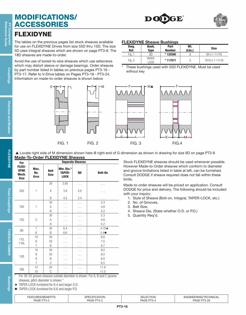
The tables on the previous pages list stock sheaves available for use on FLEXIDYNE Drives from size 55D thru 15D. The size 5D uses integral sheaves which are shown on page PT3-8. The 18D sheaves are made-to-order.
Avoid the use of bored-to-size sheaves which use setscrews which may distort sleeve or damage bearings. Order sheaves by part number listed in tables on previous pages PT3-16 - PT3-17. Refer to V-Drive tables on Pages PT3-18 - PT3-24. Information on made-to-order sheaves is shown below
FLEXIDYNE Sheave BushingsDwg.Ref.
Bush.Type
PartNumber
Wt.(Lbs.) Size
Fig. 1 QD * 120580 .6 SH x 1-11/16
Fig. 2TAPER- LOCK
* 117071 .5 1610 x 1-11/16
* These bushings used with 55D FLEXIDYNE. Must be used without key
▲ Locate right side of M dimension shown here @ right end of G dimension as shown in drawing for size 9D on page PT3-8Made-To-Order FLEXIDYNE Sheaves
ForFLEXI-DYNEMech.Size
Separate Sheaves Stock FLEXIDYNE sheaves should be used whenever possible. However Made-to-Order sheaves which conform to diameter and groove limitations listed in table at left, can be furnished. Consult DODGE if sheave required does not fall within these limits.
Made-to-order sheaves will be priced on application. Consult DODGE for price and delivery. The following should be included with your inquiry:
Max.No.
Grvs
BeltSize
Min. Dia.*TAPER-LOCK
QD Bolt-On
55D 1
3V 3.85 . . . . . .
A 3.8 3.0 . . .
B 4.2 3.4 . . . 1. Style of Sheave (Bolt-on, Integral, TAPER-LOCK, etc.)
70D 13V . . . . . . 5.3 2. No. of Grooves.A . . . . . . 4.8 3. Belt Size.B . . . . . . 5.2 4. Sheave Dia. (State whether O.D. or P.D.)
75D 23V . . . . . . 5.3 5. Quantity Req’d.A . . . . . . 4.8B . . . . . . 5.2
9D7 3V 6.4 . . . 4.75★
6 B 6.6 . . . 5.4◆
11D,11DL
10 3V . . . . . . 6.66 5V . . . . . . 7.57 B . . . . . . 6.7
15D
15 3V . . . . . . 8.09 5V . . . . . . 9.09 B . . . . . . 8.07 C . . . . . . 8.5
18D13 5V . . . . . . 11.810 C . . . . . . 11.0
* For 3V, 5V groove sheaves outside diameter is shown. For A, B and C groove sheaves, pitch diameter is shown.”★ TAPER-LOCK furnished for 6.4 and larger O.D.◆ TAPER-LOCK furnished for 6.6 and larger P.D.
FLEXIDYNE
L
E LF
FIG. 1 FIG. 2 FIG. 3 FIG.4
F M F M▲ F
E ME L

PT3-19
PT
Co
mp
on
en
t R
efe
ren
ce
Gu
ide
Co
up
ling
sC
lutc
hes
an
d B
rake
sF
LE
XID
YN
EF
luid
Co
up
ling
sT
OR
QU
E-T
AM
ER
Bu
shin
gs
MODIFICATIONS/ACCESSORIES
FEATURES/BENEFITS PAGE PT3-2
SPECIFICATION PAGE PT3-3
SELECTION PAGE PT3-4
ENGINEERING/TECHNICAL PAGE PT3-26
FLEXIDYNEDSThese are typical drives for average service conditions
Driven by 1750 RPM Motors Driven by 1750 RPM Motors
DrivenRPM
V-BeltDriveRatio
Sheave Quan.& BeltSize ◆
DrivenRPM
V-BeltDriveRatio
Sheave Quan.& BeltSize ◆
Driver▲
Driven*
Driver▲
Driven*
2250 1.29 3.6 AK30H 1-4L 1122 1.56 3.6 5.6 **2122 1.22 3.4 AK30H 1-4L 1117 1.57 3.0 AK51H 1-4L2100 1.20 3.6 AK32H 1-4L 1105 1.58 3.6 AK61H 1-4L1970 1.13 3.6 AK34H 1-4L 1048 1.67 3.0 AK54H 1-4L1970 1.13 3.4 AK32H 1-4L 1012 1.73 3.0 AK56H 1-4L1875 1.07 3.0 AK30H 1-4L 1008 1.74 3.4 BK65H 1-5L1850 1.06 3.6 3.4 ** 983 1.78 3.6 6.4 **1850 1.06 3.4 AK34H 1-4L 955 1.83 3.0 AK59H 1-4L1750 1.00 3.0 AK32H 1-4L 936 1.87 3.0 5.6 **1707 1.03 4.0 BK47H 1-5L 930 1.88 3.4 BK70H 1-5L1703 1.03 3.6 AK41H 1-4L 921 1.90 3.0 AK61H 1-4L1651 1.06 3.6 3.8 ** 900 1.94 3.6 AK74H 1-4L1651 1.06 3.4 BK40H 1-5L 875 2.00 3.0 AK64H 1-4L1640 1.07 3.0 AK34H 1-4L 833 2.10 4.0 BK90H 1-5L1577 1.11 3.6 AK44H 1-4L 804 2.18 3.4 BK80H 1-5L1572 1.11 4.0 BK50H 1-5L 788 2.22 3.6 AK84H 1-4L1615 1.08 3.6 BK45H 1-5L 768 2.28 3.6 8.2 **1544 1.13 3.0 3.4 ** 751 2.33 3.0 AK74H 1-4L1525 1.15 3.4 BK45H 1-5L 708 2.47 3.4 BK90H 1-5L1496 1.17 3.6 AK46H 1-4L 700 2.50 3.6 AK94H 1-4L1522 1.15 4.0 BK52H 1-5L 673 2.60 4.0 BK110H 1-5L1458 1.20 3.0 3.6 ** 656 2.67 3.0 AK84H 1-4L1451 1.21 3.4 BK47H 1-5L 641 2.73 3.0 8.2 **1429 1.23 4.0 BK55H 1-5L 630 2.78 3.6 AK104H 1-4L1400 1.25 3.6 AK49H 1-4L 614 2.85 4.0 BK120H 1-5L1423 1.23 3.0 AK41H 1-4L 595 2.94 3.6 10.6 **1378 1.27 3.0 3.8 ** 583 3.00 3.0 AK94H 1-4L1376 1.28 3.6 4.6 ** 572 3.06 3.4 BK110H 1-5L1372 1.28 4.0 BK57H 1-5L 525 3.33 3.0 AK104H 1-4L1316 1.33 3.6 4.8 ** 496 3.53 3.0 10.6 **1340 1.31 3.6 AK51H 1-4L 455 3.85 4.0 BK160H 1-5L1313 1.33 3.0 AK44H 1-4L 450 3.89 3.6 AK144H 1-4L1296 1.35 4.0 BK60H 1-5L 444 3.94 3.4 BK140H 1-5L1293 1.35 3.4 BK52H 1-5L 438 4.00 3.0 AK124H 1-4L1259 1.39 3.6 AK54H 1-4L 420 4.17 3.6 AK154H 1-4L1250 1.40 3.0 AK46H 1-4L 386 4.53 3.4 BK160H 1-5L1215 1.44 3.6 AK56H 1-4L 375 4.67 3.0 AK144H 1-4L1214 1.44 3.4 BK55H 1-5L 350 5.00 3.0 AK154H 1-4L1186 1.48 4.0 BK65H 1-5L 323 5.41 3.4 BK190H 1-5L1167 1.50 3.0 AK49H 1-4L 292 6.00 3.0 AK184H 1-4L1167 1.50 3.4 BK57H 1-5L1145 1.58 3.6 AK59H 1-4L
** Use one belt, either A or 4L. * All Sheaves are DODGE stock sheaves. Size numbers are shown for FHP 4L and 5L sheaves; datum diameters for Dual Duty sheaves.▲ Pitch diameter of integral sheaves supplied with stock 5D-FLEXIDYNE.
◆ “A” Belts may be used in place of 4L belts on 3.0 P.D. sheaves or larger. “AX” Belts may be used in place of 4L belts on 2.2 P.D. sheaves or larger. “B” Belts are not recommended in place of 5L belts. “BX” Belts may be used in place of 5L belts on 4.0 P.D. sheaves or larger.
PT3-20
MODIFICATIONS/ACCESSORIESP
T C
om
po
ne
nt
Re
fere
nc
e Gu
ide
Co
up
ling
sC
lutc
hes a
nd
Brakes
FL
EX
IDY
NE
Flu
id C
ou
plin
gs
TO
RQ
UE
-TAM
ER
Bu
shin
gs
FEATURES/BENEFITS PAGE PT3-2
SPECIFICATION PAGE PT3-3
SELECTION PAGE PT3-4
ENGINEERING/TECHNICAL PAGE PT3-26
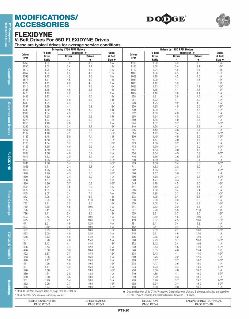
FLEXIDYNEV-Belt Drives For 55D FLEXIDYNE DrivesThese are typical drives for average service conditions
Driven by 1750 RPM Motors Driven by 1750 RPM Motors
DrivenRPM
V-BeltDriveRatio
Diameter ★ Quan.& BeltSize ◆
DrivenRPM
V-BeltDriveRatio
Diameter ★ Quan.& BeltSize ◆
Driver*
Driven♠
Driver*
Driven♠
1750 1.00 3.6 3.6 1-A 1160 1.00 3.0 3.0 1-A1750 1.00 3.4 3.4 1-3V 1160 1.00 3.4 3.4 1-3V1670 1.05 4.2 4.4 1-A 1112 1.04 4.6 4.8 1-B1657 1.06 4.5 4.8 1-3V 1098 1.06 4.5 4.8 1-3V1598 1.10 4.2 4.6 1-A 1059 1.10 4.2 4.6 1-A1573 1.11 4.5 5.0 1-3V 1061 1.09 4.1 4.5 1-3V1522 1.15 4.0 4.6 1-A 1036 1.12 5.0 5.6 1-B1515 1.15 4.1 4.8 1-3V 1026 1.13 3.7 4.1 1-3V1483 1.18 4.5 5.3 1-3V 1005 1.15 4.1 4.8 1-3V1470 1.19 4.2 5.0 1-A 1002 1.16 3.8 4.4 1-A1439 1.22 4.1 5.0 1-3V 958 1.21 3.8 4.6 1-A1411 1.24 5.0 6.2 1-B 954 1.22 4.1 5.0 1-3V1403 1.25 4.5 5.6 1-3V 928 1.25 3.2 4.0 1-A1357 1.29 4.1 5.3 1-3V 930 1.25 4.5 5.6 1-3V1342 1.30 4.6 6.0 1-B 899 1.29 4.1 5.3 1-3V1309 1.34 4.5 6.0 1-3V 892 1.30 4.0 5.2 1-A1298 1.35 4.6 6.2 1-B 868 1.34 4.5 6.0 1-3V1273 1.37 3.7 5.0 1-3V 859 1.35 4.0 5.4 1-A1250 1.40 4.0 5.6 1-A 844 1.37 3.7 5.0 1-3V1229 1.42 3.4 4.8 1-3V 840 1.38 4.2 5.8 1-A1207 1.45 4.0 5.8 1-A 816 1.42 3.8 5.4 1-A1197 1.46 4.1 6.0 1-3V 814 1.42 3.4 4.8 1-3V1182 1.48 5.0 7.4 1-B 800 1.45 4.5 6.5 1-3V1167 1.50 3.4 5.0 1-3V 791 1.47 3.0 4.4 1-A1135 1.54 3.7 5.6 1-3V 773 1.50 3.2 4.8 1-A1129 1.55 4.0 6.2 1-A 773 1.50 3.4 5.0 1-3V1100 1.59 3.4 5.3 1-3V 757 1.53 3.0 4.6 1-A1094 1.60 4.0 6.4 1-A 754 1.54 4.5 6.9 1-3V1073 1.63 3.8 6.2 1-A 746 1.56 3.6 5.6 1-A1059 1.65 3.7 6.0 1-3V 730 1.59 3.4 5.4 1-A1041 1.68 3.4 5.6 1-3V 729 1.59 3.4 5.3 1-3V1026 1.71 3.4 5.8 1-A 711 1.63 3.8 6.2 1-A1000 1.75 4.0 7.0 1-A 702 1.65 3.7 6.0 1-3V980 1.79 4.5 8.0 1-3V 696 1.67 3.0 5.0 1-A960 1.82 3.4 6.2 1-A 690 1.68 3.4 5.6 1-3V936 1.87 4.6 8.6 1-B 680 1.71 3.4 5.8 1-A920 1.90 3.7 6.9 1-3V 649 1.79 4.5 8.0 1-3V900 1.94 3.6 7.0 1-A 644 1.80 3.0 5.4 1-A895 1.95 3.4 6.5 1-3V 616 1.88 3.4 6.4 1-A850 2.06 3.4 7.0 1-A 610 1.90 3.7 6.9 1-3V843 2.08 3.4 6.9 1-3V 593 1.95 3.4 6.5 1-3V795 2.20 5.0 11.0 1-B 580 2.00 3.0 6.0 1-A792 2.21 3.7 8.0 1-3V 559 2.08 3.4 6.9 1-3V759 2.30 4.6 10.6 1-A 544 2.13 3.0 6.4 1-A726 2.41 3.4 8.2 1-A 527 2.20 5.0 11.0 1-B726 2.41 3.4 8.0 1-3V 525 2.21 3.7 8.0 1-3V693 2.52 4.2 10.6 1-A 503 2.30 4.6 10.6 1-A675 2.59 4.1 10.6 1-3V 489 2.37 4.5 10.6 1-3V671 2.61 4.6 12.0 1-A 481 2.41 3.4 8.2 1-A627 2.79 3.8 10.6 1-A 482 2.41 3.4 8.0 1-3V597 2.93 3.7 10.6 1-3V 448 2.59 4.1 10.6 1-3V583 3.00 4.0 12.0 1-A 445 2.61 4.6 12.0 1-A558 3.13 4.5 14.0 1-3V 406 2.86 4.2 12.0 1-A537 3.26 4.6 15.0 1-A 396 2.93 3.7 10.6 1-3V511 3.43 4.1 14.0 1-3V 372 3.12 3.4 10.6 1-A496 3.53 3.4 12.0 1-A 370 3.13 4.5 14.0 1-3V476 3.68 5.0 18.4 1-B 346 3.35 4.6 15.4 1-B452 3.87 3.7 14.0 1-3V 338 3.43 4.1 14.0 1-3V443 3.95 3.8 15.0 1-A 309 3.75 3.2 12.0 1-A420 4.17 3.6 15.0 1-A 299 3.87 3.7 14.0 1-3V411 4.26 4.5 19.0 1-3V 278 4.17 3.6 15.0 1-A397 4.41 3.4 15.0 1-A 274 4.23 3.4 14.0 1-3V376 4.66 4.1 19.0 1-3V 258 4.50 4.0 18.0 1-A369 4.74 3.8 18.0 1-A 249 4.66 4.1 19.0 1-3V350 5.00 3.6 18.0 1-A 219 5.29 3.4 18.0 1-A331 5.29 3.4 18.0 1-A 220 5.26 3.7 19.0 1-3V332 5.26 3.7 19.0 1-3V 202 5.74 3.4 19.0 1-3V305 5.74 3.4 19.0 1-3V 193 6.00 3.0 18.0 1-A
* Stock FLEXIDYNE sheaves listed on page PT3-16 - PT3-17. ★ Outside diameter of 3V DYNA-V sheaves. Datum diameter of A and B sheaves. All ratios are based on P.D. for DYNA-V Sheaves and Datum diameter for A and B Sheaves.* Stock TAPER-LOCK sheaves in V-drives section.

PT3-21
PT
Co
mp
on
en
t R
efe
ren
ce
Gu
ide
Co
up
ling
sC
lutc
hes
an
d B
rake
sF
LE
XID
YN
EF
luid
Co
up
ling
sT
OR
QU
E-T
AM
ER
Bu
shin
gs
MODIFICATIONS/ACCESSORIES
FEATURES/BENEFITS PAGE PT3-2
SPECIFICATION PAGE PT3-3
SELECTION PAGE PT3-4
ENGINEERING/TECHNICAL PAGE PT3-26
FLEXIDYNEV-Belts Drive For 70D FLEXIDYNE DrivesThese are typical drives for average service conditions
Driven by 1750 RPM MotorsDrivenRPM
V-BeltDriveRatio
Driven by 1750 RPM Motors
DrivenRPM
V-BeltDriveRatio
Diameter ★ Quan.& BeltSize ◆
Diameter ★ Quan.& BeltSize ◆
Driver*
Driven♠
Driver*
Driven♠
1750 1.00 5.6 5.6 1-B 1160 1.00 4.8 4.8 1-A1694 1.03 6.0 6.2 1-B 1123 1.03 6.0 6.2 1-B1690 1.04 5.6 5.8 1-B 1119 1.04 5.4 5.6 1-B1641 1.07 6.0 6.4 1-B 1094 1.06 5.0 5.3 1-3V1633 1.07 5.6 6.0 1-B 1083 1.07 5.6 6.0 1-B1632 1.07 5.6 6.0 1-3V 1082 1.07 5.6 6.0 1-3V1614 1.08 6.0 6.5 1-3V 1070 1.08 6.0 6.5 1-3V1591 1.10 6.0 6.6 1-B 1055 1.10 6.0 6.6 1-B1581 1.11 5.6 6.2 1-B 1040 1.12 5.2 5.8 1-B1575 1.11 5.4 6.0 1-B 1035 1.12 5.0 5.6 1-3V1544 1.13 6.0 6.8 1-B 1015 1.14 5.6 6.4 1-B1531 1.14 5.6 6.4 1-B 1008 1.15 6.0 6.9 1-3V1524 1.15 5.4 6.2 1-B 998 1.16 5.6 6.5 1-3V1520 1.15 6.0 6.9 1-3V 994 1.17 4.8 5.6 1-A1506 1.16 5.6 6.5 1-3V 967 1.20 5.0 6.0 1-A1485 1.18 5.6 6.6 1-B 965 1.20 5.0 6.0 1-3V1477 1.19 5.4 6.4 1-B 949 1.22 5.4 6.6 1-B1441 1.21 5.6 6.8 1-B 940 1.23 5.6 6.9 1-3V1432 1.22 5.4 6.6 1-B 928 1.25 4.8 6.0 1-A1419 1.23 6.0 7.4 1-B 914 1.27 5.2 6.6 1-B1418 1.23 5.6 6.9 1-3V 898 1.29 4.8 6.2 1-A1390 1.26 5.4 6.8 1-B 890 1.30 5.0 6.5 1-3V1324 1.32 5.6 7.4 1-B 878 1.32 5.6 7.4 1-B1310 1.34 6.0 8.0 1-3V 868 1.34 6.0 8.0 1-3V1265 1.38 5.0 6.9 1-3V 862 1.35 5.2 7.0 1-A1221 1.43 6.0 8.6 1-B 846 1.37 5.4 7.4 1-B1222 1.43 5.6 8.0 1-3V 838 1.38 5.0 6.9 1-3V1140 1.54 5.6 8.6 1-B 829 1.40 5.0 7.0 1-A1117 1.57 6.0 9.4 1-B 809 1.43 6.0 8.6 1-B1099 1.59 5.4 8.6 1-B 810 1.43 5.6 8.0 1-3V1090 1.61 5.0 8.0 1-3V 792 1.46 5.6 8.2 1-A1058 1.65 5.2 8.6 1-B 755 1.54 5.6 8.6 1-B1043 1.68 5.6 9.4 1-B 740 1.57 6.0 9.4 1-B1005 1.74 5.4 9.4 1-B 722 1.61 5.6 9.0 1-A987 1.77 6.0 10.6 1-3V 722 1.61 5.0 8.0 1-3V968 1.81 5.2 9.4 1-B 701 1.65 5.2 8.6 1-B955 1.83 6.0 11.0 1-B 679 1.71 4.8 8.2 1-A921 1.90 5.6 10.6 1-3V 666 1.74 5.4 9.4 1-B891 1.96 5.6 11.0 1-B 654 1.77 6.0 10.6 1-3V859 2.04 5.4 11.0 1-B 644 1.80 5.0 9.0 1-A847 2.07 6.0 12.4 1-B 613 1.89 5.6 10.6 1-A827 2.12 5.2 11.0 1-B 610 1.90 5.6 10.6 1-3V821 2.13 5.0 10.6 1-3V 591 1.96 5.6 11.0 1-B790 2.21 5.6 12.4 1-B 569 2.04 5.4 11.0 1-B762 2.30 5.4 12.4 1-B 548 2.12 5.2 11.0 1-B746 2.34 6.0 14.0 1-3V 544 2.13 5.0 10.6 1-3V734 2.38 5.2 12.4 1-B 525 2.21 4.8 10.6 1-A696 2.51 5.6 14.0 1-3V 505 2.30 5.4 12.4 1-B682 2.57 6.0 15.4 1-B 495 2.34 6.0 14.0 1-3V636 2.75 5.6 15.4 1-B 486 2.38 5.2 12.4 1-B621 2.82 5.0 14.0 1-3V 464 2.50 4.8 12.0 1-A614 2.85 5.4 15.4 1-B 462 2.51 5.6 14.0 1-3V609 2.87 6.4 18.4 1-B 452 2.57 6.0 15.4 1-B591 2.96 5.2 15.4 1-B 433 2.68 5.6 15.0 1-A571 3.07 6.0 18.4 1-B 422 2.75 5.6 15.4 1-B549 3.18 6.0 19.0 1-3V 412 2.82 5.0 14.0 1-3V533 3.29 5.6 18.4 1-B 402 2.88 5.2 15.0 1-A514 3.41 5.4 18.4 1-B 392 2.96 5.2 15.4 1-B513 3.41 5.6 19.0 1-3V 387 3.00 5.0 15.0 1-A495 3.54 5.2 18.4 1-B 371 3.12 4.8 15.0 1-A457 3.83 5.0 19.0 1-3V 364 3.18 6.0 19.0 1-3V. . . . . . . . . . . . . . . . . 361 3.21 5.6 18.0 1-A. . . . . . . . . . . . . . . . . 353 3.29 5.6 18.4 1-B. . . . . . . . . . . . . . . . . 340 3.41 5.6 19.0 1-3V. . . . . . . . . . . . . . . . . 335 3.46 5.2 18.0 1-A. . . . . . . . . . . . . . . . . 322 3.60 5.0 18.0 1-A. . . . . . . . . . . . . . . . . 309 3.75 4.8 18.0 1-A. . . . . . . . . . . . . . . . . 303 3.83 5.0 19.0 1-3V
* Stock FLEXIDYNE sheaves listed on page PT3-16 - PT3-17. ★ Outside diameter of 3V DYNA-V sheaves. Datum diameter of A and B sheaves. All ratios are based on P.D. for DYNA-V Sheaves and Datum diameter for A and B Sheaves.* Stock TAPER-LOCK sheaves in V-drives section.

PT3-22
MODIFICATIONS/ACCESSORIESP
T C
om
po
ne
nt
Re
fere
nc
e Gu
ide
Co
up
ling
sC
lutc
hes a
nd
Brakes
FL
EX
IDY
NE
Flu
id C
ou
plin
gs
TO
RQ
UE
-TAM
ER
Bu
shin
gs
FEATURES/BENEFITS PAGE PT3-2
SPECIFICATION PAGE PT3-3
SELECTION PAGE PT3-4
ENGINEERING/TECHNICAL PAGE PT3-26
FLEXIDYNEV-Belt Drives For 75D FLEXIDYNE DrivesThese are typical drives for average service conditions
Driven by 1750 RPM Motors Driven by 1750 RPM Motors
DrivenRPM
V-BeltDriveRatio
Diameter ★ Quan.& BeltSize ◆
DrivenRPM
V-BeltDriveRatio
Diameter ★ Quan.& BeltSize ◆
Driver*
Driven♠
Driver*
Driven♠
1750 1.00 5.6 5.6 2-B 1160 1.00 4.8 4.8 2-A1694 1.03 6.0 6.2 2-B 1114 1.04 4.8 5.0 2-A1690 1.04 5.6 5.8 2-B 1094 1.06 5.0 5.3 2-3V1641 1.07 6.0 6.4 2-B 1082 1.07 5.6 6.0 2-3V1632 1.07 5.6 6.0 2-3V 1071 1.08 4.8 5.2 2-A1614 1.08 6.0 6.5 2-3V 1072 1.08 6.0 6.5 2-3V1591 1.10 6.0 6.6 2-B 1055 1.10 6.0 6.6 2-B1544 1.13 6.0 6.8 2-B 1036 1.12 5.0 5.6 2-A1524 1.15 5.4 6.2 2-B 1035 1.12 5.0 5.6 2-3V1520 1.15 6.0 6.9 2-3V 1015 1.14 5.6 6.4 2-B1506 1.16 5.6 6.5 2-3V 1008 1.15 6.0 6.9 2-3V1485 1.18 5.6 6.6 2-B 1000 1.16 5.0 5.8 2-A1441 1.21 5.6 6.8 2-B 998 1.16 5.6 6.5 2-3V1419 1.23 6.0 7.4 2-B 994 1.17 4.8 5.6 2-A1418 1.23 5.6 6.9 2-3V 984 1.18 5.6 6.6 2-B1390 1.26 5.4 6.8 2-B 967 1.20 5.0 6.0 2-A1324 1.32 5.6 7.4 2-B 965 1.20 5.0 6.0 2-3V1310 1.34 6.0 8.0 2-3V 960 1.21 4.8 5.8 2-A1277 1.37 5.4 7.4 2-B 941 1.23 6.0 7.4 2-B1265 1.38 5.0 6.9 2-3V 940 1.23 5.6 6.9 2-3V1221 1.43 6.0 8.6 2-B 935 1.24 5.0 6.2 2-A1222 1.43 5.6 8.0 2-3V 928 1.25 4.8 6.0 2-A1140 1.54 5.6 8.6 2-B 906 1.28 5.0 6.4 2-A1117 1.57 6.0 9.4 2-B 898 1.29 4.8 6.2 2-A1099 1.59 5.4 8.6 2-B 890 1.30 5.0 6.5 2-3V1090 1.61 5.0 8.0 2-3V 887 1.31 5.2 6.8 2-B1043 1.68 5.6 9.4 2-B 870 1.33 4.8 6.4 2-A1005 1.74 5.4 9.4 2-B 868 1.34 6.0 8.0 2-3V987 1.77 6.0 10.6 2-3V 862 1.35 5.2 7.0 2-A968 1.81 5.2 9.4 2-B 846 1.37 5.4 7.4 2-B955 1.83 6.0 11.0 2-B 838 1.38 5.0 6.9 2-3V921 1.90 5.6 10.6 2-3V 829 1.40 5.0 7.0 2-A891 1.96 5.6 11.0 2-B 809 1.43 6.0 8.6 2-B859 2.04 5.4 11.0 2-B 810 1.43 5.6 8.0 2-3V847 2.07 6.0 12.4 2-B 795 1.46 4.8 7.0 2-A827 2.12 5.2 11.0 2-B 755 1.54 5.6 8.6 2-B821 2.13 5.0 10.6 2-3V 736 1.58 5.2 8.2 2-A790 2.21 5.6 12.4 2-B 722 1.61 5.0 8.0 2-3V762 2.30 5.4 12.4 2-B 707 1.64 5.0 8.2 2-A746 2.34 6.0 14.0 2-3V 679 1.71 4.8 8.2 2-A734 2.38 5.2 12.4 2-B 670 1.73 5.2 9.0 2-A696 2.51 5.6 14.0 2-3V 654 1.77 6.0 10.6 2-3V682 2.57 6.0 15.4 2-B 644 1.80 5.0 9.0 2-A636 2.75 5.6 15.4 2-B 619 1.87 4.8 9.0 2-A621 2.82 5.0 14.0 2-3V 610 1.90 5.6 10.6 2-3V614 2.85 5.4 15.4 2-B 591 1.96 5.6 11.0 2-B591 2.96 5.2 15.4 2-B 569 2.04 5.4 11.0 2-B571 3.07 6.0 18.4 2-B 547 2.12 5.0 10.6 2-A549 3.18 6.0 19.0 2-3V 544 2.13 5.0 10.6 2-3V525 3.33 6.0 20.0 2-B 525 2.21 4.8 10.6 2-A514 3.41 5.4 18.4 2-B 495 2.34 6.0 14.0 2-3V513 3.41 5.6 19.0 2-3V 486 2.38 5.2 12.4 2-B490 3.57 5.6 20.0 2-B 464 2.50 4.8 12.0 2-A455 3.85 5.2 20.0 2-B 462 2.51 5.6 14.0 2-3V457 3.83 5.0 19.0 2-3V 422 2.75 5.6 15.4 2-B420 4.17 6.0 25.0 2-B 412 2.82 5.0 14.0 2-3V417 4.19 6.0 25.0 2-3V 402 2.88 5.2 15.0 2-A392 4.46 5.6 25.0 2-B 387 3.00 5.0 15.0 2-A389 4.50 5.6 25.0 2-3V 371 3.12 4.8 15.0 2-A378 4.63 5.4 25.0 2-B 364 3.18 6.0 19.0 2-3V364 4.81 5.2 25.0 2-B 340 3.41 5.6 19.0 2-3V350 5.00 6.0 30.0 2-B 322 3.60 5.0 18.0 2-A347 5.04 5.0 25.0 2-3V 309 3.75 4.8 18.0 2-A327 5.36 5.6 30.0 2-B 303 3.83 5.0 19.0 2-3V303 5.77 5.2 30.0 2-B 278 4.17 6.0 25.0 2-B276 6.33 6.0 38.0 2-B 277 4.19 6.0 25.0 2-3V258 6.79 5.6 38.0 2-B 258 4.50 5.6 25.0 2-3V249 7.04 5.4 38.0 2-B 230 5.04 5.0 25.0 2-3V
* Stock FLEXIDYNE sheaves listed on page PT3-16 - PT3-17. ★ Outside diameter of 3V DYNA-V sheaves. Datum diameter of A and B sheaves. All ratios are based on P.D. for DYNA-V Sheaves and Datum diameter for A and B Sheaves.* Stock TAPER-LOCK sheaves in V-drives section.

PT3-23
PT
Co
mp
on
en
t R
efe
ren
ce
Gu
ide
Co
up
ling
sC
lutc
hes
an
d B
rake
sF
LE
XID
YN
EF
luid
Co
up
ling
sT
OR
QU
E-T
AM
ER
Bu
shin
gs
MODIFICATIONS/ACCESSORIES
FEATURES/BENEFITS PAGE PT3-2
SPECIFICATION PAGE PT3-3
SELECTION PAGE PT3-4
ENGINEERING/TECHNICAL PAGE PT3-26
FLEXIDYNEV-Belt Drives For 9D FLEXIDYNE DrivesThese are typical drives for average service conditions
Driven by 1750 RPM Motors Driven by 1750 RPM Motors
DrivenRPM
V-BeltDriveRatio
Diameter ★ Quan.& BeltSize ◆
DrivenRPM
V-BeltDriveRatio
Diameter ★ Quan.& BeltSize ◆
Driver*
Driven♠
Driver*
Driven♠
1750 1.00 4.75 4.75 4-3V 1160 1.00 4.75 4.75 4-3V1683 1.04 5.0 5.2 5-A 1115 1.04 5.0 5.2 5-A1667 1.05 4.75 5.0 4-3V 1105 1.05 4.75 5.0 4-3V1636 1.07 5.6 6.0 4-A 1084 1.07 5.6 6.0 4-A1620 1.08 5.2 5.6 5-A 1074 1.08 5.2 5.6 5-A1577 1.11 5.4 6.0 5-B 1045 1.11 5.4 6.0 5-B1563 1.12 4.75 5.3 4-3V 1036 1.12 4.75 5.3 4-3V1549 1.13 5.3 6.0 4-3V 1027 1.13 5.3 6.0 4-3V1535 1.14 5.6 6.4 4-A 1018 1.14 5.6 6.4 4-A1522 1.15 6.0 6.9 4-3V 1009 1.15 6.0 6.9 4-3V1496 1.17 6.0 7.0 4-A 991 1.17 6.0 7.0 4-A1483 1.18 4.75 5.6 4-3V 983 1.18 4.75 5.6 4-3V1458 1.20 5.0 6.0 5-A 967 1.20 5.0 6.0 5-A1423 1.23 5.3 6.5 4-3V 943 1.23 5.3 6.5 4-3V1400 1.25 5.6 7.0 4-A 928 1.25 5.6 7.0 4-A1378 1.27 4.75 6.0 4-3V 913 1.27 4.75 6.0 4-3V1367 1.28 5.0 6.4 5-A 906 1.28 5.0 6.4 5-A1346 1.30 5.3 6.9 4-3V 892 1.30 5.3 6.9 4-3V1326 1.32 5.6 7.4 5-B 879 1.32 5.6 7.4 5-B1306 1.34 6.0 8.0 4-3V 866 1.34 6.0 8.0 4-3V1296 1.35 5.2 7.0 5-A 859 1.35 5.2 7.0 5-A1277 1.37 4.75 6.5 4-3V 847 1.37 4.75 6.5 4-3V1250 1.40 5.0 7.0 5-A 829 1.40 5.0 7.0 5-A1224 1.43 6.0 8.6 4-B 811 1.43 6.0 8.6 4-B1199 1.46 4.75 6.9 4-3V 795 1.46 4.75 6.9 4-3V1159 1.51 5.3 8.0 4-3V 768 1.51 5.3 8.0 4-3V
1136 1.54 5.6 8.6 5-B 753 1.54 5.6 8.6 5-B
1108 1.58 5.2 8.2 5-A 734 1.58 5.2 8.2 5-A1087 1.61 5.6 9.0 4-A 720 1.61 5.6 9.0 4-A1067 1.64 5.0 8.2 5-A 707 1.64 5.0 8.2 5-A1036 1.69 4.75 8.0 4-3V 686 1.69 4.75 8.0 4-3V1012 1.73 5.2 9.0 5-A 671 1.73 5.2 9.0 5-A989 1.77 6.0 10.6 4-3V 655 1.77 6.0 10.6 4-3V972 1.80 5.0 9.0 5-A 644 1.80 5.0 9.0 5-A956 1.83 6.0 11.0 4-B 634 1.83 6.0 11.0 4-B926 1.89 5.6 10.6 4-A 614 1.89 5.6 10.6 4-A902 1.94 6.4 12.4 4-B 598 1.94 6.4 12.4 4-B871 2.01 5.3 10.6 4-3V 577 2.01 5.3 10.6 4-3V858 2.04 5.2 10.6 5-A 569 2.04 5.2 10.6 5-A818 2.14 5.6 12.0 4-A 542 2.14 5.6 12.0 4-A792 2.21 5.6 12.4 5-B 525 2.21 5.6 12.4 5-B781 2.24 4.75 10.6 4-3V 518 2.24 4.75 10.6 4-3V748 2.34 6.0 14.0 4-3V 496 2.34 6.0 14.0 4-3V729 2.40 5.0 12.0 5-A 483 2.40 5.0 12.0 5-A700 2.50 6.0 12.0 4-A 464 2.50 6.0 15.0 4-A681 2.57 6.0 15.4 4-B 451 2.57 6.0 15.4 4-B658 2.66 5.3 14.0 4-3V 436 2.66 5.3 14.0 4-3V636 2.75 5.6 15.4 5-B 422 2.75 5.6 15.4 5-B608 2.88 5.2 15.0 5-A 403 2.88 5.2 15.0 5-A589 2.97 4.75 14.0 4-3V 391 2.97 4.75 14.0 4-3A570 3.07 6.0 18.4 4-B 378 3.07 6.0 18.4 4-B545 3.21 5.6 18.0 4-A 361 3.21 5.6 18.0 4-A532 3.29 5.6 18.4 5-B 353 3.29 5.6 18.4 5-B506 3.46 5.2 18.0 5-A 335 3.46 5.2 18.0 5-A485 3.61 5.3 19.0 4-3V 321 3.61 5.3 19.0 4-3V473 3.70 5.4 20.0 5-B 314 3.70 5.4 20.0 5-B448 3.91 6.4 25.0 4-B 297 3.91 6.4 25.0 4-B434 4.03 4.75 19.0 4-3V 288 4.03 4.75 19.0 4-3V420 4.17 6.0 25.0 4-B 278 4.17 6.0 25.0 4-B392 4.46 5.6 25.0 5-B 260 4.46 5.6 25.0 5-B368 4.75 5.3 25.0 4-3V 244 4.75 5.3 25.0 4-3V350 5.00 6.0 30.0 4-B 232 5.00 6.0 30.0 4-B330 5.31 4.75 25.0 4-3V 218 5.31 4.75 25.0 4-3V311 5.62 6.0 33.5 4-3V 206 5.62 6.0 33.5 4-3V295 5.94 6.4 38.0 4-B 195 5.94 6.4 38.0 4-B275 6.37 5.3 33.5 4-3V 182 6.37 5.3 33.5 4-3V258 6.79 5.6 38.0 5-B 171 6.79 5.6 38.0 5-B246 7.12 4.75 33.5 4-3V 163 7.12 4.75 33.5 4-3V
* Stock FLEXIDYNE sheaves listed on page PT3-16 - PT3-17. ★ Outside diameter of 3V DYNA-V sheaves. Datum diameter of A and B sheaves. All ratios are based on P.D. for DYNA-V Sheaves and Datum diameter for A and B Sheaves.* Stock TAPER-LOCK sheaves in V-drives section.

PT3-24
MODIFICATIONS/ACCESSORIESP
T C
om
po
ne
nt
Re
fere
nc
e Gu
ide
Co
up
ling
sC
lutc
hes a
nd
Brakes
FL
EX
IDY
NE
Flu
id C
ou
plin
gs
TO
RQ
UE
-TAM
ER
Bu
shin
gs
FEATURES/BENEFITS PAGE PT3-2
SPECIFICATION PAGE PT3-3
SELECTION PAGE PT3-4
ENGINEERING/TECHNICAL PAGE PT3-26
FLEXIDYNEV-Belt Drives For 11D, 11DL FLEXIDYNE DrivesThese are typical drives for average service conditions
Driven by 1750 RPM Motors Driven by 1750 RPM Motors
DrivenRPM
V-BeltDriveRatio
Diameter ★ Quan.& BeltSize ◆
DrivenRPM
V-BeltDriveRatio
Diameter ★ Quan.& BeltSize ◆
Driver*
Driven♠
Driver*
Driven♠
1750 1.00 6.5 6.5 5-3V 1160 1.00 6.5 6.5 5-3V1750 1.00 6.8 6.8 5-B 1160 1.00 6.8 6.8 5-B1699 1.03 6.6 6.8 5-B 1126 1.03 6.6 6.8 5-B1651 1.06 6.5 6.9 5-3V 1094 1.06 6.5 6.9 5-3V1636 1.07 7.5 8.0 3-5V 1084 1.07 7.5 8.0 3-5V1606 1.09 6.8 7.4 5-B 1064 1.09 6.8 7.4 5-B1563 1.12 6.6 7.4 5-B 1036 1.12 6.6 7.4 5-B1535 1.14 7.5 8.5 3-5V 1022 1.14 7.5 8.5 3-5V1509 1.16 7.4 8.6 5-B 1000 1.16 7.4 8.6 5-B1509 1.16 6.9 8.0 5-3V 1000 1.16 6.9 8.0 5-3V1458 1.20 7.5 9.0 3-5V 967 1.20 7.5 9.0 3-5V1423 1.23 6.5 8.0 5-3V 943 1.23 6.5 8.0 5-3V1411 1.24 7.5 9.25 3-5V 935 1.24 7.5 9.25 3-5V1389 1.26 6.8 8.6 5-B 921 1.26 6.8 8.6 5-B1378 1.27 7.4 9.4 5-B 913 1.27 7.4 9.4 5-B1367 1.28 8.6 11.0 5-B 906 1.28 8.6 11.0 5-B1346 1.30 7.5 9.75 3-5V 892 1.30 7.5 9.75 3-5V1346 1.30 6.6 8.6 5-B 892 1.30 6.6 8.6 5-B1268 1.38 7.5 10.3 3-5V 841 1.38 7.5 10.3 3-5V1268 1.38 6.8 9.4 5-B 841 1.38 6.8 9.4 5-B1232 1.42 6.6 9.4 5-B 817 1.42 6.6 9.4 5-B1215 1.44 8.6 12.4 5-B 806 1.44 8.6 12.4 5-B1199 1.46 7.5 10.9 3-5V 795 1.46 7.5 10.9 3-5V1174 1.49 7.4 11.0 5-B 779 1.49 7.4 11.0 5-B1136 1.54 6.9 10.6 5-3V 753 1.54 6.9 10.6 5-3V1108 1.58 7.5 11.8 3-5V 734 1.58 7.5 11.8 3-5V1080 1.62 6.8 11.0 5-B 716 1.62 6.8 11.0 5-B1067 1.64 6.5 10.6 5-3V 707 1.64 6.5 10.6 5-3V1048 1.67 6.6 11.0 5-B 695 1.67 6.6 11.0 5-B1042 1.68 7.5 12.5 3-5V 690 1.68 7.5 12.5 3-5V1042 1.68 7.4 12.4 5-B 690 1.68 7.4 12.4 5-B989 1.77 7.5 13.2 3-5V 655 1.77 7.5 13.2 3-5V978 1.79 8.6 15.4 5-B 648 1.79 8.6 15.4 5-B962 1.82 6.8 12.4 5-B 637 1.82 6.8 12.4 5-B931 1.88 7.5 14.0 3-5V 617 1.88 7.5 14.0 3-5V931 1.88 6.6 12.4 5-B 617 1.88 6.6 12.4 5-B871 2.01 7.5 15.0 3-5V 577 2.01 7.5 15.0 3-5V858 2.04 6.9 14.0 5-3V 569 2.04 6.9 14.0 5-3V841 2.08 7.4 15.4 5-B 558 2.08 7.4 15.4 5-B818 2.14 8.6 18.4 5-B 542 2.14 8.6 18.4 5-B814 2.15 7.5 16.0 3-5V 540 2.15 7.5 16.0 3-5V810 2.16 6.5 14.0 5-3V 537 2.16 6.5 14.0 5-3V774 2.26 6.8 15.4 5-B 513 2.26 6.8 15.4 5-B751 2.33 6.6 15.4 5-B 498 2.33 6.6 15.4 5-B703 2.49 7.4 18.4 5-B 466 2.49 7.4 18.4 5-B646 2.71 6.8 18.4 5-B 428 2.71 6.8 18.4 5-B632 2.77 6.9 19.0 5-3V 419 2.77 6.9 19.0 5-3V627 2.79 6.6 18.4 5-B 416 2.79 6.6 18.4 5-B614 2.85 7.5 21.2 3-5V 407 2.85 7.5 21.2 3-5V601 2.91 8.6 25.0 5-B 399 2.91 8.6 25.0 5-B595 2.94 6.5 19.0 5-3V 395 2.94 6.5 19.0 5-3V578 3.03 6.6 20.0 5-B 383 3.03 6.6 20.0 5-B518 3.38 7.4 25.0 5-B 343 3.38 7.4 25.0 5-B501 3.49 8.6 30.0 5-B 332 3.49 8.6 30.0 5-B481 3.64 6.9 25.0 5-3V 319 3.64 6.9 25.0 5-3V476 3.68 6.8 25.0 5-B 315 3.68 6.8 25.0 5-B464 3.77 7.5 28.0 3-5V 308 3.77 7.5 28.0 3-5V462 3.79 6.6 25.0 5-B 306 3.79 6.6 25.0 5-B452 3.87 6.5 25.0 5-3V 300 3.87 6.5 25.0 5-3V432 4.05 7.4 30.0 5-B 286 4.05 7.4 30.0 5-B397 4.41 6.8 30.0 5-B 263 4.41 6.8 30.0 5-B385 4.55 6.6 30.0 5-B 255 4.55 6.6 30.0 5-B359 4.88 6.9 33.5 5-3V 238 4.88 6.9 35.5 5-3V347 5.05 7.5 37.5 3-5V 230 5.05 7.5 37.5 3-5V340 5.14 7.4 38.0 5-B 226 5.14 7.4 38.0 5-B337 5.19 6.5 33.5 5-3V 224 5.19 6.5 33.5 5-3V313 5.59 6.8 38.0 5-B 208 5.59 6.8 38.0 5-B304 5.76 6.6 38.0 5-B 201 5.76 6.6 38.0 5-B
* Stock FLEXIDYNE sheaves listed on page PT3-16 - PT3-17. ★ Outside diameter of 3V DYNA-V sheaves. Datum diameter of A and B sheaves. All ratios are based on P.D. for DYNA-V Sheaves and Datum diameter for A and B Sheaves.* Stock TAPER-LOCK sheaves in V-drives section.

PT3-25
PT
Co
mp
on
en
t R
efe
ren
ce
Gu
ide
Co
up
ling
sC
lutc
hes
an
d B
rake
sF
LE
XID
YN
EF
luid
Co
up
ling
sT
OR
QU
E-T
AM
ER
Bu
shin
gs
MODIFICATIONS/ACCESSORIES
FEATURES/BENEFITS PAGE PT3-2
SPECIFICATION PAGE PT3-3
SELECTION PAGE PT3-4
ENGINEERING/TECHNICAL PAGE PT3-26
FLEXIDYNEV-Belt Drives For 15D FLEXIDYNE DrivesThese are typical drives for average service conditions
Driven by 1750 RPM Motors Driven by 1750 RPM Motors
DrivenRPM
V-BeltDriveRatio
Diameter ★ Quan.& BeltSize ◆
DrivenRPM
V-BeltDriveRatio
Diameter ★ Quan.& BeltSize ◆
Driver*
Driven♠
Driver*
Driven♠
1750 1.00 9.75 9.75 4-5V 1160 1.00 9.75 9.75 4-5V1699 1.03 9.0 9.25 5-5V 1126 1.03 9.0 9.25 5-5V1663 1.05 9.5 10.0 6-C 1102 1.05 9.5 10.0 6-C1651 1.06 9.75 10.3 4-5V 1094 1.06 9.75 10.3 4-5V1620 1.08 9.0 9.75 5-5V 1074 1.08 9.0 9.75 5-5V1606 1.09 8.5 9.25 5-5V 1064 1.09 8.5 9.25 5-5V1591 1.10 10.0 11.0 6-C 1055 1.10 10.0 11.0 6-C1575 1.11 9.0 10.0 6-C 1044 1.11 9.0 10.0 6-C1563 1.12 9.75 10.9 4-5V 1036 1.12 9.75 10.9 4-5V1531 1.14 10.5 12.0 5-C 1015 1.14 10.5 12.0 5-C1522 1.15 8.5 9.75 5-5V 1009 1.15 8.5 9.75 5-5V1496 1.17 9.0 10.5 6-C 994 1.17 9.0 10.5 6-C1458 1.20 10.0 12.0 6-C 966 1.20 10.0 12.0 6-C1446 1.21 9.75 11.8 4-5V 959 1.21 9.75 11.8 4-5V1432 1.22 9.0 11.0 6-C 949 1.22 9.0 11.0 6-C1413 1.24 10.5 13.0 5-C 937 1.24 10.5 13.0 5-C1385 1.26 9.5 12.0 6-C 918 1.26 9.5 12.0 6-C1367 1.28 9.75 12.5 4-3V 906 1.28 9.75 12.5 4-3V1357 1.29 8.5 10.9 5-5V 899 1.29 8.5 10.9 5-5V1346 1.30 10.0 13.0 6-C 892 1.30 10.0 13.0 6-C1336 1.31 9.0 11.8 5-5V 885 1.31 9.0 11.8 5-5V1313 1.33 10.5 14.0 5-C 870 1.33 10.5 14.0 5-C1287 1.36 9.75 13.2 4-5V 853 1.36 9.75 13.2 4-5V1279 1.37 9.5 13.0 6-C 848 1.37 9.5 13.0 6-C1259 1.39 8.5 11.8 5-5V 835 1.39 8.5 11.8 5-5V1250 1.40 10.0 14.0 6-C 829 1.40 10.0 14.0 6-C1215 1.44 9.75 14.0 4-5V 806 1.44 9.75 14.0 4-5V1190 1.47 9.0 13.2 5-5V 789 1.47 9.0 13.2 5-5V1182 1.48 8.5 12.5 5-5V 784 1.48 8.5 12.5 5-5V1148 1.52 10.5 16.0 5-C 761 1.52 10.5 16.0 5-C1136 1.54 9.75 15.0 4-5V 753 1.54 9.75 15.0 4-5V1122 1.56 8.5 13.2 5-5V 744 1.56 8.5 13.2 5-5V1094 1.60 10.0 16.0 6-C 725 1.60 10.0 16.0 6-C1061 1.65 9.75 16.0 4-5V 703 1.65 9.75 16.0 4-5V1048 1.67 9.0 15.0 5-5V 695 1.67 9.0 15.0 5-5V1039 1.68 9.5 16.0 6-C 689 1.68 9.5 16.0 6-C989 1.77 8.5 15.0 5-5V 655 1.77 8.5 15.0 5-5V978 1.79 9.0 16.0 5-5V 648 1.79 9.0 16.0 5-5V926 1.89 8.5 16.0 5-5V 614 1.89 8.5 16.0 5-5V919 1.91 10.5 20.0 5-C 609 1.91 10.5 20.0 5-C875 2.00 10.0 20.0 6-C 580 2.00 10.0 20.0 6-C831 2.10 9.5 20.0 6-C 551 2.10 9.5 20.0 6-C799 2.19 9.75 21.2 4-5V 530 2.19 9.75 21.2 4-5V788 2.22 9.0 20.0 6-C 522 2.22 9.0 20.0 6-C766 2.28 10.5 24.0 5-C 508 2.28 10.5 24.0 5-C738 2.37 9.0 21.2 5-5V 489 2.37 9.0 21.2 5-5V729 2.40 10.0 24.0 6-C 483 2.40 10.0 24.0 6-C697 2.51 8.5 21.2 5-5V 462 2.51 8.5 21.2 5-5V656 2.67 9.0 24.0 6-C 435 2.67 9.0 24.0 6-C612 2.86 10.5 30.0 5-C 406 2.86 10.5 30.0 5-C606 2.89 9.75 28.0 4-5V 401 2.89 9.75 28.0 4-5V583 3.00 10.0 30.0 6-C 386 3.00 10.0 30.0 6-C559 3.13 9.0 28.0 5-5V 371 3.13 9.0 28.0 5-5V527 3.32 8.5 28.0 5-5V 349 3.32 8.5 28.0 5-5V510 3.43 10.5 36.0 5-C 338 3.43 10.5 36.0 5-C486 3.60 10.0 36.0 6-C 322 3.60 10.0 36.0 6-C462 3.79 9.5 36.0 6-C 306 3.79 9.5 36.0 6-C451 3.88 9.75 37.5 4-5V 299 3.88 9.75 37.5 4-5V438 4.00 9.0 36.0 6-C 290 4.00 9.0 36.0 6-C417 4.20 9.0 37.5 5-5V 276 4.20 9.0 37.5 5-5V393 4.45 8.5 37.5 5-5V 261 4.45 8.5 37.5 5-5V378 4.64 9.5 44.0 6-C 251 4.64 9.5 44.0 6-C368 4.76 10.5 50.0 5-C 244 4.76 10.5 50.0 5-C358 4.89 9.0 44.0 6-C 237 4.89 9.0 44.0 6-C350 5.00 10.0 50.0 6-C 232 5.00 10.0 50.0 6-C338 5.17 9.75 50.0 4-5V 224 5.17 9.75 50.0 4-5V312 5.61 9.0 50.0 5-5V 207 5.61 9.0 50.0 5-5V295 5.94 8.5 50.0 5-5V 195 5.94 8.5 50.0 5-5V
* Stock FLEXIDYNE sheaves listed on page PT3-16 - PT3-17. ★ Outside diameter of 3V DYNA-V sheaves. Datum diameter of A and B sheaves. All ratios are based on P.D. for DYNA-V Sheaves and Datum diameter for A and B Sheaves.* Stock TAPER-LOCK sheaves in V-drives section.
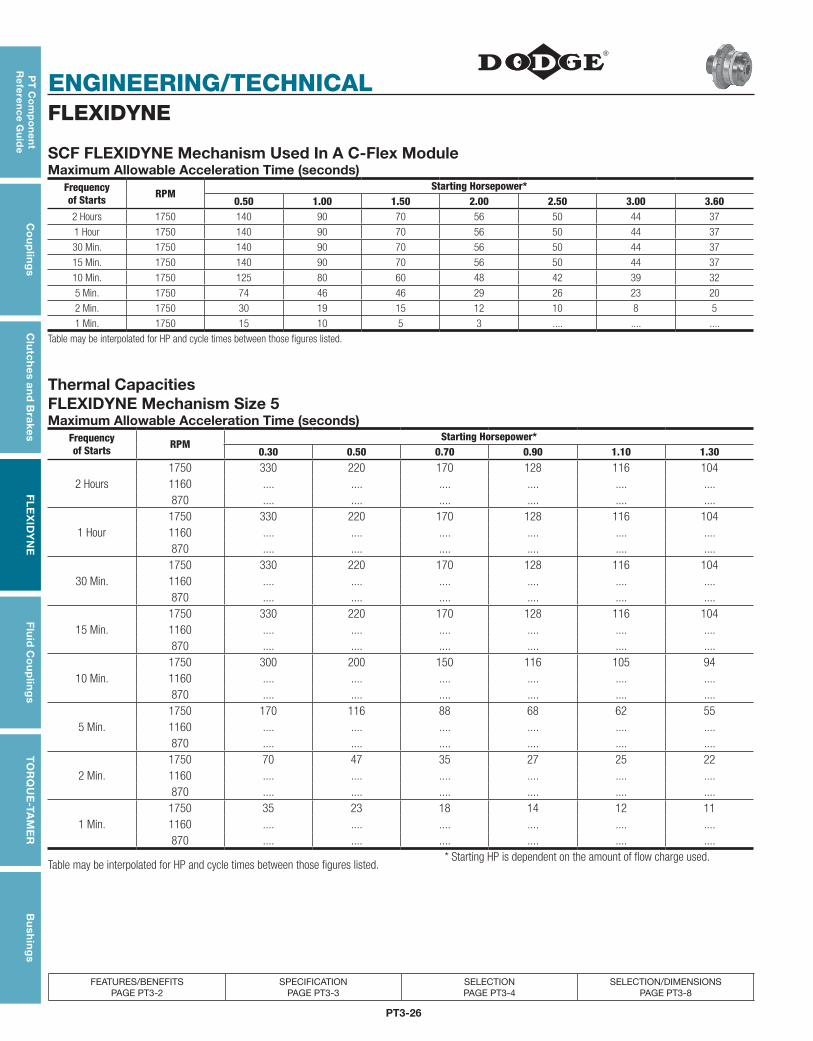
PT3-26
ENGINEERING/TECHNICAL
PT
Co
mp
on
en
t R
efe
ren
ce G
uid
eC
ou
plin
gs
Clu
tch
es an
d B
rakesF
LE
XID
YN
EF
luid
Co
up
ling
sT
OR
QU
E-TA
ME
RB
ush
ing
s
FEATURES/BENEFITS PAGE PT3-2
SPECIFICATION PAGE PT3-3
SELECTION PAGE PT3-4
SELECTION/DIMENSIONS PAGE PT3-8
FLEXIDYNE
SCF FLEXIDYNE Mechanism Used In A C-Flex ModuleMaximum Allowable Acceleration Time (seconds)
Frequencyof Starts RPM
Starting Horsepower*0.50 1.00 1.50 2.00 2.50 3.00 3.60
2 Hours 1750 140 90 70 56 50 44 37
1 Hour 1750 140 90 70 56 50 44 37
30 Min. 1750 140 90 70 56 50 44 37
15 Min. 1750 140 90 70 56 50 44 37
10 Min. 1750 125 80 60 48 42 39 32
5 Min. 1750 74 46 46 29 26 23 20
2 Min. 1750 30 19 15 12 10 8 5
1 Min. 1750 15 10 5 3 .... .... ....
Table may be interpolated for HP and cycle times between those figures listed.
Thermal Capacities FLEXIDYNE Mechanism Size 5Maximum Allowable Acceleration Time (seconds)
Frequencyof Starts RPM
Starting Horsepower*0.30 0.50 0.70 0.90 1.10 1.30
1750 330 220 170 128 116 1042 Hours 1160 .... .... .... .... .... ....
870 .... .... .... .... .... ....1750 330 220 170 128 116 104
1 Hour 1160 .... .... .... .... .... ....870 .... .... .... .... .... ....1750 330 220 170 128 116 104
30 Min. 1160 .... .... .... .... .... ....870 .... .... .... .... .... ....1750 330 220 170 128 116 104
15 Min. 1160 .... .... .... .... .... ....870 .... .... .... .... .... ....1750 300 200 150 116 105 94
10 Min. 1160 .... .... .... .... .... ....870 .... .... .... .... .... ....1750 170 116 88 68 62 55
5 Min. 1160 .... .... .... .... .... ....870 .... .... .... .... .... ....1750 70 47 35 27 25 22
2 Min. 1160 .... .... .... .... .... ....870 .... .... .... .... .... ....1750 35 23 18 14 12 11
1 Min. 1160 .... .... .... .... .... ....870 .... .... .... .... .... ....
Table may be interpolated for HP and cycle times between those figures listed.* Starting HP is dependent on the amount of flow charge used.

PT3-27
PT
Co
mp
on
en
t R
efe
ren
ce
Gu
ide
Co
up
ling
sC
lutc
hes
an
d B
rake
sF
LE
XID
YN
EF
luid
Co
up
ling
sT
OR
QU
E-T
AM
ER
Bu
shin
gs
ENGINEERING/TECHNICAL
FEATURES/BENEFITS PAGE PT3-2
SPECIFICATION PAGE PT3-3
SELECTION PAGE PT3-4
SELECTION/DIMENSIONS PAGE PT3-8
FLEXIDYNE
FLEXIDYNE Mechanism Size 55Maximum Allowable Acceleration Time (seconds)
Frequency of Starts RPM
Starting Horsepower*0.50 0.75 1.00 1.50 2.00 2.50 3.00 3.50 4.00
1750 .... .... 125 92 76 67 60 55 502 Hours 1160 250 175 148 110 .... .... .... .... ....
870 .... .... .... .... .... .... .... .... ....1750 .... .... 125 92 76 67 60 55 50
1 Hour 1160 250 175 148 110 .... .... .... .... ....870 .... .... .... .... .... .... .... .... ....
1750 .... .... 125 92 76 67 60 55 5030 Min. 1160 250 175 148 110 .... .... .... .... ....
870 .... .... .... .... .... .... .... .... ....1750 .... .... 125 92 76 67 60 55 50
15 Min. 1160 250 175 148 110 .... .... .... .... ....870 .... .... .... .... .... .... .... .... ....
1750 .... .... 96 67 60 52 47 43 4010 Min. 1160 190 130 110 82 .... .... .... .... ....
870 .... .... .... .... .... .... .... .... ....1750 .... .... 58 41 37 32 29 25 20
5 Min. 1160 110 80 68 50 .... .... .... .... ....870 .... .... .... .... .... .... .... .... ....
1750 .... .... 30 23 20 17 15 13 102 Min. 1160 60 40 35 28 .... .... .... .... ....
870 .... .... .... .... .... .... .... .... ....1750 .... .... 19 15 13 11 9 8 6
1 Min. 1160 33 26 22 18 .... .... .... .... ....870 .... .... .... .... .... .... .... .... ....
FLEXIDYNE Mechanism Size 70Maximum Allowable Acceleration Time (seconds)
Frequency of Starts RPM
Starting Horsepower*0.50 0.75 1.00 2.00 2.50 3.00 4.00 6.00 8.00 10.00
1750 .... .... .... 210 180 150 110 80 63 532 Hours 1160 .... .... 500 260 190 170 130 .... .... ....
870 900 800 550 .... .... .... .... .... .... ....1750 .... .... .... 210 180 150 110 80 63 53
1 Hour 1160 .... .... 500 260 190 170 130 .... .... ....870 900 800 550 .... .... .... .... .... .... ....
1750 .... .... .... 210 180 150 110 80 63 5330 Min. 1160 .... .... 500 260 190 170 130 .... .... ....
870 900 800 550 .... .... .... .... .... .... ....1750 .... .... .... 190 160 140 100 72 56 46
15 Min. 1160 .... .... 450 230 165 155 118 .... .... ....870 800 700 500 .... .... .... .... .... .... ....
1750 .... .... .... 170 140 120 83 60 41 3610 Min. 1160 .... .... 320 190 143 133 90 .... .... ....
870 500 400 330 .... .... .... .... .... .... ....1750 .... .... .... 105 85 74 54 38 29 23
5 Min. 1160 .... .... 200 120 88 80 60 .... .... ....870 250 230 210 .... .... .... .... .... .... ....
1750 .... .... .... 58 45 39 30 21 16 132 Min. 1160 .... .... 80 60 49 45 36 .... .... ....
870 100 100 100 .... .... .... .... .... .... ....1750 .... .... .... 36 29 25 19 13 10 8
1 Min. 1160 .... .... 45 38 33 28 23 .... .... ....870 50 50 50 .... .... .... .... .... .... ....
Table may be interpolated for HP and cycle times between those figures listed.
* Starting HP is dependent on the amount of flow charge used
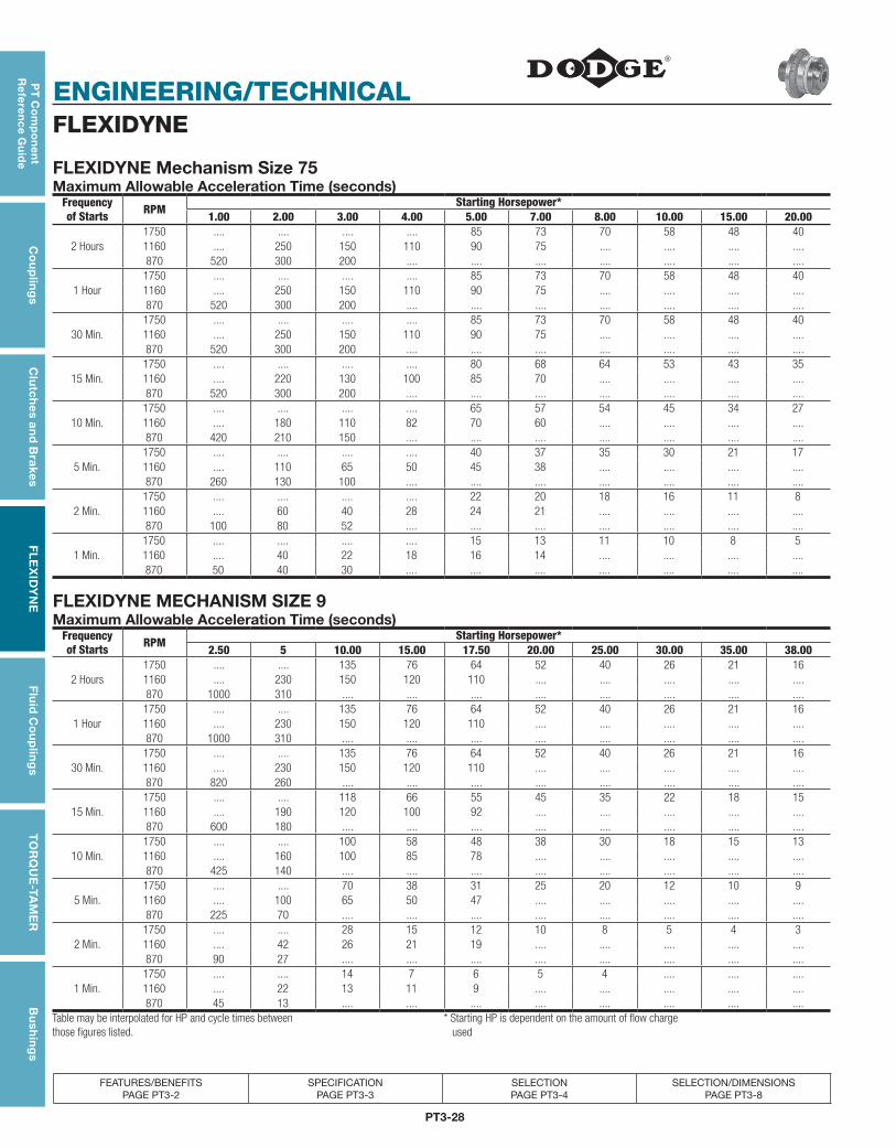
PT3-28
ENGINEERING/TECHNICAL
PT
Co
mp
on
en
t R
efe
ren
ce G
uid
eC
ou
plin
gs
Clu
tch
es an
d B
rakesF
LE
XID
YN
EF
luid
Co
up
ling
sT
OR
QU
E-TA
ME
RB
ush
ing
s
FEATURES/BENEFITS PAGE PT3-2
SPECIFICATION PAGE PT3-3
SELECTION PAGE PT3-4
SELECTION/DIMENSIONS PAGE PT3-8
FLEXIDYNE
FLEXIDYNE Mechanism Size 75Maximum Allowable Acceleration Time (seconds)
Frequency of Starts RPM
Starting Horsepower*1.00 2.00 3.00 4.00 5.00 7.00 8.00 10.00 15.00 20.00
1750 .... .... .... .... 85 73 70 58 48 402 Hours 1160 .... 250 150 110 90 75 .... .... .... ....
870 520 300 200 .... .... .... .... .... .... ....1750 .... .... .... .... 85 73 70 58 48 40
1 Hour 1160 .... 250 150 110 90 75 .... .... .... ....870 520 300 200 .... .... .... .... .... .... ....
1750 .... .... .... .... 85 73 70 58 48 4030 Min. 1160 .... 250 150 110 90 75 .... .... .... ....
870 520 300 200 .... .... .... .... .... .... ....1750 .... .... .... .... 80 68 64 53 43 35
15 Min. 1160 .... 220 130 100 85 70 .... .... .... ....870 520 300 200 .... .... .... .... .... .... ....
1750 .... .... .... .... 65 57 54 45 34 2710 Min. 1160 .... 180 110 82 70 60 .... .... .... ....
870 420 210 150 .... .... .... .... .... .... ....1750 .... .... .... .... 40 37 35 30 21 17
5 Min. 1160 .... 110 65 50 45 38 .... .... .... ....870 260 130 100 .... .... .... .... .... .... ....
1750 .... .... .... .... 22 20 18 16 11 82 Min. 1160 .... 60 40 28 24 21 .... .... .... ....
870 100 80 52 .... .... .... .... .... .... ....1750 .... .... .... .... 15 13 11 10 8 5
1 Min. 1160 .... 40 22 18 16 14 .... .... .... ....870 50 40 30 .... .... .... .... .... .... ....
FLEXIDYNE MECHANISM SIZE 9Maximum Allowable Acceleration Time (seconds)
Frequency of Starts RPM
Starting Horsepower*2.50 5 10.00 15.00 17.50 20.00 25.00 30.00 35.00 38.00
1750 .... .... 135 76 64 52 40 26 21 162 Hours 1160 .... 230 150 120 110 .... .... .... .... ....
870 1000 310 .... .... .... .... .... .... .... ....1750 .... .... 135 76 64 52 40 26 21 16
1 Hour 1160 .... 230 150 120 110 .... .... .... .... ....870 1000 310 .... .... .... .... .... .... .... ....
1750 .... .... 135 76 64 52 40 26 21 1630 Min. 1160 .... 230 150 120 110 .... .... .... .... ....
870 820 260 .... .... .... .... .... .... .... ....1750 .... .... 118 66 55 45 35 22 18 15
15 Min. 1160 .... 190 120 100 92 .... .... .... .... ....870 600 180 .... .... .... .... .... .... .... ....
1750 .... .... 100 58 48 38 30 18 15 1310 Min. 1160 .... 160 100 85 78 .... .... .... .... ....
870 425 140 .... .... .... .... .... .... .... ....1750 .... .... 70 38 31 25 20 12 10 9
5 Min. 1160 .... 100 65 50 47 .... .... .... .... ....870 225 70 .... .... .... .... .... .... .... ....
1750 .... .... 28 15 12 10 8 5 4 32 Min. 1160 .... 42 26 21 19 .... .... .... .... ....
870 90 27 .... .... .... .... .... .... .... ....1750 .... .... 14 7 6 5 4 .... .... ....
1 Min. 1160 .... 22 13 11 9 .... .... .... .... ....870 45 13 .... .... .... .... .... .... .... ....
Table may be interpolated for HP and cycle times between those figures listed.
* Starting HP is dependent on the amount of flow charge used
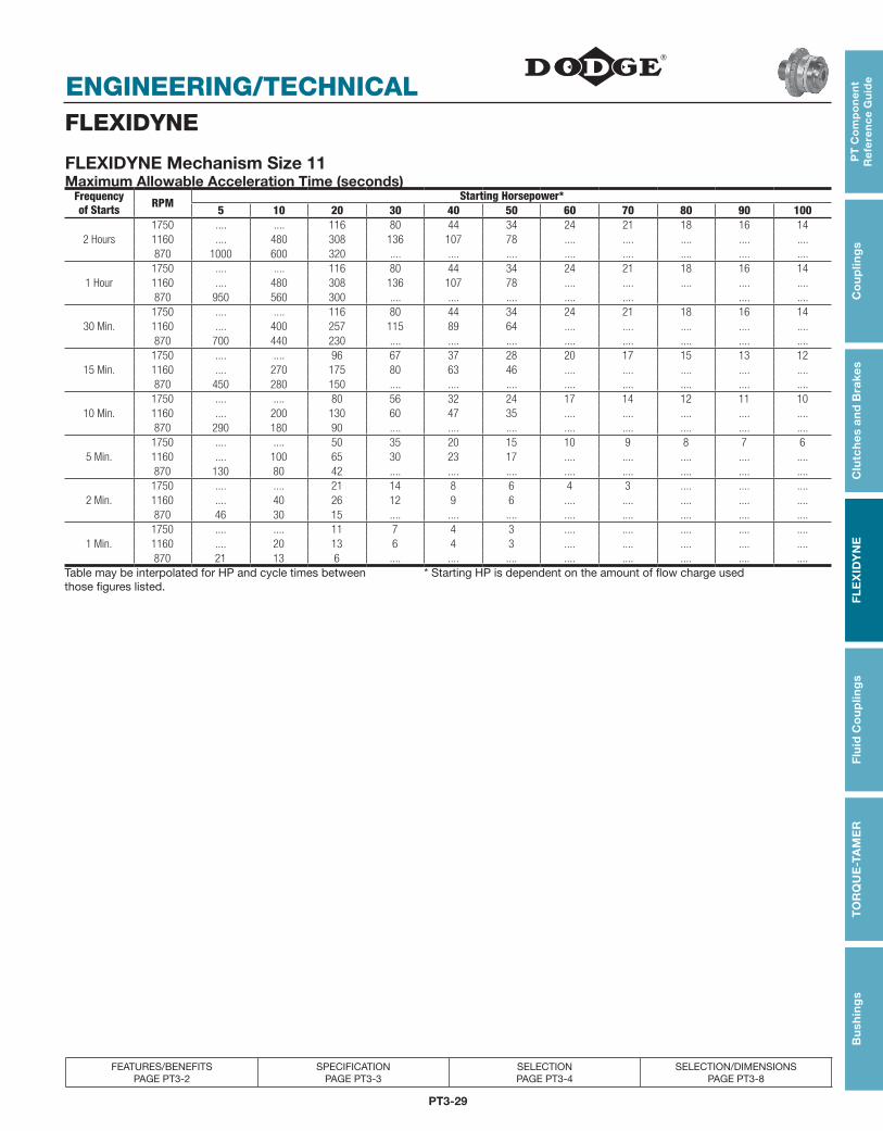
PT3-29
PT
Co
mp
on
en
t R
efe
ren
ce
Gu
ide
Co
up
ling
sC
lutc
hes
an
d B
rake
sF
LE
XID
YN
EF
luid
Co
up
ling
sT
OR
QU
E-T
AM
ER
Bu
shin
gs
ENGINEERING/TECHNICAL
FEATURES/BENEFITS PAGE PT3-2
SPECIFICATION PAGE PT3-3
SELECTION PAGE PT3-4
SELECTION/DIMENSIONS PAGE PT3-8
FLEXIDYNE
FLEXIDYNE Mechanism Size 11Maximum Allowable Acceleration Time (seconds)
Frequency of Starts RPM
Starting Horsepower*5 10 20 30 40 50 60 70 80 90 100
1750 .... .... 116 80 44 34 24 21 18 16 142 Hours 1160 .... 480 308 136 107 78 .... .... .... .... ....
870 1000 600 320 .... .... .... .... .... .... .... ....1750 .... .... 116 80 44 34 24 21 18 16 14
1 Hour 1160 .... 480 308 136 107 78 .... .... .... .... ....870 950 560 300 .... .... .... .... .... .... ....
1750 .... .... 116 80 44 34 24 21 18 16 1430 Min. 1160 .... 400 257 115 89 64 .... .... .... .... ....
870 700 440 230 .... .... .... .... .... .... .... ....1750 .... .... 96 67 37 28 20 17 15 13 12
15 Min. 1160 .... 270 175 80 63 46 .... .... .... .... ....870 450 280 150 .... .... .... .... .... .... .... ....
1750 .... .... 80 56 32 24 17 14 12 11 1010 Min. 1160 .... 200 130 60 47 35 .... .... .... .... ....
870 290 180 90 .... .... .... .... .... .... .... ....1750 .... .... 50 35 20 15 10 9 8 7 6
5 Min. 1160 .... 100 65 30 23 17 .... .... .... .... ....870 130 80 42 .... .... .... .... .... .... .... ....
1750 .... .... 21 14 8 6 4 3 .... .... ....2 Min. 1160 .... 40 26 12 9 6 .... .... .... .... ....
870 46 30 15 .... .... .... .... .... .... .... ....1750 .... .... 11 7 4 3 .... .... .... .... ....
1 Min. 1160 .... 20 13 6 4 3 .... .... .... .... ....870 21 13 6 .... .... .... .... .... .... .... ....
Table may be interpolated for HP and cycle times between those figures listed.
* Starting HP is dependent on the amount of flow charge used
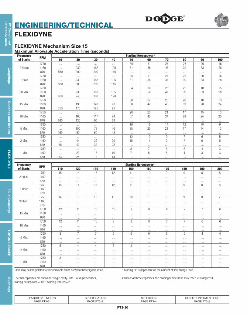
PT3-30
ENGINEERING/TECHNICAL
PT
Co
mp
on
en
t R
efe
ren
ce G
uid
eC
ou
plin
gs
Clu
tch
es an
d B
rakesF
LE
XID
YN
EF
luid
Co
up
ling
sT
OR
QU
E-TA
ME
RB
ush
ing
s
FEATURES/BENEFITS PAGE PT3-2
SPECIFICATION PAGE PT3-3
SELECTION PAGE PT3-4
SELECTION/DIMENSIONS PAGE PT3-8
FLEXIDYNE
FLEXIDYNE Mechanism Size 15Maximum Allowable Acceleration Time (seconds)
Frequency of Starts RPM
Starting Horsepower*10 20 30 40 50 60 70 80 90 100
1750 .... .... .... .... 35 31 27 23 20 162 Hours 1160 .... 230 167 105 81 56 47 39 33 28
870 560 300 200 145 .... .... .... .... .... ....1750 .... .... .... .... 35 31 27 23 20 16
1 Hour 1160 .... 230 167 105 81 56 47 39 33 28870 560 300 200 145 .... .... .... .... .... ....
1750 .... .... .... .... 34 30 26 22 18 1530 Min. 1160 .... 230 167 105 81 56 47 39 33 28
870 460 240 160 120 .... .... .... .... .... ....1750 .... .... .... .... 30 27 23 20 16 13
15 Min. 1160 .... 190 140 90 68 47 40 33 28 24870 350 170 125 90 .... .... .... .... .... ....
1750 .... .... .... .... 28 25 21 17 15 1310 Min. 1160 .... 160 117 74 57 40 34 28 24 20
870 260 130 95 68 .... .... .... .... .... ....1750 .... .... .... .... 19 16 14 12 10 9
5 Min. 1160 .... 100 73 46 35 25 21 17 14 12870 160 80 60 42 .... .... .... .... .... ....
1750 .... .... .... .... 12 10 9 7 6 52 Min. 1160 .... 44 32 20 15 11 9 7 6 5
870 85 42 32 22 .... .... .... .... .... ....1750 .... .... .... .... 8 7 6 5 4 3
1 Min. 1160 .... 23 17 10 7 5 5 4 3 3870 53 25 19 14 .... .... .... .... .... ....
Frequency of Starts RPM
Starting Horsepower*110 120 130 140 150 160 170 180 190 200
1750 15 14 13 12 11 10 9 9 8 82 Hours 1160 .... .... .... .... .... .... .... .... .... ....
870 .... .... .... .... .... .... .... .... .... ....1750 15 14 13 12 11 10 9 9 8 8
1 Hour 1160 .... .... .... .... .... .... .... .... .... ....870 .... .... .... .... .... .... .... .... .... ....
1750 14 13 12 11 10 10 9 9 8 730 Min. 1160 .... .... .... .... .... .... .... .... .... ....
870 .... .... .... .... .... .... .... .... .... ....1750 12 11 10 10 9 8 8 7 7 6
15 Min. 1160 .... .... .... .... .... .... .... .... .... ....870 .... .... .... .... .... .... .... .... .... ....
1750 12 11 10 9 8 8 7 7 6 610 Min. 1160 .... .... .... .... .... .... .... .... .... ....
870 .... .... .... .... .... .... .... .... .... ....1750 8 7 7 6 6 6 5 5 4 4
5 Min. 1160 .... .... .... .... .... .... .... .... .... ....870 .... .... .... .... .... .... .... .... .... ....
1750 5 4 4 3 3 .... .... .... .... ....2 Min. 1160 .... .... .... .... .... .... .... .... .... ....
870 .... .... .... .... .... .... .... .... .... ....1750 3 .... .... .... .... .... .... .... .... ....
1 Min. 1160 .... .... .... .... .... .... .... .... .... ....870 .... .... .... .... .... .... .... .... .... ....
Table may be interpolated for HP and cycle times between those figures listed * Starting HP is dependent on the amount of flow charge used.
Thermal capacities are shown for single cavity units. For duplex cavities, starting horsepower = (HP * Starting Torque%)/2
Caution: At these capacities, the housing temperature may reach 250 degrees F.
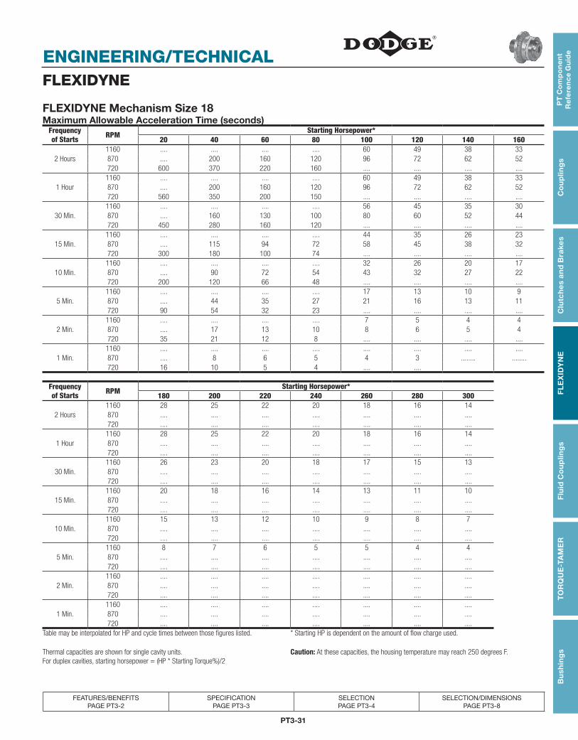
PT3-31
PT
Co
mp
on
en
t R
efe
ren
ce
Gu
ide
Co
up
ling
sC
lutc
hes
an
d B
rake
sF
LE
XID
YN
EF
luid
Co
up
ling
sT
OR
QU
E-T
AM
ER
Bu
shin
gs
ENGINEERING/TECHNICAL
FEATURES/BENEFITS PAGE PT3-2
SPECIFICATION PAGE PT3-3
SELECTION PAGE PT3-4
SELECTION/DIMENSIONS PAGE PT3-8
FLEXIDYNE
FLEXIDYNE Mechanism Size 18Maximum Allowable Acceleration Time (seconds)
Frequency of Starts RPM
Starting Horsepower*20 40 60 80 100 120 140 160
1160 .... .... .... .... 60 49 38 332 Hours 870 .... 200 160 120 96 72 62 52
720 600 370 220 160 .... .... .... ....1160 .... .... .... .... 60 49 38 33
1 Hour 870 .... 200 160 120 96 72 62 52720 560 350 200 150 .... .... .... ....1160 .... .... .... .... 56 45 35 30
30 Min. 870 .... 160 130 100 80 60 52 44720 450 280 160 120 .... .... .... ....1160 .... .... .... .... 44 35 26 23
15 Min. 870 .... 115 94 72 58 45 38 32720 300 180 100 74 .... .... .... ....1160 .... .... .... .... 32 26 20 17
10 Min. 870 .... 90 72 54 43 32 27 22720 200 120 66 48 .... .... .... ....1160 .... .... .... .... 17 13 10 9
5 Min. 870 .... 44 35 27 21 16 13 11720 90 54 32 23 .... .... .... ....1160 .... .... .... .... 7 5 4 4
2 Min. 870 .... 17 13 10 8 6 5 4720 35 21 12 8 .... .... .... ....
1160 .... .... .... .... .... .... .... ....1 Min. 870 .... 8 6 5 4 3 ........ ........
720 16 10 5 4 .... ....
Frequencyof Starts RPM
Starting Horsepower*180 200 220 240 260 280 300
1160 28 25 22 20 18 16 142 Hours 870 .... .... .... .... .... .... ....
720 .... .... .... .... .... .... .... 1160 28 25 22 20 18 16 14
1 Hour 870 .... .... .... .... .... .... ....720 .... .... .... .... .... .... ....
1160 26 23 20 18 17 15 1330 Min. 870 .... .... .... .... .... .... ....
720 .... .... .... .... .... .... ....1160 20 18 16 14 13 11 10
15 Min. 870 .... .... .... .... .... .... ....720 .... .... .... .... .... .... ....
1160 15 13 12 10 9 8 710 Min. 870 .... .... .... .... .... .... ....
720 .... .... .... .... .... .... ....1160 8 7 6 5 5 4 4
5 Min. 870 .... .... .... .... .... .... ....720 .... .... .... .... .... .... ....
1160 .... .... .... .... .... .... ....2 Min. 870 .... .... .... .... .... .... ....
720 .... .... .... .... .... .... .... 1160 .... .... .... .... .... .... ....
1 Min. 870 .... .... .... .... .... .... ....720 .... .... .... .... .... .... ....
Table may be interpolated for HP and cycle times between those figures listed. * Starting HP is dependent on the amount of flow charge used.
Thermal capacities are shown for single cavity units.For duplex cavities, starting horsepower = (HP * Starting Torque%)/2
Caution: At these capacities, the housing temperature may reach 250 degrees F.

PT3-32
NOTESPT
Co
mp
on
en
t R
efe
ren
ce G
uid
eC
ou
plin
gs
Clu
tch
es an
d B
rakesF
LE
XID
YN
EF
luid
Co
up
ling
sT
OR
QU
E-TA
ME
RB
ush
ing
s