Embed Size (px)
Citation preview
Attachment VI-2
Appendix A
CONSTRUCTION QUALITY ASSURANCE PLAN
FOR CONSTRUCTION OF
SURFACE IMPOUNDMENTS,
LANDFILLS, AND
LANDFILL CLOSURES
CONSTRUCTION QUALITY ASSURANCE PLAN FOR CONSTRUCTION OF SURFACE IMPOUNDMENTS
LANDFILLS, AND LANDFILL CLOSURES TABLE OF CONTENTS 1.0 INTRODUCTION ............................................................................................................. 1 2.0 PARTIES INVOLVED WITH CONSTRUCTION QUALITY ASSURANCE ........................ 2 3.0 CQA CONSULTANT’S PERSONNEL ORGANIZATION AND DUTIES ........................... 9 4.0 PROJECT MEETINGS ...................................................................................................12 5.0 CHANGE CONTROL PROCEDURES ............................................................................14 6.0 DOCUMENTATION ........................................................................................................16
Table 1 CQC/CQA Activities Table 2 Earthwork CQC Testing Requirements Table 3 Material Properties for HPDE Liner Table 4 Material Properties for Drainage Net Table 5 Material Properties for Geosynthetic Clay Liner Table 6 Material Properties for Filter Fabric Figure 1 Organizational Structure – Construction Quality Control/Construction Quality
Assurance Appendix A-1: Test Methods Appendix A-2: Permeability Test Methods
Attachment VI-2; Appendix A Revised October 2018 Construction Quality Assurance Plan Clean Harbors Grassy Mountain, LLC. Page 1 UTD991301748
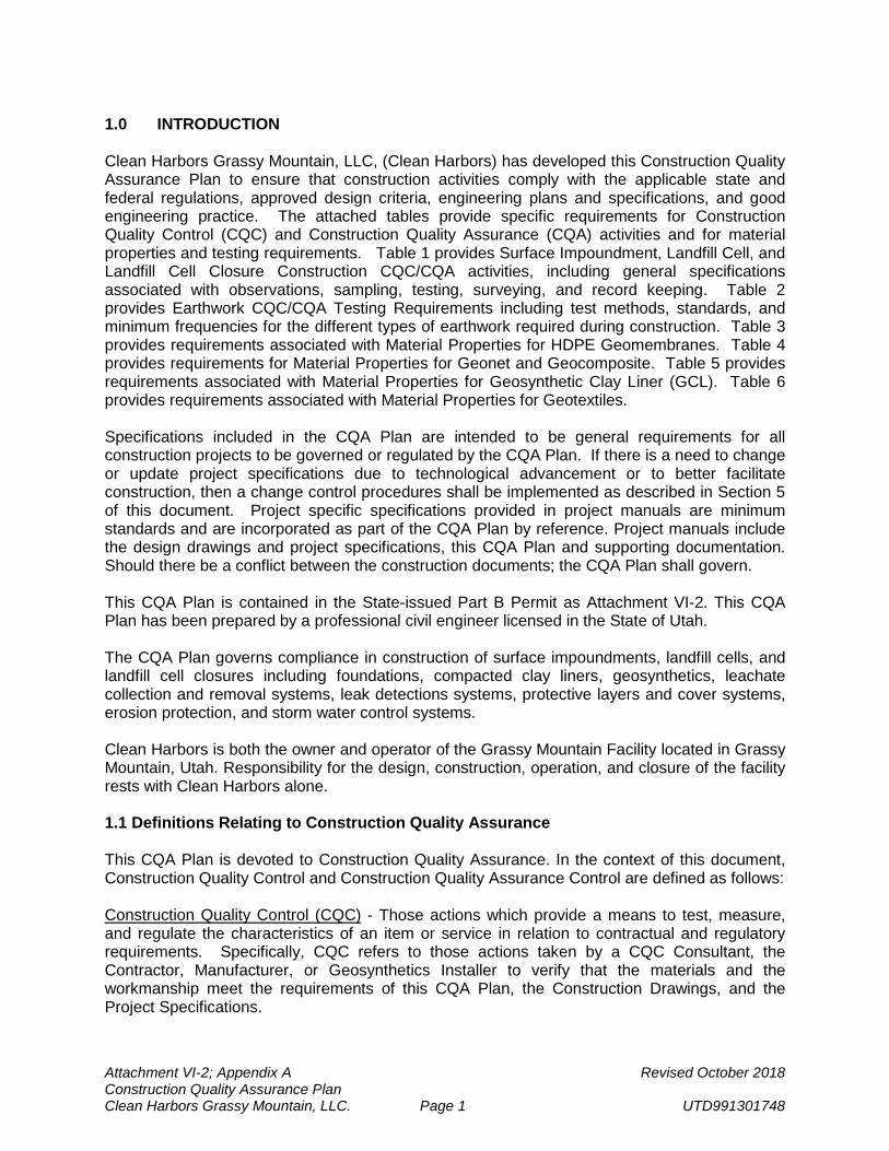
1.0 INTRODUCTION Clean Harbors Grassy Mountain, LLC, (Clean Harbors) has developed this Construction Quality Assurance Plan to ensure that construction activities comply with the applicable state and federal regulations, approved design criteria, engineering plans and specifications, and good engineering practice. The attached tables provide specific requirements for Construction Quality Control (CQC) and Construction Quality Assurance (CQA) activities and for material properties and testing requirements. Table 1 provides Surface Impoundment, Landfill Cell, and Landfill Cell Closure Construction CQC/CQA activities, including general specifications associated with observations, sampling, testing, surveying, and record keeping. Table 2 provides Earthwork CQC/CQA Testing Requirements including test methods, standards, and minimum frequencies for the different types of earthwork required during construction. Table 3 provides requirements associated with Material Properties for HDPE Geomembranes. Table 4 provides requirements for Material Properties for Geonet and Geocomposite. Table 5 provides requirements associated with Material Properties for Geosynthetic Clay Liner (GCL). Table 6 provides requirements associated with Material Properties for Geotextiles. Specifications included in the CQA Plan are intended to be general requirements for all construction projects to be governed or regulated by the CQA Plan. If there is a need to change or update project specifications due to technological advancement or to better facilitate construction, then a change control procedures shall be implemented as described in Section 5 of this document. Project specific specifications provided in project manuals are minimum standards and are incorporated as part of the CQA Plan by reference. Project manuals include the design drawings and project specifications, this CQA Plan and supporting documentation. Should there be a conflict between the construction documents; the CQA Plan shall govern. This CQA Plan is contained in the State-issued Part B Permit as Attachment VI-2. This CQA Plan has been prepared by a professional civil engineer licensed in the State of Utah. The CQA Plan governs compliance in construction of surface impoundments, landfill cells, and landfill cell closures including foundations, compacted clay liners, geosynthetics, leachate collection and removal systems, leak detections systems, protective layers and cover systems, erosion protection, and storm water control systems. Clean Harbors is both the owner and operator of the Grassy Mountain Facility located in Grassy Mountain, Utah. Responsibility for the design, construction, operation, and closure of the facility rests with Clean Harbors alone. 1.1 Definitions Relating to Construction Quality Assurance
This CQA Plan is devoted to Construction Quality Assurance. In the context of this document, Construction Quality Control and Construction Quality Assurance Control are defined as follows: Construction Quality Control (CQC) - Those actions which provide a means to test, measure, and regulate the characteristics of an item or service in relation to contractual and regulatory requirements. Specifically, CQC refers to those actions taken by a CQC Consultant, the Contractor, Manufacturer, or Geosynthetics Installer to verify that the materials and the workmanship meet the requirements of this CQA Plan, the Construction Drawings, and the Project Specifications.
Attachment VI-2; Appendix A Revised October 2018 Construction Quality Assurance Plan Clean Harbors Grassy Mountain, LLC. Page 2 UTD991301748
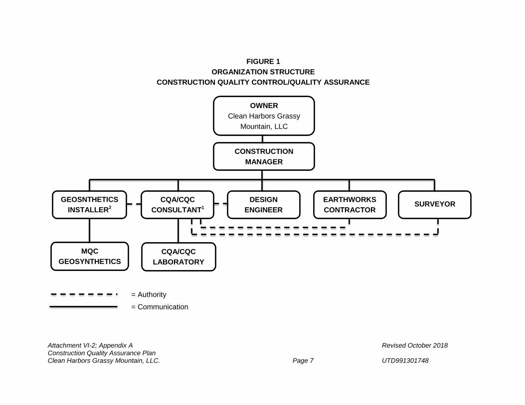
Construction Quality Assurance (CQA) - A planned and systematic pattern of means and actions designed to assure adequate confidence that materials and/or services meet contractual and regulatory requirements. Specifically, CQA refers to means and actions employed by the CQA Consultant to assure conformity of the Project “Work” with this CQA Plan, the Construction Drawings and Project Specifications. In the case of soil components, CQC is combined with CQA and is provided by the CQA Consultant. In the case of Work associated with geosynthetics and pipe installation, CQC is provided by the Manufacturer, the Geosynthetics Installer, and the Contractor. CQA testing of soil, pipe installations, concrete, and geosynthetic materials is provided by the CQA Consultant. 1.2 Specifications Should there be a disparity between project specifications, CQA Plan requirements, and any other documentation associated with construction or closure projects, the more stringent specification or requirement shall apply. 2.0 PARTIES INVOLVED WITH CONSTRUCTION QUALITY ASSURANCE This section defines the personnel involved with the development and implementation of the CQA Plan, as well as their qualifications. Figure 1 shows the organizational structure of the project, including lines of communication and authority. Names and contact information of selected personnel will be provided at the pre-construction meeting for each project. The Construction Manager (or his representative) shall be responsible for coordination with the Director of the Utah Division of Waste Management and Radiation Control (UDWMRC or Division) herein referred to as “Director”. The responsibilities and qualifications of parties are described below. 2.1 Design Engineer
Responsibilities
The Design Engineer is responsible for the design, Construction Drawings, and Project Specifications for construction of the Project. The Design Engineer is responsible to review and approve proposed design changes to the Project that comply with design, operational, and permitting requirements. The Design Engineer will also, as needed, review and approve corrective measures (resulting from construction deficiencies) that comply with design, operational, and permitting requirements.
Qualifications
The Design Engineer (Engineer of Record) shall be a qualified professional engineer, registered in the State of Utah. The Design Engineer should have expertise that demonstrates significant familiarity with piping, geosynthetics, soils, and storm drainage, as appropriate, including design and construction experience related to lining and leachate collection and removal systems. The Design Engineer shall have a minimum of three years of experience in the waste industry.
Attachment VI-2; Appendix A Revised October 2018 Construction Quality Assurance Plan Clean Harbors Grassy Mountain, LLC. Page 3 UTD991301748
2.2 Construction Manager
Responsibilities
The Construction Manager is responsible for managing the construction project, representing the Owner in administering construction contracts, implementation of the CQC/CQA Plan, and overseeing and coordinating activities between contractors and consultants under direct contract with the Owner. The Construction Manager may be a Clean Harbors employee or an employee of a consultant under contract with the Owner.
Qualifications
The Construction Manager shall have experience with landfill construction projects and have familiarity with earthwork construction and installation of geosynthetic materials.
2.3 Earthwork Contractor
Responsibilities
In this CQA Plan, the Contractor refers to a third party and/or Clean Harbors construction personnel, performing the Work in general accordance with this CQA Plan, the Construction Drawings, and the Project Specifications. The Earthwork Contractor will be responsible for the placement of the soils, appurtenant components of the liner systems, and final cover systems in accordance with contract documents. This work may include subgrade preparation; excavation, placement and compaction of engineered fill; placement of drainage aggregate and geosynthetic protective layers, installation of piping, installation of storm drainage and erosion control features, and coordination of work with the Geosynthetics Installer and other contractors and subcontractors. Qualifications
Qualifications of the Earthworks Contractor are specific to the construction contract and Project Specifications. The Earthworks Contractor should have a demonstrated history of successful earthwork construction and maintain current state and federal licenses as appropriate. 2.4 Resin Supplier
Responsibilities
The Resin Supplier produces and delivers the resin to the Geosynthetics Manufacturer.
Qualifications
Qualifications of the Resin Supplier are specific to the Manufacturer’s requirements. The Resin Supplier will have a demonstrated history of providing resin with consistent properties and meeting the requirements outlined in the Project Specifications.
Attachment VI-2; Appendix A Revised October 2018 Construction Quality Assurance Plan Clean Harbors Grassy Mountain, LLC. Page 4 UTD991301748
2.5 Geosynthetics Manufacturer(s)
Responsibilities
The Manufacturer(s) is responsible for the production of finished geosynthetic material (geomembrane, geotextile, geosynthetic clay liner, geocomposite, pipe, and other specified material, as appropriate) from appropriate raw (resin) materials.
Qualifications
The Manufacturer(s) will be able to provide sufficient production capacity and qualified personnel to meet the demands of the project.
2.6 Geosynthetics Installer
Responsibilities
The Geosynthetics Installer is responsible for development of geosynthetics placement plans, field handling, storage, placement, seaming, loading or anchoring against wind uplift, and other aspects of the geosynthetic material installation. The Geosynthetics Installer is also responsible for CQC testing of geosynthetics during installation and may be responsible for other specialized construction tasks.
Qualifications
The Geosynthetics Installer will be trained and qualified to install the geosynthetic materials of the type specified for each project. The Geosynthetics Installer shall meet the qualification requirements identified in the Design Drawings and Project Specifications. The Lead Geosynthetics Installer shall have, at a minimum, 10 million square feet of installation experience. The Field Supervisors working for the Geosynthetic Installer shall have, at a minimum, 2 million square feet of installation experience,
2.7 CQA Consultant
Responsibilities The CQA Consultant is an entity independent from the Owner, Contractor, Manufacturer, and Geosynthetics Installer. Responsibilities of the CQA Consultant include observation, testing, and documentation related to both CQC and CQA activities during of earthwork components of the Project. Responsibilities also include CQA activities during installation of piping, and the geosynthetic components of the Project. The CQA Consultant will also be responsible for providing a CQA certification for the Project in accordance with Utah Administrative Code R315-264-19(d) and for preparing CQA report at the completion of the Project. The CQA Report provides a summary of the earthwork, piping, and geosynthetics installation activities and associated CQA activities with supporting documentation. The certification and CQA report will be signed and sealed by the CQA Officer who will be a Professional Engineer registered in the State of Utah.
Attachment VI-2; Appendix A Revised October 2018 Construction Quality Assurance Plan Clean Harbors Grassy Mountain, LLC. Page 5 UTD991301748
The CQA Consultant will be responsible for obtaining and testing representative samples of components used, placed, and installed during construction of the Project as required by this CQA Plan and the Project Specifications. Tests will be conducted in accordance with ASTM or other applicable state or federal standards. The CQA Consultant will be responsible for observing earthwork, piping, geosynthetic, and cast-in-place concrete construction associated with the Project to verify that the components are installed in accordance with this CQA Plan, Construction Drawings, and Project Specifications.
Qualifications
The CQA Consultant is an established engineering firm with extensive experience in design and construction of surface impoundments and landfills. The CQA consultant will either possess the equipment, personnel, and licenses necessary to conduct the materials testing, or use an established laboratory with personnel, equipment, and licenses necessary to conduct the testing, required by the Project Plans, Specifications, and CQA Plan. The CQA Consultant will provide qualified staff for the project, as necessary, including a CQA Officer and a CQA Site Manager. The CQA Officer will be a professional engineer licensed by the State of Utah and shall have a minimum of three years of experience in the waste industry.
The CQA Consultant will be experienced with earthwork, installation of pipes and geosynthetic materials, cast-in-place concrete, and other construction practices that may be required for construction projects related to this CQA Plan. The CQA Consultant will be experienced in preparation of CQA Plans, and in preparation of general documentation, field documentation, field testing procedures, laboratory testing procedures, construction specifications, construction drawings, and CQA reports.
The CQA Site Manager will be specifically familiar with earthwork, installation of pipes and geosynthetics materials, cast-in-place concrete, and other construction practices that may be required and will be trained by the CQA Consultant in the duties of a CQA Site Manager. 2.8 Surveyor
Responsibilities
The Surveyor is a party that is responsible for surveying, documenting, and verifying the location of all significant components of the Work. The Surveyor will also provide record drawings showing final grades achieved with respect to design grades for the different components of earthwork.
Qualifications
The Surveyor will be an established surveying company with experience in providing surveying services in the State of Utah. The Surveyor will be professionally licensed by the State of Utah.
Attachment VI-2; Appendix A Revised October 2018 Construction Quality Assurance Plan Clean Harbors Grassy Mountain, LLC. Page 6 UTD991301748
2.9 CQA Laboratory
Responsibilities
The CQA Laboratory is a party, independent from the Contractor, Manufacturer, and Geosynthetics Installer. The CQA Laboratory is responsible for conducting CQA tests in accordance with American Society for Testing and Materials (ASTM) and other applicable testing standards on samples of soil and geosynthetic materials, in either an on-site or off-site laboratory.
Qualifications
The CQA Laboratory will have experience in testing soils and geosynthetic materials and will be familiar with ASTM and other applicable test standards.
Attachment VI-2; Appendix A Revised October 2018 Construction Quality Assurance Plan Clean Harbors Grassy Mountain, LLC. Page 7 UTD991301748
= Authority = Communication
OWNER Clean Harbors Grassy
Mountain, LLC
FIGURE 1 ORGANIZATION STRUCTURE
CONSTRUCTION QUALITY CONTROL/QUALITY ASSURANCE
CONSTRUCTION MANAGER
GEOSNTHETICS INSTALLER2
CQA/CQC CONSULTANT1
DESIGN ENGINEER
EARTHWORKS CONTRACTOR
SURVEYOR
MQC GEOSYNTHETICS
CQA/CQC LABORATORY
Attachment VI-2; Appendix A Revised October 2018 Construction Quality Assurance Plan Clean Harbors Grassy Mountain, LLC. Page 8 UTD991301748
Notes: 1) The CQA Consultant shall conduct CQC testing on Earthwork materials and installation. The CQA Consultant will not be responsible for providing
control for lines and grades of earthwork, this will be the responsibility of the Earthworks Contractor. 2) The Manufacturers Quality Control (MQC) testing and CQC testing of geosynthetic materials and installation will be performed by the Geosynthetics
Installer or Supplier and submitted to the CQA Consultant for review.
Attachment VI-2; Appendix A Revised October 2018 Construction Quality Assurance Plan Clean Harbors Grassy Mountain, LLC. Page 9 UTD991301748
3.0 CQA CONSULTANT’S PERSONNEL ORGANIZATION AND DUTIES
3.1 Overview The CQA Consultant will provide observations of construction and CQC activities, and will perform CQA materials testing, as appropriate, during construction projects. More specifically, the CQA Consultant will complete observations and documentation, and may provide testing for the following construction activities:
• excavation and screening of materials; • placement and compaction of prepared subgrades, compacted soil fill,
compacted clay liner, protective soil cover, trench and other backfills, and other soil components of liner and final cover systems;
• installation of geosynthetic clay liner (GCL); • installation of high density polyethylene (HDPE) geomembrane liner; • installation of drainage aggregate; • installation of geonet;
• installation of geotextile;
• installation of geocomposite (combined geonet and geotextile)
• placement of stone mulch (gravel armor plating erosion protection);
• installation of concrete; and • installation of piping.
The duties of the CQA personnel are provided in Table 1 and are generally discussed in the remainder of this section.
3.2 CQA Personnel
CQA Consultant’s personnel will include:
• the CQA Officer, who operates from the office of the CQA Consultant and
who conducts periodic visits to the site as required; • the CQA Site Manager, who is located at the site; and
• other CQA personnel, as needed, for each project.
The duties of the CQA Personnel are discussed in the following subsections.
Attachment VI-2; Appendix A Revised October 2018 Construction Quality Assurance Plan Clean Harbors Grassy Mountain, LLC. Page 10 UTD991301748
3.2.1 CQA Officer
The CQA Officer may also be the Design Engineer and shall supervise and be responsible for CQA activities, observations, and testing for the different phases and components required for construction of the Project. Specifically, the CQA Officer will:
• if other than the Design Engineer;
o coordinate and clarify design issues with the Design Engineer; o review and be familiar with this CQA Plan, Construction Drawings,
and Project Specifications; o review other site-specific documentation, unless otherwise agreed, for
familiarization and evaluation of project constructability only; o provide input regarding the design and documents reviewed for
consideration, but not necessarily implementation, leaving design responsibilities with the Design Engineer and not with the CQA Officer and the CQA Consultant;
• attend pre-construction, progress, and problem or work deficiency meetings,
as needed; • administer the CQA program (i.e., provide supervision of and manage on-site
CQA personnel, review field reports, and provide engineering review of CQA related activities);
• provide quality control of CQA documentation;
• conducts site visits; • review record (as-builts) drawings; • prepare the CQA report, including certification, documenting that the project
was constructed in accordance with the Construction Documents; and
• as a professional engineer licensed in the State of Utah, provide a stamp on the final CQA report and certification.
3.2.2 CQA Site Manager
The CQA Site Manager will:
• act as the on-site representative of the CQA Consultant; • attend CQA-related meetings (e.g., pre-construction, progress, and problem
or work deficiency (or designates a representative to attend meetings));
Attachment VI-2; Appendix A Revised October 2018 Construction Quality Assurance Plan Clean Harbors Grassy Mountain, LLC. Page 11 UTD991301748
• provide required information and documentation for preparation of the record (as-built) drawings;
• review record drawings for completeness and accuracy of the constructed
project based on prepared field documentation and notes; • review test results, documentation, and other submittals provided by
Contractor and CQC personnel; • review or assign locations for testing and sampling when required by the
CQA Plan; • oversee the collection and shipping of CQA laboratory test samples; • confirm calibration of CQA and CQC laboratory and on-site testing equipment
is complete, up-to-date, certified, and reported;
• review results of laboratory testing and make appropriate recommendations; • prepare a daily construction report summarizing construction activities for the
project;
• prepare a Weekly Report of the project for submittal to the Director; • review the Manufacturer’s QC documentation; • review the Geosynthetics Installer’s personnel qualifications for conformance
with those pre-approved for work on site; • document in the daily construction report and notify the CQA Officer and
Construction Manager of on-site activities that may be of concern in causing damage to the geosynthetic materials or other completed work;
• document, or cause to be documented, work that appears to be in
non-conformance with the design, project specifications, and/or CQA Plan requirements each day that non-conforming work appears to occur;
• document on a weekly basis a summary of work, if any, that appears to be in
non-conformance for the week and provide the following:
o anticipated remedial action(s) or resolution(s) to be taken; o time-frame/schedule associated with the remedial action(s) or
resolution(s); o actual measures taken to achieve final compliance; o description of corrective action(s) taken or to be taken to prevent
future occurrences; and
Attachment VI-2; Appendix A Revised October 2018 Construction Quality Assurance Plan Clean Harbors Grassy Mountain, LLC. Page 12 UTD991301748
• assist with the preparation of the CQA report.
3.2.3 Other CQA Personnel
Other CQA Personnel will be provided, as needed, to support the CQA Officer and CQA Site Manager in performing required CQA activities and responsibilities. The CQA Site Manager may also be the CQA Officer. 4.0 PROJECT MEETINGS
4.1 Project Coordination Meetings
Meetings of key project personnel are necessary to assure quality during construction, and to promote clear, open channels of communication. Therefore, Project Coordination Meetings are an essential element in the success of the project. Several types of Project Coordination Meetings are described below, including: (i) pre-construction meetings; (ii) progress meetings; and (iii) problem or work deficiency meetings. Meetings will be scheduled by the Construction Manager (or his delegate). The UDWMRC’s field representative will be adequately notified by the Construction Manager (or his delegate) of all meetings identified in this Plan and other meetings as determined necessary.
4.1.1 Pre-Construction Meeting(s)
A Pre-Construction Meeting will be held at the site prior to beginning construction activities associated with the Project. As a minimum, the Pre-Construction Meeting will be attended by the Earthwork Contractor, the Geosynthetics Installer, the CQA Consultant, the Design Engineer (if different than the CQA Officer), and the Construction Manager. The Construction Manager will notify the UDWMRC’s field representative of, and invite them to attend the Pre-Construction Meeting at least ten days prior to the proposed pre-construction meeting date. The Pre-Construction meeting may be attended in person or by conference call.
Specific items for discussion at the pre-construction meeting include the following:
• appropriate modifications or clarifications to the CQA Plan; • Construction Drawings and Project Specifications; • responsibilities of each party; • lines of authority and communication;
• names and contact information for involved parties (e.g., Construction
Manager, CQA Consultant, Earthwork Contractor; Geosynthetics Installer, etc.);
• methods for documenting and reporting, and for distributing documents and
reports;
Attachment VI-2; Appendix A Revised October 2018 Construction Quality Assurance Plan Clean Harbors Grassy Mountain, LLC. Page 13 UTD991301748
• protocols for observation and testing;
• acceptance and rejection criteria; • protocols for addressing and correcting deficiencies, repairs, and re-testing; • identifying work areas, and equipment and materials storage areas;
• identifying water sources and conditions;
• identifying material borrow sources and conditions;
• identifying clay drying and processing areas;
• identifying required submittals for the project;
• estimated time schedules for all project sequences and phases; • procedures for packaging and storing archive samples; • panel layout and numbering systems for panels and seams; • seaming procedures, and seam acceptance and rejection criteria; • repair procedures; and
• other information pertinent to the successful completion of the projects.
A separate Pre-Construction Meeting may be scheduled during earthwork construction, and prior to geosynthetics installation, to specifically address issues associated with installation of geosynthetic materials. Items presented above that are specific to installation of geosynthetic materials will be discussed in the Pre-Construction Meeting for geosynthetics installation should a separate meeting be held. The Construction Manager will conduct a site tour(s) to allow all attendees to observe the current site conditions and to review construction material and equipment storage locations, borrow sources, and clay drying and processing areas. A person in attendance at the meeting(s) will be appointed by the Construction Manager to record the discussions and decisions of the meeting(s) in the form of meeting minutes. Copies of the meeting minutes will be distributed to all attendees and to the UDWMRC’s field representative, irrespective of attendance.
4.1.2 Progress Meetings
Regular progress meetings will be held between the CQA Site Manager, the Contractor, Construction Manager, and other concerned parties participating in construction of the project. The UDWMRC’s representative for the project shall be notified of and invited to attend the
Attachment VI-2; Appendix A Revised October 2018 Construction Quality Assurance Plan Clean Harbors Grassy Mountain, LLC. Page 14 UTD991301748
progress meetings. These meetings will include discussions on the current progress of the project, planned future activities, coordination of schedules for the future activities, and revisions to the overall work plan and/or schedule. The meeting will be documented in meeting minutes prepared by a person designated by the CQA Site Manager at the beginning of the meeting. Meeting minutes will be distributed to all attendees and to the UDWMRC field representative. 4.1.3 Problem or Work Deficiency Meeting
A special meeting will be held when and if a significant problem or deficiency is present or appears likely to occur. The meeting will be scheduled by the Construction Manager or his representative. The meeting will be attended by the Construction Manager, Contractor, CQA Site Manager, UDWMRC representative(s) and other parties as appropriate. If the problem requires a design modification, the Design Engineer and certifying engineer should either be present, consulted prior to, or notified immediately upon conclusion of this meeting. The purpose of the work deficiency meeting is to define and resolve the problem or work deficiency as follows:
• define and discuss the problem or deficiency; • review alternative solutions; • select a suitable solution agreeable to all parties; and • implement an action plan to resolve the problem or deficiency.
A record of the meeting will be documented in the form of meeting minutes and copies will be distributed to all affected parties. A copy of the minutes will be retained in facility records. When correcting construction deficiencies, the Director, or his representative, will be provided notification so that they can be onsite to observe implementation of the solution. 5.0 CHANGE CONTROL PROCEDURES The need may arise for a change in design, engineering, construction conditions or specifications, and the CQA Plan during the project. Therefore, change control procedures have been established to ensure integrity of the design is not reduced upon incorporation of changes that may be needed or requested. Where a design change is necessary because of an incorrect or faulty design, or when a design change is recommended to better facilitate construction and operation, the design process and verification procedures themselves should be reviewed and modified, as necessary, to ensure the change meets the intent of the design and regulatory requirements. All change control procedures shall be done in accordance with Permit Conditions VI.C.4 and VI.C.6. Approved changes to the design, drawings, prints, construction conditions or specifications, etc. shall be stamped by the Design Engineer. The general change control procedure is as follows:
A. A change request may be initiated by, but not limited to, the Construction Manager, CQA Officer, Design Engineer, or Contractor.
B. All proposed changes in design, engineering, construction conditions or
specifications, and the CQA Plan shall be reviewed for applicability by the Design
Attachment VI-2; Appendix A Revised October 2018 Construction Quality Assurance Plan Clean Harbors Grassy Mountain, LLC. Page 15 UTD991301748
Engineer. After consulting the Construction Manager and others (CQA, contractor, etc.), and if determined to be justified by the Design Engineer, the scope of the change shall be subject to the same design control measures as those applied to the original design.
C. The Design Engineer shall submit the change to the Owner for approval. The
Owner will determine if the change is a minor change which does not require formal approval from UDWMRC; or, is major change which requires formal approval from the UDWMRC. If the permittee is unsure whether or not the Division might consider any proposed change to be minor, it is the permittee’s responsibility to communicate the proposed modification(s) to the Division for an opinion. The Division shall issue this opinion in a letter of acceptance or denial. Minor and major changes are described as follows:
1) Minor changes are defined as all changes that will in no way affect the
performance standard or the original intent of the plans and specification approved by UDWMRC. The minor changes will in no way reduce the effectiveness of the QA/QC effort used to ensure the quality and consistency of the materials and workmanship used to meet the performance standards in the plans and specifications approved by UDWMRC. Examples of minor changes include, but are not limited to, changes in testing procedures (ASTM updates), material property changes, grade changes that do not impact overall surface water flow patterns, use of pre-cast concrete elements in lieu of cast-in-place concrete elements, etc. Minor changes shall conform to the original design intent. All minor changes will be clearly identified, described and justified in the construction certification report. Minor changes may be implemented immediately and shall be documented as outlined in the following paragraphs. The UDWMRC will allow the permittee to make minor modifications to design, engineering, construction conditions and specifications, and the CQA Plan without prior approval by the Division, provided that the requirements above are met.
C2) Major changes are defined as changes which require a permit
modification pursuant to R315-270-42, Appendix I. Major changes shall be reviewed by the Owner, the CQA Officer, and the Design Engineer. Clean Harbors shall receive approval from the Director prior to implementation of major changes.
D. Upon approval, the Construction Manager shall communicate the change to all affected design, construction, CQC, and CQA personnel. The Construction Manager may issue an amendment to the applicable documents and submit the amendment to the CQA Officer (or designee) for distribution to critical personnel. The Construction Manager may also communicate the change via a Field Directive distributed to critical personnel.
E. Documentation of changes shall be included in the Construction Certification
Report. F. Record (as-built) drawings of the project shall reflect changes made as a result of
the change control procedure process.
Attachment VI-2; Appendix A Revised October 2018 Construction Quality Assurance Plan Clean Harbors Grassy Mountain, LLC. Page 16 UTD991301748
6.0 DOCUMENTATION 6.1 Overview
An effective CQA Plan depends largely on recognition of construction activities that should be observed and on providing specific assignments and responsibilities for observation of each activity. This is most effectively accomplished and verified by review of CQC activities and documentation, and by documentation associated with CQA activities. The CQA Consultant will document in the CQA Report that all quality assurance requirements have been addressed and satisfied.
The CQA Site Manager will provide the Construction Manager with signed descriptive reports, data sheets, and logs to verify that observation activities have been carried out. The CQA Site Manager will also maintain, at the job site, a complete file of Construction Drawings, CQA Plan, checklists, test procedures, daily logs, laboratory and field testing records, and other pertinent documents.
6.2 Daily Recordkeeping
Preparation of daily CQA documentation will consist of daily construction reports prepared by the CQA Site Manager which may include CQA observation logs and CQA testing data sheets, as applicable, on each day construction activities occur. This information will be reviewed regularly by the CQA Officer and will be regularly submitted to the Construction Manager for review. After review by the Construction Manager, the daily construction reports will be sent by email to the Director or his representative.
The daily construction reports, observation logs, and testing data sheets prepared by the CQA Site Manager will document construction activities observed each day. At a minimum, these reports, logs, and data sheets will include the following information:
• the date, project name, location, and other project identification; • a summary of the weather conditions; • major equipment and the number of personnel on the project; • a summary of meetings held and attendees; • a summary of the types of construction activities and where the construction
occurred; • a description of materials used and references to the test results and
documentation; • identification of deficient work and materials; • reference to results of re-testing for corrected “deficient work;”

Attachment VI-2; Appendix A Revised October 2018 Construction Quality Assurance Plan Clean Harbors Grassy Mountain, LLC. Page 17 UTD991301748
• an identifying system for cross referencing corrective work and associated re-testing;
• a description of observations made and used to evaluate construction; • a summary of the results of CQA test data; • calibration variations that may have occurred with test equipment and actions
taken, if necessary, as a result of those variations; • decisions made regarding acceptance of units of work and/or units of work
requiring corrective actions based on substandard test results;
• a discussion of agreements made between the interested parties which may affect the work; and
• signature of the respective CQA Site Manager.
6.3 Weekly Report A Weekly Report will be provided to the Director that will consist of, at a minimum, a summary of the work completed and documented during the previous week in accordance with this plan. The reporting period is from Sunday through Saturday. The report will be provided by the second Monday following the close of the reporting week. Weekly Reports will be required to be submitted commencing at the date of the Pre-Construction meeting and until the construction of the project is complete. 6.4 Construction Problems and Resolutions Data Sheets
Construction Problems and Resolution Data Sheets will be kept to track problems that occur during construction and to document when resolutions or corrective actions are complete. The construction and resolutions data sheets will be kept current by the CQA Site Manager and will be submitted to the Construction Manager with the Daily Construction Reports on days the problems and resolutions occur. The Construction Problems and Resolution Data Sheets will describe the problem(s) and respective resolution(s) and that dates the problems and resolutions occur so they can be cross-referenced, by date, to daily construction reports, observation record, and testing data sheets where problems and resolutions occurred. The Construction Problems and Resolution Sheets shall be provided to the Director along with the applicable Daily Construction Report. The following information, where available, will be provided:
• an identifying date for observation of each problem and for implementation of
the associated resolution in order provide cross-referencing with dates of other reports and records;
• a detailed description of the problem or deficiency; • the location and probable cause of the problem or deficiency;
Attachment VI-2; Appendix A Revised October 2018 Construction Quality Assurance Plan Clean Harbors Grassy Mountain, LLC. Page 18 UTD991301748
• documentation of the response to the problem or deficiency; • final results of responses; • measures taken to minimize a similar problem from occurring in the future;
and • signature of the CQA Site Manager and a signature indicating concurrence by
the Construction Manager.
The Construction Manager will be made aware of significant recurring nonconformance with the Construction Drawings, Project Specifications, or CQA Plan. The cause of the nonconformance will be determined and appropriate changes will be discussed with the entities involved in the construction process. Resulting changes in construction procedures, design, or specifications will be recommended, as appropriate. Changes in the design or specifications will be submitted to the Design Engineer for approval in accordance with Change Control Procedure requirements. The completed problems and resolutions data sheets will be signed by the CQA Site Manager and CQA Officer and will be included in the CQA Report at the completion of the project.
6.5 Photographic Documentation
Photographs will be taken in order to serve as a pictorial record of work progress, problems encountered, and mitigation activities. Photographs used for documentation will be identified with the date, time, location, and a description of the photograph in order to provide cross-reference to the date of other project reports and records.
6.6 Design and/or Specification Changes
Design and/or specification changes will be documented according to the requirements of the Change Control Procedures. 6.7 CQA Report
At the completion of the Project, the CQA Consultant will submit to the Owner the CQA report signed and sealed by a Professional Engineer licensed in the State of Utah. The CQA report will acknowledge: (i) that the work has been performed in substantial compliance with the CQA Plan and applicable State and Federal regulations; (ii) sampling and testing has been conducted at the appropriate frequencies; and (iii) that the report and its appendices or attachments include the necessary supporting information. At a minimum, this report and the supporting documentation will include:
• a summary report describing the CQA activities and indicating compliance
with the Construction Drawings, Project Specifications, and CQA Plan which is signed and sealed by the CQA Officer;
• Daily and weekly construction reports;
Attachment VI-2; Appendix A Revised October 2018 Construction Quality Assurance Plan Clean Harbors Grassy Mountain, LLC. Page 19 UTD991301748
• a summary of earthwork testing, including failures, corrective measures, and
retest results; • record drawings of the project;
• record drawings provided by the Surveyor of finish grades for soil
components of the project; • contractor personnel resumes and qualifications for the geosynthetics
installer;
• Manufacturers’ quality control documentation; • a summary of CQA/CQC testing, including failures, corrective measures, and
retest results, including:
o Trial seams, o Non-destructive testing of field seams, and o Destructive testing of field seams;
• documentation that seaming, testing, and repairs were observed by the CQA
Consultant; and • records (data forms and record drawings) of seams, panels (with panel and
manufacturer roll numbers), destructive test sample locations, and non-destructive test results.
The record drawings will include scale drawings depicting the location of the construction and details pertaining to the extent of construction (e.g., depths, plan dimensions, elevations, soil component thicknesses). Record drawings providing grade verification for the surface of earthwork components (subgrades, embankments, clay liners, protective covers, etc.) will be prepared by a qualified Professional Land Surveyor registered in the State of Utah. These documents will be reviewed by the CQA Consultant and included as part of the CQA Report. The CQA Report will be submitted to the appropriate regulatory agencies within sixty (60) days of completion of the project.
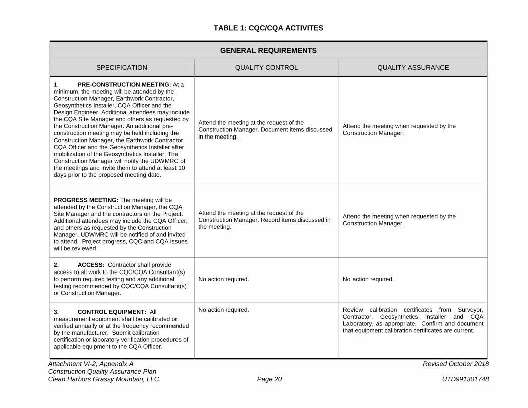
TABLE 1: CQC/CQA ACTIVITES
Attachment VI-2; Appendix A Revised October 2018 Construction Quality Assurance Plan Clean Harbors Grassy Mountain, LLC. Page 20 UTD991301748
GENERAL REQUIREMENTS
SPECIFICATION QUALITY CONTROL QUALITY ASSURANCE
1. PRE-CONSTRUCTION MEETING: At a minimum, the meeting will be attended by the Construction Manager, Earthwork Contractor, Geosynthetics Installer, CQA Officer and the Design Engineer. Additional attendees may include the CQA Site Manager and others as requested by the Construction Manager. An additional pre-construction meeting may be held including the Construction Manager, the Earthwork Contractor, CQA Officer and the Geosynthetics Installer after mobilization of the Geosynthetics Installer. The Construction Manager will notify the UDWMRC of the meetings and invite them to attend at least 10 days prior to the proposed meeting date.
Attend the meeting at the request of the Construction Manager. Document items discussed in the meeting.
Attend the meeting when requested by the Construction Manager.
PROGRESS MEETING: The meeting will be attended by the Construction Manager, the CQA Site Manager and the contractors on the Project. Additional attendees may include the CQA Officer, and others as requested by the Construction Manager. UDWMRC will be notified of and invited to attend. Project progress, CQC and CQA issues will be reviewed.
Attend the meeting at the request of the Construction Manager. Record items discussed in the meeting.
Attend the meeting when requested by the Construction Manager.
2. ACCESS: Contractor shall provide access to all work to the CQC/CQA Consultant(s) to perform required testing and any additional testing recommended by CQC/CQA Consultant(s) or Construction Manager.
No action required. No action required.
3. CONTROL EQUIPMENT: All measurement equipment shall be calibrated or verified annually or at the frequency recommended by the manufacturer. Submit calibration certification or laboratory verification procedures of applicable equipment to the CQA Officer.
No action required. Review calibration certificates from Surveyor, Contractor, Geosynthetics Installer and CQA Laboratory, as appropriate. Confirm and document that equipment calibration certificates are current.
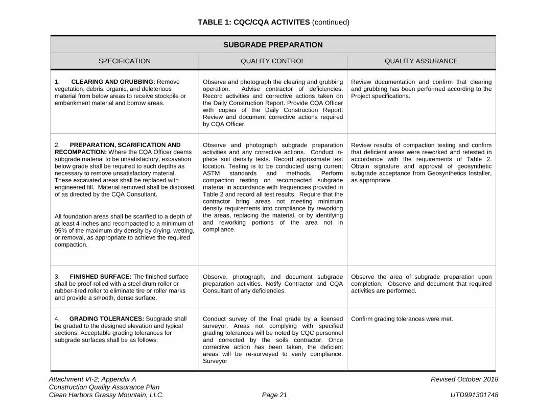
TABLE 1: CQC/CQA ACTIVITES (continued)
Attachment VI-2; Appendix A Revised October 2018 Construction Quality Assurance Plan Clean Harbors Grassy Mountain, LLC. Page 21 UTD991301748
SUBGRADE PREPARATION
SPECIFICATION QUALITY CONTROL QUALITY ASSURANCE
1. CLEARING AND GRUBBING: Remove vegetation, debris, organic, and deleterious material from below areas to receive stockpile or embankment material and borrow areas.
Observe and photograph the clearing and grubbing operation. Advise contractor of deficiencies. Record activities and corrective actions taken on the Daily Construction Report. Provide CQA Officer with copies of the Daily Construction Report. Review and document corrective actions required by CQA Officer.
Review documentation and confirm that clearing and grubbing has been performed according to the Project specifications.
2. PREPARATION, SCARIFICATION AND RECOMPACTION: Where the CQA Officer deems subgrade material to be unsatisfactory, excavation below grade shall be required to such depths as necessary to remove unsatisfactory material. These excavated areas shall be replaced with engineered fill. Material removed shall be disposed of as directed by the CQA Consultant.
All foundation areas shall be scarified to a depth of at least 4 inches and recompacted to a minimum of 95% of the maximum dry density by drying, wetting, or removal, as appropriate to achieve the required compaction.
Observe and photograph subgrade preparation activities and any corrective actions. Conduct in-place soil density tests. Record approximate test location. Testing is to be conducted using current ASTM standards and methods. Perform compaction testing on recompacted subgrade material in accordance with frequencies provided in Table 2 and record all test results. Require that the contractor bring areas not meeting minimum density requirements into compliance by reworking the areas, replacing the material, or by identifying and reworking portions of the area not in compliance.
Review results of compaction testing and confirm that deficient areas were reworked and retested in accordance with the requirements of Table 2. Obtain signature and approval of geosynthetic subgrade acceptance from Geosynthetics Installer, as appropriate.
3. FINISHED SURFACE: The finished surface shall be proof-rolled with a steel drum roller or rubber-tired roller to eliminate tire or roller marks and provide a smooth, dense surface.
Observe, photograph, and document subgrade preparation activities. Notify Contractor and CQA Consultant of any deficiencies.
Observe the area of subgrade preparation upon completion. Observe and document that required activities are performed.
4. GRADING TOLERANCES: Subgrade shall be graded to the designed elevation and typical sections. Acceptable grading tolerances for subgrade surfaces shall be as follows:
Conduct survey of the final grade by a licensed surveyor. Areas not complying with specified grading tolerances will be noted by CQC personnel and corrected by the soils contractor. Once corrective action has been taken, the deficient areas will be re-surveyed to verify compliance. Surveyor
Confirm grading tolerances were met.
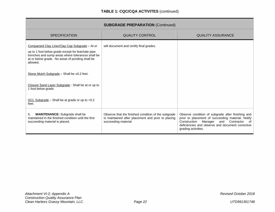
TABLE 1: CQC/CQA ACTIVITES (continued)
Attachment VI-2; Appendix A Revised October 2018 Construction Quality Assurance Plan Clean Harbors Grassy Mountain, LLC. Page 22 UTD991301748
SUBGRADE PREPARATION (Continued)
SPECIFICATION QUALITY CONTROL QUALITY ASSURANCE
Compacted Clay Liner/Clay Cap Subgrade – At or
up to 1 foot below grade except for leachate pipe trenches and sump areas where tolerances shall be at or below grade. No areas of ponding shall be allowed.
Stone Mulch Subgrade – Shall be ±0.2 feet.
Closure Sand Layer Subgrade - Shall be at or up to 1 foot below grade.
GCL Subgrade – Shall be at grade or up to +0.2 feet.
will document and certify final grades.
5. MAINTENANCE: Subgrade shall be maintained in the finished condition until the first succeeding material is placed.
Observe that the finished condition of the subgrade is maintained after placement and prior to placing succeeding material.
Observe condition of subgrade after finishing and prior to placement of succeeding material. Notify Construction Manager and Contractor of deficiencies and observe and document corrective grading activities.
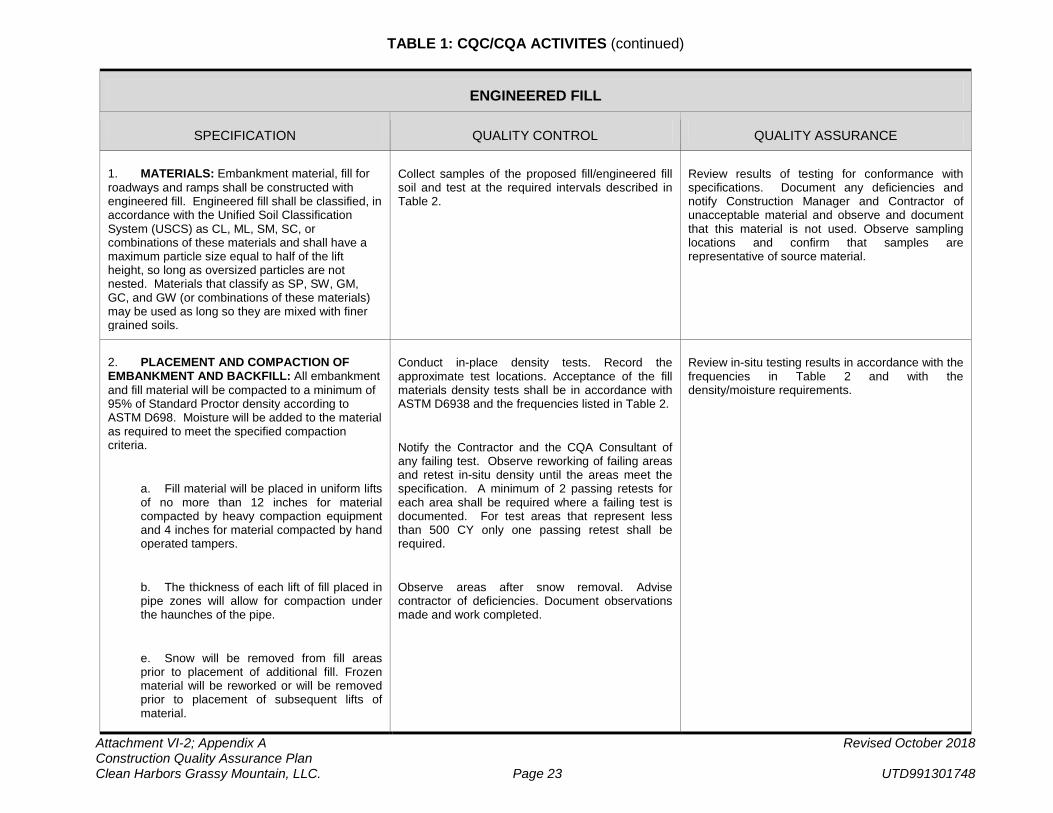
TABLE 1: CQC/CQA ACTIVITES (continued)
Attachment VI-2; Appendix A Revised October 2018 Construction Quality Assurance Plan Clean Harbors Grassy Mountain, LLC. Page 23 UTD991301748
ENGINEERED FILL
SPECIFICATION QUALITY CONTROL QUALITY ASSURANCE
1. MATERIALS: Embankment material, fill for roadways and ramps shall be constructed with engineered fill. Engineered fill shall be classified, in accordance with the Unified Soil Classification System (USCS) as CL, ML, SM, SC, or combinations of these materials and shall have a maximum particle size equal to half of the lift height, so long as oversized particles are not nested. Materials that classify as SP, SW, GM, GC, and GW (or combinations of these materials) may be used as long so they are mixed with finer grained soils.
Collect samples of the proposed fill/engineered fill soil and test at the required intervals described in Table 2.
Review results of testing for conformance with specifications. Document any deficiencies and notify Construction Manager and Contractor of unacceptable material and observe and document that this material is not used. Observe sampling locations and confirm that samples are representative of source material.
2. PLACEMENT AND COMPACTION OF EMBANKMENT AND BACKFILL: All embankment and fill material will be compacted to a minimum of 95% of Standard Proctor density according to ASTM D698. Moisture will be added to the material as required to meet the specified compaction criteria.
a. Fill material will be placed in uniform lifts of no more than 12 inches for material compacted by heavy compaction equipment and 4 inches for material compacted by hand operated tampers.
b. The thickness of each lift of fill placed in pipe zones will allow for compaction under the haunches of the pipe.
e. Snow will be removed from fill areas prior to placement of additional fill. Frozen material will be reworked or will be removed prior to placement of subsequent lifts of material.
Conduct in-place density tests. Record the approximate test locations. Acceptance of the fill materials density tests shall be in accordance with ASTM D6938 and the frequencies listed in Table 2.
Notify the Contractor and the CQA Consultant of any failing test. Observe reworking of failing areas and retest in-situ density until the areas meet the specification. A minimum of 2 passing retests for each area shall be required where a failing test is documented. For test areas that represent less than 500 CY only one passing retest shall be required.
Observe areas after snow removal. Advise contractor of deficiencies. Document observations made and work completed.
Review in-situ testing results in accordance with the frequencies in Table 2 and with the density/moisture requirements.
TABLE 1: CQC/CQA ACTIVITES (continued)
Attachment VI-2; Appendix A Revised October 2018 Construction Quality Assurance Plan Clean Harbors Grassy Mountain, LLC. Page 24 UTD991301748
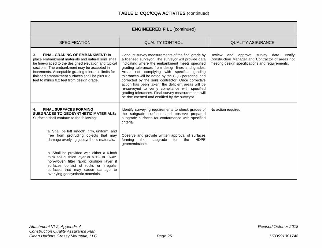
TABLE 1: CQC/CQA ACTIVITES (continued)
Attachment VI-2; Appendix A Revised October 2018 Construction Quality Assurance Plan Clean Harbors Grassy Mountain, LLC. Page 25 UTD991301748
ENGINEERED FILL (continued)
SPECIFICATION QUALITY CONTROL QUALITY ASSURANCE
3. FINAL GRADING OF EMBANKMENT: In-place embankment materials and natural soils shall be fine-graded to the designed elevation and typical sections. The embankment may be accepted in increments. Acceptable grading tolerance limits for finished embankment surfaces shall be plus 0.2 feet to minus 0.2 feet from design grade.
Conduct survey measurements of the final grade by a licensed surveyor. The surveyor will provide data indicating where the embankment meets specified grading tolerances from design lines and grades. Areas not complying with specified grading tolerances will be noted by the CQC personnel and corrected by the soils contractor. Once corrective action has been taken, the deficient areas will be re-surveyed to verify compliance with specified grading tolerances. Final survey measurements will be documented and certified by the surveyor.
Review and approve survey data. Notify Construction Manager and Contractor of areas not meeting design specifications and requirements.
4. FINAL SURFACES FORMING SUBGRADES TO GEOSYNTHETIC MATERIALS: Surfaces shall conform to the following:
a. Shall be left smooth, firm, uniform, and free from protruding objects that may damage overlying geosynthetic materials.
b. Shall be provided with either a 6-inch thick soil cushion layer or a 12- or 16-oz. non-woven filter fabric cushion layer if surfaces consist of rocks or irregular surfaces that may cause damage to overlying geosynthetic materials.
Identify surveying requirements to check grades of the subgrade surfaces and observe prepared subgrade surfaces for conformance with specified criteria.
Observe and provide written approval of surfaces forming the subgrade for the HDPE geomembranes.
No action required.
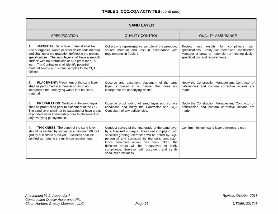
TABLE 1: CQC/CQA ACTIVITES (continued)
Attachment VI-2; Appendix A Revised October 2018 Construction Quality Assurance Plan Clean Harbors Grassy Mountain, LLC. Page 26 UTD991301748
SAND LAYER
SPECIFICATION QUALITY CONTROL QUALITY ASSURANCE
1. MATERIAL: Sand layer material shall be free of organics, waste or other deleterious material and shall meet the gradation defined in the project specifications. The sand layer shall have a smooth surface with no protrusions or ruts great than 1/2 –inch. The Contractor shall identify potential material source and submit samples to the CQA Officer.
Collect one representative sample of the proposed source material and test in accordance with requirements in Table 2.
Review test results for compliance with specifications. Notify Contractor and Construction Manager of areas or materials not meeting design specifications and requirements.
2. PLACEMENT: Placement of the sand layer shall be performed in a manner so as to not incorporate the underlying waste into the sand material.
Observe and document placement of the sand layer is placed in a manner that does not incorporate the underlying waste.
Notify the Construction Manager and Contractor of deficiencies and confirm corrective actions are made.
3. PREPARATION: Surface of the sand layer shall be proof rolled prior to placement of the GCL. The sand layer shall not be saturated or have areas of ponded water immediately prior to placement of any overlying geosynthetics.
Observe proof rolling of sand layer and surface conditions and notify the Contractor and CQA Consultant of any deficiencies.
Notify the Construction Manager and Contractor of deficiencies and confirm corrective actions are made.
4. THICKNESS: The depth of the sand layer should be verified by survey on a minimum 60 foot grid by a licensed surveyor. Thickness shall be verified as meeting the minimum requirement.
Conduct survey of the final grade of the sand layer by a licensed surveyor. Areas not complying with specified grading tolerances will be noted by CQC personnel and corrected by the soils contractor. Once corrective action has been taken, the deficient areas will be re-surveyed to verify compliance. Surveyor will document and certify sand layer thickness.
Confirm minimum sand layer thickness is met.
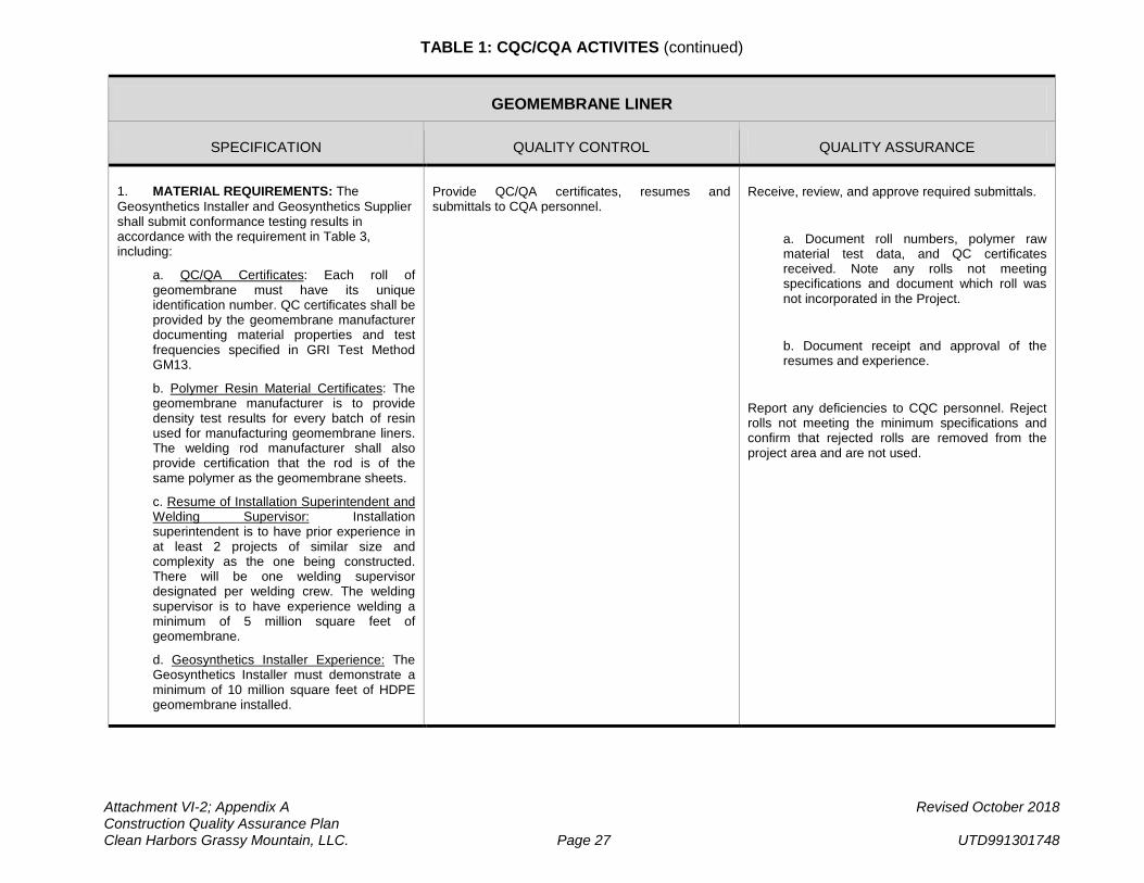
TABLE 1: CQC/CQA ACTIVITES (continued)
Attachment VI-2; Appendix A Revised October 2018 Construction Quality Assurance Plan Clean Harbors Grassy Mountain, LLC. Page 27 UTD991301748
GEOMEMBRANE LINER
SPECIFICATION QUALITY CONTROL QUALITY ASSURANCE
1. MATERIAL REQUIREMENTS: The Geosynthetics Installer and Geosynthetics Supplier shall submit conformance testing results in accordance with the requirement in Table 3, including:
a. QC/QA Certificates: Each roll of geomembrane must have its unique identification number. QC certificates shall be provided by the geomembrane manufacturer documenting material properties and test frequencies specified in GRI Test Method GM13.
b. Polymer Resin Material Certificates: The geomembrane manufacturer is to provide density test results for every batch of resin used for manufacturing geomembrane liners. The welding rod manufacturer shall also provide certification that the rod is of the same polymer as the geomembrane sheets.
c. Resume of Installation Superintendent and Welding Supervisor: Installation superintendent is to have prior experience in at least 2 projects of similar size and complexity as the one being constructed. There will be one welding supervisor designated per welding crew. The welding supervisor is to have experience welding a minimum of 5 million square feet of geomembrane.
d. Geosynthetics Installer Experience: The Geosynthetics Installer must demonstrate a minimum of 10 million square feet of HDPE geomembrane installed.
Provide QC/QA certificates, resumes and submittals to CQA personnel.
Receive, review, and approve required submittals.
a. Document roll numbers, polymer raw material test data, and QC certificates received. Note any rolls not meeting specifications and document which roll was not incorporated in the Project.
b. Document receipt and approval of the resumes and experience.
Report any deficiencies to CQC personnel. Reject rolls not meeting the minimum specifications and confirm that rejected rolls are removed from the project area and are not used.
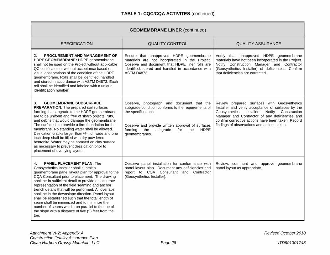
TABLE 1: CQC/CQA ACTIVITES (continued)
Attachment VI-2; Appendix A Revised October 2018 Construction Quality Assurance Plan Clean Harbors Grassy Mountain, LLC. Page 28 UTD991301748
GEOMEMBRANE LINER (continued)
SPECIFICATION QUALITY CONTROL QUALITY ASSURANCE
2. PROCUREMENT AND MANAGEMENT OF HDPE GEOMEMBRANE: HDPE geomembrane shall not be used on the Project without applicable QC certificates or without acceptance based on visual observations of the condition of the HDPE geomembrane. Rolls shall be identified, handled and stored in accordance with ASTM D4873. Each roll shall be identified and labeled with a unique identification number.
Ensure that unapproved HDPE geomembrane materials are not incorporated in the Project. Observe and document that HDPE liner rolls are identified, stored and handled in accordance with ASTM D4873.
Verify that unapproved HDPE geomembrane materials have not been incorporated in the Project. Notify Construction Manager and Contractor (Geosynthetics Installer) of deficiencies. Confirm that deficiencies are corrected.
3. GEOMEMBRANE SUBSURFACE PREPARATION: The prepared soil surfaces forming the subgrade to the HDPE geomembrane are to be uniform and free of sharp objects, ruts, and debris that would damage the geomembrane. The surface is to provide a firm foundation for the membrane. No standing water shall be allowed. Desication cracks larger than ¼-inch wide and one inch deep shall be filled with dry powdered bentonite. Water may be sprayed on clay surface as necessary to prevent dessication prior to placement of overlying layers.
Observe, photograph and document that the subgrade condition conforms to the requirements of the specifications.
Observe and provide written approval of surfaces forming the subgrade for the HDPE geomembranes.
Review prepared surfaces with Geosynthetics Installer and verify acceptance of surfaces by the Geosynthetics Installer. Notify Construction Manager and Contractor of any deficiencies and confirm corrective actions have been taken. Record findings of observations and actions taken.
4. PANEL PLACEMENT PLAN: The Geosynthetics Installer shall submit a geomembrane panel layout plan for approval to the CQA Consultant prior to placement. The drawing shall be in sufficient detail to provide an accurate representation of the field seaming and anchor trench details that will be performed. All overlaps shall be in the downslope direction. Panel layout shall be established such that the total length of seam shall be minimized and to minimize the number of seams which run parallel to the toe of the slope with a distance of five (5) feet from the toe.
Observe panel installation for conformance with panel layout plan. Document any deficiencies and report to CQA Consultant and Contractor (Geosynthetics Installer).
Review, comment and approve geomembrane panel layout as appropriate.
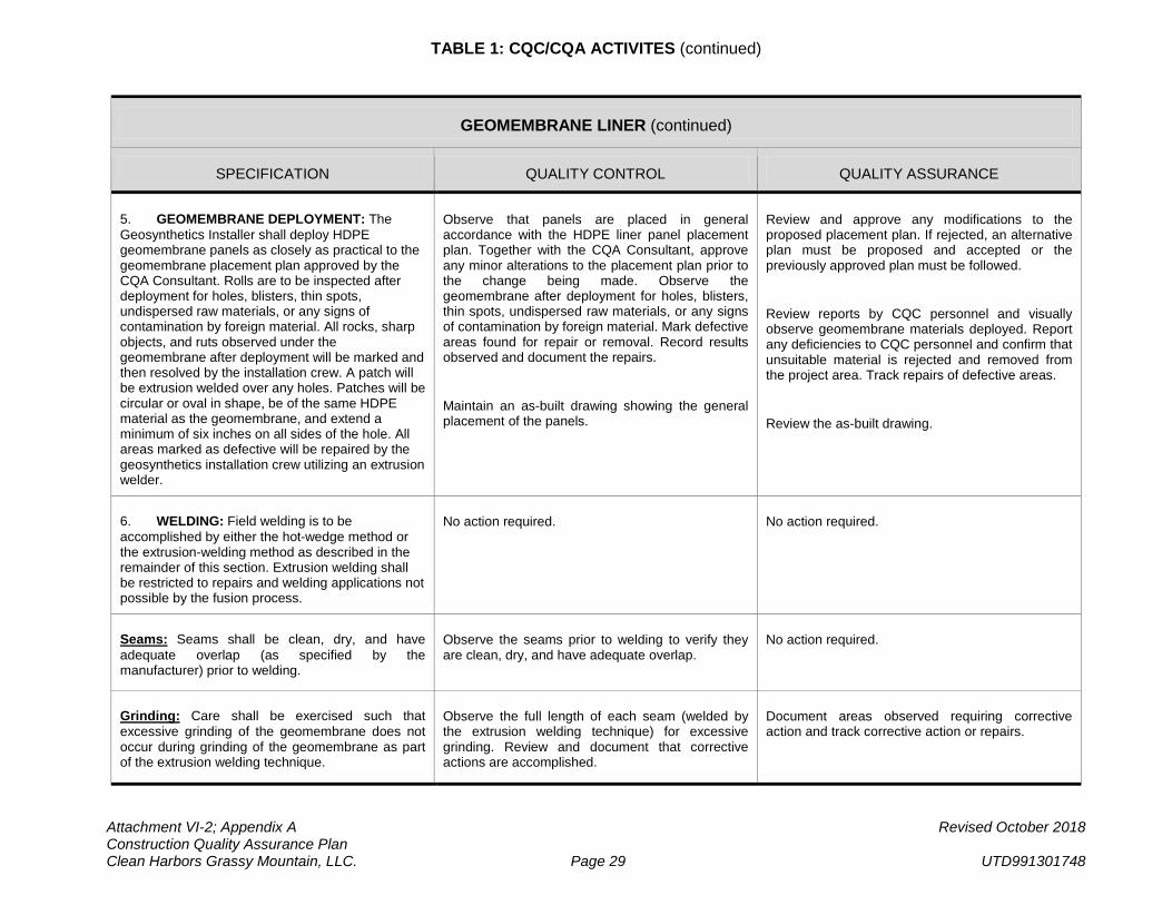
TABLE 1: CQC/CQA ACTIVITES (continued)
Attachment VI-2; Appendix A Revised October 2018 Construction Quality Assurance Plan Clean Harbors Grassy Mountain, LLC. Page 29 UTD991301748
GEOMEMBRANE LINER (continued)
SPECIFICATION QUALITY CONTROL QUALITY ASSURANCE
5. GEOMEMBRANE DEPLOYMENT: The Geosynthetics Installer shall deploy HDPE geomembrane panels as closely as practical to the geomembrane placement plan approved by the CQA Consultant. Rolls are to be inspected after deployment for holes, blisters, thin spots, undispersed raw materials, or any signs of contamination by foreign material. All rocks, sharp objects, and ruts observed under the geomembrane after deployment will be marked and then resolved by the installation crew. A patch will be extrusion welded over any holes. Patches will be circular or oval in shape, be of the same HDPE material as the geomembrane, and extend a minimum of six inches on all sides of the hole. All areas marked as defective will be repaired by the geosynthetics installation crew utilizing an extrusion welder.
Observe that panels are placed in general accordance with the HDPE liner panel placement plan. Together with the CQA Consultant, approve any minor alterations to the placement plan prior to the change being made. Observe the geomembrane after deployment for holes, blisters, thin spots, undispersed raw materials, or any signs of contamination by foreign material. Mark defective areas found for repair or removal. Record results observed and document the repairs.
Maintain an as-built drawing showing the general placement of the panels.
Review and approve any modifications to the proposed placement plan. If rejected, an alternative plan must be proposed and accepted or the previously approved plan must be followed.
Review reports by CQC personnel and visually observe geomembrane materials deployed. Report any deficiencies to CQC personnel and confirm that unsuitable material is rejected and removed from the project area. Track repairs of defective areas.
Review the as-built drawing.
6. WELDING: Field welding is to be accomplished by either the hot-wedge method or the extrusion-welding method as described in the remainder of this section. Extrusion welding shall be restricted to repairs and welding applications not possible by the fusion process.
No action required. No action required.
Seams: Seams shall be clean, dry, and have adequate overlap (as specified by the manufacturer) prior to welding.
Observe the seams prior to welding to verify they are clean, dry, and have adequate overlap.
No action required.
Grinding: Care shall be exercised such that excessive grinding of the geomembrane does not occur during grinding of the geomembrane as part of the extrusion welding technique.
Observe the full length of each seam (welded by the extrusion welding technique) for excessive grinding. Review and document that corrective actions are accomplished.
Document areas observed requiring corrective action and track corrective action or repairs.
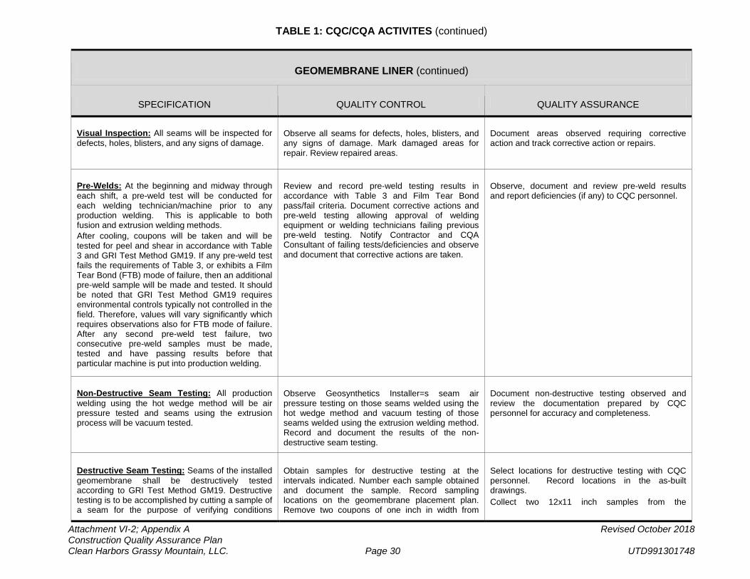
TABLE 1: CQC/CQA ACTIVITES (continued)
Attachment VI-2; Appendix A Revised October 2018 Construction Quality Assurance Plan Clean Harbors Grassy Mountain, LLC. Page 30 UTD991301748
GEOMEMBRANE LINER (continued)
SPECIFICATION QUALITY CONTROL QUALITY ASSURANCE
Visual Inspection: All seams will be inspected for defects, holes, blisters, and any signs of damage.
Observe all seams for defects, holes, blisters, and any signs of damage. Mark damaged areas for repair. Review repaired areas.
Document areas observed requiring corrective action and track corrective action or repairs.
Pre-Welds: At the beginning and midway through each shift, a pre-weld test will be conducted for each welding technician/machine prior to any production welding. This is applicable to both fusion and extrusion welding methods. After cooling, coupons will be taken and will be tested for peel and shear in accordance with Table 3 and GRI Test Method GM19. If any pre-weld test fails the requirements of Table 3, or exhibits a Film Tear Bond (FTB) mode of failure, then an additional pre-weld sample will be made and tested. It should be noted that GRI Test Method GM19 requires environmental controls typically not controlled in the field. Therefore, values will vary significantly which requires observations also for FTB mode of failure. After any second pre-weld test failure, two consecutive pre-weld samples must be made, tested and have passing results before that particular machine is put into production welding.
Review and record pre-weld testing results in accordance with Table 3 and Film Tear Bond pass/fail criteria. Document corrective actions and pre-weld testing allowing approval of welding equipment or welding technicians failing previous pre-weld testing. Notify Contractor and CQA Consultant of failing tests/deficiencies and observe and document that corrective actions are taken.
Observe, document and review pre-weld results and report deficiencies (if any) to CQC personnel.
Non-Destructive Seam Testing: All production welding using the hot wedge method will be air pressure tested and seams using the extrusion process will be vacuum tested.
Observe Geosynthetics Installer=s seam air pressure testing on those seams welded using the hot wedge method and vacuum testing of those seams welded using the extrusion welding method. Record and document the results of the non-destructive seam testing.
Document non-destructive testing observed and review the documentation prepared by CQC personnel for accuracy and completeness.
Destructive Seam Testing: Seams of the installed geomembrane shall be destructively tested according to GRI Test Method GM19. Destructive testing is to be accomplished by cutting a sample of a seam for the purpose of verifying conditions
Obtain samples for destructive testing at the intervals indicated. Number each sample obtained and document the sample. Record sampling locations on the geomembrane placement plan. Remove two coupons of one inch in width from
Select locations for destructive testing with CQC personnel. Record locations in the as-built drawings. Collect two 12x11 inch samples from the
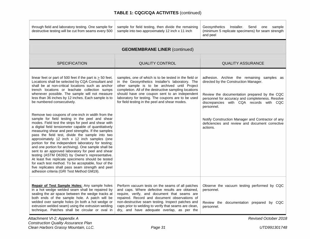
TABLE 1: CQC/CQA ACTIVITES (continued)
Attachment VI-2; Appendix A Revised October 2018 Construction Quality Assurance Plan Clean Harbors Grassy Mountain, LLC. Page 31 UTD991301748
through field and laboratory testing. One sample for destructive testing will be cut from seams every 500
sample for field testing, then divide the remaining sample into two approximately 12 inch x 11 inch
Geosynthetics Installer. Send one sample (minimum 5 replicate specimens) for seam strength and peel
GEOMEMBRANE LINER (continued)
SPECIFICATION QUALITY CONTROL QUALITY ASSURANCE
linear feet or part of 500 feet if the part is > 50 feet. Locations shall be selected by CQA Consultant and shall be at non-critical locations such as anchor trench locations or leachate collection sumps whenever possible. The sample will not measure less than 36 inches by 12 inches. Each sample is to be numbered consecutively.
Remove two coupons of one-inch in width from the sample for field testing in the peel and shear modes. Field test the strips for peel and shear with a digital field tensiometer capable of quantitatively measuring shear and peel strengths. If the samples pass the field test, divide the sample into two approximately 12 inch x 12 inch samples (one portion for the independent laboratory for testing; and one portion for archiving). One sample shall be sent to an approved laboratory for peel and shear testing (ASTM D6392) by Owner’s representative. At least five replicate specimens should be tested for each test method. To be acceptable, four of the five replicates shall pass seam strength and peel adhesion criteria (GRI Test Method GM19).
samples, one of which is to be tested in the field or in the Geosynthetics Installer's laboratory. The other sample is to be archived until Project completion. All of the destructive sampling locations should have one coupon sent to an independent laboratory for testing. The coupons are to be used for field testing in the peel and shear modes.
adhesion. Archive the remaining samples as directed by the Construction Manager.
Review the documentation prepared by the CQC personnel for accuracy and completeness. Resolve discrepancies with CQA records with CQC personnel.
Notify Construction Manager and Contractor of any deficiencies and review and document corrective actions.
Repair of Test Sample Holes: Any sample holes in a hot wedge welded seam shall be repaired by sealing the air space between the wedge tracks at both ends of the sample hole. A patch will be welded over sample holes (in both a hot wedge or extrusion welded seam) using the extrusion welding technique. Patches shall be circular or oval in
Perform vacuum tests on the seams of all patches and caps. Where defective results are obtained, require, verify, and document that seams are repaired. Record and document observations of non-destructive seam testing. Inspect patches and caps prior to welding to verify that seams are clean, dry, and have adequate overlap, as per the
Observe the vacuum testing performed by CQC personnel.
Review the documentation prepared by CQC personnel.
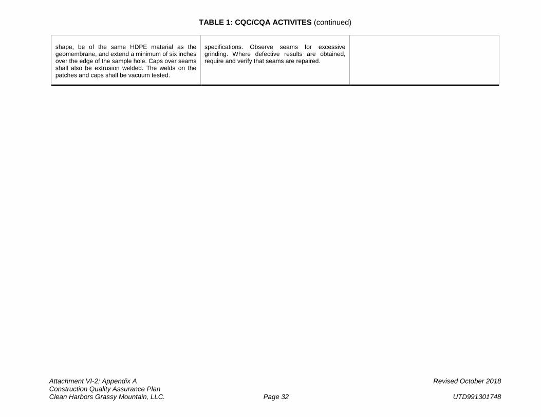
TABLE 1: CQC/CQA ACTIVITES (continued)
Attachment VI-2; Appendix A Revised October 2018 Construction Quality Assurance Plan Clean Harbors Grassy Mountain, LLC. Page 32 UTD991301748
shape, be of the same HDPE material as the geomembrane, and extend a minimum of six inches over the edge of the sample hole. Caps over seams shall also be extrusion welded. The welds on the patches and caps shall be vacuum tested.
specifications. Observe seams for excessive grinding. Where defective results are obtained, require and verify that seams are repaired.
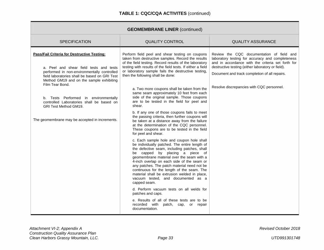
TABLE 1: CQC/CQA ACTIVITES (continued)
Attachment VI-2; Appendix A Revised October 2018 Construction Quality Assurance Plan Clean Harbors Grassy Mountain, LLC. Page 33 UTD991301748
GEOMEMBRANE LINER (continued)
SPECIFICATION QUALITY CONTROL QUALITY ASSURANCE
Pass/Fail Criteria for Destructive Testing:
a. Peel and shear field tests and tests performed in non-environmentally controlled field laboratories shall be based on GRI Test Method GM19 and on the sample exhibiting Film Tear Bond.
b. Tests Performed in environmentally controlled Laboratories shall be based on GRI Test Method GM19.
The geomembrane may be accepted in increments.
Perform field peel and shear testing on coupons taken from destructive samples. Record the results of the field testing. Record results of the laboratory testing with results of the field tests. If either a field or laboratory sample fails the destructive testing, then the following shall be done:
a. Two more coupons shall be taken from the same seam approximately 10 feet from each side of the original sample. Those coupons are to be tested in the field for peel and shear.
b. If any one of those coupons fails to meet the passing criteria, then further coupons will be taken at a distance away from the failure at the determination of the CQC personnel. These coupons are to be tested in the field for peel and shear.
c. Each sample hole and coupon hole shall be individually patched. The entire length of the defective seam, including patches, shall be capped by placing a piece of geomembrane material over the seam with a 4-inch overlap on each side of the seam or any patches. The patch material need not be continuous for the length of the seam. The material shall be extrusion welded in place, vacuum tested, and documented as a capped seam.
d. Perform vacuum tests on all welds for patches and caps.
e. Results of all of these tests are to be recorded with patch, cap, or repair documentation.
Review the CQC documentation of field and laboratory testing for accuracy and completeness and in accordance with the criteria set forth for destructive testing (either laboratory or field).
Document and track completion of all repairs.
Resolve discrepancies with CQC personnel.
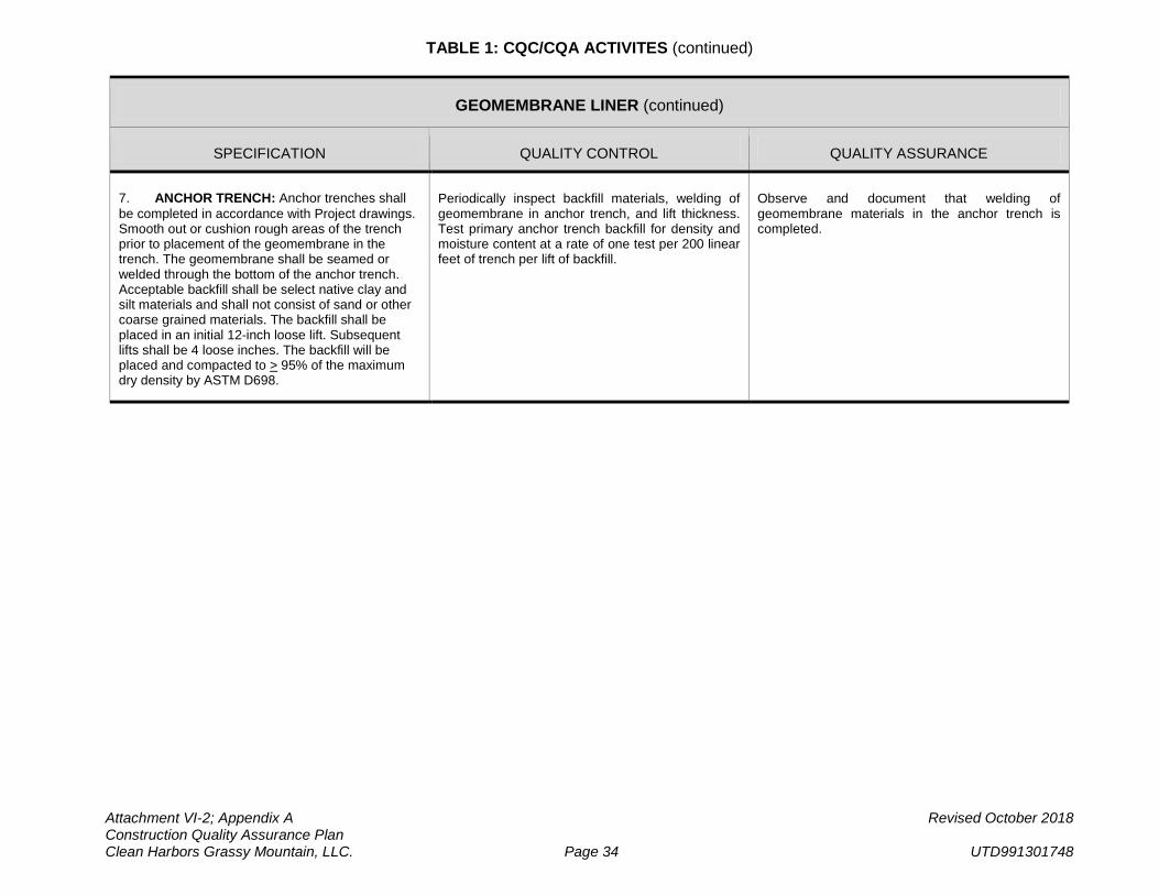
TABLE 1: CQC/CQA ACTIVITES (continued)
Attachment VI-2; Appendix A Revised October 2018 Construction Quality Assurance Plan Clean Harbors Grassy Mountain, LLC. Page 34 UTD991301748
GEOMEMBRANE LINER (continued)
SPECIFICATION QUALITY CONTROL QUALITY ASSURANCE
7. ANCHOR TRENCH: Anchor trenches shall be completed in accordance with Project drawings. Smooth out or cushion rough areas of the trench prior to placement of the geomembrane in the trench. The geomembrane shall be seamed or welded through the bottom of the anchor trench. Acceptable backfill shall be select native clay and silt materials and shall not consist of sand or other coarse grained materials. The backfill shall be placed in an initial 12-inch loose lift. Subsequent lifts shall be 4 loose inches. The backfill will be placed and compacted to > 95% of the maximum dry density by ASTM D698.
Periodically inspect backfill materials, welding of geomembrane in anchor trench, and lift thickness. Test primary anchor trench backfill for density and moisture content at a rate of one test per 200 linear feet of trench per lift of backfill.
Observe and document that welding of geomembrane materials in the anchor trench is completed.
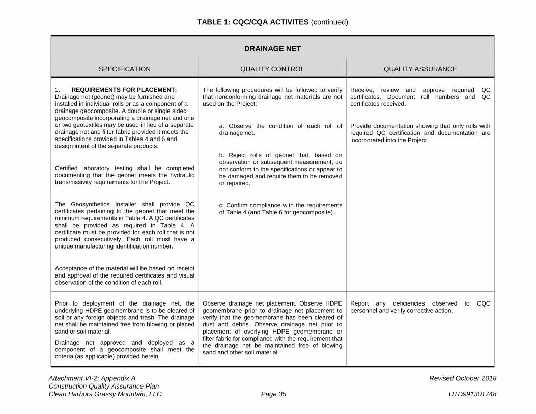
TABLE 1: CQC/CQA ACTIVITES (continued)
Attachment VI-2; Appendix A Revised October 2018 Construction Quality Assurance Plan Clean Harbors Grassy Mountain, LLC. Page 35 UTD991301748
DRAINAGE NET
SPECIFICATION QUALITY CONTROL QUALITY ASSURANCE
1. REQUIREMENTS FOR PLACEMENT: Drainage net (geonet) may be furnished and installed in individual rolls or as a component of a drainage geocomposite. A double or single sided geocomposite incorporating a drainage net and one or two geotextiles may be used in lieu of a separate drainage net and filter fabric provided it meets the specifications provided in Tables 4 and 6 and design intent of the separate products.
Certified laboratory testing shall be completed documenting that the geonet meets the hydraulic transmissivity requirements for the Project.
The Geosynthetics Installer shall provide QC certificates pertaining to the geonet that meet the minimum requirements in Table 4. A QC certificates shall be provided as required in Table 4. A certificate must be provided for each roll that is not produced consecutively. Each roll must have a unique manufacturing identification number.
Acceptance of the material will be based on receipt and approval of the required certificates and visual observation of the condition of each roll.
The following procedures will be followed to verify that nonconforming drainage net materials are not used on the Project:
a. Observe the condition of each roll of drainage net.
b. Reject rolls of geonet that, based on observation or subsequent measurement, do not conform to the specifications or appear to be damaged and require them to be removed or repaired.
c. Confirm compliance with the requirements of Table 4 (and Table 6 for geocomposite).
Receive, review and approve required QC certificates. Document roll numbers and QC certificates received.
Provide documentation showing that only rolls with required QC certification and documentation are incorporated into the Project.
Prior to deployment of the drainage net, the underlying HDPE geomembrane is to be cleared of soil or any foreign objects and trash. The drainage net shall be maintained free from blowing or placed sand or soil material.
Drainage net approved and deployed as a component of a geocomposite shall meet the criteria (as applicable) provided herein.
Observe drainage net placement. Observe HDPE geomembrane prior to drainage net placement to verify that the geomembrane has been cleared of dust and debris. Observe drainage net prior to placement of overlying HDPE geomembrane or filter fabric for compliance with the requirement that the drainage net be maintained free of blowing sand and other soil material.
Report any deficiencies observed to CQC personnel and verify corrective action.
TABLE 1: CQC/CQA ACTIVITES (continued)
Attachment VI-2; Appendix A Revised October 2018 Construction Quality Assurance Plan Clean Harbors Grassy Mountain, LLC. Page 36 UTD991301748
GEOTEXTILE FILTER FABRIC
SPECIFICATION QUALITY CONTROL QUALITY ASSURANCE
1. MATERIALS: Geotextile filter fabric may be furnished as individual rolls or as a component of a drainage geocomposite.
Geotextile shall not be used on the Project until QC certificates have been provided and the geotextile has been accepted by CQC personnel. Material shall meet minimum requirements in Table 6. Acceptance of the material will be based on visual observation of the condition, QC certifications and verification of the proper weight of each roll.
The following procedures will be followed to verify that nonconforming filter fabric materials are not used on the Project:
a. Observe the condition of each roll of filter fabric and observe that the tag or printing on each roll indicates that the roll is the type that has been specified.
b. Mark rolls of fabric that, based on observation, do not conform to the specifications or appear to be damaged, and require them to be removed or repaired.
Report any deficiencies observed to CQC personnel and verify corrective action. Confirm that rejects rolls/material is removed from the project area.
2. INSTALLATION: The filter fabric shall be installed to prevent damage to the surface of the landfill, the geomembrane liners and the drainage net. The rolls of geotextile filter fabric shall be overlapped and joined to meet manufacturer=s recommendations. The fabric shall be placed such that the upslope fabric will overlap the downslope fabric, if possible.
Observe the filter fabric placement. Observe placement and joining of adjacent rolls of fabric for compliance. Require deficiencies to be corrected prior to covering the fabric.
Report any deficiencies observed to CQC personnel and verify corrective action.
3. GETEXTILE AS PART OF A GEOCOMPOSITE: Geotextile filter fabric approved and deployed as a component of a drainage geocomposite shall meet the criteria for materials (Tables 4 and 6) and installation (as applicable) provided herein.
No action required. No action required.
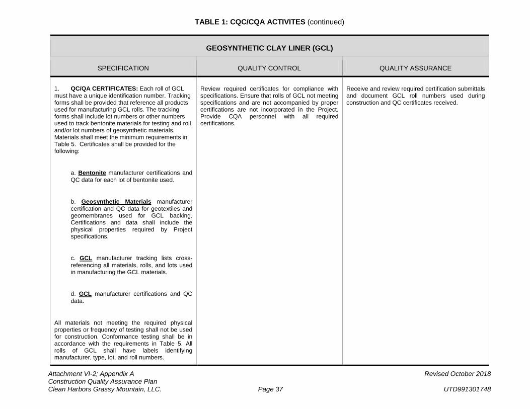
TABLE 1: CQC/CQA ACTIVITES (continued)
Attachment VI-2; Appendix A Revised October 2018 Construction Quality Assurance Plan Clean Harbors Grassy Mountain, LLC. Page 37 UTD991301748
GEOSYNTHETIC CLAY LINER (GCL)
SPECIFICATION QUALITY CONTROL QUALITY ASSURANCE
1. QC/QA CERTIFICATES: Each roll of GCL must have a unique identification number. Tracking forms shall be provided that reference all products used for manufacturing GCL rolls. The tracking forms shall include lot numbers or other numbers used to track bentonite materials for testing and roll and/or lot numbers of geosynthetic materials. Materials shall meet the minimum requirements in Table 5. Certificates shall be provided for the following:
a. Bentonite manufacturer certifications and QC data for each lot of bentonite used.
b. Geosynthetic Materials manufacturer certification and QC data for geotextiles and geomembranes used for GCL backing. Certifications and data shall include the physical properties required by Project specifications.
c. GCL manufacturer tracking lists cross- referencing all materials, rolls, and lots used in manufacturing the GCL materials.
d. GCL manufacturer certifications and QC data.
All materials not meeting the required physical properties or frequency of testing shall not be used for construction. Conformance testing shall be in accordance with the requirements in Table 5. All rolls of GCL shall have labels identifying manufacturer, type, lot, and roll numbers.
Review required certificates for compliance with specifications. Ensure that rolls of GCL not meeting specifications and are not accompanied by proper certifications are not incorporated in the Project. Provide CQA personnel with all required certifications.
Receive and review required certification submittals and document GCL roll numbers used during construction and QC certificates received.
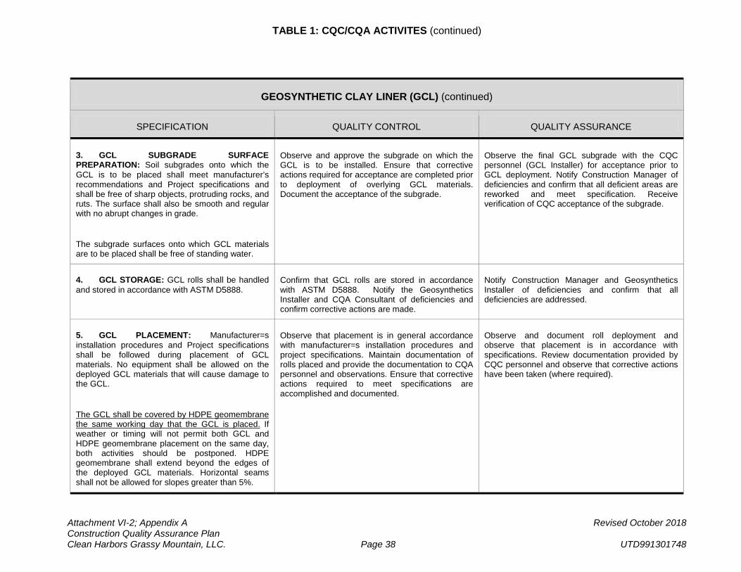
TABLE 1: CQC/CQA ACTIVITES (continued)
Attachment VI-2; Appendix A Revised October 2018 Construction Quality Assurance Plan Clean Harbors Grassy Mountain, LLC. Page 38 UTD991301748
GEOSYNTHETIC CLAY LINER (GCL) (continued)
SPECIFICATION QUALITY CONTROL QUALITY ASSURANCE
3. GCL SUBGRADE SURFACE PREPARATION: Soil subgrades onto which the GCL is to be placed shall meet manufacturer’s recommendations and Project specifications and shall be free of sharp objects, protruding rocks, and ruts. The surface shall also be smooth and regular with no abrupt changes in grade.
The subgrade surfaces onto which GCL materials are to be placed shall be free of standing water.
Observe and approve the subgrade on which the GCL is to be installed. Ensure that corrective actions required for acceptance are completed prior to deployment of overlying GCL materials. Document the acceptance of the subgrade.
Observe the final GCL subgrade with the CQC personnel (GCL Installer) for acceptance prior to GCL deployment. Notify Construction Manager of deficiencies and confirm that all deficient areas are reworked and meet specification. Receive verification of CQC acceptance of the subgrade.
4. GCL STORAGE: GCL rolls shall be handled and stored in accordance with ASTM D5888.
Confirm that GCL rolls are stored in accordance with ASTM D5888. Notify the Geosynthetics Installer and CQA Consultant of deficiencies and confirm corrective actions are made.
Notify Construction Manager and Geosynthetics Installer of deficiencies and confirm that all deficiencies are addressed.
5. GCL PLACEMENT: Manufacturer=s installation procedures and Project specifications shall be followed during placement of GCL materials. No equipment shall be allowed on the deployed GCL materials that will cause damage to the GCL.
The GCL shall be covered by HDPE geomembrane the same working day that the GCL is placed. If weather or timing will not permit both GCL and HDPE geomembrane placement on the same day, both activities should be postponed. HDPE geomembrane shall extend beyond the edges of the deployed GCL materials. Horizontal seams shall not be allowed for slopes greater than 5%.
Observe that placement is in general accordance with manufacturer=s installation procedures and project specifications. Maintain documentation of rolls placed and provide the documentation to CQA personnel and observations. Ensure that corrective actions required to meet specifications are accomplished and documented.
Observe and document roll deployment and observe that placement is in accordance with specifications. Review documentation provided by CQC personnel and observe that corrective actions have been taken (where required).
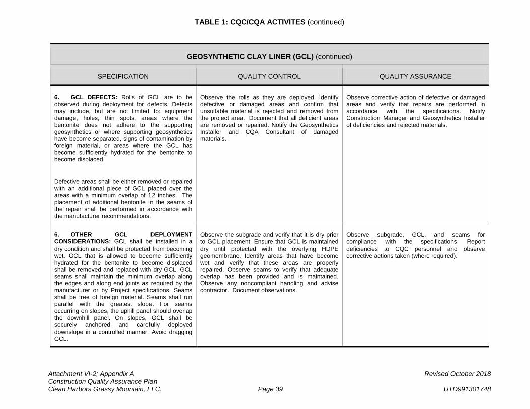
TABLE 1: CQC/CQA ACTIVITES (continued)
Attachment VI-2; Appendix A Revised October 2018 Construction Quality Assurance Plan Clean Harbors Grassy Mountain, LLC. Page 39 UTD991301748
GEOSYNTHETIC CLAY LINER (GCL) (continued)
SPECIFICATION QUALITY CONTROL QUALITY ASSURANCE
6. GCL DEFECTS: Rolls of GCL are to be observed during deployment for defects. Defects may include, but are not limited to: equipment damage, holes, thin spots, areas where the bentonite does not adhere to the supporting geosynthetics or where supporting geosynthetics have become separated, signs of contamination by foreign material, or areas where the GCL has become sufficiently hydrated for the bentonite to become displaced.
Defective areas shall be either removed or repaired with an additional piece of GCL placed over the areas with a minimum overlap of 12 inches. The placement of additional bentonite in the seams of the repair shall be performed in accordance with the manufacturer recommendations.
Observe the rolls as they are deployed. Identify defective or damaged areas and confirm that unsuitable material is rejected and removed from the project area. Document that all deficient areas are removed or repaired. Notify the Geosynthetics Installer and CQA Consultant of damaged materials.
Observe corrective action of defective or damaged areas and verify that repairs are performed in accordance with the specifications. Notify Construction Manager and Geosynthetics Installer of deficiencies and rejected materials.
6. OTHER GCL DEPLOYMENT CONSIDERATIONS: GCL shall be installed in a dry condition and shall be protected from becoming wet. GCL that is allowed to become sufficiently hydrated for the bentonite to become displaced shall be removed and replaced with dry GCL. GCL seams shall maintain the minimum overlap along the edges and along end joints as required by the manufacturer or by Project specifications. Seams shall be free of foreign material. Seams shall run parallel with the greatest slope. For seams occurring on slopes, the uphill panel should overlap the downhill panel. On slopes, GCL shall be securely anchored and carefully deployed downslope in a controlled manner. Avoid dragging GCL.
Observe the subgrade and verify that it is dry prior to GCL placement. Ensure that GCL is maintained dry until protected with the overlying HDPE geomembrane. Identify areas that have become wet and verify that these areas are properly repaired. Observe seams to verify that adequate overlap has been provided and is maintained. Observe any noncompliant handling and advise contractor. Document observations.
Observe subgrade, GCL, and seams for compliance with the specifications. Report deficiencies to CQC personnel and observe corrective actions taken (where required).
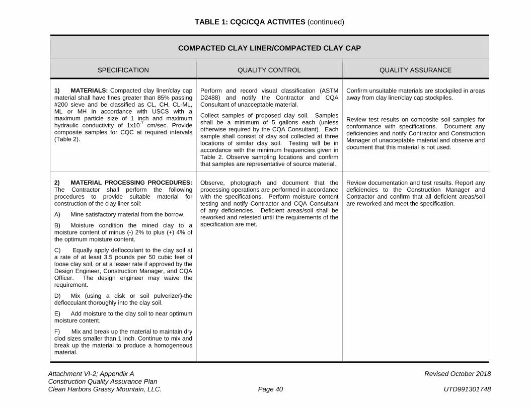
TABLE 1: CQC/CQA ACTIVITES (continued)
Attachment VI-2; Appendix A Revised October 2018 Construction Quality Assurance Plan Clean Harbors Grassy Mountain, LLC. Page 40 UTD991301748
COMPACTED CLAY LINER/COMPACTED CLAY CAP
SPECIFICATION QUALITY CONTROL QUALITY ASSURANCE
1) MATERIALS: Compacted clay liner/clay cap material shall have fines greater than 85% passing #200 sieve and be classified as CL, CH, CL-ML, ML or MH in accordance with USCS with a maximum particle size of 1 inch and maximum hydraulic conductivity of 1x10⁻⁷ cm/sec. Provide composite samples for CQC at required intervals (Table 2).
Perform and record visual classification (ASTM D2488) and notify the Contractor and CQA Consultant of unacceptable material.
Collect samples of proposed clay soil. Samples shall be a minimum of 5 gallons each (unless otherwise required by the CQA Consultant). Each sample shall consist of clay soil collected at three locations of similar clay soil. Testing will be in accordance with the minimum frequencies given in Table 2. Observe sampling locations and confirm that samples are representative of source material.
Confirm unsuitable materials are stockpiled in areas away from clay liner/clay cap stockpiles.
Review test results on composite soil samples for conformance with specifications. Document any deficiencies and notify Contractor and Construction Manager of unacceptable material and observe and document that this material is not used.
2) MATERIAL PROCESSING PROCEDURES: The Contractor shall perform the following procedures to provide suitable material for construction of the clay liner soil:
A) Mine satisfactory material from the borrow.
B) Moisture condition the mined clay to a moisture content of minus (-) 2% to plus (+) 4% of the optimum moisture content.
C) Equally apply deflocculant to the clay soil at a rate of at least 3.5 pounds per 50 cubic feet of loose clay soil, or at a lesser rate if approved by the Design Engineer, Construction Manager, and CQA Officer. The design engineer may waive the requirement.
D) Mix (using a disk or soil pulverizer)-the deflocculant thoroughly into the clay soil.
E) Add moisture to the clay soil to near optimum moisture content.
F) Mix and break up the material to maintain dry clod sizes smaller than 1 inch. Continue to mix and break up the material to produce a homogeneous material.
Observe, photograph and document that the processing operations are performed in accordance with the specifications. Perform moisture content testing and notify Contractor and CQA Consultant of any deficiencies. Deficient areas/soil shall be reworked and retested until the requirements of the specification are met.
Review documentation and test results. Report any deficiencies to the Construction Manager and Contractor and confirm that all deficient areas/soil are reworked and meet the specification.
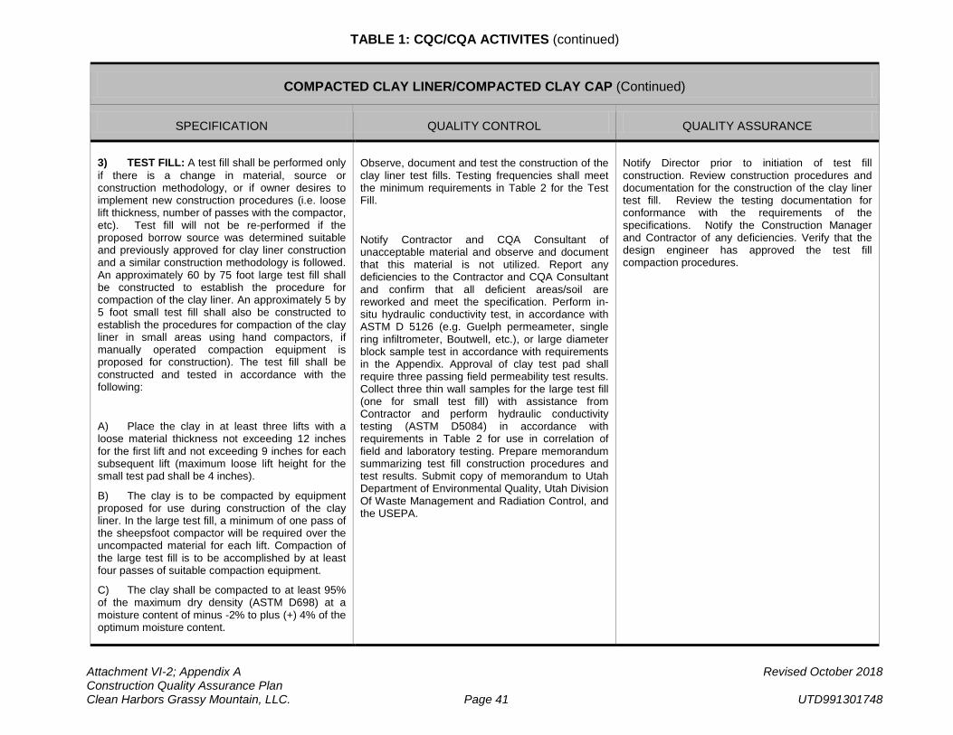
TABLE 1: CQC/CQA ACTIVITES (continued)
Attachment VI-2; Appendix A Revised October 2018 Construction Quality Assurance Plan Clean Harbors Grassy Mountain, LLC. Page 41 UTD991301748
COMPACTED CLAY LINER/COMPACTED CLAY CAP (Continued)
SPECIFICATION QUALITY CONTROL QUALITY ASSURANCE
3) TEST FILL: A test fill shall be performed only if there is a change in material, source or construction methodology, or if owner desires to implement new construction procedures (i.e. loose lift thickness, number of passes with the compactor, etc). Test fill will not be re-performed if the proposed borrow source was determined suitable and previously approved for clay liner construction and a similar construction methodology is followed. An approximately 60 by 75 foot large test fill shall be constructed to establish the procedure for compaction of the clay liner. An approximately 5 by 5 foot small test fill shall also be constructed to establish the procedures for compaction of the clay liner in small areas using hand compactors, if manually operated compaction equipment is proposed for construction). The test fill shall be constructed and tested in accordance with the following:
A) Place the clay in at least three lifts with a loose material thickness not exceeding 12 inches for the first lift and not exceeding 9 inches for each subsequent lift (maximum loose lift height for the small test pad shall be 4 inches).
B) The clay is to be compacted by equipment proposed for use during construction of the clay liner. In the large test fill, a minimum of one pass of the sheepsfoot compactor will be required over the uncompacted material for each lift. Compaction of the large test fill is to be accomplished by at least four passes of suitable compaction equipment.
C) The clay shall be compacted to at least 95% of the maximum dry density (ASTM D698) at a moisture content of minus -2% to plus (+) 4% of the optimum moisture content.
Observe, document and test the construction of the clay liner test fills. Testing frequencies shall meet the minimum requirements in Table 2 for the Test Fill.
Notify Contractor and CQA Consultant of unacceptable material and observe and document that this material is not utilized. Report any deficiencies to the Contractor and CQA Consultant and confirm that all deficient areas/soil are reworked and meet the specification. Perform in-situ hydraulic conductivity test, in accordance with ASTM D 5126 (e.g. Guelph permeameter, single ring infiltrometer, Boutwell, etc.), or large diameter block sample test in accordance with requirements in the Appendix. Approval of clay test pad shall require three passing field permeability test results. Collect three thin wall samples for the large test fill (one for small test fill) with assistance from Contractor and perform hydraulic conductivity testing (ASTM D5084) in accordance with requirements in Table 2 for use in correlation of field and laboratory testing. Prepare memorandum summarizing test fill construction procedures and test results. Submit copy of memorandum to Utah Department of Environmental Quality, Utah Division Of Waste Management and Radiation Control, and the USEPA.
Notify Director prior to initiation of test fill construction. Review construction procedures and documentation for the construction of the clay liner test fill. Review the testing documentation for conformance with the requirements of the specifications. Notify the Construction Manager and Contractor of any deficiencies. Verify that the design engineer has approved the test fill compaction procedures.
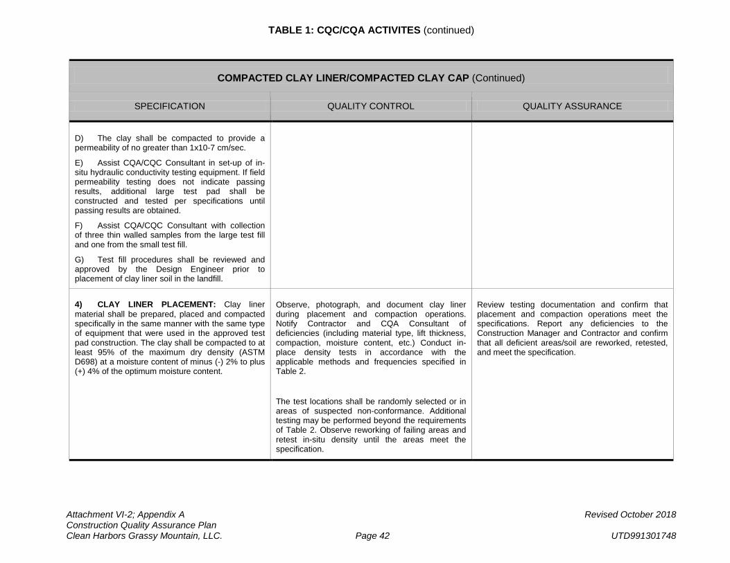
TABLE 1: CQC/CQA ACTIVITES (continued)
Attachment VI-2; Appendix A Revised October 2018 Construction Quality Assurance Plan Clean Harbors Grassy Mountain, LLC. Page 42 UTD991301748
COMPACTED CLAY LINER/COMPACTED CLAY CAP (Continued)
SPECIFICATION QUALITY CONTROL QUALITY ASSURANCE
D) The clay shall be compacted to provide a permeability of no greater than 1x10⁻⁷ cm/sec.
E) Assist CQA/CQC Consultant in set-up of in-situ hydraulic conductivity testing equipment. If field permeability testing does not indicate passing results, additional large test pad shall be constructed and tested per specifications until passing results are obtained.
F) Assist CQA/CQC Consultant with collection of three thin walled samples from the large test fill and one from the small test fill.
G) Test fill procedures shall be reviewed and approved by the Design Engineer prior to placement of clay liner soil in the landfill.
4) CLAY LINER PLACEMENT: Clay liner material shall be prepared, placed and compacted specifically in the same manner with the same type of equipment that were used in the approved test pad construction. The clay shall be compacted to at least 95% of the maximum dry density (ASTM D698) at a moisture content of minus (-) 2% to plus (+) 4% of the optimum moisture content.
Observe, photograph, and document clay liner during placement and compaction operations. Notify Contractor and CQA Consultant of deficiencies (including material type, lift thickness, compaction, moisture content, etc.) Conduct in-place density tests in accordance with the applicable methods and frequencies specified in Table 2.
The test locations shall be randomly selected or in areas of suspected non-conformance. Additional testing may be performed beyond the requirements of Table 2. Observe reworking of failing areas and retest in-situ density until the areas meet the specification.
Review testing documentation and confirm that placement and compaction operations meet the specifications. Report any deficiencies to the Construction Manager and Contractor and confirm that all deficient areas/soil are reworked, retested, and meet the specification.
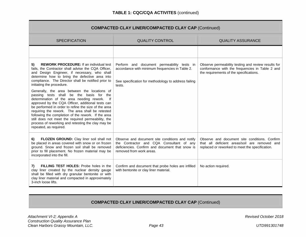
TABLE 1: CQC/CQA ACTIVITES (continued)
Attachment VI-2; Appendix A Revised October 2018 Construction Quality Assurance Plan Clean Harbors Grassy Mountain, LLC. Page 43 UTD991301748
COMPACTED CLAY LINER/COMPACTED CLAY CAP (Continued)
SPECIFICATION QUALITY CONTROL QUALITY ASSURANCE
5) REWORK PROCEDURE: If an individual test fails, the Contractor shall advise the CQA Officer, and Design Engineer, if necessary, who shall determine how to bring the defective area into compliance. The Director shall be notified prior to initiating the procedure.
Generally, the area between the locations of passing tests shall be the basis for the determination of the area needing rework. If approved by the CQA Officer, additional tests can be performed in order to refine the size of the area requiring the rework. The area shall be retested following the completion of the rework. If the area still does not meet the required permeability, the process of reworking and retesting the clay may be repeated, as required.
Perform and document permeability tests in accordance with minimum frequencies in Table 2.
See specification for methodology to address failing tests.
Observe permeability testing and review results for conformance with the frequencies in Table 2 and the requirements of the specifications.
6) FLOZEN GROUND: Clay liner soil shall not be placed in areas covered with snow or on frozen ground. Snow and frozen soil shall be removed prior to fill placement. No frozen material may be incorporated into the fill.
Observe and document site conditions and notify the Contractor and CQA Consultant of any deficiencies. Confirm and document that snow is removed from work areas.
Observe and document site conditions. Confirm that all deficient areas/soil are removed and replaced or reworked to meet the specification.
7) FILLING TEST HOLES: Probe holes in the clay liner created by the nuclear density gauge shall be filled with dry granular bentonite or with clay liner material and compacted in approximately 3-inch loose lifts.
Confirm and document that probe holes are infilled with bentonite or clay liner material.
No action required.
COMPACTED CLAY LINER/COMPACTED CLAY CAP (Continued)
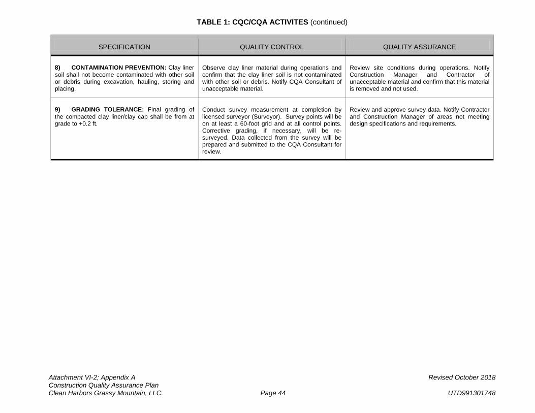
TABLE 1: CQC/CQA ACTIVITES (continued)
Attachment VI-2; Appendix A Revised October 2018 Construction Quality Assurance Plan Clean Harbors Grassy Mountain, LLC. Page 44 UTD991301748
SPECIFICATION QUALITY CONTROL QUALITY ASSURANCE
8) CONTAMINATION PREVENTION: Clay liner soil shall not become contaminated with other soil or debris during excavation, hauling, storing and placing.
Observe clay liner material during operations and confirm that the clay liner soil is not contaminated with other soil or debris. Notify CQA Consultant of unacceptable material.
Review site conditions during operations. Notify Construction Manager and Contractor of unacceptable material and confirm that this material is removed and not used.
9) GRADING TOLERANCE: Final grading of the compacted clay liner/clay cap shall be from at grade to +0.2 ft.
Conduct survey measurement at completion by licensed surveyor (Surveyor). Survey points will be on at least a 60-foot grid and at all control points. Corrective grading, if necessary, will be re-surveyed. Data collected from the survey will be prepared and submitted to the CQA Consultant for review.
Review and approve survey data. Notify Contractor and Construction Manager of areas not meeting design specifications and requirements.
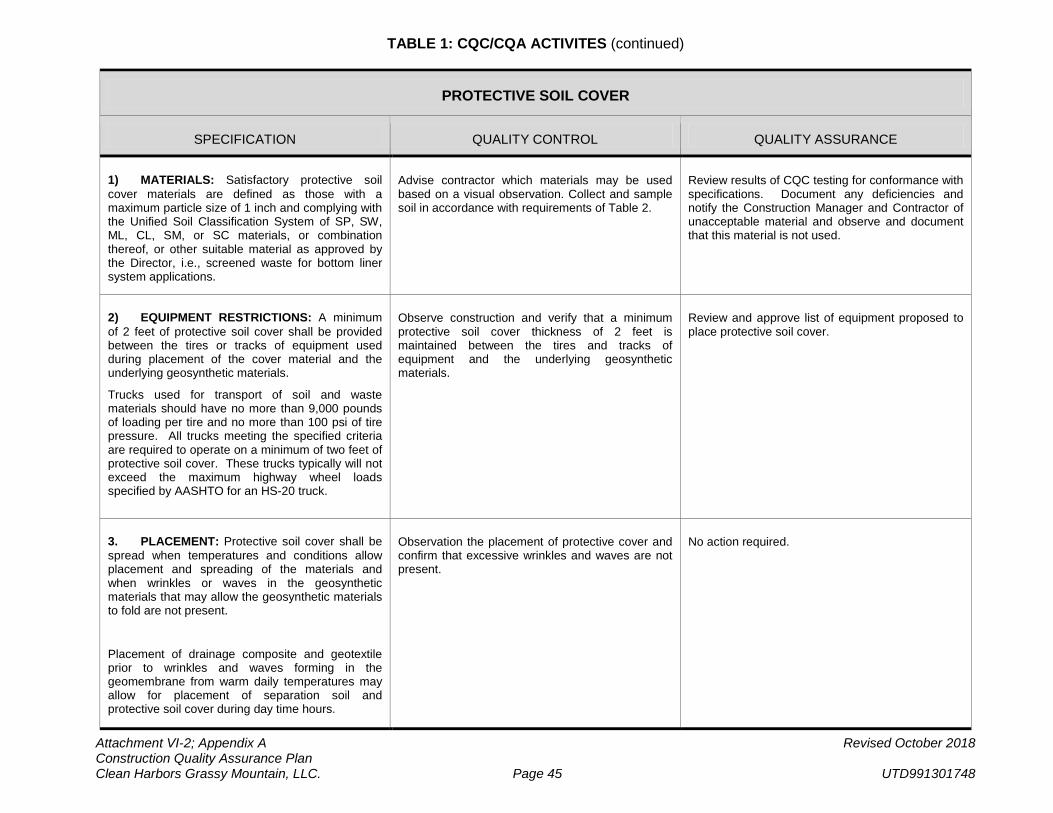
TABLE 1: CQC/CQA ACTIVITES (continued)
Attachment VI-2; Appendix A Revised October 2018 Construction Quality Assurance Plan Clean Harbors Grassy Mountain, LLC. Page 45 UTD991301748
PROTECTIVE SOIL COVER
SPECIFICATION QUALITY CONTROL QUALITY ASSURANCE
1) MATERIALS: Satisfactory protective soil cover materials are defined as those with a maximum particle size of 1 inch and complying with the Unified Soil Classification System of SP, SW, ML, CL, SM, or SC materials, or combination thereof, or other suitable material as approved by the Director, i.e., screened waste for bottom liner system applications.
Advise contractor which materials may be used based on a visual observation. Collect and sample soil in accordance with requirements of Table 2.
Review results of CQC testing for conformance with specifications. Document any deficiencies and notify the Construction Manager and Contractor of unacceptable material and observe and document that this material is not used.
2) EQUIPMENT RESTRICTIONS: A minimum of 2 feet of protective soil cover shall be provided between the tires or tracks of equipment used during placement of the cover material and the underlying geosynthetic materials.
Trucks used for transport of soil and waste materials should have no more than 9,000 pounds of loading per tire and no more than 100 psi of tire pressure. All trucks meeting the specified criteria are required to operate on a minimum of two feet of protective soil cover. These trucks typically will not exceed the maximum highway wheel loads specified by AASHTO for an HS-20 truck.
Observe construction and verify that a minimum protective soil cover thickness of 2 feet is maintained between the tires and tracks of equipment and the underlying geosynthetic materials.
Review and approve list of equipment proposed to place protective soil cover.
3. PLACEMENT: Protective soil cover shall be spread when temperatures and conditions allow placement and spreading of the materials and when wrinkles or waves in the geosynthetic materials that may allow the geosynthetic materials to fold are not present.
Placement of drainage composite and geotextile prior to wrinkles and waves forming in the geomembrane from warm daily temperatures may allow for placement of separation soil and protective soil cover during day time hours.
Observation the placement of protective cover and confirm that excessive wrinkles and waves are not present.
No action required.
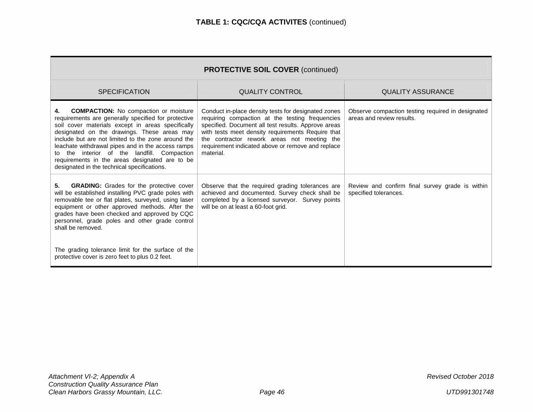
TABLE 1: CQC/CQA ACTIVITES (continued)
Attachment VI-2; Appendix A Revised October 2018 Construction Quality Assurance Plan Clean Harbors Grassy Mountain, LLC. Page 46 UTD991301748
PROTECTIVE SOIL COVER (continued)
SPECIFICATION QUALITY CONTROL QUALITY ASSURANCE
4. COMPACTION: No compaction or moisture requirements are generally specified for protective soil cover materials except in areas specifically designated on the drawings. These areas may include but are not limited to the zone around the leachate withdrawal pipes and in the access ramps to the interior of the landfill. Compaction requirements in the areas designated are to be designated in the technical specifications.
Conduct in-place density tests for designated zones requiring compaction at the testing frequencies specified. Document all test results. Approve areas with tests meet density requirements Require that the contractor rework areas not meeting the requirement indicated above or remove and replace material.
Observe compaction testing required in designated areas and review results.
5. GRADING: Grades for the protective cover will be established installing PVC grade poles with removable tee or flat plates, surveyed, using laser equipment or other approved methods. After the grades have been checked and approved by CQC personnel, grade poles and other grade control shall be removed.
The grading tolerance limit for the surface of the protective cover is zero feet to plus 0.2 feet.
Observe that the required grading tolerances are achieved and documented. Survey check shall be completed by a licensed surveyor. Survey points will be on at least a 60-foot grid.
Review and confirm final survey grade is within specified tolerances.
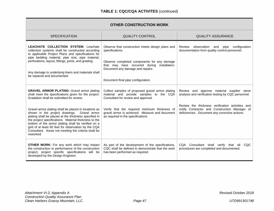
TABLE 1: CQC/CQA ACTIVITES (continued)
Attachment VI-2; Appendix A Revised October 2018 Construction Quality Assurance Plan Clean Harbors Grassy Mountain, LLC. Page 47 UTD991301748
OTHER CONSTRUCTION WORK
SPECIFICATION QUALITY CONTROL QUALITY ASSURANCE
LEACHATE COLLECTION SYSTEM: Leachate collection systems shall be constructed according to applicable Project Plans and specifications for pipe bedding material, pipe size, pipe material, perforations, layout, fittings, joints, and grading.
Any damage to underlying liners and materials shall be repaired and documented.
Observe that construction meets design plans and specifications.
Observe completed components for any damage that may have occurred during installation. Document any damage and repairs.
Document final pipe configuration.
Review observation and pipe configuration documentation from quality control personnel.
GRAVEL ARMOR PLATING: Gravel armor plating shall meet the specifications given for the project. Gradation shall be submitted for review.
Gravel armor plating shall be placed in locations as shown in the project drawings. Gravel armor plating shall be placed at the thickness specified in the project specifications. Material thickness to the bottom of the armor plating shall be verified on a grid of at least 60 feet for observation by the CQA Consultant. Areas not meeting the criteria shall be reworked.
Collect samples of proposed gravel armor plating material and provide samples to the CQA Consultant for review and approval.
Verify that the required minimum thickness of gravel armor is achieved. Measure and document as required in the specifications.
Review and approve material supplier sieve analysis and verification testing by CQC personnel.
Review the thickness verification activities and notify Contractor and Construction Manager of deficiencies. Document any corrective actions.
OTHER WORK: For any work which may impact the construction or performance of the construction project, project specific specifications will be developed by the Design Engineer.
As part of the development of the specifications, CQC shall be defined to demonstrate that the work has been performed as required.
CQA Consultant shall verify that all CQC procedures are completed and documented.
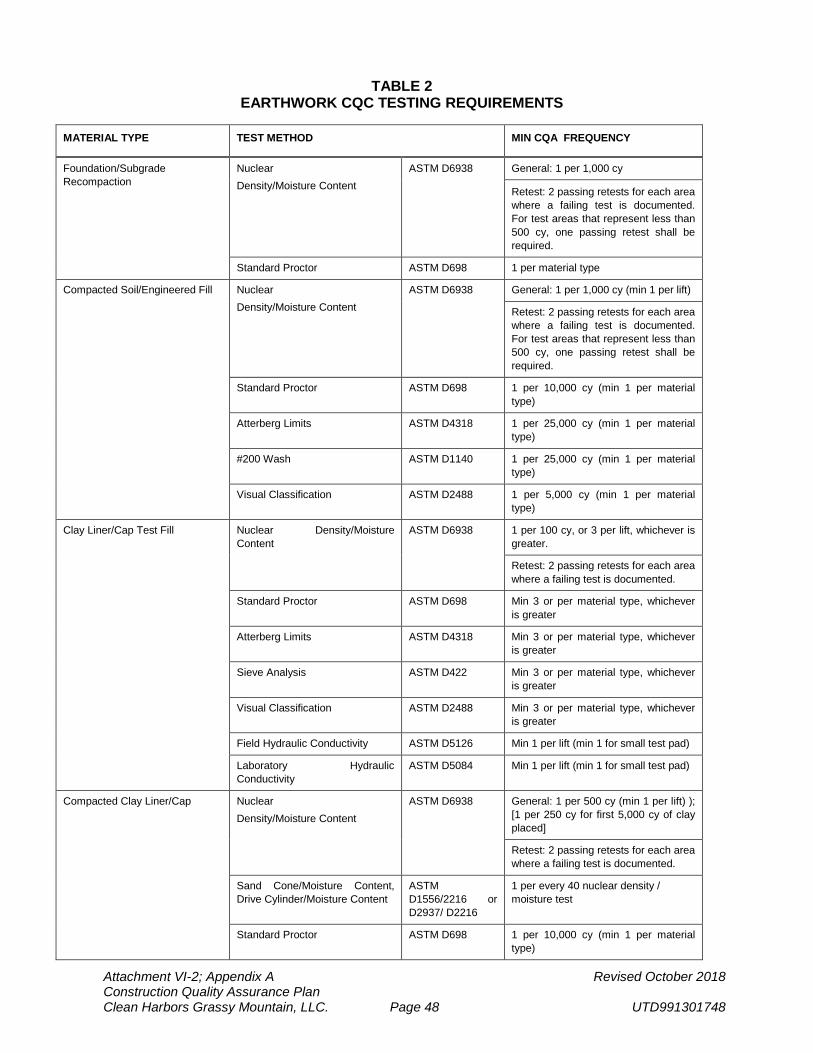
Attachment VI-2; Appendix A Revised October 2018 Construction Quality Assurance Plan Clean Harbors Grassy Mountain, LLC. Page 48 UTD991301748
TABLE 2 EARTHWORK CQC TESTING REQUIREMENTS
MATERIAL TYPE TEST METHOD MIN CQA FREQUENCY
Foundation/Subgrade Recompaction
Nuclear Density/Moisture Content
ASTM D6938 General: 1 per 1,000 cy
Retest: 2 passing retests for each area where a failing test is documented. For test areas that represent less than 500 cy, one passing retest shall be required.
Standard Proctor ASTM D698 1 per material type
Compacted Soil/Engineered Fill Nuclear Density/Moisture Content
ASTM D6938 General: 1 per 1,000 cy (min 1 per lift)
Retest: 2 passing retests for each area where a failing test is documented. For test areas that represent less than 500 cy, one passing retest shall be required.
Standard Proctor ASTM D698 1 per 10,000 cy (min 1 per material type)
Atterberg Limits ASTM D4318 1 per 25,000 cy (min 1 per material type)
#200 Wash ASTM D1140 1 per 25,000 cy (min 1 per material type)
Visual Classification ASTM D2488 1 per 5,000 cy (min 1 per material type)
Clay Liner/Cap Test Fill Nuclear Density/Moisture Content
ASTM D6938 1 per 100 cy, or 3 per lift, whichever is greater.
Retest: 2 passing retests for each area where a failing test is documented.
Standard Proctor ASTM D698 Min 3 or per material type, whichever is greater
Atterberg Limits ASTM D4318 Min 3 or per material type, whichever is greater
Sieve Analysis ASTM D422 Min 3 or per material type, whichever is greater
Visual Classification ASTM D2488 Min 3 or per material type, whichever is greater
Field Hydraulic Conductivity ASTM D5126 Min 1 per lift (min 1 for small test pad)
Laboratory Hydraulic Conductivity
ASTM D5084 Min 1 per lift (min 1 for small test pad)
Compacted Clay Liner/Cap Nuclear Density/Moisture Content
ASTM D6938 General: 1 per 500 cy (min 1 per lift) ); [1 per 250 cy for first 5,000 cy of clay placed]
Retest: 2 passing retests for each area where a failing test is documented.
Sand Cone/Moisture Content, Drive Cylinder/Moisture Content
ASTM D1556/2216 or D2937/ D2216
1 per every 40 nuclear density / moisture test
Standard Proctor ASTM D698 1 per 10,000 cy (min 1 per material type)
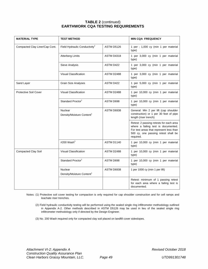
Attachment VI-2; Appendix A Revised October 2018 Construction Quality Assurance Plan Clean Harbors Grassy Mountain, LLC. Page 49 UTD991301748
TABLE 2 (continued) EARTHWORK CQA TESTING REQUIREMENTS
MATERIAL TYPE TEST METHOD MIN CQA FREQUENCY
Compacted Clay Liner/Cap Cont. Field Hydraulic Conductivity2 ASTM D5126 1 per ; 1,000 cy (min 1 per material type)
Atterberg Limits ASTM D4318 1 per 3,000 cy (min 1 per material type)
Sieve Analysis ASTM D422 1 per 3,000 cy (min 1 per material type)
Visual Classification ASTM D2488 1 per 3,000 cy (min 1 per material type)
Sand Layer Grain Size Analyses ASTM D422 1 per 5,000 cy (min 1 per material type)
Protective Soil Cover Visual Classification ASTM D2488 1 per 10,000 cy (min 1 per material type)
Standard Proctor1 ASTM D698 1 per 10,000 cy (min 1 per material type)
Nuclear Density/Moisture Content1
ASTM D6938 General: Min 2 per lift (cap shoulder construction) or 1 per 30 feet of pipe length (riser trench)
Retest: 2 passing retests for each area where a failing test is documented. For test areas that represent less than 500 cy, one passing retest shall be required.
#200 Wash3 ASTM D1140 1 per 10,000 cy (min 1 per material type)
Compacted Clay Soil Visual Classification ASTM D2488 1 per 10,000 cy (min 1 per material type)
Standard Proctor1 ASTM D698 1 per 10,000 cy (min 1 per material type)
Nuclear Density/Moisture Content1
ASTM D6938 1 per 1000 cy (min 1 per lift)
Retest: minimum of 1 passing retest for each area where a failing test is documented.
Notes: (1) Protective soil cover testing for compaction is only required for cap shoulder construction and for cell ramps and
leachate riser trenches. (2) Field hydraulic conductivity testing will be performed using the sealed single ring infiltrometer methodology outlined
in Appendix A-2. Other methods described in ASTM D5126 may be used in lieu of the sealed single ring infiltrometer methodology only if directed by the Design Engineer.
(3) No. 200 Wash required only for compacted clay soil placed on landfill cover sideslopes.
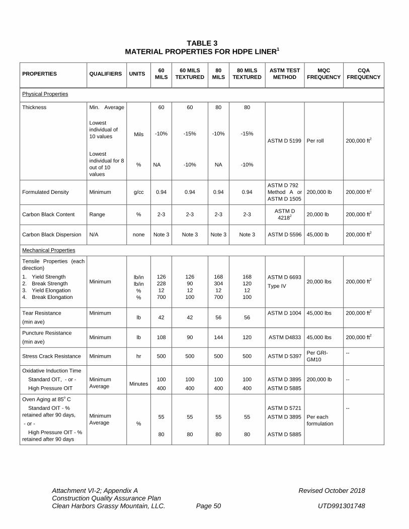
Attachment VI-2; Appendix A Revised October 2018 Construction Quality Assurance Plan Clean Harbors Grassy Mountain, LLC. Page 50 UTD991301748
TABLE 3 MATERIAL PROPERTIES FOR HDPE LINER1
PROPERTIES QUALIFIERS UNITS 60 MILS
60 MILS TEXTURED
80 MILS
80 MILS TEXTURED
ASTM TEST METHOD
MQC FREQUENCY
CQA FREQUENCY
Physical Properties
Thickness Min. Average Lowest individual of 10 values Lowest individual for 8 out of 10 values
Mils
%
60
-10%
NA
60
-15%
-10%
80
-10%
NA
80
-15%
-10%
ASTM D 5199 Per roll 200,000 ft2
Formulated Density Minimum g/cc 0.94 0.94 0.94 0.94 ASTM D 792 Method A or ASTM D 1505
200,000 lb 200,000 ft2
Carbon Black Content Range % 2-3 2-3 2-3 2-3 ASTM D 42182 20,000 lb 200,000 ft2
Carbon Black Dispersion N/A none Note 3 Note 3 Note 3 Note 3 ASTM D 5596 45,000 lb 200,000 ft2
Mechanical Properties
Tensile Properties (each direction) 1. Yield Strength 2. Break Strength 3. Yield Elongation 4. Break Elongation
Minimum
lb/in lb/in % %
126 228 12 700
126 90 12
100
168 304 12 700
168 120 12
100
ASTM D 6693 Type IV
20,000 lbs 200,000 ft2
Tear Resistance (min ave)
Minimum lb 42 42 56 56
ASTM D 1004 45,000 lbs 200,000 ft2
Puncture Resistance (min ave)
Minimum lb 108 90 144 120 ASTM D4833 45,000 lbs 200,000 ft2
Stress Crack Resistance Minimum hr 500 500 500 500 ASTM D 5397 Per GRI-GM10
--
Oxidative Induction Time Standard OIT, - or - High Pressure OIT
Minimum Average
Minutes
100 400
100 400
100 400
100 400
ASTM D 3895 ASTM D 5885
200,000 lb
--
Oven Aging at 85o C Standard OIT - % retained after 90 days, - or - High Pressure OIT - % retained after 90 days
Minimum Average
%
55
80
55
80
55
80
55
80
ASTM D 5721 ASTM D 3895 ASTM D 5885
Per each formulation
--
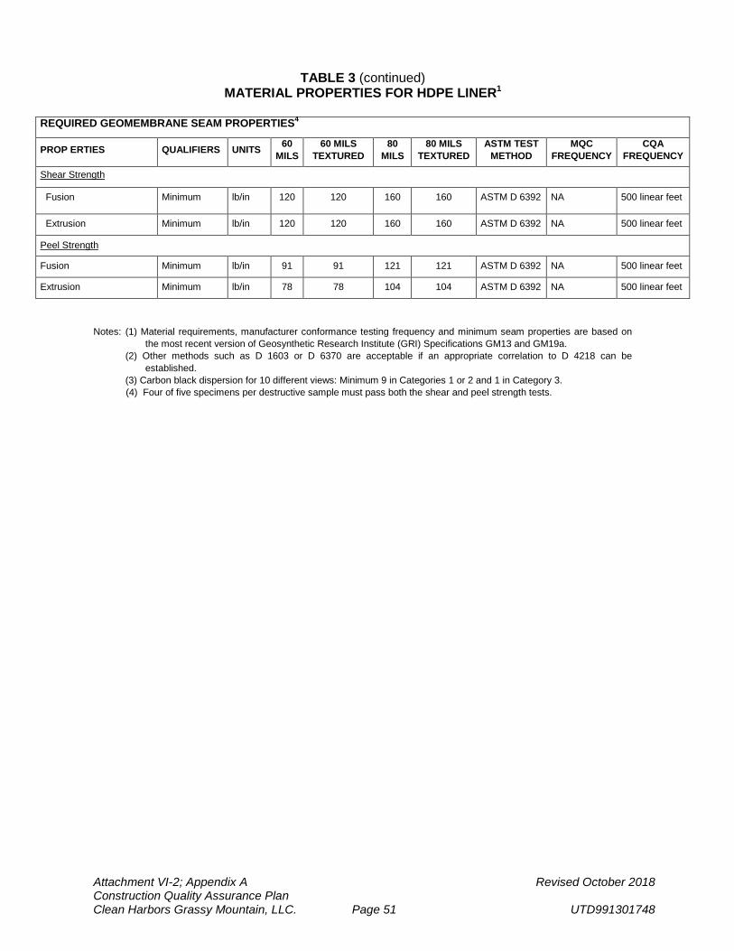
Attachment VI-2; Appendix A Revised October 2018 Construction Quality Assurance Plan Clean Harbors Grassy Mountain, LLC. Page 51 UTD991301748
TABLE 3 (continued) MATERIAL PROPERTIES FOR HDPE LINER1
Notes: (1) Material requirements, manufacturer conformance testing frequency and minimum seam properties are based on
the most recent version of Geosynthetic Research Institute (GRI) Specifications GM13 and GM19a. (2) Other methods such as D 1603 or D 6370 are acceptable if an appropriate correlation to D 4218 can be
established. (3) Carbon black dispersion for 10 different views: Minimum 9 in Categories 1 or 2 and 1 in Category 3.
(4) Four of five specimens per destructive sample must pass both the shear and peel strength tests.
REQUIRED GEOMEMBRANE SEAM PROPERTIES4
PROP ERTIES QUALIFIERS UNITS 60 MILS
60 MILS TEXTURED
80 MILS
80 MILS TEXTURED
ASTM TEST METHOD
MQC FREQUENCY
CQA FREQUENCY
Shear Strength
Fusion Minimum lb/in 120 120 160 160 ASTM D 6392 NA 500 linear feet
Extrusion Minimum lb/in 120 120 160 160 ASTM D 6392 NA 500 linear feet
Peel Strength
Fusion Minimum lb/in 91 91 121 121 ASTM D 6392 NA 500 linear feet
Extrusion Minimum lb/in 78 78 104 104 ASTM D 6392 NA 500 linear feet
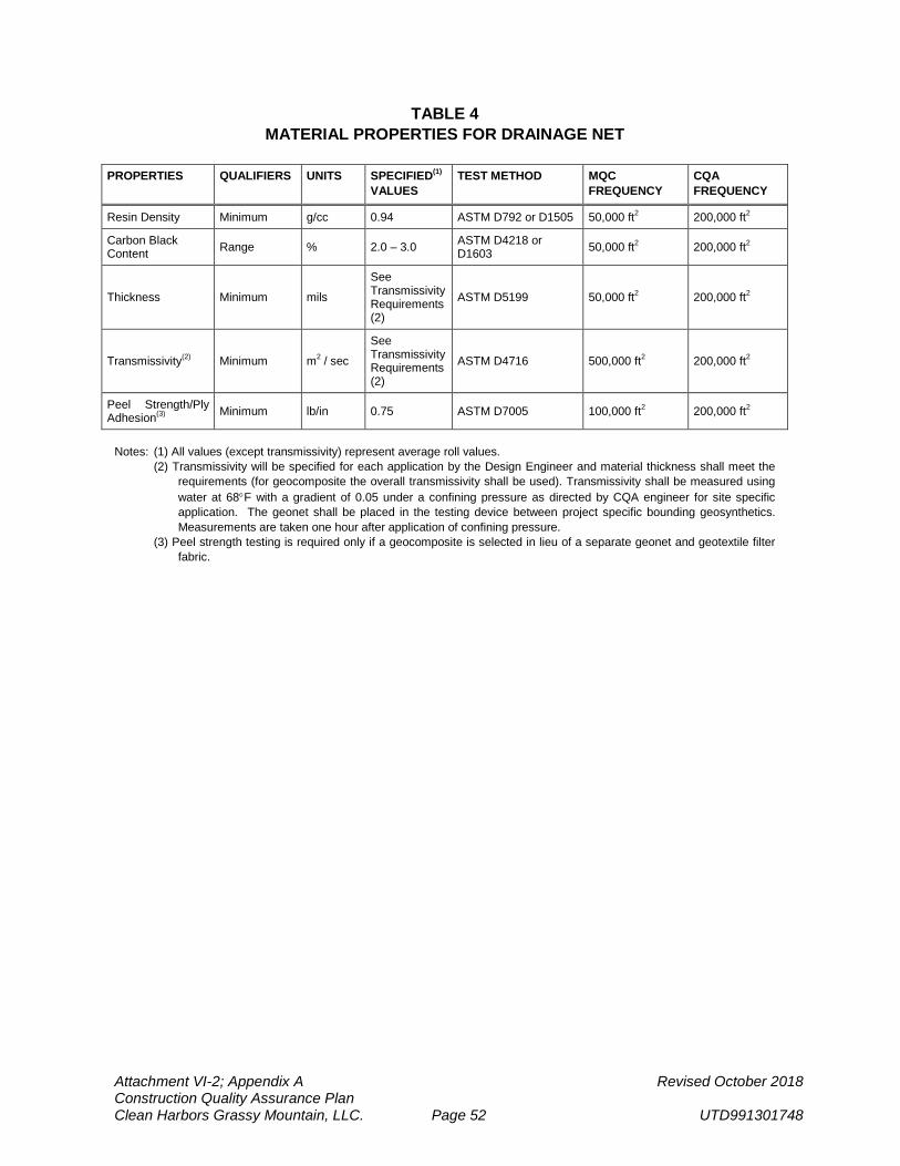
Attachment VI-2; Appendix A Revised October 2018 Construction Quality Assurance Plan Clean Harbors Grassy Mountain, LLC. Page 52 UTD991301748
TABLE 4
MATERIAL PROPERTIES FOR DRAINAGE NET
PROPERTIES QUALIFIERS UNITS SPECIFIED(1) VALUES
TEST METHOD MQC FREQUENCY
CQA FREQUENCY
Resin Density Minimum g/cc 0.94 ASTM D792 or D1505 50,000 ft2 200,000 ft2
Carbon Black Content Range % 2.0 – 3.0 ASTM D4218 or
D1603 50,000 ft2 200,000 ft2
Thickness Minimum mils
See Transmissivity Requirements (2)
ASTM D5199 50,000 ft2 200,000 ft2
Transmissivity(2) Minimum m2 / sec
See Transmissivity Requirements (2)
ASTM D4716 500,000 ft2 200,000 ft2
Peel Strength/Ply Adhesion(3) Minimum lb/in 0.75 ASTM D7005 100,000 ft2 200,000 ft2
Notes: (1) All values (except transmissivity) represent average roll values. (2) Transmissivity will be specified for each application by the Design Engineer and material thickness shall meet the
requirements (for geocomposite the overall transmissivity shall be used). Transmissivity shall be measured using water at 68°F with a gradient of 0.05 under a confining pressure as directed by CQA engineer for site specific application. The geonet shall be placed in the testing device between project specific bounding geosynthetics. Measurements are taken one hour after application of confining pressure.
(3) Peel strength testing is required only if a geocomposite is selected in lieu of a separate geonet and geotextile filter fabric.
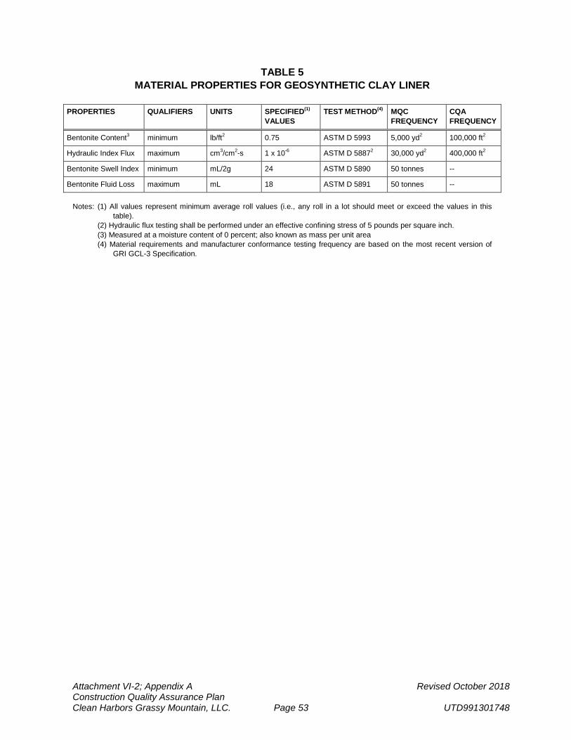
Attachment VI-2; Appendix A Revised October 2018 Construction Quality Assurance Plan Clean Harbors Grassy Mountain, LLC. Page 53 UTD991301748
TABLE 5
MATERIAL PROPERTIES FOR GEOSYNTHETIC CLAY LINER
PROPERTIES QUALIFIERS UNITS SPECIFIED(1) VALUES
TEST METHOD(4) MQC FREQUENCY
CQA FREQUENCY
Bentonite Content3 minimum lb/ft2 0.75 ASTM D 5993 5,000 yd2 100,000 ft2
Hydraulic Index Flux maximum cm3/cm2-s 1 x 10⁻⁶ ASTM D 58872 30,000 yd2 400,000 ft2
Bentonite Swell Index minimum mL/2g 24 ASTM D 5890 50 tonnes --
Bentonite Fluid Loss maximum mL 18 ASTM D 5891 50 tonnes -- Notes: (1) All values represent minimum average roll values (i.e., any roll in a lot should meet or exceed the values in this
table). (2) Hydraulic flux testing shall be performed under an effective confining stress of 5 pounds per square inch. (3) Measured at a moisture content of 0 percent; also known as mass per unit area (4) Material requirements and manufacturer conformance testing frequency are based on the most recent version of
GRI GCL-3 Specification.
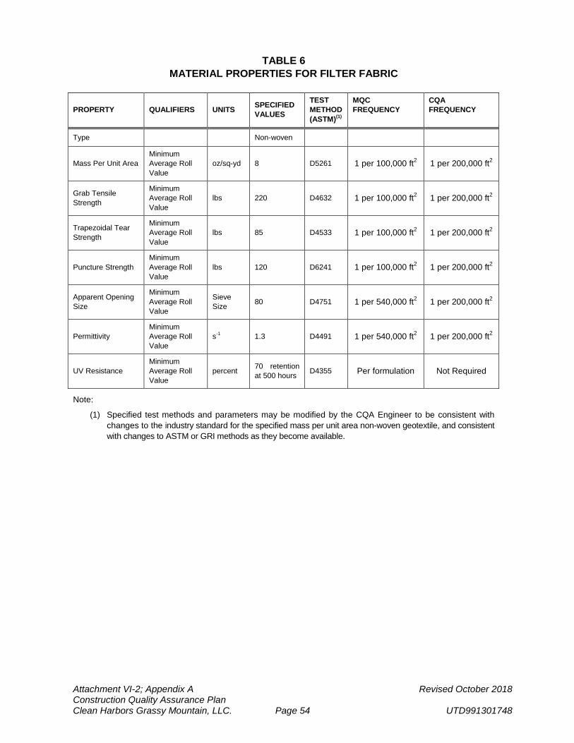
Attachment VI-2; Appendix A Revised October 2018 Construction Quality Assurance Plan Clean Harbors Grassy Mountain, LLC. Page 54 UTD991301748
TABLE 6 MATERIAL PROPERTIES FOR FILTER FABRIC
PROPERTY QUALIFIERS UNITS SPECIFIED VALUES
TEST METHOD (ASTM)(1)
MQC FREQUENCY
CQA FREQUENCY
Type Non-woven
Mass Per Unit Area Minimum Average Roll Value
oz/sq-yd 8 D5261 1 per 100,000 ft2 1 per 200,000 ft2
Grab Tensile Strength
Minimum Average Roll Value
lbs 220 D4632 1 per 100,000 ft2 1 per 200,000 ft2
Trapezoidal Tear Strength
Minimum Average Roll Value
lbs 85 D4533 1 per 100,000 ft2 1 per 200,000 ft2
Puncture Strength Minimum Average Roll Value
lbs 120 D6241 1 per 100,000 ft2 1 per 200,000 ft2
Apparent Opening Size
Minimum Average Roll Value
Sieve Size 80 D4751 1 per 540,000 ft2 1 per 200,000 ft2
Permittivity Minimum Average Roll Value
s-1 1.3 D4491 1 per 540,000 ft2 1 per 200,000 ft2
UV Resistance Minimum Average Roll Value
percent 70 retention at 500 hours D4355 Per formulation Not Required
Note:
(1) Specified test methods and parameters may be modified by the CQA Engineer to be consistent with changes to the industry standard for the specified mass per unit area non-woven geotextile, and consistent with changes to ASTM or GRI methods as they become available.
APPENDIX A-1: TEST METHODS
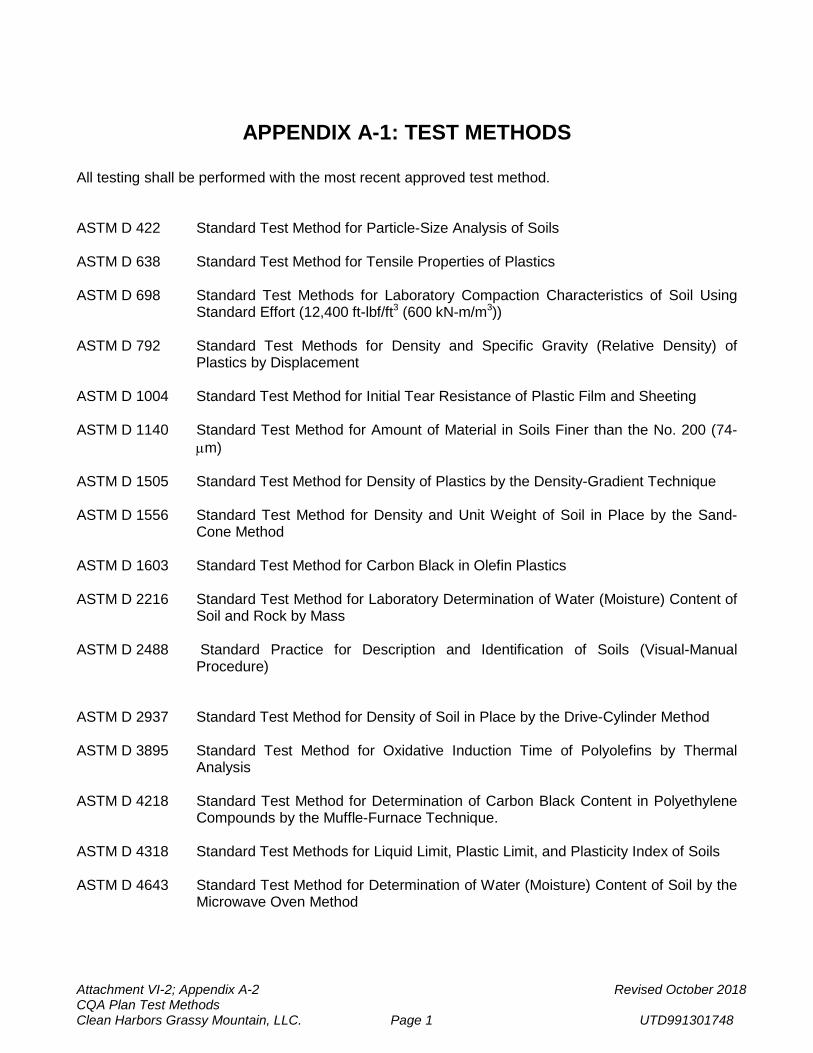
Attachment VI-2; Appendix A-2 Revised October 2018 CQA Plan Test Methods Clean Harbors Grassy Mountain, LLC. Page 1 UTD991301748
APPENDIX A-1: TEST METHODS
All testing shall be performed with the most recent approved test method. ASTM D 422 Standard Test Method for Particle-Size Analysis of Soils ASTM D 638 Standard Test Method for Tensile Properties of Plastics ASTM D 698 Standard Test Methods for Laboratory Compaction Characteristics of Soil Using
Standard Effort (12,400 ft-lbf/ft3 (600 kN-m/m3)) ASTM D 792 Standard Test Methods for Density and Specific Gravity (Relative Density) of
Plastics by Displacement ASTM D 1004 Standard Test Method for Initial Tear Resistance of Plastic Film and Sheeting ASTM D 1140 Standard Test Method for Amount of Material in Soils Finer than the No. 200 (74-
µm) ASTM D 1505 Standard Test Method for Density of Plastics by the Density-Gradient Technique ASTM D 1556 Standard Test Method for Density and Unit Weight of Soil in Place by the Sand-
Cone Method ASTM D 1603 Standard Test Method for Carbon Black in Olefin Plastics ASTM D 2216 Standard Test Method for Laboratory Determination of Water (Moisture) Content of
Soil and Rock by Mass ASTM D 2488 Standard Practice for Description and Identification of Soils (Visual-Manual
Procedure) ASTM D 2937 Standard Test Method for Density of Soil in Place by the Drive-Cylinder Method ASTM D 3895 Standard Test Method for Oxidative Induction Time of Polyolefins by Thermal
Analysis ASTM D 4218 Standard Test Method for Determination of Carbon Black Content in Polyethylene
Compounds by the Muffle-Furnace Technique. ASTM D 4318 Standard Test Methods for Liquid Limit, Plastic Limit, and Plasticity Index of Soils ASTM D 4643 Standard Test Method for Determination of Water (Moisture) Content of Soil by the
Microwave Oven Method
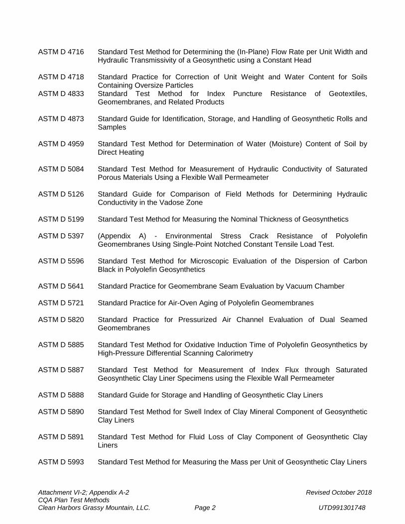
Attachment VI-2; Appendix A-2 Revised October 2018 CQA Plan Test Methods Clean Harbors Grassy Mountain, LLC. Page 2 UTD991301748
ASTM D 4716 Standard Test Method for Determining the (In-Plane) Flow Rate per Unit Width and Hydraulic Transmissivity of a Geosynthetic using a Constant Head
ASTM D 4718 Standard Practice for Correction of Unit Weight and Water Content for Soils
Containing Oversize Particles ASTM D 4833 Standard Test Method for Index Puncture Resistance of Geotextiles,
Geomembranes, and Related Products ASTM D 4873 Standard Guide for Identification, Storage, and Handling of Geosynthetic Rolls and
Samples ASTM D 4959 Standard Test Method for Determination of Water (Moisture) Content of Soil by
Direct Heating ASTM D 5084 Standard Test Method for Measurement of Hydraulic Conductivity of Saturated
Porous Materials Using a Flexible Wall Permeameter ASTM D 5126 Standard Guide for Comparison of Field Methods for Determining Hydraulic
Conductivity in the Vadose Zone ASTM D 5199 Standard Test Method for Measuring the Nominal Thickness of Geosynthetics ASTM D 5397 (Appendix A) - Environmental Stress Crack Resistance of Polyolefin
Geomembranes Using Single-Point Notched Constant Tensile Load Test. ASTM D 5596 Standard Test Method for Microscopic Evaluation of the Dispersion of Carbon
Black in Polyolefin Geosynthetics ASTM D 5641 Standard Practice for Geomembrane Seam Evaluation by Vacuum Chamber ASTM D 5721 Standard Practice for Air-Oven Aging of Polyolefin Geomembranes ASTM D 5820 Standard Practice for Pressurized Air Channel Evaluation of Dual Seamed
Geomembranes ASTM D 5885 Standard Test Method for Oxidative Induction Time of Polyolefin Geosynthetics by
High-Pressure Differential Scanning Calorimetry ASTM D 5887 Standard Test Method for Measurement of Index Flux through Saturated
Geosynthetic Clay Liner Specimens using the Flexible Wall Permeameter ASTM D 5888 Standard Guide for Storage and Handling of Geosynthetic Clay Liners ASTM D 5890 Standard Test Method for Swell Index of Clay Mineral Component of Geosynthetic
Clay Liners ASTM D 5891 Standard Test Method for Fluid Loss of Clay Component of Geosynthetic Clay
Liners ASTM D 5993 Standard Test Method for Measuring the Mass per Unit of Geosynthetic Clay Liners
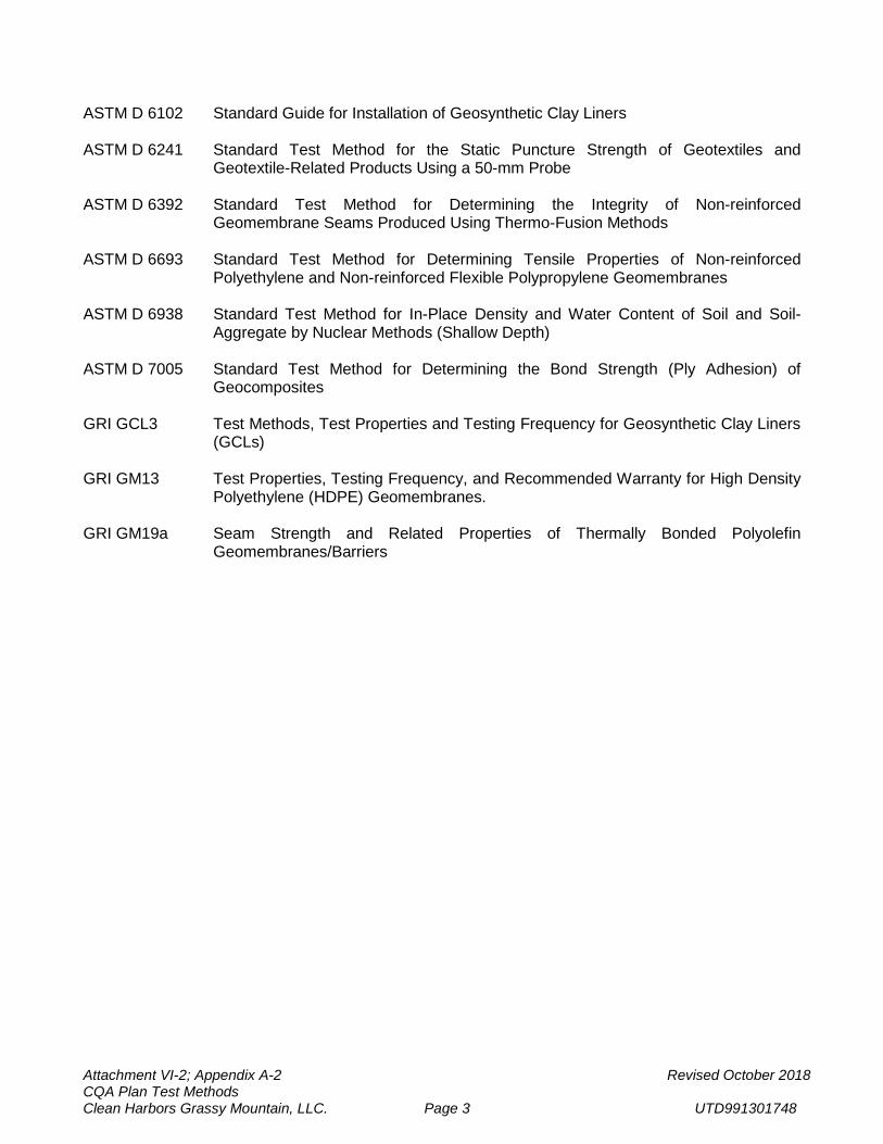
Attachment VI-2; Appendix A-2 Revised October 2018 CQA Plan Test Methods Clean Harbors Grassy Mountain, LLC. Page 3 UTD991301748
ASTM D 6102 Standard Guide for Installation of Geosynthetic Clay Liners ASTM D 6241 Standard Test Method for the Static Puncture Strength of Geotextiles and
Geotextile-Related Products Using a 50-mm Probe ASTM D 6392 Standard Test Method for Determining the Integrity of Non-reinforced
Geomembrane Seams Produced Using Thermo-Fusion Methods ASTM D 6693 Standard Test Method for Determining Tensile Properties of Non-reinforced
Polyethylene and Non-reinforced Flexible Polypropylene Geomembranes ASTM D 6938 Standard Test Method for In-Place Density and Water Content of Soil and Soil-
Aggregate by Nuclear Methods (Shallow Depth) ASTM D 7005 Standard Test Method for Determining the Bond Strength (Ply Adhesion) of
Geocomposites GRI GCL3 Test Methods, Test Properties and Testing Frequency for Geosynthetic Clay Liners
(GCLs) GRI GM13 Test Properties, Testing Frequency, and Recommended Warranty for High Density
Polyethylene (HDPE) Geomembranes. GRI GM19a Seam Strength and Related Properties of Thermally Bonded Polyolefin
Geomembranes/Barriers
APPENDIX A-2
PERMEABILITY TEST PROCEDURES
Attachment VI-2; Appendix A-2 October 2018 CQA Plan Test Methods Clean Harbors Grassy Mountain, LLC. Page 1 UTD991301748
A-2-1: PROCEDURE FOR SEALED SINGLE RING INFILTROMETER FIELD PERMEABILITY TEST
The sealed single ring infiltrometer testing procedure for field permeability testing is as follows:
1. Equipment a. Metal Ring – With a minimum area of 1294 cm2. The bottom of the ring is beveled
for a cutting edge. A flange welded to the top of the metal ring is provided to allow connection of a lid.
b. Lid – Cover for the metal ring. Provided with a gasket to seal the cover to the ring flange. Also provided with a nipple to connect a water supply hose and vent valve.
c. Water Reservoir – Supplies water for the saturation portion of the test. Connects to the lid and the readout tube.
d. Readout Tube – Approximately .32 cm diameter to measure the flow of water into the system.
e. Stand – Method to support the water reservoir and the readout tube. f. Static Weight Penetrometer – The probe construction will be a stainless steel rod
with a quarter (1/4) inch nominal diameter and a flat tip. The probe will have a weight such that the minimum tip pressure is one hundred pounds per square inch (100 psi).
2. Testing Procedures
a. Metal rings with a minimum radius of 20.3 cm will be utilized for permeability testing
during test pad construction. b. Prepare the area to be tested by smoothing the ground surface and removing any
loose or disturbed soil. c. Place the metal ring on the area prepared. Push the metal ring at least 15.2 cm into
the soil. d. Remove any soil disturbed from inside the metal ring by the insertion process. e. Seal the inside of the metal ring by compacting the soil immediately adjacent to the
ring. f. Place a small plate on the soil surface and pour water over the plate into the ring,
filling the ring with water to within approximately 1.3 cm of the top of the ring. g. Place the lid on the ring and seal with clamps or other devices. h. Connect the water reservoir and readout tube to the lid and set on support stand. i. Fill the system with water, filling the ring, reservoir and all hoses. j. Secure the reservoir at least 91.4 cm above the ring. k. Allow the water to permeate into the soil for a minimum of 4 hours (for test pads
only: Minimum 0.76 cm wet from depth for each wet front depth test. The average wet front depth for all 9 SSRI tests performed for each test pad must be at least 0.86 cm).
l. Fill the readout tube with water and secure the readout tube so that the water level in the tube is approximately 152.4 cm above the ring. Allow the readings to stabilize prior to starting the test. The water level shall be greater than or equal to 121.9 cm when the test starts. Record the initial height of the water above the soil surface inside the ring.
Attachment VI-2; Appendix A-2 October 2018 CQA Plan Test Methods Clean Harbors Grassy Mountain, LLC. Page 2 UTD991301748
m. Record the water level in the readout tube every 20 seconds for 8 minutes. Plot the water drop over time.
n. Dismantle the system and measure the temperature at the soil-water interface (inside the ring, measured in ºC). The appropriate Temperature Correction Factor shall be identified from Figure 1 of the Field Permeability Test Form EC-1906, or from Table 1 of ASTM D 5084. Then measure the depth that the water penetrated into the soil, using the static weight penetrometer. The average of at least three wet front depth tests shall be used for calculating the water penetration depth.
o. Calculate the Change in Head during the test based on a linear regression analysis of the plotted results.
p. Calculate the permeability. Report permeability to two significant digits.
3. Documentation Record the following items. (Record all length measurements in cm.) a. Date and time soil saturation began and when permeability test readings were
taken. b. Test location and elevation. c. Timed water drop readings. d. Height of water at beginning of readings. e. Size of ring and readout tube (if required). f. Soil-water interface temperature. g. Average depth of wet front. h. Plot of water level drop with time. i. Plot the calculated regression line of water level drop with time. j. Calculated permeability.
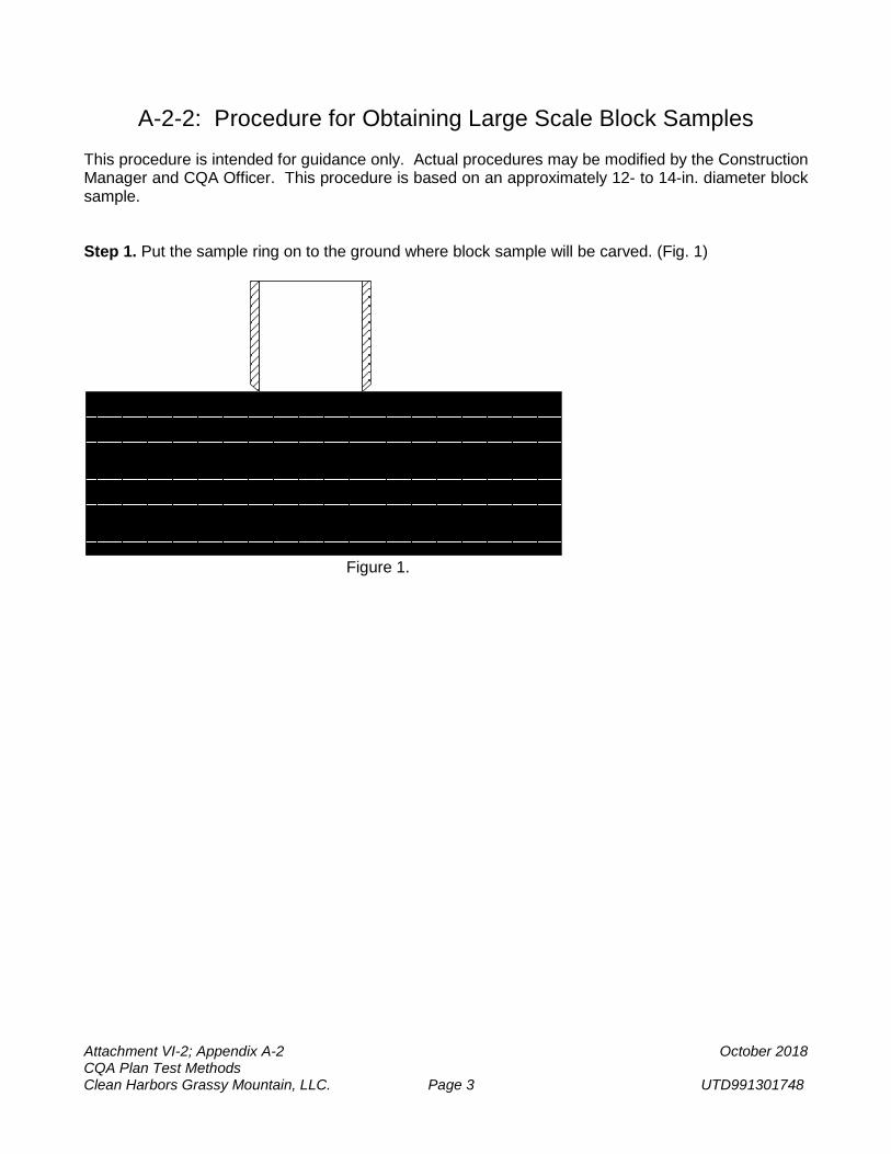
Attachment VI-2; Appendix A-2 October 2018 CQA Plan Test Methods Clean Harbors Grassy Mountain, LLC. Page 3 UTD991301748
A-2-2: Procedure for Obtaining Large Scale Block Samples This procedure is intended for guidance only. Actual procedures may be modified by the Construction Manager and CQA Officer. This procedure is based on an approximately 12- to 14-in. diameter block sample. Step 1. Put the sample ring on to the ground where block sample will be carved. (Fig. 1)
Figure 1.
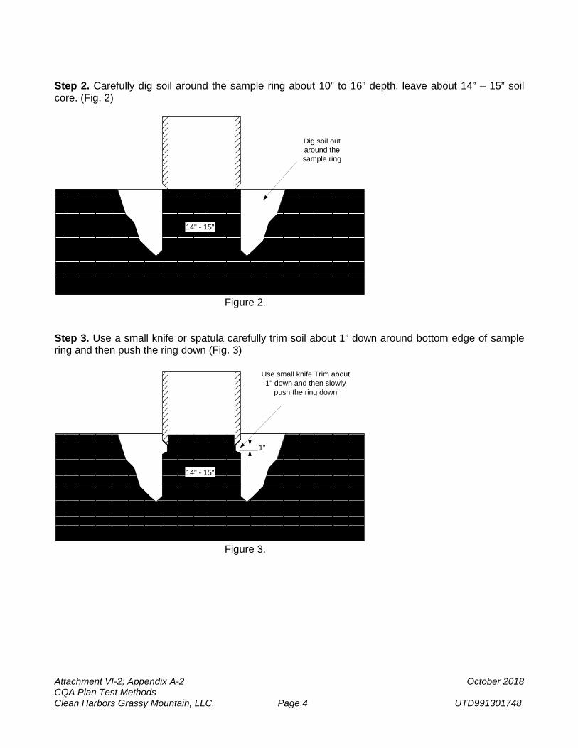
Attachment VI-2; Appendix A-2 October 2018 CQA Plan Test Methods Clean Harbors Grassy Mountain, LLC. Page 4 UTD991301748
Step 2. Carefully dig soil around the sample ring about 10” to 16” depth, leave about 14” – 15” soil core. (Fig. 2)
14" - 15"
Dig soil outaround thesample ring
Figure 2. Step 3. Use a small knife or spatula carefully trim soil about 1” down around bottom edge of sample ring and then push the ring down (Fig. 3)
14" - 15"
1"
Use small knife Trim about1" down and then slowly
push the ring down
Figure 3.
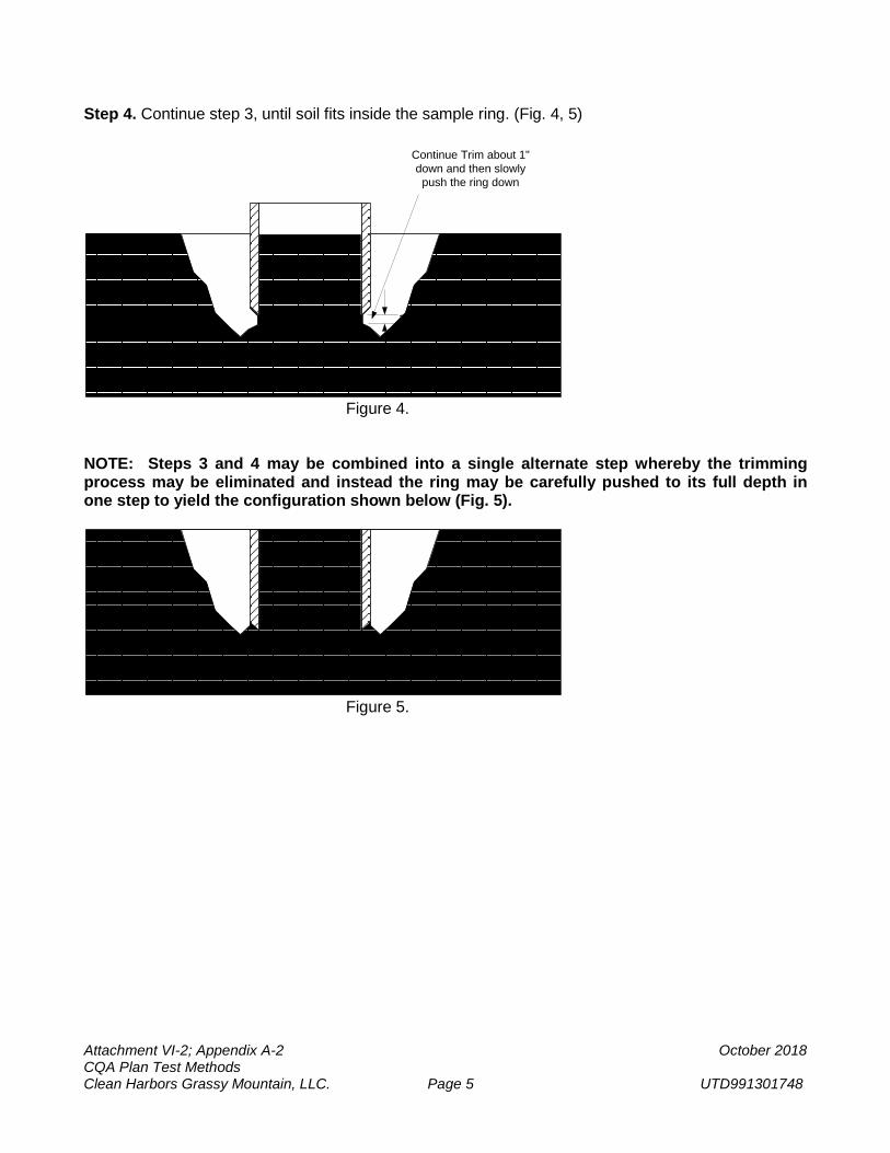
Attachment VI-2; Appendix A-2 October 2018 CQA Plan Test Methods Clean Harbors Grassy Mountain, LLC. Page 5 UTD991301748
Step 4. Continue step 3, until soil fits inside the sample ring. (Fig. 4, 5)
1"
Continue Trim about 1"down and then slowlypush the ring down
Figure 4. NOTE: Steps 3 and 4 may be combined into a single alternate step whereby the trimming process may be eliminated and instead the ring may be carefully pushed to its full depth in one step to yield the configuration shown below (Fig. 5).
Figure 5.
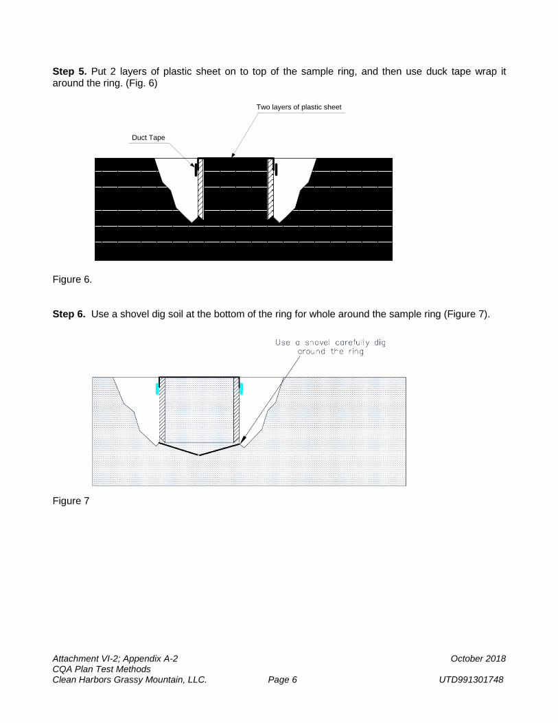
Attachment VI-2; Appendix A-2 October 2018 CQA Plan Test Methods Clean Harbors Grassy Mountain, LLC. Page 6 UTD991301748
Step 5. Put 2 layers of plastic sheet on to top of the sample ring, and then use duck tape wrap it around the ring. (Fig. 6)
Two layers of plastic sheet
Duct Tape
Figure 6. Step 6. Use a shovel dig soil at the bottom of the ring for whole around the sample ring (Figure 7).
Figure 7
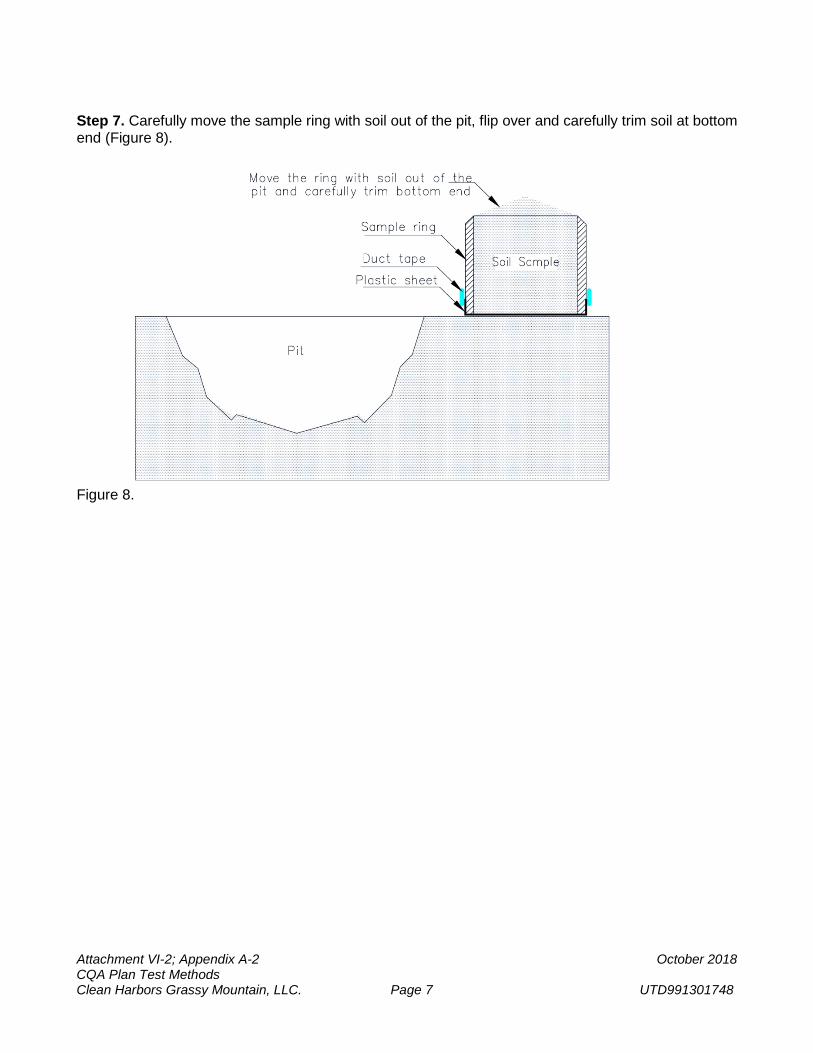
Attachment VI-2; Appendix A-2 October 2018 CQA Plan Test Methods Clean Harbors Grassy Mountain, LLC. Page 7 UTD991301748
Step 7. Carefully move the sample ring with soil out of the pit, flip over and carefully trim soil at bottom end (Figure 8).
Figure 8.
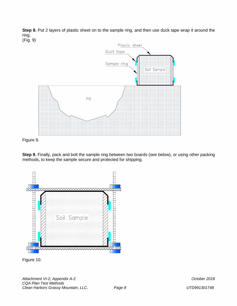
Attachment VI-2; Appendix A-2 October 2018 CQA Plan Test Methods Clean Harbors Grassy Mountain, LLC. Page 8 UTD991301748
Step 8. Put 2 layers of plastic sheet on to the sample ring, and then use duck tape wrap it around the ring. (Fig. 9)
Figure 9. Step 9. Finally, pack and bolt the sample ring between two boards (see below), or using other packing methods, to keep the sample secure and protected for shipping.
Figure 10.