Embed Size (px)
Citation preview
DISTRIBUTION STATEMENT A: Approved for public release; distribution is unlimited.
NONRESIDENT
TRAININGCOURSE
February 1998
Construction MechanicBasic, Volume 1NAVEDTRA 14264

DISTRIBUTION STATEMENT A: Approved for public release; distribution is unlimited.
Although the words “he,” “him,” and“his” are used sparingly in this course toenhance communication, they are notintended to be gender driven or to affront ordiscriminate against anyone.

i
PREFACE
By enrolling in this self-study course, you have demonstrated a desire to improve yourself and the Navy.Remember, however, this self-study course is only one part of the total Navy training program. Practicalexperience, schools, selected reading, and your desire to succeed are also necessary to successfully roundout a fully meaningful training program.
THE COURSE: This self-study course is organized into subject matter areas, each containing learningobjectives to help you determine what you should learn along with text and illustrations to help youunderstand the information. The subject matter reflects day-to-day requirements and experiences ofpersonnel in the rating or skill area. It also reflects guidance provided by Enlisted Community Managers(ECMs) and other senior personnel, technical references, instructions, etc., and either the occupational ornaval standards, which are listed in the Manual of Navy Enlisted Manpower Personnel Classificationsand Occupational Standards, NAVPERS 18068.
THE QUESTIONS: The questions that appear in this course are designed to help you understand thematerial in the text.
VALUE: In completing this course, you will improve your military and professional knowledge.Importantly, it can also help you study for the Navy-wide advancement in rate examination. If you arestudying and discover a reference in the text to another publication for further information, look it up.
1998 Edition Prepared byCMC(SCW) Charles Lathan
Published byNAVAL EDUCATION AND TRAINING
PROFESSIONAL DEVELOPMENTAND TECHNOLOGY CENTER
NAVSUP Logistics Tracking Number0504-LP-026-8960

ii
Sailor’s Creed
“I am a United States Sailor.
I will support and defend theConstitution of the United States ofAmerica and I will obey the ordersof those appointed over me.
I represent the fighting spirit of theNavy and those who have gonebefore me to defend freedom anddemocracy around the world.
I proudly serve my country’s Navycombat team with honor, courageand commitment.
I am committed to excellence andthe fair treatment of all.”
CONTENTS
CHAPTER PAGE
1. Technical Adminstration . . . . . . . . . . . . . . . . . . . . . . . 1-1
2. Principles of an Internal Combustion Engine. . . . . . . . . . . . . 2-1
3. Construction of an Internal Combustion Engine . . . . . . . . . . . 3-1
4. Gasoline Fuel Systems . . . . . . . . . . . . . . . . . . . . . . . . 4-1
5. Diesel Fuel Systems . . . . . . . . . . . . . . . . . . . . . . . . . 5-1
6. Cooling and Lubricating Systems . . . . . . . . . . . . . . . . . 6-1
APPENDIX
I. Glossary . . . . . . . . . . . . . . . . . . . . . . . . . . . . . . . AI-1
II. Answer Key. . . . . . . . . . . . . . . . . . . . . . . . . . . . . AII-1
III. References Used To Develop This TRAMAN. . . . . . . . . . . AIII-1
INDEX. . . . . . . . . . . . . . . . . . . . . . . . . . . . . . . . . . INDEX-l
NONRESIDENT TRAINING COURSE follows Index
iii
SUMMARY OF CONSTRUCTIONMECHANIC BASIC
VOLUME 1
Construction Mechanic Basic, Volume 1, NAVEDTRA 14264, consists ofchapters on Technical Adminstration; Principles of an Internal Combustion Engine;Construction of an Internal Combustion Engine; Gasoline Fuel Systems; FuelDiesel Fuel Systems; and Cooling and Lubricating Systems.
VOLUME 2
Construction Mechanic Basic, Volume 2, NAVEDTRA 14273, consists ofchapters on Basic Automotive Electricity; Automotive Electrical Circuits andWiring; Hydraulic and Pneumatics Systems; Automotive Clutches andTransmissions; Drive Lines, Differentials, Axles, and Power Train Accessories;Construction Equipment Power Trains; Brakes; and Automotive Chassis and Body.
iv
v
INSTRUCTIONS FOR TAKING THE COURSE
ASSIGNMENTS
The text pages that you are to study are listed atthe beginning of each assignment. Study thesepages carefully before attempting to answer thequestions. Pay close attention to tables andillustrations and read the learning objectives.The learning objectives state what you should beable to do after studying the material. Answeringthe questions correctly helps you accomplish theobjectives.
SELECTING YOUR ANSWERS
Read each question carefully, then select theBEST answer. You may refer freely to the text.The answers must be the result of your ownwork and decisions. You are prohibited fromreferring to or copying the answers of others andfrom giving answers to anyone else taking thecourse.
SUBMITTING YOUR ASSIGNMENTS
To have your assignments graded, you must beenrolled in the course with the NonresidentTraining Course Administration Branch at theNaval Education and Training ProfessionalDevelopment and Technology Center(NETPDTC). Following enrollment, there aretwo ways of having your assignments graded:(1) use the Internet to submit your assignmentsas you complete them, or (2) send all theassignments at one time by mail to NETPDTC.
Grading on the Internet: Advantages toInternet grading are:
• you may submit your answers as soon asyou complete an assignment, and
• you get your results faster; usually by thenext working day (approximately 24 hours).
In addition to receiving grade results for eachassignment, you will receive course completionconfirmation once you have completed all the
assignments. To submit your assignmentanswers via the Internet, go to:
http://courses.cnet.navy.mil
Grading by Mail: When you submit answersheets by mail, send all of your assignments atone time. Do NOT submit individual answersheets for grading. Mail all of your assignmentsin an envelope, which you either provideyourself or obtain from your nearest EducationalServices Officer (ESO). Submit answer sheetsto:
COMMANDING OFFICERNETPDTC N3316490 SAUFLEY FIELD ROADPENSACOLA FL 32559-5000
Answer Sheets: All courses include one“scannable” answer sheet for each assignment.These answer sheets are preprinted with yourSSN, name, assignment number, and coursenumber. Explanations for completing the answersheets are on the answer sheet.
Do not use answer sheet reproductions: Useonly the original answer sheets that weprovide— reproductions will not work with ourscanning equipment and cannot be processed.
Follow the instructions for marking youranswers on the answer sheet. Be sure that blocks1, 2, and 3 are filled in correctly. Thisinformation is necessary for your course to beproperly processed and for you to receive creditfor your work.
COMPLETION TIME
Courses must be completed within 12 monthsfrom the date of enrollment. This includes timerequired to resubmit failed assignments.
vi
PASS/FAIL ASSIGNMENT PROCEDURES
If your overall course score is 3.2 or higher, youwill pass the course and will not be required toresubmit assignments. Once your assignmentshave been graded you will receive coursecompletion confirmation.
If you receive less than a 3.2 on any assignmentand your overall course score is below 3.2, youwill be given the opportunity to resubmit failedassignments. You may resubmit failedassignments only once . Internet students willreceive notification when they have failed anassignment--they may then resubmit failedassignments on the web site. Internet studentsmay view and print results for failedassignments from the web site. Students whosubmit by mail will receive a failing result letterand a new answer sheet for resubmission of eachfailed assignment.
COMPLETION CONFIRMATION
After successfully completing this course, youwill receive a letter of completion.
ERRATA
Errata are used to correct minor errors or deleteobsolete information in a course. Errata mayalso be used to provide instructions to thestudent. If a course has an errata, it will beincluded as the first page(s) after the front cover.Errata for all courses can be accessed andviewed/downloaded at:
http:/ /www.advancement.cnet.navy.mil
STUDENT FEEDBACK QUESTIONS
We value your suggestions, questions, andcriticisms on our courses. If you would like tocommunicate with us regarding this course, weencourage you, if possible, to use e-mail. If youwrite or fax, please use a copy of the StudentComment form that follows this page.
For subject matter questions:
E-mail: [email protected]: Comm: (850) 452-1001, Ext. 1826
DSN: 922-1001, Ext. 1826FAX: (850) 452-1370(Do not fax answer sheets.)
Address: COMMANDING OFFICERNETPDTC (CODE 314)6490 SAUFLEY FIELD ROADPENSACOLA FL 32509-5237
For enrollment, shipping, grading, orcompletion letter questions
E-mail: [email protected]: Toll Free: 877-264-8583
Comm: (850) 452-1511/1181/1859DSN: 922-1511/1181/1859FAX: (850) 452-1370(Do not fax answer sheets.)
Address: COMMANDING OFFICERNETPDTC (CODE N331)6490 SAUFLEY FIELD ROADPENSACOLA FL 32559-5000
NAVAL RESERVE RETIREMENT CREDIT
If you are a member of the Naval Reserve, youwill receive retirement points if you areauthorized to receive them under currentdirectives governing retirement of NavalReserve personnel. For Naval Reserveretirement, this course is evaluated at 8 points.(Refer to Administrative Procedures for NavalReservists on Inactive Duty, BUPERSINST1001.39, for more information about retirementpoints.)
COURSE OBJECTIVES
In completing this nonresident training course,you will demonstrate a knowledge of the subjectmatter by correctly answering questions on thefollowing subjects: Technical Administration;Principles of an Internal Combustion Engine;Construction of an Internal Combustion Engine;Gasoline Fuel Systems; Diesel Fuel Systems;and Cooling and Lubricating Systems.
vii
Student Comments
Course Title: Construction Mechanic Basic, Volume 1
NAVEDTRA: 14264 Date:
We need some information about you:
Rate/Rank and Name: SSN: Command/Unit
Street Address: City: State/FPO: Zip
Your comments, suggestions, etc.:
Privacy Act Statement: Under authority of Title 5, USC 301, information regarding your military status isrequested in processing your comments and in preparing a reply. This information will not be divulged withoutwritten authorization to anyone other than those within DOD for official use in determining performance.
NETPDTC 1550/41 (Rev 4-00)

CHAPTER 1
TECHNICAL ADMINISTRATION
LEARNING OBJECTIVE: Identify personnel, their functions, and requited paperwork to administer a Battalion Equipment Maintenance Program; recognizemaintenance support requirements for a Civil Engineering Support Equipment(CESE) maintenance program.
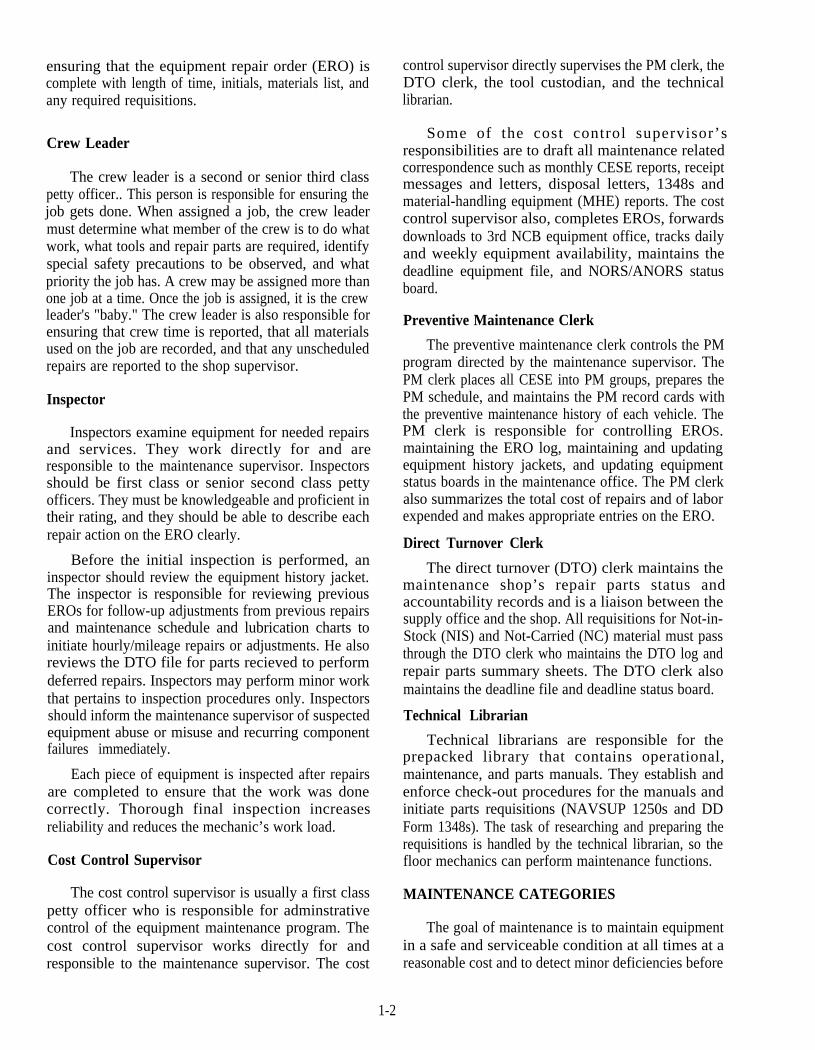
The higher you ascend on the enlisted ladder, themore valuable you are to the Navy. Advancementbrings both increased rewards and responsibilities. Youmust be able to perform various administrative dutieswithin the Construction Mechanic rating, such asopening and closing of equipment repair orders,maintaining history jackets, updating preventivemaintenance record cards, and ordering direct turnover(DTO) or repair parts. The type of activity to which youare attached will determine the way you should carryout your administrative responsibilities.
In this chapter, technical administration as it relatesto the Naval Construction Force is discussed. It isprimarily concerned with maintenance administrationand maintenance support.
MAINTENANCE ADMINISTRATION
LEARNING OBJECTIVE: Recognize theprinciples and techniques of administering theCivil Engineering Support Equipment (CESE)maintenance program.
Administrative guidelines concerning CivilEngineering Support Equipment (CESE) maintenanceare contained in NAVFAC P-300, Management of CivilEngineering Support Equipment andCOMSECONDNCB/COMTHIRDNCBINST 11200.1.
MAINTENANCE ORGANIZATION
The organization of an equipment maintenancesection varies depending upon several factors: numberand type of assigned equipment, number and experienceof personnel, working hours, number of shifts,environmental conditions, and the mission of theactivity. The organization discussed in this chapter isbased upon the operation of a typical Naval Mobile
Construction Battalion (NMCB). The functionsdiscussed are also applicable to small activities whereone person may be required to perform severalfunctions.
Maintenance Supervisor
The maintenance supervisor is the senior mechanicassigned to an activity, usually a senior chief. Thissupervisor is responsible for the maintenance programfor all assigned Civil Engineer Support Equipment(CESE) and all personnel involved. The maintenancesupervisor directly supervises the inspectors, the shopsupervisors, the preventive maintenance and costcontrol clerks, the technical librarian, and the toolroomand parts expediters.
Some of the maintenance supervisorsresponsibilities are to enforce all establishedmaintenance policies, approve all repair actions beforeaccomplishment, approve requisitions for procurementof Not-In-Stock (NIS) and Not-Carried (NC) materials,maintain shop work load files, make all decisionsconcerning deadline CESE, control transfer anddisposal of CESE, supervise the preventivemaintenance (PM) program, and control shop tools andkits. The maintenance supervisor also initiates actionwhen, during maintenance procedures, equipmentabuse or misuse is suspected
Shop Supervisor
The typical NMCB maintenance organization isdivided into three shops: the heavy shop, the light shop,and the support shop. Each shop is supervised by a shopsupervisor. This position is held by a chief or senior firstclass petty officer, who is responsible for the quality ofmaintenance and repairs performed by personnel withinthe shop. The shop supervisor is also responsible for
l-l
ensuring that the equipment repair order (ERO) iscomplete with length of time, initials, materials list, andany required requisitions.
Crew Leader
The crew leader is a second or senior third classpetty officer.. This person is responsible for ensuring thejob gets done. When assigned a job, the crew leadermust determine what member of the crew is to do whatwork, what tools and repair parts are required, identifyspecial safety precautions to be observed, and whatpriority the job has. A crew may be assigned more thanone job at a time. Once the job is assigned, it is the crewleader's "baby." The crew leader is also responsible forensuring that crew time is reported, that all materialsused on the job are recorded, and that any unscheduledrepairs are reported to the shop supervisor.
Inspector
Inspectors examine equipment for needed repairsand services. They work directly for and areresponsible to the maintenance supervisor. Inspectorsshould be first class or senior second class pettyofficers. They must be knowledgeable and proficient intheir rating, and they should be able to describe eachrepair action on the ERO clearly.
1-2
Before the initial inspection is performed, aninspector should review the equipment history jacket.The inspector is responsible for reviewing previousEROs for follow-up adjustments from previous repairsand maintenance schedule and lubrication charts toinitiate hourly/mileage repairs or adjustments. He alsoreviews the DTO file for parts recieved to performdeferred repairs. Inspectors may perform minor workthat pertains to inspection procedures only. Inspectorsshould inform the maintenance supervisor of suspectedequipment abuse or misuse and recurring componentfailures immediately.
Each piece of equipment is inspected after repairsare completed to ensure that the work was donecorrectly. Thorough final inspection increasesreliability and reduces the mechanic’s work load.
Cost Control Supervisor
The cost control supervisor is usually a first classpetty officer who is responsible for adminstrativecontrol of the equipment maintenance program. Thecost control supervisor works directly for andresponsible to the maintenance supervisor. The cost
control supervisor directly supervises the PM clerk, theDTO clerk, the tool custodian, and the technicallibrarian.
Some of the cost control supervisor’sresponsibilities are to draft all maintenance relatedcorrespondence such as monthly CESE reports, receiptmessages and letters, disposal letters, 1348s andmaterial-handling equipment (MHE) reports. The costcontrol supervisor also, completes EROS, forwardsdownloads to 3rd NCB equipment office, tracks dailyand weekly equipment availability, maintains thedeadline equipment file, and NORS/ANORS statusboard.
Preventive Maintenance Clerk
The preventive maintenance clerk controls the PMprogram directed by the maintenance supervisor. ThePM clerk places all CESE into PM groups, prepares thePM schedule, and maintains the PM record cards withthe preventive maintenance history of each vehicle. ThePM clerk is responsible for controlling EROS.maintaining the ERO log, maintaining and updatingequipment history jackets, and updating equipmentstatus boards in the maintenance office. The PM clerkalso summarizes the total cost of repairs and of laborexpended and makes appropriate entries on the ERO.
Direct Turnover Clerk
The direct turnover (DTO) clerk maintains themaintenance shop’s repair parts status andaccountability records and is a liaison between thesupply office and the shop. All requisitions for Not-in-Stock (NIS) and Not-Carried (NC) material must passthrough the DTO clerk who maintains the DTO log andrepair parts summary sheets. The DTO clerk alsomaintains the deadline file and deadline status board.
Technical Librarian
Technical librarians are responsible for theprepacked library that contains operational,maintenance, and parts manuals. They establish andenforce check-out procedures for the manuals andinitiate parts requisitions (NAVSUP 1250s and DDForm 1348s). The task of researching and preparing therequisitions is handled by the technical librarian, so thefloor mechanics can perform maintenance functions.
MAINTENANCE CATEGORIES
The goal of maintenance is to maintain equipmentin a safe and serviceable condition at all times at areasonable cost and to detect minor deficiencies before

they develop into costly repairs. The CESEmaintenance system of the NCF is predicated on threecategories or levels of maintenance as prescribed inNAVFAC P-300 and CONSECONDNCB/COMTHIRDNCBINST 11200.1. These three levelsare as follows: ORGANIZATIONAL, INTER-MEDIATE, and DEPOT. The category of repairsperformed are determined by the nature of the repair;level of repair parts, support, tools, equipment and timeavailable; personnel capabilities; and the tacticalsituation. An activity's range of repair parts support iskeyed to the authorized level of maintenance.
Organizational Maintenance
Organizational maintenance is the responsibility ofand performed by the equipment operator; scheduledpreventive maintenance services are performed bytrained personnel. Operational maintenance consists ofproper equipment operation, safety and serviceabilityinspections, lubrication, and minor adjustments andservices. Organizational maintenance is divided intooperator maintenance and preventive maintenance asspecified below.
1. Operator Maintenance. Each operator isrequired to perform work needed. to maintain theirvehicle in a clean, safe, and serviceable condition. Thisincludes the daily inspections before, during, and afteroperation. It also includes periodic lubrication andadjustments recommended by the equipmentmanufacturer. Operator maintenance is performed toensure early detection of deficiencies.
2. Preventive Maintenance. Preventivemaintenance (PM) is scheduled for the purpose ofmaximizing equipment availability and minimizingrepair costs. PM consists of safety and mechanicalinspections, fluid and filter changes, lubrication, andservices and adjustments beyond an operator'sresponsibility. Operators assist with the work unlessdirected otherwise.
Intermediate Maintenance
Intermediate maintenance is the responsibility ofand performed by a designated maintenance shop. Theextent of intermediate maintenance encompasses theremoval, replacement, repair, alteration, calibration,modification, and the rebuilding and overhauling ofindividual components, assemblies, and subassemblies.Although the rebuilding and overhauling of majorassemblies are included, only essential repairs must beaccomplished to ensure safe and serviceable
equipment. Intermediate maintenance requires a higherdegree of skill than organizational maintenance. Thereis a larger assortment of repair parts, more precisiontools, and other types of test equipment involved.
Equipment that requires extensive repairs ornumerous assembly rebuilds must NOT be repairedwithout prior approval of higher authority. Field unitsmust request authority from COMSECONDNCBEquipment Det, Gulfport, Mississippi, orCOMTHIRDNCB Equipment Det, Port Hueneme,California, before purchasing component parts inexcess of $2,500.
Depot Maintenance
Depot maintenance is performed on equipmentrequiring major overhaul or comprehensive restorationto return an item of equipment to a "like-new"condition. Depot level maintenance uses productionline and assembly line methods whenever practical.
At this point, you should only be concerned withorganizational and intermediate maintenance. Mostdepot maintenance is performed by overhaul facilitieslocated at Port Hueneme, California, and Gulfport,Mississippi.
MAINTENANCE SCHEDULING
The only type of maintenance that can be performedon a regular basis is preventive maintenance. Adynamic PM program reduces equipment downtimeand prevents unexpected equipment failure. PMscheduling provides a balanced shop work load, thusreducing the size of the work force required. Once thePM schedule of an activity has been established, onlythe maintenance supervisor can authorize deviations.The PM scheduling system used in the NCF is the onlysystem discussed here. The standard interval betweenPMs is 40 working days.
PM Groups
PM groups are scheduling units into which all of theequipment of an activity is distributed evenly. Eachitem of CESE must be assigned to at least one PMgroup. The equipment should be distributed evenlythroughout the 40 PM groups, so only a minimumnumber of similar pieces of equipment are out of serviceat any one time. The normal grouping works like this: Ifthere are ten dump trucks within the inventory, oneshould be assigned to every fourth PM group; if thereare four water distributors, assign one to every tenth PM
1-3
SAMPLE PM SCHEDULE
ACTIVITYYEAR
PM MONTH AND DAY SCHEDULESCHED. JAN FEB MAR APR MAY JUN JUL AUG SEP OCT NOV DECGROUP
1 21 19 14 11 6 12 2 2 20 15 12 9 43 2 3 21 16 15 10 5
4 2 4 22 17 1 6 11 65 25 25 20 17 1 2 7
6 28 26 21 18 13 87 29 27 22 19 16 128 30 28 23 22 17 1 39 31 29 24 2 3 1 8 14
10 1 1 27 24 1 9 15
11 4 2 28 2 5 20 1812 5 3 29 2 6 2 3 2013 6 4 31 2 9 2 4 21
14 7 5 3 3 0 2 5 22
15 8 8 4 31 2 6 25
16 11 9 5 1 27 2617 12 10 6 2 3 0 27
18 13 11 7 5 1 2 919 1 4 1 2 10 6 2 220 15 15 11 7 3 3
21 18 16 12 8 4 42 2 19 17 13 9 7 5
23 20 18 14 12 8 6
24 21 19 17 13 9 925 25 22 18 1 4 1 0 10
26 2 6 23 19 15 11 1127 27 24 20 1 6 14 1 2
28 2 28 25 21 19 15 1329 3 1 2 6 24 2 0 16 1 630 4 4 29 25 21 17 17
31 7 5 30 26 2 3 18 18
32 8 6 1 27 2 6 221 19
33 9 7 2 28 2 7 2 2 2 0
3 4 1 0 8 3 1 2 8 2 3 2 1
35 11 11 6 2 2 9 2 4 24
36 14 12 7 3 30 2 5 2 637 15 13 8 5 2 8 2 7
3 8 16 14 9 8 3 2 9 3 039 17 15 1 0 9 4 3 0 3 140 18 18 13 10 5 3 1
CMB10001
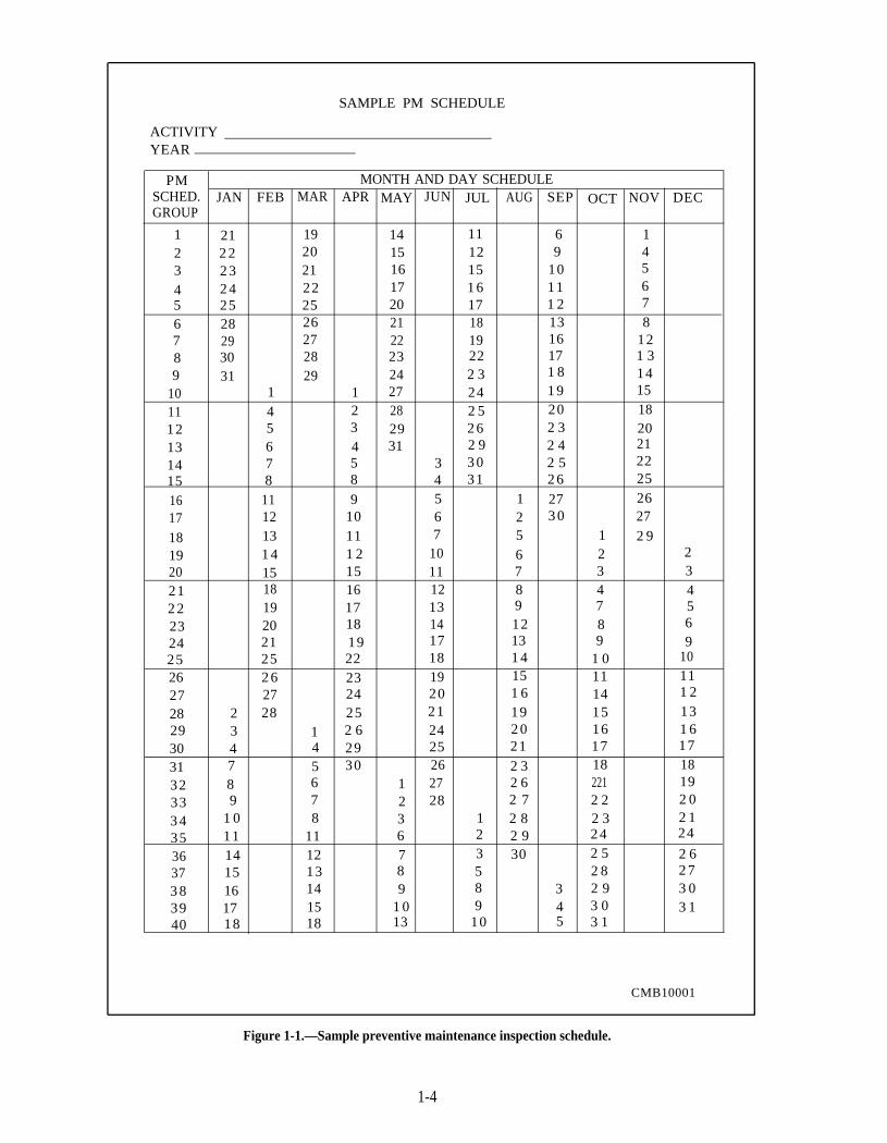
Figure 1-1.—Sample preventive maintenance inspection schedule.
1-4
group and so on. The equipment should be grouped so aunit that works together is scheduled for the same PMgroup; for example, semitrailers with truck tractors,scrapers with tractors, and so on. Activities shouldassign each piece of equipment to one PM groupinitially. After the system is established and operating,the maintenance supervisor should review itseffectiveness and REDUCE the intervals for highmileage/hour items of equipment, if necessary. Thetime interval is NEVER INCREASED beyond 40working days.
Preventive Maintenance
A preventive maintenance inspection schedule,such as the one shown in figure l-l, should beestablished annually. A new schedule is required eachyear, as the schedules are based on the workdays in eachcalendar year. The workdays on the schedule mustcorrespond to the actual workdays of the unit; forexample, if you work a 5-day week, enter 5 days; omitholidays. The PM groups are numbered vertically downthe first column. Figure 1-1 shows the standard 40 PMgroup concept arranged for a 5-day workweek. Thedates of the workdays of January are then listedconsecutively in the January column. After the lastworkday in January is entered, continue with workdaysin the February column and so forth. After completion,the schedule indicates the workdays that each PM groupis due for inspection. For example, figure 1-1 showsPM group 5 is due on January 8, March 6, May 1, June27, August 23, October 23, and December 19.
OPERATOR'S INSPECTION GUIDE AND TROUBLE REPORT
REGISTRATION NO. ODOMETER READING
94-75111 7581Use this form as a guide when performing before and after operationinspection. Check items that require servicing by maintenancepersonnel.
1. DAMAGE (Exterior, Interior, Missing Components)
2 . L E A K S ( O i l , G a s , W a t e r )
3. T I R E S ( C h e c k I n f l a t i o n , a b n o r m a l w e a r )
4. F U E L , O I L , W A T E R S U P P L Y ( A n t i f r e e z e i n s e a s o n )
5. B A T T E R Y ( C h e c k w a t e r l e v e l , c a b l e s , e t c . )
6. HORN
7. LIGHTS/REFLECTORS/MIRRORS/TURN SIGNALS
8. INSTRUMENTS (Oil, Air, Temperature, etc.)
9. WINDSHIELD WIPER
10. C L E A N W I N D S H I E L D / V E H I C L E I N T E R I O R
11. CARGO, MOUNTED EQUIPMENT
12. S T E E R I N G
13. S A F E T Y D E V I C E S ( S e a t b e l t s , f l a r e s , e t c . )
14. DRIVE BELTS/PULLEYS
15. B R A K E S ( D r a i n a i r t a n k w h e n e q u i p p e d )
16. O T H E R ( S p e c i f y i n " R e m a r k s " )
DATE OPERATOR'S SIGNATURE
01 Jul 1997REMARKS
OIL LEAK BOTTOM OF OIL PAN
N A V F A C 9 - 1 1 2 4 0 1 3 ( 1 2 - 8 9 )
Supersedes DD Form 1358 *U.S. Government Printing Office: 1983 683-006-1060S/N 0105-LF-004-1195
CMB10002
MAINTENANCE INSPECTIONS
The object of a maintenance inspection is to detectminor deficiencies before they develop into costlymajor repairs. This is done daily by the operator andregularly scheduled preventive maintenance.
Operator
The first sign of vehicle trouble is usually detectedby the operator during one of the three daily inspections:before, during, and after operation.
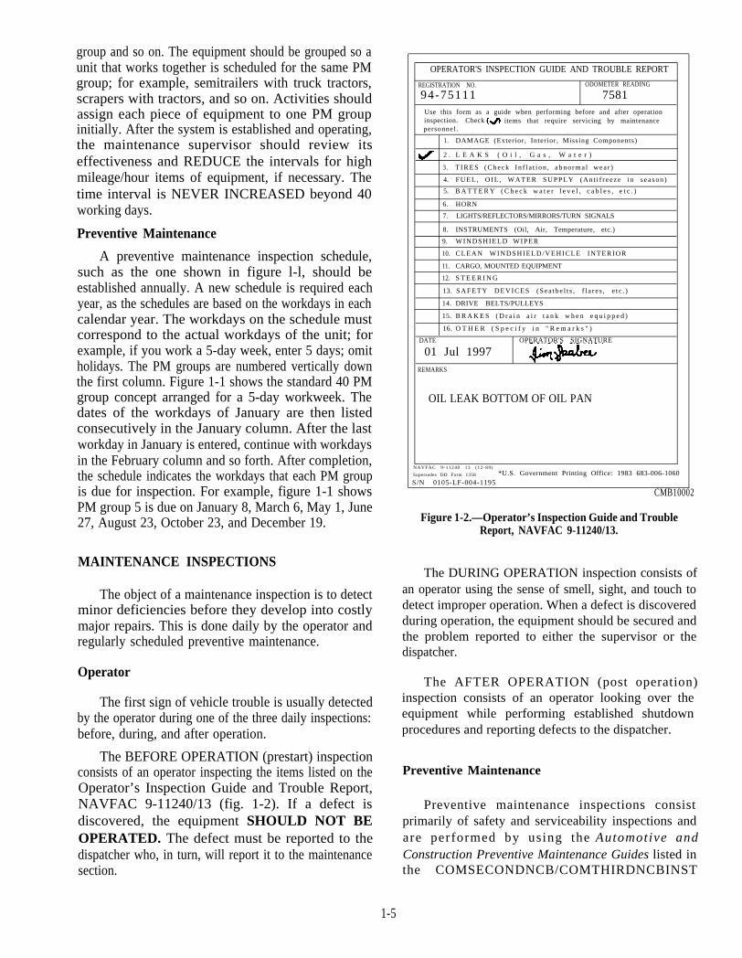
The BEFORE OPERATION (prestart) inspectionconsists of an operator inspecting the items listed on theOperator’s Inspection Guide and Trouble Report,NAVFAC 9-11240/13 (fig. 1-2). If a defect isdiscovered, the equipment SHOULD NOT BEOPERATED. The defect must be reported to thedispatcher who, in turn, will report it to the maintenancesection.
Figure 1-2.—Operator’s Inspection Guide and TroubleReport, NAVFAC 9-11240/13.
The DURING OPERATION inspection consists ofan operator using the sense of smell, sight, and touch todetect improper operation. When a defect is discoveredduring operation, the equipment should be secured andthe problem reported to either the supervisor or thedispatcher.
The AFTER OPERATION (post operation)inspection consists of an operator looking over theequipment while performing established shutdownprocedures and reporting defects to the dispatcher.
Preventive Maintenance
Preventive maintenance inspections consistprimarily of safety and serviceability inspections andare performed by using the Automotive andConstruction Preventive Maintenance Guides listed inthe COMSECONDNCB/COMTHIRDNCBINST
1-5
11200.1. The type of PM inspection is determined andcontrolled as follows:
Type "A" (01)—At intervals of 40 working days.It is performed on each scheduled PM due dateuntil a vehicle qualifies for a type "B" PM.
Type "B" (02)—PMs are based on the equipmentm a n u f a c t u r e r ’ s r e c o m m e n d a t i o n s /specifications for milage/hours usage required toinitiate a "B" (02) for fluid and filter change,major adjustments or scheduled maintenance asrequired. For example, a 5-ton dump truckcould undergo three or four "A" (01) PMs beforeaccumulating the required milage/hours for a"B" (02) PM.
Type "C" (03)—Annual safety inspection (ASI),as per manufacturer’s recommendations/specifications.
Deadline Vehicle
Deadline inspections are particularly critical toensure equipment does not deteriorate. Deadlineinspections are performed at each regularly scheduledPM. An 01 level PM is accomplished on all deadlineCESE. The equipment is inspected to ensure thefollowing:
All openings are covered and weathertight.
All machined surfaces are preserved.
All disassembled components are tagged,covered, and stored.
No cannibalization has taken place since the lastinspection (controlled parts interchange is notapproved as a normal procedure; however, themaintenance supervisor only may authorize it tomeet operational commitments).
Parts removed from deadline equipment shouldbe replaced with non-serviceable items, and themaintenance supervisor must ensure thatreplacement parts are ordered "NotOperationally Ready for Supply (NORS)." Thisshould be done using a priority applicable tomission accomplishment.
All replacement parts, costs, and labor hoursrelated to the interchange should be chargedagainst the item of equipment on which the partfailed. When the replacement parts are received
1-6
and installed, only the labor involved should becharged to the piece of equipment from whichthe interchange part was taken.
Whenever possible, deadline inspections shouldinclude cycling (checking components for properoperation). For example, if a truck is deadlined for anaxle, you can still start the engine and ensure that it runsproperly. When cycling is accomplished, make surethat all required preservation is accomplished.Equipment is considered deadlined when it does notperform as designed or when it is in need of parts that arenot on hand.
Accident
Accident safety inspections "12" ERO are initiatedon all CESE involved in a mishap, regardless of damageand is commonly used for estimates. This inspectionensures that a vehicle is in safe condition before beingreleased for operation Any repairs and parts requiredmust be charged against this Equipment Repair Order(ERO). No preventive maintenance should beperformed. When preventive maintenance is required,the type "12" ERO should be closed and another EROopened for the maintenance required.
PM RECORD CARDS
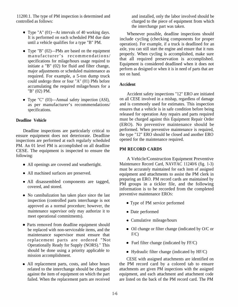
A Vehicle/Construction Equipment PreventiveMaintenance Record Card, NAVFAC 11240/6 (fig. 1-3)must be accurately maintained for each item of assignedequipment and attachments to assist the PM clerk inpreparing an ERO. PM record cards are maintained byPM groups in a tickler file, and the followinginformation is to be recorded from the completedpreventive maintenance EROS:
Hydraulic filter change (indicated by HF/C)
Fuel filter change (indicated by FF/C)
Oil change or filter change (indicated by O/C orF/C)
Cumulative mileage/hours
Date performed
Type of PM service performed
CESE with assigned attachments are identified onthe PM record card by a colored tab to ensureattachments are given PM inspections with the assignedequipment, and each attachment and attachment codeare listed on the back of the PM record card. The PM
Figure 1-3.—Vehicle/Construction Equipment PM Record Card, NAVFAC Form 11240/6.
1-7
record cards are returned to the equipment historyjacket whenever CESE is transferred or the card is full.
REPAIR ORDERS
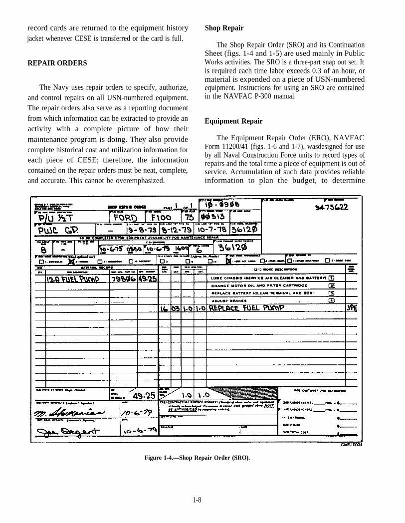
The Navy uses repair orders to specify, authorize,and control repairs on all USN-numbered equipment.The repair orders also serve as a reporting documentfrom which information can be extracted to provide anactivity with a complete picture of how theirmaintenance program is doing. They also providecomplete historical cost and utilization information foreach piece of CESE; therefore, the informationcontained on the repair orders must be neat, complete,and accurate. This cannot be overemphasized.
Shop Repair
The Shop Repair Order (SRO) and its ContinuationSheet (figs. 1-4 and 1-5) are used mainly in PublicWorks activities. The SRO is a three-part snap out set. Itis required each time labor exceeds 0.3 of an hour, ormaterial is expended on a piece of USN-numberedequipment. Instructions for using an SRO are containedin the NAVFAC P-300 manual.
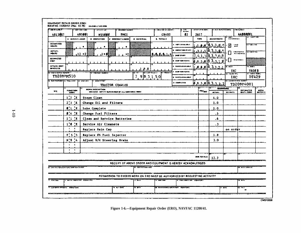
Equipment Repair
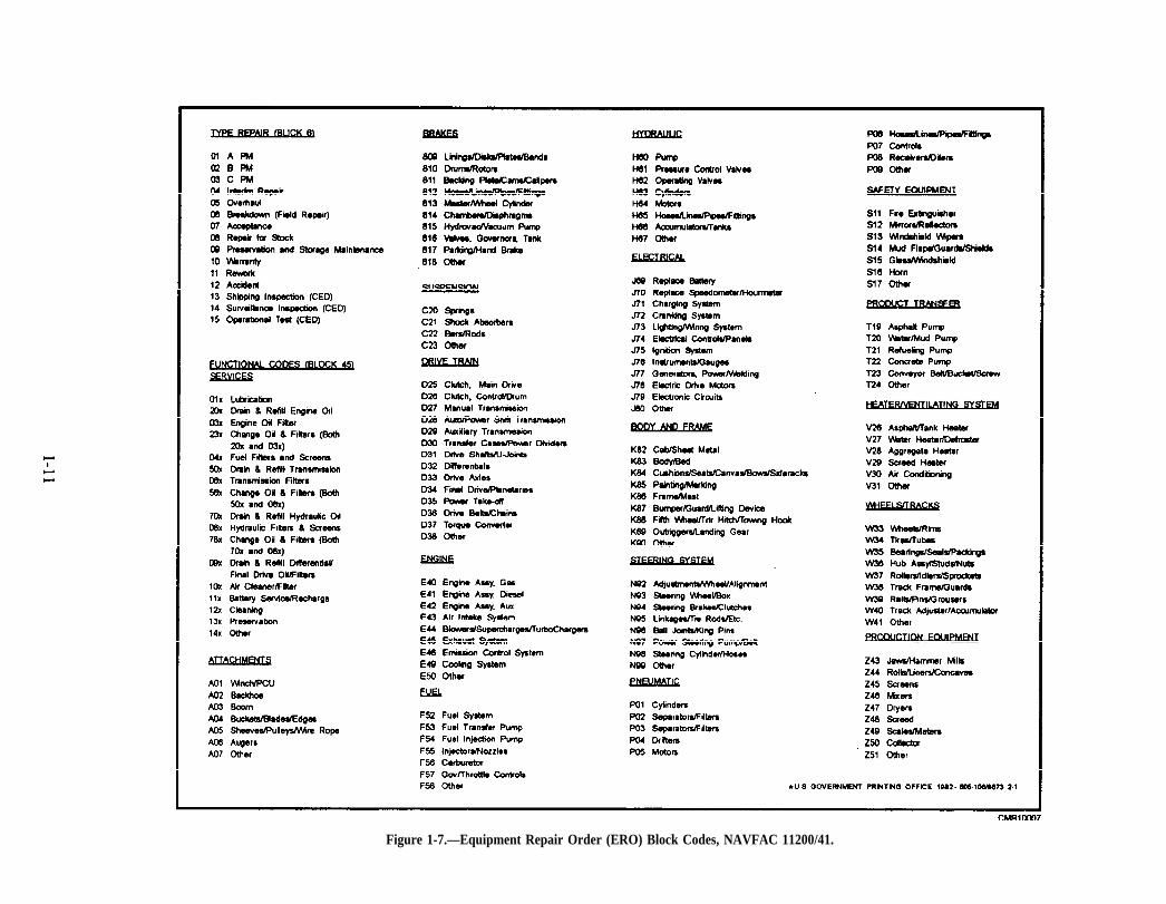
The Equipment Repair Order (ERO), NAVFACForm 11200/41 (figs. 1-6 and 1-7). wasdesigned for useby all Naval Construction Force units to record types ofrepairs and the total time a piece of equipment is out ofservice. Accumulation of such data provides reliableinformation to plan the budget, to determine
Figure 1-4.—Shop Repair Order (SRO).
1-8
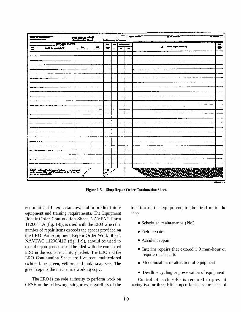
Figure 1-5.—Shop Repair Order Continuation Sheet.
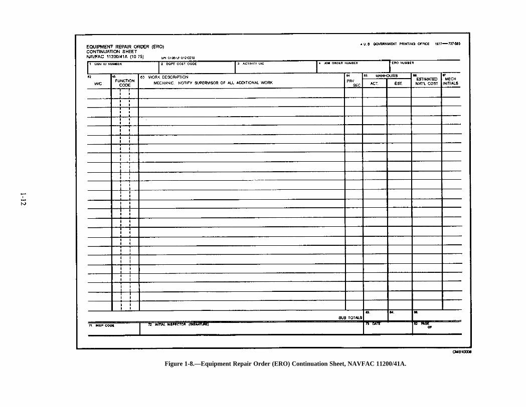
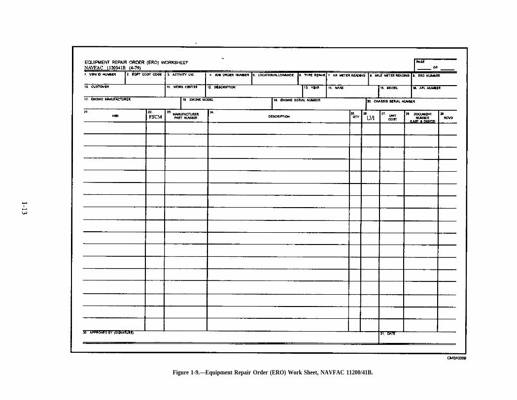
economical life expectancies, and to predict futureequipment and training requirements. The EquipmentRepair Order Continuation Sheet, NAVFAC Form11200/41A (fig. 1-8), is used with the ERO when thenumber of repair items exceeds the spaces provided onthe ERO. An Equipment Repair Order Work Sheet,NAVFAC 11200/41B (fig. 1-9), should be used torecord repair parts use and be filed with the completedERO in the equipment history jacket. The ERO and theERO Continuation Sheet are five part, multicolored(white, blue, green, yellow, and pink) snap sets. Thegreen copy is the mechanic's working copy.
The ERO is the sole authority to perform work onCESE in the following categories, regardless of the
location of the equipment, in the field or in theshop:
Scheduled maintenance (PM)
Field repairs
Accident repair
Interim repairs that exceed 1.0 man-hour orrequire repair parts
Modernization or alteration of equipment
Deadline cycling or preservation of equipment
Control of each ERO is required to preventhaving two or three EROS open for the same piece of
1-9
Page 1-10
Figure 1-6.—Equipment Repair Order (ERO), NAVFAC 11200/41.
Page 1-11
Figure 1-7.—Equipment Repair Order (ERO) Block Codes, NAVFAC 11200/41.
Page 1-12
Figure 1-8.—Equipment Repair Order (ERO) Continuation Sheet, NAVFAC 11200/41A.
Page 1-13
Figure 1-9.—Equipment Repair Order (ERO) Work Sheet, NAVFAC 11200/41B.
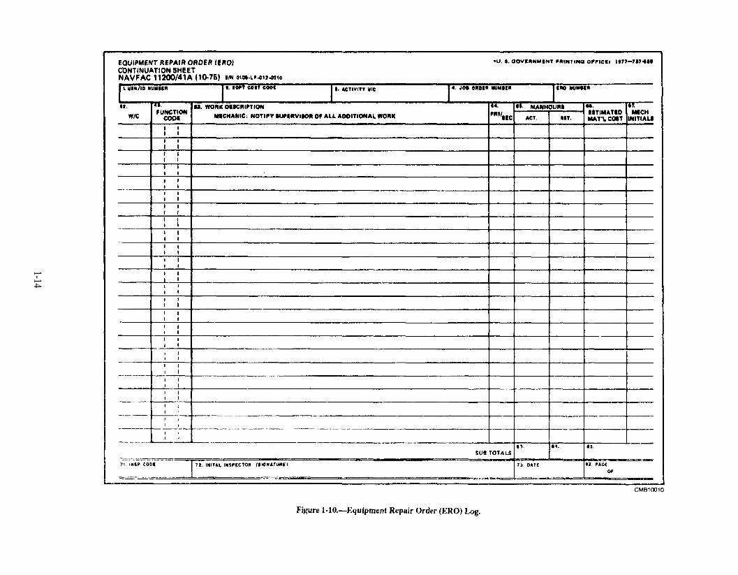
Figure 1-10.
1-14
equipment. Figure 1-10 shows a sample EquipmentRepair Order Log. The types of information generallycalled for are the following:
ERO number (assigned eight-digit number).(The first four digits are two alpha characters andtwo numeric, such as AA00. The last four digitsare numeric and constitute a Job SequenceNumber (JSN) which is assigned locally. ThisJSN runs continuously from 0001 through 9999.At such time as 9999 is used, a new series starts0001.)
Equipment code (six-digit code, as shown on thePM record card).
USN number (seven digit equipment registrationnumber).
Type of repair (type of maintenance performed,such as 01, 02, or 03).
Date in (date ERO forwarded to inspector).
Date out (date equipment is returned todispatch).
PM group.
Hard card number (number issued by dispatchfrom the hard card log).
Remarks (date deadlined, and so on).
The EROS and the ERO log are maintained by the PMclerk. Complete instructions on the use of EROS arelocated in the Management of Civil EngineeringSupport Equipment, P-300, and the COM-SECONDNCB/COMTHIRDNCBINST 11200.1.
EQUIPMENT HISTORY JACKETS
An equipment history jacket is maintained for eachUSN-numbered piece of CESE. The history jacketcontains the pertinent descriptive data and maintenancehistory of the vehicle. The descriptive data includes theappropriate DoD Property Record, DD Form 1342 (fig.1-11), and Equipment Attachment Registration Record,NAVFAC 6-11200/45 (fig. 1-12), if applicable. Themaintenance history jacket also includes the completedPM record cards and blue copies of completed EROS.
When a vehicle is transferred, the PM record card isremoved from the PM group file and returned to thehistory jacket. The jacket is then either hand carried orforwarded by mail to the receiving custodian. When
the vehicle is to be transferred to a DefenseReutilization Marketing Office (DRMO), the historyjacket must accompany it.
LABOR REPORTING
In battalions and at shore-based activites, yourduties involve posting of working hours on time cardsfor military personnel; therefore, you should know thetype of information required in labor reporting. Youshould note that the labor reporting system usedprimarily in Naval Mobile Construction Battalions(NMCBs) and the system used at a shore-based activityare similar.
A labor accounting system is mandatory for you torecord and measure the number of man-hours that a unitspends on various functions. In this system, labor usagedata is collected daily in sufficient detail and in a waythat enables the Operations Department to compile thedata readily and prepare reports for higher authority.
Although labor accounting systems vary slightlyfrom one command to another, the system describedhere can be tailored to record labor at any command.
A unit must account for all the labor used to carryout its assignment. Labor costs are figured and actualman-hours are compared with previous estimates basedon jobs of a similar nature. When completed, thisinformation is used by unit managers and highercommands to develop planning standards.
The labor accounting system covered in this sectionis based upon the procedure and guidelines establishedby both Naval Construction Brigades (NCBs) forNMCB use.
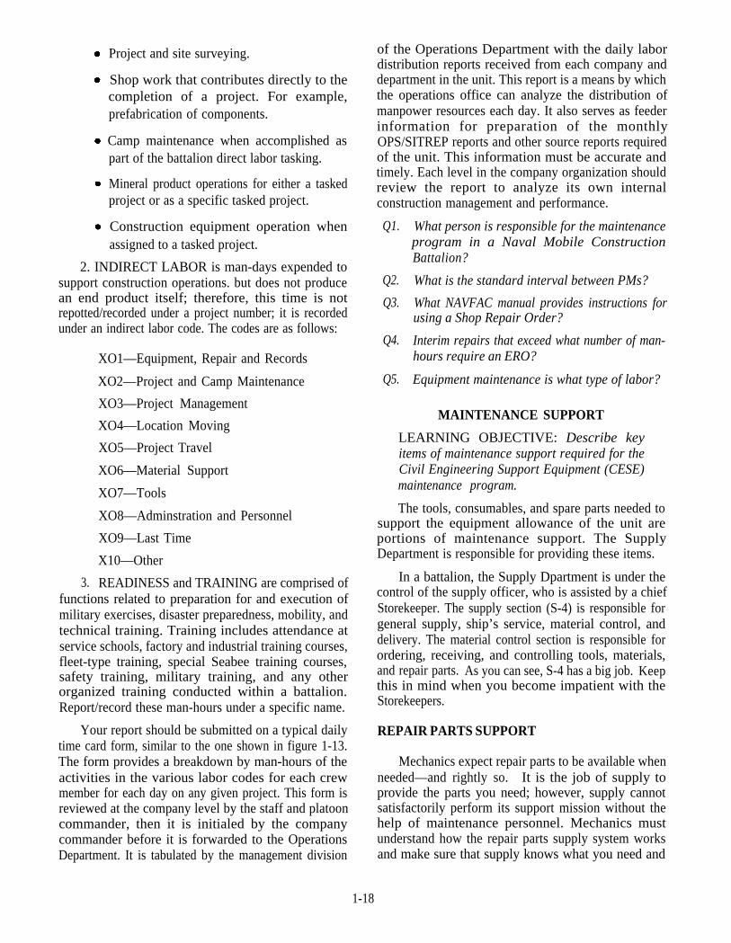
Time cards (fig. 1-13) are the basis for yoursituation report (SITREP) input. Therefore, it isimperative that time cards be filled out correctly andaccurately. COMSECONDNCB/COMTHRIDNCB-INST5312.1 is the instruction that governs timekeepingprocedures. Man-hours should be recorded under aspecific code in one of three labor categories. Thecategories are listed below.
1. DIRECT LABOR is man-days expendeddirectly on assigned construction activity, either in thefield or in the shop, and labor that contributes directly tothe completion of an end product. Tasked projects areassigned a project number. Labor expended on aspecific project should be reported under that projectnumber. Record direct labor by construction activitynumber. Included under direct labor (besidesconstruction) arc such tasks as the following:
1-15
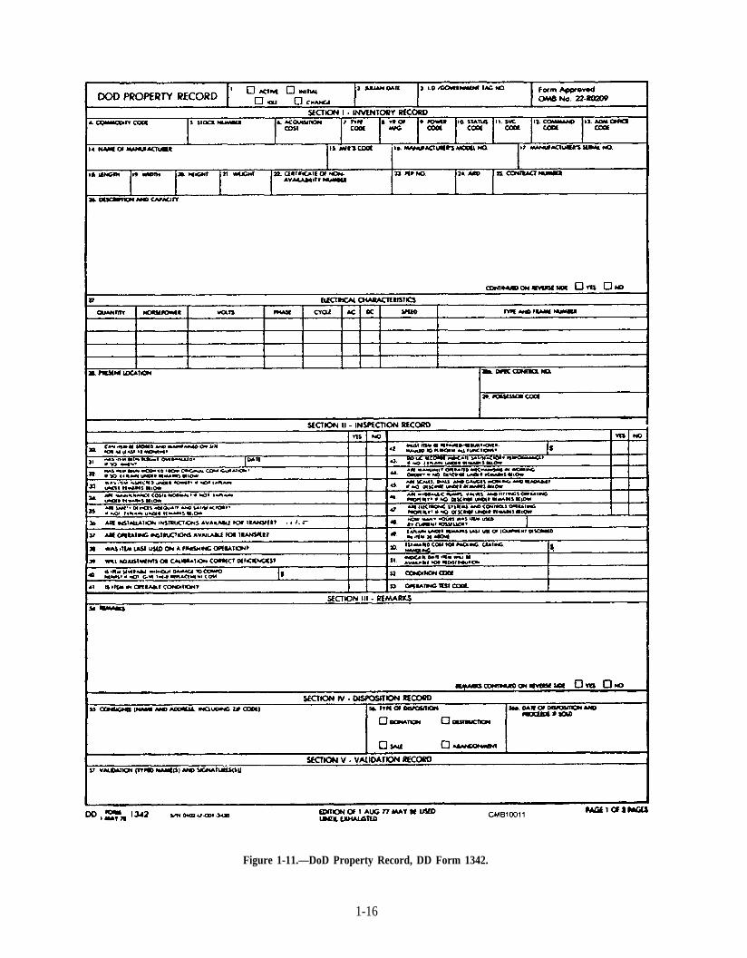
Figure 1-11.—DoD Property Record, DD Form 1342.
1-16
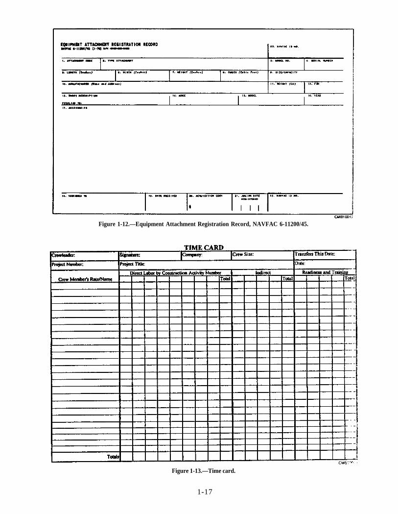
Figure 1-12.—Equipment Attachment Registration Record, NAVFAC 6-11200/45.
Figure 1-13.—Time card.
1-17
Shop work that contributes directly to thecompletion of a project. For example,prefabrication of components.
Project and site surveying.
Camp maintenance when accomplished aspart of the battalion direct labor tasking.
Mineral product operations for either a taskedproject or as a specific tasked project.
Construction equipment operation whenassigned to a tasked project.
2. INDIRECT LABOR is man-days expended tosupport construction operations. but does not producean end product itself; therefore, this time is notrepotted/recorded under a project number; it is recordedunder an indirect labor code. The codes are as follows:
XO1—Equipment, Repair and Records
XO2—Project and Camp Maintenance
XO3—Project Management
XO4—Location Moving
XO5—Project Travel
XO6—Material Support
XO7—Tools
XO8—Adminstration and Personnel
XO9—Last Time
X10—Other
3. READINESS and TRAINING are comprised offunctions related to preparation for and execution ofmilitary exercises, disaster preparedness, mobility, andtechnical training. Training includes attendance atservice schools, factory and industrial training courses,fleet-type training, special Seabee training courses,safety training, military training, and any otherorganized training conducted within a battalion.Report/record these man-hours under a specific name.
Your report should be submitted on a typical dailytime card form, similar to the one shown in figure 1-13.The form provides a breakdown by man-hours of theactivities in the various labor codes for each crewmember for each day on any given project. This form isreviewed at the company level by the staff and platooncommander, then it is initialed by the companycommander before it is forwarded to the OperationsDepartment. It is tabulated by the management division
of the Operations Department with the daily labordistribution reports received from each company anddepartment in the unit. This report is a means by whichthe operations office can analyze the distribution ofmanpower resources each day. It also serves as feederinformation for preparation of the monthlyOPS/SITREP reports and other source reports requiredof the unit. This information must be accurate andtimely. Each level in the company organization shouldreview the report to analyze its own internalconstruction management and performance.
Q1. What person is responsible for the maintenanceprogram in a Naval Mobile ConstructionBattalion?
Q2. What is the standard interval between PMs?
Q3. What NAVFAC manual provides instructions forusing a Shop Repair Order?
Q4. Interim repairs that exceed what number of man-hours require an ERO?
Q5. Equipment maintenance is what type of labor?
MAINTENANCE SUPPORT
LEARNING OBJECTIVE: Describe keyitems of maintenance support required for theCivil Engineering Support Equipment (CESE)maintenance program.
The tools, consumables, and spare parts needed tosupport the equipment allowance of the unit areportions of maintenance support. The SupplyDepartment is responsible for providing these items.
In a battalion, the Supply Dpartment is under thecontrol of the supply officer, who is assisted by a chiefStorekeeper. The supply section (S-4) is responsible forgeneral supply, ship’s service, material control, anddelivery. The material control section is responsible forordering, receiving, and controlling tools, materials,and repair parts. As you can see, S-4 has a big job. Keepthis in mind when you become impatient with theStorekeepers.
REPAIR PARTS SUPPORT
Mechanics expect repair parts to be available whenneeded—and rightly so. It is the job of supply toprovide the parts you need; however, supply cannotsatisfactorily perform its support mission without thehelp of maintenance personnel. Mechanics mustunderstand how the repair parts supply system worksand make sure that supply knows what you need and
1-18
when you need it. Telling supply you need a"whatchamacallit" for a jeep does not help, but providethem the proper nomenclature and a part number andthey can obtain it for you. Normally at least onemechanic is assigned to the repair parts storeroom fortechnical information and assistance. The DTO clerkprovides liaison with supply for checking requisitionstatus. The maintenance supervisor assists supply indetermining additional repair parts requirements. TheNCF initial outfitting of repair parts is designed tosupport new or like-new CESE for the first 1,200construction hours. It is based on two 10-hour shifts, 7days per week, for the first 60 days of deployment.
Levels
There are four different levels of repair partssupport (O, G, H, or D) that can be assigned to a unit,depending upon its mission, location, maintenancecapabilities, and so on.
1.
2.
3.
4.
"O" LEVEL support is designed for Seabeeteams, Construction Battalion Units (CBUs),Reserve battalions, and outlying NMCBs thatperform only organizational level maintenance.It is the lowest level of support.
"G" LEVEL support is designed forNMCB/PHIBCB major detachments thatperform intermediate level maintenance.
"H" LEVEL support is designed for the mainbody of an NMCB/PHIBCB that performsintermediate level maintenance.
"D" LEVEL support is designed for major shops(CBCs) that perform depot level maintenance.
Each level of support includes all lower level items;for example, "H" level includes all "O" and "G" levelitems.
Categories of Repair Parts
Repair parts can be divided into two categories:parts peculiar and parts common.
REPAIR PARTS PECULIAR is composed of partsthat only fit a specific make and model piece ofequipment. When a unit requests support for anallowance of equipment, the Civil Engineering SupportOffice (CESO) identifies the applicable AllowanceParts List (APL) for each make and model of equipmentin the allowance. Using the APLs that are identified byCESO, the Ships Parts Control Center (SPCC)consolidates these APLs into a tailored repair parts list.
This list is referred to as a Consolidated SeabeeAllowance List (COSAL) or a NAVSUP Modifier Code98 (MOD 98 kit). CESO provides copies of the COSALto both the requesting unit and the ConstructionBattalion Center (CBC) that supports it. The CBC isthen responsible for drawing the required items fromstock or initiating procurement action and shipping theparts to the unit requesting the allowance.
REPAIR PARTS COMMON is composed ofcommon and consumable supplies for use on numeroustypes of equipment. These items have been separatedinto common assemblies (MOD 97 kit) to reduceredundancy and overstocking of these items. Presentlythe MOD 97 kit consists of 29 individual kits, such ashydraulic hose and fittings, nuts and bolts, electricalterminals and wire, O rings, and so on. The MOD 97 kitis designed to supplement a MOD 98 kit for the first 60days of a contingency operation. Note that these MOD97 kits are not designed to support a unit for a fulldeployment. MOD 96 provided the same support forsmaller units such as details and air detachments.
COSAL Arrangement
Each COSAL is arranged and divided into threeseparate parts.
PART I consists of a cross-reference list todetermine what APL applies to what USN number.PART I is composed of three separate cross-referencelists, each containing the same information, but sortedand printed in a different sequence.
Section A is printed in USN-number sequence.
Section B is in Equipment Code (EC) sequence.
Section C is in APL-number sequence.
PART II consists of APLs arranged byidentification number. The APL identification numberis listed in both the upper- and lower-right corner ofeach APL page and consists of nine digits, such as950004121. The PART II MAJOR SEQUENCE isbased on the last four digits (950004121) of the APLidentification number (low to high). This is commonlyreferred to as the APL number. Exceptions are vehicles,such as truck-mounted water distributors (one APL forthe truck, another APL for the distributor) and mobilecranes (one APL for the carrier, another for the crane.)The PART II MINOR SEQUENCE is based on thepreceding three digits, such as 950064121 for the fuelsystem group items. A listing of groups covered in eachAPL is displayed on the first page of each APL, such as
1-19

950004121. The first two digits of the APL number used by the NCF. The first CID group is always(950004121) are consistent in the Naval Construction the allowance application group. The second CIDForce COSALs because they identify the APL as NCF group is the technical manual group that lists allversus shipboard Within each APL, the parts are the applicable operating, maintenance, and partsarranged by component identification groups (CIDs). manuals. The remainder of the AFXs contain actualFigure 1-14 shows the CID groups presently being parts listings.
CID Group Name CID Group Name
000OTM001002003004005006007008009010011012013014015016017018019020021022023024025026027028029030031032033034035036037038039040041042
Allowance Application Group (Gp) 043Technical Manual Gp 044Engine GpTruck Engine GpStarting Engine GpAuxiliary Engine GpClutch GpFuel System GpExhaust System GpCooling System GpElectrical System GpTransmission GpAuxiliary Transmission GpPower Transfer GpPropeller Shaft GpFront Axle GpRear Axle GpBrakes GpWheels GpTracks GpSteering GpFrame GpSprings/Shock Absorbers GpBody, Cab, Hood, Hull GpHoists GpPower Control Unit GpPower Take Off GpMiscellaneous Body GpElevator GpElectric Motors GpElectric Generators GpElectrical Equipment GpHydraulic Systems GpAir and Vacuum Systems GpGage and Measuring Devices GpPneumatic Equipment GpPump GpBurner GpMach Tools/Related Equip GpSnow Removal Equipment GpMowing/Sweeping Equipment GpServicing Equipment GpConcrete/Asphalt Equipment GpCrane/and/or Shovel Gp
045046047048049050051052053054055056057058059060061062063064065066067068069070071072073074075076077078079080081082083085086087
Grader GpDoze r GpDitcher or Trencher GpRoad Roller GpEarth Auger Truck Mounted GpConveying Equipment GpCrushing Equipment GpScreening/Washing Equip. GpFire Fighting Equipment GpRefrigeration/Acng GpMMK GpSeparator GpRunning Gear GpManifold GpTank GpTrailer GpFlood Light GpFi l ter or St ra iner GpChlorine Control GpEvaporating GpWater Fording GpMachinery GpLaundry Equipment GpWinterization GpBobsled GpDolly GpGenerator Lox & Nitrogen GpSteam Cleaning GpSpraying Equipment GpSaw GpDistillation Equipment GpHeater Gp (Gas or Fuel)Blower GpBoiler GpPile Driver GpWater Purification GpReel GpScraper GpRipper GpOutboard Drive GpRotary Tiller Soil Stabilizer GpDrill Equipment (Pneu) GpDehydrator GpRemote Control Gp
CMB10014
Figure 1-14.—Component identification group numbers (CIDs).
1-20
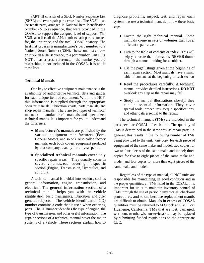
PART III consists of a Stock Number Sequence List(SNSL) and two repair parts cross lists. The SNSL liststhe repair parts, arranged in National Item IdentificationNumber (NIIN) sequence, that were provided in theCOSAL to support the assigned level of support TheSNSL also lists all the APL numbers each part is stockedfor, the unit price, and the total COSAL quantity. Thefirst list crosses a manufacturer's part number to aNational Stock Number (NSN). The second list crossesan NSN, in NIIN sequence, to a part number. Part III isNOT a master cross reference; if the number you areresearching is not included in the COSAL, it is not inthese lists.
Technical Manuals
One key to effective equipment maintenance is theavailability of authoritative technical data and guidesfor each unique item of equipment. Within the NCF,this information is supplied through the appropriateoperator manuals, lubrication charts, parts manuals, andshop repair manuals. There are two types of technicalmanuals: manufacturer’s manuals and specializedtechnical mantis. It is important for you to understandthe difference.
Manufacturer’s manuals are published by thevarious equipment manufacturers (Ford,General Motors, and so on). Also called factorymanuals, each book covers equipment producedby that company, usually for a l-year period.
Specialized technical manuals cover onlyspecific repair areas. They usually come inseveral volumes, each covering one specificsection (Engine, Transmission, Hydraulics, andso forth).
A technical manual is divided into sections, such asgeneral information, engine, transmission, andelectrical. The general information section of atechnical manual helps you with the vehicleidentification, basic maintenance, lubrication, and othergeneral subjects. The vehicle identification (ID)number contains a code that is used when orderingparts. The ID number identifies the type of engine, thetype of transmission, and other useful information Therepair sections of a technical manual cover the majorsystems of a vehicle. These sections explain how to
diagnose problems, inspect, test, and repair eachsystem. To use a technical manual, follow these basicsteps:
Locate the right technical manual. Somemanuals come in sets or volumes that coverdifferent repair areas.
Turn to the table of contents or index. This willhelp you locate the information. NEVER thumbthrough a manual looking for a subject.
Use the page listings given at the beginning ofeach repair section. Most manuals have a smalltable of contents at the beginning of each section
Read the procedures carefully. A technicalmanual provides detailed instructions. DO NOToverlook any step or the repair may fail.
Study the manual illustrations closely; theycontain essential information. They coverspecial tools, procedures, torque specifications,and other data essential to the repair.
The technical manuals (TMs) are included in theparts peculiar COSAL of each unit. The quantity ofTMs is determined in the same way as repair parts. Ingeneral, this results in the following number of TMsbeing provided to the unit: one copy for each piece ofequipment of the same make and model; two copies fortwo to four pieces of the same make and model; threecopies for five to eight pieces of the same make andmodel; and four copies for more than eight pieces of thesame make and model.
Regardless of the type of manual, all NCF units areresponsible for maintaining, in good condition and inthe proper quantities, all TMs listed in the COSAL. It isimportant for units to maintain inventory control ofTMs through the use of periodic inventories, check-outprocedures, and so on, because replacement mantisare difficult to obtain. Manuals in excess of COSALquantities must be returned to M3 stock at CBC, PortHueneme, California. TMs that are lost, damaged,worn out, or otherwise unserviceable, may be replacedby submitting funded requisitions to the appropriateCBC.
1-21
REQUESTING SPARE PARTS
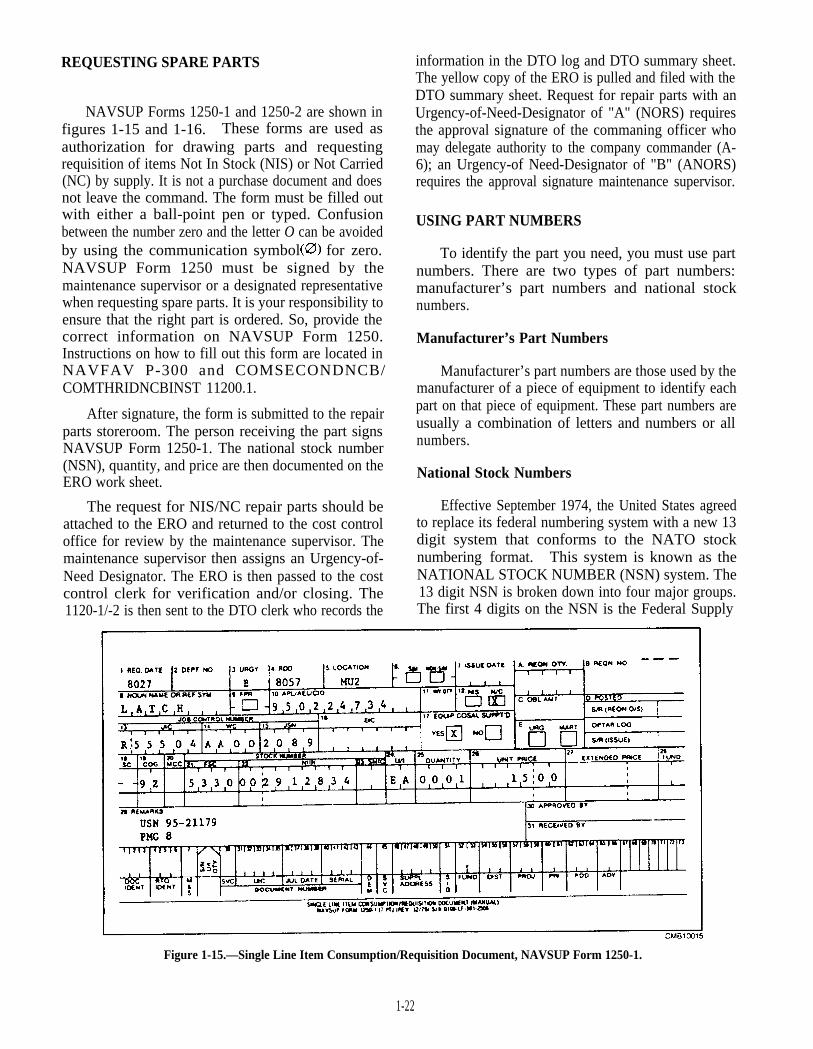
NAVSUP Forms 1250-1 and 1250-2 are shown infigures 1-15 and 1-16. These forms are used asauthorization for drawing parts and requestingrequisition of items Not In Stock (NIS) or Not Carried(NC) by supply. It is not a purchase document and doesnot leave the command. The form must be filled outwith either a ball-point pen or typed. Confusionbetween the number zero and the letter O can be avoidedby using the communication symbol for zero.NAVSUP Form 1250 must be signed by themaintenance supervisor or a designated representativewhen requesting spare parts. It is your responsibility toensure that the right part is ordered. So, provide thecorrect information on NAVSUP Form 1250.Instructions on how to fill out this form are located inNAVFAV P-300 and COMSECONDNCB/COMTHRIDNCBINST 11200.1.
information in the DTO log and DTO summary sheet.The yellow copy of the ERO is pulled and filed with theDTO summary sheet. Request for repair parts with anUrgency-of-Need-Designator of "A" (NORS) requiresthe approval signature of the commaning officer whomay delegate authority to the company commander (A-6); an Urgency-of Need-Designator of "B" (ANORS)requires the approval signature maintenance supervisor.
USING PART NUMBERS
To identify the part you need, you must use partnumbers. There are two types of part numbers:manufacturer’s part numbers and national stocknumbers.
Manufacturer’s Part Numbers
After signature, the form is submitted to the repairparts storeroom. The person receiving the part signsNAVSUP Form 1250-1. The national stock number(NSN), quantity, and price are then documented on theERO work sheet.
Manufacturer’s part numbers are those used by themanufacturer of a piece of equipment to identify eachpart on that piece of equipment. These part numbers areusually a combination of letters and numbers or allnumbers.
National Stock Numbers
The request for NIS/NC repair parts should be Effective September 1974, the United States agreedattached to the ERO and returned to the cost control to replace its federal numbering system with a new 13office for review by the maintenance supervisor. The digit system that conforms to the NATO stockmaintenance supervisor then assigns an Urgency-of- numbering format. This system is known as theNeed Designator. The ERO is then passed to the cost NATIONAL STOCK NUMBER (NSN) system. Thecontrol clerk for verification and/or closing. The 13 digit NSN is broken down into four major groups.1120-1/-2 is then sent to the DTO clerk who records the The first 4 digits on the NSN is the Federal Supply
Figure 1-15.—Single Line Item Consumption/Requisition Document, NAVSUP Form 1250-1.
1-22
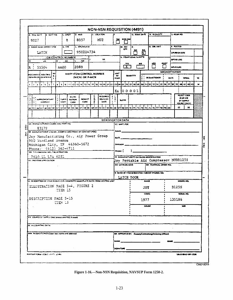
Figure 1-16.—Non-NSN Requisition, NAVSUP Form 1250-2.
1-23
Classification (FSC) that groups similar items intoclasses. The last 9 digits of the NSN is the National ItemIdentification Number (NIIN). The first 2 digits of theNIIN identifies the NATO country that cataloged theitem, and the last 7 digits identifies the item.
As pointed out above, NSN numbers provide youwith the federal class of the item (first 4 digits), whatcountry cataloged the item (digits 5 and 6). and the itemidentification number (last 7 digits).
Part III of the COSAL is the section used to cross-reference manufacturer’s part numbers to NSNs.
REPAIR PARTS CONTROL
Each maintenance department is required tomaintain control over repair parts. One of the biggestproblems in some maintenance programs is the controlof direct turnover (DTO) repair parts. DTO parts arethose ordered for direct turnover to the user.
For DTO parts to be complete and accurate, allNAVSUP Form 1250s for NIS and NC repair parts mustpass through the cost control clerk and the DTO clerkbefore being submitted to the supply office. The supplyoffice maintains current procurement and shippingstatus for items on order. When requesting the status ofa requisition from supply, DTO clerks must be able toidentify, by requisition number, the procurementdocument they are interested in. Accurate DTO partsrecords accomplish this and allow the cost control clerkto identify the USN-number of the equipment each partwas ordered for. The DTO repair parts status keepingsystem provides excellent accountability withminimum effort. This system consists of two separaterecords designed to be used together: the DTO log andthe repair parts summary sheets.
DTO Log
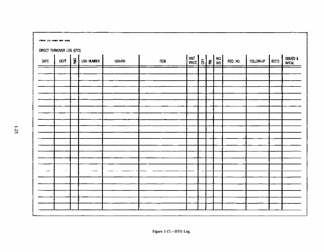
The DTO log (fig. 1-17) is a sequential record andproof of order for all NAVSUP Form 1250-1/-2 requestsfor NIS/NC/Non-NSN requirements submitted to therepair parts storeroom. It is maintained in such a waythat the last NAVSUP Form 1250 entered is the last partsrequest submitted to the supply office. This tells theDTO clerk when the requisition was submitted tosupply. Normally, supply should order priority "A"(NORS) requisitions within 24 hours and priority "B"and "C" requisitions within 7 days. Afteraccomplishing all ordering actions and issuing aprocurement document, supply enters the requisitionnumber in block "B" of a NAVSUP Form 1250-1 orblock "I" of a NAVSUP Form 1250-2. The pink copy is
returned to the repair parts storeroom whereoutstanding requisition data is posted to stock recordcards for NIS items. The yellow copy is returned to thecost control office to log the requisition number in theDTO log. The yellow copy of NAVSUP Form 1250 isretained as proof of order and maintained with the repairparts summary sheet in the DTO files. The DTO logprovides a cross-index between the requisition number,the department order number, and the USN number.This cross-reference allows the DTO clerk to determinethe appropriate USN number for which the part wasordered. This is invaluable for follow-up actions in theevent of lost or misfiled requisitions, lost or missingshipping documents, partial or duplicate partsshipments, and so forth. The columns required tomaintain an effective DTO log are listed and explainedbelow.
DATE—The date NAVSUP Form 1250 wassubmitted to supply. It is indicated by the Juliandate: For example, December 12, 1996, iswritten 6347.
DEPARTMENT ORDER NUMBER—Internalcontrol number assigned to each NAVSUP Form1250 submitted to supply, numbered in sequencestarting with 0001.
PM GROUP—The PM group that theappropriate USN-number equipment isassigned.
USN NUMBER—Identifies the vehicle forwhich the part was ordered.
NSN/PART NUMBER—The NSN or partnumber of the ordered item.
ITEM—Nomenclature or noun name of the itemordered.
UNIT PRICE—The price of a single item.
QUANTITY—Total number of items ordered.
PRIORITY—Urgency-of-need Designator (A,B, or C).
NC/NIS—Provides ready information onwhether an item is Not Carried or Not In Stock.
REQUISITION NUMBER—Entered when theyellow copy is returned from supply. All supplyoffice documents are tiled by this number.
1-24
Page 1-25.
Figure 1-17.—DTO Log.

FOLLOW-UP STATUS—Status furnished bysupply. Intervals for follow-ups should notexceed 7 days for NORS/ANORS, 14 days forpriority "B," and 30 days for priority "C"requisitions.
RECEIVED DATE—Date indicating when thedocument ordering the items was processed.
ISSUED DATE—Date item was issued to theshop for installation.
Repair Parts Summary Sheet
The repair parts summary sheet (fig. 1- 18) showsall parts on order for each vehicle. One sheet ismaintained for each USN number; the summary sheetsare filed in PM group order. This is for the convenienceof the DTO clerk, because the DTO parts bins and thePM EROS are arranged in the same order. All EROSpass through the DTO clerk to preclude the accidentalreordering of items. This also allows the DTO clerk toattach a DTO Information Sheet (fig. 1-19) to the EROthat parts have been received and are in the DTO bin.Summary sheets provide ready reference fordetermining the quantity of parts received from amultiple order; for example, parts for an engine
equipment is transferred or disposed of, the summarysheet is used to identify outstanding requisitions, sothey may be canceled. The heading on each summarysheet must show the EC and the USN number. Thecolumns required on a repair parts summary sheet arelisted and explained below.
DATE—Julian date the NAVSUP Form 1250was submitted to supply.
DEPARTMENT NUMBER—This numberserves as a cross reference between the DTO logand the summary sheets.
UND—Urgency-of-Need Designation (PriorityA, B, or C).
REQUISITION NUMBER—Entered when theyellow copy of NAVSUP Form 1250 is returnedfrom supply with the requisition number entered.
NOMENCLATURE—Description of the itemordered.
FOLLOW-UP—Dates that the DTO clerkrequested the status from supply.
RECEIVED-Date indicating when theoverhaul, deadline equipment, and so forth. When document ordering the items was processed.
REPAIR PARTS SUMMARY SHEET
PM Group 23Code 485001 USN 48-00123
Dept.Date No UND Req No. Nomenclature
8018 A009 B 8021-2211 Gasket Set
8229 A161 B 8230-2713 Injector
8246 A218 B Raincap
Follow-up Rec’d
1/31 2/28
8/28 9/15 10/2 10/11
CMB10018
Figure 1-18.—Repair Parts Summary Sheet
1-26

DTO INFORMATION SHEET
ECC PMG USN
PARTS RECEIVED PARTS ON ORDER/DESCRIPTION
1 1
2 2
3 3
4 4
5 5
6 6
7 7
8 8
WORK DEFERRED FROM PREVIOUS ERO
I T E M S
1
2
3
CMB10019
Figure 1-19.—DTO Information Sheet.
1-27
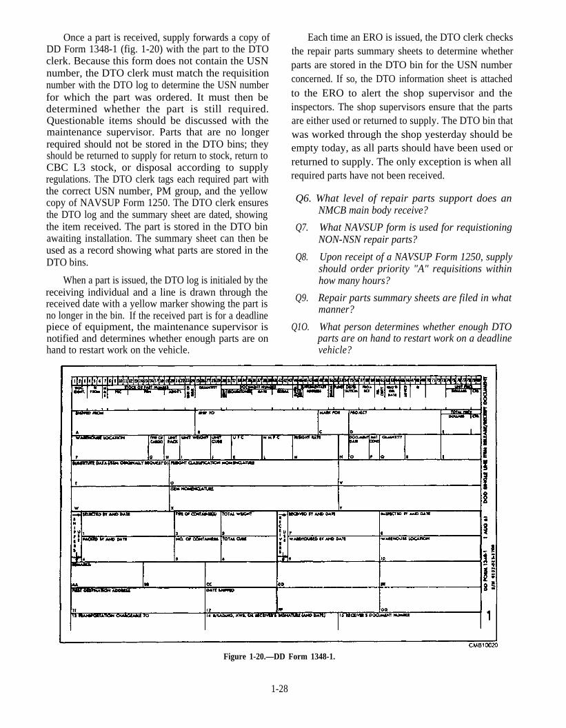
Once a part is received, supply forwards a copy ofDD Form 1348-1 (fig. 1-20) with the part to the DTOclerk. Because this form does not contain the USNnumber, the DTO clerk must match the requisitionnumber with the DTO log to determine the USN numberfor which the part was ordered. It must then bedetermined whether the part is still required.Questionable items should be discussed with themaintenance supervisor. Parts that are no longerrequired should not be stored in the DTO bins; theyshould be returned to supply for return to stock, return toCBC L3 stock, or disposal according to supplyregulations. The DTO clerk tags each required part withthe correct USN number, PM group, and the yellowcopy of NAVSUP Form 1250. The DTO clerk ensuresthe DTO log and the summary sheet are dated, showingthe item received. The part is stored in the DTO binawaiting installation. The summary sheet can then beused as a record showing what parts are stored in theDTO bins.
When a part is issued, the DTO log is initialed by thereceiving individual and a line is drawn through thereceived date with a yellow marker showing the part isno longer in the bin. If the received part is for a deadlinepiece of equipment, the maintenance supervisor isnotified and determines whether enough parts are on
Each time an ERO is issued, the DTO clerk checksthe repair parts summary sheets to determine whetherparts are stored in the DTO bin for the USN numberconcerned. If so, the DTO information sheet is attachedto the ERO to alert the shop supervisor and theinspectors. The shop supervisors ensure that the partsare either used or returned to supply. The DTO bin thatwas worked through the shop yesterday should beempty today, as all parts should have been used orreturned to supply. The only exception is when allrequired parts have not been received.
Q6. What level of repair parts support does anNMCB main body receive?
Q7. What NAVSUP form is used for requistioningNON-NSN repair parts?
Q8. Upon receipt of a NAVSUP Form 1250, supplyshould order priority "A" requisitions withinhow many hours?
Q9. Repair parts summary sheets are filed in whatmanner?
Q1O. What person determines whether enough DTOparts are on hand to restart work on a deadline
hand to restart work on the vehicle. vehicle?
Figure 1-20.—DD Form 1348-1.
1-28
CHAPTER 2
PRINCIPLES OF AN INTERNALCOMBUSTION ENGINE
LEARNING OBJECTIVE: Explain the principles of operation, the differentclassifications, and the measurements and performance standards of an internalcombustion engine.
As a Construction Mechanic, you are concernedwith repairing and replacing worn or broken parts,making various adjustments to vehicles and equipment,and ensuring that they are serviced properly andinspected regularly. To perform these dutiesintelligently, you must fully understand the operationand function of the various components of an internalcombustion engine. This makes your job of diagnosingand correcting troubles much easier. This, in turn, savestime, effort, and money.
This topic discusses the theory and operation of aninternal combustion engine. You also need to becomefamiliar with the terms being used.
INTERNAL COMBUSTION ENGINE
LEARNING OBJECTIVE: Identify the seriesof events, as they occur, in both a gasolineengine and a diesel engine. Describe thedifferences between a four-stroke cycle engineand a two-stroke cycle engine.
Combustion is the act or process of burning. An"external" or "internal" combustion engine is definedsimply as a machine that converts heat energy into
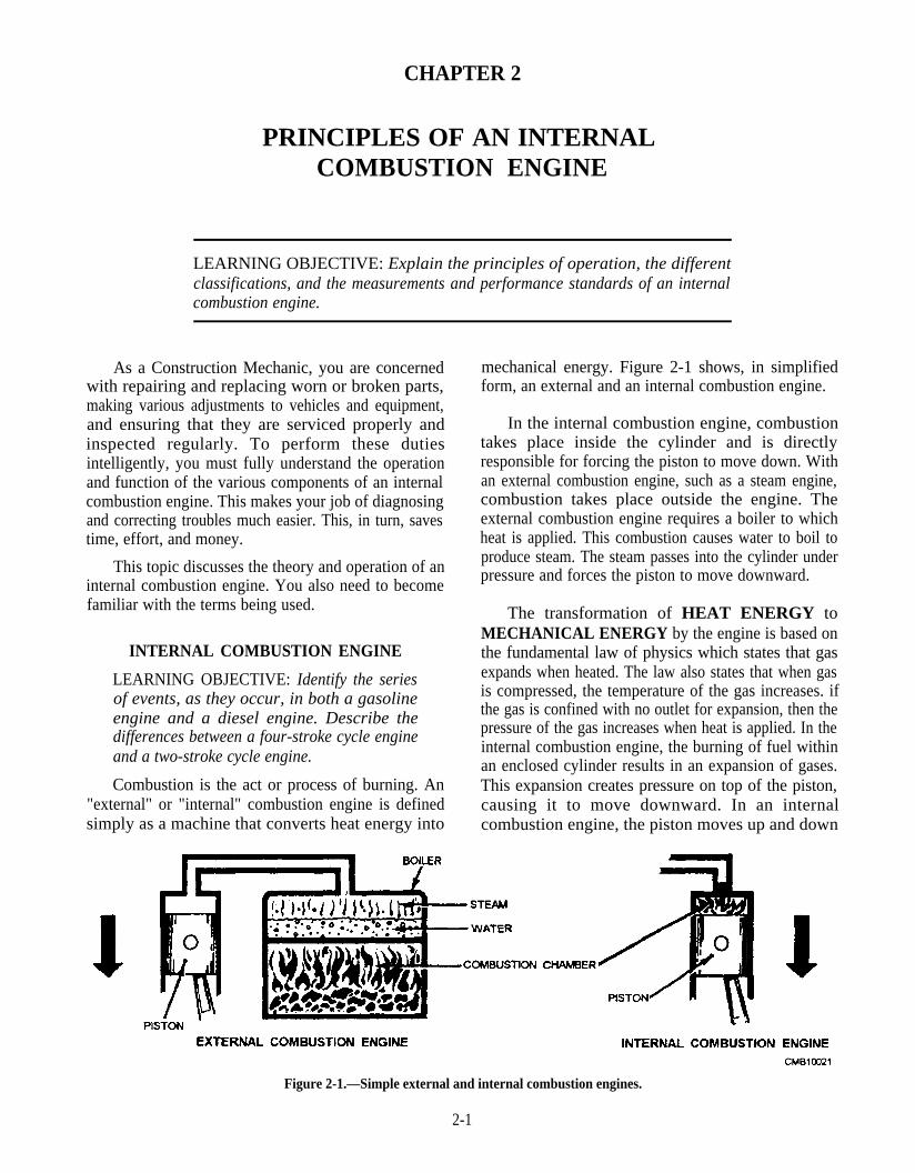
mechanical energy. Figure 2-1 shows, in simplifiedform, an external and an internal combustion engine.
In the internal combustion engine, combustiontakes place inside the cylinder and is directlyresponsible for forcing the piston to move down. Withan external combustion engine, such as a steam engine,combustion takes place outside the engine. Theexternal combustion engine requires a boiler to whichheat is applied. This combustion causes water to boil toproduce steam. The steam passes into the cylinder underpressure and forces the piston to move downward.
The transformation of HEAT ENERGY toMECHANICAL ENERGY by the engine is based onthe fundamental law of physics which states that gasexpands when heated. The law also states that when gasis compressed, the temperature of the gas increases. ifthe gas is confined with no outlet for expansion, then thepressure of the gas increases when heat is applied. In theinternal combustion engine, the burning of fuel withinan enclosed cylinder results in an expansion of gases.This expansion creates pressure on top of the piston,causing it to move downward. In an internalcombustion engine, the piston moves up and down
Figure 2-1.—Simple external and internal combustion engines.
2-1
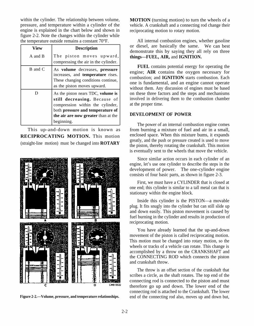
within the cylinder. The relationship between volume,pressure, and temperature within a cylinder of theengine is explained in the chart below and shown infigure 2-2. Note the changes within the cylinder whilethe temperature outside remains a constant 70°F.
View Description
A and B T h e p i s t o n m o v e s u p w a r d ,compressing the air in the cylinder.
B and C As volume decreases, pressureincreases, and temperature rises.These changing conditions continue,as the piston moves upward.
D As the piston nears TDC, volume issti l l decreasing. Because ofcompression within the cylinder,both pressure and temperature ofthe air are now greater than at thebeginning.
This up-and-down motion is known asRECIPROCATING MOTION. This motion
(straight-line motion) must be changed into ROTARY
Figure 2-2.—Volume, pressure, and temperature relationships.
2-2
MOTION (turning motion) to turn the wheels of avehicle. A crankshaft and a connecting rod change theirreciprocating motion to rotary motion.
All internal combustion engines, whether gasolineor diesel, are basically the same. We can bestdemonstrate this by saying they all rely on threethings—FUEL, AIR, and IGNITION.
FUEL contains potential energy for operating theengine; AIR contains the oxygen necessary forcombustion; and IGNITION starts combustion. Eachone is fundamental, and an engine cannot operatewithout them. Any discussion of engines must be basedon these three factors and the steps and mechanismsinvolved in delivering them to the combustion chamberat the proper time.
DEVELOPMENT OF POWER
The power of an internal combustion engine comesfrom burning a mixture of fuel and air in a small,enclosed space. When this mixture bums, it expandsgreatly, and the push or pressure created is used to movethe piston, thereby rotating the crankshaft. This motionis eventually sent to the wheels that move the vehicle.
Since similar action occurs in each cylinder of anengine, let’s use one cylinder to describe the steps in thedevelopment of power. The one-cylinder engineconsists of four basic parts, as shown in figure 2-3.
First, we must have a CYLINDER that is closed atone end; this cylinder is similar to a tall metal can that isstationary within the engine block.
Inside this cylinder is the PISTON—a movableplug. It fits snugly into the cylinder but can still slide upand down easily. This piston movement is caused byfuel burning in the cylinder and results in production ofreciprocating motion.
You have already learned that the up-and-downmovement of the piston is called reciprocating motion.This motion must be changed into rotary motion, so thewheels or tracks of a vehicle can rotate. This change isaccomplished by a throw on the CRANKSHAFT andthe CONNECTING ROD which connects the pistonand crankshaft throw.
The throw is an offset section of the crankshaft thatscribes a circle, as the shaft rotates. The top end of theconnecting rod is connected to the piston and musttherefore go up and down. The lower end of theconnecting rod is attached to the Crankshaft. The lowerend of the connecting rod also, moves up and down but,

Figure 2-3.—Cylinder, piston, connecting rod, and crankshaft for a one-cylinder engine.
because it is attached to the crankshaft, it must alsomove in a circle.
When the piston of the engine slides downwardbecause of the pressure of the expanding gases in thecylinder, the upper end of the connecting rod movesdownward with the piston in a straight line. The lowerend of the connecting rod moves down and in a circularmotion at the same time. This moves the throw and, inturn, the throw rotates the crankshaft; this rotation is thedesired result. So remember, the crankshaft and
connecting rod combination is a mechanism for thepurpose of changing straight line, or reciprocatingmotion to circular, or rotary motion.
FOUR-STROKE-CYCLE ENGINE
Each movement of the piston from top to bottom orfrom bottom to top is called a stroke. The piston takestwo strokes (an up stroke and a down stroke), as thecrankshaft makes one complete revolution Figure 2-4
Figure 2-4.—Piston stroke technology.
2-3
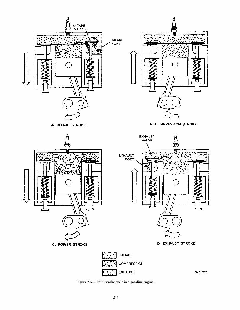
Figure 2-5.—Four-stroke cycle in a gasoline engine.
2-4
shows the motion of a piston in its cylinder. The pistonis connected to the rotating crankshaft by a connectingrod. In view A of figure 2-4, the piston is at thebeginning or top of the stroke. As the crankshaftrotates, the connecting rod pulls the piston down. Whenthe crankshaft has rotated one-half turn, the piston is atthe bottom of the stroke. Now look at view B of figure2-4. As the crankshaft continues to rotate, theconnecting rod begins to push the piston up. Theposition of the piston at the instant its motion changesfrom down to up is known as bottom dead center(BDC). The piston continues moving upward until themotion of the crankshaft causes it to begin movingdown. This position of the piston at the instant itsmotion changes from up to down is known as top deadcenter (TDC). The term dead indicates where onemotion has stopped (the piston has reached the end ofthe stroke) and its opposite turning motion is ready tostart. These positions are called rock positions anddiscussed later under "Timing."
The following paragraphs provide a simplifiedexplanation of the action within the cylinder of a four-stroke-cycle gasoline engine. It is referred to as a four-stroke cycle because it requires four complete strokes ofthe piston to complete one engine cycle. Later a two-stroke-cycle engine is discussed. The action of a four-stroke-cycle engine may be divided into four parts: theintake stroke, the compression stroke, the power stroke,and the exhaust stroke.
Intake Stroke
The first stroke in the sequence is called theINTAKE stroke (figs. 2-5 and 2-6). During this stroke,the piston is moving downward and the intake valve isopen. This downward movement of the piston producesa partial vacuum in the cylinder, and the air-fuel mixturerushes into the cylinder past the open intake valve. Thisis somewhat the same effect as when you drink througha straw. A partial vacuum is produced in the mouth andthe liquid moves up through the straw to fill the vacuum.
Compression Stroke
When the piston reaches bottom dead center (BDC)at the end of the intake stroke and is therefore at thebottom of the cylinder, the intake valve closes. Thisseals the upper end of the cylinder. As the crankshaftcontinues to rotate, it pushes up through the connectingrod on the piston. The piston is therefore pushedupward and compresses the combustible mixture in thecylinder; this is called the COMPRESSION stroke
(figs. 2-5 and 2-6). In gasoline engines, the mixture iscompressed to about one eighth of its original volume;this is called 8 to 1 compression ratio. This compressionof the air-fuel mixture increases the pressure within thecylinder. Compressing the mixture makes it even morecombustible; not only does the pressure in the cylinderincrease, but the temperature of the mixture alsoincreases.
Power Stroke
As the piston reaches top dead center (TDC) at theend of the compression stroke and therefore has movedto the top of the cylinder, the compressed air-fuelmixture is ignited. The ignition system causes anelectric spark to occur suddenly in the cylinder, and thespark ignites the air-fuel mixture. In burning, themixture gets very hot and tries to expand in alldirections. The pressure rises between 600 to 700pounds per square inch. Since the piston is the onlything that can move, the force produced by theexpanded gases forces the piston down. This force, orthrust, is carried through the connecting rod to thecrankshaft throw on the crankshaft. The crankshaft isgiven a powerful push This is called the POWERstroke (figs. 2-5 and 2-6). This turning effort, rapidlyrepeated in the engine and carried through gears andshafts, turns the wheels of a vehicle and causes it tomove.
Exhaust Stroke
After the air-fuel mixture has burned, it must becleared from the cylinder. This is done by opening theexhaust valve just as the power stroke is finished, andthe piston starts back up on the EXHAUST stroke (figs.2-5 and 2-6). The piston forces the burned gases out ofthe cylinder past the open exhaust valve.
TWO-STROKE-CYCLE ENGINE
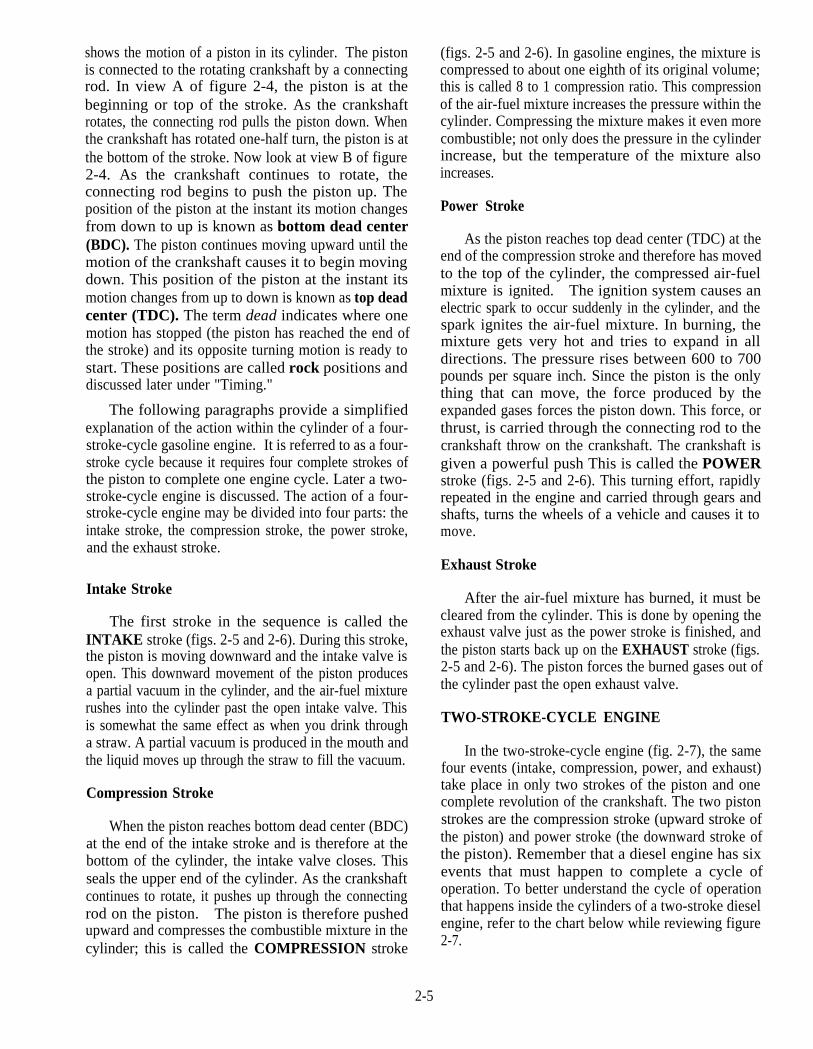
In the two-stroke-cycle engine (fig. 2-7), the samefour events (intake, compression, power, and exhaust)take place in only two strokes of the piston and onecomplete revolution of the crankshaft. The two pistonstrokes are the compression stroke (upward stroke ofthe piston) and power stroke (the downward stroke ofthe piston). Remember that a diesel engine has sixevents that must happen to complete a cycle ofoperation. To better understand the cycle of operationthat happens inside the cylinders of a two-stroke dieselengine, refer to the chart below while reviewing figure2-7.
2-5
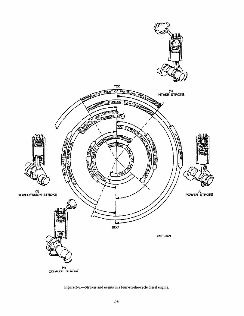
Figure 2-6.—Strokes and events in a four-stroke-cycle diesel engine.
2-6
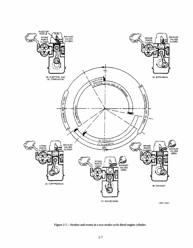
Figure 2-7.—Strokes and events in a two-stroke-cycle diesel engine cylinder.
2-7
Sequence of events
(1) Scavenging (intake)
(2) Compression
(3) Injection/ignition
and
(4) Combustion
(5) Expansion (power)
(6) Exhaust
Description of Events
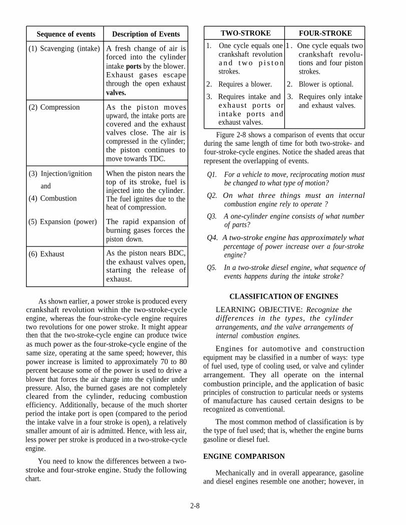
A fresh change of air isforced into the cylinderintake ports by the blower.Exhaust gases escapethrough the open exhaustvalves.
As the piston movesupward, the intake ports arecovered and the exhaustvalves close. The air iscompressed in the cylinder;the piston continues tomove towards TDC.
When the piston nears thetop of its stroke, fuel isinjected into the cylinder.The fuel ignites due to theheat of compression.
The rapid expansion ofburning gases forces thepiston down.
As the piston nears BDC,the exhaust valves open,starting the release ofexhaust.
As shown earlier, a power stroke is produced everycrankshaft revolution within the two-stroke-cycleengine, whereas the four-stroke-cycle engine requirestwo revolutions for one power stroke. It might appearthen that the two-stroke-cycle engine can produce twiceas much power as the four-stroke-cycle engine of thesame size, operating at the same speed; however, thispower increase is limited to approximately 70 to 80percent because some of the power is used to drive ablower that forces the air charge into the cylinder underpressure. Also, the burned gases are not completelycleared from the cylinder, reducing combustionefficiency. Additionally, because of the much shorterperiod the intake port is open (compared to the periodthe intake valve in a four stroke is open), a relativelysmaller amount of air is admitted. Hence, with less air,less power per stroke is produced in a two-stroke-cycleengine.
You need to know the differences between a two-stroke and four-stroke engine. Study the followingchart.
TWO-STROKE FOUR-STROKE
1. One cycle equals one 1 . One cycle equals twocrankshaft revolution crankshaft revolu-a n d t w o p i s t o n tions and four pistonstrokes. strokes.
2. Requires a blower. 2. Blower is optional.
3. Requires intake and 3. Requires only intakeexhaust ports or and exhaust valves.intake ports andexhaust valves.
Figure 2-8 shows a comparison of events that occurduring the same length of time for both two-stroke- andfour-stroke-cycle engines. Notice the shaded areas thatrepresent the overlapping of events.
Q1. For a vehicle to move, reciprocating motion mustbe changed to what type of motion?
Q2. On what three things must an internalcombustion engine rely to operate ?
Q3. A one-cylinder engine consists of what numberof parts?
Q4. A two-stroke engine has approximately whatpercentage of power increase over a four-strokeengine?
Q5. In a two-stroke diesel engine, what sequence ofevents happens during the intake stroke?
CLASSIFICATION OF ENGINES
LEARNING OBJECTIVE: Recognize thedifferences in the types, the cylinderarrangements, and the valve arrangements ofinternal combustion engines.
Engines for automotive and constructionequipment may be classified in a number of ways: typeof fuel used, type of cooling used, or valve and cylinderarrangement. They all operate on the internalcombustion principle, and the application of basicprinciples of construction to particular needs or systemsof manufacture has caused certain designs to berecognized as conventional.
The most common method of classification is bythe type of fuel used; that is, whether the engine burnsgasoline or diesel fuel.
ENGINE COMPARISON
Mechanically and in overall appearance, gasolineand diesel engines resemble one another; however, in
2-8
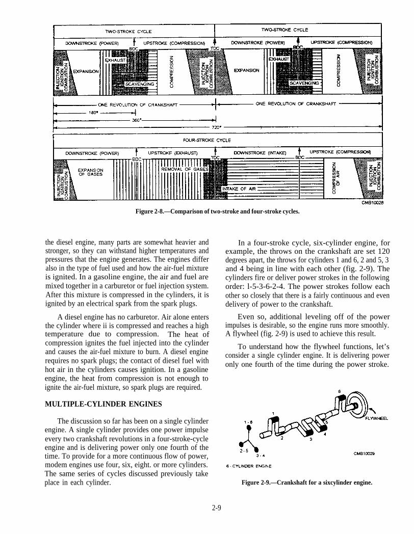
Figure 2-8.—Comparison of two-stroke and four-stroke cycles.
the diesel engine, many parts are somewhat heavier andstronger, so they can withstand higher temperatures andpressures that the engine generates. The engines differalso in the type of fuel used and how the air-fuel mixtureis ignited. In a gasoline engine, the air and fuel aremixed together in a carburetor or fuel injection system.After this mixture is compressed in the cylinders, it isignited by an electrical spark from the spark plugs.
A diesel engine has no carburetor. Air alone entersthe cylinder where ii is compressed and reaches a hightemperature due to compression. The heat ofcompression ignites the fuel injected into the cylinderand causes the air-fuel mixture to burn. A diesel enginerequires no spark plugs; the contact of diesel fuel withhot air in the cylinders causes ignition. In a gasolineengine, the heat from compression is not enough toignite the air-fuel mixture, so spark plugs are required.
MULTIPLE-CYLINDER ENGINES
The discussion so far has been on a single cylinderengine. A single cylinder provides one power impulseevery two crankshaft revolutions in a four-stroke-cycleengine and is delivering power only one fourth of thetime. To provide for a more continuous flow of power,modem engines use four, six, eight. or more cylinders.The same series of cycles discussed previously takeplace in each cylinder.
In a four-stroke cycle, six-cylinder engine, forexample, the throws on the crankshaft are set 120degrees apart, the throws for cylinders 1 and 6, 2 and 5, 3and 4 being in line with each other (fig. 2-9). Thecylinders fire or deliver power strokes in the followingorder: l-5-3-6-2-4. The power strokes follow eachother so closely that there is a fairly continuous and evendelivery of power to the crankshaft.
Even so, additional leveling off of the powerimpulses is desirable, so the engine runs more smoothly.A flywheel (fig. 2-9) is used to achieve this result.
To understand how the flywheel functions, let’sconsider a single cylinder engine. It is delivering poweronly one fourth of the time during the power stroke.
Figure 2-9.—Crankshaft for a sixcylinder engine.
2-9
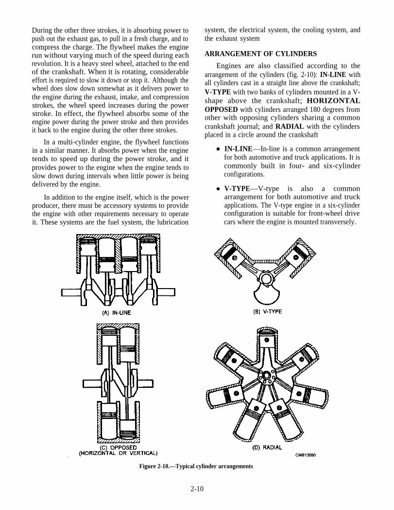
During the other three strokes, it is absorbing power topush out the exhaust gas, to pull in a fresh charge, and tocompress the charge. The flywheel makes the enginerun without varying much of the speed during eachrevolution. It is a heavy steel wheel, attached to the endof the crankshaft. When it is rotating, considerableeffort is required to slow it down or stop it. Although thewheel does slow down somewhat as it delivers power tothe engine during the exhaust, intake, and compressionstrokes, the wheel speed increases during the powerstroke. In effect, the flywheel absorbs some of theengine power during the power stroke and then providesit back to the engine during the other three strokes.
In a multi-cylinder engine, the flywheel functionsin a similar manner. It absorbs power when the enginetends to speed up during the power stroke, and itprovides power to the engine when the engine tends toslow down during intervals when little power is beingdelivered by the engine.
In addition to the engine itself, which is the powerproducer, there must be accessory systems to providethe engine with other requirements necessary to operateit. These systems are the fuel system, the lubrication
system, the electrical system, the cooling system, andthe exhaust system
ARRANGEMENT OF CYLINDERS
Engines are also classified according to thearrangement of the cylinders (fig. 2-10): IN-LINE withall cylinders cast in a straight line above the crankshaft;V-TYPE with two banks of cylinders mounted in a V-shape above the crankshaft; HORIZONTALOPPOSED with cylinders arranged 180 degrees fromother with opposing cylinders sharing a commoncrankshaft journal; and RADIAL with the cylindersplaced in a circle around the crankshaft
IN-LINE—In-line is a common arrangementfor both automotive and truck applications. It iscommonly built in four- and six-cylinderconfigurations.
V-TYPE—V-type is also a commonarrangement for both automotive and truckapplications. The V-type engine in a six-cylinderconfiguration is suitable for front-wheel drivecars where the engine is mounted transversely.
Figure 2-10.—Typical cylinder arrangements
2-10
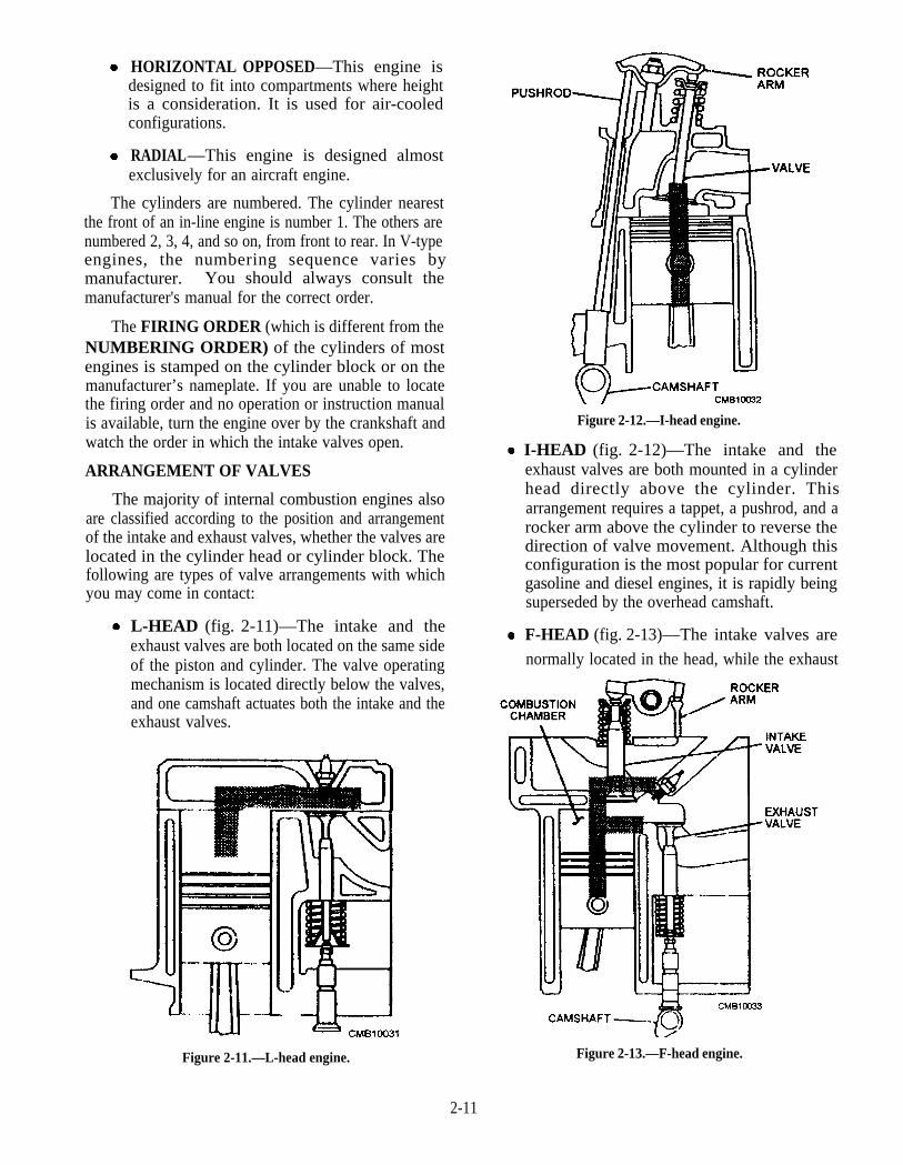
HORIZONTAL OPPOSED—This engine isdesigned to fit into compartments where heightis a consideration. It is used for air-cooledconfigurations.
RADIAL—This engine is designed almostexclusively for an aircraft engine.
The cylinders are numbered. The cylinder nearestthe front of an in-line engine is number 1. The others arenumbered 2, 3, 4, and so on, from front to rear. In V-typeengines, the numbering sequence varies bymanufacturer. You should always consult themanufacturer's manual for the correct order.
The FIRING ORDER (which is different from theNUMBERING ORDER) of the cylinders of mostengines is stamped on the cylinder block or on themanufacturer’s nameplate. If you are unable to locatethe firing order and no operation or instruction manualis available, turn the engine over by the crankshaft andwatch the order in which the intake valves open.
ARRANGEMENT OF VALVES
The majority of internal combustion engines alsoare classified according to the position and arrangementof the intake and exhaust valves, whether the valves arelocated in the cylinder head or cylinder block. Thefollowing are types of valve arrangements with whichyou may come in contact:
L-HEAD (fig. 2-11)—The intake and theexhaust valves are both located on the same sideof the piston and cylinder. The valve operatingmechanism is located directly below the valves,and one camshaft actuates both the intake and theexhaust valves.
Figure 2-11.—L-head engine.
Figure 2-12.—I-head engine.
I-HEAD (fig. 2-12)—The intake and theexhaust valves are both mounted in a cylinderhead directly above the cylinder. Thisarrangement requires a tappet, a pushrod, and arocker arm above the cylinder to reverse thedirection of valve movement. Although thisconfiguration is the most popular for currentgasoline and diesel engines, it is rapidly beingsuperseded by the overhead camshaft.
F-HEAD (fig. 2-13)—The intake valves are
normally located in the head, while the exhaust
Figure 2-13.—F-head engine.
2-11
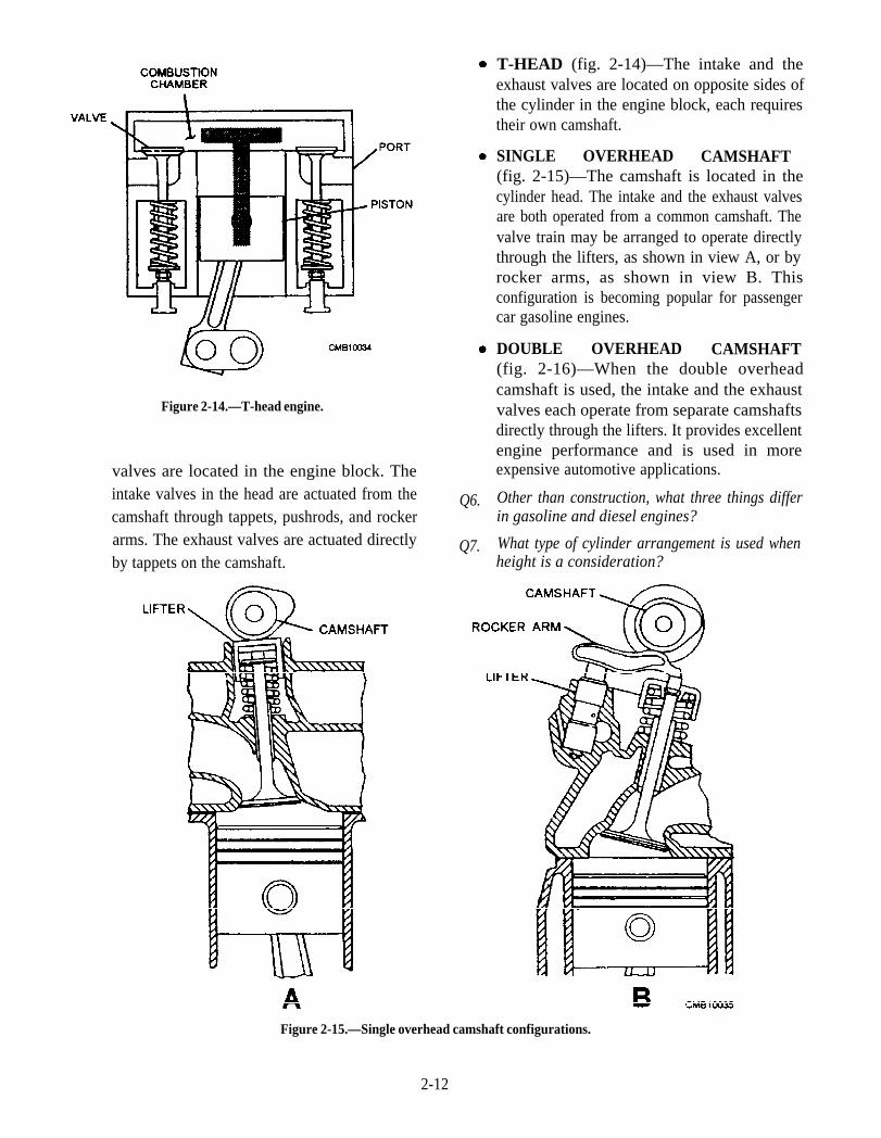
Figure 2-14.—T-head engine.
valves are located in the engine block. Theintake valves in the head are actuated from thecamshaft through tappets, pushrods, and rockerarms. The exhaust valves are actuated directlyby tappets on the camshaft.
Q6.
Q7.
T-HEAD (fig. 2-14)—The intake and theexhaust valves are located on opposite sides ofthe cylinder in the engine block, each requirestheir own camshaft.
SINGLE OVERHEAD CAMSHAFT(fig. 2-15)—The camshaft is located in thecylinder head. The intake and the exhaust valvesare both operated from a common camshaft. Thevalve train may be arranged to operate directlythrough the lifters, as shown in view A, or byrocker arms, as shown in view B. Thisconfiguration is becoming popular for passengercar gasoline engines.
DOUBLE OVERHEAD CAMSHAFT(fig. 2-16)—When the double overheadcamshaft is used, the intake and the exhaustvalves each operate from separate camshaftsdirectly through the lifters. It provides excellentengine performance and is used in moreexpensive automotive applications.
Other than construction, what three things differin gasoline and diesel engines?
What type of cylinder arrangement is used whenheight is a consideration?
Figure 2-15.—Single overhead camshaft configurations.
2-12
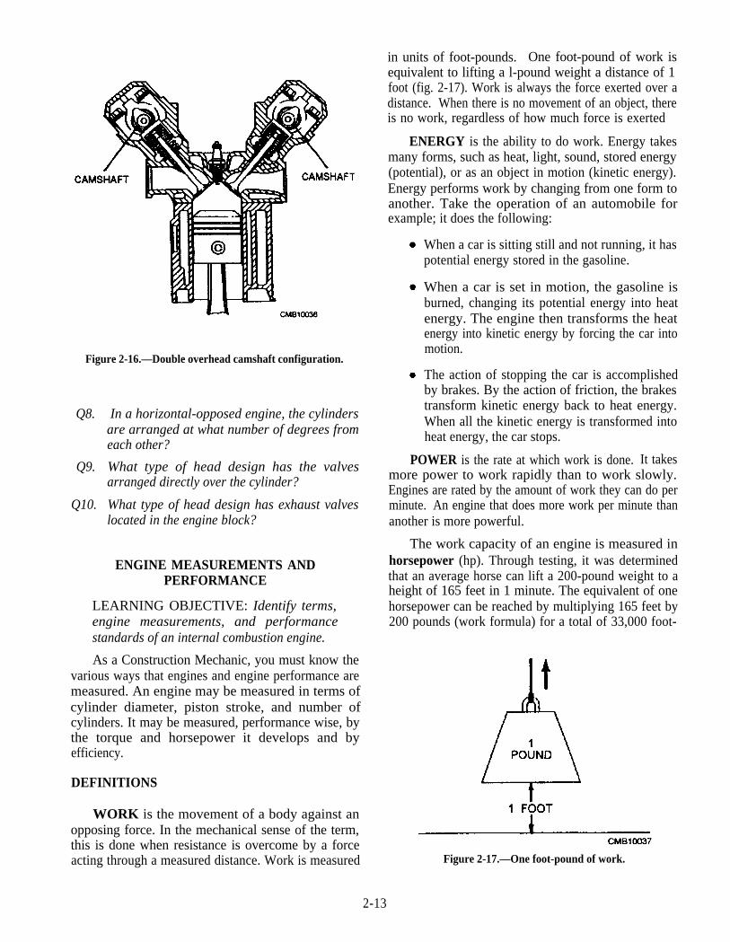
Figure 2-16.—Double overhead camshaft configuration.
Q8. In a horizontal-opposed engine, the cylindersare arranged at what number of degrees fromeach other?
Q9. What type of head design has the valvesarranged directly over the cylinder?
Q10. What type of head design has exhaust valveslocated in the engine block?
ENGINE MEASUREMENTS ANDPERFORMANCE
LEARNING OBJECTIVE: Identify terms,engine measurements, and performancestandards of an internal combustion engine.
As a Construction Mechanic, you must know thevarious ways that engines and engine performance aremeasured. An engine may be measured in terms ofcylinder diameter, piston stroke, and number ofcylinders. It may be measured, performance wise, bythe torque and horsepower it develops and byefficiency.
DEFINITIONS
WORK is the movement of a body against anopposing force. In the mechanical sense of the term,this is done when resistance is overcome by a forceacting through a measured distance. Work is measured
in units of foot-pounds. One foot-pound of work isequivalent to lifting a l-pound weight a distance of 1foot (fig. 2-17). Work is always the force exerted over adistance. When there is no movement of an object, thereis no work, regardless of how much force is exerted
ENERGY is the ability to do work. Energy takesmany forms, such as heat, light, sound, stored energy(potential), or as an object in motion (kinetic energy).Energy performs work by changing from one form toanother. Take the operation of an automobile forexample; it does the following:
When a car is sitting still and not running, it haspotential energy stored in the gasoline.
When a car is set in motion, the gasoline isburned, changing its potential energy into heatenergy. The engine then transforms the heatenergy into kinetic energy by forcing the car intomotion.
The action of stopping the car is accomplishedby brakes. By the action of friction, the brakestransform kinetic energy back to heat energy.When all the kinetic energy is transformed intoheat energy, the car stops.
POWER is the rate at which work is done. It takesmore power to work rapidly than to work slowly.Engines are rated by the amount of work they can do perminute. An engine that does more work per minute thananother is more powerful.
The work capacity of an engine is measured inhorsepower (hp). Through testing, it was determinedthat an average horse can lift a 200-pound weight to aheight of 165 feet in 1 minute. The equivalent of onehorsepower can be reached by multiplying 165 feet by200 pounds (work formula) for a total of 33,000 foot-
Figure 2-17.—One foot-pound of work.
2-13
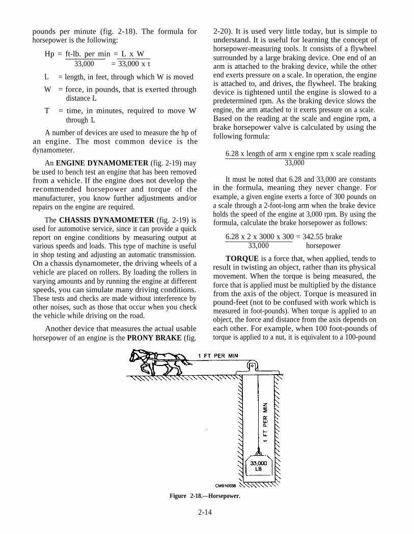
pounds per minute (fig. 2-18). The formula forhorsepower is the following:
Hp = ft-lb. per min = L x W33,000 = 33,000 x t
L = length, in feet, through which W is moved
W = force, in pounds, that is exerted throughdistance L
T = time, in minutes, required to move Wthrough L
A number of devices are used to measure the hp ofan engine. The most common device is thedynamometer.
An ENGINE DYNAMOMETER (fig. 2-19) maybe used to bench test an engine that has been removedfrom a vehicle. If the engine does not develop therecommended horsepower and torque of themanufacturer, you know further adjustments and/orrepairs on the engine are required.
The CHASSIS DYNAMOMETER (fig. 2-19) isused for automotive service, since it can provide a quickreport on engine conditions by measuring output atvarious speeds and loads. This type of machine is usefulin shop testing and adjusting an automatic transmission.On a chassis dynamometer, the driving wheels of avehicle are placed on rollers. By loading the rollers invarying amounts and by running the engine at differentspeeds, you can simulate many driving conditions.These tests and checks are made without interference byother noises, such as those that occur when you checkthe vehicle while driving on the road.
Another device that measures the actual usablehorsepower of an engine is the PRONY BRAKE (fig.
2-20). It is used very little today, but is simple tounderstand. It is useful for learning the concept ofhorsepower-measuring tools. It consists of a flywheelsurrounded by a large braking device. One end of anarm is attached to the braking device, while the otherend exerts pressure on a scale. In operation, the engineis attached to, and drives, the flywheel. The brakingdevice is tightened until the engine is slowed to apredetermined rpm. As the braking device slows theengine, the arm attached to it exerts pressure on a scale.Based on the reading at the scale and engine rpm, abrake horsepower valve is calculated by using thefollowing formula:
6.28 x length of arm x engine rpm x scale reading33,000
It must be noted that 6.28 and 33,000 are constantsin the formula, meaning they never change. Forexample, a given engine exerts a force of 300 pounds ona scale through a 2-foot-long arm when the brake deviceholds the speed of the engine at 3,000 rpm. By using theformula, calculate the brake horsepower as follows:
6.28 x 2 x 3000 x 300 = 342.55 brake33,000 horsepower
TORQUE is a force that, when applied, tends toresult in twisting an object, rather than its physicalmovement. When the torque is being measured, theforce that is applied must be multiplied by the distancefrom the axis of the object. Torque is measured inpound-feet (not to be confused with work which ismeasured in foot-pounds). When torque is applied to anobject, the force and distance from the axis depends oneach other. For example, when 100 foot-pounds oftorque is applied to a nut, it is equivalent to a 100-pound
Figure 2-18.—Horsepower.
2-14
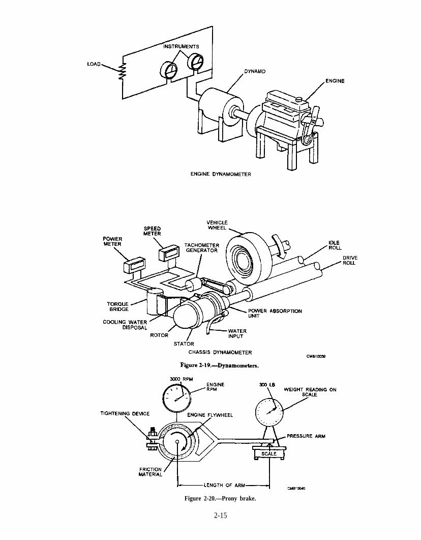
Figure 2-20.—Prony brake.
2-15

force being applied from a wrench that is l-foot long.When a 2-foot-long wrench is used, only a 50-poundforce is required. An illustration of a torque wrench inuse is shown in figure 2-21.
DO NOT confuse torque with work or with power.Both work and power indicate motion, but torque doesnot. It is merely a turning effort the engine applies to thewheels through gears and shafts.
ENGINE TORQUE is a rating of the turning forceat the engine crankshaft. When combustion pressurepushes the piston down, a strong rotating force isapplied to the crankshaft. This turning force is sent tothe transmission or transaxle, drive line or drive lines,and drive wheels, moving the vehicle. Engine torquespecifications are provided in a shop manual for aparticular vehicle. One example, 78 pound-feet @3,000 (at 3,000) rpm is given for one particular engine.This engine is capable of producing 78 pound-feet oftorque when operating at 3,000 revolutions per minute.
FRICTION is the resistance to motion betweentwo objects in contact with each other. The reason a sleddoes not slide on bare earth is because of friction Itslides on snow because snow offers little resistance,while the bare earth offers a great deal of resistance.
Friction is both desirable and undesirable in anautomobile or any other vehicle. Friction in an engine isundesirable because it decreases the power output; inother words, it dissipates some of the energy the engine
2-16
Figure 2-21.—Torque wrench in use, tightening main bearing studof an engine.
produces. This is overcome by using oil, so movingcomponents in the engine slide or roll over each othersmoothly. Frictional horsepower (fhp) is the powerneeded to overcome engine friction. It is a measure ofresistance to movement between engine parts.Frictional horsepower is POWER LOST to friction. Itreduces the amount of power left to propel a vehicle.Friction, however, is desirable in clutches and brakes,since friction is exactly what is needed for them toperform their function properly.
One other term you often encounter is INERTIA.Inertia is a characteristic of all material objects. Itcauses them to resist change in speed or direction oftravel. A motionless object tends to remain at rest, and amoving object tends to keep moving at the same speedand in the same direction. A good example of inertia isthe tendency of your automobile to keep moving evenafter you have removed your foot from the accelerator.You apply the brake to overcome the inertia of theautomobile or its tendency to keep moving.
The term efficiency means the relationship betweenthe actual and theoretical power output. Volumetricefficiency (fig. 2-22) is the ratio between the amount ofair-fuel mixture that actually enters the cylinder and theamount that could enter under ideal conditions. Thegreater volumetric efficiency, the greater the amount ofair-fuel mixture entering the cylinder; and the greater
Fire 2-22.—Demonstrating volumetric efficiency.
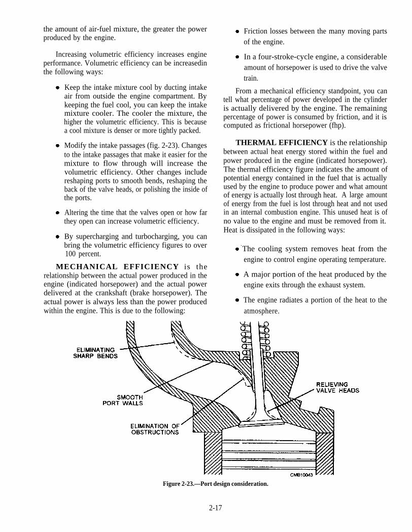
the amount of air-fuel mixture, the greater the powerproduced by the engine.
Increasing volumetric efficiency increases engineperformance. Volumetric efficiency can be increasedinthe following ways:
Keep the intake mixture cool by ducting intakeair from outside the engine compartment. Bykeeping the fuel cool, you can keep the intakemixture cooler. The cooler the mixture, thehigher the volumetric efficiency. This is becausea cool mixture is denser or more tightly packed.
Modify the intake passages (fig. 2-23). Changesto the intake passages that make it easier for themixture to flow through will increase thevolumetric efficiency. Other changes includereshaping ports to smooth bends, reshaping theback of the valve heads, or polishing the inside ofthe ports.
Altering the time that the valves open or how farthey open can increase volumetric efficiency.
By supercharging and turbocharging, you canbring the volumetric efficiency figures to over100 percent.
MECHANICAL EFFICIENCY is therelationship between the actual power produced in theengine (indicated horsepower) and the actual powerdelivered at the crankshaft (brake horsepower). Theactual power is always less than the power producedwithin the engine. This is due to the following:
Friction losses between the many moving partsof the engine.
In a four-stroke-cycle engine, a considerableamount of horsepower is used to drive the valvetrain.
From a mechanical efficiency standpoint, you cantell what percentage of power developed in the cylinderis actually delivered by the engine. The remainingpercentage of power is consumed by friction, and it iscomputed as frictional horsepower (fhp).
THERMAL EFFICIENCY is the relationshipbetween actual heat energy stored within the fuel andpower produced in the engine (indicated horsepower).The thermal efficiency figure indicates the amount ofpotential energy contained in the fuel that is actuallyused by the engine to produce power and what amountof energy is actually lost through heat. A large amountof energy from the fuel is lost through heat and not usedin an internal combustion engine. This unused heat is ofno value to the engine and must be removed from it.Heat is dissipated in the following ways:
The cooling system removes heat from theengine to control engine operating temperature.
A major portion of the heat produced by theengine exits through the exhaust system.
The engine radiates a portion of the heat to theatmosphere.
Figure 2-23.—Port design consideration.
2-17
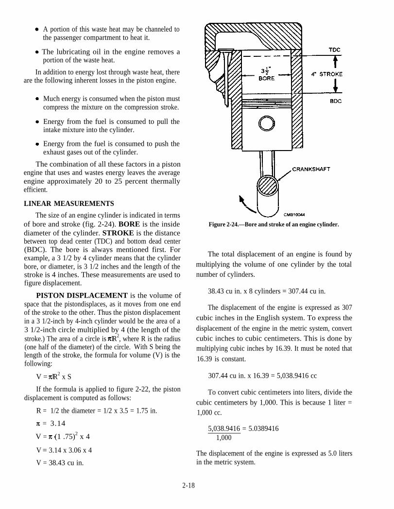
A portion of this waste heat may be channeled tothe passenger compartment to heat it.
The lubricating oil in the engine removes aportion of the waste heat.
In addition to energy lost through waste heat, thereare the following inherent losses in the piston engine.
Much energy is consumed when the piston mustcompress the mixture on the compression stroke.
Energy from the fuel is consumed to pull theintake mixture into the cylinder.
Energy from the fuel is consumed to push theexhaust gases out of the cylinder.
The combination of all these factors in a pistonengine that uses and wastes energy leaves the averageengine approximately 20 to 25 percent thermallyefficient.
LINEAR MEASUREMENTS
The size of an engine cylinder is indicated in termsof bore and stroke (fig. 2-24). BORE is the insidediameter of the cylinder. STROKE is the distancebetween top dead center (TDC) and bottom dead center(BDC). The bore is always mentioned first. Forexample, a 3 1/2 by 4 cylinder means that the cylinderbore, or diameter, is 3 1/2 inches and the length of thestroke is 4 inches. These measurements are used tofigure displacement.
PISTON DISPLACEMENT is the volume ofspace that the pistondisplaces, as it moves from one endof the stroke to the other. Thus the piston displacementin a 3 1/2-inch by 4-inch cylinder would be the area of a3 1/2-inch circle multiplied by 4 (the length of thestroke.) The area of a circle is R2, where R is the radius(one half of the diameter) of the circle. With S being thelength of the stroke, the formula for volume (V) is thefollowing:
V = R2 x S
= 3.14
V = (1 .75)2 x 4
V = 3.14 x 3.06 x 4
V = 38.43 cu in.
If the formula is applied to figure 2-22, the pistondisplacement is computed as follows:
R = 1/2 the diameter = 1/2 x 3.5 = 1.75 in.
Figure 2-24.—Bore and stroke of an engine cylinder.
The total displacement of an engine is found bymultiplying the volume of one cylinder by the totalnumber of cylinders.
38.43 cu in. x 8 cylinders = 307.44 cu in.
The displacement of the engine is expressed as 307cubic inches in the English system. To express thedisplacement of the engine in the metric system, convertcubic inches to cubic centimeters. This is done bymultiplying cubic inches by 16.39. It must be noted that16.39 is constant.
307.44 cu in. x 16.39 = 5,038.9416 cc
To convert cubic centimeters into liters, divide thecubic centimeters by 1,000. This is because 1 liter =1,000 cc.
5,038.9416 = 5.03894161,000
The displacement of the engine is expressed as 5.0 litersin the metric system.
2-18
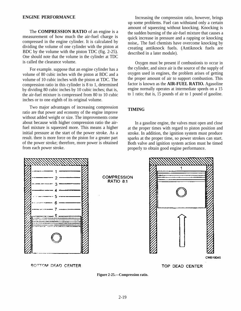
ENGINE PERFORMANCE
The COMPRESSION RATIO of an engine is ameasurement of how much the air-fuel charge iscompressed in the engine cylinder. It is calculated bydividing the volume of one cylinder with the piston atBDC by the volume with the piston TDC (fig. 2-25).One should note that the volume in the cylinder at TDCis called the clearance volume.
For example. suppose that an engine cylinder has avolume of 80 cubic inches with the piston at BDC and avolume of 10 cubic inches with the piston at TDC. Thecompression ratio in this cylinder is 8 to 1, determinedby dividing 80 cubic inches by 10 cubic inches; that is,the air-fuel mixture is compressed from 80 to 10 cubicinches or to one eighth of its original volume.
Two major advantages of increasing compressionratio are that power and economy of the engine improvewithout added weight or size. The improvements comeabout because with higher compression ratio the air-fuel mixture is squeezed more. This means a higherinitial pressure at the start of the power stroke. As aresult. there is more force on the piston for a greater partof the power stroke; therefore, more power is obtainedfrom each power stroke.
Increasing the compression ratio, however, bringsup some problems. Fuel can withstand only a certainamount of squeezing without knocking. Knocking isthe sudden burning of the air-fuel mixture that causes aquick increase in pressure and a rapping or knockingnoise,. The fuel chemists have overcome knocking bycreating antiknock fuels. (Antiknock fuels aredescribed in a later module).
Oxygen must be present if combustionis to occur inthe cylinder, and since air is the source of the supply ofoxygen used in engines, the problem arises of gettingthe proper amount of air to support combustion. Thisfactor is known as the AIR-FUEL RATIO. Agasolineengine normally operates at intermediate speeds on a 15to 1 ratio; that is, 15 pounds of air to 1 pound of gasoline.
TIMING
In a gasoline engine, the valves must open and closeat the proper times with regard to piston position andstroke. In addition, the ignition system must producesparks at the proper time, so power strokes can start.Both valve and ignition system action must he timedproperly to obtain good engine performance.
Figure 2-25.—Compression ratio.
2-19
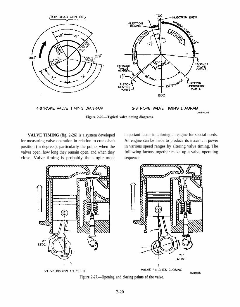
VALVE TIMING (fig. 2-26) is a system developedfor measuring valve operation in relation to crankshaftposition (in degrees), particularly the points when thevalves open, how long they remain open, and when theyclose. Valve timing is probably the single most
important factor in tailoring an engine for special needs.An engine can be made to produce its maximum powerin various speed ranges by altering valve timing. Thefollowing factors together make up a valve operatingsequence:
Figure 2-26.—Typical valve timing diagrams.
Figure 2-27.—Opening and closing points of the valve.
2-20

Figure 2-28.—Valve opening duration.
1. The opening and closing points (fig. 2-27) arepositions of the crankshaft (in degrees) when the valvesjust begin to open and just finish closing.
2. Duration (fig. 2-28) is the amount of crankshaftrotation (in degrees) that a given valve remains open.
3. Valve overlap (fig. 2-29) is a period in a four-stroke cycle when the intake valve opens before theexhaust valve closes.
4. Valve timing considerations, throughout thecrankshaft revolution, the speed of the piston changes.From a stop at the bottom of the stroke, the pistonreaches its maximum speed halfway through the strokeand gradually slows to a stop as it reaches the end of thestroke. The piston behaves exactly the same on thedownstroke. One of these periods begins atapproximately 15 to 20 degrees before top dead center(BTDC) and ends at approximately 15 to 20 degrees
Figure 2-29.—Valve timing diagram showing valve overlap,
2-21
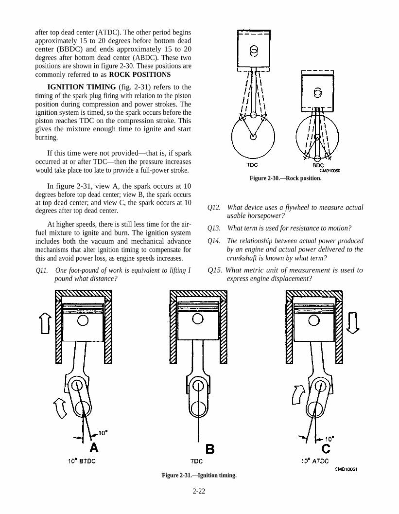
after top dead center (ATDC). The other period beginsapproximately 15 to 20 degrees before bottom deadcenter (BBDC) and ends approximately 15 to 20degrees after bottom dead center (ABDC). These twopositions are shown in figure 2-30. These positions arecommonly referred to as ROCK POSITIONS
IGNITION TIMING (fig. 2-31) refers to thetiming of the spark plug firing with relation to the pistonposition during compression and power strokes. Theignition system is timed, so the spark occurs before thepiston reaches TDC on the compression stroke. Thisgives the mixture enough time to ignite and startburning.
If this time were not provided—that is, if sparkoccurred at or after TDC—then the pressure increaseswould take place too late to provide a full-power stroke.
In figure 2-31, view A, the spark occurs at 10degrees before top dead center; view B, the spark occursat top dead center; and view C, the spark occurs at 10degrees after top dead center.
At higher speeds, there is still less time for the air-fuel mixture to ignite and burn. The ignition systemincludes both the vacuum and mechanical advancemechanisms that alter ignition timing to compensate forthis and avoid power loss, as engine speeds increases.
Q11. One foot-pound of work is equivalent to lifting Ipound what distance?
Figure 2-30.—Rock position.
Q12. What device uses a flywheel to measure actualusable horsepower?
Q13. What term is used for resistance to motion?
Q14. The relationship between actual power producedby an engine and actual power delivered to thecrankshaft is known by what term?
Q15. What metric unit of measurement is used toexpress engine displacement?
Figure 2-31.—Ignition timing.
2-22
CHAPTER 3
CONSTRUCTION OF AN INTERNALCOMBUSTION ENGINE
LEARNING OBJECTIVE: Identify the stationary and moving parts, the operatingprinciples and their functions, and the basic testing procedures used in constructingan internal combustion engine. Describe the techniques used in reconditioning andadjusting valves and timing gear installation.
In the preceding chapter, you learned how theinternal combustion engine operates. You also learnedhow the basic moving parts of an engine move in atimed relationship to one another during engineoperation.
This chapter provides information on the manystationary and moving parts of an internal combustionengine. As a CM, you should be concerned with howthese parts are made, what materials they are made of,and their relationship to one another for smooth andefficient operation of an internal combustion engine.
The information provided is to help you diagnosemalfunctions of an engine and ways to correct them.Since the gasoline and diesel engines used inconstruction equipment of today are basically the sameinternally, the majority of information provided appliesto both.
ENGINE CONSTRUCTION
LEARNING OBJECTIVE: Recognizeoperating principles and functions ofstationary and moving parts within an internalcombustion engine. Describe techniques usedin valve reconditioning and timing gearinstallation.
Basic engine construction varies little, regardless ofsize and design of the engine. The intended use of anengine must be considered before the design and sizecan be determined.The temperature at which an engineoperates determines what metals must be used in itsconstruction.
To simplify the service parts and to simplify processand servicing procedures in the field, the present-daytrend in engine construction and design is towardENGINE FAMILIES. Typically, there are several
3-1
types of engines because of the many jobs to be done;however, the service and service parts problem can besimplified by designing engines so they are closelyrelated in cylinder size, valve arrangement, and so forth.For example, the GM series 71 engines can be obtainedin two-, three-, four-, and six-cylinder in-line models.GM V-type engines come in 6-, 8-, 12-, and 16-cylindermodels. These engines are designed in such a way thatmany of the internal parts can be used on any of themodels.
STATIONARY PARTS OF AN ENGINE
The stationary parts of an engine include thecylinder block and cylinders, the cylinder head orheads, and the exhaust and intake manifolds. Theseparts furnish the framework of the engine. All movableparts are attached to or fitted into this framework.
Engine Cylinder Block
The cylinder block is the basic frame of a liquid-cooled engine whether it be in-line, horizontallyopposed, or V-type. The cylinder block (fig. 3-1) is asolid casting made of cast iron or aluminum thatcontains the crankcase, the cylinders, the coolantpassages, the lubricating passages, and, in the case offlathead engines, the valves seats. the ports, and theguides.
The cylinder block is a one-piece casting usuallymade of an iron alloy that contains nickel andmolybdenum. This is the best overall material forcylinder blocks. It provides excellent wearing qualities,low material and production cost, and it only changesdimensions minimally when heated. Another materialthat is used for cylinder blocks, although notextensively, is aluminum. Aluminum is used wheneverweight is a consideration. It is not practical to use for thefollowing reasons:
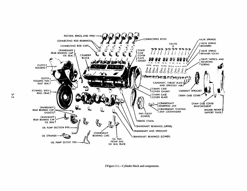
Page 3-2
FFigure 3-1.—Cylinder block and components.

Figure 3-2.—Requirements of a cylinder.
Aluminum is more expensive than cast iron.
Aluminum is not as strong as cast iron.
Because of its softness, it cannot be used on anysurface of the block that is subject to wear. Thisnecessitates the pressing, or casting, of steel
sleeves into the cylinder bores. Threaded holesmust be deeper. This introduces extra designconsiderations and increases production costs.
Aluminum has a much higher expansion ratethan iron when heated. This creates problemswith maintaining tolerances.
The CYLINDERS are bored right into the block. Agood cylinder must be round, not varying in diameter bymore than approximately 0.0005 inch (0.012 mm) (fig.3-2). The diameter of the cylinder must be uniformthroughout its entire length. During normal engineoperation, cylinder walls wear out-of-round, or theymay become cracked and scored if not lubricated orcooled properly. The cylinders on an AIR-COOLEDengine (fig. 3-3) are separate from the crankcase. Theyare made of forged steel. This material is most suitablefor cylinders because of its excellent wearing qualitiesand its ability to withstand high temperatures that air-cooled cylinders obtain. The cylinders have rows ofdeep fins cast into them to dissipate engine heat. Thecylinders are commonly mounted by securing thecylinder head to the crankcase with long studs andsandwiching the cylinders between the two. Anotherway of mounting the cylinders is to bolt them to thecrankcase, and then secure the heads to the cylinders.
A–B–C–D–E–F–G–H–J–K–
O-RING GASKETEXHAUST VALVEINTAKE VALVECYLINDERCYLINDER BARREL NUTLOCK NUTDOME FIN DEFLECTOR (LH)BOLTLOCK WASHERPRIMER NOZZLE ASSEMBLY
L–M–N–P–Q–R–S–T–U–V–
INTAKE VALVE GUIDEEXHAUST VALVE GUIDECAMSHAFT BEARING CAPROCKER SHAFTROCKERROCKER SUPPORT BRACKETWASHERSLOTTED NUTROCKER BOX COVER PLATETAB WASHER
W–X–Y–Z –AA–BB–CC–DD–EE–FF–GG–
VALVE ROCKER COVERBOLTLOCK WASHERWASHERVALVE LOCKVALVE SPRING RETAINEROUTER VALVE SPRINGINTERMEDIATE VALVE SPRINGINNER VALVE SPRINGVALVE RING SEATDOME FIN DEFLECTOR (RH)CMB10054
Figure 3-3.—Air-cooled cylinder.
3-3

Figure 3-4.—Cylinder sleeves.
3-4
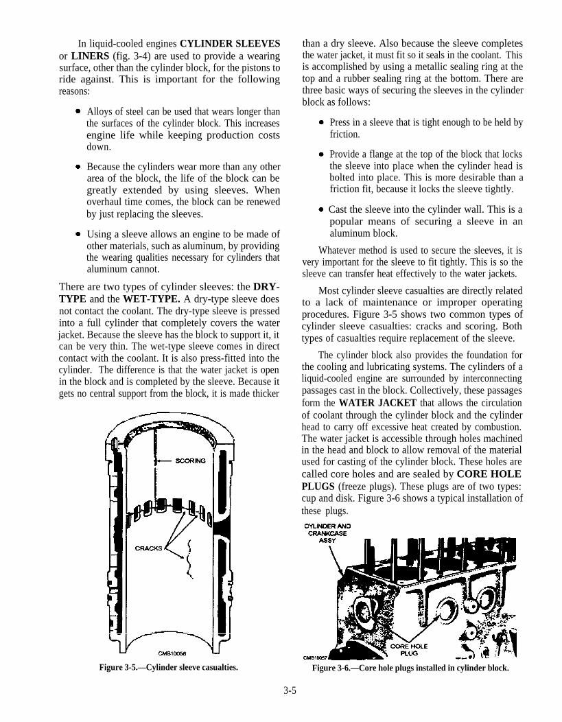
In liquid-cooled engines CYLINDER SLEEVESor LINERS (fig. 3-4) are used to provide a wearingsurface, other than the cylinder block, for the pistons toride against. This is important for the followingreasons:
Alloys of steel can be used that wears longer thanthe surfaces of the cylinder block. This increasesengine life while keeping production costsdown.
Because the cylinders wear more than any otherarea of the block, the life of the block can begreatly extended by using sleeves. Whenoverhaul time comes, the block can be renewedby just replacing the sleeves.
Using a sleeve allows an engine to be made ofother materials, such as aluminum, by providingthe wearing qualities necessary for cylinders thataluminum cannot.
There are two types of cylinder sleeves: the DRY-TYPE and the WET-TYPE. A dry-type sleeve doesnot contact the coolant. The dry-type sleeve is pressedinto a full cylinder that completely covers the waterjacket. Because the sleeve has the block to support it, itcan be very thin. The wet-type sleeve comes in directcontact with the coolant. It is also press-fitted into thecylinder. The difference is that the water jacket is openin the block and is completed by the sleeve. Because itgets no central support from the block, it is made thicker
Figure 3-5.—Cylinder sleeve casualties.
than a dry sleeve. Also because the sleeve completesthe water jacket, it must fit so it seals in the coolant. Thisis accomplished by using a metallic sealing ring at thetop and a rubber sealing ring at the bottom. There arethree basic ways of securing the sleeves in the cylinderblock as follows:
Press in a sleeve that is tight enough to be held byfriction.
Provide a flange at the top of the block that locksthe sleeve into place when the cylinder head isbolted into place. This is more desirable than afriction fit, because it locks the sleeve tightly.
Cast the sleeve into the cylinder wall. This is apopular means of securing a sleeve in analuminum block.
Whatever method is used to secure the sleeves, it isvery important for the sleeve to fit tightly. This is so thesleeve can transfer heat effectively to the water jackets.
Most cylinder sleeve casualties are directly relatedto a lack of maintenance or improper operatingprocedures. Figure 3-5 shows two common types ofcylinder sleeve casualties: cracks and scoring. Bothtypes of casualties require replacement of the sleeve.
The cylinder block also provides the foundation forthe cooling and lubricating systems. The cylinders of aliquid-cooled engine are surrounded by interconnectingpassages cast in the block. Collectively, these passagesform the WATER JACKET that allows the circulationof coolant through the cylinder block and the cylinderhead to carry off excessive heat created by combustion.The water jacket is accessible through holes machinedin the head and block to allow removal of the materialused for casting of the cylinder block. These holes arecalled core holes and are sealed by CORE HOLEPLUGS (freeze plugs). These plugs are of two types:cup and disk. Figure 3-6 shows a typical installation ofthese plugs.
Figure 3-6.—Core hole plugs installed in cylinder block.
3-5
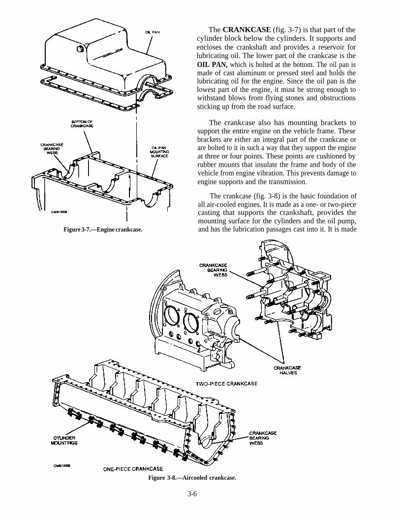
Figure 3-7.—Engine crankcase.
The CRANKCASE (fig. 3-7) is that part of thecylinder block below the cylinders. It supports andencloses the crankshaft and provides a reservoir forlubricating oil. The lower part of the crankcase is theOIL PAN, which is bolted at the bottom. The oil pan ismade of cast aluminum or pressed steel and holds thelubricating oil for the engine. Since the oil pan is thelowest part of the engine, it must be strong enough towithstand blows from flying stones and obstructionssticking up from the road surface.
The crankcase also has mounting brackets tosupport the entire engine on the vehicle frame. Thesebrackets are either an integral part of the crankcase orare bolted to it in such a way that they support the engineat three or four points. These points are cushioned byrubber mounts that insulate the frame and body of thevehicle from engine vibration. This prevents damage toengine supports and the transmission.
The crankcase (fig. 3-8) is the basic foundation ofall air-cooled engines. It is made as a one- or two-piececasting that supports the crankshaft, provides themounting surface for the cylinders and the oil pump,and has the lubrication passages cast into it. It is made
Figure 3-8.—Aircooled crankcase.
3-6

Figure 3-9.—Cylinder heads.
of aluminum since it needs the ability to dissipate largeamounts' of heat. On air-cooled engines, the oil panusually is made of cast aluminum, and it is covered withcooling fins. The oil pan on an air-cooled engine plays akey role in the removal of waste heat from the enginethrough its lubricating oil.
Cylinder Head
The cylinder head (fig. 3-9) provides combustionfor the engine cylinders. It is built to conform to the In liquid-cooled engines. the cylinder (fig. 3-10)arrangement of the valves: L-head, I-head, or others. head is bolted to the top of the cylinder block to close the
Cylinder heads on liquid-cooled engines have beenmade almost exclusively from cast iron until recentyears. Because weight has become an importantconsideration, a large percentage cylinder heads noware being made from aluminum. The cylinder heads onair-cooled engines are made exclusively fromaluminum. This is due to the fact that aluminumconducts heat approximately three times as fast as castiron. This is a critical consideration with air cooling.
Figure 3-10.—Cylinder head for L-head engine.
3-7
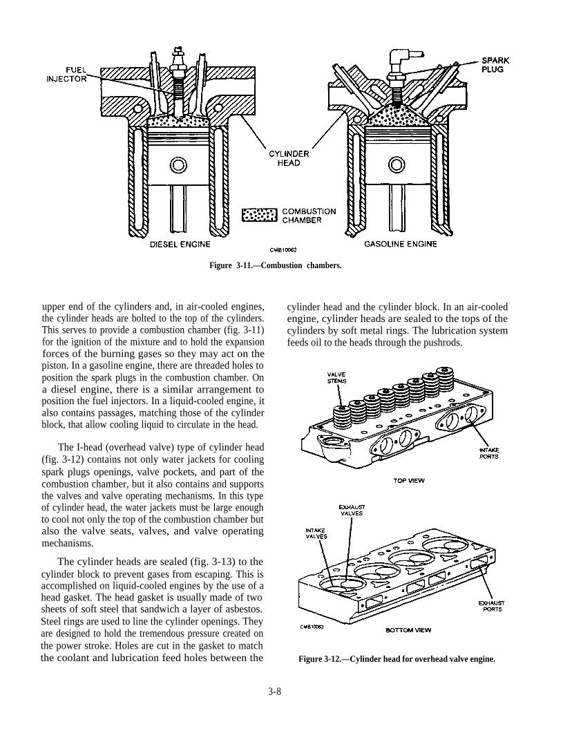
upper end of the cylinders and, in air-cooled engines,the cylinder heads are bolted to the top of the cylinders.This serves to provide a combustion chamber (fig. 3-11)for the ignition of the mixture and to hold the expansionforces of the burning gases so they may act on thepiston. In a gasoline engine, there are threaded holes toposition the spark plugs in the combustion chamber. Ona diesel engine, there is a similar arrangement toposition the fuel injectors. In a liquid-cooled engine, italso contains passages, matching those of the cylinderblock, that allow cooling liquid to circulate in the head.
The I-head (overhead valve) type of cylinder head(fig. 3-12) contains not only water jackets for coolingspark plugs openings, valve pockets, and part of thecombustion chamber, but it also contains and supportsthe valves and valve operating mechanisms. In this typeof cylinder head, the water jackets must be large enoughto cool not only the top of the combustion chamber butalso the valve seats, valves, and valve operatingmechanisms.
The cylinder heads are sealed (fig. 3-13) to thecylinder block to prevent gases from escaping. This isaccomplished on liquid-cooled engines by the use of ahead gasket. The head gasket is usually made of twosheets of soft steel that sandwich a layer of asbestos.Steel rings are used to line the cylinder openings. Theyare designed to hold the tremendous pressure created onthe power stroke. Holes are cut in the gasket to matchthe coolant and lubrication feed holes between the
Figure 3-11.—Combustion chambers.
cylinder head and the cylinder block. In an air-cooledengine, cylinder heads are sealed to the tops of thecylinders by soft metal rings. The lubrication systemfeeds oil to the heads through the pushrods.
Figure 3-12.—Cylinder head for overhead valve engine.
3-8
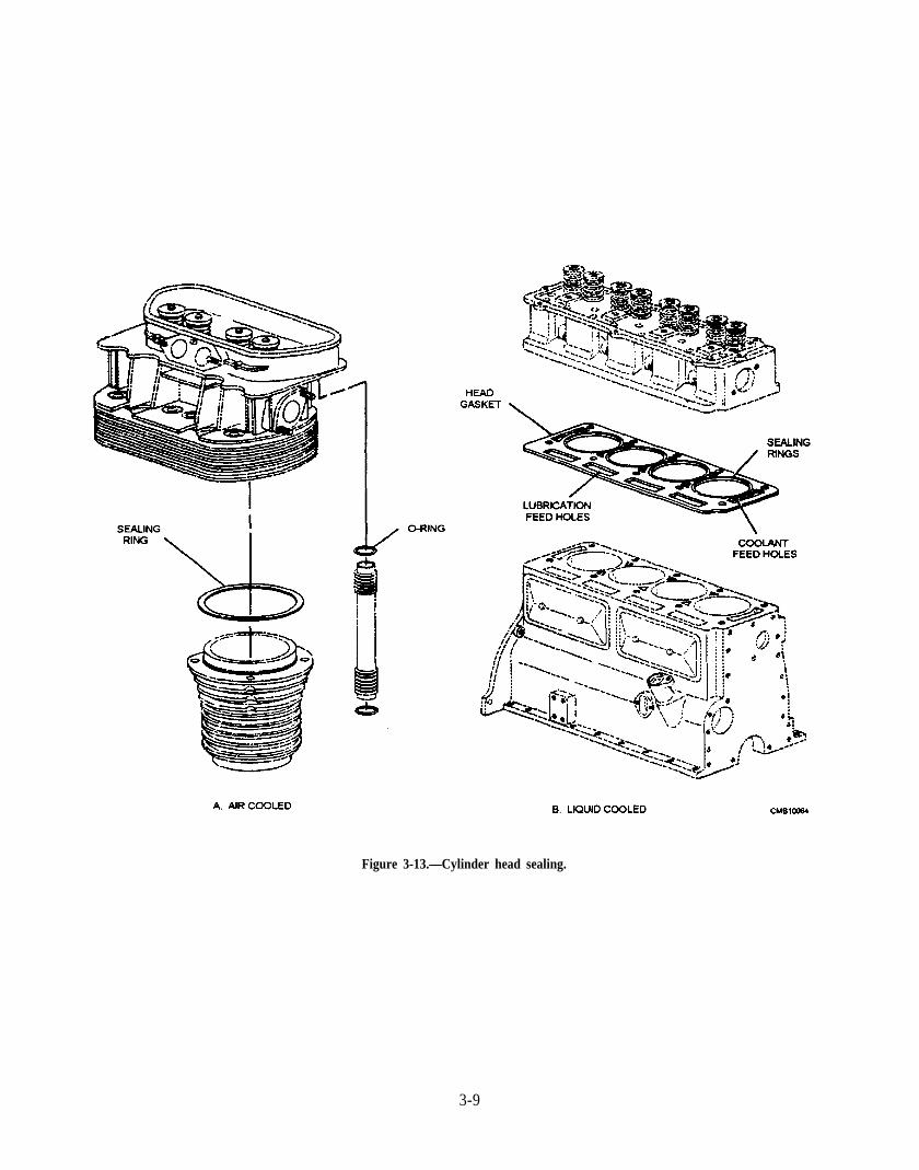
Figure 3-13.—Cylinder head sealing.
3-9
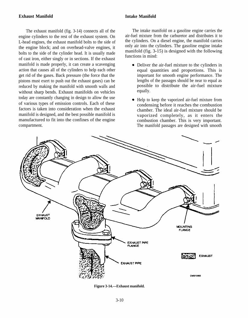
Exhaust Manifold
The exhaust manifold (fig. 3-14) connects all of theengine cylinders to the rest of the exhaust system. OnL-head engines, the exhaust manifold bolts to the side ofthe engine block; and on overhead-valve engines, itbolts to the side of the cylinder head. It is usually madeof cast iron, either singly or in sections. If the exhaustmanifold is made properly, it can create a scavengingaction that causes all of the cylinders to help each otherget rid of the gases. Back pressure (the force that thepistons must exert to push out the exhaust gases) can bereduced by making the manifold with smooth walls andwithout sharp bends. Exhaust manifolds on vehiclestoday are constantly changing in design to allow the useof various types of emission controls. Each of thesefactors is taken into consideration when the exhaustmanifold is designed, and the best possible manifold ismanufactured to fit into the confines of the enginecompartment.
Intake Manifold
The intake manifold on a gasoline engine carries theair-fuel mixture from the carburetor and distributes it tothe cylinders. On a diesel engine, the manifold carriesonly air into the cylinders. The gasoline engine intakemanifold (fig. 3-15) is designed with the followingfunctions in mind:
Deliver the air-fuel mixture to the cylinders inequal quantities and proportions. This isimportant for smooth engine performance. Thelengths of the passages should be near to equal aspossible to distribute the air-fuel mixtureequally.
Help to keep the vaporized air-fuel mixture fromcondensing before it reaches the combustionchamber. The ideal air-fuel mixture should bevaporized completely, as it enters thecombustion chamber. This is very important.The manifold passages are designed with smooth
Figure 3-14.—Exhaust manifold.
3-10
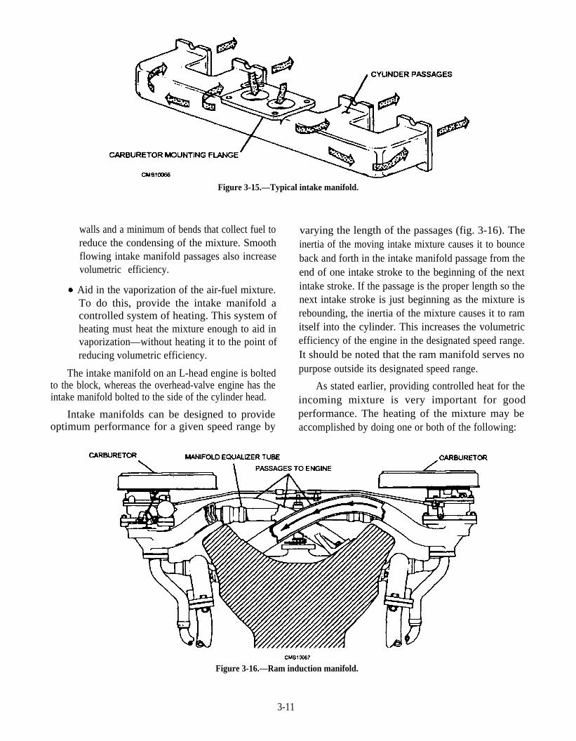
Figure 3-15.—Typical intake manifold.
walls and a minimum of bends that collect fuel toreduce the condensing of the mixture. Smoothflowing intake manifold passages also increasevolumetric efficiency.
Aid in the vaporization of the air-fuel mixture.To do this, provide the intake manifold acontrolled system of heating. This system ofheating must heat the mixture enough to aid invaporization—without heating it to the point ofreducing volumetric efficiency.
The intake manifold on an L-head engine is boltedto the block, whereas the overhead-valve engine has theintake manifold bolted to the side of the cylinder head.
Intake manifolds can be designed to provideoptimum performance for a given speed range by
varying the length of the passages (fig. 3-16). Theinertia of the moving intake mixture causes it to bounceback and forth in the intake manifold passage from theend of one intake stroke to the beginning of the nextintake stroke. If the passage is the proper length so thenext intake stroke is just beginning as the mixture isrebounding, the inertia of the mixture causes it to ramitself into the cylinder. This increases the volumetricefficiency of the engine in the designated speed range.It should be noted that the ram manifold serves nopurpose outside its designated speed range.
As stated earlier, providing controlled heat for theincoming mixture is very important for goodperformance. The heating of the mixture may beaccomplished by doing one or both of the following:
Figure 3-16.—Ram induction manifold.
3-11

Directing a portion of the exhaust through apassage in the intake manifold (fig. 3-17). Theheat from the exhaust transfers and heats themixture. The amount of exhaust that is divertedinto the intake manifold heat passage iscontrolled by the manifold heat control valve.
Directing the engine coolant, which is heated bythe engine, through the intake manifold on itsway to the radiator (fig. 3-18).
Gaskets
Gaskets (fig. 3-19), otherwise known as static seals,are used to form pressure-tight joints betweenstationary members. They are usually made of adeformable material in the shape of a sheet or ring,which conforms to the irregularities in mating surfaceswhen compressed. Steel, aluminum, copper, asbestos,cork, synthetic rubber, paper, and felt are just a few ofthe materials that are used singly or in combination toproduce leakproof joints. The proper material used ingasket construction depends on the temperature, type offluid to be contained, smoothness of mating surfaces,fastener tension, pressure of the substance to beconfined, material used in construction of mating parts,and part clearance relationship. Some of the mostcommon engine gaskets are as follows:
CYLINDER HEAD GASKET which is placedbetween the cylinder head and the cylinder blockto maintain a gastight and coolant-tight seal. It ismade in the form of two thin plates of soft metalwith asbestos tilling between them.
Figure 3-17.—Exhaust-heated intake manifold.
INTAKE AND EXHAUST GASKETS aremade from asbestos and formed to a desiredshape. Some of them are metal-covered andsimilarin construction to a cylinder head gasket.
OIL PAN GASKET is generally made frompressed cork. It may be made in one piece but isoften made as two pieces.
Gaskets also can be formed by using a siliconesealant. This type is formed by applying sealant from asqueeze tube to the mating surfaces and allowing it todry, forming a sealed flexible joint. This type of seal isbecoming more popular on modern vehicles.
Oil Seals
Oil seals used in vehicle assembly are designed toprevent leakage between rotating and non-rotating
Figure 3-18.—Water-heated intake manifold.
3-12
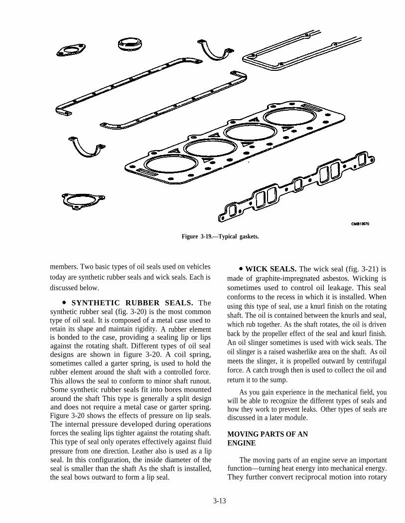
members. Two basic types of oil seals used on vehiclestoday are synthetic rubber seals and wick seals. Each isdiscussed below.
SYNTHETIC RUBBER SEALS. Thesynthetic rubber seal (fig. 3-20) is the most commontype of oil seal. It is composed of a metal case used toretain its shape and maintain rigidity. A rubber elementis bonded to the case, providing a sealing lip or lipsagainst the rotating shaft. Different types of oil sealdesigns are shown in figure 3-20. A coil spring,sometimes called a garter spring, is used to hold therubber element around the shaft with a controlled force.This allows the seal to conform to minor shaft runout.Some synthetic rubber seals fit into bores mountedaround the shaft This type is generally a split designand does not require a metal case or garter spring.Figure 3-20 shows the effects of pressure on lip seals.The internal pressure developed during operationsforces the sealing lips tighter against the rotating shaft.This type of seal only operates effectively against fluidpressure from one direction. Leather also is used as a lipseal. In this configuration, the inside diameter of theseal is smaller than the shaft As the shaft is installed,the seal bows outward to form a lip seal.
Figure 3-19.—Typical gaskets.
WICK SEALS. The wick seal (fig. 3-21) ismade of graphite-impregnated asbestos. Wicking issometimes used to control oil leakage. This sealconforms to the recess in which it is installed. Whenusing this type of seal, use a knurl finish on the rotatingshaft. The oil is contained between the knurls and seal,which rub together. As the shaft rotates, the oil is drivenback by the propeller effect of the seal and knurl finish.An oil slinger sometimes is used with wick seals. Theoil slinger is a raised washerlike area on the shaft. As oilmeets the slinger, it is propelled outward by centrifugalforce. A catch trough then is used to collect the oil andreturn it to the sump.
As you gain experience in the mechanical field, youwill be able to recognize the different types of seals andhow they work to prevent leaks. Other types of seals arediscussed in a later module.
MOVING PARTS OF ANENGINE
The moving parts of an engine serve an importantfunction—turning heat energy into mechanical energy.They further convert reciprocal motion into rotary
3-13
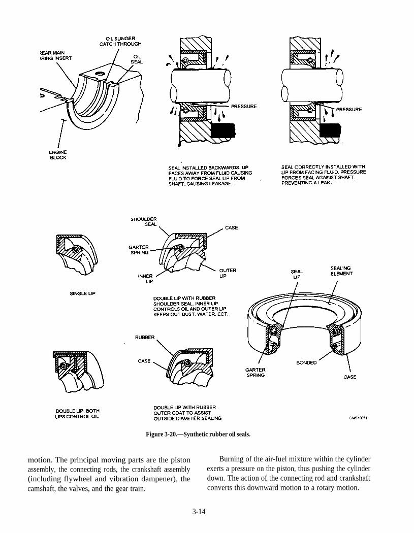
Figure 3-20.—Synthetic rubber oil seals.
motion. The principal moving parts are the piston Burning of the air-fuel mixture within the cylinderassembly, the connecting rods, the crankshaft assembly exerts a pressure on the piston, thus pushing the cylinder(including flywheel and vibration dampener), the down. The action of the connecting rod and crankshaftcamshaft, the valves, and the gear train. converts this downward motion to a rotary motion.
3-14
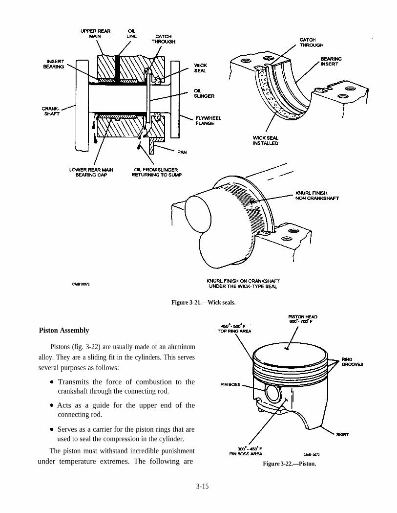
Piston Assembly
Figure 3-21.—Wick seals.
Pistons (fig. 3-22) are usually made of an aluminumalloy. They are a sliding fit in the cylinders. This servesseveral purposes as follows:
Transmits the force of combustion to thecrankshaft through the connecting rod.
Acts as a guide for the upper end of theconnecting rod.
Serves as a carrier for the piston rings that areused to seal the compression in the cylinder.
The piston must withstand incredible punishmentunder temperature extremes. The following are Figure 3-22.—Piston.
3-15
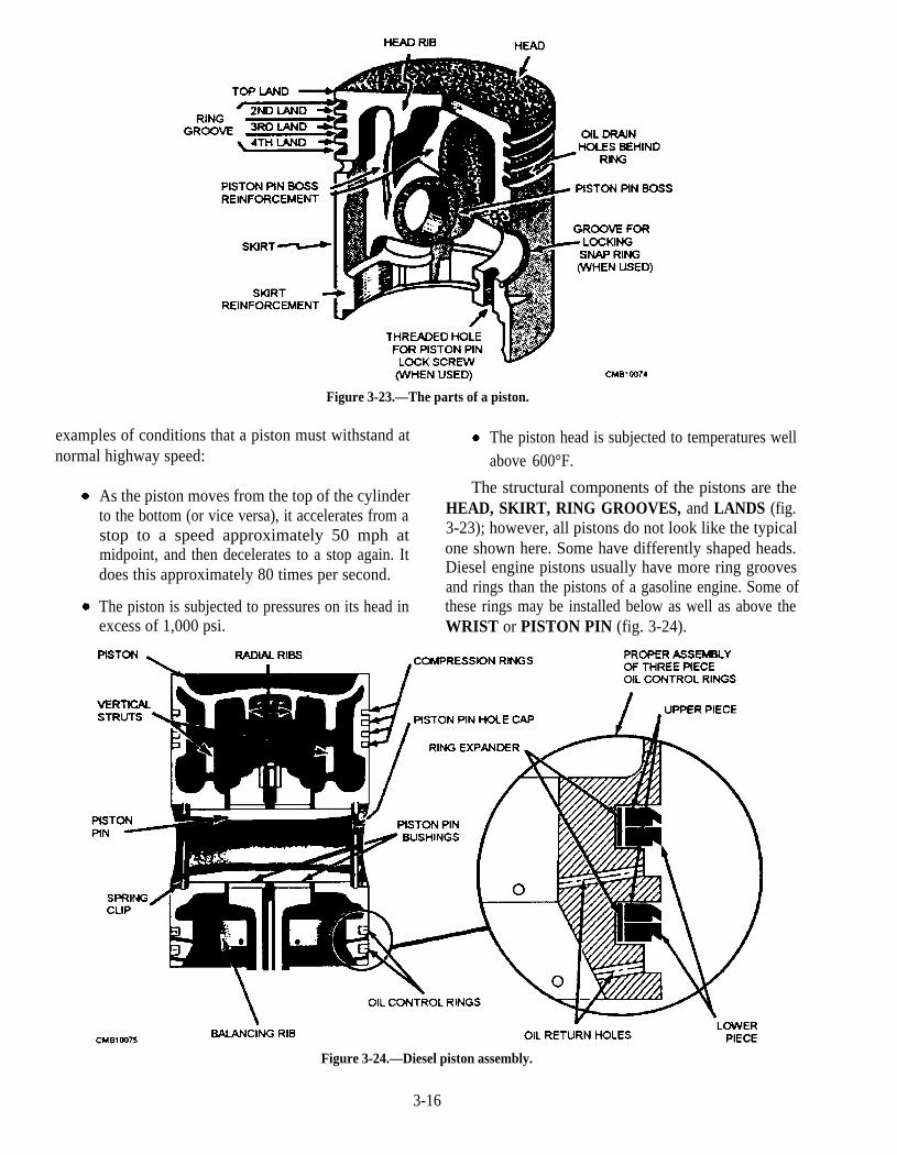
Figure 3-23.—The parts of a piston.
examples of conditions that a piston must withstand at The piston head is subjected to temperatures wellnormal highway speed: above 600°F.
As the piston moves from the top of the cylinder The structural components of the pistons are the
to the bottom (or vice versa), it accelerates from a HEAD, SKIRT, RING GROOVES, and LANDS (fig.
stop to a speed approximately 50 mph at 3-23); however, all pistons do not look like the typical
midpoint, and then decelerates to a stop again. It one shown here. Some have differently shaped heads.
does this approximately 80 times per second. Diesel engine pistons usually have more ring groovesand rings than the pistons of a gasoline engine. Some of
The piston is subjected to pressures on its head in these rings may be installed below as well as above theexcess of 1,000 psi. WRIST or PISTON PIN (fig. 3-24).
Figure 3-24.—Diesel piston assembly.
3-16
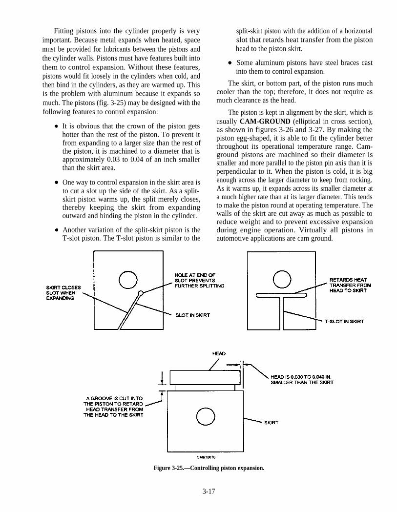
Fitting pistons into the cylinder properly is veryimportant. Because metal expands when heated, spacemust be provided for lubricants between the pistons andthe cylinder walls. Pistons must have features built intothem to control expansion. Without these features,pistons would fit loosely in the cylinders when cold, andthen bind in the cylinders, as they are warmed up. Thisis the problem with aluminum because it expands somuch. The pistons (fig. 3-25) may be designed with thefollowing features to control expansion:
It is obvious that the crown of the piston getshotter than the rest of the piston. To prevent itfrom expanding to a larger size than the rest ofthe piston, it is machined to a diameter that isapproximately 0.03 to 0.04 of an inch smallerthan the skirt area.
One way to control expansion in the skirt area isto cut a slot up the side of the skirt. As a split-skirt piston warms up, the split merely closes,thereby keeping the skirt from expandingoutward and binding the piston in the cylinder.
Another variation of the split-skirt piston is theT-slot piston. The T-slot piston is similar to the
split-skirt piston with the addition of a horizontalslot that retards heat transfer from the pistonhead to the piston skirt.
Some aluminum pistons have steel braces castinto them to control expansion.
The skirt, or bottom part, of the piston runs muchcooler than the top; therefore, it does not require asmuch clearance as the head.
The piston is kept in alignment by the skirt, which isusually CAM-GROUND (elliptical in cross section),as shown in figures 3-26 and 3-27. By making thepiston egg-shaped, it is able to fit the cylinder betterthroughout its operational temperature range. Cam-ground pistons are machined so their diameter issmaller and more parallel to the piston pin axis than it isperpendicular to it. When the piston is cold, it is bigenough across the larger diameter to keep from rocking.As it warms up, it expands across its smaller diameter ata much higher rate than at its larger diameter. This tendsto make the piston round at operating temperature. Thewalls of the skirt are cut away as much as possible toreduce weight and to prevent excessive expansionduring engine operation. Virtually all pistons inautomotive applications are cam ground.
Figure 3-25.—Controlling piston expansion.
3-17
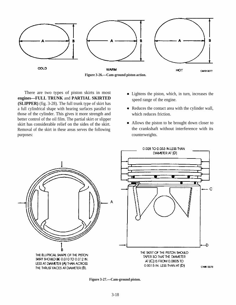
Figure 3-26.—Cam-ground piston action.
There are two types of piston skirts in mostengines—FULL TRUNK and PARTIAL SKIRTED(SLIPPER) (fig. 3-28). The full trunk type of skirt hasa full cylindrical shape with hearing surfaces parallel tothose of the cylinder. This gives it more strength andbetter control of the oil film. The partial skirt or slipperskirt has considerable relief on the sides of the skirt.Removal of the skirt in these areas serves the followingpurposes:
Lightens the piston, which, in turn, increases thespeed range of the engine.
Reduces the contact area with the cylinder wall,which reduces friction.
Allows the piston to be brought down closer tothe crankshaft without interference with itscounterweights.
Figure 3-27.—Cam-ground piston.
3-18
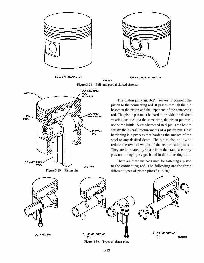
Figure 3-28.—Full- and partial-skirted pistons.
The piston pin (fig. 3-29) serves to connect thepiston to the connecting rod. It passes through the pinbosses in the piston and the upper end of the connectingrod. The piston pin must be hard to provide the desiredwearing qualities. At the same time, the piston pin mustnot be too brittle. A case-hardened steel pin is the best tosatisfy the overall requirements of a piston pin. Casehardening is a process that hardens the surface of thesteel to any desired depth. The pin is also hollow toreduce the overall weight of the reciprocating mass.They are lubricated by splash from the crankcase or bypressure through passages bored in the connecting rod.
There are three methods used for fastening a pistonto the connecting rod. The following are the three
Figure 3-29.—Piston pin. different types of piston pins (fig. 3-30):
Figure 3-30.—Types of piston pins.
3-19
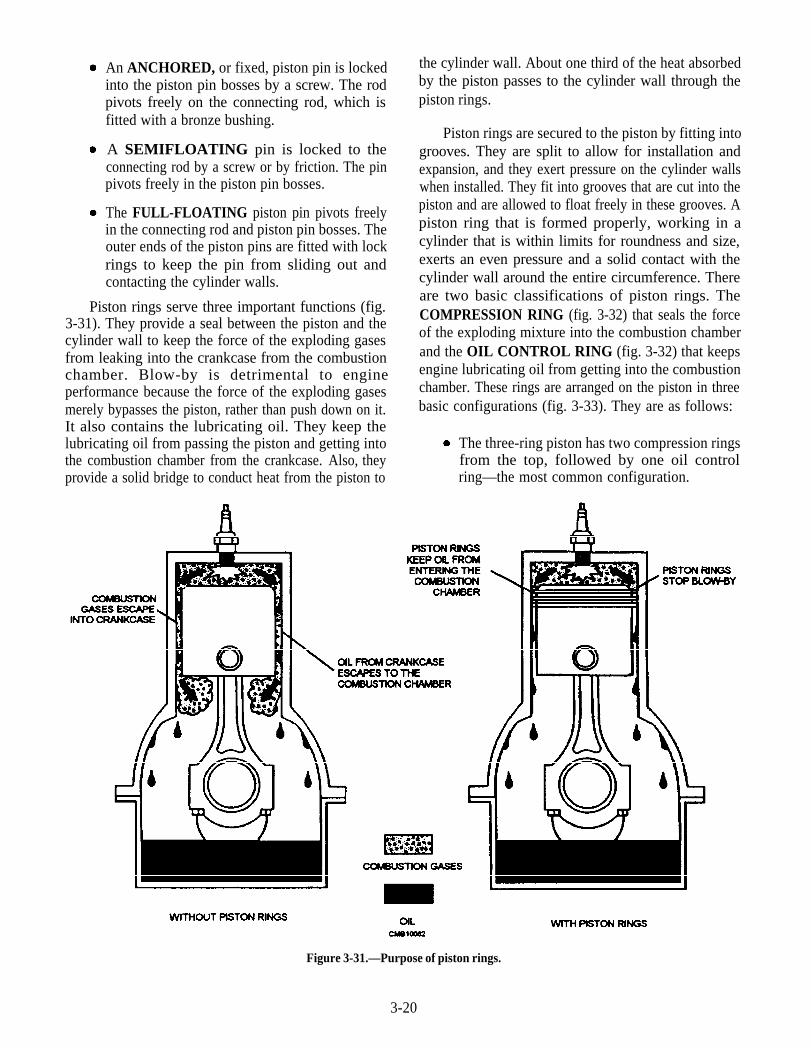
An ANCHORED, or fixed, piston pin is lockedinto the piston pin bosses by a screw. The rodpivots freely on the connecting rod, which isfitted with a bronze bushing.
A SEMIFLOATING pin is locked to theconnecting rod by a screw or by friction. The pinpivots freely in the piston pin bosses.
The FULL-FLOATING piston pin pivots freelyin the connecting rod and piston pin bosses. Theouter ends of the piston pins are fitted with lockrings to keep the pin from sliding out andcontacting the cylinder walls.
Piston rings serve three important functions (fig.3-31). They provide a seal between the piston and thecylinder wall to keep the force of the exploding gasesfrom leaking into the crankcase from the combustionchamber. Blow-by is detrimental to engineperformance because the force of the exploding gasesmerely bypasses the piston, rather than push down on it.It also contains the lubricating oil. They keep thelubricating oil from passing the piston and getting intothe combustion chamber from the crankcase. Also, theyprovide a solid bridge to conduct heat from the piston to
the cylinder wall. About one third of the heat absorbedby the piston passes to the cylinder wall through thepiston rings.
Piston rings are secured to the piston by fitting intogrooves. They are split to allow for installation andexpansion, and they exert pressure on the cylinder wallswhen installed. They fit into grooves that are cut into thepiston and are allowed to float freely in these grooves. Apiston ring that is formed properly, working in acylinder that is within limits for roundness and size,exerts an even pressure and a solid contact with thecylinder wall around the entire circumference. Thereare two basic classifications of piston rings. TheCOMPRESSION RING (fig. 3-32) that seals the forceof the exploding mixture into the combustion chamberand the OIL CONTROL RING (fig. 3-32) that keepsengine lubricating oil from getting into the combustionchamber. These rings are arranged on the piston in threebasic configurations (fig. 3-33). They are as follows:
The three-ring piston has two compression ringsfrom the top, followed by one oil controlring—the most common configuration.
Figure 3-31.—Purpose of piston rings.
3-20
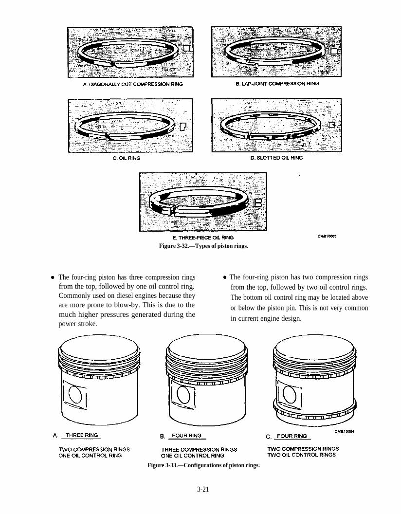
Figure 3-32.—Types of piston rings.
The four-ring piston has three compression rings The four-ring piston has two compression ringsfrom the top, followed by one oil control ring. from the top, followed by two oil control rings.Commonly used on diesel engines because they The bottom oil control ring may be located aboveare more prone to blow-by. This is due to themuch higher pressures generated during the
or below the piston pin. This is not very common
power stroke.in current engine design.
Figure 3-33.—Configurations of piston rings.
3-21
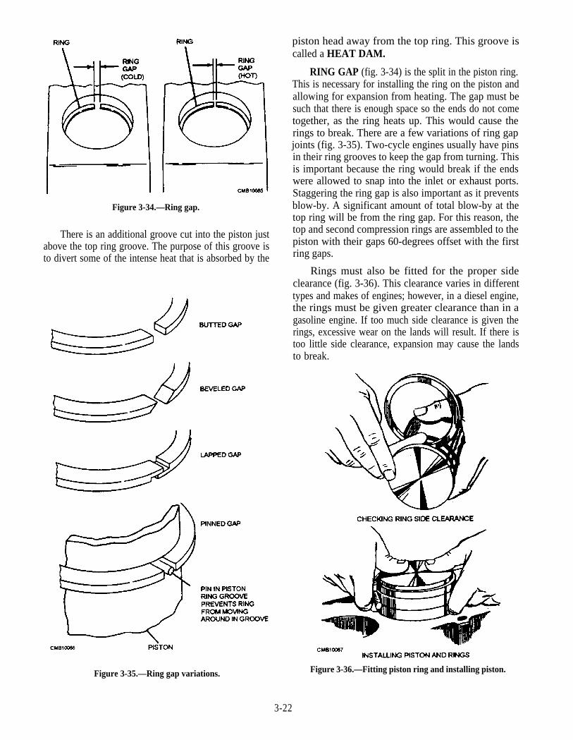
Figure 3-34.—Ring gap.
There is an additional groove cut into the piston justabove the top ring groove. The purpose of this groove isto divert some of the intense heat that is absorbed by the
piston head away from the top ring. This groove iscalled a HEAT DAM.
RING GAP (fig. 3-34) is the split in the piston ring.This is necessary for installing the ring on the piston andallowing for expansion from heating. The gap must besuch that there is enough space so the ends do not cometogether, as the ring heats up. This would cause therings to break. There are a few variations of ring gapjoints (fig. 3-35). Two-cycle engines usually have pinsin their ring grooves to keep the gap from turning. Thisis important because the ring would break if the endswere allowed to snap into the inlet or exhaust ports.Staggering the ring gap is also important as it preventsblow-by. A significant amount of total blow-by at thetop ring will be from the ring gap. For this reason, thetop and second compression rings are assembled to thepiston with their gaps 60-degrees offset with the firstring gaps.
Rings must also be fitted for the proper sideclearance (fig. 3-36). This clearance varies in differenttypes and makes of engines; however, in a diesel engine,the rings must be given greater clearance than in agasoline engine. If too much side clearance is given therings, excessive wear on the lands will result. If there istoo little side clearance, expansion may cause the landsto break.
Figure 3-35.—Ring gap variations. Figure 3-36.—Fitting piston ring and installing piston.
3-22
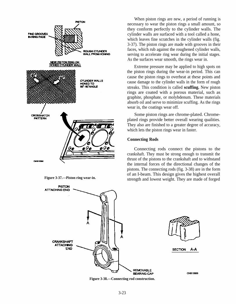
When piston rings are new, a period of running isnecessary to wear the piston rings a small amount, sothey conform perfectly to the cylinder walls. Thecylinder walls are surfaced with a tool called a hone,which leaves fine scratches in the cylinder walls (fig.3-37). The piston rings are made with grooves in theirfaces, which rub against the roughened cylinder walls,serving to accelerate ring wear during the initial stages.As the surfaces wear smooth, the rings wear in.
Extreme pressure may be applied to high spots onthe piston rings during the wear-in period. This cancause the piston rings to overheat at these points andcause damage to the cylinder walls in the form of roughstreaks. This condition is called scuffing. New pistonrings are coated with a porous material, such asgraphite, phosphate, or molybdenum. These materialsabsorb oil and serve to minimize scuffing. As the ringswear in, the coatings wear off.
Some piston rings are chrome-plated. Chrome-plated rings provide better overall wearing qualities.They also are finished to a greater degree of accuracy,which lets the piston rings wear in faster.
Figure 3-37.—Piston ring wear-in.
Connecting Rods
Connecting rods connect the pistons to thecrankshaft. They must be strong enough to transmit thethrust of the pistons to the crankshaft and to withstandthe internal forces of the directional changes of thepistons. The connecting rods (fig. 3-38) are in the formof an I-beam. This design gives the highest overallstrength and lowest weight. They are made of forged
Figure 3-38.—Connecting rod construction.
3-23
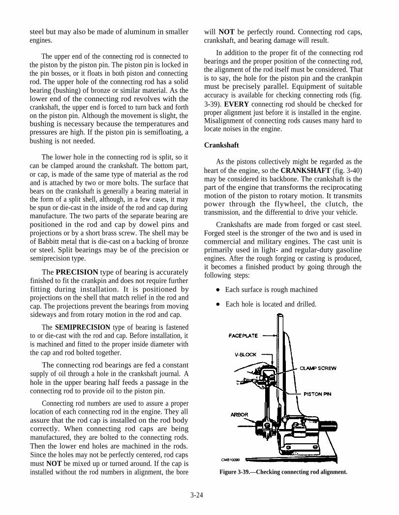
steel but may also be made of aluminum in smallerengines.
The upper end of the connecting rod is connected tothe piston by the piston pin. The piston pin is locked inthe pin bosses, or it floats in both piston and connectingrod. The upper hole of the connecting rod has a solidbearing (bushing) of bronze or similar material. As thelower end of the connecting rod revolves with thecrankshaft, the upper end is forced to turn back and forthon the piston pin. Although the movement is slight, thebushing is necessary because the temperatures andpressures are high. If the piston pin is semifloating, abushing is not needed.
The lower hole in the connecting rod is split, so itcan be clamped around the crankshaft. The bottom part,or cap, is made of the same type of material as the rodand is attached by two or more bolts. The surface thatbears on the crankshaft is generally a bearing material inthe form of a split shell, although, in a few cases, it maybe spun or die-cast in the inside of the rod and cap duringmanufacture. The two parts of the separate bearing arepositioned in the rod and cap by dowel pins andprojections or by a short brass screw. The shell may beof Babbitt metal that is die-cast on a backing of bronzeor steel. Split bearings may be of the precision orsemiprecision type.
The PRECISION type of bearing is accuratelyfinished to fit the crankpin and does not require furtherfitting during installation. It is positioned byprojections on the shell that match relief in the rod andcap. The projections prevent the bearings from movingsideways and from rotary motion in the rod and cap.
The SEMIPRECISION type of bearing is fastenedto or die-cast with the rod and cap. Before installation, itis machined and fitted to the proper inside diameter withthe cap and rod bolted together.
The connecting rod bearings are fed a constantsupply of oil through a hole in the crankshaft journal. Ahole in the upper bearing half feeds a passage in theconnecting rod to provide oil to the piston pin.
Connecting rod numbers are used to assure a properlocation of each connecting rod in the engine. They allassure that the rod cap is installed on the rod bodycorrectly. When connecting rod caps are beingmanufactured, they are bolted to the connecting rods.Then the lower end holes are machined in the rods.Since the holes may not be perfectly centered, rod capsmust NOT be mixed up or turned around. If the cap isinstalled without the rod numbers in alignment, the bore
will NOT be perfectly round. Connecting rod caps,crankshaft, and bearing damage will result.
In addition to the proper fit of the connecting rodbearings and the proper position of the connecting rod,the alignment of the rod itself must be considered. Thatis to say, the hole for the piston pin and the crankpinmust be precisely parallel. Equipment of suitableaccuracy is available for checking connecting rods (fig.3-39). EVERY connecting rod should be checked forproper alignment just before it is installed in the engine.Misalignment of connecting rods causes many hard tolocate noises in the engine.
Crankshaft
As the pistons collectively might be regarded as theheart of the engine, so the CRANKSHAFT (fig. 3-40)may be considered its backbone. The crankshaft is thepart of the engine that transforms the reciprocatingmotion of the piston to rotary motion. It transmitspower through the flywheel, the clutch, thetransmission, and the differential to drive your vehicle.
Crankshafts are made from forged or cast steel.Forged steel is the stronger of the two and is used incommercial and military engines. The cast unit isprimarily used in light- and regular-duty gasolineengines. After the rough forging or casting is produced,it becomes a finished product by going through thefollowing steps:
Each hole is located and drilled.
Each surface is rough machined
Figure 3-39.—Checking connecting rod alignment.
3-24
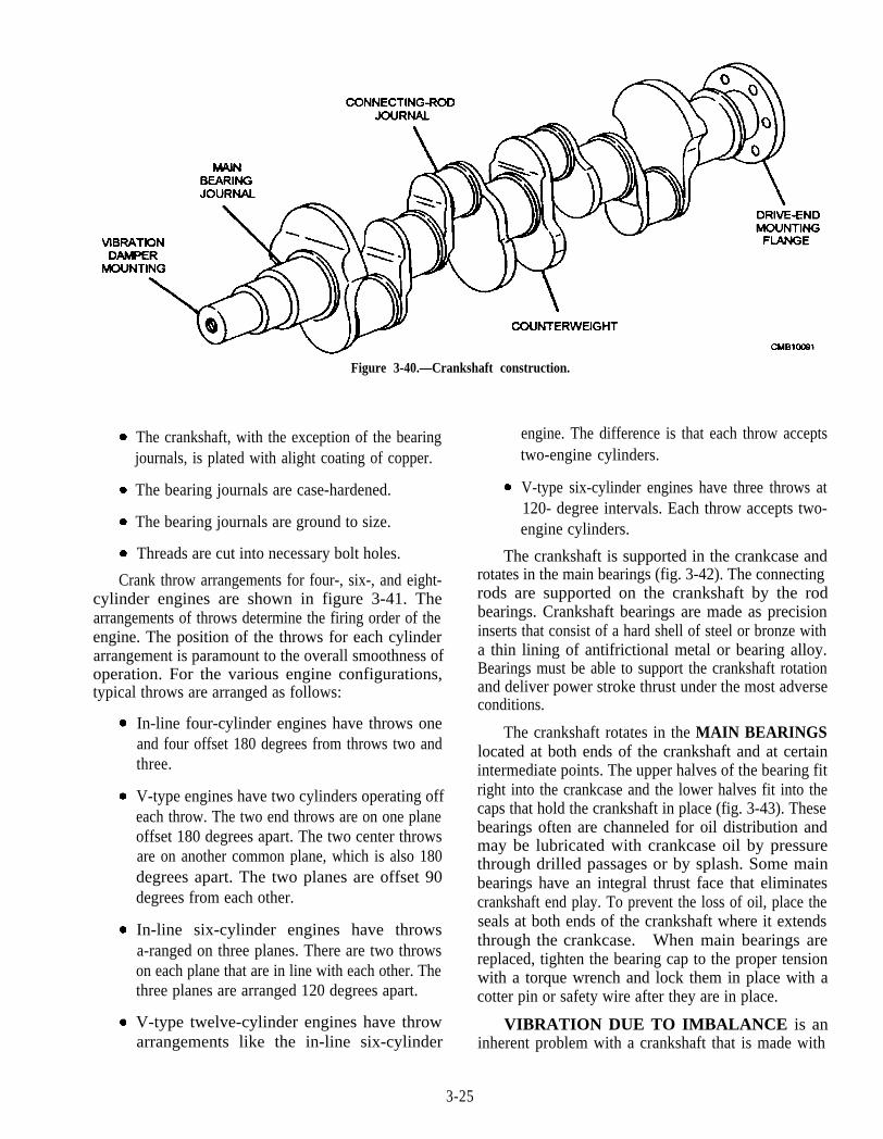
Figure 3-40.—Crankshaft construction.
The crankshaft, with the exception of the bearingjournals, is plated with alight coating of copper.
The bearing journals are case-hardened.
The bearing journals are ground to size.
Threads are cut into necessary bolt holes.
Crank throw arrangements for four-, six-, and eight-cylinder engines are shown in figure 3-41. Thearrangements of throws determine the firing order of theengine. The position of the throws for each cylinderarrangement is paramount to the overall smoothness ofoperation. For the various engine configurations,typical throws are arranged as follows:
In-line four-cylinder engines have throws oneand four offset 180 degrees from throws two andthree.
V-type engines have two cylinders operating offeach throw. The two end throws are on one planeoffset 180 degrees apart. The two center throwsare on another common plane, which is also 180degrees apart. The two planes are offset 90degrees from each other.
In-line six-cylinder engines have throwsa-ranged on three planes. There are two throwson each plane that are in line with each other. Thethree planes are arranged 120 degrees apart.
V-type twelve-cylinder engines have throwarrangements like the in-line six-cylinder
engine. The difference is that each throw acceptstwo-engine cylinders.
V-type six-cylinder engines have three throws at120- degree intervals. Each throw accepts two-engine cylinders.
The crankshaft is supported in the crankcase androtates in the main bearings (fig. 3-42). The connectingrods are supported on the crankshaft by the rodbearings. Crankshaft bearings are made as precisioninserts that consist of a hard shell of steel or bronze witha thin lining of antifrictional metal or bearing alloy.Bearings must be able to support the crankshaft rotationand deliver power stroke thrust under the most adverseconditions.
The crankshaft rotates in the MAIN BEARINGSlocated at both ends of the crankshaft and at certainintermediate points. The upper halves of the bearing fitright into the crankcase and the lower halves fit into thecaps that hold the crankshaft in place (fig. 3-43). Thesebearings often are channeled for oil distribution andmay be lubricated with crankcase oil by pressurethrough drilled passages or by splash. Some mainbearings have an integral thrust face that eliminatescrankshaft end play. To prevent the loss of oil, place theseals at both ends of the crankshaft where it extendsthrough the crankcase. When main bearings arereplaced, tighten the bearing cap to the proper tensionwith a torque wrench and lock them in place with acotter pin or safety wire after they are in place.
VIBRATION DUE TO IMBALANCE is aninherent problem with a crankshaft that is made with
3-25

Figure 3-41.—Crankshaft throw arrangements.
3-26

Figure 3-43.—Typical insert bearing installation.
3-27

offset throws. The weight of the throws tend to makethe crankshaft rotate elliptically. This is aggravatedfurther by the weight of the piston and the connectingrod. To eliminate the problem, position the weightsalong the crankshaft. One weight is placed 180 degreesaway from each throw. They are called counterweightsand are usually part of the crankshaft but may be aseparate bolt on items on small engines.
The crankshaft has a tendency to bend slightlywhen subjected to tremendous thrust from the piston.This deflection of the rotating member causes vibration.This VIBRATION DUE TO DEFLECTION isminimized by heavy crankshaft construction andsufficient support along its length by bearings.
TORSIONAL VIBRATION occurs when thecrankshaft twists because of the power stroke thrusts. Itis caused by the cylinders furthest away from the
crankshaft output. As these cylinders apply thrust to thecrankshaft, it twists and the thrust decreases. Thetwisting and unwinding of the crankshaft produces avibration. The use of a vibration damper at the end ofthe crankshaft opposite the output acts to absorbtorsional vibration.
Vibration Damper
The power impulses of an engine tend to set uptorsional vibration in the crankshaft. If this torsionalvibration were not controlled, the crankshaft mightactually break at certain speeds; a vibration dampermounted on the front of the crankshaft controls thisvibration.
There are a few variations of the vibration damper(fig. 3-44), but they all accomplish their task basically in
Figure 3-44.—Vibration damper.
3-28
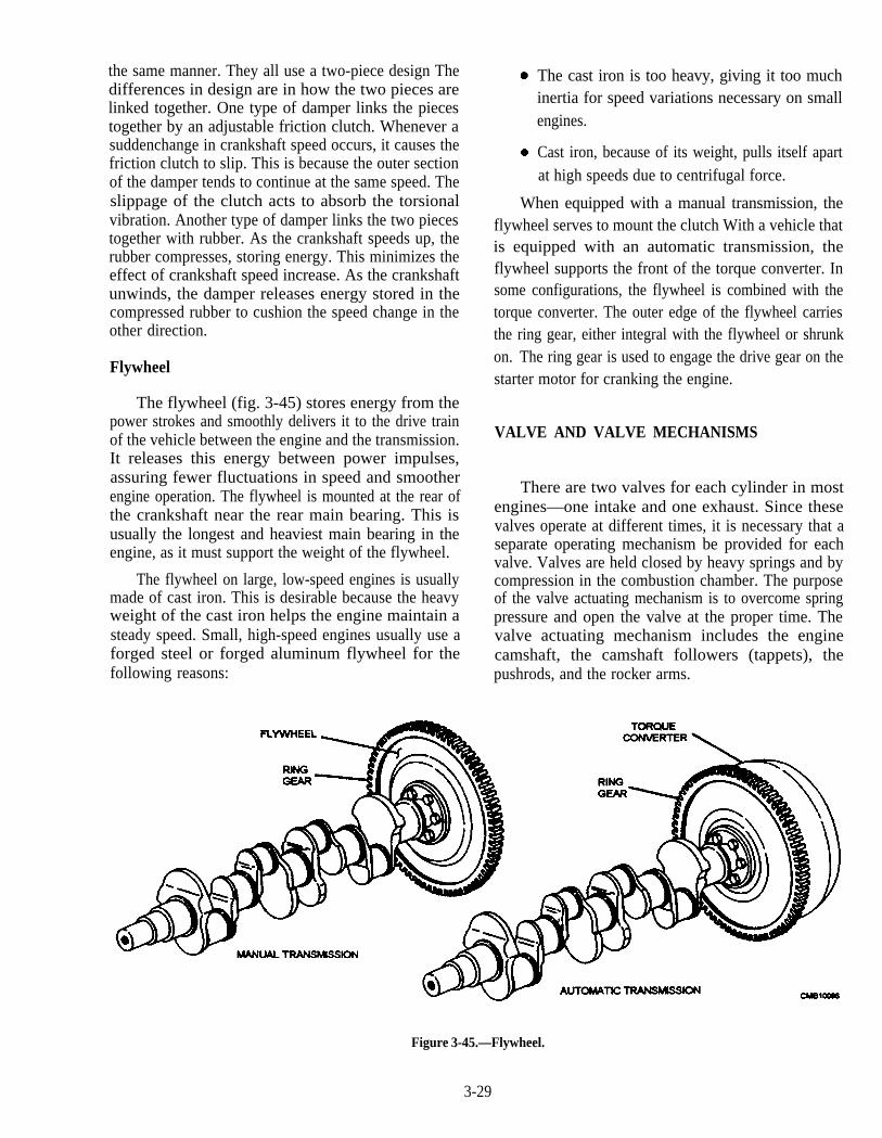
the same manner. They all use a two-piece design Thedifferences in design are in how the two pieces arelinked together. One type of damper links the piecestogether by an adjustable friction clutch. Whenever asuddenchange in crankshaft speed occurs, it causes thefriction clutch to slip. This is because the outer sectionof the damper tends to continue at the same speed. Theslippage of the clutch acts to absorb the torsionalvibration. Another type of damper links the two piecestogether with rubber. As the crankshaft speeds up, therubber compresses, storing energy. This minimizes theeffect of crankshaft speed increase. As the crankshaftunwinds, the damper releases energy stored in thecompressed rubber to cushion the speed change in theother direction.
Flywheel
The flywheel (fig. 3-45) stores energy from thepower strokes and smoothly delivers it to the drive trainof the vehicle between the engine and the transmission.It releases this energy between power impulses,assuring fewer fluctuations in speed and smootherengine operation. The flywheel is mounted at the rear ofthe crankshaft near the rear main bearing. This isusually the longest and heaviest main bearing in theengine, as it must support the weight of the flywheel.
The flywheel on large, low-speed engines is usuallymade of cast iron. This is desirable because the heavyweight of the cast iron helps the engine maintain asteady speed. Small, high-speed engines usually use aforged steel or forged aluminum flywheel for thefollowing reasons:
The cast iron is too heavy, giving it too muchinertia for speed variations necessary on smallengines.
Cast iron, because of its weight, pulls itself apartat high speeds due to centrifugal force.
When equipped with a manual transmission, theflywheel serves to mount the clutch With a vehicle thatis equipped with an automatic transmission, theflywheel supports the front of the torque converter. Insome configurations, the flywheel is combined with thetorque converter. The outer edge of the flywheel carriesthe ring gear, either integral with the flywheel or shrunkon. The ring gear is used to engage the drive gear on thestarter motor for cranking the engine.
VALVE AND VALVE MECHANISMS
There are two valves for each cylinder in mostengines—one intake and one exhaust. Since thesevalves operate at different times, it is necessary that aseparate operating mechanism be provided for eachvalve. Valves are held closed by heavy springs and bycompression in the combustion chamber. The purposeof the valve actuating mechanism is to overcome springpressure and open the valve at the proper time. Thevalve actuating mechanism includes the enginecamshaft, the camshaft followers (tappets), thepushrods, and the rocker arms.
Figure 3-45.—Flywheel.
3-29
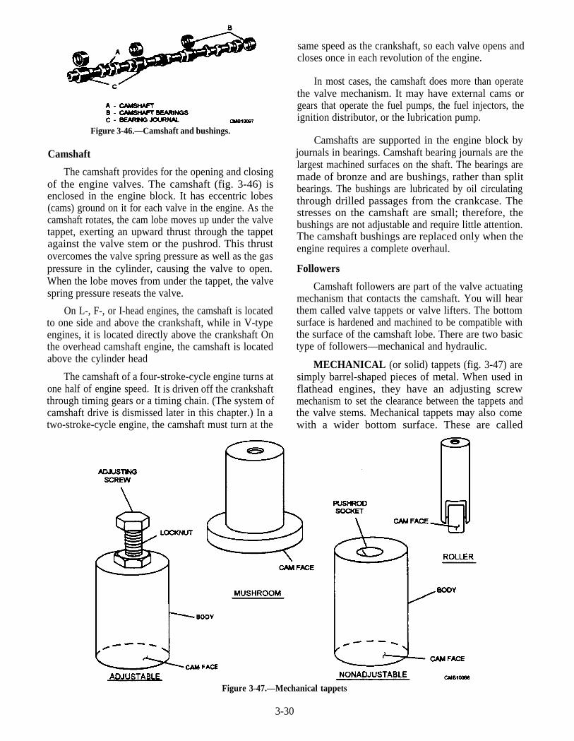
Figure 3-46.—Camshaft and bushings.
Camshaft
The camshaft provides for the opening and closingof the engine valves. The camshaft (fig. 3-46) isenclosed in the engine block. It has eccentric lobes(cams) ground on it for each valve in the engine. As thecamshaft rotates, the cam lobe moves up under the valvetappet, exerting an upward thrust through the tappetagainst the valve stem or the pushrod. This thrustovercomes the valve spring pressure as well as the gaspressure in the cylinder, causing the valve to open.When the lobe moves from under the tappet, the valvespring pressure reseats the valve.
On L-, F-, or I-head engines, the camshaft is locatedto one side and above the crankshaft, while in V-typeengines, it is located directly above the crankshaft Onthe overhead camshaft engine, the camshaft is locatedabove the cylinder head
The camshaft of a four-stroke-cycle engine turns atone half of engine speed. It is driven off the crankshaftthrough timing gears or a timing chain. (The system ofcamshaft drive is dismissed later in this chapter.) In atwo-stroke-cycle engine, the camshaft must turn at the
same speed as the crankshaft, so each valve opens andcloses once in each revolution of the engine.
In most cases, the camshaft does more than operatethe valve mechanism. It may have external cams orgears that operate the fuel pumps, the fuel injectors, theignition distributor, or the lubrication pump.
Camshafts are supported in the engine block byjournals in bearings. Camshaft bearing journals are thelargest machined surfaces on the shaft. The bearings aremade of bronze and are bushings, rather than splitbearings. The bushings are lubricated by oil circulatingthrough drilled passages from the crankcase. Thestresses on the camshaft are small; therefore, thebushings are not adjustable and require little attention.The camshaft bushings are replaced only when theengine requires a complete overhaul.
Followers
Camshaft followers are part of the valve actuatingmechanism that contacts the camshaft. You will hearthem called valve tappets or valve lifters. The bottomsurface is hardened and machined to be compatible withthe surface of the camshaft lobe. There are two basictype of followers—mechanical and hydraulic.
MECHANICAL (or solid) tappets (fig. 3-47) aresimply barrel-shaped pieces of metal. When used inflathead engines, they have an adjusting screwmechanism to set the clearance between the tappets andthe valve stems. Mechanical tappets may also comewith a wider bottom surface. These are called
Figure 3-47.—Mechanical tappets
3-30
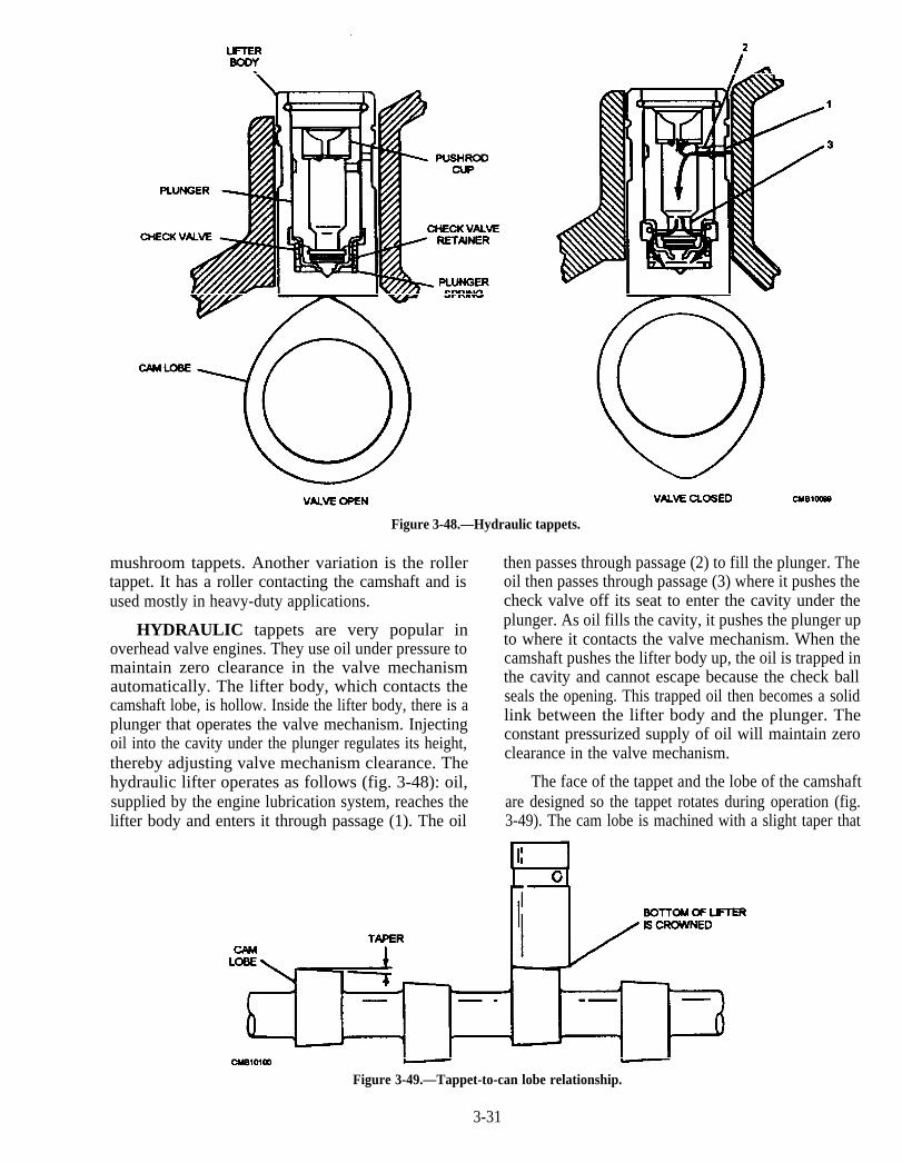
Figure 3-48.—Hydraulic tappets.
mushroom tappets. Another variation is the rollertappet. It has a roller contacting the camshaft and isused mostly in heavy-duty applications.
HYDRAULIC tappets are very popular inoverhead valve engines. They use oil under pressure tomaintain zero clearance in the valve mechanismautomatically. The lifter body, which contacts thecamshaft lobe, is hollow. Inside the lifter body, there is aplunger that operates the valve mechanism. Injectingoil into the cavity under the plunger regulates its height,thereby adjusting valve mechanism clearance. Thehydraulic lifter operates as follows (fig. 3-48): oil,supplied by the engine lubrication system, reaches thelifter body and enters it through passage (1). The oil
then passes through passage (2) to fill the plunger. Theoil then passes through passage (3) where it pushes thecheck valve off its seat to enter the cavity under theplunger. As oil fills the cavity, it pushes the plunger upto where it contacts the valve mechanism. When thecamshaft pushes the lifter body up, the oil is trapped inthe cavity and cannot escape because the check ballseals the opening. This trapped oil then becomes a solidlink between the lifter body and the plunger. Theconstant pressurized supply of oil will maintain zeroclearance in the valve mechanism.
The face of the tappet and the lobe of the camshaftare designed so the tappet rotates during operation (fig.3-49). The cam lobe is machined with a slight taper that
Figure 3-49.—Tappet-to-can lobe relationship.
3-31
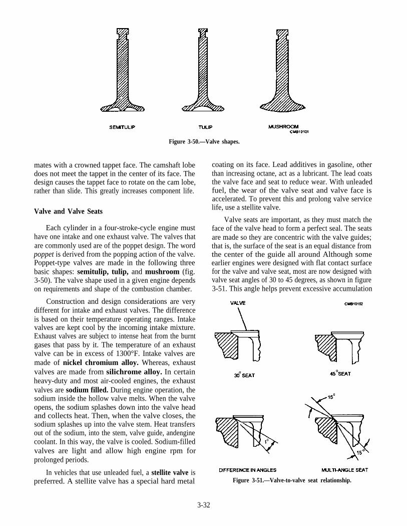
Figure 3-50.—Valve shapes.
mates with a crowned tappet face. The camshaft lobedoes not meet the tappet in the center of its face. Thedesign causes the tappet face to rotate on the cam lobe,rather than slide. This greatly increases component life.
Valve and Valve Seats
Each cylinder in a four-stroke-cycle engine musthave one intake and one exhaust valve. The valves thatare commonly used are of the poppet design. The wordpoppet is derived from the popping action of the valve.Poppet-type valves are made in the following threebasic shapes: semitulip, tulip, and mushroom (fig.3-50). The valve shape used in a given engine dependson requirements and shape of the combustion chamber.
Construction and design considerations are verydifferent for intake and exhaust valves. The differenceis based on their temperature operating ranges. Intakevalves are kept cool by the incoming intake mixture.Exhaust valves are subject to intense heat from the burntgases that pass by it. The temperature of an exhaustvalve can be in excess of 1300°F. Intake valves aremade of nickel chromium alloy. Whereas, exhaustvalves are made from silichrome alloy. In certainheavy-duty and most air-cooled engines, the exhaustvalves are sodium filled. During engine operation, thesodium inside the hollow valve melts. When the valveopens, the sodium splashes down into the valve headand collects heat. Then, when the valve closes, thesodium splashes up into the valve stem. Heat transfersout of the sodium, into the stem, valve guide, andenginecoolant. In this way, the valve is cooled. Sodium-filledvalves are light and allow high engine rpm forprolonged periods.
In vehicles that use unleaded fuel, a stellite valve ispreferred. A stellite valve has a special hard metal
coating on its face. Lead additives in gasoline, otherthan increasing octane, act as a lubricant. The lead coatsthe valve face and seat to reduce wear. With unleadedfuel, the wear of the valve seat and valve face isaccelerated. To prevent this and prolong valve servicelife, use a stellite valve.
Valve seats are important, as they must match theface of the valve head to form a perfect seal. The seatsare made so they are concentric with the valve guides;that is, the surface of the seat is an equal distance fromthe center of the guide all around Although someearlier engines were designed with flat contact surfacefor the valve and valve seat, most are now designed withvalve seat angles of 30 to 45 degrees, as shown in figure3-51. This angle helps prevent excessive accumulation
Figure 3-51.—Valve-to-valve seat relationship.
3-32
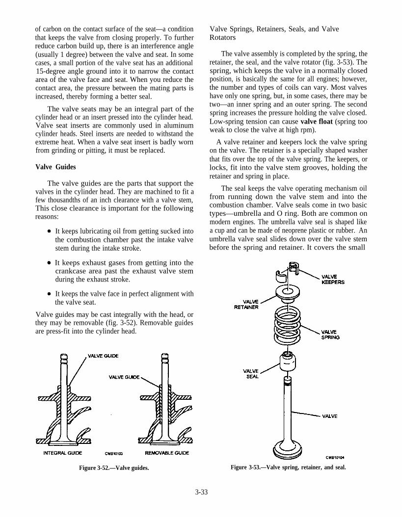
of carbon on the contact surface of the seat—a conditionthat keeps the valve from closing properly. To furtherreduce carbon build up, there is an interference angle(usually 1 degree) between the valve and seat. In somecases, a small portion of the valve seat has an additional15-degree angle ground into it to narrow the contactarea of the valve face and seat. When you reduce thecontact area, the pressure between the mating parts isincreased, thereby forming a better seal.
The valve seats may be an integral part of thecylinder head or an insert pressed into the cylinder head.Valve seat inserts are commonly used in aluminumcylinder heads. Steel inserts are needed to withstand theextreme heat. When a valve seat insert is badly wornfrom grinding or pitting, it must be replaced.
Valve Guides
The valve guides are the parts that support thevalves in the cylinder head. They are machined to fit afew thousandths of an inch clearance with a valve stem,This close clearance is important for the followingreasons:
It keeps lubricating oil from getting sucked intothe combustion chamber past the intake valvestem during the intake stroke.
It keeps exhaust gases from getting into thecrankcase area past the exhaust valve stemduring the exhaust stroke.
It keeps the valve face in perfect alignment withthe valve seat.
Valve guides may be cast integrally with the head, orthey may be removable (fig. 3-52). Removable guidesare press-fit into the cylinder head.
Figure 3-52.—Valve guides.
Valve Springs, Retainers, Seals, and ValveRotators
The valve assembly is completed by the spring, theretainer, the seal, and the valve rotator (fig. 3-53). Thespring, which keeps the valve in a normally closedposition, is basically the same for all engines; however,the number and types of coils can vary. Most valveshave only one spring, but, in some cases, there may betwo—an inner spring and an outer spring. The secondspring increases the pressure holding the valve closed.Low-spring tension can cause valve float (spring tooweak to close the valve at high rpm).
A valve retainer and keepers lock the valve springon the valve. The retainer is a specially shaped washerthat fits over the top of the valve spring. The keepers, orlocks, fit into the valve stem grooves, holding theretainer and spring in place.
The seal keeps the valve operating mechanism oilfrom running down the valve stem and into thecombustion chamber. Valve seals come in two basictypes—umbrella and O ring. Both are common onmodern engines. The umbrella valve seal is shaped likea cup and can be made of neoprene plastic or rubber. Anumbrella valve seal slides down over the valve stembefore the spring and retainer. It covers the small
Figure 3-53.—Valve spring, retainer, and seal.
3-33
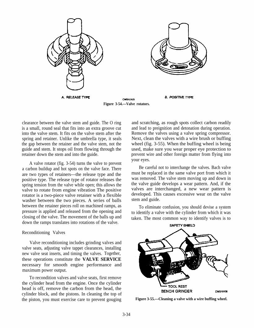
Figure 3-54.—Valve rotators.
clearance between the valve stem and guide. The O ringis a small, round seal that fits into an extra groove cutinto the valve stem. It fits on the valve stem after thespring and retainer. Unlike the umbrella type, it sealsthe gap between the retainer and the valve stem, not theguide and stem. It stops oil from flowing through theretainer down the stem and into the guide.
A valve rotator (fig. 3-54) turns the valve to preventa carbon buildup and hot spots on the valve face. Thereare two types of retainers—the release type and thepositive type. The release type of rotator releases thespring tension from the valve while open; this allows thevalve to rotate from engine vibration The positiverotator is a two-piece valve retainer with a flexiblewasher between the two pieces. A series of ballsbetween the retainer pieces roll on machined ramps, aspressure is applied and released from the opening andclosing of the valve. The movement of the balls up anddown the ramps translates into rotations of the valve.
Reconditioning Valves
Valve reconditioning includes grinding valves andvalve seats, adjusting valve tappet clearances, installingnew valve seat inserts, and timing the valves. Together,these operations constitute the VALVE SERVICEnecessary for smooth engine performance andmaximum power output.
To recondition valves and valve seats, first removethe cylinder head from the engine. Once the cylinderhead is off, remove the carbon from the head, thecylinder block, and the pistons. In cleaning the top ofthe piston, you must exercise care to prevent gouging
and scratching, as rough spots collect carbon readilyand lead to preignition and detonation during operation.Remove the valves using a valve spring compressor.Next, clean the valves with a wire brush or buffingwheel (fig. 3-55). When the buffing wheel is beingused, make sure you wear proper eye protection toprevent wire and other foreign matter from flying intoyour eyes.
Be careful not to interchange the valves. Bach valvemust be replaced in the same valve port from which itwas removed. The valve stem moving up and down inthe valve guide develops a wear pattern. And, if thevalves are interchanged, a new wear pattern isdeveloped. This causes excessive wear on the valvestem and guide.
To eliminate confusion, you should devise a systemto identify a valve with the cylinder from which it wastaken. The most common way to identify valves is to
Figure 3-55.—Cleaning a valve with a wire buffing wheel.
3-34

place them on a piece of board with holes drilled andnumbered to correspond with the cylinder each valvecame from.
The next step is to resurface the valve face. This isdone by using a valve grinding or refacing machine.VALVE GRINDING is done by machining a fresh,smooth surface on the face and stem tips. Valve facessuffer from burning, pitting, and wear caused byopening and closing millions of times during the servicelife of the engine. Valve stem tips wear because offriction from the rocker arms.
Although there are some variations in design, mostvalve grinding machines (fig. 3-56) are basically thesame. They use a grinding stone and a precision chuckto remove a thin layer of metal from the valve and stemtip. The following steps are used in preparing to reface avalve:
DRESS THE STONE by using a diamondcutter to true stone surface (fig. 3-57). Do thisbefore grinding the valves. A diamond-tippedcutting attachment is provided with the machinefor truing the stone. Follow the equipmentmanufacturer’s instructions for that specificpiece equipment.
CAUTION
Be careful when using a diamond tool to dressa stone. Wear eye protection and feed thediamond into the stone SLOWLY. If fed toofast, tool or stone breakage may result.
WARNING
The chuck must NOT clamp onto anunmachined surface or runout will occur.
SET THE CHUCK ANGLE by rotating thevalve grinding machine chuck assembly. An
interference angle (normally 1 degreedifference in valve face angle and valve seatangle) is set on the machine. If the valve seat is
Figure 3-57.—Stone dresser.
45 degrees, the chuck is set to 44 degrees. Thisallows for reduced break-in and sealing time.
CHUCK THE VALVE in the valve grindingmachine by inserting the valve stem into thechuck Make sure the stem is inserted so thechuck grasps the machine surface nearest thevalve head.
Before grinding, inspect each valve face forburning and each stem for wear. Replace valves that arebadly worn or burned. Grind a new valve along with theold, used valves.
WARNING
Wear a face shield when grinding valves. Thestone could shatter, throwing debris into yourface.
To grind the valve face, turn on the machine andcooling fluid SLOWLY feed the valve into the stone.While feeding, slowly move the valve back and forth infront of the stone. Use the full face of the stone but doNOT let the valve face move out of contact with thestone while cutting. Grind the valve only long enoughto clean up its face. When the full valve face looks shinywith no darken pits, shut the machine off and inspect the
Figure 3-56.—Valve-refacing machine. face.
3-35
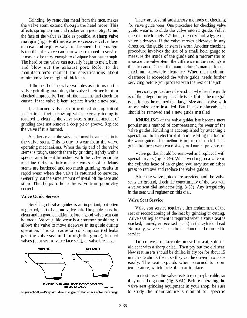
Grinding, by removing metal from the face, makesthe valve stem extend through the head more. Thisaffects spring tension and rocker-arm geometry. Grindthe face of the valve as little as possible. A sharp valvemargin (fig. 3-58) indicates excessive valve faceremoval and requires valve replacement. If the marginis too thin, the valve can burn when returned to service.It may not be thick enough to dissipate heat fast enough.The head of the valve can actually begin to melt, burn,and blow out the exhaust port. Refer to themanufacturer’s manual for specifications aboutminimum valve margin of thickness.
If the head of the valve wobbles as it turns on thevalve grinding machine, the valve is either bent orchucked improperly. Turn off the machine and check forcauses. If the valve is bent, replace it with a new one.
If a burned valve is not noticed during initialinspection, it will show up when excess grinding isrequired to clean up the valve face. A normal amount ofgrinding does not remove a deep pit or groove. Replacethe valve if it is burned.
There are several satisfactory methods of checkingfor valve guide wear. One procedure for checking valveguide wear is to slide the valve into its guide. Full itopen approximately 1/2 inch, then try and wiggle thevalve sideways. If the valve moves sideways in anydirection, the guide or stem is worn Another checkingprocedure involves the use of a small hole gauge tomeasure the inside of the guide and a micrometer tomeasure the valve stem; the difference in the readings isthe clearance. Check the manufacturer's manual for themaximum allowable clearance. When the maximumclearance is exceeded the valve guide needs furtherservicing before you proceed with the rest of the job.
Servicing procedures depend on whether the guideis of the integral or replaceable type. If it is the integraltype, it must be reamed to a larger size and a valve withan oversize stem installed. But if it is replaceable, itshould be removed and a new guide installed
Another area on the valve that must be attended to isthe valve stem. This is due to wear from the valveoperating mechanisms. When the tip end of the valvestems is rough, smooth them by grinding lightly with aspecial attachment furnished with the valve grindingmachine. Grind as little off the stem as possible. Manystems are hardened and too much grinding results inrapid wear when the valve is returned to service.Generally, cut the same amount of metal off the face andstem. This helps to keep the valve train geometrycorrect.
KNURLING of the valve guides has become morepopular as a method of compensating for wear of thevalve guides. Knurling is accomplished by attaching aspecial tool to an electric drill and inserting the tool inthe worn guide. This method is not recommended if theguide has been worn excessively or knurled previously.
Valve guides should be removed and replaced withspecial drivers (fig. 3-59). When working on a valve inthe cylinder head of an engine, you may use an arborpress to remove and replace the valve guides.
Valve Guide Service
After the valve guides are serviced and the valveseats are ground, check the concentricity of the two witha valve seat dial indicator (fig. 3-60). Any irregularityin the seat will register on this dial.
Servicing of valve guides is an important, but oftenneglected, part of a good valve job. The guide must beclean and in good condition before a good valve seat canbe made. Valve guide wear is a common problem; itallows the valve to move sideways in its guide duringoperation. This can cause oil consumption (oil leakspast the valve seal and through the guide), burnedvalves (poor seat to valve face seal), or valve breakage.
Valve Seat Service
3-36
Figure 3-58.—Proper valve margin of thickness after refacing.
Valve seat service requires either replacement of theseat or reconditioning of the seat by grinding or cutting.Valve seat replacement is required when a valve seat iscracked, burned, or recessed (sunk) in the cylinder headNormally, valve seats can be machined and returned toservice.
To remove a replaceable pressed-in seat, split theold seat with a sharp chisel. Then pry out the old seat.New seat inserts should be chilled in dry ice for about 15minutes to shrink them, so they can be driven into placeeasily. The seat expands when returned to roomtemperature, which locks the seat in place.
In most cases, the valve seats are not replaceable, sothey must be ground (fig. 3-61). Before operating thevalve seat grinding equipment in your shop, be sureto study the manufacturer’s manual for specific
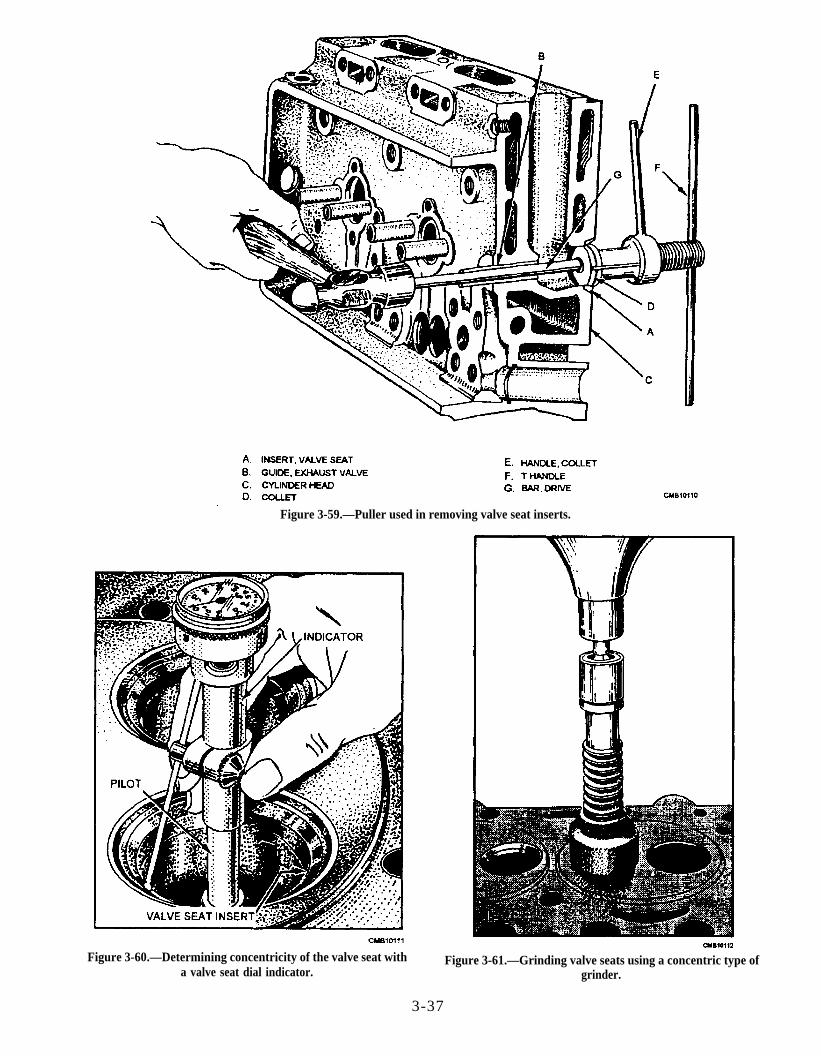
Figure 3-59.—Puller used in removing valve seat inserts.
Figure 3-60.—Determining concentricity of the valve seat with Figure 3-61.—Grinding valve seats using a concentric type ofa valve seat dial indicator. grinder.
3-37
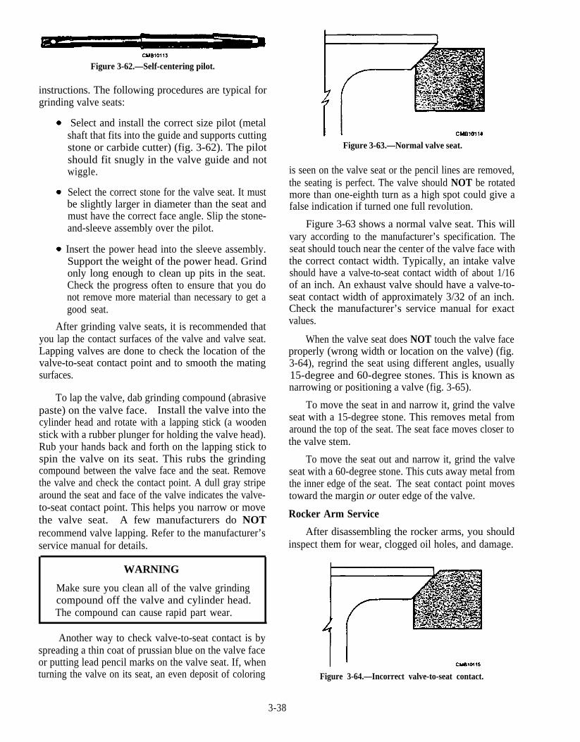
Figure 3-62.—Self-centering pilot.
instructions. The following procedures are typical forgrinding valve seats:
Select and install the correct size pilot (metalshaft that fits into the guide and supports cuttingstone or carbide cutter) (fig. 3-62). The pilotshould fit snugly in the valve guide and notwiggle.
Select the correct stone for the valve seat. It mustbe slightly larger in diameter than the seat andmust have the correct face angle. Slip the stone-and-sleeve assembly over the pilot.
Insert the power head into the sleeve assembly.Support the weight of the power head. Grindonly long enough to clean up pits in the seat.Check the progress often to ensure that you donot remove more material than necessary to get agood seat.
After grinding valve seats, it is recommended thatyou lap the contact surfaces of the valve and valve seat.Lapping valves are done to check the location of thevalve-to-seat contact point and to smooth the matingsurfaces.
To lap the valve, dab grinding compound (abrasivepaste) on the valve face. Install the valve into thecylinder head and rotate with a lapping stick (a woodenstick with a rubber plunger for holding the valve head).Rub your hands back and forth on the lapping stick tospin the valve on its seat. This rubs the grindingcompound between the valve face and the seat. Removethe valve and check the contact point. A dull gray stripearound the seat and face of the valve indicates the valve-to-seat contact point. This helps you narrow or movethe valve seat. A few manufacturers do NOTrecommend valve lapping. Refer to the manufacturer’sservice manual for details.
WARNING
Make sure you clean all of the valve grindingcompound off the valve and cylinder head.The compound can cause rapid part wear.
Another way to check valve-to-seat contact is byspreading a thin coat of prussian blue on the valve faceor putting lead pencil marks on the valve seat. If, whenturning the valve on its seat, an even deposit of coloring
Figure 3-63.—Normal valve seat.
is seen on the valve seat or the pencil lines are removed,the seating is perfect. The valve should NOT be rotatedmore than one-eighth turn as a high spot could give afalse indication if turned one full revolution.
Figure 3-63 shows a normal valve seat. This willvary according to the manufacturer’s specification. Theseat should touch near the center of the valve face withthe correct contact width. Typically, an intake valveshould have a valve-to-seat contact width of about 1/16of an inch. An exhaust valve should have a valve-to-seat contact width of approximately 3/32 of an inch.Check the manufacturer’s service manual for exactvalues.
When the valve seat does NOT touch the valve faceproperly (wrong width or location on the valve) (fig.3-64), regrind the seat using different angles, usually15-degree and 60-degree stones. This is known asnarrowing or positioning a valve (fig. 3-65).
To move the seat in and narrow it, grind the valveseat with a 15-degree stone. This removes metal fromaround the top of the seat. The seat face moves closer tothe valve stem.
To move the seat out and narrow it, grind the valveseat with a 60-degree stone. This cuts away metal fromthe inner edge of the seat. The seat contact point movestoward the margin or outer edge of the valve.
Rocker Arm Service
After disassembling the rocker arms, you shouldinspect them for wear, clogged oil holes, and damage.
Figure 3-64.—Incorrect valve-to-seat contact.
3-38
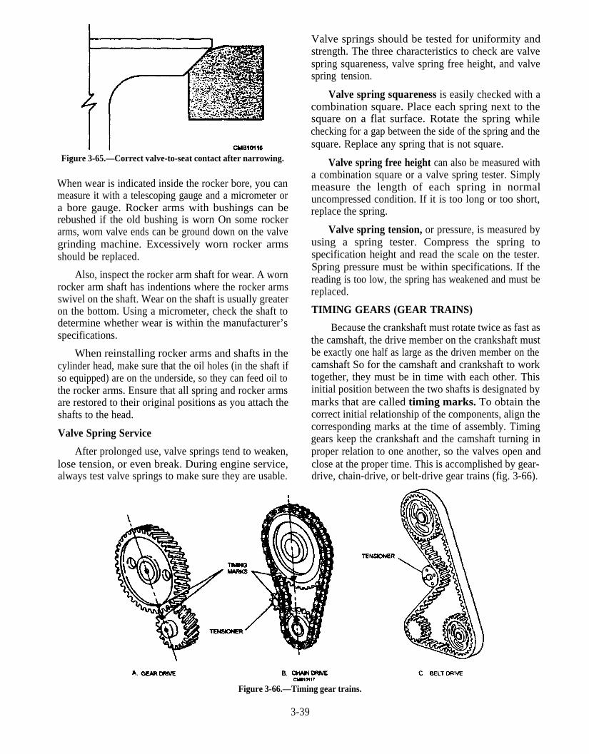
Figure 3-65.—Correct valve-to-seat contact after narrowing.
When wear is indicated inside the rocker bore, you canmeasure it with a telescoping gauge and a micrometer ora bore gauge. Rocker arms with bushings can berebushed if the old bushing is worn On some rockerarms, worn valve ends can be ground down on the valvegrinding machine. Excessively worn rocker armsshould be replaced.
Also, inspect the rocker arm shaft for wear. A wornrocker arm shaft has indentions where the rocker armsswivel on the shaft. Wear on the shaft is usually greateron the bottom. Using a micrometer, check the shaft todetermine whether wear is within the manufacturer’sspecifications.
When reinstalling rocker arms and shafts in thecylinder head, make sure that the oil holes (in the shaft ifso equipped) are on the underside, so they can feed oil tothe rocker arms. Ensure that all spring and rocker armsare restored to their original positions as you attach theshafts to the head.
Valve Spring Service
After prolonged use, valve springs tend to weaken,lose tension, or even break. During engine service,always test valve springs to make sure they are usable.
Valve springs should be tested for uniformity andstrength. The three characteristics to check are valvespring squareness, valve spring free height, and valvespring tension.
Valve spring squareness is easily checked with acombination square. Place each spring next to thesquare on a flat surface. Rotate the spring whilechecking for a gap between the side of the spring and thesquare. Replace any spring that is not square.
Valve spring free height can also be measured witha combination square or a valve spring tester. Simplymeasure the length of each spring in normaluncompressed condition. If it is too long or too short,replace the spring.
Valve spring tension, or pressure, is measured byusing a spring tester. Compress the spring tospecification height and read the scale on the tester.Spring pressure must be within specifications. If thereading is too low, the spring has weakened and must bereplaced.
TIMING GEARS (GEAR TRAINS)
Because the crankshaft must rotate twice as fast asthe camshaft, the drive member on the crankshaft mustbe exactly one half as large as the driven member on thecamshaft So for the camshaft and crankshaft to worktogether, they must be in time with each other. Thisinitial position between the two shafts is designated bymarks that are called timing marks. To obtain thecorrect initial relationship of the components, align thecorresponding marks at the time of assembly. Timinggears keep the crankshaft and the camshaft turning inproper relation to one another, so the valves open andclose at the proper time. This is accomplished by gear-drive, chain-drive, or belt-drive gear trains (fig. 3-66).
Figure 3-66.—Timing gear trains.
3-39
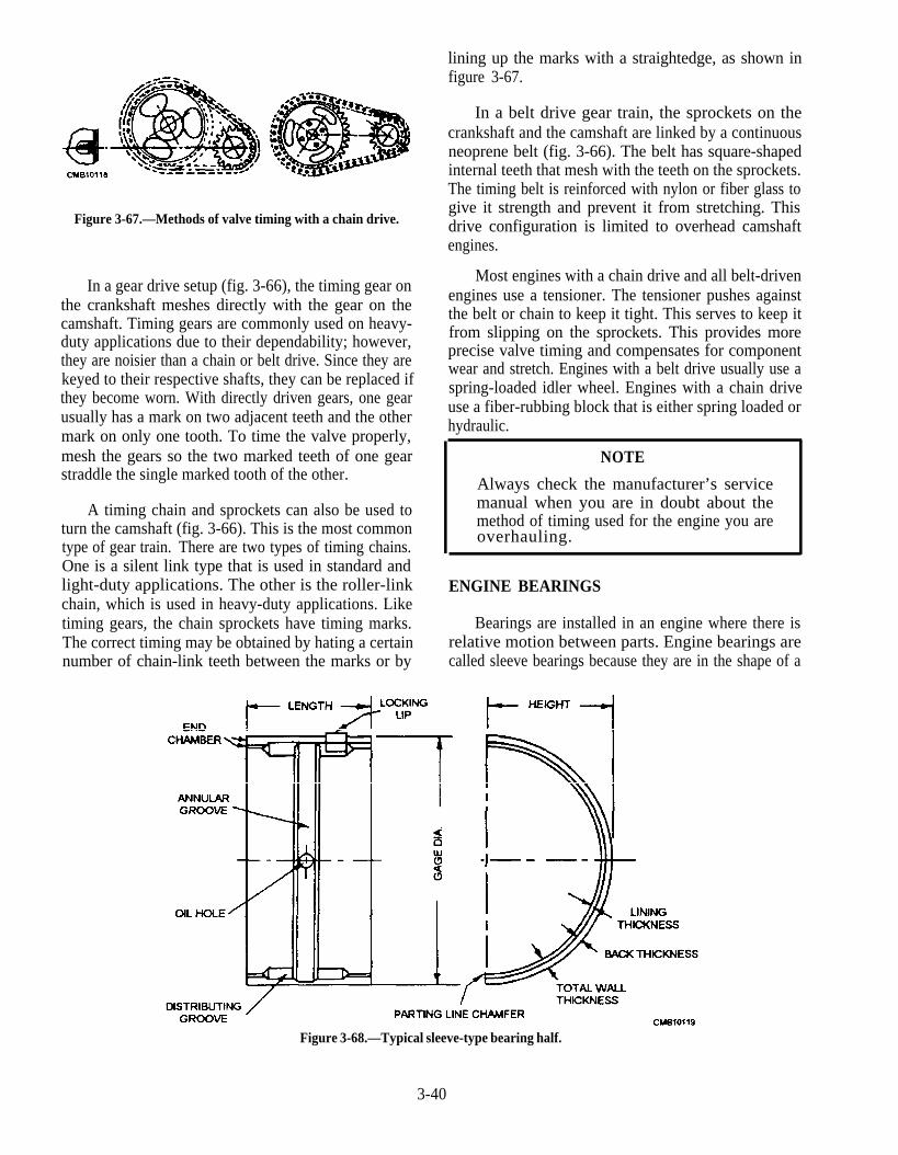
Figure 3-67.—Methods of valve timing with a chain drive.
In a gear drive setup (fig. 3-66), the timing gear onthe crankshaft meshes directly with the gear on thecamshaft. Timing gears are commonly used on heavy-duty applications due to their dependability; however,they are noisier than a chain or belt drive. Since they arekeyed to their respective shafts, they can be replaced ifthey become worn. With directly driven gears, one gearusually has a mark on two adjacent teeth and the othermark on only one tooth. To time the valve properly,mesh the gears so the two marked teeth of one gearstraddle the single marked tooth of the other.
A timing chain and sprockets can also be used toturn the camshaft (fig. 3-66). This is the most commontype of gear train. There are two types of timing chains.One is a silent link type that is used in standard andlight-duty applications. The other is the roller-linkchain, which is used in heavy-duty applications. Liketiming gears, the chain sprockets have timing marks.The correct timing may be obtained by hating a certainnumber of chain-link teeth between the marks or by
lining up the marks with a straightedge, as shown infigure 3-67.
In a belt drive gear train, the sprockets on thecrankshaft and the camshaft are linked by a continuousneoprene belt (fig. 3-66). The belt has square-shapedinternal teeth that mesh with the teeth on the sprockets.The timing belt is reinforced with nylon or fiber glass togive it strength and prevent it from stretching. Thisdrive configuration is limited to overhead camshaftengines.
Most engines with a chain drive and all belt-drivenengines use a tensioner. The tensioner pushes againstthe belt or chain to keep it tight. This serves to keep itfrom slipping on the sprockets. This provides moreprecise valve timing and compensates for componentwear and stretch. Engines with a belt drive usually use aspring-loaded idler wheel. Engines with a chain driveuse a fiber-rubbing block that is either spring loaded orhydraulic.
NOTE
Always check the manufacturer’s servicemanual when you are in doubt about themethod of timing used for the engine you areoverhauling.
ENGINE BEARINGS
Bearings are installed in an engine where there isrelative motion between parts. Engine bearings arecalled sleeve bearings because they are in the shape of a
Figure 3-68.—Typical sleeve-type bearing half.
3-40
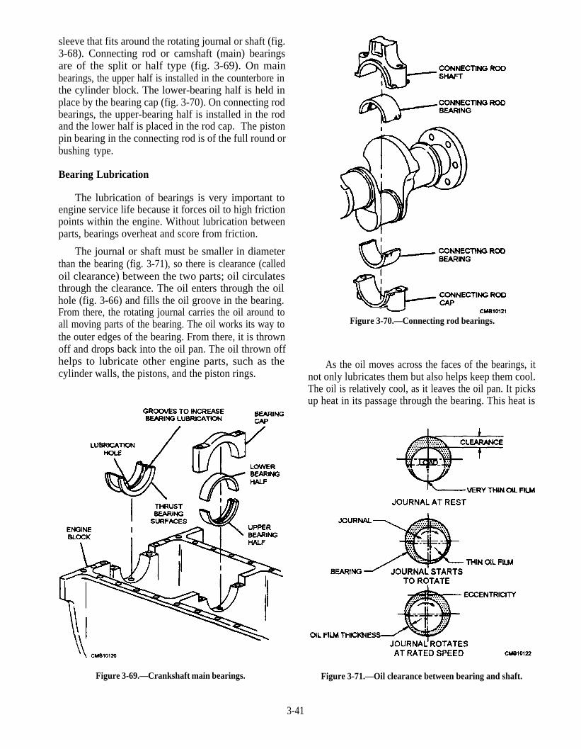
sleeve that fits around the rotating journal or shaft (fig.3-68). Connecting rod or camshaft (main) bearingsare of the split or half type (fig. 3-69). On mainbearings, the upper half is installed in the counterbore inthe cylinder block. The lower-bearing half is held inplace by the bearing cap (fig. 3-70). On connecting rodbearings, the upper-bearing half is installed in the rodand the lower half is placed in the rod cap. The pistonpin bearing in the connecting rod is of the full round orbushing type.
Bearing Lubrication
The lubrication of bearings is very important toengine service life because it forces oil to high frictionpoints within the engine. Without lubrication betweenparts, bearings overheat and score from friction.
The journal or shaft must be smaller in diameterthan the bearing (fig. 3-71), so there is clearance (calledoil clearance) between the two parts; oil circulatesthrough the clearance. The oil enters through the oilhole (fig. 3-66) and fills the oil groove in the bearing.From there, the rotating journal carries the oil around toall moving parts of the bearing. The oil works its way tothe outer edges of the bearing. From there, it is thrownoff and drops back into the oil pan. The oil thrown offhelps to lubricate other engine parts, such as thecylinder walls, the pistons, and the piston rings.
Figure 3-69.—Crankshaft main bearings.
Figure 3-70.—Connecting rod bearings.
As the oil moves across the faces of the bearings, itnot only lubricates them but also helps keep them cool.The oil is relatively cool, as it leaves the oil pan. It picksup heat in its passage through the bearing. This heat is
Figure 3-71.—Oil clearance between bearing and shaft.
3-41
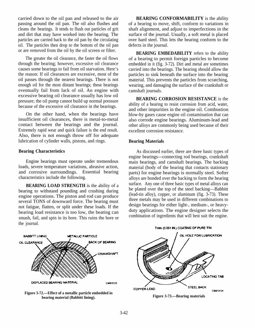
carried down to the oil pan and released to the airpassing around the oil pan. The oil also flushes andcleans the bearings. It tends to flush out particles of gritand dirt that may have worked into the bearing. Theparticles are carried back to the oil pan by the circulatingoil. The particles then drop to the bottom of the oil panor are removed from the oil by the oil screen or filter.
The greater the oil clearance, the faster the oil flowsthrough the bearing; however, excessive oil clearancecauses some bearings to fail from oil starvation. Here’sthe reason: If oil clearances are excessive, most of theoil passes through the nearest bearings. There is notenough oil for the most distant bearings; these bearingseventually fail from lack of oil. An engine withexcessive bearing oil clearance usually has low oilpressure; the oil pump cannot build up normal pressurebecause of the excessive oil clearance in the bearings.
On the other hand, when the bearings haveinsufficient oil clearances, there is metal-to-metalcontact between the bearings and the journal.Extremely rapid wear and quick failure is the end result.Also, there is not enough throw off for adequatelubrication of cylinder walls, pistons, and rings.
Bearing Characteristics
Engine bearings must operate under tremendousloads, severe temperature variations, abrasive action,and corrosive surroundings. Essential bearingcharacteristics include the following.
BEARING LOAD STRENGTH is the ability of abearing to withstand pounding and crushing duringengine operations. The piston and rod can produceseveral TONS of downward force. The bearing mustnot fatigue, flatten, or split under these loads. If thebearing load resistance is too low, the beating cansmash, fail, and spin in its bore. This ruins the bore orthe journal.
BEARING CONFORMABILITY is the abilityof a bearing to move, shift, conform to variations inshaft alignment, and adjust to imperfections in thesurface of the journal. Usually, a soft metal is placedover hard steel. This lets the bearing conform to thedefects in the journal.
BEARING EMBEDABILITY refers to the abilityof a bearing to permit foreign particles to becomeembedded in it (fig. 3-72). Dirt and metal are sometimescarried into the bearings. The bearing should allow theparticles to sink beneath the surface into the bearingmaterial. This prevents the particles from scratching,wearing, and damaging the surface of the crankshaft orcamshaft journals.
BEARING CORROSION RESISTANCE is theability of a bearing to resist corrosion from acid, water,and other impurities in the engine oil. Combustionblow-by gases cause engine oil contamination that canalso corrode engine bearings. Aluminum-lead andother alloys are commonly being used because of theirexcellent corrosion resistance.
Bearing Materials
As discussed earlier, there are three basic types ofengine bearings—connecting rod bearings, crankshaftmain bearings, and camshaft bearings. The backingmaterial (body of the bearing that contacts stationaryparts) for engine bearings is normally steel. Softeralloys are bonded over the backing to form the bearingsurface. Any one of three basic types of metal alloys canbe plated over the top of the steel backing—Babbitt(lead-tin alloy), copper, or aluminum (fig. 3-73). Thesethree metals may be used in different combinations todesign bearings for either light-, medium-, or heavy-duty applications. The engine designer selects thecombination of ingredients that will best suit the engine.
Figure 3-72.—Effect of a metallic particle embedded inbearing material (Babbitt lining). Figure 3-73.—Bearing materials
3-42
Q1. What material is commonly used to provide awearing surface in a liquid-cooled engine for thepistons to ride against?
Q2. What are the two types of cylinder sleeves?
Q3. What are the two types of core hole plugs used inan internal combustion engine?
Q4. What is the basic foundation of all air-cooledengines ?
Q5. A properly made exhaust manifold results inwhat type of action to help an engine get rid ofexhaust gases?
Q6. In an exhaust-heated intake manifold, gasesdiverted to the manifold are controlled by whatvalve?
Q7. What two basic types of oil seals are currentlybeing used on engines?
Q8. What ate the structural components of a piston?
Q9. What are the three types of piston pinconfigurations?
Q1O. What three functions do piston rings serve?
Q11. What part is the backbone of an internalcombustion engine?
Q12. The valve actuating mechanism is made up ofwhat engine parts?
Q13. What are the three basic shapes of a poppet-typevalve ?
Q14. What type of valve is preferred in a vehicle usingunleaded fuel?
Q15. What are the two basic types of valve seals?
Q16. What three characteristics of a valve springshould you check?
ENGINE ADJUSTMENT ANDTESTING
LEARNING OBJECTIVE: Describe Thetechniques used in adjusting engine valves.Recognize basic engine testing procedures andrequired tools.
Proper and uniform valve adjustments are requiredfor a smooth running engine. Unless the clearancebetween the valve stems and rocker arms or valve liftersis adjusted according to the manufacturer’s
specifications, a valve does not open and close at theproper time, and engine performance is affected.
In most shops, the Navy provides accurate anddependable testing equipment. But having the testingequipment in the shop is NOT enough. The supervisorand crew must know how to use this equipment properlysince it provides the quickest and surest means ofdetermining what is wrong and where the fault lies.
VALVE ADJUSTMENT
Valve adjustment, also called tappet clearanceadjustment or rocker adjustment, is critical to theperformance and service life of an engine. If the valvetrain is too loose (too much clearance), it can causevalve train noise (tapping or clattering noise from therocker striking the valve stems). This can increase partwear and cause part breakage. Valves that are adjustedtoo tight (inadequate clearance) may be held open ormay not close completely. This can allow combustionheat to blow over and burn the valve.
When reassembling an engine after reconditioningthe valves, make sure the adjusting screws are backedoff before rotating the engine. A valve that is too tightcould strike the piston and damage either the piston orthe valve, or both. Adjust the valve according tomanufacturer’s specifications, following therecommended procedure.
On any engine, after valve adjustments have beenmade, be sure that the adjustment locks are tight and thatthe valve mechanism covers and gaskets are in placeand fastened securely to prevent oil leaks.
Overhead Valves
Most overhead valves are adjusted "HOT"; that is,valve clearance recommendations are given for anengine at operating temperature. Before valveadjustments can be made properly, the engine must berun and brought up to normal operating temperature.
To adjust a valve, remove the valve cover andmeasure the clearance between the valve stem and therocker arm. Loosen the locknut and turn the adjusting
3-43
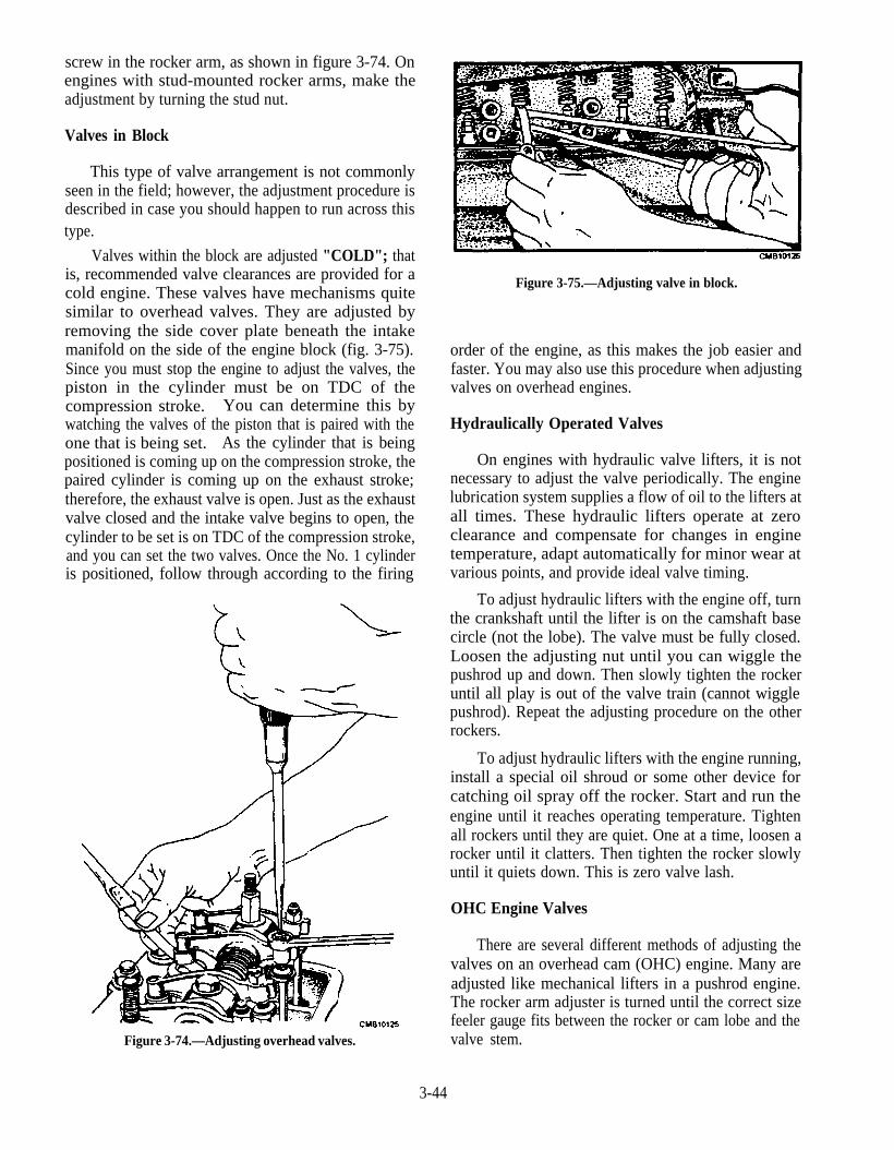
screw in the rocker arm, as shown in figure 3-74. Onengines with stud-mounted rocker arms, make theadjustment by turning the stud nut.
Valves in Block
This type of valve arrangement is not commonlyseen in the field; however, the adjustment procedure isdescribed in case you should happen to run across thistype.
Valves within the block are adjusted "COLD"; thatis, recommended valve clearances are provided for acold engine. These valves have mechanisms quitesimilar to overhead valves. They are adjusted byremoving the side cover plate beneath the intakemanifold on the side of the engine block (fig. 3-75).Since you must stop the engine to adjust the valves, thepiston in the cylinder must be on TDC of thecompression stroke. You can determine this bywatching the valves of the piston that is paired with theone that is being set. As the cylinder that is beingpositioned is coming up on the compression stroke, thepaired cylinder is coming up on the exhaust stroke;therefore, the exhaust valve is open. Just as the exhaustvalve closed and the intake valve begins to open, thecylinder to be set is on TDC of the compression stroke,and you can set the two valves. Once the No. 1 cylinderis positioned, follow through according to the firing
Figure 3-74.—Adjusting overhead valves.
Figure 3-75.—Adjusting valve in block.
order of the engine, as this makes the job easier andfaster. You may also use this procedure when adjustingvalves on overhead engines.
Hydraulically Operated Valves
On engines with hydraulic valve lifters, it is notnecessary to adjust the valve periodically. The enginelubrication system supplies a flow of oil to the lifters atall times. These hydraulic lifters operate at zeroclearance and compensate for changes in enginetemperature, adapt automatically for minor wear atvarious points, and provide ideal valve timing.
To adjust hydraulic lifters with the engine off, turnthe crankshaft until the lifter is on the camshaft basecircle (not the lobe). The valve must be fully closed.Loosen the adjusting nut until you can wiggle thepushrod up and down. Then slowly tighten the rockeruntil all play is out of the valve train (cannot wigglepushrod). Repeat the adjusting procedure on the otherrockers.
To adjust hydraulic lifters with the engine running,install a special oil shroud or some other device forcatching oil spray off the rocker. Start and run theengine until it reaches operating temperature. Tightenall rockers until they are quiet. One at a time, loosen arocker until it clatters. Then tighten the rocker slowlyuntil it quiets down. This is zero valve lash.
OHC Engine Valves
There are several different methods of adjusting thevalves on an overhead cam (OHC) engine. Many areadjusted like mechanical lifters in a pushrod engine.The rocker arm adjuster is turned until the correct sizefeeler gauge fits between the rocker or cam lobe and thevalve stem.
3-44
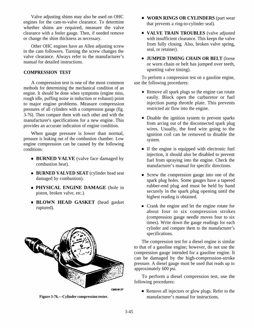
Valve adjusting shims may also be used on OHCengines for the cam-to-valve clearance. To determinewhether shims are required, measure the valveclearance with a feeler gauge. Then, if needed removeor change the shim thickness as necessary.
Other OHC engines have an Allen adjusting screwin the cam followers. Turning the screw changes thevalve clearance. Always refer to the manufacturer’smanual for detailed instructions.
COMPRESSION TEST
A compression test is one of the most commonmethods for determining the mechanical condition of anengine. It should be done when symptoms (engine miss,rough idle, puffing noise in induction or exhaust) pointto major engine problems. Measure compressionpressures of all cylinders with a compression gauge (fig.3-76). Then compare them with each other and with themanufacturer's specifications for a new engine. Thisprovides an accurate indication of engine condition.
When gauge pressure is lower than normal,pressure is leaking out of the combustion chamber. Lowengine compression can be caused by the followingconditions:
BLOWN HEAD GASKET (head gasketruptured).
PHYSICAL ENGINE DAMAGE (hole inpiston, broken valve, etc.).
BURNED VALVED SEAT (cylinder head seatdamaged by combustion).
BURNED VALVE (valve face damaged bycombustion heat).
Figure 3-76.—Cylinder compression tester.
WORN RINGS OR CYLINDERS (part wearthat prevents a ring-to-cylinder seal).
VALVE TRAIN TROUBLES (valve adjustedwith insufficient clearance. This keeps the valvefrom fully closing. Also, broken valve spring,seal, or retainer).
JUMPED TIMING CHAIN OR BELT (looseor worn chain or belt has jumped over teeth,upsetting valve timing).
To perform a compression test on a gasoline engine,use the following procedures:
Remove all spark plugs so the engine can rotateeasily. Block open the carburetor or fuelinjection pump throttle plate. This preventsrestricted air flow into the engine.
Disable the ignition system to prevent sparksfrom arcing out of the disconnected spark plugwires. Usually, the feed wire going to theignition coil can be removed to disable thesystem.
If the engine is equipped with electronic fuelinjection, it should also be disabled to preventfuel from spraying into the engine. Check themanufacturer’s manual for specific directions.
Screw the compression gauge into one of thespark plug holes. Some gauges have a taperedrubber-end plug and must be held by handsecurely in the spark plug opening until thehighest reading is obtained.
Crank the engine and let the engine rotate forabout four to six compression strokes(compression gauge needle moves four to sixtimes). Write down the gauge readings for eachcylinder and compare them to the manufacturer’sspecifications.
The compression test for a diesel engine is similarto that of a gasoline engine; however, do not use thecompression gauge intended for a gasoline engine. Itcan be damaged by the high-compression-strokepressure. A diesel gauge must be used that reads up toapproximately 600 psi.
To perform a diesel compression test, use thefollowing procedures:
Remove all injectors or glow plugs. Refer to themanufacturer’s manual for instructions.
3-45
Install the compression gauge in therecommended opening. A heat shield must beused to seal the gauge when it is installed in placeof the injector.
Disconnect the fuel shut-off solenoid to disablethe fuel injection pump.
Crank the engine and note the highest reading onthe gauge.
A wet compression test should be used whencylinder pressure reads below the manufacturer'sspecifications. It helps you to determine what engineparts are causing the problem. Pour approximately 1tablespoon of 30-weight motor oil into the cylinderthrough the spark plug or injector opening, then retestthe compression pressure.
If the compression reading GOES UP with oil in thecylinder, the piston rings and cylinders may be worn andleaking pressure. The oil will temporarily coat and sealbad compression rings to increase pressure; however, ifthe compression reading STAYS ABOUT THE SAME,then engine valves or head gaskets may be leaking. Theengine oil seals the rings, but does NOT seal a burnedvalve or a blown head gasket. In this way, a wetcompression test helps diagnose low-compressionproblems.
Do NOT put too much oil into the cylinder during awet compression test or a false reading may result. Withexcessive oil in the cylinder, compression readings goup even if the compression rings and cylinders are ingood condition.
NOTE
Some manufacturers warn against performinga wet compression test on diesel engines. If toomuch oil is squirted into the cylinder, hydrauliclock and part damage may result, because oildoes NOT compress in the small cylindervolume.
Compression readings for a gasoline engine should
3-46
run around 125 to 175 psi. The compression should notvary over 15 to 20 psi from the highest to the lowestcylinder. Readings must be within 10 to 15 percent ofeach other. Diesel engine compression readingsaverage approximately 275 to 400 psi, depending on thedesign and compression ratio. Compression levelsmust not vary more than about 10 to 15 percent (30 to 50psi). Look for cylinder variation during an enginecompression check. If some cylinders have normal
pressure readings and one or two have low readings,engine performance is reduced. If two adjacentcylinders read low, it might point to a blown head gasketbetween the two cylinders. If the compression pressureof a cylinder is low for the first few piston strokes andthen increases to near normal, a sticking valve isindicated. Indications of valve troubles by compressiontest may be confirmed by taking vacuum gaugereadings.
VACUUM GAUGE TEST
When an engine has an abnormal compressionreading, it is likely that the cylinder head must beremoved to repair the trouble. Nevertheless, themechanics should test the vacuum of the engine with agauge. The vacuum gauge provides a means of testingintake manifold vacuum, cranking vacuum, fuel pumpvacuum, and booster pump vacuum. The vacuumgauge does NOT replace other test equipment, butrather supplements it and diagnoses engine troublemore conclusively.
Vacuum gauge readings are taken with the enginerunning and must be accurate to be of any value;therefore, the connection between the gauge and theintake manifold must be leakproof. Also, before theconnection is made, see that the openings to the gaugeand the intake manifold are free of dirt or otherrestrictions.
When a test is made at an elevation of 1,000 feet orless, an engine in good condition, idling at a speed ofabout 550 rpm, should give a steady reading from 17 to22 inches on the vacuum gauge. The average readingwill drop approximately 1 inch of vacuum per 1,000 feetat altitudes of 1,000 feet or higher above sea level.
When the throttle is opened and closed suddenly,the vacuum reading should first drop about 2 incheswith the throttle open, and then come back to a high ofabout 24 inches before settling back to a steady readingas the engine idles, as shown in figure 3-77. This isnormal for an engine in good operating condition.
If the gauge reading drops to about 15 inches andremains there, it would indicate compression leaksbetween the cylinder walls and the piston rings or powerloss caused by incorrect ignition timing. A vacuumgauge pointer indicating a steady 10 inches, forexample, usually means that valve timing of the engineis incorrect. Below-normal readings that change slowlybetween two limits, such as 14 and 16 inches, couldindicate a number of problems. Among them areimproper carburetor idling adjustment, maladjusted or

Figure 3-77.—Approximate vacuum gauge readings on anormal operating engine.
burned breaker points, and spark plugs with theelectrodes set too closely.
A sticking valve could cause the gauge pointer tobounce from a normal steady reading to a lower readingand then bounce back to normal. A broken or weakvalve spring can cause the pointer to swing widely, asthe engine is accelerated. A loose intake manifold orleaking gasket between the carburetor and manifoldshows a steady low reading on the vacuum gauge.
A vacuum gauge test only helps to locate thetrouble. It is not conclusive, but as you gain experiencein interpreting the readings, you can usually diagnoseengine behavior.
CYLINDER LEAKAGE TEST
Another aid in locating compression leaks is thecylinder leakage tester. The principle involved is that ofsimulating the compression that develops in thecylinder during operation. Compressed air is introducedinto the cylinder through the spark plug or injector hole,and by listening and observing at certain key points, youcan make some basic deductions.
The commercial testers, such as the one shown infigure 3-78, have a gauge indicating a percentage of airloss. The gauge is connected to a spring-loadeddiaphragm. The source of air is connected to theinstrument and counterbalances the action of the springagainst the diaphragm. By adjusting the spring tension,you can calibrate the gauge properly against a variety ofair pressure sources within a given tolerance.
In making a cylinder leakage test, remove all sparkplugs, so each piston can be positioned without theresistance of compression of the remaining cylinders.Next, place the piston at TDC or "rock" positionbetween the compression and power strokes. Then youcan introduce the compressed air into the cylinder. Notethat the engine tends to spin. Now, by listening at thecarburetor, the exhaust pipe, and the oil filler pipe(crankcase), and by observing the coolant in theradiator, when applicable, you can pinpoint the area of
Figure 3-78.—Cylinder leakage tester.
3-47

air loss. Aloud hissing of air at the carburetor indicatesa leaking intake valve, or valves. Excessive hissing ofair at the oil filler tube (crankcase) indicates anexcessive air leak past the piston rings. Bubblesobserved in the coolant at the radiator indicates aleaking head gasket
As in vacuum testing, indications are notconclusive. For instance, a leaking head gasket mayprove to be a cracked head, or bad rings may be a scoredcylinder wall. The important thing is that the source ofthe trouble has been pinpointed to a specific area, and afairly broad, accurate estimate of repairs or adjustmentsrequired can be made without dismantling the engine.
Q17.
Q18.
Q19.
Q20.
Overhead valves are adjusted with the engine inwhat condition ?
When you perform a wet compression test andthe reading goes up, what is the most likelyproblem?
You make a vacuum gauge test at sea level withthe engine idling at 550 rpm, and you get areading of 10 inches. What is the most probablecause?
When performing a cylinder leakage test, younotice a loud hissing of air from the carburetor.This is an indication of what type of problem?
3-48
CHAPTER 4
GASOLINE FUEL SYSTEMS
LEARNING OBJECTIVE: Describe the different types of gasoline fuel systems,how the components function to provide fuel to the engine in proper quantities, andservicing of the gasoline fuel system.
The purpose of the fuel system of the internalcombustion engine is to provide a combustible mixtureof fuel and air to the engine cylinders. The ratio of fuelto air must always be in correct proportions regardlessof the speed and load of the engine.
GASOLINE FUEL SYSTEMS
LEARNING OBJECTIVE: Identify theproperties of gasoline and the components of afuel system.
The function of both the carburetor fuel system andthe fuel injection system is to supply a combustiblemixture of air and fuel to the engine. Major elements ofthe gasoline fuel supply system include the following:fuel tank and cap, fuel system emission controls, fuellines, fuel pump, fuel filter, carburetor or fuel injectionsystem, air cleaner, and exhaust system. Beforediscussing the components of a gasoline fuel system,you should understand the composition and propertiesof gasoline.
GASOLINE
Gasoline is a highly volatile flammable liquidhydrocarbon mixture used as a fuel for internal-combustion engines. Acomparatively economical fuel,gasoline is the primary fuel for automobiles worldwide.Chemicals, called additives, such as lead, detergents,and anti-oxidants, are mixedinto gasoline to improve itsoperating characteristics.
Antiknock additives are used to slow down theignition and burning of gasoline. This action helps toprevent engine ping or knock (knocking soundproduced by abnormal and excessively rapidcombustion). Leaded gasoline has lead antiknockadditives. The lead allows a higher engine compressionratio to be used without the fuel igniting prematurely.
Leaded gasoline is designed to be. used in older vehiclesthat have little or no emission controls.
The fuel used today is unleaded gasoline. Unleadedgasoline, also called no-lead or lead-free, does NOTcontain lead antiknock additives. Congress has passedlaws requiring that all vehicles meet strict emissionlevels. As a result, manufacturers began using catalyticconverters and unleaded fuel.
The properties a good gasoline should have are asfollows:
Proper volatility (how quickly the gasolinevaporizes)
Resistance to spark knock, or detonation
Oxidation inhibitors to prevent formationof gumin the fuel system
Antirust agents to prevent rusting of metal partsin the fuel system
Anti-icers to retard icing and fuel-line freezing
Detergents to help keep the fuel system clean
Dye for identification
PROPERTIES OF GASOLINE
For a gasoline fuel system to function properly, it isnecessary that the fuel have the right qualities to burnevenly no matter what the demands of the engine are.To help you recognize the qualities required of gasolineused for fuel, let’s examine some of the properties ofgasoline and their effects on the operation of the engine.
Volatility
The ease with which gasoline vaporizes is calledVOLATILITY. A high volatility gasoline vaporizes
4-1
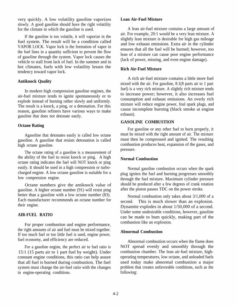
very quickly. A low volatility gasoline vaporizesslowly. A good gasoline should have the right volatilityfor the climate in which the gasoline is used.
If the gasoline is too volatile, it will vaporize in thefuel system. The result will be a condition calledVAPOR LOCK. Vapor lock is the formation of vapor inthe fuel lines in a quantity sufficient to prevent the flowof gasoline through the system. Vapor lock causes thevehicle to stall from lack of fuel. In the summer and inhot climates, fuels with low volatility lessen thetendency toward vapor lock.
Antiknock Quality
In modern high compression gasoline engines, theair-fuel mixture tends to ignite spontaneously or toexplode instead of burning rather slowly and uniformly.The result is a knock, a ping, or a detonation. For thisreason, gasoline refiners have various ways to makegasoline that does not detonate easily.
Octane Rating
Agasoline that detonates easily is called low octanegasoline. A gasoline that resists detonation is calledhigh octane gasoline.
The octane rating of a gasoline is a measurement ofthe ability of the fuel to resist knock or ping. A highoctane rating indicates the fuel will NOT knock or pingeasily. It should be used in a high compression or turbo-charged engine. A low octane gasoline is suitable for alow compression engine.
Octane numbers give the antiknock value ofgasoline. A higher octane number (91) will resist pingbetter than a gasoline with a low octane number (83).Each manufacturer recommends an octane number fortheir engine.
AIR-FUEL RATIO
For proper combustion and engine performance,the right amounts of air and fuel must be mixed together.If too much fuel or too little fuel is used, engine power,fuel economy, and efficiency are reduced.
For a gasoline engine, the perfect air to fuel ratio is15:1 (15 parts air to 1 part fuel by weight). Underconstant engine conditions, this ratio can help assurethat all fuel is burned during combustion. The fuelsystem must change the air-fuel ratio with the changesin engine-operating conditions.
Lean Air-Fuel Mixture
A lean air-fuel mixture contains a large amount ofair. For example, 20:1 would be a very lean mixture. Aslightly lean mixture is desirable for high gas mileageand low exhaust emissions. Extra air in the cylinderensures that all the fuel will be burned; however, toolean of a mixture can cause poor engine performance(lack of power, missing, and even engine damage).
Rich Air-Fuel Mixture
A rich air-fuel mixture contains a little more fuelmixed with the air. For gasoline, 8:1(8 parts air to 1 partfuel) is a very rich mixture. A slightly rich mixture tendsto increase power; however, it also increases fuelconsumption and exhaust emissions. An overly richmixture will reduce engine power, foul spark plugs, andcause incomplete burning (black smoke at engineexhaust).
GASOLINE COMBUSTION
For gasoline or any other fuel to burn properly, itmust be mixed with the right amount of air. The mixturemust then be compressed and ignited. The resultingcombustion produces heat, expansion of the gases, andpressure.
Normal Combustion
Normal gasoline combustion occurs when the sparkplug ignites the fuel and burning progresses smoothlythrough the fuel mixture. Maximum cylinder pressureshould be produced after a few degrees of crank rotationafter the piston passes TDC on the power stroke.
Normal combustion only takes about 3/1,000 of asecond. This is much slower than an explosion.Dynamite explodes in about 1/50,000 of a second.Under some undesirable conditions, however, gasolinecan be made to bum quickly, making part of thecombustion like an explosion.
Abnormal Combustion
Abnormal combustion occurs when the flame doesNOT spread evenly and smoothly through thecombustion chamber. The lean air-fuel mixture, high-operating temperatures, low octane, and unleaded fuelsused today make abnormal combustion a majorproblem that creates unfavorable conditions, such as thefollowing:
4-2
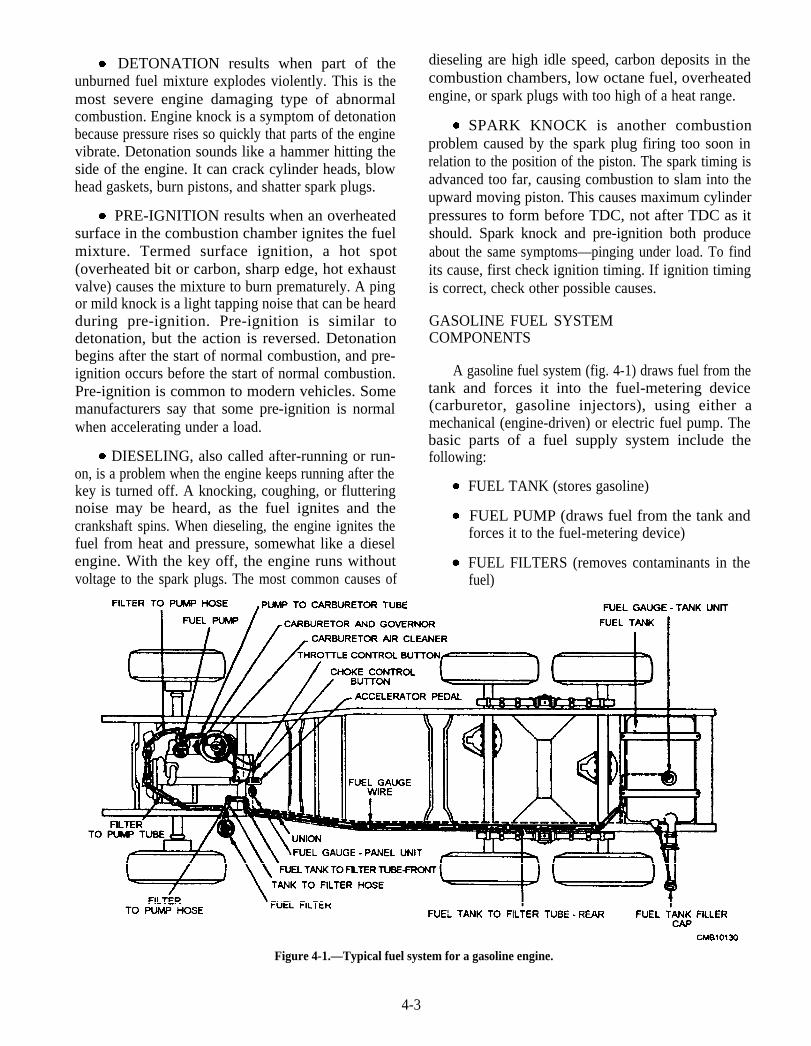
DETONATION results when part of theunburned fuel mixture explodes violently. This is themost severe engine damaging type of abnormalcombustion. Engine knock is a symptom of detonationbecause pressure rises so quickly that parts of the enginevibrate. Detonation sounds like a hammer hitting theside of the engine. It can crack cylinder heads, blowhead gaskets, burn pistons, and shatter spark plugs.
PRE-IGNITION results when an overheatedsurface in the combustion chamber ignites the fuelmixture. Termed surface ignition, a hot spot(overheated bit or carbon, sharp edge, hot exhaustvalve) causes the mixture to burn prematurely. A pingor mild knock is a light tapping noise that can be heardduring pre-ignition. Pre-ignition is similar todetonation, but the action is reversed. Detonationbegins after the start of normal combustion, and pre-ignition occurs before the start of normal combustion.Pre-ignition is common to modern vehicles. Somemanufacturers say that some pre-ignition is normalwhen accelerating under a load.
DIESELING, also called after-running or run-on, is a problem when the engine keeps running after thekey is turned off. A knocking, coughing, or flutteringnoise may be heard, as the fuel ignites and thecrankshaft spins. When dieseling, the engine ignites thefuel from heat and pressure, somewhat like a dieselengine. With the key off, the engine runs withoutvoltage to the spark plugs. The most common causes of
dieseling are high idle speed, carbon deposits in thecombustion chambers, low octane fuel, overheatedengine, or spark plugs with too high of a heat range.
SPARK KNOCK is another combustionproblem caused by the spark plug firing too soon inrelation to the position of the piston. The spark timing isadvanced too far, causing combustion to slam into theupward moving piston. This causes maximum cylinderpressures to form before TDC, not after TDC as itshould. Spark knock and pre-ignition both produceabout the same symptoms—pinging under load. To findits cause, first check ignition timing. If ignition timingis correct, check other possible causes.
GASOLINE FUEL SYSTEMCOMPONENTS
A gasoline fuel system (fig. 4-1) draws fuel from thetank and forces it into the fuel-metering device(carburetor, gasoline injectors), using either amechanical (engine-driven) or electric fuel pump. Thebasic parts of a fuel supply system include thefollowing:
FUEL TANK (stores gasoline)
FUEL PUMP (draws fuel from the tank andforces it to the fuel-metering device)
FUEL FILTERS (removes contaminants in thefuel)
Figure 4-1.—Typical fuel system for a gasoline engine.
4-3
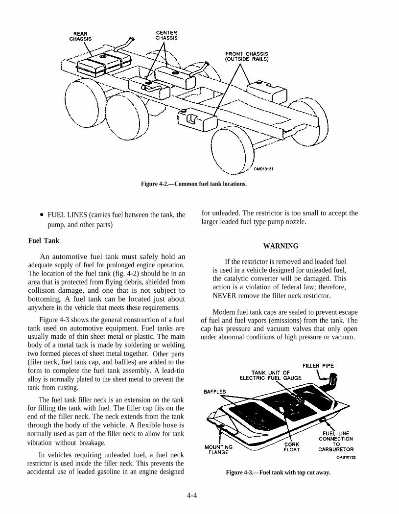
FUEL LINES (carries fuel between the tank, thepump, and other parts)
Fuel Tank
An automotive fuel tank must safely hold anadequate supply of fuel for prolonged engine operation.The location of the fuel tank (fig. 4-2) should be in anarea that is protected from flying debris, shielded fromcollision damage, and one that is not subject tobottoming. A fuel tank can be located just aboutanywhere in the vehicle that meets these requirements.
Figure 4-3 shows the general construction of a fueltank used on automotive equipment. Fuel tanks areusually made of thin sheet metal or plastic. The mainbody of a metal tank is made by soldering or weldingtwo formed pieces of sheet metal together. Other parts(filer neck, fuel tank cap, and baffles) are added to theform to complete the fuel tank assembly. A lead-tinalloy is normally plated to the sheet metal to prevent thetank from rusting.
The fuel tank filler neck is an extension on the tankfor filling the tank with fuel. The filler cap fits on theend of the filler neck. The neck extends from the tankthrough the body of the vehicle. A flexible hose isnormally used as part of the filler neck to allow for tankvibration without breakage.
In vehicles requiring unleaded fuel, a fuel neckrestrictor is used inside the filler neck. This prevents theaccidental use of leaded gasoline in an engine designed
for unleaded. The restrictor is too small to accept thelarger leaded fuel type pump nozzle.
WARNING
If the restrictor is removed and leaded fuelis used in a vehicle designed for unleaded fuel,the catalytic converter will be damaged. Thisaction is a violation of federal law; therefore,NEVER remove the filler neck restrictor.
Modern fuel tank caps are sealed to prevent escapeof fuel and fuel vapors (emissions) from the tank. Thecap has pressure and vacuum valves that only openunder abnormal conditions of high pressure or vacuum.
Figure 4-3.—Fuel tank with top cut away.
Figure 4-2.—Common fuel tank locations.
4-4
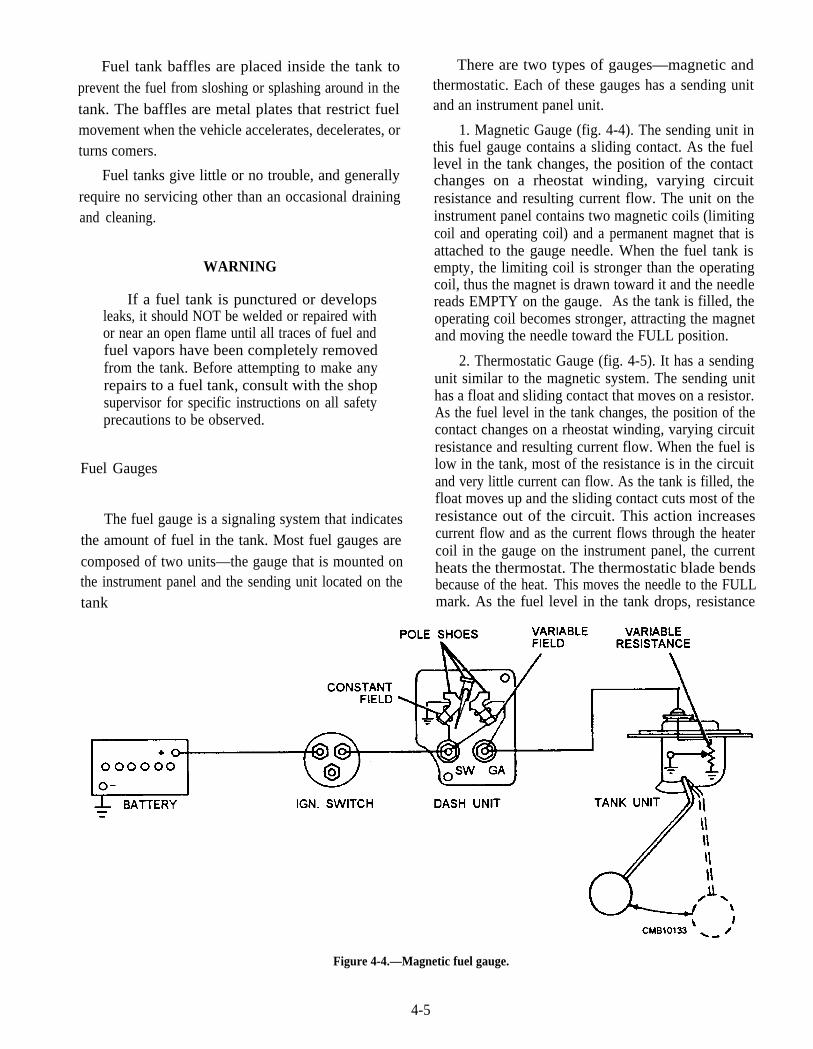
Fuel tank baffles are placed inside the tank toprevent the fuel from sloshing or splashing around in thetank. The baffles are metal plates that restrict fuelmovement when the vehicle accelerates, decelerates, orturns comers.
Fuel tanks give little or no trouble, and generallyrequire no servicing other than an occasional drainingand cleaning.
WARNING
If a fuel tank is punctured or developsleaks, it should NOT be welded or repaired withor near an open flame until all traces of fuel andfuel vapors have been completely removedfrom the tank. Before attempting to make anyrepairs to a fuel tank, consult with the shopsupervisor for specific instructions on all safetyprecautions to be observed.
Fuel Gauges
The fuel gauge is a signaling system that indicatesthe amount of fuel in the tank. Most fuel gauges arecomposed of two units—the gauge that is mounted onthe instrument panel and the sending unit located on thetank
There are two types of gauges—magnetic andthermostatic. Each of these gauges has a sending unitand an instrument panel unit.
1. Magnetic Gauge (fig. 4-4). The sending unit inthis fuel gauge contains a sliding contact. As the fuellevel in the tank changes, the position of the contactchanges on a rheostat winding, varying circuitresistance and resulting current flow. The unit on theinstrument panel contains two magnetic coils (limitingcoil and operating coil) and a permanent magnet that isattached to the gauge needle. When the fuel tank isempty, the limiting coil is stronger than the operatingcoil, thus the magnet is drawn toward it and the needlereads EMPTY on the gauge. As the tank is filled, theoperating coil becomes stronger, attracting the magnetand moving the needle toward the FULL position.
2. Thermostatic Gauge (fig. 4-5). It has a sendingunit similar to the magnetic system. The sending unithas a float and sliding contact that moves on a resistor.As the fuel level in the tank changes, the position of thecontact changes on a rheostat winding, varying circuitresistance and resulting current flow. When the fuel islow in the tank, most of the resistance is in the circuitand very little current can flow. As the tank is filled, thefloat moves up and the sliding contact cuts most of theresistance out of the circuit. This action increasescurrent flow and as the current flows through the heatercoil in the gauge on the instrument panel, the currentheats the thermostat. The thermostatic blade bendsbecause of the heat. This moves the needle to the FULLmark. As the fuel level in the tank drops, resistance
Figure 4-4.—Magnetic fuel gauge.
4-5

Figure 4-5.—Thermostatic fuel gauge: self-regulating.
4-6
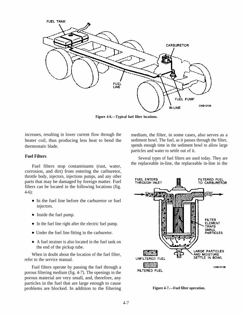
Figure 4-6.—Typical fuel filter locations.
increases, resulting in lower current flow through theheater coil, thus producing less heat to bend thethermostatic blade.
Fuel Filters
Fuel filters stop contaminants (rust, water,corrosion, and dirt) from entering the carburetor,throttle body, injectors, injections pumps, and any otherparts that may be damaged by foreign matter. Fuelfilters can be located in the following locations (fig.4-6):
A fuel strainer is also located in the fuel tank onthe end of the pickup tube.
In the fuel line right after the electric fuel pump.
Under the fuel line fitting in the carburetor.
Inside the fuel pump.
In the fuel line before the carburetor or fuelinjectors.
When in doubt about the location of the fuel filter,refer to the service manual.
Fuel filters operate by passing the fuel through aporous filtering medium (fig. 4-7). The openings in theporous material are very small, and, therefore, anyparticles in the fuel that are large enough to causeproblems are blocked. In addition to the filtering
medium, the filter, in some cases, also serves as asediment bowl. The fuel, as it passes through the filter,spends enough time in the sediment bowl to allow largeparticles and water to settle out of it.
Several types of fuel filters are used today. They arethe replaceable in-line, the replaceable in-line in the
Figure 4-7.—Fuel filter operation.
4-7
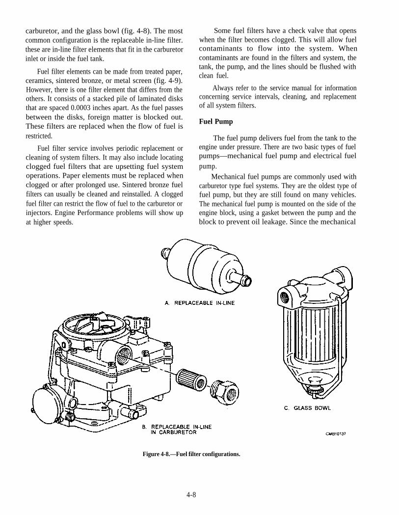
carburetor, and the glass bowl (fig. 4-8). The mostcommon configuration is the replaceable in-line filter.these are in-line filter elements that fit in the carburetorinlet or inside the fuel tank.
Fuel filter elements can be made from treated paper,ceramics, sintered bronze, or metal screen (fig. 4-9).However, there is one filter element that differs from theothers. It consists of a stacked pile of laminated disksthat are spaced 0.0003 inches apart. As the fuel passesbetween the disks, foreign matter is blocked out.These filters are replaced when the flow of fuel isrestricted.
Fuel filter service involves periodic replacement orcleaning of system filters. It may also include locatingclogged fuel filters that are upsetting fuel systemoperations. Paper elements must be replaced whenclogged or after prolonged use. Sintered bronze fuelfilters can usually be cleaned and reinstalled. A cloggedfuel filter can restrict the flow of fuel to the carburetor orinjectors. Engine Performance problems will show upat higher speeds.
Some fuel filters have a check valve that openswhen the filter becomes clogged. This will allow fuelcontaminants to flow into the system. Whencontaminants are found in the filters and system, thetank, the pump, and the lines should be flushed withclean fuel.
Always refer to the service manual for informationconcerning service intervals, cleaning, and replacementof all system filters.
Fuel Pump
The fuel pump delivers fuel from the tank to theengine under pressure. There are two basic types of fuelpumps—mechanical fuel pump and electrical fuelpump.
Mechanical fuel pumps are commonly used withcarburetor type fuel systems. They are the oldest type offuel pump, but they are still found on many vehicles.The mechanical fuel pump is mounted on the side of theengine block, using a gasket between the pump and theblock to prevent oil leakage. Since the mechanical
Figure 4-8.—Fuel filter configurations.
4-8
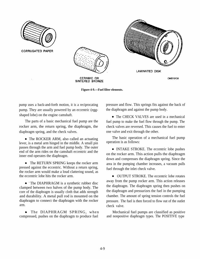
Figure 4-9.—Fuel filter elements.
pump uses a back-and-forth motion, it is a reciprocatingpump. They are usually powered by an eccentric (egg-shaped lobe) on the engine camshaft.
The parts of a basic mechanical fuel pump are therocker arm, the return spring, the diaphragm, thediaphragm spring, and the check valves.
The ROCKER ARM, also called an actuatinglever, is a metal arm hinged in the middle. A small pinpasses through the arm and fuel pump body. The outerend of the arm rides on the camshaft eccentric and theinner end operates the diaphragm.
The RETURN SPRING keeps the rocker armpressed against the eccentric. Without a return spring,the rocker arm would make a loud clattering sound, asthe eccentric lobe hits the rocker arm.
The DIAPHRAGM is a synthetic rubber discclamped between two halves of the pump body. Thecore of the diaphragm is usually cloth that adds strengthand durability. A metal pull rod is mounted on thediaphragm to connect the diaphragm with the rockerarm.
The DIAPHRAGM SPRING, whencompressed, pushes on the diaphragm to produce fuel
pressure and flow. This springs fits against the back ofthe diaphragm and against the pump body.
The CHECK VALVES are used in a mechanicalfuel pump to make the fuel flow through the pump. Thecheck valves are reversed. This causes the fuel to enterone valve and exit through the other.
The basic operation of a mechanical fuel pumpoperation is as follows:
INTAKE STROKE. The eccentric lobe pusheson the rocker arm. This action pulls the diaphragmdown and compresses the diaphragm spring. Since thearea in the pumping chamber increases, a vacuum pullsfuel through the inlet check valve.
OUTPUT STROKE. The eccentric lobe rotatesaway from the pump rocker arm. This action releasesthe diaphragm. The diaphragm spring then pushes onthe diaphragm and pressurizes the fuel in the pumpingchamber. The amount of spring tension controls the fuelpressure. The fuel is then forced to flow out of the outletcheck valve.
Mechanical fuel pumps are classified as positiveand nonpositive diaphragm types. The POSITIVE type
4-9

Figure 4-10.—Mechanical positive fuel pump installation.
(fig. 4-10) continues to pump fuel even when thecarburetor bowl is filled; therefore, a method ofbypassing the fuel back to the tank is required. TheNONPOSITIVE type (fig. 4-11) is the one usuallyfound in a gasoline engine. It delivers fuel to thecarburetor only when it is needed for the requirementsof the engine.
An electric fuel pump, like the mechanical pump,produces fuel pressure and flow for the fuel-meteringsection of a fuel system.
Electric fuel pumps are commonly used in gasolinefuel systems. They can be located inside the fuel tank aspart of the fuel pickupsending unit. Also, it can belocated in the fuel line between the tank and the engine.
The advantages an electric fuel pump has over themechanical fuel pump are as follows:
An electric fuel pump can produce almost instantfuel pressure. A mechanical pump slowly buildspressure as the engine is cranked for starting.
Most electric fuel pumps are a rotary type. Thisproduces a smoother flow of fuel (less pressurepulsations) than a reciprocating, mechanical pump.
Since most electric pumps are located away fromthe engine, they help prevent vapor lock. An electricfuel pump pressurizes all of the fuel line near the engineheat. This helps avoid vapor lock because pressuremakes it more difficult for bubbles to form in the fuel.
Electric rotary fuel pumps include the impeller, theroller vane, and the sliding vane types. They use acircular or spinning motion to produce pressure.
An impeller electric fuel pump is a centrifugalpump, normally located inside the fuel tank. This pumpused a small motor to spin the impeller (fan blade). Theimpeller blades cause fuel to fly outward due tocentrifugal force. This produces enough pressure tomove the fuel through the fuel lines.
A roller vane electric fuel pump (fig. 4-12) is apositive displacement pump (each pump rotation movesa specific amount of fuel). This pump is located in themain fuel line. Small rollers and an offset mounted rotordisc produce fuel pressure in the pump. When the rotordisc and rollers spin, they pull fuel to one side. The fuelis then trapped and pushed to a smaller area on theopposite side of the pump housing. This actionsqueezes the fuel between the rollers and the fuel flows
Figure 4-12.—Vane-type electric pump.
4-10

Figure 4-11.—Mechanical nonpositive fuel pump.
4-11
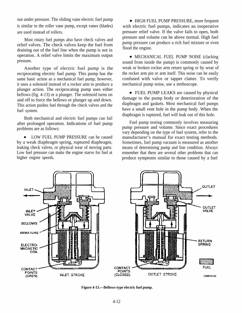
out under pressure. The sliding vane electric fuel pumpis similar to the roller vane pump, except vanes (blades)are used instead of rollers.
Most rotary fuel pumps also have check valves andrelief valves. The check valves keep the fuel fromdraining out of the fuel line when the pump is not inoperation. A relief valve limits the maximum outputpressure.
Another type of electric fuel pump is thereciprocating electric fuel pump. This pump has thesame basic action as a mechanical fuel pump; however,it uses a solenoid instead of a rocker arm to produce aplunger action. The reciprocating pump uses eitherbellows (fig. 4-13) or a plunger. The solenoid turns onand off to force the bellows or plunger up and down.This action pushes fuel through the check valves and thefuel system.
Both mechanical and electric fuel pumps can failafter prolonged operation. Indications of fuel pumpproblems are as follows:
LOW FUEL PUMP PRESSURE can be causedby a weak diaphragm spring, ruptured diaphragm,leaking check valves, or physical wear of moving parts.Low fuel pressure can make the engine starve for fuel athigher engine speeds.
HIGH FUEL PUMP PRESSURE, more frequentwith electric fuel pumps, indicates an inoperativepressure relief valve. If the valve fails to open, bothpressure and volume can be above normal. High fuelpump pressure can produce a rich fuel mixture or evenflood the engine.
MECHANICAL FUEL PUMP NOISE (clackingsound from inside the pump) is commonly caused byweak or broken rocker arm return spring or by wear ofthe rocker arm pin or arm itself. This noise can be easilyconfused with valve or tappet clatter. To verifymechanical pump noise, use a stethoscope.
FUEL PUMP LEAKS are caused by physicaldamage to the pump body or deterioration of thediaphragm and gaskets. Most mechanical fuel pumpshave a small vent hole in the pump body. When thediaphragm is ruptured, fuel will leak out of this hole.
Fuel pump testing commonly involves measuringpump pressure and volume. Since exact proceduresvary depending on the type of fuel system, refer to themanufacturer’s manual for exact testing methods.Sometimes, fuel pump vacuum is measured as anothermeans of determining pump and line condition. Alwaysremember that there are several other problems that canproduce symptoms similar to those caused by a fuel
Figure 4-13.—Bellows-type electric fuel pump.
4-12
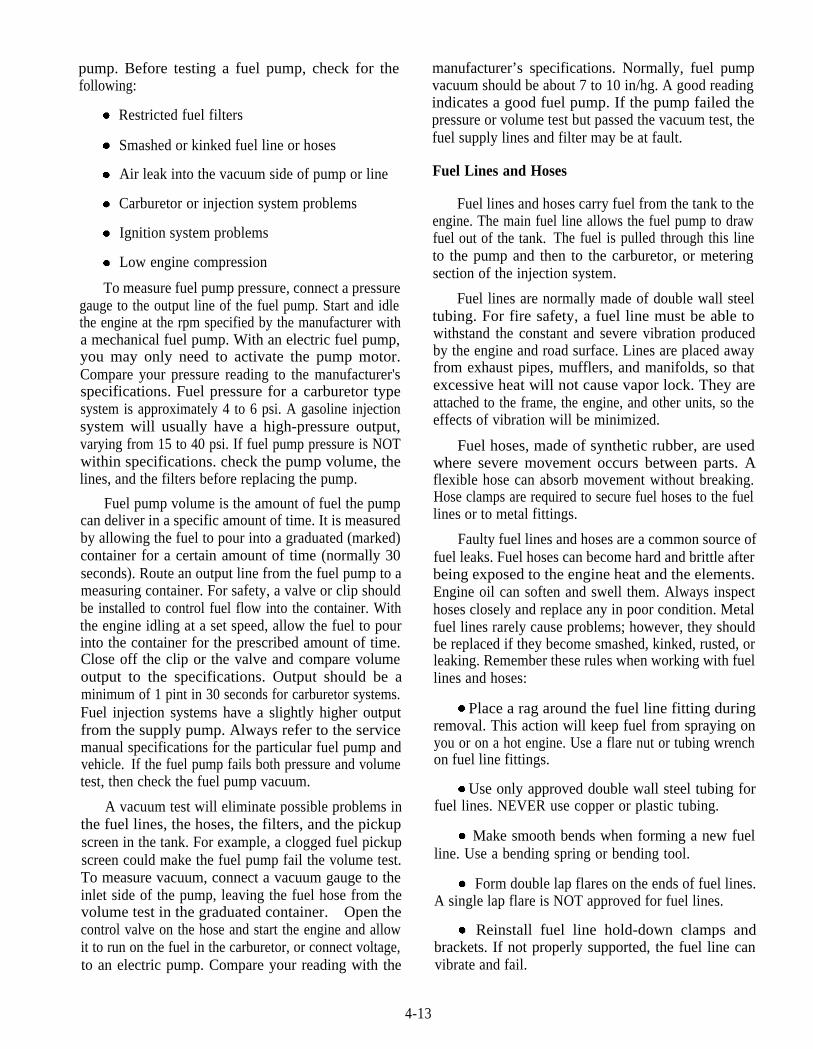
pump. Before testing a fuel pump, check for thefollowing:
Restricted fuel filters
Smashed or kinked fuel line or hoses
Air leak into the vacuum side of pump or line
Carburetor or injection system problems
Ignition system problems
Low engine compression
To measure fuel pump pressure, connect a pressuregauge to the output line of the fuel pump. Start and idlethe engine at the rpm specified by the manufacturer witha mechanical fuel pump. With an electric fuel pump,you may only need to activate the pump motor.Compare your pressure reading to the manufacturer'sspecifications. Fuel pressure for a carburetor typesystem is approximately 4 to 6 psi. A gasoline injectionsystem will usually have a high-pressure output,varying from 15 to 40 psi. If fuel pump pressure is NOTwithin specifications. check the pump volume, thelines, and the filters before replacing the pump.
Fuel pump volume is the amount of fuel the pumpcan deliver in a specific amount of time. It is measuredby allowing the fuel to pour into a graduated (marked)container for a certain amount of time (normally 30seconds). Route an output line from the fuel pump to ameasuring container. For safety, a valve or clip shouldbe installed to control fuel flow into the container. Withthe engine idling at a set speed, allow the fuel to pourinto the container for the prescribed amount of time.Close off the clip or the valve and compare volumeoutput to the specifications. Output should be aminimum of 1 pint in 30 seconds for carburetor systems.Fuel injection systems have a slightly higher outputfrom the supply pump. Always refer to the servicemanual specifications for the particular fuel pump andvehicle. If the fuel pump fails both pressure and volumetest, then check the fuel pump vacuum.
A vacuum test will eliminate possible problems inthe fuel lines, the hoses, the filters, and the pickupscreen in the tank. For example, a clogged fuel pickupscreen could make the fuel pump fail the volume test.To measure vacuum, connect a vacuum gauge to theinlet side of the pump, leaving the fuel hose from thevolume test in the graduated container. Open thecontrol valve on the hose and start the engine and allowit to run on the fuel in the carburetor, or connect voltage,to an electric pump. Compare your reading with the
manufacturer’s specifications. Normally, fuel pumpvacuum should be about 7 to 10 in/hg. A good readingindicates a good fuel pump. If the pump failed thepressure or volume test but passed the vacuum test, thefuel supply lines and filter may be at fault.
Fuel Lines and Hoses
Fuel lines and hoses carry fuel from the tank to theengine. The main fuel line allows the fuel pump to drawfuel out of the tank. The fuel is pulled through this lineto the pump and then to the carburetor, or meteringsection of the injection system.
Fuel lines are normally made of double wall steeltubing. For fire safety, a fuel line must be able towithstand the constant and severe vibration producedby the engine and road surface. Lines are placed awayfrom exhaust pipes, mufflers, and manifolds, so thatexcessive heat will not cause vapor lock. They areattached to the frame, the engine, and other units, so theeffects of vibration will be minimized.
Fuel hoses, made of synthetic rubber, are usedwhere severe movement occurs between parts. Aflexible hose can absorb movement without breaking.Hose clamps are required to secure fuel hoses to the fuellines or to metal fittings.
Faulty fuel lines and hoses are a common source offuel leaks. Fuel hoses can become hard and brittle afterbeing exposed to the engine heat and the elements.Engine oil can soften and swell them. Always inspecthoses closely and replace any in poor condition. Metalfuel lines rarely cause problems; however, they shouldbe replaced if they become smashed, kinked, rusted, orleaking. Remember these rules when working with fuellines and hoses:
Place a rag around the fuel line fitting duringremoval. This action will keep fuel from spraying onyou or on a hot engine. Use a flare nut or tubing wrenchon fuel line fittings.
Use only approved double wall steel tubing forfuel lines. NEVER use copper or plastic tubing.
Make smooth bends when forming a new fuelline. Use a bending spring or bending tool.
Form double lap flares on the ends of fuel lines.A single lap flare is NOT approved for fuel lines.
Reinstall fuel line hold-down clamps andbrackets. If not properly supported, the fuel line canvibrate and fail.
4-13
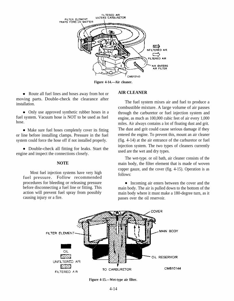
Figure 4-14.—Air cleaner.
Route all fuel lines and hoses away from hot ormoving parts. Double-check the clearance afterinstallation.
Only use approved synthetic rubber hoses in afuel system. Vacuum hose is NOT to be used as fuelhose.
Make sure fuel hoses completely cover its fittingor line before installing clamps. Pressure in the fuelsystem could force the hose off if not installed properly.
Double-check all fitting for leaks. Start theengine and inspect the connections closely.
NOTE
Most fuel injection systems have very highfuel pressure. Follow recommendedprocedures for bleeding or releasing pressurebefore disconnecting a fuel line or fitting. Thisaction will prevent fuel spray from possiblycausing injury or a fire.
AIR CLEANER
The fuel system mixes air and fuel to produce acombustible mixture. A large volume of air passesthrough the carburetor or fuel injection system andengine, as much as 100,000 cubic feet of air every 1,000miles. Air always contains a lot of floating dust and grit.The dust and grit could cause serious damage if theyentered the engine. To prevent this, mount an air cleaner(fig. 4-14) at the air entrance of the carburetor or fuelinjection system. The two types of cleaners currentlyused are the wet and dry types.
The wet-type. or oil bath, air cleaner consists of themain body, the filter element that is made of wovencopper gauze, and the cover (fig. 4-15). Operation is asfollows:
Incoming air enters between the cover and themain body. The air is pulled down to the bottom of themain body where it must make a 180-degree turn, as itpasses over the oil reservoir.
Figure 4-15.—Wet-type air filter.
4-14
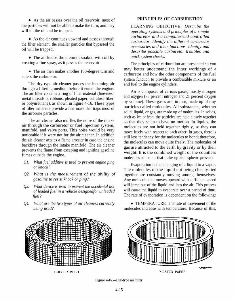
As the air passes over the oil reservoir, most ofthe particles will not be able to make the turn, and theywill hit the oil and be trapped.
As the air continues upward and passes throughthe filter element, the smaller particles that bypassed theoil will be trapped.
The air keeps the element soaked with oil bycreating a fine spray, as it passes the reservoir.
The air then makes another 180-degree turn andenters the carburetor.
The dry-type air cleaner passes the incoming airthrough a filtering medium before it enters the engine.The air filter contains a ring of filter material (fine-meshmetal threads or ribbons, pleated paper, cellulose fiber,or polyurethane), as shown in figure 4-16. These typesof filter materials provide a fine maze that traps most ofthe airborne particles.
The air cleaner also muffles the noise of the intakeair through the carburetor or fuel injection system,manifold, and valve ports. This noise would be verynoticeable if it were not for the air cleaner. In additionthe air cleaner acts as a flame arrester in case the enginebackfires through the intake manifold. The air cleanerprevents the flame from escaping and igniting gasolinefumes outside the engine.
Q1. What fuel additive is used to prevent engine pingor knock?
Q2. What is the measurement of the ability ofgasoline to resist knock or ping?
Q3. What device is used to prevent the accidental useof leaded fuel in a vehicle designedfor unleadedfuel?
Q4. What are the two types of air cleaners currentlybeing used?
PRINCIPLES OF CARBURETION
LEARNING OBJECTIVE: Describe theoperating systems and principles of a simplecarburetor and a computerized controlledcarburetor. Identify the different carburetoraccessories and their functions. Identify anddescribe possible carburetor troubles andquick system checks.
The principles of carburetion are presented so youmay better understand the inner workings of acarburetor and how the other components of the fuelsystem function to provide a combustible mixture or airand fuel to the engine cylinders.
Air is composed of various gases, mostly nitrogenand oxygen (78 percent nitrogen and 21 percent oxygenby volume). These gases are, in turn, made up of tinyparticles called molecules. All substances, whethersolid, liquid, or gas, are made up of molecules. In solids,such as ice or iron, the particles are held closely togetherso that they seem to have no motion. In liquids, themolecules are not held together tightly, so they canmove freely with respect to each other. In gases, there isstill less tendency for the molecules to bond; therefore,the molecules can move quite freely. The molecules ofgas are attracted to the earth by gravity or by theirweight. It is the combined weight of the countlessmolecules in the air that make up atmospheric pressure.
Evaporation is the changing of a liquid to a vapor.The molecules of the liquid not being closely tiedtogether are constantly moving among themselves.Any molecule that moves upward with sufficient speedwill jump out of the liquid and into the air. This processwill cause the liquid to evaporate over a period of time.The rate of evaporation is dependent on the following:
TEMPERATURE. The rate of movement of themolecules increase with temperature. Because of this,
Figure 4-16.—Dry-type air filter.
4-15
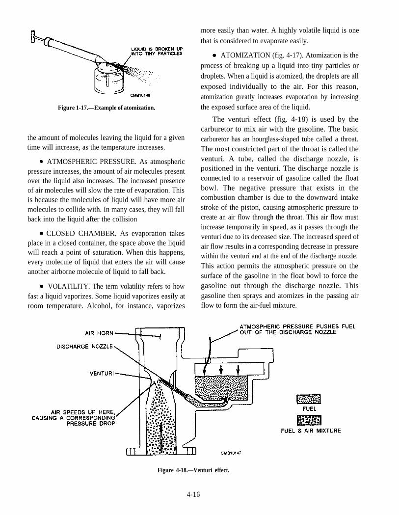
more easily than water. A highly volatile liquid is onethat is considered to evaporate easily.
ATOMIZATION (fig. 4-17). Atomization is theprocess of breaking up a liquid into tiny particles ordroplets. When a liquid is atomized, the droplets are allexposed individually to the air. For this reason,atomization greatly increases evaporation by increasingthe exposed surface area of the liquid.Figure 1-17.—Example of atomization.
the amount of molecules leaving the liquid for a giventime will increase, as the temperature increases.
ATMOSPHERIC PRESSURE. As atmosphericpressure increases, the amount of air molecules presentover the liquid also increases. The increased presenceof air molecules will slow the rate of evaporation. Thisis because the molecules of liquid will have more airmolecules to collide with. In many cases, they will fallback into the liquid after the collision
CLOSED CHAMBER. As evaporation takesplace in a closed container, the space above the liquidwill reach a point of saturation. When this happens,every molecule of liquid that enters the air will causeanother airborne molecule of liquid to fall back.
VOLATILITY. The term volatility refers to howfast a liquid vaporizes. Some liquid vaporizes easily atroom temperature. Alcohol, for instance, vaporizes
The venturi effect (fig. 4-18) is used by thecarburetor to mix air with the gasoline. The basiccarburetor has an hourglass-shaped tube called a throat.The most constricted part of the throat is called theventuri. A tube, called the discharge nozzle, ispositioned in the venturi. The discharge nozzle isconnected to a reservoir of gasoline called the floatbowl. The negative pressure that exists in thecombustion chamber is due to the downward intakestroke of the piston, causing atmospheric pressure tocreate an air flow through the throat. This air flow mustincrease temporarily in speed, as it passes through theventuri due to its deceased size. The increased speed ofair flow results in a corresponding decrease in pressurewithin the venturi and at the end of the discharge nozzle.This action permits the atmospheric pressure on thesurface of the gasoline in the float bowl to force thegasoline out through the discharge nozzle. Thisgasoline then sprays and atomizes in the passing airflow to form the air-fuel mixture.
Figure 4-18.—Venturi effect.
4-16
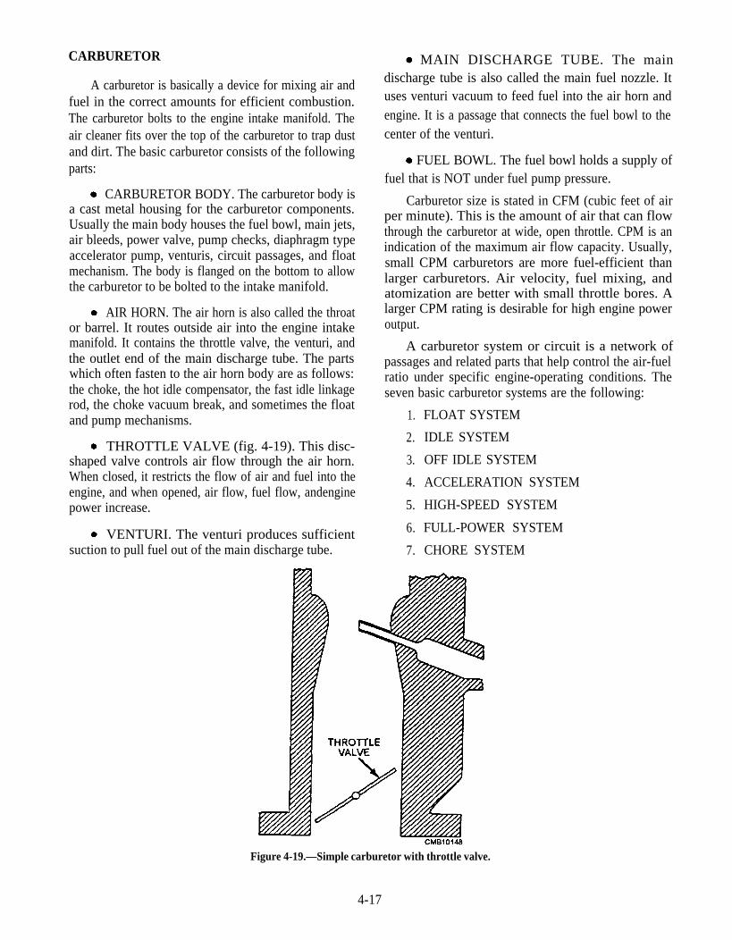
CARBURETOR
A carburetor is basically a device for mixing air andfuel in the correct amounts for efficient combustion.The carburetor bolts to the engine intake manifold. Theair cleaner fits over the top of the carburetor to trap dustand dirt. The basic carburetor consists of the followingparts:
CARBURETOR BODY. The carburetor body isa cast metal housing for the carburetor components.Usually the main body houses the fuel bowl, main jets,air bleeds, power valve, pump checks, diaphragm typeaccelerator pump, venturis, circuit passages, and floatmechanism. The body is flanged on the bottom to allowthe carburetor to be bolted to the intake manifold.
AIR HORN. The air horn is also called the throator barrel. It routes outside air into the engine intakemanifold. It contains the throttle valve, the venturi, andthe outlet end of the main discharge tube. The partswhich often fasten to the air horn body are as follows:the choke, the hot idle compensator, the fast idle linkagerod, the choke vacuum break, and sometimes the floatand pump mechanisms.
THROTTLE VALVE (fig. 4-19). This disc-shaped valve controls air flow through the air horn.When closed, it restricts the flow of air and fuel into theengine, and when opened, air flow, fuel flow, andenginepower increase.
VENTURI. The venturi produces sufficientsuction to pull fuel out of the main discharge tube.
A carburetor system or circuit is a network ofpassages and related parts that help control the air-fuelratio under specific engine-operating conditions. Theseven basic carburetor systems are the following:
1. FLOAT SYSTEM
2. IDLE SYSTEM
3. OFF IDLE SYSTEM
4. ACCELERATION SYSTEM
5. HIGH-SPEED SYSTEM
6. FULL-POWER SYSTEM
7. CHORE SYSTEM
MAIN DISCHARGE TUBE. The maindischarge tube is also called the main fuel nozzle. Ituses venturi vacuum to feed fuel into the air horn andengine. It is a passage that connects the fuel bowl to thecenter of the venturi.
FUEL BOWL. The fuel bowl holds a supply offuel that is NOT under fuel pump pressure.
Carburetor size is stated in CFM (cubic feet of airper minute). This is the amount of air that can flowthrough the carburetor at wide, open throttle. CPM is anindication of the maximum air flow capacity. Usually,small CPM carburetors are more fuel-efficient thanlarger carburetors. Air velocity, fuel mixing, andatomization are better with small throttle bores. Alarger CPM rating is desirable for high engine poweroutput.
Figure 4-19.—Simple carburetor with throttle valve.
4-17
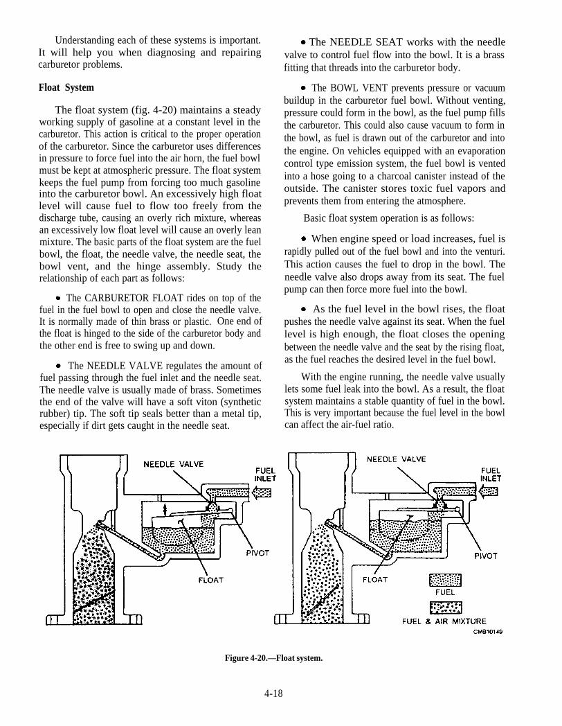
Understanding each of these systems is important.It will help you when diagnosing and repairingcarburetor problems.
Float System
The float system (fig. 4-20) maintains a steadyworking supply of gasoline at a constant level in thecarburetor. This action is critical to the proper operationof the carburetor. Since the carburetor uses differencesin pressure to force fuel into the air horn, the fuel bowlmust be kept at atmospheric pressure. The float systemkeeps the fuel pump from forcing too much gasolineinto the carburetor bowl. An excessively high floatlevel will cause fuel to flow too freely from thedischarge tube, causing an overly rich mixture, whereasan excessively low float level will cause an overly leanmixture. The basic parts of the float system are the fuelbowl, the float, the needle valve, the needle seat, thebowl vent, and the hinge assembly. Study therelationship of each part as follows:
The CARBURETOR FLOAT rides on top of thefuel in the fuel bowl to open and close the needle valve.It is normally made of thin brass or plastic. One end ofthe float is hinged to the side of the carburetor body andthe other end is free to swing up and down.
The NEEDLE VALVE regulates the amount offuel passing through the fuel inlet and the needle seat.The needle valve is usually made of brass. Sometimesthe end of the valve will have a soft viton (syntheticrubber) tip. The soft tip seals better than a metal tip,especially if dirt gets caught in the needle seat.
The NEEDLE SEAT works with the needlevalve to control fuel flow into the bowl. It is a brassfitting that threads into the carburetor body.
The BOWL VENT prevents pressure or vacuumbuildup in the carburetor fuel bowl. Without venting,pressure could form in the bowl, as the fuel pump fillsthe carburetor. This could also cause vacuum to form inthe bowl, as fuel is drawn out of the carburetor and intothe engine. On vehicles equipped with an evaporationcontrol type emission system, the fuel bowl is ventedinto a hose going to a charcoal canister instead of theoutside. The canister stores toxic fuel vapors andprevents them from entering the atmosphere.
Basic float system operation is as follows:
When engine speed or load increases, fuel israpidly pulled out of the fuel bowl and into the venturi.This action causes the fuel to drop in the bowl. Theneedle valve also drops away from its seat. The fuelpump can then force more fuel into the bowl.
As the fuel level in the bowl rises, the floatpushes the needle valve against its seat. When the fuellevel is high enough, the float closes the openingbetween the needle valve and the seat by the rising float,as the fuel reaches the desired level in the fuel bowl.
With the engine running, the needle valve usuallylets some fuel leak into the bowl. As a result, the floatsystem maintains a stable quantity of fuel in the bowl.This is very important because the fuel level in the bowlcan affect the air-fuel ratio.
Figure 4-20.—Float system.
4-18
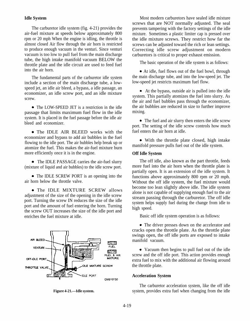
Idle System
The carburetor idle system (fig. 4-21) provides theair-fuel mixture at speeds below approximately 800rpm or 20 mph When the engine is idling, the throttle isalmost closed Air flow through the air horn is restrictedto produce enough vacuum in the venturi. Since venturivacuum is too low to pull fuel from the main dischargetube, the high intake manifold vacuum BELOW thethrottle plate and the idle circuit are used to feed fuelinto the air horn.
The fundamental parts of the carburetor idle systeminclude a section of the main discharge tube, a low-speed jet, an idle air bleed, a bypass, a idle passage, aneconomizer, an idle screw port, and an idle mixturescrew.
The LOW-SPEED JET is a restriction in the idlepassage that limits maximum fuel flow in the idlesystem. It is placed in the fuel passage before the idle airbleed and economizer.
The IDLE AIR BLEED works with theeconomizer and bypass to add air bubbles in the fuelflowing to the idle port. The air bubbles help break up oratomize the fuel. This makes the air-fuel mixture burnmore efficiently once it is in the engine.
The IDLE PASSAGE carries the air-fuel slurry(mixture of liquid and air bubbles) to the idle screw port.
The IDLE SCREW PORT is an opening into theair horn below the throttle valve.
The IDLE MIXTURE SCREW allowsadjustment of the size of the opening in the idle screwport. Turning the screw IN reduces the size of the idleport and the amount of fuel entering the horn. Turningthe screw OUT increases the size of the idle port andenriches the fuel mixture at idle.
Figure 4-21.—Idle system.
Most modern carburetors have sealed idle mixturescrews that are NOT normally adjusted. The sealprevents tampering with the factory settings of the idlemixture. Sometimes a plastic limiter cap is pressed overthe idle mixture screws. They restrict how far thescrews can be adjusted toward the rich or lean settings.Correcting idle screw adjustment on moderncarburetors is critical to proper exhaust emission.
The basic operation of the idle system is as follows:
At idle, fuel flows out of the fuel bowl, throughthe main discharge tube, and into the low-speed jet. Thelow-speed jet restricts maximum fuel flow.
At the bypass, outside air is pulled into the idlesystem. This partially atomizes the fuel into slurry. Asthe air and fuel bubbles pass through the economizer,the air bubbles are reduced in size to further improvemixing.
The fuel and air slurry then enters the idle screwport. The setting of the idle screw controls how muchfuel enters the air horn at idle.
With the throttle plate closed, high intakemanifold pressure pulls fuel out of the idle system.
Off Idle System
The off idle, also known as the part throttle, feedsmore fuel into the air horn when the throttle plate ispartially open. It is an extension of the idle system. Itfunctions above approximately 800 rpm or 20 mph.Without the off idle system, the fuel mixture wouldbecome too lean slightly above idle. The idle systemalone is not capable of supplying enough fuel to the airstream passing through the carburetor. The off idlesystem helps supply fuel during the change from idle tohigh speed.
Basic off idle system operation is as follows:
The driver presses down on the accelerator andcracks open the throttle plate. As the throttle plateswings open, the off idle ports are exposed to intakemanifold vacuum.
Vacuum then begins to pull fuel out of the idlescrew and the off idle port. This action provides enoughextra fuel to mix with the additional air flowing aroundthe throttle plate.
Acceleration System
The carburetor acceleration system, like the off idlesystem, provides extra fuel when changing from the idle
4-19
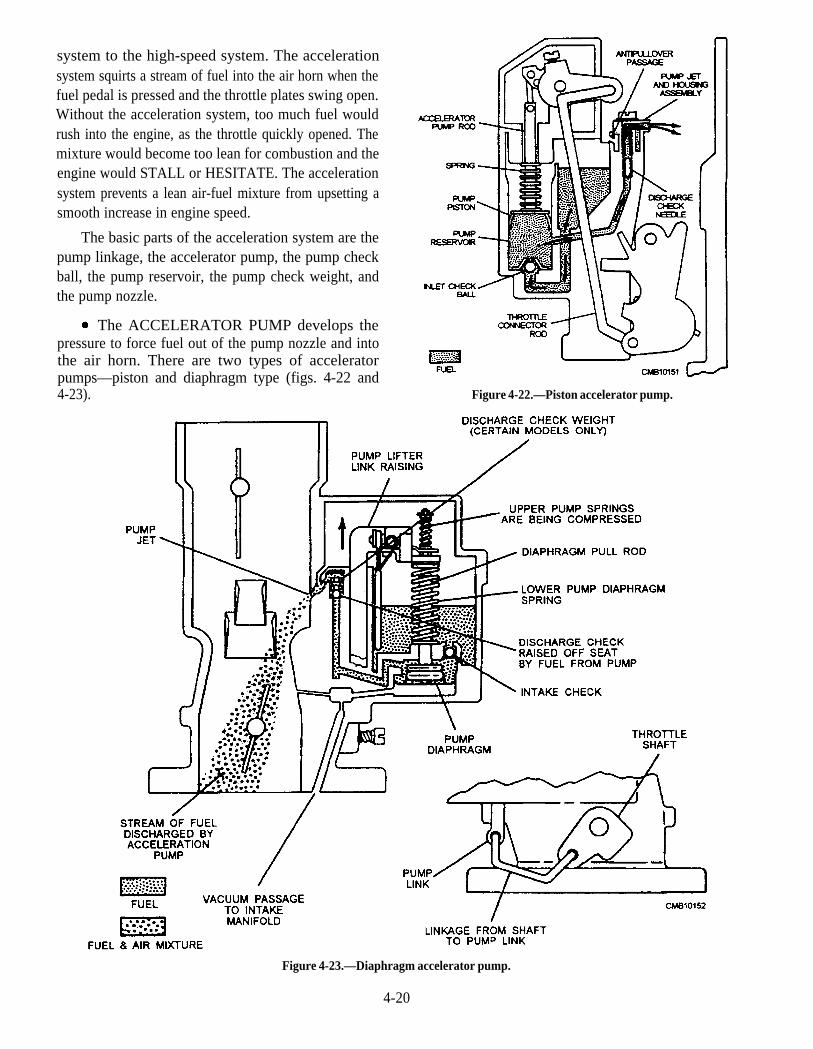
system to the high-speed system. The accelerationsystem squirts a stream of fuel into the air horn when thefuel pedal is pressed and the throttle plates swing open.Without the acceleration system, too much fuel wouldrush into the engine, as the throttle quickly opened. Themixture would become too lean for combustion and theengine would STALL or HESITATE. The accelerationsystem prevents a lean air-fuel mixture from upsetting asmooth increase in engine speed.
The basic parts of the acceleration system are thepump linkage, the accelerator pump, the pump checkball, the pump reservoir, the pump check weight, andthe pump nozzle.
The ACCELERATOR PUMP develops thepressure to force fuel out of the pump nozzle and intothe air horn. There are two types of acceleratorpumps—piston and diaphragm type (figs. 4-22 and4-23). Figure 4-22.—Piston accelerator pump.
Figure 4-23.—Diaphragm accelerator pump.
4-20
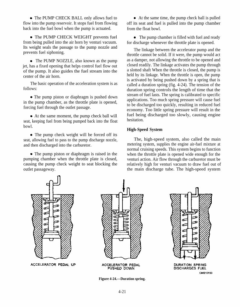
The PUMP CHECK BALL only allows fuel toflow into the pump reservoir. It stops fuel from flowingback into the fuel bowl when the pump is actuated.
The PUMP CHECK WEIGHT prevents fuelfrom being pulled into the air horn by venturi vacuum.Its weight seals the passage to the pump nozzle andprevents fuel siphoning.
The PUMP NOZZLE, also known as the pumpjet, has a fixed opening that helps control fuel flow outof the pump. It also guides the fuel stream into thecenter of the air horn.
The basic operation of the acceleration system is asfollows:
The pump piston or diaphragm is pushed downin the pump chamber, as the throttle plate is opened,forcing fuel through the outlet passage.
At the same moment, the pump check ball willseat, keeping fuel from being pumped back into the floatbowl.
The pump check weight will be forced off itsseat, allowing fuel to pass to the pump discharge nozzle,and then discharged into the carburetor.
The pump piston or diaphragm is raised in thepumping chamber when the throttle plate is closed,causing the pump check weight to seat blocking theoutlet passageway.
At the same time, the pump check ball is pulledoff its seat and fuel is pulled into the pump chamberfrom the float bowl.
The pump chamber is filled with fuel and readyfor discharge whenever the throttle plate is opened.
The linkage between the accelerator pump and thethrottle cannot be solid. If it were, the pump would actas a damper, not allowing the throttle to be opened andclosed readily. The linkage activates the pump througha slotted shaft When the throttle is closed, the pump isheld by its linkage. When the throttle is open, the pumpis activated by being pushed down by a spring that iscalled a duration spring (fig. 4-24). The tension of theduration spring controls the length of time that thestream of fuel lasts. The spring is calibrated to specificapplications. Too much spring pressure will cause fuelto be discharged too quickly, resulting in reduced fueleconomy. Too little spring pressure will result in thefuel being discharged too slowly, causing enginehesitation.
High-Speed System
The, high-speed system, also called the mainmetering system, supplies the engine air-fuel mixture atnormal cruising speeds. This system begins to functionwhen the throttle plate is opened wide enough for theventuri action. Air flow through the carburetor must berelatively high for venturi vacuum to draw fuel out ofthe main discharge tube. The high-speed system
Figure 4-24.—Duration spring.
4-21

provides the leanest, most fuel efficient air-fuel ratio. Itfunctions from about 20 to 55 mph or 2,000 to 3,000rpm.
The high-speed system is the simplest system. Itconsists of the high-speed jet, the main dischargepassage, the emulsion tube, the air bleed, and theventuri.
The HIGH-SPEED JET is a fitting with aprecision hole drilled into the center. This fitting screwsinto a threaded hole in the fuel bowl. One jet is used foreach air horn. The hole size determines how much fuelflows through the system. A number is stamped on thehigh-speed jet to denote the diameter of the hole. Sincejet numbering systems vary, refer to the manufacturer’smanual for information on jet size.
The EMULSION TUBE and AIR BLEED addair to the fuel flowing through the main discharge tube.The premixing of air with fuel helps the fuel atomize, asit is discharged into the air horn.
The VENTURI is the hourglass shape, formed inthe side of the carburetor air horn. One or two boosterventuris (fig. 4-25) can be added inside the primaryventuri to increase vacuum at lower engine speeds.
Figure 4-25.—Booster venturi
The basic operation of the high-speed system is asfollows:
When the engine speed is high enough, air flowthrough the carburetor forms a high vacuum in theventuri. The vacuum pulls fuel through the mainmetering system.
Figure 4-26.—Mechanically operated metering rod.
4-22
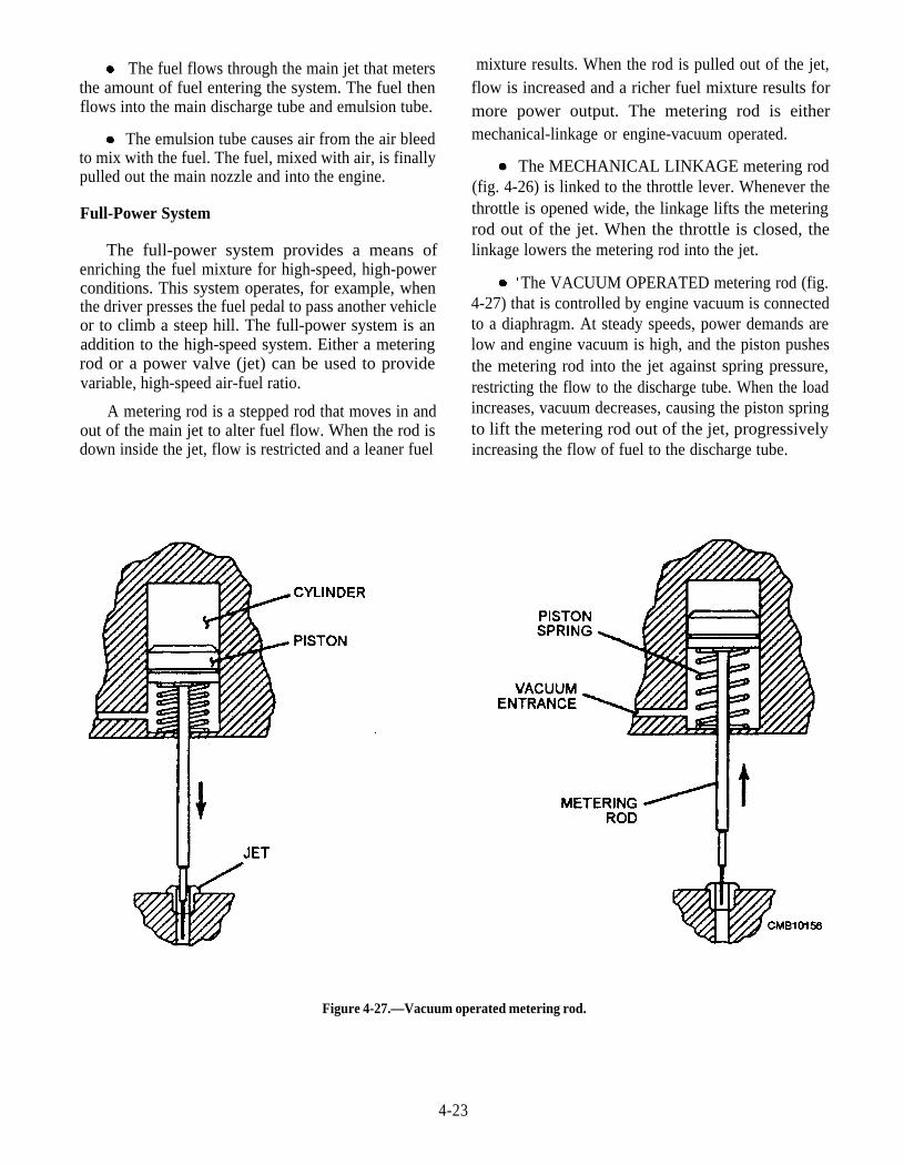
The fuel flows through the main jet that metersthe amount of fuel entering the system. The fuel thenflows into the main discharge tube and emulsion tube.
The emulsion tube causes air from the air bleedto mix with the fuel. The fuel, mixed with air, is finallypulled out the main nozzle and into the engine.
Full-Power System
The full-power system provides a means ofenriching the fuel mixture for high-speed, high-powerconditions. This system operates, for example, whenthe driver presses the fuel pedal to pass another vehicleor to climb a steep hill. The full-power system is anaddition to the high-speed system. Either a meteringrod or a power valve (jet) can be used to providevariable, high-speed air-fuel ratio.
A metering rod is a stepped rod that moves in andout of the main jet to alter fuel flow. When the rod isdown inside the jet, flow is restricted and a leaner fuel
mixture results. When the rod is pulled out of the jet,flow is increased and a richer fuel mixture results formore power output. The metering rod is eithermechanical-linkage or engine-vacuum operated.
The MECHANICAL LINKAGE metering rod(fig. 4-26) is linked to the throttle lever. Whenever thethrottle is opened wide, the linkage lifts the meteringrod out of the jet. When the throttle is closed, thelinkage lowers the metering rod into the jet.
The VACUUM OPERATED metering rod (fig.4-27) that is controlled by engine vacuum is connectedto a diaphragm. At steady speeds, power demands arelow and engine vacuum is high, and the piston pushesthe metering rod into the jet against spring pressure,restricting the flow to the discharge tube. When the loadincreases, vacuum decreases, causing the piston springto lift the metering rod out of the jet, progressivelyincreasing the flow of fuel to the discharge tube.
Figure 4-27.—Vacuum operated metering rod.
4-23
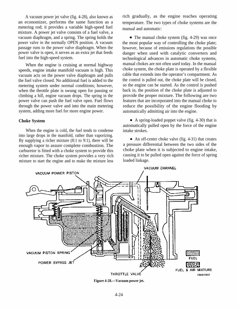
A vacuum power jet valve (fig. 4-28), also known asan economizer, performs the same function as ametering rod; it provides a variable high-speed fuelmixture. A power jet valve consists of a fuel valve, avacuum diaphragm, and a spring. The spring holds thepower valve in the normally OPEN position. A vacuumpassage runs to the power valve diaphragm. When thepower valve is open, it serves as an extra jet that feedsfuel into the high-speed system.
When the engine is cruising at normal highwayspeeds, engine intake manifold vacuum is high. Thisvacuum acts on the power valve diaphragm and pullsthe fuel valve closed. No additional fuel is added to themetering system under normal conditions; however,when the throttle plate is swung open for passing orclimbing a hill, engine vacuum drops. The spring in thepower valve can push the fuel valve open. Fuel flowsthrough the power valve and into the main meteringsystem, adding more fuel for more engine power.
Choke System
When the engine is cold, the fuel tends to condenseinto large drops in the manifold, rather than vaporizing.By supplying a richer mixture (8:1 to 9:1), there will beenough vapor to assure complete combustion. Thecarburetor is fitted with a choke system to provide thisricher mixture. The choke system provides a very richmixture to start the engine and to make the mixture less
rich gradually, as the engine reaches operatingtemperature. The two types of choke systems are themanual and automatic:
The manual choke system (fig. 4-29) was oncethe most popular way of controlling the choke plate;however, because of emissions regulations the possibledanger when used with catalytic converters andtechnological advances in automatic choke systems,manual chokes are not often used today. In the manualchoke system, the choke plate is operated by a flexiblecable that extends into the operator’s compartment. Asthe control is pulled out, the choke plate will be closed,so the engine can be started. As the control is pushedback in, the position of the choke plate is adjusted toprovide the proper mixture. The following are twofeatures that are incorporated into the manual choke toreduce the possibility of the engine flooding byautomatically admitting air into the engine.
A spring-loaded poppet valve (fig. 4-30) that isautomatically pulled open by the force of the engineintake strokes.
An off-center choke valve (fig. 4-31) that createsa pressure differential between the two sides of thechoke plate when it is subjected to engine intake,causing it to be pulled open against the force of springloaded linkage.
Figure 4-28.—Vacuum power jet.
4-24
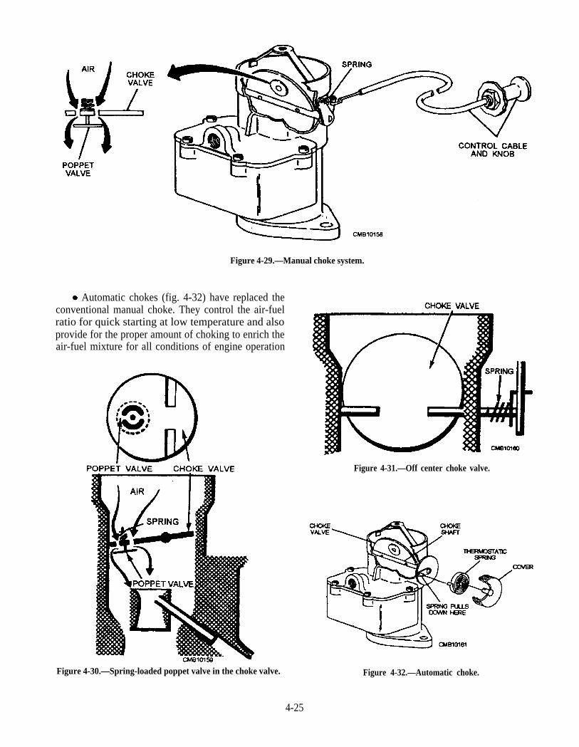
Figure 4-29.—Manual choke system.
Automatic chokes (fig. 4-32) have replaced theconventional manual choke. They control the air-fuelratio for quick starting at low temperature and alsoprovide for the proper amount of choking to enrich theair-fuel mixture for all conditions of engine operation
Figure 4-30.—Spring-loaded poppet valve in the choke valve.
Figure 4-31.—Off center choke valve.
Figure 4-32.—Automatic choke.
4-25

during the warm-up period. An automatic choke systemhas a choke plate (valve), a thermostatic spring, andother parts depending upon choke design.
The choke plate is a butterfly (disc) valve nearthe top of the carburetor air horn. When the choke plateis closed, it blocks normal air flow through thecarburetor.
The thermostatic spring is a bimetal spring(spring made of two dissimilar metals) which may beused to open and close the choke. The two metals have adifferent rate of expansion that make the spring coiltighter when cold and uncoils when heated. Thiscoiling-uncoiling action is used to operate the choke.
The basic operation of the automatic choke systemis as follows:
With the engine cold, the thermostatic springholds the choke closed. When the engine is started, theclosed choke causes high vacuum in the carburetor airhorn. This pulls a large amount of fuel out of the maindischarge tube.
As the engine and thermostatic spring warm, thespring uncoils and opens the choke plate. ‘This actionproduces a leaner mixture. A warm engine will not runproperly if the choke were to remain closed.
Various methods are used to control the warming ofthe choke thermostatic spring. The four methods ofproviding controlled heat to the thermostatic spring areas follows: electricity, engine coolant, well-typeheated, and exhaust manifold.
ELECTRICITY (fig. 4-33) uses an electric coilto heat the thermostatic spring. The heating coil isswitched on with the ignition switch. Some systems usea control unit that prevents power from reaching the
Figure 4-33.—Electric choke.
Figure 4-34.—Engine coolant heated choke.
electric coil until the engine compartment reaches adesired temperature.
ENGINE COOLANT (fig. 4-34) uses a passagein the thermostat housing to circulate engine coolant forheating the thermostatic spring.
WELL-TYPE HEATED (fig. 4-35) mounts thethermostatic spring in the top of the exhaust manifold.As the engine and manifold warms, the thermostaticspring uncoils to open the choke.
The EXHAUST MANIFOLD (fig. 4-36) usesheat from the exhaust manifold to heat the thermostaticspring. The exhaust heat is brought to the chokethrough the means of a heat tube. The heat tube passesthrough the exhaust manifold, so as it takes in fresh airvia the choke stove, it picks up heat from the exhaustwithout sending any actual exhaust fumes to the chokemechanism.
When the choke system is operating during warm-up, the engine must run at a faster idle speed to improvedrivability and prevent flooding. To accomplish this, fit
Figure 4-35.—Well-type exhaust-heated choke.
4-26

Figure 4-36.—Exhaust-manifold heat-tube choke.
the carburetor with a fast idle cam (fig. 4-37) that isoperated by linkage from the choke.
When the choke closes, the fast idle cam swingsaround in front of the fast idle screw. As a result, the fastidle cam and fast idle screw prevent the throttle platefrom closing. Engine idle speed is increased to smoothcold engine operation and prevents stalling. As soon as
the engine warms, the choke opens and the fast idle camis deactivated. When the throttle is opened, the chokelinkage swings away from the fast idle screw and theengine returns to curb idle (normal, hot idle speed).
If for some reason the engine should flood when it iscold, a device is needed to open the choke, so air may beadmitted to correct the condition. This is accomplished
Figure 4-37.—Fast idle cam operation.
4-27
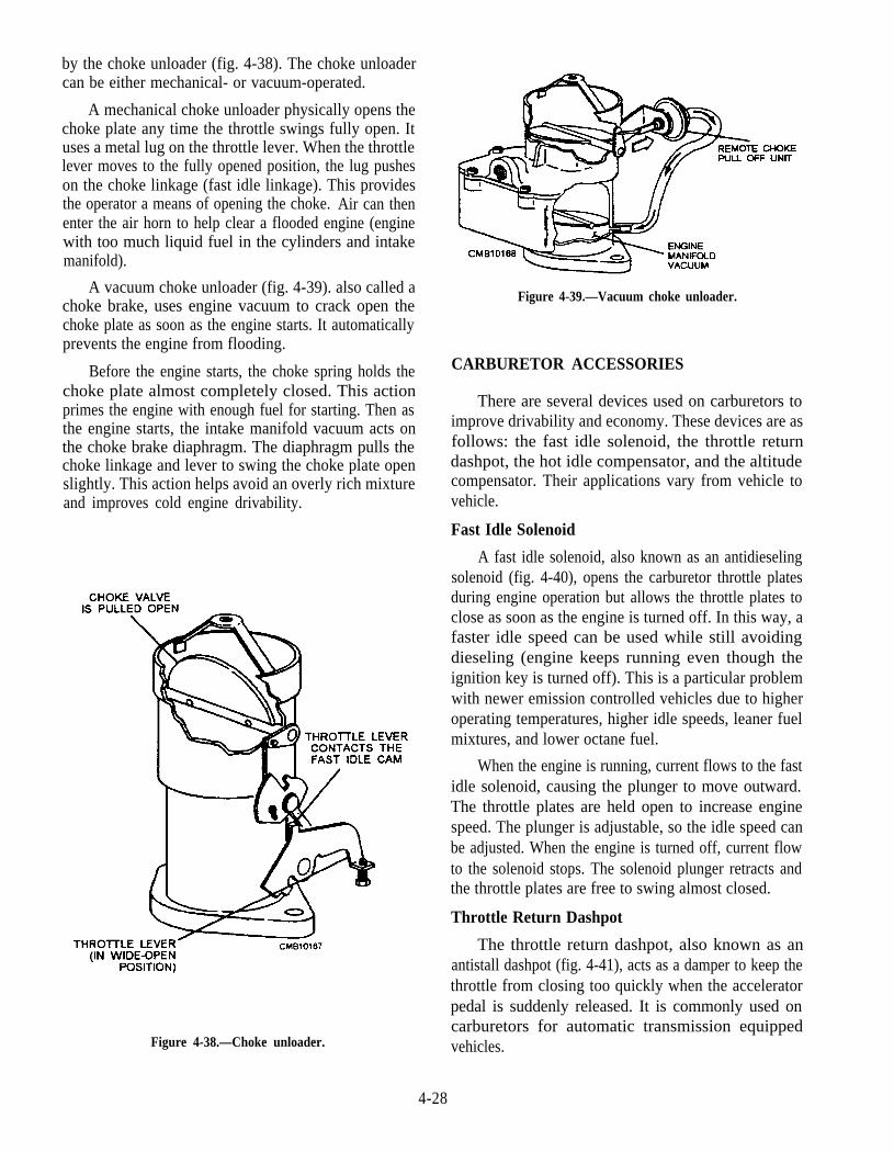
by the choke unloader (fig. 4-38). The choke unloadercan be either mechanical- or vacuum-operated.
A mechanical choke unloader physically opens thechoke plate any time the throttle swings fully open. Ituses a metal lug on the throttle lever. When the throttlelever moves to the fully opened position, the lug pusheson the choke linkage (fast idle linkage). This providesthe operator a means of opening the choke. Air can thenenter the air horn to help clear a flooded engine (enginewith too much liquid fuel in the cylinders and intakemanifold).
A vacuum choke unloader (fig. 4-39). also called achoke brake, uses engine vacuum to crack open thechoke plate as soon as the engine starts. It automaticallyprevents the engine from flooding.
Before the engine starts, the choke spring holds thechoke plate almost completely closed. This actionprimes the engine with enough fuel for starting. Then asthe engine starts, the intake manifold vacuum acts onthe choke brake diaphragm. The diaphragm pulls thechoke linkage and lever to swing the choke plate openslightly. This action helps avoid an overly rich mixtureand improves cold engine drivability.
Figure 4-38.—Choke unloader.
Figure 4-39.—Vacuum choke unloader.
CARBURETOR ACCESSORIES
There are several devices used on carburetors toimprove drivability and economy. These devices are asfollows: the fast idle solenoid, the throttle returndashpot, the hot idle compensator, and the altitudecompensator. Their applications vary from vehicle tovehicle.
Fast Idle Solenoid
A fast idle solenoid, also known as an antidieselingsolenoid (fig. 4-40), opens the carburetor throttle platesduring engine operation but allows the throttle plates toclose as soon as the engine is turned off. In this way, afaster idle speed can be used while still avoidingdieseling (engine keeps running even though theignition key is turned off). This is a particular problemwith newer emission controlled vehicles due to higheroperating temperatures, higher idle speeds, leaner fuelmixtures, and lower octane fuel.
When the engine is running, current flows to the fastidle solenoid, causing the plunger to move outward.The throttle plates are held open to increase enginespeed. The plunger is adjustable, so the idle speed canbe adjusted. When the engine is turned off, current flowto the solenoid stops. The solenoid plunger retracts andthe throttle plates are free to swing almost closed.
Throttle Return Dashpot
The throttle return dashpot, also known as anantistall dashpot (fig. 4-41), acts as a damper to keep thethrottle from closing too quickly when the acceleratorpedal is suddenly released. It is commonly used oncarburetors for automatic transmission equippedvehicles.
4-28

Figure 4-40.—Antidieseling solenoid operation.
Without the throttle return dashpot, the enginecould stall when the engine quickly returned to idle.The drag of the automatic transmission could kill theengine.
The throttle return dashpot works something like ashock absorber. It uses a spring-loaded diaphragmmounted in a sealed housing. A small hole is drilledintothe diaphragm housing to prevent rapid movement ofthe dashpot plunger and diaphragm. Air must bleed outof the hole slowly.
Figure 4-41.—Throttle return dashpot
When the vehicle is traveling down the road(throttle plates open), the spring pushes the dashpotplunger forward. When the engine returns to idle, thethrottle lever strikes the extended dashpot plunger, andair leaks out of the throttle return dashpot, returning theengine slowly to curb idle. This action gives theautomatic transmission enough time to disconnect(torque converter releases) from the engine without theengine stalling.
4-29
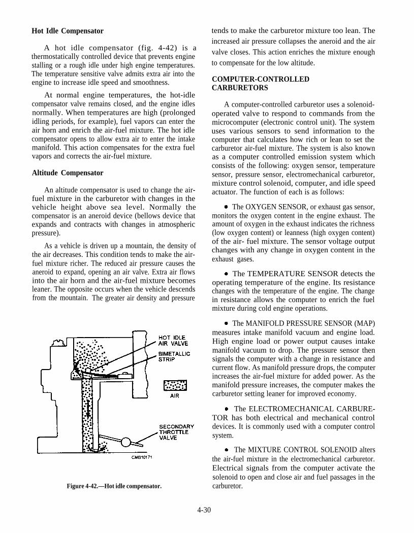
Hot Idle Compensator
A hot idle compensator (fig. 4-42) is athermostatically controlled device that prevents enginestalling or a rough idle under high engine temperatures.The temperature sensitive valve admits extra air into theengine to increase idle speed and smoothness.
At normal engine temperatures, the hot-idlecompensator valve remains closed, and the engine idlesnormally. When temperatures are high (prolongedidling periods, for example), fuel vapors can enter theair horn and enrich the air-fuel mixture. The hot idlecompensator opens to allow extra air to enter the intakemanifold. This action compensates for the extra fuelvapors and corrects the air-fuel mixture.
Altitude Compensator
An altitude compensator is used to change the air-fuel mixture in the carburetor with changes in thevehicle height above sea level. Normally thecompensator is an aneroid device (bellows device thatexpands and contracts with changes in atmosphericpressure).
As a vehicle is driven up a mountain, the density ofthe air decreases. This condition tends to make the air-fuel mixture richer. The reduced air pressure causes theaneroid to expand, opening an air valve. Extra air flowsinto the air horn and the air-fuel mixture becomesleaner. The opposite occurs when the vehicle descendsfrom the mountain. The greater air density and pressure
Figure 4-42.—Hot idle compensator.
tends to make the carburetor mixture too lean. Theincreased air pressure collapses the aneroid and the airvalve closes. This action enriches the mixture enoughto compensate for the low altitude.
COMPUTER-CONTROLLEDCARBURETORS
A computer-controlled carburetor uses a solenoid-operated valve to respond to commands from themicrocomputer (electronic control unit). The systemuses various sensors to send information to thecomputer that calculates how rich or lean to set thecarburetor air-fuel mixture. The system is also knownas a computer controlled emission system whichconsists of the following: oxygen sensor, temperaturesensor, pressure sensor, electromechanical carburetor,mixture control solenoid, computer, and idle speedactuator. The function of each is as follows:
4-30
The OXYGEN SENSOR, or exhaust gas sensor,monitors the oxygen content in the engine exhaust. Theamount of oxygen in the exhaust indicates the richness(low oxygen content) or leanness (high oxygen content)of the air- fuel mixture. The sensor voltage outputchanges with any change in oxygen content in theexhaust gases.
The TEMPERATURE SENSOR detects theoperating temperature of the engine. Its resistancechanges with the temperature of the engine. The changein resistance allows the computer to enrich the fuelmixture during cold engine operations.
The MANIFOLD PRESSURE SENSOR (MAP)measures intake manifold vacuum and engine load.High engine load or power output causes intakemanifold vacuum to drop. The pressure sensor thensignals the computer with a change in resistance andcurrent flow. As manifold pressure drops, the computerincreases the air-fuel mixture for added power. As themanifold pressure increases, the computer makes thecarburetor setting leaner for improved economy.
The ELECTROMECHANICAL CARBURE-TOR has both electrical and mechanical controldevices. It is commonly used with a computer controlsystem.
The MIXTURE CONTROL SOLENOID altersthe air-fuel mixture in the electromechanical carburetor.Electrical signals from the computer activate thesolenoid to open and close air and fuel passages in thecarburetor.
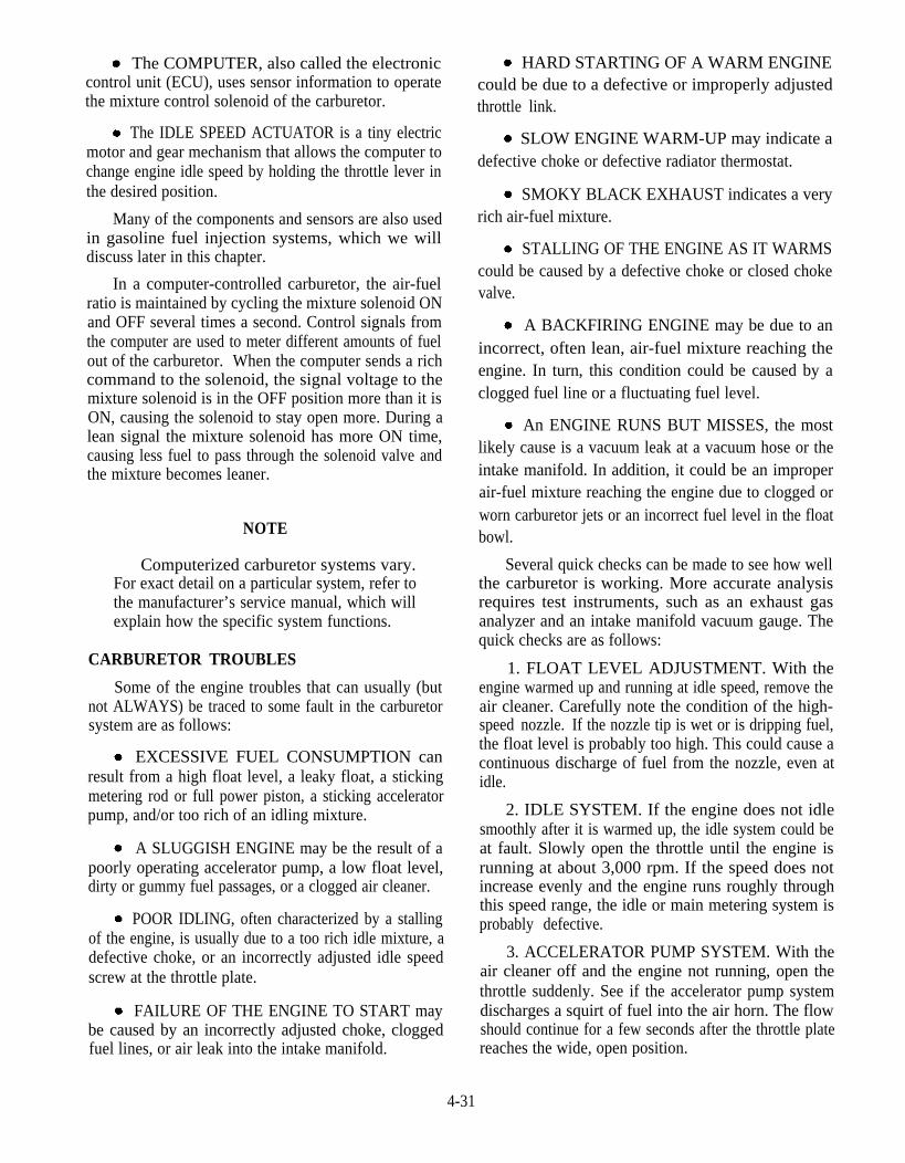
The COMPUTER, also called the electroniccontrol unit (ECU), uses sensor information to operatethe mixture control solenoid of the carburetor.
The IDLE SPEED ACTUATOR is a tiny electricmotor and gear mechanism that allows the computer tochange engine idle speed by holding the throttle lever inthe desired position.
Many of the components and sensors are also usedin gasoline fuel injection systems, which we willdiscuss later in this chapter.
In a computer-controlled carburetor, the air-fuelratio is maintained by cycling the mixture solenoid ONand OFF several times a second. Control signals fromthe computer are used to meter different amounts of fuelout of the carburetor. When the computer sends a richcommand to the solenoid, the signal voltage to themixture solenoid is in the OFF position more than it isON, causing the solenoid to stay open more. During alean signal the mixture solenoid has more ON time,causing less fuel to pass through the solenoid valve andthe mixture becomes leaner.
NOTE
Computerized carburetor systems vary.For exact detail on a particular system, refer tothe manufacturer’s service manual, which willexplain how the specific system functions.
CARBURETOR TROUBLES
Some of the engine troubles that can usually (butnot ALWAYS) be traced to some fault in the carburetorsystem are as follows:
EXCESSIVE FUEL CONSUMPTION canresult from a high float level, a leaky float, a stickingmetering rod or full power piston, a sticking acceleratorpump, and/or too rich of an idling mixture.
A SLUGGISH ENGINE may be the result of apoorly operating accelerator pump, a low float level,dirty or gummy fuel passages, or a clogged air cleaner.
POOR IDLING, often characterized by a stallingof the engine, is usually due to a too rich idle mixture, adefective choke, or an incorrectly adjusted idle speedscrew at the throttle plate.
FAILURE OF THE ENGINE TO START maybe caused by an incorrectly adjusted choke, cloggedfuel lines, or air leak into the intake manifold.
HARD STARTING OF A WARM ENGINEcould be due to a defective or improperly adjustedthrottle link.
SLOW ENGINE WARM-UP may indicate adefective choke or defective radiator thermostat.
SMOKY BLACK EXHAUST indicates a veryrich air-fuel mixture.
STALLING OF THE ENGINE AS IT WARMScould be caused by a defective choke or closed chokevalve.
A BACKFIRING ENGINE may be due to anincorrect, often lean, air-fuel mixture reaching theengine. In turn, this condition could be caused by aclogged fuel line or a fluctuating fuel level.
An ENGINE RUNS BUT MISSES, the mostlikely cause is a vacuum leak at a vacuum hose or theintake manifold. In addition, it could be an improperair-fuel mixture reaching the engine due to clogged orworn carburetor jets or an incorrect fuel level in the floatbowl.
Several quick checks can be made to see how wellthe carburetor is working. More accurate analysisrequires test instruments, such as an exhaust gasanalyzer and an intake manifold vacuum gauge. Thequick checks are as follows:
1. FLOAT LEVEL ADJUSTMENT. With theengine warmed up and running at idle speed, remove theair cleaner. Carefully note the condition of the high-speed nozzle. If the nozzle tip is wet or is dripping fuel,the float level is probably too high. This could cause acontinuous discharge of fuel from the nozzle, even atidle.
2. IDLE SYSTEM. If the engine does not idlesmoothly after it is warmed up, the idle system could beat fault. Slowly open the throttle until the engine isrunning at about 3,000 rpm. If the speed does notincrease evenly and the engine runs roughly throughthis speed range, the idle or main metering system isprobably defective.
3. ACCELERATOR PUMP SYSTEM. With theair cleaner off and the engine not running, open thethrottle suddenly. See if the accelerator pump systemdischarges a squirt of fuel into the air horn. The flowshould continue for a few seconds after the throttle platereaches the wide, open position.
4-31

4. MAIN METERING SYSTEM. With the enginewarmed up and running at 2,000 rpm, slowly cover partof the air horn with a piece of stiff cardboard Theengine should speed up slightly, since this action causesa normal operating main metering system to dischargemore fuel.
WARNING
Do NOT use your hand to cover the air hornwhen performing this test.
Q5.
Q6.
Q7.
Q8.
Name the seven basic carburetor systems?
What system maintains a steady working supplyof fuel to a constant level in the carburetor?
What device acts as a damper to keep the throttlefrom closing too quickly when the acceleratorpedal is suddenly released?
What sensor in a computerized carburetorsystem measures intake vacuum and engineload?
GASOLINE FUEL INJECTIONSYSTEMS
LEARNING OBJECTIVE: Identify anddescribe the different gasoline fuel injectionsystems.
A modern gasoline injection system uses pressurefrom an electric fuel pump to spray fuel into the engineintake manifold. Like a carburetor, it must provide theengine with the correct air-fuel mixture for specificoperating conditions. Unlike a carburetor, however,PRESSURE, not engine vacuum, is used to feed fuelinto the engine. This makes the gasoline injectionsystem very efficient.
A gasoline injection system has several possibleadvantages over a carburetor type of fuel system. Someadvantages are as follows:
Improved atomization. Fuel is forced into theintake manifold under pressure that helps break fueldroplets into a fine mist.
Better fuel distribution. Equal flow of fuelvapors into each cylinder.
Smoother idle. Lean fuel mixture can be usedwithout rough idle because of better fuel distributionand low-speed atomization.
Lower emissions. Lean efficient air-fuel mixturereduces exhaust pollution.
Better cold weather drivability. Injectionprovides better control of mixture enrichment than acarburetor.
Increased engine power. Precise metering offuel to each cylinder and increased air flow can result inmore horsepower output.
Fewer parts. Simpler, late model, electronic fuelinjection system have fewer parts than moderncomputer-controlled carburetors.
There are many types of gasoline injection systems.Before studying the most common ones, you shouldhave a basic knowledge of the different classifications.Systems are classified either single- or multi-pointinjection and indirect or direct injection.
The point or location of fuel injection is one way toclassify a gasoline injection system. A single-pointinjection system, also call throttle body injection (TBI),has the injector nozzles in a throttle body assembly ontop of the engine. Fuel is sprayed into the top center ofthe intake manifold
A multi-point injection system, also called portinjection, has an injector in the port (air-fuel passage)going to each cylinder. Gasoline is sprayed into eachintake port and toward each intake valve. Thereby, theterm multi-point (more than one location) fuel injectionis used.
An indirect injection system sprays fuel into theengine intake manifold. Most gasoline injectionsystems are of this type. Direct injection forces fuel intothe engine combustion chambers. Diesel injectionsystems are direct type.
There are three basic configurations of gasoline fuelinjection—timed, continuous, and throttle body.
TIMED FUEL INJECTIONSYSTEM
Timed fuel injection systems for gasoline enginesinject a measured amount of fuel in timed bursts that aresynchronized to the intake strokes of the engine. ‘limedinjection is the most precise form of fuel injection but isalso the most complex. There are two basic forms oftimed fuel injection-mechanical and electronic.
The basic operation of a mechanical-timedinjection system (fig. 4-43) is as follows:
4-32
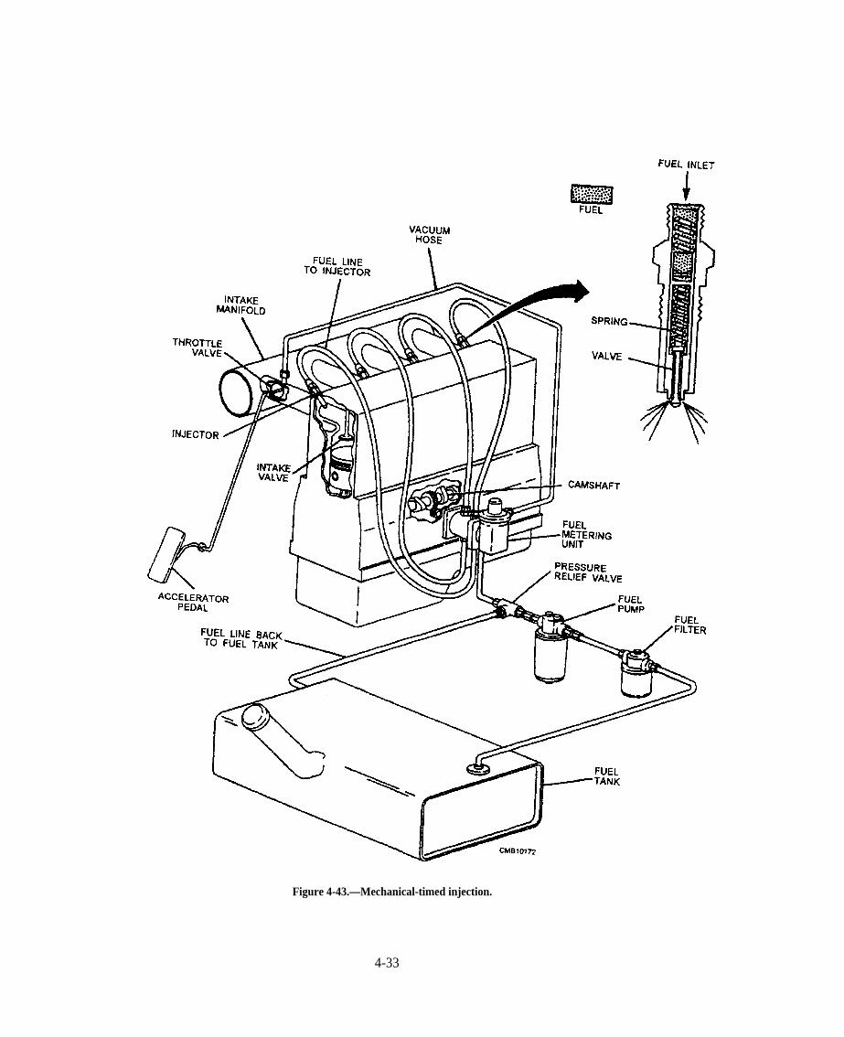
Figure 4-43.—Mechanical-timed injection.
4-33
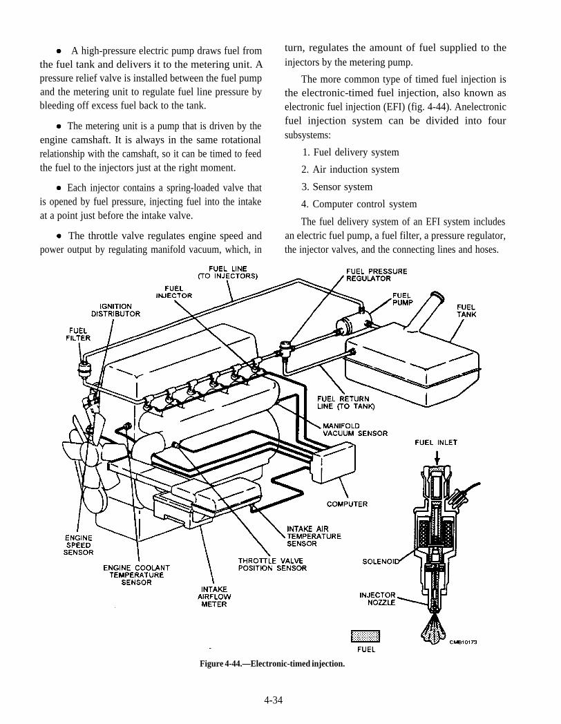
A high-pressure electric pump draws fuel fromthe fuel tank and delivers it to the metering unit. Apressure relief valve is installed between the fuel pumpand the metering unit to regulate fuel line pressure bybleeding off excess fuel back to the tank.
The metering unit is a pump that is driven by theengine camshaft. It is always in the same rotationalrelationship with the camshaft, so it can be timed to feedthe fuel to the injectors just at the right moment.
Each injector contains a spring-loaded valve thatis opened by fuel pressure, injecting fuel into the intakeat a point just before the intake valve.
The throttle valve regulates engine speed andpower output by regulating manifold vacuum, which, in
turn, regulates the amount of fuel supplied to theinjectors by the metering pump.
The more common type of timed fuel injection isthe electronic-timed fuel injection, also known aselectronic fuel injection (EFI) (fig. 4-44). Anelectronicfuel injection system can be divided into foursubsystems:
1. Fuel delivery system
2. Air induction system
3. Sensor system
4. Computer control system
The fuel delivery system of an EFI system includesan electric fuel pump, a fuel filter, a pressure regulator,the injector valves, and the connecting lines and hoses.
Figure 4-44.—Electronic-timed injection.
4-34
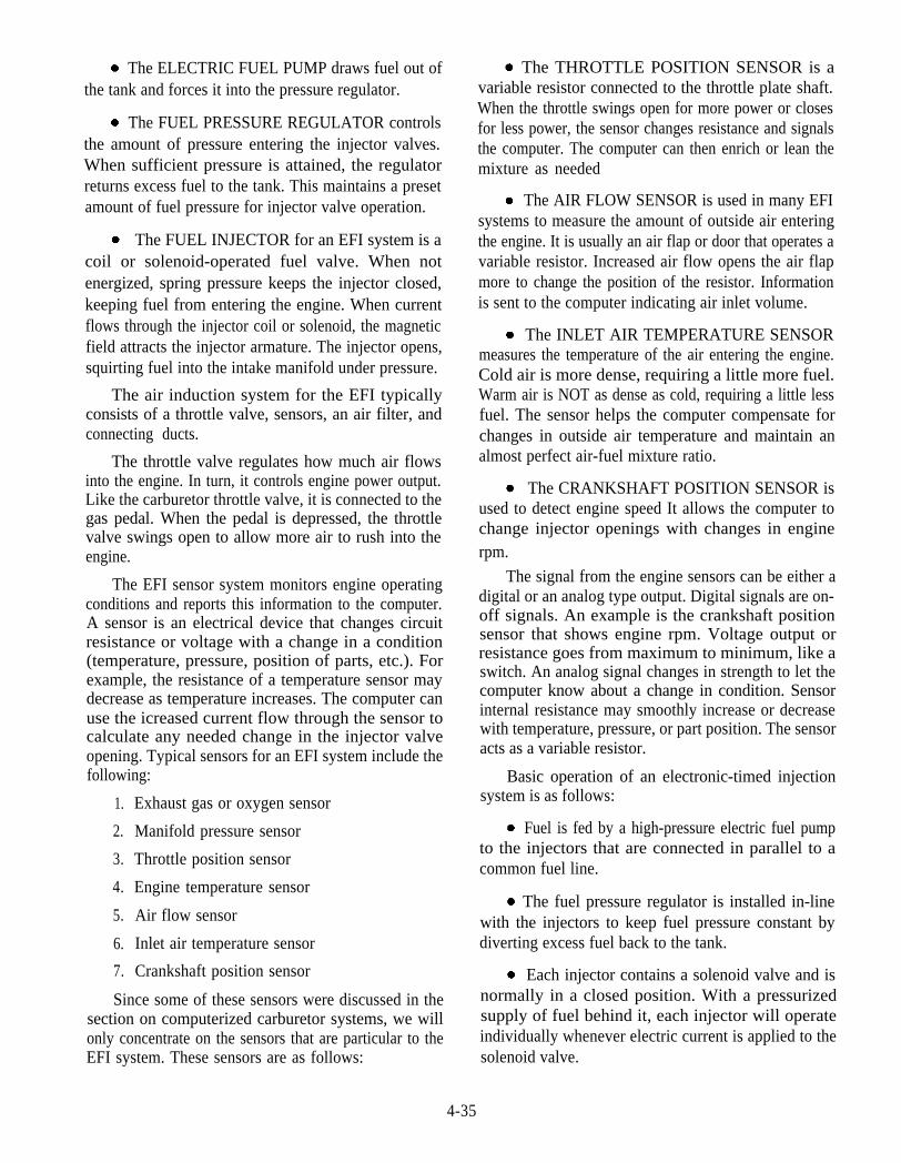
The ELECTRIC FUEL PUMP draws fuel out ofthe tank and forces it into the pressure regulator.
The FUEL PRESSURE REGULATOR controlsthe amount of pressure entering the injector valves.When sufficient pressure is attained, the regulatorreturns excess fuel to the tank. This maintains a presetamount of fuel pressure for injector valve operation.
The FUEL INJECTOR for an EFI system is acoil or solenoid-operated fuel valve. When notenergized, spring pressure keeps the injector closed,keeping fuel from entering the engine. When currentflows through the injector coil or solenoid, the magneticfield attracts the injector armature. The injector opens,squirting fuel into the intake manifold under pressure.
The air induction system for the EFI typicallyconsists of a throttle valve, sensors, an air filter, andconnecting ducts.
The throttle valve regulates how much air flowsinto the engine. In turn, it controls engine power output.Like the carburetor throttle valve, it is connected to thegas pedal. When the pedal is depressed, the throttlevalve swings open to allow more air to rush into theengine.
The EFI sensor system monitors engine operatingconditions and reports this information to the computer.A sensor is an electrical device that changes circuitresistance or voltage with a change in a condition(temperature, pressure, position of parts, etc.). Forexample, the resistance of a temperature sensor maydecrease as temperature increases. The computer canuse the icreased current flow through the sensor tocalculate any needed change in the injector valveopening. Typical sensors for an EFI system include thefollowing:
1. Exhaust gas or oxygen sensor
2. Manifold pressure sensor
3. Throttle position sensor
4. Engine temperature sensor
5. Air flow sensor
6. Inlet air temperature sensor
7. Crankshaft position sensor
Since some of these sensors were discussed in thesection on computerized carburetor systems, we willonly concentrate on the sensors that are particular to theEFI system. These sensors are as follows:
The THROTTLE POSITION SENSOR is avariable resistor connected to the throttle plate shaft.When the throttle swings open for more power or closesfor less power, the sensor changes resistance and signalsthe computer. The computer can then enrich or lean themixture as needed
The AIR FLOW SENSOR is used in many EFIsystems to measure the amount of outside air enteringthe engine. It is usually an air flap or door that operates avariable resistor. Increased air flow opens the air flapmore to change the position of the resistor. Informationis sent to the computer indicating air inlet volume.
The INLET AIR TEMPERATURE SENSORmeasures the temperature of the air entering the engine.Cold air is more dense, requiring a little more fuel.Warm air is NOT as dense as cold, requiring a little lessfuel. The sensor helps the computer compensate forchanges in outside air temperature and maintain analmost perfect air-fuel mixture ratio.
The CRANKSHAFT POSITION SENSOR isused to detect engine speed It allows the computer tochange injector openings with changes in enginerpm.
The signal from the engine sensors can be either adigital or an analog type output. Digital signals are on-off signals. An example is the crankshaft positionsensor that shows engine rpm. Voltage output orresistance goes from maximum to minimum, like aswitch. An analog signal changes in strength to let thecomputer know about a change in condition. Sensorinternal resistance may smoothly increase or decreasewith temperature, pressure, or part position. The sensoracts as a variable resistor.
Basic operation of an electronic-timed injectionsystem is as follows:
Fuel is fed by a high-pressure electric fuel pumpto the injectors that are connected in parallel to acommon fuel line.
The fuel pressure regulator is installed in-linewith the injectors to keep fuel pressure constant bydiverting excess fuel back to the tank.
Each injector contains a solenoid valve and isnormally in a closed position. With a pressurizedsupply of fuel behind it, each injector will operateindividually whenever electric current is applied to thesolenoid valve.
4-35
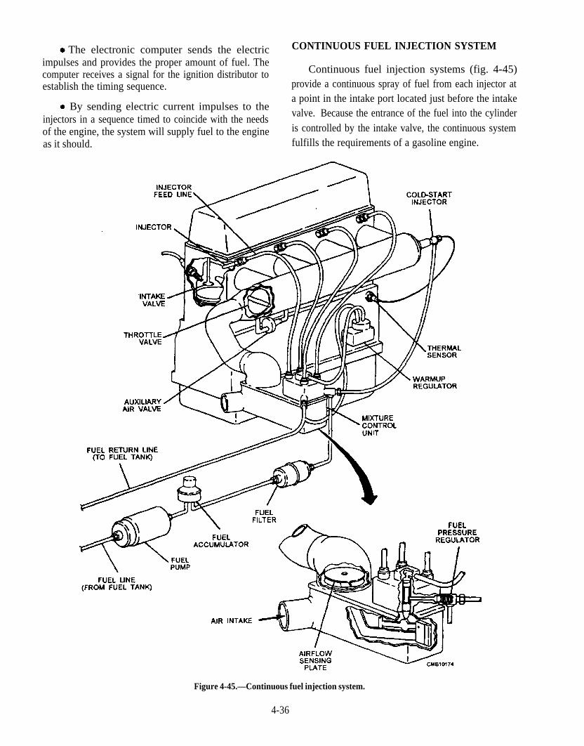
The electronic computer sends the electricimpulses and provides the proper amount of fuel. Thecomputer receives a signal for the ignition distributor toestablish the timing sequence.
CONTINUOUS FUEL INJECTION SYSTEM
Continuous fuel injection systems (fig. 4-45)provide a continuous spray of fuel from each injector at
By sending electric current impulses to theinjectors in a sequence timed to coincide with the needsof the engine, the system will supply fuel to the engineas it should.
a point in the intake port located just before the intakevalve. Because the entrance of the fuel into the cylinderis controlled by the intake valve, the continuous systemfulfills the requirements of a gasoline engine.
Figure 4-45.—Continuous fuel injection system.
4-36
Basic operation of a continuous fuel injection is asfollows:
Fuel is fed to the system by an electric fuel pumpthat delivers fuel to the mixture control unit. A fuelpressure regulator maintains fuel line pressure andsends excess fuel back to the tank.
The mixture control unit regulates the amount offuel that is sent to the injectors based on the amount ofair flow through the intake and the engine temperature.The unit is operated by the air flow sensing plate andwarm-up regulator.
The accelerator pedal regulates the rate of airflow through the intake by opening and closing thethrottle valve.
A cold-start injector is installed in the intake toprovide a richer mixture during engine start-up andwarm-up. It is actuated by electric current from thethermal sensor any time the temperature of the coolantis below a certain level.
The injector for a continuous fuel injection systemis a simple spring-loaded valve. It injects fuel all thetime the engine is running. A spring holds the valve in anormally closed position with the engine OFF. This
action keeps fuel from dripping into the engine. Whenthe engine STARTS, fuel pressure builds and pushes theinjector valve open. A steady stream of gasoline thensprays toward each intake valve. The fuel is pulled intothe engine when the intake valves open
THROTTLE BODY INJECTION SYSTEM
The throttle body injection (TBI) system (fig. 4-46)uses one or two injector valves mounted in a throttlebody assembly. The injectors spray fuel into the top ofthe throttle body air horn The TBI fuel spray mixeswith the air flowing through the air horn. The mixture isthen pulled into the engine by intake manifold vacuum.The throttle body injection assembly typically consistsof the following: throttle body housing, fuel injectors,fuel pressure regulator, throttle positioner, throttleposition sensor, and throttle plates.
The THROTTLE BODY housing, like acarburetor body, bolts to the pad on the intake manifold.It houses the metal castings that hold the injectors, thefuel pressure regulator, and the throttle plates. Thethrottle plates are located in the lower section of thebody. A linkage or cable connects the throttle plateswith the accelerator pedal. An inlet fuel line and outletreturn line connects to the fittings on the body.
Figure 4-46.—Throttle body injection.
4-37

The THROTTLE BODY INJECTOR consists ofan electric solenoid coil, armature or plunger, ball orneedle valve and seat, and injector spring. Wires fromthe computer connect to terminals on the injectors.When the computer energizes the injectors, a magneticfield is produced in the injector coil. The magnetic fieldpulls the plunger and valve up to open the injector. Fuelcan then squirt through the injector nozzle and into theengine.
The THROTTLE BODY PRESSURE REG-ULATOR consists of a fuel valve, a diaphragm, and aspring. When fuel pressure is low, the spring holds thefuel valve closed, causing pressure to build as fuel flowsinto the regulator from the fuel pump. When a presetpressure is reached, pressure acts on the diaphragm.The diaphragm compresses the spring and opens thefuel valve. Fuel can then flow back to the fuel tank,limiting the maximum fuel pressure at the injectors.
The THROTTLE POSITIONER is used onthrottle body assemblies to control engine idle speed.The computer actuates the positioner to open or closethe throttle plates. In this way, the computer canmaintain a precise idle speed with changes in enginetemperature, load, and other conditions.
Although throttle body injection does not providethe precise fuel distribution of the direct port injection,it is much cheaper to produce and provide a much higherdegree of precision fuel metering than a carburetor.
Q9. What type of fuel injection system is the mostprecise but is also the most complex?
Q10. In an electronic fuel injection system, whatsensor is used to detect engine speed?
Q11. On a throttle body injection system, what deviceis used to control engine idle speed?
EXHAUST AND EMISSION CONTROLSYSTEMS
LEARNING OBJECTIVE: Identifycomponents of the exhaust and emissioncontrol systems. Describe the operation of theexhaust and emission control systems.
Over the past several years, exhaust and emissioncontrol has greatly increased because of stringentantipollution laws and EPA guidelines. This has madethe exhaust and emission control systems of vehiclesinvaluable and a vital part of today’s vehicles.
4-38
The waste products of combustion are carried awayfrom the engine to the rear of the vehicle by the exhaustsystem where they are expelled to the atmosphere. Theexhaust system also serves to dampen engine noise.The parts of a typical exhaust system include thefollowing: exhaust manifold, header pipe, catalyticconverter, intermediate pipe, muffler, tailpipe, hangers,heat shields, and muffler clamps.
The control of exhaust emissions is a difficult job.The ideal situation would be to have the fuel combinecompletely with the oxygen from the intake air. Thecarbon would then combine with the oxygen to formcarbon dioxide (CO2); the hydrogen would combine toform water (H2O); and the nitrogen present in the intakewould stand alone. The only other product present inthe exhaust would be oxygen from the intake air thatwas not used in the burning of the fuel. In a real lifesituation, however, this is not what happens. The fuelnever combines completely with the oxygen, andundesirable exhaust emissions are created as a result.
The most dangerous of the emissions is CARBONMONOXIDE (CO) which is a poisonous gas that iscolorless and odorless. CO is formed as a result ofinsufficient oxygen in the combustion mixture andcombustion chamber temperatures that are too low.Other exhaust emissions that are considered majorpollutants are as follows:
HYDROCARBONS (HC) are unburned fuel.They are particulate (solid) in form, and, like carbonmonoxide, they are manufactured by insufficientoxygen in the combustion mixture and combustionchamber temperatures that are too low. Hydrocarbonsare harmful to all living things. In any urban area wherevehicular traffic is heavy, hydrocarbons in heavyconcentrations react with the sunlight to produce abrown fog, known as photochemical smog.
OXIDES OF NITROGEN (NOX) are formedwhen nitrogen and oxygen in the intake air combinewhen subjected to high temperatures of combustion.Oxides of nitrogen are harmful to all living things.
The temperatures of the combustion chamberwould have to be raised to a point that would meltpistons and valves to eliminate carbon monoxide andcarbon dioxide emissions. This is compounded with thefact that oxides of nitrogen emissions go up with anyincrease in the combustion chamber temperature.Knowing these facts, it can be seen that emissioncontrol devices are necessary.
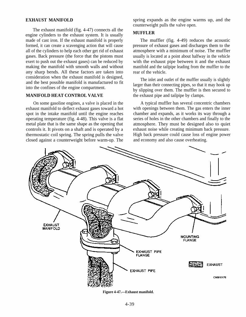
EXHAUST MANIFOLD
The exhaust manifold (fig. 4-47) connects all theengine cylinders to the exhaust system. It is usuallymade of cast iron. If the exhaust manifold is properlyformed, it can create a scavenging action that will causeall of the cylinders to help each other get rid of exhaustgases. Back pressure (the force that the pistons mustexert to push out the exhaust gases) can be reduced bymaking the manifold with smooth walls and withoutany sharp bends. All these factors are taken intoconsideration when the exhaust manifold is designed,and the best possible manifold is manufactured to fitinto the confines of the engine compartment.
MANIFOLD HEAT CONTROL VALVE
On some gasoline engines, a valve is placed in theexhaust manifold to deflect exhaust gases toward a hotspot in the intake manifold until the engine reachesoperating temperature (fig. 4-48). This valve is a flatmetal plate that is the same shape as the opening thatcontrols it. It pivots on a shaft and is operated by athermostatic coil spring. The spring pulls the valveclosed against a counterweight before warm-up. The
spring expands as the engine warms up, and thecounterweight pulls the valve open.
MUFFLER
The muffler (fig. 4-49) reduces the acousticpressure of exhaust gases and discharges them to theatmosphere with a minimum of noise. The mufflerusually is located at a point about halfway in the vehiclewith the exhaust pipe between it and the exhaustmanifold and the tailpipe leading from the muffler to therear of the vehicle.
The inlet and outlet of the muffler usually is slightlylarger than their connecting pipes, so that it may hook upby slipping over them. The muffler is then secured tothe exhaust pipe and tailpipe by clamps.
A typical muffler has several concentric chamberswith openings between them. The gas enters the innerchamber and expands, as it works its way through aseries of holes in the other chambers and finally to theatmosphere. They must be designed also to quietexhaust noise while creating minimum back pressure.High back pressure could cause loss of engine powerand economy and also cause overheating.
Figure 4-47.—Exhaust manifold.
4-39
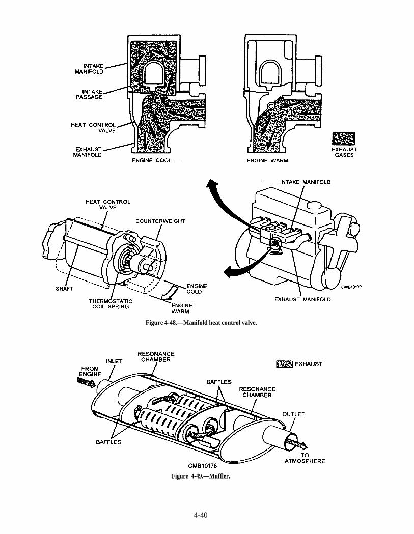
Figure 4-48.—Manifold heat control valve.
Figure 4-49.—Muffler.
4-40
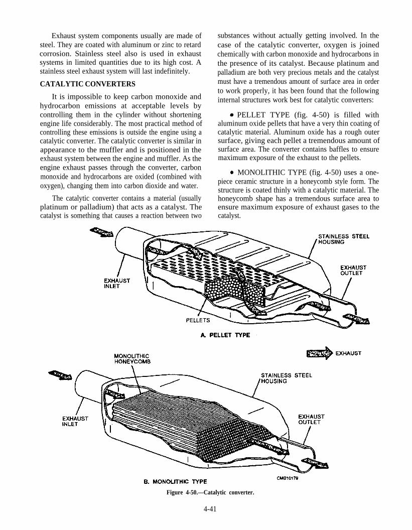
Exhaust system components usually are made ofsteel. They are coated with aluminum or zinc to retardcorrosion. Stainless steel also is used in exhaustsystems in limited quantities due to its high cost. Astainless steel exhaust system will last indefinitely.
CATALYTIC CONVERTERS
It is impossible to keep carbon monoxide andhydrocarbon emissions at acceptable levels bycontrolling them in the cylinder without shorteningengine life considerably. The most practical method ofcontrolling these emissions is outside the engine using acatalytic converter. The catalytic converter is similar inappearance to the muffler and is positioned in theexhaust system between the engine and muffler. As theengine exhaust passes through the converter, carbonmonoxide and hydrocarbons are oxided (combined withoxygen), changing them into carbon dioxide and water.
The catalytic converter contains a material (usuallyplatinum or palladium) that acts as a catalyst. Thecatalyst is something that causes a reaction between two
substances without actually getting involved. In thecase of the catalytic converter, oxygen is joinedchemically with carbon monoxide and hydrocarbons inthe presence of its catalyst. Because platinum andpalladium are both very precious metals and the catalystmust have a tremendous amount of surface area in orderto work properly, it has been found that the followinginternal structures work best for catalytic converters:
PELLET TYPE (fig. 4-50) is filled withaluminum oxide pellets that have a very thin coating ofcatalytic material. Aluminum oxide has a rough outersurface, giving each pellet a tremendous amount ofsurface area. The converter contains baffles to ensuremaximum exposure of the exhaust to the pellets.
MONOLITHIC TYPE (fig. 4-50) uses a one-piece ceramic structure in a honeycomb style form. Thestructure is coated thinly with a catalytic material. Thehoneycomb shape has a tremendous surface area toensure maximum exposure of exhaust gases to thecatalyst.
Figure 4-50.—Catalytic converter.
4-41

An adequate amount of oxygen must be present inthe exhaust system for the catalytic converter tooperate; therefore, a supporting system, such as an airinjection system, usually is placed on catalyticconverter equipped engines to dilute the exhaust streamwith fresh air.
AIR INJECTION SYSTEM
An air injection system (fig. 4-51) forces fresh airinto the exhaust ports of the engine to reduce HC andCO emissions. The exhaust gases leaving an engine cancontain unburned and partially burned fuel. Oxygenfrom the air injection system causes this fuel to continueto burn. The major parts of the system are the air pump,the diverter valve, the air distribution manifold, and theair check valve.
The AIR PUMP is belt-driven and forces air atlow pressure into the system. A hose is connected to theoutput of the diverter valve.
The DIVERTER VALVE keeps air from enteringthe exhaust system during deceleration. This preventsbackfiring in the exhaust system. Also, the divertervalve limits maximum system air pressure whenneeded, releasing excessive pressure through a silenceror a muffler.
AIR DISTRIBUTION MANIFOLD directs astream of fresh air toward each engine exhaust valve.Fittings on the air distribution manifold screw into athreaded hole in the exhaust manifold or cylinderhead.
AIR CHECK VALVE is usually located in theline between the diverter valve and the air distributionmanifold. It keeps exhaust gases from entering the airinjection system.
Basic operation of the air injection system is asfollows:
When the engine is running, the spinning vanesof the air pump force air into the diverter valve. If notdecelerating, the air is forced through the diverter valve,the check valve, the air injection manifold, and into theengine. The fresh air blows on the exhaust valves.
During periods of deceleration, the divertervalve blocks air flow into the engine exhaust manifold.This prevents a possible backfire that could damage theexhaust system of the vehicle. When needed, thediverter valve will release excess pressure in thesystem.
POSITIVE CRANKCASE VENTILATION(PCV) SYSTEM
The positive crankcase ventilation system usesmanifold vacuum to purge the crankcase blow-byfumes. The fumes are then aspirated back into theengine where they are reburned.
A hose is tapped into the crankcase at a point that iswell above the engine oil level. The other end of thehose is tapped into the intake manifold or the base of thecarburetor.
NOTE
If the hose is tapped into the carburetorbase, it will be in a location that is between thethrottle valves and the intake manifold so that itwill receive manifold vacuum.
An inlet breather is installed on the crankcase in alocation that is well above the level of the engine oil.The inlet breather also is located strategically to ensurecomplete purging of the crankcase fresh air. The areasof the crankcase where the vacuum hose and inletbreather are tapped have baffles to keep motor oil fromleaving the crankcase.
A flow control valve is installed in the line thatconnects the crankcase to the manifold. It is called apositive crankcase ventilation (PCV) valve (fig. 4-52)and serves to avoid the air-fuel mixture by doing thefollowing:
Any periods of large throttle opening will beaccompanied by heavy engine loads. Crankcase blow-by will be at its maximum during heavy engine loads.The PCV valve will react to the small amount ofmanifold vacuum that also is present during heavyengine loading by opening fully through the force of itscontrol valve spring. In this way, the system providesmaximum effectiveness during maximum blow-byperiods.
Any period of small throttle opening will beaccompanied by small engine loads, high manifoldvacuum, and a minimum amount of crankcase blow-by.During these periods, the high manifold vacuum willpull the PCV valve to its position of minimum opening.This is important to prevent an excessively lean air-fuelmixture.
In the event of engine backfire (flame travelingback through the intake manifold), the reverse pressurewill push the rear shoulder of the control valve against
4-42
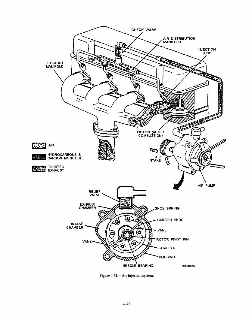
Figure 4-51.—Air injection system.
4-43
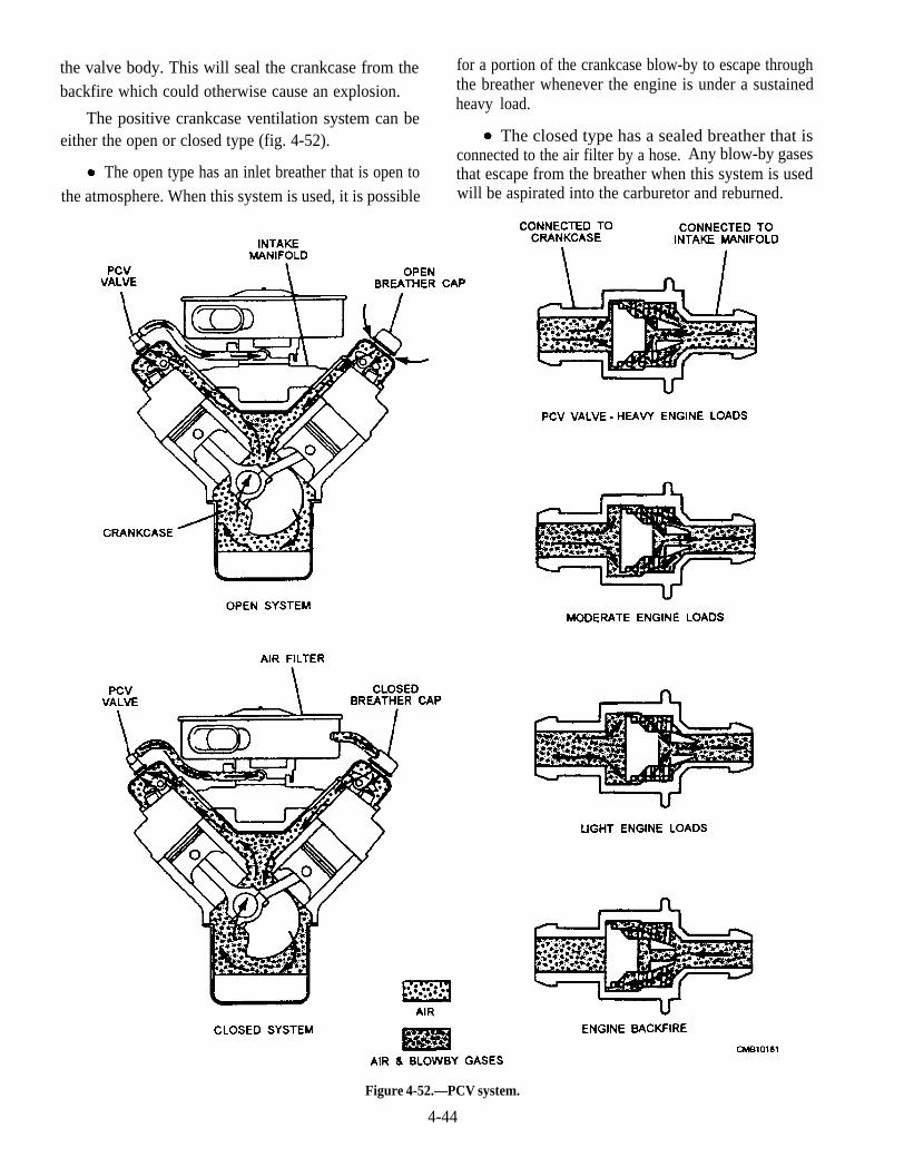
the valve body. This will seal the crankcase from thebackfire which could otherwise cause an explosion.
The positive crankcase ventilation system can beeither the open or closed type (fig. 4-52).
The open type has an inlet breather that is open tothe atmosphere. When this system is used, it is possible
for a portion of the crankcase blow-by to escape throughthe breather whenever the engine is under a sustainedheavy load.
The closed type has a sealed breather that isconnected to the air filter by a hose. Any blow-by gasesthat escape from the breather when this system is usedwill be aspirated into the carburetor and reburned.
Figure 4-52.—PCV system.
4-44
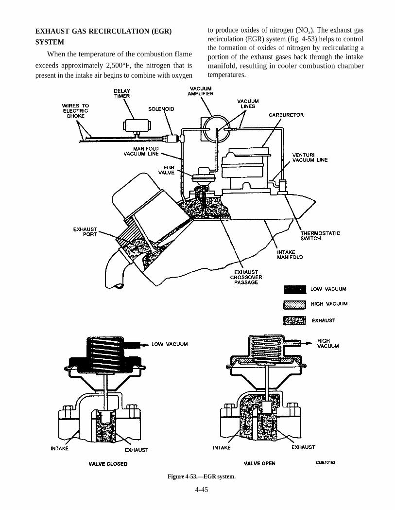
EXHAUST GAS RECIRCULATION (EGR)SYSTEM
When the temperature of the combustion flame
exceeds approximately 2,500°F, the nitrogen that ispresent in the intake air begins to combine with oxygen
to produce oxides of nitrogen (NOx). The exhaust gasrecirculation (EGR) system (fig. 4-53) helps to controlthe formation of oxides of nitrogen by recirculating aportion of the exhaust gases back through the intakemanifold, resulting in cooler combustion chambertemperatures.
Figure 4-53.—EGR system.
4-45

A basic EGR system is simple, consisting of avacuum operated EGR valve and a vacuum line fromthe carburetor. The EGR valve usually bolts to theengine intake manifold or a carburetor plate. Exhaustgases are routed through the cylinder head and intakemanifold to the EGR valve.
The EGR valve consists of a vacuum diaphragm, aspring, an exhaust gas valve, and a diaphragm housing.It is designed to control exhaust flow into the intakemanifold.
Though there are minor differences betweensystems, the basic operation of an exhaust gasrecirculation system is as follows:
At idle, the throttle plate in the carburetor or fuelinjection throttle body is closed. This blocks off enginevacuum, so it cannot act on the EGR valve. The EGRspring holds the valve shut, and the exhaust gases doNOT enter the intake manifold. If the EGR valve wereto open at idle, it could upset the air-fuel mixture and theengine would stall.
When the throttle plate is swung open to increasespeed, engine vacuum is applied to the EGR hose.Vacuum pulls the EGR diaphragm up. In turn, thediaphragm pulls the valve open. Engine exhaust canenter the intake manifold and combustion chambers. Athigher engine speeds, there is enough air flowing intothe engine that the air-fuel mixture is not upset by theopen EGR valve.
There are two different methods of supply vacuumto the EGR valve as follows:
The first method uses a vacuum port into thecarburetor throat located just above the throttle plate.As the throttle begins to open, vacuum will begin to beapplied to the port and operates the EGR valve. Thevalve will continue to operate fully until approximatelyhalf throttle is reached. As the throttle is open past thehalfway point, exhaust gas recirculation gradually willdiminish to zero, as the throttle approaches the fullyopened position.
The second method uses a vacuum port that isdirectly in the carburetor venturi (fig. 4-53). Thecarburetor venturi provides vacuum for the EGR valveany time the engine is running at high speed. Theproblem with using venturi vacuum is that it is notstrong enough to open the EGR valve. So to make itwork, manifold vacuum is used to operate the EGRvalve through a vacuum amplifier. The vacuumamplifier switches the manifold vacuum supply to the
EGR valve whenever venturi vacuum is applied to itssignal port. At times of large engine loading (wide,open throttle), manifold vacuum will be weak,producing the desired condition of no exhaust gasrecirculation.
An engine coolant temperature switch may be usedto prevent exhaust gas recirculation when the engine iscold. A cold engine does not have extremely highcombustion temperatures and does not produce verymuch NOx. By blocking vacuum to the EGR valvebelow 100°F, you can improve the drivability andperformance of the cold engine.
FUEL EVAPORIZATION CONTROLSYSTEM
The fuel evaporization control system preventsvapors from the fuel tank and carburetor from enteringthe atmosphere (fig. 4-54). Older, pre-emissionvehicles used vented fuel tank caps. Carburetor bowlswere also vented to the atmosphere. This caused aconsiderable amount of emissions. Modern vehiclescommonly use fuel evaporization control systems toprevent this source of pollution. The major componentsof the fuel evapotization control systems are the sealedfuel tank cap, fuel air dome, liquid-vapor separator, roll-over valve, fuel tank vent line, charcoal canister,carburetor vent line, and the purge line.
SEALED FUEL TANK CAP is used to keep fuelvapors from entering the atmosphere through the tankfiller neck. It may contain pressure and vacuum valvesthat open in extreme cases of pressure or vacuum.When the fuel expands (from warming), tank pressureforces fuel vapors out a vent line or line at the top of thefuel tank, not out of the cap.
FUEL AIR DOME is a hump designed into thetop of the fuel tank to allow for fuel expansion. Thedome normally provides about 10 percent air space toallow for fuel heating and volume increase.
LIQUID-VAPOR SEPARATOR is frequentlyused to keep liquid fuel from entering the evaporationcontrol system. It is simply a metal tank located abovethe main fuel tank. Liquid fuel condenses on the wallsof the separator and then flows back into the fuel tank.
ROLL-OVER VALVE is sometimes used in thevent line from the fuel tank. It keeps liquid fuel fromentering the vent line after an accident where the vehiclerolled upside down. The valve contains a metal ball orplunger valve that blocks the vent line when the valve isturned over.
4-46

Figure 4-54.—Fuel evaporization system.
FUELTANK VENTLINE carries fuel vapors up Basic operation of a fuel evaporization control
to a charcoal canister in the engine compartment. system is as follows:
CHARCOAL CANISTER stores fuel vaporswhen the engine is NOT running. The metal or plasticcanister is filled with activated charcoal granulescapable of absorbing fuel vapors.
CARBURETOR VENT LINE connects thecarburetor fuel bowl with the charcoal canister. Bowlvapors flow through this line and into the canister.
PURGE LINE is used for removing or cleaningthe stored vapors out of the charcoal canister. Itconnects the canister and the engine intake manifold.
When the engine is running, intake manifoldvacuum acts on the purge line, causing fresh air to flowthrough the filter at the bottom of the canister. Theincoming fresh air picks up the stored fuel vapors andcarries them through the purge line. The vapors enterthe intake manifold and are pulled into the combustionchambers for burning.
When the engine is shut off, engine heatproduces excess vapors. These vapors flow through thecarburetor vent line and into the charcoal canister forstorage. The vapors that form in the tank flow through
4-47
the liquid vapor separator into the tank vent line to the Q13. What material(s) is used in a catalytic convertercharcoal canister. ‘The charcoal canister absorbs these to act(s) as a catalyst?
fuel vapors and holds them until the engine is started Q14. What type of catalytic converter is of aagain. honeycomb design?
Q12. A gasoline engine produces what three major Q15. What device is used to prevent exhaust gaspollutants? recirculation when the engine is cold?
4-48

CHAPTER 5
DIESEL FUEL SYSTEMS
LEARNING OBJECTIVE: Describe the different type of diesel fuel systems,how the components function to provide fuel to the engine in proper quantities,and servicing of the diesel fuel systems.
Maintenance personnel form part of an importantnetwork of dedicated people who ensure that medium-and heavy-duty trucks and construction equipment arekept in a state of safe and acceptable performancestandards. The diesel fuel injection system is a majorcomponent of a properly operating engine. An engineout of adjustment can cause excessive exhaust smoke,poor fuel economy, heavy carbon buildup within thecombustion chambers, and short engine life.
DIESEL FUEL SYSTEMS
LEARNING OBJECTIVE: Identify theproperties of diesel fuel. Describe the functionand operation of governors and fuel systemcomponents.
Like the gasoline engine, the diesel engine is aninternal combustion engine using either a two- or four-stroke cycle. Burning or combustion of fuel within theengine cylinders obtains power. The diesel engine doesnot use a carburetor because the diesel fuel is mixed inthe cylinder with compressed air.
Compression ratios in the diesel engine rangebetween 14:1 and 19:1. This high ratio causes increasedcompression pressures of 400 to 600 psi and cylindertemperature reach 800°F to 1200°F. At the proper time,the diesel fuel is injected into the cylinder by a fuelinjection system, which usually consists of a pump, fuelline, and injector or nozzle. When the fuel oil enters thecylinder, it will ignite because of the high temperatures.The diesel engine is known as a COMPRESSION-IGNITION engine, while the gasoline engine is aSPARK-IGNITION engine.
Figure 5-1 shows the comparison of the four strokesof a four-cycle diesel engine and a four-cycle gasolineengine.
The speed of a diesel engine is controlled by theamount of fuel injected into the cylinders. In a gasolineengine, the speed of the engine is controlled by theamount of air admitted into the carburetor or gasolinefuel injection systems.
Mechanically, the diesel engine is similar to thegasoline engine. The intake, compression, power, andexhaust strokes occur in the same order. Thearrangement of the pistons, connecting rods,crankshaft, and engine valves is about the same. Thediesel engine is also classified as IN-LINE or V-TYPE.
In comparison to the gasoline engine, the dieselengine produces more power per pound of fuel, is morereliable, has lower fuel consumption per horsepowerper hour, and presents less of a fire hazard.
These advantages are partially offset by higherinitial cost, heavier construction needed for its highcompression pressures, and the difficulty in startingwhich results from these pressures.
DIESEL FUEL
Diesel fuel is heavier than gasoline because it isobtained from the residue of the crude oil after the morevolatile fuels have been removed. As with gasoline, theefficiency of diesel fuel varies with the type of engine inwhich it is used. By distillation, cracking, and blendingof several oils, a suitable diesel fuel can be obtained forall engine operating conditions. Using a poor orimproper grade of fuel can cause hard starting,incomplete combustion, a smoky exhaust, and engineknocks.
The high injection pressures needed in the dieselfuel system result from close tolerances in the pumpsand injectors. These tolerances make it necessary forthe diesel fuel to have sufficient lubrication qualities toprevent rapid wear or damage. It must also be clean,
5-1
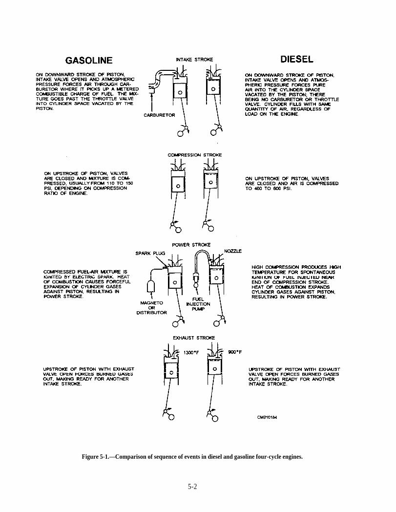
Figure 5-1.—Comparison of sequence of events in diesel and gasoline four-cycle engines.
5-2

mix rapidly with the air, and burn smoothly to producean even thrust on the piston during combustion.
Diesel Fuel Oil Grades
Diesel fuel is graded and designated by theAmerican Society for Testing and Materials (ASTM),while its specific gravity and high and low heat valuesare listed by the American Petroleum Institute (API).Each individual oil refiner and supplier attempts toproduce diesel fuels that comply as closely as possiblewith ASTM and API specifications. Because ofdifferent crude oil supplies, the diesel fuel may be oneither the high or low end of the prescribed heat scale inBtu per pound or per gallon. Because of deterioration ofdiesel fuel, there are only two recommended grades offuel that is considered acceptable for use in high-speedheavy-duty vehicles. These are the No. 1D or No. 2Dfuel oil classification
Grade No. 1D comprises the class of volatile fueloils from kerosene to the intermediate distillates. Fuelswithin this classification are applicable for use in high-speed engines in service involving frequent andrelatively wide variations in loads and speeds. In coldweather conditions, No. 1D fuel allows the engine tostart easily. In summary, for heavy-duty high-speeddiesel vehicles operating in continued cold-weatherconditions, No. 1D fuel provides better operation thanthe heavier No. 2D.
Grade No. 2D includes the class of distillate oils oflower volatility. They are applicable for use in high-speed engines in service involving relatively high loadsand speeds. This fuel is used more by truck fleets, due toits greater heat value per gallon, particularly in warm tomoderate climates. Even though No. 1D fuel has betterproperties for cold weather operations, many still useNo. 2D in the winter, using fuel heater/water separatorsto provide suitable starting, as well as fuel additiveconditioners, which are added directly into the fueltank.
Selecting the correct diesel fuel is a must if theengine is to perform to its rated specifications.Generally, the seven factors that must be considered inthe selection of a fuel oil are as follows:
1. Starting characteristics
2. Fuel handling
3. Wear on injection equipment
4. Wear on pistons
5. Wear on rings, valves, and cylinder liners
6. Engine maintenance
7. Fuel cost and availability
Other considerations in the selection of a fuel oil areas follows:
Atmospheric conditions
Frequency of load and speed changes
Speed and load range
Engine size and design
Cetane Number
Cetane number is a measure of the fuel oilsvolatility; the higher the rating, the easier the enginewill start and the combustion process will be smootherwithin the ratings specified by the engine manufacturer.Current 1D and 2D diesel fuels have a cetane ratingbetween 40 and 45.
Cetane rating differs from octane rating that is usedin gasoline in that the higher the number of gasoline onthe octane scale, the greater the fuel resistance to self-ignition, which is a desirable property in gasolineengines with a high compression ratio. Using a lowoctane fuel will cause pm-ignition in high compressionengines. However, the higher the cetane rating, theeasier the fuel will ignite once injected into the dieselcombustion chamber. If the cetane number is too low,you will have difficulty in starting. This can beaccompanied by engine knock and puffs of white smokeduring warm-up in cold weather.
High altitudes and low temperatures require the useof diesel fuel with an increased cetane number. Lowtemperature starting is enhanced by high cetane fuel oilin the proportion of 1.5°F—lower starting temperaturefor each cetane number increase in the fuel.
Volatility
Fuel volatility requirements depend on the samefactors as cetane number. The more volatile fuels arebest for engines where rapidly changing loads andspeeds are encountered. Low volatile fuels tend to givebetter fuel economy where their characteristics areneeded for complete combustion and will produce lesssmoke, odor, deposits, crankcase dilution, and enginewear.
The volatility of a fuel is established by adistillation test where a given volume of fuel is placedinto a container that is heated gradually. The readiness
5-3
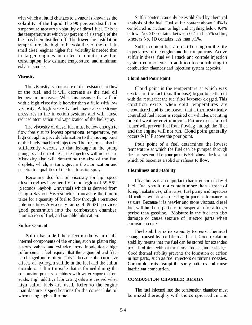
with which a liquid changes to a vapor is known as thevolatility of the liquid The 90 percent distillationtemperature measures volatility of diesel fuel. This isthe temperature at which 90 percent of a sample of thefuel has been distilled off. The lower the distillationtemperature, the higher the volatility of the fuel. Insmall diesel engines higher fuel volatility is needed thanin larger engines in order to obtain low fuelconsumption, low exhaust temperature, and minimumexhaust smoke.
Viscosity
The viscosity is a measure of the resistance to flowof the fuel, and it will decrease as the fuel oiltemperature increases. What this means is that a fluidwith a high viscosity is heavier than a fluid with lowviscosity. A high viscosity fuel may cause extremepressures in the injection systems and will causereduced atomization and vaporization of the fuel spray.
The viscosity of diesel fuel must be low enough toflow freely at its lowest operational temperature, yethigh enough to provide lubrication to the moving partsof the finely machined injectors. The fuel must also besufficiently viscous so that leakage at the pumpplungers and dribbling at the injectors will not occur.Viscosity also will determine the size of the fueldroplets, which, in turn, govern the atomization andpenetration qualities of the fuel injector spray.
Recommended fuel oil viscosity for high-speeddiesel engines is generally in the region of 39 SSU(Seconds Saybolt Universal) which is derived fromusing a Saybolt Viscosimeter to measure the time ittakes for a quantity of fuel to flow through a restrictedhole in a tube. A viscosity rating of 39 SSU providesgood penetration into the combustion chamber,atomization of fuel, and suitable lubrication.
Sulfur Content
Sulfur has a definite effect on the wear of theinternal components of the engine, such as piston ring,pistons, valves, and cylinder liners. In addition a highsulfur content fuel requires that the engine oil and filterbe changed more often. This is because the corrosiveeffects of hydrogen sulfide in the fuel and the sulfurdioxide or sulfur triioxide that is formed during thecombustion process combines with water vapor to formacids. High additive lubricating oils are desired whenhigh sulfur fuels are used. Refer to the enginemanufacturer’s specifications for the correct lube oilwhen using high sulfur fuel.
Sulfur content can only be established by chemicalanalysis of the fuel. Fuel sulfur content above 0.4% isconsidered as medium or high and anything below 0.4%is low. No. 2D contains between 0.2 and 0.5% sulfur,whereas No. 1D contains less than 0.1%.
Sulfur content has a direct bearing on the lifeexpectancy of the engine and its components. Activesulfur in diesel fuel will attack and corrode injectionsystem components in addition to contributing tocombustion chamber and injection system deposits.
Cloud and Pour Point
Cloud point is the temperature at which waxcrystals in the fuel (paraffin base) begin to settle outwith the result that the fuel filter becomes clogged. Thiscondition exists when cold temperatures areencountered and is the reason that a thermostaticallycontrolled fuel heater is required on vehicles operatingin cold weather environments. Failure to use a fuelheater will prevent fuel from flowing through the filterand the engine will not run. Cloud point generallyoccurs 9-14°F above the pour point.
Pour point of a fuel determines the lowesttemperature at which the fuel can be pumped throughthe fuel system. The pour point is 5°F above the level atwhich oil becomes a solid or refuses to flow.
Cleanliness and Stability
Cleanliness is an important characteristic of dieselfuel. Fuel should not contain more than a trace offoreign substances; otherwise, fuel pump and injectorsdifficulties will develop leading to poor performance orseizure. Because it is heavier and more viscous, dieselfuel will hold dirt particles in suspension for a longerperiod than gasoline. Moisture in the fuel can alsodamage or cause seizure of injector parts whencorrosion occurs.
Fuel stability is its capacity to resist chemicalchange caused by oxidation and heat. Good oxidationstability means that the fuel can be stored for extendedperiods of time without the formation of gum or sludge.Good thermal stability prevents the formation or carbonin hot parts, such as fuel injectors or turbine nozzles.Carbon deposits disrupt the spray patterns and causeinefficient combustion.
COMBUSTION CHAMBER DESIGN
The fuel injected into the combustion chamber mustbe mixed thoroughly with the compressed air and
5-4
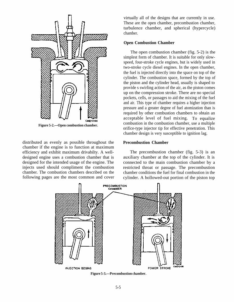
Figure 5-2.—Open combustion chamber.
distributed as evenly as possible throughout thechamber if the engine is to function at maximumefficiency and exhibit maximum drivabilty. A well-designed engine uses a combustion chamber that isdesigned for the intended usage of the engine. Theinjects used should compliment the combustionchamber. The combustion chambers described on thefollowing pages are the most common and cover
Figure 5-3.—Precombustion chamber.
5-5
virtually all of the designs that are currently in use.These are the open chamber, precombustion chamber,turbulence chamber, and spherical (hypercycle)chamber.
Open Combustion Chamber
The open combustion chamber (fig. 5-2) is thesimplest form of chamber. It is suitable for only slow-speed, four-stroke cycle engines, but is widely used intwo-stroke cycle diesel engines. In the open chamber,the fuel is injected directly into the space on top of thecylinder. The combustion space, formed by the top ofthe piston and the cylinder head, usually is shaped toprovide s swirling action of the air, as the piston comesup on the compression stroke. There are no specialpockets, cells, or passages to aid the mixing of the fueland air. This type of chamber requires a higher injectionpressure and a greater degree of fuel atomization than isrequired by other combustion chambers to obtain anacceptable level of fuel mixing. To equalizecombustion in the combustion chamber, use a multipleorifice-type injector tip for effective penetration. Thischamber design is very susceptible to ignition lag.
Precombustion Chamber
The precombustion chamber (fig. 5-3) is anauxiliary chamber at the top of the cylinder. It isconnected to the main combustion chamber by arestricted throat or passage. The precombustionchamber conditions the fuel for final combustion in thecylinder. A hollowed-out portion of the piston top
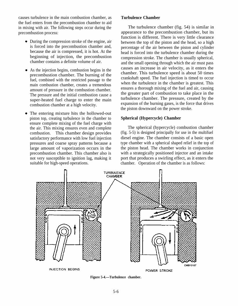
causes turbulence in the main combustion chamber, asthe fuel enters from the precombustion chamber to aidin mixing with air. The following steps occur during theprecombustion process:
During the compression stroke of the engine, airis forced into the precombustion chamber and,because the air is compressed, it is hot. At thebeginning of injection, the precombustionchamber contains a definite volume of air.
As the injection begins, combustion begins in theprecombustion chamber. The burning of thefuel, combined with the restricted passage to themain combustion chamber, creates a tremendousamount of pressure in the combustion chamber.The pressure and the initial combustion cause asuper-heated fuel charge to enter the maincombustion chamber at a high velocity.
The entering mixture hits the hollowed-outpiston top, creating turbulence in the chamber toensure complete mixing of the fuel charge withthe air. This mixing ensures even and completecombustion. This chamber design providessatisfactory performance with low fuel injectionpressures and coarse spray patterns because alarge amount of vaporization occurs in theprecombustion chamber. This chamber also isnot very susceptible to ignition lag, making itsuitable for high-speed operations.
Turbulence Chamber
The turbulence chamber (fig. 54) is similar inappearance to the precombustion chamber, but itsfunction is different. There is very little clearancebetween the top of the piston and the head, so a highpercentage of the air between the piston and cylinderhead is forced into the turbulence chamber during thecompression stroke. The chamber is usually spherical,and the small opening through which the air must passcauses an increase in air velocity, as it enters thechamber. This turbulence speed is about 50 timescrankshaft speed. The fuel injection is timed to occurwhen the turbulence in the chamber is greatest. Thisensures a thorough mixing of the fuel and air, causingthe greater part of combustion to take place in theturbulence chamber. The pressure, created by theexpansion of the burning gases, is the force that drivesthe piston downward on the power stroke.
Spherical (Hypercycle) Chamber
The spherical (hypercycle) combustion chamber(fig. 5-5) is designed principally for use in the multifueldiesel engine. The chamber consists of a basic opentype chamber with a spherical shaped relief in the top ofthe piston head. The chamber works in conjunctionwith a strategically positioned injector and an intakeport that produces a swirling effect, as it enters thechamber. Operation of the chamber is as follows:
Figure 5-4.—Turbulence chamber.
5-6
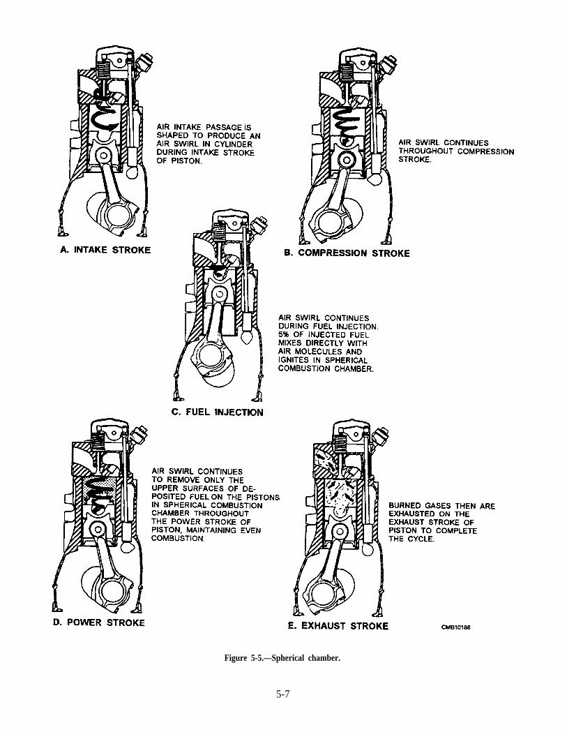
Figure 5-5.—Spherical chamber.
5-7
1. As the air enters the combustion chamber, theshape of the intake port (fig. 5-5) introduces aswirling effect to it.
2. During the compression stroke, the swirlingmotion of the air continues as the temperature inthe chamber increases (fig. 5-5).
3. As the fuel is injected, approximately 95 percentof it is deposited on the head of the piston andthe remainder mixes with the air in the sphericalcombustion chamber (fig. 5-5).
4. As combustion begins, the main portion of thefuel is swept off the piston head by the high-velocity swirl that was created by the intake andthe compression strokes. As the fuel is swept offof the head, it burns through the power stroke,maintaining even combustion and eliminatingdetonation (fig. 5-5).
GOVERNORS
A governor is required on a diesel engine to controlthe idling and maximum speeds of the engine, withsome governors being designed to control the speedwithin the overall operating range of the engine. It ispossible for the operator to control the engine speedbetween idle and maximum through the operation of thethrottle. Idle and maximum speeds must be controlledto prevent the engine from stalling during low-speedidle and to keep the speed from exceeding the maximumdesired limits desired by the manufacturer. The mainreason that a diesel requires a governor is that a dieselengine operates with excess air under all loads andspeeds.
Even though it is not part of the fuel system, agovernor is directly related to this system since itfunctions to regulate speed by the control of fuel or ofthe air-fuel mixture, depending on the type of engine. Indiesel engines governors are connected in the linkagebetween the throttle and the fuel injectors. Thegovernor acts through the fuel injection equipment toregulate the amount of fuel delivered to the cylinders.As a result the governor holds engine speed reasonablyconstant during fluctuations in load.
Before discussing governor types and operations,governor terms should be addressed and understoodsince they are commonly used when discussing enginespeed regulation.
Terms
To understand why different types of governors areneeded for different kinds of job, you will need to knowthe meaning of several terms that are used in describingthe characteristics of action of the governor.
Maximum no-load speed or high idle is used todescribe the highest engine rpm obtainable whenthe throttle linkage is moved to its maximumposition with no load applied to the engine.
Maximum full-load speed or rated speed isused to indicate the engine rpm at which aparticular engine will produce its maximumdesigned horsepower setting as stated by themanufacturer.
Idle or low-idle speed is used to indicate thenormal speed at which the engine will rotate withthe throttle linkage in the released or closedposition,
Work capacity is used to describe the amount ofavailable work energy that can be produced tothe output shaft of the governor.
Stability refers to the ability of the governor tomaintain speed with either constant or varyingloads without hunting.
Speed droop is used to express the difference inthe change in the governor rotating speed whichcauses the output shaft of the governor to movefrom its full-open throttle position to its full-closed position or vice versa.
Hunting is a repeated and sometimes rhythmicvariation of speed due to overcontrol by thegovernor. Also called speed drift.
Sensitivity is an expression of how quickly thegovernor responds to a speed change.
Response time is normally the time taken inseconds for the fuel linkage to be moved from ano-load to a full-load position.
Isochronous is used to indicate zero-droopcapability. In others words, the full-load and no-load speeds are the same.
Overrun is used to express the action of thegovernor when the engine exceeds its maximumgoverned speed.
5-8
Underrun is a simple term to describe the abilityof the governor to prevent engine speed fromdropping below a set idle, particularly when thethrottle has been moved rapidly to a decreasedfuel setting from maximum full-load position.
Deadband is the change in speed requiredbefore the governor will make a correctivemovement of the throttle.
State of balance is used to describe the speed atwhich the centrifugal force of the rotatingflyweights of the governor matches and balancesthe spring force of the governor.
Types of Governors
The type of governor used on diesel engines isdependent upon the application required. The six basictypes of governors are as follows:
1.
2.
3.
4.
5.
6.
Mechanical centrifugal flyweight style thatrelies on a set of rotating flyweights and acontrol spring; used since the inception of thediesel engine to control its speed.
Power-assisted servomechanical style thatoperates similar to the mechanical centrifugalflyweight but uses engine oil under pressure tomove the operating linkage.
Hydraulic governor that relies on the movementof a pilot valve plunger to control pressurized oilflow to a power piston, which, in turn, moves thefuel control mechanism.
Pneumatic governor that is responsive to the airflow (vacuum) in the intake manifold of anengine. A diaphragm within the governorhousing is connected to the fuel control linkagethat changes its setting with increases ordecreases in the vacuum.
Electromechanical governor uses a magneticspeed pickup sensor on an engine-drivencomponent to monitor the rpm of the engine.The sensor sends a voltage signal to anelectronic control unit that controls the currentflow to a mechanical actuator connected to thefuel linkage.
Electronic governor uses magnetic speed sensorto monitor the rpm of the engine. The sensorcontinuously feeds information back to theECM (electronic control module). The ECM
then computes all the information sent from allother engine sensors, such as the throttleposition sensor, turbocharger-boost sensor,engine oil pressure and temperature sensor,engine coolant sensor, and fuel temperature tolimit engine speed.
The governors, used on heavy-duty truckapplications and construction equipment, fall into oneof two basic categories:
1. Limiting-speed governors, sometimes referredto as minimum/maximum models since they areintended to control the idle and maximum speedsettings of the engine. Normally there is nogovernor control in the intermediate range,being regulated by the position of the throttlelinkage.
2. Variable-speed or all range governors that aredesigned to control the speed of the engineregardless of the throttle setting.
Other types of governors used on diesel engines areas follows:
1.
2.
3.
4.
Constant-speed, intended to maintain the engineat a single speed from no load to full load.
Load limiting, to limit the load applied to theengine at any given speed. Preventsoverloading the engine at whatever speed it maybe running.
Load-control, used for adjusting to the amountof load applied at the engine to suit the speed atwhich it is set to run.
Pressure regulating, used on an engine driving apump to maintain a constant inlet or outletpressure on the pump.
At this time on heavy-duty truck and constructionequipment applications, straight mechanically designedunits dominate the governor used on nonelectronic fuelinjection systems.
Mechanical Governors
In most governors installed on diesel engines usedby the Navy, the centrifugal force of rotating weights(flyballs) and the tensions of a helical coil spring (orsprings) are used in governor operation. On this basis,most of the governors used on diesel engines aregenerally called mechanical centrifugal flyweightgovernors.
5-9
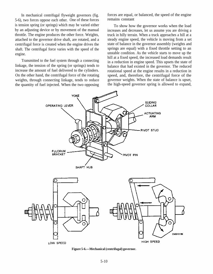
In mechanical centrifugal flyweight governors (fig.5-6), two forces oppose each other. One of these forcesis tension spring (or springs) which may be varied eitherby an adjusting device or by movement of the manualthrottle. The engine produces the other force. Weights,attached to the governor drive shaft, are rotated, and acentrifugal force is created when the engine drives theshaft. The centrifugal force varies with the speed of theengine.
Transmitted to the fuel system through a connectinglinkage, the tension of the spring (or springs) tends toincrease the amount of fuel delivered to the cylinders.On the other hand, the centrifugal force of the rotatingweights, through connecting linkage, tends to reducethe quantity of fuel injected. When the two opposing
forces are equal, or balanced, the speed of the engineremains constant
To show how the governor works when the loadincreases and decreases, let us assume you are driving atruck in hilly terrain. When a truck approaches a hill at asteady engine speed, the vehicle is moving from a setstate of balance in the governor assembly (weights andsprings are equal) with a fixed throttle setting to anunstable condition. As the vehicle starts to move up thehill at a fixed speed, the increased load demands resultin a reduction in engine speed. This upsets the state ofbalance that had existed in the governor. The reducedrotational speed at the engine results in a reduction inspeed, and, therefore, the centrifugal force of thegovernor weights. When the state of balance is upset,the high-speed governor spring is allowed to expand,
Figure 5-6.—Mechanical (centrifugal) governor.
5-10

giving up some of its stored energy, which moves theconnecting fuel linkage to an increased deliveryposition. This additional fuel delivered to thecombustion chambers would result in an increase inhorsepower, but not necessarily an increase in enginespeed.
When the truck moves into a downhill situation, theoperator is forced to back off the throttle to reduce thespeed of the vehicle; otherwise, the brakes orengine/transmission retarder has to be applied. Theoperator can also downshift the transmission to obtainadditional braking power. However, when the operatordoes not reduce the throttle position or brake the vehiclemass in some way, an increase in road speed results.This is due to the reduction in engine load because of theadditional reduction in vehicle resistance achievedthrough the mass weight of the vehicle and its loadpushing the truck downhill. This action causes thegovernor weights to increase in speed, and they attemptto compress the high-speed spring, thereby reducing thefuel delivery to the engine. Engine overspeed can resultif the road wheels of the vehicle are allowed to rotatefast enough that they, in effect, become the drivingmember.
The governor assembly would continue to reducefuel supply to the engine due to increased speed of theengine. If overspeed does occur, the valves can end upfloating (valve springs are unable to pull and keep thevalves closed) and striking the piston crown. Therefore,it is necessary in a downhill run for the operator toensure that the engine speed does not exceed maximumgoverned rpm by application of the vehicle, engine, ortransmission forces.
Favorable, as well as unfavorable, characteristicsare to be found in mechanical governors. Advantagesare as follows:
They are inexpensive.
They are satisfactory when it is not necessary tomaintain exactly the same speed, regardless ofload.
They are extremely simple with few parts.
Disadvantages are as follows:
They have large deadbands, since the speed-measuring device must also furnish the force tomove the engine fuel control.
Their power is relatively small unless they areexcessively large.
They have an unavoidable speed droop, andtherefore cannot truly provide constant speedwhen this is needed.
Hydraulic Governors
Although hydraulic governors have more movingparts and are generally more expensive than mechanicalgovernors, they are used in many applications becausethey are more sensitive, have greater power to move thefuel control mechanism of the engine, and can be timedfor identical speed for all loads.
In hydraulic governors (fig. 5-7), the power whichmoves the engine throttle does NOT come from thespeed-measuring device, but instead comes from ahydraulic power piston, or servomotor. This is a pistonthat is acted upon by fluid pressure, generally oil underthe pressure of a pump. By using appropriate piston sizeand oil pressure, the power of the governor at its outputshaft (work capacity) can be made sufficient to operatethe fuel-changing mechanism of the largest engines.
The speed-measuring device, through its speederrod, is attached to a small cylindrical valve, called apilot valve. The pilot valve slides up and down in abushing, which contains ports that control the oil, flowto and from the servomotor. The force needed to slidethe pilot valve is very little; a small ball head is able tocontrol a large amount of power at the servomotor.
The basic principle of a hydraulic governor (fig.5-7) is very simple. When the governor is operating atcontrol speed or state of balance, the pilot valve closesthe port and there is no oil flow.
When the governor speed falls due to an increase inengine load, the flyweights move in and the pilot valve
Figure 5-7.—Hydraulic governor.
5-11
moves down. This opens the port to the power pistonand connects the oil supply of oil under pressure. Thisoil pressure acts on the power piston, forcing it upwardto increase the fuel.
When the governor speed rises due to a decrease ofengine load, the flyweights move out and the pilot valvemoves up. This opens the port from the power piston tothe drain into the sump. The spring above the powerpiston forces the power piston down, thus decreasingthe speed.
Unfortunately, the simple hydraulic governor has aserious defect, which prevents its practical use. It isinherently unstable; that is, it keeps moving continually,making unnecessary corrective actions. In other wordsit hunts. The cause of this hunting is the unavoidabletime lag between the moment the governor acts and themoment the engine responds. The engine cannot comeback to the speed called for by the governor.
Most hydraulic governors use a speed droop toobtain stability. Speed droop gives stability because theengine throttle can take only one position for any speed.Therefore, when a load change causes a speed change,the resulting governor action ceases at a particular pointthat gives the amount of fuel needed for a new load. Inthis way speed droop prevents unnecessary governormovement and overcorrection (hunting).
Electronic Governors
5-12
The recent introduction of electronically controlleddiesel fuel injection system on several heavy-duty high-speed truck engines has allowed the speed of the dieselengine to be controlled electronically, rather thanmechanically. The same type of balance condition in amechanical governor occurs in an electronic governor.The major difference is that in the electronic governor,electric currents (amperes) and voltages (pressure) areused together instead of mechanical weight and springforces. This is possible through the use of magneticpickup sensor (MPS), which is, in effect, a permanent-magnet single-pole device. This magnetic pickupconcept is being used on all existing electronic systemsand its operation can be considered common to all ofthem. MPS’s are a vital communications link betweenthe engine crankshaft speed and the onboard computer(ECM). The MPS is installed next to a drive shaft gearmade of a material that reacts to a magnetic field. Aseach gear tooth passes the MPS, the gear interrupts theMPS’s magnetic field. This, in turn, produces an accurrent signal, which corresponds to the rpm of theengine. This signal is sent to the ECM to establish the
amount of fuel that should be injected into thecombustion chambers of the engine. Electronic speedgoverning systems are set up to provide six basicgoverning modes:
1. Idle speed control
2. Maximum speed control
3. Power takeoff speed control
4. Vehicle speed cruise control
5. Engine speed cruise control
6. Road speed limiting
Each of the control modes above is described inmore detail below.
1. The idle speed control provides fixed speedcontrol over the entire torque capability of theengine. Also, the idle speed set point iscalculated as a function of the enginetemperature to provide an optional cold idlespeed, which is usually several hundred rpmhigher than normal operating temperature.
2. The engine maximum rpm setting can beprogrammed for different settings. This canimprove fuel economy by eliminating engineoverspeed in all gear ranges.
3. The power takeoff speed control setting canoperate at any speed between idle andmaximum. The operator uses rotary control or atoggle switch in the cab to vary electronicallythe engine power to the PTO from idle to thepreset rpm.
4. Vehicle and engine cruise control includes set,resume, and coast features similar to that of apassenger car, as well as an accelerate (ACCEL)mode to provide a fixed speed increase eachtime the control switch is activated.
5. The road speed limiting function allows theorganization assigned to determine whatmaximum vehicle road speed they desireindependent of the maximum governed speedsetting of the engine. Road speed governingprovides the best method for ensuring ideal fueleconomy.
The major advantage of the electronic governorover the mechanical governor lies in its ability tomodify speed reference easily by various means tocontrol such things as acceleration and deceleration, aswell as load.
DIESEL FUEL SYSTEM COMPONENTS
Before discussing the various types of fuel injectionsystems, let’s spend some time looking at the basiccomponents that are necessary to hold, supply, and filterthe fuel before it passes to the actual injection system.The basic function of the fuel system is to provide areservoir of diesel fuel, to provide sufficient circulationof clean filtered fuel for lubrication, cooling andcombustion purposes, and to allow warm fuel from theengine to recirculate back to the tank(s). The specificlayout and arrangement of the diesel fuel system willvary slightly between makes and models.
The basic fuel system consists of the fuel tank(s)and a fuel transfer pump (supply) that can be a separateengine-driven pump or can be mounted on or inside theinjection pump. In addition, the system uses two fuelfilters—a primary and secondary filter—to removeimpurities from the fuel. In some system you will have afuel filter/water separator that contains an internal filterand water trap.
Tank and Cap
Fuel tanks used today can be constructed fromblack sheet steel, or for lighter weight, aluminum alloyis used. Baffles are welded into the tanks duringconstruction. The baffle plates are designed with holesin them to prevent the fuel from sloshing during themovement of the vehicle. The fuel lines (inlet andreturn) should be separated by a baffle in the tank toprevent warm return fuel from being sucked right backup by the fuel inlet line. Both the inlet and return linesshould be kept 2 inches above the bottom of the tank, sosediment or water is not drawn into the inlet.
A well-designed tank will contain a drain plug in thebase to allow for fuel tank drainage. This allows the fuelto be drained from the tank before removal for anyservice. Many tanks are equipped with a small low-mounted catchment basin so that any water in the tankcan be quickly drained through a drain cock, which issurrounded by a protective cage to prevent damage.
The fuel tank filler cap is constructed with both apressure relief valve and a vent valve. The vent valve isdesigned to seal when fuel enters it due to overfilling,vehicle operating angle, or sudden jolt that would causefuel slosh within the tank. Although some fuel will tendto seep from the vent cap, this leakage should notexceed 1 ounce per minute.
The diesel fuel tank is mounted directly on thechassis of construction equipment because of its weight
(when filled) and to prevent movement of the tank whenthe equipment is operated over rough terrain. Itslocation depends on the type of equipment and the useof the equipment. On equipment used for groundclearing and earthwork, the tank is mounted where it hasless chance of being damaged by foreign objects orstriking the ground.
Gauges
The electric gauges used in the diesel fuel systemare the same types as used in the gasoline fuel system.Some manufacturers use a bayonet type gaugepermanently attached to the filler cap of the fuel tank orinstalled under the fuel cap. These are graduated andthe fuel level is checked by the same method as oil in anengine.
Fuel Filters
The purpose of any diesel fuel filter is mainly toremove foreign particles as well as water. The use of asuitable filtration system on diesel engines is a must toavoid damage to closely fitted injection pump andinjector components. The components aremanufactured to tolerances as little as 0.0025 mm;therefore, insufficient fuel filtration can cause seriousproblems. Six principal filter elements have been usedfor many years:
1.
2.
3.
4.
5.
6.
Pleated paper
Packed cotton thread
Wood fibers
Mixtures of packed cotton and wood fibers
Wound cotton or synthetic yarn
Fiber glass
Filter ability will vary between the type andmanufacturer. On diesel engines a primary andsecondary filter are used. The primary filter is capableof removing dirt particles down to 30 microns and thesecondary filter between 10 to 12 microns. Secondaryfilters are available between 3 and 5 microns, which areused in severe service operations. The primary isusually located between the tank and the supply pumpand the secondary filter between the supply pump andthe injection pump. Diesel fuel filters are referred to asfull-flow filters, because all the fuel must pass throughthem before reaching the injection pumps.
Some filters use an internal replaceable elementinside a bowl or shell; these are commonly referred to as
5-13
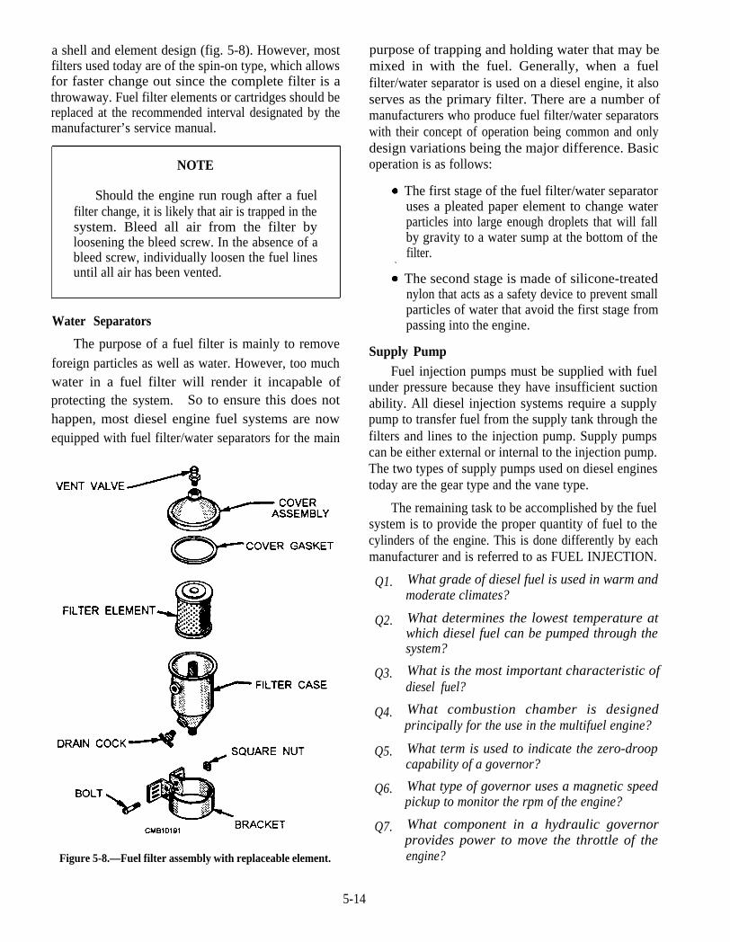
a shell and element design (fig. 5-8). However, mostfilters used today are of the spin-on type, which allowsfor faster change out since the complete filter is athrowaway. Fuel filter elements or cartridges should bereplaced at the recommended interval designated by themanufacturer’s service manual.
NOTE
Should the engine run rough after a fuelfilter change, it is likely that air is trapped in thesystem. Bleed all air from the filter byloosening the bleed screw. In the absence of ableed screw, individually loosen the fuel linesuntil all air has been vented.
Water Separators
The purpose of a fuel filter is mainly to removeforeign particles as well as water. However, too muchwater in a fuel filter will render it incapable ofprotecting the system. So to ensure this does nothappen, most diesel engine fuel systems are nowequipped with fuel filter/water separators for the main
Figure 5-8.—Fuel filter assembly with replaceable element.
purpose of trapping and holding water that may bemixed in with the fuel. Generally, when a fuelfilter/water separator is used on a diesel engine, it alsoserves as the primary filter. There are a number ofmanufacturers who produce fuel filter/water separatorswith their concept of operation being common and onlydesign variations being the major difference. Basicoperation is as follows:
The first stage of the fuel filter/water separatoruses a pleated paper element to change waterparticles into large enough droplets that will fallby gravity to a water sump at the bottom of thefilter.
The second stage is made of silicone-treatednylon that acts as a safety device to prevent smallparticles of water that avoid the first stage frompassing into the engine.
Supply PumpFuel injection pumps must be supplied with fuel
under pressure because they have insufficient suctionability. All diesel injection systems require a supplypump to transfer fuel from the supply tank through thefilters and lines to the injection pump. Supply pumpscan be either external or internal to the injection pump.The two types of supply pumps used on diesel enginestoday are the gear type and the vane type.
The remaining task to be accomplished by the fuelsystem is to provide the proper quantity of fuel to thecylinders of the engine. This is done differently by eachmanufacturer and is referred to as FUEL INJECTION.
Q1.
Q2.
Q3.
Q4.
Q5.
Q6.
Q7.
What grade of diesel fuel is used in warm andmoderate climates?
What determines the lowest temperature atwhich diesel fuel can be pumped through thesystem?
What is the most important characteristic ofdiesel fuel?
What combustion chamber is designedprincipally for the use in the multifuel engine?
What term is used to indicate the zero-droopcapability of a governor?
What type of governor uses a magnetic speedpickup to monitor the rpm of the engine?
What component in a hydraulic governorprovides power to move the throttle of theengine?
5-14
Q8. How many governing modes does the electronicspeed governing system provide?
Q9. How far should the inlet and outlet lines be fromthe bottom of a fuel tank?
METHODS OF INJECTION
LEARNING OBJECTIVE: Describe theprinciples and operation of the different dieselfuel systems.
You have probably heard the statement that "thefuel injection system is the actual heart of the dieselengine." When you consider that indeed a diesel couldnot be developed until an adequate fuel injection systemwas designed and produced, this statement takes on amuch broader and stronger meaning.
In this section, various methods of mechanicalinjections and metering control are described. Therehave been many important developments in pumps,nozzles, and unit injectors for diesel engines over theyears with the latest injection system today relying onelectronic controls and sensors.
FUEL INJECTION SYSTEMS
Diesel fuel injection systems must accomplish fiveparticular functions-meter, inject, time, atomize, andcreate pressure. A description of these functionsfollows:
1.
2.
3.
4.
5.
METER—Accurately measure the amount offuel to be injected.
INJECT—Force and distribute the fuel into thecombustion chamber.
TIME—Injection of the fuel must start and stopat the proper time.
ATOMIZE—Break the fuel up into a fine mist.
CREATE PRESSURE—Create the necessaryhigh pressure for injection.
You can remember these functions by the initials,MITAC. All five of these functions are necessary forcomplete and efficient combustion
Metering
Accurate metering or measuring of the fuel meansthat, for the same fuel control setting, the same quantityof fuel must be delivered to each cylinder for eachpower stroke of the engine. Only in this way can the
engine operate at uniform speed with uniform poweroutput. Smooth engine operation and an evendistribution of the load between the cylinders dependupon the same volume of fuel being admitted to aparticular cylinder each time it fires and upon equalvolumes of fuel beingengine.
Injection Control
delivered to all cylinders of the
A fuel system must also control the rate of injection.The rate at which fuel is injected determines the rate ofcombustion. The rate of injection at the start should below enough that excessive fuel does not accumulate inthe cylinder during the initial ignition delay (beforecombustion begins). Injection should proceed at such arate that the rise in combustion pressure is not to great,yet the rate of injection must be such that fuel isintroduced as rapidly as possible to obtain completecombustion. An incorrect rate of injection affectsengine operation in the same way as improper timing.When the rate of injection is too high, the results aresimilar to those caused by an injection that is too early;when the rate is too low, the results are similar to thosecaused by an injection that is too late.
Timing
In addition to measuring the amount of fuelinjected, the system must properly time injection toensure efficient combustion so that maximum energycan be obtained from the fuel. When the fuel is injectedtoo early in the cycle, ignition may be delayed becausethe temperature of the air, at this point, is not highenough. An excessive delay, on the other hand, givesrough and noisy operation of the engine. It also permitssome fuel to be lost due to the wetting of the cylinderwalls and piston head. This, in turn, results in poor fueleconomy, high exhaust gas temperature, and smoke inthe exhaust. When fuel is injected too late in the cycle,all the fuel will not be burned until the piston hastraveled well past top center. When this happens, theengine does not develop enough power, the exhaust issmoky, and fuel consumption is high.
Atomization of Fuel
As used in connection with fuel injection,atomization means the breaking up of the fuel, as itenters the cylinder into small particles, which form amistlike spray. Atomization of the fuel must meet therequirements of the type of combustion chamber in use.Some chambers require very fine atomization; while
5-15
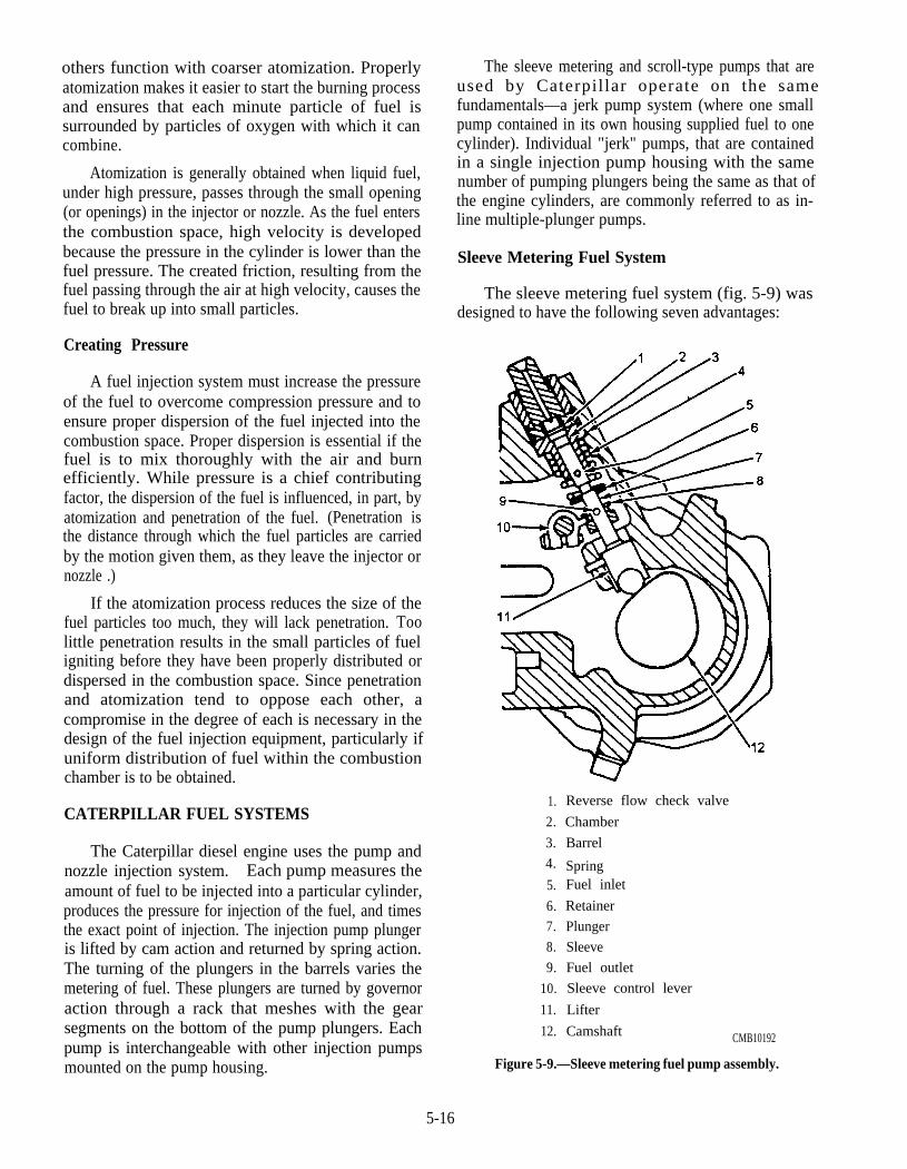
others function with coarser atomization. Properlyatomization makes it easier to start the burning processand ensures that each minute particle of fuel issurrounded by particles of oxygen with which it cancombine.
Atomization is generally obtained when liquid fuel,under high pressure, passes through the small opening(or openings) in the injector or nozzle. As the fuel entersthe combustion space, high velocity is developedbecause the pressure in the cylinder is lower than thefuel pressure. The created friction, resulting from thefuel passing through the air at high velocity, causes thefuel to break up into small particles.
Creating Pressure
A fuel injection system must increase the pressureof the fuel to overcome compression pressure and toensure proper dispersion of the fuel injected into thecombustion space. Proper dispersion is essential if thefuel is to mix thoroughly with the air and burnefficiently. While pressure is a chief contributingfactor, the dispersion of the fuel is influenced, in part, byatomization and penetration of the fuel. (Penetration isthe distance through which the fuel particles are carriedby the motion given them, as they leave the injector ornozzle .)
If the atomization process reduces the size of thefuel particles too much, they will lack penetration. Toolittle penetration results in the small particles of fueligniting before they have been properly distributed ordispersed in the combustion space. Since penetrationand atomization tend to oppose each other, acompromise in the degree of each is necessary in thedesign of the fuel injection equipment, particularly ifuniform distribution of fuel within the combustionchamber is to be obtained.
CATERPILLAR FUEL SYSTEMS
The Caterpillar diesel engine uses the pump andnozzle injection system. Each pump measures theamount of fuel to be injected into a particular cylinder,produces the pressure for injection of the fuel, and timesthe exact point of injection. The injection pump plungeris lifted by cam action and returned by spring action.The turning of the plungers in the barrels varies themetering of fuel. These plungers are turned by governoraction through a rack that meshes with the gearsegments on the bottom of the pump plungers. Eachpump is interchangeable with other injection pumpsmounted on the pump housing.
The sleeve metering and scroll-type pumps that areused by Caterpillar operate on the samefundamentals—a jerk pump system (where one smallpump contained in its own housing supplied fuel to onecylinder). Individual "jerk" pumps, that are containedin a single injection pump housing with the samenumber of pumping plungers being the same as that ofthe engine cylinders, are commonly referred to as in-line multiple-plunger pumps.
Sleeve Metering Fuel System
The sleeve metering fuel system (fig. 5-9) wasdesigned to have the following seven advantages:
1.
2.
3.
4.
5.
6.7.
8.
9.
10.
11.
12.
Reverse flow check valve
Chamber
Barrel
SpringFuel inlet
Retainer
Plunger
Sleeve
Fuel outlet
Sleeve control lever
Lifter
Camshaft CMB10192
Figure 5-9.—Sleeve metering fuel pump assembly.
5-16
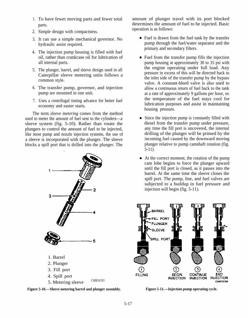
1.
2.
3.
4.
5.
6.
7.
To have fewer moving parts and fewer totalparts.
Simple design with compactness.
It can use a simple mechanical governor. Nohydraulic assist required.
The injection pump housing is filled with fueloil, rather than crankcase oil for lubrication ofall internal parts.
The plunger, barrel, and sleeve design used in allCaterpillar sleeve metering units follows acommon style.
The transfer pump, governor, and injectionpump are mounted in one unit.
Uses a centrifugal timing advance for better fueleconomy and easier starts.
The term sleeve metering comes from the methodused to meter the amount of fuel sent to the cylinders—asleeve system (fig. 5-10). Rather than rotate theplungers to control the amount of fuel to be injected,like most pump and nozzle injection systems, the use ofa sleeve is incorporated with the plunger. The sleeveblocks a spill port that is drilled into the plunger. The
1. Barrel2. Plunger3. Fill port4. Spill port5. Metering sleeve CMB10193
Figure 5-10.—Sleeve metering barrel and plunger assembly.
amount of plunger travel with its port blockeddetermines the amount of fuel to be injected. Basicoperation is as follows:
Fuel is drawn from the fuel tank by the transferpump through the fuel/water separator and theprimary and secondary filters.
Fuel from the transfer pump fills the injectionpump housing at approximately 30 to 35 psi withthe engine operating under full load. Anypressure in excess of this will be directed back tothe inlet side of the transfer pump by the bypassvalve. A constant-bleed valve is also used toallow a continuous return of fuel back to the tankat a rate of approximately 9 gallons per hour, sothe temperature of the fuel stays cool forlubrication purposes and assist in maintaininghousing pressure.
Since the injection pump is constantly filled withdiesel from the transfer pump under pressure,any time the fill port is uncovered, the internaldrilling of the plunger will be primed by theincoming fuel caused by the downward movingplunger relative to pump camshaft rotation (fig.5-11).
At the correct moment, the rotation of the pumpcam lobe begins to force the plunger upwarduntil the fill port is closed, as it passes into thebarrel. At the same time the sleeve closes thespill port. The pump, line, and fuel valves aresubjected to a buildup in fuel pressure andinjection will begin (fig. 5-11).
Figure 5-11.—Injection pump operating cycle.
5-17
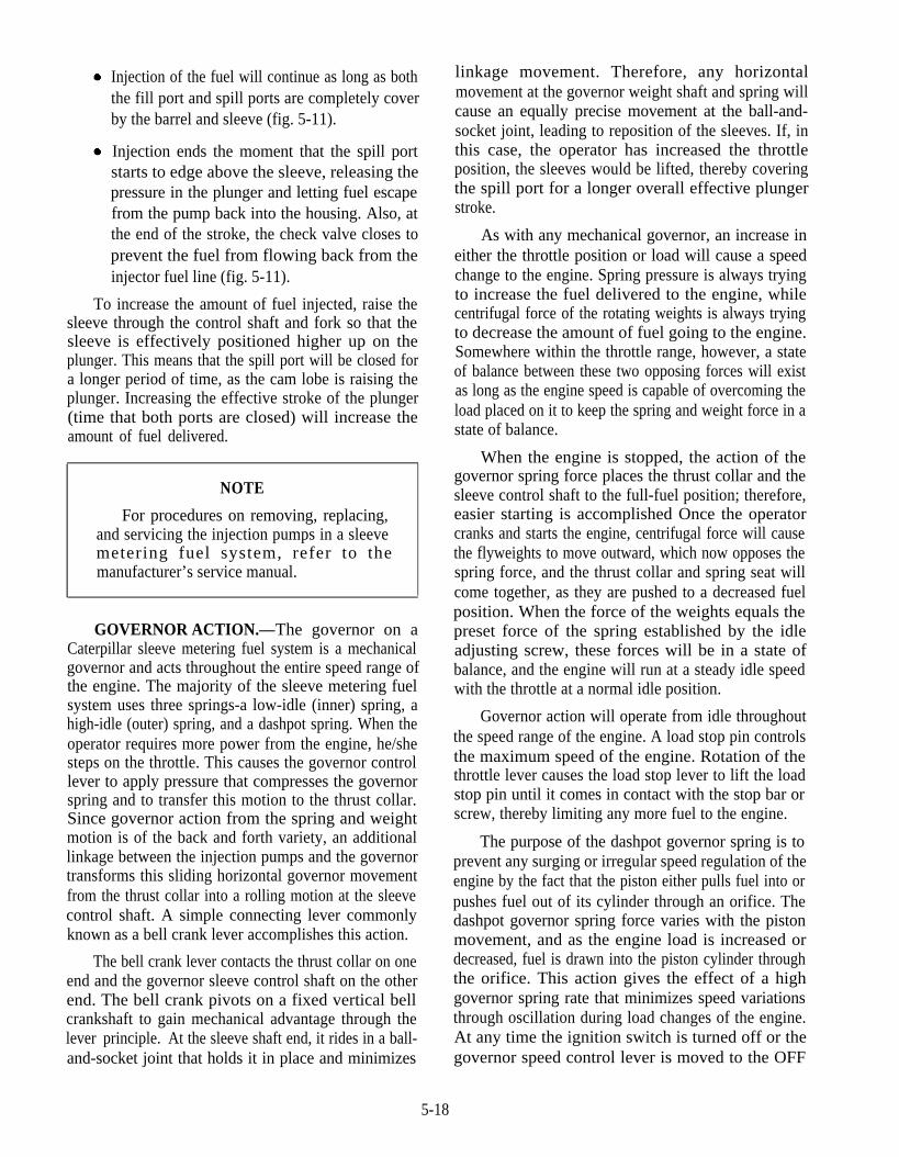
Injection of the fuel will continue as long as boththe fill port and spill ports are completely coverby the barrel and sleeve (fig. 5-11).
Injection ends the moment that the spill portstarts to edge above the sleeve, releasing thepressure in the plunger and letting fuel escapefrom the pump back into the housing. Also, atthe end of the stroke, the check valve closes toprevent the fuel from flowing back from theinjector fuel line (fig. 5-11).
linkage movement. Therefore, any horizontalmovement at the governor weight shaft and spring willcause an equally precise movement at the ball-and-socket joint, leading to reposition of the sleeves. If, inthis case, the operator has increased the throttleposition, the sleeves would be lifted, thereby coveringthe spill port for a longer overall effective plungerstroke.
To increase the amount of fuel injected, raise thesleeve through the control shaft and fork so that thesleeve is effectively positioned higher up on theplunger. This means that the spill port will be closed fora longer period of time, as the cam lobe is raising theplunger. Increasing the effective stroke of the plunger(time that both ports are closed) will increase theamount of fuel delivered.
As with any mechanical governor, an increase ineither the throttle position or load will cause a speedchange to the engine. Spring pressure is always tryingto increase the fuel delivered to the engine, whilecentrifugal force of the rotating weights is always tryingto decrease the amount of fuel going to the engine.Somewhere within the throttle range, however, a stateof balance between these two opposing forces will existas long as the engine speed is capable of overcoming theload placed on it to keep the spring and weight force in astate of balance.
NOTE
For procedures on removing, replacing,and servicing the injection pumps in a sleevemetering fuel system, refer to themanufacturer’s service manual.
5-18
GOVERNOR ACTION.—The governor on aCaterpillar sleeve metering fuel system is a mechanicalgovernor and acts throughout the entire speed range ofthe engine. The majority of the sleeve metering fuelsystem uses three springs-a low-idle (inner) spring, ahigh-idle (outer) spring, and a dashpot spring. When theoperator requires more power from the engine, he/shesteps on the throttle. This causes the governor controllever to apply pressure that compresses the governorspring and to transfer this motion to the thrust collar.Since governor action from the spring and weightmotion is of the back and forth variety, an additionallinkage between the injection pumps and the governortransforms this sliding horizontal governor movementfrom the thrust collar into a rolling motion at the sleevecontrol shaft. A simple connecting lever commonlyknown as a bell crank lever accomplishes this action.
When the engine is stopped, the action of thegovernor spring force places the thrust collar and thesleeve control shaft to the full-fuel position; therefore,easier starting is accomplished Once the operatorcranks and starts the engine, centrifugal force will causethe flyweights to move outward, which now opposes thespring force, and the thrust collar and spring seat willcome together, as they are pushed to a decreased fuelposition. When the force of the weights equals thepreset force of the spring established by the idleadjusting screw, these forces will be in a state ofbalance, and the engine will run at a steady idle speedwith the throttle at a normal idle position.
Governor action will operate from idle throughoutthe speed range of the engine. A load stop pin controlsthe maximum speed of the engine. Rotation of thethrottle lever causes the load stop lever to lift the loadstop pin until it comes in contact with the stop bar orscrew, thereby limiting any more fuel to the engine.
The bell crank lever contacts the thrust collar on oneend and the governor sleeve control shaft on the otherend. The bell crank pivots on a fixed vertical bellcrankshaft to gain mechanical advantage through thelever principle. At the sleeve shaft end, it rides in a ball-and-socket joint that holds it in place and minimizes
The purpose of the dashpot governor spring is toprevent any surging or irregular speed regulation of theengine by the fact that the piston either pulls fuel into orpushes fuel out of its cylinder through an orifice. Thedashpot governor spring force varies with the pistonmovement, and as the engine load is increased ordecreased, fuel is drawn into the piston cylinder throughthe orifice. This action gives the effect of a highgovernor spring rate that minimizes speed variationsthrough oscillation during load changes of the engine.At any time the ignition switch is turned off or thegovernor speed control lever is moved to the OFF
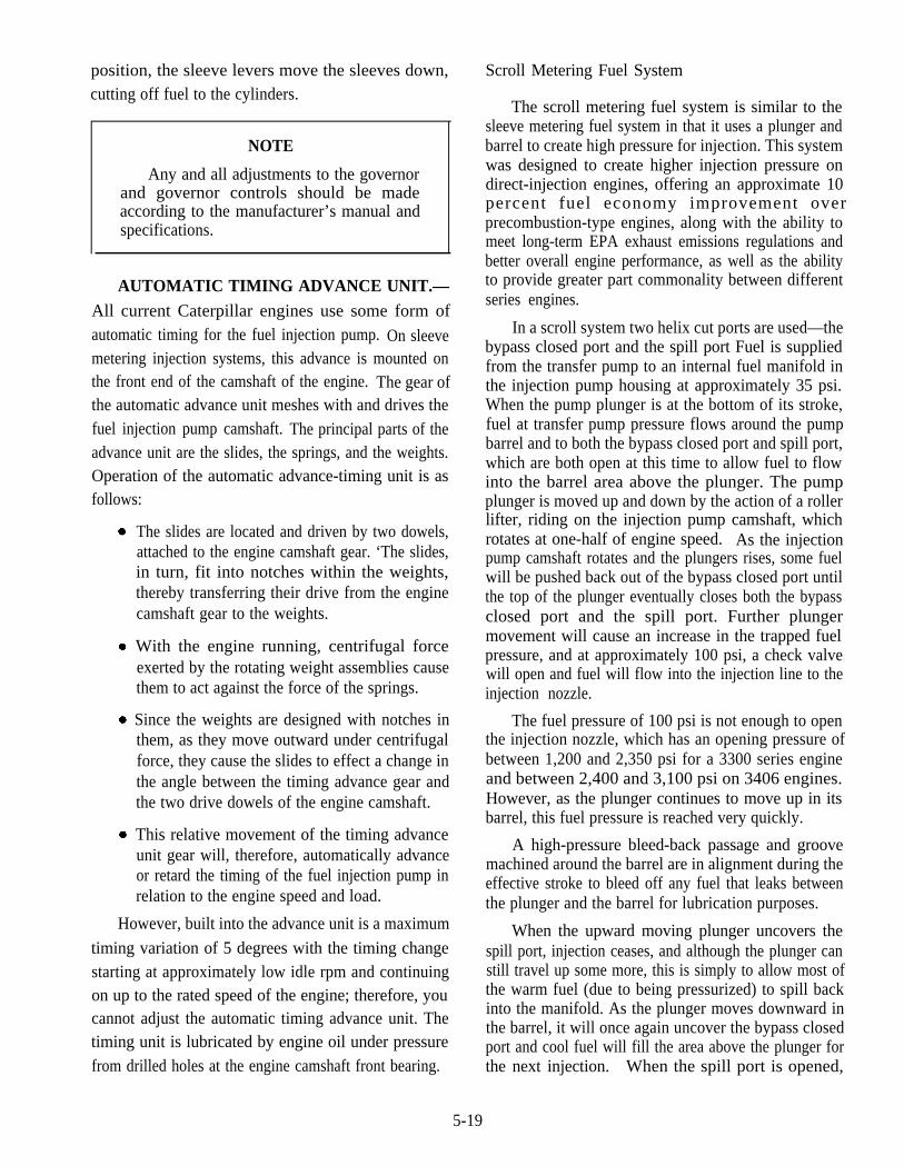
position, the sleeve levers move the sleeves down,cutting off fuel to the cylinders.
NOTE
Any and all adjustments to the governorand governor controls should be madeaccording to the manufacturer’s manual andspecifications.
AUTOMATIC TIMING ADVANCE UNIT.—All current Caterpillar engines use some form ofautomatic timing for the fuel injection pump. On sleevemetering injection systems, this advance is mounted onthe front end of the camshaft of the engine. The gear ofthe automatic advance unit meshes with and drives thefuel injection pump camshaft. The principal parts of theadvance unit are the slides, the springs, and the weights.Operation of the automatic advance-timing unit is asfollows:
The slides are located and driven by two dowels,attached to the engine camshaft gear. ‘The slides,in turn, fit into notches within the weights,thereby transferring their drive from the enginecamshaft gear to the weights.
With the engine running, centrifugal forceexerted by the rotating weight assemblies causethem to act against the force of the springs.
Since the weights are designed with notches inthem, as they move outward under centrifugalforce, they cause the slides to effect a change inthe angle between the timing advance gear andthe two drive dowels of the engine camshaft.
This relative movement of the timing advanceunit gear will, therefore, automatically advanceor retard the timing of the fuel injection pump inrelation to the engine speed and load.
However, built into the advance unit is a maximum
timing variation of 5 degrees with the timing changestarting at approximately low idle rpm and continuingon up to the rated speed of the engine; therefore, youcannot adjust the automatic timing advance unit. Thetiming unit is lubricated by engine oil under pressurefrom drilled holes at the engine camshaft front bearing.
Scroll Metering Fuel System
The scroll metering fuel system is similar to thesleeve metering fuel system in that it uses a plunger andbarrel to create high pressure for injection. This systemwas designed to create higher injection pressure ondirect-injection engines, offering an approximate 10percent fuel economy improvement overprecombustion-type engines, along with the ability tomeet long-term EPA exhaust emissions regulations andbetter overall engine performance, as well as the abilityto provide greater part commonality between differentseries engines.
In a scroll system two helix cut ports are used—thebypass closed port and the spill port Fuel is suppliedfrom the transfer pump to an internal fuel manifold inthe injection pump housing at approximately 35 psi.When the pump plunger is at the bottom of its stroke,fuel at transfer pump pressure flows around the pumpbarrel and to both the bypass closed port and spill port,which are both open at this time to allow fuel to flowinto the barrel area above the plunger. The pumpplunger is moved up and down by the action of a rollerlifter, riding on the injection pump camshaft, whichrotates at one-half of engine speed. As the injectionpump camshaft rotates and the plungers rises, some fuelwill be pushed back out of the bypass closed port untilthe top of the plunger eventually closes both the bypassclosed port and the spill port. Further plungermovement will cause an increase in the trapped fuelpressure, and at approximately 100 psi, a check valvewill open and fuel will flow into the injection line to theinjection nozzle.
The fuel pressure of 100 psi is not enough to openthe injection nozzle, which has an opening pressure ofbetween 1,200 and 2,350 psi for a 3300 series engineand between 2,400 and 3,100 psi on 3406 engines.However, as the plunger continues to move up in itsbarrel, this fuel pressure is reached very quickly.
A high-pressure bleed-back passage and groovemachined around the barrel are in alignment during theeffective stroke to bleed off any fuel that leaks betweenthe plunger and the barrel for lubrication purposes.
When the upward moving plunger uncovers thespill port, injection ceases, and although the plunger canstill travel up some more, this is simply to allow most ofthe warm fuel (due to being pressurized) to spill backinto the manifold. As the plunger moves downward inthe barrel, it will once again uncover the bypass closedport and cool fuel will fill the area above the plunger forthe next injection. When the spill port is opened,
5-19

pressure inside the barrel is released and the check valveis seated by its spring.
Within the check valve assembly is a reverse flowcheck valve that opens when fuel pressure in theinjection line remains above 1,000 psi and closes assoon as the fuel pressure drops to 1,000 psi. This willkeep the fuel lines filled with fuel at 1,000 psi and readyfor the next injection. This provides for a consistent andsmooth engine power curve.
TRANSFER PUMP.—With the introduction ofthe scroll metering fuel system, the gear-type fueltransfer pump that had been used for years byCaterpillar was superseded by the use of a piston-typetransfer pump. Current scroll metering fuel systems usea single-piston, double-acting pump with three one-waycheck valves.
The transfer pump is bolted to the low side of theinjection pump housing. It is capable of delivering up to51 gallons of fuel per hour at 25 psi. There is no need fora relief valve in this transfer pump due to the fact thatmaximum pressure is controlled automatically by theforce of the piston return spring.
The transfer pump is activated by an eccentric (adevice that converts rotary motion into reciprocatingmotion) on the injection pump camshaft, causing thepushrod to move in and out, as the engine is running.This action causes the piston to move down against theforce of the piston return spring inside the transfer pumphousing. The downward movement of the piston willcause the inlet check valve and the outlet check valve toclose, while allowing the pumping check valve to opento allow fuel below the piston to flow into the areaimmediately above the downward piston.
As the injection pump camshaft eccentric rotatesaround to its low point, the transfer pump spring pushesthe piston up inside its bore, causing the pumping checkvalve to close, and both the out and inlet valves areforced open. Fuel above the piston will be forcedthrough the outlet check valve and the pump outlet portat approximately 35 psi. As this occurs, fuel will alsoflow through the pump inlet port and the inlet checkvalve to fill the area below the piston and the pump willrepeat the cycle.
GOVERNOR.—The governor assembly usedwith the scroll metering fuel system is a hydra-mechanical servo-type unit. The reason for using aservo-valve is to provide a "boost" to the governor.Without the servo-valve, both the governor spring andflyweights would have to be very large and heavy. Withthe use of the servo assist, little force is required to move
both the accelerator and the governor control lever.Basically, the governor assembly consists of threeseparate components:
1.
2.
3.
The mechanical components of the governor,such as the weights, springs, and linkage.
The governor servo that provides hydraulicassistance through the use of pressurized engineoil to provide rapid throttle response and toreduce overall size requirement of theflyweights and springs.
The dashpot assembly that is designed toprovide stability to the governor during rapidload/throttle changes.
FUEL INJECTOR NOZZLE.—The fuel injectornozzle, used with the scroll metering fuel system, is amultiple-hole design, inward-opening, non-leakofftype. There are minor changes between the earliernozzles and current models. Older nozzles areidentified by the use of a color-coded black or bluewasher, while the newer ones use a copper washer.
The nozzle is a multiple-hole design since it is usedin direct injection engines only. The number and size ofthe holes will vary between different series of engines.For example, the 3306 engine nozzle uses a nine-holetip, while the nozzle in the 3406 uses a six-hole tip.These different nozzles cannot be intermixed in thesame engine or switched from one series engine toanother.
The nozzle is designed for injection pressures of15,000 psi and short injection duration to prevent a lossin fuel economy due to stringent EPA emissionrequirements. The nozzle incorporates a carbon dam onthe lower end of the pencil part of the body and a sealwasher on the upper end. The carbon dam preventscarbon blow-by into the nozzle bore in the cylinderhead, while the upper seal prevents compressionleakage from the cylinder. Injector nozzle operation isas follows:
The nozzle receives high-pressure fuel from thefuel pump through the inlet passage and filterscreen and into the fuel passage.
When fuel pressure is high enough, the injectorvalve is lifted against the force of the returnspring and fuel is injected through the multipleholes in the spray tip. This causes an increase infuel pressure and the fuel to be finely atomizedspray for penetration of the compressed air in thecombustion chamber.
5-20
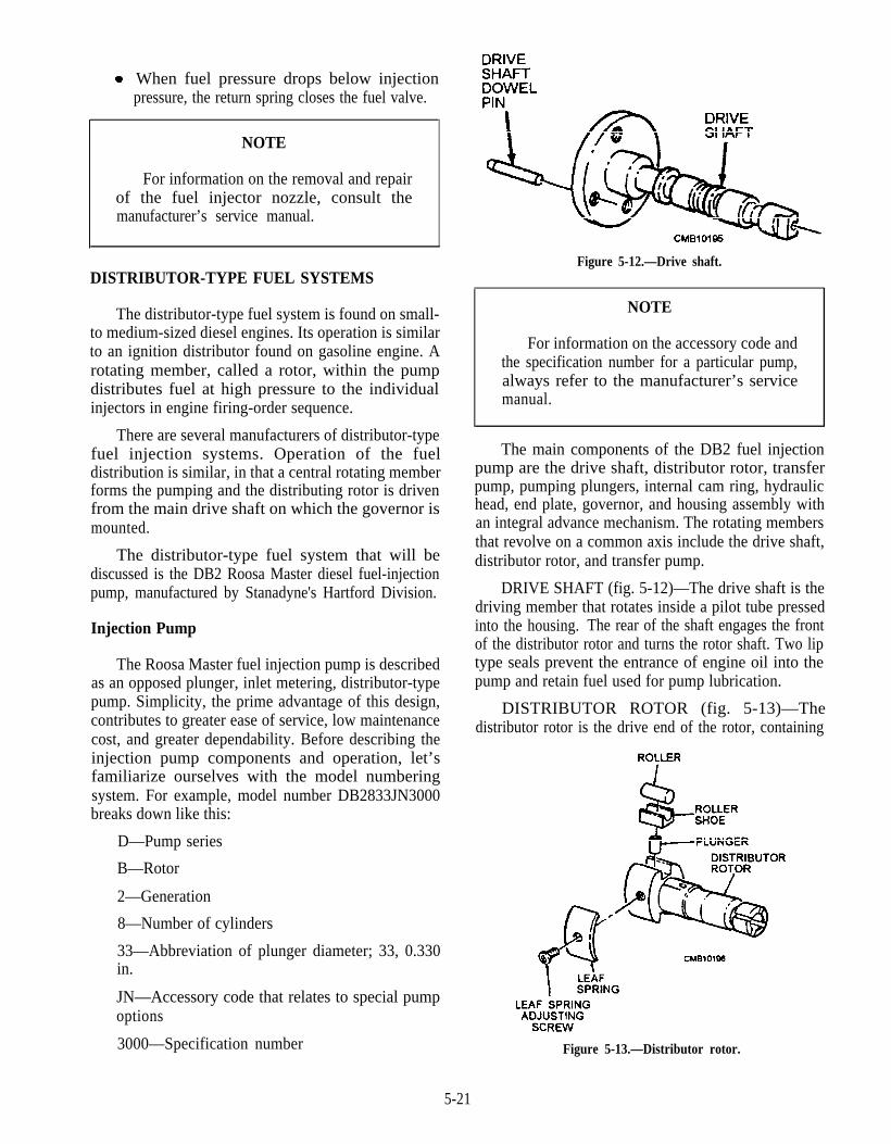
When fuel pressure drops below injectionpressure, the return spring closes the fuel valve.
NOTE
For information on the removal and repairof the fuel injector nozzle, consult themanufacturer’s service manual.
DISTRIBUTOR-TYPE FUEL SYSTEMS
The distributor-type fuel system is found on small-to medium-sized diesel engines. Its operation is similarto an ignition distributor found on gasoline engine. Arotating member, called a rotor, within the pumpdistributes fuel at high pressure to the individualinjectors in engine firing-order sequence.
There are several manufacturers of distributor-typefuel injection systems. Operation of the fueldistribution is similar, in that a central rotating memberforms the pumping and the distributing rotor is drivenfrom the main drive shaft on which the governor ismounted.
The distributor-type fuel system that will bediscussed is the DB2 Roosa Master diesel fuel-injectionpump, manufactured by Stanadyne's Hartford Division.
Injection Pump
The Roosa Master fuel injection pump is describedas an opposed plunger, inlet metering, distributor-typepump. Simplicity, the prime advantage of this design,contributes to greater ease of service, low maintenancecost, and greater dependability. Before describing theinjection pump components and operation, let’sfamiliarize ourselves with the model numberingsystem. For example, model number DB2833JN3000breaks down like this:
D—Pump series
B—Rotor
2—Generation
8—Number of cylinders
33—Abbreviation of plunger diameter; 33, 0.330in.
JN—Accessory code that relates to special pumpoptions
3000—Specification number
Figure 5-12.—Drive shaft.
NOTE
For information on the accessory code andthe specification number for a particular pump,always refer to the manufacturer’s servicemanual.
The main components of the DB2 fuel injectionpump are the drive shaft, distributor rotor, transferpump, pumping plungers, internal cam ring, hydraulichead, end plate, governor, and housing assembly withan integral advance mechanism. The rotating membersthat revolve on a common axis include the drive shaft,distributor rotor, and transfer pump.
DRIVE SHAFT (fig. 5-12)—The drive shaft is thedriving member that rotates inside a pilot tube pressedinto the housing. The rear of the shaft engages the frontof the distributor rotor and turns the rotor shaft. Two liptype seals prevent the entrance of engine oil into thepump and retain fuel used for pump lubrication.
DISTRIBUTOR ROTOR (fig. 5-13)—Thedistributor rotor is the drive end of the rotor, containing
Figure 5-13.—Distributor rotor.
5-21
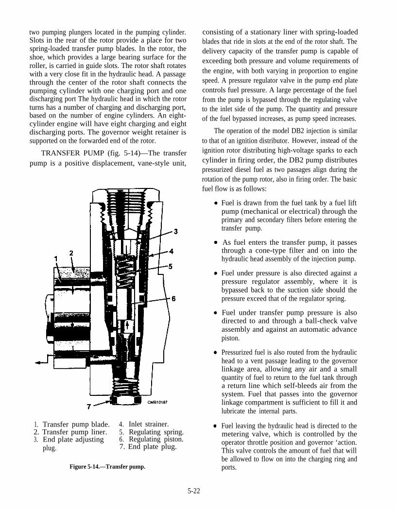
two pumping plungers located in the pumping cylinder.Slots in the rear of the rotor provide a place for twospring-loaded transfer pump blades. In the rotor, theshoe, which provides a large bearing surface for theroller, is carried in guide slots. The rotor shaft rotateswith a very close fit in the hydraulic head. A passagethrough the center of the rotor shaft connects thepumping cylinder with one charging port and onedischarging port The hydraulic head in which the rotorturns has a number of charging and discharging port,based on the number of engine cylinders. An eight-cylinder engine will have eight charging and eightdischarging ports. The governor weight retainer issupported on the forwarded end of the rotor.
TRANSFER PUMP (fig. 5-14)—The transferpump is a positive displacement, vane-style unit,
1. Transfer blade.pump 4. Inlet strainer.2. Transfer pump liner. 5.3. End plate adjusting
Regulating spring.6. Regulating piston.
plug. 7. End plate plug.
Figure 5-14.—Transfer pump.
consisting of a stationary liner with spring-loadedblades that ride in slots at the end of the rotor shaft. Thedelivery capacity of the transfer pump is capable ofexceeding both pressure and volume requirements ofthe engine, with both varying in proportion to enginespeed. A pressure regulator valve in the pump end platecontrols fuel pressure. A large percentage of the fuelfrom the pump is bypassed through the regulating valveto the inlet side of the pump. The quantity and pressureof the fuel bypassed increases, as pump speed increases.
The operation of the model DB2 injection is similarto that of an ignition distributor. However, instead of theignition rotor distributing high-voltage sparks to eachcylinder in firing order, the DB2 pump distributespressurized diesel fuel as two passages align during therotation of the pump rotor, also in firing order. The basicfuel flow is as follows:
Fuel is drawn from the fuel tank by a fuel liftpump (mechanical or electrical) through theprimary and secondary filters before entering thetransfer pump.
As fuel enters the transfer pump, it passesthrough a cone-type filter and on into thehydraulic head assembly of the injection pump.
Fuel under pressure is also directed against apressure regulator assembly, where it isbypassed back to the suction side should thepressure exceed that of the regulator spring.
Fuel under transfer pump pressure is alsodirected to and through a ball-check valveassembly and against an automatic advancepiston.
Pressurized fuel is also routed from the hydraulichead to a vent passage leading to the governorlinkage area, allowing any air and a smallquantity of fuel to return to the fuel tank througha return line which self-bleeds air from thesystem. Fuel that passes into the governorlinkage compartment is sufficient to fill it andlubricate the internal parts.
Fuel leaving the hydraulic head is directed to themetering valve, which is controlled by theoperator throttle position and governor ‘action.This valve controls the amount of fuel that willbe allowed to flow on into the charging ring andports.
5-22
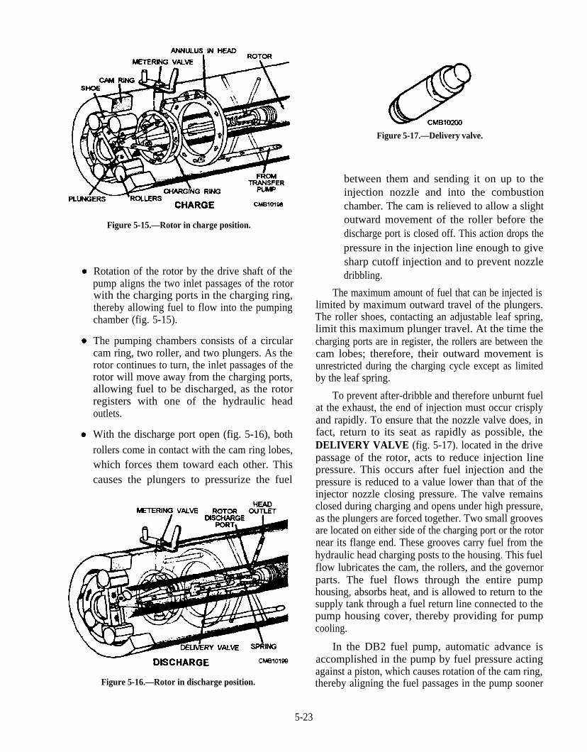
Figure 5-15.—Rotor in charge position.
Rotation of the rotor by the drive shaft of thepump aligns the two inlet passages of the rotorwith the charging ports in the charging ring,thereby allowing fuel to flow into the pumpingchamber (fig. 5-15).
The pumping chambers consists of a circularcam ring, two roller, and two plungers. As therotor continues to turn, the inlet passages of therotor will move away from the charging ports,allowing fuel to be discharged, as the rotorregisters with one of the hydraulic headoutlets.
With the discharge port open (fig. 5-16), both
rollers come in contact with the cam ring lobes,which forces them toward each other. Thiscauses the plungers to pressurize the fuel
Figure 5-16.—Rotor in discharge position.
Figure 5-17.—Delivery valve.
between them and sending it on up to theinjection nozzle and into the combustionchamber. The cam is relieved to allow a slightoutward movement of the roller before thedischarge port is closed off. This action drops thepressure in the injection line enough to givesharp cutoff injection and to prevent nozzledribbling.
The maximum amount of fuel that can be injected islimited by maximum outward travel of the plungers.The roller shoes, contacting an adjustable leaf spring,limit this maximum plunger travel. At the time thecharging ports are in register, the rollers are between thecam lobes; therefore, their outward movement isunrestricted during the charging cycle except as limitedby the leaf spring.
To prevent after-dribble and therefore unburnt fuelat the exhaust, the end of injection must occur crisplyand rapidly. To ensure that the nozzle valve does, infact, return to its seat as rapidly as possible, theDELIVERY VALVE (fig. 5-17). located in the drivepassage of the rotor, acts to reduce injection linepressure. This occurs after fuel injection and thepressure is reduced to a value lower than that of theinjector nozzle closing pressure. The valve remainsclosed during charging and opens under high pressure,as the plungers are forced together. Two small groovesare located on either side of the charging port or the rotornear its flange end. These grooves carry fuel from thehydraulic head charging posts to the housing. This fuelflow lubricates the cam, the rollers, and the governorparts. The fuel flows through the entire pumphousing, absorbs heat, and is allowed to return to thesupply tank through a fuel return line connected to thepump housing cover, thereby providing for pumpcooling.
In the DB2 fuel pump, automatic advance isaccomplished in the pump by fuel pressure actingagainst a piston, which causes rotation of the cam ring,thereby aligning the fuel passages in the pump sooner
5-23
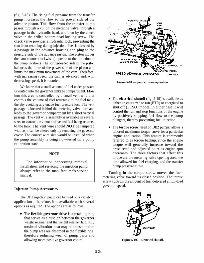
(fig. 5-18). The rising fuel pressure from the transferpump increases the flow to the power side of theadvance piston. This flow from the transfer pumppasses through a cut on the metering valve, through apassage in the hydraulic head, and then by the checkvalve in the drilled bottom head locking screw. Thecheck valve provides a hydraulic lock, preventing thecam from retarding during injection. Fuel is directed bya passage in the advance housing and plug to thepressure side of the advance piston. The piston movesthe cam counterclockwise (opposite to the direction ofthe pump rotation). The spring-loaded side of the pistonbalances the force of the power side of the piston andlimits the maximum movement of the cam. Therefore,with increasing speed, the cam is advanced and, withdecreasing speed, it is retarded.
We know that a small amount of fuel under pressureis vented into the governor linkage compartment. Flowinto this area is controlled by a small vent wire thatcontrols the volume of fuel returning to the fuel tank,thereby avoiding any undue fuel pressure loss. The ventpassage is located behind the metering valve bore andleads to the governor compartment by a short verticalpassage. The vent wire assembly is available in severalsizes to control the amount of vented fuel being returnedto the tank. The vent wire should NOT be tamperedwith, as it can be altered only by removing the governorcover. The correct wire size would be installed whenthe pump assembly is being flow-tested on a pumpcalibration stand.
NOTE
For information concerning removal,installation, and servicing the injection pump,always refer to the manufacturer’s servicemanual.
Injection Pump Accessories
The DB2 injection pump can be used on a variety ofapplications; therefore, it is available with severaloptions as required. The options are as follows:
The flexible governor drive is a retaining ringthat serves as a cushion between the governorweight retainer and the weight retainer hub. Anytorsional vibrations that may be transmitted tothe pump area are absorbed in the flexible ring,therefore reducing wear of pump parts andallowing more positive governor control.
Figure 5-18.—Speed advance operation.
The electrical shutoff (fig. 5-19) is available aseither an energized to run (ETR) or energized toshut off (ETSO) model. In either case it willcontrol the run and stop functions of the engineby positively stopping fuel flow to the pumpplungers, thereby preventing fuel injection.
The torque screw, used on DB2 pumps, allows atailored maximum torque curve for a particularengine application. This feature is commonlyreferred to as torque backup, since the enginetorque will generally increase toward thepreselected and adjusted point as engine rpmdecreases. The three factors that affect thistorque are the metering valve opening area, thetime allowed for fuel charging, and the transferpump pressure curve.
Turning in the torque screw moves the fuel-metering valve toward its closed position. The torquescrew controls the amount of fuel delivered at full-loadgovernor speed.
Figure 5-19.—Electrical shutoff.
5-24
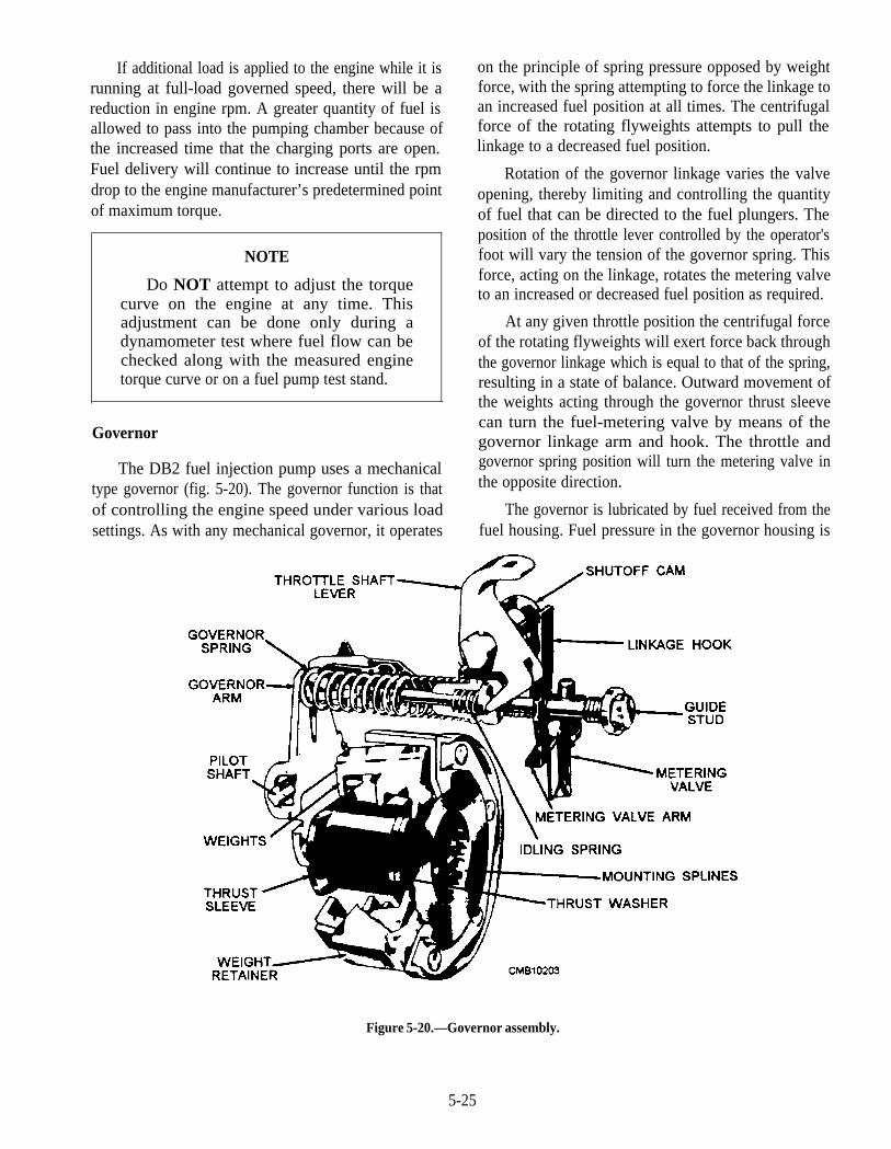
If additional load is applied to the engine while it isrunning at full-load governed speed, there will be areduction in engine rpm. A greater quantity of fuel isallowed to pass into the pumping chamber because ofthe increased time that the charging ports are open.Fuel delivery will continue to increase until the rpmdrop to the engine manufacturer’s predetermined pointof maximum torque.
NOTE
Do NOT attempt to adjust the torquecurve on the engine at any time. Thisadjustment can be done only during adynamometer test where fuel flow can bechecked along with the measured enginetorque curve or on a fuel pump test stand.
Governor
The DB2 fuel injection pump uses a mechanicaltype governor (fig. 5-20). The governor function is thatof controlling the engine speed under various loadsettings. As with any mechanical governor, it operates
on the principle of spring pressure opposed by weightforce, with the spring attempting to force the linkage toan increased fuel position at all times. The centrifugalforce of the rotating flyweights attempts to pull thelinkage to a decreased fuel position.
Rotation of the governor linkage varies the valveopening, thereby limiting and controlling the quantityof fuel that can be directed to the fuel plungers. Theposition of the throttle lever controlled by the operator'sfoot will vary the tension of the governor spring. Thisforce, acting on the linkage, rotates the metering valveto an increased or decreased fuel position as required.
At any given throttle position the centrifugal forceof the rotating flyweights will exert force back throughthe governor linkage which is equal to that of the spring,resulting in a state of balance. Outward movement ofthe weights acting through the governor thrust sleevecan turn the fuel-metering valve by means of thegovernor linkage arm and hook. The throttle andgovernor spring position will turn the metering valve inthe opposite direction.
The governor is lubricated by fuel received from thefuel housing. Fuel pressure in the governor housing is
Figure 5-20.—Governor assembly.
5-25
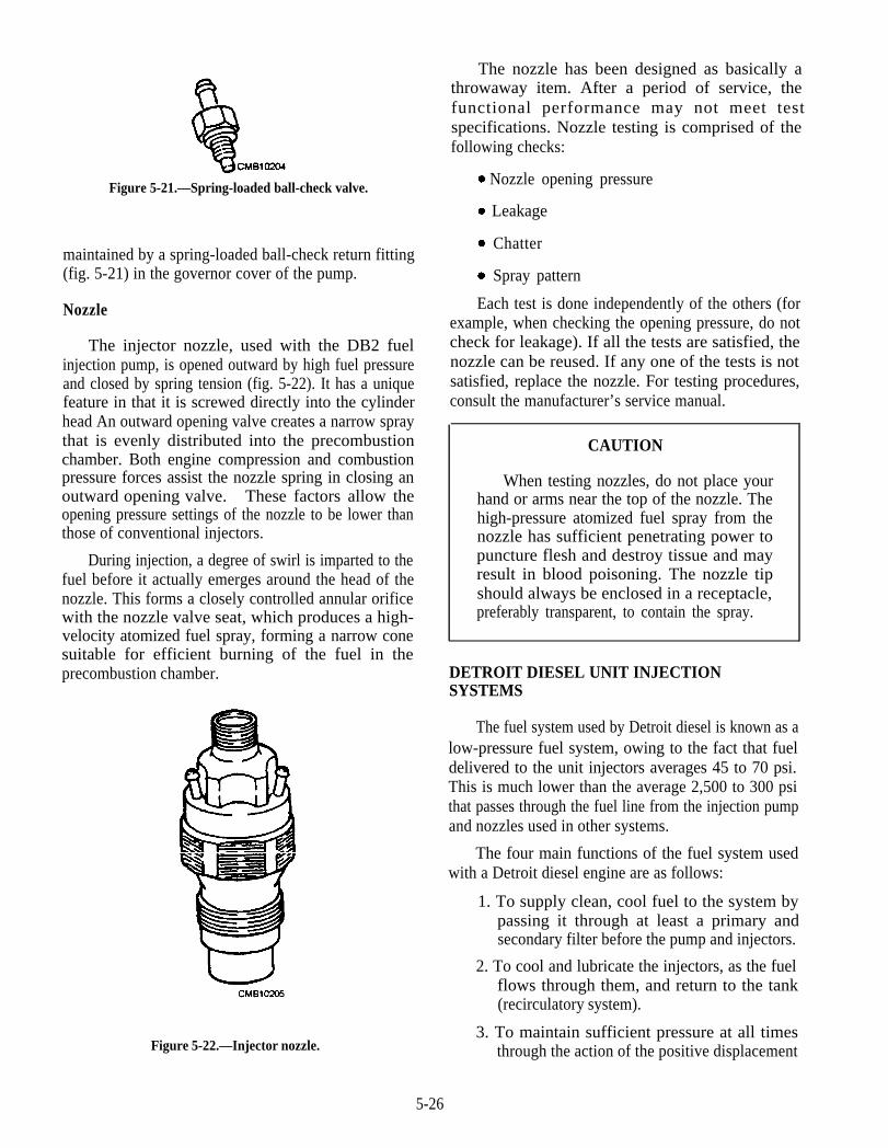
Figure 5-21.—Spring-loaded ball-check valve.
maintained by a spring-loaded ball-check return fitting(fig. 5-21) in the governor cover of the pump.
Nozzle
The injector nozzle, used with the DB2 fuelinjection pump, is opened outward by high fuel pressureand closed by spring tension (fig. 5-22). It has a uniquefeature in that it is screwed directly into the cylinderhead An outward opening valve creates a narrow spraythat is evenly distributed into the precombustionchamber. Both engine compression and combustionpressure forces assist the nozzle spring in closing anoutward opening valve. These factors allow theopening pressure settings of the nozzle to be lower thanthose of conventional injectors.
During injection, a degree of swirl is imparted to thefuel before it actually emerges around the head of thenozzle. This forms a closely controlled annular orificewith the nozzle valve seat, which produces a high-velocity atomized fuel spray, forming a narrow conesuitable for efficient burning of the fuel in theprecombustion chamber.
Figure 5-22.—Injector nozzle.
The nozzle has been designed as basically athrowaway item. After a period of service, thefunctional performance may not meet testspecifications. Nozzle testing is comprised of thefollowing checks:
Nozzle opening pressure
Leakage
Chatter
Spray pattern
Each test is done independently of the others (forexample, when checking the opening pressure, do notcheck for leakage). If all the tests are satisfied, thenozzle can be reused. If any one of the tests is notsatisfied, replace the nozzle. For testing procedures,consult the manufacturer’s service manual.
CAUTION
When testing nozzles, do not place yourhand or arms near the top of the nozzle. Thehigh-pressure atomized fuel spray from thenozzle has sufficient penetrating power topuncture flesh and destroy tissue and mayresult in blood poisoning. The nozzle tipshould always be enclosed in a receptacle,preferably transparent, to contain the spray.
DETROIT DIESEL UNIT INJECTIONSYSTEMS
The fuel system used by Detroit diesel is known as alow-pressure fuel system, owing to the fact that fueldelivered to the unit injectors averages 45 to 70 psi.This is much lower than the average 2,500 to 300 psithat passes through the fuel line from the injection pumpand nozzles used in other systems.
The four main functions of the fuel system usedwith a Detroit diesel engine are as follows:
1. To supply clean, cool fuel to the system bypassing it through at least a primary andsecondary filter before the pump and injectors.
2. To cool and lubricate the injectors, as the fuelflows through them, and return to the tank(recirculatory system).
3. To maintain sufficient pressure at all timesthrough the action of the positive displacement
5-26
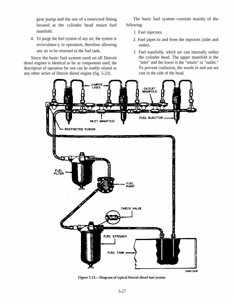
gear pump and the use of a restricted fittinglocated at the cylinder head return fuelmanifold.
4. To purge the fuel system of any air; the system isrecirculator-y in operation, therefore allowingany air to be returned to the fuel tank.
Since the basic fuel system used on all Detroitdiesel engines is identical as far as components used, thedescription of operation for one can be readily related toany other series of Detroit diesel engine (fig. 5-23).
The basic fuel system consists mainly of thefollowing:
1. Fuel injectors.
2. Fuel pipes to and from the injectors (inlet andoutlet).
3. Fuel manifolds, which are cast internally withinthe cylinder head. The upper manifold is the"inlet" and the lower is the "return" or "outlet."To prevent confusion, the words in and out arecast in the side of the head.
Figure 5-23.—Diagram of typical Detroit diesel fuel system.
5-27
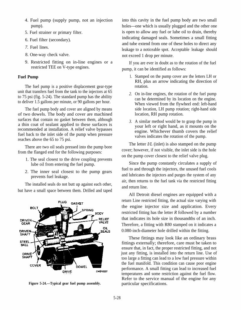
4. Fuel pump (supply pump, not an injectionpump).
5. Fuel strainer or primary filter.
6. Fuel filter (secondary).
7. Fuel lines.
8. One-way check valve.
9. Restricted fitting on in-line engines or arestricted TEE on V-type engines.
Fuel Pump
The fuel pump is a positive displacement gear-typeunit that transfers fuel from the tank to the injectors at 65to 75 psi (fig. 5-24). The standard pump has the abilityto deliver 1.5 gallons per minute, or 90 gallons per hour.
The fuel pump body and cover are aligned by meansof two dowels. The body and cover are machinedsurfaces that contain no gasket between them, althougha thin coat of sealant applied to these surfaces isrecommended at installation. A relief valve bypassesfuel back to the inlet side of the pump when pressurereaches above the 65 to 75 psi.
There are two oil seals pressed into the pump borefrom the flanged end for the following purposes:
1. The seal closest to the drive coupling preventslube oil from entering the fuel pump.
2. The inner seal closest to the pump gearsprevents fuel leakage.
The installed seals do not butt up against each other,but have a small space between them. Drilled and taped
Figure 5-24.—Typical gear fuel pump assembly.
into this cavity in the fuel pump body are two smallholes—one which is usually plugged and the other oneis open to allow any fuel or lube oil to drain, therebyindicating damaged seals. Sometimes a small fittingand tube extend from one of these holes to direct anyleakage to a noticeable spot. Acceptable leakage shouldnot exceed 1 drop per minute.
If you are ever in doubt as to the rotation of the fuelpump, it can be identified as follows:
1.
2.
3.
Stamped on the pump cover are the letters LH orRH, plus an arrow indicating the direction ofrotation.
On in-line engines, the rotation of the fuel pumpcan be determined by its location on the engine.When viewed from the flywheel end: left-handside location, LH pump rotation; right-hand sidelocation, RH pump rotation.
A similar method would be to grasp the pump inyour left or right hand, as it mounts on theengine. Whichever thumb covers the reliefvalves indicates the rotation of the pump.
The letter I/L (inlet) is also stamped on the pumpcover; however, if not visible, the inlet side is the holeon the pump cover closest to the relief valve plug.
Since the pump constantly circulates a supply offuel to and through the injectors, the unused fuel coolsand lubricates the injectors and purges the system of anyair, then returns to the fuel tank via the restricted fittingand return line.
All Detroit diesel engines are equipped with areturn Line restricted fitting, the actual size varying withthe engine injector size and application. Everyrestricted fitting has the letter R followed by a numberthat indicates its hole size in thousandths of an inch.Therefore, a fitting with R80 stamped on it indicates a0.080-inch-diameter hole drilled within the fitting.
These fittings may look like an ordinary brassfittings externally; therefore, care must be taken toensure that, in fact, the proper restricted fitting, and notjust any fitting, is installed into the return line. Use oftoo large a fitting can lead to a low fuel pressure withinthe fuel manifold. This condition can cause poor engineperformance. A small fitting can lead to increased fueltemperatures and some restriction against the fuel flow.Refer to the service manual of the engine for anyparticular specifications.
5-28
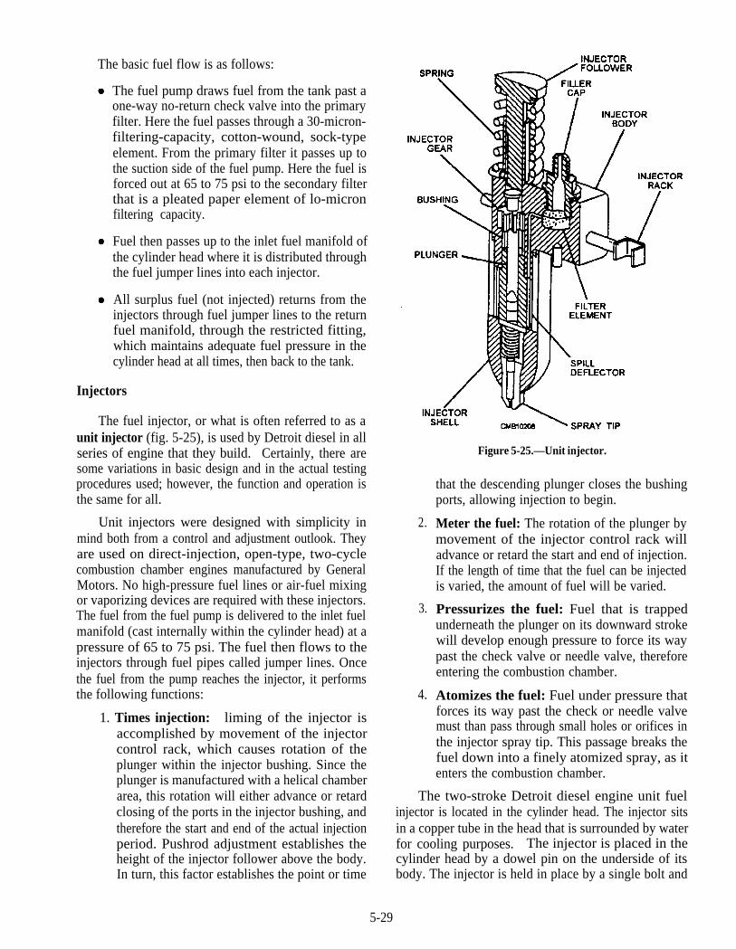
The basic fuel flow is as follows:
The fuel pump draws fuel from the tank past aone-way no-return check valve into the primaryfilter. Here the fuel passes through a 30-micron-filtering-capacity, cotton-wound, sock-typeelement. From the primary filter it passes up tothe suction side of the fuel pump. Here the fuel isforced out at 65 to 75 psi to the secondary filterthat is a pleated paper element of lo-micronfiltering capacity.
Fuel then passes up to the inlet fuel manifold ofthe cylinder head where it is distributed throughthe fuel jumper lines into each injector.
All surplus fuel (not injected) returns from theinjectors through fuel jumper lines to the returnfuel manifold, through the restricted fitting,which maintains adequate fuel pressure in thecylinder head at all times, then back to the tank.
Injectors
The fuel injector, or what is often referred to as aunit injector (fig. 5-25), is used by Detroit diesel in allseries of engine that they build. Certainly, there aresome variations in basic design and in the actual testingprocedures used; however, the function and operation isthe same for all.
Unit injectors were designed with simplicity inmind both from a control and adjustment outlook. Theyare used on direct-injection, open-type, two-cyclecombustion chamber engines manufactured by GeneralMotors. No high-pressure fuel lines or air-fuel mixingor vaporizing devices are required with these injectors.The fuel from the fuel pump is delivered to the inlet fuelmanifold (cast internally within the cylinder head) at apressure of 65 to 75 psi. The fuel then flows to theinjectors through fuel pipes called jumper lines. Oncethe fuel from the pump reaches the injector, it performsthe following functions:
1. Times injection: liming of the injector isaccomplished by movement of the injectorcontrol rack, which causes rotation of theplunger within the injector bushing. Since theplunger is manufactured with a helical chamberarea, this rotation will either advance or retardclosing of the ports in the injector bushing, andtherefore the start and end of the actual injectionperiod. Pushrod adjustment establishes theheight of the injector follower above the body.In turn, this factor establishes the point or time
2.
3.
4.
Figure 5-25.—Unit injector.
that the descending plunger closes the bushingports, allowing injection to begin.
Meter the fuel: The rotation of the plunger bymovement of the injector control rack willadvance or retard the start and end of injection.If the length of time that the fuel can be injectedis varied, the amount of fuel will be varied.
Pressurizes the fuel: Fuel that is trappedunderneath the plunger on its downward strokewill develop enough pressure to force its waypast the check valve or needle valve, thereforeentering the combustion chamber.
Atomizes the fuel: Fuel under pressure thatforces its way past the check or needle valvemust than pass through small holes or orifices inthe injector spray tip. This passage breaks thefuel down into a finely atomized spray, as itenters the combustion chamber.
The two-stroke Detroit diesel engine unit fuelinjector is located in the cylinder head. The injector sitsin a copper tube in the head that is surrounded by waterfor cooling purposes. The injector is placed in thecylinder head by a dowel pin on the underside of itsbody. The injector is held in place by a single bolt and
5-29
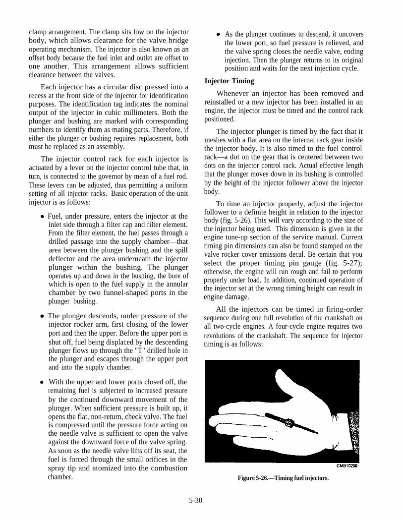
clamp arrangement. The clamp sits low on the injectorbody, which allows clearance for the valve bridgeoperating mechanism. The injector is also known as anoffset body because the fuel inlet and outlet are offset toone another. This arrangement allows sufficientclearance between the valves.
Each injector has a circular disc pressed into arecess at the front side of the injector for identificationpurposes. The identification tag indicates the nominaloutput of the injector in cubic millimeters. Both theplunger and bushing are marked with correspondingnumbers to identify them as mating parts. Therefore, ifeither the plunger or bushing requires replacement, bothmust be replaced as an assembly.
The injector control rack for each injector isactuated by a lever on the injector control tube that, inturn, is connected to the governor by mean of a fuel rod.These levers can be adjusted, thus permitting a uniformsetting of all injector racks. Basic operation of the unitinjector is as follows:
Fuel, under pressure, enters the injector at theinlet side through a filter cap and filter element.From the filter element, the fuel passes through adrilled passage into the supply chamber—thatarea between the plunger bushing and the spilldeflector and the area underneath the injectorplunger within the bushing. The plungeroperates up and down in the bushing, the bore ofwhich is open to the fuel supply in the annularchamber by two funnel-shaped ports in theplunger bushing.
The plunger descends, under pressure of theinjector rocker arm, first closing of the lowerport and then the upper. Before the upper port isshut off, fuel being displaced by the descendingplunger flows up through the "T" drilled hole inthe plunger and escapes through the upper portand into the supply chamber.
With the upper and lower ports closed off, theremaining fuel is subjected to increased pressureby the continued downward movement of theplunger. When sufficient pressure is built up, itopens the flat, non-return, check valve. The fuelis compressed until the pressure force acting onthe needle valve is sufficient to open the valveagainst the downward force of the valve spring.As soon as the needle valve lifts off its seat, thefuel is forced through the small orifices in thespray tip and atomized into the combustionchamber.
As the plunger continues to descend, it uncoversthe lower port, so fuel pressure is relieved, andthe valve spring closes the needle valve, endinginjection. Then the plunger returns to its originalposition and waits for the next injection cycle.
Injector Timing
Whenever an injector has been removed andreinstalled or a new injector has been installed in anengine, the injector must be timed and the control rackpositioned.
The injector plunger is timed by the fact that itmeshes with a flat area on the internal rack gear insidethe injector body. It is also timed to the fuel controlrack—a dot on the gear that is centered between twodots on the injector control rack. Actual effective lengththat the plunger moves down in its bushing is controlledby the height of the injector follower above the injectorbody.
To time an injector properly, adjust the injectorfollower to a definite height in relation to the injectorbody (fig. 5-26). This will vary according to the size ofthe injector being used. This dimension is given in theengine tune-up section of the service manual. Currenttiming pin dimensions can also be found stamped on thevalve rocker cover emissions decal. Be certain that youselect the proper timing pin gauge (fig. 5-27);otherwise, the engine will run rough and fail to performproperly under load. In addition, continued operation ofthe injector set at the wrong timing height can result inengine damage.
All the injectors can be timed in firing-ordersequence during one full revolution of the crankshaft onall two-cycle engines. A four-cycle engine requires tworevolutions of the crankshaft. The sequence for injectortiming is as follows:
Figure 5-26.—Timing fuel injectors.
5-30
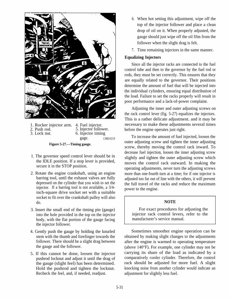
1. Rocker injector arm. 4. Fuel injector.2. Push rod. 5. Injector follower.3. Lock nut. 6. Injector timing
gage. CMB10210
Figure 5-27.—Timing gauge.
1. The governor speed control lever should be inthe IDLE position. If a stop lever is provided,secure it in the STOP position.
2. Rotate the engine crankshaft, using an enginebarring tool, until the exhaust valves are fullydepressed on the cylinder that you wish to set theinjector. If a barring tool is not available, a 3/4-inch-square drive socket set with a suitablesocket to fit over the crankshaft pulley will alsodo.
3. Insert the small end of the timing pin (gauge)into the hole provided in the top on the injectorbody, with the flat portion of the gauge facingthe injector follower.
4. Gently push the gauge by holding the knurledstem with the thumb and forefinger towards thefollower. There should be a slight drag betweenthe gauge and the follower.
5. If this cannot be done, loosen the injectorpushrod locknut and adjust it until the drag ofthe gauge (slight feel) has been determined.Hold the pushrod and tighten the locknut.Recheck the feel, and, if needed, readjust.
6.
7.
When hot setting this adjustment, wipe off thetop of the injector follower and place a cleandrop of oil on it. When properly adjusted, thegauge should just wipe off the oil film from thefollower when the slight drag is felt.
Time remaining injectors in the same manner.
Equalizing Injectors
Since all the injector racks are connected to the fuelcontrol tube and then to the governor by the fuel rod orrods, they must be set correctly. This ensures that theyare equally related to the governor. Their positionsdetermine the amount of fuel that will be injected intothe individual cylinders, ensuring equal distribution ofthe load. Failure to set the racks properly will result inpoor performance and a lack-of-power complaint.
Adjusting the inner and outer adjusting screws onthe rack control lever (fig. 5-27) equalizes the injectors.This is a rather delicate adjustment. and it may benecessary to make these adjustments several timesbefore the engine operates just right.
To increase the amount of fuel injected, loosen theouter adjusting screw and tighten the inner adjustingscrew, thereby moving the control rack inward. Todecrease fuel injection, loosen the inner adjusting screwslightly and tighten the outer adjusting screw whichmoves the control rack outward. In making theoperating adjustments, never turn the adjusting screwsmore than one-fourth turn at a time; for if one injector isadjusted too far out of line with the others, it will preventthe full travel of the racks and reduce the maximumpower to the engine.
NOTE
For exact procedures for adjusting theinjector rack control levers, refer to themanufacturer’s service manual.
Sometimes smoother engine operation can beobtained by making slight changes to the adjustmentsafter the engine is warmed to operating temperature(above 140°F). For example, one cylinder may not becarrying its share of the load as indicated by acomparatively cooler cylinder. Therefore, the controlrack should be adjusted for more fuel. A slightknocking noise from another cylinder would indicate anadjustment for slightly less fuel.
5-31
Do not attempt to obtain a smooth running engineby changing control-rack settings without first timingand equalizing injection in the recommended manner.
Governor
Detroit diesel engines use both mechanical andhydraulic governors on the engines of the followingtype:
1.
2.
3.
Mechanical limiting speed governor
Variable mechanical speed governor
Variable low-speed limiting speed mechanicalgovernor
4. Mechanical constant speed governor (earlierengines)
5. Dual-range limiting speed mechanical governor
6. Woodward SG hydraulic governor
7. Woodward PSG hydraulic governor
8. Woodward electric governor
On Detroit diesel engines the type of governor usedis dependent on the particular engine application;therefore, setup can vary slightly between engines. AllDetroit diesel mechanical governors are easilyidentifiable by a nameplate attached to the governorhousing. The following letters are typical examples.
DWLS: double-weight limiting speed (mobileequipment)
SWLS: single-weight limiting speed (mobileequipment)
Regardless of whether the limiting speed governoris of the single- or double-weight variety, the action ofthe governor is the same. The purpose of the limitingspeed governor is as follows:
1. Controls engine idle speed
2. Limits the maximum speed of the engine
The application of the engine determines whether asingle- or double-weight governor will be used. Themost prominent application for the limiting speedgovernor is highway truck engines, since the governorhas no control in the intermediate engine speed range.This allows the operator to have complete control of theinjector rack movement through throttle action alone.This permits fast throttle response for engineacceleration or deceleration.
SWVS: single-weight variable speed (industrialand marine)
VLSLS: variable low-speed limiting speed(highway vehicles)
DWDRG: double-weight dual range governor(highway vehicles)
The variable speed mechanical governor is foundextensively on industrial and marine applications, sinceit is designed for the following functions:
1. Controls the engine idle speed
2. Controls the maximum engine speed
SG, PSG, SGX, UG8: Woodward hydraulic-typegovernors (industrial and generator sets)
3. Holds the engine speed at any position betweenidle and maximum as desired and set by theoperator.
The functions of all these governors, whethermechanical or hydraulic, are to control engine speedand correct for any change in load applied or removedfrom the engine. They all work on the basic principle ofweights against spring pressure; therefore, allgovernors are of the speed-sensing type.
The response and reaction of the variable speedmechanical governor is similar to that of the limitingspeed type with just a few exceptions. Since the varia-ble speed mechanical governor controls speed through-out the total rpm range, there is no intermediate range aswith the limiting speed governor. The variable speedgovernor uses only one set of weights and one spring.
Since the action of all these governors is the same, In a variable speed mechanical governor, any givenbut with a difference only in purpose, we will discuss throttle setting or load from idle to maximum speed, a
the two most common types found on a Detroit dieselengine—the limiting and variable speed governors.
The limiting speed type governor is found in bothsingle- and double-weight version and can also befound on both in-line and V-type engines. Riveted onthe side of the governor housing is an identificationplate, which shows the following:
1.
2.
3.
4.
5.
Governor part number
Date of manufacture
Idle speed range
Type, such as DWLS, meaning double-weightlimiting speed
Drive ratio
5-32
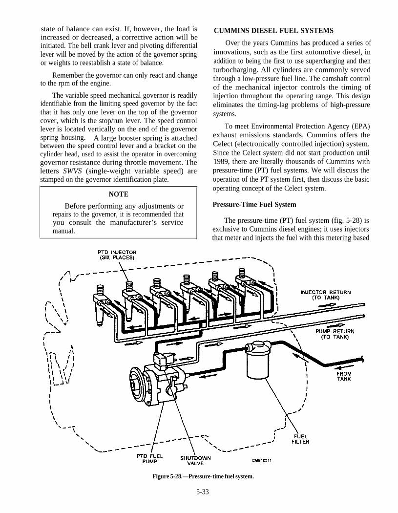
state of balance can exist. If, however, the load isincreased or decreased, a corrective action will beinitiated. The bell crank lever and pivoting differentiallever will be moved by the action of the governor springor weights to reestablish a state of balance.
Remember the governor can only react and changeto the rpm of the engine.
The variable speed mechanical governor is readilyidentifiable from the limiting speed governor by the factthat it has only one lever on the top of the governorcover, which is the stop/run lever. The speed controllever is located vertically on the end of the governorspring housing. A large booster spring is attachedbetween the speed control lever and a bracket on thecylinder head, used to assist the operator in overcominggovernor resistance during throttle movement. Theletters SWVS (single-weight variable speed) arestamped on the governor identification plate.
NOTE
Before performing any adjustments orrepairs to the governor, it is recommended thatyou consult the manufacturer’s servicemanual.
Figure 5-28.—Pressure-time fuel system.
5-33
CUMMINS DIESEL FUEL SYSTEMS
Over the years Cummins has produced a series ofinnovations, such as the first automotive diesel, inaddition to being the first to use supercharging and thenturbocharging. All cylinders are commonly servedthrough a low-pressure fuel line. The camshaft controlof the mechanical injector controls the timing ofinjection throughout the operating range. This designeliminates the timing-lag problems of high-pressuresystems.
To meet Environmental Protection Agency (EPA)exhaust emissions standards, Cummins offers theCelect (electronically controlled injection) system.Since the Celect system did not start production until1989, there are literally thousands of Cummins withpressure-time (PT) fuel systems. We will discuss theoperation of the PT system first, then discuss the basicoperating concept of the Celect system.
Pressure-Time Fuel System
The pressure-time (PT) fuel system (fig. 5-28) isexclusive to Cummins diesel engines; it uses injectorsthat meter and injects the fuel with this metering based
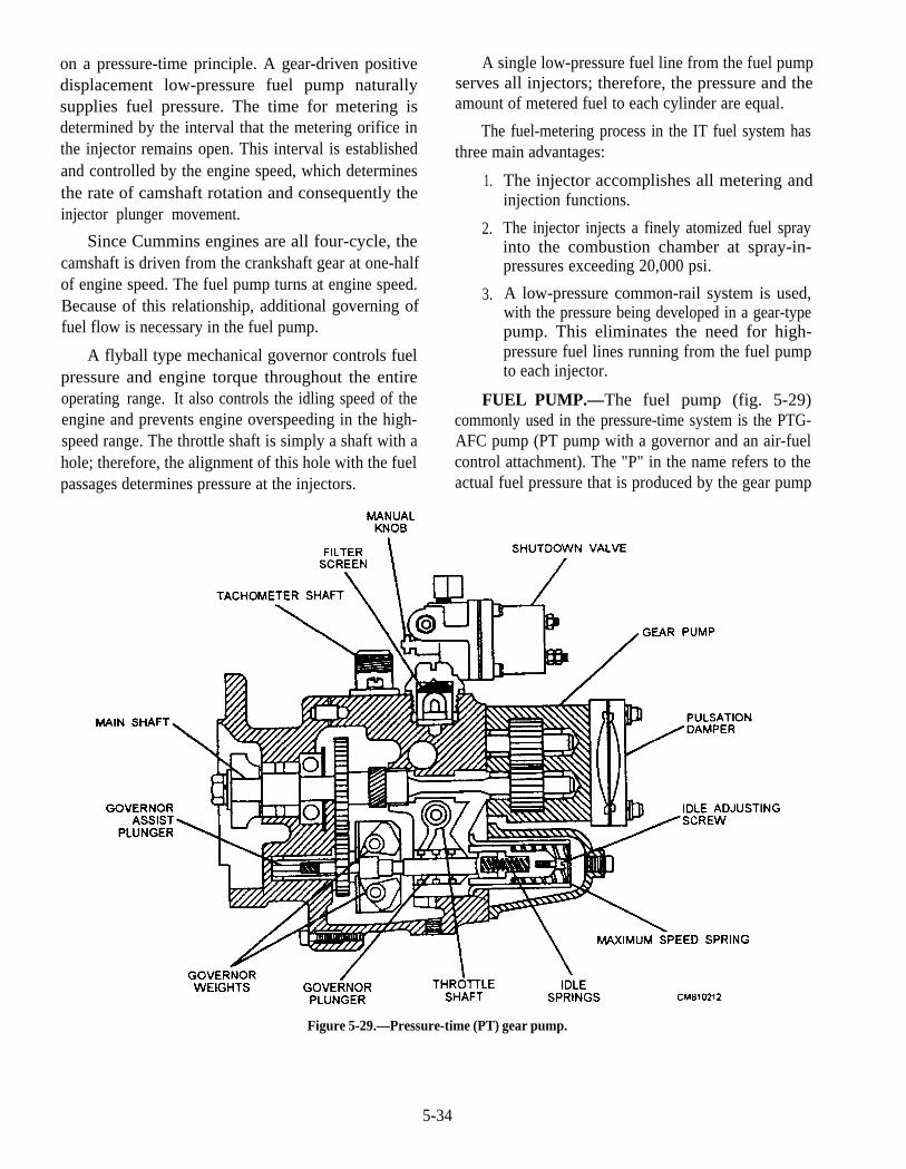
on a pressure-time principle. A gear-driven positivedisplacement low-pressure fuel pump naturallysupplies fuel pressure. The time for metering isdetermined by the interval that the metering orifice inthe injector remains open. This interval is establishedand controlled by the engine speed, which determinesthe rate of camshaft rotation and consequently theinjector plunger movement.
Since Cummins engines are all four-cycle, thecamshaft is driven from the crankshaft gear at one-halfof engine speed. The fuel pump turns at engine speed.Because of this relationship, additional governing offuel flow is necessary in the fuel pump.
A flyball type mechanical governor controls fuelpressure and engine torque throughout the entireoperating range. It also controls the idling speed of theengine and prevents engine overspeeding in the high-speed range. The throttle shaft is simply a shaft with ahole; therefore, the alignment of this hole with the fuelpassages determines pressure at the injectors.
A single low-pressure fuel line from the fuel pumpserves all injectors; therefore, the pressure and theamount of metered fuel to each cylinder are equal.
The fuel-metering process in the IT fuel system hasthree main advantages:
1.
2.
3.
The injector accomplishes all metering andinjection functions.
The injector injects a finely atomized fuel sprayinto the combustion chamber at spray-in-pressures exceeding 20,000 psi.
A low-pressure common-rail system is used,with the pressure being developed in a gear-typepump. This eliminates the need for high-pressure fuel lines running from the fuel pumpto each injector.
FUEL PUMP.—The fuel pump (fig. 5-29)commonly used in the pressure-time system is the PTG-AFC pump (PT pump with a governor and an air-fuelcontrol attachment). The "P" in the name refers to theactual fuel pressure that is produced by the gear pump
Figure 5-29.—Pressure-time (PT) gear pump.
5-34

and maintained at the inlet to the injectors. The "T"refers to the fact that the actual "time" available for thefuel to flow into the injector assembly (cup) isdetermined by the engine speed as a function of theengine camshaft and injection train components.
The air-fuel control (AFC) is an accelerationexhaust smoke control device built internally into thepump body. The AFC unit is designed to restrict fuelflow in direct proportion to the air intake manifoldpressure of the engine during acceleration, under load,and during lug-down conditions.
Within the pump assembly a fuel pump bypassbutton of varying sizes can be installed to control themaximum fuel delivery pressure of the gear-type pumpbefore it opens and bypasses fuel back to the inlet side ofthe pump. In this way the horsepower setting of theengine can be altered fairly easily. The major functionsof the PTG-AFC fuel pump assembly are as follows:
1. To pull and transfer fuel from the tank and filter
2. To develop sufficient fuel pressure to the fuelrail (common fuel passage) to all of the injectors
3. To provide engine idle speed control(governing)
4. To limit the maximum no-load and full-loadspeed of the engine (governing)
5. To allow the operator to control the throttleposition and therefore the power output of theengine
6. To control exhaust smoke emissions to EPAspecifications under all operating conditions
7. To allow shutdown of the engine when desired
A major feature of the PT pump system is that thereis no need to time the pump to the engine. The pump isdesigned simply to generate and supply a given flowrate at a specified pressure setting to the rail to allinjectors. The injectors themselves are timed to ensurethat the start of injection will occur at the right time foreach cylinder.
The basic flow of fuel into and through the PT pumpassembly will vary slightly depending on the actualmodel. A simplified fuel flow is as follows:
As the operator cranks the engine, fuel is drawnfrom the fuel tank by the gear pump through the
fuel supply line to the primary filter. This filter isnormally a filter/water separator.
The filter fuel then flows through a small filterscreen that is located within the PT pumpassembly, and then flows down into the internalgovernor sleeve.
The position of the governor plunger determinesthe fuel flow through various governor plungerports.
The position of the mechanically operatedthrottle determines the amount of fuel that canflow through the throttle shaft.
Fuel from the throttle shaft is then directed to theAFC needle valve.
The position of the AFC control plunger withinthe AFC barrel determines how much throttlefuel can flow into and through the AFC unit andon to the engine fuel rail, which feeds the fuelrail.
The AFC plunger position is determined by theamount of turbocharger boost pressure in the intakemanifold, which is piped through the air passage fromthe intake manifold to the AFC unit. At engine start-up,the boost pressure is very low; therefore, flow is limited.Fuel under pressure flows through the electric solenoidvalve, which is energized by power from the ignitionswitch. This fuel then flows through the fuel railpressure line and into the injectors.
A percentage of the fuel from both the PT pump andthe injectors is routed back to the fuel tank in order tocarry away some of the heat that was picked up coolingand lubricating the internal components of the pumpand the injectors.
INJECTORS.—A PT injector is provided at eachengine cylinder to spray the fuel into the combustionchambers. PT injectors are of the unit type and areoperated mechanically by a plunger return spring and arocker arm mechanism operating off the camshaft.There are four phases of injector operation, which are asfollows:
5-35

Metering (fig. 5-30)—The plunger is justbeginning to move downward and the engine ison the beginning of the compression stroke. Thefuel is trapped in the cup, the check ball stops thefuel flowing backwards, and fuel begins to bepressurized. The excess fuel flows around thelower annular ring, up the barrel, and is trappedthere.
Pre-injection (fig. 5-30)—The plunger isalmost all the way down, the engine is almost atthe end of the compression stroke, and the fuel isbeing pressurized by the plunger.
Injection (fig. 5-30)—The plunger is almost allthe way down, the fuel injected out the eightorifices, and the engine is on the end of thecompression stroke.
Purging (fig. 5-30)—The plunger is all the waydown, injection is complete, and the fuel isflowing into the injector, around the lowerannular groove, up a drilled passageway in thebarrel, around the upper annular groove, and outthrough the fuel drain. The cylinder is on thepower stroke. During the exhaust stroke, theplunger moves up and waits to begin the cycle allover.
Injector adjustments are extremely important on PTinjectors because they perform the dual functions ofmetering and injecting. Check the manufacturer’smanual for proper settings of injectors. On an enginewhere new or rebuilt injectors have been installed,initial adjustments can be made with the engine cold.Always readjust the injectors, using a torque wrenchcalibrated in inch-pounds after the engine has beenwarmed up. Engine oil temperature should readbetween 140°F and 160°F.
Anytime an injector is serviced, you must be certainthat the correct orifices, plungers, and cups are used, asthese can affect injection operation. You can also affectinjection operation by any of the following actions:
Improper timing.
Mixing plungers and barrels during teardown(keep them together, since they are matchedsets).
Incorrect injector adjustments after installationor during tune-up adjustment.
Installing an exchange set of injectors withouttaking time to check and correct other possibleproblems relating to injection operation. This isoften overlooked.
Proper injector adjustment and maintenance willensure a smooth running engine as long as the followingfactors are met:
1. Adequate fuel delivery pressure from the fuelpump to the fuel manifold.
2. Selection of the proper sizes of balance andmetering orifices.
3. The length of time that the metering orifice isuncovered by the upward moving injectorplunger.
NOTE
F o r r e q u i r e d a d j u s t m e n t s a n dmaintenance schedules, always consult themanufacturer’s service manual.
Celect System
The Celect system is a full electronic controlledinjection and governing system. The major reasonbehind the adoption of electronic fuel injection controlis to be able to meet not only the EPA (EnvironmentalProtection Agency) exhaust emission controls but alsoensure optimum fuel economy. This is done byconstantly monitoring major engine operatingparameters that have a direct bearing on enginecombustion efficiency. A number of engine- andvehicle-mounted sensors are used to update timing andmetering values continually. The Celect systemcontrols the following major operating factors:
1. Engine torque and horsepower curves
2. AFC (air-fuel control) to limit exhaust smoke
3. Engine low idle and high speeds
4. Functions as a vehicle road speed governor
5. Optional vehicle/engine cruise control
6. PTO (power takeoff) operation
7. Idle shutdown, 3 to 60 seconds
8. Gear down protection
For the Celect system to operate, major componentsare required. These components are as follows:
5-36
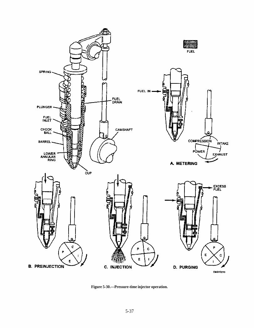
Figure 5-30.—Pressure-time injector operation.
5-37
1.
2.
3.
4.
The electronic control module (ECM) containsthe hardware required to activate the ECIsystem. Within the ECM are such controls asthe EPROM (elec t r ica l ly erasableprogrammable read-only memory), CPU(central processing unit), RAM (randomaccess memory), and also contain in the ECMis the A/D (analog/digital) converter. TheECM sends electrical signals to the injectors,engine brake solenoids, the fuel shutoff valve,and other optional items. The ECM is mountedto a cooling plate which has diesel fuelcontinually routed through it from the pump inorder to keep the internal solid-statecomponents at a safe operating temperature.
The engine position sensor (EPS) is required totell the ECM where the various pistons are andwhat stroke they are on, so the correct injectorsolenoid can be activated at the right time.
The oil temperature sensor (OTS) is used toadvise the ECM of the oil temperature. Thesignal is used by the ECM to determine theengine idle speed at start-up as well as reducingthe fueling rate any time the oil temperaturerises to an undesirable level.
The oil pressure sensor (OPS) is used by theECM to monitor engine oil pressure duringoperation.
5. The coolant temperature sensor (CTS) is used tomonitor the temperature of the engine coolant.
6. The coolant level sensor (CLS) is used to tellthe ECM of a coolant level loss.
7. The ambient air pressure sensor (APS) is usedby the ECM to determine the basic operatingaltitude of the vehicle.
8. The intake manifold temperature sensor(IMTS) allows the ECM to determine airtemperature and adjust fuel rate accordingly.
9. The throttle position sensor (TPS) is basically apotentiometer or variable resistor arrangementthat is designed to a output voltage signal to theECM, based on the degree of the throttle pedaldepression. The ECM is able to determine howmuch fuel the operator is asking for.
10. The vehicle speed sensor (VSS) is required totell the ECM the road speed of the vehicle. TheVSS sensor is mounted into the transmission
11.
output shaft housing in order to monitor theoutput shaft speed.
The electronically controlled injectors receivelow-pressure fuel from a simple engine-drivengear pump. Each injector is mechanicallyoperated; however, timing and duration ofinjection is controlled electronically by asignal from the ECM. This signal is referred toas pulse-width-modulated (PWM). The longerthe PWM signal is, the longer the injector willdeliver fuel to the combustion chamber. Thegreater the fuel delivery, the greater thehorsepower produced.
Two other major control switches are required withthe Celect-ECI system in order to control the cruisecontrol, the PTO (power takeoff), and the enginecompression brake:
1. A clutch switch is used to allow cruise controlor engine brake activation. It is mounted sothat when the clutch pedal is pushed down(clutch disengaged), the clutch switch opensthe switch and deactivates the engine brake orPTO.
2. A brake switch is located in the service air lineand will remain in the closed position any timethe brakes are released. Applying the brakeswill cause the brake switch to open and breakthe electrical circuit to both the cruise controland PTO systems.
In addition to the engine-mounted components,there are several cab-mounted controls arranged on asmall control panel that can be activated by the operatorthrough a series of small toggle-type switches. Thiscontrol panel contains the following:
The idle-speed adjustment switch is used toadjust the engine idle speed between 550 and 800rpm. Each time the switch is moved briefly to the+ or – position, the idle speed will change byapproximately 25 rpm.
The cruise control panel has two toggleswitches—one is a simple ON/OFF switch andthe other is the actual cruise control positionselect switch that the operator uses to set andadjust the cruise control speed during operation.
The engine brake panel has two toggleswitches—one switch has an ON/OFF positionto activate either a Jacobs or Cummins "C" brakesystem and the other switch, used with the engine
5-38
brake control, can be placed into position 1, 2, or3. In position 1 the compression brake isactivated only on two cylinders; position 2 willactivate the compression brake on fourcylinders; position 3 will allow all six cylindersto provide compression braking.
On the right-hand side of the control panel are twowarning lights—one yellow, the other one red. Theyellow light is labeled warning, while the red light islabeled stop. When the yellow light comes on duringengine operation, this indicates that a Celect systemproblem has been detected and recorded in the ECMmemory. The problem is not serious enough to shutdown the engine, but should be checked out at theearliest opportunity. If the red light comes on, theoperator should immediately bring the vehicle to a stopand shut off the engine.
Celect System Operation
The ECI (electronically controlled injection) Celectsystem uses an engine-driven gear pump to pull fuelfrom the fuel tank. The fuel is passed through a primaryfilter or filter/water separator unit, then to the ECMwhere the fuel is circulated through a cooling plate. Thecooling plate, mounted to the rear of-the ECM, ensuresadequate cooling of the electronic package.
The gear pump is designed to deliver fuel to the fuelmanifold at 140 psi, which supplies the electronicallycontrolled injectors. A spring-loaded bypass valveallows excess fuel under pressure to return to the suctionside of the pump to maintain maximum systempressure.
A rocker arm and pushrod assembly mechanicallyoperates the injector. The injector requires rocker armactuation of the plunger to create high fuel pressure forinjection. To control both the start of injection timingand the quantity of fuel metered, the ECM sends out apulse-width-modulated (PWM) electrical signal to eachinjector. The PWM signal determines the start ofinjection, while the duration of this signal determineshow long the injector can effectively continue to sprayfuel into the combustion chamber, as the plunger isforced down by the rocker arm assembly. A shorterPWM signal means that the effective stroke of theinjector plunger will be decreased. A longer PWMsignal means that the effective stroke will be increased.The start of injection and the duration of the PWMsignal is determined by the ECM, based on the variousinput sensor signals and the preprogrammed PROMinformation within the ECM. Each PROM is designed
for a specific engine/vehicle combination, based on thedesired horsepower setting and rpm, the tire size, andgear ratios used in the vehicle.
Contained within the injector are a timing plunger, areturn spring, and an injector control valve—that is thekey to the operation. The control valve is electricallyoperated, receiving signals from the ECM toenergize/de-energize, which determines the start ofinjection. The length of time that this solenoid isenergized determines the quantity of metered fuel to beinjected into the combustion chamber. Also within theinjector body is a metering spill port which must beclosed to allow injection, a metering piston, the biasspring, and the spill-timing port. The injectionsequence of events occur as follows:
1.
2.
3.
4.
The injector receives a signal from the ECM; theinjector control valve will close and themetering phase begins while the metering pistonand timing plunger are bottomed in the injector.
As the camshaft rotates, the injector pushrodcam follower will ride down the cam ramp,thereby allowing the rocker arm and pushrod tobe forced up by the energy of the timing plungerreturn spring. Fuel at gear pump pressure of 140psi can flow into the fuel supply passage andunseat the lower check valve, allowing themetering chamber to be charged withpressurized fuel as long as the timing plunger isbeing pulled upward by the force of the largeexternal spring. Fuel pressure, acting on thebottom of the metering piston, forces it tomaintain contact with the timing plunger withinthe bore of the injector body.
Metering ends when the ECM energizes theinjector control valve, causing it to open.Pressurized fuel can flow through the openinjector control valve into the upper timingchamber, which stops the upward travel of themetering piston. To ensure that the meteringpiston remains stationary, the small bias springin the timing chambers holds it in place, whilethe timing plunger continues upward due tocamshaft rotation. Fuel and spring pressure,acting on the metering piston, will ensure fuelpressure is maintained below the piston to keepthe lower metering ball-check valve closed.This allows a precisely metered quantity of fuelto be trapped in the metering chamber.
As long as the timing plunger moves upwarddue to the rotating camshaft lobe action and the
5-39
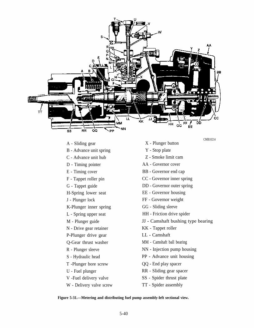
A - Sliding gear
B - Advance unit spring
C - Advance unit hub
D - Timing pointer
E - Timing cover
F - Tappet roller pin
G - Tappet guide
H-Spring lower seat
J - Plunger lock
K-Plunger inner spring
L - Spring upper seat
M - Plunger guide
N - Drive gear retainer
P-Plunger drive gear
Q-Gear thrust washer
R - Plunger sleeve
S - Hydraulic head
T -Plunger bore screw
U - Fuel plunger
V -Fuel delivery valve
W - Delivery valve screw
CMB10214X - Plunger button
Y - Stop plate
Z - Smoke limit cam
AA - Governor cover
BB - Governor end cap
CC - Governor inner spring
DD - Governor outer spring
EE - Governor housing
FF - Governor weight
GG - Sliding sleeve
HH - Friction drive spider
JJ - Camshaft bushing type bearing
KK - Tappet roller
LL - Camshaft
MM - Camshaft ball bearing
NN - Injection pump housing
PP - Advance unit housing
QQ - End play spacer
RR - Sliding gear spacer
SS - Spider thrust plate
TT - Spider assembly
Figure 5-31.—Metering and distributing fuel pump assembly-left sectional view.
5-40
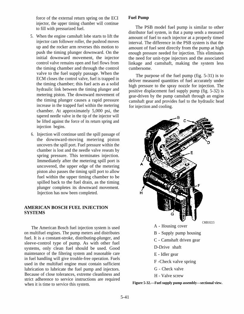
force of the external return spring on the ECIinjector, the upper timing chamber will continueto fill with pressurized fuel.
5. When the engine camshaft lobe starts to lift theinjector cam follower roller, the pushrod movesup and the rocker arm reverses this motion topush the timing plunger downward. On theinitial downward movement, the injectorcontrol valve remains open and fuel flows fromthe timing chamber and through the controlvalve to the fuel supply passage. When theECM closes the control valve, fuel is trapped inthe timing chamber; this fuel acts as a solidhydraulic link between the timing plunger andmetering piston. The downward movement ofthe timing plunger causes a rapid pressureincrease in the trapped fuel within the meteringchamber. At approximately 5,000 psi, thetapered needle valve in the tip of the injector willbe lifted against the force of its return spring andinjection begins.
6. Injection will continue until the spill passage ofthe downward-moving metering pistonuncovers the spill port. Fuel pressure within thechamber is lost and the needle valve reseats byspring pressure. This terminates injection.Immediately after the metering spill port isuncovered, the upper edge of the meteringpiston also passes the timing spill port to allowfuel within the upper timing chamber to bespilled back to the fuel drain, as the timingplunger completes its downward movement.Injection has now been completed.
AMERICAN BOSCH FUEL INJECTIONSYSTEMS
The American Bosch fuel injection system is usedon multifuel engines. The pump meters and distributesfuel. It is a constant-stroke, distributing-plunger, andsleeve-control type of pump. As with other fuelsystems, only clean fuel should be used. Goodmaintenance of the filtering system and reasonable carein fuel handling will give trouble-free operation. Fuelsused in the multifuel engine must contain sufficientlubrication to lubricate the fuel pump and injectors.Because of close tolerances, extreme cleanliness andstrict adherence to service instructions are requiredwhen it is time to service this system.
Fuel Pump
The PSB model fuel pump is similar to otherdistributor fuel system, in that a pump sends a measuredamount of fuel to each injector at a properly timedinterval. The difference in the PSB system is that theamount of fuel sent directly from the pump at highenough pressure needed for injection. This eliminatesthe need for unit-type injectors and the associatedlinkage and camshaft, making the system lesscumbersome.
The purpose of the fuel pump (fig. 5-31) is todeliver measured quantities of fuel accurately underhigh pressure to the spray nozzle for injection. Thepositive displacement fuel supply pump (fig. 5-32) isgear-driven by the pump camshaft through an enginecamshaft gear and provides fuel to the hydraulic headfor injection and cooling.
CMB10215A - Housing cover
B - Supply pump housing
C - Camshaft driven gear
D-Drive shaft
E - Idler gear
F -Check valve spring
G - Check valve
H - Valve screw
Figure 5-32.—Fuel supply pump assembly—sectional view.
5-41
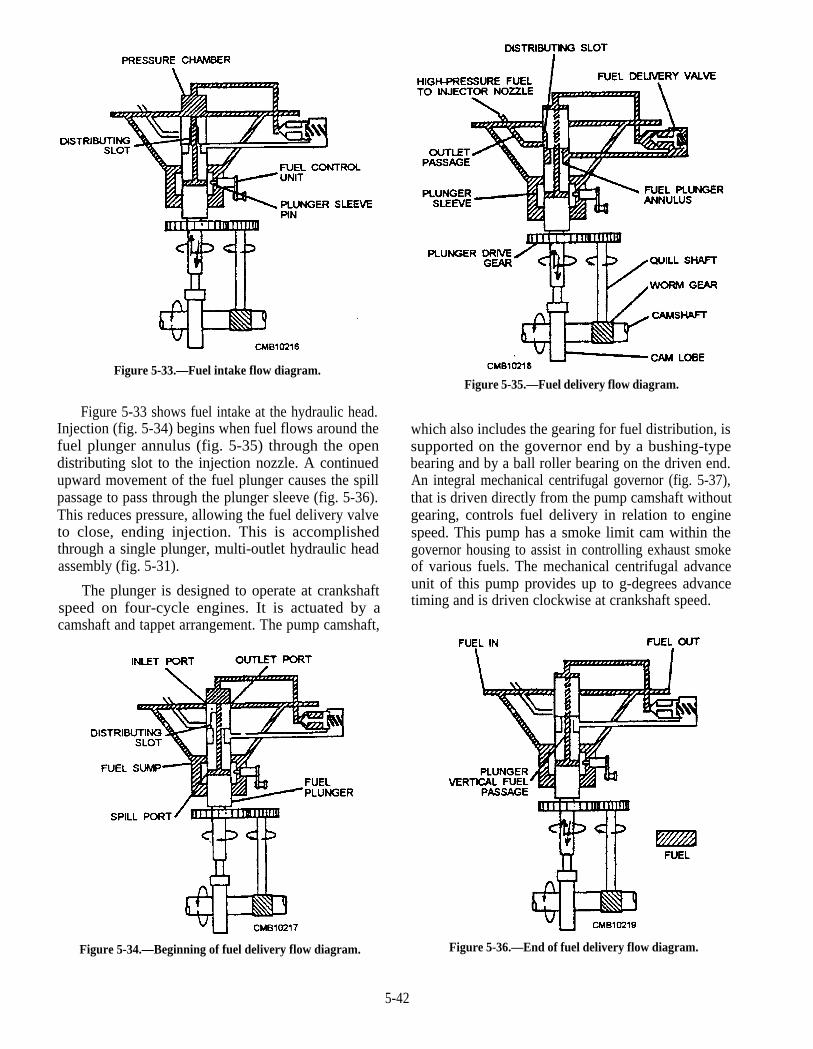
Figure 5-33.—Fuel intake flow diagram.
Figure 5-33 shows fuel intake at the hydraulic head.Injection (fig. 5-34) begins when fuel flows around thefuel plunger annulus (fig. 5-35) through the opendistributing slot to the injection nozzle. A continuedupward movement of the fuel plunger causes the spillpassage to pass through the plunger sleeve (fig. 5-36).This reduces pressure, allowing the fuel delivery valveto close, ending injection. This is accomplishedthrough a single plunger, multi-outlet hydraulic headassembly (fig. 5-31).
The plunger is designed to operate at crankshaftspeed on four-cycle engines. It is actuated by acamshaft and tappet arrangement. The pump camshaft,
Figure 5-35.—Fuel delivery flow diagram.
which also includes the gearing for fuel distribution, issupported on the governor end by a bushing-typebearing and by a ball roller bearing on the driven end.An integral mechanical centrifugal governor (fig. 5-37),that is driven directly from the pump camshaft withoutgearing, controls fuel delivery in relation to enginespeed. This pump has a smoke limit cam within thegovernor housing to assist in controlling exhaust smokeof various fuels. The mechanical centrifugal advanceunit of this pump provides up to g-degrees advancetiming and is driven clockwise at crankshaft speed.
Figure 5-34.—Beginning of fuel delivery flow diagram. Figure 5-36.—End of fuel delivery flow diagram.
5-42
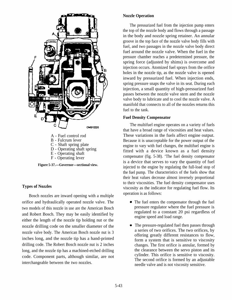
A - Fuel control rodB - Fulcrum leverC - Shaft spring plateD - Operating shaft springE - Operating shaftF - Operating lever
Figure 5-37.—Governor—sectional view.
Types of Nozzles
Bosch nozzles are inward opening with a multiple
orifice and hydraulically operated nozzle valve. Thetwo models of this nozzle in use are the American Boschand Robert Bosch. They may be easily identified byeither the length of the nozzle tip holding nut or thenozzle drilling code on the smaller diameter of thenozzle valve body. The American Bosch nozzle nut is 3inches long, and the nozzle tip has a hand-printeddrilling code. The Robert Bosch nozzle nut is 2 incheslong, and the nozzle tip has a machined-etched drillingcode. Component parts, although similar, are notinterchangeable between the two nozzles.
Nozzle Operation
The pressurized fuel from the injection pump entersthe top of the nozzle body and flows through a passagein the body and nozzle spring retainer. An annulargroove in the top face of the nozzle valve body fills withfuel, and two passages in the nozzle valve body directfuel around the nozzle valve. When the fuel in thepressure chamber reaches a predetermined pressure, thespring force (adjusted by shims) is overcome andinjection occurs. Atomized fuel sprays from the orificeholes in the nozzle tip, as the nozzle valve is openedinward by pressurized fuel. When injection ends,spring pressure snaps the valve in its seat. During eachinjection, a small quantity of high-pressurized fuelpasses between the nozzle valve stem and the nozzlevalve body to lubricate and to cool the nozzle valve. Amanifold that connects to all of the nozzles returns thisfuel to the tank.
Fuel Density Compensator
The multifuel engine operates on a variety of fuelsthat have a broad range of viscosities and heat values.These variations in the fuels affect engine output.Because it is unacceptable for the power output of theengine to vary with fuel changes, the multifuel engine isfitted with a device known as a fuel densitycompensator (fig. 5-38). ‘The fuel density compensatoris a device that serves to vary the quantity of fuelinjected to the engine by regulating the full-load stop ofthe fuel pump. The characteristics of the fuels show thattheir heat values decrease almost inversely proportionalto their viscosities. The fuel density compensator usesviscosity as the indicator for regulating fuel flow. Itsoperation is as follows:
The fuel enters the compensator through the fuelpressure regulator where the fuel pressure isregulated to a constant 20 psi regardless ofengine speed and load range.
The pressure-regulated fuel then passes througha series of two orifices. The two orifices, byoffering greatly different resistances to flow,form a system that is sensitive to viscositychanges. The first orifice is annular, formed bythe clearance between the servo piston and itscylinder. This orifice is sensitive to viscosity.The second orifice is formed by an adjustableneedle valve and is not viscosity sensitive.
5-43
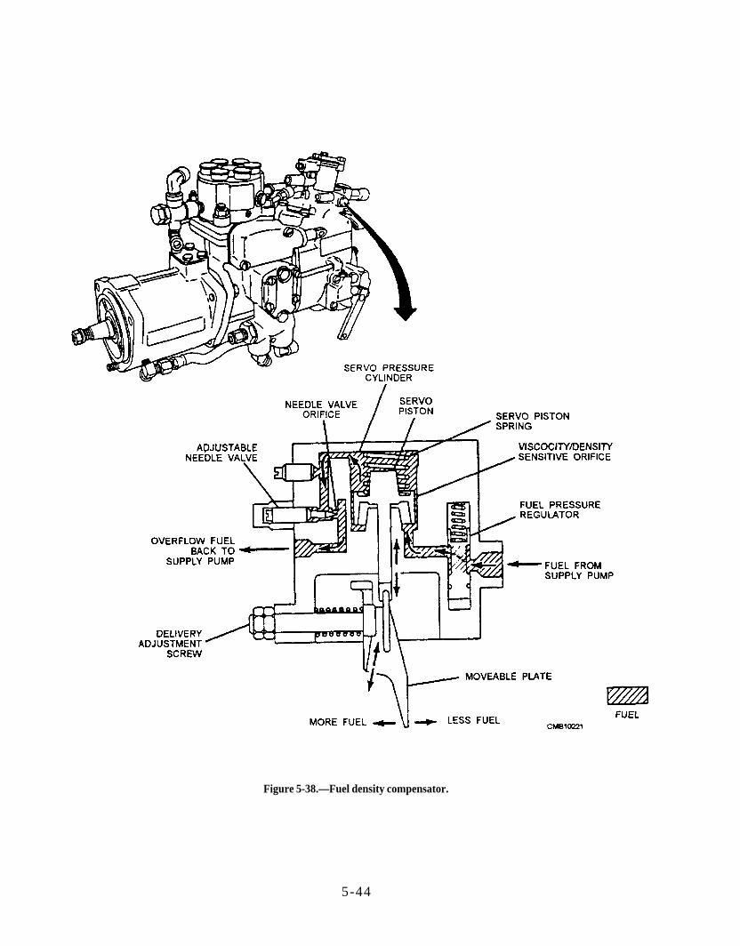
Figure 5-38.—Fuel density compensator.
5-44
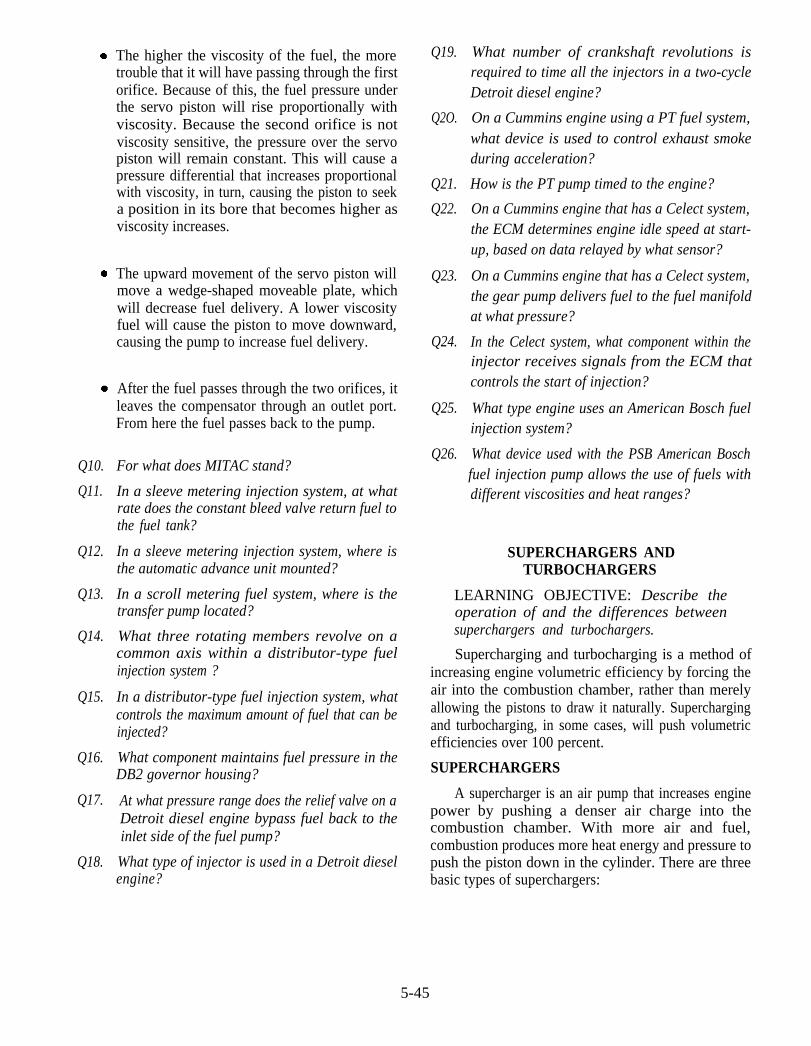
Q10.
Q11.
Q12.
Q13.
Q14.
Q15.
Q16.
Q17.
Q18.
The higher the viscosity of the fuel, the moretrouble that it will have passing through the firstorifice. Because of this, the fuel pressure underthe servo piston will rise proportionally withviscosity. Because the second orifice is notviscosity sensitive, the pressure over the servopiston will remain constant. This will cause apressure differential that increases proportionalwith viscosity, in turn, causing the piston to seeka position in its bore that becomes higher asviscosity increases.
The upward movement of the servo piston willmove a wedge-shaped moveable plate, whichwill decrease fuel delivery. A lower viscosityfuel will cause the piston to move downward,causing the pump to increase fuel delivery.
After the fuel passes through the two orifices, itleaves the compensator through an outlet port.From here the fuel passes back to the pump.
For what does MITAC stand?
In a sleeve metering injection system, at whatrate does the constant bleed valve return fuel tothe fuel tank?
In a sleeve metering injection system, where isthe automatic advance unit mounted?
In a scroll metering fuel system, where is thetransfer pump located?
What three rotating members revolve on acommon axis within a distributor-type fuelinjection system ?
In a distributor-type fuel injection system, whatcontrols the maximum amount of fuel that can beinjected?
What component maintains fuel pressure in theDB2 governor housing?
At what pressure range does the relief valve on aDetroit diesel engine bypass fuel back to theinlet side of the fuel pump?
What type of injector is used in a Detroit dieselengine?
Q19.
Q2O.
Q21.
Q22.
Q23.
Q24.
Q25.
Q26.
What number of crankshaft revolutions isrequired to time all the injectors in a two-cycleDetroit diesel engine?
On a Cummins engine using a PT fuel system,what device is used to control exhaust smokeduring acceleration?
How is the PT pump timed to the engine?
On a Cummins engine that has a Celect system,the ECM determines engine idle speed at start-up, based on data relayed by what sensor?
On a Cummins engine that has a Celect system,the gear pump delivers fuel to the fuel manifoldat what pressure?
In the Celect system, what component within theinjector receives signals from the ECM thatcontrols the start of injection?
What type engine uses an American Bosch fuelinjection system?
What device used with the PSB American Boschfuel injection pump allows the use of fuels withdifferent viscosities and heat ranges?
SUPERCHARGERS ANDTURBOCHARGERS
LEARNING OBJECTIVE: Describe theoperation of and the differences betweensuperchargers and turbochargers.
Supercharging and turbocharging is a method ofincreasing engine volumetric efficiency by forcing theair into the combustion chamber, rather than merelyallowing the pistons to draw it naturally. Superchargingand turbocharging, in some cases, will push volumetricefficiencies over 100 percent.
SUPERCHARGERS
A supercharger is an air pump that increases enginepower by pushing a denser air charge into thecombustion chamber. With more air and fuel,combustion produces more heat energy and pressure topush the piston down in the cylinder. There are threebasic types of superchargers:
5-45

1.
2.
3.
Centrifugal supercharger (fig. 5-39). Thecentrifugal supercharger has an impellerequipped with curved vanes. As the enginedrives the impeller, it draws air into its centerand throws it off at its rim. The air then ispushed along the inside of the circular housing.The diameter of the housing gradually increasesto the outlet where the air is pushed out.
Rotor (Rootes) supercharger (fig. 5-40). TheRootes supercharger is of the positivedisplacement type and consists of two rotorsinside a housing. As the engine drives therotors, air is trapped between them and thehousing. Air is then carried to the outlet where itis discharged. The rotors and the housing in thistype of supercharger must maintain tightclearances and therefore are sensitive to dirt.
Vane-type supercharger (fig. 5-41). The vane-type supercharger has an integral steel rotor andshaft, one end supported in the pump flange andthe other end in the cover, and revolves in thebody, the bore of which is eccentric to the rotor.Two sliding vanes are placed 180 degrees apartin slots in the rotor and are pressed against thebody bore by springs in the slots. When theshaft rotates, the vanes pick up a charge of air atthe inlet port, and it is carried around the body tothe outlet where the air is discharged. Pressureis produced by the wedging action of the air, as itis forced toward the outlet port by the vane.
Figure 5-39.—Centrifugal supercharger.
The term supercharger generally refers to a blowerdriven by a belt, chain, or gears. Superchargers are usedon large diesel and racing engines.
Figure 5-40.—Rootes supercharger.
5-46
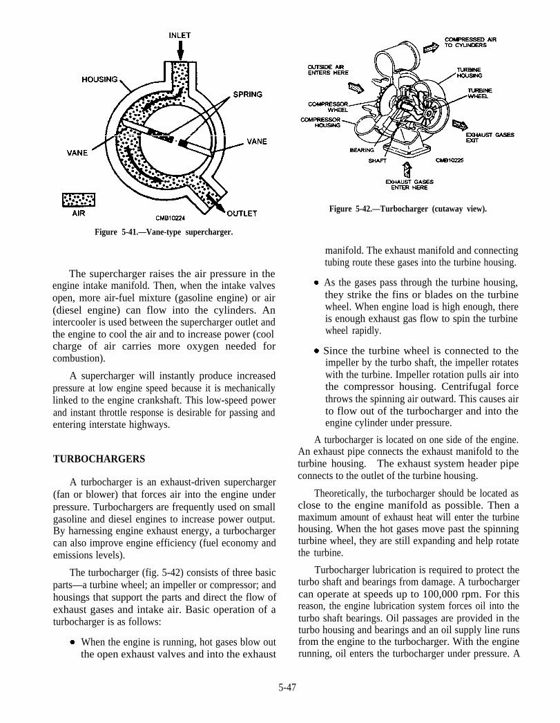
Figure 5-41.—Vane-type supercharger.
The supercharger raises the air pressure in theengine intake manifold. Then, when the intake valvesopen, more air-fuel mixture (gasoline engine) or air(diesel engine) can flow into the cylinders. Anintercooler is used between the supercharger outlet andthe engine to cool the air and to increase power (coolcharge of air carries more oxygen needed forcombustion).
A supercharger will instantly produce increasedpressure at low engine speed because it is mechanicallylinked to the engine crankshaft. This low-speed powerand instant throttle response is desirable for passing andentering interstate highways.
TURBOCHARGERS
A turbocharger is an exhaust-driven supercharger(fan or blower) that forces air into the engine underpressure. Turbochargers are frequently used on smallgasoline and diesel engines to increase power output.By harnessing engine exhaust energy, a turbochargercan also improve engine efficiency (fuel economy andemissions levels).
The turbocharger (fig. 5-42) consists of three basicparts—a turbine wheel; an impeller or compressor; andhousings that support the parts and direct the flow ofexhaust gases and intake air. Basic operation of aturbocharger is as follows:
When the engine is running, hot gases blow outthe open exhaust valves and into the exhaust
Figure 5-42.—Turbocharger (cutaway view).
manifold. The exhaust manifold and connectingtubing route these gases into the turbine housing.
As the gases pass through the turbine housing,they strike the fins or blades on the turbinewheel. When engine load is high enough, thereis enough exhaust gas flow to spin the turbinewheel rapidly.
Since the turbine wheel is connected to theimpeller by the turbo shaft, the impeller rotateswith the turbine. Impeller rotation pulls air intothe compressor housing. Centrifugal forcethrows the spinning air outward. This causes airto flow out of the turbocharger and into theengine cylinder under pressure.
A turbocharger is located on one side of the engine.An exhaust pipe connects the exhaust manifold to theturbine housing. The exhaust system header pipeconnects to the outlet of the turbine housing.
Theoretically, the turbocharger should be located asclose to the engine manifold as possible. Then amaximum amount of exhaust heat will enter the turbinehousing. When the hot gases move past the spinningturbine wheel, they are still expanding and help rotatethe turbine.
Turbocharger lubrication is required to protect theturbo shaft and bearings from damage. A turbochargercan operate at speeds up to 100,000 rpm. For thisreason, the engine lubrication system forces oil into theturbo shaft bearings. Oil passages are provided in theturbo housing and bearings and an oil supply line runsfrom the engine to the turbocharger. With the enginerunning, oil enters the turbocharger under pressure. A
5-47
drain passage and drain line allows oil to return to theengine oil pan after passing through the turbo bearings.
Sealing rings (piston-type rings) are placed aroundthe turbo shaft at each end of the turbo housing,preventing oil leakage into the compressor and turbinehousings.
Turbochargers require little maintenance betweenoverhauls if the air cleaners are serviced regularlyaccording to the manufacturer’s recommendations. Theturbocharger turbine requires periodic cleaning toremove carbon deposits that cause an unbalancedcondition at the high relative speeds at which the turbinemust rotate.
Turbocharging system problems usually show up asinadequate boost pressure (lack of engine power),leaking shaft seals (oil consumption), damaged turbineor impeller wheels (vibration and noise), or excessboost (detonation).
NOTE
Refer to a factory service manual for adetailed troubleshooting chart. It will list thecommon troubles for the particularturbocharging system.
There are several checks that can be made todetermine turbocharging system conditions. Thesechecks include the following:
Check connection of all vacuum lines to thewaste gate and oil lines to the turbocharger.
Use regulated, low-pressure air to check forwaste gate diaphragm leakage and operation.
Use a dash gauge or a test gauge to measure boostpressure. If needed connect the pressure gaugeto the intake manifold fitting. Compare to themanufacturer’s specifications.
Use a stethoscope to listen for bad turbochargerbearings.
Turbo Lag
Turbo lag refers to a short delay before theturbocharger develops sufficient boost (pressure aboveatmospheric pressure).
As the accelerator pedal is pressed down for rapidacceleration, the engine may lack power for a fewseconds. This is caused by the impeller and turbine
wheels not spinning fast enough. It takes time for theexhaust gases to bring the turbocharger up to operatingspeed. To minimize turbo lag, the turbine and impellerwheels are made very light so they can accelerate up torpm quickly.
Turbocharger Intercooler
A turbocharger intercooler is an air-to-air heatexchanger that cools the air entering the engine. It is aradiator-like device mounted at the pressure outlet ofthe turbocharger.
Outside air flows over and cools the fins and tubesof the intercooler. As the air flows through theintercooler, heat is removed. By cooling the air enteringthe engine, engine power is increased because the air ismore dense (contains more oxygen by volume).Cooling also reduces the tendency for enginedetonation.
Waste Gate
A waste gate limits the maximum amount of boostpressure developed by the turbocharger. It is a butterflyor poppet-type valve that allows exhaust to bypass theturbine wheel.
Without a waste gate, the turbocharger couldproduce too much pressure in the combustionchambers. This could lead to detonation (spontaneouscombustion) and engine damage.
A diaphragm assembly operates the waste gate.Intake manifold pressure acts on the diaphragm tocontrol waste gate valve action. The valve controls theopening and closing of a passage around the turbinewheel.
Under partial load, the system routes all of theexhaust gases through the turbine housing. The wastegate is closed by the diaphragm spring. This assuresthat there is adequate boost to increase power.
Under a full load, boost may become high enough toovercome spring pressure. Manifold pressurecompresses the spring and opens the waste gate. Thispermits some of the exhaust gases to flow through thewaste gate passage and into the exhaust system. Lessexhaust is left to spin the turbine. Boost pressure islimited to a preset value.
Q27. What device is used between the superchargeroutlet and the engine to cool the air?
Q28. In a turbocharger, what prevents oil from leakinginto the compressor and turbine housing?
5-48
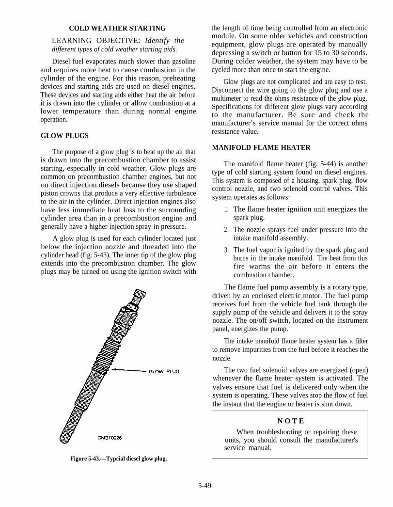
COLD WEATHER STARTING
LEARNING OBJECTIVE: Identify thedifferent types of cold weather starting aids.
Diesel fuel evaporates much slower than gasolineand requires more heat to cause combustion in thecylinder of the engine. For this reason, preheatingdevices and starting aids are used on diesel engines.These devices and starting aids either heat the air beforeit is drawn into the cylinder or allow combustion at alower temperature than during normal engineoperation.
GLOW PLUGS
The purpose of a glow plug is to beat up the air thatis drawn into the precombustion chamber to assiststarting, especially in cold weather. Glow plugs arecommon on precombustion chamber engines, but noton direct injection diesels because they use shapedpiston crowns that produce a very effective turbulenceto the air in the cylinder. Direct injection engines alsohave less immediate heat loss to the surroundingcylinder area than in a precombustion engine andgenerally have a higher injection spray-in pressure.
A glow plug is used for each cylinder located justbelow the injection nozzle and threaded into thecylinder head (fig. 5-43). The inner tip of the glow plugextends into the precombustion chamber. The glowplugs may be turned on using the ignition switch with
N O T E
When troubleshooting or repairing theseunits, you should consult the manufacturer'sservice manual.
Figure 5-43.—Typcial diesel glow plug.
the length of time being controlled from an electronicmodule. On some older vehicles and constructionequipment, glow plugs are operated by manuallydepressing a switch or button for 15 to 30 seconds.During colder weather, the system may have to becycled more than once to start the engine.
Glow plugs are not complicated and are easy to test.Disconnect the wire going to the glow plug and use amultimeter to read the ohms resistance of the glow plug.Specifications for different glow plugs vary accordingto the manufacturer. Be sure and check themanufacturer’s service manual for the correct ohmsresistance value.
MANIFOLD FLAME HEATER
The manifold flame heater (fig. 5-44) is anothertype of cold starting system found on diesel engines.This system is composed of a housing, spark plug, flowcontrol nozzle, and two solenoid control valves. Thissystem operates as follows:
1.
2.
3.
The flame heater ignition unit energizes thespark plug.
The nozzle sprays fuel under pressure into theintake manifold assembly.
The fuel vapor is ignited by the spark plug andburns in the intake manifold. The heat from thisfire warms the air before it enters thecombustion chamber.
The flame fuel pump assembly is a rotary type,driven by an enclosed electric motor. The fuel pumpreceives fuel from the vehicle fuel tank through thesupply pump of the vehicle and delivers it to the spraynozzle. The on/off switch, located on the instrumentpanel, energizes the pump.
The intake manifold flame heater system has a filterto remove impurities from the fuel before it reaches thenozzle.
The two fuel solenoid valves are energized (open)whenever the flame heater system is activated. Thevalves ensure that fuel is delivered only when thesystem is operating. These valves stop the flow of fuelthe instant that the engine or heater is shut down.
5-49
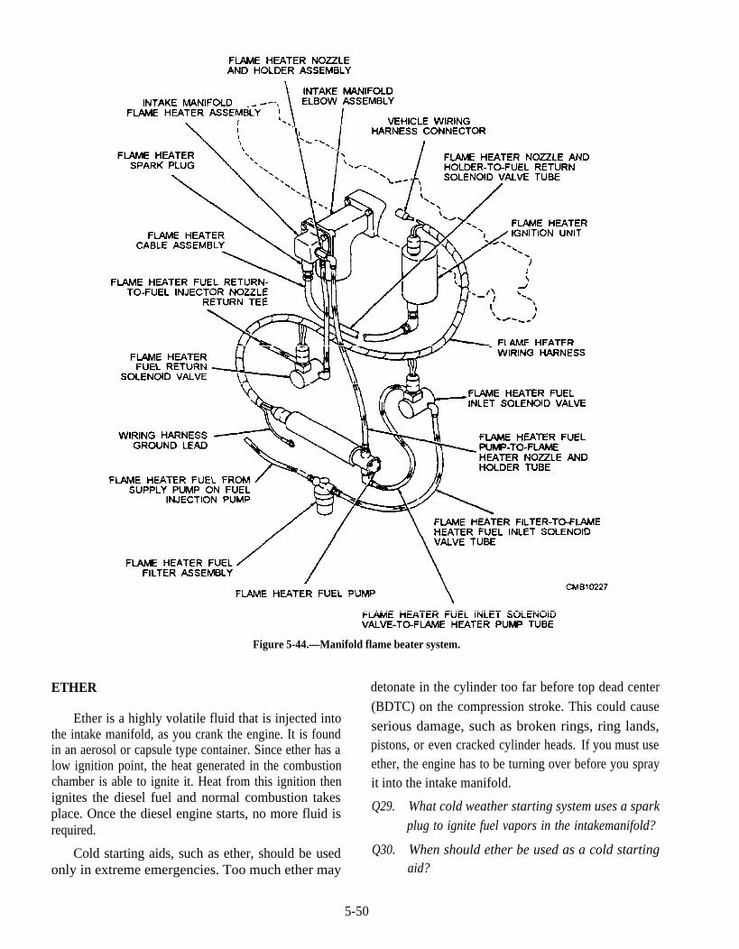
Figure 5-44.—Manifold flame beater system.
ETHER
Ether is a highly volatile fluid that is injected intothe intake manifold, as you crank the engine. It is foundin an aerosol or capsule type container. Since ether has alow ignition point, the heat generated in the combustionchamber is able to ignite it. Heat from this ignition thenignites the diesel fuel and normal combustion takesplace. Once the diesel engine starts, no more fluid isrequired.
Cold starting aids, such as ether, should be usedonly in extreme emergencies. Too much ether may
detonate in the cylinder too far before top dead center(BDTC) on the compression stroke. This could causeserious damage, such as broken rings, ring lands,pistons, or even cracked cylinder heads. If you must useether, the engine has to be turning over before you sprayit into the intake manifold.
Q29. What cold weather starting system uses a sparkplug to ignite fuel vapors in the intakemanifold?
Q30. When should ether be used as a cold startingaid?
5-50
DIESEL FUEL SYSTEMMAINTENANCE
LEARNING OBJECTIVE: Describe the basicmaintenance required for a diesel fuel system.
If all diesel engines had nearly identical fuel systemtrouble, diagnosis and maintenance procedures couldfollow a general pattern. But, with the exception ofsimilar fuel tanks and basic piping system, diesel fuelsystems differ considerably. Consequently, each enginemanufacturer recommends different specificmaintenance procedures. However, the tune-up andmaintenance procedures described are representative ofthe job you will do. For all jobs, refer to themanufacturer’s service manual for the fuel system youare servicing, even if you fully understand allprocedures.
DIRT IN FUEL SYSTEM
Many diesel engine operating troubles resultdirectly or indirectly from dirt in the fuel system. That iswhy proper fuel storage and handling are so important.One of the most important aspects of diesel fuel iscleanliness. The fuel should not contain more than atrace of foreign substance; otherwise, fuel pump andinjector troubles will occur. Diesel fuel, because it ismore viscous than gasoline, will hold dirt in suspensionfor longer periods. Therefore, every precaution shouldbe made to keep the fuel clean.
If the engine starts missing, running irregularly,rapping, or puffing black smoke from the exhaustmanifold, look for trouble at the spray nozzle valves. Inthis event, it is almost a sure bet that dirt is responsiblefor improper fuel injection into the cylinder. A valveheld open or scratched by particles of dirt so that itcannot seat properly will allow fuel to pass into theexhaust without being completely burned, causingblack smoke. Too much fuel may cause a cylinder tomiss entirely. If dirt prevents the proper amount of fuelfrom entering the cylinders by restricting spray nozzleholes, the engine may skip or stop entirely. In mostcases, injector or valve troubles are easily identified.
Improper injection pump operation, however, is noteasily recognized It is more likely caused by excessivewear than by an accumulation of dirt or carbon, such asthe spray nozzle is subjected to it in the cylindercombustion chambers. If considerable abrasive dirtgets by the filters to increase (by wear) the smallclearance between the injector pump plunger and barrel,fuel will leak by the plunger instead of being forced intothe injector nozzle in the cylinder. This gradual
decrease in fuel delivery at the spray nozzle may remainunnoticed for some time or until the operator complainsof sluggish engine performance.
Although worn injector pumps will result in loss ofengine power and hard starting, worn piston rings,cylinder liners, and valves (intake and exhaust) can beresponsible for the same conditions. However, withworn cylinder parts or valves, poor compression, asmoky exhaust, and excessive blow-by will accompanythe hard starting and loss of power from the crankcasebreather.
WATER IN FUEL SYSTEM
It requires only a little WATER in a fuel system tocause an engine to miss, and if present in large enoughquantities, the engine will stop entirely. Many fuelfilters are designed to clog completely when exposed towater, thereby stopping all fuel flow. Water that enters atank with the fuel or that is formed by condensation in apartially empty tank or line usually settles to the lowestpart of the fuel system. This water should be drained offdaily.
AIR IN FUEL SYSTEM
Air trapped in diesel fuel systems is one of the mainreasons for a hard starting engine. Air can enter the fuelsystem at loose joints in the piping or through a spraynozzle that does not close properly. Letting the vehiclerun out of fuel will also cause air to enter the system.Like water, air can interfere with the unbroken flow offuel from the tank to the cylinder. A great deal of air in asystem will prevent fuel pumps from picking up fueland pushing it through the piping system. Air can beremoved by bleeding the system as set forth in theprocedures described in the manufacturer’smaintenance manual.
CLEANING INJECTORS
Unless special servicing equipment and repairinstructions are available, defective nozzles and pumpsare exchanged for new ones. However, in anemergency, and if spray valves or pumps are not toobadly worn, they may be returned to a serviceablecondition, with minor adjustment, after a thoroughcleaning.
Injector spray nozzles or pumps should bedisassembled in the field only when no other recourse isavailable. Whenever possible, they should be removedfrom the equipment and brought to the shop for repair.The first requirement for the cleaning job is a cleanworking area.
5-51

Use clean diesel fuel for washing the parts.Disassemble one nozzle at a time to prevent mixing ofmating parts. Exercise care to prevent damage to nozzleparts. Inspect and clean all parts as they aredisassembled. Carbon may be scraped from the outsideof the nozzle, but be careful not to mar the edges of theholes (orifices). When cleaning fluid is used to cleanthe nozzle parts, dip the parts in diesel fuel immediatelyafter cleaning. This will prevent moisture from thehands from marring the highly polished surfaces.
Reaming tools and special drills are provided forcleaning spray nozzle holes. No drills other than thoserecommended by the manufacturer should be used. Thedrills are hand-operated, using a cleaning needle that isheld in place by a small chuck, called a pin vise (fig.5-45). In performing reaming operations, remove onlythe foreign matter; be particularly careful not to burr themetal.
WARNING
Diesel fuel is a hazardous material. Avoidprolonged skin contact and wear goggles.Keep fire and flame away. Dispose of wastematerial and cleaning rags as hazardous waste.For more information, see OPNAVINST4110.2, Hazardous Material Control andManagement.
Q31. When should water be drained from the fuelsystem?
Q32. What is the first requirement whendisassembling an injector for cleaning?
GENERAL TROUBLESHOOTING
LEARNING OBJECTIVE: Describe generaltroubleshooting techniques used in themaintenance of a diesel fuel system.
Figure 5-45.—Cleaning injector spray nozzle holes.
When troubleshooting a diesel engine, keep in mindthat problems associated with one make and type ofengine (two-stroke versus four-stroke) may not occurexactly in the same way as in another. Specifically,particular features of one four-stroke-cycle enginemay not appear on another due the type of fuelsystem used and optional features on that engine.Follow the basic troubleshooting steps listed belowbefore rolling up your sleeves and trying to pinpoint aproblem area.
1.
2.
3.
4.
5.
6.
7.
8.
9.
Obtain as much information from the operatoras possible concerning the complaint.
Analyze the problem in detail first, beginningwith the smallest and simplest things.
Relate the problem symptoms to the basicengine systems and components.
Consider any recent maintenance or repair jobthat might tie into the problem.
Always double-check and think about theproblem before disassembling anything.
Solve the problem by checking the easiest andsimplest things first.
If possible, use the special tools and diagnosticequipment at your disposal to verify acomplaintand pinpoint the general area.
Determine the cause(s) of the problem and carryout the repair.
Operate the engine and road test the vehicle toconfirm that the problem is corrected.
EXHAUST SMOKE COLOR
One of the easiest methods to use whentroubleshooting an engine for a performance complaintis to monitor the color of the smoke coming from theexhaust stack visually. There are four basic colors thatmay exit from the exhaust system at any time duringengine operation—white, black, gray, or blue. Thecolor of the smoke tips you off to just what and wherethe problem might lie.
White smoke is generally most noticeable atengine start-up, particularly during coldconditions. As the combustion and cylindertemperatures increase during the first fewminutes of engine operation the white smokeshould start to disappear which indicates theengine is sound. However, if the white smoke
5-52

takes longer than 3 to 5 minutes to disappear aproblem exist. The problems white smoke mayindicate are as follows:
Low cylinder compression from worn rings
Scored piston or liner
Valve seating problems
Water leaking into the combustion chamber
Faulty injectors
Use of a low cetane diesel fuel.
Black or gray smoke generally is caused by thesame conditions—the difference between thecolors being one of opacity or denseness ofsmoke. Black or gray smoke should be checkedwith the engine at operating temperature of160°F. Abnormal amounts of exhaust smokeemission is an indication that the engine is notoperating correctly, resulting in a lack of power,as well as decreased fuel economy. Excessiveblack or gray exhaust smoke is caused by thefollowing:
Faulty automatic timing advance unit
Faulty injection pump
Incorrect valve adjustment clearances
High exhaust back pressure
Incorrect fuel injection timing
Faulty nozzles or injectors
Improper grade of diesel fuel
Air starvation
Blue smoke is attributed to oil entering thecombustion chamber and being burned or blownthrough the cylinder and burned in the exhaustmanifold or turbocharger. Remember alwayscheck the simplest things first, such as too muchoil in the crankcase or a plugged crankcaseventilation breather. The more serious problemsthat can cause blue smoke are as follows:
Worn valve guides
Worn piston rings
Worn cylinder walls
Glazed cylinder liner walls due to use of thewrong type of oil
Turbocharger seal leakage
Broken rings
Scored pistons or cylinder walls
NOTE
With the engine stopped, the condition ofthe pistons, rings, and liners on a two-strokecycle Detroit diesel engine can be checkedvisually by removing an air box inspectioncover on the side of the engine block andaccessing the components through thecylinder liner ports.
QUICK INJECTOR MISFIRECHECK
Listed below are several quick and acceptablechecks that can be performed on a running engine todetermine if one or more injectors are at fault on anytype of engine.
On four-stroke-cycle engines with a high-pressurein-line pump or distributor system, such as Caterpillarand Roosa Master, you can loosen off one injector fuelline, one at a time, about one-half turn as you hold a ragaround it while noting if there is any change in theoperating sound of the engine. If the injector is firingproperly, there should be a positive change to the soundand rpm of the engine when you loosen the line, since itprevents the delivery of fuel to the cylinder.
On an engine with the PT fuel system, a cylindermisfire can be checked by running the engine to aminimum of 160°F, removing the rocker covers, theninstalling a rocker lever actuator over an injector rockerlever. Hold the injector plunger down while the engineis running at low idle. This will stop the fuel flow to thatinjector. If the engine speed decreases, the injector isgood. If the engine rpm does not decrease, replace theinjector.
On the two-stroke-cycle nonelectronic Detroitdiesel engines, you can remove the rocker cover, thenusing a large screwdriver push and hold down theinjector follower while the engine is idling. This actionis like shorting out a spark plug on a gasoline engine,since it prevents fuel from being injected into thecombustion chamber. If there is no change to the soundand speed of the engine, the injector is not firing. There
5-53
should be a definite change to indicate that the injectorwas in fact firing.
Q33. After start-up of a cold diesel engine, whitesmoke dissipates in what number of minutes?
Q34. Oil entering the combustion chamber producessmoke of what color?
Q35. When checking a two-stroke nonelectronicDetroit diesel engine for proper operation, youfollow what procedure?
5-54
CHAPTER 6
COOLING AND LUBRICATING SYSTEMS
LEARNING OBJECTIVE: Explain the relationship of the cooling system toengine operation. Identify design and functional features of individual coolingsystem components. Identify maintenance procedures applicable to coolingsystems. Identify types of lubrication systems and explain their operationalcharactetistics and maintenance requirements.
All internal combustion engines are equipped withcooling and lubricating systems that work inconjunction with each other to promote efficient engineoperation and performance. The cooling andlubricating systems discussed in this chapter, along withtheir respective components and maintenancerequirements, are representative of the types of systemsyou will be expected to maintain.
Because of the variety of engines used, there aredifferences in the applications of features of theircooling and lubricating systems. Keep in mind thatmaintenance procedures and operational characteristicsvary from engine to engine; therefore, always refer tothe manufacturer’s service manuals for specificinformation
ENGINE COOLING SYSTEMS
LEARNING OBJECTIVE: Explain therelationship of the cooling system to engineoperation. Identify, design and functionalfeatures of individual cooling systemcomponents. Identify maintenance proceduresapplicable to cooling systems.
An internal combustion engine produces power byburning fuel within the cylinders; therefore, it is oftenreferred to as a "heat engine." However, only about25% of the heat is converted to useful power. Whathappens to the remaining 75 percent? Thirty to thirtyfive percent of the heat produced in the combustionchambers by the burning fuel are dissipated by thecooling system along with the lubrication and fuelsystems. Forty to forty-five percent of the heatproduced passes out with the exhaust gases. If this heatwere not removed quickly, overheating and extensivedamage would result. Valves would burn and warp,lubricating oil would break down, pistons and bearing
would overheat and seize, and the engine would soonstop.
The necessity for cooling may be emphasized byconsidering the total heat developed by an ordinary six-cylinder engine. It is estimated that such an engineoperating at ordinary speeds generates enough heat towarm a six-room house in freezing weather. Also, peakcombustion temperatures in a gasoline engine mayreach as high as 4500°F, while that of a diesel enginemay approach 6000°F. The valves, pistons, cylinderwalls, and cylinder head, all of which must be providedsome means of cooling to avoid excessive temperatures,absorb some of this heat. Even though heated gasesmay reach high temperatures, the cylinder walltemperatures must not be allowed to rise above 400°F to500°F. Temperatures above this result in seriousdamage as already indicated. However, for the bestthermal efficiency, it is desirable to operate the engine attemperatures closely approximating the limits imposedby the lubricating oil properties.
The cooling system has four primary functions.These functions are as follows:
1.
2.
3.
4.
Remove excess heat from the engine.
Maintain a constant engine operatingtemperature.
Increase the temperature of a cold engine asquickly as possible.
Provide a means for heater operation (warmingthe passenger compartment).
Air is continually present in large enough quantitiesto cool a running engine; therefore, vehicle engines aredesigned to dissipate their heat into the air throughwhich a vehicle passes. This action is accomplishedeither by direct air-cooling or indirectly by liquidcooling. In this chapter we will be concerned with both
6-1

Figure 6-1.—Air-cooled system.
types, and the discussion will include a description ofthe various components of the systems and anexplanation of their operation.
AIR-COOLED SYSTEM
The simplest type of cooling is the air-cooled, ordirect, method in which the heat is drawn off by movingair in direct contact with the engine (fig. 6-1). Severalfundamental principles of cooling are embodied in thistype of engine cooling. The rate of the cooling isdependent upon the following:
Some heat, of course, must be retained for efficient
The difference in temperature between theexposed metal surfaces and the cooling air
The area exposed to the cooling medium
The heat conductivity of the metal used & thevolume of the metal or its size in cross section
The amount of air flowing over the heatedsurfaces
operation. This is done by use of thermostatic controlsand mechanical linkage, which open and close shuttersto control the volume of cooling air. You will find thatair-cooled engines generally operate at a higher
temperature than liquid-cooled engines whoseoperating temperature is largely limited by the boilingpoint of the coolant used. Consequently greaterclearances must be provided between the moving partsof air-cooled engines to allow for increased expansion.Also, lubricating oil of a higher viscosity is generallyrequired.
Figure 6-2.—Air-cooled cylinder.
6-2
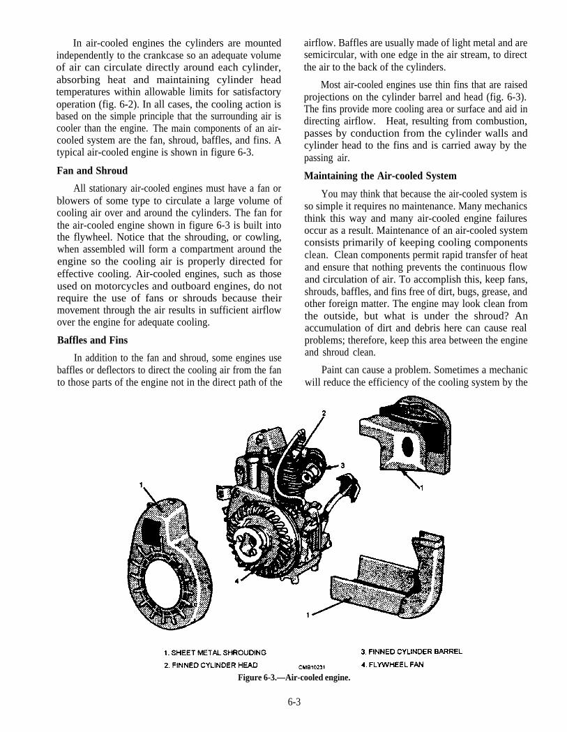
In air-cooled engines the cylinders are mountedindependently to the crankcase so an adequate volumeof air can circulate directly around each cylinder,absorbing heat and maintaining cylinder headtemperatures within allowable limits for satisfactoryoperation (fig. 6-2). In all cases, the cooling action isbased on the simple principle that the surrounding air iscooler than the engine. The main components of an air-cooled system are the fan, shroud, baffles, and fins. Atypical air-cooled engine is shown in figure 6-3.
Fan and Shroud
All stationary air-cooled engines must have a fan orblowers of some type to circulate a large volume ofcooling air over and around the cylinders. The fan forthe air-cooled engine shown in figure 6-3 is built intothe flywheel. Notice that the shrouding, or cowling,when assembled will form a compartment around theengine so the cooling air is properly directed foreffective cooling. Air-cooled engines, such as thoseused on motorcycles and outboard engines, do notrequire the use of fans or shrouds because theirmovement through the air results in sufficient airflowover the engine for adequate cooling.
Baffles and Fins
In addition to the fan and shroud, some engines usebaffles or deflectors to direct the cooling air from the fanto those parts of the engine not in the direct path of the
airflow. Baffles are usually made of light metal and aresemicircular, with one edge in the air stream, to directthe air to the back of the cylinders.
Most air-cooled engines use thin fins that are raisedprojections on the cylinder barrel and head (fig. 6-3).The fins provide more cooling area or surface and aid indirecting airflow. Heat, resulting from combustion,passes by conduction from the cylinder walls andcylinder head to the fins and is carried away by thepassing air.
Maintaining the Air-cooled System
You may think that because the air-cooled system isso simple it requires no maintenance. Many mechanicsthink this way and many air-cooled engine failuresoccur as a result. Maintenance of an air-cooled systemconsists primarily of keeping cooling componentsclean. Clean components permit rapid transfer of heatand ensure that nothing prevents the continuous flowand circulation of air. To accomplish this, keep fans,shrouds, baffles, and fins free of dirt, bugs, grease, andother foreign matter. The engine may look clean fromthe outside, but what is under the shroud? Anaccumulation of dirt and debris here can cause realproblems; therefore, keep this area between the engineand shroud clean.
Paint can cause a problem. Sometimes a mechanicwill reduce the efficiency of the cooling system by the
Figure 6-3.—Air-cooled engine.
6-3
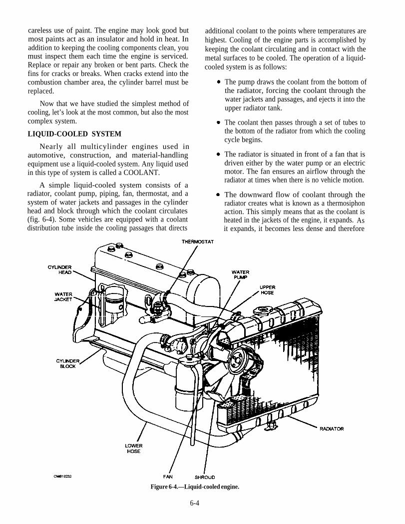
careless use of paint. The engine may look good butmost paints act as an insulator and hold in heat. Inaddition to keeping the cooling components clean, youmust inspect them each time the engine is serviced.Replace or repair any broken or bent parts. Check thefins for cracks or breaks. When cracks extend into thecombustion chamber area, the cylinder barrel must bereplaced.
Now that we have studied the simplest method ofcooling, let’s look at the most common, but also the mostcomplex system.
LIQUID-COOLED SYSTEM
Nearly all multicylinder engines used inautomotive, construction, and material-handlingequipment use a liquid-cooled system. Any liquid usedin this type of system is called a COOLANT.
A simple liquid-cooled system consists of aradiator, coolant pump, piping, fan, thermostat, and asystem of water jackets and passages in the cylinderhead and block through which the coolant circulates(fig. 6-4). Some vehicles are equipped with a coolantdistribution tube inside the cooling passages that directs
additional coolant to the points where temperatures arehighest. Cooling of the engine parts is accomplished bykeeping the coolant circulating and in contact with themetal surfaces to be cooled. The operation of a liquid-cooled system is as follows:
The pump draws the coolant from the bottom ofthe radiator, forcing the coolant through thewater jackets and passages, and ejects it into theupper radiator tank.
The coolant then passes through a set of tubes tothe bottom of the radiator from which the coolingcycle begins.
The radiator is situated in front of a fan that isdriven either by the water pump or an electricmotor. The fan ensures an airflow through theradiator at times when there is no vehicle motion.
The downward flow of coolant through theradiator creates what is known as a thermosiphonaction. This simply means that as the coolant isheated in the jackets of the engine, it expands. Asit expands, it becomes less dense and therefore
Figure 6-4.—Liquid-cooled engine.
6-4
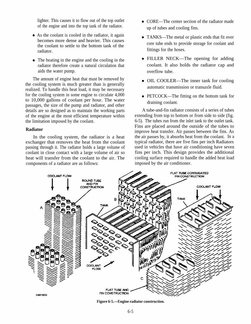
lighter. This causes it to flow out of the top outletof the engine and into the top tank of the radiator.
As the coolant is cooled in the radiator, it againbecomes more dense and heavier. This causesthe coolant to settle to the bottom tank of theradiator.
The heating in the engine and the cooling in theradiator therefore create a natural circulation thataids the water pump.
The amount of engine heat that must be removed bythe cooling system is much greater than is generallyrealized. To handle this heat load, it may be necessaryfor the cooling system in some engine to circulate 4,000to 10,000 gallons of coolant per hour. The waterpassages, the size of the pump and radiator, and otherdetails are so designed as to maintain the working partsof the engine at the most efficient temperature withinthe limitation imposed by the coolant.
Radiator
In the cooling system, the radiator is a heatexchanger that removes the heat from the coolantpassing through it. The radiator holds a large volume ofcoolant in close contact with a large volume of air soheat will transfer from the coolant to the air. Thecomponents of a radiator are as follows:
CORE—The center section of the radiator madeup of tubes and cooling fins.
TANKS—The metal or plastic ends that fit overcore tube ends to provide storage for coolant andfittings for the hoses.
FILLER NECK—The opening for addingcoolant. It also holds the radiator cap andoverflow tube.
OIL COOLER—The inner tank for coolingautomatic transmission or transaxle fluid.
PETCOCK—The fitting on the bottom tank fordraining coolant.
A tube-and-fin radiator consists of a series of tubesextending from top to bottom or from side to side (fig.6-5). The tubes run from the inlet tank to the outlet tank.Fins are placed around the outside of the tubes toimprove heat transfer. Air passes between the fins. Asthe air passes by, it absorbs heat from the coolant. In atypical radiator, there are five fins per inch Radiatorsused in vehicles that have air conditioning have sevenfins per inch. This design provides the additionalcooling surface required to handle the added heat loadimposed by the air conditioner.
Figure 6-5.—Engine radiator construction.
6-5

Radiators are classified according to the directionthat the coolant flows through them. The two types ofradiators are the downflow and crossflow.
The downflow radiator has the coolant tanks onthe top and bottom and the core tubes runvertically. Hot coolant from the engine enters thetop tank. The coolant flows downward throughthe core tubes. After cooling, coolant flows outthe bottom tank and back into the engine.
The crossflow radiator is a design that has thetanks on the sides of the core. The core tubes arearranged for horizontal coolant flow. The tankwith the radiator cap is normally the outer tank.A crossflow radiator can be shorter, allowing fora lower vehicle hood.
The operation of a radiator is as follows:
The upper tank collects incoming coolant and,through the use of an internal baffle, distributes itacross the top of the core.
The core is made up of numerous rows of smallvertical tubes that connect the upper tank and thelower tank. Sandwiched between the rows oftubes are thin sheet metal fins. As the coolantpasses through the tubes to the lower tank, thefins conduct the heat away from it and dissipatethis heat into the atmosphere. The dissipation ofthe heat from the fins is aided by directing aconstant air flow between the tube and over thefins.
The lower tank collects the coolant from the coreand discharges it to the engine through the outletpipe.
The overflow tube provides an opening from theradiator for escape of coolant if the pressure inthe system exceeds the regulated maximum.This will prevent rupture of cooling systemcomponents.
A transmission oil cooler is often placed in theradiator on vehicles with automatic transmissions. It isa small tank enclosed in one of the main radiator tanks.Since the transmission fluid is hotter than enginecoolant, heat is removed from the fluid as it passesthrough the radiator and cooler.
In downflow radiators, the transmission oil cooleris located in the lower tank. In a crossflow radiator, it islocated in the tank having the radiator cap. Both tanksare coolant outlet tanks.
Line fittings from the cooler extend through theradiator tank to the outside. Metal lines from theautomatic transmission connect to these fittings. Thetransmission oil pump forces the fluid through the linesand cooler.
Radiator Hoses
Radiator hoses carry coolant between the enginewater jackets and the radiator. Being flexible, hoses canwithstand the vibration and rocking of the enginewithout breaking.
The upper radiator hose normally connects to thethermostat housing on the intake manifold or cylinderhead. The other end of the hose fits on the radiator. Thelower hose connects the water pump inlet and theradiator.
A molded hose is manufactured into a special shapewith bends to clean the parts especially the cooling fan.It must be purchased to fit the exact year and make of thevehicle.
A flexible hose has an accordion shape and can bebent to different angles. The pleated constructionallows the hose to bend without collapsing and blockingcoolant flow. It is also known as a universal typeradiator hose.
A hose spring is used in the lower radiator hose toprevent its collapse. The lower hose is exposed tosuction from the water pump. The spring assures thatthe inner lining of the hose does NOT tear away, closeup, and stop circulation.
Radiator Pressure Cap
The radiator pressure cap (fig. 6-6) is used on nearlyall of the modern engines. The radiator cap locks ontothe radiator tank filler neck Rubber or metal seals makethe cap-to-neck joint airtight. The functions of thepressure cap are as follows:
1. Seals the top of the radiator tiller neck to preventleakage.
2. Pressurizes system to raise boiling point ofcoolant.
3. Relieves excess pressure to protect againstsystem damage.
4. In a closed system, it allows coolant flow intoand from the coolant reservoir.
The radiator cap pressure valve consists of a spring-loaded disc that contacts the filler neck. The springpushes the valve into the neck to form a seal. Under
6-6
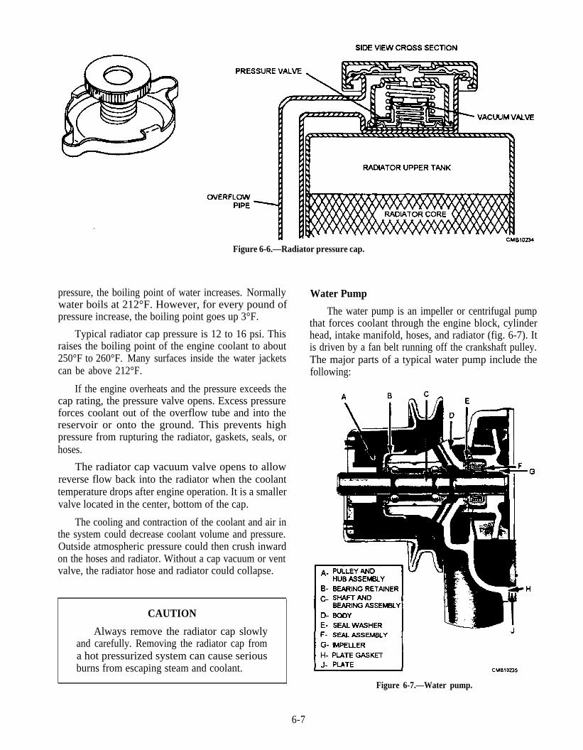
Figure 6-6.—Radiator pressure cap.
pressure, the boiling point of water increases. Normallywater boils at 212°F. However, for every pound ofpressure increase, the boiling point goes up 3°F.
Typical radiator cap pressure is 12 to 16 psi. Thisraises the boiling point of the engine coolant to about250°F to 260°F. Many surfaces inside the water jacketscan be above 212°F.
If the engine overheats and the pressure exceeds thecap rating, the pressure valve opens. Excess pressureforces coolant out of the overflow tube and into thereservoir or onto the ground. This prevents highpressure from rupturing the radiator, gaskets, seals, orhoses.
The radiator cap vacuum valve opens to allowreverse flow back into the radiator when the coolanttemperature drops after engine operation. It is a smallervalve located in the center, bottom of the cap.
The cooling and contraction of the coolant and air inthe system could decrease coolant volume and pressure.Outside atmospheric pressure could then crush inwardon the hoses and radiator. Without a cap vacuum or ventvalve, the radiator hose and radiator could collapse.
CAUTION
Always remove the radiator cap slowlyand carefully. Removing the radiator cap froma hot pressurized system can cause seriousburns from escaping steam and coolant.
Water Pump
The water pump is an impeller or centrifugal pumpthat forces coolant through the engine block, cylinderhead, intake manifold, hoses, and radiator (fig. 6-7). Itis driven by a fan belt running off the crankshaft pulley.The major parts of a typical water pump include thefollowing:
Figure 6-7.—Water pump.
6-7

WATER PUMP IMPELLER—a disc withfanlike blades that spins and produces pressureand flow.
WATER PUMP SHAFT—steel shaft thattransfers turning force from the hub to impeller.
WATER PUMP SEAL—prevents coolantleakage between pump shaft and pump housing.
WATER PUMP BEARING—plain or ballbearing that allows the pump shaft to spin freelyin the housing.
WATER PUMP HUB—provides mountingplace for the belt and fan.
WATER PUMP HOUSING—iron or aluminumcasting that forms the main body of the pump.
The water pump normally mounts on the front ofthe engine. With some transverse (sideways) mountedengines, it may bolt to the side of the engine and extendtowards the front.
A water pump gasket fits between the engine andthe pump housing to prevent coolant leakage. RTVsealer may be used instead of a gasket.
Operation of the water pump is as follows (fig. 6-8):
Figure 6-8.—Water pump operation.
The spinning crankshaft pulley causes the fanbelt to turn the water pump pulley, pump shaft,and impeller.
Coolant trapped between the impeller blades isthrown outward, producing suction in the centralarea of the pump housing.
Since the pump inlet is near the center, coolant ispulled out of the radiator, through the lowerradiator hose.
After being thrown outward and pressurized, thecoolant flows into the engine. It circulatesthrough the block, around the cylinders, upthrough the cylinder heads, and back into theradiator.
Fan and Shroud
The cooling system fan pulls a large volume of airthrough the radiator core that cools the hot watercirculating through the radiator. A fan belt or an electricmotor drives the fan A fan driven by a fan belt, isknown as an engine-powered fan and is bolted to thewater pump hub and pulley. Sometimes a spacer fitsbetween the fan and pulley to move the fan closer to theradiator. Besides removing heat from the coolant in theradiator, the flow of air created by the fan causes somedirect cooling of the engine itself.
Fan blades are spaced at intervals around the fanhub to aid in controlling vibration and noise. They areoften curled at the tip to increase their ability to moveair. Except for differences in location around the hub,most blades have the same pitch and angularity.
Bent fan blades are very common and result innoise, vibration, and excess wear on the water pumpshaft. You should inspect the fan blades, pulleys, pumpshaft end play, and drive belt at every preventivemaintenance inspection.
A variable pitch (flex) fan has thin, flexible bladesthat alter airflow with engine speed (fig. 6-9). These fanblades are made to change pitch as the speed of the fanincreases so that the fan will not create excessive noiseor draw excessive engine power at highway speeds. Atlow speeds, the fan blades remain curved and pull airthrough the radiator. At higher speeds, the blades flexuntil they are almost straight. This reduces fan actionand saves engine power.
The fluid coupling fan clutch is designed to slip athigh speeds, performing the same function as a flexiblefan. The clutch is filled with silicone-based oil. Fan
6-8

Figure 6-9.—Variable pitch fan.
speed is controlled by the torque-carrying capacity ofthe oil. The more oil in the coupling, the greater the fanspeed; the less oil in the coupling, the slower the fanspeed.
The thermostatic fan clutch has a temperaturesensitive, bimetallic spring that controls fan action. Thespring controls oil flow in the fan clutch When cold,the spring causes the clutch to slip, speeding enginewarm-up. After reaching operating temperature, thespring locks the clutch, providing forced air circulation.
An electric engine fan uses an electric motor and athermostatic switch to provide cooling action (fig.6-10). An electric fan is used on front-wheel drivevehicles having transverse mounted engines. The waterpump is normally located away from the radiator.
The fan motor is a small, direct current (dc) motor.It mounts on a bracket secured to the radiator. A metalor plastic fan blade mounts on the end of the motor shaft.
A fan switch or temperature-sensing switchcontrols fan motor operation. When the engine is cold,the switch is open, keeping the fan from spinning, andspeeds engine warm-up. When coolant temperaturereaches approximately 210°F, the switch closes tooperate the fan and provide cooling.
An electric engine fan saves energy and increasescooling system efficiency. It only functions whenneeded. By speeding engine warm-up, it reducesemissions and fuel consumption. In cold weather, theelectric fan may shut off at highway speeds. There may
be enough cool air rushing through the grille of thevehicle to provide adequate cooling. On some models atimed relay may be incorporated that allows the fan torun for a short time after engine shutdown. This, inconjunction with thermosiphon action, helps to preventboilover after engine shutdown.
Figure 6-10.—Electrically motorized fan.
6-9
The radiator shroud ensures that the fan pulls airthrough the radiator. It fastens to the rear of the radiatorand surrounds the area around the fan. When the fan isspinning, the shroud keeps air from circulating betweenthe back of the radiator and the front of the fan. As aresult, a large volume of air flows through the radiatorcore.
Water Jacket
The water passages in the cylinder block andcylinder head form the engine waterjacket (fig. 64). Inthe cylinder block, the water jacket completelysurrounds all cylinders along their full length. Withinthe jacket, narrow passages are provided between thecylinders for coolant circulation around them. Inaddition, water passages are provided around the valveseats and other hot parts of the cylinder block In thecylinder head, the water jacket covers the combustionchambers at the top of the cylinders and containspassages around the valve seats when the valves arelocated in the head.
The passages of the water jacket are designed tocontrol circulation of coolant and provide propercooling throughout the engine. The pump forcescoolant directly from the lower radiator tank connectioninto the forward portion of the cylinder block. This typeof circulation would, obviously, cool the number onecylinder first; causing the rear cylinder to accept coolantprogressively heated by the cylinders ahead. To preventthis condition, the L-head block is equipped with acoolant distribution tube that extends from front to rearof the block, having holes adjacent to (and directed at)the hottest parts of each cylinder. I-head engines areequipped with ferrule type coolant directors that direct ajet of coolant toward the exhaust valve seats.
Thermostats
Automatic control of the temperature of the engineis necessary for efficient engine performance andeconomical operation. If the engine is allowed tooperate at a low temperature, sludge buildup andexcessive fuel consumption will occur. On the otherhand, overheating the engine or operating it abovenormal temperature will result in burnt valves andfaulty lubrication. The latter causes early enginefailure.
The thermostat senses engine temperature andcontrols coolant flow through the radiator. It allowscoolant to circulate freely only withinthe blockuntil thedesired temperature is reached. This action shortens thewarm-up period. The thermostat normally fits under thethermostat housing between the engine and the end ofthe upper radiator hose. The pellet-type thermostat thatis used in modern pressurized cooling systemsincorporates the piston and spring principle (fig. 6-11).The thermostat consists of a valve that is operated by apiston or a steel pin that fits into a small case, containinga copper impregnated wax pellet. A spring holds thepiston and valve in a normally closed position. Whenthe thermostat is heated, the pellet expands and pushesthe valve open. As the pellet and thermostat cools,spring tension overcomes pellet expansion and thevalve closes.
Thermostats are designed to open at specifictemperatures. This is known as thermostat rating.Normal ratings are between 180°F and 195°F forautomotive applications and between 170°F and 203°Ffor heavy-duty applications. Thermostats will begin toopen at their rated temperature and are fully open about20°F higher, For example, a thermostat with a rating of195°F starts to open at that temperature and is fully openat about 215°F.
Most engines have a small coolant bypass passagethat permits some coolant to circulate within thecylinder block and head when the engine is cold and thethermostat is closed. This provides equal warming ofthe cylinders and prevents hot spots. When the enginewarms up, the bypass must close or become restricted.Otherwise, the coolant would continue to circulatewithin the engine and too little would return to theradiator for cooling.
The bypass passage may be an internal passage oran external bypass hose. The bypass hose connects thecylinder block or head to the water pump. There are twointernal bypass systems that can be used on an engine.
One internal bypass system uses a small, spring-loaded valve located in the back of the water pump. Thevalve is forced open by coolant pressure from the pumpwhen the thermostat is closed. As the thermostat opens,the coolant pressure drops within the engine and thebypass valve closes.
6-10
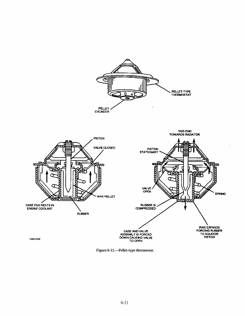
Figure 6-11.—Pellet-type thermostat.
6-11
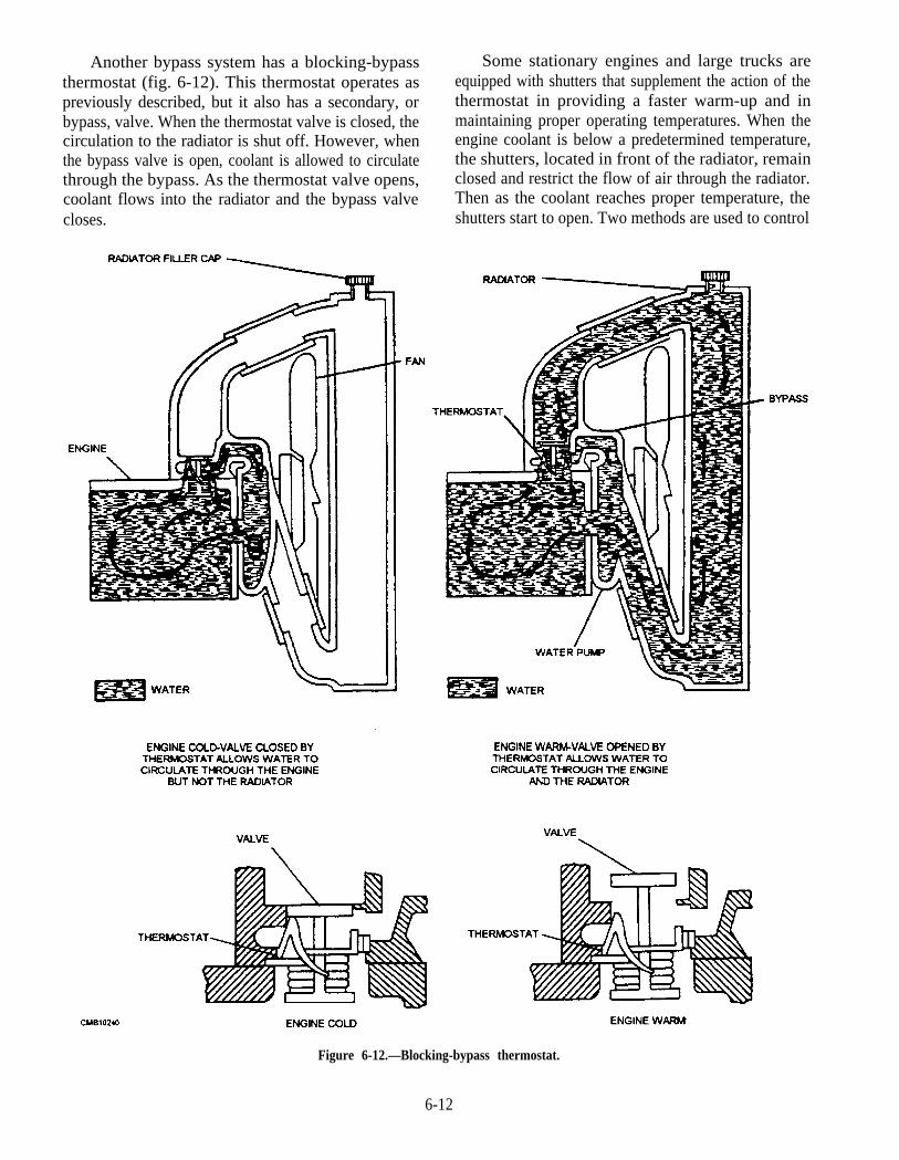
Another bypass system has a blocking-bypassthermostat (fig. 6-12). This thermostat operates aspreviously described, but it also has a secondary, orbypass, valve. When the thermostat valve is closed, thecirculation to the radiator is shut off. However, whenthe bypass valve is open, coolant is allowed to circulatethrough the bypass. As the thermostat valve opens,coolant flows into the radiator and the bypass valvecloses.
Some stationary engines and large trucks areequipped with shutters that supplement the action of thethermostat in providing a faster warm-up and inmaintaining proper operating temperatures. When theengine coolant is below a predetermined temperature,the shutters, located in front of the radiator, remainclosed and restrict the flow of air through the radiator.Then as the coolant reaches proper temperature, theshutters start to open. Two methods are used to control
Figure 6-12.—Blocking-bypass thermostat.
6-12
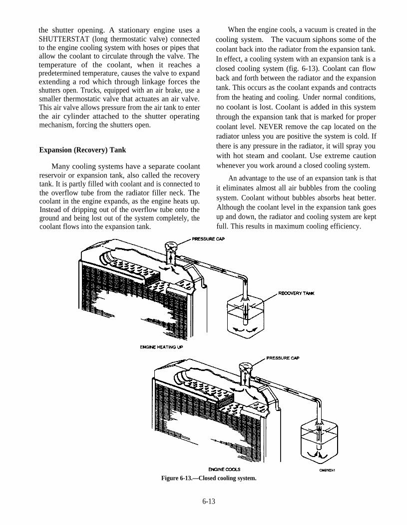
the shutter opening. A stationary engine uses aSHUTTERSTAT (long thermostatic valve) connectedto the engine cooling system with hoses or pipes thatallow the coolant to circulate through the valve. Thetemperature of the coolant, when it reaches apredetermined temperature, causes the valve to expandextending a rod which through linkage forces theshutters open. Trucks, equipped with an air brake, use asmaller thermostatic valve that actuates an air valve.This air valve allows pressure from the air tank to enterthe air cylinder attached to the shutter operatingmechanism, forcing the shutters open.
Expansion (Recovery) Tank
Many cooling systems have a separate coolantreservoir or expansion tank, also called the recoverytank. It is partly filled with coolant and is connected tothe overflow tube from the radiator filler neck. Thecoolant in the engine expands, as the engine heats up.Instead of dripping out of the overflow tube onto theground and being lost out of the system completely, thecoolant flows into the expansion tank.
When the engine cools, a vacuum is created in thecooling system. The vacuum siphons some of thecoolant back into the radiator from the expansion tank.In effect, a cooling system with an expansion tank is aclosed cooling system (fig. 6-13). Coolant can flowback and forth between the radiator and the expansiontank. This occurs as the coolant expands and contractsfrom the heating and cooling. Under normal conditions,no coolant is lost. Coolant is added in this systemthrough the expansion tank that is marked for propercoolant level. NEVER remove the cap located on theradiator unless you are positive the system is cold. Ifthere is any pressure in the radiator, it will spray youwith hot steam and coolant. Use extreme cautionwhenever you work around a closed cooling system.
An advantage to the use of an expansion tank is thatit eliminates almost all air bubbles from the coolingsystem. Coolant without bubbles absorbs heat better.Although the coolant level in the expansion tank goesup and down, the radiator and cooling system are keptfull. This results in maximum cooling efficiency.
Figure 6-13.—Closed cooling system.
6-13
Temperature Gauge and Warning Light
The operator should be warned if the temperature ofthe coolant in the cooling system goes too high. For thisreason, a temperature gauge or warning light is installedin the instrument panel of the vehicle. An abnormalheat rise is a warning of abnormal conditions in theengine. The warning lights alert the operator to stop thevehicle before serious engine damage can occur.Temperature gauges are of two general types—thebalancing-coil (magnetic) type and the bimetal-thermostat (thermal) type.
1. The balancing-coil consists of two coils and anarmature to which a pointer is attached. Anengine-sending unit, that changes resistancewith temperature, is placed in the engine so thatthe end of the unit is in the coolant. When theengine is cold, only a small amount of current isallowed to flow through the right coil; the leftcoil has more magnetism than the right coil. Thepointer, attached to the armature, moves leftindicating that the engine is cold. As the enginewarms up, the sending unit passes more current.More current flows through the right coil,creating a stronger magnetic field. Therefore,the pointer moves ‘to the right to indicate ahigher coolant temperature.
2. The bimetal-thermostat is similar to thebalancing-coil type except for the use of abimetal thermostat in the gauge. Thisthermostat is linked to the pointer. As thesending unit warms up and passes more current,the thermostat heats up and bends. This causesthe pointer to swing to the right to indicate thatthe engine coolant temperature is rising.
A temperature warning light informs the operatorwhen the vehicle is overheating. When the enginecoolant becomes too hot, a sending unit in the engineblock closes, completing the circuit and the dashindicating light comes ON. The indicating light warnsof an overheating condition about 5°F to 10°F belowcoolant boiling point.
In some construction equipment a "prove-out"circuit is incorporated in the system. When the ignitionswitch is turned from OFF to RUN, the light comes on,proving that the system is operating. If the light does notcome on, either the bulb is burned out or the sending unitor connecting wire is defective. The light will go outnormally after the engine starts.
Coolants and Antifreeze
Since water is easily obtained, cheap, and has theability to transfer heat readily, it has served as a basiccoolant for many years. Some properties of water, suchas its boiling point, freezing point, and natural corrosiveaction on metals, limit its usefulness as a coolant. Tocounteract this, use an antifreeze.
Antifreeze, usually ethylene glycol, is mixed withwater to produce the engine coolant. Antifreeze hasseveral functions.
Prevents winter freeze up, which can causeserious damage to the engine and coolingsystem.
Prevents rust and corrosion by providing aprotective film on the metal surfaces.
Lubricates the water pump, which increases theservice life of the pump and seals.
Cools the engine; prevents overheating in hotweather.
For ideal cooling and winter protection, a 50/50mixture of antifreeze and water is recommended. It willprovide protection from ice formation to about –34°F.Higher ratios of antifreeze produce even lower freezingtemperatures; for example, a 60/40 mixture will protectthe cooling system to about –62°F. However, this muchprotection is not normally needed.
WARNING
Ethylene glycol is a toxic material- Avoidprolonged skin contact or accidental ingestion.Wear protective gloves and goggles whilehandling antifreeze and coolants.
SERVICING THE LIQUID-COOLEDSYSTEM
A cooling system is extremely important to theperformance and service life of the engine. Majorengine damage could occur in a matter of minuteswithout proper cooling because combustion heatcollects in metal engine parts. This heat can meltpistons, crack or warp the cylinder head or block, causevalves to burn, or the head gasket to "blow." To preventthese costly problems, keep the cooling system in goodcondition.
6-14
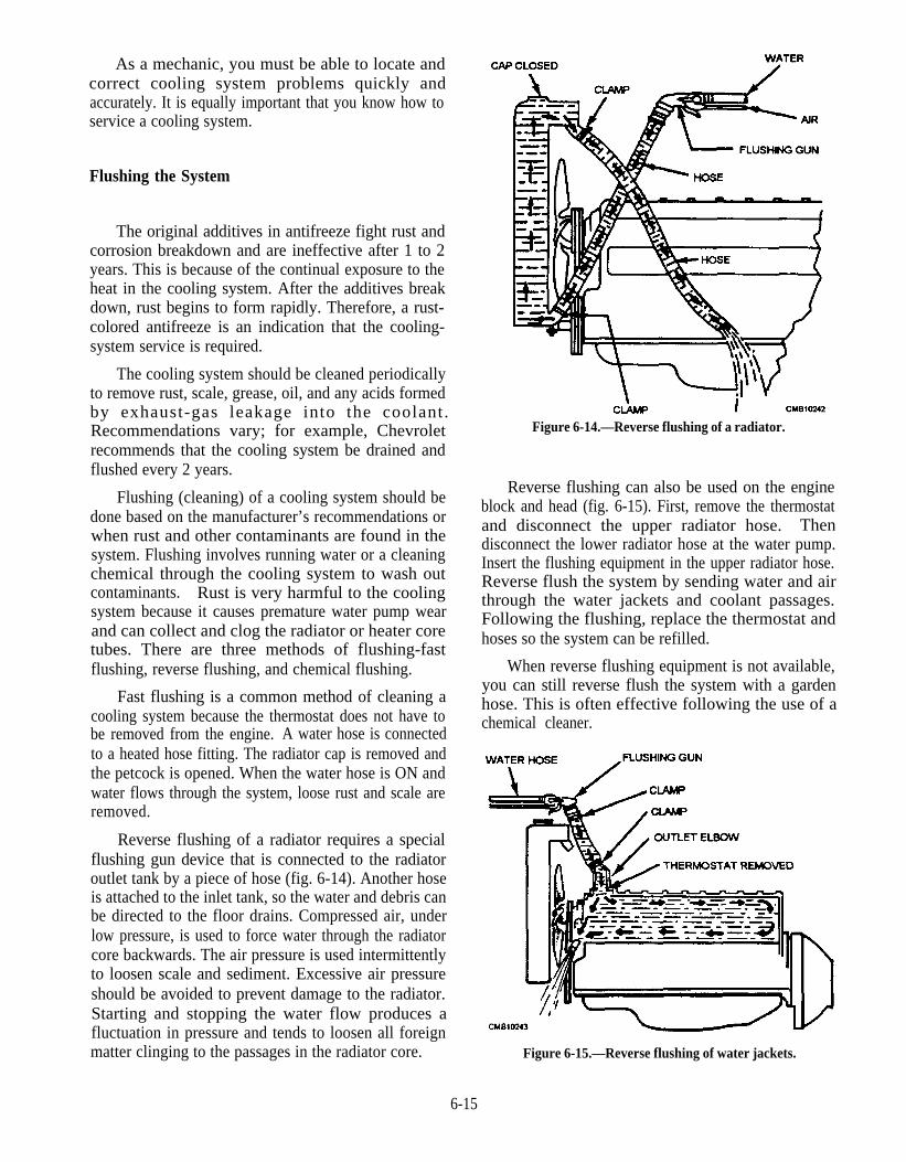
As a mechanic, you must be able to locate andcorrect cooling system problems quickly andaccurately. It is equally important that you know how toservice a cooling system.
Flushing the System
The original additives in antifreeze fight rust andcorrosion breakdown and are ineffective after 1 to 2years. This is because of the continual exposure to theheat in the cooling system. After the additives breakdown, rust begins to form rapidly. Therefore, a rust-colored antifreeze is an indication that the cooling-system service is required.
The cooling system should be cleaned periodicallyto remove rust, scale, grease, oil, and any acids formedby exhaust-gas leakage into the coolant.Recommendations vary; for example, Chevroletrecommends that the cooling system be drained andflushed every 2 years.
Flushing (cleaning) of a cooling system should bedone based on the manufacturer’s recommendations orwhen rust and other contaminants are found in thesystem. Flushing involves running water or a cleaningchemical through the cooling system to wash outcontaminants. Rust is very harmful to the coolingsystem because it causes premature water pump wearand can collect and clog the radiator or heater coretubes. There are three methods of flushing-fastflushing, reverse flushing, and chemical flushing.
Fast flushing is a common method of cleaning acooling system because the thermostat does not have tobe removed from the engine. A water hose is connectedto a heated hose fitting. The radiator cap is removed andthe petcock is opened. When the water hose is ON andwater flows through the system, loose rust and scale areremoved.
Reverse flushing of a radiator requires a specialflushing gun device that is connected to the radiatoroutlet tank by a piece of hose (fig. 6-14). Another hoseis attached to the inlet tank, so the water and debris canbe directed to the floor drains. Compressed air, underlow pressure, is used to force water through the radiatorcore backwards. The air pressure is used intermittentlyto loosen scale and sediment. Excessive air pressureshould be avoided to prevent damage to the radiator.Starting and stopping the water flow produces afluctuation in pressure and tends to loosen all foreignmatter clinging to the passages in the radiator core.
Figure 6-14.—Reverse flushing of a radiator.
Reverse flushing can also be used on the engineblock and head (fig. 6-15). First, remove the thermostatand disconnect the upper radiator hose. Thendisconnect the lower radiator hose at the water pump.Insert the flushing equipment in the upper radiator hose.Reverse flush the system by sending water and airthrough the water jackets and coolant passages.Following the flushing, replace the thermostat andhoses so the system can be refilled.
When reverse flushing equipment is not available,you can still reverse flush the system with a gardenhose. This is often effective following the use of achemical cleaner.
Figure 6-15.—Reverse flushing of water jackets.
6-15
Chemical flushing is needed when a scale buildupin the system is causing engine overheating. Add thechemical cleaner to the coolant. Run the engine at fastidle for about 20 minutes. Wait for the engine to cool.Then drain out the coolant and cleaner solution. Using agarden hose, flush out the loosened rust and scale.Continue to flush until the water runs clear.
CAUTION
Always follow manufacturer’sinstructions when using a cooling systemcleaning agent. Wear protective gloves andgoggles when handling cleaning agents.Chemicals may cause eye and skin burns.
Antifreeze Service
Antifreeze should be checked and changed atregular intervals. After prolonged use, antifreeze willbreak down and become very corrosive. It can lose itsrust preventative properties and the cooling system canfill rapidly with rust.
A visual inspection of the antifreeze will helpdetermine its condition. Rub your lingers inside theradiator filler neck. Check for rust, oil (internal engineleak), scale, or transmission fluid (leaking oil cooler).
6-16
Also check to find out how long the antifreeze hasbeen in service. If contaminated or too old, replace theantifreeze. If badly rusted, you may need to flush thesystem. Antifreeze should be changed whencontaminated or when 2 years old. Check the servicemanual for exact change schedules.
Antifreeze strength is a measurement of theconcentration of antifreeze compared to water. Itdetermines the freeze-up protection of the solution.There are two devices used to check antifreezestrength—the antifreeze hydrometer and therefractometer.
The antifreeze hydrometer is used to measure thefreezing point of the cooling system. A squeezeand release bulb draws coolant into the tester,and a needle floats to show the freeze protectionpoint.
With the refractometer, you draw coolant into thetester. Then place a few drops of coolant on themeasuring window (surface). Aim the tester at alight and view through the tester sight. The scale
in the refractometer indicates the freezeprotection point.
Minimum antifreeze strength should be severaldegrees lower than the lowest possible temperature forthe climate of the area. For example, if the lowestnormal temperature for the area is 10oF, the antifreezeshould test to -20°F. A 50/50 mixture of antifreeze andwater is commonly used to provide protection for mostweather conditions.
NOTE
Vehicles, using an aluminum coolingsystem and engine parts, can be corroded bysome types of antifreeze. Use only antifreezedesigned for aluminum components. Checkthe vehicles service manual or antifreeze labelfor details.
COOLING SYSTEM TESTS
It is often necessary to check the cooling system forcooling system problems. Cooling system problemscan be grouped into three general categories:
1. COOLANT LEAKS—crack or rupture,allowing pressure cap action to push coolant outof the system.
2. OVERHEATING—engine operatingtemperature too high, warning light on,temperature gauge shows hot, or coolant andsteam is blowing out the overflow.
3. OVERCOOLING—engine fails to reach fulloperating temperature, engine performancepoor or sluggish.
To diagnose and repair cooling system problems,perform several tests. These tests include thefollowing—cooling system pressure test, combustionleak test, thermostat test, engine fan test, and fan belttest.
Cooling System Pressure Test
A cooling system pressure test is used to locateleaks quickly. Low air pressure is forced into thesystem, causing coolant to pour or drip from any leak inthe system.
A pressure tester is a hand-operated air pump usedto pressurize the system for leak detection. Install thepressure tester on the radiator filler neck. Then pump
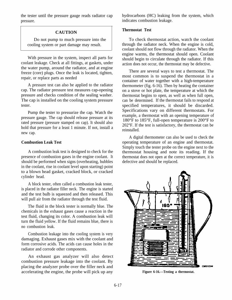
the tester until the pressure gauge reads radiator cappressure.
CAUTION
Do not pump to much pressure into thecooling system or part damage may result.
With pressure in the system, inspect all parts forcoolant leakage. Check at all fittings, at gaskets, underthe water pump, around the radiator, and at enginefreeze (core) plugs. Once the leak is located, tighten,repair, or replace parts as needed
A pressure test can also be applied to the radiatorcap. The radiator pressure test measures cap-openingpressure and checks condition of the sealing washer.The cap is installed on the cooling system pressuretester.
Pump the tester to pressurize the cap. Watch thepressure gauge. The cap should release pressure at itsrated pressure (pressure stamped on cap). It should alsohold that pressure for a least 1 minute. If not, install anew cap.
Combustion Leak Test
A combustion leak test is designed to check for thepresence of combustion gases in the engine coolant. Itshould be performed when signs (overheating, bubblesin the coolant, rise in coolant level upon starting) pointto a blown head gasket, cracked block, or crackedcylinder head.
A block tester, often called a combustion leak tester,is placed in the radiator filler neck. The engine is startedand the test bulb is squeezed and then released. Thiswill pull air from the radiator through the test fluid.
The fluid in the block tester is normally blue. Thechemicals in the exhaust gases cause a reaction in thetest fluid, changing its color. A combustion leak willturn the fluid yellow. If the fluid remains blue, there isno combustion leak.
Combustion leakage into the cooling system is verydamaging. Exhaust gases mix with the coolant andform corrosive acids. The acids can cause holes in theradiator and corrode other components.
An exhaust gas analyzer will also detectcombustion pressure leakage into the coolant. Byplacing the analyzer probe over the filler neck andaccelerating the engine, the probe will pick up any
hydrocarbons (HC) leaking from the system, whichindicates combustion leakage.
Thermostat Test
To check thermostat action, watch the coolantthrough the radiator neck. When the engine is cold,coolant should not flow through the radiator. When theengine warms, the thermostat should open. Coolantshould begin to circulate through the radiator. If thisaction does not occur, the thermostat may be defective.
There are several ways to test a thermostat. Themost common is to suspend the thermostat in acontainer of water together with a high-temperaturethermometer (fig. 6-16). Then by heating the containeron a stove or hot plate, the temperature at which thethermostat begins to open, as well as when full open,can be determined. If the thermostat fails to respond atspecified temperatures, it should be discarded.Specifications vary on different thermostats. Forexample, a thermostat with an opening temperature of180°F to 185°F, full-open temperature is 200°F to202°F. If the test is satisfactory, the thermostat can bereinstalled.
A digital thermometer can also be used to check theoperating temperature of an engine and thermostat.Simply touch the tester probe on the engine next to thethermostat housing and note its reading. If thethermostat does not open at the correct temperature, it isdefective and should be replaced.
Figure 6-16.—Testing a thermostat.
6-17
The use of a temperature stick is another way to testa thermostat quickly. The temperature stick is a pencil-like device that contains a wax material containingcertain chemicals that melt at a given temperature.Using two sticks (one for opening temperature and theother for full-open temperature), rub the sticks on thethermostat housing. As the coolant warms to operatingtemperature, the wax-like marks will melt. If the marksdo not melt, the thermostat is defective and needs to bereplaced.
radiator and pressure cap. Proper service of thecomponents ensures an efficient cooling system andextends the life of the vehicle.
Water Pump
Engine Fan Test
A bad water pump may leak coolant, fail to circulatecoolant, or it may produce a grinding sound. Rust in thecooling system or lack of antifreeze is the most commoncauses for pump failure. These conditions canaccelerate seal, shaft, and bearing wear. Anover-tightened fan belt will also cause water pumpfailure.
A faulty engine fan can cause overheating,overcooling, vibration, and water pump wear, ordamage. Testing the fan ensures that it is operatingproperly.
To test a thermostatic fan clutch, start the engine.The fan should slip when cold; as the engine warms up,the clutch should engage. Air should begin to flowthrough the radiator and over the engine. You will beable to hear and feel the air when the fan clutch locks up.
If the fan clutch is locked all the time (cold or hot), itis defective and must be replaced. Excessive play or oilleakage also indicates fan clutch failure.
When testing an electric cooling fan, observewhether the fan turns ON when the engine is warm.Make sure the fan motor is spinning at normal speed andforcing enough air through the radiator.
If the fan does not function, check the fuse,electrical connections, and supply voltage to the motor.If the fan motor fails to operate with voltage applied,replace it.
6-18
If the engine is warm and no voltage is supplied tothe fan motor, check the action of the fan switch. Useeither a voltmeter or test light. The switch should havealmost zero resistance (pass current and voltage) whenthe engine is warm. Resistance should be infinite (stopcurrent and voltage) when the engine is cold.
If these tests do not locate the trouble with theelectric cooling fan, refer to the manufacturer’s servicemanual for instructions. There may be a defective relay,connection, or other problem.
SERVICE AND REPAIR OF COOLINGSYSTEM COMPONENTS
The individual components of the cooling systemwhich require servicing and repair include the waterpump, thermostat, hoses, fan and fan belt, and the
To check for a worn water pump seal, pressure testthe system and watch for coolant leakage. Coolant willleak out of the small drain hole at the bottom of thepump or at the end of the pump shaft.
Worn water pump bearings are checked bywiggling the fan or pump pulley up and down. If thepump shaft is loose in its housing, the pump bearings arebadly worn. A stethoscope can also be used to listen forworn, noisy water pump bearings.
Water pump action can be checked with a warmengine. Squeeze the top radiator hose while someonestarts the engine. You should feel a pressure surge (hoseswelling) if the pump is working. If not, pump shaft orimpeller problems are indicated. You can also watch forcoolant circulation in the radiator with the engine atoperating temperature.
Whether a defective pump is replaced or rebuiltdepends on parts supply and cost. A water pump rebuildinvolves disassembly, cleaning, part inspection, wornpart replacement, and reassembly. Few mechanicsrebuild water pumps because rebuilding takes too muchtime and is not cost effective.
The removal and installation of the water pumpvaries with different vehicles. Therefore, the applicableshop manual must be consulted for the step-by-stepprocedures.
When you replace a pump, install a new gasket.Make sure the mating surfaces are clean and smooth.The application of a gasket sealer to both sides of thegasket is recommended. Then after refilling the coolingsystem, the pump should be checked for leaks, noise,and proper operation.
Thermostat
There are no repairs or adjustments to be made onthe thermostat. The unit must be replaced when it fails
to operate properly. A stuck thermostat can either causeengine overheating or overcooling.
If a thermostat is stuck closed, coolant will notcirculate through the radiator. As a result, overheatingcould make the coolant boil.
When a thermostat is stuck open, too much coolantmay circulate through the radiator and the engine maynot reach proper operating temperature. The enginemay run poorly for extended periods in cold weather.Engine efficiency (power, fuel mileage, anddriveability) will be reduced.
The procedure for thermostat replacement is asfollows:
To remove the thermostat, drain the coolant andremove the upper radiator hose from the engine.
Remove the retaining cap screws holding thethermostat housing to the engine. Tap thehousing free with a rubber hammer. Lift off thehousing and thermostat.
Scrape all of the old gasket material off thethermostat housing and sealing surface of theengine.
Make sure that the housing is not warped. Placeit on a flat surface and check the gaps betweenthe housing and the surface. If warped, file thesurface flat. This action will prevent coolantleakage.
Make sure the temperature rating is correct.Then place the thermostat into the engine.Normally, the pointed end on the thermostatshould face the radiator hose. The pelletchamber should face the inside of the engine.
Position the new gasket with approved sealer.Start the cap screws by hand. Then torque themto the manufacturer's specifications in analternating pattern DO NOT overtighten thehousing bolts or warpage and or breakage mayresult. Most housings are made of soft aluminumor "pot metal."
Hoses
Old radiator hoses and heater hoses are frequentcauses of cooling system problems. Hoses should bechecked periodically for leakage and general condition.The leakage may often be corrected by tightening orreplacing hose clamps. After a few years of use, hoses
deteriorate. They may become soft and mushy, or hardand brittle. Deteriorated hoses should be replaced topreclude future troubles. Cooling system pressure canrupture the hoses and result in coolant loss.
Inspect the radiator and heater hoses for cracks,bulges, cuts, or any other sign of deterioration. Squeezethe hoses to check whether they are hardened orsoftened and faulty. Flex or bend heater hoses andwatch for signs of surface cracks. If any problem isdetected, the affected hose should be replaced.However, where spiral spring stiffeners are used tocontrol the tendency to collapse, such test will not workand the hose must be removed for inspection.
Fan and Belt
One of the easiest and quickest checks to thecooling system is the fan and fan belt. Check the fan forbent blades, cracks, and other problems. A bent ordistorted fan on one with a loose blade should bereplaced. Where the fan is just loose on its mounting,tightening is in order.
Fan belts, or drive belts, should be checked for wearand tension. Most wear occurs on the underside of thebelt. To check a V-belt, twist the belt with your fingers.Check for small cracks, grease, glazing, and tears orsplits. Small cracks will enlarge as the belt is flexed.Grease rots the rubber and makes the side slick so thatthe belt slips easily. A high-pitched squeal results fromslippage. Large tears or splits in a belt allow it to betossed from the pulley. On vehicles with a set of twobelts, replace both if one is worn and requiresreplacement.
Use a belt tension gauge to check and adjust the fanbelt tension. When you do not have a gauge or if spacedoes not allow use of a gauge, you can make a quickcheck of belt tension. Press down on the free span of thebelt, a point midway between the alternator or generatorpulley and the fan pulley. Measure the amount ofdeflection. When free span is less than 12 inchesbetween pulleys, belt deflection should be 1/8 to 1/4inch. When free span is longer than 12 inches, beltdeflection should be 1/4 to 1/2 inch.
A slipping belt can cause overheating and a run-down battery. These troubles result because a slippingbelt cannot drive the water pump and alternator fastenough for normal operation. Sometimes a belt will slipand make noise even after it is adjusted to the propertension. Several types of belt dressing are availablewhich can be applied to both sides of the belt to preventthis problem. Belt dressing helps to eliminate noise andincrease belt friction.
6-19
The fan belt should be checked every time a vehiclecomes in for preventive maintenance (PM) to make sureit is in good condition. A fan belt that has becomefrayed, or has separated plies, should be replaced.
Replacement of a defective belt is usually made byloosening the alternator or generator mounting bolts.With the mounting bolts loose, push the alternator orgenerator closer to the engine. This action providesenough slack in the belt so it can be removed and a newone installed. After installing a new belt, adjust it to theproper tension and tighten the mounting bolts.
Radiator and Pressure Cap
When overheating problems occur and the systemis not leaking, check the radiator and pressure cap. Theyare common sources of overheating. The pressure capcould have bad seals, allowing pressure loss. Theradiator may be clogged and not permitting adequate airflow or coolant flow.
Bent fins should he straightened and the radiatorcore checked for any obstructions tending to restrict theairflow. Radiator air passages can be cleaned byblowing them out with an air hose in the directionopposite to the ordinary flow of air. Water can also beused to soften obstructions before applying the air blast.In any event, the cleaning gets rid of dirt, bugs, leaves,straw, and other debris which otherwise would clog theradiator and reduce its cooling efficiency. Sometimesscreens are used in front of the radiator core to reducethis type of clogging.
The radiator can be checked for internal cloggingby removing the hose connections and draining thecoolant. Use a garden hose to introduce a stream ofwater into the top of the radiator. If the flow is sluggish,the radiator is partially clogged. Another way to checkfor this condition is to feel the radiator with your hand.The radiator should be warm at the bottom and hot at thetop, with the temperature uniformly increasing frombottom to top. Any clogged sections will feel cool.
CAUTION
Be sure the engine is not running whenmaking this test to avoid injury from the fan.
When the use of cleaning compounds and reverseflushing fails to relieve a clogged core, the radiator mustbe removed for mechanical cleaning. This requires theremoval of upper and lower radiator tanks and roddingout the accumulated rust and scale from the waterpassages of the core.
The radiator pressure cap should also be checkedfor condition and proper operation. If it is dirty, the capcan be cleaned with soap and water, then rinsed. Theseating surface of the vacuum and pressure valvesshould be smooth and undamaged The valves shouldoperate freely when pressed against their springpressure and should seal properly when closed.
During the vehicles preventive maintenance (PM)inspection, the radiator should be checked for leaks,particularly where the tanks are soldered to the core,since vibration and pulsation from pressure can causefatigue of soldered joints or seams. Neglect of smallleaks may result in complete radiator failure, excessiveleakage, rust clogging, and overheating. Thus it isextremely important to keep the radiator mountingproperly adjusted and tight at all times and to detect andcorrect even the smallest leaks.
A leak usually reveals its presence by scale marks orwatermarks below the leak on the outside of the core.Permanent antifreeze does not leak through spaceswhere water cannot pass. The antifreeze leak is morenoticeable, since it does not evaporate as quickly aswater.
Stop-leak compounds can be effective to stop smallleaks at least temporarily. Stop-leak compounds hardenupon contact with the air, thus sealing off any smallopenings. The main problem is that they give themechanic a sense of false security. For example, stopleak may prevent seepage at a hose connection throughthe inner lining, but finally the hose will rot and burst,losing coolant and overheating the engine.
Stop-leak compounds can lead to radiator cloggingif water tubes already contain deposits that act as astrainer. If coolant level gets too low, some stop-leakingredients may harden in the upper radiator and blockit.
NOTE
Before using stop leak, check your servicemanual. The compound must be compatiblewith the antifreeze and the inhibitors and mustbe installed correctly and in the right quantity.
When large leaks or considerable damage ispresent, removal of the radiator for extensive repair orreplacement is usually required.
Q1. What type of cooling system is the simplest?
Q2. In a liquid-cooled system, what component actsas a heat exchanger?
6-20

Q3.
Q4.
Q5.
Q6.
Q7.
Q8.
What are the two types of radiators?
Where is the vacuum valve located in theradiator cap?
What type of fan clutch uses a bimetal spring tocontrol fan action?
What component of a liquid-cooled systemsenses engine temperature and controls coolantflow through the radiator?
When replacing antifreeze, what is the idealmixture you recommend?
What are the three methods of flushing a liquid-cooled system?
Q9. What two devices am used to check antifreeze
strength?
Q10. What device is used to perform a cooling systempressure test?
ENGINE LUBRICATINGSYSTEMS
LEARNING OBJECTIVE: Identify types oflubricating (oil) systems. Point out theiroperational characteristics and maintenancerequirements.
All internal combustion engines are equipped withan internal lubricating system (fig. 6-17). Without
Figure 6-17.—Typical engine lubrication system.
6-21

lubrication, an engine quickly overheats and itsworking parts seize due to excessive friction. Allmoving parts must be adequately lubricated to assuremaximum wear and long engine life.
PURPOSES OF LUBRICATION
The functions of an engine lubrication system are asfollows:
Reduces friction and wear between moving parts(fig. 6-18).
Helps transfer heat and cool engine parts.
Cleans the inside of the engine by removingcontaminants (metal, dirt, plastic, rubber, andother particles) (fig. 6-19).
Absorbs shocks between moving parts to quietengine operation and increase engine life.
The properties of engine oil and the design ofmodern engines allow the lubrication system toaccomplish these functions.
ENGINE OIL
Engine oil, also called motor oil, is used to producea lubricating film on the moving parts in an engine. Themilitary specification for this type of oil prescribes thatthe oil shall be a petroleum or synthetic petroleumproduct or a combination thereof. This oil is intendedfor lubrication of internal-combustion engines otherthan aircraft engines or for general-purpose lubrication.
Oil Viscosity and Measurements
Oil viscosity, also called oil weight, is the thicknessor fluidity (flow ability) of the oil. A high viscosity oil isvery thick and resists flow. A low viscosity oil is verythin and flows easily.
Figure 6-18.—How oil lubricates.
6-22
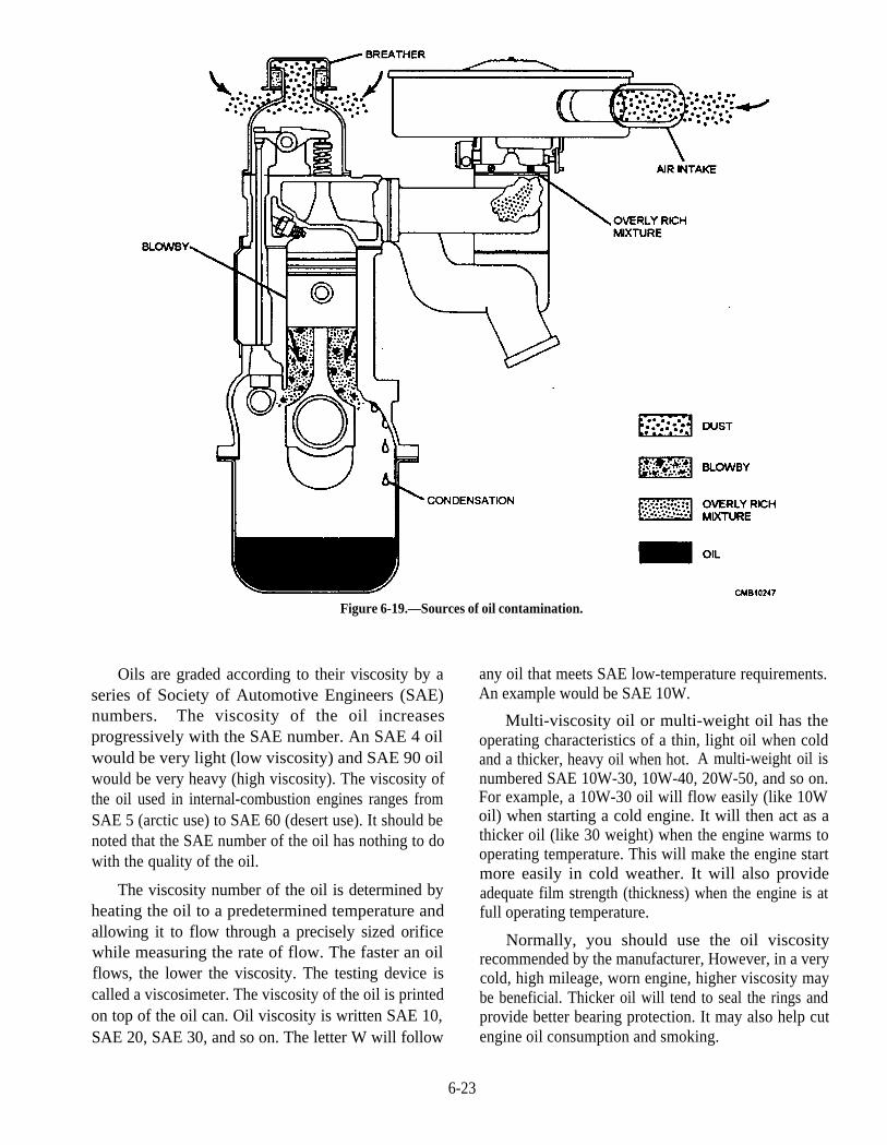
Oils are graded according to their viscosity by aseries of Society of Automotive Engineers (SAE)numbers. The viscosity of the oil increasesprogressively with the SAE number. An SAE 4 oilwould be very light (low viscosity) and SAE 90 oilwould be very heavy (high viscosity). The viscosity ofthe oil used in internal-combustion engines ranges fromSAE 5 (arctic use) to SAE 60 (desert use). It should benoted that the SAE number of the oil has nothing to dowith the quality of the oil.
The viscosity number of the oil is determined byheating the oil to a predetermined temperature andallowing it to flow through a precisely sized orificewhile measuring the rate of flow. The faster an oilflows, the lower the viscosity. The testing device iscalled a viscosimeter. The viscosity of the oil is printedon top of the oil can. Oil viscosity is written SAE 10,SAE 20, SAE 30, and so on. The letter W will follow
Figure 6-19.—Sources of oil contamination.
any oil that meets SAE low-temperature requirements.An example would be SAE 10W.
Multi-viscosity oil or multi-weight oil has theoperating characteristics of a thin, light oil when coldand a thicker, heavy oil when hot. A multi-weight oil isnumbered SAE 10W-30, 10W-40, 20W-50, and so on.For example, a 10W-30 oil will flow easily (like 10Woil) when starting a cold engine. It will then act as athicker oil (like 30 weight) when the engine warms tooperating temperature. This will make the engine startmore easily in cold weather. It will also provideadequate film strength (thickness) when the engine is atfull operating temperature.
Normally, you should use the oil viscosityrecommended by the manufacturer, However, in a verycold, high mileage, worn engine, higher viscosity maybe beneficial. Thicker oil will tend to seal the rings andprovide better bearing protection. It may also help cutengine oil consumption and smoking.
6-23
Oil Service Rating
The oil service rating is a set of letters printed on theoil can to denote how well the oil will perform underoperating conditions. The American PetroleumInstitute (API) sets this performance standard.
The API system for rating oil classifies oilaccording to its performance characteristics. Thehigher rated oils contain additives that providemaximum protection against rust, wear, oil oxidation,and thickening at high temperatures. The oil serviceratings are as follows:
1. SA—adequate for utility engines subjected tolight loads, moderate speeds, and cleanconditions. Contains no additives.
2. SB—adequate for automotive use underfavorable conditions (light loads, low speeds,and moderate temperatures) with relativelyshort oil change intervals. Generally offersonly minimal protection to the engine againstbearing scuffing, corrosion, and oiloxidation.
3. SC—meets oil warranty requirements for1964 through 1967 automotive gasolineengines.
4. SD—meets oil warranty requirements for1968 through 1970 automotive gasolineengines. Offers additional protection over SCoils that are necessary with the introduction ofemission controls.
5. SE—meets oil warranty requirements for 1972through 1979 automotive gasoline engines.Stricter emission requirements created theneed for this detergent oil.
6. SF—meets oil warranty requirements for 1980through 1988 automotive gasoline engines.The SF oil is designed to meet the demands ofsmall, high-revving engines. A SF oil can beused in all automotive vehicles requiringdetergent oil.
7. SG—meets oil warranty requirements for1989 through present automotive gasolineengines. Contains more additives than SF oils.Can be used as CC or diesel type oils. It is adetergent oil.
8. CA—meets all requirements for naturallyaspirated diesel engines operated on low sulfurfuel.
9.
10.
11.
The
CB—meets all requirements for naturallyaspirated diesel engines operated on highsulfur fuel.
CC—meets all requirements for lightlysupercharged diesel engines.
CD—meets all requirements for moderatelysupercharged diesel engines.
operator's manual provides the service ratingrecommended for a specific vehicle. You can use abetter service rating than recommended, but NEVER alower service rating. A high service rating (SG, forexample) can withstand higher temperatures and loadswhile still maintaining a lubricating film. It will havemore oil additives to prevent oil oxidation, enginedeposits, breakdown, foaming, and other problems.
LUBRICATING (OIL) SYSTEMCOMPONENTS
It must be remembered that the lubricating systemis actually an integral part of the engine and theoperation of one depends upon the operation of theother. Thus the lubricating system, in actual practice,cannot be considered as a separate and independentsystem; it is part of the engine. The lubricating systembasically consists of the following:
Oil Pan—reservoir or storage area for engine oil.
Oil Level Gauge—checks the amount of oil inthe oil pan.
Oil Pump—forces oil throughout the system.
Oil Pickup and Strainers—carries oil to thepump and removes large particles.
Oil Filters—strains out impurities in the oil.
Oil Galleries—oil passages through the engine.
Oil Pressure Indicator—warns the operator oflow oil pressure.
Oil Pressure Gauge—registers actual oilpressure in the engine.
Oil Temperature Regulator—controls engine oiltemperature on diesel engines.
Oil Pan
The oil pan, normally made of thin sheet metal oraluminum, bolts to the bottom of the engine block. It
6-24

Figure 6-20.—Oil level gauge.
holds a supply of oil for the lubrication system. The oilpan is fitted with a screw-in drain plug for oil changes.Baffles may be used to keep the oil from splashingaround in the pan.
The sump is the lowest area in the oil pan where oilcollects. As oil drains from the engine, it fills the sump.Then the oil pump can pull oil out of the pan forrecirculation.
Oil Level Gauge
The oil level gauge, also known as a dipstick, isusually of the bayonet type (fig. 6-20). It consists of along rod or blade that extends into the oil pan. It ismarked to show the level of oil within the oil pan.Readings are taken by pulling the rod out from itsnormal place in the crankcase, wiping it clean, replacingit, and again removing and noting the height of the oil onthe lower or marked end. This should be done with theengine stopped unless the manufacturer recommendsotherwise. It is important that the oil level not dropbelow the LOW mark or rise above the FULL mark.
Oil Pump
The oil pump is the heart of the lubricating system;it forces oil out of the oil pan, through the oil filter,galleries, and to the engine bearings. Normally, a gearon the engine camshaft drives the oil pump; however, acogged belt or a direct connection with the end of thecamshaft or crankshaft drives the pump in some cases.
There are two basic types of oil pumps—rotary andgear.
The ROTARY pump (fig. 6-21) has an inner rotorwith lobes that match similar shaped depressions in the
Figure 6-21.—Rotor-type oil pump.
6-25
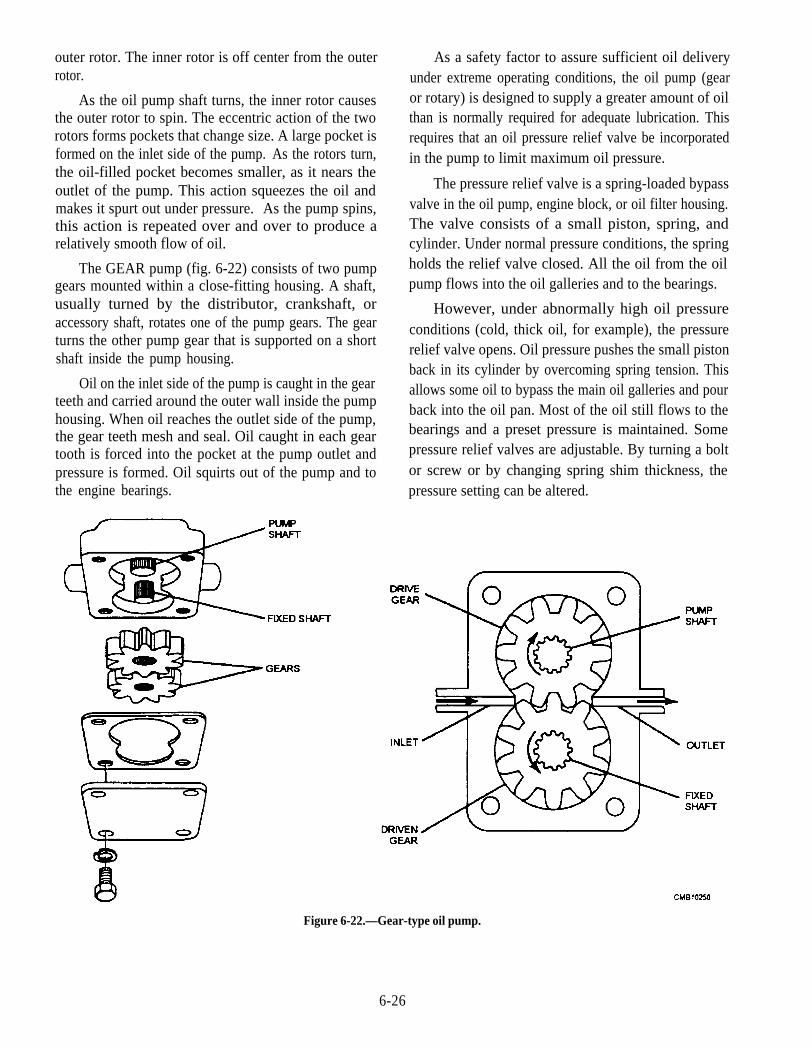
outer rotor. The inner rotor is off center from the outerrotor.
As the oil pump shaft turns, the inner rotor causesthe outer rotor to spin. The eccentric action of the tworotors forms pockets that change size. A large pocket isformed on the inlet side of the pump. As the rotors turn,the oil-filled pocket becomes smaller, as it nears theoutlet of the pump. This action squeezes the oil andmakes it spurt out under pressure. As the pump spins,this action is repeated over and over to produce arelatively smooth flow of oil.
The GEAR pump (fig. 6-22) consists of two pumpgears mounted within a close-fitting housing. A shaft,usually turned by the distributor, crankshaft, oraccessory shaft, rotates one of the pump gears. The gearturns the other pump gear that is supported on a shortshaft inside the pump housing.
As a safety factor to assure sufficient oil deliveryunder extreme operating conditions, the oil pump (gearor rotary) is designed to supply a greater amount of oilthan is normally required for adequate lubrication. Thisrequires that an oil pressure relief valve be incorporatedin the pump to limit maximum oil pressure.
The pressure relief valve is a spring-loaded bypassvalve in the oil pump, engine block, or oil filter housing.The valve consists of a small piston, spring, andcylinder. Under normal pressure conditions, the springholds the relief valve closed. All the oil from the oilpump flows into the oil galleries and to the bearings.
However, under abnormally high oil pressureconditions (cold, thick oil, for example), the pressurerelief valve opens. Oil pressure pushes the small pistonback in its cylinder by overcoming spring tension. Thisallows some oil to bypass the main oil galleries and pourback into the oil pan. Most of the oil still flows to thebearings and a preset pressure is maintained. Somepressure relief valves are adjustable. By turning a boltor screw or by changing spring shim thickness, the
Oil on the inlet side of the pump is caught in the gearteeth and carried around the outer wall inside the pumphousing. When oil reaches the outlet side of the pump,the gear teeth mesh and seal. Oil caught in each geartooth is forced into the pocket at the pump outlet andpressure is formed. Oil squirts out of the pump and tothe engine bearings. pressure setting can be altered.
Figure 6-22.—Gear-type oil pump.
6-26
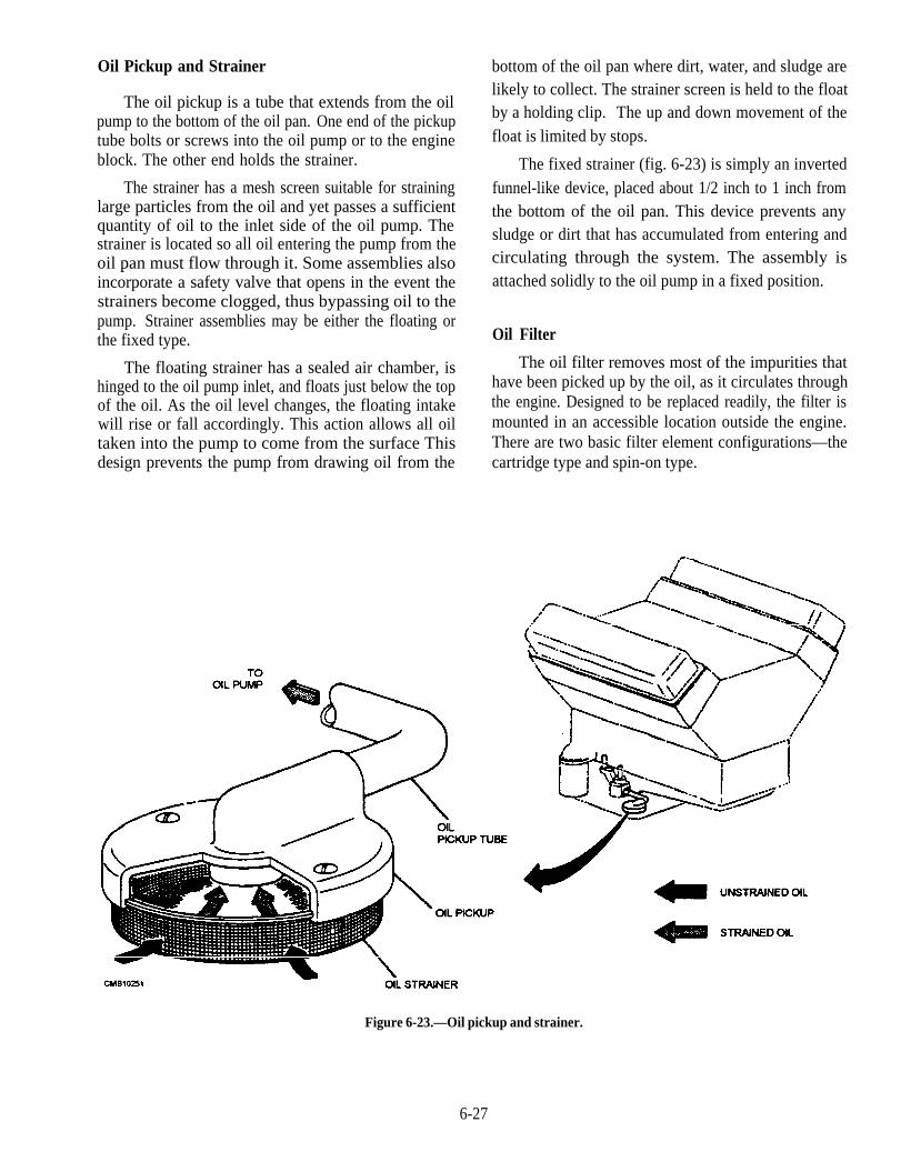
Oil Pickup and Strainer
The oil pickup is a tube that extends from the oilpump to the bottom of the oil pan. One end of the pickuptube bolts or screws into the oil pump or to the engineblock. The other end holds the strainer.
The strainer has a mesh screen suitable for straininglarge particles from the oil and yet passes a sufficientquantity of oil to the inlet side of the oil pump. Thestrainer is located so all oil entering the pump from theoil pan must flow through it. Some assemblies alsoincorporate a safety valve that opens in the event thestrainers become clogged, thus bypassing oil to thepump. Strainer assemblies may be either the floating orthe fixed type.
The floating strainer has a sealed air chamber, ishinged to the oil pump inlet, and floats just below the topof the oil. As the oil level changes, the floating intakewill rise or fall accordingly. This action allows all oiltaken into the pump to come from the surface Thisdesign prevents the pump from drawing oil from the
bottom of the oil pan where dirt, water, and sludge arelikely to collect. The strainer screen is held to the floatby a holding clip. The up and down movement of thefloat is limited by stops.
The fixed strainer (fig. 6-23) is simply an invertedfunnel-like device, placed about 1/2 inch to 1 inch fromthe bottom of the oil pan. This device prevents anysludge or dirt that has accumulated from entering andcirculating through the system. The assembly isattached solidly to the oil pump in a fixed position.
Oil Filter
The oil filter removes most of the impurities thathave been picked up by the oil, as it circulates throughthe engine. Designed to be replaced readily, the filter ismounted in an accessible location outside the engine.There are two basic filter element configurations—thecartridge type and spin-on type.
Figure 6-23.—Oil pickup and strainer.
6-27
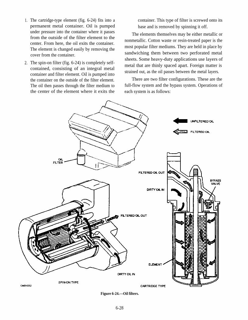
1. The cartridge-type element (fig. 6-24) fits into apermanent metal container. Oil is pumpedunder pressure into the container where it passesfrom the outside of the filter element to thecenter. From here, the oil exits the container.The element is changed easily by removing thecover from the container.
2. The spin-on filter (fig. 6-24) is completely self-contained, consisting of an integral metalcontainer and filter element. Oil is pumped intothe container on the outside of the filter element.The oil then passes through the filter medium tothe center of the element where it exits the
container. This type of filter is screwed onto itsbase and is removed by spinning it off.
The elements themselves may be either metallic ornonmetallic. Cotton waste or resin-treated paper is themost popular filter mediums. They are held in place bysandwiching them between two perforated metalsheets. Some heavy-duty applications use layers ofmetal that are thinly spaced apart. Foreign matter isstrained out, as the oil passes between the metal layers.
There are two filter configurations. These are thefull-flow system and the bypass system. Operations ofeach system is as follows:
Figure 6-24.—Oil filters.
6-28
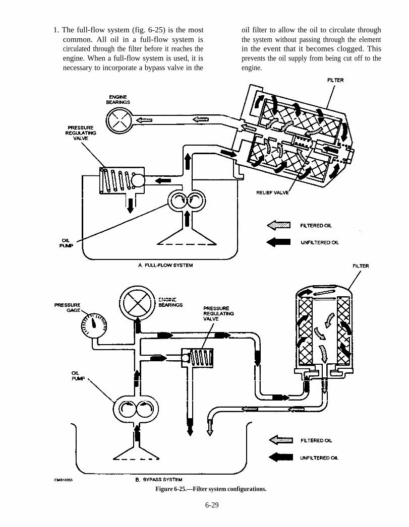
1. The full-flow system (fig. 6-25) is the most oil filter to allow the oil to circulate throughcommon. All oil in a full-flow system is the system without passing through the elementcirculated through the filter before it reaches the in the event that it becomes clogged. Thisengine. When a full-flow system is used, it is prevents the oil supply from being cut off to thenecessary to incorporate a bypass valve in the engine.
Figure 6-25.—Filter system configurations.
6-29
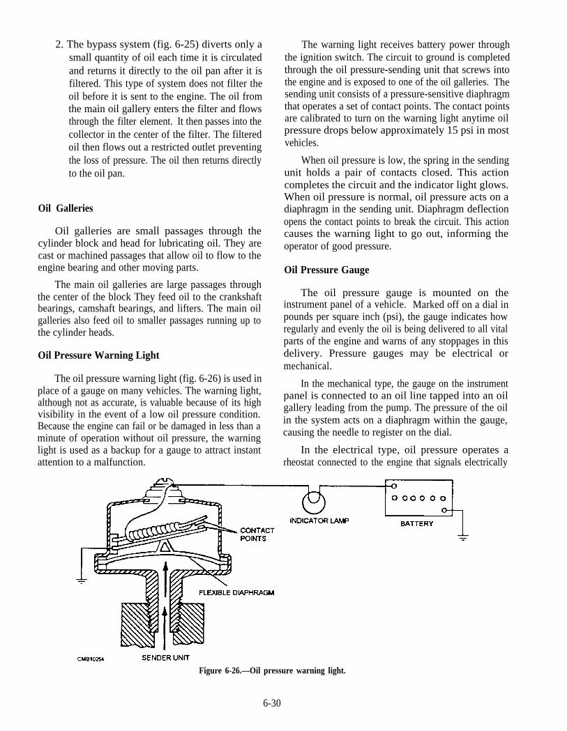
2. The bypass system (fig. 6-25) diverts only asmall quantity of oil each time it is circulatedand returns it directly to the oil pan after it isfiltered. This type of system does not filter theoil before it is sent to the engine. The oil fromthe main oil gallery enters the filter and flowsthrough the filter element. It then passes into thecollector in the center of the filter. The filteredoil then flows out a restricted outlet preventingthe loss of pressure. The oil then returns directlyto the oil pan.
Oil Galleries
Oil galleries are small passages through thecylinder block and head for lubricating oil. They arecast or machined passages that allow oil to flow to theengine bearing and other moving parts.
The main oil galleries are large passages throughthe center of the block They feed oil to the crankshaftbearings, camshaft bearings, and lifters. The main oilgalleries also feed oil to smaller passages running up tothe cylinder heads.
Oil Pressure Warning Light
The oil pressure warning light (fig. 6-26) is used inplace of a gauge on many vehicles. The warning light,although not as accurate, is valuable because of its highvisibility in the event of a low oil pressure condition.Because the engine can fail or be damaged in less than aminute of operation without oil pressure, the warninglight is used as a backup for a gauge to attract instantattention to a malfunction.
The warning light receives battery power throughthe ignition switch. The circuit to ground is completedthrough the oil pressure-sending unit that screws intothe engine and is exposed to one of the oil galleries. Thesending unit consists of a pressure-sensitive diaphragmthat operates a set of contact points. The contact pointsare calibrated to turn on the warning light anytime oilpressure drops below approximately 15 psi in mostvehicles.
When oil pressure is low, the spring in the sendingunit holds a pair of contacts closed. This actioncompletes the circuit and the indicator light glows.When oil pressure is normal, oil pressure acts on adiaphragm in the sending unit. Diaphragm deflectionopens the contact points to break the circuit. This actioncauses the warning light to go out, informing theoperator of good pressure.
Oil Pressure Gauge
The oil pressure gauge is mounted on theinstrument panel of a vehicle. Marked off on a dial inpounds per square inch (psi), the gauge indicates howregularly and evenly the oil is being delivered to all vitalparts of the engine and warns of any stoppages in thisdelivery. Pressure gauges may be electrical ormechanical.
In the mechanical type, the gauge on the instrumentpanel is connected to an oil line tapped into an oilgallery leading from the pump. The pressure of the oilin the system acts on a diaphragm within the gauge,causing the needle to register on the dial.
In the electrical type, oil pressure operates arheostat connected to the engine that signals electrically
Figure 6-26.—Oil pressure warning light.
6-30

Figure 6-27.—Oil temperature regulator.
to the pressure gauge indicating oil pressure within thesystem.
Oil Temperature Regulator
The oil temperature regulator (fig. 6-27) must beused in diesel engine lubricating systems, prevents oil
temperature from rising too high in hot weather, andassists in raising the temperature during cold starts inwinter weather. It provides a more positive means ofcontrolling oil temperature than does cooling byradiation of heat from the oil pan wells.
The regulator uses engine coolant in the coolingsystem to regulate the temperature of the oil and is madeup of a core and housing. The core, through which theoil circulates, is of cellular or bellows construction andis built to expose as much oil as possible to the coolantthat circulates through the housing. The regulator isattached to the engine so that the oil will flow throughthe regulator after passing through the pump. As the oilpasses through the regulator, it is either cooled orheated, depending on the temperature of the coolant andthen is circulated through the engine.
Some military vehicles use an oil cooler (fig. 6-28)that consists of a radiator through which air is circulatedby movement of the vehicle or by a cooling fan. Oilfrom the engine is circulated through this radiator andback to the sump or supply tank. The radiator acts tocool the oil only in this system. It will not heat oil in acold engine.
Figure 6-28.—Oil cooler.
6-31

Figure 6-29.—Splash-type lubrication system.
TYPES OF LUBRICATING (OIL)SYSTEMS
Now that you are familiar with the lubricatingsystem components, you are ready to study the differentsystems that circulate oil through the engine. Thesystems used to circulate oil are known as splash,combination splash force feed, force feed, and fullforce-feed.
Splash
The splash system is no longer used in automotiveengines. It is widely used in small four-cycle enginesfor lawn mowers, outboard marine operation, and so on.
In the splash lubricating system (fig. 6-29), oil issplashed up from the oil pan or oil trays in the lower partof the crankcase. The oil is thrown upward as dropletsor fine mist and provides adequate lubrication to valvemechanisms, piston pins, cylinder walls, and pistonrings.
In the engine, dippers on the connecting-rodbearing caps enter the oil pan with each crankshaftrevolution to produce the oil splash. A passage is drilledin each connecting rod from the dipper to the bearing toensure lubrication.
This system is too uncertain for automotiveapplications. One reason is that the level of oil in thecrankcase will vary greatly the amount of lubricationreceived by the engine. A high level results in excesslubrication and oil consumption and a slightly low levelresults in inadequate lubrication and failure of theengine.
Combination Splash and Force Feed
In a combination splash and force feed (fig. 6-30),oil is delivered to some parts by means of splashing and
Figure 6-30.—Combination splash and force-feed lubrication system.
6-32
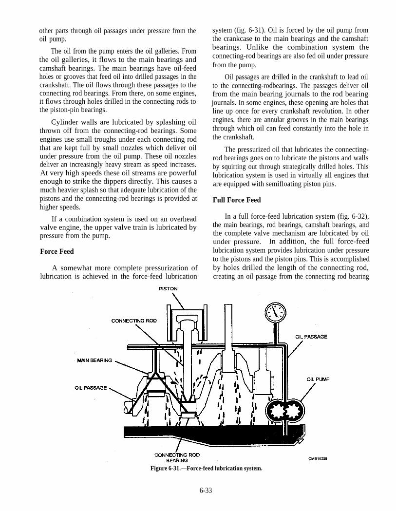
other parts through oil passages under pressure from theoil pump.
The oil from the pump enters the oil galleries. Fromthe oil galleries, it flows to the main bearings andcamshaft bearings. The main bearings have oil-feedholes or grooves that feed oil into drilled passages in thecrankshaft. The oil flows through these passages to theconnecting rod bearings. From there, on some engines,it flows through holes drilled in the connecting rods tothe piston-pin bearings.
Cylinder walls are lubricated by splashing oilthrown off from the connecting-rod bearings. Someengines use small troughs under each connecting rodthat are kept full by small nozzles which deliver oilunder pressure from the oil pump. These oil nozzlesdeliver an increasingly heavy stream as speed increases.At very high speeds these oil streams are powerfulenough to strike the dippers directly. This causes amuch heavier splash so that adequate lubrication of thepistons and the connecting-rod bearings is provided athigher speeds.
If a combination system is used on an overheadvalve engine, the upper valve train is lubricated bypressure from the pump.
Force Feed
A somewhat more complete pressurization oflubrication is achieved in the force-feed lubrication
system (fig. 6-31). Oil is forced by the oil pump fromthe crankcase to the main bearings and the camshaftbearings. Unlike the combination system theconnecting-rod bearings are also fed oil under pressurefrom the pump.
Oil passages are drilled in the crankshaft to lead oilto the connecting-rodbearings. The passages deliver oilfrom the main bearing journals to the rod bearingjournals. In some engines, these opening are holes thatline up once for every crankshaft revolution. In otherengines, there are annular grooves in the main bearingsthrough which oil can feed constantly into the hole inthe crankshaft.
The pressurized oil that lubricates the connecting-rod bearings goes on to lubricate the pistons and wallsby squirting out through strategically drilled holes. Thislubrication system is used in virtually all engines thatare equipped with semifloating piston pins.
Full Force Feed
In a full force-feed lubrication system (fig. 6-32),the main bearings, rod bearings, camshaft bearings, andthe complete valve mechanism are lubricated by oilunder pressure. In addition, the full force-feedlubrication system provides lubrication under pressureto the pistons and the piston pins. This is accomplishedby holes drilled the length of the connecting rod,creating an oil passage from the connecting rod bearing
Figure 6-31.—Force-feed lubrication system.
6-33

Figure 6-32.—Full force-feed lubrication system.
to the piston pin bearing. This passage not only feedsthe piston pin bearings but also provides lubrication forthe pistons and cylinder walls. This system is used invirtually all engines that are equipped with full-floatingpiston pins.
LUBRICATING SYSTEM PROBLEMDIAGNOSIS
To troubleshoot an engine lubricating system, beginby gathering information on the problem. Ask theoperator questions. Analyze the symptoms using yourunderstanding of system operation. You should arriveat a logical deduction about the cause of the problem.
The four problems most often occur in thelubrication system are as follows:
1. High oil consumption (oil must be addedfrequently)
2. Low oil pressure (gauge reads low, indicatorlight glows, or abnormal engine noises)
3. High oil pressure (gauge reads high, oil filterswelled)
4. Defective indicator or gauge circuit (inaccurateoperation or readings)
When diagnosing these troubles, make a visualinspection of the engine for obvious problems. Checkfor oil leakage, disconnected sending unit wire, low oil
level, damaged oil pan, or other troubles that relate tothe symptoms.
High Oil Consumption
If the operator must add oil frequently to the engine,this is a symptom of high oil consumption. External oilleakage out of the engine or internal leakage of oil intothe combustion chambers causes high oil consumption.A description of each of these problems is as follows:
External oil leakage—detected as darkened oilwet areas on or around the engine. Oil may alsobe found in small puddles under the vehicle.Leaking gaskets or seals are usually the source ofexternal engine oil leakage.
Internal oil leakage—shows up as blue smokeexiting the exhaust system of the vehicle. Forexample, if the engine piston rings and cylindersare badly worn, oil can enter the combustionchambers and will be burned during combustion
NOTE
Do not confuse black smoke (excess fuelin the cylinder) and white smoke (waterleakage into the engine cylinder) with bluesmoke caused by engine oil.
6-34
Low Oil Pressure
Low oil pressure is indicated when the oil indicatorlight glows, oil gauge reads low, or when the enginelifters or bearings rattle. The most common causes oflow oil pressure are as follows:
1. Low oil level (oil not high enough in pan tocover oil pickup)
2. Worn connecting rod or main bearings (pumpcannot provide enough oil volume)
3. Thin or diluted oil (low viscosity or fuel in theoil)
4. Weak or broken pressure relief valve spring(valve opening too easily)
5. Cracked or loose pump pickup tube (air beingpulled into the oil pump)
6. Worn oil pump (excess clearance between rotoror gears and housing)
7. Clogged oil pickup screen (reduce amount of oilentering pump)
A low oil level is a common cause of low oilpressure. Always check the oil level first whentroubleshooting a low oil pressure problem.
High Oil Pressure
High oil pressure is seldom a problem. When itoccurs, the oil pressure gauge will read high. The mostfrequent causes of high oil pressure are as follows:
1. Pressure relief valve struckopen (not opening atspecified pressure)
2. High relief valve spring tension (strong springor spring has been improperly shimmed)
3. High oil viscosity (excessively thick oil or useof oil additive that increases viscosity)
4. Restricted oil gallery (defective block casting ordebris in oil passage)
Indicator or Gauge Problems
A bad oil pressure indicator or gauge may scare theoperator into believing there are major problems. Theindicator light may stay on or flicker, pointing to a lowoil pressure problem. The gauge may read low or high,also indicating a lubrication system problem.
Inspect the indicator or gauge circuit for problems.The wire going to the sending unit may have fallen off.
The sending unit wire may also be shorted to ground(light stays on or gauge always reads high).
To check the action of the indicator or gauge,remove the wire from the sending unit. Touch it on ametal part of the engine. This should make the indicatorlight glow or the oil pressure gauge read maximum. If itdoes, the sending unit may be defective. If it does not,then the circuit, indicator, or gauge may be faulty.
NOTE
Always check the service manual beforetesting an indicator or gauge circuit. Somemanufacturers recommend a special gaugetester. This is especially important with somecomputer-controlled systems.
LUBRICATING SYSTEM MAINTENANCE
There are certain lubricating system service jobsthat are more or less done automatically when an engineis repaired. For example, the oil pan is removed andcleaned during such engine overhaul jobs as replacingbearing or rings. When the crankshaft is removed, it isusual procedure to clean out the oil passages in thecrankshaft. Also, the oil passages in the cylinder blockshould be cleaned out as part of the overhaul.
As a Construction Mechanic, you will be requiredto maintain the lubrication system. This maintenancenormally consists of changing the oil and filter(s).Occasionally you will be required to perform suchmaintenance tasks as replacing lines and fittings,servicing or replacing the oil pump and relief valve, andflushing the system. The following discussion providesinformation that will aid you in carrying out theseduties.
Oil and Filter Change
It is extremely important that the oil and filter(s) ofthe engine are serviced regularly. Lack of oil and filtermaintenance will greatly shorten engine service life.
Manufacturers give a maximum number of miles orhours a vehicle can be operated between oil changes.Newer automotive vehicles can be operated 5,000 milesbetween changes. Older automotive vehicles shouldhave their oil changed about every 3,000 miles. Mostconstruction equipment average between 200 and 250hours of operation between oil changes. However,depending on the climate and working conditions the
6-35
miles and hours between oil changes can be greatlyreduced. Refer to the service manual for exact intervals.
To change the engine oil, warm the engine to fulloperating temperature. This will help suspend debris inthe oil and make the oil drain more thoroughly.Unscrew the drain plug and allow the oil to flow into acatchment pan Be careful of hot oil; it can cause painfulburns.
Usually the filter elements are replaced at the sametime the oil is changed. The most common filters are thespin-on filter or replaceable element type oil filter.
Spin-on, throwaway oil filter—replaced as acomplete unit. Unscrew the filter from the baseby hand or a filter wrench and throw the filteraway. When replacing, wipe the base clean witha cloth and place a small amount of oil or greaseon the gasket to ensure a good seal. Screw on anew filter, tightening at least a half a turn after thegasket contacts the base. Do not use a filterwrench because the filter canister could distortand leak.
Replaceable element oil filter—removed fromthe filter housing and replaced. Place a panunderneath the filter to catch oil from the filter.Remove the fastening bolt and lift off the coveror filter housing. Remove the gasket from thecover or housing and throw it away. Take out theold element and throw it away. Clean the insideof the filter housing and cover it. Install a newelement and insert a new cover or housing gasket(ensure the gasket is completely seated in therecess). Replace the cover or housing and fastenit to the center bolt securely.
After the oil has been completely drained and thedrain plug replaced, fill the crankcase to the full mark onthe dipstick with the proper grade and weight of oil.Start and idle the engine. Check the oil pressureimmediately. Inspect the filter or filter housing forleaks. Stop the engine and check the crankcase oil leveland add to the full mark.
Oil Pump Service
Service on oil pumps is limited since they arerelatively trouble-free. An oil pump will often still beoperating trouble-free when the vehicle is ready forsalvage.
A bad oil pump will cause low or no oil pressure andpossibly severe engine damage. When inner parts wear,
the pump may leak and have a reduced output. Thepump shaft can also strip in the pump or distributor,preventing pump operation
To replace the oil pump, it is first necessary todetermine its location. Some pumps are located insidethe engine oil pan Others are on the front of the engineunder a front cover or on the side of the engine. Sinceremoval procedures vary, refer to the manufacturer’sservice manual for instructions.
Most mechanics install a new or factory rebuiltpump when needed. It is usually too costly tocompletely rebuild an oil pump in the shop. Beforeinstallation, prime (fill) the pump with engine oil. Thiswill assure proper initial operation upon enginestarting.
Install the pump in reverse order of removal. Anewgasket should be used and the retaining bolts torqued asspecified by the service manual.
Pressure Relief Valve Service
A faulty pressure relief valve can produce oilpressure problems. The valve may be located in the oilpump, filter housing, or engine block.
If symptoms point to the pressure relief valve, itshould be disassembled and serviced. Cleaning andadjusting is all that is usually required. Remove the cupor cap, holding the pressure relief valve. Then, slide thespring and piston out of their bore.
Measure the free length of the spring (length ofextended spring) and compare it to the specifications. Ifthe spring is too short or long, install a new spring.Some manufacturers recommend checking springtension.
Use a micrometer and a small hole gauge to checkthe valve and valve bore wear. Also, check the sides ofthe valve for scratches or scoring. Replace the parts ifany problems are found.
Assemble the pressure relief valve. Make sure thatthe valve is facing correctly in its bore. Slide the springinto place. Install any shims and the cover plug or cap.Refer to the service manual for details.
The pressure relief valve may be adjusted in one oftwo ways. One way is by an adjusting screw (having ajam or locknut) which adds or relives pressure on thespring. The other way is by adjusting shims that areadded or removed to adjust opening pressure of therelief valve.
6-36

Q11. What device is used to determine the viscosity ofoil ?
Q12. How is oil that meets SAE low temperaturerequirements designated?
Q13. Who sets the oil service rating?
Q14. What oil service rating is required for today’sautomotive gasoline engines?
Q15. What are the two oil filter configurations?
Q16. Name the four types of lubricating systems?
Q17. What type of lubricating system is used on smallfour-cycle engines?
Q18. What lubricating system is used on enginesequipped with full-floating piston pins?
Q19. When servicing the pressure relief valve, youcan use what tools to check the valve and valvebore?
6-37

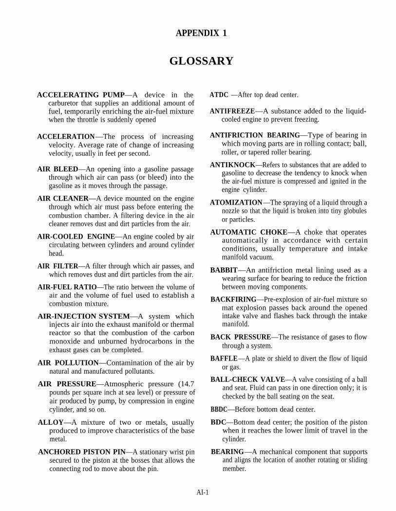
APPENDIX 1
GLOSSARY
ACCELERATING PUMP—A device in thecarburetor that supplies an additional amount offuel, temporarily enriching the air-fuel mixturewhen the throttle is suddenly opened
ACCELERATION—The process of increasingvelocity. Average rate of change of increasingvelocity, usually in feet per second.
AIR BLEED—An opening into a gasoline passagethrough which air can pass (or bleed) into thegasoline as it moves through the passage.
AIR CLEANER—A device mounted on the enginethrough which air must pass before entering thecombustion chamber. A filtering device in the aircleaner removes dust and dirt particles from the air.
AIR-COOLED ENGINE—An engine cooled by aircirculating between cylinders and around cylinderhead.
AIR FILTER—A filter through which air passes, andwhich removes dust and dirt particles from the air.
AIR-FUEL RATIO—The ratio between the volume ofair and the volume of fuel used to establish acombustion mixture.
AIR-INJECTION SYSTEM—A system whichinjects air into the exhaust manifold or thermalreactor so that the combustion of the carbonmonoxide and unburned hydrocarbons in theexhaust gases can be completed.
AIR POLLUTION—Contamination of the air bynatural and manufactured pollutants.
AIR PRESSURE—Atmospheric pressure (14.7pounds per square inch at sea level) or pressure ofair produced by pump, by compression in enginecylinder, and so on.
ALLOY—A mixture of two or metals, usuallyproduced to improve characteristics of the basemetal.
ANCHORED PISTON PIN—A stationary wrist pinsecured to the piston at the bosses that allows theconnecting rod to move about the pin.
ATDC —After top dead center.
ANTIFREEZE—A substance added to the liquid-cooled engine to prevent freezing.
ANTIFRICTION BEARING—Type of bearing inwhich moving parts are in rolling contact; ball,roller, or tapered roller bearing.
ANTIKNOCK—Refers to substances that are added togasoline to decrease the tendency to knock whenthe air-fuel mixture is compressed and ignited in theengine cylinder.
ATOMIZATION—The spraying of a liquid through anozzle so that the liquid is broken into tiny globulesor particles.
AUTOMATIC CHOKE—A choke that operatesautomatically in accordance with certainconditions, usually temperature and intakemanifold vacuum.
BABBIT—An antifriction metal lining used as awearing surface for bearing to reduce the frictionbetween moving components.
BACKFIRING—Pre-explosion of air-fuel mixture somat explosion passes back around the openedintake valve and flashes back through the intakemanifold.
BACK PRESSURE—The resistance of gases to flowthrough a system.
BAFFLE—A plate or shield to divert the flow of liquidor gas.
BALL-CHECK VALVE—A valve consisting of a balland seat. Fluid can pass in one direction only; it ischecked by the ball seating on the seat.
BBDC—Before bottom dead center.
BDC—Bottom dead center; the position of the pistonwhen it reaches the lower limit of travel in thecylinder.
BEARING—A mechanical component that supportsand aligns the location of another rotating or slidingmember.
AI-1

BIMETAL—Referring to the thermostatic bimetalelement made up of two different metals withdifferent heat expansion rates; temperature changeproduces a bending or distorting movement.
BLOCK—See CYLINDER BLOCK
BLOW-BY—Leakage of the compressed air-fuelmixture or burned gases from combustion, passingpiston and rings, and into the crankcase.
BLOWER—A mechanical device for compressing anddelivering air to the engine at higher thanatmospheric pressure.
BOILING POINT—The temperature at which a liquidboils.
BOOST PRESSURE—The pressure in the intakemanifold while the turbocharger is operating.
BORE—The diameter of a cylinder. Also used todescribe the process of enlarging or accuratelyrefinishing an engine cylinder.
BRAKE HORSEPOWER—The power actuallydelivered by the engine that is available for drivingthe vehicle.
AI-2
BTDC—Before top dead center.
BUSHING—A replaceable lining for a hole in which ashaft, rod, or similar part moves.
BUTTERFLY—The choke or throttle valve.
BYPASS—A separate passage that permits a liquid totake a path other than that normally used.
CALIBRATION —(l) Balancing: The setting of thedelivery of an injection system or the setting of therack pointer on a single unit pump in relation topredetermined positions of a quantity controlmember. (2) Adjustment: Fixing fuel delivery andspeed adjustments to specified enginerequirements.
CAM-GROUND—A process by which the piston isground slightly egg-shaped and, when heatbecomes round.
CAMSHAFT—The shaft in an engine that has a seriesof cam lobes for operating the valve mechanism.
CAMSHAFT PUMP—An injection pump containinga camshaft to operate the pumping element orelements.
CARBON—A substance deposited on engine parts bythe combustion of fuel. Carbon forms on pistons,rings, valves, and so on, inhibiting their action.
CARBON DIOXIDE—A gas resulting from burningfuel.
CARBON MONOXIDE—A colorless, odorless,tasteless, deadly gas found in engine exhaust,formed by incomplete burning of hydrocarbons.
CARBURETION —The action that takes place in thecarburetor: converting liquid fuel to vapor andmixing it with air to form a combustible mixture.
CARBURETOR —The device in a gasoline fuelsystem that mixes air and fuel and delivers thecombustible mixture to the intake manifold.
CATALYTIC CONVERTER—A device used on theexhaust system of gasoline engines to reduceharmful emissions.
CETANE—Ignition quality of diesel fuel. A high-cetane fuel ignites more easily (at lowertemperature) than a low-cetane fuel.
CFM—Cubic feet per minute.
CHOKE—A device in the carburetor that chokes off,or reduces, the flow of air into the intake manifold;producing a partial vacuum in the intake manifoldand a consequent richer air-fuel mixture.
CID—Cubic inch displacement.
CLOSED CRANKCASE VENTILATINGSYSTEM—A system in which the crankcasevapors are discharged into the engine intake systemand pass through the engine cylinders rather thanbeing discharged into the air.
CLOSED NOZZLE—A nozzle incorporating either apoppet valve or a needle valve, loaded in order toopen at some predetermined pressure.
COMBUSTION —The rapid burning of the air-fuelmixture in the cylinder.
COMBUSTION CHAMBER—The space at the topof the cylinder and in the head where combustion ofthe air-fuel mixture takes place.
COMPRESSION—The act of pressing into a smallerspace or reducing in size or volume by pressure.
COMPRESSION RATIO—The ratio between thevolume in the cylinder with the piston at bottomdead center and with the piston at top dead center.

COMPRESSION RINGS—The upper rings on apiston; the rings designed to hold the compressionin the cylinder and prevent blow-by.
COMPRESSION STROKE—The piston stroke frombottom dead center during which both valves areclosed and the gases in the cylinder are compressed.
CONCENTRIC—Having a common center, as circlesor spheres, one within the other.
CONNECTING ROD—Linkage between thecrankshaft and piston, usually attached to the pistonby a piston pin and to the crank journal on thecrankshaft by a split bearing and bearing cap.
CONTROL PINON—A collar engaging the plungerand having a segment of gear teeth, integral orattached, which mesh with the control rack.
CONTROL RACK—A toothed rod inside mechanicalinjection pumps that rotates the pump plunger tocontrol the quantity of fuel injected.
COOLANT—The liquid that circulates in an enginecooling system that reduces heat generated by theengine.
COOLING FAN—The fan in the engine coolingsystem that provides a forced circulation of airthrough the radiator or around the engine cylindersso that cooling is affected.
COOLING PINS—The thin metal projections on theair-cooled engine cylinder and head that greatlyincreases the heat-radiating surfaces and helpsprovide cooling of engine cylinder.
COOLING SYSTEM—A system that reduces heatgenerated by the engine and thereby preventsengine overheating, including liquid-cooledengines, engine water jackets, radiator, and waterpump.
CRANKCASE—The lower part of the engine thatserves as a housing for the crankshaft.
CRANKSHAFT—The main rotating member or shaftof the engine that converts rotary motion intoreciprocating motion.
CYCLE—A series of events with a start and finishduring which a definite train of events takes place.
CYLINDER—A hollow tube that contains the actionsof combustion gases and the piston in an internalcombustion engine.
CYLINDER BLOCK—The part of the engine towhich and in which other engine parts andaccessories are attached or assembled.
CYLINDER HEAD—The part of the engine thatencloses the cylinder bores; contains water jackets(on liquid-cooled engines) and valves (on I-headengines).
CYLINDER SLEEVE—A pipe-shaped removableinsert used as the cylinder wall on some engines.
DASHPOT—A device that controls the rate at whichthe throttle valve closes.
DEAD CENTER—Either of the two positions whenthe crank and connecting rod are in a straight line atthe end of the stroke.
DELIVERY VALVE—A spring loaded valve whichopens at some predetermined pressure to permitfuel flow from the injector plunger and bushingspray tip.
DETERGENT—A chemical sometimes added to theengine oil, designed to help keep the internal partsof the engine clean by preventing the accumulationof deposits.
DETONATION—In the engine, excessively rapidburning of the compressed charge which results inengine knock.
DIESEL ENGINE—An engine using the diesel cycleof operation; air alone is compressed and diesel fuelis injected before the end of the compression stroke.Heat of the compression produces ignition.
DIESEL FUEL—A light oil sprayed into the cylindersof a diesel engine near the end of the compressionstroke.
DIESELING—A condition in which a spark-ignitionengine continues to run after the ignition is off;caused by carbon deposits or hot spots in thecombustion chamber glowing sufficiently tofurnish heat for combustion.
DIPSTICK —See OIL-LEVEL GAUGE.
DISPERSANT—A chemical added to oil to preventdirt and impurities from clinging together in lumpsthat could clog the engine lubrication system.
DISTRIBUTOR PUMP—An injection pump whereeach metered delivery is directed to the appropriateengine cylinder by a distributing device.
DOHC—Double overhead camshaft.
AI-3
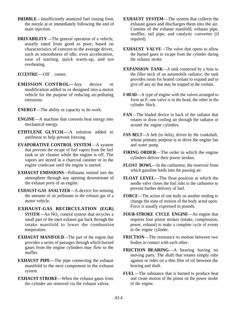
DRIBBLE—Insufficiently atomized fuel issuing fromthe nozzle at or immediately following the end ofmain injection.
DRIVABILITY —The general operation of a vehicle,usually rated from good to poor; based oncharacteristics of concern to the average driver,such as smoothness of idle, even acceleration,ease of starting, quick warm-up, and notoverheating.
ECCENTRIC—Off center.
EMISSION CONTROL—Any device ormodification added to or designed into a motorvehicle for the purpose of reducing air-pollutingemissions.
ENERGY—The ability or capacity to do work.
ENGINE—A machine that converts heat energy intomechanical energy.
ETHYLENE GLYCOL—A solution added toantifreeze to help prevent freezing.
EVAPORATIVE CONTROL SYSTEM—A systemthat prevents the escape of fuel vapors from the fueltank or air cleaner while the engine is off. Thevapors are stored in a charcoal canister or in theengine crankcase until the engine is started.
AI-4
EXHAUST EMISSIONS—Pollutants emitted into theatmosphere through any opening downstream ofthe exhaust ports of an engine.
EXHAUST-GAS ANALYZER—A device for sensingthe amounts of air pollutants in the exhaust gas of amotor vehicle.
EXHAUST-GAS RECIRCULATION (EGR)SYSTEM—An NOx control system that recycles asmall part of the inert exhaust gas back through theintake manifold to lower the combustiontemperature.
EXHAUST MANIFOLD—The part of the engine thatprovides a series of passages through which burnedgases from the engine cylinders may flow to themuffler.
EXHAUST PIPE—The pipe connecting the exhaustmanifold to the next component in the exhaustsystem.
EXHAUST STROKE—When the exhaust gases fromthe cylinder are removed via the exhaust valves.
EXHAUST SYSTEM—The system that collects theexhaust gases and discharges them into the air.Consists of the exhaust manifold, exhaust pipe,muffler, tail pipe, and catalytic converter (ifrequired).
EXHAUST VALVE—The valve that opens to allowthe burned gases to escape from the cylinder duringthe exhaust stroke.
EXPANSION TANK—A tank connected by a hose tothe filler neck of an automobile radiator; the tankprovides room for heated coolant to expand and togive off any air that may be trapped in the coolant.
F-HEAD—A type of engine with the valves arranged toform an F; one valve is in the head, the other in thecylinder block.
FAN—The bladed device in back of the radiator thatrotates to draw cooling air through the radiator oraround the engine cylinders.
FAN BELT—A belt (or belts), driven by the crankshaft,whose primary purpose is to drive the engine fanand water pump.
FIRING ORDER—The order in which the enginecylinders deliver their power strokes.
FLOAT BOWL—In the carburetor, the reservoir fromwhich gasoline feeds into the passing air.
FLOAT LEVEL—The float position at which theneedle valve closes the fuel inlet to the carburetor toprevent further delivery of fuel.
FORCE—The action of one body on another tending tochange the state of motion of the body acted upon.Force is usually expressed in pounds.
FOUR-STROKE CYCLE ENGINE—An engine thatrequires four piston strokes (intake, compression,power, exhaust) to make a complete cycle of eventsin the engine cylinder.
FRICTION—The resistance to motion between twobodies in contact with each other.
FRICTION BEARING—A bearing having nomoving parts. The shaft that rotates simply rubsagainst or rides on a thin film of oil between thebearing and shaft.
FUEL—The substance that is burned to produce heatand create motion of the piston on the power strokeof the engine.

FUEL FILTER—A device located in the fuel systemthat removes dirt and other contaminates from thefuel passing through.
FUEL GAUGE—The gauge that indicates to theoperator the height of the fuel level in the tank.
FUEL INJECTION—A fuel delivery system thatsprays fuel either directly into the cylinders or intothe intake manifold just ahead of the cylinders.
FUEL INJECTION TUBING—The tube connectingthe injection pump to the nozzle holder assembly.
FUEL INJECTOR—A device in a diesel engine fuelsystem for injecting fuel into the cylinder.
FUEL LINE—The pipe or tube through which fueltravels from the tank to other components withinthe fuel system.
FUEL PUMP—The electrical or mechanical device inthe fuel system which forces fuel from the fuel tankto the carburetor or fuel injection system.
FUEL PUMPHOUSING—The main casing into or towhich are assembled all the components of theinjection pump, and may accommodate thecamshaft in the case of camshaft pumps; or thecamshaft or driveshaft in the case of distributor typepumps.
FUEL TANK—The metal tank that serves as a storageplace for fuel.
FULL-FLOATING PISTON—A piston pin free toturn in the piston boss of the connecting rod eye.
FULL THROTTLE—Wide-open throttle positionwith accelerator pressed all the way down to thefloorboard
GASOLINE—A liquid blend of hydrocarbons,obtained from crude oil; used as the fuel in mostautomotive engines.
GASOLINE ENGINE—An engine having its pistondriven by the explosions of a mixture of air andgasoline vapor ignited by an electric spark
GASTIGHT —Constructed or arranged so that gas willnot enter or escape an enclosed space underspecified conditions.
GEAR TRAIN—A drive mechanism consisting of agroup of gear that mesh together to operate anengine and its accessories.
GLOW PLUG—A small electric heater installed in theprecombustion chamber of diesel engine to preheatthe chamber for easier starting in cold weather.
GOVERNOR—A device that controls, or governs,another device, usually on the basis of speed orload.
HEAT-CONTROL VALVE—In the engine, athermostatically operated valve in the exhaustmanifold; diverts heat to the intake manifold towarm it before the engine reaches normal operatingtemperature.
HONE—A tool/process for enlarging cylinders orcylinder lines to precise tolerances; also used forcontrolling finishes.
HORSEPOWER—A measure of a definite amount ofpower; 550 foot-pound per second.
HYDRAULIC GOVERNOR—A mechanicalgovernor having a hydraulic servo-booster toincrease output force.
HYDRAULIC HEAD ASSEMBLY—The assemblycontaining the pumping, metering, and distributingelements (and may include the delivery valve) fordistributor-type pumps.
HYDRAULIC VALVE TAPPET—A valve tappetthat, by means of hydraulic pressure, maintains zerovalve clearance so that valve noise is reduced.
HYDROCARBON (HC)—A compound containingonly carbon and hydrogen atoms, usually derivedfrom fossil fuels such as petroleum, natural gas, andcoal; an agent in the formation of photochemicalsmog. Gasoline is a blend of liquid hydrocarbonsrefined from crude oil.
HYDROGEN (H)—A colorless, odorless, highlyflammable gas whose combustion produces water;the simplest and lightest element.
HYDROMETER—A device to determine the specificgravity (roughly the heaviness) of a liquid. Thisdetermination indicates the freezing point of thecoolant in the cooling system.
I-HEAD—A type of engine with the valves located inthe cylinder head.
INDICATED HORSEPOWER—A measurement ofengine power based on power actually developed inthe engine cylinders.
AI-5
IDLE-MIXTURE SCREW—The adjustment screw(on some carburetors) that can be turned in or out tolean or enrich the idle mixture.
IDLE SPEED—The speed, or rpm, at which the engineruns when the accelerator pedal is fully released andthere is no load on the engine.
IGNITION-COMPRESSION —When the heatgenerated by compression in an internalcombustion engine ignites the fuel (as in a dieselengine).
IGNITION-SPARK—When the mixture of air andfuel in an internal combustion engine is ignited byan electric spark (as in a gasoline engine).
IGNITION TIMING—Refers to the timing of thespark at the spark plug as related to the piston in theengine cylinder.
INJECTION/IGNITION—When the piston nears thetop of its stroke, fuel admitted under pressure issprayed into the cylinder. The fuel ignites due to theheat in the cylinder.
INJECTION PUMP—The device which meters thefuel and delivers it under pressure to the nozzle andholder assembly.
INJECTION PUMP ASSEMBLY—A completeassembly consisting of the fuel pump proper,together with additional units such as governor, fuelsupply pump, and additional optional devices,when these are assembled with the injection pumpto form a unit.
INJECTION TIMING—The matching of the pumptiming mark, or the injector timing mechanism, tosome index mark on an engine component, suchthat injection will occur at the proper time withreference to the engine cycle.
INJECTOR—The mechanism, including nozzle, thatinjects fuel into the engine combustion chamber ondiesel engines.
IN-LINE ENGINE—An engine in which the cylindersare arranged in one straight line.
IN-LINE PUMP—An injection pump with two ormore pumping elements arranged in line, eachpumping element serving one engine cylinder only.
INTAKE MANIFOLD—That component of theengine that provides a series of passages to allowthe air-fuel mixture to flow to the engine cylinders.
INTAKE STROKE—The piston stroke from top deadcenter to bottom dead center during which theintake valve is open and the cylinder receives acharge of air-fuel mixture.
INTAKE VALVE—The valve in the engine that isopened during the intake stroke to permit theentrance of the air-fuel mixture into the cylinder.
INTERNAL COMBUSTION ENGINE—An enginein which the fuel is burned inside the engine, asopposed to an external combustion engine wherethe fuel is burned outside the engine, such as asteam engine.
JOURNAL—Serves as the point of support and thecenter of rotation for the shaft. That part of the shaftthat is prepared to accept a bearing (connecting rod,main bearing).
KNOCK—A heavy metallic engine sound that varieswith engine speed; usually caused by a loose orworn bearing; name also used for detonation,pinging, and spark knock. See DETONATION.
L-HEAD—A type of engine with the valves located inthe cylinder block.
LAP—To work two surfaces together with abrasiveuntil a very close fit is produced; to polish.
LASH—The clearance or play between adjacentmovable mechanical parts. See VALVE LASH.
LEAN MIXTURE—A air-fuel mixture that has a highproportion of air and a low proportion of fuel.
LUBRICATION SYSTEM—The system in theengine that supplies the engine with lubricating oilto prevent contact between any two moving metalsurfaces.
MANIFOLD—A device with several inlet or outletpassageways through which a gas or liquid isgathered or distributed. See INTAKE MANIFOLDand EXHAUST MANIFOLD.
MECHANICAL EFFICIENCY—In an engine, theratio between brake horsepower and indicatedhorsepower.
MECHANICAL GOVERNOR—A speed sensitivedevice of the centrifugal type, which controls theinjection pump delivery sole by mechanical means.
MICROMETER—A measuring device that measuresaccurately such dimensions as shaft or borediameter or thickness of an object.
AI-6
MICROPROCESSOR—The small, on-board solid-state electronic device that acts as the centralprocessing unit. Sensors provide input informationwhich the microprocessor uses to determine thedesired response (in any) as an output signal.
MUFFLER—In the exhaust system, a device throughwhich the exhaust gases must pass and whichreduces the exhaust noise.
MULTIPLE-POINT INJECTION—A gasoline fuelinjection system in which only air enters the intakemanifold. As the air approaches the intake valve, aninjection valve opens in the intake port, sprayingfuel into the airstream. Also called port injection.
MULTIPLE-VISCOSITY OIL—An engine oil thathas a low viscosity when cold (for easier starting)and a higher viscosity when hot (to provideadequate engine lubrication).
NEEDLE VALVE—A small, tapered, needle-pointedvalve that can move into or out of a seat to close oropen the passage through it. Used to control the fuellevel in the carburetor float bowl.
NITROGEN (N)—A colorless, tasteless, odorless gasthat constitutes 78 percent of the atmosphere byvolume and is a part of all living substances.
NITROGEN OXIDES (NOx)—Any chemicalcompound of nitrogen and oxygen; a basic airpollutant. Automotive exhaust emissions levels ofnitrogen oxides are limited by law.
NOZZLE—The opening or jet, through which fuel orair passes as it’s discharged. Also, the assembly ofparts employed to atomize and deliver fuel to theengine.
NOZZLE AND HOLDER ASSEMBLY—Thecomplete apparatus which injects the pressurizedfuel into the combustion chamber.
NOZZLE TIP—The extreme end of the nozzle bodycontaining the spray holes.
OCTANE RATING—A measure of the antiknockproperties of gasoline. The higher the octane rating,the more resistant the gasoline is to spark knock ordetonation.
OIL—A liquid lubricant, usually made from crude oiland used for lubrication between moving parts.
OIL CLEARANCE—The space between the bearingand the shaft rotating within it.
OIL CONTROL RINGS—The lower ring or rings ona piston; designed to prevent excessive amounts ofoil from working up into the combustion chamber.
OIL COOLER—A small radiator that lowers thetemperature of oil flowing through it.
OIL FILTER—A filter that removes impurities fromthe engine oil passing through it.
OIL GALLERY—A pipe or drilled passageway in theengine used to transport oil from one area toanother.
OIL-LEVEL GAUGE—The dipstick that is removedand inspected to check the level of the oil in thecrankcase of an engine.
OIL PAN—The lower part of the crankcase in which areservoir of oil is maintained.
OIL-PRESSURE INDICATOR—A gauge thatindicates (to the operator) the oil pressure in thelubricating system, or a light that comes on if the oilpressure drops too low.
OIL PUMP—A device that forces oil from the oil panto the moving parts of an engine.
OIL SLINGER—A device mounted to a revolvingshaft such that any oil passing that point will bethrown outward where it will return to the point oforigin.
OVERHEAD CAMSHAFT—A camshaft located inthe cylinder head where the cam lobes are in directcontact with the rocker arms.
OXYGEN—A colorless, tasteless, odorless, gaseouselement that makes up about 21 percent of the air.Capable of combining rapidly with all elementsexcept the inert gases in the oxidation processcalled burning.
PARTICLE—A very small piece of metal, dirt, orother impurity which may be contained in the air,fuel, or lubricating oil used in an engine.
PASSAGE—A small hole or gallery in an assembly orcasting through which air, coolant, fuel, or oilflows.
PCV VALVE—The valve that controls the flow ofcrankcase vapors in accordance with ventilationrequirements for different speeds and loads.
PETROLEUM—The crude oil from which gasoline,lubricating oil, and other such products are refined.
AI-7
PHOTOCHEMICAL SMOG—Smog caused byhydrocarbons and nitrogen oxides reactingphotochemically in the atmosphere. The reactionstake place under low wind velocity, bright sunlight,and an inversion layer in which the air mass istrapped Can cause eye and lung irritation
PING—Engine spark knock or detonation that occursusually during acceleration. Caused by excessiveadvance of ignition timing or low-octane fuel.
PISTON—A cylindrical plug that slides up and downin the cylinder and is joined to the connectingrod.
PISTON BOSS—The reinforced area around thepiston-pin bore.
PISTON CROWN—The top or head of the piston.
PISTON DISPLACEMENT—The volume of airmoved or displaced by the piston as the pistonmoves from BDC to TDC.
PISTON HEAD—The portion of the piston above thetop ring.
PISTON LANDS—The spaces in the piston betweenthe ring grooves.
PISTON PIN-A cylindrical pin that passes throughthe piston bore and joins the connecting rod to thepiston.
PISTON RING—A split ring (expansion type) placedin a groove of the piston to seal the space betweenthe piston and the cylinder wall.
PISTON-RING END GAP—The clearance betweenthe ends of the piston ring.
PISTON-RING GROOVE—The grooves cut in thepiston into which the piston rings are fitted.
PISTON-RING SIDE CLEARANCE—Theclearance between the side of the ring and the ringlands.
PISTON SKIRT—The portion of the piston that isbelow the piston bore.
PISTON STROKE—The distance that a piston movesbetween its limits of travel.
POLLUTANT—Any substance that adds to thepollution of the atmosphere. In a vehicle, any suchsubstance in the exhaust gas from the engine orescaping from the fuel tank or air cleaner.
POSITIVE CRANKCASE VENTILATION(PCV)—A crankcase ventilation system; usesintake manifold vacuum to return the crankcasevapors and blow-by gases to the intake manifold tobe burned, thereby preventing their escape into theatmosphere.
POWER—The rate of doing work or the rate forexpanding energy. The unit for mechanical poweris horsepower.
PRONY BRAKE—A device using a friction brake tomeasure horsepower.
PRECISION INSERT BEARING—A precision typeof bearing consisting of an upper and lower shell.
PRECOMBUSTION CHAMBER—In someengines, a separate small combustion chamberwhere combustion begins.
PREIGNITION—Ignition of the air-fuel mixture inthe combustion chamber by some unwanted means,before the ignition spark occurs at the spark plug.
PRESSURE —The amount of force distributed overeach unit of area. Pressure is expressed in poundsper square inch (psi), inches of mercury, and otherunits.
PRESSURE CAP—A radiator cap with valves whichcauses the cooling system to operate under pressureat a higher and more efficient temperature.
PRESSURIZE —To apply more than atmosphericpressure to a gas or liquid.
PSI—Pound per square inch; usually to indicatepressure of a liquid or gas.
PUSHRODS—A special rod used to transit the motionof the cam and the lifter to the rocker on the cylinderhead.
RADIAL ENGINE—An engine with each cylinderlocated on a radius of a circle and with all cylindersdisposed around a common crankshaft.
RADIATOR—In the cooling system, the device thatremoves heat from coolant passing through it;receives hot coolant from the engine and sends thecoolant back to the engine at a lower temperature.
RADIATOR CAP—The cap placed on the radiatorfiller neck.
RATIO—The value obtained by dividing one numberby another, indicating their relative proportions.
AI-8

RECIPROCATING —Moving back and forth; as apiston reciprocating in a cylinder.
RELIEF VALVE—A valve that opens when a presetpressure is reached. This relieves or preventsexcessive pressure.
REVOLUTION —A term to describe a 360° circularmotion of the crankshaft.
RICH MIXTURE—An air-fuel mixture that has a lowproportion of air and a high proportion of fuel.
ROCKER ARM—A device that rocks or pivots on therocker arm shaft as the cam rotates, causing thevalve to open.
ROCK POSITION—The piston and connecting rodposition (top or bottom dead center) at which thecrank can rock or rotate a few degrees withoutappreciable movement of the piston.
ROD CAP—The lower part of a connecting rod thatcan be taken off by removing bolts or nuts so the rodcan be detached from the crankshaft.
SAE—Society of Automotive Engineers.
SCAVENGING-A cleaning or blowing out action inreference to exhaust gases.
SEMIFLOATING PISTON PIN—A piston pin inwhich the ends of the pin are free to move in thepiston bearings of the bosses.
SHROUD—A hood placed around an engine fan toimprove air flow.
SLEEVE METERING—A system of metering fueldelivery by incorporating a movable sleeve withwhich port opening and/or port closing iscontrolled.
SMOG—A term coined from the words "smoke" and"fog." First applied to the foglike layer that hangs inthe air under certain atmospheric conditions;generally used to describe any condition of dirty airand/or fumes or smoke.
SOHC—Single overhead camshaft.
SPILL VALVE—A valve used to end injection at acontrollable point on the pumping stroke byallowing fuel to escape from the pumping chamber.
SPRING RETAINER—The piece of metal that holdsthe valve spring in place, and is itself locked inplace by the valve spring retainer locks.
STATIONARY PARTS—The main parts of an enginethat do not move, but provide support
STROKE—The movement, or the distance of themovement, in either direction, of the piston travel inan engine.
SUPERCHARGER—In the intake system of theengine, a pump that pressurizes the incoming air orair-fuel mixture. This increases the amount of fuelthat can be burned, increasing engine power. If thesupercharger is driven by the engine exhaust gas, itis called a turbocharger.
SUPPLY PUMP—A pump for transferring the fuelfrom the tank and delivering it to the injectionpump.
TANK SENDING UNIT—A device in the fuel tankthat provides indication of fuel level for instrumentpanel gauge.
TDC (TOP DEAD CENTER)—The position of areciprocating piston at its uppermost point oftravel.
TEMPERATURE INDICATOR—A gauge thatindicates to the operator the temperature of theengine coolant, or a light that comes on if thecoolant gets too hot.
THERMAL EFFICIENCY—The ratio between thepower output and the energy in the fuel burned toproduce the output.
THERMOSTAT—A device for automatic regulationof temperature; usually contains a temperature-sensitive element that expands or contracts toopen and close off the flow of air, a gas, or aliquid.
THERMOSTATIC SWITCH—A switch that isturned on or off by temperature change.
THRUST—A force tending to push a body out ofalignment, A force exerted endwise through amember upon another member.
THRUST BEARING—Bearing that limits the axial(longitudinal) movement of the shaft.
TIMING DEVICE—A device responsive to enginespeed and/or load to control the timed relationshipbetween injection cycle and engine cycle.
TORQUE—A force that produces a turning or twistingeffort; measured in pound-feet.
AI-9

TORQUE CONTROL—A device which modifies themaximum amount of fuel injected into the enginecylinders at speeds below rated speed to obtain thedesired torque output.
TURBOCHARGER—An exhaust driven compressorthat forces air into the engine.
TWO-STROKE CYCLE ENGINE—An internalcombustion engine requiring but two piston strokesto complete the cycle of events that produce power.
UNIT FUEL INJECTOR—An assembly whichreceives fuel under supply pressure and is thenactuated by an engine mechanism to meter andinject the charge of fuel to the combustion chamberat high pressure and at the proper time.
UNIT PUMP—An injection pump containing noactuating mechanism to operate the pumpingelement or elements.
VALVE—A mechanism that can be opened or closed tocontrol or stop the flow of a liquid, gas, or vaporfrom one space to another.
VALVE-ACTUATING MECHANISM—A group ofparts that work together to receive power from thedrive mechanism (camshaft) and transmit thatpower to the engine valves.
VALVE GUIDE—A hollow shaft pressed into thecylinder head to keep the valve in proper alignment.
VALVE LASH—Clearance between the top of thevalve stem and the valve-lifting mechanism.
VALVE LIFT—The distance a valve moves from thefully closed to the fully open position
VALVE OVERLAP—The period of crankshaftrotation during which both the intake and exhaustvalves are open. It is measured in degrees.
VALVE REFACING MACHINE—A specialmachine used to resurface the face and extend thelife of a valve.
VALVE RETAINER—A device designed to lock thevalve-spring retainer to the valve stem.
VALVE ROTATOR—A mechanical device locked tothe end of the valve stem (used in place of a valvespring retainer) that forces the valve to rotate about5° with each rocker arm action.
VALVE SEAT—The surface, normally curved, againstwhich the valve disk's operating face comes to rest
to provide a seal against leakage of liquid, gas, orvapor.
VALVE SEAT INSERT—A metal ring inserted intothe valve seat, made of special metal that canwithstand engine operating temperatures.
VALVE SPRING—The compression-type spring thatcloses the valve when the valve-operating camassumes a closed-valve position.
VAPORIZATION —A change of state from liquid tovapor gas, by evaporation or boiling; a general termincluding both evaporation and boiling.
VAPOR LOCK—A condition in the fuel system inwhich gasoline vaporizes in the fuel line or fuelpump; bubbles of gasoline vapor restrict or preventfuel delivery to the carburetor.
VARIABLE SPEED FAN—An engine fan that willnot exceed a predetermined speed or will rotateonly as fast as required to prevent engineoverheating.
VENTURI—In the carburetor, a narrowed passagewayor restriction that increases the velocity of air mov-ing through it, produces the vacuum responsible forthe discharge of fuel from the fuel nozzle.
VIBRATION —An unceasing back and forthmovement over the same path; often with referenceto the rapid succession of motions of parts of anelastic body.
VIBRATION DAMPER—A weighted device that isattached to the engine crankshaft at the end oppositeits power output. Its purpose is to absorb enginevibration.
VISCOSITY—The resistance to flow exhibited by aliquid. A thick oil has a greater viscosity than a thinoil.
VOLATILITY—A measure of the ease with which aliquid vaporizes. Volatility has a direct relationshipto the flammability of a fuel.
VOLUME—The amount of air in the combustionspace of an engine cylinder.
VOLUMETRIC EFFICIENCY—The ratio betweenthe amount of air-fuel mixture that actually entersan engine cylinder and the amount that could enterunder ideal conditions.
V-TYPE ENGINE—An engine with two banks ofcylinders set at an angle to each other in the shape ofa V.
AI-10
WASTE GATE—A control device on a turbochargerto limit boost pressure, thereby preventing engineand turbocharger damage.
WATER JACKETS—The spaces between the innerand outer shells of the cylinder block and headthrough which coolant circulates.
WATER PUMP—In the cooling system, the devicethat circulates coolant between the engine waterjackets and the radiator.
WORK—The result of a force acting againstopposition to produce motion. It is measure interms of the product of the force and the distance itacts.
AI-11

APPENDIX II
ANSWER KEY
CHAPTER 1 - TECHNICAL ADMINISTRATION
MAINTENANCE ADMINISTRATION
Q1. maintenance supervisor
Q2. 40 working days
Q3. P-300
Q4. one
Q5. indirect labor
MAINTENANCE SUPPORT
Q6. H level
Q7. 1250-2
Q8. 24 hours
Q9. PM groups
Q10. maintenance supervisor
CHAPTER 2 - PRINCIPLES OF AN INTERNALCOMBUSTION ENGINE
INTERNAL COMBUSTION ENGINE
Q1. rotary motion
Q2. fuel, air, ignition
Q3. four (cylinder, piston, connecting rod, and crankshaft)
Q4. scavenging
CLASSIFICATION OF ENGINES
Q6. fuel, lubrication, electrical, cooling, and exhaust systems
Q7. horizontal opposed
Q8. 180°
Q9. I-head
Q10. F-head
AII-1
ENGINE MEASUREMENTS AND PERFORMANCE
Q11. one foot
Q12. prony brake
Q13. friction
Q14. mechanical efficiency
Q15. liters
CHAPTER 3 - CONSTRUCTION OF AN INTERNALCOMBUSTION ENGINE
ENGINE CONSTRUCTION
Q1. cylinder sleeves or liners
Q2. wet- and dry-type
Q3. cup and disk
Q4. crankcase
Q5. scavenging
Q6. manifold heat control valve
Q7. synthetic rubber and wick
Q8. head, skirt, ring grooves, and lands
Q9. anchored, semi-floating, full-floating
Q1O. provide a seal between piston and cylinder wall, contains lubricating oil,and provides a solid bridge to conduct heat from piston to cylinder wall
Q11. crankshaft
Q12. camshaft, followers, pushrods, and rocker arms
Q13. mushroom, semi-tulip, and tulip
Q14. stellite
Q15. umbrella and O ring
ENGINE ADJUSTMENTS AND TEST
Q16. spring squareness, spring free height, and spring tension
Q17. normal operating temperature
Q18. piston rings and cylinders may be worn and leaking pressure
Q19. incorrect timing
Q20. leaking intake valves
AII-2

CHAPTER 4 - GASOLINE FUEL SYSTEMS
GASOLINE FUEL SYSTEM
Q1. antiknock
Q2. octane rating
Q3. fuel neck restrictor
Q4. wet- and dry-type
PRINCIPLES OF CARBURETION
Q5. float, idle, off-idle, acceleration, high speed, full power, choke
Q6. float
Q7. throttle return dashpot
Q8. manifold pressure sensor (MAP)
GASOLINE FUEL INJECTION
Q9. timed injection
Q10. crankshaft postion sensor
Q11. throttle positioner
EXHAUST AND EMISSIONS CONTROL SYSTEMS
Q12. hydrocarbons, carbon monoxide, and oxides of nitrogen
Q13. platinum and palladium
Q14. monolithic
Q15. coolant temperature switch
CHAPTER 5 - DIESEL FUEL SYSTEMS
DIESEL FUEL SYSTEM
Q1. 2D
Q2. pour point
Q3. cleaniness
Q4. spherical
Q5. ischronous
Q6. electronic governor
Q7. hydraulic power piston
Q8. six
Q9. 2 to 2 1/2 inches
AII-3
METHODS OF INJECTION
Q10. meter, inject, time, atomize, and create pressure
Q11. 9 gallons per minute
Q12. front end of the engine camshaft
Q13. low side of the injection pump housing
Q14. drive shaft, distributor rotor, transfer pump
Q15. maximum outward travel of the plungers
Q16. spring-loaded ballcheck return fitting
Q17. 65 to 75 psi
Q18. unit type
Q19. one
Q20. AFC device
Q21. PT pump is not timed to the engine
Q22. oil temperature sensor
Q23. 140 psi
Q24. control valve
Q25. multifuel
Q26. fuel density compensator
SUPERCHARGERS AND TURBOCHARGERS
Q27. intercooler
Q28. sealing rings
COLD WEATHER STARTING AIDS
Q29. manifold flame heater
Q30. extreme emergencies
DIESEL FUEL SYSTEM MAINTENANCE
Q31. daily
Q32. clean work area
GENERAL TROUBLESHOOTING
Q33. 3 to 5 minutes
Q34. blue
Q35. push down and hold the injector follower with a large screwdriver
AII-4
CHAPTER 6 - COOLING AND LUBRICATING SYSTEM
COOLING SYSTEMS
Q1. air-cooled
Q2. radiator
Q3. downflow and crossflow
Q4. bottom of the cap
Q5. thermostatic
Q6. thermostat
Q7. 50/50
Q8. fast, reversing, and chemical
Q9. hydrometer and refractometer
Q10. hand-operated air pump
LUBRICATING SYSTEM
Q11. viscometer
Q12. by the letter W (10W30)
Q13. American Petroleum Institue (API)
Q14. SG
Q15. full-flow and bypass
Q16. splash, combination splash and force-feed, force-feed, and full force-feed
Q17. splash
Q18. full forced-feed
Q19. micrometer and small hole gauge
AII-5


APPENDIX III
REFERENCES USED TO DEVELOPTHIS TRAMAN
NOTE: The following references were current at the time thisTRAMAN was published, but you should be sure you have thecurrent editions.
1988 C-K Pick-Up Truck Service Manual, Chevrolet Motor Division, GeneralMotors Corporation, Detroit, MI, 1986.
1989 Medium/Heavy-Duty Truck, Shop Manual, Ford Motor Company, Dearborn,MI, 1988.
Brady, Robert N., Diesel Fuel Systems, Prentice-Hall Inc., Englewood Cliffs, NJ,1981.
Brady, Robert N., Heavy-Duty Truck Fuel Systems, Prentice-Hall Inc., EnglewoodCliffs, NJ, 1991.
Duffy, James E., Modern Automotive Mechanics, Goodheart-Willcox CompanyInc., South Holland, IL, 1990.
Duffy, James E., Modern Automotive Technology, Goodheart-Willcox CompanyInc., South Holland, IL, 1994.
Engineman Fundamentals, NAVEDTRA 12170, Naval Education and TrainingProfessional Development and Technology Center, Pensacola, FL, 1996.
Equipment Operator; Basic, NAVEDTRA 12535, Naval Education and TrainingProfessional Development and Technology Center, Pensacola, FL, 1994.
Management of Civil Engineering Support Equipment, NAVFAC P-300, NavalFacilities Engineering Command, Alexandria, VA, 1997.
NMCB Equipment Management, COMSECOND/COMTHIRDNCBINST11200.1, Commander, Second Naval Construction Brigade and Commander,Third Naval Construction Brigade, Norfolk, VA and Pearl Harbor, HI, 1994.
Principles of Automotive Vehicles, TM 9-8000, Department of the Army,Washington, DC, 1988.
AIII-1

INDEX
A
Acceleration system, 4-19, 4-20Air cleaner, 4-14, 4-15Air-cooled system, 6-2 - 6-4
baffles and fins, 6-3fan and shroud, 6-3maintaining the air-cooled system, 6-3, 6-4
Air-fuel mixture ratio, 4-2lean, 4-2rich, 4-2
Air injection system, 4-42Air in fuel, 5-51American bosch fuel injection system, 5-41 - 5-45
fuel density compensator, 5-43 - 5-45fuel pump, 5-41, 5-42nozzle operation, 5-43types of nozzles, 5-43
Arrangement of cylinders, 2-10, 2-11horizontal opposed, 2-11in-line, 2-10radial, 2-11v-type, 2-10
Arrangement of valves, 2-11, 2-12F-head, 2-11, 2-12I-head, 2-11L-head, 2-11T-head. 2-12
B
Basic engine strokes, 2-3 - 2-5compression stroke, 2-5exhaust stroke, 2-5intake stroke, 2-5power stroke, 2-5
Bearing characteristics, 3-42Bearings, engine, 3-40, 3-41Bearing lubrication, 3-41, 3-42Bearing materials, 3-42
C
Camshaft, 3-30Carburetor, 4-17 - 4-28
acceleration system, 4-19 - 4-2 1choke system, 4-24 - 4-28float system, 4-17full power system, 4-23, 4-24high-speed system, 4-21 - 4-23
Carburetor—Continuedidle system, 4-19off-idle system, 4-19
Carburetor accessories, 4-28 - 4-31altitude compensator, 4-30fast idle solenoid, 4-28hot idle compensator, 4-30throttle return dashpot, 4-28, 4-29
Carburetor troubles, 4-31, 4-32Catalytic converters, 4-41, 4-42Caterpillar fuel injection systems, 5-16 - 5-22
automatic timing advance unit, 5-19fuel injection nozzle, 5-21, 5-22governor, 5-21governor action, 5-18, 5-19scroll-metering fuel system, 5-19, 5-21sleeve-metering fuel system, 5-16 - 5-18transfer pump, 5-20
Classification of engines, 2-8 - 2-13Cleaning injectors, 5-51, 5-52Cold weather starting, 5-49, 5-50Combustion chamber design, 5-4 - 5-8
open, 5-5precombustion, 5-5, 5-6spherical (hypercycle), 5-6 - 5-8turbulence, 5-6
Compression test, 3-45, 3-46Computerized controlled carburetors, 4-30, 4-31Connecting rods, 3-23, 3-24Continuous fuel injection, 4-36, 4-37Cooling system test, 6-16 - 6-18
combustion leak test, 6-17cooling system pressure test, 6-16, 6-17engine fan test, 6-18thermostat test, 6-17, 6-18
COSAL arrangement, 1-19, 1-21Cost control supervisor, 1-2Crankcase, 3-6, 3-7Crankshaft, 3-24 - 3-28Crew leader, 1-2Cummins fuel systems, 5-33 - 5-41
celect fuel system, 5-36 - 5-39celect system operation, 5-39 - 5-41fuel pump, 5-34, 5-35injectors, 5-35, 5-36pressure-time system, 5-33, 5-34
Cylinder head, 3-7 - 3-9Cylinder leakage test, 3-47, 3-48Cylinder liners, 3-5
INDEX-1
D
Detroit diesel unit injection system, 5-26 - 5-33equalizing injectors, 5-31, 5-32fuel pump, 5-28, 5-29governor, 5-32, 5-33injector, 5-29, 5-30injector timing, 5-30, 5-31
Depot maintenance, 1-3Development of power, 2-2, 2-3Diesel fuel, 5-1 - 5-4
cetane number, 5-3cleanliness and stability, 5-4cloud and pour point, 5-4diesel fuel oil grades, 5-3sulfur content, 5-4viscosity, 5-4volatility, 5-3
Diesel fuel system components, 5-13, 5-14fuel filters, 5-13.5-14gauges, 5-13water separators, 5-14supply pump, 5-14tanks and caps, 5-13
Diesel fuel system maintenance, 5-51, 5-52Direct turnover clerk, 1-2Dirt in fuel system, 5-51Distributor-type fuel injection system, 5-21 - 5-26
governor, 5-25, 5-26injection pump, 5-21 - 5-23injection pump accessories, 5-23, 5-24nozzle, 5-26
DTO log, 1-24, 1-26
E
Engine adjustments and testing, 3-43 - 3-48compression test, 3-45, 3-46cylinder leakage test, 3-47, 3-48vacuum gauge test, 3-46, 3-47valve adjustment, 3-43 - 3-45
Engine comparsion, 2-8, 2-9Engine construction, 3-1 - 3-43Engine cooling systems, 6-1 - 6-21Engine cylinder block, 3-1 - 3-7Engine lubrication system, 6-21 - 6-37
engine oil, 6-22, 6-23lubricating (oil) system components, 6-24 - 6-31lubricating system maintenance, 6,35, 6,36lubricating system problem diagnosis, 6-34,
6-35purposes of lubrication, 6-22types of lubricating (oil) systems, 6-32 - 6-34
Engine measurements and performance, 2-13 - 2-22definitions, 2-13 - 2-18engine performance, 2-19linear measurements, 2-18, 2-19timing, 2-19 - 2-22
Engine oil, 6-22 - 6-24oil viscosity and measurements, 6-22, 6-23oil service rating, 6-24
Equipment history jackets, 1-15Ether, 5-50Exhaust and emission control systems, 4-38 - 4-48Exhaust gas recirculation, 4-45, 4-46Exhaust manifold, 3-10, 4-39Exhaust smoke color, 5-52, 5-53Exhaust stroke, 2-5
F
Flywheel, 3-29Followers, 3-30 - 3-32
hyrdaulic, 3-31, 3-32mechanical, 3-3 1
Four-stroke-cycle engine, 2-3 - 2-5Fuel evaporation control, 4-46 - 4-48Fuel injection, 5-15, 5-16
atomization of fuel, 5-15, 5-16creating pressure, 5-16injection control, 5-15metering, 5-15timing, 5-15
Frictional horsepower, 2-16
G
Gaskets, 3-12cylinder head, 3-12exhaust manifold, 3-12intake manifold, 3-12oil pan gasket, 3-12
Gasoline, 4-1Gasoline combustion, 4-2, 4-3
abnormal, 4-2, 4-3normal, 4-2
Gasoline fuel injection, 4-32 - 4-38continuous, 4-36, 4-37throttle body, 4-37, 4-38timed, 4-32 - 4-36
Gasoline fuel system components, 4-3 - 4-15filters, 4-7, 4-8gauges, 4-5 - 4-7lines, 4-13, 4-14pump, 4-8 - 4-13tank, 4-4, 4-5
General troubleshooting, 5-52 - 5-54
INDEX-2
Glow plugs, 5-49Governors, 5-8 - 5-12
electronic, 5-12hydraulic, 5-11mechanical, 5-9 - 5-11terms, 5-12, 5-13types of governors, 5-9
I
Inspections, maintenance,accident, 1-6deadline, 1-6operator, l-5preventive maintenance, 1-5, 1-6
Inspector, 1-2Intake manifold, 3-10 - 3-12Intake stroke, 2-5Intermediate maintenance, 1-3
L
Labor reporting, 1-15, 1-18Linear measurements, 2-18, 2-19Liquid-cooled system, 6-4 - 6-2 1
coolants and antifreeze, 6-14expansion (recovery) tank, 6-13fan and shroud, 6-8 - 6-10radiator, 6-5, 6-6radiator hoses, 6-6radiator pressure cap, 6-6, 6-7temperature gauge and warning light, 6-14thermostats, 6-10 - 6-13water jacket, 6-10water pump, 6-7, 6-8
Lubrication (oil) system components, 6-24 - 6-31oil filter, 6-27 - 6-30oil galleries, 6-30oil level gauge, 6-25oil pan, 6-24, 6-25oil pickup and strainer, 6-27oil pressure gauge, 6-30, 6-31oil pressure warning light, 6-30oil pump, 6-25, 6-26oil temperature regulator, 6-31, 6-32
Lubrication system maintenance, 6-35, 6-36oil and filter change, 6-35, 6-36oil pump service, 6-36pressure relief valve service, 6-36
Lubrication system problem diagnosis, 6-34, 6-35high oil consumption, 6-34high oil pressure, 6-35indicator or gauge problems, 6-35low oil pressure, 6-35
M
Maintenance administration, 1-1 - 1-18equipment history jackets, 1-15labor reporting, 1-15 - 1-18maintenance categories, 1-2, 1-3maintenance inspections, 1-5, 1-6maintenance organization, 1-1, 1-2maintenance scheduling, 1-3 - 1-5PM record cards, 1-6 - 1-8repair orders, 1-8 - 1-15
Maintenance supervisor, 1-1Maintenance support, 1-18 - 1-28
repair parts control, 1-24 - 1-28repair parts support, 1-18 - 1-22requesting spare parts, 1-22using part numbers, 1-22 - 1-24
Manifold flame heater, 5-49Manifold heat control valve, 4-39Methods of injection, 5-15 - 5-45Moving parts of an engine, 3-13 - 3-42
connecting rods, 3-23, 3-24crankshaft, 3-24 - 3-28engine bearings, 3-40, 3-41flywheel, 3-29piston assembly, 3-15 - 3-23timing gears (gear trains), 3-39,340valve and valve mechanisms, 3-29 - 3-39vibration damper, 3-28, 3-29
Muffler, 4-39 - 4-41Multiple-cylinder engines, 2-9, 2-10
O
Oil seals, 3-12, 3-13wick seals, 3-13synthetic rubber seals, 3-13
Organizational maintenance, 1-3
P
Piston assembly, 3-15 - 3-23Piston pin, 3-19, 3-20Piston rings, 3-20 - 3-23PM groups, 1-3, 1-5PM record cards, 1-6, 1-8Positive crankcase ventilation (PCV), 4-42 - 4-44Power stroke, 2-5Preventive maintenance, 1-5Preventive maintenance clerk, 1-2Principles of carburetion, 4-15 - 4-32Principles of an internal combustion engine, 2-1 - 2-22
arrangement of cylinders, 2-10, 2-11arrangement of valves, 2-11 - 2-13classification of engines, 2-8 - 2-13
INDEX-3
Principles of an internal combustion engine—Continued
engine comparsion, 2-8, 2-9engine measurements and performance, 2-13 - 2-22internal combustion engine, 2-1, 2-8multiple-cylinder engines, 2-9, 2-10
Properties of gasoline, 4-1, 4-2antiknock quality and detonation, 4-2octane rating, 4-2volatility, 4-2
Purposes of lubrication
Q
Quick injector misfire check, 5-53, 5-54
R
Reconditioning valves, 3-34 - 3-36Repair orders, 1-8 - 1-15
equipment repair, 1-8 - 1-15shop repair, 1-8
Repair parts control, 1-24 - 1-28Repair parts summary sheet, 1-26Repair parts support, 1-18 - 1-22
levels, 1-19catergories of repair parts, 1-19
Repairing cooling system componentsfan and belthosesradiator and pressure capthermostatwater pump
Requesting spare parts, 1-22Ring gap, 3-22, 3-23Rocker arm service, 3-38, 3-39
S
Scheduling maintenance, 1-3 - 1-6Service and repair of cooling system components,
6-18 - 6-20fan and belt, 6-19, 6-20hoses, 6-19radiator and pressure cap, 6-20thermostat, 6-18, 6-19water pump, 6-18
Servicing the liquid-cooled system, 6-14 - 6-16antifreeze service, 6-16flushing the system, 6-15, 6-16
Shop supervisor, 1-1, 1-2Stationary parts, internal combustion engine, 3-1 - 3-13
crankcase, 3-6, 3-7cylinder head, 3-7, 3-8engine cylinder block, 3-1 - 3-5exhaust manifold, 3-10
Stationary parts, internal combustion engine—Continued
gaskets, 3-12intake manifold, 3-10 - 3-12oil seals, 3-12, 3-13
Superchargers and turbochargers, 5-45 - 5-48Superchargers, 5-45 - 5-47
T
Technical adminstration, 1-1 - 1-28Technical librarian, 1-2Technical manuals, 1-21, 1-22Throttle body fuel injectionTimed fuel injection, 4-32 - 4-36Timing, 2-19 - 2-22
ignition timing, 2-22valve timing, 2-20 - 2-22
Timing gears (gear trains), 3-40Turbochargers, 5-47, 5-48
waste gate, 5-48turbocharger intercooler. 5-48turbocharger lag, 5-48
Types of lubrication (oil) systems, 6-32 - 6-34combination splash and force feed, 6-32, 6-33force feed, 6-33full-force feed, 6-33, 6-34splash, 6-32
Two-stroke-cycle engine, 2-5 - 2-8
U
Using part numbers, 1-22, 1-24manufacturer’s part numbers, 1-22
national part numbers, 1-22, 1-24
V
Vacuum gauge test, 3-46, 3-47Valve adjustment, 3-43 - 3-45
hydraulically operated valves, 3-44OHC engine valves, 3-44, 3-45overhead valves, 3-43valves in block, 3-44
Valve and valve mechanisms, 3-29 - 3-39Valve and valve seats, 3-32, 3-33Valve guides, 3-33Valve guide service, 3-36Valve seat service, 3-36 - 3-38Valve spring service, 3-39Valve springs, retainers, seals, and valve rotators, 3-33,
3-34Vibration damper, 3-28, 3-29
W
Water in fuel system, 5-51
INDEX-4
Assignment Questions
Information: The text pages that you are to study areprovided at the beginning of the assignment questions.

ASSIGNMENT 1
Textbook Assignment: “Technical Administration” and “Principles of an Internal CombustionEngine,” chapters 1 and 2, pages 1-1 through 2-22.
l - l . Guidelines for the maintenance ofequipment assigned to the NavalConstruction Force are contained in whatNAVFAC publication?
1. P-2802. P-3003. P-3154. P-458
1-2. The equipment maintenance branch isnormally under the overall supervision of aperson having what rank?
1. An EQCM2. A CMCS3. A GS-124. A CMC
1-3. The overall responsibility for ensuringproper maintenance and repair of allautomotive, construction, and materials-handling equipment assigned to an NMCBbelongs to what person?
1. The light shop supervisor2. The heavy shop supervisor3. The support shop supervisor4. The maintenance supervisor
1-4. What person is responsible for ensuringthat the equipment repair order is completewith times, initials, materials list, andrequired requisitions?
1. The cost control supervisor2. The preventive maintenance clerk3. The shop supervisor4. The inspector
1-5. What person should report anyunscheduled repairs to a piece of CESE tothe shop supervisor?
1. The crew leader2. The inspector3. The preventive maintenance clerk4. The maintenance supervisor
1-6. Under normal conditions, an inspectorinspects an item of equipment brought intothe maintenance shop a total of how manytimes?
1. One2. Two3. Three4. Four
1-7. What person is responsible for maintainingthe deadline file and deadline status board?
1. The cost control supervisor2. The technical librarian3. The direct turnover clerk4. The preventive maintenance clerk
1-8. Which of the following equipment servicesare included in organizationalmaintenance?
1. Lubrication and minor adjustments2. Component rebuilding and major
repairs3. Major overhaul and restoration4. All of the above
1-9. What is the primary objective of preventivemaintenance?
1. Ensure early detection of deficiencies2. Ensure that the equipment is clean
and serviceable3. Maximize equipment availability and
minimize repair cost4. Perform minor adjustment and
services
1-10. What type of maintenance is performed onequipment requiring major overhaul orcomprehensive restoration?
1. Operational2. Organizational3. Intermediate4. Depot
1
1-11. Which of the following maintenancepersonnel can authorize changes to the PMschedule?
1. Maintenance supervisor2. Shop supervisor3. Cost control clerk4. Inspector
1-12. NCF equipment is scheduled for preventivemaintenance at what standard timeintervals?
1. Once every 20 calendar days2. Once every 20 working days3. Once every 40 calendar days4. Once every 40 working days
1-13. After the PM system is established andoperating, what person should review itseffectiveness?
1. Shop supervisor2. Cost control supervisor3. Maintenance supervisor4. Brigade equipment office
1-14. When a prestart check is being performed,the operator should use what form?
1. NACFAC 9-11240/132. NAVFAC 11200.13. NAVFAC 9-11240/24. NAVFAC 11200.12B
1-15. How many times a day is an operatorrequired to inspect an assigned item ofCESE?
1. One2. Two3. Three4. Four
1-16. What type of PM is used as an annualsafety inspection?
1. 012. 023. 034. 12
1-17. What person may authorize controlled partsinterchange on deadline equipment?
1. Brigade equipment office2. Alfa company commander3. Maintenance supervisor4. Shop supervisor
1-18. Which of the following is NOT a reasondeadlined vehicles should be inspected on aregular basis?
1. To detect any cannibalization2. To ensure adequate preservation3. To prevent deterioration4. To maximize use of personnel
1-19. What type of ERO is used to estimatedamage and have any required repairsperformed?
1. 122. 073. 064. 03
1-20. Which of the following information isNOT recorded on the PM record card?
1. Type of PM performed2. Oil and filter change3. Cumulative mileage/hours4. Engine manufacturer
1-21. When repairs are completed, the copy ofthe ERO filed in the equipment historyjacket is what color?
1. White2. Blue3. Yellow4. Green
1-22. Which of the following types of labor isconsidered direct labor?
1. Material support2. Project travel3. Site surveying4. Safety training
2

1-23. Completed time cards are forwarded towhat department?
1. Administration2. Operations3. Safety4. Supply
1-24. In an NMCB, what person is responsiblefor general supply, ship’s service, materialcontrol, and delivery?
1. s-22. s-33. s-44. s-7
1-25. When an NMCB deploys, the initial supplyof repair parts should support operationsfor how many days?
1. 602. 903. 1204. 180
1-26. What level of repair parts support isassigned to a CBU?
1. D2. G3. H4. O
1-27. What is the lowest level of repair partssupport?
1. O2. H3. G4. D
1-28. Repair parts for use on one make andmodel of equipment are known as parts
1-29. To determine the APL(s) pertaining to aparticular vehicle, which part of theCOSAL should you refer to?
1. I2. II3. III4. IV
1-30. Which part of the COSAL provides a crossreference between part numbers and stocknumbers?
1. I2. II3. III4. IV
1-31. What criterion is used to determine howmany technical manuals are provided to aunit for each type of vehicle assigned?
1. Vehicle population2. Location of the maintenance facilities3. Size of the maintenance facilities4. None, each unit receives two copies
1-32. Manuals in excess of COSAL quantitiesmust be returned to M3 stock at whatlocation?
1. SPCC Mechanicsburg, Pennsylvania2. CBC Gulfport, Mississippi3. CBC Port Hueneme, California4. CBC Davisville, Rhode Island
1-33. Which of the following forms should youuse when requesting repair parts from thesupply department?
1. NAVSUP 19492. NAVSUP 13423. NAVSUP 12504. NAVSUP 1099
1. peculiar2. specific3. consumable4. common
3
1-34. When filling out a supply requisition form,you use the communication symbol forzero for what reason?
1. Because zero is not used in the NSNsystem
2. To allow computer scanning of therequisition
3. It is required by supply4. To distinguish it from the letter "O"
1-35. What digits in a national stock number(NSN) identify the country where the partwas cataloged?
1. lst, 2nd, 3rd, and 4th2. 5th and 6th3. 7th, 8th, and 9th4. 10th, 11th, 12th, and 13th
1-36. Priority "A" (NORS) requisition should beordered by supply within how many hours?
1. 1 22. 2 43. 3 64. 4 8
1-37. After the requisition number is entered on aNAVSUP 1250, supply returns what copyto the DTO clerk?
1. White2. Green3. Pink4. Yellow
1-38. In what manner are the repair partssummary sheets tiled by the DTO clerk?
1. By NSN number2. By Julian date3. By PM group4. By equipment codes
1-39. An internal combustion engine is amachine that
1-40. What action forces the piston downwardduring the operation of a gasoline engine?
1. Compression of the air-fuel mixture2. Intake of the air-fuel mixture3. Expansion of the heated gases4. Exhaust of waste gases
1-41. Reciprocating motion is changed to rotarymotion in the combustion engine by meansof a
1. piston pin and a connecting rod2. flywheel and a crankshaft3. cylinder and a piston4. crankshaft and a connecting rod
1-42. What are the basic parts of a one-cylinderengine?
1. Cylinder, camshaft, valves, piston,piston pin, connecting rod, andcrankshaft
2. Cylinder, valves, piston, piston pin,connecting rod, and crankshaft
3. Cylinder, piston, piston pin,connecting rod, and crankshaft
4. Cylinder, piston, connecting rod, andcrankshaft
1-43. What is the ratio of crankshaft revolutionsto piston strokes in a one-cylinder engine?
1. 1 to 12. 2 to 13. 1 to 24. 4 to 2
1-44. Which of the following actions occursduring the second stroke in the sequence ofstrokes in a four-stroke cycle engine?
1. The air-fuel mixture is compressed2. The piston moves downward3. The waste gases are exhausted4. The air-fuel mixture is ignited
1. uses heat to create mechanical energy2. converts heat energy to mechanical
energy3. converts mechanical energy to heat
energy4. use mechanical energy to create heat
4
1-45. At what point in the cycle of a four-strokecycle engine does ignition occur?
1. At the end of the compression stroke2. At the beginning of the intake3. During the power stroke4. At the beginning of the compression
stroke
1-46. During which stroke in the operating cycleof a four-stroke cycle engine is the greatestforce exerted on the piston?
1. Intake2. Compression3. Power4. Exhaust
1-47. In what order do the strokes of a four-stroke cycle engine occur duringoperation?
1. Compression, power, exhaust, intake2. Compression, power, intake, exhaust3. Intake compression, power, exhaust4. Intake, compression, exhaust, power
1-48. A two-stroke cycle engine operating at thesame speed as a four-stroke cycle enginehas a power advantage of approximatelywhat percentage’?
1. 30 to 402. 50 to 603. 60 to 704. 70 to 80
1-49. Which of the following reasons accountsfor the failure of a two-stroke cycle engineto produce twice the power of a four-strokecycle engine’!
1-50. In a two-stroke cycle engine, one cycleequals one crankshaft revolution and whatnumber of piston strokes?
1. One2. Two3. Three4. Four
1-51. How are engines most commonlyclassified?
1. The kind of fuel they use2. Their cooling system3. Their valve arrangements4. The number of cylinders
1-52. In a four-stroke cycle, six-cylinder engine,the throws of the crankshaft are set at whatnumber of degrees apart?
1. 180°2. 120°3. 90°4. 45°
1-53. The flywheel of an engine affects theoperation of the engine by
1. smoothing out power impulses2. keeping the engine from stalling3.4.
preventing crankshaft vibrationincreasing piston life
1-54. What type of cylinder arrangement has allcylinders cast in a straight line above thecrankshaft’?
1. V-type2. Horizontal opposed3. In-line4. Radial
1. Power is used to drive the blower2. Burned gases not completely cleared
from the cylinder3. Smaller amount of air is admitted4. Each of the above
5
1-55. The firing order is not marked on an engineand a manufacturer’s manual is notavailable. In this case, you use whatmethod to determine the firing order of theengine?
1. Crank the engine by hand whileobserving the order in which theexhaust valves open
2. Crank the engine by hand whileobserving the timing mark on thecrankshaft
3. Crank the engine with the starter andobserve the rotor in the distributor
4. Crank the engine by hand andobserve the order in which the intakevalves open
1-56. What type of valve arrangement has theintake valves located in the head and theexhaust valves located in the engine block?
1. F-head2. T-head3. I-head4. L-head
1-57. What type of valve arrangement has theintake and exhaust valves located onopposite sides of the cylinder in the block,each requiring their own camshaft?
1. F-head2. T-head3. L-head4. I-head
1-58. What are the definitions of torque, energy,and power-in that order?
1. Turning force, ability to do work, rateof doing work
2. Turning force, rate of doing work,ability to do work
3. Rate of doing work, turning force,ability to do work
4. Rate of doing work, ability to dowork, turning force
1-59. What device can provide a quick report onengine conditions by measuring output atvarious speeds and loads?
1. Prony brake2. Engine dynamometer3. Engine analyzer4. Chassis dynamometer
1-60. The power needed to overcome enginefriction is known as
1. inertia2. engine torque3. frictional horsepower4. frictional inertia
1-61. The relationship between the amount ofair-fuel mixture that enters an enginecylinder and the amount that could enter isknown as what type of efficiency?
1. Mechanical2. Volumetric3. Thermal4. Operational
1-62. Volumetric efficiency of an engine can beincreased by which of the followingactions?
1. Controlling engine operatingtemperature
2. Heating the intake mixture3. Reducing friction loss between
moving parts4. Modifying intake passages
1-63. What is the meaning of the cylinderdesignation 3 1/4 by 3 1/2 inches?
1. Piston stroke is 3 1/4 inches andcylinder bore is 3 1/2 inches
2. Cylinder diameter is 3 1/4 inches andpiston stroke is 3 1/2 inches
3. Cylinder bore is 3 1/4 inches andpiston diameter is 3 1/2 inches
4. Piston stroke is 3 1/4 inches andcylinder bore is 3 1/2 inches
6
1-64. The compression ratio of an engine isdetermined by
1. subtracting the cylinder volume atTDC from the cylinder volume atBDC
2. dividing the cylinder volume at TDCby the cylinder volume at BDC
3. multiplying the cylinder volume atTDC by the length of the pistonstroke
4. dividing the cylinder volume at BDCby the cylinder volume at TDC
1-65. Increasing the compression ratio of anengine provides
1. more power2. high engine speed3. higher fuel consumption4. less cylinder wear
1-66. The period in a four-stroke cycle enginewhen the intake valves open before theexhaust valves close is known as the
1-67. Ignition timing should be adjusted so thespark occurs when the piston does which ofthe following?
1. Nears the end of the compressionstroke
2. Starts down on the power stroke3. Completes the intake stroke4. Completes the compression stroke
1-68. As engine speed increases, power loss isavoided by altering ignition timing., This isaccomplished by what component?
1. High speed compensator2. Vacuum advance3. Spark advance4. Mechanical compensator
1. opening point2. closing point3. valve overlap4. duration
7
ASSIGNMENT 2
Textbook Assignment: "Construction of an Internal Combustion Engine," chapter 3,pages 3-1 through 3-48.
2-1. Gasoline and diesel engines are alike inwhat respect?
1 .
2.
3.
4.
Both belong to the same enginefamilyBoth have the same basic internalcomponentsBoth have the same number ofcylindersTheir internal parts areinterchangeable
2-2. What is the function of the stationary partsof an engine?
1. Add power to the engine2. Keep the engine firmly attached to its
supporting base3. Furnish a framework on which to
attach or enclose moveable parts4. Regulate crankshaft speed
2-3. Which of the following parts provides abasic frame for the liquid-cooled engineused in automotive and constructionequipment?
1. Engine base2. Cylinder head3. Cylinder block4. Crankcase
2-4. Aluminum cylinder blocks are cheaper toproduce than cast iron cylinder blocks.
1. True2. False
2-5. An engine block with newly boredcylinders may not vary in diameter bymore than
1. 0.0005 in.2. 0.0050 in.3. 0.0500 in.4. 0.5000 in.
2-6. The cylinders of an air-cooled engine areseparate from the crankcase and made ofwhat material?
1. Cast iron2. Nickel3. Molybdenum4. Forged steel
2-7. The purpose of the fins surrounding thecylinders of an air-cooled engine is toprovide
1. means for strengthening the cylinderwalls
2. a large surface area for heatdissipation
3. mounting plates for the cylinder head4. a uniform diameter the entire length
of the cylinder
2-8. What is the function of the cylinder linersin an engine?
1. To prevent scoring and cracking ofthe engine block
2. To increase cylinder wear limitations3. To reduce the frequency of engine
overhauls4. To provide a wearing surface other
than the engine block
2-9. What is the purpose of the interconnectingpassages in the cylinder head and block?
1. To allow access for the removal ofcasting material
2. To provide a path for the coolant tocirculate
3. To prevent cracks in the casting asthey cool
4. To provide a path for the lubricationoil to circulate
2-10. What part of the air-cooled engine providesthe mounting surface for the cylinders andoil pump?
1. Crankcase2. Cylinder block3. Cylinder head4. Core hole
8

2-11. On an air-cooled engine, the cylinder heads 2-17. Of what type of material are oil pan gasketsare made of aluminum to resist corrosion. usually made?
1. True2. False
2-12. The stationary part of an internalcombustion engine that carries waste gasesof combustion from the cylinders is calledthe
1. intake manifold2. exhaust manifold3. carburetor4. water pump
2-13. The intake manifold of a gasoline engineis designed to provide the fuel with a shortand direct path between the carburetor orfuel injection system and the cylinder. Thisdesign reduces the possibility of the air-fuel mixture condensing in the intakemanifold.
1. True2. F a l s e
2-14. What valve controls the amount of exhaustdiverted into the intake manifold heatpassage in an exhaust-heated intakemanifold?
1. Manifold heat control2. Exhaust control3. Butterfly4. Bimetal control
2-15. A gasket is placed between the cylinderhead and engine block to
1. prevent gas and water leaks2. provide even heat distribution3. maintain clearance between the
cylinder head and engine block4. prevent excessive temperatures
within the cylinder head
2-16. From what material are the gaskets forintake and exhaust manifolds usuallyconstructed?
1. Oil-resistant paper2. Pressed cork3. Soft metal4. Asbestos
2-18. In modem engines, fluid losses throughclearances between moving parts andstationary parts are prevented by the use of
1. plastic strips2. packing glands3. leather wicks4. oil seals
2-19. In an engine, heat energy is changed tomechanical energy by the pressure ofcombustion acting on the
1. connecting rods2. camshaft3. crankshaft4. pistons
2-20. The downward motion of the piston in thecylinder is converted to rotary motion bythe action of the
1. gear tram2. camshaft3. connecting rod and crankshaft4. valves
2-21. What design feature is the principaldifference between a diesel engine pistonand a gasoline engine piston?
1. Diesel engine pistons weigh less thangasoline pistons
2. Diesel engine pistons are made ofcast iron while gasoline enginepistons are made of aluminum
3. Diesel engine pistons are usuallyfitted with more piston rings thangasoline engine pistons
4. Diesel engine piston use oversizedlands and piston pins
1. Pressed paper2. Pressed cork3. Soft metal4. Asbestos
9
2-22. What feature is built into pistons to controlexpansion?
1. A larger crown2. A slot is cut up the side of the skirt3. A bronze brace is cast into them4. Oversized lands
2-23. What are the two types of piston skirts?
1. Partial trunk and full-skirted2. Full trunk and semiskirted3. Semi-trunk and full-skirted4. Full trunk and partial skirted
2-24. The piston pin (wrist pin) attaches thepiston to what component?
1. The crankshaft2. The camshaft3. The connecting rod4. The balance shaft
2-25. In addition to sealing off the combustionchamber and distributing lubricating oil,piston rings serve to
1. transfer heat from the pistons to thecylinder walls
2. absorb the shock of the power stroke3. prevent heat expansion of the piston4. provide an air bleed during the intake
stroke
2-26. The additional groove cut into a piston justabove the top ring groove is known as a
1. piston land2. heat dam3. oil control groove4. ring gap
2-27. The split in the piston ring is necessary forinstalling the ring on the piston and forexpansion from heating. This split isknown as a
1. ring gap2. ring joint3. heat dam4. staggering gap
2-28. Piston rings are staggered during assemblyto
1. allow even heat dissipation2. prevent cylinder blow-by3. cause even cylinder wear4. allow the use of expanders
2-29. Piston rings are coated with what materialto minimize scuffing?
1. Graphite2. Engine oil3. Silicone4. Carbide
2-30. During engine operation, thrust from thepiston is transmitted to the crankshaft bywhat component?
1. The balance shaft2. The camshaft3. The connecting rod4. The flywheel
2-31. What type of bearing is used in the pistonend of the connecting rod?
1. Roller2. Ball3. Bushing4. Sleeve
2-32. Precision connecting rod bearings are heldin position against the crankshaft by
1. projection on the bearing shells2. bolts that hold the connecting rods
together3. slip fittings on the connecting rod4. projections on the connecting rod and
cap
2-33. The crankshaft of a military engine isnormally constructed of what material?
1. Aluminum2. Cast steel3. Forged steel4. Cast iron
10
2-34. On an in-line six-cylinder engine, thecrankshaft throws are set apart by howmany degrees?
1. 180°2. 120°3. 90°4. 60°
2-35. What is the function of the counterweightson a crankshaft?
1. To balance the weight of theconnecting rod and piston
2. To transmit power from thecrankshaft to the camshaft
3. To reduce shock from the powerstrokes
4. To provide momentum for crankshaftrotation during the compressionstroke
2-36. The purpose of thrust faces found on somemain bearings is to
1. prevent crankshaft vibration2. maintain connecting rod alignment3. eliminate crankshaft end play4. ensure proper bearing lubrication
2-37. What type of vibration occurs when thecrankshaft twists because of the powerstroke?
1. Vibration due to deflection2. Vibration due to imbalance3. Torsional vibration4. Thrust vibration
2-38. What part of an engine is likely to failwhen subjected to uncontrolled torsionalvibrations?
1. Camshaft2. Piston3. Connecting rod4. Crankshaft
2-39. In addition to reducing engine speedfluctuations, the flywheel often serves as a
1. power takeoff for the camshaft and apressure surface for the clutch
2. pressure surface for the clutch andstarting system gear
3. starting system gear and a powertakeoff for the fuel pump
4. power takeoff for the fuel pump and atiming reference for the ignitionsystem
2-40. Which of the following components doesnot help to make up the valve-actuatingmechanism?
1. Camshaft and camshaft followers2. Pushrods3. Rocker arms4. Crankshaft
2-41. What is the function of the camshaft?
1. To hold the valves in place2. To force gases from the combustion
chamber3. To operate the valve mechanism4. To rotate the valves
2-42. On what type of engine head is thecamshaft usually located directly above thecrankshaft?
1. V2. L3. I4. F
2-43. The camshaft of a two-stroke cycle enginewill rotate at what speed when thecrankshaft speed is 1,000 rpm?
1. 250 rpm2. 500 rpm3. 1,000 rpm4. 2,000 rpm
2-44. The camshaft may have external gears orcams that operate the fuel injectors,lubrication pump, and fuel pump.
1. True2. False
11
2-45. What type of mechanical follower (tappet)is used in heavy-duty applications?
1. Roller2. Mushroom3. Flathead4. Adjusting
2-46. How is zero clearance maintained by thehydraulic type tappet shown in figure 3-48in the text?
1. By vacuum pressure2. By oil pressure3. By cam lobe action4. By spring action
2-47. Poppet-type valves are not designed inwhich of the following shapes?
1. Mushroom2. Tulip3. Semitulip4. Semimushroom
2-48. Because the exhaust valves of an enginecan experience temperatures in excess of1300°F, the valve IS normally made ofwhat type of alloy?
1. Nickel chromium2. Nickel sodium3. Silichrome4. Silichrome chromium
2-49. In vehicles that use unleaded -fuel. the wearof the valve face and seat IS accelerated.What type of valve is used to decreasewear and prolong the life of the valve?
1. Stellite2. Mushroom3. Poppet4. Sodium-filled
2-50. An accumulation of carbon on valve seatswill result in what problem?
1. Increased valve life2. Cooler operating temperatures3. Positive valve seating4. Improper valve closure
2-51. Valve seat inserts used in aluminumengines are made of what material towithstand the extreme heat produced’?
1. Steel2. Bronze3. Copper4. Zinc
2-52. The close clearance between the valveguide and the valve stem is important forwhich of the following reasons?
1. Allows lubricating oil into thecombustion chamber
2. Permits exhaust gases into thecrankcase
3. Permits exhaust gases into thecombustion chamber
4. Keeps the valve face in alignmentwith the valve seat
2-53. Valve float is caused by which of thefollowing conditions?
1. Low spring tension2. Excessive spring tension3. Weak valve retainer4. Weak valve rotator
2-54. Valve reconditioning does not includewhich of the following?
1. Grinding valves and valve seats2. Adjusting valve tappet clearance3. Timing the valves4. Sanding the rings
2-55. What part of the engine must be removedbefore the valves are accessible’?
1. Cylinder head2. Exhaust manifold3. Intake manifold4. Valve-operating mechanism
2-56. During reassembly of an engine, replacingthe valves in their original guides willensure
1. excessive wear of the valve and guide2. less wear of the valve and guide3. failure of the valve to seat properly4. noisy valve operation
12
2-57. The difference between valve seat angleand valve face angle is known asinterference angle.
1. True2. False
2-58. One procedure for checking valve guidewear involves the use of whatinstrument(s)?
1. A thickness gauge only2. A hole gauge and micrometer3. A depth gauge and micrometer4. A valve guide gauge only
2-59. What procedure is used to compensate forvalve guide wear?
1. Reaming2. Boring3. Knurling4. Honing
2-60. Once the valve guides are serviced and thevalve seats are ground, the concentricity ofthe two are checked using what measuringinstrument?
1. Hole gauge2. Valve seat dial indicator3. Micrometer4. Bore gauge
2-61. When replacing pressed-in valve seats, youshould chill the new inserts in dry ice for15 minutes.
1. True2. False
2-62. When the valve seat does not touch thevalve face properly, the seat must bereground at different angles. Thisprocedure is known as
1. narrowing a valve2. lapping a valve3. squaring a valve4. bluing a valve
2-63. Which of the following checks does nothave to be made on valve springs beforereassembling them?
1. Squareness2. Free height3. Tension4. Tensile strength
2-64. Which of the following actions is a step inthe procedure for installing the directlydriven timing gears on an engine?
1. Position the gears so that the singlemarked tooth of one gear is betweenthe two marked teeth of the other gear
2. Rotate the two gears until theirmarked teeth can be aligned with astraightedge
3. Install the timing chain afterpositioning the crankshaft andcamshaft gears
4. Match the idler gear teeth with thoseon the camshaft and crankshaft
2-65. Oil moving across the face of a bearingdoes not accomplish which of thefollowing functions?
1. Cools the bearing2. Lubricates the bearing3. Removes dirt from the bearing4. Heats the bearing
2-66. The back of the typical bearing half ismade of what bearing?
1. Cast iron2. Bronze3. Steel4. Copper
2-67. Which of the following metal alloys is notplated on the back of a typical bearinghalt?
1. Babbitt2. Aluminum3. Copper4. Bronze
13
2-68. What test is the most often used todetermine the mechanical condition of anengine?
1. Vacuum gauge2. Compression3. Cylinder leakage4. Computer control
2-69. When a compression test is performed on agasoline engine, the compression readingfrom the highest to the lowest cylindershould not vary over 15 to 20 psi.
1. True2. False
2-70. When a vacuum test is performed above1,000 feet, the average reading will loseapproximately what amount of inches ofvacuum per 1,000 feet?
1. 1 in.2. 2 in.3. 3 in.4. 4 in.
2-71. When a vacuum test is being performed,the gauge drops to 15 inches and remainsthere. This reading indicates the existenceof what problem?
1. Improper idling adjustment2. Compression leak between the
cylinder walls and the piston rings3. Electrodes set to close on the spark
plugs4. Compression leak between the
cylinder head and the engine block
2-72. When performing a cylinder leakage test,you must ensure the piston is at whatposition’?
2-73. When a cylinder leakage test is performed,a leaking head gasket is indicated by whichof the following conditions?
1. Bubbles in the coolant at the radiator2. Excessive hissing of air at the oil
tiller tube3. Loud hissing of air at the carburetor4. Coolant observed coming out the
exhaust pipe
1. BDC2. TDC3. ATDC4. BBDC
14

ASSIGNMENT 3
Textbook Assignment: "Gasoline Fuel Systems," chapter 4, pages 4-1 through 4-48.
3-1.
3-2.
3-3.
3-4.
3-5.
3-6.
What type of additives are used in leadedgasoline to slow down ignition?
1. Antiping2. Antiknock3. Anticombustion4. Antioxidants
Which of the following properties is NOT aproperty of gasoline?
1. Volatility2. Antiknock quality3. Cetane number4. Octane rating
The measurement of the ability of a fuel toresist knock or ping is known as
1. air-fuel ratio2. cetane number3. volatility4. octane rating
A mixture of 9 parts of air and 1 part ofgasoline is richer than one consisting of 18parts of air and 1 part of gasoline.
1. True2. False
Which of the following air-fuel ratios isconsidered to be perfect for a gasolineengine?
1. 8:12. 10:13. 15:14. 20: 1
An air-fuel mixture that is too lean willcause which of the following conditions?
1. Increased power2. Increased fuel consumption3. Poor engine performance4. Decreased exhaust emissions
3-7. Which of the following is NOT a conditionof abnormal combustion?
1. Detonation2. Pre-ignition3. Dieseling4. Spark ping
3-8. Which of the following factors can causedieseling in a gasoline engine?
1. Low octane fuel2. Low heat range spark plugs3. Incorrect timing4. Hot exhaust valve
3-9. What device is used in the filler neck of agasoline fuel tank to prevent the accidentaluse of leaded fuel?
12 .
A fuel valveA restrictor
3. A vacuum valve4. A fuel Nozzle
3-10. What is the function of the baffles in a fueltank?
1. To reinforce the bottom of the fueltank
2. To reinforce the sides of the fuel tank3. To prevent the fuel from sloshing and
splashing4. To prevent the escape of fuel and fuel
vapors from the tank
3-11. Fuel filters are NOT made of which of thefollowing materials?
1. Sintered brass2. Ceramic3. Treated paper4. Metal screen
15
3-12. What is the function of the fuel pump?
1. To measure the amount of fuel thatenters the carburetor or fuel injectors
2. To deliver the fuel from the tank tothe engine under pressure
3. To pump fuel from the carburetor tothe intake manifold
4. To pump fuel from the carburetorthrough the fuel filter into themanifold
3-13. What are the two types of fuel pumps usedin a gasoline fuel system?
1. Electric and pneumatic2. Electromechanical and hydraulic3. Mechanical and electromechanical4. Mechanical and electrical
3-14. What type of fuel pump delivers fuelcontinuously?
1. Autopulse2. Positive displacement3. Nonpositive displacement4. Diaphragm
3-15. When a vacuum test is being performed ona fuel pump, what reading indicates a goodfuel pump?
1. 3 to 5 in/hg2. 5 to 7 in/hg3. 7 to 10 in/hg4. 10 to 15 in/hg
3-16. Fuel lines are normally made of whatmaterial?
1. Single-wall steel tubing2. Double-wall steel tubing3. Single-wall copper tubing4. Double-wall copper tubing
3-17. What part of the carburetor controls airflow through the air horn?
3-18. The function of the venturi in a carburetoris to
1. lower the atmospheric pressure in thefloat bowl to force fuel through
2. reduce the rate of vaporization bylowering the pressure of the airentering the carburetor
3. spray the fuel in the air by increasingthe speed of the air entering thecarburetor
4. produce sufficient suction to pull fuelout of the main discharge tube
3-19. The fuel supply in the carburetor bowl iscontrolled by the
1. float2. choke3. throttle4. fuel pump
3-20. What component of the float systemregulates the amount of fuel passingthrough the fuel inlet of a carburetor?
1. Needle valve2. Carburetor float3. Bowl vent4. Vacuum pump
3-21. At speeds below 800 rpm or 20 mph, theair-fuel mixture of the engine is controlledby what carburetor system?
1. Off-idle2. Idle3. Acceleration4. Choke
3-22. When adjusting the idle on a carburetor,the idle mixture screw is turned out toincrease the size of the idle port. Thisaction increases the fuel mixture at idle.
1. True2. False
1. Main discharge tube2. Carburetor body3. Venturi4. Throttle valve
16
3-23. When the acceleration pump is opened, 3-29. On a carburetor, what device keeps thewhat component controls the length of time throttle from closing too quickly when thethat the stream of fuel will last? accelerator pedal is suddenly released?
1. Pump check ball2. Pump check weight3. Duration spring4. Throttle linkage
3-24. What system provides the leanest and mostfuel efficient air-fuel ratio?
1. Idle2. Off-idle3. Full power4. High speed
3-25. Which of the following carburetorcomponents is designed to increase enginepower and also maintains reasonableeconomy?
1. Power jet2. Metering jet3. Vacuum jet4. Mechanical jet
3-26. A choke alters the air-fuel mixture thatenters the manifold of a cold gasolineengine during starting by admitting
1. less air2. more air3. less fuel and more air4. more fuel and more air
3-27. What type of automatic choke mounts thethermostatic spring in the top of theexhaust manifold?
1. Exhaust manifold2. Heated well-type3. Engine coolant4. Electrical
3-28. What device cracks open the choke plate assoon as the engine starts, thus preventingthe engine from flooding?
1. Fast idle cam2. Choke linkage3. Fast idle solenoid4. Vacuum choke unloader
1. Fast idle solenoid2. Throttle return dashpot3. Antistall solenoid4. Throttle decelerator dashpot
3-30. Under high engine temperatures, whatdevice prevents the engine from stalling oridling rough by admitting extra air into theengine to increase idle speed?
1. Temperature compensator2. Temperature idle cam3. Hot idle compensator4. Venturi vent compensator
3-31. In a computerized carburetor, what sensorallows the computer to enrich the fuelmixture during cold engine operations?
1. Manifold pressure2. Oxygen3. Mixture control4. Temperature
3-32. The manifold pressure sensor (MAP)measures exhaust manifold pressure andengine load.
1. True2. False
3-33. In a computerized carburetor, what devicealters the air-fuel mixture?
1. Throttle control solenoid2. Idle speed solenoid3. Mixture control solenoid4. Oxygen pressure solenoid
3-34. In a carburetor system, which of thefollowing conditions does NOT result inexcessive fuel consumption?
1. High float level2. Sticking metering rod3. Too lean an idling mixture4. Sticking accelerator pump
17
3-35. Which of the following carburetorconditions can be attributed to a poorlyoperating accelerator pump?
1. Sluggish engine2. Poor idling3. Slow engine warm-up4. Smoky black exhaust
3-36. The engine runs but misses. Thismalfunction is most likely caused by whichof the following conditions?
1. Very lean air-fuel mixture2. Clogged fuel line3. Incorrectly adjusted choke4. Vacuum leak at the intake manifold
3-37. Which of the following conditions is agood indication that the float level is toohigh?
1. High speed nozzle is dripping2. Engine speeds up slightly3. Discharges a squirt of fuel into the air
horn4. Engine runs rough at idle
3-38. When you are making a quick check of themain metering system, after placing a pieceof stiff cardboard over the air horn, enginespeed should
1. speed up slightly2. stay the same3. slow down slightly4. speed up then slow down
3-39. Which of the following attributes is NOTan advantage of a gasoline injection systemover a carburetor type system?
1. Improved atomization2. Better fuel distribution3. Richer fuel mixture4. Lower emissions
3-40. In a gasoline indirect injection system, fuelis sprayed into the
3-41. Of the gasoline fuel injection systems, whatsystem is the most precise and also themost complex?
1. Hydraulic-timed injection2. Throttle body fuel injection3. Timed fuel injection4. Continuous fuel injection
3-42. In a mechanical-timed injection system, thethrottle valve regulates engine speed andpower output by regulating the
1. intake pressure2. manifold vacuum3. exhaust pressure4. metering pump vacuum
3-43. Which of the following is NOT asubsystem of an electronic-timed fuelinjection system?
1. Fuel delivery system2. Air induction system3. Computer control system4. Fuel metering system
3-44. In an electronic fuel injection system, whatsensor measures the amount of outside airentering the engine?
1. Air flow2. Inlet air temperature3. Manifold pressure4. Oxygen
3-45. In an electronic fuel injection system, thefuel pressure regulator diverts the excessfuel to which of the following locations?
1. Back to the fuel tank2. Inlet side of the fuel filter3. Inlet side of the fuel pump4. Back to the inlet side of the fuel line
1. precombustion chamber2. cylinder3. combustion chamber4. intake manifold
18
3-46. In a continuous fuel injection system, thecold start injector is activated by electriccurrent from what sensor?
1. Air inlet temperature2. Air flow3. Manifold pressure4. Thermal
3-47. What component of a throttle bodyinjection system contains the fuel pressureregulator?
1. Throttle air horn2. Throttle body housing3. Throttle positioner4. Throttle fuel mixture valve
3-48. What component actuates the throttlepositioner to open and close the throttleplates?
1. Electric current2. Hydraulic pressure3. Computer4. Pressure regulator
3-49. Of the following chemical compounds,which one is NOT a major pollutant?
1. Carbon dioxide2. Carbon monoxide3. Hydrocarbons4. Oxides of nitrogen
3-50. In areas with heavy vehicular traffic,hydrocarbons in heavy concentrationsproduce a gray fog. This fog is known asphotochemical smog.
1. True2. False
3-51. Exhaust manifolds are made from whattype of material?
1. Aluminum2. Steel3. Cast iron4. Iron alloy
3-52. The manifold heat control valve deflectsexhaust gases toward a hot spot in theexhaust manifold until the engine reachesoperating temperature.
1. True2. False
3-53. What device is used to reduce the acousticpressure of exhaust gases and discharge thegases into the atmosphere?
1. Resonator2. Catalytic converter3. Muffler4. Exhaust manifold
3-54. The catalytic converter changes carbonmonoxide and hydrocarbons into carbondioxide and
1. hydrogen2. oxygen3. methane4. water
3-55. What two materials inside a catalyticconverter act as a catalyst?
1. Silver and bronze2. Bronze and platinum3. Silver and palladium4. Platinum and palladium
3-56. In an air injection system, what device isused to prevent air from entering theexhaust system during deceleration?
1. Air distribution manifold2. Air check valve3. Air pump4. Diverter valve
3-57. What device keeps exhaust gases fromentering the air injection system?
1. Air check valve2. Diverter valve3. Air distribution manifold4. Air pump
19

3-58. The open type positive crankcaseventilation system has a sealed breatherthat is connected to the air filter by a hose.
1. True2. False
3-59. To control the formation of oxides ofnitrogen, the exhaust gas recirculationsystem recirculates a portion of the exhaustgases back through the
1. intake manifold2. exhaust manifold3. muffler4. catalytic converter
3-60. At idle, engine vacuum is blocked off so itcannot act on the EGR valve. How is thisaccomplished?
1. By a closed diverter valve2. By a closed vacuum diaphragm3. By a closed throttle plate4. By a closed heat control valve
3-61. The fuel dome provides what amount of airspace for fuel heating and volumeincrease?
1. 5 percent2. 10 percent3. 15 percent4. 20 percent
3-62. What device is used to prevent fuel fromentering the fuel tank vent line in the eventof a accident in which the vehicle turnsover?
1. Purge valve2. Fuel tank valve3. Roll-over valve4. Spillage valve
3-63. The charcoal canister does not store fuelvapors when the engine is running.
3-64. What component connects the charcoalcanister to the engine intake manifold andis used to clean out stored fuel vapors fromthe charcoal canister?
1. Purge line2. Carburetor vent line3. Fuel tank vent line4. Liquid-vapor separator
3-65. When the engine is turned off, heatproduces excess vapors. These vapors arecarried to the charcoal canister through the
1. liquid-vapor separator2. fuel tank vent line3. carburetor vent line4. purge line
1. True2. False
20
ASSIGNMENT 4
Textbook Assignment: "Diesel Fuel Systems," chapter 5, pages 5-1 through 5-54.
4-1. What factor makes it possible to ignite theair-fuel mixture of a diesel engine withoutthe use of a spark plug as required in agasoline engine?
1. The ignition temperature of dieselfuel is low
2. The compression ratio of the dieselengine is low
3. The compression temperature of thediesel engine is high
4. The speed of the diesel engine’smoving parts is high
4-2. What action controls the speed of a dieselengine?
1. Regulation of the amount of fueldelivered to the engine’s cylinders
2. Alteration of the compressionpressure within the engine’s cylinders
3. Regulation of the volume of airentering the cylinders
4. Limitation of the capacity of the fuelinjection system
4-3. Which of the following characteristics isone advantage of the diesel engine over thegasoline engine?
1. Low production cost2. Suitability for vehicles transporting
small loads3. Smoothness of operation4. High ratio of power output to fuel
consumed
4-4.
4-5.
4-6.
4-7.
4-8.
Which of the following items is NOTconsidered a disadvantage of the dieselengine as compared to the gasoline engine?
1. High cost of manufacture2. Heavier construction required to
withstand high compression pressures3. Difficulty in starting4. Less of a fire hazard
What agency is responsible for gradingdiesel fuel?
1. Society of Automotive Engineers2. American Petroleum Institute3. American Society for Testing And
Materials4. Society of Automotive Petroleum
What grade of diesel fuel is used in truckfleets because of its greater heat value?
1. 1D2. 2D3. 3D4. 4D
Which of the following factors must beconsidered when selecting a fuel oil?
1. Engine size and design2. Fuel cost and availability3. Atmospheric conditions4. Speed and load range
The measure of the volatility of a dieselfuel is known as
1. cetane number2. octane number3. distillation number4. stability number
21
4-9. If the cetane number of a diesel fuel is too 4-14. Which of the following combustionlow, which of the following conditions can chamber designs requires the highest fuelresult? injection pressure?
1. Pre-ignition2. Difficulty in starting3. Puffs of blue smoke during start-up4. Detonation
4-10. Current diesel fuels have a cetane ratingthat ranges between
1. 20 and 252. 30 and 353. 40 and 454. 50 and 55
4-11. Low volatile fuels tend to provide betterfuel economy and produce
1. more crankcase dilution2. higher exhaust temperature3. less exhaust smoke4. less lubrication
4-12. Which of the following properties has adirect bearing on the life expectancy of theengine and its components?
1. Sulfur content2. Viscosity3. Volitilty4. Cleanliness and stability
4-13. Which of the following combustionchamber designs is the simplest form?
1. Precombustion2. Spherical3. Turbulence4. Open
1. Open2. Precombustion3. Turbulence4. Spherical
4-15. When precombustion chambers are used ona diesel engine, which of the followingfactors cause the greatest amount of fuelatomization?
1. Rapid air movement within thecylinders
2. High fuel injection pressure3. Dispersion of fuel from the multi-
orifice fuel injectors4. Turbulence within the precombustion
chamber
4-16. Which of the following combustionchamber designs is principally used in themultifuel engine?
1. Turbulence2. Spherical3. Open4. Precombustion
4-17. Which of the following components isdesigned to prevent an engine fromoverspeeding and allow the engine to meetchanging load conditions?
1. Fuel pump2. Carburetor3. Throttle valve4. Governor
22

4-18. At what location is the governor connectedon a diesel engine?
1. Next to the fuel pump2. Between the throttle and the fuel
injector3. Between the fuel pump and the fuel
filter4. Between the fuel filter and throttle
4-19. Which of the following terms is used todescribe the change in speed requiredbefore the governor makes a correctivemovement of the throttle?
1. State of balance2. Isochronous3. Deadband4. Response time
4-20. What type of governor prevents an enginefrom exceeding a specified maximumspeed?
1. Limiting-speed2. Constant-speed3. Variable-speed4. Load-control
4-21. What type of governor maintains anyspecified engine speed between idle andmaximum speed?
1. Load-limiting2. Load-control3. Pressure-regulating4. Variable-speed
4-22. Which of the following governors providesa regular or stable engine speed, regardlessof load conditions?
4-23. What part of a spring-loaded mechanicalgovernor does the manual throttle directlyadjust?
1.
2.3.4.
Linkage between flyballs andinjectorsSpring tensionPosition of flyballsCentrifugal-force generator
4-24. The tension of the spring in the mechanicalflyweight governor has a tendency to
1. stabilize the amount of fuel deliveredto the cylinders
2. reduce the amount of fuel deliveredto the cylinders
3. increase the amount of fuel deliveredto the cylinders
4. increase and reduce the amount offuel delivered to the cylinders
4-25. For engine speed to stabilize, whatcondition must exist within the governor?
1. Centrifugal force must overcomespring tension
2. Spring tension must overcomecentrifugal force
3. Centrifugal force and spring tensionmust balance fuel supply pressure
4. Centrifugal force and spring tensionmust be equalized
4-26. Which of the following is NOT anadvantage of a mechanical governor?
1. Inexpensive to manufacture2. Very simple, few parts3. Large deadbands4. Not required to maintain the same
speed, regardless of load1. Variable-speed2. Constant-speed3. Load-control4. Pressure-regulating
23

4-27.
4-28.
4-29.
4-30.
4-31.
The hydraulic governor is inherentlyunstable. To maintain stability, hydraulicgovernors employ
1. speed droop2. deadbands3. sensitivity4. isochronous
In an electronic governor, at what locationis the magnetic pickup sensor installed?
1. Next to a drive shaft gear2. Between the crankshaft and
electronic control module3. Between the flyweights and springs4. Next to the idle speed control
Sediment or water is prevented fromentering the fuel system because the inletfuel line is approximately 2 inches from thebottom of the tank.
1. True2. False
The secondary fuel filter should be capableof removing dirt particles of what size?
1. Between 5 to 7 microns2. Between 7 to 9 microns3. Between 10 to 12 microns4. Between 13 to 15 microns
Why is it necessary to have a supply pumpto transfer fuel from the tank to theinjection pump of a diesel engine?
1. Because the injection pump will notcreate sufficient suction
2. Because the fuel filters pass fuel onlyunder pressure
3. Because the injection pump willdeliver excessive fuel to the engine
4. Because use of the injection pumpalone will cause the fuel system tobecome airbound
4-32.
4-33.
4-34.
4-35.
4-36.
Which of following types of supply pumpsare used on a diesel engine?
1. Electric2. Wobble-plate3. Rotary4. Gear
What are the five functions of a diesel fuelsystem?
1. Measure, introduce, timed,atomization, and create force
2. Meter, inject, time, atomize, andcreate pressure
3. Measurable, insert, timing,atomiferous, and catalyze
4. Metered, introjection, timer, atomism,and catalysis
The rate at which fuel is injected alsodetermines the rate of
1. combustion2. speed3. timing4. distribution
What type of injection system is used onCaterpillar diesel engines?
1. Unit injection2. Pump and nozzle3. Distributor4. Pressure time
What action varies the metering of fuel in aCaterpillar injection system?
1. An increase and decrease in thenozzle orifices
2. Controlled cam and spring action3. Turning of the plungers in the barrels4. Turning of the rack and pinion
24

4-37. Which of the following features was NOT 4-42. On a 3406 Caterpillar engine using a scrolla design consideration in the Caterpillar metering system, what is the openingsleeve metering fuel system? pressure of the injection nozzle?
1. Fewer moving parts2. A hydraulic assist governor3. Fuel lubricates all internal parts4. Transfer pump, governor, and
injection pump all in one unit
4-38. With the engine operating at full load, thetransfer pump fills the injection pumphousing with fuel at approximately
1. 10 to 15 psi2. 20 to 25 psi3. 30 to 35 psi4. 40 to 45 psi
4-39. At approximately what rate does theconstant bleed valve return fuel back to thefuel tank?
1. 2 gallons per hour2. 5 gallons per hour3. 9 gallons per hour4. 12 gallons per hour
4-40. What type of governor is used on thesleeve metering fuel system?
1. Mechanical2. Hydraulic3. Electronic4. Hydromechanical
4-41. The automatic timing advance on a sleevemetering fuel system is at what location?
1. On the rear of the engine camshaft2. On the rear of the engine crankshaft3. On the front of the engine camshaft4. On the front of the engine crankshaft
1. Between 1200 and 2350 psi2. Between 1750 and 2500 psi3. Between 2000 and 2800 psi4. Between 2400 and 3100 psi
4-43. What type of governor is used in a scrollmetering fuel system?
1. Hydromechanical2. Mechanical3. Hydraulic4. Electronic
4-44. What type of seal is used to prevent engineoil from entering the DB2 fuel pump?
1. Two cone seals2. Two lip seals3. Two O rings4. Two Quad-X rings
4-45. In a DB2 fuel pump, the hydraulic head hasa number of charging and dischargingports. This design feature is based on the
1. maximum speed of the engine2. volume requirements of the engine3. pressure requirements of the engine4. number of engine cylinders
4-46. What type of transfer pump is used in theDB2 fuel pump?
1. Positive displacement vane type2. Positive displacement rotary type3. Positive displacement electric type4. Positive displacement piston type
25

4-47. What action limits the maximum amount of 4-52. When repairing a fuel pump on a Detroitfuel that can be injected by the DB2 fuel diesel, you should NOT use any type ofpump? gasket material.
1. The outward travel of the plungers2. The roller shoes contacting the leaf
spring3. The opening of the charging ports4. The movement of the cam lobes
4-48. What component in a DB2 fuel pumpserves as a cushion between the governorweight retainer and the weight retainerhub?
1. Flexible governor drive2. Governor pillow3. Governor torque drive4. Flexible torque drive
4-49. Which of the following factors does NOTaffect the torque of a DB2 fuel pump?
1. The metering valve opening area2. The time allowed for fuel charging3. The transfer pump pressure curve4. The reduced fuel flow to the pumping
plungers
4-50. What component controls the amount offuel delivered at full-load governor speed?
1. Flexible governor drive2. Torque screw3. Metering valve4. Pumping plungers
4-51. What component maintains fuel pressurewithin the governor housing on a DB2 fuelpump?
1. Spring-loaded poppet valve2. Spring-loaded ball-check valve3. Constant bleed valve4. Delivery valve
1. True2. False
4-53. A hole of what diameter is indicated whenthe restricted fitting on a Detroit dieselengine is stamped R60?
1. 0.00062. 0.0063. 0.0604. 0.60
4-54. By what means are the injector controlracks actuated on the Detroit diesel engine?
1. Camshaft lobes2. A lever on the injector control tube3. Fuel pressure4. Rocker arms and camshaft lobes
4-55. Which of the following conditions mustexist on a Detroit unit injector before it caninject fuel?
1. The lower port must be open and theupper port closed
2. The lower port must be closed andthe upper port open
3. The lower and upper ports must beclosed
4. The lower and upper ports must beopen
4-56. When properly timing an unit injector, theinjector follower height is adjusted byusing which of the following tools?
1. Timing pin gauge2. Timing light3. Timing depth gauge4. Timing height caliper
26
4-57. Unit injectors are equalized by adjusting 4-62. The PTG-AFC fuel pump is NOT timed tothe the engine.
1. length of stroke of the injectorplunger
2. diameter of the injector valve orifices3. control rack levers4. amount of centrifugal force exerted
on the governor flyweights
4-58. When troubleshooting a Detroit dieselengine, one cylinder has a lowertemperature than the others. To supply thiscylinder with more fuel, you must makewhat adjustment to the control rack?
1. Tighten the inner screw afterloosening the outer screw
2. Tighten the outer screw afterloosening the inner screw
3. Loosen the inner screw but maintainthe setting of the outer screw
4. Loosen the outer screw but maintainthe setting of the inner screw
4-59. Which of the following governors are NOTused on Detroit diesel engines?
1. Limiting speed mechanical2. Woodward PSG hydraulic3. Dual-range limiting speed mechanical4. Variable high-speed hydraulic
4-60. Engines requiring a minimum andmaximum automatic speed control and amanually intermediate speed control areequipped with what type of governor?
1. Woodward electric2. Hydraulic3. Limiting speed mechanical4. Variable speed mechanical
4-61. The PTG-AFC fuel pump meters fuel to theinjectors.
1. True2. False
4-63. In the PTG-AFC fuel pump, the AFCplunger position is determined
1. by the amount of turbocharger boostpressure in the exhaust manifold
2. by the amount of turbocharger boostpressure in the intake manifold
3. by the amount of supercharger boostpressure in the intake manifold
4. by the amount of supercharger boostpressure in the exhaust manifold
4-64. After replacing the injectors in a CumminsPT fuel system, they are readjusted afterthe engine has been warmed up. Whatshould the engine oil temperature read afterthe warm-up?
1. Between 120° and 140°2. Between 110° and 130°3. Between 140° and 160°4. Between 160° and 180°
4-65. When overhauling a set of PT fuelinjectors, you must keep them togetherbecause they are matched sets.
1. True2. False
4-66. What sensor in the Cummins Celect systemis used by the electronic control module todetermine the basic operating altitude of avehicle?
1. Engine position2. Intake manifold temperature3. Ambient air pressure4. Vehicle speed
1. True2. False
27
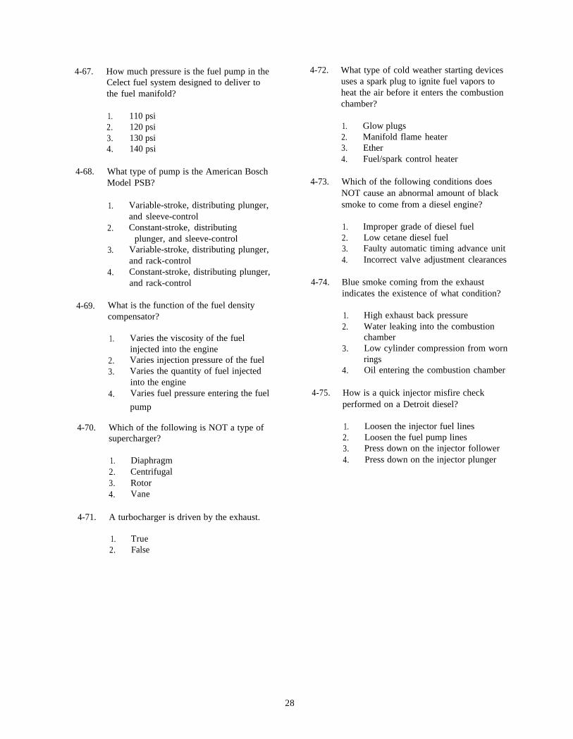
4-67. How much pressure is the fuel pump in theCelect fuel system designed to deliver tothe fuel manifold?
1. 110 psi2. 120 psi3. 130 psi4. 140 psi
4-68. What type of pump is the American BoschModel PSB?
1. Variable-stroke, distributing plunger,and sleeve-control
2. Constant-stroke, distributingplunger, and sleeve-control
3. Variable-stroke, distributing plunger,and rack-control
4. Constant-stroke, distributing plunger,and rack-control
4-69. What is the function of the fuel densitycompensator?
1. Varies the viscosity of the fuelinjected into the engine
2. Varies injection pressure of the fuel3. Varies the quantity of fuel injected
into the engine4. Varies fuel pressure entering the fuel
pump
4-70. Which of the following is NOT a type ofsupercharger?
1. Diaphragm2. Centrifugal3. Rotor4. Vane
4-72. What type of cold weather starting devicesuses a spark plug to ignite fuel vapors toheat the air before it enters the combustionchamber?
1. Glow plugs2. Manifold flame heater3. Ether4. Fuel/spark control heater
4-73. Which of the following conditions doesNOT cause an abnormal amount of blacksmoke to come from a diesel engine?
1. Improper grade of diesel fuel2. Low cetane diesel fuel3. Faulty automatic timing advance unit4. Incorrect valve adjustment clearances
4-74. Blue smoke coming from the exhaustindicates the existence of what condition?
1. High exhaust back pressure2. Water leaking into the combustion
chamber3. Low cylinder compression from worn
rings4. Oil entering the combustion chamber
4-75. How is a quick injector misfire checkperformed on a Detroit diesel?
1. Loosen the injector fuel lines2. Loosen the fuel pump lines3. Press down on the injector follower4. Press down on the injector plunger
4-71. A turbocharger is driven by the exhaust.
1. True2. False
28
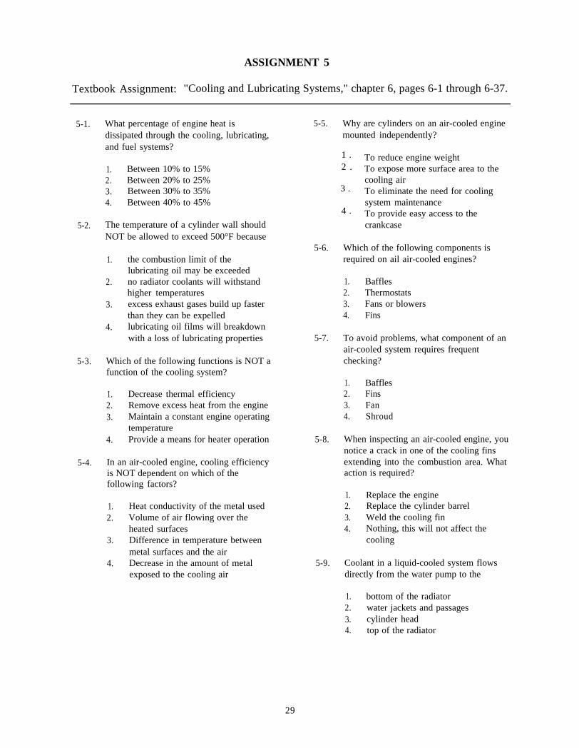
ASSIGNMENT 5
Textbook Assignment: "Cooling and Lubricating Systems," chapter 6, pages 6-1 through 6-37.
5-1. What percentage of engine heat isdissipated through the cooling, lubricating,and fuel systems?
1. Between 10% to 15%2. Between 20% to 25%3. Between 30% to 35%4. Between 40% to 45%
1 .2 .
3 .
4 .
5-2. The temperature of a cylinder wall shouldNOT be allowed to exceed 500°F because
1. the combustion limit of thelubricating oil may be exceeded
2. no radiator coolants will withstandhigher temperatures
3. excess exhaust gases build up fasterthan they can be expelled
4. lubricating oil films will breakdownwith a loss of lubricating properties
5-3. Which of the following functions is NOT afunction of the cooling system?
1.2.3.
4.
Decrease thermal efficiencyRemove excess heat from the engineMaintain a constant engine operatingtemperatureProvide a means for heater operation
5-4. In an air-cooled engine, cooling efficiencyis NOT dependent on which of thefollowing factors?
1. Heat conductivity of the metal used2. Volume of air flowing over the
heated surfaces3. Difference in temperature between
metal surfaces and the air4. Decrease in the amount of metal
exposed to the cooling air
5-5. Why are cylinders on an air-cooled enginemounted independently?
To reduce engine weightTo expose more surface area to thecooling airTo eliminate the need for coolingsystem maintenanceTo provide easy access to thecrankcase
5-6. Which of the following components isrequired on ail air-cooled engines?
1. Baffles2. Thermostats3. Fans or blowers4. Fins
5-7. To avoid problems, what component of anair-cooled system requires frequentchecking?
1. Baffles2. Fins3. Fan4. Shroud
5-8. When inspecting an air-cooled engine, younotice a crack in one of the cooling finsextending into the combustion area. Whataction is required?
1. Replace the engine2. Replace the cylinder barrel3. Weld the cooling fin4. Nothing, this will not affect the
cooling
5-9. Coolant in a liquid-cooled system flowsdirectly from the water pump to the
1. bottom of the radiator2. water jackets and passages3. cylinder head4. top of the radiator
29
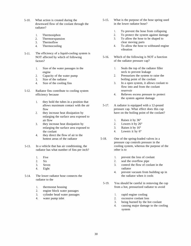
5-10. What action is created during thedownward flow of the coolant through theradiator?
5-15. What is the purpose of the hose spring usedin the lower radiator hose?
1. Thermosiphon2. Thermoexpansion3. Thermoflow4. Thermocooling
1. To prevent the hose from collapsing2. To protect the system against damage3. To allow the hose to be shaped to
clear moving parts4. To allow the hose to withstand engine
vibration5-11. The efficiency of a liquid-cooling system is
NOT affected by which of followingfactors?
5-16. Which of the following is NOT a functionof the radiator pressure cap?
1. Size of the water passages in theengine
2. Capacity of the water pump3. Size of the radiator4. Size of the cooling fins
1. Seals the top of the radiator fillerneck to prevent leakage
2. Pressurizes the system to raise theboiling point of the coolant
5-12. Radiator fins contribute to cooling systemefficiency because
3. In a open system, it allows coolant toflow into and from the coolantreservoir
4. Relieves excess pressure to protectthe system against damage
1. they hold the tubes in a position thatallows maximum contact with the airflow
2. they increase heat dissipation byenlarging the surface area exposed toair flow
3. they increase heat dissipation byenlarging the surface area exposed tothe coolant
4. they direct the flow of air to thehottest areas of the radiator
5-17. A radiator is equipped with a 12-poundpressure cap. What effect does this caphave on the boiling point of the coolant?
1. Raises it by 36°2. Lowers it by 26°3. Raises it by 16°4. Lowers it by 6°
5-18.
5-13. In a vehicle that has air conditioning, theradiator has what number of fins per inch?
One of the spring-loaded valves in apressure cap controls pressure in thecooling system, whereas the purpose of theother is to
1. Five 1. prevent the loss of coolant2. Six 2. seal the overflow pipe3. Seven 3. control the flow of coolant in the4. Eight radiator
5-14. The lower radiator hose connects theradiator to the
4. prevent vacuum from building up inthe radiator when it cools
5-19.1. thermostat housing2. engine block water passages3. cylinder head water passages4. water pump inlet
You should be careful in removing the capfrom a hot, pressurized radiator to avoid
1. rapid engine cooling2. excessive coolant loss3. being burned by the hot coolant4. causing major damage to the cooling
system
30

5-20. What part of the water pump provides amounting place for the fan and belt?
1. Hub2. Housing3. Shaft4. Impeller
5-21. When the gasket is replaced on a waterpump and gasket paper of the properthickness is not available, which of thefollowing materials may be used?
1. Cork2. RTV sealer3. Asbestos4. Rubber
5-22. A bent fan blade will NOT cause which ofthe following conditions?
1. Worn fan belt2. Vibration3. Excessive wear of the water pump
shaft4. Noise
5-23. When an electric fan is used, the fan switchcloses to operate the fan when coolanttemperature reaches approximately whattemperature?
1. 170°F2. 190’F3. 210°F4. 230°F
5-24. Some liquid-cooling systems use a shroudin conjunction with the fan to
1. reduce fan speed at high enginespeeds
2. direct air from the fan to enginesurfaces
3. increase the amount of air drawn bythe fan through the radiator
4. improve the flow of air through theradiator at high speeds
5-25. The water jackets of an engine consists ofonly those passages within the cylinderblock.
1. True2. False
5-26. A coolant distribution tube is used incooling systems of an L-head engine inorder to
1. disperse hot coolant that enters thetop tank of the radiator
2. distribute the coolant equally betweenthe cylinder block and the cylinderhead
3. direct the coolant to the cylinder head
only4. direct the coolant to the hottest parts
of the cylinders
5-27. A ferrule type coolant director is used inthe cooling system of I-head engines. Thedirector directs a jet of coolant towards the
1. exhaust valve guides2. exhaust valve seats3. exhaust ports4. exhaust manifold heat valve
5-28. What type of thermostat is used in amodem pressurized cooling system’?
1. Pellet2. Bypass3. Bellows4. Butterfly
5-29. A thermostat rated at 190°F will fully openat what temperature‘?
1. 190°F2. 200°F3. 210°F4. 220°F
31
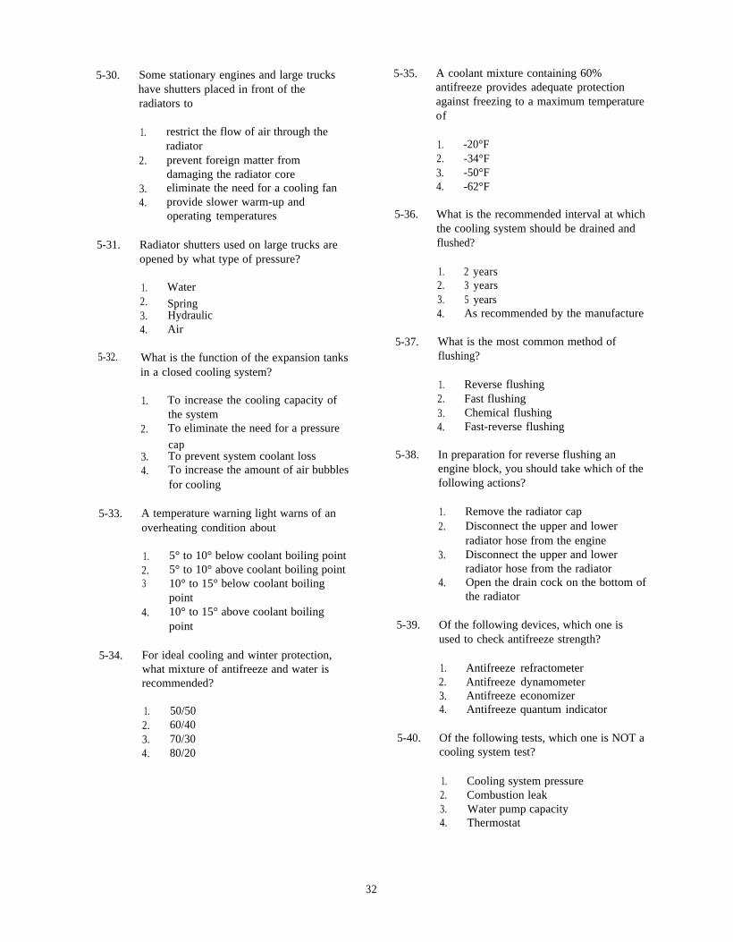
5-30. Some stationary engines and large truckshave shutters placed in front of theradiators to
1. restrict the flow of air through theradiator
2. prevent foreign matter fromdamaging the radiator core
3. eliminate the need for a cooling fan4. provide slower warm-up and
operating temperatures
5-31. Radiator shutters used on large trucks areopened by what type of pressure?
1. Water2. Spring3. Hydraulic4. Air
5-32. What is the function of the expansion tanksin a closed cooling system?
1. To increase the cooling capacity ofthe system
2. To eliminate the need for a pressure
cap3. To prevent system coolant loss4. To increase the amount of air bubbles
for cooling
5-33. A temperature warning light warns of anoverheating condition about
1. 5° to 10° below coolant boiling point2. 5° to 10° above coolant boiling point3 10° to 15° below coolant boiling
point4. 10° to 15° above coolant boiling
point
5-34. For ideal cooling and winter protection,what mixture of antifreeze and water isrecommended?
1. 50/502. 60/403. 70/304. 80/20
5-35. A coolant mixture containing 60%antifreeze provides adequate protectionagainst freezing to a maximum temperatureof
1. -20°F2. -34°F3. -50°F4. -62°F
5-36. What is the recommended interval at whichthe cooling system should be drained andflushed?
1. 2 years2. 3 years3. 5 years4. As recommended by the manufacture
5-37. What is the most common method offlushing?
1. Reverse flushing2. Fast flushing3. Chemical flushing4. Fast-reverse flushing
5-38. In preparation for reverse flushing anengine block, you should take which of thefollowing actions?
1. Remove the radiator cap2. Disconnect the upper and lower
radiator hose from the engine3. Disconnect the upper and lower
radiator hose from the radiator4. Open the drain cock on the bottom of
the radiator
5-39. Of the following devices, which one isused to check antifreeze strength?
1. Antifreeze refractometer2. Antifreeze dynamometer3. Antifreeze economizer4. Antifreeze quantum indicator
5-40. Of the following tests, which one is NOT acooling system test?
1. Cooling system pressure2. Combustion leak3. Water pump capacity4. Thermostat
32
5-41. When a pressure tester is being used to testa radiator cap, what is the minimum lengthof time that the pressure should be held toindicate that the cap is operational?
1. 1 minute2. 2 minutes3. 3 minutes4. 4 minutes
5-42. A combustion leak test should beperformed on the cooling system whenthere is an indication of a blown headgasket.
1. True2. False
5-43. When a combustion leak is detected in thecooling system, the fluid in the block testwill change color from blue to
5-44.
1. green2. orange3. yellow4. purple
You are checking the cooling system andfind a thermostat that fails to operatecorrectly. What should you do with thethermostat?
1. Repair it2. Replace it3. Adjust it4. Clean it
5-45. A 180°F thermostat should be openedcompletely at 180°F.
1. True2. False
5-46. When a thermostatic fan clutch is checkedfor proper operation, the fan should engagewhen cold and slip as the engine warms upthe clutch.
1. True2. False
5-47. When an electric fan is checked for properoperation, what should the resistancereading be when the engine is cold?
5-48.
1. Zero2. Ten3. Twenty4. Infinite
A water pump fails to circulate an adequatevolume of coolant. What is the mostprobable cause of this malfunction?
1. Eroded impeller blades2. A loose fan belt3. Worn pump housing4. Faulty water pump bearings
5-49. A radiator hose is suspected of being faultybut does not feel mushy. The hose must beremoved for inspection if it is
1. preformed2. molded3. spring stiffened4. tension hardened
5-50. Correct fan belt tension can be determinedby measuring the
1. distance between the belt pulleys2. width of the belt3. deflection of the belt between pulleys4. distance between pulleys and
subtracting the width of the belt
5-51. In most applications, you can remove thefan belt after loosening which of thefollowing bolts?
1. Air conditioner mounting2. Power steering mounting3. Fan belt tensioner4. Alternator mounting
33

5-52. After shutting down an engine that has runfor some time, you can check the radiatorto see if it is partially clogged by
1. taking the temperature of the coolantin the lower radiator outlet
2. taking the temperature of the coolantin the upper radiator tank
3. feeling the upper and lower radiatorhoses with your hand
4. feeling the top and bottom of theradiator core with your hand
5-53. Why is a very small leak easier to detect ina cooling system containing an antifreezesolution?
1. Antifreeze leaves a residue2. More antifreeze leaks through than
water3. Antifreeze does not evaporate as fast
as water4. Antifreeze is colored
5-54. Which of the following is NOT a functionof the engine lubrication system?
1. Reduces friction between movingparts
2. Transfers heat3. Cleans the inside of the engine by
removing contaminants4. Assures maximum wear on moving
parts
5-55. Oil service ratings are determined by whatagency?
1. The Society of Automotive Engineers2. The Society of Petroleum Engineers3. The American Petroleum Institute4. The American Automotive Institute
5-56. What oil service rating meets warrantyrequirements for modem gasoline engines?
5-57. Which of the following is an operatingprinciple of the rotary oil pump?
1. The inner rotor is centrally located inthe outer rotor
2. The inner rotor causes the outer rotorto spin
3. The outer rotor causes the inner rotorto spin
4. A small pocket is formed on the inletside of the pump
5-58. Which of the following actions is anoperating principle of a gear type oilpump?
1. Both gears are independently drivenby shafts
2. Both gears turn in the same direction3. Pumping action forces oil to pass
between the gear teeth4. The pump is driven by the crankshaft
or distributor
5-59. Why is a relief valve placed in thelubrication system of an engine?
1. To regulate pressure delivered by theoil pump
2. To prevent damaging the internalparts of the oil pump
3. To provide an adequate supply of oilto the suction side of the oil pump
4. To prevent overlubrication of theengine bearings
5-60. In an engine lubrication system, where isthe oil strainer located?
1. In the oil return line to the crankcase2. At the inlet of the oil pump pickup
tube3. In the discharge line from the oil
pump4. At the inlet side of the oil galleries
1. SG2. S F3. SE4. SD
34
5-61. Oil strainers sometimes contain a safety 5-65. In a mechanical type oil pressure gauge,valve for the purpose of the oil line is tapped at what location?
1. allowing oil to bypass a cloggedscreen
2. limiting the amount of oil enteringthe oil pump
3. controlling pump discharge pressure4. controlling the oil level in the oil pan
5-62. Dirt, water, and sludge can NOT passthrough an oil strainer with the oil becauseof which of the following reasons?
1. All oil is collected from the surface ofthe oil in the oil pan
2. The mesh of the screen will allowonly the lubricating oil to pass
3. The strainers are located above thebottom of the oil pan
4. The strainers are designed to allow oilpumps to pick up oil based on theirviscosity
5-63. Of the following factors, which is anadvantage of using a full flow oil filter in alubricating system?
1. All oil is circulated through the filterbefore it reaches the engine
2. The filter does not need to bechanged as often as other filters
3. The filter never permits anyunfiltered oil to reach the movingparts of the engine
4. The filter diverts a small amount ofoil and returns it to the oil pan
5-64. The sending unit for an oil pressurewarning light is calibrated to come onwhen oil pressure drops below what level?
1. 10 psi2. 15 psi3. 20 psi4. 25 psi
1. At the base of the oil filter2. At the oil gallery leading from the oil
pump3. At the oil gallery leading from the
side of the engine4. At the oil filter housing unit
5-66. In an overhead valve engine using acombination splash and force-feed system,the upper valve train is lubricated by
1. the splash method2. a combination of both the splash and
force-feed methods3. pressure from the oil pump4. dippers on the connecting rods
5-67. An operator reports that a vehicle is using alot of oil; however, there is no sign ofexternal leakage. What color smoke is asign of internal oil leakage?
1. Gray2. Black3. White4. Blue
5-68. Which of the following conditions is NOTa cause of low oil pressure?
1. Worn main bearings2. Worn oil pump3. Restricted oil gallery4. Weak or broken pressure relief valve
spring
5-69. Which of the following conditions isindicated by a high oil pressure reading?
1. Worn engine bearings2. Overheated engine3. Blocked oil passage4. Cracked oil pickup tube
35
5-70. In changing engine oil, you should drainthe oil from the vehicle
1. when the engine is warm2. while the engine is cold3. anytime4. whenever the vehicle is deadlined
5-71. When replacing a spin-on filter, you shouldturn the filter how far after contact is madewith the base?
5-72. Before installing a new oil pump, youshould fill the pumping chamber with oil
1. to eliminate air pockets that couldrestrict oil flow
2. to reduce the chances that the pumpshaft will bind
3. to prevent rotor damage when theengine is started
4. to ensure proper operation when theengine is started
1. One-fourth him2. One-third turn3. One-half turn4. Full turn
36