Embed Size (px)
Citation preview
Catalyst 2900 Series XL and Catalyst 3500 Ser78-6511-08
C H A P T E R 8
the
rt a seturesmand IOS
the
Configuring VLANs
This chapter provides these topics about configuring virtual LANs (VLANs):
• Overview, page 8-1
• Management VLANs, page 8-3
• Assigning VLAN Port Membership Modes, page 8-5
• Assigning Static-Access Ports to a VLAN, page 8-7
• Overlapping VLANs and Multi-VLAN Ports, page 8-7
• Using VTP, page 8-9
• VLANs in the VTP Database, page 8-20
• How VLAN Trunks Work, page 8-26
• Configuring 802.1p Class of Service, page 8-31
• Load Sharing Using STP, page 8-32
• How the VMPS Works, page 8-36
Note Certain port features can conflict with one another. Review the“Avoiding Configuration Conflicts”section on page 9-7 before you change the port settings.
For information about configuring these settings from Cluster Management Suite (CMS), refer toonline help.
This switch software release is based on Cisco IOS Release 12.0. It has been enhanced to suppoof features for the Catalyst 2900 XL and Catalyst 3500 XL switches. This chapter provides procedfor using only the commands that have been created or changed for these switches. The switch comreference provides complete descriptions of these commands. This guide does not provide CiscoRelease 12.0 commands and information already documented in the Cisco IOS Release 12.0documentation on Cisco.com.
For information about configuring these settings from Cluster Management Suite (CMS), refer toonline help.
8-1ies XL Software Configuration Guide
Chapter 8 Configuring VLANsOverview
orAN,LAN.
o the
nte
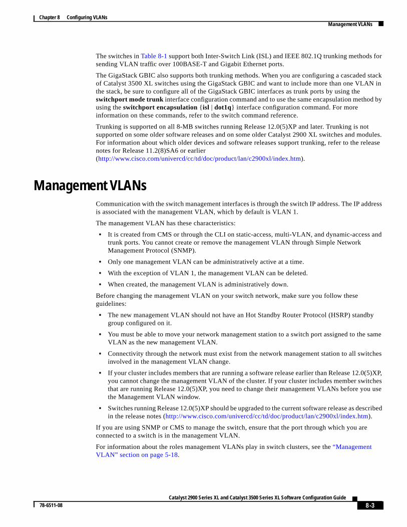
OverviewA virtual LAN (VLAN) is a switched network that is logically segmented by function, project team,application, without regard to the physical locations of the users. Any switch port can belong to a VLand unicast, broadcast, and multicast packets are forwarded and flooded only to stations in the VEach VLAN is considered a logical network, and packets destined for stations that do not belong tVLAN must be forwarded through a router or bridge as shown inFigure 8-1. VLANs are identified witha number of 1 to 1001.
Because a VLAN is considered a separate logical network, it contains its own bridge ManagemeInformation Base (MIB) information and can support its own implementation of the Spanning TreProtocol (STP). For information about managing VLAN STP instances, see the“Supported STPInstances” section on page 6-33.
Table 8-1 lists the number of supported VLANs and STP instances on the switches.
Figure 8-1 VLANs as Logically Defined Networks
Table 8-1 Maximum Number of Supported VLANs
SwitchMaximum Numberof VLANs
Maximum Numberof STP Instances
TrunkingSupported?
Catalyst 2912 XL, Catalyst 2924 XL, andCatalyst 2924C XL switches
64 64 Yes
Catalyst 2900 LRE XL switches 250 64 Yes
Catalyst 2912M and Catalyst 2924Mmodular switches
250 64 Yes
Catalyst 3500 XL switches 250 64 Yes
Floor 1
Floor 2
EngineeringVLAN
Cisco router
Fast Ethernet
Catalyst 2900 series XL
Catalyst 3500 series XL
Floor 3
MarketingVLAN
AccountingVLAN
1593
3
Catalyst 2900 series XL
8-2Catalyst 2900 Series XL and Catalyst 3500 Series XL Software Configuration Guide
78-6511-08
Chapter 8 Configuring VLANsManagement VLANs
r
stackN in
d by
tdules.lease
dress
and
by
same
hes
(5)XP,chesou use
scribed
The switches inTable 8-1support both Inter-Switch Link (ISL) and IEEE 802.1Q trunking methods fosending VLAN traffic over 100BASE-T and Gigabit Ethernet ports.
The GigaStack GBIC also supports both trunking methods. When you are configuring a cascadedof Catalyst 3500 XL switches using the GigaStack GBIC and want to include more than one VLAthe stack, be sure to configure all of the GigaStack GBIC interfaces as trunk ports by using theswitchport mode trunk interface configuration command and to use the same encapsulation methousing theswitchport encapsulation { isl | dot1q} interface configuration command. For moreinformation on these commands, refer to the switch command reference.
Trunking is supported on all 8-MB switches running Release 12.0(5)XP and later. Trunking is nosupported on some older software releases and on some older Catalyst 2900 XL switches and moFor information about which older devices and software releases support trunking, refer to the renotes for Release 11.2(8)SA6 or earlier(http://www.cisco.com/univercd/cc/td/doc/product/lan/c2900xl/index.htm).
Management VLANsCommunication with the switch management interfaces is through the switch IP address. The IP adis associated with the management VLAN, which by default is VLAN 1.
The management VLAN has these characteristics:
• It is created from CMS or through the CLI on static-access, multi-VLAN, and dynamic-accesstrunk ports. You cannot create or remove the management VLAN through Simple NetworkManagement Protocol (SNMP).
• Only one management VLAN can be administratively active at a time.
• With the exception of VLAN 1, the management VLAN can be deleted.
• When created, the management VLAN is administratively down.
Before changing the management VLAN on your switch network, make sure you follow theseguidelines:
• The new management VLAN should not have an Hot Standby Router Protocol (HSRP) standgroup configured on it.
• You must be able to move your network management station to a switch port assigned to theVLAN as the new management VLAN.
• Connectivity through the network must exist from the network management station to all switcinvolved in the management VLAN change.
• If your cluster includes members that are running a software release earlier than Release 12.0you cannot change the management VLAN of the cluster. If your cluster includes member switthat are running Release 12.0(5)XP, you need to change their management VLANs before ythe Management VLAN window.
• Switches running Release 12.0(5)XP should be upgraded to the current software release as dein the release notes (http://www.cisco.com/univercd/cc/td/doc/product/lan/c2900xl/index.htm).
If you are using SNMP or CMS to manage the switch, ensure that the port through which you areconnected to a switch is in the management VLAN.
For information about the roles management VLANs play in switch clusters, see the“ManagementVLAN” section on page 5-18.
8-3Catalyst 2900 Series XL and Catalyst 3500 Series XL Software Configuration Guide
78-6511-08
Chapter 8 Configuring VLANsManagement VLANs
r thantge thege ofere
luster thethebe
en no
e of
ough
a
Changing the Management VLAN for a New SwitchIf you add a new switch to an existing cluster and the cluster is using a management VLAN othethe default VLAN 1, the command switch automatically senses that the new switch has a differenmanagement VLAN and has not been configured. The command switch issues commands to chanmanagement VLAN on the new switch to match the one in use by the cluster. This automatic chanthe VLAN only occurs for new, out-of-box switches that do not have a config.text file and for which thhave been no changes to the running configuration.
Before a new switch can be added to a cluster, it must be connected to a port that belongs to the cmanagement VLAN. If the cluster is configured with a management VLAN other than the default,command switch changes the management VLAN for new switches when they are connected to cluster. In this way, the new switch can exchange CDP messages with the command switch and proposed as a cluster candidate.
Note For the command switch to change the management VLAN on a new switch, there must have bechanges to the new switch configuration, and there must be no config.text file.
Because the switch is new and unconfigured, its management VLAN is changed to the clustermanagement VLAN when it is first added to the cluster. All ports that have an active link at the timthis change become members of the new management VLAN.
For information about the roles management VLANs play in switch clusters, see the“ManagementVLAN” section on page 5-18.
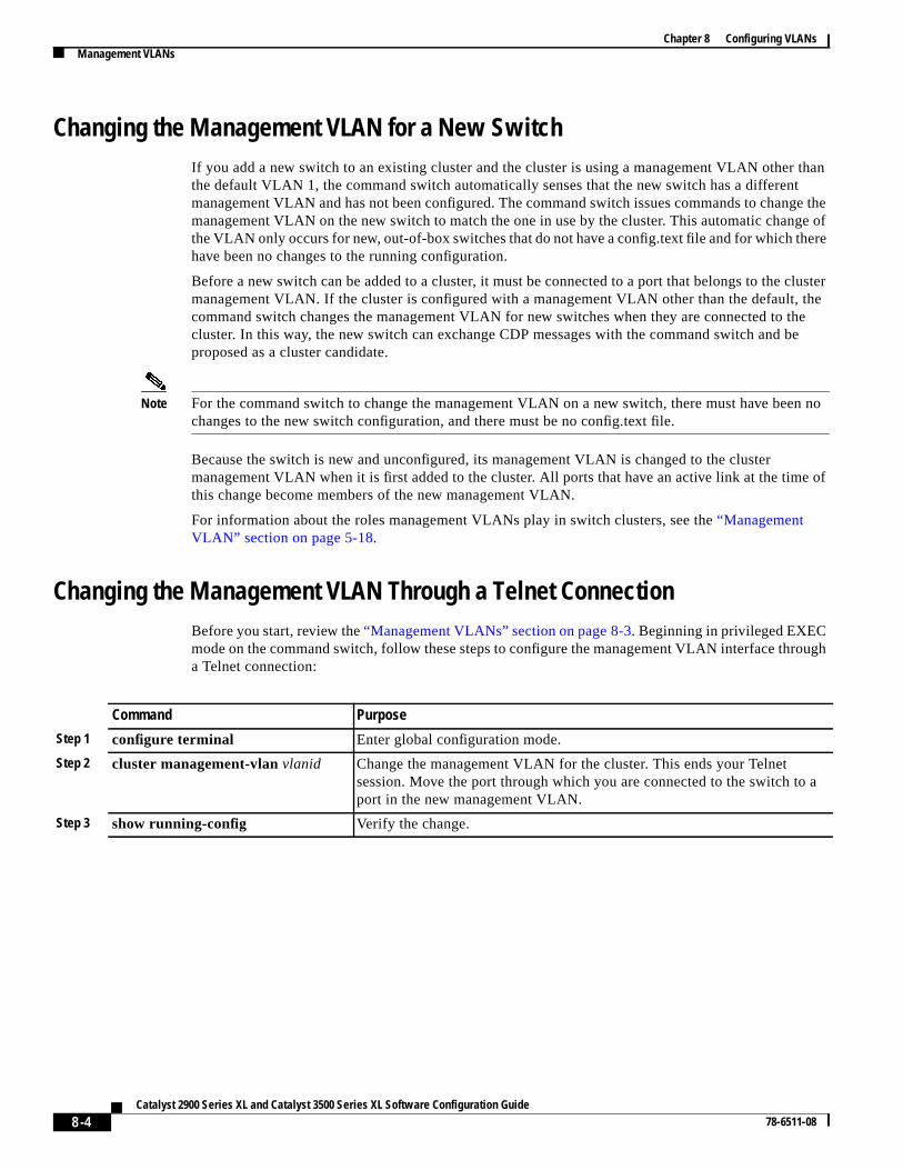
Changing the Management VLAN Through a Telnet ConnectionBefore you start, review the“Management VLANs” section on page 8-3. Beginning in privileged EXECmode on the command switch, follow these steps to configure the management VLAN interface thra Telnet connection:
Command Purpose
Step 1 configure terminal Enter global configuration mode.
Step 2 cluster management-vlanvlanid Change the management VLAN for the cluster. This ends your Telnetsession. Move the port through which you are connected to the switch toport in the new management VLAN.
Step 3 show running-config Verify the change.
8-4Catalyst 2900 Series XL and Catalyst 3500 Series XL Software Configuration Guide
78-6511-08
Chapter 8 Configuring VLANsAssigning VLAN Port Membership Modes
d of
e port
h.
y
,
n
e
shipL or
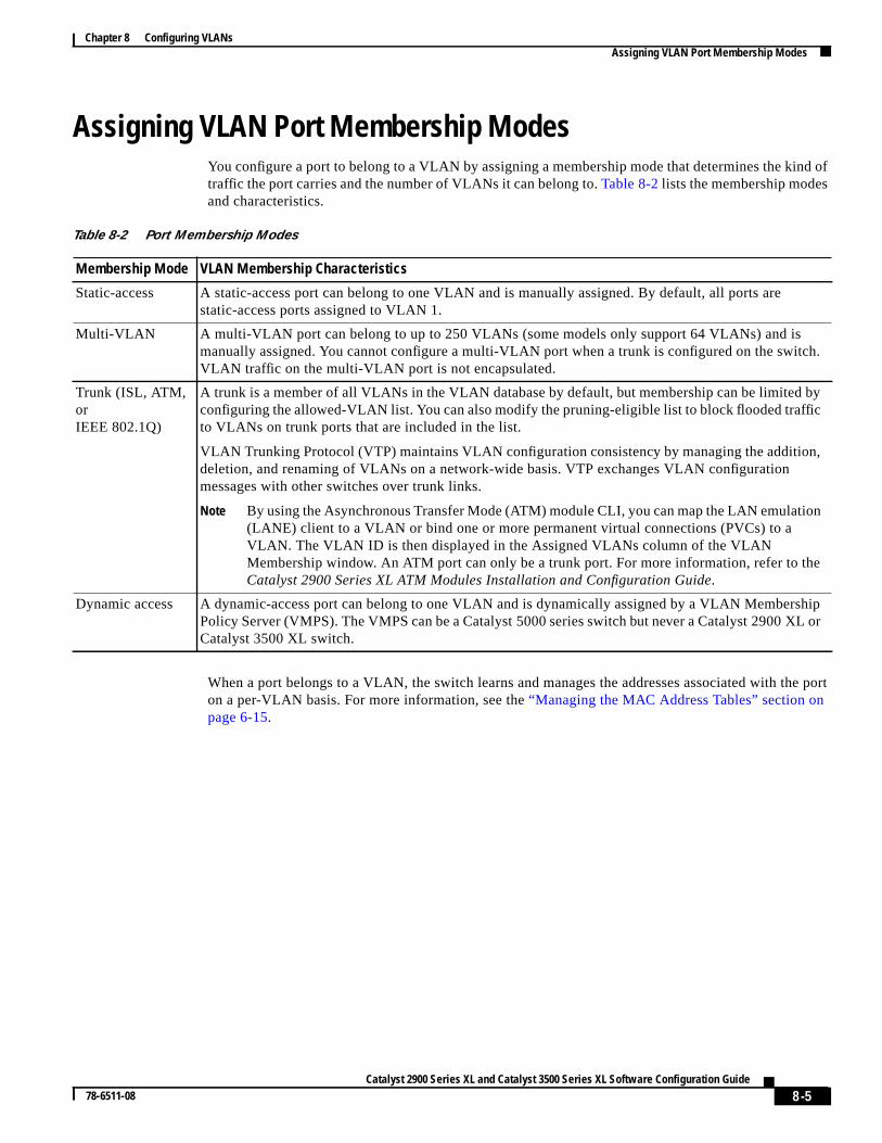
Assigning VLAN Port Membership ModesYou configure a port to belong to a VLAN by assigning a membership mode that determines the kintraffic the port carries and the number of VLANs it can belong to.Table 8-2lists the membership modesand characteristics.
When a port belongs to a VLAN, the switch learns and manages the addresses associated with thon a per-VLAN basis. For more information, see the“Managing the MAC Address Tables” section onpage 6-15.
Table 8-2 Port Membership Modes
Membership Mode VLAN Membership Characteristics
Static-access A static-access port can belong to one VLAN and is manually assigned. By default, all ports arestatic-access ports assigned to VLAN 1.
Multi-VLAN A multi-VLAN port can belong to up to 250 VLANs (some models only support 64 VLANs) and ismanually assigned. You cannot configure a multi-VLAN port when a trunk is configured on the switcVLAN traffic on the multi-VLAN port is not encapsulated.
Trunk (ISL, ATM,orIEEE 802.1Q)
A trunk is a member of all VLANs in the VLAN database by default, but membership can be limited bconfiguring the allowed-VLAN list. You can also modify the pruning-eligible list to block flooded trafficto VLANs on trunk ports that are included in the list.
VLAN Trunking Protocol (VTP) maintains VLAN configuration consistency by managing the additiondeletion, and renaming of VLANs on a network-wide basis. VTP exchanges VLAN configurationmessages with other switches over trunk links.
Note By using the Asynchronous Transfer Mode (ATM) module CLI, you can map the LAN emulatio(LANE) client to a VLAN or bind one or more permanent virtual connections (PVCs) to aVLAN. The VLAN ID is then displayed in the Assigned VLANs column of the VLANMembership window. An ATM port can only be a trunk port. For more information, refer to thCatalyst 2900 Series XL ATM Modules Installation and Configuration Guide.
Dynamic access A dynamic-access port can belong to one VLAN and is dynamically assigned by a VLAN MemberPolicy Server (VMPS). The VMPS can be a Catalyst 5000 series switch but never a Catalyst 2900 XCatalyst 3500 XL switch.
8-5Catalyst 2900 Series XL and Catalyst 3500 Series XL Software Configuration Guide
78-6511-08
Chapter 8 Configuring VLANsAssigning VLAN Port Membership Modes
d
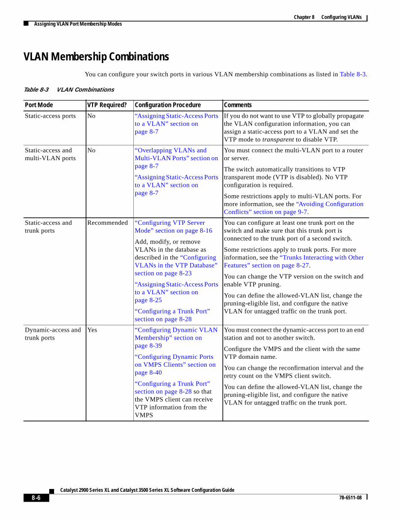
VLAN Membership CombinationsYou can configure your switch ports in various VLAN membership combinations as listed inTable 8-3.
Table 8-3 VLAN Combinations
Port Mode VTP Required? Configuration Procedure Comments
Static-access ports No “Assigning Static-Access Portsto a VLAN” section onpage 8-7
If you do not want to use VTP to globally propagatethe VLAN configuration information, you canassign a static-access port to a VLAN and set theVTP mode totransparent to disable VTP.
Static-access andmulti-VLAN ports
No “Overlapping VLANs andMulti-VLAN Ports” section onpage 8-7
“Assigning Static-Access Portsto a VLAN” section onpage 8-7
You must connect the multi-VLAN port to a routeror server.
The switch automatically transitions to VTPtransparent mode (VTP is disabled). No VTPconfiguration is required.
Some restrictions apply to multi-VLAN ports. Formore information, see the“Avoiding ConfigurationConflicts” section on page 9-7.
Static-access andtrunk ports
Recommended “Configuring VTP ServerMode” section on page 8-16
Add, modify, or removeVLANs in the database asdescribed in the“ConfiguringVLANs in the VTP Database”section on page 8-23
“Assigning Static-Access Portsto a VLAN” section onpage 8-25
“Configuring a Trunk Port”section on page 8-28
You can configure at least one trunk port on theswitch and make sure that this trunk port isconnected to the trunk port of a second switch.
Some restrictions apply to trunk ports. For moreinformation, see the“Trunks Interacting with OtherFeatures” section on page 8-27.
You can change the VTP version on the switch andenable VTP pruning.
You can define the allowed-VLAN list, change thepruning-eligible list, and configure the nativeVLAN for untagged traffic on the trunk port.
Dynamic-access andtrunk ports
Yes “Configuring Dynamic VLANMembership” section onpage 8-39
“Configuring Dynamic Portson VMPS Clients” section onpage 8-40
“Configuring a Trunk Port”section on page 8-28 so thatthe VMPS client can receiveVTP information from theVMPS
You must connect the dynamic-access port to an enstation and not to another switch.
Configure the VMPS and the client with the sameVTP domain name.
You can change the reconfirmation interval and theretry count on the VMPS client switch.
You can define the allowed-VLAN list, change thepruning-eligible list, and configure the nativeVLAN for untagged traffic on the trunk port.
8-6Catalyst 2900 Series XL and Catalyst 3500 Series XL Software Configuration Guide
78-6511-08
Chapter 8 Configuring VLANsAssigning Static-Access Ports to a VLAN
bles
hip:
enichted by
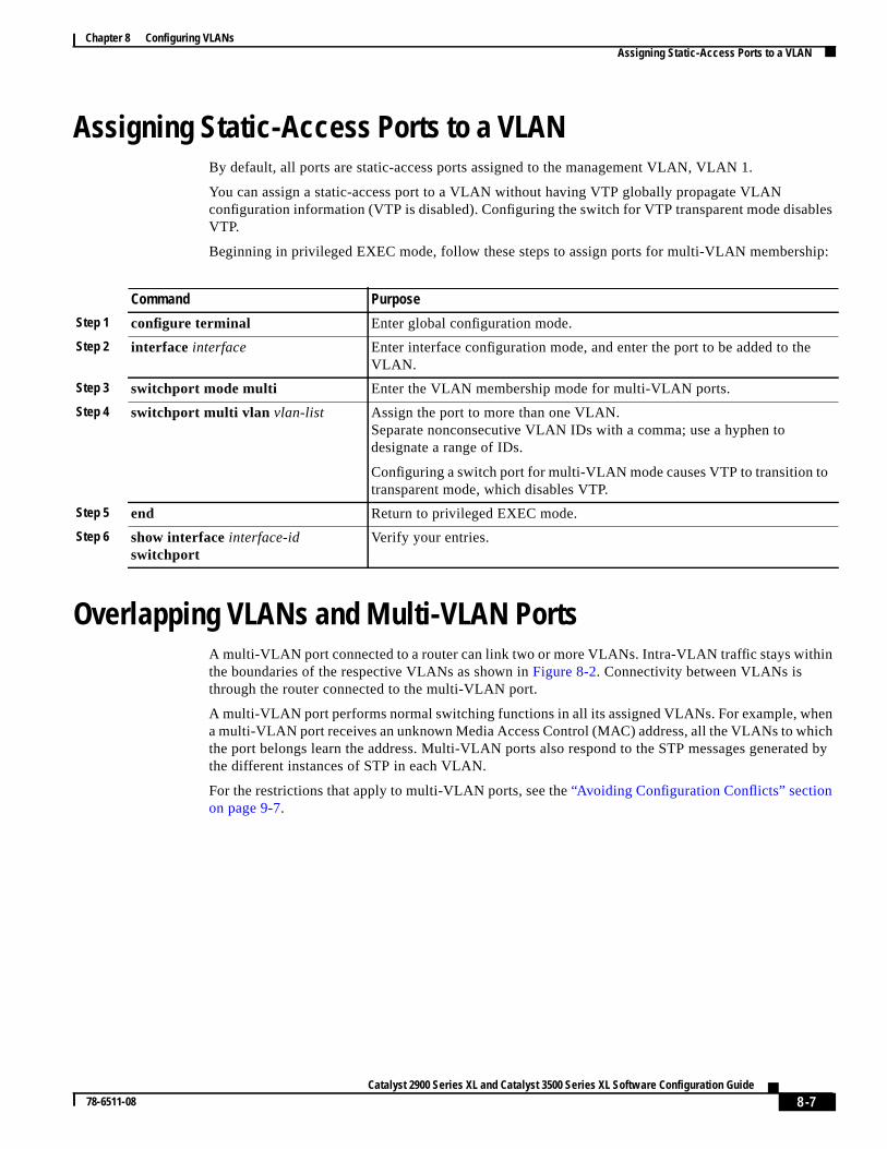
Assigning Static-Access Ports to a VLANBy default, all ports are static-access ports assigned to the management VLAN, VLAN 1.
You can assign a static-access port to a VLAN without having VTP globally propagate VLANconfiguration information (VTP is disabled). Configuring the switch for VTP transparent mode disaVTP.
Beginning in privileged EXEC mode, follow these steps to assign ports for multi-VLAN members
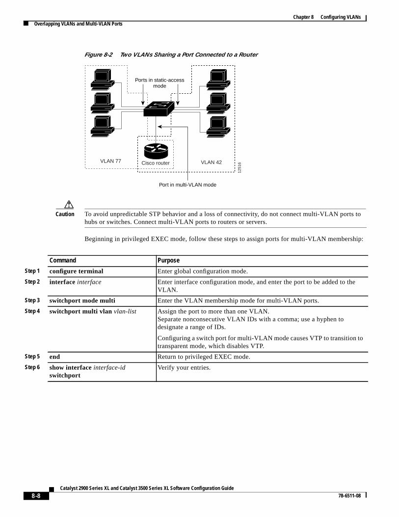
Overlapping VLANs and Multi-VLAN PortsA multi-VLAN port connected to a router can link two or more VLANs. Intra-VLAN traffic stays withinthe boundaries of the respective VLANs as shown inFigure 8-2. Connectivity between VLANs isthrough the router connected to the multi-VLAN port.
A multi-VLAN port performs normal switching functions in all its assigned VLANs. For example, wha multi-VLAN port receives an unknown Media Access Control (MAC) address, all the VLANs to whthe port belongs learn the address. Multi-VLAN ports also respond to the STP messages generathe different instances of STP in each VLAN.
For the restrictions that apply to multi-VLAN ports, see the“Avoiding Configuration Conflicts” sectionon page 9-7.
Command Purpose
Step 1 configure terminal Enter global configuration mode.
Step 2 interface interface Enter interface configuration mode, and enter the port to be added to theVLAN.
Step 3 switchport mode multi Enter the VLAN membership mode for multi-VLAN ports.
Step 4 switchport multi vlan vlan-list Assign the port to more than one VLAN.Separate nonconsecutive VLAN IDs with a comma; use a hyphen todesignate a range of IDs.
Configuring a switch port for multi-VLAN mode causes VTP to transition totransparent mode, which disables VTP.
Step 5 end Return to privileged EXEC mode.
Step 6 show interfaceinterface-idswitchport
Verify your entries.
8-7Catalyst 2900 Series XL and Catalyst 3500 Series XL Software Configuration Guide
78-6511-08
Chapter 8 Configuring VLANsOverlapping VLANs and Multi-VLAN Ports
to
ip:
Figure 8-2 Two VLANs Sharing a Port Connected to a Router
Caution To avoid unpredictable STP behavior and a loss of connectivity, do not connect multi-VLAN portshubs or switches. Connect multi-VLAN ports to routers or servers.
Beginning in privileged EXEC mode, follow these steps to assign ports for multi-VLAN membersh
VLAN 42
1251
6Cisco routerVLAN 77
Ports in static-accessmode
Port in multi-VLAN mode
Command Purpose
Step 1 configure terminal Enter global configuration mode.
Step 2 interface interface Enter interface configuration mode, and enter the port to be added to theVLAN.
Step 3 switchport mode multi Enter the VLAN membership mode for multi-VLAN ports.
Step 4 switchport multi vlan vlan-list Assign the port to more than one VLAN.Separate nonconsecutive VLAN IDs with a comma; use a hyphen todesignate a range of IDs.
Configuring a switch port for multi-VLAN mode causes VTP to transition totransparent mode, which disables VTP.
Step 5 end Return to privileged EXEC mode.
Step 6 show interfaceinterface-idswitchport
Verify your entries.
8-8Catalyst 2900 Series XL and Catalyst 3500 Series XL Software Configuration Guide
78-6511-08
Chapter 8 Configuring VLANsUsing VTP
theonses,
can
itches
VTP
untille
e or
to all
nges
Using VTPVTP is a Layer 2 messaging protocol that maintains VLAN configuration consistency by managingaddition, deletion, and renaming of VLANs on a network-wide basis. VTP minimizes misconfiguratiand configuration inconsistencies that can cause several problems, such as duplicate VLAN namincorrect VLAN-type specifications, and security violations.
Before you create VLANs, you must decide whether to use VTP in your network. Using VTP, youmake configuration changes centrally on a single switch, such as a Catalyst 2900 XL orCatalyst 3500 XL switch, and have those changes automatically communicated to all the other swin the network. Without VTP, you cannot send information about VLANs to other switches.
The VTP DomainA VTP domain (also called a VLAN management domain) consists of one switch or severalinterconnected switches under the same administrative responsibility. A switch can be in only onedomain. You make global VLAN configuration changes for the domain by using the CLI, ClusterManagement software, or SNMP.
By default, a Catalyst 2900 XL or Catalyst 3500 XL switch is in the no-management-domain stateit receives an advertisement for a domain over a trunk link (a link that carries the traffic of multipVLANs) or until you configure a domain name. The default VTP mode is server mode, but VLANinformation is not propagated over the network until a domain name is specified or learned.
If the switch receives a VTP advertisement over a trunk link, it inherits the domain name andconfiguration revision number. The switch then ignores advertisements with a different domain naman earlier configuration revision number.
When you make a change to the VLAN configuration on a VTP server, the change is propagatedswitches in the VTP domain. VTP advertisements are sent over all trunk connections, includingInter-Switch Link (ISL), IEEE 802.1Q, IEEE 802.10, and ATM LANE.
If you configure a switch for VTP transparent mode, you can create and modify VLANs, but the chaare not sent to other switches in the domain, and they affect only the individual switch.
For domain name and password configuration guidelines, see the“Domain Names” section onpage 8-13.
8-9Catalyst 2900 Series XL and Catalyst 3500 Series XL Software Configuration Guide
78-6511-08
Chapter 8 Configuring VLANsUsing VTP
rt aTP
that
de,
n
ge,
r,ernt
t
VTP Modes and Mode TransitionsYou can configure a supported switch to be in one of the VTP modes listed inTable 8-4.
Two configurations can cause a switch to automatically change its VTP mode:
• When the network is configured with more than the maximum 250 VLANs (some models suppomaximum of 64 VLANs), the switch automatically changes from VTP server or client mode to Vtransparent mode. The switch then operates with the VLAN configuration that preceded the onesent it into transparent mode.
• When a multi-VLAN port is configured on a supported switch in VTP server mode or client mothe switch automatically changes to transparent mode.
The“VTP Configuration Guidelines” section on page 8-13 provides tips and caveats for configuringVTP.
Table 8-4 VTP Modes
VTP Mode Description
VTP server In this mode, you can create, modify, and delete VLANs and specify otherconfiguration parameters (such as VTP version) for the entire VTP domain. VTPservers advertise their VLAN configurations to other switches in the same VTPdomain and synchronize their VLAN configurations with other switches based oadvertisements received over trunk links.
In VTP server mode, VLAN configurations are saved in nonvolatile RAM. VTPserver is the default mode.
VTP client In this mode, a VTP client behaves like a VTP server, but you cannot create, chanor delete VLANs on a VTP client.
In VTP client mode, VLAN configurations are saved in nonvolatile RAM.
VTP transparent In this mode, VTP transparent switches do not participate in VTP. A VTPtransparent switch does not advertise its VLAN configuration and does notsynchronize its VLAN configuration based on received advertisements. Howevetransparent switches do forward VTP advertisements that they receive from othswitches. You can create, modify, and delete VLANs on a switch in VTP transparemode.
In VTP transparent mode, VLAN configurations are saved in nonvolatile RAM, buthey are not advertised to other switches.
8-10Catalyst 2900 Series XL and Catalyst 3500 Series XL Software Configuration Guide
78-6511-08
Chapter 8 Configuring VLANsUsing VTP
porteir VTP
nk porttch.
ngore
tiond in
VTPomains in
d
ion ist on
VTP AdvertisementsEach switch in the VTP domain sends periodic global configuration advertisements from each trunkto a reserved multicast address. Neighboring switches receive these advertisements and update thand VLAN configurations as necessary.
Note Because trunk ports send and receive VTP advertisements, you must ensure that at least one truis configured on the switch and that this trunk port is connected to the trunk port of a second swiOtherwise, the switch cannot receive any VTP advertisements.
VTP advertisements distribute this global domain information in VTP advertisements:
• VTP domain name
• VTP configuration revision number
• Update identity and update timestamp
• MD5 digest
VTP advertisements distribute this VLAN information for each configured VLAN:
• VLAN ID
• VLAN name
• VLAN type
• VLAN state
• Additional VLAN configuration information specific to the VLAN type
VTP Version 2VTP version 2 supports these features not supported in version 1:
• Token Ring support—VTP version 2 supports Token Ring LAN switching and VLANs (Token RiBridge Relay Function [TRBRF] and Token Ring Concentrator Relay Function [TRCRF]). For minformation about Token Ring VLANs, see the“VLANs in the VTP Database” section on page 8-20.
• Unrecognized Type-Length-Value (TLV) support—A VTP server or client propagates configurachanges to its other trunks, even for TLVs it is not able to parse. The unrecognized TLV is savenonvolatile RAM when the switch is operating in VTP server mode.
• Version-Dependent Transparent Mode—In VTP version 1, a VTP transparent switch inspectsmessages for the domain name and version and forwards a message only if the version and dname match. Because only one domain is supported, VTP version 2 forwards VTP messagetransparent mode without checking the version and domain name.
• Consistency Checks—In VTP version 2, VLAN consistency checks (such as VLAN names anvalues) are performed only when you enter new information through the CLI, the ClusterManagement software, or SNMP. Consistency checks are not performed when new informatobtained from a VTP message or when information is read from nonvolatile RAM. If the digesa received VTP message is correct, its information is accepted without consistency checks.
8-11Catalyst 2900 Series XL and Catalyst 3500 Series XL Software Configuration Guide
78-6511-08
Chapter 8 Configuring VLANsUsing VTP
afficicast,hes
. Ifrted
1 islinks
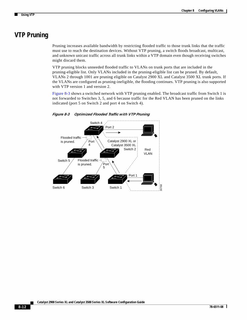
VTP PruningPruning increases available bandwidth by restricting flooded traffic to those trunk links that the trmust use to reach the destination devices. Without VTP pruning, a switch floods broadcast, multand unknown unicast traffic across all trunk links within a VTP domain even though receiving switcmight discard them.
VTP pruning blocks unneeded flooded traffic to VLANs on trunk ports that are included in thepruning-eligible list. Only VLANs included in the pruning-eligible list can be pruned. By default,VLANs 2 through 1001 are pruning eligible on Catalyst 2900 XL and Catalyst 3500 XL trunk portsthe VLANs are configured as pruning-ineligible, the flooding continues. VTP pruning is also suppowith VTP version 1 and version 2.
Figure 8-3shows a switched network with VTP pruning enabled. The broadcast traffic from Switchnot forwarded to Switches 3, 5, and 6 because traffic for the Red VLAN has been pruned on the indicated (port 5 on Switch 2 and port 4 on Switch 4).
Figure 8-3 Optimized Flooded Traffic with VTP Pruning
Switch 4
Switch 5
Switch 3Switch 6 Switch 1
Catalyst 2900 XL orCatalyst 3500 XL
Switch 2
Port 1
Port 2
Red VLAN
3076
8
Port4
Port5
Flooded trafficis pruned.
Flooded trafficis pruned.
8-12Catalyst 2900 Series XL and Catalyst 3500 Series XL Software Configuration Guide
78-6511-08

Chapter 8 Configuring VLANsUsing VTP
themodemain
theake
bersary,LANhat
ion
me.
VTP Configuration Guidelines
Domain Names
When configuring VTP for the first time, you must always assign a domain name. All switches in VTP domain must also be configured with the same domain name. Switches in VTP transparent do not exchange VTP messages with other switches, and you do not need to configure a VTP doname for them.
Caution Do not configure a VTP domain if all switches are operating in VTP client mode. If you configuredomain, it is impossible to make changes to the VLAN configuration of that domain. Therefore, msure you configure at least one switch in the VTP domain for VTP server mode.
VTP Version Numbers
When you add a VTP client, follow this caution and procedure:
Caution Before adding a VTP client to a VTP domain, always verify that its VTP configuration revision numis lower than the configuration revision number of the other switches in the VTP domain. If necesreset the switch configuration revision number to 0. Switches in a VTP domain always use the Vconfiguration of the switch with the highest VTP configuration revision number. If you add a switch thas a revision number higher than the revision number in the VTP domain, it can erase all VLANinformation from the VTP server and VTP domain.
Beginning in user EXEC mode, follow these steps to verify and reset the VTP configuration revisnumber on a switchbefore adding it to a VTP domain:
Command Purpose
Step 1 show vtp status Check the VTP configuration revision number.
If the number is 0, add the switch to the VTP domain.
If the number is greater than 0, follow these steps:
a. Write down the domain name.
b. Write down the configuration revision number.
Continue with the next steps to reset the configuration revision number on theswitch.
Step 2 enable Enter privileged EXEC mode.
Step 3 vlan database Enter VLAN database mode.
Step 4 vtp domain domain-name Change the domain name from the original one displayed in Step 1 to a new na
Step 5 exit The VLAN information on the switch is updated, and the configuration revisionnumber is reset to 0. You return to privileged EXEC mode.
Step 6 show vtp status Verify that the configuration revision number has been reset to 0.
Step 7 vlan database Enter VLAN database mode.
Step 8 vtp domain domain-name Enter the original domain name on the switch.
8-13Catalyst 2900 Series XL and Catalyst 3500 Series XL Software Configuration Guide
78-6511-08
Chapter 8 Configuring VLANsUsing VTP
ngen
hare
the
at isthees the
s the
A3) toPthe
the the
e.
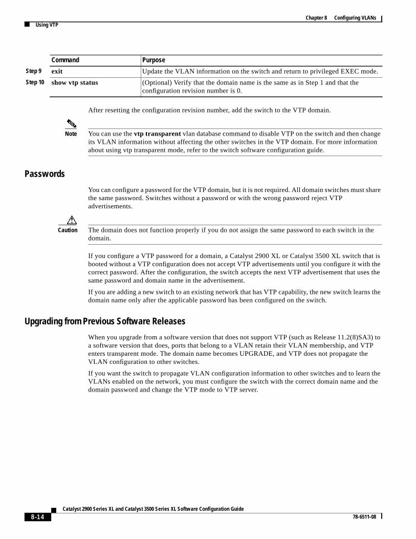
After resetting the configuration revision number, add the switch to the VTP domain.
Note You can use thevtp transparent vlan database command to disable VTP on the switch and then chaits VLAN information without affecting the other switches in the VTP domain. For more informatioabout using vtp transparent mode, refer to the switch software configuration guide.
Passwords
You can configure a password for the VTP domain, but it is not required. All domain switches must sthe same password. Switches without a password or with the wrong password reject VTPadvertisements.
Caution The domain does not function properly if you do not assign the same password to each switch indomain.
If you configure a VTP password for a domain, a Catalyst 2900 XL or Catalyst 3500 XL switch thbooted without a VTP configuration does not accept VTP advertisements until you configure it withcorrect password. After the configuration, the switch accepts the next VTP advertisement that ussame password and domain name in the advertisement.
If you are adding a new switch to an existing network that has VTP capability, the new switch learndomain name only after the applicable password has been configured on the switch.
Upgrading from Previous Software Releases
When you upgrade from a software version that does not support VTP (such as Release 11.2(8)Sa software version that does, ports that belong to a VLAN retain their VLAN membership, and VTenters transparent mode. The domain name becomes UPGRADE, and VTP does not propagate VLAN configuration to other switches.
If you want the switch to propagate VLAN configuration information to other switches and to learnVLANs enabled on the network, you must configure the switch with the correct domain name anddomain password and change the VTP mode to VTP server.
Step 9 exit Update the VLAN information on the switch and return to privileged EXEC mod
Step 10 show vtp status (Optional) Verify that the domain name is the same as in Step 1 and that theconfiguration revision number is 0.
Command Purpose
8-14Catalyst 2900 Series XL and Catalyst 3500 Series XL Software Configuration Guide
78-6511-08
Chapter 8 Configuring VLANsUsing VTP
TPfault.
arees in
TP
ntire
VTP Version
Follow these guidelines when deciding which VTP version to implement:
• All switches in a VTP domain must run the same VTP version.
• A VTP version 2-capable switch can operate in the same VTP domain as a switch running Vversion 1 if version 2 is disabled on the version 2-capable switch. Version 2 is disabled by de
• Do not enable VTP version 2 on a switch unless all of the switches in the same VTP domainversion-2-capable. When you enable version 2 on a switch, all of the version-2-capable switchthe domain enable version 2. If there is a version 1-only switch, it will not exchange VTPinformation with switches with version 2 enabled.
• If there are Token Ring networks in your environment (TRBRF and TRCRF), you must enable Vversion 2 for Token Ring VLAN switching to function properly. To run Token Ring and TokenRing-Net, disable VTP version 2.
• Enabling or disabling VTP pruning on a VTP server enables or disables VTP pruning for the eVTP domain.
Default VTP Configuration
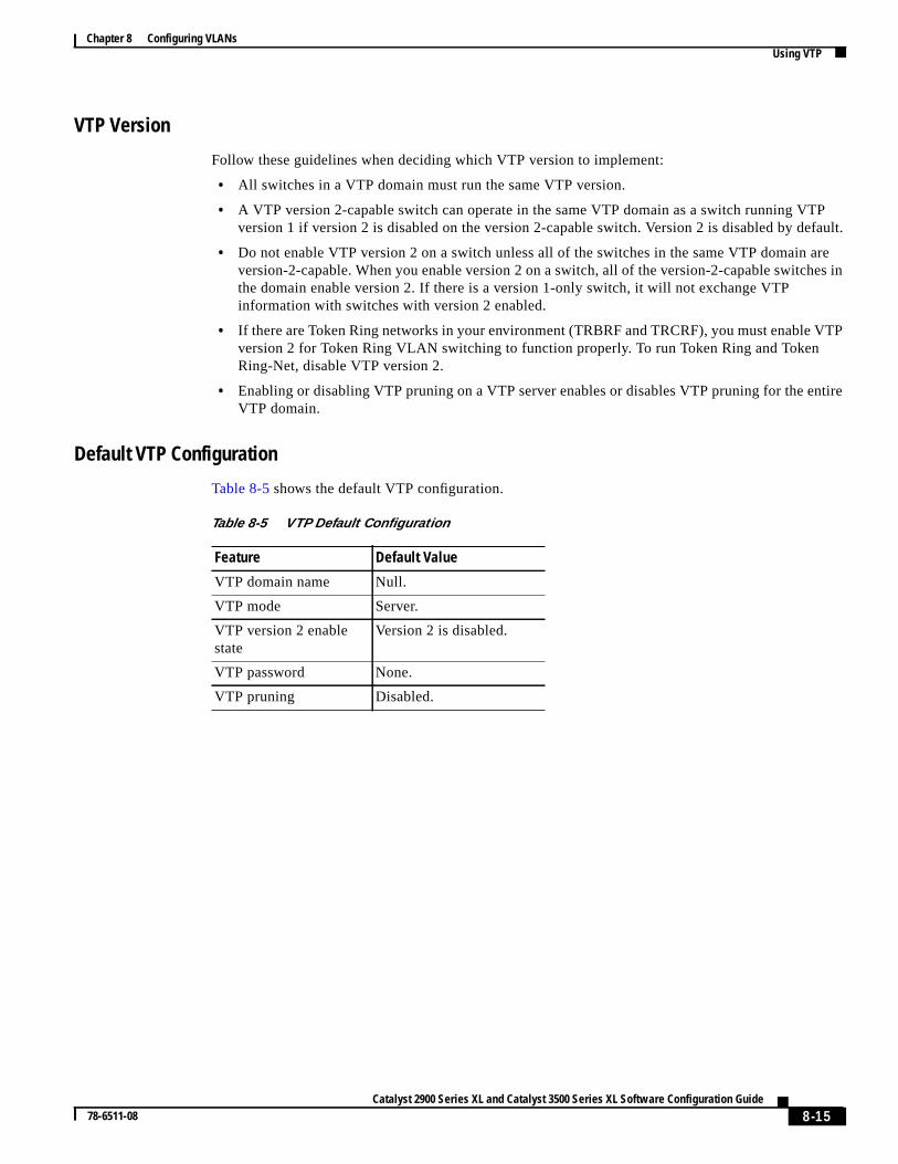
Table 8-5 shows the default VTP configuration.
Table 8-5 VTP Default Configuration
Feature Default Value
VTP domain name Null.
VTP mode Server.
VTP version 2 enablestate
Version 2 is disabled.
VTP password None.
VTP pruning Disabled.
8-15Catalyst 2900 Series XL and Catalyst 3500 Series XL Software Configuration Guide
78-6511-08
Chapter 8 Configuring VLANsUsing VTP
ode.
EXEC
byd,
VTP
ated
ode:
8
e
Configuring VTPYou can configure VTP through the CLI by entering commands in the VLAN database command mWhen you enter theexit command in VLAN database mode, it applies all the commands that youentered. VTP messages are sent to other switches in the VTP domain, and you enter privileged mode.
If you are configuring VTP on a cluster member switch to a VLAN, first log in to the member switchusing the privileged EXECrcommand command. For more information on how to use this commanrefer to the switch command reference.
Note The Cisco IOS end and Ctrl-Z commands are not supported in VLAN database mode.
After you configure VTP, you must configure a trunk port so that the switch can send and receiveadvertisements. For more information, see the“How VLAN Trunks Work” section on page 8-26.
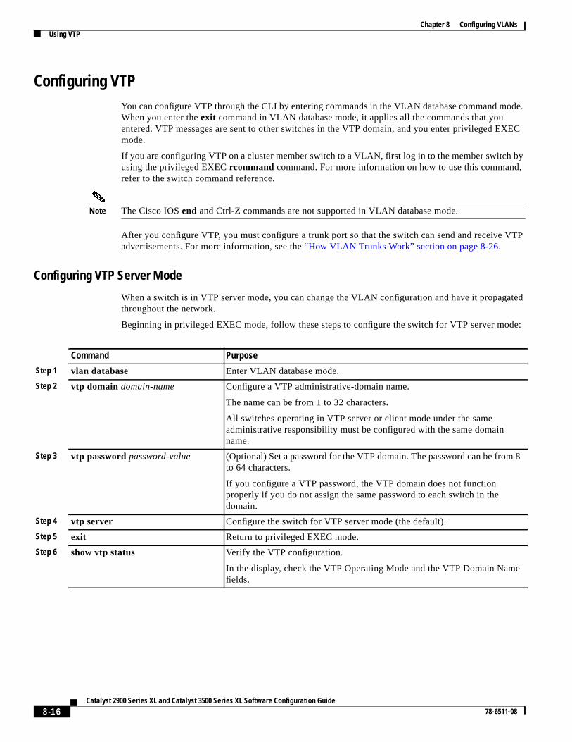
Configuring VTP Server Mode
When a switch is in VTP server mode, you can change the VLAN configuration and have it propagthroughout the network.
Beginning in privileged EXEC mode, follow these steps to configure the switch for VTP server m
Command Purpose
Step 1 vlan database Enter VLAN database mode.
Step 2 vtp domain domain-name Configure a VTP administrative-domain name.
The name can be from 1 to 32 characters.
All switches operating in VTP server or client mode under the sameadministrative responsibility must be configured with the same domainname.
Step 3 vtp passwordpassword-value (Optional) Set a password for the VTP domain. The password can be fromto 64 characters.
If you configure a VTP password, the VTP domain does not functionproperly if you do not assign the same password to each switch in thedomain.
Step 4 vtp server Configure the switch for VTP server mode (the default).
Step 5 exit Return to privileged EXEC mode.
Step 6 show vtp status Verify the VTP configuration.
In the display, check the VTP Operating Mode and the VTP Domain Namfields.
8-16Catalyst 2900 Series XL and Catalyst 3500 Series XL Software Configuration Guide
78-6511-08
Chapter 8 Configuring VLANsUsing VTP
h
o, itou
de:
r.
to
8
e
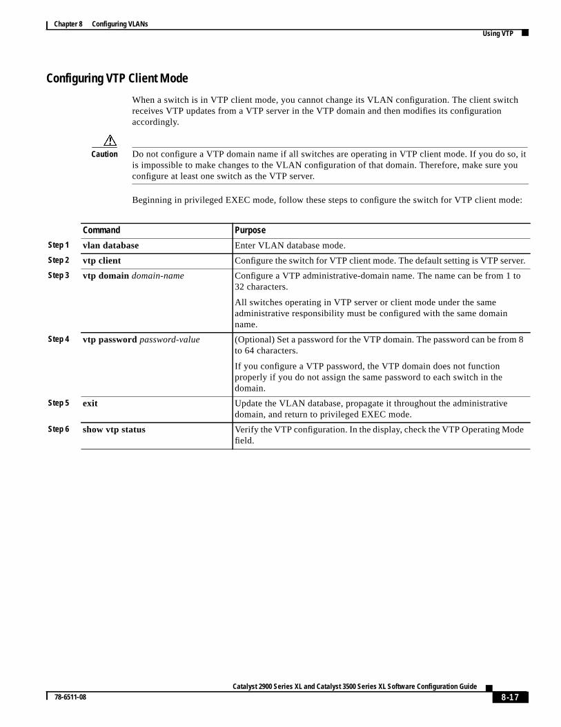
Configuring VTP Client Mode
When a switch is in VTP client mode, you cannot change its VLAN configuration. The client switcreceives VTP updates from a VTP server in the VTP domain and then modifies its configurationaccordingly.
Caution Do not configure a VTP domain name if all switches are operating in VTP client mode. If you do sis impossible to make changes to the VLAN configuration of that domain. Therefore, make sure yconfigure at least one switch as the VTP server.
Beginning in privileged EXEC mode, follow these steps to configure the switch for VTP client mo
Command Purpose
Step 1 vlan database Enter VLAN database mode.
Step 2 vtp client Configure the switch for VTP client mode. The default setting is VTP serve
Step 3 vtp domain domain-name Configure a VTP administrative-domain name. The name can be from 1 32 characters.
All switches operating in VTP server or client mode under the sameadministrative responsibility must be configured with the same domainname.
Step 4 vtp passwordpassword-value (Optional) Set a password for the VTP domain. The password can be fromto 64 characters.
If you configure a VTP password, the VTP domain does not functionproperly if you do not assign the same password to each switch in thedomain.
Step 5 exit Update the VLAN database, propagate it throughout the administrativedomain, and return to privileged EXEC mode.
Step 6 show vtp status Verify the VTP configuration. In the display, check the VTP Operating Modfield.
8-17Catalyst 2900 Series XL and Catalyst 3500 Series XL Software Configuration Guide
78-6511-08
Chapter 8 Configuring VLANsUsing VTP
witch.
links.
nt
rsion
eryevery
.
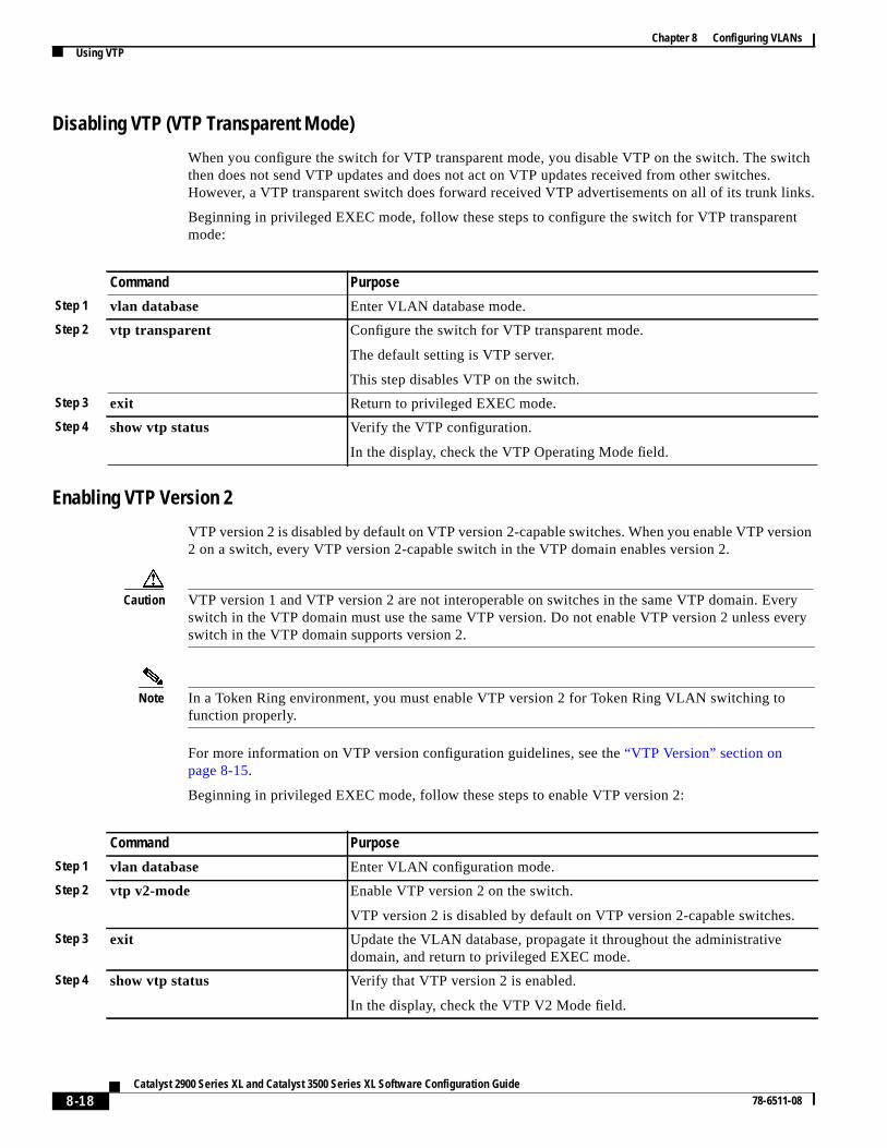
Disabling VTP (VTP Transparent Mode)
When you configure the switch for VTP transparent mode, you disable VTP on the switch. The sthen does not send VTP updates and does not act on VTP updates received from other switchesHowever, a VTP transparent switch does forward received VTP advertisements on all of its trunk
Beginning in privileged EXEC mode, follow these steps to configure the switch for VTP transparemode:
Enabling VTP Version 2
VTP version 2 is disabled by default on VTP version 2-capable switches. When you enable VTP ve2 on a switch, every VTP version 2-capable switch in the VTP domain enables version 2.
Caution VTP version 1 and VTP version 2 are not interoperable on switches in the same VTP domain. Evswitch in the VTP domain must use the same VTP version. Do not enable VTP version 2 unless switch in the VTP domain supports version 2.
Note In a Token Ring environment, you must enable VTP version 2 for Token Ring VLAN switching tofunction properly.
For more information on VTP version configuration guidelines, see the“VTP Version” section onpage 8-15.
Beginning in privileged EXEC mode, follow these steps to enable VTP version 2:
Command Purpose
Step 1 vlan database Enter VLAN database mode.
Step 2 vtp transparent Configure the switch for VTP transparent mode.
The default setting is VTP server.
This step disables VTP on the switch.
Step 3 exit Return to privileged EXEC mode.
Step 4 show vtp status Verify the VTP configuration.
In the display, check the VTP Operating Mode field.
Command Purpose
Step 1 vlan database Enter VLAN configuration mode.
Step 2 vtp v2-mode Enable VTP version 2 on the switch.
VTP version 2 is disabled by default on VTP version 2-capable switches
Step 3 exit Update the VLAN database, propagate it throughout the administrativedomain, and return to privileged EXEC mode.
Step 4 show vtp status Verify that VTP version 2 is enabled.
In the display, check the VTP V2 Mode field.
8-18Catalyst 2900 Series XL and Catalyst 3500 Series XL Software Configuration Guide
78-6511-08
Chapter 8 Configuring VLANsUsing VTP
afficode.
it is
re
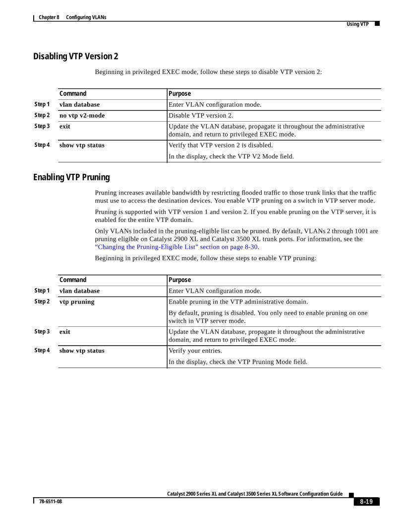
Disabling VTP Version 2
Beginning in privileged EXEC mode, follow these steps to disable VTP version 2:
Enabling VTP Pruning
Pruning increases available bandwidth by restricting flooded traffic to those trunk links that the trmust use to access the destination devices. You enable VTP pruning on a switch in VTP server m
Pruning is supported with VTP version 1 and version 2. If you enable pruning on the VTP server,enabled for the entire VTP domain.
Only VLANs included in the pruning-eligible list can be pruned. By default, VLANs 2 through 1001 apruning eligible on Catalyst 2900 XL and Catalyst 3500 XL trunk ports. For information, see the“Changing the Pruning-Eligible List” section on page 8-30.
Beginning in privileged EXEC mode, follow these steps to enable VTP pruning:
Command Purpose
Step 1 vlan database Enter VLAN configuration mode.
Step 2 no vtp v2-mode Disable VTP version 2.
Step 3 exit Update the VLAN database, propagate it throughout the administrativedomain, and return to privileged EXEC mode.
Step 4 show vtp status Verify that VTP version 2 is disabled.
In the display, check the VTP V2 Mode field.
Command Purpose
Step 1 vlan database Enter VLAN configuration mode.
Step 2 vtp pruning Enable pruning in the VTP administrative domain.
By default, pruning is disabled. You only need to enable pruning on oneswitch in VTP server mode.
Step 3 exit Update the VLAN database, propagate it throughout the administrativedomain, and return to privileged EXEC mode.
Step 4 show vtp status Verify your entries.
In the display, check the VTP Pruning Mode field.
8-19Catalyst 2900 Series XL and Catalyst 3500 Series XL Software Configuration Guide
78-6511-08
Chapter 8 Configuring VLANsVLANs in the VTP Database
t and
TP
,
r
ons,nagedese
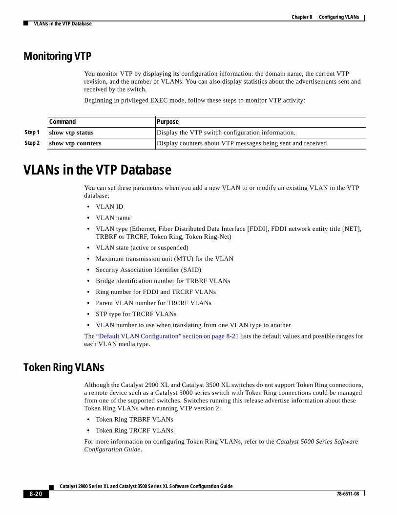
Monitoring VTPYou monitor VTP by displaying its configuration information: the domain name, the current VTPrevision, and the number of VLANs. You can also display statistics about the advertisements senreceived by the switch.
Beginning in privileged EXEC mode, follow these steps to monitor VTP activity:
VLANs in the VTP DatabaseYou can set these parameters when you add a new VLAN to or modify an existing VLAN in the Vdatabase:
• VLAN ID
• VLAN name
• VLAN type (Ethernet, Fiber Distributed Data Interface [FDDI], FDDI network entity title [NET]TRBRF or TRCRF, Token Ring, Token Ring-Net)
• VLAN state (active or suspended)
• Maximum transmission unit (MTU) for the VLAN
• Security Association Identifier (SAID)
• Bridge identification number for TRBRF VLANs
• Ring number for FDDI and TRCRF VLANs
• Parent VLAN number for TRCRF VLANs
• STP type for TRCRF VLANs
• VLAN number to use when translating from one VLAN type to another
The“Default VLAN Configuration” section on page 8-21lists the default values and possible ranges foeach VLAN media type.
Token Ring VLANsAlthough the Catalyst 2900 XL and Catalyst 3500 XL switches do not support Token Ring connectia remote device such as a Catalyst 5000 series switch with Token Ring connections could be mafrom one of the supported switches. Switches running this release advertise information about thToken Ring VLANs when running VTP version 2:
• Token Ring TRBRF VLANs
• Token Ring TRCRF VLANs
For more information on configuring Token Ring VLANs, refer to theCatalyst 5000 Series SoftwareConfiguration Guide.
Command Purpose
Step 1 show vtp status Display the VTP switch configuration information.
Step 2 show vtp counters Display counters about VTP messages being sent and received.
8-20Catalyst 2900 Series XL and Catalyst 3500 Series XL Software Configuration Guide
78-6511-08
Chapter 8 Configuring VLANsVLANs in the VTP Database
rt 64re
ode.
tn
e
VLAN Configuration GuidelinesFollow these guidelines when creating and modifying VLANs in your network:
• A maximum of 250 VLANs can be active on supported switches, but some models only suppoVLANs. If VTP reports that there are 254 active VLANs, 4 of the active VLANs (1002 to 1005) areserved for Token Ring and FDDI.
• Before you can create a VLAN, the switch must be in VTP server mode or VTP transparent mFor information on configuring VTP, see the“Configuring VTP” section on page 8-16.
• Switches running this release do not support Token Ring or FDDI media. The switch does noforward FDDI, FDDI-Net, TRCRF, or TRBRF traffic, but it does propagate the VLAN configuratiothrough VTP.
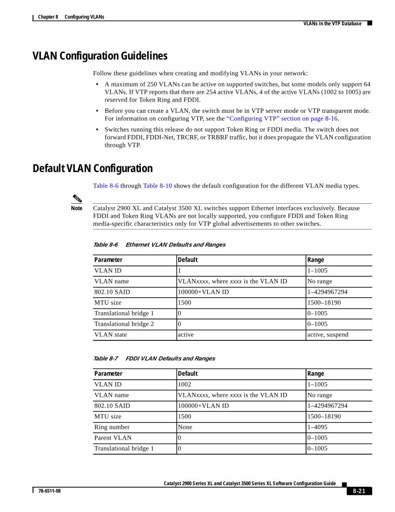
Default VLAN ConfigurationTable 8-6 throughTable 8-10 shows the default configuration for the different VLAN media types.
Note Catalyst 2900 XL and Catalyst 3500 XL switches support Ethernet interfaces exclusively. BecausFDDI and Token Ring VLANs are not locally supported, you configure FDDI and Token Ringmedia-specific characteristics only for VTP global advertisements to other switches.
Table 8-6 Ethernet VLAN Defaults and Ranges
Parameter Default Range
VLAN ID 1 1–1005
VLAN name VLANxxxx, wherexxxx is the VLAN ID No range
802.10 SAID 100000+VLAN ID 1–4294967294
MTU size 1500 1500–18190
Translational bridge 1 0 0–1005
Translational bridge 2 0 0–1005
VLAN state active active, suspend
Table 8-7 FDDI VLAN Defaults and Ranges
Parameter Default Range
VLAN ID 1002 1–1005
VLAN name VLANxxxx, wherexxxx is the VLAN ID No range
802.10 SAID 100000+VLAN ID 1–4294967294
MTU size 1500 1500–18190
Ring number None 1–4095
Parent VLAN 0 0–1005
Translational bridge 1 0 0–1005
8-21Catalyst 2900 Series XL and Catalyst 3500 Series XL Software Configuration Guide
78-6511-08
Chapter 8 Configuring VLANsVLANs in the VTP Database
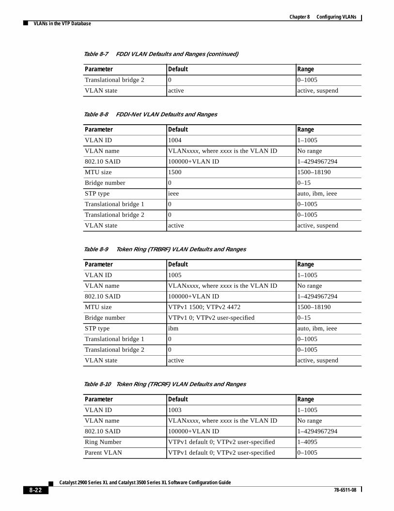
Translational bridge 2 0 0–1005
VLAN state active active, suspend
Table 8-8 FDDI-Net VLAN Defaults and Ranges
Parameter Default Range
VLAN ID 1004 1–1005
VLAN name VLANxxxx, wherexxxx is the VLAN ID No range
802.10 SAID 100000+VLAN ID 1–4294967294
MTU size 1500 1500–18190
Bridge number 0 0–15
STP type ieee auto, ibm, ieee
Translational bridge 1 0 0–1005
Translational bridge 2 0 0–1005
VLAN state active active, suspend
Table 8-9 Token Ring (TRBRF) VLAN Defaults and Ranges
Parameter Default Range
VLAN ID 1005 1–1005
VLAN name VLANxxxx, wherexxxx is the VLAN ID No range
802.10 SAID 100000+VLAN ID 1–4294967294
MTU size VTPv1 1500; VTPv2 4472 1500–18190
Bridge number VTPv1 0; VTPv2 user-specified 0–15
STP type ibm auto, ibm, ieee
Translational bridge 1 0 0–1005
Translational bridge 2 0 0–1005
VLAN state active active, suspend
Table 8-10 Token Ring (TRCRF) VLAN Defaults and Ranges
Parameter Default Range
VLAN ID 1003 1–1005
VLAN name VLANxxxx, wherexxxxis the VLAN ID No range
802.10 SAID 100000+VLAN ID 1–4294967294
Ring Number VTPv1 default 0; VTPv2 user-specified 1–4095
Parent VLAN VTPv1 default 0; VTPv2 user-specified 0–1005
Table 8-7 FDDI VLAN Defaults and Ranges (continued)
Parameter Default Range
8-22Catalyst 2900 Series XL and Catalyst 3500 Series XL Software Configuration Guide
78-6511-08
Chapter 8 Configuring VLANsVLANs in the VTP Database
TPn.dat,
o an
t file.d in
d andfile,
histion,
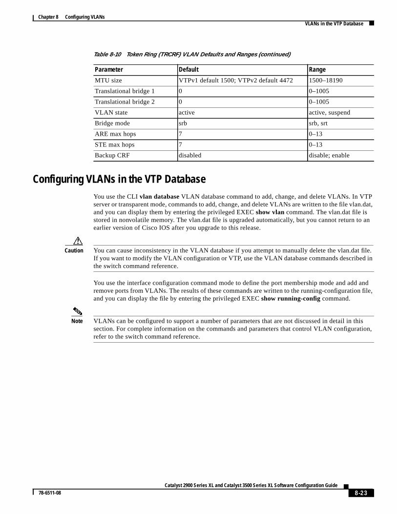
Configuring VLANs in the VTP DatabaseYou use the CLIvlan database VLAN database command to add, change, and delete VLANs. In Vserver or transparent mode, commands to add, change, and delete VLANs are written to the file vlaand you can display them by entering the privileged EXECshow vlan command. The vlan.dat file isstored in nonvolatile memory. The vlan.dat file is upgraded automatically, but you cannot return tearlier version of Cisco IOS after you upgrade to this release.
Caution You can cause inconsistency in the VLAN database if you attempt to manually delete the vlan.daIf you want to modify the VLAN configuration or VTP, use the VLAN database commands describethe switch command reference.
You use the interface configuration command mode to define the port membership mode and adremove ports from VLANs. The results of these commands are written to the running-configurationand you can display the file by entering the privileged EXECshow running-config command.
Note VLANs can be configured to support a number of parameters that are not discussed in detail in tsection. For complete information on the commands and parameters that control VLAN configurarefer to the switch command reference.
MTU size VTPv1 default 1500; VTPv2 default 4472 1500–18190
Translational bridge 1 0 0–1005
Translational bridge 2 0 0–1005
VLAN state active active, suspend
Bridge mode srb srb, srt
ARE max hops 7 0–13
STE max hops 7 0–13
Backup CRF disabled disable; enable
Table 8-10 Token Ring (TRCRF) VLAN Defaults and Ranges (continued)
Parameter Default Range
8-23Catalyst 2900 Series XL and Catalyst 3500 Series XL Software Configuration Guide
78-6511-08
Chapter 8 Configuring VLANsVLANs in the VTP Database
Nsigned
d
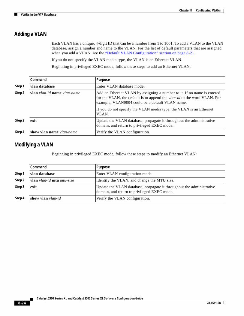
Adding a VLAN
Each VLAN has a unique, 4-digit ID that can be a number from 1 to 1001. To add a VLAN to the VLAdatabase, assign a number and name to the VLAN. For the list of default parameters that are aswhen you add a VLAN, see the“Default VLAN Configuration” section on page 8-21.
If you do not specify the VLAN media type, the VLAN is an Ethernet VLAN.
Beginning in privileged EXEC mode, follow these steps to add an Ethernet VLAN:
Modifying a VLAN
Beginning in privileged EXEC mode, follow these steps to modify an Ethernet VLAN:
Command Purpose
Step 1 vlan database Enter VLAN database mode.
Step 2 vlan vlan-id namevlan-name Add an Ethernet VLAN by assigning a number to it. If no name is enterefor the VLAN, the default is to append thevlan-id to the word VLAN. Forexample, VLAN0004 could be a default VLAN name.
If you do not specify the VLAN media type, the VLAN is an EthernetVLAN.
Step 3 exit Update the VLAN database, propagate it throughout the administrativedomain, and return to privileged EXEC mode.
Step 4 show vlan namevlan-name Verify the VLAN configuration.
Command Purpose
Step 1 vlan database Enter VLAN configuration mode.
Step 2 vlan vlan-id mtu mtu-size Identify the VLAN, and change the MTU size.
Step 3 exit Update the VLAN database, propagate it throughout the administrativedomain, and return to privileged EXEC mode.
Step 4 show vlanvlan-id Verify the VLAN configuration.
8-24Catalyst 2900 Series XL and Catalyst 3500 Series XL Software Configuration Guide
78-6511-08
Chapter 8 Configuring VLANsVLANs in the VTP Database
llde,
r
iated
nter
ase:
to
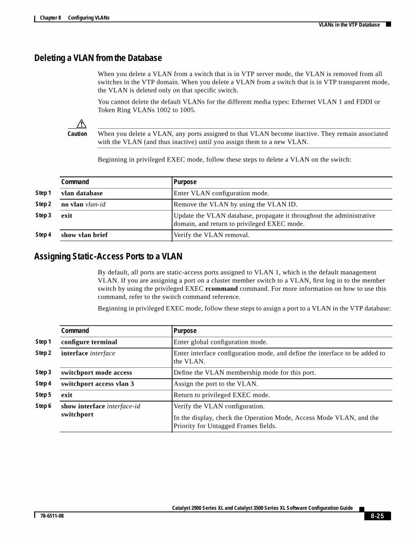
Deleting a VLAN from the Database
When you delete a VLAN from a switch that is in VTP server mode, the VLAN is removed from aswitches in the VTP domain. When you delete a VLAN from a switch that is in VTP transparent mothe VLAN is deleted only on that specific switch.
You cannot delete the default VLANs for the different media types: Ethernet VLAN 1 and FDDI oToken Ring VLANs 1002 to 1005.
Caution When you delete a VLAN, any ports assigned to that VLAN become inactive. They remain assocwith the VLAN (and thus inactive) until you assign them to a new VLAN.
Beginning in privileged EXEC mode, follow these steps to delete a VLAN on the switch:
Assigning Static-Access Ports to a VLAN
By default, all ports are static-access ports assigned to VLAN 1, which is the default managemeVLAN. If you are assigning a port on a cluster member switch to a VLAN, first log in to the membswitch by using the privileged EXECrcommand command. For more information on how to use thiscommand, refer to the switch command reference.
Beginning in privileged EXEC mode, follow these steps to assign a port to a VLAN in the VTP datab
Command Purpose
Step 1 vlan database Enter VLAN configuration mode.
Step 2 no vlan vlan-id Remove the VLAN by using the VLAN ID.
Step 3 exit Update the VLAN database, propagate it throughout the administrativedomain, and return to privileged EXEC mode.
Step 4 show vlan brief Verify the VLAN removal.
Command Purpose
Step 1 configure terminal Enter global configuration mode.
Step 2 interface interface Enter interface configuration mode, and define the interface to be addedthe VLAN.
Step 3 switchport mode access Define the VLAN membership mode for this port.
Step 4 switchport access vlan 3 Assign the port to the VLAN.
Step 5 exit Return to privileged EXEC mode.
Step 6 show interfaceinterface-idswitchport
Verify the VLAN configuration.
In the display, check the Operation Mode, Access Mode VLAN, and thePriority for Untagged Frames fields.
8-25Catalyst 2900 Series XL and Catalyst 3500 Series XL Software Configuration Guide
78-6511-08
Chapter 8 Configuring VLANsHow VLAN Trunks Work
s andrk.r
the
in theur
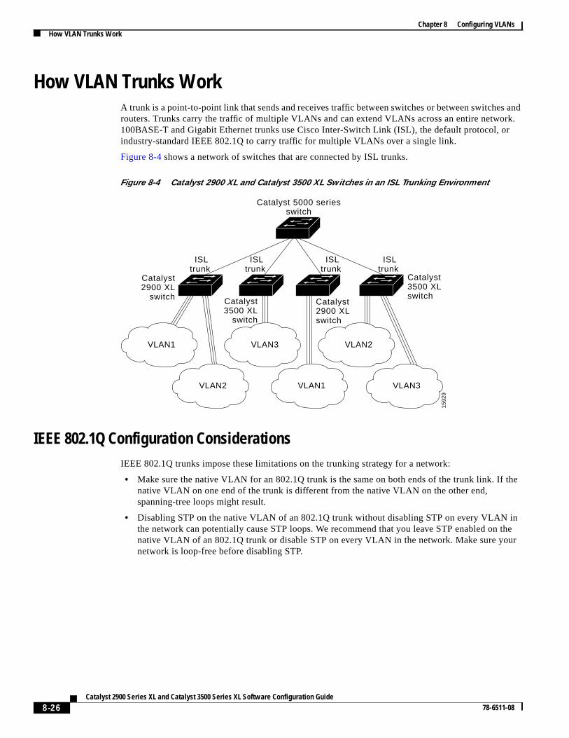
How VLAN Trunks WorkA trunk is a point-to-point link that sends and receives traffic between switches or between switcherouters. Trunks carry the traffic of multiple VLANs and can extend VLANs across an entire netwo100BASE-T and Gigabit Ethernet trunks use Cisco Inter-Switch Link (ISL), the default protocol, oindustry-standard IEEE 802.1Q to carry traffic for multiple VLANs over a single link.
Figure 8-4 shows a network of switches that are connected by ISL trunks.
Figure 8-4 Catalyst 2900 XL and Catalyst 3500 XL Switches in an ISL Trunking Environment
IEEE 802.1Q Configuration ConsiderationsIEEE 802.1Q trunks impose these limitations on the trunking strategy for a network:
• Make sure the native VLAN for an 802.1Q trunk is the same on both ends of the trunk link. Ifnative VLAN on one end of the trunk is different from the native VLAN on the other end,spanning-tree loops might result.
• Disabling STP on the native VLAN of an 802.1Q trunk without disabling STP on every VLANthe network can potentially cause STP loops. We recommend that you leave STP enabled onnative VLAN of an 802.1Q trunk or disable STP on every VLAN in the network. Make sure yonetwork is loop-free before disabling STP.
Catalyst 5000 seriesswitch
Catalyst2900 XL
switch Catalyst3500 XL
switch
Catalyst2900 XL switch
Catalyst 3500 XLswitch
VLAN2
VLAN3VLAN1
VLAN1
VLAN2
VLAN3
ISLtrunk
ISLtrunk
ISLtrunk
ISLtrunk
1592
9
8-26Catalyst 2900 Series XL and Catalyst 3500 Series XL Software Configuration Guide
78-6511-08
Chapter 8 Configuring VLANsHow VLAN Trunks Work
tor
rk
nn
ps,
ort
ef
l
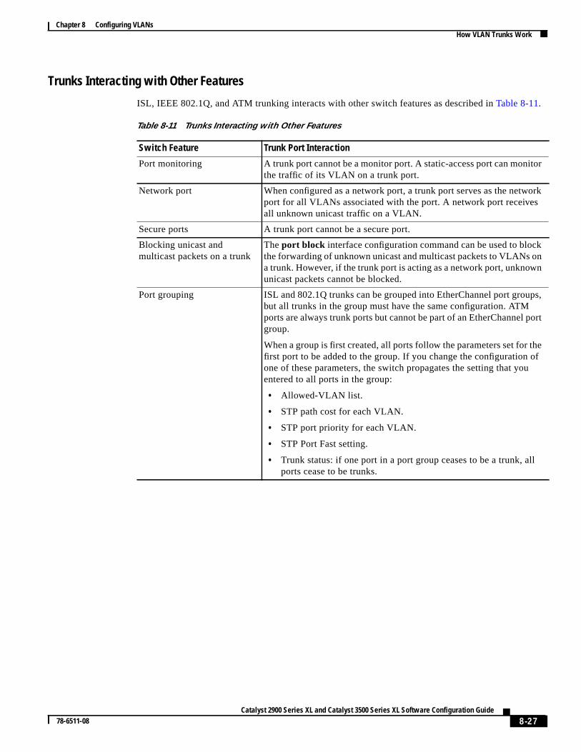
Trunks Interacting with Other Features
ISL, IEEE 802.1Q, and ATM trunking interacts with other switch features as described inTable 8-11.
Table 8-11 Trunks Interacting with Other Features
Switch Feature Trunk Port Interaction
Port monitoring A trunk port cannot be a monitor port. A static-access port can monithe traffic of its VLAN on a trunk port.
Network port When configured as a network port, a trunk port serves as the netwoport for all VLANs associated with the port. A network port receivesall unknown unicast traffic on a VLAN.
Secure ports A trunk port cannot be a secure port.
Blocking unicast andmulticast packets on a trunk
Theport block interface configuration command can be used to blockthe forwarding of unknown unicast and multicast packets to VLANs oa trunk. However, if the trunk port is acting as a network port, unknowunicast packets cannot be blocked.
Port grouping ISL and 802.1Q trunks can be grouped into EtherChannel port groubut all trunks in the group must have the same configuration. ATMports are always trunk ports but cannot be part of an EtherChannel pgroup.
When a group is first created, all ports follow the parameters set for thfirst port to be added to the group. If you change the configuration oone of these parameters, the switch propagates the setting that youentered to all ports in the group:
• Allowed-VLAN list.
• STP path cost for each VLAN.
• STP port priority for each VLAN.
• STP Port Fast setting.
• Trunk status: if one port in a port group ceases to be a trunk, alports cease to be trunks.
8-27Catalyst 2900 Series XL and Catalyst 3500 Series XL Software Configuration Guide
78-6511-08
Chapter 8 Configuring VLANsHow VLAN Trunks Work
nk
nk porttch.
runk
TP),or
t does
e.
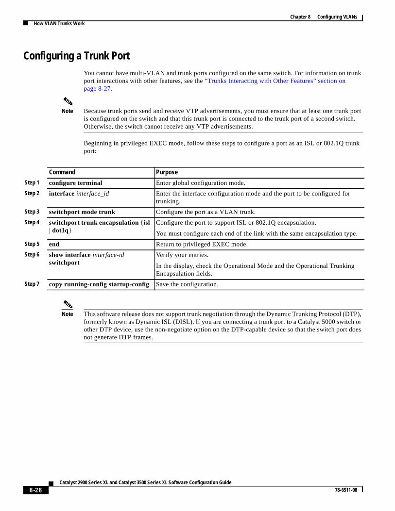
Configuring a Trunk PortYou cannot have multi-VLAN and trunk ports configured on the same switch. For information on truport interactions with other features, see the“Trunks Interacting with Other Features” section onpage 8-27.
Note Because trunk ports send and receive VTP advertisements, you must ensure that at least one truis configured on the switch and that this trunk port is connected to the trunk port of a second swiOtherwise, the switch cannot receive any VTP advertisements.
Beginning in privileged EXEC mode, follow these steps to configure a port as an ISL or 802.1Q tport:
Note This software release does not support trunk negotiation through the Dynamic Trunking Protocol (Dformerly known as Dynamic ISL (DISL). If you are connecting a trunk port to a Catalyst 5000 switchother DTP device, use the non-negotiate option on the DTP-capable device so that the switch pornot generate DTP frames.
Command Purpose
Step 1 configure terminal Enter global configuration mode.
Step 2 interface interface_id Enter the interface configuration mode and the port to be configured fortrunking.
Step 3 switchport mode trunk Configure the port as a VLAN trunk.
Step 4 switchport trunk encapsulation { isl| dot1q}
Configure the port to support ISL or 802.1Q encapsulation.
You must configure each end of the link with the same encapsulation typ
Step 5 end Return to privileged EXEC mode.
Step 6 show interfaceinterface-idswitchport
Verify your entries.
In the display, check the Operational Mode and the Operational TrunkingEncapsulation fields.
Step 7 copy running-config startup-config Save the configuration.
8-28Catalyst 2900 Series XL and Catalyst 3500 Series XL Software Configuration Guide
78-6511-08
Chapter 8 Configuring VLANsHow VLAN Trunks Work
s,tinge
,theek
.1Q
.
ge
Disabling a Trunk PortYou can disable trunking on a port by returning it to its default static-access mode.
Beginning in privileged EXEC mode, follow these steps to disable trunking on a port:
Defining the Allowed VLANs on a TrunkBy default, a trunk port sends to and receives traffic from all VLANs in the VLAN database. All VLAN1 to 1005, are allowed on each trunk. However, you can remove VLANs from the allowed list, preventraffic from those VLANs from passing over the trunk. To restrict the traffic a trunk carries, use thremovevlan-list parameter to remove specific VLANs from the allowed list.
A trunk port can become a member of a VLAN if the VLAN is enabled, if VTP knows of the VLANand if the VLAN is in the allowed list for the port. When VTP detects a newly enabled VLAN and VLAN is in the allowed list for a trunk port, the trunk port automatically becomes a member of thenabled VLAN. When VTP detects a new VLAN and the VLAN is not in the allowed list for a trunport, the trunk port does not become a member of the new VLAN.
Beginning in privileged EXEC mode, follow these steps to modify the allowed list of a ISL or 802trunk:
Command Purpose
Step 1 configure terminal Enter global configuration mode.
Step 2 interface interface_id Enter the interface configuration mode and the port to be added to theVLAN.
Step 3 no switchport mode Return the port to its default static-access mode.
Step 4 end Return to privileged EXEC.
Step 5 show interfaceinterface-idswitchport
Verify your entries.
In the display, check the Negotiation of Trunking field.
Command Purpose
Step 1 configure terminal Enter global configuration mode.
Step 2 interface interface_id Enter interface configuration mode and the port to be added to the VLAN
Step 3 switchport mode trunk Configure VLAN membership mode for trunks.
Step 4 switchport trunk allowed vlanremovevlan-list
Define the VLANs that arenot allowed to send and receive on the port.
Thevlan-list parameter is a range of VLAN IDs Separate nonconsecutiveVLAN IDs with a comma and no spaces; use a hyphen to designate a ranof IDs. Valid IDs are from 2 to 1001.
Step 5 end Return to privileged EXEC.
Step 6 show interfaceinterface-idswitchport allowed-vlan
Verify your entries.
Step 7 copy running-config startup-config Save the configuration.
8-29Catalyst 2900 Series XL and Catalyst 3500 Series XL Software Configuration Guide
78-6511-08
Chapter 8 Configuring VLANsHow VLAN Trunks Work
list
fault,is
AN.
Q
nt
Changing the Pruning-Eligible ListThe pruning-eligible list applies only to trunk ports. Each trunk port has its own eligibility list. VTPPruning must be enabled for this procedure to take effect. The“Enabling VTP Pruning” section onpage 8-19 describes how to enable VTP pruning.
Beginning in privileged EXEC mode, follow these steps to remove VLANs from the pruning-eligibleon a trunk port:
Configuring the Native VLAN for Untagged TrafficA trunk port configured with 802.1Q tagging can receive both tagged and untagged traffic. By dethe switch forwards untagged traffic with the native VLAN configured for the port. The native VLANVLAN 1 by default. For information about 802.1Q configuration issues, see the“IEEE 802.1QConfiguration Considerations” section on page 8-26.
Note The native VLAN can be assigned any VLAN ID, and it is not dependent on the management VL
Beginning in privileged EXEC mode, follow these steps to configure the native VLAN on an 802.1trunk:
If a packet has a VLAN ID that is the same as the outgoing port native VLAN ID, the packet is seuntagged; otherwise, the switch sends the packet with a tag.
Command Purpose
Step 1 configure terminal Enter global configuration mode.
Step 2 interface interface-id Enter interface configuration mode, and select the trunk port for whichVLANs should be pruned.
Step 3 switchport trunk pruning vlanremovevlan-id
Enter the VLANs to be removed from the pruning-eligible list.
Separate nonconsecutive VLAN IDs with a comma and no spaces; use ahyphen to designate a range of IDs. Valid IDs are from 2 to 1001.
VLANs that are pruning-ineligible receive flooded traffic.
Step 4 exit Return to privileged EXEC mode.
Step 5 show interfaceinterface-idswitchport
Verify your settings.
Command Purpose
Step 1 configure terminal Enter global configuration mode.
Step 2 interface interface-id Enter interface configuration mode, and define the interface that isconfigured as the 802.1Q trunk.
Step 3 switchport trunk native vlan vlan-id Configure the VLAN that is sending and receiving untagged traffic on thetrunk port.
Valid IDs are from 1 to 1001.
Step 4 show interfaceinterface-idswitchport
Verify your settings.
8-30Catalyst 2900 Series XL and Catalyst 3500 Series XL Software Configuration Guide
78-6511-08
Chapter 8 Configuring VLANsConfiguring 802.1p Class of Service
Ec fromes to
h thein the
each anythe lastt are
ed.
n thiswhen
upport
.
.
Configuring 802.1p Class of ServiceThe Catalyst 2900 XL and Catalyst 3500 XL switches provide quality of service (QoS)-based IEE802.1p class of service (CoS) values. QoS uses classification and scheduling to send network traffithe switch in a predictable manner. QoS classifies frames by assigning priority-indexed CoS valuthem and gives preference to higher-priority traffic such as telephone calls.
How Class of Service WorksBefore you set up 802.1p CoS on a Catalyst 2900 XL or Catalyst 3500 XL switch that operates witCatalyst 6000 family of switches, refer to the Catalyst 6000 documentation. There are differences802.1p implementation, and they should be understood to ensure compatibility.
Port Priority
Frames received from users in the administratively-defined VLANs are classified ortaggedfortransmission to other devices. Based on rules you define, a unique identifier (the tag) is inserted inframe header before it is forwarded. The tag is examined and understood by each device beforebroadcasts or transmissions to other switches, routers, or end stations. When the frame reachesswitch or router, the tag is removed before the frame is resent to the target end station. VLANs thaassigned on trunk or access ports without identification or a tag are callednative or untagged frames.
For ISL or IEEE 802.1Q frames with tag information, the priority value from the header frame is usFor native frames, the default priority of the input port is used.
Port Scheduling
Each port on the switch has a single receive queue buffer (theingressport) for incoming traffic. Whenan untagged frame arrives, it is assigned the value of the port as its port default priority. You assigvalue by using the CLI or CMS software. A tagged frame continues to use its assigned CoS valueit passes through the ingress port.
CoS configures each transmit port (theegressport) with a normal-priority transmit queue and ahigh-priority transmit queue, depending on the frame tag or the port information.Frames in thenormal-priority queue are forwarded only after frames in the high-priority queue are forwarded.
Table 8-12 shows the two categories of switch transmit queues.
Table 8-12 Transmit Queue Information
Transmit Queue Category1
1. Catalyst 2900 XL switches with 4 MB of DRAM and the WS-X2914-XL and the WS-X2922-XL modules only have one transmit queue and do not sQoS.
Transmit Queues
Catalyst 2900 XL switches,Catalyst 2900 XL Ethernet modules(802.1p user priority)
Frames with a priority value of 0 through 3 are sent to a normal-priority queue
Frames with a priority value of 4 through 7 are sent to a high-priority queue.
Catalyst 3500 XL switches, GigabitEthernet modules (802.1p user priority)
Frames with a priority value of 0 through 3 are sent to a normal-priority queue
Frames with a priority value of 4 through 7 are sent to a high-priority queue.
8-31Catalyst 2900 Series XL and Catalyst 3500 Series XL Software Configuration Guide
78-6511-08
Chapter 8 Configuring VLANsLoad Sharing Using STP
e)
ps,ffic
dr load two
rt ist thea
for
ured
l
s
Configuring the CoS Port PrioritiesBeginning in privileged EXEC mode, follow these steps to set the port priority for untagged (nativEthernet frames:
Load Sharing Using STPLoad sharing divides the bandwidth supplied by parallel trunks connecting switches. To avoid looSTP normally blocks all but one parallel link between switches. With load sharing, you divide the trabetween the links according to which VLAN the traffic belongs.
You configure load sharing on trunk ports by using STP port priorities or STP path costs. For loasharing using STP port priorities, both load-sharing links must be connected to the same switch. Fosharing using STP path costs, each load-sharing link can be connected to the same switch or todifferent switches.
For more information about STP, see the“Configuring STP” section on page 6-33.
Load Sharing Using STP Port PrioritiesWhen two ports on the same switch form a loop, the STP port priority setting determines which poenabled and which port is in standby mode. You can set the priorities on a parallel trunk port so thaport carries all the traffic for a given VLAN. The trunk port with the higher priority (lower values) forVLAN is forwarding traffic for that VLAN. The trunk port with the lower priority (higher values) for thesame VLAN remains in a blocking state for that VLAN. One trunk port sends or receives all trafficthe VLAN.
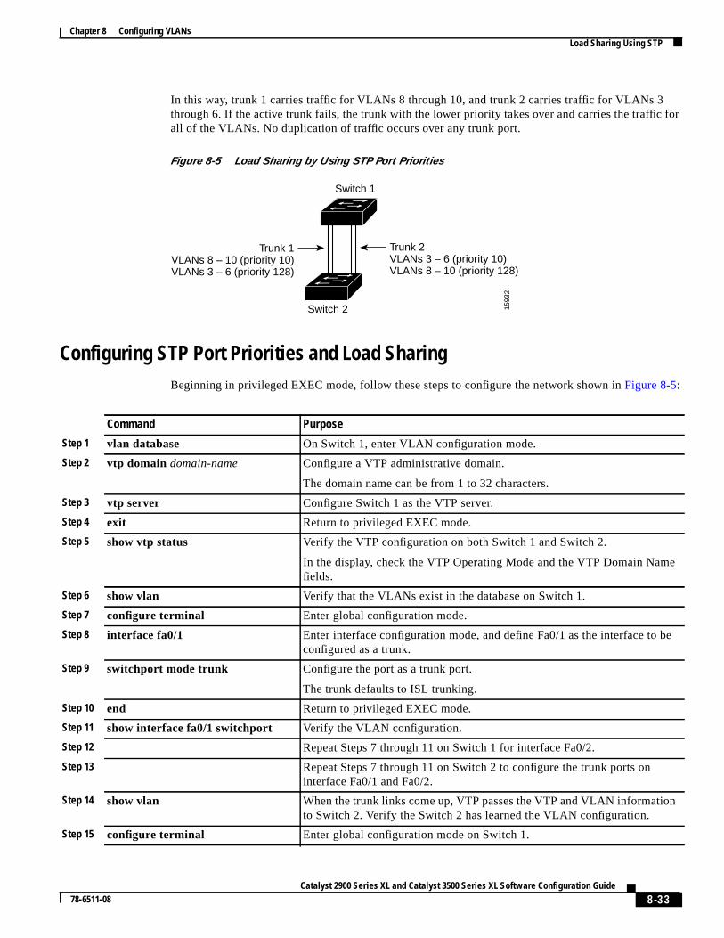
Figure 8-5shows two trunks connecting supported switches. In this example, the switches are configas follows:
• VLANs 8 through 10 are assigned a port priority of 10 on trunk 1.
• VLANs 3 through 6 retain the default port priority of 128 on trunk 1.
• VLANs 3 through 6 are assigned a port priority of 10 on trunk 2.
• VLANs 8 through 10 retain the default port priority of 128 on trunk 2.
Command Purpose
Step 1 configure terminal Enter global configuration mode.
Step 2 interface interface Enter the interface to be configured.
Step 3 switchport priority defaultdefault-priority-id
Set the port priority on the interface.
If you assign a priority level from 0 to 3, frames are forwarded to the normapriority queue of the output port.
If you assign a priority level from 4 to 7, frames are forwarded to thehigh-priority queue of the output port.
Step 4 end Return to privileged EXEC mode.
Step 5 show interfaceinterface-idswitchport
Verify your entries. In the display, check the Priority for Untagged Framefield.
8-32Catalyst 2900 Series XL and Catalyst 3500 Series XL Software Configuration Guide
78-6511-08
Chapter 8 Configuring VLANsLoad Sharing Using STP
for
e
be
n
In this way, trunk 1 carries traffic for VLANs 8 through 10, and trunk 2 carries traffic for VLANs 3through 6. If the active trunk fails, the trunk with the lower priority takes over and carries the trafficall of the VLANs. No duplication of traffic occurs over any trunk port.
Figure 8-5 Load Sharing by Using STP Port Priorities
Configuring STP Port Priorities and Load SharingBeginning in privileged EXEC mode, follow these steps to configure the network shown inFigure 8-5:
1593
2
Switch 1
Switch 2
Trunk 2VLANs 3 – 6 (priority 10)VLANs 8 – 10 (priority 128)
Trunk 1VLANs 8 – 10 (priority 10)VLANs 3 – 6 (priority 128)
Command Purpose
Step 1 vlan database On Switch 1, enter VLAN configuration mode.
Step 2 vtp domain domain-name Configure a VTP administrative domain.
The domain name can be from 1 to 32 characters.
Step 3 vtp server Configure Switch 1 as the VTP server.
Step 4 exit Return to privileged EXEC mode.
Step 5 show vtp status Verify the VTP configuration on both Switch 1 and Switch 2.
In the display, check the VTP Operating Mode and the VTP Domain Namfields.
Step 6 show vlan Verify that the VLANs exist in the database on Switch 1.
Step 7 configure terminal Enter global configuration mode.
Step 8 interface fa0/1 Enter interface configuration mode, and define Fa0/1 as the interface to configured as a trunk.
Step 9 switchport mode trunk Configure the port as a trunk port.
The trunk defaults to ISL trunking.
Step 10 end Return to privileged EXEC mode.
Step 11 show interface fa0/1 switchport Verify the VLAN configuration.
Step 12 Repeat Steps 7 through 11 on Switch 1 for interface Fa0/2.
Step 13 Repeat Steps 7 through 11 on Switch 2 to configure the trunk ports oninterface Fa0/1 and Fa0/2.
Step 14 show vlan When the trunk links come up, VTP passes the VTP and VLAN informatioto Switch 2. Verify the Switch 2 has learned the VLAN configuration.
Step 15 configure terminal Enter global configuration mode on Switch 1.
8-33Catalyst 2900 Series XL and Catalyst 3500 Series XL Software Configuration Guide
78-6511-08
Chapter 8 Configuring VLANsLoad Sharing Using STP
ndauset link.
d as
TP
TP
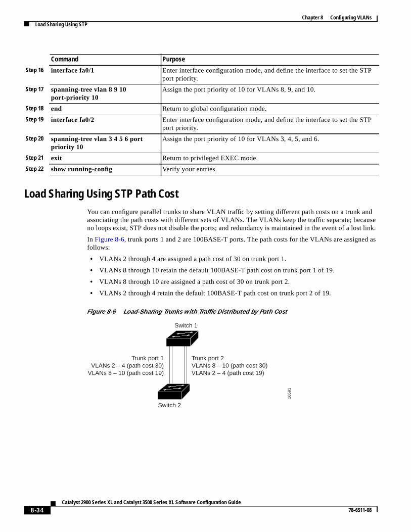
Load Sharing Using STP Path CostYou can configure parallel trunks to share VLAN traffic by setting different path costs on a trunk aassociating the path costs with different sets of VLANs. The VLANs keep the traffic separate; becno loops exist, STP does not disable the ports; and redundancy is maintained in the event of a los
In Figure 8-6, trunk ports 1 and 2 are 100BASE-T ports. The path costs for the VLANs are assignefollows:
• VLANs 2 through 4 are assigned a path cost of 30 on trunk port 1.
• VLANs 8 through 10 retain the default 100BASE-T path cost on trunk port 1 of 19.
• VLANs 8 through 10 are assigned a path cost of 30 on trunk port 2.
• VLANs 2 through 4 retain the default 100BASE-T path cost on trunk port 2 of 19.
Figure 8-6 Load-Sharing Trunks with Traffic Distributed by Path Cost
Step 16 interface fa0/1 Enter interface configuration mode, and define the interface to set the Sport priority.
Step 17 spanning-tree vlan 8 9 10port-priority 10
Assign the port priority of 10 for VLANs 8, 9, and 10.
Step 18 end Return to global configuration mode.
Step 19 interface fa0/2 Enter interface configuration mode, and define the interface to set the Sport priority.
Step 20 spanning-tree vlan 3 4 5 6 portpriority 10
Assign the port priority of 10 for VLANs 3, 4, 5, and 6.
Step 21 exit Return to privileged EXEC mode.
Step 22 show running-config Verify your entries.
Command Purpose
1659
1
Switch 1
Switch 2
Trunk port 1VLANs 2 – 4 (path cost 30)
VLANs 8 – 10 (path cost 19)
Trunk port 2VLANs 8 – 10 (path cost 30)VLANs 2 – 4 (path cost 19)
8-34Catalyst 2900 Series XL and Catalyst 3500 Series XL Software Configuration Guide
78-6511-08
Chapter 8 Configuring VLANsLoad Sharing Using STP
be
as
n.
set
/1
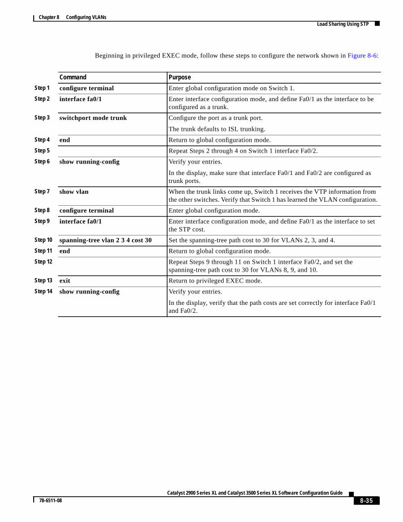
Beginning in privileged EXEC mode, follow these steps to configure the network shown inFigure 8-6:
Command Purpose
Step 1 configure terminal Enter global configuration mode on Switch 1.
Step 2 interface fa0/1 Enter interface configuration mode, and define Fa0/1 as the interface to configured as a trunk.
Step 3 switchport mode trunk Configure the port as a trunk port.
The trunk defaults to ISL trunking.
Step 4 end Return to global configuration mode.
Step 5 Repeat Steps 2 through 4 on Switch 1 interface Fa0/2.
Step 6 show running-config Verify your entries.
In the display, make sure that interface Fa0/1 and Fa0/2 are configured trunk ports.
Step 7 show vlan When the trunk links come up, Switch 1 receives the VTP information fromthe other switches. Verify that Switch 1 has learned the VLAN configuratio
Step 8 configure terminal Enter global configuration mode.
Step 9 interface fa0/1 Enter interface configuration mode, and define Fa0/1 as the interface to the STP cost.
Step 10 spanning-tree vlan 2 3 4 cost 30 Set the spanning-tree path cost to 30 for VLANs 2, 3, and 4.
Step 11 end Return to global configuration mode.
Step 12 Repeat Steps 9 through 11 on Switch 1 interface Fa0/2, and set thespanning-tree path cost to 30 for VLANs 8, 9, and 10.
Step 13 exit Return to privileged EXEC mode.
Step 14 show running-config Verify your entries.
In the display, verify that the path costs are set correctly for interface Fa0and Fa0/2.
8-35Catalyst 2900 Series XL and Catalyst 3500 Series XL Software Configuration Guide
78-6511-08
Chapter 8 Configuring VLANsHow the VMPS Works
PS)QPervere
s the
inst
se.
ds
s
t one
ert and
CLI,
esses
theheamic
porterycketsigned
MPS
How the VMPS WorksA switch running this software release acts as a client to the VLAN Membership Policy Server (VMand communicates with it through the VLAN Query Protocol (VQP). When the VMPS receives a Vrequest from a client switch, it searches its database for a MAC-address-to-VLAN mapping. The sresponse is based on this mapping and whether or not the server is in secure mode. Secure moddetermines whether the server shuts down the port when a VLAN is not allowed on it or just denieport access to the VLAN.
In response to a request, the VMPS takes one of these actions:
• If the assigned VLAN is restricted to a group of ports, the VMPS verifies the requesting port agathis group and responds as follows:
– If the VLAN is allowed on the port, the VMPS sends the VLAN name to the client in respon
– If the VLAN is not allowed on the port, and the VMPS is not in secure mode, the VMPS senanaccess-deniedresponse.
– If the VLAN is not allowed on the port, and the VMPS is in secure mode, the VMPS sendaport-shutdownresponse.
• If the VLAN in the database does not match the current VLAN on the port and active hosts existhe port, the VMPS sends anaccess-denied or a port-shutdown response, depending on the securmode of the VMPS.
If the switch receives anaccess-denied response from the VMPS, it continues to block traffic from thMAC address to or from the port. The switch continues to monitor the packets directed to the posends a query to the VMPS when it identifies a new address. If the switch receives aport-shutdownresponse from the VMPS, it disables the port. The port must be manually reenabled by using theCluster Management software, or SNMP.
You can also use an explicit entry in the configuration table to deny access to specific MAC addrfor security reasons. If you enter thenonekeyword for the VLAN name, the VMPS sends anaccess-denied or port-shutdown response.
Dynamic Port VLAN MembershipA dynamic (nontrunking) port on the switch can belong to only one VLAN. When the link comes up,switch does not forward traffic to or from this port until the VMPS provides the VLAN assignment. TVMPS receives the source MAC address from the first packet of a new host connected to the dynport and attempts to match the MAC address to a VLAN in the VMPS database.
If there is a match, the VMPS sends the VLAN number for that port. If the client switch was notpreviously configured, it uses the domain name from the first VTP packet it receives on its trunk from the VMPS. If the client switch was previously configured, it includes its domain name in the qupacket to the VMPS to obtain its VLAN number. The VMPS verifies that the domain name in the pamatches its own domain name before accepting the request and responds to the client with the asVLAN number for the client.
If there is no match, the VMPS either denies the request or shuts down the port (depending on the Vsecure mode setting). For more information on possible VMPS responses, see the“How the VMPSWorks” section on page 8-36.
8-36Catalyst 2900 Series XL and Catalyst 3500 Series XL Software Configuration Guide
78-6511-08
Chapter 8 Configuring VLANsHow the VMPS Works
;e link. Anyed to
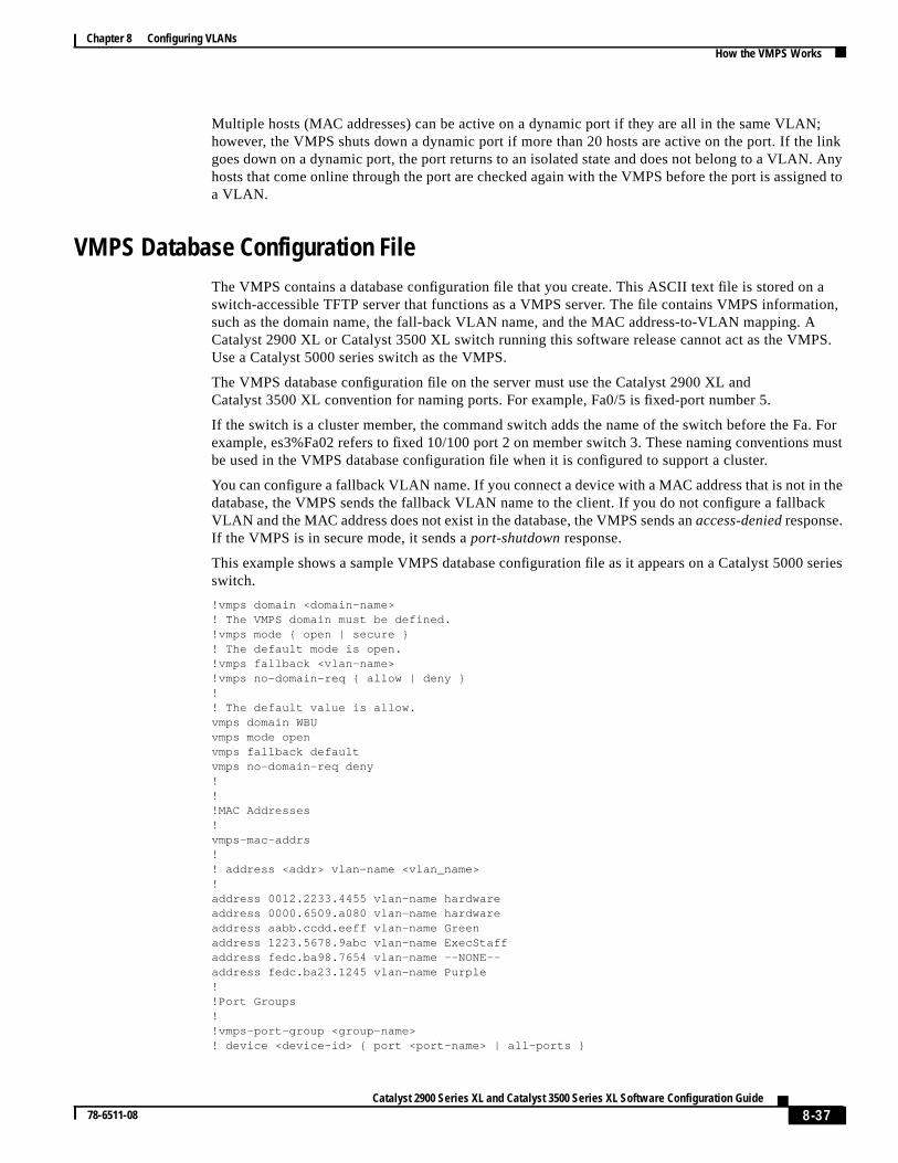
ation,
PS.
a. Formust
theck
series
Multiple hosts (MAC addresses) can be active on a dynamic port if they are all in the same VLANhowever, the VMPS shuts down a dynamic port if more than 20 hosts are active on the port. If thgoes down on a dynamic port, the port returns to an isolated state and does not belong to a VLANhosts that come online through the port are checked again with the VMPS before the port is assigna VLAN.
VMPS Database Configuration FileThe VMPS contains a database configuration file that you create. This ASCII text file is stored onswitch-accessible TFTP server that functions as a VMPS server. The file contains VMPS informasuch as the domain name, the fall-back VLAN name, and the MAC address-to-VLAN mapping. ACatalyst 2900 XL or Catalyst 3500 XL switch running this software release cannot act as the VMUse a Catalyst 5000 series switch as the VMPS.
The VMPS database configuration file on the server must use the Catalyst 2900 XL andCatalyst 3500 XL convention for naming ports. For example, Fa0/5 is fixed-port number 5.
If the switch is a cluster member, the command switch adds the name of the switch before the Fexample, es3%Fa02 refers to fixed 10/100 port 2 on member switch 3. These naming conventionsbe used in the VMPS database configuration file when it is configured to support a cluster.
You can configure a fallback VLAN name. If you connect a device with a MAC address that is not indatabase, the VMPS sends the fallback VLAN name to the client. If you do not configure a fallbaVLAN and the MAC address does not exist in the database, the VMPS sends anaccess-deniedresponse.If the VMPS is in secure mode, it sends aport-shutdown response.
This example shows a sample VMPS database configuration file as it appears on a Catalyst 5000switch.
!vmps domain <domain-name>! The VMPS domain must be defined.!vmps mode { open | secure }! The default mode is open.!vmps fallback <vlan-name>!vmps no-domain-req { allow | deny }!! The default value is allow.vmps domain WBUvmps mode openvmps fallback defaultvmps no-domain-req deny!!!MAC Addresses!vmps-mac-addrs!! address <addr> vlan-name <vlan_name>!address 0012.2233.4455 vlan-name hardwareaddress 0000.6509.a080 vlan-name hardwareaddress aabb.ccdd.eeff vlan-name Greenaddress 1223.5678.9abc vlan-name ExecStaffaddress fedc.ba98.7654 vlan-name --NONE--address fedc.ba23.1245 vlan-name Purple!!Port Groups!!vmps-port-group <group-name>! device <device-id> { port <port-name> | all-ports }
8-37Catalyst 2900 Series XL and Catalyst 3500 Series XL Software Configuration Guide
78-6511-08
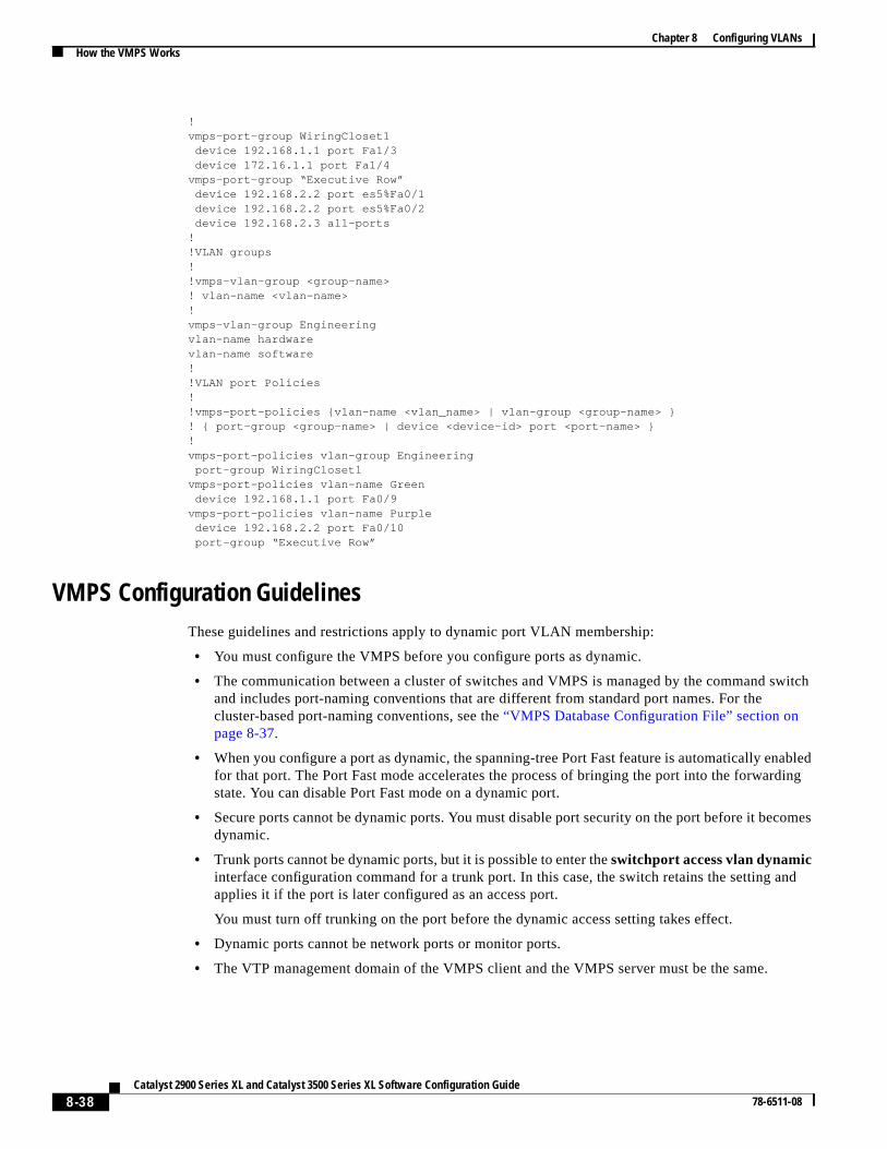
Chapter 8 Configuring VLANsHow the VMPS Works
witch
abledding
omes
nd
!vmps-port-group WiringCloset1 device 192.168.1.1 port Fa1/3 device 172.16.1.1 port Fa1/4vmps-port-group “Executive Row” device 192.168.2.2 port es5%Fa0/1 device 192.168.2.2 port es5%Fa0/2 device 192.168.2.3 all-ports!!VLAN groups!!vmps-vlan-group <group-name>! vlan-name <vlan-name>!vmps-vlan-group Engineeringvlan-name hardwarevlan-name software!!VLAN port Policies!!vmps-port-policies {vlan-name <vlan_name> | vlan-group <group-name> }! { port-group <group-name> | device <device-id> port <port-name> }!vmps-port-policies vlan-group Engineering port-group WiringCloset1vmps-port-policies vlan-name Green device 192.168.1.1 port Fa0/9vmps-port-policies vlan-name Purple device 192.168.2.2 port Fa0/10 port-group “Executive Row”
VMPS Configuration GuidelinesThese guidelines and restrictions apply to dynamic port VLAN membership:
• You must configure the VMPS before you configure ports as dynamic.
• The communication between a cluster of switches and VMPS is managed by the command sand includes port-naming conventions that are different from standard port names. For thecluster-based port-naming conventions, see the“VMPS Database Configuration File” section onpage 8-37.
• When you configure a port as dynamic, the spanning-tree Port Fast feature is automatically enfor that port. The Port Fast mode accelerates the process of bringing the port into the forwarstate. You can disable Port Fast mode on a dynamic port.
• Secure ports cannot be dynamic ports. You must disable port security on the port before it becdynamic.
• Trunk ports cannot be dynamic ports, but it is possible to enter theswitchport access vlan dynamicinterface configuration command for a trunk port. In this case, the switch retains the setting aapplies it if the port is later configured as an access port.
You must turn off trunking on the port before the dynamic access setting takes effect.
• Dynamic ports cannot be network ports or monitor ports.
• The VTP management domain of the VMPS client and the VMPS server must be the same.
8-38Catalyst 2900 Series XL and Catalyst 3500 Series XL Software Configuration Guide
78-6511-08
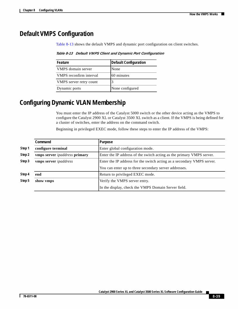
Chapter 8 Configuring VLANsHow the VMPS Works
S tofor
Default VMPS ConfigurationTable 8-13 shows the default VMPS and dynamic port configuration on client switches.
Configuring Dynamic VLAN MembershipYou must enter the IP address of the Catalyst 5000 switch or the other device acting as the VMPconfigure the Catalyst 2900 XL or Catalyst 3500 XL switch as a client. If the VMPS is being defineda cluster of switches, enter the address on the command switch.
Beginning in privileged EXEC mode, follow these steps to enter the IP address of the VMPS:
Table 8-13 Default VMPS Client and Dynamic Port Configuration
Feature Default Configuration
VMPS domain server None
VMPS reconfirm interval 60 minutes
VMPS server retry count 3
Dynamic ports None configured
Command Purpose
Step 1 configure terminal Enter global configuration mode.
Step 2 vmps serveripaddressprimary Enter the IP address of the switch acting as the primary VMPS server.
Step 3 vmps serveripaddress Enter the IP address for the switch acting as a secondary VMPS server.
You can enter up to three secondary server addresses.
Step 4 end Return to privileged EXEC mode.
Step 5 show vmps Verify the VMPS server entry.
In the display, check the VMPS Domain Server field.
8-39Catalyst 2900 Series XL and Catalyst 3500 Series XL Software Configuration Guide
78-6511-08
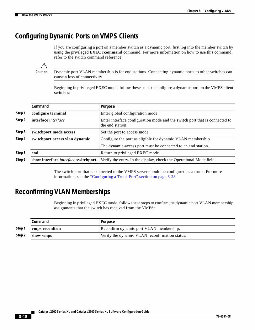
Chapter 8 Configuring VLANsHow the VMPS Works
h byd,
can
ient
hip
to
Configuring Dynamic Ports on VMPS ClientsIf you are configuring a port on a member switch as a dynamic port, first log into the member switcusing the privileged EXECrcommand command. For more information on how to use this commanrefer to the switch command reference.
Caution Dynamic port VLAN membership is for end stations. Connecting dynamic ports to other switchescause a loss of connectivity.
Beginning in privileged EXEC mode, follow these steps to configure a dynamic port on the VMPS clswitches:
The switch port that is connected to the VMPS server should be configured as a trunk. For moreinformation, see the“Configuring a Trunk Port” section on page 8-28.
Reconfirming VLAN MembershipsBeginning in privileged EXEC mode, follow these steps to confirm the dynamic port VLAN membersassignments that the switch has received from the VMPS:
Command Purpose
Step 1 configure terminal Enter global configuration mode.
Step 2 interface interface Enter interface configuration mode and the switch port that is connectedthe end station.
Step 3 switchport mode access Set the port to access mode.
Step 4 switchport access vlan dynamic Configure the port as eligible for dynamic VLAN membership.
The dynamic-access port must be connected to an end station.
Step 5 end Return to privileged EXEC mode.
Step 6 show interfaceinterfaceswitchport Verify the entry. In the display, check the Operational Mode field.
Command Purpose
Step 1 vmps reconfirm Reconfirm dynamic port VLAN membership.
Step 2 show vmps Verify the dynamic VLAN reconfirmation status.
8-40Catalyst 2900 Series XL and Catalyst 3500 Series XL Software Configuration Guide
78-6511-08
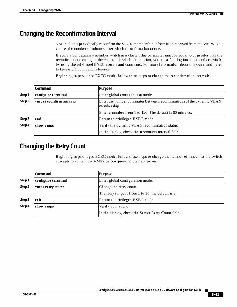
Chapter 8 Configuring VLANsHow the VMPS Works
ou
n theitcher
witch
N
Changing the Reconfirmation IntervalVMPS clients periodically reconfirm the VLAN membership information received from the VMPS. Ycan set the number of minutes after which reconfirmation occurs.
If you are configuring a member switch in a cluster, this parameter must be equal to or greater thareconfirmation setting on the command switch. In addition, you must first log into the member swby using the privileged EXECrcommand command. For more information about this command, refto the switch command reference.
Beginning in privileged EXEC mode, follow these steps to change the reconfirmation interval:
Changing the Retry CountBeginning in privileged EXEC mode, follow these steps to change the number of times that the sattempts to contact the VMPS before querying the next server:
Command Purpose
Step 1 configure terminal Enter global configuration mode.
Step 2 vmps reconfirm minutes Enter the number of minutes between reconfirmations of the dynamic VLAmembership.
Enter a number from 1 to 120. The default is 60 minutes.
Step 3 end Return to privileged EXEC mode.
Step 4 show vmps Verify the dynamic VLAN reconfirmation status.
In the display, check the Reconfirm Interval field.
Command Purpose
Step 1 configure terminal Enter global configuration mode.
Step 2 vmps retry count Change the retry count.
The retry range is from 1 to 10; the default is 3.
Step 3 exit Return to privileged EXEC mode.
Step 4 show vmps Verify your entry.
In the display, check the Server Retry Count field.
8-41Catalyst 2900 Series XL and Catalyst 3500 Series XL Software Configuration Guide
78-6511-08
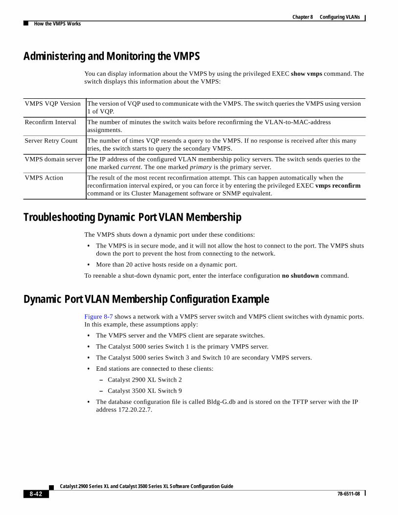
Chapter 8 Configuring VLANsHow the VMPS Works
uts
rts.
IP
sion
many
to the
Administering and Monitoring the VMPSYou can display information about the VMPS by using the privileged EXECshow vmpscommand. Theswitch displays this information about the VMPS:
Troubleshooting Dynamic Port VLAN MembershipThe VMPS shuts down a dynamic port under these conditions:
• The VMPS is in secure mode, and it will not allow the host to connect to the port. The VMPS shdown the port to prevent the host from connecting to the network.
• More than 20 active hosts reside on a dynamic port.
To reenable a shut-down dynamic port, enter the interface configurationno shutdown command.
Dynamic Port VLAN Membership Configuration ExampleFigure 8-7shows a network with a VMPS server switch and VMPS client switches with dynamic poIn this example, these assumptions apply:
• The VMPS server and the VMPS client are separate switches.
• The Catalyst 5000 series Switch 1 is the primary VMPS server.
• The Catalyst 5000 series Switch 3 and Switch 10 are secondary VMPS servers.
• End stations are connected to these clients:
– Catalyst 2900 XL Switch 2
– Catalyst 3500 XL Switch 9
• The database configuration file is called Bldg-G.db and is stored on the TFTP server with theaddress 172.20.22.7.
VMPS VQP Version The version of VQP used to communicate with the VMPS. The switch queries the VMPS using ver1 of VQP.
Reconfirm Interval The number of minutes the switch waits before reconfirming the VLAN-to-MAC-addressassignments.
Server Retry Count The number of times VQP resends a query to the VMPS. If no response is received after this tries, the switch starts to query the secondary VMPS.
VMPS domain server The IP address of the configured VLAN membership policy servers. The switch sends queriesone markedcurrent. The one markedprimary is the primary server.
VMPS Action The result of the most recent reconfirmation attempt. This can happen automatically when thereconfirmation interval expired, or you can force it by entering the privileged EXECvmps reconfirmcommand or its Cluster Management software or SNMP equivalent.
8-42Catalyst 2900 Series XL and Catalyst 3500 Series XL Software Configuration Guide
78-6511-08
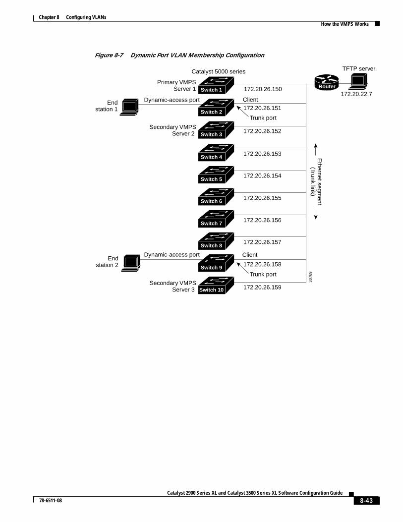
Chapter 8 Configuring VLANsHow the VMPS Works
Figure 8-7 Dynamic Port VLAN Membership Configuration
Primary VMPSServer 1
Secondary VMPSServer 2
Secondary VMPSServer 3
172.20.26.150
172.20.26.151
Trunk port
Catalyst 5000 series
172.20.26.152
Ethernet segm
ent(Trunk link)
172.20.26.153
172.20.26.154
172.20.26.155
172.20.26.156
172.20.26.157
172.20.26.158
172.20.26.159
Client
Client
Endstation 2
Endstation 1
TFTP server
Dynamic-access port
Dynamic-access port
Switch 10
Switch 9
Switch 8
Switch 7
Switch 6
Switch 5
Switch 3
Switch 2
Switch 1
Switch 4
172.20.22.7
3076
9Trunk port
Router
8-43Catalyst 2900 Series XL and Catalyst 3500 Series XL Software Configuration Guide
78-6511-08

Chapter 8 Configuring VLANsHow the VMPS Works
8-44Catalyst 2900 Series XL and Catalyst 3500 Series XL Software Configuration Guide
78-6511-08