Embed Size (px)
Citation preview
C H A P T E R
5-1Cisco Wide Area Application Services Configuration Guide
OL-24487-01
5Configuring Network Settings
This chapter describes how to configure basic network settings such as creating additional network interfaces to support network traffic, specifying a DNS server, enabling Cisco Discovery Protocol (CDP), and configuring the directed mode of operation where peer WAEs exchange traffic using UDP encapsulation to avoid firewall traversal issues.
Note Throughout this chapter, the term WAAS device is used to refer collectively to the WAAS Central Managers and WAEs in your network. The term WAE refers to WAE appliances, WAE Network Modules (the NME-WAE family of devices), and SM-SRE modules running WAAS.
This chapter contains the following sections:
• Configuring Network Interfaces, page 5-1
• Configuring TCP Settings, page 5-17
• Configuring Static IP Routes, page 5-20
• Configuring CDP Settings, page 5-21
• Configuring the DNS Server, page 5-22
• Configuring Windows Name Services, page 5-22
• Configuring Directed Mode, page 5-23
Configuring Network InterfacesDuring initial setup, you chose an initial interface and either configured it for DHCP or gave it a static IP address, as described in the Cisco Wide Area Application Services Quick Configuration Guide. This section describes how to configure additional interfaces using options for redundancy, load balancing, and performance optimization.
This section contains the following topics:
• Configuring a Standby Interface, page 5-2
• Assigning Physical Interfaces to the Standby Group, page 5-4
• Configuring Multiple IP Addresses on a Single Interface, page 5-5
• Modifying Gigabit or 10-Gigabit Ethernet Interface Settings, page 5-6
• Configuring Port-Channel Settings, page 5-8
• Configuring Interfaces for DHCP, page 5-11
5-2Cisco Wide Area Application Services Configuration Guide
OL-24487-01
Chapter 5 Configuring Network SettingsConfiguring Network Interfaces
• Modifying Virtual Interface Settings for a vWAAS Device, page 5-12
• Configuring Optimization on WAAS Express Interfaces, page 5-13
• Bridging to a Virtual Blade Interface, page 5-14
We recommend that you use the WAAS Central Manager GUI instead of the WAAS CLI to configure network settings, but if you want to use the CLI, see the following commands in the Cisco Wide Area Application Services Command Reference: interface, ip address, port-channel, and primary-interface.
Network interfaces are named as follows on WAAS devices:
• WAVE-274/474—Have one built-in Ethernet interface named GigabitEthernet 1/0.
• WAE-512/612/7326/674/7341/7371 and WAVE-574—Have two built-in Ethernet interfaces named GigabitEthernet 1/0 and GigabitEthernet 2/0.
• WAVE-294/594/694/7541/7571/8541—Have two built-in Ethernet interfaces named GigabitEthernet 0/0 and GigabitEthernet 0/1. Additional interfaces on the Cisco Interface Module are named GigabitEthernet 1/0 to 1/7, depending on the number of ports.
• NME devices—Have an internal interface to the router that is designated 1/0 and an external interface that is designated 2/0.
• SM-SRE devices—Have an internal interface to the router that is designated 1/0 and an external interface that is designated 2/0.
Note We strongly recommend that you do not use half-duplex connections on the WAE or on routers, switches, or other devices. Half duplex impedes performance and should not be used. Check each Cisco WAE interface and the port configuration on the adjacent device (router, switch, firewall, and WAE) to verify that full duplex is configured.
Configuring a Standby InterfaceIn this procedure, you configure a logical interface called a standby interface. After you configure this standby interface, you must associate physical interfaces with the standby interface to create the standby group. (A standby group consists of two physical interfaces.) In the WAAS Central Manager GUI, you create the standby group by assigning physical interfaces to the standby group and assigning one physical interface as primary. (See the “Assigning Physical Interfaces to the Standby Group” section on page 5-4.”)
Standby interfaces remain unused unless a member interface that is in use fails. When an in-use network interface fails (because of cable trouble, Layer 2 switch failure, or other failure), the other member interface of the standby group changes its state to in use and starts to carry traffic and take the load off the failed interface. With standby interface configuration, only one interface is in use at a given time.
To configure standby interfaces, you must assign two physical interface members to a standby group. The following operating considerations apply to standby groups:
• A standby group consists of two physical interfaces.
• The maximum number of standby groups on a WAAS device is two.
• A standby group is assigned a unique standby IP address, shared by all members of the group.
• Configuring the duplex and speed settings of the standby group member interfaces provides better reliability.
• IP ACLs can be configured on physical interfaces that are members of a standby group.
5-3Cisco Wide Area Application Services Configuration Guide
OL-24487-01
Chapter 5 Configuring Network SettingsConfiguring Network Interfaces
• One interface in a standby group is designated as the primary standby interface. Only the primary interface uses the group IP address.
• If the in-use interface fails, another interface in its standby group takes over and carries the traffic.
• If all the members of a standby group fail, then one recovers, the WAAS software brings up the standby group on the operational interface.
• The primary interface in a standby group can be changed at runtime. (The default action is to preempt the currently in-use interface if a different interface is made primary.)
• If a physical interface is a member of a standby group, it cannot also be a member of a port channel.
• If a device has only two interfaces, you cannot assign an IP address to both a standby group and a port channel. On such a device, only one virtual interface can be configured with an IP address.
• The member interfaces of a standby group can be connected to different switches if you use a VLAN tagging protocol and assign the same VLAN tag to each interface.
• You cannot include a built-in Ethernet port and a port on a Cisco Interface Module in the same standby group.
To configure a standby interface, follow these steps:
Step 1 From the WAAS Central Manager GUI navigation pane, choose My WAN > Manage Devices. The Devices window appears.
Step 2 Click the Edit icon next to the device for which you want to configure a standby interface. The Device Dashboard window appears.
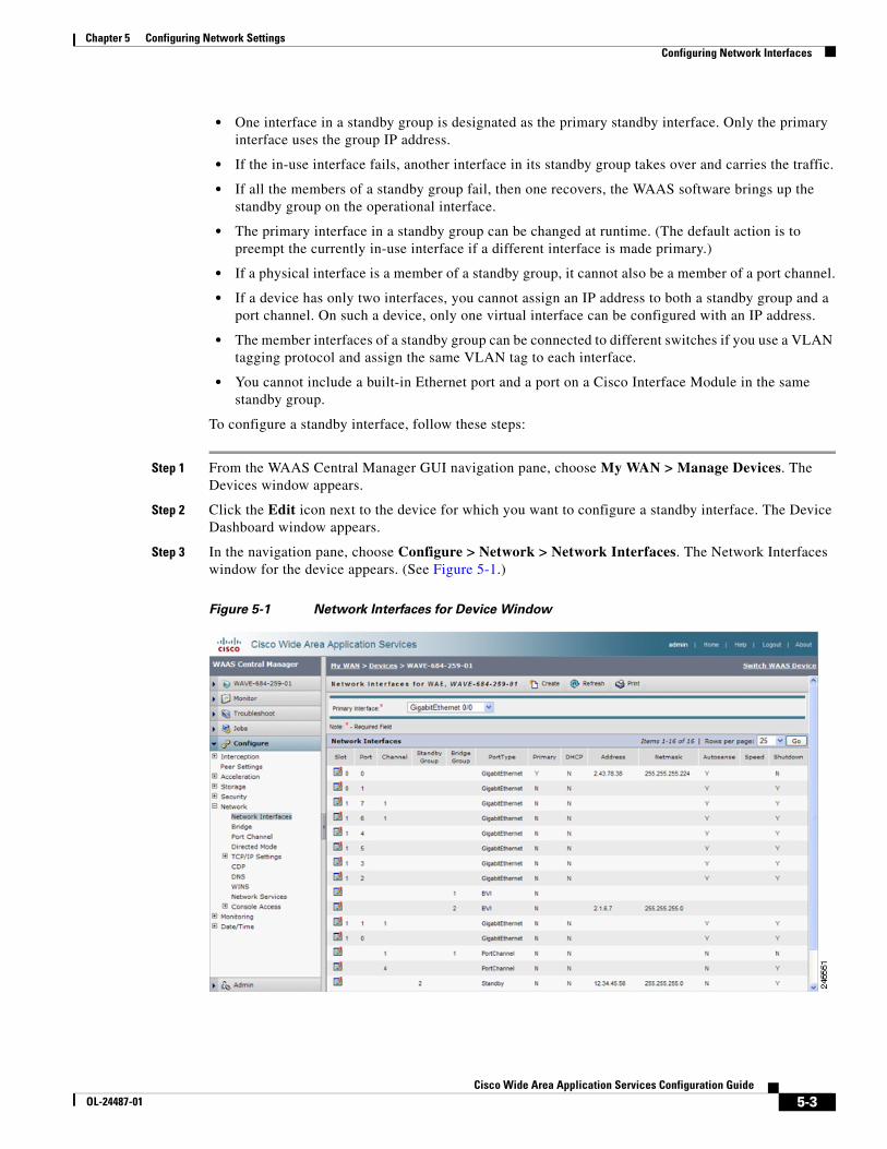
Step 3 In the navigation pane, choose Configure > Network > Network Interfaces. The Network Interfaces window for the device appears. (See Figure 5-1.)
Figure 5-1 Network Interfaces for Device Window
5-4Cisco Wide Area Application Services Configuration Guide
OL-24487-01
Chapter 5 Configuring Network SettingsConfiguring Network Interfaces
Step 4 In the taskbar, click the Create New Interface icon. The Creating New Network Interface window appears.
Step 5 From the Port Type drop-down list, choose Standby. The window refreshes with fields for configuring the standby group settings.
Step 6 From the Standby Group Number drop-down list, choose a group number for the interface.
Step 7 In the Description field, optionally enter a description for the standby group.
Step 8 In the Address field, specify the IP address of the standby group.
Step 9 In the Netmask field, specify the netmask of the standby group.
Step 10 Check the Shutdown check box to shut down the hardware interface. By default, this option is disabled.
Step 11 In the Gateway field enter the default gateway IP address. If an interface is configured for DHCP, then this field is read only.
Step 12 Click Submit.
Step 13 Configure the interface priority setting as described in the ““Assigning Physical Interfaces to the Standby Group” section on page 5-4.”
After you create the standby interface, you need to assign two physical interfaces to the standby group.
Assigning Physical Interfaces to the Standby Group
After you have configured a logical standby interface, you configure the standby group by assigning physical interfaces to the standby group and setting one physical interface as the primary standby interface. The primary interface in the standby group uses the standby group IP address. You must have a standby interface configured before you can set it as primary. (See the “Configuring a Standby Interface” section on page 5-2.”)
You can assign an interface to a standby group only if the interface does not have an IP address assigned. The interface uses the IP address of the standby group.
Note Removing a physical interface from standby group 2 on all WAAS device models can cause network disruption for up to 30 seconds. Additionally, removing a physical interface from standby group 1 on device models WAE-612/674/7341/7371 and WAVE-574 can cause network disruption for up to 30 seconds. The best practice is to make such changes when traffic interception is disabled or at an off-peak time when traffic disruption is acceptable.
To associate an interface with a standby group and set it as the primary standby interface, follow these steps:
Step 1 From the WAAS Central Manager GUI, choose My WAN > Manage Devices. The Devices window appears.
Step 2 Click the Edit icon next to the device for which you want to configure a standby interface. The Device Dashboard window appears.
Step 3 In the navigation pane, choose Configure > Network > Network Interfaces. The Network Interfaces window for the device appears.
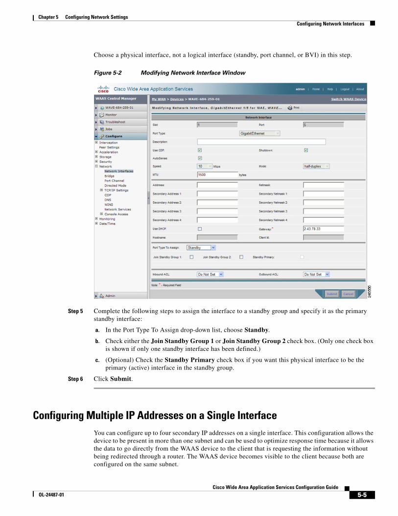
Step 4 Click the Edit icon next to the physical interface that you want to assign to a standby group. The Modifying Network Interface window appears. (See Figure 5-2.)
5-5Cisco Wide Area Application Services Configuration Guide
OL-24487-01
Chapter 5 Configuring Network SettingsConfiguring Network Interfaces
Choose a physical interface, not a logical interface (standby, port channel, or BVI) in this step.
Figure 5-2 Modifying Network Interface Window
Step 5 Complete the following steps to assign the interface to a standby group and specify it as the primary standby interface:
a. In the Port Type To Assign drop-down list, choose Standby.
b. Check either the Join Standby Group 1 or Join Standby Group 2 check box. (Only one check box is shown if only one standby interface has been defined.)
c. (Optional) Check the Standby Primary check box if you want this physical interface to be the primary (active) interface in the standby group.
Step 6 Click Submit.
Configuring Multiple IP Addresses on a Single InterfaceYou can configure up to four secondary IP addresses on a single interface. This configuration allows the device to be present in more than one subnet and can be used to optimize response time because it allows the data to go directly from the WAAS device to the client that is requesting the information without being redirected through a router. The WAAS device becomes visible to the client because both are configured on the same subnet.
5-6Cisco Wide Area Application Services Configuration Guide
OL-24487-01
Chapter 5 Configuring Network SettingsConfiguring Network Interfaces
To configure multiple IP addresses on a single interface, follow these steps:
Step 1 From the WAAS Central Manager GUI navigation pane, choose My WAN > Manage Devices. The Devices window appears.
Step 2 Click the Edit icon next to the device for which you want to configure interface settings. The Device Dashboard window appears.
Step 3 In the navigation pane, choose Configure > Network > Network Interfaces. The Network Interfaces listing window appears.
Step 4 Click the Edit icon for the physical interface that you want to modify. The Modifying Network Interface window appears.
Note Do not choose a standby or port-channel interface in this step. You cannot configure multiple IP addresses on these types of interfaces.
Step 5 In the Secondary Address and Secondary Netmask fields 1 through 4, enter up to four different IP addresses and secondary netmasks for the interface.
Step 6 Click Submit.
Modifying Gigabit or 10-Gigabit Ethernet Interface SettingsTo modify the settings of an existing 1-Gigabit or 10-Gigabit Ethernet interface, follow these steps:
Step 1 From the WAAS Central Manager GUI navigation pane, choose My WAN > Manage Devices.
The Devices window appears, listing all the device types configured in the WAAS network.
Step 2 Click the Edit icon next to the device for which you want to modify the interface settings.
The Device Dashboard window appears.
Step 3 In the navigation pane, choose Configure > Network > Network Interfaces.
The Network Interfaces window appears, listing the network interfaces configured on particular slots and ports.
Note On NME-WAE and SM-SRE devices, the internal interface to the router is designated slot 1, port 0 and the external interface is designated slot 2, port 0. For NME-WAE configuration details, see the document Configuring Cisco WAAS Network Modules for Cisco Access Routers. For SM-SRE configuration details, see the document Cisco SRE Service Module Configuration and Installation Guide.
Step 4 Click the Edit Network Interface icon next to the Gigabit or 10-Gigabit Ethernet interface that you want to modify.
The Modifying Network Interface window appears, displaying the interface configurations on a particular slot and port. (See Figure 5-2 on page 5-5.)
5-7Cisco Wide Area Application Services Configuration Guide
OL-24487-01
Chapter 5 Configuring Network SettingsConfiguring Network Interfaces
Note Some of the fields in the window are not available. Interface configurations for slot, port, and port type are set for physical interfaces during initial startup or by using the WAAS CLI.
Note When configuring the internal interface (GigabitEthernet 1/0) on an NME-WAE or SM-SRE device, you cannot change the following fields or check boxes: Port Channel Number, AutoSense, Speed, Mode, Address, Netmask, Use DHCP, and Standby Group. If you attempt to change these values, the Central Manager displays an error when you click Submit. These settings for the internal interface can be configured only through the host router CLI. For NME-WAE details, see the document Configuring Cisco WAAS Network Modules for Cisco Access Routers. For SM-SRE details, see the document Cisco SRE Service Module Configuration and Installation Guide.
Step 5 In the Description field, optionally enter a description for the interface.
Step 6 Check the Use CDP check box to enable Cisco Discovery Protocol (CDP) on an interface.
When enabled, CDP obtains protocol addresses of neighboring devices and discovers the platform of those devices. It also shows information about the interfaces used by your router.
Configuring CDP from the CDP Settings window enables CDP globally on all the interfaces. For information on configuring CDP settings, see the “Configuring CDP Settings” section on page 5-21.
Step 7 Check the Shutdown check box to shut down the hardware interface.
Step 8 Check the AutoSense check box to set the interface to autonegotiate the speed and mode. (This setting is not used on fiber 10-Gigabit Ethernet interfaces on a Cisco Interface Module.)
Checking this check box disables the manual Speed and Mode drop-down list settings.
Note When autosense is on, manual configurations are overridden. You must reboot the WAAS device to start autosensing.
Step 9 (Optional) Manually configure the interface transmission speed and mode settings as follows (these settings are not used on fiber 10-Gigabit Ethernet interfaces on a Cisco Interface Module):
a. Uncheck the AutoSense check box.
b. From the Speed drop-down list, choose a transmission speed (10, 100, or 1000 Mbps). You must choose 1000 Mbps for fiber Gigabit Ethernet interfaces on a Cisco Interface Module.
c. From the Mode drop-down list, choose a transmission mode (full-duplex or half-duplex). You must choose full-duplex for fiber Gigabit Ethernet interfaces on a Cisco Interface Module.
Full-duplex transmission allows data to travel in both directions at the same time through an interface or a cable. A half-duplex setting ensures that data only travels in one direction at any given time. Although full duplex is faster, the interfaces sometimes cannot operate effectively in this mode. If you encounter excessive collisions or network errors, you may configure the interface for half-duplex rather than full duplex.
Note We strongly recommend that you do not use half-duplex connections on the WAE or on routers, switches, or other devices. Half duplex impedes performance and should not be used. Check each Cisco WAE interface and the port configuration on the adjacent device (router, switch, firewall, and WAE) to verify that full duplex is configured.
5-8Cisco Wide Area Application Services Configuration Guide
OL-24487-01
Chapter 5 Configuring Network SettingsConfiguring Network Interfaces
Step 10 Specify a value (in bytes) in the MTU field to set the interface Maximum Transmission Unit (MTU) size.
The range is 576–1500 bytes. The MTU is the largest size of IP datagram that can be transferred using a specific data link connection.
Note The MTU field is not editable if the interface is assigned to a standby or port channel group.
Step 11 Enter a new IP address in the Address field to change the interface IP address.
Step 12 Enter a new netmask in the Netmask field to change the interface netmask.
Step 13 (Optional) From the Inbound ACL drop-down list, choose an IP ACL to apply to inbound packets.
The drop-down list contains all the IP ACLs that you configured in the system.
Step 14 (Optional) From the Outbound ACL drop-down list, choose an IP ACL to apply to outbound packets.
Step 15 Click Submit.
Note Changing the interface transmission speed, duplex mode, or MTU can cause network disruption for up to 30 seconds. The best practice is to make such changes when traffic interception is disabled or at an off-peak time when traffic disruption is acceptable.
Configuring Port-Channel SettingsWAAS software supports the grouping of up to four same-speed physical network interfaces into one logical interface called a port channel. After you configure this port-channel interface, you must associate physical interfaces with the port channel.
You can configure up to four port-channel interfaces. This capability also provides interoperability with Cisco routers, switches, and other networking devices or hosts supporting EtherChannel, load balancing, and automatic failure detection and recovery based on each interface’s current link status. EtherChannel is also referred to as a port channel.
You can use a port channel in a bridge group, as an interface bridged to a virtual blade. For more information on configuring a bridge, see the “Bridging to a Virtual Blade Interface” section on page 5-14.
The following operating considerations apply to a port-channel virtual interface:
• A physical interface can be a member of a port channel or a standby group, but not both.
• You cannot assign an IP address to both a port channel and a standby group. Only one virtual interface can be configured with an IP address.
• All port-channel member interfaces must have the same port bandwidth.
• Port-channel settings are not applicable to vWAAS devices.
Note You must disable autoregistration if the device has only two interfaces and both device interfaces are configured as port-channel interfaces.
To configure a port-channel interface, follow these steps:
5-9Cisco Wide Area Application Services Configuration Guide
OL-24487-01
Chapter 5 Configuring Network SettingsConfiguring Network Interfaces
Step 1 From the WAAS Central Manager GUI navigation pane, choose My WAN > Manage Devices. The Devices window appears.
Step 2 Click the Edit icon next to the name of the device for which you want to configure interfaces. The Device Dashboard window appears.
Step 3 In the navigation Pane, choose Configure > Network > Network Interfaces. The Network Interfaces window appears, listing all the interfaces for the chosen device.
Step 4 In the taskbar, click the Create New Interface icon. The Creating New Network Interface window appears.
Step 5 From the Port Type drop-down list, choose PortChannel.
The window refreshes and provides fields for configuring the network interface settings.
Step 6 In the Port Channel Number drop-down list, choose the number of the port-channel interface. Up to four port channels are supported, depending on the WAAS device model and installed interface module.
Step 7 (Optional) In the Bridge Group Number drop-down list, choose the number of the bridge group to which you want to assign this port-channel interface, if you want to bridge to a virtual blade.
Step 8 In the Description field, optionally enter a description for the port channel.
Step 9 Check the Shutdown check box to shut down this interface. By default, this option is disabled.
Step 10 In the Gateway field, enter the default gateway IP address.
Step 11 In the Address field, specify the IP address of the interface.
Step 12 In the Netmask field, specify the netmask of the interface.
Step 13 (Optional) From the Inbound ACL drop-down list, choose an IP ACL to apply to inbound packets.
The drop-down list contains all the IP ACLs that you configured in the system.
Step 14 (Optional) From the Outbound ACL drop-down list, choose an IP ACL to apply to outbound packets.
Step 15 Click Submit.
After you create the port-channel interface, you need to assign physical interfaces to the port channel.
Assigning Physical Interfaces to a Port Channel
After you have configured a logical port-channel interface, you must assign multiple physical interfaces to the port channel. You can assign up to four physical interfaces to one port-channel interface, depending on the WAAS device.
You can assign an interface to a port channel only if the interface does not have an IP address assigned. The interface uses the IP address of the port channel.
You cannot combine built-in Ethernet ports with ports on a Cisco Interface Module into the same port channel interface.
Note Removing a physical interface from a port channel on device models WAE-612/674/7341/7371 and WAVE-574 can cause network disruption for up to 30 seconds. The best practice is to make such changes when traffic interception is disabled or at an off-peak time when traffic disruption is acceptable.
5-10Cisco Wide Area Application Services Configuration Guide
OL-24487-01
Chapter 5 Configuring Network SettingsConfiguring Network Interfaces
To add an interface to a port channel, follow these steps:
Step 1 From the WAAS Central Manager GUI, choose My WAN > Manage Devices. The Devices window appears.
Step 2 Click the Edit icon next to the device for which you want to configure a port channel interface. The Device Dashboard window appears.
Step 3 In the navigation pane, choose Configure > Network > Network Interfaces. The Network Interfaces window for the device appears.
Step 4 Click the Edit icon next to the physical interface that you want to assign to a port channel. The Modifying Network Interface window appears. (See Figure 5-2.)
Choose a physical interface, not a logical interface (standby, port channel, or BVI) in this step.
Step 5 Complete the following steps to assign the interface to a port channel:
a. In the Port Type To Assign drop-down list, choose PortChannel.
b. In the Port Channel Number drop-down list, choose the number of the port channel to which you want to add the physical interface.
Step 6 Click Submit.
Configuring a Load-Balancing Method for Port-Channel Interfaces
Before you configure load balancing, ensure that you have configured the port-channel settings described in the “Configuring Port-Channel Settings” section on page 5-8.
To configure load balancing, follow these steps:
Step 1 From the WAAS Central Manager GUI navigation pane, choose My WAN > Manage Devices (or Manage Device Groups).
Step 2 Click the Edit icon next to the device or device group with the port channel that you want to configure for load balancing.
Step 3 In the navigation Pane, choose Configure > Network > Port Channel.
Step 4 From the Load Balancing Method drop-down list, choose a load-balancing method:
• src-dst-ip-port—The distribution function is based on a combination of source and destination IP addresses/ports. This load-balancing method is the only method available on devices running version 4.4.1 and later.
• round-robin—Round robin allows traffic to be distributed evenly among all interfaces in the channel group. This load-balancing method is available only on devices running versions prior to 4.4.1.
Step 5 Click Submit.
To configure a load-balancing method from the CLI, you can use the port-channel global configuration command.
5-11Cisco Wide Area Application Services Configuration Guide
OL-24487-01
Chapter 5 Configuring Network SettingsConfiguring Network Interfaces
Note A device group may be configured with a load-balancing method supported only by previous WAAS software versions to configure devices running previous versions. When viewing the Port Channel Settings page for a version 4.4.1 or later device that gets its settings from such a device group, you may see an unsupported load-balancing method listed. However, a version 4.4.1 or later device supports only the src-dst-ip-port load-balancing method and this is the method actually configured on the device, regardless of what the device group or device configuration window shows for the setting.
Configuring Interfaces for DHCP
Note You must disable autoregistration before you can manually configure an interface for DHCP.
A WAAS device sends its configured client identifier and hostname to the DHCP server when requesting network information. You can configure DHCP servers to identify the client identifier information and the hostname information that the WAAS device is sending and then to send back the specific network settings that are assigned to the WAAS device.
To enable an interface for DHCP, follow these steps:
Step 1 From the WAAS Central Manager GUI navigation pane, choose My WAN > Manage Devices. The Devices window appears.
Step 2 Click the Edit icon next to the name of the device for which you want to configure interface settings. The Device Dashboard window appears.
Step 3 In the navigation pane, choose Configure > Network > Network Interfaces. The Network Interfaces listing window appears.
Step 4 Click the Edit icon for the physical interface that you want to modify. The Modifying Network Interface window appears.
Note Do not choose a logical interface (standby, port channel, or BVI) in this step, because you cannot configure DHCP on a logical interface. In addition, do not choose the internal interface (GigabitEthernet 1/0) on an NME-WAE or SM-SRE module, because this interface can be configured only through the host router CLI. For NME-WAE details, see the document Configuring Cisco WAAS Network Modules for Cisco Access Routers. For SM-SRE details, see the document Cisco SRE Service Module Configuration and Installation Guide.
Step 5 Scroll down the window and check the Use DHCP check box.
When this check box is checked, the secondary IP address and netmask fields are disabled.
Step 6 In the Hostname field, specify the hostname for the WAAS device or other device.
Step 7 In the Client Id field, specify the configured client identifier for the device.
The DHCP server uses this identifier when the WAAS device requests the network information for the device.
Step 8 Click Submit.
5-12Cisco Wide Area Application Services Configuration Guide
OL-24487-01
Chapter 5 Configuring Network SettingsConfiguring Network Interfaces
Modifying Virtual Interface Settings for a vWAAS DeviceTo modify the settings of an existing vWAAS interface, follow these steps:
Step 1 From the WAAS Central Manager GUI navigation pane, choose My WAN > Manage Devices.
The Devices window appears, listing all the device types configured in the WAAS network.
Step 2 Click the Edit icon next to the device for which you want to modify the interface settings.
The Device Dashboard window appears.
Step 3 In the navigation pane, choose Configure > Network > Network Interfaces.
The Network Interfaces window appears, listing the network interfaces configured on particular slots and ports.
Note Certain values (including autosense) are not applicable to a vWAAS interface.
Step 4 Click the Edit Network Interface icon next to the virtual interface that you want to modify.
The Modifying Network Interface window appears, displaying the interface configurations on a particular slot and port. (See Figure 5-2 on page 5-5.)
Note Interface configurations for slot, port, and port type are set for virtual interfaces during initial startup or by using the WAAS CLI.
Some of the fields in the window (port channel number, autosense, speed, mode, and standby-related fields) are not available because they are not applicable.
Step 5 Check the Use CDP check box to enable Cisco Discovery Protocol (CDP) on an interface.
When enabled, CDP obtains protocol addresses of neighboring devices and discovers the platform of those devices. It also shows information about the interfaces used by your router.
Configuring CDP from the CDP Settings window enables CDP globally on all the interfaces. For information on configuring CDP settings, see the “Configuring CDP Settings” section on page 5-21.
Step 6 Check the Shutdown check box to shut down the virtual interface.
Step 7 Specify a value (in bytes) in the MTU field to set the interface Maximum Transmission Unit (MTU) size.
The range is 576–1500 bytes. The MTU is the largest size of IP datagram that can be transferred using a specific data link connection.
Step 8 Enter a new IP address in the Address field to change the interface IP address.
Step 9 Enter a new netmask in the Netmask field to change the interface netmask.
Step 10 Scroll down the window and check the Use DHCP check box.
Step 11 In the Gateway’s IP Address field, enter the IP address of the gateway interface.
The gateway interface IP address should be in the same network as that of one of the device’s network interfaces.
Step 12 In the Hostname field, specify the hostname for the WAAS device or other device.
Step 13 In the Client Id field, specify the configured client identifier for the device.
5-13Cisco Wide Area Application Services Configuration Guide
OL-24487-01
Chapter 5 Configuring Network SettingsConfiguring Network Interfaces
The DHCP server uses this identifier when the WAAS device requests the network information for the device.
Step 14 (Optional) From the Inbound ACL drop-down list, choose an IP ACL to apply to inbound packets.
The drop-down list contains all the IP ACLs that you configured in the system.
Step 15 (Optional) From the Outbound ACL drop-down list, choose an IP ACL to apply to outbound packets.
Step 16 Click Submit.
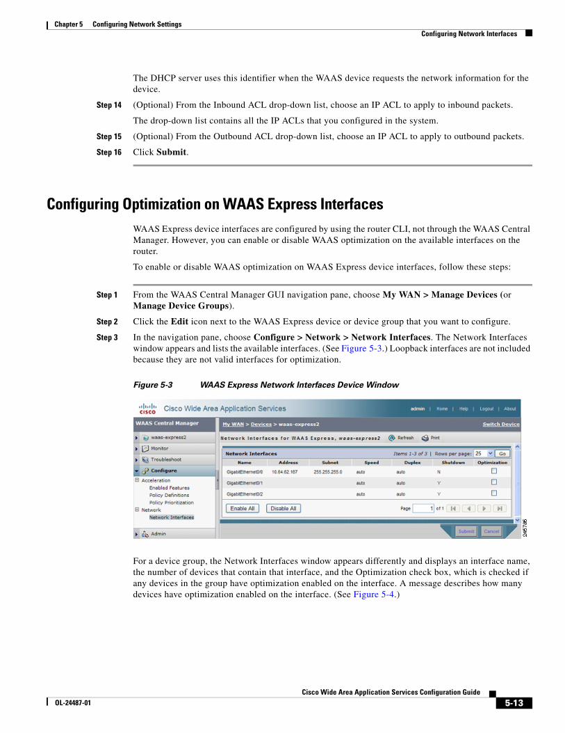
Configuring Optimization on WAAS Express InterfacesWAAS Express device interfaces are configured by using the router CLI, not through the WAAS Central Manager. However, you can enable or disable WAAS optimization on the available interfaces on the router.
To enable or disable WAAS optimization on WAAS Express device interfaces, follow these steps:
Step 1 From the WAAS Central Manager GUI navigation pane, choose My WAN > Manage Devices (or Manage Device Groups).
Step 2 Click the Edit icon next to the WAAS Express device or device group that you want to configure.
Step 3 In the navigation pane, choose Configure > Network > Network Interfaces. The Network Interfaces window appears and lists the available interfaces. (See Figure 5-3.) Loopback interfaces are not included because they are not valid interfaces for optimization.
Figure 5-3 WAAS Express Network Interfaces Device Window
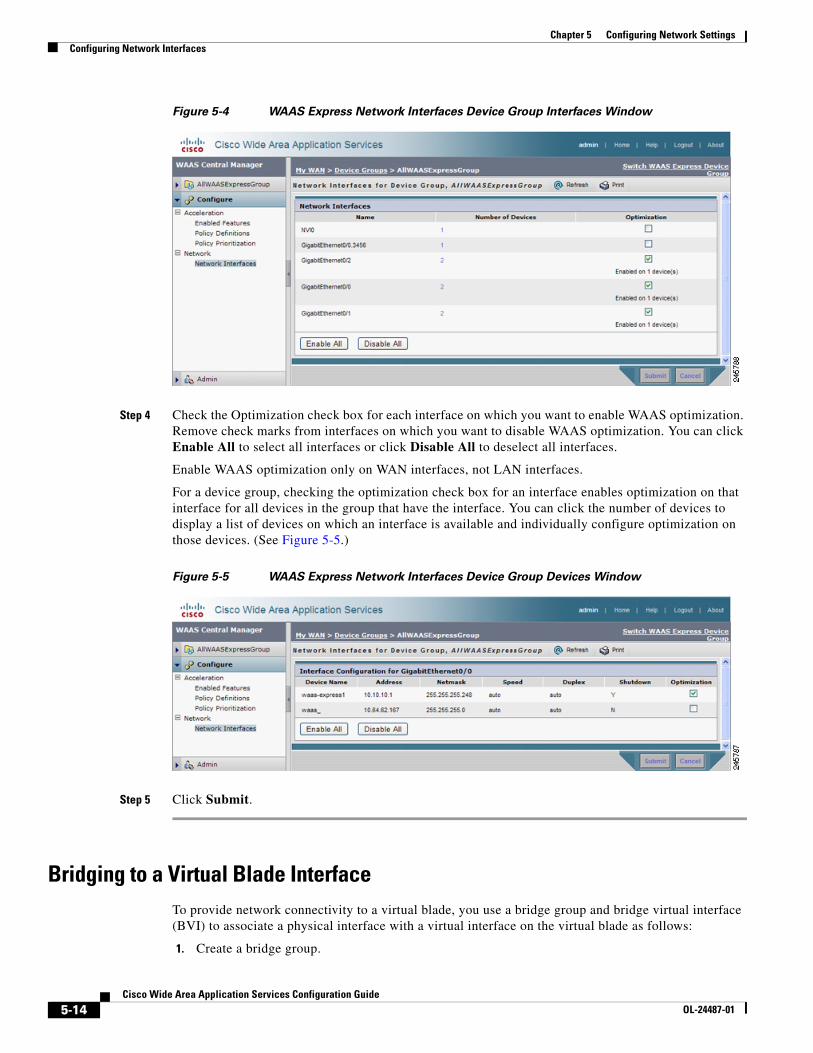
For a device group, the Network Interfaces window appears differently and displays an interface name, the number of devices that contain that interface, and the Optimization check box, which is checked if any devices in the group have optimization enabled on the interface. A message describes how many devices have optimization enabled on the interface. (See Figure 5-4.)
5-14Cisco Wide Area Application Services Configuration Guide
OL-24487-01
Chapter 5 Configuring Network SettingsConfiguring Network Interfaces
Figure 5-4 WAAS Express Network Interfaces Device Group Interfaces Window
Step 4 Check the Optimization check box for each interface on which you want to enable WAAS optimization. Remove check marks from interfaces on which you want to disable WAAS optimization. You can click Enable All to select all interfaces or click Disable All to deselect all interfaces.
Enable WAAS optimization only on WAN interfaces, not LAN interfaces.
For a device group, checking the optimization check box for an interface enables optimization on that interface for all devices in the group that have the interface. You can click the number of devices to display a list of devices on which an interface is available and individually configure optimization on those devices. (See Figure 5-5.)
Figure 5-5 WAAS Express Network Interfaces Device Group Devices Window
Step 5 Click Submit.
Bridging to a Virtual Blade InterfaceTo provide network connectivity to a virtual blade, you use a bridge group and bridge virtual interface (BVI) to associate a physical interface with a virtual interface on the virtual blade as follows:
1. Create a bridge group.
5-15Cisco Wide Area Application Services Configuration Guide
OL-24487-01
Chapter 5 Configuring Network SettingsConfiguring Network Interfaces
2. Create a bridge virtual interface in the bridge group.
3. Assign one physical, port-channel, or standby interface to the bridge group.
4. Assign the virtual blade interface to the bridge group.
These steps are described in more detail in this section.
Bridge interfaces are supported only on WAAS devices that support virtual blades.
You can create up to four bridge interfaces on a device, depending on the device model.
To create a bridge group, follow these steps:
Step 1 From the WAAS Central Manager GUI navigation pane, choose My WAN > Manage Devices.
The Devices window appears, listing all the device types configured in the WAAS network.
Step 2 Click the Edit icon next to the device for which you want to modify the interface settings.
The Device Dashboard window appears.
Step 3 In the navigation pane, choose Configure > Network > Bridge.
The Bridge Settings window appears, listing the bridge interfaces configured.
From the Bridge Settings window, you can perform the following tasks:
• Delete an existing bridge interface by clicking the Edit icon next to the interface number. You can then delete the bridge interface by clicking the Delete taskbar icon.
• Add a new bridge interface, as described in the following steps.
Step 4 Click the Create Bridge Interface taskbar icon to create a bridge interface.
The Creating new Bridge window appears.
Step 5 From the Bridge Index drop-down list, choose the number of the bridge interface (1–4).
The only supported Protocol is ieee.
Step 6 Click Submit.
To create a bridge group from the CLI, you can use the bridge global configuration command.
After you create the bridge group, you must create a bridge virtual interface associated with the bridge group.
To create the bridge virtual interface, follow these steps:
Step 1 From the WAAS Central Manager GUI navigation pane, choose My WAN > Manage Devices. The Devices window appears.
Step 2 Click the Edit icon next to the name of the device for which you want to configure interfaces. The Device Dashboard window appears.
Step 3 In the navigation Pane, choose Configure > Network > Network Interfaces. The Network Interfaces window appears, listing all the interfaces for the chosen device.
Step 4 In the taskbar, click the Create New Interface icon. The Creating New Network Interface window appears.
Step 5 From the Port Type drop-down list, choose BVI.
The window refreshes and provides fields for configuring the network interface settings.
5-16Cisco Wide Area Application Services Configuration Guide
OL-24487-01
Chapter 5 Configuring Network SettingsConfiguring Network Interfaces
Step 6 In the Bridge Group Number drop-down list, choose the number of the bridge group for this interface. Up to four bridge groups are supported, depending on the WAAS device model.
Step 7 In the Description field, optionally enter a description for the bridge virtual interface.
Step 8 Check the Shutdown check box to shut down this interface. By default, this option is disabled.
Step 9 In the Gateway field, enter the default gateway IP address.
Step 10 In the Address field, specify the IP address of the interface.
Step 11 In the Netmask field, specify the netmask of the interface.
Step 12 In the Secondary Address and Secondary Netmask fields 1 through 4, enter up to four different IP addresses and secondary netmasks for the interface.
Step 13 Click Submit.
To create a bridge virtual interface from the CLI, you can use the interface bvi global configuration command.
After you create the bridge virtual interface, you must assign a physical, port-channel, or standby interface to the bridge group.
To assign an interface to the bridge group, follow these steps:
Step 1 From the WAAS Central Manager GUI navigation pane, choose My WAN > Manage Devices. The Devices window appears.
Step 2 Click the Edit icon next to the name of the device for which you want to configure interfaces. The Device Dashboard window appears.
Step 3 In the navigation Pane, choose Configure > Network > Network Interfaces. The Network Interfaces window appears, listing all the interfaces for the chosen device.
Step 4 Click the Edit icon next to the physical, port-channel, or standby interface that you want to assign to the bridge group.
Do not choose a primary interface because a primary interface cannot be assigned to a bridge group.
Step 5 In the Description field, optionally enter a description for the interface.
Step 6 Leave the Address and Netmask fields empty.
Step 7 If the interface is a physical interface, in the Port Type To Assign drop-down list, choose Bridge Group.
Step 8 In the Bridge Group Number drop-down list, choose the bridge group to which to assign the interface.
Step 9 Click Submit.
To assign a physical, port-channel, or standby interface to the bridge group from the CLI, you can use the interface GigabitEthernet, interface TenGigabitEthernet, interface portchannel, or interface standby global configuration commands, with the bridge-group keyword.
After you assign a physical or port-channel interface to the bridge group, you must assign a virtual blade interface to the bridge group. For details, see the “Configuring Virtual Blades” section on page 13-4.
5-17Cisco Wide Area Application Services Configuration Guide
OL-24487-01
Chapter 5 Configuring Network SettingsConfiguring TCP Settings
Configuring TCP SettingsFor data transactions and queries between client and servers, the size of windows and buffers is important, so fine-tuning the TCP stack parameters becomes the key to maximizing cache performance.
Because of the complexities involved in TCP parameters, be careful in tuning these parameters. In nearly all environments, the default TCP settings are adequate. Fine tuning of TCP settings is for network administrators with adequate experience and full understanding of TCP operation details.
To configure TCP and IP settings, follow these steps:
Step 1 From the WAAS Central Manager GUI navigation pane, choose My WAN > Manage Devices (or Manage Device Groups).
Step 2 Click the Edit icon next to the WAAS device or device group for which you want to configure TCP settings. The Device Dashboard window appears.
Step 3 In the navigation pane, choose Configure > Network > TCP/IP Settings > TCP/IP. The TCP/IP Settings window appears.
Step 4 Make the necessary changes to the TCP settings.
See Table 5-1 for a description of each TCP field in this window.
Step 5 Click Submit.
A “Click Submit to Save” message appears in red next to the Current Settings line when there are pending changes to be saved after you have applied default or device group settings. You can also revert to the previously configured settings by clicking Reset. The Reset button is visible only when you have applied default or group settings to change the current device settings but have not yet submitted the changes.
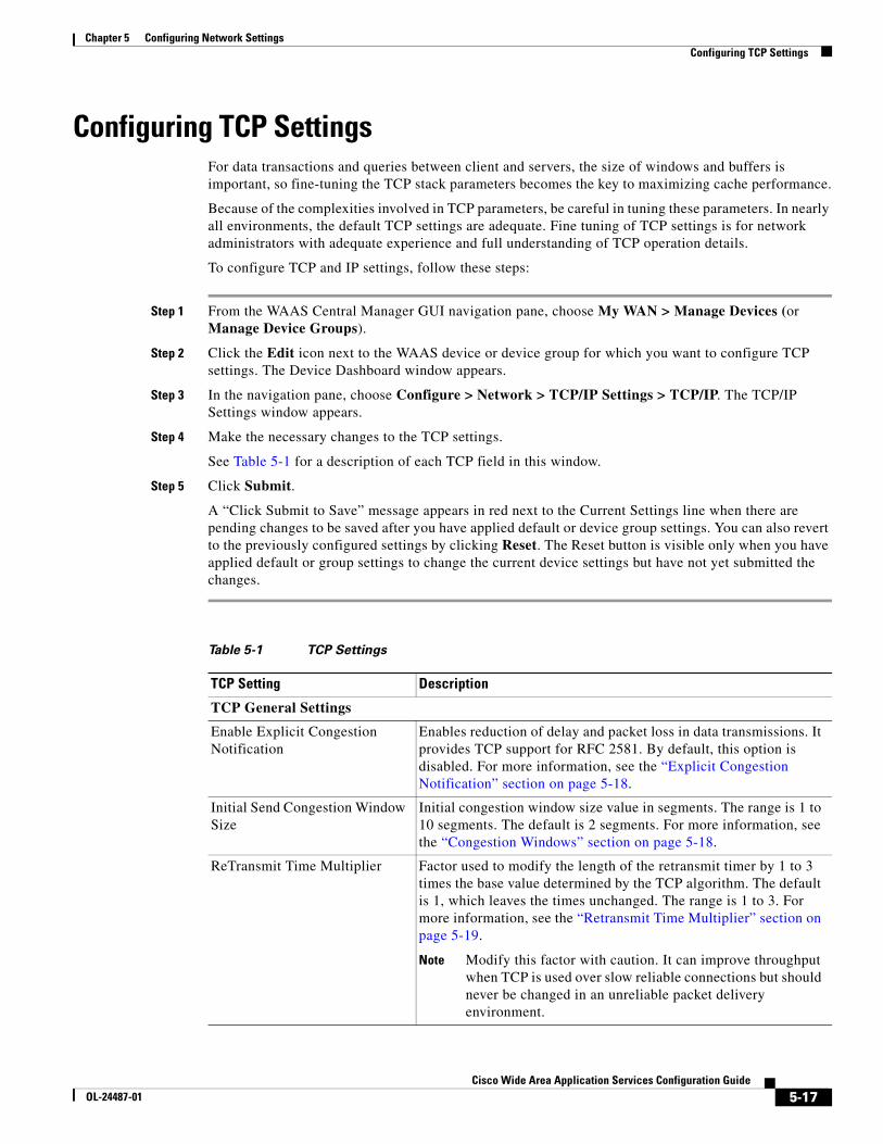
Table 5-1 TCP Settings
TCP Setting Description
TCP General Settings
Enable Explicit Congestion Notification
Enables reduction of delay and packet loss in data transmissions. It provides TCP support for RFC 2581. By default, this option is disabled. For more information, see the “Explicit Congestion Notification” section on page 5-18.
Initial Send Congestion Window Size
Initial congestion window size value in segments. The range is 1 to 10 segments. The default is 2 segments. For more information, see the “Congestion Windows” section on page 5-18.
ReTransmit Time Multiplier Factor used to modify the length of the retransmit timer by 1 to 3 times the base value determined by the TCP algorithm. The default is 1, which leaves the times unchanged. The range is 1 to 3. For more information, see the “Retransmit Time Multiplier” section on page 5-19.
Note Modify this factor with caution. It can improve throughput when TCP is used over slow reliable connections but should never be changed in an unreliable packet delivery environment.
5-18Cisco Wide Area Application Services Configuration Guide
OL-24487-01
Chapter 5 Configuring Network SettingsConfiguring TCP Settings
To configure TCP settings from the CLI, you can use the tcp global configuration command.
To enable the MTU discovery utility from the CLI, you can use the ip path-mtu-discovery enable global configuration command.
This section contains the following topics:
• Explicit Congestion Notification, page 5-18
• Congestion Windows, page 5-18
• Retransmit Time Multiplier, page 5-19
• TCP Slow Start, page 5-19
• Path MTU Discovery, page 5-20
Explicit Congestion NotificationThe TCP Explicit Congestion Notification (ECN) feature allows an intermediate router to notify the end hosts of impending network congestion. It also provides enhanced support for TCP sessions associated with applications that are sensitive to delay or packet loss. The major issue with ECN is that the operation of both the routers and the TCP software stacks needs to be changed to accommodate the operation of ECN.
Congestion WindowsThe congestion window (cwnd) is a TCP state variable that limits the amount of data that a TCP sender can transmit onto the network before receiving an acknowledgment (ACK) from the receiving side of the TCP transmission. The TCP cwnd variable is implemented by the TCP congestion avoidance algorithm. The goal of the congestion avoidance algorithm is to continually modify the sending rate so that the sender automatically senses any increase or decrease in available network capacity during the entire data flow. When congestion occurs (manifested as packet loss), the sending rate is first lowered then gradually increased as the sender continues to probe the network for additional capacity.
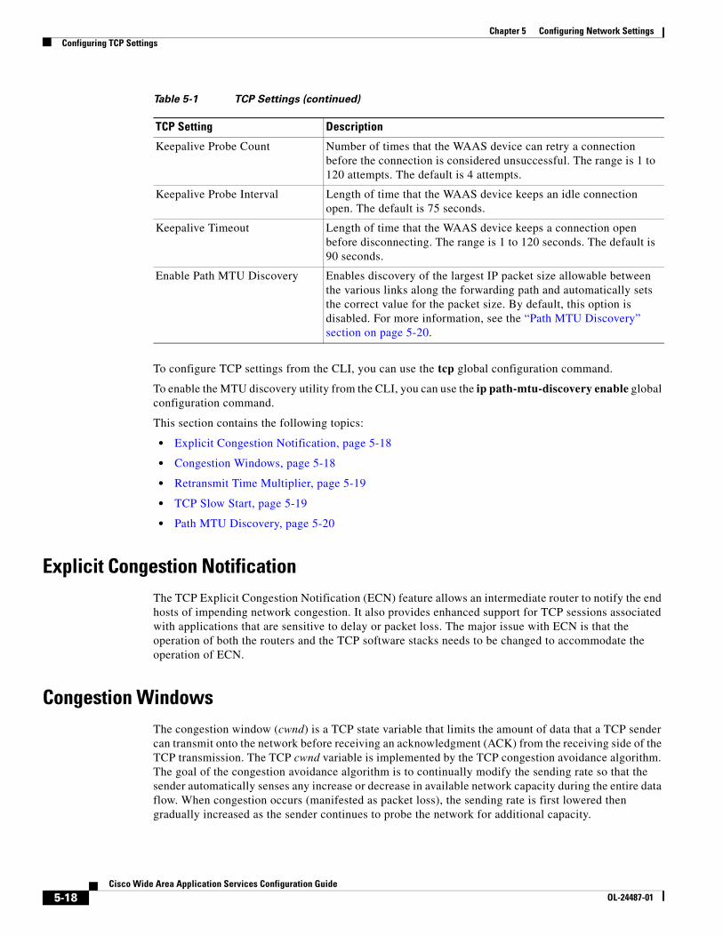
Keepalive Probe Count Number of times that the WAAS device can retry a connection before the connection is considered unsuccessful. The range is 1 to 120 attempts. The default is 4 attempts.
Keepalive Probe Interval Length of time that the WAAS device keeps an idle connection open. The default is 75 seconds.
Keepalive Timeout Length of time that the WAAS device keeps a connection open before disconnecting. The range is 1 to 120 seconds. The default is 90 seconds.
Enable Path MTU Discovery Enables discovery of the largest IP packet size allowable between the various links along the forwarding path and automatically sets the correct value for the packet size. By default, this option is disabled. For more information, see the “Path MTU Discovery” section on page 5-20.
Table 5-1 TCP Settings (continued)
TCP Setting Description
5-19Cisco Wide Area Application Services Configuration Guide
OL-24487-01
Chapter 5 Configuring Network SettingsConfiguring TCP Settings
Retransmit Time MultiplierThe TCP sender uses a timer to measure the time that has elapsed between sending a data segment and receiving the corresponding ACK from the receiving side of the TCP transmission. When this retransmit timer expires, the sender (according to the RFC standards for TCP congestion control) must reduce its sending rate. However, because the sender is not reducing its sending rate in response to network congestion, the sender is not able to make any valid assumptions about the current state of the network. Therefore, in order to avoid congesting the network with an inappropriately large burst of data, the sender implements the slow start algorithm, which reduces the sending rate to one segment per transmission. (See the ““TCP Slow Start” section on page 5-19.”)
You can modify the sender’s retransmit timer by using the Retransmit Time Multiplier field in the WAAS Central Manager GUI. The retransmit time multiplier modifies the length of the retransmit timer by one to three times the base value, as determined by the TCP algorithm that is being used for congestion control.
When making adjustments to the retransmit timer, be aware that they affect performance and efficiency. If the retransmit timer is triggered too early, the sender pushes duplicate data onto the network unnecessarily; if the timer is triggered too slowly, the sender remains idle for too long, unnecessarily slowing data flow.
TCP Slow StartSlow start is one of four congestion control algorithms used by TCP. The slow start algorithm controls the amount of data being inserted into the network at the beginning of a TCP session when the capacity of the network is not known.
For example, if a TCP session began by inserting a large amount of data into the network, much of the initial burst of data would likely be lost. Instead, TCP initially transmits a modest amount of data that has a high probability of successful transmission. Next, TCP probes the network by sending increasing amounts of data as long as the network does not show signs of congestion.
The slow start algorithm begins by sending packets at a rate that is determined by the congestion window, or cwnd variable. (See the ““Congestion Windows” section on page 5-18.”) The algorithm continues to increase the sending rate until it reaches the limit set by the slow start threshold (ssthresh) variable. Initially, the value of the ssthresh variable is adjusted to the receiver’s maximum segment size (RMSS). However, when congestion occurs, the ssthresh variable is set to half the current value of the cwnd variable, marking the point of the onset of network congestion for future reference.
The starting value of the cwnd variable is set to that of the sender maximum segment size (SMSS), which is the size of the largest segment that the sender can transmit. The sender sends a single data segment, and because the congestion window is equal to the size of one segment, the congestion window is now full. The sender then waits for the corresponding ACK from the receiving side of the transmission. When the ACK is received, the sender increases its congestion window size by increasing the value of the cwnd variable by the value of one SMSS. Now the sender can transmit two segments before the congestion window is again full and the sender is once more required to wait for the corresponding ACKs for these segments. The slow start algorithm continues to increase the value of the cwnd variable and therefore increase the size of the congestion window by one SMSS for every ACK received. If the value of the cwnd variable increases beyond the value of the ssthresh variable, then the TCP flow control algorithm changes from the slow start algorithm to the congestion avoidance algorithm.
5-20Cisco Wide Area Application Services Configuration Guide
OL-24487-01
Chapter 5 Configuring Network SettingsConfiguring Static IP Routes
Path MTU DiscoveryThe WAAS software supports the IP Path Maximum Transmission Unit (MTU) Discovery method, as defined in RFC 1191. When enabled, the Path MTU Discovery feature discovers the largest IP packet size allowable between the various links along the forwarding path and automatically sets the correct value for the packet size. By using the largest MTU that the links can handle, the sending device can minimize the number of packets it must send.
IP Path MTU Discovery is useful when a link in a network goes down, which forces the use of another, different MTU-sized link. IP Path MTU Discovery is also useful when a connection is first being established, and the sender has no information about the intervening links.
Note IP Path MTU Discovery is a process initiated by the sending device. If a server does not support IP Path MTU Discovery, the receiving device will have no available means to avoid fragmenting datagrams generated by the server.
By default, this feature is disabled. With the feature disabled, the sending device uses a packet size that is the lesser of 576 bytes and the next hop MTU. Existing connections are not affected when this feature is turned on or off.
Configuring Static IP RoutesThe WAAS software allows you to configure a static route for a network or host. Any IP packet designated for the specified destination uses the configured route.
To configure a static IP route, follow these steps:
Step 1 From the WAAS Central Manager GUI navigation pane, choose My WAN > Manage Devices (or Manage Devices Group).
Step 2 Click the Edit icon next to the device or device group that you want to configure.
Step 3 In the navigation pane, choose Configure > Network > TCP/IP Settings > Static Routes. The IP Route Entries window appears.
Step 4 In the taskbar, click the Create New IP Route Entry icon. The Creating New IP Route window appears.
Step 5 In the Destination Network Address field, enter the destination network IP address.
Step 6 In the Netmask field, enter the destination host netmask.
Step 7 In the Gateway’s IP Address field, enter the IP address of the gateway interface.
The gateway interface IP address should be in the same network as that of one of the device’s network interfaces.
Step 8 Click Submit.
To configure a static route from the CLI, you can use the ip route global configuration command.
5-21Cisco Wide Area Application Services Configuration Guide
OL-24487-01
Chapter 5 Configuring Network SettingsConfiguring CDP Settings
Aggregating IP RoutesAn individual WAE device can have IP routes defined and can belong to device groups that have other IP routes defined.
In the IP Route Entries window, the Aggregate Settings radio button controls how IP routes are aggregated for an individual device, as follows:
• Choose Yes if you want to configure the device with all IP routes that are defined for itself and for device groups to which it belongs.
• Choose No if you want to limit the device to just the IP routes that are defined for itself.
When you change the setting, you get the following confirmation message: “This option will take effect immediately and will affect the device configuration. Do you wish to continue?” Click OK to continue.
Configuring CDP SettingsCisco Discovery Protocol (CDP) is a device discovery protocol that runs on all Cisco-manufactured devices. With CDP, each device in a network sends periodic messages to all other devices in the network. All devices listen to periodic messages that are sent by others to learn about neighboring devices and determine the status of their interfaces.
With CDP, network management applications can learn the device type and the Simple Network Management Protocol (SNMP) agent address of neighboring devices. Applications are able to send SNMP queries within the network. CiscoWorks2000 also discovers the WAAS devices by using the CDP packets that are sent by the WAAS device after booting.
To perform device-related tasks, the WAAS device platform must support CDP to be able to notify the system manager of the existence, type, and version of the WAAS device platform.
To configure CDP settings, follow these steps:
Step 1 From the WAAS Central Manager GUI navigation pane, choose My WAN > Manage Devices (or Manage Device Groups).
Step 2 Click the Edit icon next to the device or device group that you want to configure.
Step 3 From the navigation pane, choose Configure > Network > CDP. The CDP Settings window appears.
Step 4 Check the Enable check box to enable CDP support. By default, this option is enabled.
Step 5 In the Hold Time field, enter the time (in seconds) to specify the length of time that a receiver is to keep the CDP packets.
The range is 10 to 255 seconds. The default is 180 seconds.
Step 6 In the Packet Send Rate field, enter a value (in seconds) for the interval between CDP advertisements.
The range is 5 to 254 seconds. The default is 60 seconds.
Step 7 Click Submit.
To configure CDP settings from the CLI, you can use the cdp global configuration command.
5-22Cisco Wide Area Application Services Configuration Guide
OL-24487-01
Chapter 5 Configuring Network SettingsConfiguring the DNS Server
Configuring the DNS Server DNS allows the network to translate domain names entered in requests into their associated IP addresses. To configure DNS on a WAAS device, you must complete the following tasks:
• Specify the list of DNS servers, which are used by the network to translate requested domain names into IP addresses that the WAAS device should use for domain name resolution.
• Enable DNS on the WAAS device.
To configure DNS server settings for a WAAS device, follow these steps:
Step 1 From the WAAS Central Manager GUI navigation pane, choose My WAN > Manage Devices (or Manage Device Groups).
Step 2 Click the Edit icon next to the device or device group that you want to configure.
Step 3 From the navigation pane, choose Configure > Network > DNS. The DNS Settings window appears.
Step 4 In the Local Domain Name field, enter the name of the local domain. You can configure up to three local domain names. Separate items in the list with a space.
Step 5 In the List of DNS Servers field, enter a list of DNS servers used by the network to resolve hostnames to IP addresses.
You can configure up to three DNS servers. Separate items in the list with a space.
Step 6 Click Submit.
A “Click Submit to Save” message appears in red next to the Current Settings line when there are pending changes to be saved after you have applied default and device group settings. To revert to the previously configured window settings, click Reset. The Reset button appears only when you have applied default or group settings to change the current device settings but the settings have not yet been submitted.
To configure DNS name servers from the CLI, you can use the ip name-server global configuration command.
Configuring Windows Name ServicesTo configure Windows name services for a device or device group, follow these steps:
Step 1 From the WAAS Central Manager GUI navigation pane, choose My WAN > Manage Devices (or Manage Device Groups).
Step 2 Click the Edit icon next to the device or device group for which you want to configure Windows name services.
Step 3 From the navigation pane, choose Configure > Network > WINS. The Windows Name Services Settings window appears.
Step 4 In the Workgroup or Domain Name field, enter the name of the workgroup (or domain) in which the chosen device or device group resides.
This name must be entered in shortname format and cannot exceed 127 characters. Valid characters include alphanumeric characters, a forward slash (\), an underscore (_), and a dash (-).
5-23Cisco Wide Area Application Services Configuration Guide
OL-24487-01
Chapter 5 Configuring Network SettingsConfiguring Directed Mode
For example, if your domain name is cisco.com, the short name format is cisco.
Step 5 Check the NT check box if the workgroup or domain is a Windows NT 4 domain. For example, if your domain name is cisco.com, the short name format is cisco. If your workgroup or domain is a Windows 2000 or Windows 2003 domain, do not check the NT check box. By default, this option is disabled.
Step 6 In the WINS server field, enter the hostname or IP address of the Windows Internet Naming Service (WINS) server.
Step 7 Click Submit.
To configure Windows name services from the CLI, you can use the windows-domain global configuration command.
Configuring Directed ModeBy default, WAAS transparently sets up new TCP connections to peer WAEs, which can cause firewall traversal issues when a WAAS device tries to optimize the traffic. If a WAE device is behind a firewall that prevents traffic optimization, you can use the directed mode of communicating to a peer WAE. In directed mode, all TCP traffic that is sent to a peer WAE is encapsulated in UDP, which allows a firewall to either bypass the traffic or inspect the traffic (by adding a UDP inspection rule).
Any firewall between two WAE peers must be configured to pass UDP traffic on port 4050, or whatever custom port is configured for directed mode if a port other than the default is used. Additionally, because the WAAS automatic discovery process uses TCP options before directed mode begins sending UDP traffic, the firewall must be configured to pass the TCP options. Cisco firewalls can be configured to allow TCP options by using the ip inspect waas command (for IOS 12.4(11)T2 and later) or the inspect waas command (for FWSM 3.2(1) and later and PIX 7.2(3) and later).
After directed mode is activated, the WAE transparently intercepts only packets coming from the LAN, while WAN packets are directly routed between the WAEs using UDP.
Directed mode operates with all configurable methods of traffic interception. Directed mode requires that you configure the WAAS devices (or inline interfaces) with routable, non-NATed IP addresses. When using directed mode with inline mode, you must configure the inline group with routable IP addresses on its interfaces or traffic is black holed.
If a WAE at either end of a peer WAE connection specifies directed mode, and both WAEs support directed mode, then both WAEs use directed mode, even if one is not explicitly configured for directed mode. If a peer WAE does not support directed mode, then the peers pass through traffic unoptimized and each WAE creates a transaction log entry that notes the failed directed mode attempt.
You can invoke directed mode operation in the following ways:
• Directed mode can be explicitly activated in the WAAS Central Manager GUI or CLI.
• Directed mode can be automatically invoked when a peer WAE requests that directed mode be used.
To activate directed mode, follow these steps:
Step 1 From the WAAS Central Manager GUI navigation pane, choose My WAN > Manage Devices (or Manage Device Groups).
Step 2 Click the Edit icon next to the name of the device (or device group) for which you want to configure directed mode.
5-24Cisco Wide Area Application Services Configuration Guide
OL-24487-01
Chapter 5 Configuring Network SettingsConfiguring Directed Mode
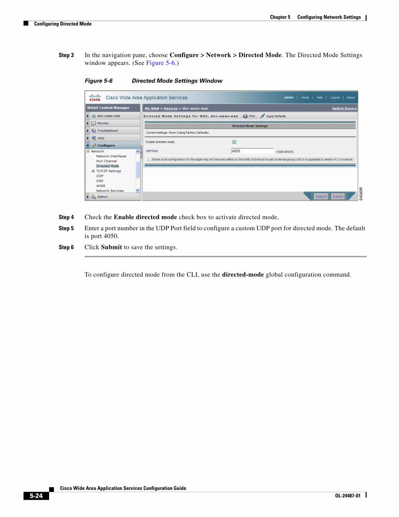
Step 3 In the navigation pane, choose Configure > Network > Directed Mode. The Directed Mode Settings window appears. (See Figure 5-6.)
Figure 5-6 Directed Mode Settings Window
Step 4 Check the Enable directed mode check box to activate directed mode.
Step 5 Enter a port number in the UDP Port field to configure a custom UDP port for directed mode. The default is port 4050.
Step 6 Click Submit to save the settings.
To configure directed mode from the CLI, use the directed-mode global configuration command.
![Configuring the Quota Manager - cisco.com€¦ · † Configuring the Quota Manager—Example, page 3-9 Configuring the Quota Profile Settings The [Quota Profile.QUOTA-PROFILE-NAME]](https://img.dokumen.tips/doc/110x75/5f0783767e708231d41d5b40/configuring-the-quota-manager-ciscocom-a-configuring-the-quota-manageraexample.jpg)