Embed Size (px)
Citation preview
Cisco IOS XOL-24754-01
C H A P T E R 4
Configuring General Router FeaturesThis chapter describes how to communicate with the router using the command-line interface (CLI), and it also shows basic Cisco IOS XR software configuration management.
Contents• Secure Domain Routers, page 4-71
• Connecting and Communicating with the Router, page 4-72
• Logging In to a Router or an SDR, page 4-82
• CLI Prompt, page 4-83
• User Access Privileges, page 4-83
• Navigating the Cisco IOS XR Command Modes, page 4-88
• Managing Configuration Sessions, page 4-94
• Configuring the SDR Hostname, page 4-111
• Configuring the Management Ethernet Interface, page 4-111
• Manually Setting the Router Clock, page 4-117
• Where to Go Next, page 4-119
Secure Domain RoutersCisco CRS routers can be partitioned into multiple, independent routers known as secure domain routers (SDRs). Every router is shipped with a default SDR, which is called the owner SDR, by default, owns all RPs and Line Cards (LCs) installed in the routing system. To build additional SDRs, you must perform the following steps:
• Create each SDR using configuration commands
• Name the SDR
• Assign RP, DRP and LCs to the SDR
• Configure the interfaces on the LCs on the new SDR
An SDR is a group of cards within a router that is configured to operate as an independent router. SDRs that are created with configuration commands are called SDRs and are configured with custom names to distinguish them from the owner SDR and other named SDRs.
4-71R Getting Started Guide for the Cisco CRS-1 Router
Chapter 4 Configuring General Router Features Connecting and Communicating with the Router
Note In previous releases, SDRs were called logical routers (LRs).
SDRs perform routing functions in the same manner as a physical router, but share some chassis resources with the rest of the system. For example, the applications, configurations, protocols, and routing tables assigned to an SDR belong to that SDR only, but other functions, such as chassis control, switch fabric, and partitioning, are shared with the rest of the system.
To manage the owner SDR, you must connect to the active RP for the owner SDR. In administration configuration mode, you can define new SDRs and assign resources to them (such as DRPs, MSCs, and line cards). In configuration mode, you can configure the operation of the owner SDR. Although you can reassign cards from one SDR to another, you cannot configure and manage cards assigned to a named SDR. To manage cards assigned to a named SDR, you must connect to the appropriate named SDR.
When you manage a named SDR, you must connect to the active RP for that named SDR. You can connect to the named SDR using any of the connection methods you use for the owner SDR (for example, you can connect through the console port or the Management Ethernet interface), and you have control over only the cards assigned to that named SDR. For example, you cannot configure and manage interfaces on LCs assigned to the owner SDR or other SDRs unless you connect directly to those SDRs.
Note Cisco IOS XR Software Releases 2.0, 3.0, and 3.2 support only one SDR on the Cisco CRS router.Cisco IOS XR Software Release 3.3 and later releases support multiple SDRs on the Cisco CRS routers and Cisco XR 12000 Series Routers. For more information, see Cisco IOS XR System Management Configuration Guide for the Cisco CRS Router.
Connecting and Communicating with the RouterTo manage or configure a router running Cisco IOS XR software, you must first connect to the router using a terminal or a PC. Before you connect to the router, you must determine which router entity to manage. You can manage the following router entities:
• Owner SDR. Connect to the designated shelf controller (DSC).
• Router or multishelf system hardware. Connect to the DSC.
• Named SDR. For Cisco CRS routers, connect to the RP or DRP that serves as the designated SDR shelf controller (DSDRSC) for that named SDR.
Connections are made either through a direct physical connection to the console port of the DSC or DSDRSC or from a remote location using a modem or an Ethernet connection that leads to the DSC or DSDRSC.
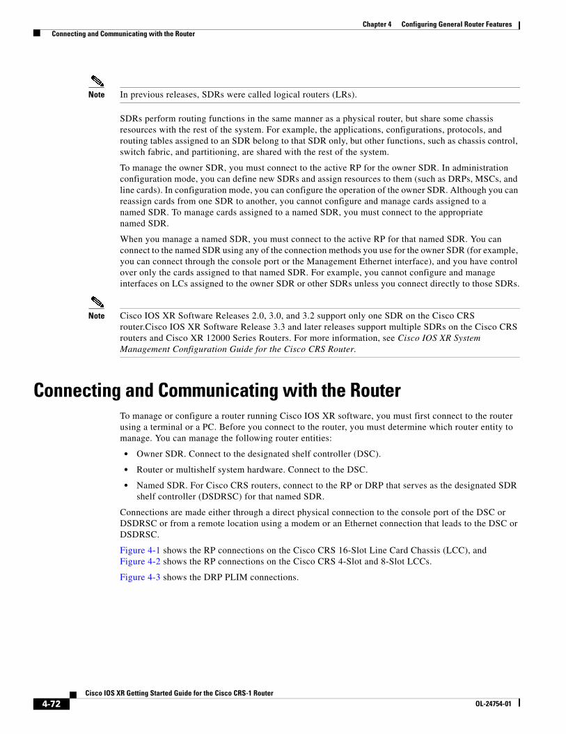
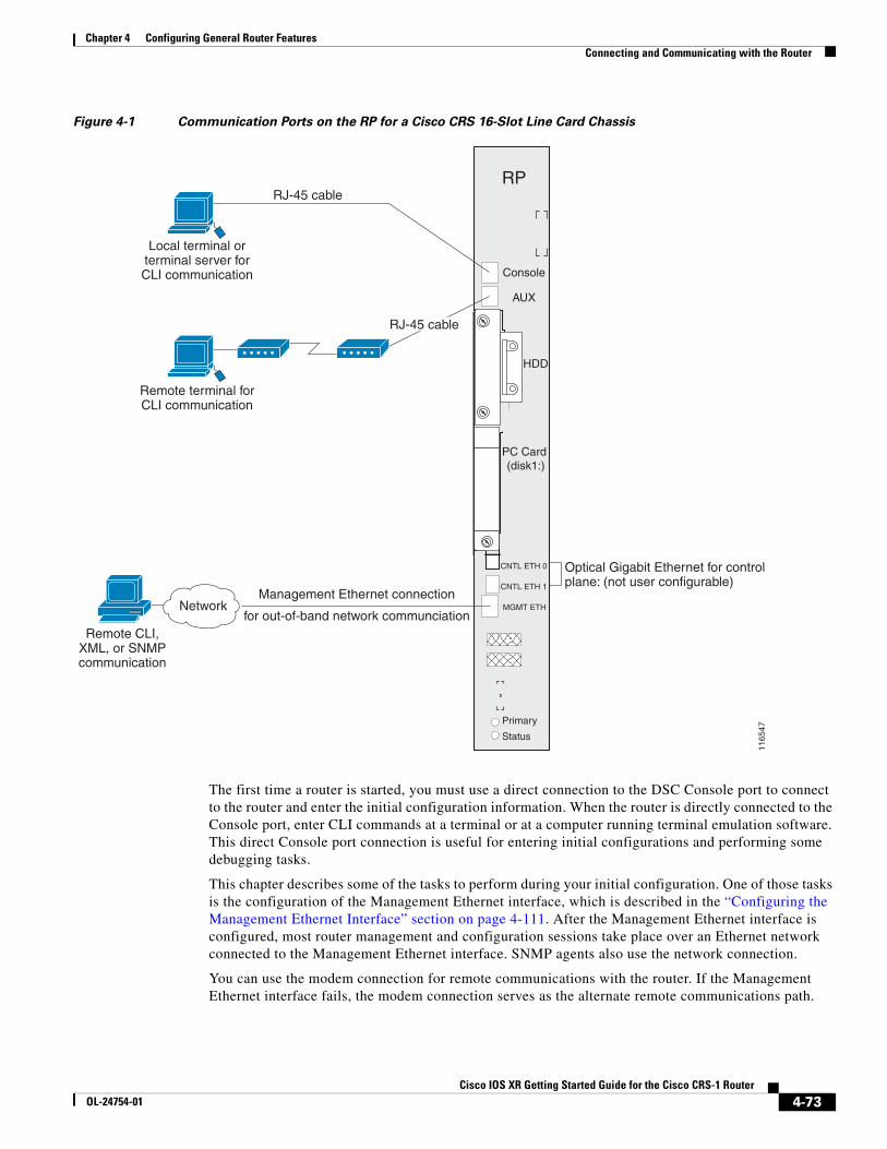
Figure 4-1 shows the RP connections on the Cisco CRS 16-Slot Line Card Chassis (LCC), and Figure 4-2 shows the RP connections on the Cisco CRS 4-Slot and 8-Slot LCCs.
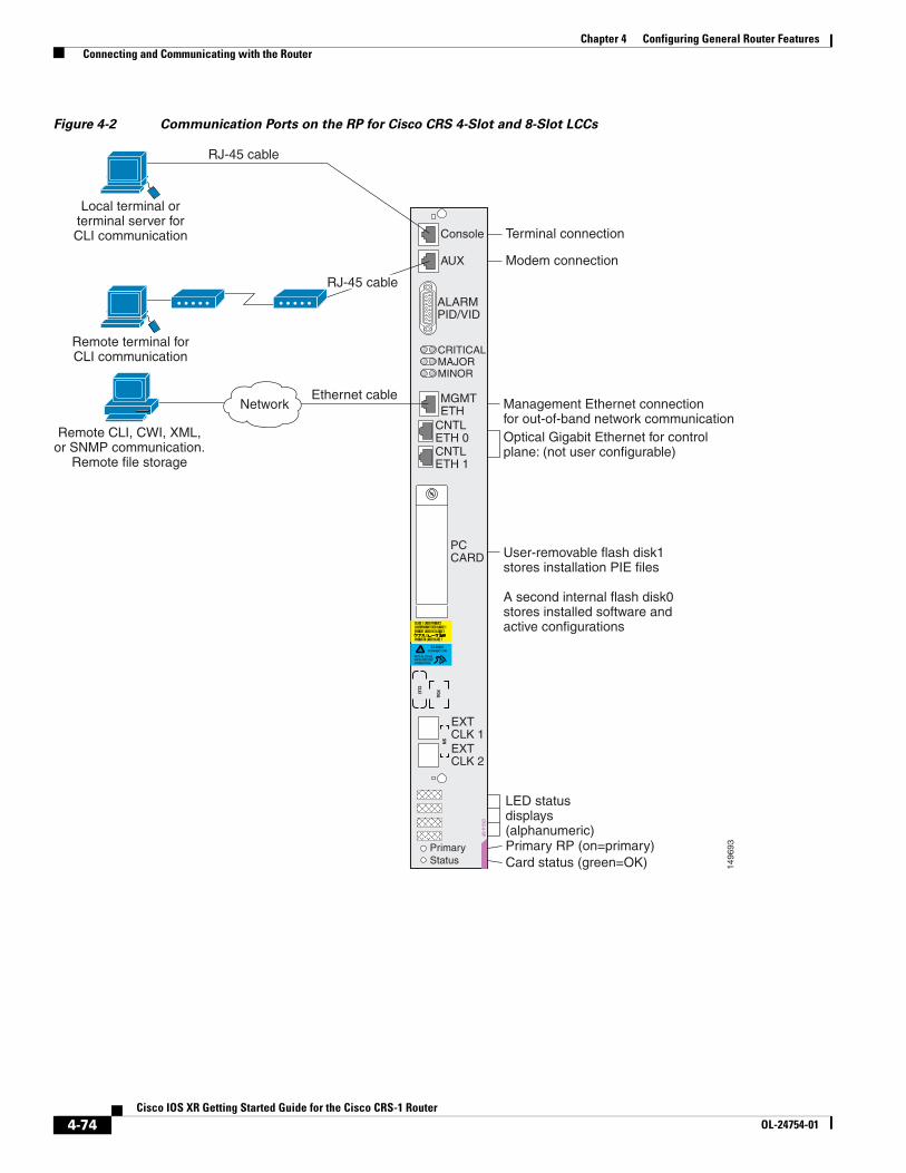
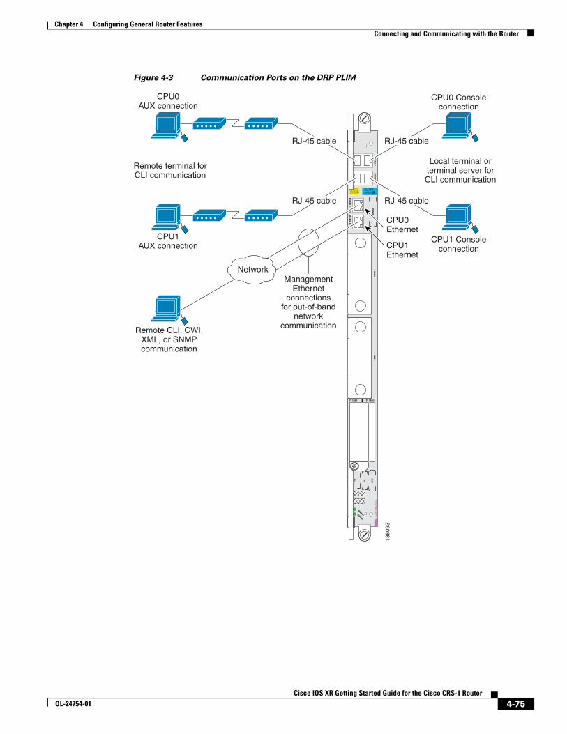
Figure 4-3 shows the DRP PLIM connections.
4-72Cisco IOS XR Getting Started Guide for the Cisco CRS-1 Router
OL-24754-01
Chapter 4 Configuring General Router Features Connecting and Communicating with the Router
Figure 4-1 Communication Ports on the RP for a Cisco CRS 16-Slot Line Card Chassis
The first time a router is started, you must use a direct connection to the DSC Console port to connect to the router and enter the initial configuration information. When the router is directly connected to the Console port, enter CLI commands at a terminal or at a computer running terminal emulation software. This direct Console port connection is useful for entering initial configurations and performing some debugging tasks.
This chapter describes some of the tasks to perform during your initial configuration. One of those tasks is the configuration of the Management Ethernet interface, which is described in the “Configuring the Management Ethernet Interface” section on page 4-111. After the Management Ethernet interface is configured, most router management and configuration sessions take place over an Ethernet network connected to the Management Ethernet interface. SNMP agents also use the network connection.
You can use the modem connection for remote communications with the router. If the Management Ethernet interface fails, the modem connection serves as the alternate remote communications path.
Console
AUX
PC Card (disk1:)
MGMT ETH
CNTL ETH 1
CNTL ETH 0
Primary
Status
HDD
RP
Local terminal orterminal server forCLI communication
Remote terminal forCLI communication
RJ-45 cable
Remote CLI,XML, or SNMPcommunication
RJ-45 cable
Optical Gigabit Ethernet for controlplane: (not user configurable)
1165
47
NetworkManagement Ethernet connection
for out-of-band network communciation
4-73Cisco IOS XR Getting Started Guide for the Cisco CRS-1 Router
OL-24754-01
Chapter 4 Configuring General Router Features Connecting and Communicating with the Router
Figure 4-2 Communication Ports on the RP for Cisco CRS 4-Slot and 8-Slot LCCs
PrimaryStatus
Console
AUX
CRITICALMAJORMINOR
1496
93
Optical Gigabit Ethernet for controlplane: (not user configurable)
Terminal connection
Modem connection
Primary RP (on=primary)Card status (green=OK)
User-removable flash disk1stores installation PIE files
A second internal flash disk0stores installed software and active configurations
Management Ethernet connectionfor out-of-band network communication
LED statusdisplays(alphanumeric)
ALARMPID/VID
MGMTETH
CNTLETH 0
PCCARD
CNTLETH 1
EXTCLK 1EXTCLK 2
Remote terminal forCLI communication
RJ-45 cable
Local terminal orterminal server forCLI communication
RJ-45 cable
Remote CLI, CWI, XML,or SNMP communication.
Remote file storage
Ethernet cableNetwork
4-74Cisco IOS XR Getting Started Guide for the Cisco CRS-1 Router
OL-24754-01
Chapter 4 Configuring General Router Features Connecting and Communicating with the Router
Figure 4-3 Communication Ports on the DRP PLIM
STATUS
PRIMARY
CLASS 1 LASER PRODUCTLASERPRODUKT DER KLASSE 1PRODUIT LASER DE CLASSE 1
PRODUCTO LASER CLASE 111
CLEANCONNECTOR
WITH ALCOHOLWIPES BEFORECONNECTING
PID
VID
PID
VID
SN
CL
EI
FD
A
AU
X 0
AU
X 1
MG
MT E
TH 1
MG
MT E
TH 0
B1
CR
S-D
RP
-AC
C
1380
93
Network
CPU0AUX connection
CPU0 Consoleconnection
CPU1AUX connection
CPU1 Consoleconnection
Remote CLI, CWI,XML, or SNMPcommunication
ManagementEthernet
connectionsfor out-of-band
networkcommunication
CPU0Ethernet
CPU1Ethernet
RJ-45 cable
RJ-45 cable
RJ-45 cable
RJ-45 cable
Local terminal orterminal server forCLI communication
Remote terminal forCLI communication
4-75Cisco IOS XR Getting Started Guide for the Cisco CRS-1 Router
OL-24754-01
Chapter 4 Configuring General Router Features Connecting and Communicating with the Router
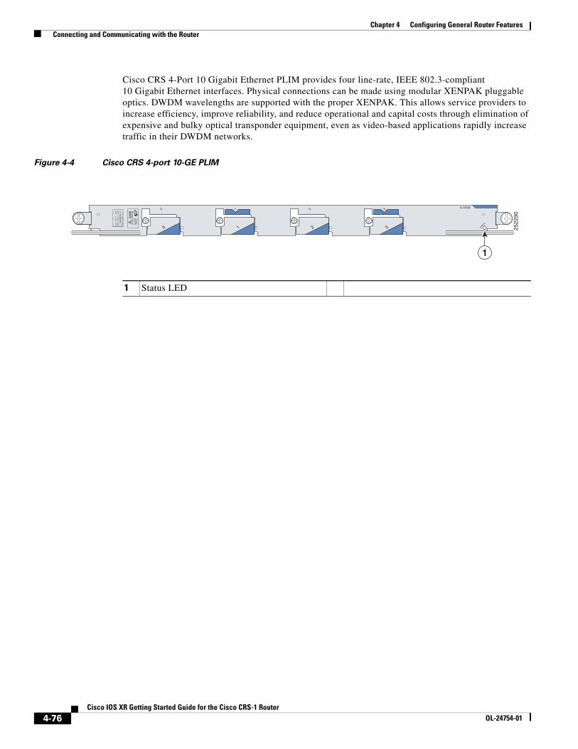
Cisco CRS 4-Port 10 Gigabit Ethernet PLIM provides four line-rate, IEEE 802.3-compliant 10 Gigabit Ethernet interfaces. Physical connections can be made using modular XENPAK pluggable optics. DWDM wavelengths are supported with the proper XENPAK. This allows service providers to increase efficiency, improve reliability, and reduce operational and capital costs through elimination of expensive and bulky optical transponder equipment, even as video-based applications rapidly increase traffic in their DWDM networks.
Figure 4-4 Cisco CRS 4-port 10-GE PLIM
B1 2522
90
1
00
1 22 3
4-10GE3
CLEA
NCO
NNEC
TOR
WIT
H AL
COHO
LW
IPES
BEF
ORE
CONN
ECTI
NG
STATUS
1
1 Status LED
4-76Cisco IOS XR Getting Started Guide for the Cisco CRS-1 Router
OL-24754-01
Chapter 4 Configuring General Router Features Connecting and Communicating with the Router
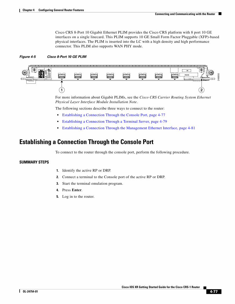
Cisco CRS 8-Port 10 Gigabit Ethernet PLIM provides the Cisco CRS platform with 8 port 10 GE interfaces on a single linecard. This PLIM supports 10 GE Small Form Factor Pluggable (XFP)-based physical interfaces. The PLIM is inserted into the LC with a high density and high performance connector. This PLIM also supports WAN PHY mode.
Figure 4-5 Cisco 8-Port 10 GE PLIM
For more information about Gigabit PLIMs, see the Cisco CRS Carrier Routing System Ethernet Physical Layer Interface Module Installation Note.
The following sections describe three ways to connect to the router:
• Establishing a Connection Through the Console Port, page 4-77
• Establishing a Connection Through a Terminal Server, page 4-79
• Establishing a Connection Through the Management Ethernet Interface, page 4-81
Establishing a Connection Through the Console PortTo connect to the router through the console port, perform the following procedure.
SUMMARY STEPS
1. Identify the active RP or DRP.
2. Connect a terminal to the Console port of the active RP or DRP.
3. Start the terminal emulation program.
4. Press Enter.
5. Log in to the router.
2488
50!C
LEA
NC
ON
NE
CTO
R
WIT
H A
LCO
HO
LW
IPE
S B
EFO
RE
CO
NN
EC
TIN
G
PID/VID
SN
STATUS
1 2
4-77Cisco IOS XR Getting Started Guide for the Cisco CRS-1 Router
OL-24754-01
Chapter 4 Configuring General Router Features Connecting and Communicating with the Router
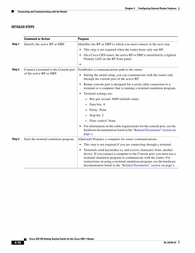
DETAILED STEPS
Command or Action Purpose
Step 1 Identify the active RP or DRP. Identifies the RP or DRP to which you must connect in the next step.
• This step is not required when the router hosts only one RP.
• On a Cisco CRS router, the active RP or DRP is identified by a lighted Primary LED on the RP front panel.
•
Step 2 Connect a terminal to the Console port of the active RP or DRP.
Establishes a communications path to the router.
• During the initial setup, you can communicate with the router only through the console port of the active RP.
• Router console port is designed for a serial cable connection to a terminal or a computer that is running a terminal emulation program.
• Terminal settings are:
– Bits per second: 9600 (default value)
– Data bits: 8
– Parity: None
– Stop bit: 2
– Flow control: None
• For information on the cable requirements for the console port, see the hardware documentation listed in the “Related Documents” section on page x.
Step 3 Start the terminal emulation program. (Optional) Prepares a computer for router communications.
• This step is not required if you are connecting through a terminal.
• Terminals send keystrokes to, and receive characters from, another device. If you connect a computer to the Console port, you must use a terminal emulation program to communicate with the router. For instructions on using a terminal emulation program, see the hardware documentation listed in the “Related Documents” section on page x.
4-78Cisco IOS XR Getting Started Guide for the Cisco CRS-1 Router
OL-24754-01
Chapter 4 Configuring General Router Features Connecting and Communicating with the Router
Establishing a Connection Through a Terminal ServerA terminal server connection provides a way to access the Console port from a remote location. It is less expensive to connect to the router through the Management Ethernet interface (because you do not have the additional cost of a terminal server). However, if you need to perform tasks that require Console port access from a remote location, a terminal server is the best method.
The procedure for connecting to the router through a terminal server is similar to the procedure for directly connecting through the Console port. For both connection types, the physical connection takes place through the Console port. The difference is that the terminal server connects directly to the Console port, and you must use a Telnet session to establish communications through the terminal server to the router.
To establish a connection through a terminal server, perform the following procedure.
SUMMARY STEPS
1. Install and configure the terminal server.
2. Connect the terminal server to the Console port of the target RP or DRP.
3. Power on the router.
4. Identify the target RP or DRP.
5. telnet access-server-address port
6. Press Enter.
7. Log in to the router.
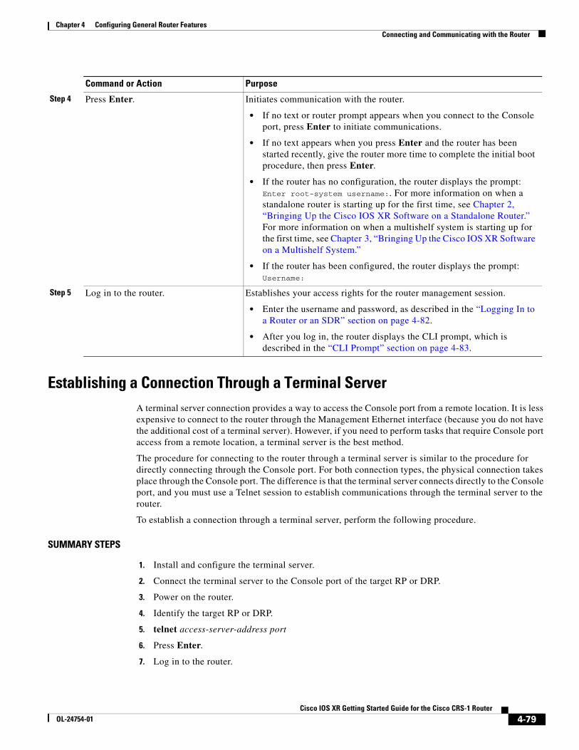
Step 4 Press Enter. Initiates communication with the router.
• If no text or router prompt appears when you connect to the Console port, press Enter to initiate communications.
• If no text appears when you press Enter and the router has been started recently, give the router more time to complete the initial boot procedure, then press Enter.
• If the router has no configuration, the router displays the prompt: Enter root-system username:. For more information on when a standalone router is starting up for the first time, see Chapter 2, “Bringing Up the Cisco IOS XR Software on a Standalone Router.” For more information on when a multishelf system is starting up for the first time, see Chapter 3, “Bringing Up the Cisco IOS XR Software on a Multishelf System.”
• If the router has been configured, the router displays the prompt: Username:
Step 5 Log in to the router. Establishes your access rights for the router management session.
• Enter the username and password, as described in the “Logging In to a Router or an SDR” section on page 4-82.
• After you log in, the router displays the CLI prompt, which is described in the “CLI Prompt” section on page 4-83.
Command or Action Purpose
4-79Cisco IOS XR Getting Started Guide for the Cisco CRS-1 Router
OL-24754-01
Chapter 4 Configuring General Router Features Connecting and Communicating with the Router
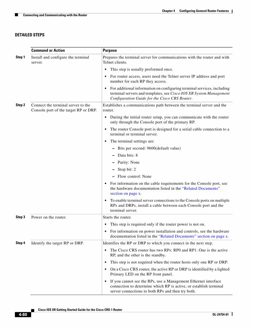
DETAILED STEPS
Command or Action Purpose
Step 1 Install and configure the terminal server.
Prepares the terminal server for communications with the router and with Telnet clients.
• This step is usually preformed once.
• For router access, users need the Telnet server IP address and port number for each RP they access.
• For additional information on configuring terminal services, including terminal servers and templates, see Cisco IOS XR System Management Configuration Guide for the Cisco CRS Router.
Step 2 Connect the terminal server to the Console port of the target RP or DRP.
Establishes a communications path between the terminal server and the router.
• During the initial router setup, you can communicate with the router only through the Console port of the primary RP.
• The router Console port is designed for a serial cable connection to a terminal or terminal server.
• The terminal settings are:
– Bits per second: 9600(default value)
– Data bits: 8
– Parity: None
– Stop bit: 2
– Flow control: None
• For information on the cable requirements for the Console port, see the hardware documentation listed in the “Related Documents” section on page x.
• To enable terminal server connections to the Console ports on multiple RPs and DRPs, install a cable between each Console port and the terminal server.
Step 3 Power on the router. Starts the router.
• This step is required only if the router power is not on.
• For information on power installation and controls, see the hardware documentation listed in the “Related Documents” section on page x.
Step 4 Identify the target RP or DRP. Identifies the RP or DRP to which you connect in the next step.
• The Cisco CRS router has two RPs: RP0 and RP1. One is the active RP, and the other is the standby.
• This step is not required when the router hosts only one RP or DRP.
• On a Cisco CRS router, the active RP or DRP is identified by a lighted Primary LED on the RP front panel.
• If you cannot see the RPs, use a Management Ethernet interface connection to determine which RP is active, or establish terminal server connections to both RPs and then try both.
4-80Cisco IOS XR Getting Started Guide for the Cisco CRS-1 Router
OL-24754-01
Chapter 4 Configuring General Router Features Connecting and Communicating with the Router
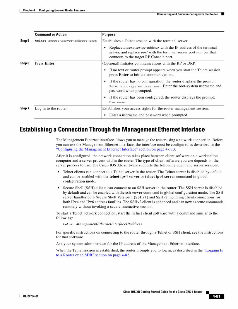
Establishing a Connection Through the Management Ethernet InterfaceThe Management Ethernet interface allows you to manage the router using a network connection. Before you can use the Management Ethernet interface, the interface must be configured as described in the “Configuring the Management Ethernet Interface” section on page 4-113.
After it is configured, the network connection takes place between client software on a workstation computer and a server process within the router. The type of client software you use depends on the server process to use. The Cisco IOS XR software supports the following client and server services:
• Telnet clients can connect to a Telnet server in the router. The Telnet server is disabled by default and can be enabled with the telnet ipv4 server or telnet ipv6 server command in global configuration mode.
• Secure Shell (SSH) clients can connect to an SSH server in the router. The SSH server is disabled by default and can be enabled with the ssh server command in global configuration mode. The SSH server handles both Secure Shell Version 1 (SSHv1) and SSHv2 incoming client connections for both IPv4 and IPv6 address families. The SSHv2 client is enhanced and can now execute commands remotely without invoking a secure interactive session.
To start a Telnet network connection, start the Telnet client software with a command similar to the following:
telnet ManagementEthernetInterfaceIPaddress
For specific instructions on connecting to the router through a Telnet or SSH client, see the instructions for that software.
Ask your system administrator for the IP address of the Management Ethernet interface.
When the Telnet session is established, the router prompts you to log in, as described in the “Logging In to a Router or an SDR” section on page 4-82.
Step 5 telnet access-server-address port Establishes a Telnet session with the terminal server.
• Replace access-server-address with the IP address of the terminal server, and replace port with the terminal server port number that connects to the target RP Console port.
Step 6 Press Enter. (Optional) Initiates communications with the RP or DRP.
• If no text or router prompt appears when you start the Telnet session, press Enter to initiate communications.
• If the router has no configuration, the router displays the prompt: Enter root-system username: Enter the root-system username and password when prompted.
• If the router has been configured, the router displays the prompt: Username:
Step 7 Log in to the router. Establishes your access rights for the router management session.
• Enter a username and password when prompted.
Command or Action Purpose
4-81Cisco IOS XR Getting Started Guide for the Cisco CRS-1 Router
OL-24754-01
Chapter 4 Configuring General Router Features Logging In to a Router or an SDR
Logging In to a Router or an SDRThe login process can require users to enter a password or a username and password before accessing the router CLI. The user groups to which your username is assigned determine which commands you can use.
If you log in to a router with a single SDR configured (this is the default configuration), you can manage the entire router. If you log in to the owner SDR on a system with multiple SDRs, you can manage general features that apply to the entire system and the interfaces assigned to the owner SDR. If you log in to a named SDR, you can manage only that SDR. For more information on SDRs, see the “Secure Domain Routers” section on page 4-71.
When you log in, the username and password may be validated by any of the following services:
• Usernames configured on the router (username command in global configuration mode)
• Root-system usernames configured on the owner SDR
• Passwords configured for the router console and auxiliary ports (password or secret command in line configuration mode)
• RADIUS server
• TACACS+ server
The username and password validation method that your router uses is determined by the router configuration. For information on configuring username and password validation methods, see Cisco IOS XR System Security Configuration Guide for the Cisco CRS Router. For information on which username and password to use, see your system administrator.
To log in to the router, enter your username and password when prompted. For example:
User Access Verification
Username: iosxrPassword: passwordRP/0/RP0/CPU0:router#
Note Passwords are case sensitive. To log in to an SDR using a root-system username from the owner SDR, enter the username in the following format: username@admin. To support admin login, local database authentication must be enabled with the aaa authentication login remote local command. For more information, see Cisco IOS XR System Security Configuration Guide for the Cisco CRS Router.
After you log in, the router displays the CLI prompt, which is described in the “CLI Prompt” section on page 4-83. The command set that you can use is determined by the privileges assigned to your username. For information on how privileges are assigned to usernames, see Cisco IOS XR System Security Configuration Guide for the Cisco CRS Router.
4-82Cisco IOS XR Getting Started Guide for the Cisco CRS-1 Router
OL-24754-01
Chapter 4 Configuring General Router Features CLI Prompt
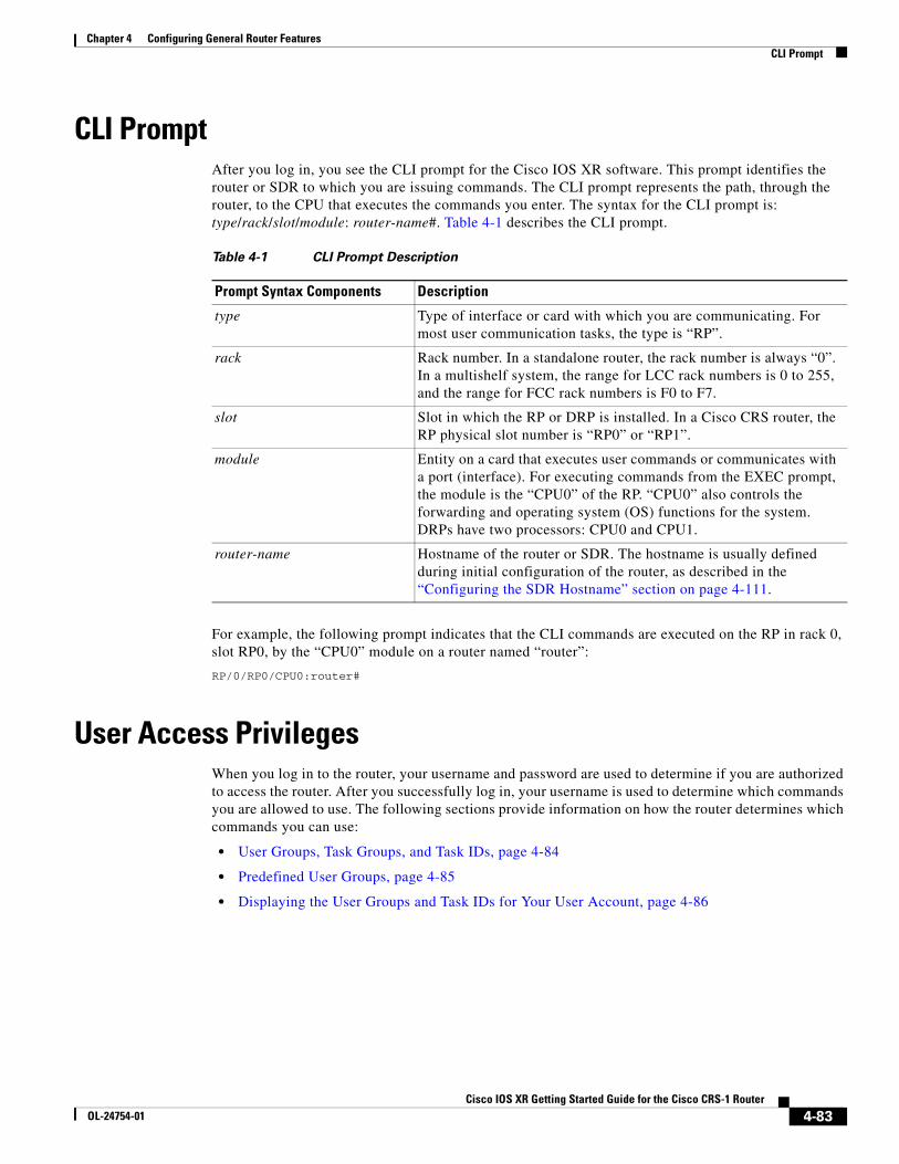
CLI PromptAfter you log in, you see the CLI prompt for the Cisco IOS XR software. This prompt identifies the router or SDR to which you are issuing commands. The CLI prompt represents the path, through the router, to the CPU that executes the commands you enter. The syntax for the CLI prompt is: type/rack/slot/module: router-name#. Table 4-1 describes the CLI prompt.
For example, the following prompt indicates that the CLI commands are executed on the RP in rack 0, slot RP0, by the “CPU0” module on a router named “router”:
RP/0/RP0/CPU0:router#
User Access PrivilegesWhen you log in to the router, your username and password are used to determine if you are authorized to access the router. After you successfully log in, your username is used to determine which commands you are allowed to use. The following sections provide information on how the router determines which commands you can use:
• User Groups, Task Groups, and Task IDs, page 4-84
• Predefined User Groups, page 4-85
• Displaying the User Groups and Task IDs for Your User Account, page 4-86
Table 4-1 CLI Prompt Description
Prompt Syntax Components Description
type Type of interface or card with which you are communicating. For most user communication tasks, the type is “RP”.
rack Rack number. In a standalone router, the rack number is always “0”. In a multishelf system, the range for LCC rack numbers is 0 to 255, and the range for FCC rack numbers is F0 to F7.
slot Slot in which the RP or DRP is installed. In a Cisco CRS router, the RP physical slot number is “RP0” or “RP1”.
module Entity on a card that executes user commands or communicates with a port (interface). For executing commands from the EXEC prompt, the module is the “CPU0” of the RP. “CPU0” also controls the forwarding and operating system (OS) functions for the system. DRPs have two processors: CPU0 and CPU1.
router-name Hostname of the router or SDR. The hostname is usually defined during initial configuration of the router, as described in the “Configuring the SDR Hostname” section on page 4-111.
4-83Cisco IOS XR Getting Started Guide for the Cisco CRS-1 Router
OL-24754-01
Chapter 4 Configuring General Router Features User Access Privileges
User Groups, Task Groups, and Task IDsThe Cisco IOS XR software ensures security by combining tasks a user wants to perform (task IDs) into groups, defining which router configuration and management functions users can perform. This policy is enabled by the definition of:
• User groups—Collection of users that share similar authorization rights on a router.
• Task groups—Definition of collection of tasks identified by unique task IDs for each class of action.
• Task IDs—Definition of permission to perform particular tasks; pooled into a task group that is then assigned to users.
The commands you can perform are defined by the user groups to which you belong. Within the Cisco IOS XR software, the commands for a particular feature, like access control lists, are assigned to tasks. Each task is uniquely identified by a task ID. To use a particular command, your username must be associated with the appropriate task ID.
The association between a username and a task ID takes place through two intermediate entities, the user group and task group.
The user group is a logical container used to assign the same task IDs to multiple users. Instead of assigning task IDs to each user, you can assign them to the user group. Then, you can assign users to that user group. When a task is assigned to a user group, you can define the access rights for the commands associated with that task. These rights include “read”, “write”, “execute”, and “notify”.
The task group is also a logical container, but it is used to group tasks. Instead of assigning task IDs to each user group, you assign them to a task group. This allows you to quickly enable access to a specific set of tasks by assigning a task group to a user group.
To summarize the associations, usernames are assigned to user groups, which are then assigned to task groups. Users can be assigned to multiple user groups, and each user group can be assigned to one or more task groups. The commands that a user can execute are all those commands assigned to the tasks within the task groups that are associated with the user groups to which the user belongs.
Users are not assigned to groups by default and must be explicitly assigned by an administrator.
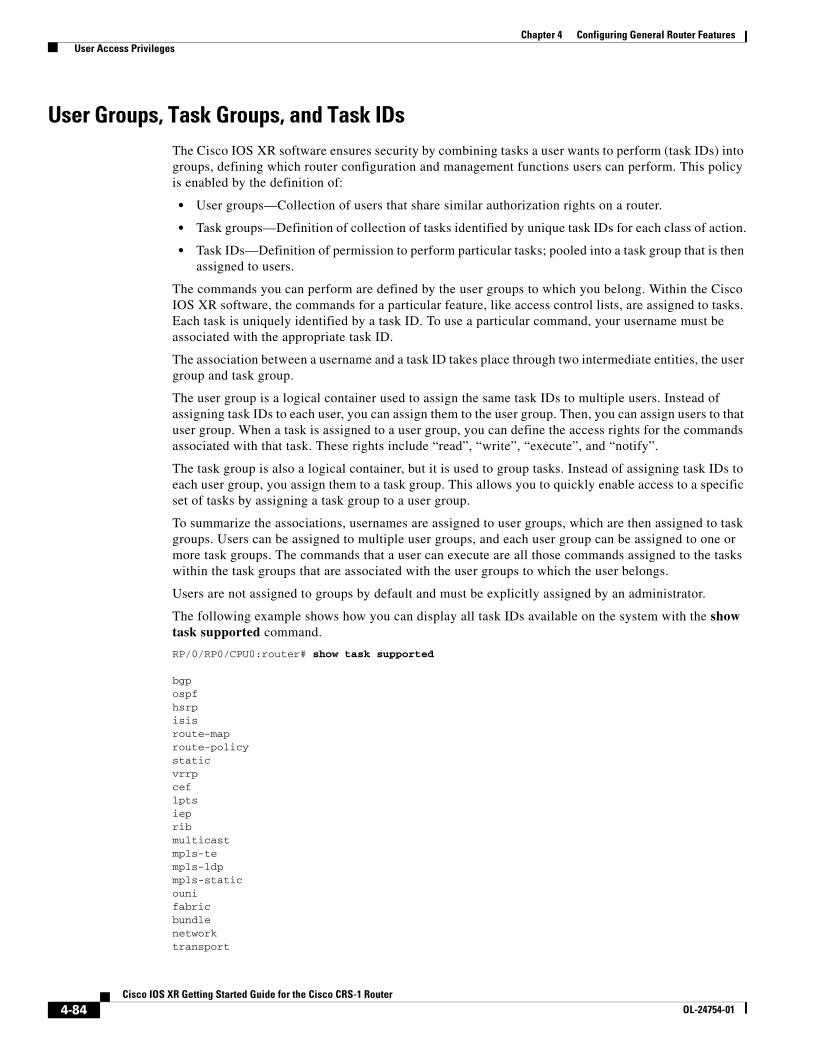
The following example shows how you can display all task IDs available on the system with the show task supported command.
RP/0/RP0/CPU0:router# show task supported
bgpospfhsrpisisroute-maproute-policystaticvrrpceflptsiepribmulticastmpls-templs-ldpmpls-staticounifabricbundlenetworktransport
4-84Cisco IOS XR Getting Started Guide for the Cisco CRS-1 Router
OL-24754-01
Chapter 4 Configuring General Router Features User Access Privileges
ppphdlc --More--
Note Only the root-system users, root-lr users, or users associated with the WRITE:AAA task ID can configure task groups. (The root-lr user has the highest level of privileges in an SDR. In previous releases, SDRs were called logical routers [LRs].)
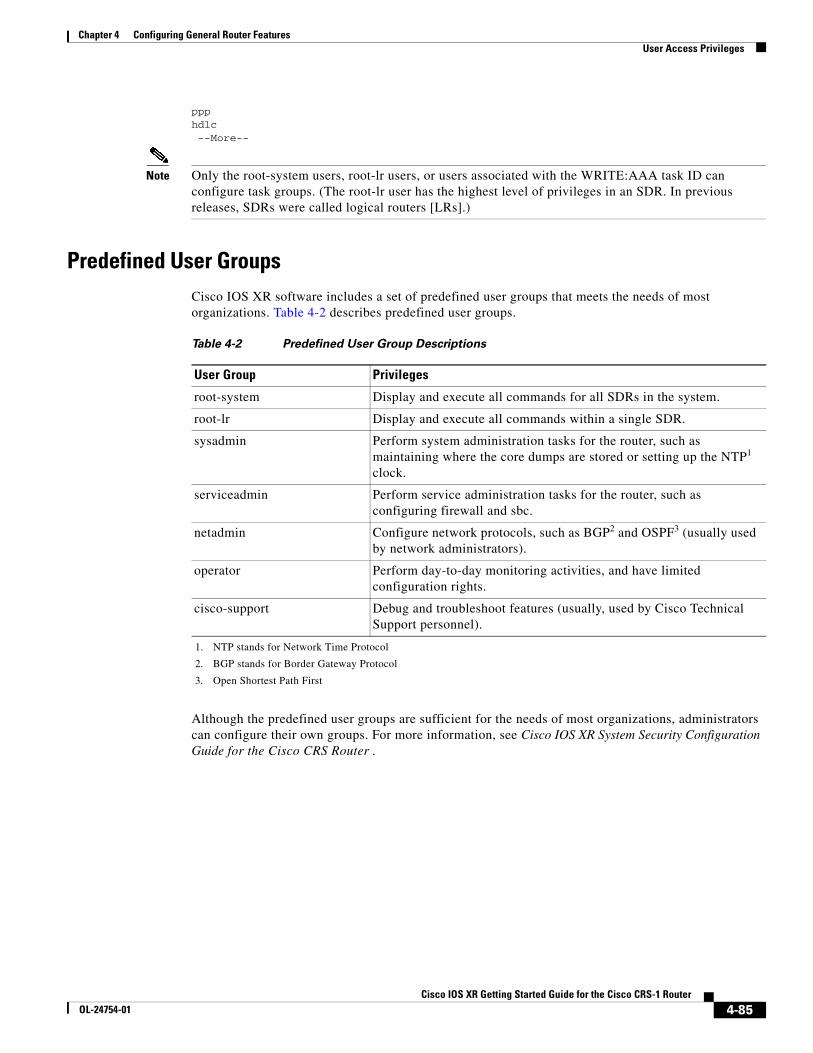
Predefined User GroupsCisco IOS XR software includes a set of predefined user groups that meets the needs of most organizations. Table 4-2 describes predefined user groups.
Although the predefined user groups are sufficient for the needs of most organizations, administrators can configure their own groups. For more information, see Cisco IOS XR System Security Configuration Guide for the Cisco CRS Router .
Table 4-2 Predefined User Group Descriptions
User Group Privileges
root-system Display and execute all commands for all SDRs in the system.
root-lr Display and execute all commands within a single SDR.
sysadmin Perform system administration tasks for the router, such as maintaining where the core dumps are stored or setting up the NTP1 clock.
1. NTP stands for Network Time Protocol
serviceadmin Perform service administration tasks for the router, such as configuring firewall and sbc.
netadmin Configure network protocols, such as BGP2 and OSPF3 (usually used by network administrators).
2. BGP stands for Border Gateway Protocol
3. Open Shortest Path First
operator Perform day-to-day monitoring activities, and have limited configuration rights.
cisco-support Debug and troubleshoot features (usually, used by Cisco Technical Support personnel).
4-85Cisco IOS XR Getting Started Guide for the Cisco CRS-1 Router
OL-24754-01
Chapter 4 Configuring General Router Features User Access Privileges
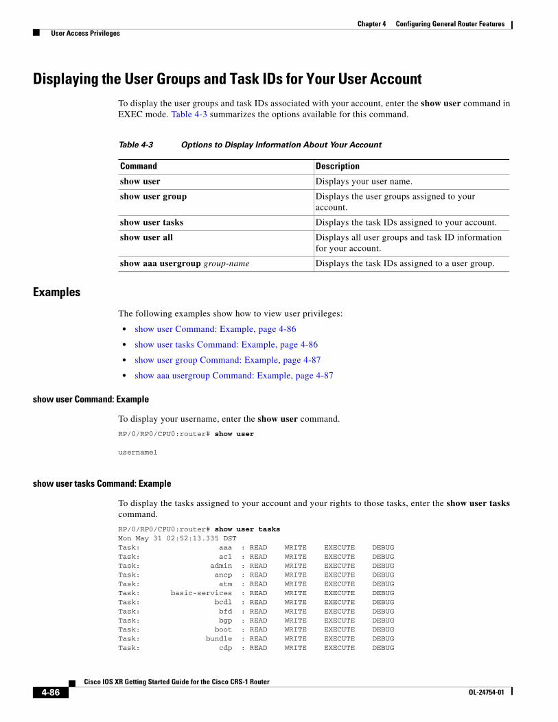
Displaying the User Groups and Task IDs for Your User Account To display the user groups and task IDs associated with your account, enter the show user command in EXEC mode. Table 4-3 summarizes the options available for this command.
Examples
The following examples show how to view user privileges:
• show user Command: Example, page 4-86
• show user tasks Command: Example, page 4-86
• show user group Command: Example, page 4-87
• show aaa usergroup Command: Example, page 4-87
show user Command: Example
To display your username, enter the show user command.
RP/0/RP0/CPU0:router# show user
username1
show user tasks Command: Example
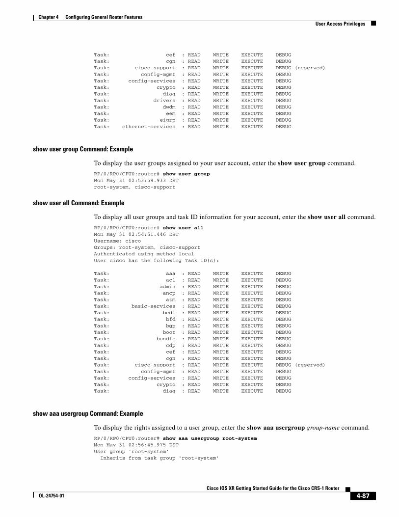
To display the tasks assigned to your account and your rights to those tasks, enter the show user tasks command.
RP/0/RP0/CPU0:router# show user tasksMon May 31 02:52:13.335 DSTTask: aaa : READ WRITE EXECUTE DEBUGTask: acl : READ WRITE EXECUTE DEBUGTask: admin : READ WRITE EXECUTE DEBUGTask: ancp : READ WRITE EXECUTE DEBUGTask: atm : READ WRITE EXECUTE DEBUGTask: basic-services : READ WRITE EXECUTE DEBUGTask: bcdl : READ WRITE EXECUTE DEBUGTask: bfd : READ WRITE EXECUTE DEBUGTask: bgp : READ WRITE EXECUTE DEBUGTask: boot : READ WRITE EXECUTE DEBUGTask: bundle : READ WRITE EXECUTE DEBUGTask: cdp : READ WRITE EXECUTE DEBUG
Table 4-3 Options to Display Information About Your Account
Command Description
show user Displays your user name.
show user group Displays the user groups assigned to your account.
show user tasks Displays the task IDs assigned to your account.
show user all Displays all user groups and task ID information for your account.
show aaa usergroup group-name Displays the task IDs assigned to a user group.
4-86Cisco IOS XR Getting Started Guide for the Cisco CRS-1 Router
OL-24754-01
Chapter 4 Configuring General Router Features User Access Privileges
Task: cef : READ WRITE EXECUTE DEBUGTask: cgn : READ WRITE EXECUTE DEBUGTask: cisco-support : READ WRITE EXECUTE DEBUG (reserved)Task: config-mgmt : READ WRITE EXECUTE DEBUGTask: config-services : READ WRITE EXECUTE DEBUGTask: crypto : READ WRITE EXECUTE DEBUGTask: diag : READ WRITE EXECUTE DEBUGTask: drivers : READ WRITE EXECUTE DEBUGTask: dwdm : READ WRITE EXECUTE DEBUGTask: eem : READ WRITE EXECUTE DEBUGTask: eigrp : READ WRITE EXECUTE DEBUGTask: ethernet-services : READ WRITE EXECUTE DEBUG
show user group Command: Example
To display the user groups assigned to your user account, enter the show user group command.
RP/0/RP0/CPU0:router# show user groupMon May 31 02:53:59.933 DSTroot-system, cisco-support
show user all Command: Example
To display all user groups and task ID information for your account, enter the show user all command.
RP/0/RP0/CPU0:router# show user allMon May 31 02:54:51.446 DSTUsername: ciscoGroups: root-system, cisco-supportAuthenticated using method localUser cisco has the following Task ID(s):
Task: aaa : READ WRITE EXECUTE DEBUGTask: acl : READ WRITE EXECUTE DEBUGTask: admin : READ WRITE EXECUTE DEBUGTask: ancp : READ WRITE EXECUTE DEBUGTask: atm : READ WRITE EXECUTE DEBUGTask: basic-services : READ WRITE EXECUTE DEBUGTask: bcdl : READ WRITE EXECUTE DEBUGTask: bfd : READ WRITE EXECUTE DEBUGTask: bgp : READ WRITE EXECUTE DEBUGTask: boot : READ WRITE EXECUTE DEBUGTask: bundle : READ WRITE EXECUTE DEBUGTask: cdp : READ WRITE EXECUTE DEBUGTask: cef : READ WRITE EXECUTE DEBUGTask: cgn : READ WRITE EXECUTE DEBUGTask: cisco-support : READ WRITE EXECUTE DEBUG (reserved)Task: config-mgmt : READ WRITE EXECUTE DEBUGTask: config-services : READ WRITE EXECUTE DEBUGTask: crypto : READ WRITE EXECUTE DEBUGTask: diag : READ WRITE EXECUTE DEBUG
show aaa usergroup Command: Example
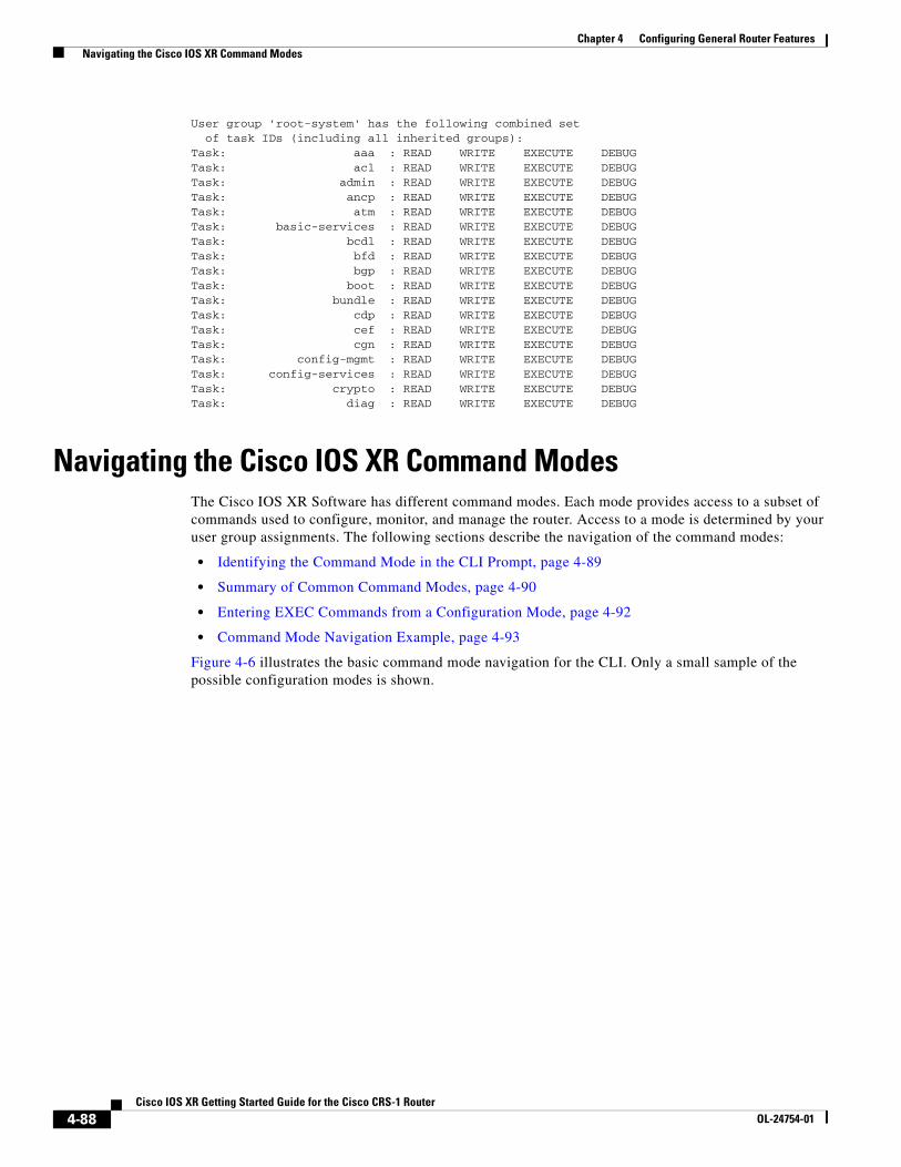
To display the rights assigned to a user group, enter the show aaa usergroup group-name command.
RP/0/RP0/CPU0:router# show aaa usergroup root-systemMon May 31 02:56:45.975 DSTUser group 'root-system' Inherits from task group 'root-system'
4-87Cisco IOS XR Getting Started Guide for the Cisco CRS-1 Router
OL-24754-01
Chapter 4 Configuring General Router Features Navigating the Cisco IOS XR Command Modes
User group 'root-system' has the following combined set of task IDs (including all inherited groups):Task: aaa : READ WRITE EXECUTE DEBUGTask: acl : READ WRITE EXECUTE DEBUGTask: admin : READ WRITE EXECUTE DEBUGTask: ancp : READ WRITE EXECUTE DEBUGTask: atm : READ WRITE EXECUTE DEBUGTask: basic-services : READ WRITE EXECUTE DEBUGTask: bcdl : READ WRITE EXECUTE DEBUGTask: bfd : READ WRITE EXECUTE DEBUGTask: bgp : READ WRITE EXECUTE DEBUGTask: boot : READ WRITE EXECUTE DEBUGTask: bundle : READ WRITE EXECUTE DEBUGTask: cdp : READ WRITE EXECUTE DEBUGTask: cef : READ WRITE EXECUTE DEBUGTask: cgn : READ WRITE EXECUTE DEBUGTask: config-mgmt : READ WRITE EXECUTE DEBUGTask: config-services : READ WRITE EXECUTE DEBUGTask: crypto : READ WRITE EXECUTE DEBUGTask: diag : READ WRITE EXECUTE DEBUG
Navigating the Cisco IOS XR Command Modes The Cisco IOS XR Software has different command modes. Each mode provides access to a subset of commands used to configure, monitor, and manage the router. Access to a mode is determined by your user group assignments. The following sections describe the navigation of the command modes:
• Identifying the Command Mode in the CLI Prompt, page 4-89
• Summary of Common Command Modes, page 4-90
• Entering EXEC Commands from a Configuration Mode, page 4-92
• Command Mode Navigation Example, page 4-93
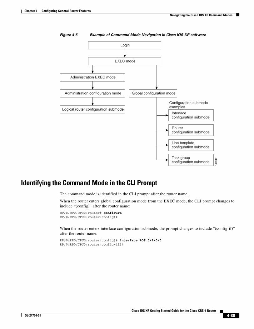
Figure 4-6 illustrates the basic command mode navigation for the CLI. Only a small sample of the possible configuration modes is shown.
4-88Cisco IOS XR Getting Started Guide for the Cisco CRS-1 Router
OL-24754-01
Chapter 4 Configuring General Router Features Navigating the Cisco IOS XR Command Modes
Figure 4-6 Example of Command Mode Navigation in Cisco IOS XR software
Identifying the Command Mode in the CLI PromptThe command mode is identified in the CLI prompt after the router name.
When the router enters global configuration mode from the EXEC mode, the CLI prompt changes to include “(config)” after the router name:
RP/0/RP0/CPU0:router# configureRP/0/RP0/CPU0:router(config)#
When the router enters interface configuration submode, the prompt changes to include “(config-if)” after the router name:
RP/0/RP0/CPU0:router(config)# interface POS 0/2/0/0RP/0/RP0/CPU0:router(config-if)#
1499
47
EXEC mode
Login
Interfaceconfiguration submode
Configuration submodeexamples
Routerconfiguration submode
Line templateconfiguration submode
Task groupconfiguration submode
Global configuration modeAdministration configuration mode
Logical router configuration submode
Administration EXEC mode
4-89Cisco IOS XR Getting Started Guide for the Cisco CRS-1 Router
OL-24754-01
Chapter 4 Configuring General Router Features Navigating the Cisco IOS XR Command Modes
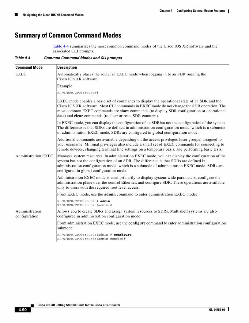
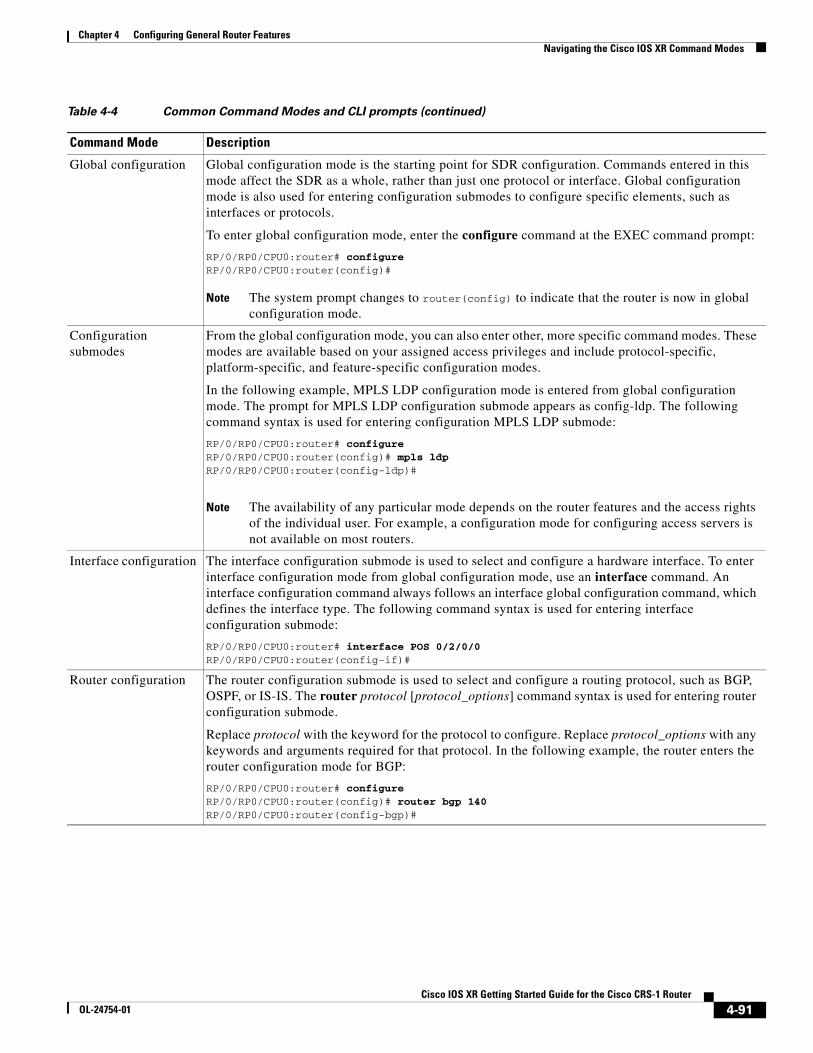
Summary of Common Command ModesTable 4-4 summarizes the most common command modes of the Cisco IOS XR software and the associated CLI prompts.
Table 4-4 Common Command Modes and CLI prompts
Command Mode Description
EXEC Automatically places the router in EXEC mode when logging in to an SDR running the Cisco IOS XR software.
Example:
RP/0/RP0/CPU0:router#
EXEC mode enables a basic set of commands to display the operational state of an SDR and the Cisco IOS XR software. Most CLI commands in EXEC mode do not change the SDR operation. The most common EXEC commands are show commands (to display SDR configuration or operational data) and clear commands (to clear or reset SDR counters).
In EXEC mode, you can display the configuration of an SDRbut not the configuration of the system. The difference is that SDRs are defined in administration configuration mode, which is a submode of administration EXEC mode. SDRs are configured in global configuration mode.
Additional commands are available depending on the access privileges (user groups) assigned to your username. Minimal privileges also include a small set of EXEC commands for connecting to remote devices, changing terminal line settings on a temporary basis, and performing basic tests.
Administration EXEC Manages system resources. In administration EXEC mode, you can display the configuration of the system but not the configuration of an SDR. The difference is that SDRs are defined in administration configuration mode, which is a submode of administration EXEC mode. SDRs are configured in global configuration mode.
Administration EXEC mode is used primarily to display system-wide parameters, configure the administration plane over the control Ethernet, and configure SDR. These operations are available only to users with the required root level access.
From EXEC mode, use the admin command to enter administration EXEC mode:
RP/0/RP0/CPU0:router# adminRP/0/RP0/CPU0:router(admin)#
Administration configuration
Allows you to create SDRs and assign system resources to SDRs. Multishelf systems are also configured in administration configuration mode.
From administration EXEC mode, use the configure command to enter administration configuration submode:
RP/0/RP0/CPU0:router(admin)# configureRP/0/RP0/CPU0:router(admin-config)#
4-90Cisco IOS XR Getting Started Guide for the Cisco CRS-1 Router
OL-24754-01
Chapter 4 Configuring General Router Features Navigating the Cisco IOS XR Command Modes
Global configuration Global configuration mode is the starting point for SDR configuration. Commands entered in this mode affect the SDR as a whole, rather than just one protocol or interface. Global configuration mode is also used for entering configuration submodes to configure specific elements, such as interfaces or protocols.
To enter global configuration mode, enter the configure command at the EXEC command prompt:
RP/0/RP0/CPU0:router# configureRP/0/RP0/CPU0:router(config)#
Note The system prompt changes to router(config) to indicate that the router is now in global configuration mode.
Configuration submodes
From the global configuration mode, you can also enter other, more specific command modes. These modes are available based on your assigned access privileges and include protocol-specific, platform-specific, and feature-specific configuration modes.
In the following example, MPLS LDP configuration mode is entered from global configuration mode. The prompt for MPLS LDP configuration submode appears as config-ldp. The following command syntax is used for entering configuration MPLS LDP submode:
RP/0/RP0/CPU0:router# configureRP/0/RP0/CPU0:router(config)# mpls ldpRP/0/RP0/CPU0:router(config-ldp)#
Note The availability of any particular mode depends on the router features and the access rights of the individual user. For example, a configuration mode for configuring access servers is not available on most routers.
Interface configuration The interface configuration submode is used to select and configure a hardware interface. To enter interface configuration mode from global configuration mode, use an interface command. An interface configuration command always follows an interface global configuration command, which defines the interface type. The following command syntax is used for entering interface configuration submode:
RP/0/RP0/CPU0:router# interface POS 0/2/0/0RP/0/RP0/CPU0:router(config-if)#
Router configuration The router configuration submode is used to select and configure a routing protocol, such as BGP, OSPF, or IS-IS. The router protocol [protocol_options] command syntax is used for entering router configuration submode.
Replace protocol with the keyword for the protocol to configure. Replace protocol_options with any keywords and arguments required for that protocol. In the following example, the router enters the router configuration mode for BGP:
RP/0/RP0/CPU0:router# configureRP/0/RP0/CPU0:router(config)# router bgp 140RP/0/RP0/CPU0:router(config-bgp)#
Table 4-4 Common Command Modes and CLI prompts (continued)
Command Mode Description
4-91Cisco IOS XR Getting Started Guide for the Cisco CRS-1 Router
OL-24754-01
Chapter 4 Configuring General Router Features Navigating the Cisco IOS XR Command Modes
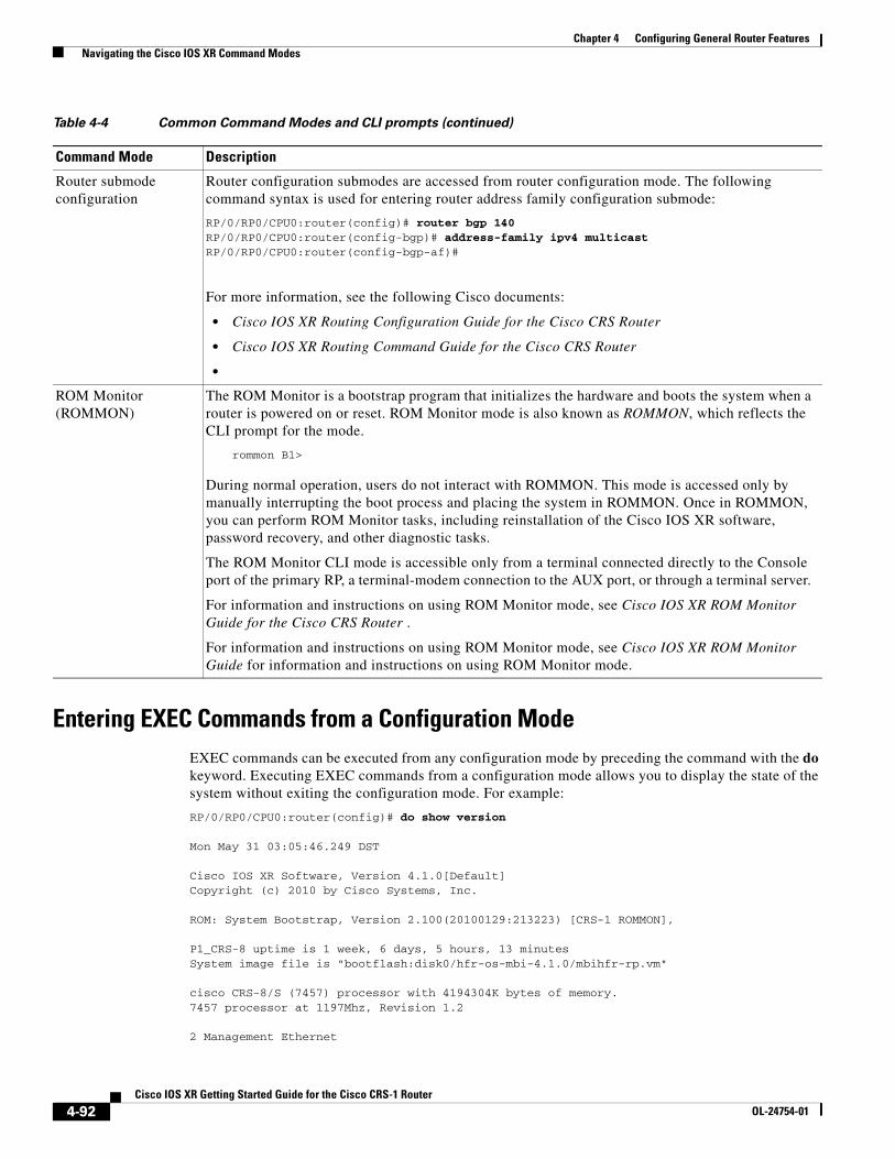
Entering EXEC Commands from a Configuration ModeEXEC commands can be executed from any configuration mode by preceding the command with the do keyword. Executing EXEC commands from a configuration mode allows you to display the state of the system without exiting the configuration mode. For example:
RP/0/RP0/CPU0:router(config)# do show version
Mon May 31 03:05:46.249 DST
Cisco IOS XR Software, Version 4.1.0[Default]Copyright (c) 2010 by Cisco Systems, Inc.
ROM: System Bootstrap, Version 2.100(20100129:213223) [CRS-1 ROMMON],
P1_CRS-8 uptime is 1 week, 6 days, 5 hours, 13 minutesSystem image file is "bootflash:disk0/hfr-os-mbi-4.1.0/mbihfr-rp.vm"
cisco CRS-8/S (7457) processor with 4194304K bytes of memory.7457 processor at 1197Mhz, Revision 1.2
2 Management Ethernet
Router submode configuration
Router configuration submodes are accessed from router configuration mode. The following command syntax is used for entering router address family configuration submode:
RP/0/RP0/CPU0:router(config)# router bgp 140RP/0/RP0/CPU0:router(config-bgp)# address-family ipv4 multicastRP/0/RP0/CPU0:router(config-bgp-af)#
For more information, see the following Cisco documents:
• Cisco IOS XR Routing Configuration Guide for the Cisco CRS Router
• Cisco IOS XR Routing Command Guide for the Cisco CRS Router
•
ROM Monitor (ROMMON)
The ROM Monitor is a bootstrap program that initializes the hardware and boots the system when a router is powered on or reset. ROM Monitor mode is also known as ROMMON, which reflects the CLI prompt for the mode.
rommon B1>
During normal operation, users do not interact with ROMMON. This mode is accessed only by manually interrupting the boot process and placing the system in ROMMON. Once in ROMMON, you can perform ROM Monitor tasks, including reinstallation of the Cisco IOS XR software, password recovery, and other diagnostic tasks.
The ROM Monitor CLI mode is accessible only from a terminal connected directly to the Console port of the primary RP, a terminal-modem connection to the AUX port, or through a terminal server.
For information and instructions on using ROM Monitor mode, see Cisco IOS XR ROM Monitor Guide for the Cisco CRS Router .
For information and instructions on using ROM Monitor mode, see Cisco IOS XR ROM Monitor Guide for information and instructions on using ROM Monitor mode.
Table 4-4 Common Command Modes and CLI prompts (continued)
Command Mode Description
4-92Cisco IOS XR Getting Started Guide for the Cisco CRS-1 Router
OL-24754-01
Chapter 4 Configuring General Router Features Navigating the Cisco IOS XR Command Modes
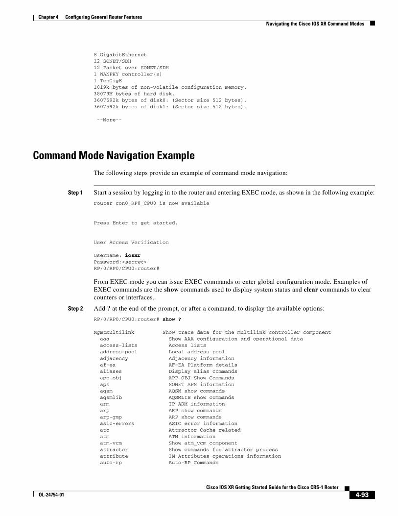
8 GigabitEthernet12 SONET/SDH12 Packet over SONET/SDH1 WANPHY controller(s)1 TenGigE1019k bytes of non-volatile configuration memory.38079M bytes of hard disk.3607592k bytes of disk0: (Sector size 512 bytes).3607592k bytes of disk1: (Sector size 512 bytes).
--More--
Command Mode Navigation ExampleThe following steps provide an example of command mode navigation:
Step 1 Start a session by logging in to the router and entering EXEC mode, as shown in the following example:
router con0_RP0_CPU0 is now available
Press Enter to get started.
User Access Verification
Username: iosxrPassword:<secret>RP/0/RP0/CPU0:router#
From EXEC mode you can issue EXEC commands or enter global configuration mode. Examples of EXEC commands are the show commands used to display system status and clear commands to clear counters or interfaces.
Step 2 Add ? at the end of the prompt, or after a command, to display the available options:
RP/0/RP0/CPU0:router# show ?
MgmtMultilink Show trace data for the multilink controller component aaa Show AAA configuration and operational data access-lists Access lists address-pool Local address pool adjacency Adjacency information af-ea AF-EA Platform details aliases Display alias commands app-obj APP-OBJ Show Commands aps SONET APS information aqsm AQSM show commands aqsmlib AQSMLIB show commands arm IP ARM information arp ARP show commands arp-gmp ARP show commands asic-errors ASIC error information atc Attractor Cache related atm ATM information atm-vcm Show atm_vcm component attractor Show commands for attractor process attribute IM Attributes operations information auto-rp Auto-RP Commands
4-93Cisco IOS XR Getting Started Guide for the Cisco CRS-1 Router
OL-24754-01
Chapter 4 Configuring General Router Features Managing Configuration Sessions
bcdl Show Bulk Content DownLoader information bfd BFD information --More--
Note The commands available depend on the router mode and your user group assignments.
Step 3 If you belong to a user group that has configuration privileges, you can place the router in the global configuration mode by entering the configure command:
RP/0/RP0/CPU0:router# configureRP/0/RP0/CPU0:router(config)#
Step 4 From global configuration mode, you can place the router in a configuration submode, such as interface configuration mode or a protocol-specific configuration mode.
In the following example, the router enters interface configuration mode and the user selects a POS interface for configuration. The command syntax is interface type rack/slot/module/port.
RP/0/RP0/CPU0:router(config)# interface POS 0/2/0/4RP/0/RP0/CPU0:router(config-if)#
The command mode prompt changes from (config) to (config-if) and you can now enter configuration commands for the specified interface.
Step 5 To exit interface configuration mode and return to global configuration mode, enter the exit command. To return to EXEC mode, enter the end command.
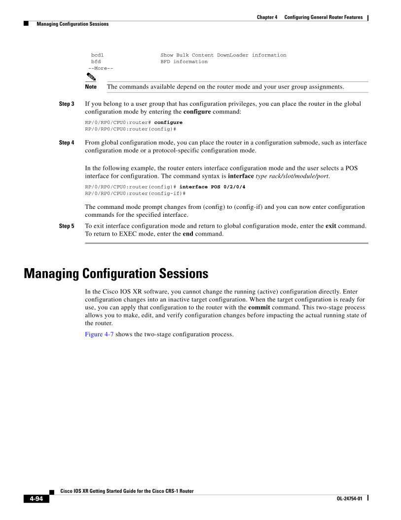
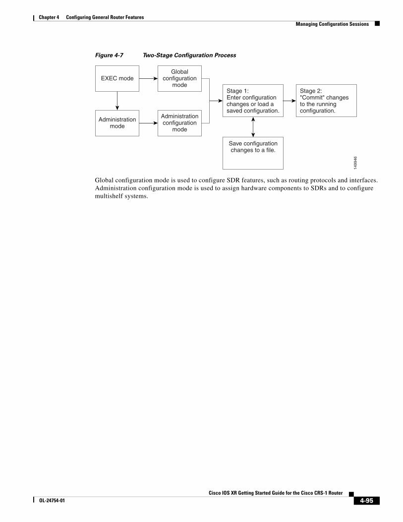
Managing Configuration SessionsIn the Cisco IOS XR software, you cannot change the running (active) configuration directly. Enter configuration changes into an inactive target configuration. When the target configuration is ready for use, you can apply that configuration to the router with the commit command. This two-stage process allows you to make, edit, and verify configuration changes before impacting the actual running state of the router.
Figure 4-7 shows the two-stage configuration process.
4-94Cisco IOS XR Getting Started Guide for the Cisco CRS-1 Router
OL-24754-01
Chapter 4 Configuring General Router Features Managing Configuration Sessions
Figure 4-7 Two-Stage Configuration Process
Global configuration mode is used to configure SDR features, such as routing protocols and interfaces. Administration configuration mode is used to assign hardware components to SDRs and to configure multishelf systems.
EXEC modeGlobal
configurationmode
Administrationmode
Administrationconfiguration
mode
Stage 1:Enter configurationchanges or load asaved configuration.
Save configurationchanges to a file.
Stage 2:"Commit" changesto the runningconfiguration.
1499
46
4-95Cisco IOS XR Getting Started Guide for the Cisco CRS-1 Router
OL-24754-01
Chapter 4 Configuring General Router Features Managing Configuration Sessions
The following sections describe the management options for configuration sessions:
• Displaying the Active Configuration Sessions, page 4-96
• Starting a Configuration Session, page 4-97
• Starting an Exclusive Configuration Session, page 4-98
• Displaying Configuration Details with show Commands, page 4-99
• Saving the Target Configuration to a File, page 4-105
• Loading the Target Configuration from a File, page 4-106
• Loading an Alternative Configuration at System Startup, page 4-106
• Clearing All Changes to a Target Configuration, page 4-106
• Committing Changes to the Running Configuration, page 4-107
• Reloading a Failed Configuration, page 4-109
• Exiting a Configuration Submode, page 4-109
• Returning Directly to Configuration Mode from a Submode, page 4-110
• Ending a Configuration Session, page 4-110
• Aborting a Configuration Session, page 4-110
• Configuring the SDR Hostname, page 4-111
• Configuring the Management Ethernet Interface, page 4-111
• Specifying the Management Ethernet Interface Name in CLI Commands, page 4-112
• Displaying the Available Management Ethernet Interfaces, page 4-112
• Configuring the Management Ethernet Interface, page 4-113
Displaying the Active Configuration SessionsBefore you start a configuration session, you should check if there are other configuration sessions in progress. More than one user can open a target configuration session at a time, allowing multiple users to work on separate target configurations.
The procedure for viewing the active configuration sessions depends on the type of configuration session. For administration configuration sessions, which assign hardware components in SDRs and multishelf systems, you must be in administration EXEC mode to view the active administration configuration sessions. For SDR configuration sessions, you must be in EXEC mode to view the active SDR configuration sessions.
To view the active administration configuration sessions, connect to the DSC and enter the show configuration sessions command in administration EXEC mode, as shown in the following example:
RP/0/RP0/CPU0:router# admin RP/0/RP0/CPU0:router(admin)# show configuration sessions
Session Line User Date Lock00000201-002180dd-00000000 vty0 cisco Thu Mar 16 14:47:08 2006
To view the active SDR configuration sessions, connect to the appropriate SDR and enter the show configuration sessions command in EXEC mode, as shown in the following example:
RP/0/RP0/CPU0:router# show configuration sessions
4-96Cisco IOS XR Getting Started Guide for the Cisco CRS-1 Router
OL-24754-01
Chapter 4 Configuring General Router Features Managing Configuration Sessions
Current Configuration Session Line User Date Lock00000201-002180dd-00000000 vty0 test Thu Mar 16 13:16:17 2006 00000201-001b307a-00000000 vty2 cisco Thu Mar 16 13:16:17 2006 *
If an asterisk (*) appears in the Lock column, the user is using an exclusive configuration session and you cannot start a configuration session until the exclusive configuration session closes. For more information, see the “Starting an Exclusive Configuration Session” section on page 4-98.
Note Configuration sessions for administration configuration and each SDR are managed independently. For example, if a user locks the administration configuration, you can still configure an SDR if other users have not locked a configuration session for that SDR.
Starting a Configuration SessionWhen you place the router in global configuration mode or administration configuration mode using the configure command, a new target configuration session is created. The target configuration allows you to enter, review, and verify configuration changes without impacting the running configuration.
Note The target configuration is not a copy of the running configuration. It has only the configuration commands entered during the target configuration session.
While in configuration mode, you can enter all Cisco IOS XR software commands supported in that configuration mode. Each command is added to the target configuration. You can view the target configuration by entering the show configuration command in configuration mode. The target configuration is not applied until you enter the commit command, as described in the “Committing Changes to the Running Configuration” section on page 4-107.
You can save target configurations to disk as nonactive configuration files. These saved files can be loaded, further modified, and committed at a later time. For more information, see the “Saving the Target Configuration to a File” section on page 4-105.
Examples
The following examples show how to manage configuration sessions:
• Simple Owner SDR Configuration: Example, page 4-97
• Simple Administration Configuration Session: Example, page 4-98
Simple Owner SDR Configuration: Example
The following example shows a simple owner SDR configuration session in which the target configuration is created and previewed in global configuration mode:
RP/0/RP0/CPU0:router # configure RP/0/RP0/CPU0:router(config)# interface POS 0/2/0/1 RP/0/RP0/CPU0:router(config-if)# description faq RP/0/RP0/CPU0:router(config-if)# ipv4 address 10.10.10.10 255.0.0.0 RP/0/RP0/CPU0:router(config-if)# show configuration
Building configuration.... interface POS0/0/0/1 description faq
4-97Cisco IOS XR Getting Started Guide for the Cisco CRS-1 Router
OL-24754-01
Chapter 4 Configuring General Router Features Managing Configuration Sessions
ipv4 address 10.10.10.10 255.0.0.0 end
Simple Administration Configuration Session: Example
The following example shows a simple administration configuration session in which the target configuration is created and previewed in administration configuration mode:
RP/0/RP0/CPU0:router# adminRP/0/RP0/CPU0:router(admin)# configureRP/0/RP0/CPU0:router(admin-config)# sdr testRP/0/RP0/CPU0:router(admin-config-sdr:test)# location 0/1/SPRP/0/RP0/CPU0:router(admin-config-sdr:test)# show configuration
Building configuration...sdr test location 0/1/SP !end
Starting an Exclusive Configuration SessionAn exclusive configuration session allows you to configure the administration configuration or an SDR and lock out all users from committing configuration changes until you are done. Other users can still create and modify a target configuration, but they cannot commit those changes to the running configuration until you exit your exclusive configuration session.
During regular configuration sessions, the running configuration is locked whenever a commit operation is being performed. This automatic locking ensures that each commit operation is completed before the next one begins. Other users receive an error message if they attempt to commit a target configuration while another commit operation is under way.
To start an exclusive configuration session for an SDR, connect to that SDR and enter the configure exclusive command:
RP/0/RP0/CPU0:router# configure exclusiveRP/0/RP0/CPU0:router(config)#
Note If the configuration is already locked by another user, the configure exclusive command fails. To view locked and unlocked configuration sessions, see the “Displaying the Active Configuration Sessions” section on page 4-96.
To start an exclusive configuration session for the administration configuration, connect to the DSC and enter the configure exclusive command in administration EXEC mode:
RP/0/RP0/CPU0:router# adminRP/0/RP0/CPU0:router(admin)# configure exclusiveRP/0/RP0/CPU0:router(admin-config)#
The running configuration is unlocked when the user who started the exclusive configuration session exits the configuration mode, as described in the “Ending a Configuration Session” section on page 4-110.
4-98Cisco IOS XR Getting Started Guide for the Cisco CRS-1 Router
OL-24754-01
Chapter 4 Configuring General Router Features Managing Configuration Sessions
Displaying Configuration Details with show CommandsThe following sections describe the following tasks:
• Displaying the Running Configuration, page 4-99
• Displaying a Sanitized Version of the Running Configuration, page 4-101
• Displaying the Target Configuration, page 4-103
• Displaying a Combined Target and Running Configuration, page 4-103
• Displaying Configuration Error Messages and Descriptions, page 4-104
• Displaying Configuration Error Messages Without Descriptions, page 4-105
• Displaying Configuration Error Messages Produced While Loading a Configuration, page 4-105
Displaying the Running Configuration
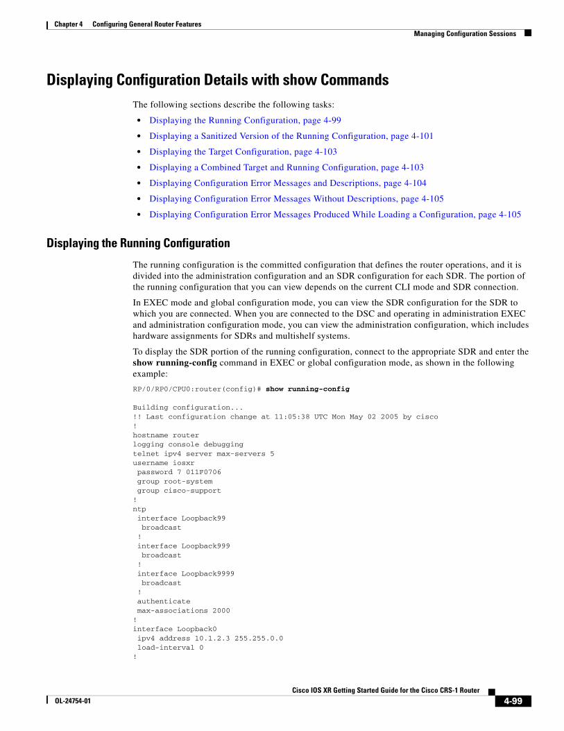
The running configuration is the committed configuration that defines the router operations, and it is divided into the administration configuration and an SDR configuration for each SDR. The portion of the running configuration that you can view depends on the current CLI mode and SDR connection.
In EXEC mode and global configuration mode, you can view the SDR configuration for the SDR to which you are connected. When you are connected to the DSC and operating in administration EXEC and administration configuration mode, you can view the administration configuration, which includes hardware assignments for SDRs and multishelf systems.
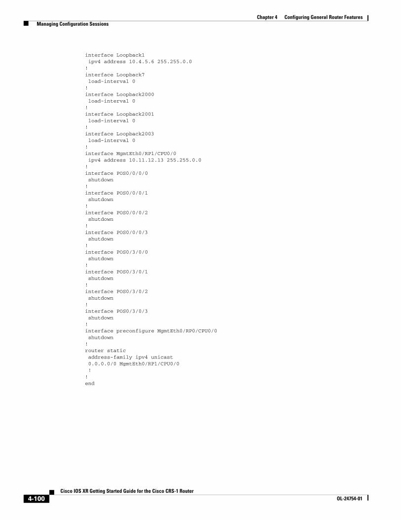
To display the SDR portion of the running configuration, connect to the appropriate SDR and enter the show running-config command in EXEC or global configuration mode, as shown in the following example:
RP/0/RP0/CPU0:router(config)# show running-config
Building configuration...!! Last configuration change at 11:05:38 UTC Mon May 02 2005 by cisco!hostname routerlogging console debuggingtelnet ipv4 server max-servers 5username iosxr password 7 011F0706 group root-system group cisco-support!ntp interface Loopback99 broadcast ! interface Loopback999 broadcast ! interface Loopback9999 broadcast ! authenticate max-associations 2000!interface Loopback0 ipv4 address 10.1.2.3 255.255.0.0 load-interval 0!
4-99Cisco IOS XR Getting Started Guide for the Cisco CRS-1 Router
OL-24754-01
Chapter 4 Configuring General Router Features Managing Configuration Sessions
interface Loopback1 ipv4 address 10.4.5.6 255.255.0.0!interface Loopback7 load-interval 0!interface Loopback2000 load-interval 0!interface Loopback2001 load-interval 0!interface Loopback2003 load-interval 0!interface MgmtEth0/RP1/CPU0/0 ipv4 address 10.11.12.13 255.255.0.0!interface POS0/0/0/0 shutdown!interface POS0/0/0/1 shutdown!interface POS0/0/0/2 shutdown!interface POS0/0/0/3 shutdown!interface POS0/3/0/0 shutdown!interface POS0/3/0/1 shutdown!interface POS0/3/0/2 shutdown!interface POS0/3/0/3 shutdown!interface preconfigure MgmtEth0/RP0/CPU0/0 shutdown!router static address-family ipv4 unicast 0.0.0.0/0 MgmtEth0/RP1/CPU0/0 !!end
4-100Cisco IOS XR Getting Started Guide for the Cisco CRS-1 Router
OL-24754-01
Chapter 4 Configuring General Router Features Managing Configuration Sessions
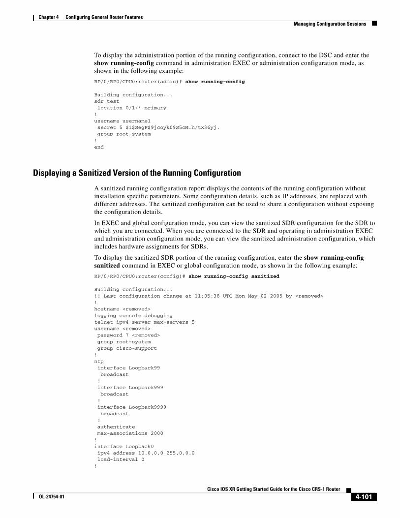
To display the administration portion of the running configuration, connect to the DSC and enter the show running-config command in administration EXEC or administration configuration mode, as shown in the following example:
RP/0/RP0/CPU0:router(admin)# show running-config
Building configuration...sdr test location 0/1/* primary !username username1 secret 5 $1$SegP$9jcoyk09S5cM.h/tX36yj. group root-system !end
Displaying a Sanitized Version of the Running Configuration
A sanitized running configuration report displays the contents of the running configuration without installation specific parameters. Some configuration details, such as IP addresses, are replaced with different addresses. The sanitized configuration can be used to share a configuration without exposing the configuration details.
In EXEC and global configuration mode, you can view the sanitized SDR configuration for the SDR to which you are connected. When you are connected to the SDR and operating in administration EXEC and administration configuration mode, you can view the sanitized administration configuration, which includes hardware assignments for SDRs.
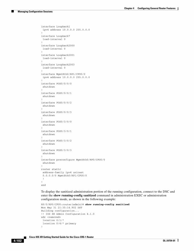
To display the sanitized SDR portion of the running configuration, enter the show running-config sanitized command in EXEC or global configuration mode, as shown in the following example:
RP/0/RP0/CPU0:router(config)# show running-config sanitized
Building configuration...!! Last configuration change at 11:05:38 UTC Mon May 02 2005 by <removed>!hostname <removed>logging console debuggingtelnet ipv4 server max-servers 5username <removed> password 7 <removed> group root-system group cisco-support!ntp interface Loopback99 broadcast ! interface Loopback999 broadcast ! interface Loopback9999 broadcast ! authenticate max-associations 2000!interface Loopback0 ipv4 address 10.0.0.0 255.0.0.0 load-interval 0!
4-101Cisco IOS XR Getting Started Guide for the Cisco CRS-1 Router
OL-24754-01
Chapter 4 Configuring General Router Features Managing Configuration Sessions
interface Loopback1 ipv4 address 10.0.0.0 255.0.0.0!interface Loopback7 load-interval 0!interface Loopback2000 load-interval 0!interface Loopback2001 load-interval 0!interface Loopback2003 load-interval 0!interface MgmtEth0/RP1/CPU0/0 ipv4 address 10.0.0.0 255.0.0.0!interface POS0/0/0/0 shutdown!interface POS0/0/0/1 shutdown!interface POS0/0/0/2 shutdown!interface POS0/0/0/3 shutdown!interface POS0/3/0/0 shutdown!interface POS0/3/0/1 shutdown!interface POS0/3/0/2 shutdown!interface POS0/3/0/3 shutdown!interface preconfigure MgmtEth0/RP0/CPU0/0 shutdown!router static address-family ipv4 unicast 0.0.0.0/0 MgmtEth0/RP1/CPU0/0 !!end
To display the sanitized administration portion of the running configuration, connect to the DSC and enter the show running-config sanitized command in administration EXEC or administration configuration mode, as shown in the following example:
RP/0/RP0/CPU0:router(admin)# show running-config sanitizedMon May 31 21:35:14.902 DSTBuilding configuration...!! IOS XR Admin Configuration 4.1.0sdr <removed> location 0/1/* location 0/4/* primary!
4-102Cisco IOS XR Getting Started Guide for the Cisco CRS-1 Router
OL-24754-01
Chapter 4 Configuring General Router Features Managing Configuration Sessions
username <removed> group root-system group cisco-support secret 5 <removed>!end
Displaying the Target Configuration
The target configuration includes the configuration changes that have been entered but not yet committed. These changes are not yet part of the running configuration.
You can view the target configuration in global configuration and administration configuration modes. You cannot view the target configuration in EXEC modes because the target configuration must be committed or abandoned before returning to EXEC or administration EXEC mode.
To display the target configuration changes you have entered for an SDR, enter the show configuration command in global configuration mode or in any submode, as shown in the following example:
RP/0/RP0/CPU0:router(config-if)# show configuration
Building configuration... interface POS0/3/0/3 description faq ipv4 address 10.1.1.1 255.0.0.0 end
To display the target administration configuration changes you have entered, enter the show configuration command in administration configuration mode or in any submode, as shown in the following example:
RP/0/RP0/CPU0:router(admin-config-sdr:test)# show configuration
Building configuration...sdr test location 0/1/* primary !end
Displaying a Combined Target and Running Configuration
Although the target and running configurations remain separate until the target configuration is committed, you can preview the combined target and running configuration without committing the changes. The combined configuration shows what the new running configuration will look like after the changes from the target configuration are committed. It does not represent the actual running configuration.
You can preview the combined configuration in global configuration and administration configuration modes. You cannot preview the combined configuration in EXEC modes because the target configuration must be committed or abandoned before returning to EXEC or administration EXEC mode.
To display the combined target and running configuration, enter the show configuration merge command in any configuration mode.
Note The merge option does not appear in command help until the target configuration contains at least one configuration change.
4-103Cisco IOS XR Getting Started Guide for the Cisco CRS-1 Router
OL-24754-01
Chapter 4 Configuring General Router Features Managing Configuration Sessions
The following example shows how to display the active SDR configuration (show running-config), configure an interface, and display the merged configuration:
RP/0/RP0/CPU0:router# show running-config
Building configuration... !! Last configuration change at 16:52:49 UTC Sun March 10 2004 by cisco ! hostname router shutdown end
RP/0/RP0/CPU0:router# configure RP/0/RP0/CPU0:router(config)# interface POS 0/3/0/3 RP/0/RP0/CPU0:router(config-if)# description faq RP/0/RP0/CPU0:router(config-if)# ipv4 address 10.1.1.1 255.0.0.0
RP/0/RP0/CPU0:router(config)# show configuration merge Building configuration... !! Last configuration change at 16:52:49 UTC Sun March 10 2004 by cisco ! hostname router interface POS0/3/0/3 description faq ipv4 address 10.1.1.1 255.0.0.0 shutdown end
Displaying Configuration Error Messages and Descriptions
Configuration changes are automatically verified during the commit operation, and a message appears if one or more configuration entry fails. To display an error message and description for a failed configuration, enter the show configuration failed command.
Note You can view configuration errors only during the current configuration session. If you exit configuration mode after the commit operation, the configuration error information is lost.
In the following example, an error is introduced in global configuration mode and the error information appears after the commit operation fails:
RP/0/RP0/CPU0:router# configureRP/0/RP0/CPU0:router(config)# taskgroup alrRP/0/RP0/CPU0:router(config-tg)# description this is a test of an invalid taskgroupRP/0/RP0/CPU0:router(config-tg)# commit
% Failed to commit one or more configuration items. Please use 'show configuration failed' to view the errors
RP/0/RP0/CPU0:router(config-tg)# show configuration failed
!! CONFIGURATION FAILED DUE TO SEMANTIC ERRORStaskgroup alr!!% Usergroup/Taskgroup names cannot be taskid names!
4-104Cisco IOS XR Getting Started Guide for the Cisco CRS-1 Router
OL-24754-01
Chapter 4 Configuring General Router Features Managing Configuration Sessions
Displaying Configuration Error Messages Without Descriptions
Configuration changes are automatically verified during the commit operation, and a message appears if one or more configuration entry fails. To display only the error message (without a description) for a failed configuration, enter the show configuration failed noerror command, as shown in the following example:
RP/0/RP0/CPU0:router(config-tg)# show configuration failed noerror
!! CONFIGURATION FAILED DUE TO SEMANTIC ERRORStaskgroup alr!
Note You can view configuration errors only during the current configuration session. If you exit configuration mode after the commit operation, the configuration error information is lost.
Displaying Configuration Error Messages Produced While Loading a Configuration
To display any syntax errors found in a configuration loaded with the load command, enter the show configuration failed load command.
Saving the Target Configuration to a FileTarget configurations can be saved to a separate file without committing them to the running configuration. Target configuration files can then be loaded at a later time and further modified or committed.
To save the configuration changes in the target configuration to a file, enter the save configuration device: command. Replace the device argument with the name of the device on which you want to store the file (for example, disk0). After you enter this command, the router prompts you to enter a filename. If you enter only a filename, the file is stored in the root directory of the device. To store the file in a directory, enter the directory path and filename when prompted. We recommend that you specify the cfg file extension for easy identification. This suffix is not required, but it can help locate target configuration files, for example:
myconfig.cfg
The following example shows a target configuration file saved to the usr/cisco directory of disk0:
RP/0/RP1/CPU0:router(admin-config)# save configuration disk0:
Mon May 31 21:52:13.237 DSTDestination file name (control-c to abort): [/running-config]?/usr/cisco/test.cfgBuilding configuration.1 lines built in 1 second[OK]
You can also save a configuration to a file using the show configuration | file filename command.
RP/0/RP1/CPU0:router(config)#show configuration | file abc.cfgThu Jul 22 23:03:04.722 DSTBuilding configuration...
[OK]
4-105Cisco IOS XR Getting Started Guide for the Cisco CRS-1 Router
OL-24754-01
Chapter 4 Configuring General Router Features Managing Configuration Sessions
Loading the Target Configuration from a FileTo populate the target configuration with the contents of a previously saved configuration file, go to global configuration or administration configuration mode and enter the load filename command. Consider the following when entering the filename argument:
• Specifies the configuration file to be loaded into the target configuration.
• If the full path of the file is not specified, the router attempts to load the file from the root directory on the device.
The following example shows a target configuration file loaded into the current configuration session. The current configuration session is populated with the contents of the file.
RP/0/RP1/CPU0:router(config)# load disk0:/usr/cisco/test.cfg
Loading.77 bytes parsed in 1 sec (76)bytes/sec
Loading an Alternative Configuration at System StartupWhen a router is reset or powered on, the last running configuration is loaded and used to operate the router.
You can load an alternative configuration during system boot. For information and instructions on this process, see Cisco IOS XR ROM Monitor Guide for the Cisco CRS Router .
Clearing All Changes to a Target ConfigurationTo clear changes made to the target configuration without terminating the configuration session, enter the clear command in global configuration mode or administration configuration mode. This command deletes any configuration changes that have not been committed.
In the following example, the user configures an interface but does not commit it. After reviewing the changes to the target configuration with the show configuration command, the user decides to remove the changes and start over by entering the clear command:
RP/0/RP0/CPU0:router# configure RP/0/RP0/CPU0:router(config)# interface POS 0/3/0/1 RP/0/RP0/CPU0:router(config-if)# description this is my interface RP/0/RP0/CPU0:router(config-if)# ipv4 address 10.1.1.1 255.0.0.0 RP/0/RP0/CPU0:router(config-if)# shutdown RP/0/RP0/CPU0:router(config-if)# exit
RP/0/RP0/CPU0:router(config)# show configuration
Building configuration... interface POS0/3/0/1 description this is my interface ipv4 address 10.1.1.1 255.0.0.0 shutdown end
RP/0/RP0/CPU0:router(config)# clear RP/0/RP0/CPU0:router(config)# show configurationBuilding configuration... end
4-106Cisco IOS XR Getting Started Guide for the Cisco CRS-1 Router
OL-24754-01
Chapter 4 Configuring General Router Features Managing Configuration Sessions
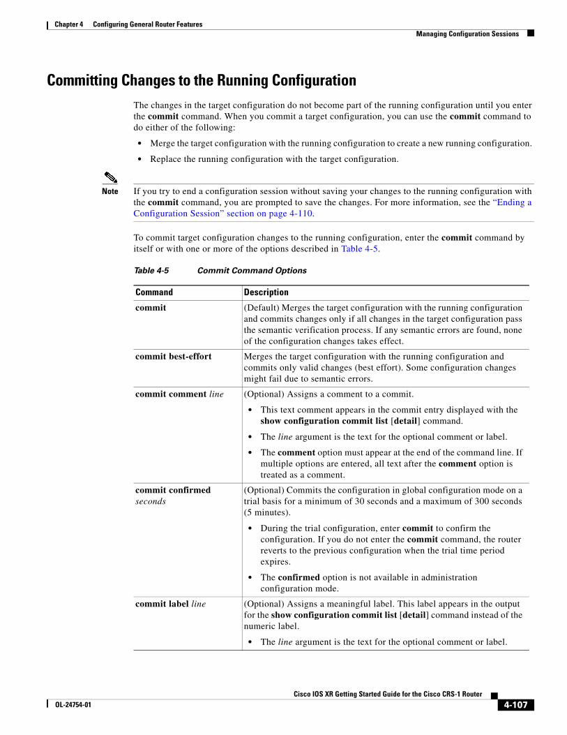
Committing Changes to the Running ConfigurationThe changes in the target configuration do not become part of the running configuration until you enter the commit command. When you commit a target configuration, you can use the commit command to do either of the following:
• Merge the target configuration with the running configuration to create a new running configuration.
• Replace the running configuration with the target configuration.
Note If you try to end a configuration session without saving your changes to the running configuration with the commit command, you are prompted to save the changes. For more information, see the “Ending a Configuration Session” section on page 4-110.
To commit target configuration changes to the running configuration, enter the commit command by itself or with one or more of the options described in Table 4-5.
Table 4-5 Commit Command Options
Command Description
commit (Default) Merges the target configuration with the running configuration and commits changes only if all changes in the target configuration pass the semantic verification process. If any semantic errors are found, none of the configuration changes takes effect.
commit best-effort Merges the target configuration with the running configuration and commits only valid changes (best effort). Some configuration changes might fail due to semantic errors.
commit comment line (Optional) Assigns a comment to a commit.
• This text comment appears in the commit entry displayed with the show configuration commit list [detail] command.
• The line argument is the text for the optional comment or label.
• The comment option must appear at the end of the command line. If multiple options are entered, all text after the comment option is treated as a comment.
commit confirmed seconds
(Optional) Commits the configuration in global configuration mode on a trial basis for a minimum of 30 seconds and a maximum of 300 seconds (5 minutes).
• During the trial configuration, enter commit to confirm the configuration. If you do not enter the commit command, the router reverts to the previous configuration when the trial time period expires.
• The confirmed option is not available in administration configuration mode.
commit label line (Optional) Assigns a meaningful label. This label appears in the output for the show configuration commit list [detail] command instead of the numeric label.
• The line argument is the text for the optional comment or label.
4-107Cisco IOS XR Getting Started Guide for the Cisco CRS-1 Router
OL-24754-01
Chapter 4 Configuring General Router Features Managing Configuration Sessions
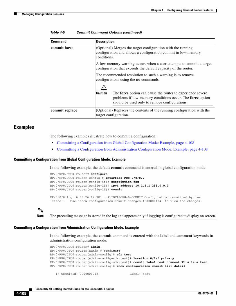
Examples
The following examples illustrate how to commit a configuration:
• Committing a Configuration from Global Configuration Mode: Example, page 4-108
• Committing a Configuration from Administration Configuration Mode: Example, page 4-108
Committing a Configuration from Global Configuration Mode: Example
In the following example, the default commit command is entered in global configuration mode:
RP/0/RP0/CPU0:router# configure RP/0/RP0/CPU0:router(config)# interface POS 0/0/0/2RP/0/RP0/CPU0:router(config-if)# description faq RP/0/RP0/CPU0:router(config-if)# ipv4 address 10.1.1.1 255.0.0.0 RP/0/RP0/CPU0:router(config-if)# commit
RP/0/0/0:Aug 6 09:26:17.781 : %LIBTARCFG-6-COMMIT Configuration committed by user ‘cisco'. Use 'show configuration commit changes 1000000124' to view the changes.
Note The preceding message is stored in the log and appears only if logging is configured to display on screen.
Committing a Configuration from Administration Configuration Mode: Example
In the following example, the commit command is entered with the label and comment keywords in administration configuration mode:
RP/0/RP0/CPU0:router# adminRP/0/RP0/CPU0:router(admin)# configure RP/0/RP0/CPU0:router(admin-config)# sdr testRP/0/RP0/CPU0:router(admin-config-sdr:test)# location 0/1/* primaryRP/0/RP0/CPU0:router(admin-config-sdr:test)# commit label test comment This is a testRP/0/RP0/CPU0:router(admin-config)# show configuration commit list detail
1) CommitId: 2000000018 Label: test
commit force (Optional) Merges the target configuration with the running configuration and allows a configuration commit in low-memory conditions.
A low-memory warning occurs when a user attempts to commit a target configuration that exceeds the default capacity of the router.
The recommended resolution to such a warning is to remove configurations using the no commands.
Caution The force option can cause the router to experience severe problems if low-memory conditions occur. The force option should be used only to remove configurations.
commit replace (Optional) Replaces the contents of the running configuration with the target configuration.
Table 4-5 Commit Command Options (continued)
Command Description
4-108Cisco IOS XR Getting Started Guide for the Cisco CRS-1 Router
OL-24754-01
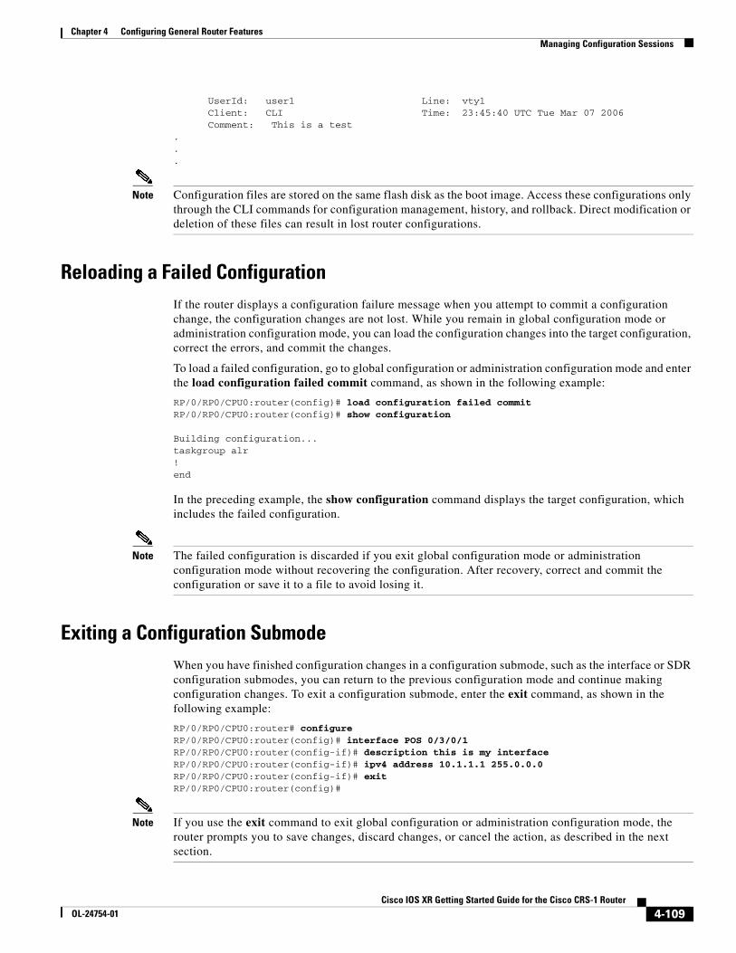
Chapter 4 Configuring General Router Features Managing Configuration Sessions
UserId: user1 Line: vty1 Client: CLI Time: 23:45:40 UTC Tue Mar 07 2006 Comment: This is a test ...
Note Configuration files are stored on the same flash disk as the boot image. Access these configurations only through the CLI commands for configuration management, history, and rollback. Direct modification or deletion of these files can result in lost router configurations.
Reloading a Failed ConfigurationIf the router displays a configuration failure message when you attempt to commit a configuration change, the configuration changes are not lost. While you remain in global configuration mode or administration configuration mode, you can load the configuration changes into the target configuration, correct the errors, and commit the changes.
To load a failed configuration, go to global configuration or administration configuration mode and enter the load configuration failed commit command, as shown in the following example:
RP/0/RP0/CPU0:router(config)# load configuration failed commitRP/0/RP0/CPU0:router(config)# show configuration
Building configuration...taskgroup alr!end
In the preceding example, the show configuration command displays the target configuration, which includes the failed configuration.
Note The failed configuration is discarded if you exit global configuration mode or administration configuration mode without recovering the configuration. After recovery, correct and commit the configuration or save it to a file to avoid losing it.
Exiting a Configuration SubmodeWhen you have finished configuration changes in a configuration submode, such as the interface or SDR configuration submodes, you can return to the previous configuration mode and continue making configuration changes. To exit a configuration submode, enter the exit command, as shown in the following example:
RP/0/RP0/CPU0:router# configure RP/0/RP0/CPU0:router(config)# interface POS 0/3/0/1 RP/0/RP0/CPU0:router(config-if)# description this is my interface RP/0/RP0/CPU0:router(config-if)# ipv4 address 10.1.1.1 255.0.0.0 RP/0/RP0/CPU0:router(config-if)# exit RP/0/RP0/CPU0:router(config)#
Note If you use the exit command to exit global configuration or administration configuration mode, the router prompts you to save changes, discard changes, or cancel the action, as described in the next section.
4-109Cisco IOS XR Getting Started Guide for the Cisco CRS-1 Router
OL-24754-01
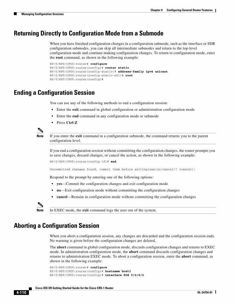
Chapter 4 Configuring General Router Features Managing Configuration Sessions
Returning Directly to Configuration Mode from a SubmodeWhen you have finished configuration changes in a configuration submode, such as the interface or SDR configuration submodes, you can skip all intermediate submodes and return to the top-level configuration mode and continue making configuration changes. To return to configuration mode, enter the root command, as shown in the following example:
RP/0/RP0/CPU0:router# configureRP/0/RP0/CPU0:router(config)# router static RP/0/RP0/CPU0:router(config-static)# address-family ipv4 unicast RP/0/RP0/CPU0:router(config-static-afi)# rootRP/0/RP0/CPU0:router(config)#
Ending a Configuration SessionYou can use any of the following methods to end a configuration session:
• Enter the exit command in global configuration or administration configuration mode
• Enter the end command in any configuration mode or submode
• Press Ctrl-Z
Note If you enter the exit command in a configuration submode, the command returns you to the parent configuration level.
If you end a configuration session without committing the configuration changes, the router prompts you to save changes, discard changes, or cancel the action, as shown in the following example:
RP/0/RP0/CPU0:router(config-if)# end
Uncommitted changes found, commit them before exiting(yes/no/cancel)? [cancel]:
Respond to the prompt by entering one of the following options:
• yes—Commit the configuration changes and exit configuration mode
• no—Exit configuration mode without committing the configuration changes
• cancel—Remain in configuration mode without committing the configuration changes
Note In EXEC mode, the exit command logs the user out of the system.
Aborting a Configuration SessionWhen you abort a configuration session, any changes are discarded and the configuration session ends. No warning is given before the configuration changes are deleted.
The abort command in global configuration mode, discards configuration changes and returns to EXEC mode. In administration configuration mode, the abort command discards configuration changes and returns to administration EXEC mode. To abort a configuration session, enter the abort command, as shown in the following example:
RP/0/RP0/CPU0:router# configureRP/0/RP0/CPU0:router(config)# hostname host1 RP/0/RP0/CPU0:router(config)# interface POS 0/2/0/2
4-110Cisco IOS XR Getting Started Guide for the Cisco CRS-1 Router
OL-24754-01
Chapter 4 Configuring General Router Features Configuring the SDR Hostname
RP/0/RP0/CPU0:router(config-if)# description this is my interface RP/0/RP0/CPU0:router(config-if)# ipv4 address 10.1.1.1 255.0.0.0 RP/0/RP0/CPU0:router(config-if)# shutdown RP/0/RP0/CPU0:router(config-if)# abort RP/0/RP0/CPU0:router#
Configuring the SDR HostnameThe hostname identifies an SDR on the network. Although devices can be uniquely identified by their Layer 2 and Layer 3 addresses (such as an IP address), it is often simpler to remember network devices by an alphanumeric “hostname.” This name is used in the CLI prompt and default configuration filenames and to identify the SDR on the network.
To configure the hostname, enter the hostname command with the SDR name as shown in the following example:
RP/0/RP0/CPU0:router# configureRP/0/RP0/CPU0:router(config)# hostname SDR_SJRP/0/RP0/CPU0:router(config)# commit
RP/0/RP0/CPU0:Apr 7 00:07:33.246 : config[65669]: %LIBTARCFG-6-COMMIT : Configuration committed by user 'user_a'. Use 'show configuration commit changes 1000000067' to view the changes.RP/0/RP0/CPU0:SDR_SJ(config)#
The preceding example sets the SDR name to SDR_SJ.
Note No blanks or spaces are permitted as part of a name. Do not expect case to be preserved. Uppercase and lowercase characters look the same to many Internet software applications. It may seem appropriate to capitalize a name the same way you might if you were writing, but conventions dictate that computer names appear all lowercase. For more information, see RFC 1178, Choosing a Name for Your Computer.
Configuring the Management Ethernet InterfaceThe Management Ethernet interface on the RPs is used to connect the router to a network for remote management using a Telnet client, the Simple Network Management Protocol (SNMP), or other management agents. The following sections provide information on the Management Ethernet interface:
• Specifying the Management Ethernet Interface Name in CLI Commands, page 4-112
• Displaying the Available Management Ethernet Interfaces, page 4-112
• Configuring the Management Ethernet Interface, page 4-113
4-111Cisco IOS XR Getting Started Guide for the Cisco CRS-1 Router
OL-24754-01
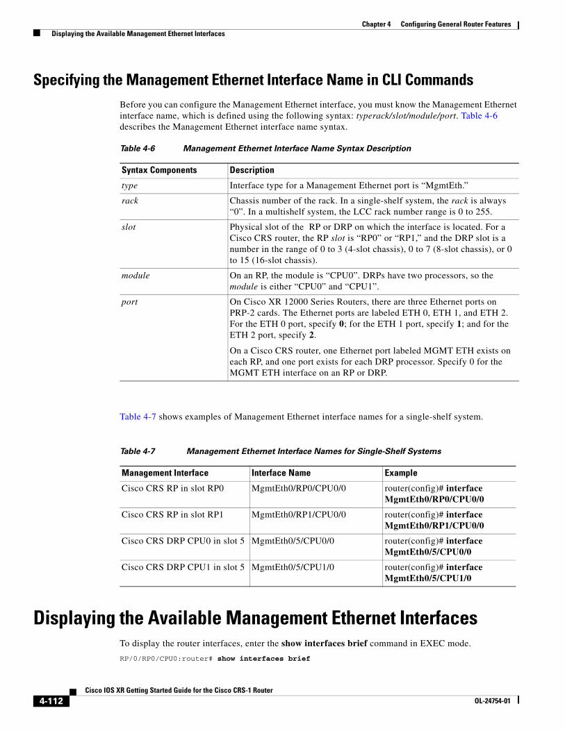
Chapter 4 Configuring General Router Features Displaying the Available Management Ethernet Interfaces
Specifying the Management Ethernet Interface Name in CLI CommandsBefore you can configure the Management Ethernet interface, you must know the Management Ethernet interface name, which is defined using the following syntax: typerack/slot/module/port. Table 4-6 describes the Management Ethernet interface name syntax.
Table 4-7 shows examples of Management Ethernet interface names for a single-shelf system.
Displaying the Available Management Ethernet Interfaces To display the router interfaces, enter the show interfaces brief command in EXEC mode.
RP/0/RP0/CPU0:router# show interfaces brief
Table 4-6 Management Ethernet Interface Name Syntax Description
Syntax Components Description
type Interface type for a Management Ethernet port is “MgmtEth.”
rack Chassis number of the rack. In a single-shelf system, the rack is always “0”. In a multishelf system, the LCC rack number range is 0 to 255.
slot Physical slot of the RP or DRP on which the interface is located. For a Cisco CRS router, the RP slot is “RP0” or “RP1,” and the DRP slot is a number in the range of 0 to 3 (4-slot chassis), 0 to 7 (8-slot chassis), or 0 to 15 (16-slot chassis).
module On an RP, the module is “CPU0”. DRPs have two processors, so the module is either “CPU0” and “CPU1”.
port On Cisco XR 12000 Series Routers, there are three Ethernet ports on PRP-2 cards. The Ethernet ports are labeled ETH 0, ETH 1, and ETH 2. For the ETH 0 port, specify 0; for the ETH 1 port, specify 1; and for the ETH 2 port, specify 2.
On a Cisco CRS router, one Ethernet port labeled MGMT ETH exists on each RP, and one port exists for each DRP processor. Specify 0 for the MGMT ETH interface on an RP or DRP.
Table 4-7 Management Ethernet Interface Names for Single-Shelf Systems
Management Interface Interface Name Example
Cisco CRS RP in slot RP0 MgmtEth0/RP0/CPU0/0 router(config)# interface MgmtEth0/RP0/CPU0/0
Cisco CRS RP in slot RP1 MgmtEth0/RP1/CPU0/0 router(config)# interface MgmtEth0/RP1/CPU0/0
Cisco CRS DRP CPU0 in slot 5 MgmtEth0/5/CPU0/0 router(config)# interface MgmtEth0/5/CPU0/0
Cisco CRS DRP CPU1 in slot 5 MgmtEth0/5/CPU1/0 router(config)# interface MgmtEth0/5/CPU1/0
4-112Cisco IOS XR Getting Started Guide for the Cisco CRS-1 Router
OL-24754-01
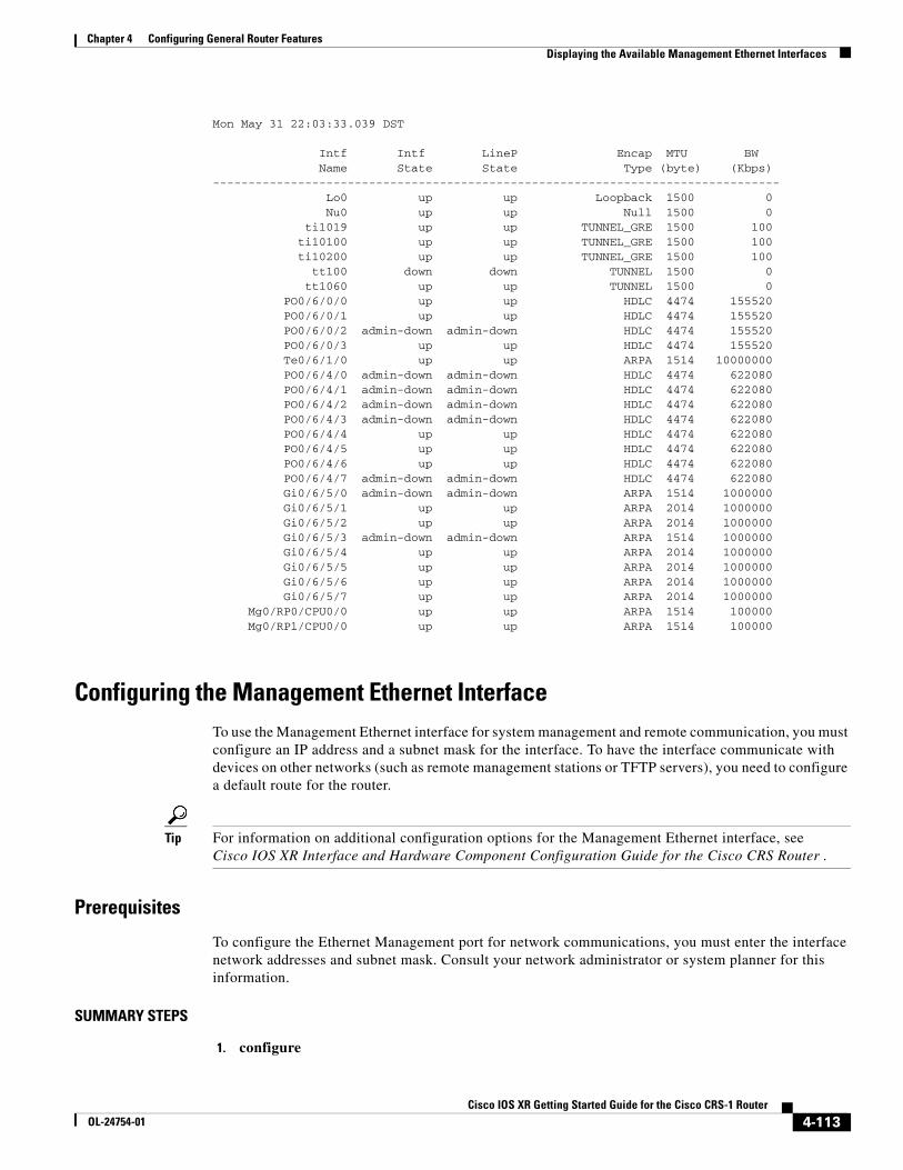
Chapter 4 Configuring General Router Features Displaying the Available Management Ethernet Interfaces
Mon May 31 22:03:33.039 DST
Intf Intf LineP Encap MTU BW Name State State Type (byte) (Kbps)-------------------------------------------------------------------------------- Lo0 up up Loopback 1500 0 Nu0 up up Null 1500 0 ti1019 up up TUNNEL_GRE 1500 100 ti10100 up up TUNNEL_GRE 1500 100 ti10200 up up TUNNEL_GRE 1500 100 tt100 down down TUNNEL 1500 0 tt1060 up up TUNNEL 1500 0 PO0/6/0/0 up up HDLC 4474 155520 PO0/6/0/1 up up HDLC 4474 155520 PO0/6/0/2 admin-down admin-down HDLC 4474 155520 PO0/6/0/3 up up HDLC 4474 155520 Te0/6/1/0 up up ARPA 1514 10000000 PO0/6/4/0 admin-down admin-down HDLC 4474 622080 PO0/6/4/1 admin-down admin-down HDLC 4474 622080 PO0/6/4/2 admin-down admin-down HDLC 4474 622080 PO0/6/4/3 admin-down admin-down HDLC 4474 622080 PO0/6/4/4 up up HDLC 4474 622080 PO0/6/4/5 up up HDLC 4474 622080 PO0/6/4/6 up up HDLC 4474 622080 PO0/6/4/7 admin-down admin-down HDLC 4474 622080 Gi0/6/5/0 admin-down admin-down ARPA 1514 1000000 Gi0/6/5/1 up up ARPA 2014 1000000 Gi0/6/5/2 up up ARPA 2014 1000000 Gi0/6/5/3 admin-down admin-down ARPA 1514 1000000 Gi0/6/5/4 up up ARPA 2014 1000000 Gi0/6/5/5 up up ARPA 2014 1000000 Gi0/6/5/6 up up ARPA 2014 1000000 Gi0/6/5/7 up up ARPA 2014 1000000 Mg0/RP0/CPU0/0 up up ARPA 1514 100000 Mg0/RP1/CPU0/0 up up ARPA 1514 100000
Configuring the Management Ethernet InterfaceTo use the Management Ethernet interface for system management and remote communication, you must configure an IP address and a subnet mask for the interface. To have the interface communicate with devices on other networks (such as remote management stations or TFTP servers), you need to configure a default route for the router.
Tip For information on additional configuration options for the Management Ethernet interface, see Cisco IOS XR Interface and Hardware Component Configuration Guide for the Cisco CRS Router .
Prerequisites
To configure the Ethernet Management port for network communications, you must enter the interface network addresses and subnet mask. Consult your network administrator or system planner for this information.
SUMMARY STEPS
1. configure
4-113Cisco IOS XR Getting Started Guide for the Cisco CRS-1 Router
OL-24754-01
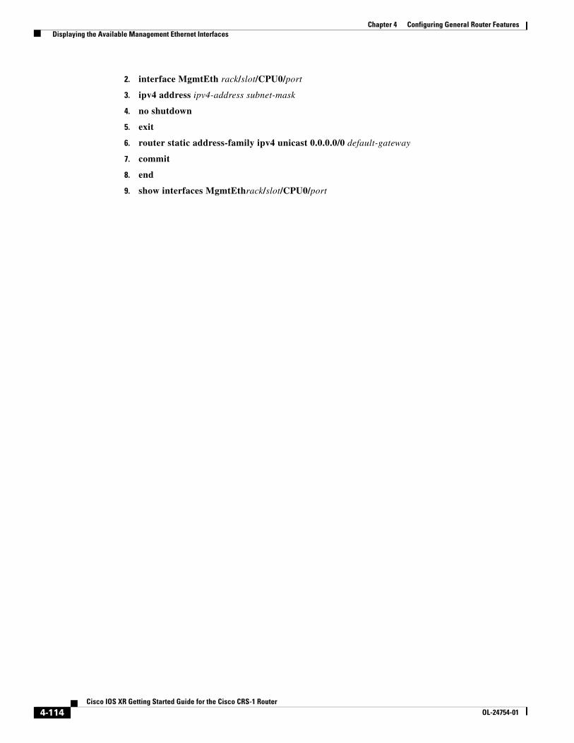
Chapter 4 Configuring General Router Features Displaying the Available Management Ethernet Interfaces
2. interface MgmtEth rack/slot/CPU0/port
3. ipv4 address ipv4-address subnet-mask
4. no shutdown
5. exit
6. router static address-family ipv4 unicast 0.0.0.0/0 default-gateway
7. commit
8. end
9. show interfaces MgmtEthrack/slot/CPU0/port
4-114Cisco IOS XR Getting Started Guide for the Cisco CRS-1 Router
OL-24754-01
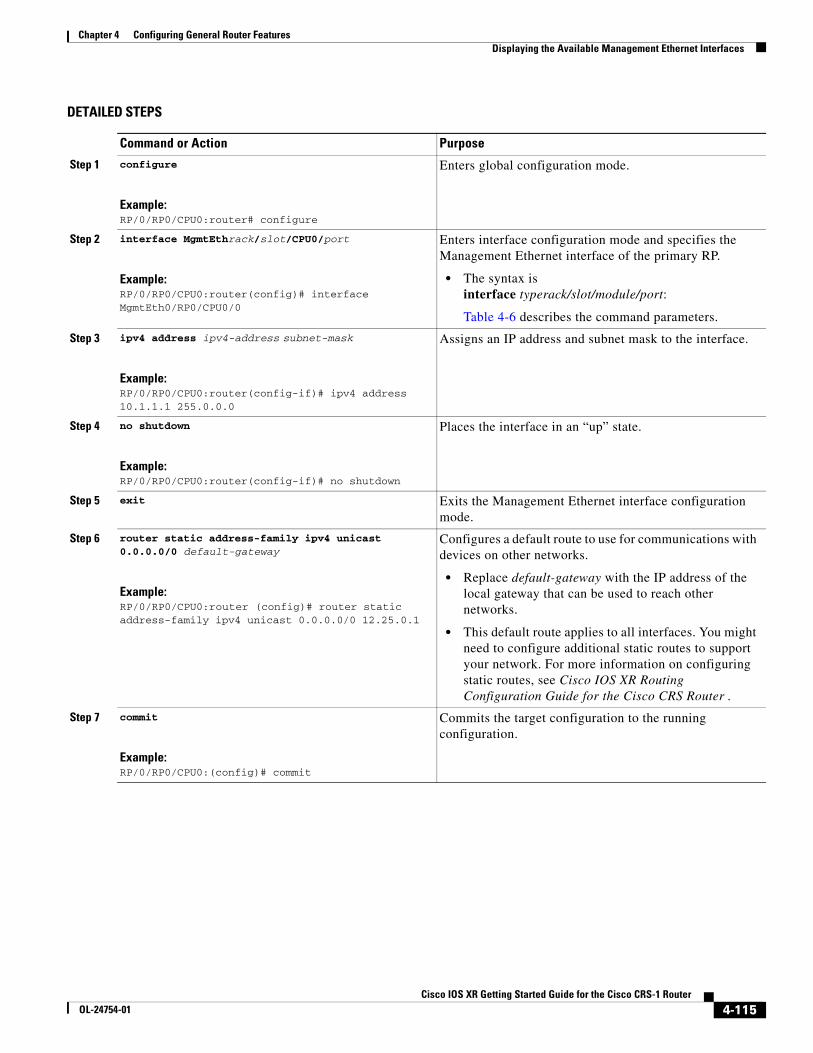
Chapter 4 Configuring General Router Features Displaying the Available Management Ethernet Interfaces
DETAILED STEPS
Command or Action Purpose
Step 1 configure
Example:RP/0/RP0/CPU0:router# configure
Enters global configuration mode.
Step 2 interface MgmtEthrack/slot/CPU0/port
Example:RP/0/RP0/CPU0:router(config)# interface MgmtEth0/RP0/CPU0/0
Enters interface configuration mode and specifies the Management Ethernet interface of the primary RP.
• The syntax is interface typerack/slot/module/port:
Table 4-6 describes the command parameters.
Step 3 ipv4 address ipv4-address subnet-mask
Example:RP/0/RP0/CPU0:router(config-if)# ipv4 address 10.1.1.1 255.0.0.0
Assigns an IP address and subnet mask to the interface.
Step 4 no shutdown
Example:RP/0/RP0/CPU0:router(config-if)# no shutdown
Places the interface in an “up” state.
Step 5 exit Exits the Management Ethernet interface configuration mode.
Step 6 router static address-family ipv4 unicast 0.0.0.0/0 default-gateway
Example:RP/0/RP0/CPU0:router (config)# router static address-family ipv4 unicast 0.0.0.0/0 12.25.0.1
Configures a default route to use for communications with devices on other networks.
• Replace default-gateway with the IP address of the local gateway that can be used to reach other networks.
• This default route applies to all interfaces. You might need to configure additional static routes to support your network. For more information on configuring static routes, see Cisco IOS XR Routing Configuration Guide for the Cisco CRS Router .
Step 7 commit
Example:RP/0/RP0/CPU0:(config)# commit
Commits the target configuration to the running configuration.
4-115Cisco IOS XR Getting Started Guide for the Cisco CRS-1 Router
OL-24754-01
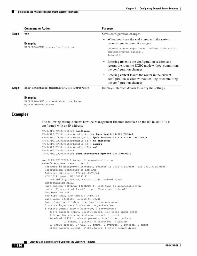
Chapter 4 Configuring General Router Features Displaying the Available Management Ethernet Interfaces
Examples
The following example shows how the Management Ethernet interface on the RP in slot RP1 is configured with an IP address.
RP/0/RP0/CPU0:router# configureRP/0/RP0/CPU0:router(config)# interface MgmtEth0/RP1/CPU0/0RP/0/RP0/CPU0:router(config-if)# ipv4 address 10.1.1.1 255.255.255.0RP/0/RP0/CPU0:router(config-if)# no shutdownRP/0/RP0/CPU0:router(config-if)# commitRP/0/RP0/CPU0:router(config-if)# endRP/0/RP0/CPU0:router#RP/0/RP0/CPU0:router# show interfaces MgmtEth 0/RP0/CPU0/0
MgmtEth0/RP0/CPU0/0 is up, line protocol is up Interface state transitions: 1 Hardware is Management Ethernet, address is 0011.93ef.e8e6 (bia 0011.93ef.e8e6) Description: Connected to Lab LAN Internet address is 172.29.52.70/24 MTU 1514 bytes, BW 100000 Kbit reliability 255/255, txload 0/255, rxload 0/255 Encapsulation ARPA, Half-duplex, 100Mb/s, 1000BASE-T, link type is autonegotiation output flow control is off, input flow control is off loopback not set, ARP type ARPA, ARP timeout 04:00:00 Last input 00:00:00, output 00:00:00 Last clearing of "show interface" counters never 5 minute input rate 0 bits/sec, 0 packets/sec 5 minute output rate 0 bits/sec, 0 packets/sec 31371 packets input, 1922996 bytes, 153 total input drops 0 drops for unrecognized upper-level protocol Received 19457 broadcast packets, 0 multicast packets 12 runts, 0 giants, 0 throttles, 0 parity 61 input errors, 27 CRC, 12 frame, 0 overrun, 0 ignored, 0 abort 12869 packets output, 878236 bytes, 0 total output drops
Step 8 end
Example:RP/0/RP0/CPU0:router(config)# end
Saves configuration changes.
• When you issue the end command, the system prompts you to commit changes:
Uncommitted changes found, commit them before exiting(yes/no/cancel)?[cancel]:
• Entering no exits the configuration session and returns the router to EXEC mode without committing the configuration changes.
• Entering cancel leaves the router in the current configuration session without exiting or committing the configuration changes.
Step 9 show interfaces MgmtEthrack/slot/CPU0/port
Example:RP/0/RP0/CPU0:router# show interfaces MgmtEth0/RP0/CPU0/0
Displays interface details to verify the settings.
Command or Action Purpose
4-116Cisco IOS XR Getting Started Guide for the Cisco CRS-1 Router
OL-24754-01
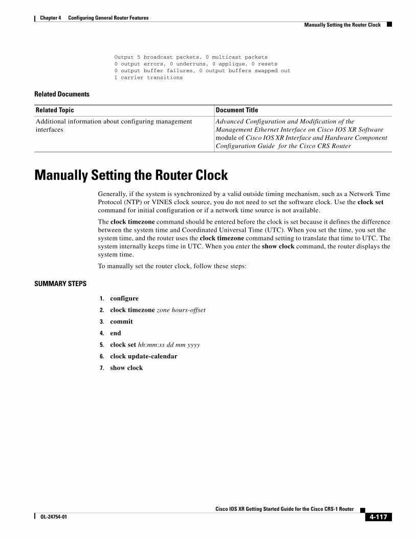
Chapter 4 Configuring General Router Features Manually Setting the Router Clock
Output 5 broadcast packets, 0 multicast packets 0 output errors, 0 underruns, 0 applique, 0 resets 0 output buffer failures, 0 output buffers swapped out 1 carrier transitions
Related Documents
Manually Setting the Router ClockGenerally, if the system is synchronized by a valid outside timing mechanism, such as a Network Time Protocol (NTP) or VINES clock source, you do not need to set the software clock. Use the clock set command for initial configuration or if a network time source is not available.
The clock timezone command should be entered before the clock is set because it defines the difference between the system time and Coordinated Universal Time (UTC). When you set the time, you set the system time, and the router uses the clock timezone command setting to translate that time to UTC. The system internally keeps time in UTC. When you enter the show clock command, the router displays the system time.
To manually set the router clock, follow these steps:
SUMMARY STEPS
1. configure
2. clock timezone zone hours-offset
3. commit
4. end
5. clock set hh:mm:ss dd mm yyyy
6. clock update-calendar
7. show clock
Related Topic Document Title
Additional information about configuring management interfaces
Advanced Configuration and Modification of the Management Ethernet Interface on Cisco IOS XR Software module of Cisco IOS XR Interface and Hardware Component Configuration Guide for the Cisco CRS Router
4-117Cisco IOS XR Getting Started Guide for the Cisco CRS-1 Router
OL-24754-01
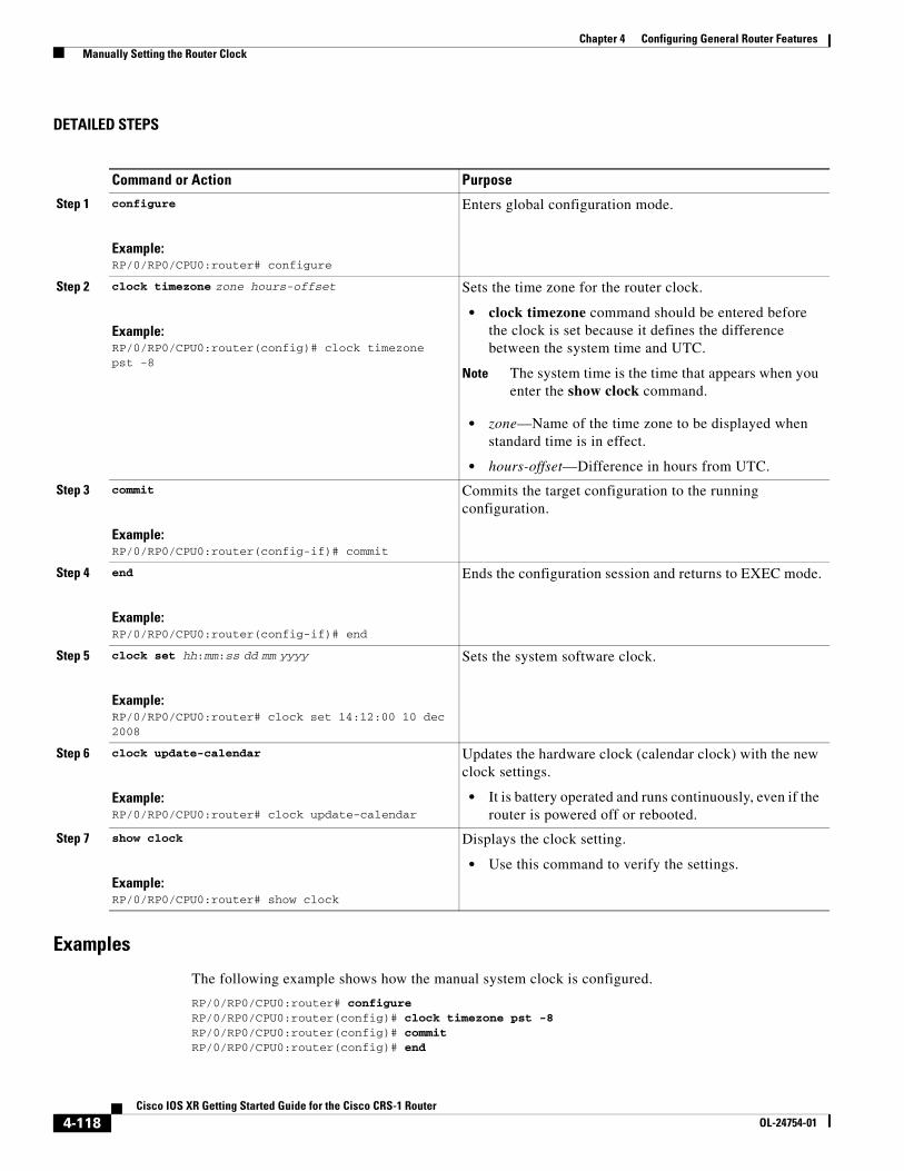
Chapter 4 Configuring General Router Features Manually Setting the Router Clock
DETAILED STEPS
Examples
The following example shows how the manual system clock is configured.
RP/0/RP0/CPU0:router# configureRP/0/RP0/CPU0:router(config)# clock timezone pst -8RP/0/RP0/CPU0:router(config)# commitRP/0/RP0/CPU0:router(config)# end
Command or Action Purpose
Step 1 configure
Example:RP/0/RP0/CPU0:router# configure
Enters global configuration mode.
Step 2 clock timezone zone hours-offset
Example:RP/0/RP0/CPU0:router(config)# clock timezone pst -8
Sets the time zone for the router clock.
• clock timezone command should be entered before the clock is set because it defines the difference between the system time and UTC.
Note The system time is the time that appears when you enter the show clock command.
• zone—Name of the time zone to be displayed when standard time is in effect.
• hours-offset—Difference in hours from UTC.
Step 3 commit
Example:RP/0/RP0/CPU0:router(config-if)# commit
Commits the target configuration to the running configuration.
Step 4 end
Example:RP/0/RP0/CPU0:router(config-if)# end
Ends the configuration session and returns to EXEC mode.
Step 5 clock set hh:mm:ss dd mm yyyy
Example:RP/0/RP0/CPU0:router# clock set 14:12:00 10 dec 2008
Sets the system software clock.
Step 6 clock update-calendar
Example:RP/0/RP0/CPU0:router# clock update-calendar
Updates the hardware clock (calendar clock) with the new clock settings.
• It is battery operated and runs continuously, even if the router is powered off or rebooted.
Step 7 show clock
Example:RP/0/RP0/CPU0:router# show clock
Displays the clock setting.
• Use this command to verify the settings.
4-118Cisco IOS XR Getting Started Guide for the Cisco CRS-1 Router
OL-24754-01
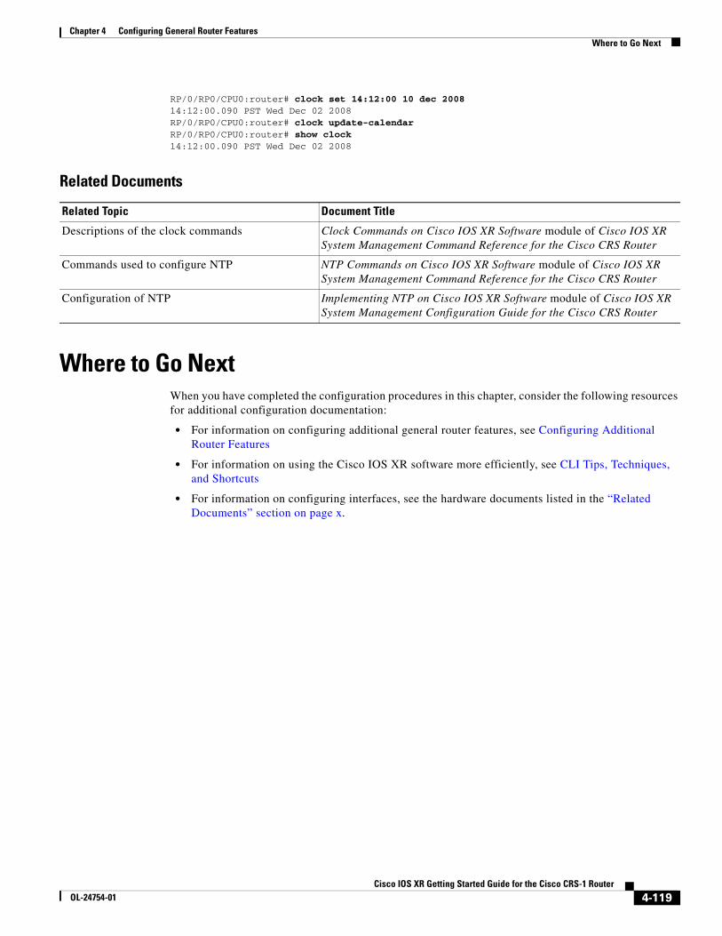
Chapter 4 Configuring General Router Features Where to Go Next
RP/0/RP0/CPU0:router# clock set 14:12:00 10 dec 200814:12:00.090 PST Wed Dec 02 2008RP/0/RP0/CPU0:router# clock update-calendarRP/0/RP0/CPU0:router# show clock14:12:00.090 PST Wed Dec 02 2008
Related Documents
Where to Go NextWhen you have completed the configuration procedures in this chapter, consider the following resources for additional configuration documentation:
• For information on configuring additional general router features, see Configuring Additional Router Features
• For information on using the Cisco IOS XR software more efficiently, see CLI Tips, Techniques, and Shortcuts
• For information on configuring interfaces, see the hardware documents listed in the “Related Documents” section on page x.
Related Topic Document Title
Descriptions of the clock commands Clock Commands on Cisco IOS XR Software module of Cisco IOS XR System Management Command Reference for the Cisco CRS Router
Commands used to configure NTP NTP Commands on Cisco IOS XR Software module of Cisco IOS XR System Management Command Reference for the Cisco CRS Router
Configuration of NTP Implementing NTP on Cisco IOS XR Software module of Cisco IOS XR System Management Configuration Guide for the Cisco CRS Router
4-119Cisco IOS XR Getting Started Guide for the Cisco CRS-1 Router
OL-24754-01

Chapter 4 Configuring General Router Features Where to Go Next
4-120Cisco IOS XR Getting Started Guide for the Cisco CRS-1 Router
OL-24754-01