Embed Size (px)
Citation preview

Configure
This chapter contains the following topics:
• Templates, on page 1• Backup, on page 27• Image Management, on page 39• SAN, on page 57
TemplatesThe Templates menu includes the following option:
Template LibraryTemplate Library includes the following tabs:
Template LibraryYou can add, edit, or delete templates that are configured across different Cisco Nexus and Cisco MDSplatforms using Cisco DCNMWeb client. From Cisco DCNMWeb client home page, choose Configure >Templates > Template Library > Templates. The following parameters are displayed for each templatethat is configured on Cisco DCNMWeb client. Templates support JavaScript. You can use the JavaScriptfunction in a template to perform arithmetic operations and string manipulations in the template syntax.
The following table describes the fields that appear on this page.
Table 1: Templates Operations
DescriptionField
Allows you to add a new template.Add Template
Allows you to create jobs.Launch job creation wizard
Allows you to view the template definition and modify as required.Modify/View Template
Allows you to save the selected template in a different name. Youcan edit the template as required.
Save Template As
Configure1
DescriptionField
Allows you to delete a templateDelete Template
Allows you to import a template from your local directory, one ata time.
Import Template
Allows you to export the template configuration to a local directorylocation.
Export template
Allows you to import .zip file, that contains more than onetemplate that is bundled in a .zip format
All the templates in the ZIP file are extracted and listed in the tableas individual templates.
Import Template Zip File
Notifications appear next to Import Template Zip File if there are issues while loading templates afterrestarting the server. Click the notifications to see the errors in the Issues in loading Template window.Templates with errors are not listed in the Templates window. To import these templates, correct the errors,and import them.
Note
Table 2: Template Properties
DescriptionField
Displays the name of the configured template.Template Name
Displays the description that is provided while configuringtemplates.
Template Description
Displays the tag that is assigned for the template and aids to filtertemplates based on the tags.
Tags
Displays the supported Cisco Nexus platforms compatible with thetemplate. Check the check box of platforms that are supported withthe template.
You can select multiple platforms.Note
Supported Platforms
Displays the type of the template.Template Type
Specifies the sub type that is associated with the template.Template Sub Type
Specifies if it is Jython or Template CLI.Template Content Type
Table 3: Advanced Template Properties
DescriptionField
Displays the abstract template to be implemented.Implements
Configure2
ConfigureTemplate Library

DescriptionField
Specifies the specific feature of a switch.Dependencies
Specifies if the template is published or not.Published
Specifies the base template for importing.Imports
In addition, from the menu bar, choose Configure > Templates > Template Library > Templates and youcan also:
• Click Show Filter to filter the templates that is based on the headers.
• Click Print to print the list of templates.
• Click Export to Excel to export the list of template to a Microsoft Excel spreadsheet.
This section contains the following:
Template Structure
The configuration template content mainly consists of four parts. Click the Help icon next to the TemplateContent for information about editing the content of the template.
This section contains the following:
Template Format
This section describes the basic information of the template. The possible fields are as detailed in the tablebelow.
Optional?Valid ValuesDescriptionProperty Name
NoTextThe name of the templatename
YesTextBrief description about thetemplate
description
Yes“true” or “false”Indicates whether the usercreated the template. Value is‘true’ if user created.
userDefined
NoN1K, N3K, N3500, N4K, N5K,N5500, N5600, N6K, N7K, N9K,MDS, VDC, N9K-9000v, All listseparated by comma.
List of device platformssupports this configurationtemplate. Specify ‘All’ tosupport all platforms.
supportedPlatforms
Configure3
ConfigureTemplate Structure

Optional?Valid ValuesDescriptionProperty Name
Yes• CLI
• POAP
• POLICY
• SHOW
• PROFILE
• FABRIC
• ABSTRACT
Specifies the type of Templateused.
templateType
Configure4
ConfigureTemplate Format

Optional?Valid ValuesDescriptionProperty Name
Specifies the sub typeassociated with the template.
templateSubType
Configure5
ConfigureTemplate Format

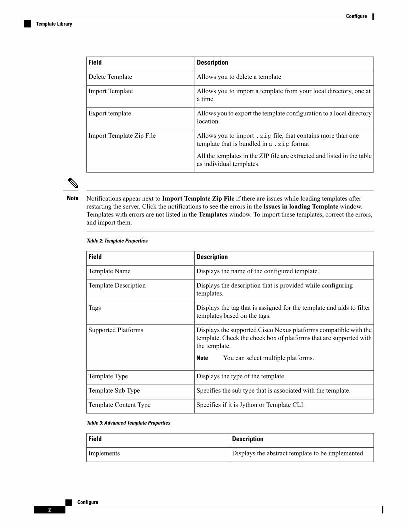
Optional?Valid ValuesDescriptionProperty Name
• CLI
• N/A
• POAP
• N/A
• VXLAN
• FABRICPATH
• VLAN
• PMN
• POLICY
• VLAN
• INTERFACE_VLAN
• INTERFACE_VPC
• INTERFACE_ETHERNET
• INTERFACE_BD
• INTERFACE_PORT_CHANNEL
• INTERFACE_FC
• INTERFACE_MGMT
• INTERFACE_LOOPBACK
• INTERFACE_NVE
• INTERFACE_VFC
• INTERFACE_SAN_PORT_CHANNEL
• DEVICE
• FEX
• INTRA_FABRIC_LINK
• INTER_FABRIC_LINK
• INTERFACE
• SHOW
• VLAN
• INTERFACE_VLAN
• INTERFACE_VPC
Configure6
ConfigureTemplate Format
Optional?Valid ValuesDescriptionProperty Name
• INTERFACE_ETHERNET
• INTERFACE_BD
• INTERFACE_PORT_CHANNEL
• INTERFACE_FC
• INTERFACE_MGMT
• INTERFACE_LOOPBACK
• INTERFACE_NVE
• INTERFACE_VFC
• INTERFACE_SAN_PORT_CHANNEL
• DEVICE
• FEX
• INTRA_FABRIC_LINK
• INTER_FABRIC_LINK
• INTERFACE
• PROFILE
• VXLAN
• FABRIC
• NA
Configure7
ConfigureTemplate Format

Optional?Valid ValuesDescriptionProperty Name
• ABSTRACT
• VLAN
• INTERFACE_VLAN
• INTERFACE_VPC
• INTERFACE_ETHERNET
• INTERFACE_BD
• INTERFACE_PORT_CHANNEL
• INTERFACE_FC
• INTERFACE_MGMT
• INTERFACE_LOOPBACK
• INTERFACE_NVE
• INTERFACE_VFC
• INTERFACE_SAN_PORT_CHANNEL
• DEVICE
• FEX
• INTRA_FABRIC_LINK
• INTER_FABRIC_LINK
• INTERFACE
Configure8
ConfigureTemplate Format

Optional?Valid ValuesDescriptionProperty Name
Yes• CLI
• TEMPLATE_CLI
• POAP
• TEMPLATE_CLI
• POLICY
• TEMPLATE_CLI
• PYTHON
• SHOW
• TEMPLATE_CLI
• PROFILE
• TEMPLATE_CLI
• PYTHON
• FABRIC
• PYTHON
• ABSTRACT
• TEMPLATE_CLI
• PYTHON
contentType
YesTextUsed to implement the abstracttemplate.
implements
YesTextUsed to select the specificfeature of a switch.
dependencies
Yes“true” or “false”Used to Mark the template asread only and avoids changesto it.
published
Template Variables
This section contains declared variables, the data type, default values, and valid values conditions for theparameters that are used in the template. These declared variables are used for value substitution in the templatecontent section during the dynamic command generation process. Also these variables are used in decisionmaking and in iteration blocks in the template content section. Variables have predefined data types. You canalso add a description about the variable. The following table describes the syntax and usage for the availabledatatypes.
Configure9
ConfigureTemplate Variables

Iterative?Valid ValueVariable Type
Notrue|falseboolean
NoExample: running-config, startup-config
enum
NoFloating number formatfloat
YesExample: 10.1,50.01
floatRange
NoAny numberInteger
YesContiguous numbers separated by “-“
Discrete numbers separated by “,”
Example: 1-10,15,18,20
integerRange
NoFormat: <if type><slot>[/<sub slot>]/<port>
Example: eth1/1, fa10/1/2 etc.
interface
YesExample: eth10/1/20-25, eth11/1-5
interfaceRange
NoIPv4 OR IPv6 addressipAddress
YesExample: 172.22.31.97, 172.22.31.99,172.22.31.105, 172.22.31.109
ipAddressList
NoExample: 192.168.1.1
orExample: 1:2:3:4:5:6:7:8
ipAddressWithoutPrefix
YesExample:{192.168.1.1, 192.168.1.2, 10.1.1.1}
ipAddress[]
NoIPv4 addressipV4Address
NoExample: 192.168.1.1/24ipV4AddressWithSubnet
NoIPv6 addressipV6Address
NoExample: 1:2:3:4:5:6:7:8
22
ipV6AddressWithPrefix
NoIPv6 Address with SubnetipV6AddressWithSubnet
NoExample: 49.0001.00a0.c96b.c490.00ISISNetAddress
No14 or 17 character length MAC address formatmacAddress
Configure10
ConfigureTemplate Variables
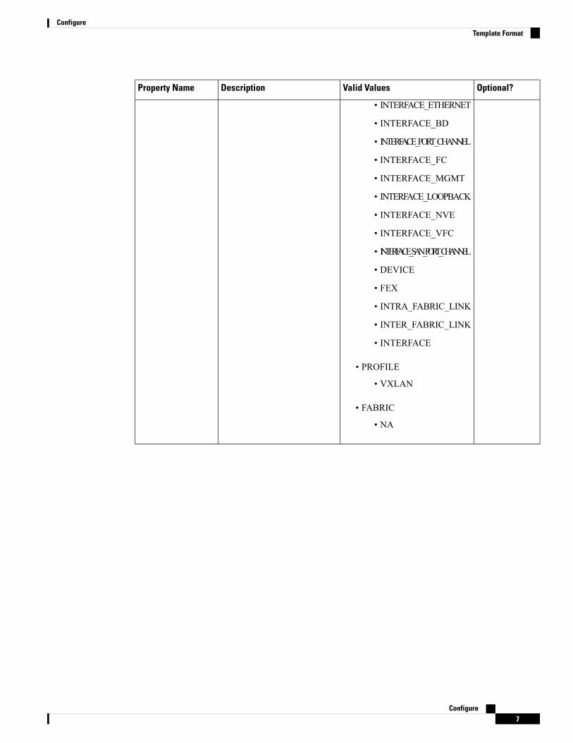
Iterative?Valid ValueVariable Type
NoFree text
Example: Description for the variable
string
YesExample: {a,b,c,str1,str2}
string[]
NoExample: 20:01:00:08:02:11:05:03
wwn
(Available only in Cisco DCNMWebClient)
Example: Template Variables
##template variablesinteger VSAN_ID;string SLOT_NUMBER;integerRange PORT_RANGE;integer VFC_PREFIX;##
Variable Meta Property
Each variable that is defined in the template variable section has a set of meta properties. The meta propertiesare mainly the validation rules that are defined for the variable.
The following table describes the various meta properties applicable for the available variable types.
Variable Meta PropertyDescriptionVariableType
regularExpr
maxLength
minLength
maxPort
minPort
maxSlot
minSlot
maxmindecimalLength
validValues
defaultValue
YesAbooleanvalue.Example:true
boolean
Yesenum
YesYesYesYesYessignedrealnumber.Example:
75.56,-8.5
float
Configure11
ConfigureVariable Meta Property

Variable Meta PropertyDescriptionVariableType
regularExpr
maxLength
minLength
maxPort
minPort
maxSlot
minSlot
maxmindecimalLength
validValues
defaultValue
YesYesYesYesYesrangeofsignedrealnumbersExample:50.5-54.75
floatRange
YesYesYesYessignednumberExample:50,-75
integer
YesYesYesYesRangeofsignednumbersExample:50-65
integerRange
YesYesYesYesYesYesspecifiesinterface/portExample:
Ethernet5/10
interface
YesYesYesYesYesYesinterfaceRange
YesIPaddressinIPv4orIPv6format
ipAddress
Configure12
ConfigureVariable Meta Property

Variable Meta PropertyDescriptionVariableType
regularExpr
maxLength
minLength
maxPort
minPort
maxSlot
minSlot
maxmindecimalLength
validValues
defaultValue
YesExample:
192.10.2.10,
172.68.10.1
Separatetheaddressesin thelist usingcommasand nothyphens.
Note
ipAddressList
IPv4orIPv6Address(doesnotrequireprefix/subnet).
ipAddressWithoutPrefix
YesListof IPaddressesseparatedby acomma(,)
ipAddress[]
YesIPv4address
ipV4Address
YesIPv4AddresswithSubnet
ipV4AddressWithSubnet
YesIPv6address
ipV6Address
YesIPv6Addresswithprefix
ipV6AddressWithPrefix
Configure13
ConfigureVariable Meta Property

Variable Meta PropertyDescriptionVariableType
regularExpr
maxLength
minLength
maxPort
minPort
maxSlot
minSlot
maxmindecimalLength
validValues
defaultValue
YesIPv6AddresswithSubnet
ipV6AddressWithSubnet
Example:
49.0001.00a0.c96b.c490.00
ISISNetAddress
YesYesYesExample:100
long
MACaddress
macAddress
YesYesYesYesliteralstring
string
Yesstringliteralsthatareseparatedby acomma(,)Example:
{string1,
string2}
string[]
Configure14
ConfigureVariable Meta Property

Variable Meta PropertyDescriptionVariableType
regularExpr
maxLength
minLength
maxPort
minPort
maxSlot
minSlot
maxmindecimalLength
validValues
defaultValue
Set ofparametersthatarebundledunderasinglevariable.struct
<structurenamedeclaration> {<parametertype>
<parameter1>;<parametertype>
<parameter2>;…..}[<structure_inst1>][,<structure_inst2>][,<structure_array_inst3[]>];
struct
WWNaddress
wwn
Example: Meta Property Usage
##template variables
integer VLAN_ID {min = 100;max= 200;};
string USER_NAME {defaultValue = admin123;minLength = 5;};
struct interface_a{
Configure15
ConfigureVariable Meta Property
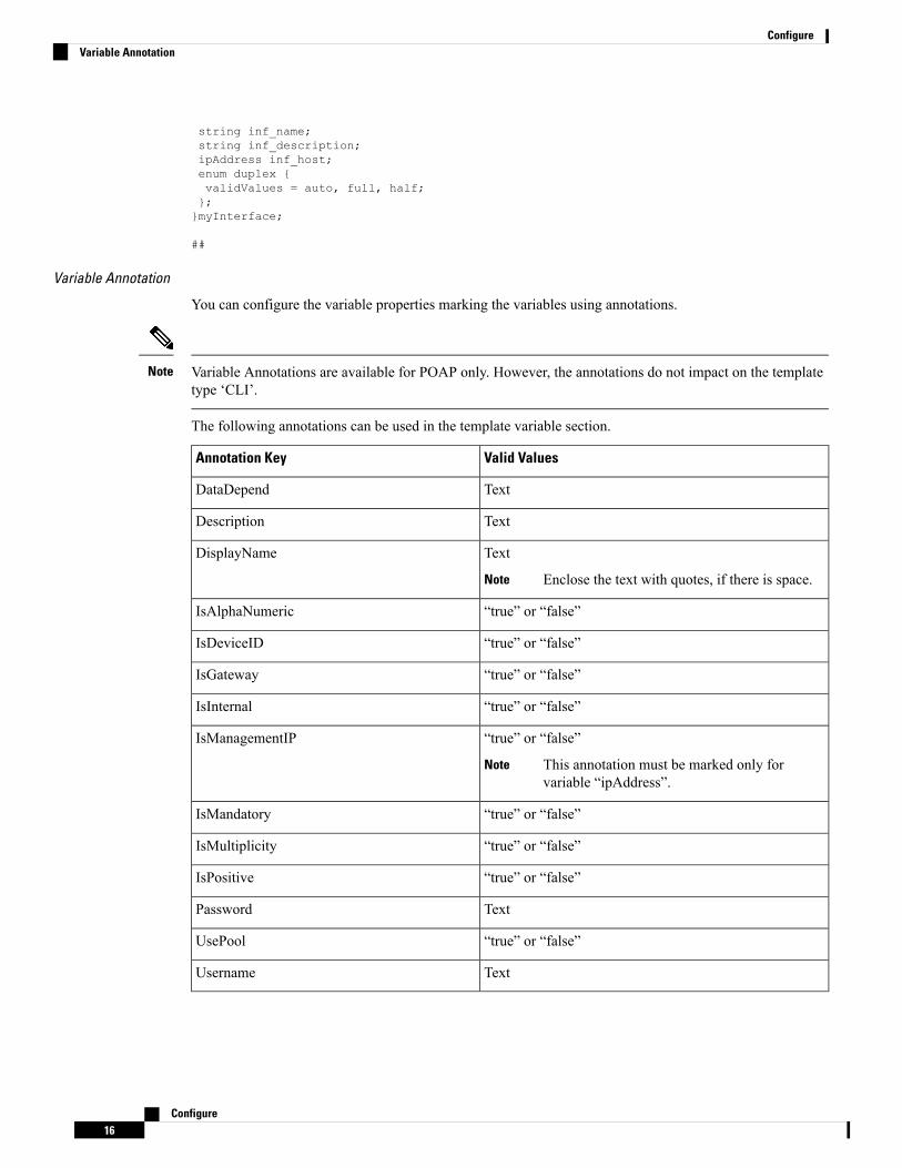
string inf_name;string inf_description;ipAddress inf_host;enum duplex {validValues = auto, full, half;};}myInterface;
##
Variable Annotation
You can configure the variable properties marking the variables using annotations.
Variable Annotations are available for POAP only. However, the annotations do not impact on the templatetype ‘CLI’.
Note
The following annotations can be used in the template variable section.
Valid ValuesAnnotation Key
TextDataDepend
TextDescription
Text
Enclose the text with quotes, if there is space.Note
DisplayName
“true” or “false”IsAlphaNumeric
“true” or “false”IsDeviceID
“true” or “false”IsGateway
“true” or “false”IsInternal
“true” or “false”
This annotation must be marked only forvariable “ipAddress”.
Note
IsManagementIP
“true” or “false”IsMandatory
“true” or “false”IsMultiplicity
“true” or “false”IsPositive
TextPassword
“true” or “false”UsePool
TextUsername
Configure16
ConfigureVariable Annotation

Example: Variable Annotation
##template variables@(DisplayName="Host Name", Description = "Description of the host")String hostname;@(DisplayName="Host Address", Description = " test description" IsManagementIP=true)ipAddress hostAddress;##
Example: IsMandatory Annotation
##template variables@(IsMandatory="ipv6!=null")ipV4Address ipv4;@(IsMandatory="ipv4!=null")ipV6Address ipv6;##
IsShowAnnotation
##template variablesboolean isVlan;@(IsShow="isVlan==true")integer vlanNo;##
Templates Content
This section includes the configuration commands and any parameters that you want to include in the template.These commands can include the variables declared in the template variables section. During the commandgeneration process the variable values are substituted appropriately in the template content.
You must specify the commands that you include as if you were entering them in the global configurationcommand mode on any device. You must consider the command mode when you include commands.
Note
Template content is governed by the usage of variables.
• Scalar variables—does not take a range or array of values which cannot be used for iteration (In thevariable types table those marked iterate-able as 'No'). Scalar variables must be defined inside the templatecontent.
Syntax: $$<variable name>$$Example: $$USER_NAME$$
• Iterative variables—used for block iteration. These loop variable must be accessed as shown below insidethe iteration block.
Syntax:@<loop variable>Example:foreach val in $$INTEGER_RANGE_VALUE$$ {@val}
• Scalar Structure Variable—Structure member variables can be accessed inside the template content.
Syntax: $$<structure instance name>.<member variable name>$$Example: $$myInterface.inf_name$$
Configure17
ConfigureTemplates Content

• Array Structure Variable—Structure member variables can be accessed inside the template content.
Syntax: $$<structure instance name>.<member variable name>$$Example: $$myInterface.inf_name$$
In addition to the template variables, you can use the conditional and iterative command generation using thefollowing statements:
• if-else if-else Statement—makes a logical decision in inclusion/exclusion of set of configuration commandbased on the value assigned for the variable in it.
Syntax: if(<operand 1> <logical operator> <operand 2>){command1 ..command2....}else if (<operand 3> <logical operator> <operand 4> ){Command3 ..Command4....}else{Command5 ..Command6....}Example: if-else if-else statementif($$USER_NAME$$ == 'admin'){Interface2/10no shut}else {Interface2/10shut}
• foreach Statement—used for iterating a block of commands. The iteration is performed based on theassigned loop variable value.
Syntax:foreach <loop index variable> in $$<loop variable>$$ {@<loop index variable> ..}Example: foreach Statementforeach ports in $$MY_INF_RANGE$${interface @portsno shut}
• Optional parameters—By default all parameters are mandatory. To make a parameter optional, you mustannotate the parameter.
In the variable section, you can include the following command:
• @(IsMandatory=false)
• Integer frequency;
Configure18
ConfigureTemplates Content

In the template content section, a command can be excluded or included without using “if” conditioncheck, by assigning a value to the parameter. The optional command can be framed as below:
• probe icmp [frequency frequency-value] [timeout seconds] [retry-count retry-count-value]
Template Content Editor
The template content editor has the following features:
• Syntax highlighting: The editor highlights the syntax, like different types of statements, keywords, andso on, for Python scripting.
• Autocompletion: The editor suggests the template datatypes, annotations, or metaproperties when youstart typing.
• Go to line: You can navigate to the exact line in the template content editor instead of scrolling. PressCommand-L in Mac or Ctrl-L in Windows, and enter the line number to which you want to navigateto in the pop-up window.
If you enter a value greater than the number of lines in the editor, you will be navigated to the last linein the editor window.
• Template search and replace: Press Command-F in Mac or Ctrl-F in Windows, enter the search termin the Search for field, and select the type of search in the search window. You can perform the followingsearches in the editor:
• RegExp Search: You can perform the regular expression search in the editor.
• CaseSensitive Search: You can perform a case-sensitive search in the editor.
• Whole Word Search: You can perform a whole word search to find the exact words in the editor.For example, a regular search for the word "play" returns results where it is part of words like"display," but the whole word search returns results only when there is an exact match for the word"play".
• Search In Selection: You can perform a search in the selected content. Select the content to whichyou want to limit the search and enter the search term.
Choose the + icon in the search window to use the replace option. Enter the replacing word in theReplacewith field. You can replace the selected word once by selecting Replace. To replace all the occurencesof the selected word, select All.
• Code folding: You can expand or group code blocks in the editor by clicking the arrow next to their linenumbers.
• Other features: The editor automatically indents the code, the closing braces, and highlights the matchingparenthesis.
Template Editor Settings
You can edit the following features of a template editor by clicking Template Editor Settings.
• Theme: Select the required theme for the editor from the drop-down list.
• KeyBinding: Select the editor mode from the KeyBinding drop-down list to customize the editor. Vimand Ace modes are supported. The default is Ace.
• Font Size: Select the required font size for the editor.
Configure19
ConfigureTemplate Content Editor
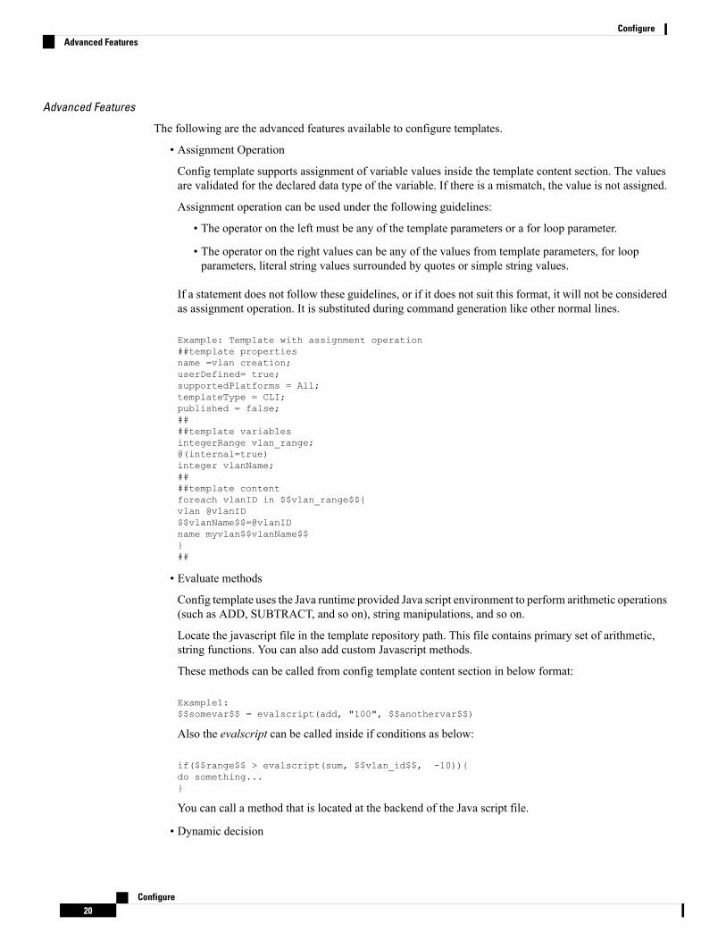
Advanced Features
The following are the advanced features available to configure templates.
• Assignment Operation
Config template supports assignment of variable values inside the template content section. The valuesare validated for the declared data type of the variable. If there is a mismatch, the value is not assigned.
Assignment operation can be used under the following guidelines:
• The operator on the left must be any of the template parameters or a for loop parameter.
• The operator on the right values can be any of the values from template parameters, for loopparameters, literal string values surrounded by quotes or simple string values.
If a statement does not follow these guidelines, or if it does not suit this format, it will not be consideredas assignment operation. It is substituted during command generation like other normal lines.
Example: Template with assignment operation##template propertiesname =vlan creation;userDefined= true;supportedPlatforms = All;templateType = CLI;published = false;####template variablesintegerRange vlan_range;@(internal=true)integer vlanName;####template contentforeach vlanID in $$vlan_range$${vlan @vlanID$$vlanName$$=@vlanIDname myvlan$$vlanName$$}##
• Evaluate methods
Config template uses the Java runtime provided Java script environment to perform arithmetic operations(such as ADD, SUBTRACT, and so on), string manipulations, and so on.
Locate the javascript file in the template repository path. This file contains primary set of arithmetic,string functions. You can also add custom Javascript methods.
These methods can be called from config template content section in below format:
Example1:$$somevar$$ = evalscript(add, "100", $$anothervar$$)
Also the evalscript can be called inside if conditions as below:
if($$range$$ > evalscript(sum, $$vlan_id$$, -10)){do something...}
You can call a method that is located at the backend of the Java script file.
• Dynamic decision
Configure20
ConfigureAdvanced Features
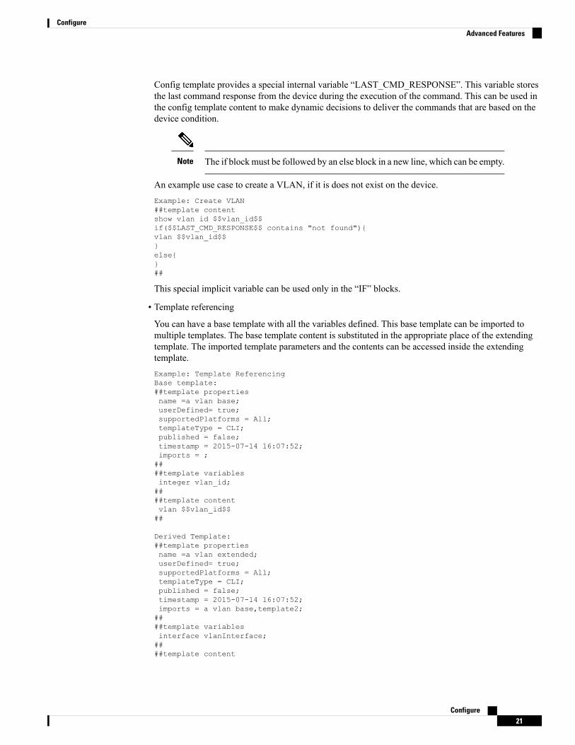
Config template provides a special internal variable “LAST_CMD_RESPONSE”. This variable storesthe last command response from the device during the execution of the command. This can be used inthe config template content to make dynamic decisions to deliver the commands that are based on thedevice condition.
The if block must be followed by an else block in a new line, which can be empty.Note
An example use case to create a VLAN, if it is does not exist on the device.Example: Create VLAN##template contentshow vlan id $$vlan_id$$if($$LAST_CMD_RESPONSE$$ contains "not found"){vlan $$vlan_id$$}else{}##
This special implicit variable can be used only in the “IF” blocks.
• Template referencing
You can have a base template with all the variables defined. This base template can be imported tomultiple templates. The base template content is substituted in the appropriate place of the extendingtemplate. The imported template parameters and the contents can be accessed inside the extendingtemplate.Example: Template ReferencingBase template:##template propertiesname =a vlan base;userDefined= true;supportedPlatforms = All;templateType = CLI;published = false;timestamp = 2015-07-14 16:07:52;imports = ;####template variablesinteger vlan_id;####template contentvlan $$vlan_id$$##
Derived Template:##template propertiesname =a vlan extended;userDefined= true;supportedPlatforms = All;templateType = CLI;published = false;timestamp = 2015-07-14 16:07:52;imports = a vlan base,template2;####template variablesinterface vlanInterface;####template content
Configure21
ConfigureAdvanced Features

<substitute a vlan base>interface $$vlanInterface$$<substitute a vlan base>##
When you launch the extended template, the parameter inputs for the base template are also obtained.In addition, the substituted content is used for complete CLI command generation.
• Solution POAP Templates for VXLAN and FabricPath
From Cisco DCNM Release 10.0(1), Cisco provides you a set of defined templates to aid in POAPoperations. You can download Cisco-defined templates fromhttps://software.cisco.com/download/release.html.
For instructions on how to download and install POAP templates, see Cisco DCNM Installation Guide,Release 10.0(x).
Adding a Template
To add user-defined templates and schedule jobs from the Cisco DCNMWeb UI, perform the following steps:
Procedure
Step 1 Choose Configure > Templates > Template Library > Templates.
The Templates window is displayed with the name of the template along with its description, supportedplatforms, and tags.
Step 2 Click Add to add a new template.
The Template Properties window appears.
Step 3 Specify a template name, description, tags, and supported platforms for the new template.Step 4 Specify a Template Type for the template. Select POAP to make this template available when you power
on the application.
The template is considered as a CLI template if POAP is not selected.Note
Step 5 Select a Template Sub Type and Template Content Type for the template.Step 6 Click the Advanced tab to edit other properties like Implements, Dependencies, Published, and Imports.
Select Published to make the template read-only. You cannot edit a published template.Step 7 From the Imports > Template Name list, check the template check box.
The base template content is displayed in the Template Content window. The base template displays thetemplate properties, template variables, and template content. This template can be imported in to anothertemplate and the base template content is substituted in the appropriate place of the extending template. Whenyou launch the extended template, the parameter inputs for the base template are also obtained. Also, thesubstituted content is used for complete CLI command generation.
The base templates are CLI templates.Note
Step 8 Click OK to save the template properties, or click the cancel icon at the top-right corner of the window torevert the changes.
You can edit the template properties by clicking Template Property.Note
Configure22
ConfigureAdding a Template
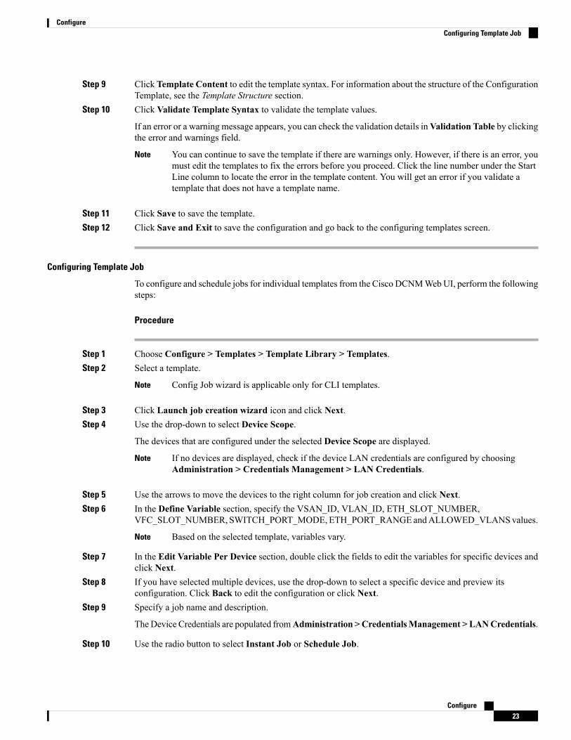
Step 9 Click Template Content to edit the template syntax. For information about the structure of the ConfigurationTemplate, see the Template Structure section.
Step 10 Click Validate Template Syntax to validate the template values.
If an error or a warning message appears, you can check the validation details inValidation Table by clickingthe error and warnings field.
You can continue to save the template if there are warnings only. However, if there is an error, youmust edit the templates to fix the errors before you proceed. Click the line number under the StartLine column to locate the error in the template content. You will get an error if you validate atemplate that does not have a template name.
Note
Step 11 Click Save to save the template.Step 12 Click Save and Exit to save the configuration and go back to the configuring templates screen.
Configuring Template Job
To configure and schedule jobs for individual templates from the Cisco DCNMWebUI, perform the followingsteps:
Procedure
Step 1 Choose Configure > Templates > Template Library > Templates.Step 2 Select a template.
Config Job wizard is applicable only for CLI templates.Note
Step 3 Click Launch job creation wizard icon and click Next.Step 4 Use the drop-down to select Device Scope.
The devices that are configured under the selected Device Scope are displayed.
If no devices are displayed, check if the device LAN credentials are configured by choosingAdministration > Credentials Management > LAN Credentials.
Note
Step 5 Use the arrows to move the devices to the right column for job creation and click Next.Step 6 In the Define Variable section, specify the VSAN_ID, VLAN_ID, ETH_SLOT_NUMBER,
VFC_SLOT_NUMBER, SWITCH_PORT_MODE, ETH_PORT_RANGEandALLOWED_VLANSvalues.
Based on the selected template, variables vary.Note
Step 7 In the Edit Variable Per Device section, double click the fields to edit the variables for specific devices andclick Next.
Step 8 If you have selected multiple devices, use the drop-down to select a specific device and preview itsconfiguration. Click Back to edit the configuration or click Next.
Step 9 Specify a job name and description.
The Device Credentials are populated fromAdministration >CredentialsManagement > LANCredentials.
Step 10 Use the radio button to select Instant Job or Schedule Job.
Configure23
ConfigureConfiguring Template Job

If you select Schedule Job, specify the date and time for the job delivery.
Step 11 Use the check box to select Copy Run to Start.Step 12 If you want to configure more transaction and delivery options, use the check box to select Show more
options.Step 13 Under Transaction Options(Optional), if you have a device with rollback feature support, select Enable
Rollback check box and select the appropriate radio button.
You can choose one of the following options by selecting the appropriate radio button:
• Rollback the configuration on a device if there is any failure on that device
• Rollback the configuration on all the devices if there is any failure on any device
• Rollback the configuration on a device if there is any failure on any device and stop furtherconfiguration delivery to remaining devices
Step 14 Under Delivery Options (Optional), specify the command response timeout in seconds and use the radiobutton to select a delivery order. The value of command response timeout ranges from 1 to 180.
You can choose one of the following options by selecting the appropriate radio button:
• Deliver configuration one device at a time in sequential
• Delivery configuration in parallel to all devices at the same time
Step 15 Click Finish to create the job.
A confirmation message is displayed that the job has been successfully created.
Modifying a Template
You can edit the user-defined templates. However, the predefined templates and templates that are alreadypublished cannot be edited.
Procedure
Step 1 From Configure > Templates > Template Library > Templates, select a template.Step 2 ClickModify/View template.Step 3 Edit the template description and tags.
The edited template content is displayed in a pane on the right.
Step 4 From the Imports > Template Name list, check the template check box.
The base template content is displayed in the Template Content window. You can edit the template contentbased on your requirement in the Template Content window. Click the help icon next to the TemplateContent window for information about editing the content of the template.
Step 5 Edit the supported platforms for the template.Step 6 Click Validate Template Syntax to validate the template values.Step 7 Click Save to save the template.
Configure24
ConfigureModifying a Template
Step 8 Click Save and Exit to save the configuration and go back to the configuring templates screen.
Copying a Template
To copy a template from the Cisco DCNMWeb UI, perform the following steps:
Procedure
Step 1 Choose Configure > Templates > Template Library > Templates, and select a template.Step 2 Click Save Template As.Step 3 Edit the template name, description, tags, and other parameters.
The edited template content is displayed in the right-hand pane.
Step 4 From the Imports > Template Name list, check the template check box.
The base template content is displayed in the Template Content window. You can edit the template contentthat is based on your requirement in the Template Contentwindow. Click the help icon next to the TemplateContent window for information about editing the content of the template.
Step 5 Edit the supported platforms for the template.Step 6 Click Validate Template Syntax to validate the template values.Step 7 Click Save to save the template.Step 8 Click Save and Exit to save the configuration and go back to the configuring templates screen.
Deleting a Template
You can delete the user-defined templates. However, you cannot delete the predefined templates. From CiscoDCNM Release 11.0(1), you can delete multiple templates at once.
To delete a template from the Cisco DCNMWeb UI, perform the following steps:
Procedure
Step 1 Choose Configure > Templates > Template Library > Templates.Step 2 Use the check box to select a template and click Remove template icon.
The template is deleted without any warning message.
What to do next
The template is deleted from the list of templates on the DCNMWebUI.When you restart the DCNM services,the deleted templates are displayed on the Configure > Templates > Template Library > Templates page.
To delete the template permanently, delete the template that is located in your local directory: CiscoSystems\dcm\dcnm\data\templates\.
Configure25
ConfigureCopying a Template
Importing a Template
To import a template from the Cisco DCNMWeb UI, perform the following steps:
Procedure
Step 1 Choose Configure > Templates > Template Library > Templates and click Import Template.Step 2 Browse and select the template that is saved on your computer.
You can edit the template parameters, if necessary. For information, see Modifying a Template, on page 24.
The “\n” in the template is considered as a new line character when imported and edited, but it worksfine when imported as a ZIP file.
Note
Step 3 Click Validate Template Syntax to validate the template.Step 4 Click Save to save the template or Save and Exit to save the template and exit.
You can import Cisco-defined FabricPath and IP VXLAN Programmable Fabric POAP Templatesto the Cisco DCNMWeb Client. For more information, see Installing POAP Templates, on page26.
Note
Exporting a Template
To export a template from the Cisco DCNMWeb UI, perform the following steps:
Procedure
Step 1 Choose Configure > Templates > Template Library > Templates.Step 2 Use the check box to select a template and click Export Template.
The browser requests you to open or save the template to your directory.
Installing POAP Templates
Cisco DCNM allows you to add, edit, or delete user-defined templates that are configured across differentCisco Nexus platforms. From Cisco DCNM Release 10.0(x), Cisco-defined FabricPath and IP VXLANProgrammable Fabric POAP Templates are provided as a separate download on the official Cisco website.These templates are compatible for use with the DCNM Virtual Appliance (OVA or ISO) for use with Nexus2000, Nexus 5000, Nexus 6000, Nexus 7000, and Nexus 9000 Series switches.
You can download the Cisco-defined templates from https://software.cisco.com/download/release.html.
Perform the following task to install the POAP templates from the Cisco DCNM.
Procedure
Step 1 Navigate to www.cisco.com/go/dcnm, and download the latest file.
Configure26
ConfigureImporting a Template

You can choose one of the following:
• dcnm_ip_vxlan_fabric_templates.10.0.1a.zip
• dcnm_fabricpath_fabric_templates.10.0.1a.zip file
Step 2 Unzip and extract the files to the local directory on your computer.Step 3 Choose Configure > Templates > Template Library > Templates.Step 4 Click Import Template.Step 5 Browse and select the template that is saved on your computer. You can edit the template parameters, if
necessary.Step 6 Check POAP and Publish check box to designate these templates as POAP templates.Step 7 Click Validate Template Syntax to validate the template.Step 8 Click Save to save the template or Save and Exit to save the template and exit.
Configuring JobsTo configure jobs from the Cisco DCNMWeb UI, perform the following steps:
Procedure
Step 1 Choose Configure > Templates > Templates Library > Jobs.
The jobs are listed along with the Job ID, description and status.
Step 2 Click Show Filter to filter the list.
In the Status column, use the drop-down to select the job status.
Step 3 Select a job and click the Delete icon to delete the job.Step 4 To view the status of a job, click the Job ID radio button and click Status.Step 5 To view the command execution status for a device, click the radio button of a device name from the Devices
table in the Job Excecution Status window.
You can delete multiple jobs at once, but you cannot view the status of multiple jobs at once.Note
BackupThe Backup menu includes the following submenus:
Switch ConfigurationThis feature allows you to backup device configurations from running configuration as a regular text file inthe file system. However, you can also perform operations on startup configuration. The backup files can bestored in the DCNM server host or on a file server.
Configure27
ConfigureConfiguring Jobs

You can also configure the archive system to support scheduling of jobs for the selected list of devices. Youcan configure only one job for a switch.
The following tables describe the icons and fields that appear onConfigure > Backup > SwitchConfiguration.
Table 4: Switch Configuration Operations
DescriptionIcon
Allows you to copy a configuration file of a switchto the bootflash of the selected destination switches.
Copy Configuration to bootflash
Allows you to view the configuration file.View Configuration
Allows you to delete the configuration file.Delete Configuration
Allows you to compare two configuration files, fromdifferent devices or on the same device.
Compare Configuration
Allows you to export a configuration file from theDCNM server.
Export Configuration
Allows you to import a user-defined configurationfile to the DCNM server.
Import User-Defined Configuration
Allows you to restore configuration from the selecteddevices.
Restore Configuration to devices
Allows you to add, delete, view, or modify the jobs.Archive Jobs
Table 5: Switch Configuration Field and Description
DescriptionField
Displays the device name
Click the arrow next to the device to view theconfiguration files.
Device Name
Displays the IP address of the device.IP Address
Displays the group of the device.Group
Displays the configuration files that are archived forthat device.
Configuration
Displays the time when the device configuration fileswere archived.
The format is Day:Mon:DD:YYYY HH:MM:SS.
Archive Time
Displays the size of the archived file.Size
This section contains the following:
Configure28
ConfigureSwitch Configuration
Copy ConfigurationYou can copy the configuration files to the same device, to another device, or multiple devices concurrently.
Perform the following task to view the status of tasks.
Procedure
Step 1 From Cisco DCNM home page, choose Configure > Backup > Switch Configuration. Select anystartup/running/archive configuration of the device that you must copy.
Step 2 Click Copy Configuration to bootflash.
CopyConfiguration to bootflash page appears, displaying the Source Configuration Preview and SelectedDevices area.
Source Configuration Preview area shows the contents of running/startup/version configuration file whichis copied to the devices.
Step 3 In the Selected Devices area, check the device name check box to copy the configuration to the device.
You can select multiple destination devices to copy the configuration.Note
The selected devices area shows the following fields:
• Device Name—Specifies the target device name to which the source configuration is copied.
• IP Address—Specifies the IP Address of the destination device.
• Group—Specifies the group to which the device belongs.
• Status—Specifies the status of the device.
Step 4 Click Copy.
A confirmation window appears.
Step 5 Click Yes to copy the configuration to the destination device configuration.
View ConfigurationYou can view or edit the configuration file on the device.
Perform the following task to view or edit the configuration file for the devices.
Procedure
Step 1 From Cisco DCNM home page, choose Configure > Backup > Switch Configuration. Click the arrow nextto the device name to view the configuration files on the device. Select the configuration file radio button toview the configuration file.
Step 2 Click the View Configuration.
Configure29
ConfigureCopy Configuration

The View Configuration window appears showing the configuration file content.
Delete ConfigurationPerform the following task to delete the configuration file from the device.
Ensure that you take a backup of the configuration file before you delete.Note
Procedure
Step 1 From Cisco DCNM home page, choose Configure > Backup > Switch Configuration. Click the arrow nextto the device name to view the configuration files on the device.
Step 2 Click the configuration file radio button to be deleted.
You can delete multiple configuration files. However, you cannot delete startup, or runningconfiguration files.
Note
Step 3 Click Yes to delete the configuration file.
Compare Configuration FilesThis feature allows you to compare the configuration file with another version of the same device or with theconfiguration file of another device.
Perform the following task to compare the configuration files.
Procedure
Step 1 Navigate to Configure > Backup > Switch Configuration. Click the arrow next to the device name to viewthe configuration files on the device.
Step 2 Check the check box and select two configuration files to compare.
The first file that you selected is designated as Source and the second configuration file is designated as theTarget file.
Step 3 Click Compare Configuration.
View Config Diff page appears, displaying the difference between the two configuration files.
The Source and Target configuration files content is displayed in two columns. From the drop-down list inthe right-top corner, choose All to view the entire configuration. You can also choose Changed to view theconfiguration differences of the configuration files.
The differences in the configuration file are show in the table, with legends.
• Red: Deleted configuration details.
Configure30
ConfigureDelete Configuration

• Green: New added configuration.
• Blue: Modified configuration details.
Step 4 Click Copy to Target to copy the source configuration to the target configuration file. Click Cancel to revertto the configuration details page.
The Copy Configuration window displays the source configuration preview and the target device of thedestination configuration. The selected devices area shows the following fields:
• Device Name—Specifies the target device name to which the source configuration is copied.
• IP Address—Specifies the IP Address of the destination device.
• Group—Specifies the group to which the device belongs.
• Status—Specifies the status of the device.
Step 5 Click Yes to copy the configuration to the destination device configuration.
Export ConfigurationYou can export a configuration file from the Cisco DCNM server. Perform the following task to export aconfiguration file.
Procedure
Step 1 From Cisco DCNM home page, choose Configure > Backup, select a configuration to export.Step 2 Click Export Configuration.
The files are downloaded.
Import Configuration FileYou can import the configuration file from the file server to the Cisco DCNM.
Perform the following task to import a single or multiple configuration files.
Procedure
Step 1 From Cisco DCNM home page, choose Configure > Backup > Switch Configuration and click ImportUser-Defined Configuration.
The file server directory opens.
Step 2 Browse the directory and select the configuration file that you want to import. Click Open.
A confirmation screen appears.
Step 3 Click Yes to import the selected file.
Configure31
ConfigureExport Configuration

The imported configuration file appears as a User Imported file.
Restore ConfigurationYou can restore the configuration file from the selected switches. From Cisco DCNM Release 11.0(1), youcan restore configuration based on the selected date as well.
You cannot restore the configuration for SAN switches and FCoE-enabled switches.Note
Perform the following task to restore the configuration from the selected devices.
Procedure
Step 1 From Cisco DCNM home page, choose Configure > Backup > Switch Configuration, and click Restore.Step 2 Select the type of restore from the drop-down list. You can choose Version-based or Date-based.
• If you choose date-based restore, you have to select the date and time. The configurationavailable before the mentioned time is restored.
• If you choose version-based restore, you have to choose a configuration from theConfigurationcolumn. You can view the configuration details in the View column.
Note
Step 3 Check the Device Name check box from which you want to restore the configuration. Click Restore.
The Devices area shows the following fields:
• Device Name—Specifies the device name from which the configuration file is restored.
• IP Address—Specifies the IP Address of the device.
• Group—Specifies the group to which the device belongs.
• Status—Specifies the status of the device.
You can restore the configuration only from the same device. If you select user-importedconfiguration files, you can restore configuration for any number of devices.
Note
Archive JobsThis section contains context-sensitive online help content under Cisco DCNMConfigure > Backup > SwitchConfiguration > Archive Jobs.
The following table describes the fields that appear on the Archive Jobs window.
DescriptionField
Specifies the who created this job.User
Configure32
ConfigureRestore Configuration

DescriptionField
Specifies the group to which this job belongs.Group
Group Job
Specifies the schedule of the job. Also show therecurrence information.
Schedule
Specifies the date and time at which this job was lastexecuted.
Last Execution
Specifies if the jobwas successful, scheduled, running,or failure.
Job Status
Running and Scheduled status is notapplicable for existing jobs in an upgradedCisco DCNM.
Note
Archive Jobs
To add, delete or view the job from the Cisco DCNMWeb UI, perform the following steps:
You must set the SFTP/TFTP/SCP credentials before you configure jobs. On the DCNMWeb Client, navigateto Administration > DCNM Server > Archive FTP Credentials to set the credentials.
Note
Procedure
Step 1 Choose Configure > Backup > Switch Configuration > Archive Jobs > Archive Jobs tab, and click AddJob.
The Create Job screen displays the Schedule, Device Selection and Selected Devices.
A backup is scheduled as defined.
a) In the Schedule area, configure the start time, repeat interval and repeat days.
• Start At: Configure the start time using the hour:minutes:second drop-down lists.
• Once: Configure the job to be executed once, on the particular day. The time at which this jobwill be executed is determined by the Start At field.
• Now—Configure the job to be executed immediately. Cisco DCNM will consider the defaultdate and time as configured on the server.
You can schedule a job to run Now even if a job is already scheduled.Note
• Daily: Check the check box on the days you want this job to be executed. The time at whichthis job will be executed is determined by the Start At field.
• Real Time: Configure the job to be executed if there is any configuration changes in the device.The device must be quiet for 5 minutes, after which the DCNM Sever will execute this job.
Configure33
ConfigureArchive Jobs

• Repeat Interval: Check the Repeat Interval check box to repeat the job at scheduled intervals.Configure the intervals using either days or hours drop-down list.
• Comments: Enter your comments, if any.
b) In the Device Selection area, use the radio button to choose one of the following:
• Device Group: Click the Device Group radio button to select the entire group of devices for thisjob.
Select the Device Group from the drop-down list.
When the devices are not licensed, they will not be shown under the group on the CiscoDCNM Configure > Backup > Switch Configuration > Archive Jobs. When none ofthe devices under a group is licensed, the group alone will be shown with no devices, untila device under that group is licensed.
Note
• Selected Devices: Click the Selected Devices radio button to select one of multiple devices fromvarious groups for this job.
Select the devices from the drop-down list.
When the SAN and LAN credentials are not configured for a switch, it will not be listed in theSelected Devices drop-down list. To configure, navigate to Administration > CredentialsManagement > SAN Credentials and Administration > Credentials Management > LANCredentials.
Note
c) In the Selected Devices area, the following fields are shown:
• Name: Specifies the name of the device on which the job is scheduled.
• IP Address: Specifies the IP Address of the device.
• Group: Specifies the group to which the device belongs.
• VRF: Specifies the virtual routing and forwarding (VRF) instance.
If a job for a device exists under device level, you can create a group level job which includesthis switch as part of that group. However, this switch will be excluded during the execution ofthe job.
Note
d) Click Create to add a new job.
Step 2 To delete a job, from the Cisco DCNM home page, choose Configure > Backup > Switch Configuration> Archive Jobs > Archive Jobs, and select a job.a) Click Delete Job.
The Schedule, Device Selection and the Selected devices for this job is displayed.
b) Click Delete.
Step 3 To view the details of the job, from the Cisco DCNM home page, choose Configure > Backup > SwitchConfiguration > Archive Jobs > Archive Jobs, and check the job check box.a) Click View/Modify Job.
The Schedule, Device Selection and the Selected devices for this job is displayed.
Configure34
ConfigureArchive Jobs

b) Modify the required details. Click OK to revert to view the list of jobs.
You cannot modify a job that is scheduled to be run Now to one that is scheduled to be runDaily.
Note
What to do next
You can also configure the Cisco DCNM to retain the number of archived files per device. ChooseAdministration > DCNM Server > Server Properties, and update the archived.versions.limit field.
Job Execution Details
The Cisco DCNMWeb Client > Configure > Backup > Switch Configuration > Archive Jobs > ArchiveJobs > Job Execution Details tab shows the following tabs in the Job Execution History table.
DescriptionField
Displays the system-generated job name.Job Name
Specifies the persona of the person who created the job.User
Specifies fabric or the LAN group under which the job was created.Device Group
Specifies the IP Address of the Device.Device
Specifies the IP Address of the DCNM Server to which the device is associated with.Server
Specifies if the SFTP, TFTP, or SCP protocol is applied.Protocol
Specifies the time at which the job was last executed.Execution time
Specifies the status of the job.
• Skipped
• Failed
• Successful
Status
Specifies the error if the job has failed. The categories are as follows:
• No change in the configuration.
• Switch is not managed by this server.
If the error cause column is empty, it implies that the job was executedsuccessfully.
Note
Error Cause
ArchivesA user with network operator role can view configuration archives for a switch and their details in theArchiveswindow.
Configure35
ConfigureJob Execution Details

The following tables describe the icons and fields that are displayed in this window.
Table 6: Archive Operations
DescriptionIcon
Allows you to compare two configuration files eitherfrom different devices or on the same device.
Compare
Allows you to viewa configuration file.View
Table 7: Archive Field and Description
DescriptionField Name
Displays the device name
Click on the arrow next to the device to view theconfiguration files.
Device Name
Displays the IP address of the device.IP Address
Displays the group of the device.Group
Displays the configuration files that are archived forthat device.
Configuration
Displays the time at which the device configurationfiles were archived.
The format is Day:Mon:DD:YYYY HH:MM:SS.
Archive Time
Displays the size of the archived file.Size
This section contains the following:
Compare Configuration FilesYou can compare one version of a configuration file with another version of the same configuration file inthe same device, or the configuration files of two different devices.
To compare the configuration files from the Cisco DCNMWeb UI, perform the following steps:
Procedure
Step 1 Choose Configure > Backup > Archives.Step 2 In the Archives area, click the arrow that is adjacent the name of the device whose configuration files you
want to view. The list of configuration files is displayed.Step 3 Check the check box next to configuration files and select two configuration files to compare.
The first file that you select is designated as the source and the second configuration file is designated as thetarget file.
Step 4 Click Compare.
Configure36
ConfigureCompare Configuration Files

The View Config Diff page displays the difference between the two configuration files.
The Source and Target configuration files content are displayed in two columns. ChooseAll from the drop-downlist in the right-top corner to view the entire configuration. Choose Changed to view the configurationdifferences between the configuration files.
The differences in the configuration files are shown in a table, with legends.
Red—Deleted configuration details.
Green—Newly added configuration.
Blue—Modified configuration details.
View ConfigurationYou can view an archived configuration file.
To view or edit the configuration file for the devices from the Cisco DCNMWeb UI, perform the followingsteps:
Procedure
Step 1 Choose Configure > Backup > Archives.
The Archives window is displayed.
Step 2 Click the arrow that is next to the name of the device whose configuration files you want to view.
The list of configuration files are displayed.
Step 3 Select the radio button that is next to the corresponding file you want to view.Step 4 Click the View configuration icon.
The View configuration window appears showing the configuration file content in the right column.
Network Config AuditCisco DCNM provides auditing for the configuration changes across the network switches. The NetworkAudit Reporting feature enables you to a generate audit report so that you can track the added, deleted, ormodified configurations. You will be able to generate the network audit reports only when you have existingarchival jobs. Using the generated reports, you can view the config differences on a device for a specifiedperiod.
This section contains the following:
Generating Network Config Audit ReportsTo generate the network config audit reports from the Cisco DCNMWeb UI, perform the following steps:
Configure37
ConfigureView Configuration
Procedure
Step 1 Choose Configure > Backup > Network Config Audit.
The Network Audit Report window is displayed.
Step 2 In the Devices drop-down list, choose the devices to generate a report.Step 3 Specify the Start Date and the End Date.Step 4 ClickGenerate Report to view the configuration differences. The configuration differences are color-coded.
• Red: Deleted Configuration• Green: Newly Added Configuration• Blue: Changed configuration• Strikethrough: Old configuration
After you generate a report, you can export the configuration reports into an HTML file.
Creating a Network Config Audit Report
To create a network config audit job and view the configuration differences between the devices from theCisco DCNMWeb UI, perform the following steps:
Procedure
Step 1 ChooseMonitor > Report > Generate.
The left pane shows various reports that you can create.
Step 2 Choose Common > Network Config Audit.Step 3 In the Report Name field, enter the name of the report.Step 4 In the Repeat field, choose the appropriate repeat interval, that is, Daily, Weekly, or Monthly.
Daily job generates a report of configuration differences for all the selected devices for last 1 day. Weeklyjob generates a report for the last 7 days, and the monthly job generates a report for the last 30 days.
Step 5 In the Start and End date fields, specify the start and end date for the report.Step 6 In the Email Report field, specify the email delivery options.
• No: Select this option if you do not want to send the report through email.• Link Only: Select this option if you want to send the link to the report.• Contents: Select this option if you want to send the report content.
If you select Link Only or the Contents option, enter the email address and subject in the To and Subjectfields.
Monitoring Network Config Audit Report
To monitor the network config audit report from the Cisco DCNMWeb UI, perform the following steps:
Configure38
ConfigureCreating a Network Config Audit Report
Procedure
Step 1 ChooseMonitor > Report > View.Step 2 Choose Common > Network Config Audit in the left pane to the network config audit reports.
Deleting a Network Config Audit Report
To delete a network config audit report from the Cisco DCNMWeb UI, perform the following steps:
Procedure
Step 1 ChooseMonitor > Report > View.Step 2 Choose Common > Network Config Audit.
The View Reports window is displayed with the reports that you have created.
Step 3 Select the reports that you want to delete, and click the Delete icon.
Image ManagementThe Image Management menu includes the following options:
Upgrade [ISSU]The Upgrade [ISSU] menu includes the following submenus:
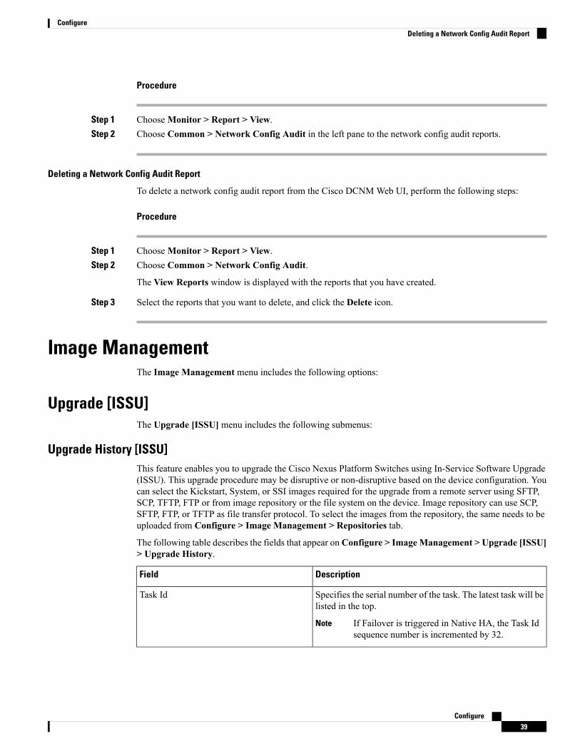
Upgrade History [ISSU]This feature enables you to upgrade the Cisco Nexus Platform Switches using In-Service Software Upgrade(ISSU). This upgrade procedure may be disruptive or non-disruptive based on the device configuration. Youcan select the Kickstart, System, or SSI images required for the upgrade from a remote server using SFTP,SCP, TFTP, FTP or from image repository or the file system on the device. Image repository can use SCP,SFTP, FTP, or TFTP as file transfer protocol. To select the images from the repository, the same needs to beuploaded from Configure > Image Management > Repositories tab.
The following table describes the fields that appear onConfigure > ImageManagement > Upgrade [ISSU]> Upgrade History.
DescriptionField
Specifies the serial number of the task. The latest task will belisted in the top.
If Failover is triggered in Native HA, the Task Idsequence number is incremented by 32.
Note
Task Id
Configure39
ConfigureDeleting a Network Config Audit Report

DescriptionField
Specifies the type of task.
• Compatibility
• Upgrade
Task Type
Based on the Role-Based Authentication Control (RBAC),specifies the owner who initiated this task.
Owner
Displays all the devices that were selected for this task.Devices
Specifies the status of the job.
• Planned
• In Progress
• Completed
• Completed with Exceptions
Job Status
Specifies the time when the task was created.Created Time
Specifies the time when the task is specified to be executed.You can also choose to schedule a task to be executed at alater time.
Scheduled At
Shows any comments that the Owner has added whileperforming the task.
Comment
After a fresh Cisco DCNM installation, this page will have no entries.Note
You can perform the following:
New Installation
To upgrade the devices that are discovered from the Cisco DCNM, perform the following steps:
Procedure
Step 1 Choose Configure > Image Management > Upgrade [ISSU] > Upgrade History, click New Installationto install, or upgrade the kickstart and the system images on the devices.
The devices with default VDCs are displayed in the Select Switches window.
Step 2 Select the check box to the left of the switch name.
You can select more than one device and move the devices to the right column.
Step 3 Click Add or Remove icons to include the appropriate switches for upgrade.
Configure40
ConfigureNew Installation
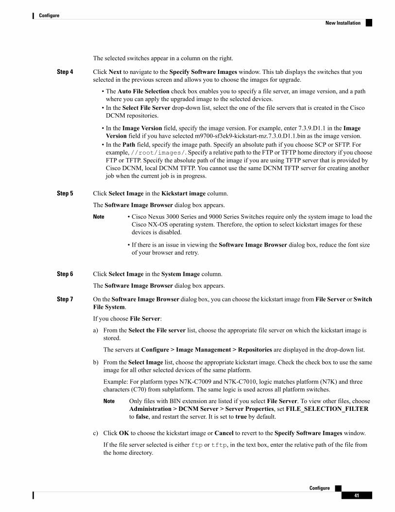
The selected switches appear in a column on the right.
Step 4 Click Next to navigate to the Specify Software Images window. This tab displays the switches that youselected in the previous screen and allows you to choose the images for upgrade.
• The Auto File Selection check box enables you to specify a file server, an image version, and a pathwhere you can apply the upgraded image to the selected devices.
• In the Select File Server drop-down list, select the one of the file servers that is created in the CiscoDCNM repositories.
• In the Image Version field, specify the image version. For example, enter 7.3.9.D1.1 in the ImageVersion field if you have selected m9700-sf3ek9-kickstart-mz.7.3.0.D1.1.bin as the image version.
• In the Path field, specify the image path. Specify an absolute path if you choose SCP or SFTP. Forexample, //root/images/. Specify a relative path to the FTP or TFTP home directory if you chooseFTP or TFTP. Specify the absolute path of the image if you are using TFTP server that is provided byCisco DCNM, local DCNM TFTP. You cannot use the same DCNM TFTP server for creating anotherjob when the current job is in progress.
Step 5 Click Select Image in the Kickstart image column.
The Software Image Browser dialog box appears.
• Cisco Nexus 3000 Series and 9000 Series Switches require only the system image to load theCisco NX-OS operating system. Therefore, the option to select kickstart images for thesedevices is disabled.
• If there is an issue in viewing the Software Image Browser dialog box, reduce the font sizeof your browser and retry.
Note
Step 6 Click Select Image in the System Image column.
The Software Image Browser dialog box appears.
Step 7 On the Software Image Browser dialog box, you can choose the kickstart image from File Server or SwitchFile System.
If you choose File Server:
a) From the Select the File server list, choose the appropriate file server on which the kickstart image isstored.
The servers at Configure > Image Management > Repositories are displayed in the drop-down list.
b) From the Select Image list, choose the appropriate kickstart image. Check the check box to use the sameimage for all other selected devices of the same platform.
Example: For platform types N7K-C7009 and N7K-C7010, logic matches platform (N7K) and threecharacters (C70) from subplatform. The same logic is used across all platform switches.
Only files with BIN extension are listed if you select File Server. To view other files, chooseAdministration > DCNM Server > Server Properties, set FILE_SELECTION_FILTERto false, and restart the server. It is set to true by default.
Note
c) Click OK to choose the kickstart image or Cancel to revert to the Specify Software Images window.
If the file server selected is either ftp or tftp, in the text box, enter the relative path of the file fromthe home directory.
Configure41
ConfigureNew Installation

If you choose Switch File System:
a) From the Select Image list, choose the appropriate image that is located on the flash memory of the device.
Only files with BIN extension are listed if you select Switch File System. To view other files,choose Administration > DCNM Server > Server Properties, setFILE_SELECTION_FILTER to false, and restart the server. It is set to true by default.
Note
b) Click OK to choose the kickstart image or Cancel to revert to the Specify Software Images dialog box.
Step 8 The Vrf column indicates the name of the virtual routing and forwarding (VRF).
VRF is not applicable for Cisco MDS devices.
Step 9 In the Available Space column, specify the available space for the Primary Supervisor and SecondarySupervisor modules of the switch.
Available Space column shows the available memory in MB on the switch (for less than 1 MB, it is shownand marked as KB).
Bootflash browser shows the filename, size, and last modified date for all the files and directories on theswitch bootflash. You can delete files by selecting them and clicking Delete to increase the available spaceon the switch.
Step 10 Selected Files Size column shows the size of images that are selected from the SCP or SFTP server.
If the total size of selected images is greater than available space on a switch, the file size is marked in red.We recommend that you create more space on the switch to copy images to it and install.
Step 11 Drag and drop the switches to reorder the upgrade task sequence.Step 12 Select Skip Version Compatibility if you are sure that the version of the Cisco NX-OS software on your
device is compatible with the upgraded images that you have selected.Step 13 Select Select Parallel Line Card upgrade to upgrade all the line cards at the same time.
Upgrading a parallel line card is not applicable for Cisco MDS devices.
Step 14 Select Options under the Upgrade Options column to choose the type of upgrade.
Upgrade Optionswindow appears with two upgrade options. The drop-down list for Upgrade Option 1 hasthe following options:
• NA
• bios-force
• non-disruptive
NA is the default value.
The drop-down list for Upgrade Option 2 has the following options:
• NA
• bios-force
When NA is selected under Upgrade Option 1, Upgrade Option 2 is disabled.
When bios-force is selected under Upgrade Option 1, Upgrade Option 2 is disabled.
Configure42
ConfigureNew Installation

When non-disruptive is selected underUpgradeOption 1, you can chooseNA or bios-force underUpgradeOption 2.
Check the Use this Option for all other selected devices check box to use the selected option for all theselected devices and click OK.
• The upgrade options are applicable only for Cisco Nexus 3000 Series and 9000 Series switches.
• Selecting the non-disruptive option for upgrading does not ensure a non-disruptive upgrade.Perform a compatibility check to ensure that the device supports non-disruptive upgrade.
Note
Step 15 Click Next.
If you did not select Skip Version Compatibility, the Cisco DCNM performs a compatibility check.
You can choose to wait until the check is complete or click Finish Installation Later.
The installation wizard is closed and a compatibility task is created in Configure > Image Management >Upgrade [ISSU] > Upgrade History tasks.
The time that is taken to check the image compatibility depends on the configuration and the load on thedevice.
The Version Compatibility Verification status column displays the status of verification.
If you skip the version compatibility check by choosing Skip Version Compatibility, Cisco DCNM displaysonly the name of the device, theCurrent Action column displaysCompleted, and theVersion CompatibilityVerification column displays Skipped.
Step 16 Click Finish Installation Later to perform the upgrade later.Step 17 Click Next.Step 18 Check the Next check box to put a device in maintenance mode before upgrade.Step 19 Check the check box to save the running configuration to the startup configuration before upgrading the
device.Step 20 You can schedule the upgrade process to occur immediately or later.
1. Select Deploy Now to upgrade the device immediately.
2. Select Choose time to Deploy and specify the time in MMM/DD/YYYY HH:MM:SS format to performthe upgrade later.
This value is relative to the server time. If the selected time to deploy is in the past, the job is executedimmediately.
Step 21 You can choose the execution mode based on the devices and the line cards you have chosen to upgrade.
1. Select Sequential to upgrade the devices in the order in which they were chosen.
2. Select Concurrent to upgrade all the devices at the same time.
Step 22 Click Finish to begin the upgrade process.
The Installation wizard closes and a task to Upgrade is created on the Configure > Image Management >Upgrade [ISSU] > Upgrade History page.
Configure43
ConfigureNew Installation

Finish Installation
You can choose to complete the installation for tasks which was completed on the Compatibility Checkpage. Perform the following task to complete the upgrade process on the devices.
Procedure
Step 1 Choose Configure > Image Management > Upgrade [ISSU] > Upgrade History, select a task for whichthe compatibility check is complete.
Select only one task at a time.
Step 2 Click Finish Installation.
Software Installation Wizard appears.
Step 3 Check the check box to save the running configuration to the startup configuration before upgrading thedevice.
Step 4 Check the check box to put a device in maintenance mode before upgrade. This option is valid only for thedevices that support maintenance mode.
Step 5 You can schedule the upgrade process to occur immediately or later.
1. Select Deploy Now to upgrade the device immediately.
2. Select Choose time to Deploy and specify the time in DD/MM/YYYY HH:MM:SS format to performthe upgrade later.
Step 6 You can choose the execution mode that is based on the devices and the line cards that you have chosen toupgrade.
1. Select Sequential to upgrade the devices in the order in which they were chosen.
2. Select Concurrent to upgrade the devices at the same time.
Step 7 Click Finish to complete the upgrade process.
View
To view the image upgrade history from the Cisco DCNMWeb UI, perform the following steps:
Procedure
Step 1 Choose Configure > Image Management > Upgrade [ISSU] > Upgrade History, check the task ID checkbox.
Select only one task at a time.
Step 2 Click View.
The Installation Task Details window is displayed.
Step 3 Click Settings. Select Columns and choose the column details options.
Configure44
ConfigureFinish Installation

This window displays the location of the kickstart and system images, compatibility check status, installationstatus, descriptions, and logs.
Step 4 Select the device.
The detailed status of the task is displayed. For the completed tasks, the response from the device is displayed.
If the upgrade task is in progress, a live log of the installation process appears.
This table is refreshed every 30 secs for jobs in progress, when you are on this window.
The switch-level status for an ongoing upgrade on a Cisco MDS switch is not displayed for otherusers without SAN credentials applied. To apply SAN Credentials, choose Administration >Credentials Management > SAN Credentials.
Note
Delete
To delete a task from the Cisco DCNMWeb UI, perform the following steps:
Procedure
Step 1 Choose Configure > Image Management > Upgrade [ISSU] > Upgrade History, and check the Task IDcheck box.
Step 2 Click Delete.Step 3 Click OK to confirm deletion of the job.
Switch Level HistoryYou can view the history of the upgrade process at a switch level. You can view the current version of theswitch and other details.
The following table describes the fields that appear onConfigure > ImageManagement > Upgrade [ISSU]> Switch Level History.
DescriptionField
Specifies the name of the switchSwitch Name
Specifies the IP Address of the switchIP Address
Specifies the Cisco Nexus switch platformPlatform
Specifies the current version on the switch softwareCurrent Version
Click the radio button next to a switch name to select the switch and view its upgrade history. Click View toview the upgrade task history for the selected switch.
The following table describes the fields that appear onConfigure > ImageManagement > Upgrade [ISSU]> Switch Level History > View Device Upgrade Tasks:
Configure45
ConfigureDelete
DescriptionField
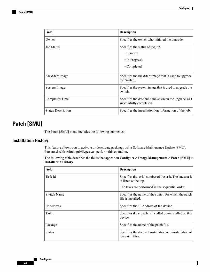
Specifies the owner who initiated the upgrade.Owner
Specifies the status of the job.
• Planned
• In Progress
• Completed
Job Status
Specifies the kickStart image that is used to upgradethe Switch.
KickStart Image
Specifies the system image that is used to upgrade theswitch.
System Image
Specifies the date and time at which the upgrade wassuccessfully completed.
Completed Time
Specifies the installation log information of the job.Status Description
Patch [SMU]The Patch [SMU] menu includes the following submenus:
Installation HistoryThis feature allows you to activate or deactivate packages using Software Maintenance Update (SMU).Personnel with Admin privileges can perform this operation.
The following table describes the fields that appear on Configure > Image Management > Patch [SMU] >Installation History.
DescriptionField
Specifies the serial number of the task. The latest taskis listed at the top.
The tasks are performed in the sequential order.
Task Id
Specifies the name of the switch for which the patchfile is installed.
Switch Name
Specifies the IP Address of the device.IP Address
Specifies if the patch is installed or uninstalled on thisdevice.
Task
Specifies the name of the patch file.Package
Specifies the status of installation or uninstallation ofthe patch files.
Status
Configure46
ConfigurePatch [SMU]
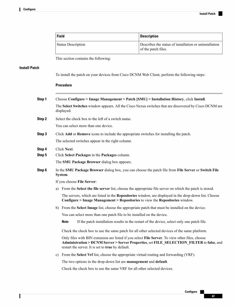
DescriptionField
Describes the status of installation or uninstallationof the patch files.
Status Description
This section contains the following:
Install Patch
To install the patch on your devices from Cisco DCNMWeb Client, perform the following steps:
Procedure
Step 1 Choose Configure > Image Management > Patch [SMU] > Installation History, click Install.
The Select Switches window appears. All the Cisco Nexus switches that are discovered by Cisco DCNM aredisplayed.
Step 2 Select the check box to the left of a switch name.
You can select more than one device.
Step 3 Click Add or Remove icons to include the appropriate switches for installing the patch.
The selected switches appear in the right column.
Step 4 Click Next.Step 5 Click Select Packages in the Packages column.
The SMU Package Browser dialog box appears.
Step 6 In the SMU Package Browser dialog box, you can choose the patch file from File Server or Switch FileSystem.
If you choose File Server:
a) From the Select the file server list, choose the appropriate file server on which the patch is stored.
The servers, which are listed in the Repositories window, are displayed in the drop-down list. ChooseConfigure > Image Management > Repositories to view the Repositories window.
b) From the Select Image list, choose the appropriate patch that must be installed on the device.
You can select more than one patch file to be installed on the device.
If the patch installation results in the restart of the device, select only one patch file.Note
Check the check box to use the same patch for all other selected devices of the same platform.
Only files with BIN extension are listed if you select File Server. To view other files, chooseAdministration > DCNMServer > Server Properties, set FILE_SELECTION_FILTER to false, andrestart the server. It is set to true by default.
c) From the Select Vrf list, choose the appropriate virtual routing and forwarding (VRF).
The two options in the drop-down list aremanagement and default.
Check the check box to use the same VRF for all other selected devices.
Configure47
ConfigureInstall Patch

d) Click OK to choose the patch image or Cancel to revert to the SMU installation wizard.
If you choose Switch File System:
a) From the Select Image list, choose the appropriate patch file image that is located on the flash memoryof the device.
You can select more than one patch file to be installed on the device.
Only files with BIN extension are listed if you select Switch File System. To view other files, chooseAdministration > DCNMServer > Server Properties, set FILE_SELECTION_FILTER to false, andrestart the server. It is set to true by default.
b) Click OK to choose the image, Clear Selections to uncheck all the check boxes, or Cancel to revert tothe SMU Package Browser dialog box.
Step 7 Click Finish.
You will get a confirmation window. Click OK.
SMU installation may reload the switch if the SMU is reloaded.Note
You can view the list of patches that are installed on the switch in the Switches window by choosing DCNM> Inventory > Switches.
Uninstall Patch
To uninstall the patch on your devices from Cisco DCNMWeb Client, perform the following steps:
Procedure
Step 1 Choose Configure > Image Management > Patch [SMU] > Installation History, click Uninstall.
The Select Switches page appears. The discovered Cisco Nexus switches are displayed.
Step 2 Check the check box on the left of the switch name.
You can select more than one image device.
Step 3 Click Add or Remove icons to include the appropriate switches for installing the patch.
The selected switches appear in a column on the right.
Step 4 Click Next.
The Active Packages page appears.
Step 5 Click Select Packages under the Installed Packages column.
The Packages Installed window appears, which lists the patches that are applied to the switch.
Step 6 Select the patches that you want to uninstall from this device.
You can select more than one patch that is applied on the device.
If the patch uninstallation results in the restart of the device, select only one patch.Note
Configure48
ConfigureUninstall Patch

Step 7 Click Finish to uninstall the patch from the device.
You will get a confirmation window. Click OK.
You can uninstall more than one patch at a time.
SMU uninstallation may reload the switch if the SMU is reloaded.Note
Delete Patch Installation Tasks
To delete the patch installation tasks from the Cisco DCNMWeb UI, perform the following steps:
Procedure
Step 1 Choose Configure > Image Management > Patch [SMU] > Installation History, check the task ID checkbox.
Step 2 Click Delete.Step 3 Click OK to confirm deletion of the patch installation task.
Switch Installed PatchesYou can view the patches that are installed on all the switches in the network. You can refresh the view tosee the latest installed patches.
The following table describes the fields that appear on Configure > Image Management > Patch [SMU] >Switch Installed Patches.
DescriptionField
Specifies the name of the switch.Switch Name
Specifies the IP address of the switch.IP Address
Specifies the Cisco Nexus switch platform.Platform
Specifies the currently installed patches on switches.Installed Patches
Click Refresh to refresh the table.
Package [RPM]The Package [RPM] menu includes the following submenus:
Package Installation [RPM]The package [RPM] feature allows you to install RPM packages. This feature is available for the Cisco Nexus9000 Series and 3000 Series Switches.
Configure49
ConfigureDelete Patch Installation Tasks

The following table describes the fields that appear on Configure > Image Management > Package [RPM]> Installation History.
DescriptionField
Specifies the serial number of the task. The latest taskis listed in the top.
The tasks are performed in the sequential order.
Task Id
Specifies the name of the switch for which thepackage file is installed.
Switch Name
Specifies the IP address of the device.IPAddress
Specifies if the package is installed or uninstalled onthis device.
Task
Specifies the name of the package file.Package
Specifies the status of installation or uninstallation ofthe package files.
Status
Specifies the time at which the installation oruninstallation task completed.
Completed Time
Describes the status of installation or uninstallationof the package files.
Status Description
This section contains the following:
Install Package [RPM]
Perform the following task to install the package on your devices using Cisco DCNMWeb client.
Procedure
Step 1 Choose Configure > Image Management > Package [RPM] > Installation History, click Install.
The Select Switches page appears.
Step 2 Check the check box on the left of the switch name.
You can select more than one device.
Step 3 Click Add or Remove to include appropriate switches for installing packaging.
The selected switches appear in a column on the right.
Step 4 Click Next.Step 5 Click Select Packages in the Packages column.
The RPM Package Browser screen appears.
Step 6 Choose the package file from File Server or Switch File System.
Configure50
ConfigureInstall Package [RPM]

If you choose File Server:
a) From the Select the file server list, choose the appropriate file server on which the package is stored.
The servers at Configure > Image Management > Repositories are displayed in the drop-down list.
b) From the Select Image list, choose the appropriate package that must be installed on the device.
You can select more than one package file to be installed on the device.
Only files with RPM extension are listed if you select File Server. To view other files, chooseAdministration > DCNMServer > Server Properties, set FILE_SELECTION_FILTER to false, andrestart the server. It is set to true by default.
Check the check box to use the same package for all other selected devices of the same platform.
c) Click OK to choose the patch image or Cancel to revert to the RPM Installation Wizard.
If you choose Switch File System:
a) From the Select Image list, choose the appropriate package file image that is located on the flash memoryof the device.
You can select more than one package file to be installed on the device.
Only files with RPM extension are listed if you select Switch File System. To view other files, chooseAdministration > DCNMServer > Server Properties, set FILE_SELECTION_FILTER to false, andrestart the server. It is set to true by default.
b) Click OK.
Step 7 In the Installation Type column, choose one of the installation types:
• Normal—Fresh installation• Upgrade—Upgrading the existing RPM• Downgrade—Downgrading the existing RPM
Step 8 Click Finish.
You can view the list of packages that are installed on the switch, on theWeb Client > Inventory > Switchespage.
If you are using Cisco DCNM Release 10.1(2), in case of installation of reload RPMs, perform amanual install commit on the switch after it switch reloads.
Note
Uninstall Package [RPM]
To uninstall the RPM on your devices from the Cisco DCNMWeb UI, perform the following steps:
Procedure
Step 1 Choose Configure > Image Management > Package [RPM] > Installation History, click Uninstall.
The Select Switches window appears.
Step 2 Check the check box on the left of the switch name.
Configure51
ConfigureUninstall Package [RPM]

You can select more than one switch.
Step 3 Click the Add or Remove icons to include the appropriate switches for uninstalling the package.
The selected switches appear in a column on the right.
Step 4 Click Next.
The Active Packages page appears.
Step 5 Click Select Packages under the Installed Packages column.
The Packages Installed window appears, which lists the packages that are installed in the switch.
Step 6 Click Finish to uninstall the package from the device.
You will get a confirmation window. Click OK.
You can uninstall more than one package at a time.
• If you are using Cisco DCNM Release 10.1(2), in case of uninstallation of reload RPMs, amanual install commit needs to be performed on the switch once the switch is reloaded.
• RPM uninstallation may reload the switch if the RPM is reload RPM.
Note
Delete Package Installation Tasks
To delete the package installation tasks from the history view from the Cisco DCNMWeb UI, perform thefollowing steps:
Procedure
Step 1 Choose Configure > Image Management > Package [RPM] > Installation History, select the task IDcheck box.
Step 2 Click Delete.Step 3 Click OK to confirm deletion of the task.
Switch Installed PackagesYou can view the RPM packages that are installed on all Switches in the network. You can refresh the viewto see the latest installed packages.
The following table describes the fields that appear onConfigure > ImageManagement > Packages [RPM]> Switch Installed Packages.
DescriptionField
Specifies the name of the switch.Switch Name
Specifies the IP address of the switch.IP Address
Configure52
ConfigureDelete Package Installation Tasks

DescriptionField
Specifies the Cisco Nexus switch platform.Platform
Specifies the currently installed packages on theswitches and the type of package. The installedpackages can be base packages or non-base packages.
Installed Packages
Click Refresh to refresh the table.
Maintenance Mode [GIR]The Maintenance Mode [GIR] menu includes the following submenus:
Maintenance ModeThe maintenance mode allows you to isolate the Cisco Nexus Switch from the network to perform an upgradeor debug, using Graceful Insertion and Removal (GIR). When the switch maintenance is complete, you canreturn the switch to normal mode. When the switch is in the maintenance mode, all protocols are gracefullybrought down and all physical ports are shut down. When the normal mode is restored, all the protocols andports are initiated again.
Perform the following to change the system mode of the devices.
Procedure
Step 1 Choose Configure > Image Management > Maintenance Mode [GIR] > Maintenance Mode, check theswitch name check box.
You can select multiple switches.
Step 2 Choose one of the following options under theMode Selection column:
• Shutdown
• Isolate
Click the appropriate option before you change the mode.Note
Step 3 Click Change System Mode.
A confirmation message appears.
Step 4 Click OK to confirm to change the maintenance mode of the device.
The status of operation can be viewed in the System Mode and theMaintenance Status.
Switch Maintenance HistoryYou can view the history of the maintenance mode changes executed from the Cisco DCNM.
Configure53
ConfigureMaintenance Mode [GIR]

The following table describes the fields that appear on Configure > Image Management > MaintenanceMode [GIR] > Switch Maintenance History.
DescriptionField
Specifies the serial number of the task. The latest tasksthat are listed in the top.
Task Id
Specifies the name of the switch for which themaintenance mode was changed.
Switch Name
Specifies the IP address of the switch.IP Address
Specifies the name of the user who initiated themaintenance.
User
Specifies the mode of the system.System Mode
Specifies the mode of the maintenance process.Maintenance Status
Specifies the status of the mode change.Status
Specified the time at which the maintenance modeactivity was completed.
Completed Time
Click the radio button next to the switch name to select the switch for which you need to view the upgradehistory. Click View to view the upgrade task history for the selected switch.
The following table describes the fields that appear onConfigure > ImageManagement > Upgrade [ISSU]> Switch Level History > View > Upgrade Tasks History
DescriptionField
Specifies the owner who initiated the upgrade.Owner
Specifies the status of the job.
• Planned
• In Progress
• Completed
Job Status
Specifies the kickstart image that is used to upgradethe Switch.
KickStart Image
Specifies the system image that is used to upgrade theswitch.
System Image
Specifies the date and time at which the upgrade wassuccessfully completed.
Completed Time
Configure54
ConfigureSwitch Maintenance History

RepositoriesThis feature allows you to add image servers and configuration servers information to fetch images for Upgrade,Patch, and POAP mode operations.
You can specify valid servers for SCP/SFTP/FTP/TFTP. DCNM does not perform the validation forSCP/SFTP/FTP/TFTP servers while creating or updating the servers. DCNM performs validation only forthe SCP servers.
The SCP repositories use SSH protocol for the directory listing and therefore you need to enable SSH on theSCP repository server. The SFTP repository uses SFTP protocol for directory listing. The TFTP and FTPrepositories do not support directory listing. You need to specify the file path manually.
Note
Add Image or Configuration Server URLTo add an image or a configuration server URL to the repository from the Cisco DCNMWeb UI, performthe following steps:
Procedure
Step 1 On the Image and Configuration Servers window, click the Add icon.
The Add Image or Configuration Server URL window is displayed.
Step 2 Specify a name for the image.Step 3 Click the radio button to select the protocol.
The available protocols are SCP, FTP, SFTP, and TFTP. Use the SCP protocol for POAP and ImageManagement.
You can use IPv4 and IPv6 addresses with these protocols.
Step 4 Enter the hostname or IP address and the path to download or upload files.Step 5 Specify the username and password.Step 6 Click OK to save.
Deleting an Image or Configuration Server URLTo delete an image from the repository from the Cisco DCNMWeb UI, perform the following steps:
Procedure
Step 1 On the Image and Configuration Servers window, select an existing image from the list, and click Delete.Step 2 In the delete notification, click Yes to delete the image and configuration server.
Configure55
ConfigureRepositories

The default SCP Repository cannot be deleted.Note
Editing an Image or Configuration Server URLTo edit an image or a configuration server URL to the repository from the Cisco DCNMWeb UI, performthe following steps:
Procedure
Step 1 On the Image and Configuration Servers window, select an existing image and configuration server fromthe list, and click Edit.
Step 2 In the Edit Image or Configuration Server URL window, edit the required fields.Step 3 Click OK to save or click Cancel to discard the changes.
File BrowserYou can view the contents of the server on the Image and Configuration Servers page.
1. In the Image and Configurations page, check the Server Name check box to view the content.
2. Click File Browser to view the contents of this server.
Image UploadTo upload different types of images to the server from the Cisco DCNMWeb UI, perform the following steps:
Devices use these images during POAP.Note
Procedure
Step 1 On the Image and Configuration Servers window, check the server name check box to select the server foruploading images.
The Select Image File window appears.
Step 2 Click Browse to select the image file from the directory.Step 3 From the Platform drop-down list, select the device to which you must upload this image.Step 4 From the Type drop-down list, select the type of the image you are uploading to the device.Step 5 Click OK.
The image is uploaded to the repository.
Configure56
ConfigureEditing an Image or Configuration Server URL
SANThe SAN menu includes the following submenus:
VSANsBeginning with Cisco DCNM Release 11, you can configure and manage VSANs from the Cisco DCNM.From the menu bar, chooseConfigure > SAN >VSAN to viewVSAN information. You can view or configureVSAN for the discovered fabrics, with eitherManageable orManage Continuously status. For the selectedfabric, a VSAN Scope tree is displayed in the left panel.
You can achieve higher security and greater stability in Fibre Channel fabrics by using virtual SANs (VSANs)on Cisco Data Center Switches and Cisco MDS 9000 Family switches. VSANs provide isolation amongdevices that are physically connected to the same fabric. With VSANs, you can create multiple logical SANsover a common physical infrastructure. Each VSAN can contain up to 239 switches and has an independentaddress space that allows identical Fibre Channel IDs (FC IDs) to be used simultaneously in different VSANs.
Cisco DCNM does not discover, nor display any suspended VSAN.Note
The information that is associated with the selected VSAN scope appears in the right panel. If a VSAN issegmented, each individual segmented VSAN is a VSAN scope. For every selected VSAN scope, you canview information in tabs.
• Switches tab
• ISLs Tab
• Host Ports Tab
• Storage Tab
• Attributes Tab
• Domain ID Tab
• VSAN Membership Tab
For description on all fields that appear on the tabs, refer Field and Descriptions for VSANs, on page 65.
Information About VSANsWith the introduction of VSANs, the network administrator can build a single topology containing switches,links, and one or more VSANs. Each VSAN in this topology has the same behavior and property of a SAN.A VSAN has the following additional features:
• Multiple VSANs can share the same physical topology.
• The same Fibre Channel IDs (FC IDs) can be assigned to a host in another VSAN, thus increasing VSANscalability.
• Every instance of a VSAN runs all required protocols such as FSPF, domain manager, and zoning.
Configure57
ConfigureSAN

• Fabric-related configurations in one VSAN do not affect the associated traffic in another VSAN.
• Events causing traffic disruptions in one VSAN are contained within that VSAN and are not propagatedto other VSANs.
A VSAN is in the operational state if the VSAN is active and at least one port is up. This state indicates thattraffic can pass through this VSAN. This state cannot be configured.
Interoperability enables the products of multiple vendors to come into contact with each other. Fibre Channelstandards guide vendors towards common external Fibre Channel interfaces. You can enable FICON in upto eight VSANs.
This section describes VSANs and includes the following topics:
VSAN Topologies
The following figure shows a fabric with three switches, one on each floor. The geographic location of theswitches and the attached devices is independent of their segmentation into logical VSANs. No communicationbetween VSANs is possible. Within each VSAN, all members can talk to one another.Figure 1: Logical VSAN Segmentation – 79532.ps
The following shows a physical Fibre Channel switching infrastructure with two defined VSANs: VSAN 2(dashed) and VSAN 7 (solid). VSAN 2 includes hosts H1 and H2, application servers AS2 and AS3, andstorage arrays SA1 and SA4. VSAN 7 connects H3, AS1, SA2, and SA3.Figure 2: Example of Two VSANs – 79533.ps
The four switches in this network are interconnected by trunk links that carry both VSAN 2 and VSAN 7traffic. The inter-switch topology of both VSAN 2 and VSAN 7 are identical. This is not a requirement anda network administrator can enable certain VSANs on certain links to create different VSAN topologies.
Without VSANs, a network administrator would need separate switches and links for separate SANs. Byenabling VSANs, the same switches and links may be shared by multiple VSANs. VSANs allow SANs to bebuilt on port granularity instead of switch granularity. Figure 1-2 illustrates that a VSAN is a group of hostsor storage devices that communicate with each other using a virtual topology defined on the physical SAN.
The criteria for creating such groups differ based on the VSAN topology:
• VSANs can separate traffic based on the following requirements:
• Different customers in storage provider data centers
• Production or test in an enterprise network
• Low and high security requirements
• Back up traffic on separate VSANs
• Replicating data from user traffic
• VSANs can meet the needs of a particular department or application.
VSAN Advantages
VSANs offer the following advantages:
• Traffic isolation—Traffic is contained within VSAN boundaries and devices reside only in one VSANensuring absolute separation between user groups, if desired.
Configure58
ConfigureVSAN Topologies

• Scalability—VSANs are overlaid on top of a single physical fabric. The ability to create several logicalVSAN layers increases the scalability of the SAN.
• Per VSAN fabric services—Replication of fabric services on a per VSAN basis provides increasedscalability and availability.
• Redundancy—Several VSANs created on the same physical SAN ensure redundancy. If one VSAN fails,redundant protection (to another VSAN in the same physical SAN) is configured using a backup pathbetween the host and the device.
• Ease of configuration—Users can be added, moved, or changed between VSANs without changing thephysical structure of a SAN. Moving a device from one VSAN to another only requires configuration atthe port level, not at a physical level.
Up to 256 VSANs can be configured in a switch. Of these, one is a default VSAN (VSAN 1), and another isan isolated VSAN (VSAN 4094). User-specified VSAN IDs range from 2 to 4093.
VSAN Configuration
VSANs have the following attributes:
• VSAN ID—The VSAN ID identifies the VSAN as the default VSAN (VSAN 1), user-defined VSANs(VSAN 2 to 4093), and the isolated VSAN (VSAN 4094).
• State—The administrative state of a VSAN can be configured to an active (default) or suspended state.Once VSANs are created, they may exist in various conditions or states.
• The active state of a VSAN indicates that the VSAN is configured and enabled. By enabling aVSAN, you activate the services for that VSAN.
• The suspended state of a VSAN indicates that the VSAN is configured but not enabled. If a port isconfigured in this VSAN, it is disabled. Use this state to deactivate a VSAN without losing theVSAN’s configuration. All ports in a suspended VSAN are disabled. By suspending a VSAN, youcan preconfigure all the VSAN parameters for the whole fabric and activate the VSAN immediately.
• VSAN name—This text string identifies the VSAN for management purposes. The name can be from 1to 32 characters long and it must be unique across all VSANs. By default, the VSAN name is aconcatenation of VSAN and a four-digit string representing the VSAN ID. For example, the default namefor VSAN 3 is VSAN0003.
A VSAN name must be unique.Note
• Load balancing attributes—These attributes indicate the use of the source-destination ID (src-dst-id) orthe originator exchange OX ID (src-dst-ox-id, the default) for load balancing path selection.
OX ID-based load balancing of IVR traffic from IVR-enabled switches is notsupported on Generation 1 switching modules. OX ID-based load balancing ofIVR traffic from a non-IVR MDS 9000 Family switch should work. Generation2 switching modules support OX ID-based load balancing of IVR traffic fromIVR-enabled switches.
Note
Configure59
ConfigureVSAN Configuration

• Load balancing attributes indicate the use of the source-destination ID (src-dst-id) or the originatorexchange OX ID (src-dst-ox-id, the default) for load balancing path selection.
Port VSAN Membership
Port VSAN membership on the switch is assigned on a port-by-port basis. By default, each port belongs tothe default VSAN. You can assign VSAN membership to ports using one of two methods:
• Statically—By assigning VSANs to ports.
• Dynamically—By assigning VSANs based on the device WWN. This method is referred to as dynamicport VSAN membership (DPVM).
Types of VSAN
The following are the different types of VSAN:
Default VSAN
The factory settings for switches in the Cisco MDS 9000 Family have only the default VSAN 1 enabled. Werecommend that you do not use VSAN 1 as your production environment VSAN. If no VSANs are configured,all devices in the fabric are considered part of the default VSAN. By default, all ports are assigned to thedefault VSAN.
VSAN 1 cannot be deleted, but it can be suspended.Note
Up to 256 VSANs can be configured in a switch. Of these, one is a default VSAN (VSAN 1), and another isan isolated VSAN (VSAN 4094). User-specified VSAN IDs range from 2 to 4093.
Isolated VSAN
VSAN 4094 is an isolated VSAN. All non-trunking ports are transferred to this VSAN when the VSAN towhich they belong is deleted. This avoids an implicit transfer of ports to the default VSAN or to anotherconfigured VSAN. All ports in the deleted VSAN are isolated (disabled).
When you configure a port in VSAN 4094 or move a port to VSAN 4094, that port is immediately isolated.Note
Do not use an isolated VSAN to configure ports.Caution
Up to 256 VSANs can be configured in a switch. Of these, one is a default VSAN (VSAN 1), and another isan isolated VSAN (VSAN 4094). User-specified VSAN IDs range from 2 to 4093.
Static VSAN Deletion
When an active VSAN is deleted, all of its attributes are removed from the running configuration. VSAN-relatedinformation is maintained by the system software as follows:
Configure60
ConfigurePort VSAN Membership

• VSAN attributes and port membership details are maintained by the VSAN manager. This feature isaffected when you delete a VSAN from the configuration. When a VSAN is deleted, all the ports in thatVSAN are made inactive and the ports are moved to the isolated VSAN. If the same VSAN is recreated,the ports do not automatically get assigned to that VSAN. Youmust explicitly reconfigure the port VSANmembership (see the following figure).Figure 3: VSAN Port Membership Details – 79947.ps
• VSAN-based runtime (name server), zoning, and configuration (static routes) information is removedwhen the VSAN is deleted.
• Configured VSAN interface information is removed when the VSAN is deleted.
The allowed VSAN list is not affected when a VSAN is deleted.Note
Any commands for a non-configured VSAN are rejected. For example, if VSAN 10 is not configured in thesystem, then a command request to move a port to VSAN 10 is rejected.
Feature Information for Configuring and Managing VSANsThe following table shows the licensing requirements for this feature:
License License Description
ENTERPRISE_PKG The enterprise license is required to enable VSAN. For a complete explanation of thelicensing scheme, see the Cisco DCNM Licensing Guide.
License DescriptionLicense
The enterprise license is required to enable VSAN.For a complete explanation of the licensing scheme,see the Cisco DCNM Licensing Guide.
ENTERPRISE_PKG
Configure61
ConfigureFeature Information for Configuring and Managing VSANs

Default VSAN SettingsThe following table lists the default settings for all configured VSANs.
DefaultParameters
VSAN 1.Default VSAN
Active StateState
Concatenation of VSAN and a four-digit stringrepresenting the VSAN ID. For example, VSAN 3 isVSAN0003.
Name
OX ID (src-dst-ox-id).Load-balancing attribute
Create VSAN WizardVSAN Creation Wizard Work flow includes:
• Specify VSAN ID and name.
• Select Switches.
• Specify VSAN attributes.
• Specify VSAN Domain.
• Specify VSAN Members.
Beginning with Release 11, you can configure VSAN using a wizard that facilitates creating VSANs onmultiple switches in a managed Fabric. Choose Configure > SAN > VSAN. After you select a Fabric fromthe drop-down list, click Create VSANWizard icon. The Welcome screen of the wizard is displayed.
Ensure that the VSAN is not already created.Note
Ensure that you provide Switch credentials, if you are different from the Discover user. To provide SANcredentials, navigate to Administration > Credentials Management > SAN Credentials.
Note
To create and configure VSANs from the Cisco DCNMWeb UI, perform the following steps:
Before you begin
You cannot configure any application-specific parameters for a VSAN before creating the VSAN.
Ensure that the VSAN is not already created. Do not create the VSAN in suspended state.
The suspended VSANs are not managed.Note
Configure62
ConfigureDefault VSAN Settings

Procedure
Step 1 On the Create VSAN Wizard Welcome screen, click Next.
The Select VSAN ID and Name window is displayed.
Step 2 In the Select VSAN ID and Name window, perform the following steps:a) Ensure that the correct Fabric is against the Fabric field.b) In the VSAN ID field, select VSAN ID from the drop-down list.
The range is from 2 to 4094 for the list of VSAN ID that is available to be created in at least one Switchin the Fabric. VSAN ID 4079 is for reserved VSAN.
c) In the Name field, enter a name for VSAN.
If the field is left blank, the Switch assigns a default name to the VSAN.Note
d) Click FICON checkbox to enable FICON on the switch.e) Click Next.
Step 3 In the Select Switches screen, click the checkbox next to the Switch Name, to create the VSAN.
If the switch name is grayed out, it implies that the switch is already a part of VSAN. It may also imply thatthe switch does not have FICON feature enabled, if FICON is checked in the previous step.
Click Next.
Step 4 In the Config VSAN Attributes screen, configure the VSAN attributes.
If you create a VSAN in a suspended state, it will not appear on the Cisco DCNM as DCNM doesnot manage suspended VSANs.
Note
a) In the LoadBalancing, select the load balancing type to be used on the VSAN.
The following types are available:
• srcIdDestId: based on only source ID (S_ID) and destination ID (D_ID).
• srcIdDestIdOxId: Originator exchange ID (OX_ID) is also used for load balancing in addition toS_ID and D_ID. OX_ID is an exchange ID assigned by the originator Interconnect Port for anexchange with the target Interconnect Port.
srcId/DestId/OxId is the default for non-FICONVSAN and it is not available for FICONVSAN,srcId/DestId is the default for FICON VSAN.
Note
b) In the InterOp field, select the interoperability value the drop-down list.
The InterOp value is used to interoperate with different vendor devices. You can choose from one of thefollowing:
• 0: implies that the interoperability is disabled.
• 1: implies that the VSAN can interoperate with all the Fibre Channel vendor devices.
• 2: implies that the VSAN can interoperate with specific Fibre Channel vendor devices for basic toadvanced functionalities.
• 3: implies that the VSAN can interoperate with specific Fibre Channel vendor devices for basic toadvanced functionalities.
Configure63
ConfigureCreate VSAN Wizard

• 4: implies that the VSAN can interoperate with specific Fibre Channel vendor devices for basic toadvanced functionalities.
InterOp is not supported on FICON VSAN.Note
c) In the Admin State field, select the configurable state for this VSAN.
• active: implies that the VSAN is configured and services for this VSAN is activated.
• suspended: implies that the VSAN is configured, but the service for this VSAN is deactivated.
Choose this state to preconfigure all the VSAN parameters for the whole Fabric.
DCNM does not manage a suspended VSAN, and therefore it will not appear in the VSANscope.
Note
d) Check the Inorder Delivery checkbox to allow in-order delivery.
When the value of fcInorderDelivery is changed, the value of this object is set to the new value of thatobject.
e) In the Add Fabric Binding DB field, check the checkbox if you want to enable the fabric binding for theFICON VSAN.
If the checkbox is selected, the all the peers in the selected switches are added to each switch in the selectedlist.
f) In the All Port Prohibited field, check the checkbox if you want to prohibit all the ports for FICONVSAN.
If the checkbox is selected, the FICON VSAN is created as all Ports prohibited, by default.
g) Click Next.
Step 5 In the Config VSAN Domain screen, configure the static domain IDs for FICON VSAN.a) Select the Use Static Domain IDs field, to configure the domain ID for the switches in the VSAN.b) The Available Domain IDs field shows all the available Domain IDs in the Fabric.
Click Apply Available Domain IDs to assign the domain ID for every switch that is selected to be a partof the VSAN.
c) For every switch in the table, enter the domain ID from the list of available Domain IDs.d) Click Next.
Step 6 In the Config Port VSANMembership screen, for every switch in the VSAN, configure the interfaces, as themember of the new VSAN.
Modifying the Port VSAN may affect the I/O of the interface.Note
Click Next.
Step 7 In the Summary screen, verify if you have configured the VSAN correctly.
Click Previous to navigate to the earlier screen and modify the configuration.
Click Cancel to discard the configuration.
Click Finish to confirm and configure the VSAN. The VSAN creation result is displayed at the bottom of thewindow.
Configure64
ConfigureCreate VSAN Wizard
After the VSAN is created, it will take fewminutes for the newVSAN to appear in the VSAN scopetree.
Note
Delete VSANTo delete a VSAN and its attributes from the Cisco DCNMWeb UI, perform the following steps:
Procedure
Step 1 Choose Configure > SAN > VSAN.
The VSAN window is displayed.
Step 2 From the Fabric drop-down list, select the Fabric to which the VSAN is associated.
The VSAN scope tree for the selected Fabric is displayed in the VSAN area.
Step 3 Expand the Fabric and select the VSAN that you want to delete.
You cannot delete Segmented VSAN.Note
Step 4 Click the Delete VSAN icon.
The Delete VSAN screen appears, showing the switches associated with the VSAN.
Step 5 Select the checkbox of the Switch for which you want to remove the VSAN.
Click Delete.
A confirmation window appears.
Step 6 Click Yes to confirm the deletion or click No to close the dialog box without deleting the VSAN.
After the VSAN is deleted, it will take few minutes for the new VSAN to disappear from the VSANscope tree.
Note
Field and Descriptions for VSANsThe Field and Descriptions for all the tabs that are displayed onCiscoWeb UI > SAN > VSAN are explainedin the following tables.
• Switches tab, on page 66
• ISLs Tab, on page 66
• Host Ports Tab, on page 67
• Storage Tab, on page 67
• Attributes Tab, on page 68
• Domain ID Tab, on page 69
Configure65
ConfigureDelete VSAN

• VSAN Membership Tab, on page 70
Switches tab
This tab displays Switches in the VSAN scope. Click the Switch name to view the summary information ofthe switch. The following table describes the fields that appear on the Switches tab.
Table 8: Field and Description on Switches Tab
DescriptionField
Specifies the name of the switch in the VSAN.
Click the name to view the switch summary. For description about the fields in the SwitchSummary, refer to Viewing Inventory Information for Switches.
Click Show more Details to view complete information.
Name
Specifies an insistent domain ID.Domain ID
Specifies the WorldWide Name (WWN) of the VSAN.VSAN WWN
Specifies the WorldWide Name (WWN) of the switch.
For the principal switch, the value is "self".Note
PrincipalWWN
Specifies the model name of the switch.Model
Specifies the NX-OS version on the switch.Release
Specifies the time from which the switch is up.Uptime
Icons
The number next to Total specifies the entries under this tab.Total
Click the Refresh icon to refresh the entries.Refresh
ISLs Tab
This tab displays information about the ISLs about the switches in the VSAN scope. Click the Switch nameto view the summary information. Click Show more details to view complete information on the selectedswitch. The following table describes the fields that appear on the ISLs tab.
Table 9: Field and Description on ISLs Tab
DescriptionField
All VSANs which this ISL runs traffic on.VSANs
The source switch of the link.From Switch
The port index of source E_port of the link.From Interface
The switch on the other end of the link.To Switch
The port index of destination E_port of the link.To Interface
The speed of this ISL.Speed
Configure66
ConfigureField and Descriptions for VSANs

DescriptionField
The operational status of the link.Status
The member of Port Channel if ISL is a Port Channel.Port ChannelMembers
Additional information for this ISL, e.g., TE/TF/TNP ISLAdditional Info
Icons
The number next to Total specifies the entries under this tab.Total
Click the Refresh icon to refresh the entries.Refresh Icon
Host Ports Tab
This tab displays information about the host ports on the switches in the VSAN scope. The following tabledescribes the fields that appear on the Host Ports tab.
Table 10: Field and Description on Host Ports Tab
DescriptionField
The name of the enclosure.Enclosure
The device alias of this entry.device Alias
The assigned PWWN for this host.Port WWN
The FC ID assigned for this host.FcId
Interface on the switch that is connected with the end device.SwitchInterface
The operational status of the link.Link Status
Specifies the name of the vendor.Vendor
Specifies the name of the model.Model
The version of the firmware that is executed by this HBA.Firmware
The version of the driver that is executed by this HBA.Driver
The information list corresponding to this HBA.Additional Info
Icons
The number next to Total specifies the entries under this tab.Total
Click the Refresh icon to refresh the entries.Refresh
Storage Tab
This tab displays information about the storage ports on the switches in the VSAN scope. The following tabledescribes the fields that appear on the Storage Ports tab.
Configure67
ConfigureField and Descriptions for VSANs

Table 11: Field and Description on Storage Tab
DescriptionField
The name of the enclosure.Enclosure
The device alias of this entry.device Alias
The assigned PWWN for this host.Port WWN
The FC ID assigned for this host.FcId
Interface on the switch that is connected with the end device.SwitchInterface
The operational status of the link.Link Status
Icons
The number next to Table specifies the entries under this tab.Total
Click the Refresh icon to refresh the entries.Refresh
Attributes Tab
This tab displays the attributes of all the switches in the VSAN scope. The following table describes the fieldsthat appear on the Attributes tab.
Table 12: Field and Description on Attributes Tab
DescriptionField
Click Edit to modify the attributes of the VSAN and to push the same VSAN attributes tothe selected switches.
If the VSAN is FICON VSAN in any selected switch, the following fields will not appearon the UI, as they cannot be modified for the FICON VSAN.
• Load-balancing
• InterOp
• InorderDelivery
After modify the attributes, you can click Apply to save changes or Cancel to discard.
Edit
Displays the name of the switch that is associated with the VSAN.Switch Name
Displays the name of the VSAN.Name
Specifies if the status of the Admin is either Active or Suspend.
• active implies that the VSAN is configured and services for the VSAN is activated.
• suspended implies that the VSAN is configured; however, the service for the VSANis deactivated. You can use set this state to preconfigure all the VSAN parameters byusing the CLI only.
If you suspend a VSAN, it is removed from Cisco DCNM as well.Note
Admin
Configure68
ConfigureField and Descriptions for VSANs

DescriptionField
The operational state of the VSAN.Oper
Displays the MTU for the switch.MTU
Specifies the load balancing type that is used in the VSAN.
The type of load balancing used on this VSAN.
• srcId/DestId—use source and destination ID for path selection
• srcdId/DestId/0xld—use source, destination, and exchange IDs
LoadBalancing
The interoperability mode of the local switch on this VSAN.
• standard
• interop-1
• interop-2
• interop-3
InterOp
The InorderDelivery guarantee flag of device. If true, then the inorder delivery is guaranteed.If false, it is not guaranteed.
InorderDelivery
True if the VSAN is FICON-enabled.FICON
Icons
The number next to Table specifies the entries under this tab.Total
Click the Refresh icon to refresh the entries.Refresh Icon
Domain ID Tab
This tab displays information about the VSAN domain and its parameters. The following table describes thefields that appear on the Domain ID tab.
Table 13: Field and Description on Domain ID Tab
DescriptionField
Click Edit icon to modify the Domain ID information for the selected switch.Edit
Specifies the switch name in the VSAN.
NPV switches are not listed in this column. However, the NPV switches exist inthis VSAN fabric.
Note
SwitchName
Specifies the state of the Switch.State
Specifies if the Domain ID is enabled or disabled.Enable
Specifies the running domain.Running
Specifies the usage of the domain ID type—preferred or static.ConfigType
Configure69
ConfigureField and Descriptions for VSANs

DescriptionField
Icons
The number next to Table specifies the entries under this tab.Total
Click the Refresh icon to refresh the entries.RefreshIcon
VSAN Membership Tab
This tab displays information about the interfaces on the switches that form the VSAN. The following tabledescribes the fields that appear on the VSAN Membership tab.
Table 14: Field and Description on VSAN Membership Tab
DescriptionField
Click Edit icon to modify Port VSAN Membership for selected VSAN and selected switch.
Port VSANMembership is presented by different types including FC (physical), PortChannel,FCIP, iSCSI, VFC (slot/port), VFC (ID), VFC (Channel), VFC FEX, and VFC Breakout,PortChooser is provided for each type to show all existing interfaces on a selected switch forthe user to choose from.
If you modify Post VSAN Membership for any operational trunking port or portchannel members, a warning appears. Use the Device Manager to change AllowedVSAN List for Trunking Interface.
Note
Edit
Name of the switchSwitchName
FC Ports in VSANInterfaces
Icons
The number next to Table specifies the entries under this tab.Total
Click the Refresh icon to refresh the entries.RefreshIcon
SAN ZoningZoning enables you to set up access control between storage devices or user groups. If you have administratorprivileges in your fabric, you can create zones to increase the network security and to prevent data loss orcorruption. Zoning is enforced by examining the source-destination ID field.
The following table describes the fields and icons that appear on Cisco DCNM Configure > SAN > Zoningtab.
DescriptionField
From the Fabric drop-down list, you can choose thefabric for which you are configuring or viewing theSAN Zoning.
Fabric
Configure70
ConfigureSAN Zoning

DescriptionField
From the VSAN drop-down list, you can choose theVSAN for which you are configuring zoning.
VSAN
From the Switch drop-down list, select the switch towhich you want to configure.
Switches
Commits the Zoning configuration changes to all theswitches. This field is only applicable when a zone isin the enhanced or smart mode.
Commit Changes
Distributes the Zoning configuration to all theswitches. This field is only applicable when a zone isin the basic mode.
Distribute
You can export the Zoning configurations to a .csvfile, and save it on your local directory.
Export All
Lists all the Zoneset configured for the selectedFabric, VSAN, and the Switch.
Zonesets
Lists all the Zones that are configured under theselected Zoneset.
Zones
Lists the members present in the selected Zone.Zone Members
Lists the available devices to add to the Zones.Available to Add
Clears the cache on the Cisco DCNM server.Clear Server Cache
Discards the changes in progress.Discard Pending Changes
This section contains the following:
Installing a Switch LicenseTo install a switch license from the Cisco DCNMWeb UI, perform the following steps:
Procedure
Step 1 Choose Dashboard > Network, and select a switch in the Device Name column.
Alternatively, you can choose Inventory > View > Switches.
Step 2 Click License in the switch dashboard.Step 3 Click Install to install the switch license file on a switch.
A Switch License Install window appears.
Step 4 Click Select License File, and select the license file from your local system.Step 5 Select the transport method. The available options are:
• TFTP
Configure71
ConfigureInstalling a Switch License

• SCP
• SFTP
Step 6 Enter the username and password to connect to the DCNM server.Step 7 Click Install.
ZonesBased on the Zoneset that is selected, the zones that are configured under that zoneset are displayed in theZones area. It also displays true or false only when the VSAN has smart zone that is enabled. You can create,copy, delete, or edit the zones. Furthermore, the zones can be added to or removed from the selected Zoneset.You can also enable or disable the smart zone on the zone table.
Select the Zoneset for which you must alter the zones.
Select Zoneset radio button in the Zonesets area. The zones that are configured on the selected Zoneset andzones on the switch are displayed. The zones that are a part of the Zone are marked with a green check mark.
Note
The Zones area has the following fields and their descriptions.
DescriptionField
Specifies whether a zone is part of a zoneset.In Zoneset
Displays true if the zone is part of a zoneset.Otherwise, displays false.
You can search by choosing true or false from the InZoneset drop-down list.
Displays the name of the zone.Zone Name
You can search by specifying the zone name.
Specifies whether a zone is a smart zone.Smart Zone
Displays true if the zone is a smart zone. Otherwise,displays false.
You can search this field by choosing true or falsefrom the Smart Zone drop-down list. This field onlyshows that up when the VSAN has smart zone that isenabled.
Procedure
Step 1 To create zones, choose Configure > SAN > Zoning > Zones, click Create icon.a) In the Create Zone window, enter a valid name for the Zone, and click Create.
Configure72
ConfigureZones

A zone is created and is listed in the Zones area.
Step 2 To Clone Zones, choose Configure > SAN > Zoning > Zones, select the Zone radio button and click CloneZone icon.
The Clone Zone window is displayed.
a) In the Name field, enter a valid name for the new zoneset.b) Click Clone to clone the zone.
The cloned zones appear in the Zones area.
Step 3 To add zone to a zoneset, choose Configure > SAN Zoning > Zones, select the zone that is not a part of thezoneset. Click Add Zone icon. You can select more than one zone to be added to the Zoneset.
The zone is added to the selected Zoneset. A green tick mark appears next to the Zone name to indicate thatthe zone is added to the zoneset.
Step 4 To remove zone from a zoneset, chooseConfigure > SANZoning > Zones, check theZone check box. ClickRemove Zone icon. You can select more than one Zone to be deleted from the Zoneset.
The zone is removed from the selected Zoneset. A green tick mark disappears next to the Zone name to indicatethat the zone is removed from the zoneset.
Step 5 To Delete Zones, choose Configure > SAN Zoning > Zones, check the Zone check box. Click Delete Zoneicon.
A confirmation window appears.
Click Yes to delete the selected zones.
You cannot delete a zone that is a member of the selected zoneset. Remove the zone from the zonesetto delete it.
Note
Step 6 To edit the zone name, chooseConfigure > SANZoning > Zones, select theZone radio button. ClickRenameZone icon.
In the Name field, enter the new name for the zone.
Click Rename.
Step 7 To enable smart zone, chooseConfigure > SAN Zoning > Zones, select the Zone radio button. ClickEnableSmart Zone icon.
Under the Smart Zone column, it displays True.
Step 8 To disable smart zone, chooseConfigure > SANZoning > Zones, select theZone radio button. ClickDisableSmart Zone icon.
Under the Smart Zone column, it displays false.
Zone MembersBased on the selected Zoneset and the Zone, the Zone Members area displays the zone members and theirstatus. You can create, or remove members from the Zoneset.
The Zone Members area has the following fields and their descriptions.
Configure73
ConfigureZone Members

DescriptionField
Displays the Zone under which this member is present.Zone
You can search by zone name in this field.
Displays the type of zoning.Zoned By
You can search by type of zoning such as WWN,FCID, fcAlias, or iSCSI.
Displays the smart zoning device type.Device Type
The applicable values are Host, Storage, or Both.
You can search this field by choosing Host, Storageor Both from the Device Type drop-down list. Thisfield only shows up when the VSAN has smart zonethat is enabled.
Displays the name of the zone member.Name
You can search by specifying the zone name.
Specifies the switch interface that the zone memberis attached to.
Switch Interface
You can search by specifying the switch interface.
Specifies the FcID associated with the zone member.FcId
You can search by specifying the FcID associatedwith the zone member.
Specifies the WWN of the switch.WWN
You can search by specifying theWWNof the switch.
Procedure
Step 1 To create zone members, from Cisco DCNMWeb Client > Configure > SAN Zoning > Zone Members,click Create icon.a) In the Create and Add Member window, enter the WWN name for the zone member.b) Click Create and Add.
AddMembers to Zoneswindow pops out, you can specify the smart zoning device type asHost, Storageor Both(Host and Storage). A zone member is created and is listed in the Zone Member area.
The Create and Add feature allows you to add a member to a zone that does not exist in the fabric, currently.This feature can also be utilized when the device discovery did not discover all the devices.With the Availableto add feature, you can add a discovered device to the zone.
Step 2 To Remove Zone Member, from Cisco DCNMWeb Client > Configure > SAN Zoning > Zone Members,check the Zone Member check box. Click Remove Member icon.
Configure74
ConfigureZone Members

You can remove more than one zone member at a time, for deletion.
Available to AddThe Available to Add area has the following fields and their descriptions.
DescriptionField
Displays the smart zoning device type.Type
The applicable values are Host or Storage.
You can search this field by choosingHostor Storagefrom the Type drop-down list.
Displays the name of the zone.Name
You can search by specifying the zone name.
Specifies the switch interface that the zone memberis attached to.
Switch Interface
You can search by specifying the switch interface.
Specifies the FcID associated with the zone member.FcId
You can search by specifying the FcID associatedwith the zone member.
Specifies the WWN of the switch.WWN
You can search by specifying theWWNof the switch.
To add discovered devices to one or more zones from the Cisco DCNMWeb UI, perform the following steps:
Procedure
Step 1 Choose Configure > SAN > Zoning > Available to Add.Step 2 In the Zone by area, select the Ports or Device radio buttons.
The Zone by feature determines if the device must be added to the zone using the device WWN or Devicealias.
A window appears showing the list of End Ports or Devices available to add.
If you choose Zone By: End Port, the devices are added to the zones by WWN. If you choose Zone By:Device Alias, the devices are added to the zones by Device Alias. Based on the zone by option you choose,the devices are displayed.
Step 3 Select the devices to add to a zone.Step 4 Click Add to add the selected devices to the zone.
Configure75
ConfigureAvailable to Add

You can select more than one zone. A dialog appears that shows a list of all the zones that arecurrently selected on the zone table.
Note
IVR ZoningFrom Cisco DCNM Release 11.0(1), IVR Zoning feature is supported. You can use IVR Zoning to create,edit, copy, or delete IVR zones in the web client.
The IVR Zoning page is launched from Cisco DCNM Configure > SAN > IVR Zoning menu item. Afteryou launch the IVR Zoning page, you will see the following fields and sections:
• Fabric
• Region ID
• Switches
• Commit Changes
• Export All
• Clear Server Cache
• Discard Pending Changes
• Zonesets
• Zone Members
• Zones
• Available to Add
The following table describes the fields and icons on Cisco DCNM Configure > SAN > IVR Zoning tab.
DescriptionField
From the Fabric drop-down list, you can choose thefabric for which you are configuring or viewing theIVR Zoning. You must select a fabric to view theoptions of Region ID and Switches.
Fabric
From the Region ID drop-down list, you can choosethe region for a switch.
Region ID
From the Switch drop-down list, select the switch towhich you want to configure. Zone Seed switch isselected by default.
Switches
Commits the IVR zoning configuration changes to allthe switches. This field is only applicable when a zoneis in the enhanced or smart mode.
Commit Changes
Configure76
ConfigureIVR Zoning

DescriptionField
You can export the IVR zoning configurations to a.csv file, and save it on your local directory.
Export All
Clears the discovered zoning cache on the CiscoDCNM server.
Clear Server Cache
Discards the changes in progress.Discard Pending Changes
To display the zone sets, you need to select the desired fabric, region ID, and switch. This is different fromregular zoning, which needs the fabric, VSAN, and switch.
Three checks are made when a switch is selected and can result in a warning dialog including one or more ofthe following warnings:
• Check for IVR Cisco Fabric Services enabled.
• Check for NAT and Auto Topology Enabled.
• Check if there is an existing IVR zone merge failure.
If the IVR Cisco Fabric Services feature is not enabled, then Activate, Deactivate, Commit Changes, andDiscard Pending Changesare blocked. If IVR NAT and IVR Auto Topology are not enabled, you will geta warning to enable them.
This section contains the following:
ZonesetsBased on the selected fabric, region and switch, the Zoneset area displays the configured zonesets and theirstatus. You can create, copy or clone, delete, rename, activate, or deactivate a zoneset.
The following table describes the fields and icons that appear on Cisco DCNMWeb Client > Configure >SAN > IVR Zoning > Zonesets area.
DescriptionFields
Creates a zoneset.Create Zoneset
• Copy—Creates a zoneset and copies of zones inthe original zoneset. The copied names are theexisting names that are prepended or appendedwith a specified string.
• Clone—Creates only a zoneset with a new nameconsisting the same zones as the original zoneset.
Copy\Clone Zoneset
Deletes the selected zoneset.Delete Zoneset
Renames the selected zoneset.Rename Zoneset
Lists all the zonesets that is configured for the selectedfabric, region ID, and the switch.
Zoneset
Displays if the zoneset is active or not.Status
Configure77
ConfigureZonesets

DescriptionFields
Displays if the zoneset is modified or not.Modified
Procedure
Step 1 To create zonesets, choose Configure > SAN > IVR Zoning > Zonesets. Click Create Zoneset icon.a) In the Create Zoneset window, enter a valid name for the zoneset.b) Click Create.
A zoneset is created and is listed in the Zoneset area.
Step 2 To clone or copy zonesets, choose Configure > SAN > IVR Zoning > Zonesets. Select the radio button ofthe zoneset to be copied or cloned. Click Clone\Copy Zoneset icon.
The Clone\Copy Zoneset window shows two options.
a) Click the appropriate Action radio button.
You can choose one of the following:
• Copy—You can prepend or append a string to identify the copied zoneset. Enter a valid string in theTag field, and select the Prepend or Append radio button.
• Clone—In the Name field, enter a valid name for the new zoneset.
b) Click OK to clone or copy the zoneset.
The cloned or the copied zoneset appears in the Zoneset area.
Step 3 To delete the zoneset, choose Configure > SAN > IVR Zoning > Zonesets. Select the Zoneset radio button.Click Delete Zoneset icon.
A confirmation window appears.
Click Yes to delete the zoneset.
Step 4 To rename the zonset name, choose Configure > SAN > IVR Zoning > Zonesets. Select the zoneset radiobutton. Click Rename Zoneset icon.
In the Name field, enter the new name for the zoneset.
Click Rename.
Step 5 To activate a zoneset, choose Configure > SAN > IVR Zoning > Zonesets. Select the zoneset radio button.Click Activate.
The Zoneset Differences window shows the changes that are made to the zoneset after the previous activation.
Click Activate.
Step 6 To deactivate a zoneset, chooseConfigure > SAN > IVRZoning > Zonesets. Select the zoneset radio button.Click Deactivate.
A confirmation window appears.
Configure78
ConfigureZonesets
Click Yes to deactivate the zoneset.
ZonesAll zones that are configured appear under Zones when a zoneset is selected. The zones that belong to theselected zoneset have a green check box. You can create, copy, delete, or edit zones. Furthermore, the zonescan be added to or removed from the selected zoneset. You can also enable or disable the smart zone on thezone table.
The following table describes the fields and icons that appear on Cisco DCNM Configure > SAN > IVRZoning > Zones:
DescriptionFields
Creates a zone.Create Zone
Creates a zone with a new name consisting the samezone members as the source zone.
Clone Zone
Adds a zone to the selected zoneset.Add Zone
Removes the selected zones from a zoneset.Remove Zone
Deletes the selected zones that do not belong to azoneset.
Delete Zone
Renames the selected zone.Rename Zone
Specifies whether a zone is part of a zoneset.
The check box is selected if the zone is part of azoneset.
You can search by choosing true or false from the InZoneset drop-down list.
In Zoneset
Displays the name of the zone.
You can search by specifying the zone name.
Zone Name
Specifies whether a zone is a smart zone.
Displays true if the zone is a smart zone. Otherwise,displays false.
You can search this field by choosing true or falsefrom the Smart Zone drop-down list. This field onlyis displayed when the VSAN has smart zone that isenabled.
Smart Zone
Procedure
Step 1 To create a zone, choose Configure > SAN > IVR Zoning > Zones.
Configure79
ConfigureZones

Step 2 Click Create Zone.a) In the Create Zone window, enter a valid name for the zone.b) Click Create.
A zone is created and is listed in the Zones area.
Step 3 To clone a zone, Configure > SAN > IVR Zoning > Zones, select a zoneset.
All the zones in the fabric appear under Zones. From Zones, select a zone and click Clone Zone.
You can clone only one zone at a time.Note
a) In the Clone Zone window, enter a valid name for the new zone.b) Click Clone.
The cloned zones appear under Zones.
Step 4 To add a zone that is not part of a zoneset, choose Configure > SAN > IVR Zoning > Zoneset, select azoneset.
All the zones in the fabric appear under Zones. From Zones, select a zone that is not part of the zoneset. ClickAdd Zone icon.
You can select more than one zone to be added to the zoneset.
The zone are added to the selected zoneset. A green check mark appears next to the zone name to indicatethat the zone is added to the zoneset.
Step 5 To remove a zone from a zoneset, choose Configure > SAN > IVR Zoning > Zonesets. Select a zoneset.
All the zones in the fabric appear under Zones. From Zones, select a zone that belongs to the selected zonesetand click Remove Zone.
The zone is removed from the selected zoneset. The green check mark next to the zone name disappears toindicate that the zone is removed from the zoneset.
Step 6 To delete a zone from a zoneset, choose Configure > SAN > IVR Zoning > Zonesets, select a zoneset.
All the zones in the fabric appear under Zones. From Zones, select a zone that does not belong to the selectedzoneset and click Delete Zone.
A confirmation window appears. Click Yes to delete the selected zones.
You cannot delete a zone that is a member of the selected zoneset. Remove the zone from the zonesetto delete it.
Note
Step 7 To rename a zone, chooseConfigure > SAN > IVR Zoning > Zonesets, select a zoneset. From Zones, selectthe zone to be renamed and click Rename Zone.
In the Name field, enter the new name for the zone.
Click Rename.
Step 8 To enable a smart zone, choose Configure > SAN > IVR Zoning > Zones. Select a zoneset.
From Zones, select a zone, and click Enable Smart Zone.
Under the Smart Zone column, it displays True.
Step 9 To disable a smart zone, choose Configure > SAN > IVR Zoning > Zonesets, select a zoneset.
Configure80
ConfigureZones
From Zones, select a zone, and click Disable Smart Zone.
Under the Smart Zone column, it displays False.
Zone MembersBased on the selected zoneset and zone, the Zone Members area displays the zone members and their status.
The following table describes the fields and icons that appear on Cisco DCNM Configure > SAN > IVRZoning > Zone Members area.
DescriptionField
Creates a zone member and adds it to a zone.Create and Add Member to Zone
Removes a zone member. You can remove more thanone member at a time.
Remove Member
Displays the zone under which this member is present.Zone
You can search by zone name in this field.
Displays the type of zoning.Zoned By
You can search by type of zoning such as WWN,FCID, fcAlias, or iSCSI.
Displays the name of the zone member.Name
You can search by specifying the zone name.
Specifies the switch interface that the zone memberis attached to.
Switch Interface
You can search by specifying the switch interface.
Specifies the VSAN the zone member is in.VSAN
Specifies the FcID associated with the zone member.FcId
You can search by specifying the FcID associatedwith the zone member.
Specifies the WWN of the switch.WWN
You can search by specifying theWWNof the switch.
To add or remove members from the zoneset from the Cisco DCNMWeb UI, perform the following steps:
Before you begin
Select a zoneset and zones to view the list of zone members.
Configure81
ConfigureZone Members

Procedure
Step 1 To create and add zone members, choose Configure > SAN > IVR Zoning > Zone Members. Click Createand Add Member to Zone.a) In the Create and Add Member window, enter the WWN name and VSAN for the zone member.
You can enter the WWN name with or without colons.
b) Click Create and Add.
The Create and Add feature allows you to add a member to a zone that does not exist in the fabric, currently.This feature can be also utilized when the device discovery did not discover all the devices.With the Availableto add feature, you can add a discovered device to the zone.
Step 2 To remove a zonemember, chooseConfigure > SAN> IVRZoning > ZoneMembers, select a zonemember.Click Remove Member.
Available to AddYou can add discovered devices to the zones using Available to Add option. The Add Member dialog hasan additional field for VSAN to be entered, which is only visible when launched from the IVR Zoning pageand not the regular Zoning page.
The following table describes the fields and icons that appear on Cisco DCNM Configure > SAN > IVRZoning > Available to Add.
DescriptionField
Adds a device to a zone.Add Member
The Zone by feature determines if the device mustbe added to the zone using the deviceWWNor device
Zone By
alias. If you chooseZone By: End Ports, the devicesare added to the zones by WWN. If you choose ZoneBy: Device Alias, the devices are added to the zonesby device alias.
Displays the smart zoning device type.Type
The applicable values are Host or Storage.
You can search this field by choosingHostor Storagefrom the Type drop-down list.
Displays the name of the zone.Name
You can search by specifying the zone name.
Specifies the switch interface that the zone memberis attached to.
Switch Interface
You can search by specifying the switch interface.
Specifies the VSAN the zone member is in.VSAN
Configure82
ConfigureAvailable to Add

DescriptionField
Specifies the FcID associated with the zone member.FcId
You can search by specifying the FcID associatedwith the zone member.
Specifies the WWN of the switch.WWN
You can search by specifying theWWNof the switch.
Procedure
Step 1 Choose Configure > SAN > IVR Zoning > Available to Add.Step 2 In the Zone by field, select End Ports or Device Alias radio button.
A window appears showing the list of end ports or devices available to add.
Step 3 Select the devices to be added to a zone.Step 4 Click Add.
Specify the device type for smart zoning if smart zone is enabled for that zone.
You can select more than one zone. When this occurs, a dialog appears that shows a list of all thezones that are currently selected on the zone table.
Note
Configuring FCIPCisco DCNM allows you to create FCIP links between Gigabit Ethernet ports, enables Fibre Channel writeacceleration and IP compression.
To configure FCIP from the Cisco DCNMWeb UI, perform the following steps:
Procedure
Step 1 Choose Configure > SAN > FCIP.
The Welcome page displays the tasks to configure FCIP using the FCIP Wizard.
Step 2 Click Next to select the switch pair.Step 3 Select two MDS switches to connect via FCIP for Between Switch and Switch from the drop-down list.
Each switch must have an Ethernet port that is connected to an IP network to function correctly.
In the case of a federation setup, both switches must belong to the fabrics that are discovered ormanaged by the same server.
Note
Step 4 Click Next to select the Ethernet ports.Step 5 Select the Ethernet ports to be used in FCIP ISL between the selected switches.
Configure83
ConfigureConfiguring FCIP
Down ports must be enabled to function correctly. Security can be enforced for unconfigured 14+2, 18+4,9250i and SSN16 Ethernet ports.
Step 6 Click Next to specify the IP addresses and add an IP route.Step 7 Enter the Ethernet ports IP addresses and specify the IP Routes if the port addresses are in a different subnet.
Click Next to apply the changes to IP Address and IP Route.Note
Step 8 Click Next to specify Tunnel properties.Step 9 Specify the following parameters to tunnel the TCP connections.
Enter the parameters.
• Max Bandiwidth: Enter the number between 1 to 5000. The unit isMb.
• Min Bandwidth: Enter the minimum bandwidth value. The unit isMb.
• Estimated RTT(RoundTrip Time)—Enter the number between 0 to 300000. The unit is us. ClickMeasure to measure the roundtrip time.
• Write Acceleration: Check the check box to enable the write acceleration.
If Write Acceleration is enabled, ensure that flows will not load balance across multiple ISLs.Note
• Enable Optimum Compression: Check the check box to enable the optimum compression.
• Enable XRC Emulator: Check the check box to enable XRC emulator.
• Connections: Enter the number of connections from 0 to 100.
Step 10 Click Next to create FCIP ISL.Step 11 Enter the Profile ID and Tunnel ID for the switch pair, and select the FICON Port Address from the
drop-down list.Step 12 Click View Configured to display the Profiles and Tunnels information.Step 13 Select the Trunk Mode from non-Trunk, trunk, and auto. Specify the Port VSAN for non-Trunk and
auto, and allowed VSAN List for Trunk tunnel.Step 14 Click Next to the last summary page.
The Summary view displays what you have selected in the previous steps.
Step 15 Click Deploy to configure FCIP or click Finish complete the configuration and deploy later.
Port ChannelsPort Channels refer to the aggregation of multiple physical interfaces into one logical interface to providehigher aggregated bandwidth, load balancing, and link redundancy. Port Channels can connect to interfacesacross switching modules, so a failure of a switching module cannot bring down the Port Channel link.
Beginning with Cisco Data Center Network Manager 11.0(1), you can configure and edit Port Channels.Navigate to Configure > SAN > Port Channel to create or edit Port Channels.
Click Create New Port Channel to launch the wizard to create new Port Channel.
Configure84
ConfigurePort Channels

Click Edit Existing Port Channel to launch the wizard to edit an existing Port Channel.
Information About Configuring Port Channels
Port Channels Overview
Port Channels refer to the aggregation of multiple physical interfaces into one logical interface to providehigher aggregated bandwidth, load balancing, and link redundancy (See below figure). Port Channels canconnect to interfaces across switching modules, so a failure of a switching module cannot bring down the PortChannel link.Figure 4: Port Channel Flexibility
Port Channels on Cisco MDS 9000 Family switches allow flexibility in configuration. This illustrates threepossible Port Channel configurations:
• Port Channel A aggregates two links on two interfaces on the same switching module at each end of aconnection.
• Port Channel B also aggregates two links, but each link is connected to a different switching module. Ifthe switching module goes down, traffic is not affected.
• Port Channel C aggregates three links. Two links are on the same switching module at each end, whileone is connected to a different switching module on switch 2.
Port Channeling and Trunking
Trunking is a commonly used storage industry term. However, the Cisco NX-OS software and switches inthe Cisco MDS 9000 Family implement trunking and Port Channeling as follows:
• Port Channeling enables several physical links to be combined into one aggregated logical link.
• Trunking enables a link transmitting frames in the EISL format to carry (trunk) multiple VSAN traffic.For example, when trunking is operational on an E port, that E port becomes a TE port. A TE port isspecific to switches in the Cisco MDS 9000 Family. An industry standard E port can link to other vendorswitches and is referred to as a nontrunking interface (See Figure 1-5 and Figure 1-6).
Configure85
ConfigureInformation About Configuring Port Channels

Figure 5: Trunking Only – 79938.ps
Figure 6: Port Channeling and Trunking – 79939.ps
Port Channeling and trunking are used separately across an ISL.
• Port Channeling—Interfaces can be channeled between the following sets of ports:
• E ports and TE ports
• F ports and NP ports
• TF ports and TNP ports
• Trunking—Trunking permits carrying traffic on multiple VSANs between switches.
• Both Port Channeling and trunking can be used between TE ports over EISLs.
Load Balancing
Two methods support the load-balancing functionality:
• Flow-based—All frames between a source and destination follow the same links for a given flow. Thatis, whichever link is selected for the first exchange of the flow is used for all subsequent exchanges.
• Exchange-based—The first frame in an exchange picks a link and subsequent frames in the exchangefollow the same link. However, subsequent exchanges can use a different link. This provides moregranular load balancing while preserving the order of frames for each exchange.
The following figure illustrates how a source ID 1 (SID1) and destination ID1 (DID1)-based load balancingworks. When the first frame in a flow is received on an interface for forwarding, link 1 is selected. Eachsubsequent frame in that flow is sent over the same link. No frame in SID1 and DID1 utilizes link 2.Figure 7: SID1 and DID1-Based Load Balancing – 79530.ps
The following figure illustrates how exchange-based load balancing works.When the first frame in an exchangeis received for forwarding on an interface, link 1 is chosen by a hash algorithm. All remaining frames in thatparticular exchange are sent on the same link. For exchange 1, no frame uses link 2. For the next exchange,link 2 is chosen by the hash algorithm. Now all frames in exchange 2 use link 2.Figure 8: SID1, DID1, and Exchange-Based Load Balancing – 79531.ps
Port Channel Modes
You can configure each Port Channel with a channel group mode parameter to determine the Port Channelprotocol behavior for all member ports in this channel group. The possible values for a channel group modeare as follows:
• ON (default)—The member ports only operate as part of a Port Channel or remain inactive. In this mode,the Port Channel protocol is not initiated. However, if a Port Channel protocol frame is received from apeer port, the software indicates its nonnegotiable status. This mode is backward compatible with theexisting implementation of Port Channels in releases prior to Release 2.0(1b), where the channel groupmode is implicitly assumed to be ON. In CiscoMDS SAN-OSReleases 1.3 and earlier, the only availablePort Channel mode was the ON mode. Port Channels that are configured in the ON mode require you toexplicitly enable and disable the Port Channel member ports at either end if you add or remove portsfrom the Port Channel configuration. You must physically verify that the local and remote ports areconnected to each other.
Configure86
ConfigureLoad Balancing
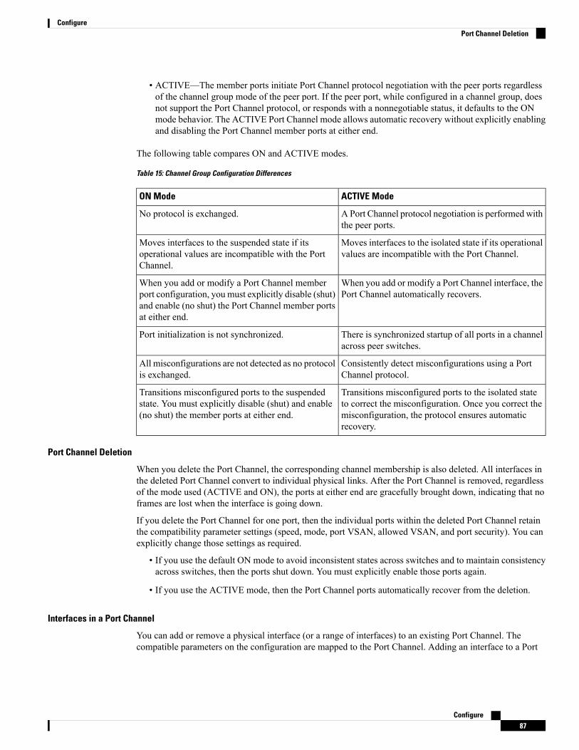
• ACTIVE—The member ports initiate Port Channel protocol negotiation with the peer ports regardlessof the channel group mode of the peer port. If the peer port, while configured in a channel group, doesnot support the Port Channel protocol, or responds with a nonnegotiable status, it defaults to the ONmode behavior. The ACTIVE Port Channel mode allows automatic recovery without explicitly enablingand disabling the Port Channel member ports at either end.
The following table compares ON and ACTIVE modes.
Table 15: Channel Group Configuration Differences
ACTIVE ModeON Mode
APort Channel protocol negotiation is performed withthe peer ports.
No protocol is exchanged.
Moves interfaces to the isolated state if its operationalvalues are incompatible with the Port Channel.
Moves interfaces to the suspended state if itsoperational values are incompatible with the PortChannel.
When you add or modify a Port Channel interface, thePort Channel automatically recovers.
When you add or modify a Port Channel memberport configuration, you must explicitly disable (shut)and enable (no shut) the Port Channel member portsat either end.
There is synchronized startup of all ports in a channelacross peer switches.
Port initialization is not synchronized.
Consistently detect misconfigurations using a PortChannel protocol.
All misconfigurations are not detected as no protocolis exchanged.
Transitions misconfigured ports to the isolated stateto correct the misconfiguration. Once you correct themisconfiguration, the protocol ensures automaticrecovery.
Transitions misconfigured ports to the suspendedstate. You must explicitly disable (shut) and enable(no shut) the member ports at either end.
Port Channel Deletion
When you delete the Port Channel, the corresponding channel membership is also deleted. All interfaces inthe deleted Port Channel convert to individual physical links. After the Port Channel is removed, regardlessof the mode used (ACTIVE and ON), the ports at either end are gracefully brought down, indicating that noframes are lost when the interface is going down.
If you delete the Port Channel for one port, then the individual ports within the deleted Port Channel retainthe compatibility parameter settings (speed, mode, port VSAN, allowed VSAN, and port security). You canexplicitly change those settings as required.
• If you use the default ON mode to avoid inconsistent states across switches and to maintain consistencyacross switches, then the ports shut down. You must explicitly enable those ports again.
• If you use the ACTIVE mode, then the Port Channel ports automatically recover from the deletion.
Interfaces in a Port Channel
You can add or remove a physical interface (or a range of interfaces) to an existing Port Channel. Thecompatible parameters on the configuration are mapped to the Port Channel. Adding an interface to a Port
Configure87
ConfigurePort Channel Deletion

Channel increases the channel size and bandwidth of the Port Channel. Removing an interface from a PortChannel decreases the channel size and bandwidth of the Port Channel.
This section describes interface configuration for a Port Channel and includes the following topics:
Interface Addition to a Port Channel
You can add a physical interface (or a range of interfaces) to an existing Port Channel. The compatibleparameters on the configuration are mapped to the Port Channel. Adding an interface to a Port Channelincreases the channel size and bandwidth of the Port Channel.
A port can be configured as a member of a static Port Channel only if the following configurations are thesame in the port and the Port Channel:
• Speed
• Mode
• Rate mode
• Port VSAN
• Trunking mode
• Allowed VSAN list or VF-ID list
After the members are added, regardless of the mode (ACTIVE and ON) used, the ports at either end aregracefully brought down, indicating that no frames are lost when the interface is going down (see the“Generation 1 Port Channel Limitations” section on page -12).
Compatibility Check
A compatibility check ensures that the same parameter settings are used in all physical ports in the channel.Otherwise, they cannot become part of a Port Channel. The compatibility check is performed before a port isadded to the Port Channel.
The check ensures that the following parameters and settings match at both ends of a Port Channel:
• Capability parameters (type of interface, Gigabit Ethernet at both ends, or Fibre Channel at both ends).
• Administrative compatibility parameters (speed, mode, rate mode, port VSAN, allowed VSAN list, andport security).
Ports in shared rate mode cannot form a Port Channel or a trunking Port Channel.Note
• Operational parameters (remote switch WWN and trunking mode).
A port addition procedure fails if the capability and administrative parameters in the remote switch areincompatible with the capability and administrative parameters in the local switch. If the compatibility checkis successful, the interfaces are operational and the corresponding compatibility parameter settings apply tothese interfaces.
Configure88
ConfigureInterfaces in a Port Channel

Suspended and Isolated States
If the operational parameters are incompatible, the compatibility check fails and the interface is placed in asuspended or isolated state based on the configured mode:
• An interface enters the suspended state if the interface is configured in the ON mode.
• An interface enters the isolated state if the interface is configured in the ACTIVE mode.
Forcing an Interface Addition
You can force the port configuration to be overwritten by the Port Channel. In this case, the interface is addedto a Port Channel.
• If you use the default ON mode to avoid inconsistent states across switches and to maintain consistencyacross switches, then the ports shut down. You have to explicitly enable those ports again.
• If you use the ACTIVE mode, then the Port Channel ports automatically recover from the addition.
When Port Channels are created from within an interface, the force option cannot be used.Note
After the members are forcefully added, regardless of the mode (ACTIVE and ON) used, the ports at eitherend are gracefully brought down, indicating that no frames are lost when the interface is going down.
Interface Deletion from a Port Channel
When a physical interface is deleted from the Port Channel, the channel membership is automatically updated.If the deleted interface is the last operational interface, then the Port Channel status is changed to a downstate. Deleting an interface from a Port Channel decreases the channel size and bandwidth of the Port Channel.
• If you use the default ON mode to avoid inconsistent states across switches and to maintain consistencyacross switches, then the ports shut down. You must explicitly enable those ports again.
• If you use the ACTIVE mode, then the Port Channel ports automatically recover from the deletion.
After the members are deleted, regardless of the mode (ACTIVE and ON) used, the ports at either end aregracefully brought down, indicating that no frames are lost when the interface is going down.
Port Channel Protocols
In earlier Cisco SAN-OS releases, Port Channels required additional administrative tasks to supportsynchronization. The Cisco NX-OS software provides robust error detection and synchronization capabilities.You can manually configure channel groups or they can be automatically created. In both cases, the channelgroups have the same capability and configurable parameters. Any change in configuration that is applied tothe associated Port Channel interface is propagated to all members of the channel group.
A protocol to exchange Port Channel configurations is available in all Cisco MDS switches. This additionsimplifies Port Channel management with incompatible ISLs. An additional autocreation mode enables ISLswith compatible parameters to automatically form channel groups without manual intervention.
The Port Channel protocol is enabled by default.
The Port Channel protocol expands the Port Channel functional model in Cisco MDS switches. It uses theexchange peer parameters (EPP) services to communicate across peer ports in an ISL. Each switch uses the
Configure89
ConfigurePort Channel Protocols

information that is received from the peer ports along with its local configuration and operational values todecide if it should be part of a Port Channel. The protocol ensures that a set of ports is eligible to be part ofthe same Port Channel. They are only eligible to be part of the same Port Channel if all the ports have acompatible partner.
The Port Channel protocol uses two subprotocols:
• Bringup protocol—Automatically detects misconfigurations so you can correct them. This protocolsynchronizes the Port Channel at both ends so that all frames for a given flow (as identified by the sourceFC ID, destination FC ID and OX_ID) are carried over the same physical link in both directions. Thishelps make applications such as write acceleration, work for Port Channels over FCIP links.
• Autocreation protocol—Automatically aggregates compatible ports into a Port Channel.
This section describes how to configure the Port Channel protocol and includes the following sections:
Channel Group Creation
Channel groups are not supported on internal ports in the Cisco Fabric Switch for HP c-Class BladeSystemand the Cisco Fabric Switch for IBM BladeSystem.
Note
Assuming link A1-B1 comes up first (see Figure 1-9), that link is operational as an individual link. When thenext link comes up, for example, A2-B2, the Port Channel protocol identifies if this link is compatible withlink A1-B1 and automatically creates channel groups 10 and 20 in the respective switches. If link A3-B3 canjoin the channel groups (the Port Channels), the respective ports have compatible configurations. If link A4-B4operates as an individual link, it is because of the incompatible configuration of the two end ports with theother member ports in this channel group.Figure 9: Autocreating Channel Groups – 120489.ps
The channel group numbers are selected dynamically, and as such, the administrative configuration of theports forming the channel group at either end are applicable to the newly created channel group. The channelgroup number being chosen dynamically may be different across reboots for the same set of Port Channelsbased on the order of ports that are initialized in the switch.
Table 1-10 identifies the differences between user-configured and auto-configured channel groups.
Autocreated Channel GroupUser-Configured Channel Group
Created automatically when compatible links come upbetween two compatible switches, if channel groupautocreation is enabled in all ports at both ends.
Manually configured by the user.
None of these ports are members of a user-configuredchannel group.
Member ports cannot participate in autocreationof channel groups. The autocreation featurecannot be configured.
All ports included in the channel group participate in thePort Channel—no member port becomes isolated orsuspended; instead, the member port is removed from thechannel group when the link is found to be incompatible.
You can form the Port Channel with a subset ofthe ports in the channel group. Incompatible portsremain in a suspended or isolated state dependingon the ON or ACTIVE mode configuration.
Configure90
ConfigurePort Channel Protocols
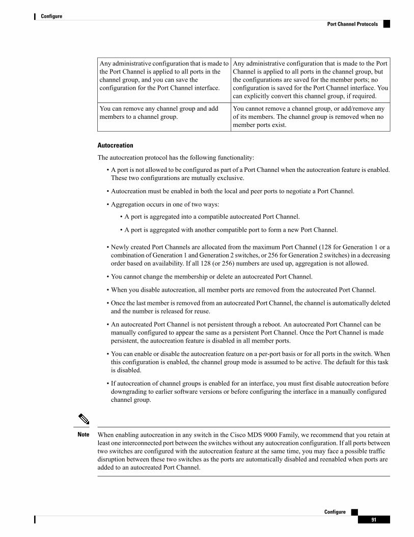
Any administrative configuration that is made to the PortChannel is applied to all ports in the channel group, butthe configurations are saved for the member ports; noconfiguration is saved for the Port Channel interface. Youcan explicitly convert this channel group, if required.
Any administrative configuration that is made tothe Port Channel is applied to all ports in thechannel group, and you can save theconfiguration for the Port Channel interface.
You cannot remove a channel group, or add/remove anyof its members. The channel group is removed when nomember ports exist.
You can remove any channel group and addmembers to a channel group.
Autocreation
The autocreation protocol has the following functionality:
• A port is not allowed to be configured as part of a Port Channel when the autocreation feature is enabled.These two configurations are mutually exclusive.
• Autocreation must be enabled in both the local and peer ports to negotiate a Port Channel.
• Aggregation occurs in one of two ways:
• A port is aggregated into a compatible autocreated Port Channel.
• A port is aggregated with another compatible port to form a new Port Channel.
• Newly created Port Channels are allocated from the maximum Port Channel (128 for Generation 1 or acombination of Generation 1 and Generation 2 switches, or 256 for Generation 2 switches) in a decreasingorder based on availability. If all 128 (or 256) numbers are used up, aggregation is not allowed.
• You cannot change the membership or delete an autocreated Port Channel.
• When you disable autocreation, all member ports are removed from the autocreated Port Channel.
• Once the last member is removed from an autocreated Port Channel, the channel is automatically deletedand the number is released for reuse.
• An autocreated Port Channel is not persistent through a reboot. An autocreated Port Channel can bemanually configured to appear the same as a persistent Port Channel. Once the Port Channel is madepersistent, the autocreation feature is disabled in all member ports.
• You can enable or disable the autocreation feature on a per-port basis or for all ports in the switch. Whenthis configuration is enabled, the channel group mode is assumed to be active. The default for this taskis disabled.
• If autocreation of channel groups is enabled for an interface, you must first disable autocreation beforedowngrading to earlier software versions or before configuring the interface in a manually configuredchannel group.
When enabling autocreation in any switch in the Cisco MDS 9000 Family, we recommend that you retain atleast one interconnected port between the switches without any autocreation configuration. If all ports betweentwo switches are configured with the autocreation feature at the same time, you may face a possible trafficdisruption between these two switches as the ports are automatically disabled and reenabled when ports areadded to an autocreated Port Channel.
Note
Configure91
ConfigurePort Channel Protocols

Manually Configured Channel Groups
A user-configured channel group cannot be converted to an autocreated channel group. However, you canconvert an autocreated channel group to a manual channel group. Once performed, this task is irreversible.The channel group number does not change, but the member ports operate according to the properties of themanually configured channel group, and the autocreation of channel group is implicitly disabled for all memberports.
If you enable persistence, be sure to enable it at both ends of the Port Channel.Tip
Prerequisites for Configuring Port ChannelsBefore configuring a Port Channel, consider the following guidelines:
• Configure the Port Channel across switching modules to implement redundancy on switching modulereboots or upgrades.
• Ensure that one Port Channel is not connected to different sets of switches. Port Channels requirepoint-to-point connections between the same set of switches.
On switches with Generation 1 switching modules, or a combination of Generation 1 and Generation 2switching modules, you can configure a maximum of 128 Port Channels. On switches with only Generation2 switching modules, or Generation 2 and Generation 3 switching modules, you can configure a maximumof 256 Port Channels.
If you misconfigure Port Channels, you may receive a misconfiguration message. If you receive this message,the Port Channel’s physical links are disabled because an error has been detected.
A Port Channel error is detected if the following requirements are not met:
• Each switch on either side of a Port Channel must be connected to the same number of interfaces.
• Each interface must be connected to a corresponding interface on the other side (see Figure 1-11 for anexample of an invalid configuration).
• Links in a Port Channel cannot be changed after the Port Channel is configured. If you change the linksafter the Port Channel is configured, be sure to reconnect the links to interfaces within the Port Channeland reenable the links.
If all three conditions are not met, the faulty link is disabled.
Enter the show interface command for that interface to verify that the Port Channel is functioning as required.
Guidelines and Limitations for Configuring Port ChannelsThis section includes the guidelines and limitations for this feature:
General Guidelines for Cisco MDS 9000 Series Switches
Cisco MDS 9000 Family switches support the following number of Port Channels per switch:
• Switches with only Generation 1 switching modules do not support F and TF Port Channels.
Configure92
ConfigurePrerequisites for Configuring Port Channels

• Switches with Generation 1 switching modules, or a combination of Generation 1 and Generation 2switching modules, support a maximum of 128 Port Channels. Only Generation 2 ports can be includedin the Port Channels.
• Switches with only Generation 2 switching modules or Generation 2 and Generation 3 modules supporta maximum of 256 Port Channels with 16 interfaces per Port Channel.
• A Port Channel number refers to the unique identifier for each channel group. This number ranges fromof 1 to 256.
Generation 1 Port Channel Limitations
This section includes the restrictions on creation and addition of Port Channel members to a Port Channel onGeneration 1 hardware:
• The 32-port 2-Gbps or 1-Gbps switching module.
• The MDS 9140 and 9120 switches.
When configuring the host-optimized ports on Generation 1 hardware, the following Port Channel guidelinesapply:
• If you execute the write erase command on a 32-port switching module, and then copy a savedconfiguration to the switch from a text file that contains the no system default switchport shutdowncommand, you have to copy the text file to the switch again for the E ports to come up without manualconfiguration.
• Any (or all) full line rate ports in the Cisco MDS 9100 Series can be included in a Port Channel.
• The host-optimized ports in the Cisco MDS 9100 Series are subject to the same Port Channel rules as32-port switching modules; only the first port of each group of four ports is included in a Port Channel.
• You can configure only the first port in each 4-port group as an E port (for example, the first portin ports 1–4, the fifth port in ports 5–8, and so on). If the first port in the group is configured as aPort Channel, the other three ports in each group (ports 2–4, 6–8, and so on) are not usable andremain in the shutdown state.
• If any of the other three ports are configured in a no shutdown state, you cannot configure the firstport to be a Port Channel. The other three ports continue to remain in a no shutdown state.
F and TF Port Channel Limitations
The following guidelines and restrictions are applicable for F and TF Port Channels:
• The ports must be in F mode.
• Automatic creation is not supported.
• The Port Channel interface must be in ACTIVE mode when multiple FCIP interfaces are grouped withWA.
• ONmode is not supported. Only ACTIVE-ACTIVEmode is supported. By default, the mode is ACTIVEon the NPV switches.
• Devices that are logged in through F Port Channel on anMDS switch are not supported in IVR non-NATconfiguration. The devices are supported only in IVR NAT configuration.
Configure93
ConfigureGuidelines and Limitations for Configuring Port Channels

• Port security rules are enforced only on physical pWWNs at the single link level.
• FC-SP authenticates only the first physical FLOGI of every Port Channel member.
• Since the FLOGI payload carries only the VF bits to trigger the use of a protocol after the FLOGIexchange, those bits will be overridden. In the case of the NPV switches, the core has a Cisco WWNand tries to initiate the PCP protocol.
• The name server registration of the N ports logging in through an F Port Channel uses the fWWN of thePort Channel interface.
• DPVM configuration is not supported.
• The Port Channel port VSAN cannot be configured using DPVM.
• The Dynamic Port VSAN Management (DPVM) database is queried only for the first physical FLOGIof each member, so that the port VSAN can be configured automatically.
• DPVM does not bind FC_IDs to VSANs, but pWWNs to VSANs. It is queried only for the physicalFLOGI.
Valid and Invalid Port Channel Examples
Port Channels are created with default values. You can change the default configuration just like any otherphysical interface. The following figure provides examples of valid Port Channel configurations.Figure 10: Valid Port Channel Configurations – 120480.ps
The following figure provides examples of invalid configurations. Assuming that the links are brought up inthe 1, 2, 3, 4 sequence, links 3 and 4 will be operationally down as the fabric is misconfigured.Figure 11: Misconfigured Configurations – 120488.ps
Default SettingsThe following table lists the default settings for Port Channels.
Table 16: Default Port Channel Parameters
DefaultParameters
FSPF is enabled by default.Port Channels
Administratively up.Create Port Channel
ONmode on non-NPV andNPIV core switches.
ACTIVE mode on NPV switches.
Default Port Channelmode
Disabled.Autocreation
Create Port Channel WizardTo create a Port Channel using the Create New Port Channel Wizard on the DCNMWeb UI, perform thefollowing steps:
Configure94
ConfigureValid and Invalid Port Channel Examples

Procedure
Step 1 Choose Configure > SAN > Port Channel.
Click Create New Port Channel to launch the Create Port Channel Wizard.
Step 2 In the Select Switch Pair screen, perform the following steps:a) Select the appropriate fabric from the Fabric drop-down.
The list contains switch pairs in the fabric that have an ISL between them, that is not already in a portchannel.
b) Select a switch pair to be linked by an FC Port Channel.
If there are NPV links between NPIV-core and NPV switches, you must enable F Port Trunking andChanneling Protocol using the feature fport-channel-trunk command on the NPIV switch in order tosee the switch-pair and the number of NPV links.
c) Click Next.
Step 3 In the Select ISLs screen, select one or more ISLs or Links to create a new Channel between the switch pair.a) From the list of ISLs in the Available area, select and click right arrow to move the ISL to the Selected
area.b) Click Next.
Step 4 In the Create Port Channel screen, define, or edit the channel attributes.a) Channel ID field is populated with the next unused channel ID. Change the channel ID or description for
each switch, if necessary.
The range of the channel ID is from 1 to 256.
b) FICON Port Address is only enabled if the switches are FICON enabled. From the drop-down list, selectthe appropriate FICON port address on the switch. Select the port address that you want to assign to thePort Channel port.
c) In the Channel Attributes area, to configure the speed, click the appropriate radio button.d) Select the appropriate Trunk Mode radio button to enable trunking on the links in the Port Channel.
• Select trunk if your link is between TE ports.
• Select nonTrunk if your link is between E ports.
• Select auto if you are not sure.
e) In the Port VSAN field, enter the interface ID for port VSAN which must be used when trunking is notenabled.
Every interface must have a port VSAN even if trunking is enabled. If trunking is enabled, this port VSANis not used. However, the switch must configure the port, so that the network knows what VSAN to useby default, if trunking is disabled.
f) VSAN list field provides a list of VSANs you want to allow the port channel to use for trunking.
This field is disabled if the Trunk Mode is set to nonTrunk or auto.
g) In the Core Switch Bandwidth field, select dedicated or shared radio button to allocate the switch bandwidth.
This bandwidth is applicable only for port channels between an NPIV and NPV switch.
Configure95
ConfigureCreate Port Channel Wizard

h) Check the Force Admin, Trunk, Speed, and VSAN attributes to be identical checkbox to ensure thatthe same parameter settings are used in all physical ports in the channel. If these settings are not identical,the ports cannot become part of the Port Channel.
Step 5 Click Previous to return to the previous screen and edit the settings. Click Finish to configure the Port Channel.
A success message appears.
Step 6 Click Close to close the Create Port Channel Wizard.
Edit Existing Port ChannelTo edit a Port Channel using the Edit Port Channel Wizard on the DCNMWeb UI, perform the followingsteps:
Procedure
Step 1 Choose Configure > SAN > Port Channel.
The Port Channel window is displayed.
Click Edit Existing Port Channel to launch the Edit Port Channel Wizard.
Step 2 In the Select Switch Pair screen, perform the following steps:a) Select the appropriate fabric from the Fabric drop-down list.
The switch pairs that have port channels between them is displayed.
b) Select a switch pair to edit the port channel.c) Click Next.
Step 3 In the Select Port Channel screen, select a Port Channel to edit.
Click Next.
Step 4 In the Edit Port Channel screen, select the desired ISL.a) Click the right and left arrow to select the available ISLs.
The selected ISLs are contained in the Port Channel after you save the changes. If the SelectedISLs list is empty, the Delete Port Channel is Empty checkbox is enabled.
Note
b) If you do not choose any ISL, check the Delete Port Channel if Empty checkbox to delete the portchannel.
c) Check the Force admin, trunk, speed, VSAN attributes to be identical checkbox to choose identicalvalues for admin, trunk, speed, and VSAN attributes.
d) Click Next.
Step 5 Click Finish to apply the changes.
Click Previous to go back to the previous screen and edit the values.
Click Cancel to discard the changes.
Configure96
ConfigureEdit Existing Port Channel

Device AliasA device alias is a user-friendly name for a port WWN. Device alias name can be specified when configuringfeatures such as zoning, QoS, and port security. The device alias application uses the Cisco Fabric Services(CFS) infrastructure to enable efficient database management and fabric-wide distribution.
This section contains context-sensitive online help content under Configure > SAN > Device Alias.
The following table describes the fields that appear under Configure > SAN > Device Alias.
DescriptionField
Displays the device alias seed switch name.Seed Switch
Displays the alias retrieved from the seed switch.Device Alias
Displays the port WWN.pWWN
This section contains the following:
ConfigurationSelect the Fabric from the Fabric drop-down list. The list of device aliases existing on the fabric will beretrieved and displayed.
Before performing any Device Alias configuration, check the status on the CFS tab, to ensure that the statusis "success".
To perform Device Alias configuration from the Cisco DCNMWeb client, the fabric must be configured asDevice Alias enhanced mode.
Note
Procedure
Step 1 To delete the device alias, Cisco DCNMWeb Client > Configure > SAN > Device Alias > Configurationtab, check the device alias you need to delete.a) Click Delete.
A confirmation message appears.
Deleting the device alias may cause traffic interruption.Note
b) Click Yes to delete the topic alias.
Step 2 To create the device alias, from Cisco DCNMWeb Client > Configure > SAN > Device Alias >Configuration tab, click Create.
The Add Device Alias windows appears.
All the provisioned port WWNs are populated in the table.
a) Enter a device alias name in the Device Alias field to indicate to create a device alias for the selectedpWWN.
Configure97
ConfigureDevice Alias

b) Click Save to exit the inline editor mode.c) Click Apply to assign the device alias to the switches.
You can also create a device alias with a non-provisioned port WWN.
a) Click New Alias to create a new table row in inline editor mode.b) In the pWWN field, enter the non-provisioned port WWN for the new alias.c) Click Save to exit the inline editor mode.d) Click Apply to assign the device alias and the associated pWWN to the switches.
If you close the Add Device Alias window before applying the device alias to the switches, thechanges will be discarded and the device alias will not be created.
Note
Step 3 For end devices with an attached service profile, the service profile name is populated to the Device Aliasfield. This allows the service profile name as device alias name for those devices.
Device Alias creation is CFS auto-committed after clicking Apply. ClickCFS tab to check if CFS is properlyperformed after the device alias was created. In case of failure, you must troubleshoot and fix the problem.
CFSSelect the Fabric from the Fabric drop-down list. The list of device aliases existing on the fabric is retrievedand displayed.
CFS information is listed for all the eligible switches in the fabric. Before performing any Device Aliasconfiguration, check the status on the CFS tab to ensure that the status is "success". If the CFS is locked byanother user, or if the previous operation failed, ensure that the CFS session is unlocked.
To view CFS information from the Cisco DCNMWeb UI, perform the following steps:
Procedure
Step 1 Choose Configure > SAN > Device Alias > CFS.Step 2 To commit the CFS configuration, select the Switch radio button.
Click Commit.
The CFS configuration for this switch is committed.
Step 3 To abort the CFS configuration, select the Switch radio button.
Click Abort.
The CFS configuration for this switch is aborted.
Step 4 To clear the lock on the CFS configuration of the switch, select the Switch radio button.
Click Clear Lock.
If the CFS is locked by another user, or if the previous operation failed, ensure that the CFS session is unlocked.
Configure98
ConfigureCFS

Port MonitoringThis feature allows you to save custom Port Monitoring policies in the Cisco DCNM database. It allows youto push the selected custom policy to one or more fabrics or Cisco MDS 9000 Series Switches. The policy isdesignated as active Port-Monitor policy in the switch.
This feature is supported only on the Cisco MDS 9000 SAN Switches and therefore the Cisco DCNM useris allowed to select the MDS switch to push the policy.
Cisco DCNMprovides five templates to customize the policy. The user-defined policies are saved in the CiscoDCNM database. You can select any template or customized policy to push to the selected fabric or switchwith the desired port type.
You can edit only user-defined policies.Note
The following table describes the fields that appear on Cisco DCNM Configure > SAN > Port Monitoring.
DescriptionField
This drop-down list shows the following templatesfor policies:
Templates
• Normal_accessPort
• Normal_allPort
• Normal_trunksPort
• Aggressive_accessPort
• Aggressive_allPort
• Aggressive_trunksPort
• Most-Aggressive_accessPort
• Most-Aggressive_allPort
• Most-Aggressive_trunksPort
• default
• slowdrain
Allows you to save your changes for the user-definedpolicies.
Save
Allows you to save an existing policy as a new policywith a different name.
Save As
This creates another item in the templates as CustomPolicy. The customized policy is saved under thiscategory.
If you click Save As while the policy is edited, thecustomized policy is saved.
Configure99
ConfigurePort Monitoring
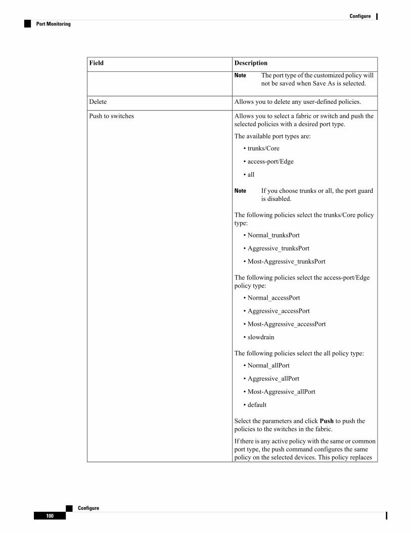
DescriptionField
The port type of the customized policy willnot be saved when Save As is selected.
Note
Allows you to delete any user-defined policies.Delete
Allows you to select a fabric or switch and push theselected policies with a desired port type.
Push to switches
The available port types are:
• trunks/Core
• access-port/Edge
• all
If you choose trunks or all, the port guardis disabled.
Note
The following policies select the trunks/Core policytype:
• Normal_trunksPort
• Aggressive_trunksPort
• Most-Aggressive_trunksPort
The following policies select the access-port/Edgepolicy type:
• Normal_accessPort
• Aggressive_accessPort
• Most-Aggressive_accessPort
• slowdrain
The following policies select the all policy type:
• Normal_allPort
• Aggressive_allPort
• Most-Aggressive_allPort
• default
Select the parameters and click Push to push thepolicies to the switches in the fabric.
If there is any active policy with the same or commonport type, the push command configures the samepolicy on the selected devices. This policy replaces
Configure100
ConfigurePort Monitoring

DescriptionField
the existing active policy with the same or commonport type.
If you click Push to Switches while the policy isedited, the customized policy will not be saved.
Specifies the counter type.Counter Description
Move the pointer to the "i" icon next to the counterdescription to view detailed information.
Specifies the upper threshold limit for the countertype.
Rising Threshold
Specifies the type of event to be generated when risingthreshold is reached or crossed.
Rising Event
Specifies the lower threshold limit for the countertype.
Falling Threshold
Specifies the type of event to be generated whenfalling threshold is reached or crossed.
Falling Event
Specifies the time interval to poll for the countervalue.
Poll Interval
Allows you to set an optional threshold value lowerthan the rising threshold value and higher than the
Warning Threshold
falling threshold value to generate syslogs. The rangeis 0–9223372036854775807.
Specifies if the port guard is enabled or disabled. Thevalue can be false, flap, or errordisable.
Port Guard
The default value is "false".
The default value is "true".Monitor ?
Configuring SAN InsightsTo configure SAN insights from the Cisco DCNMWeb UI, perform the following steps:
Procedure
Step 1 Choose Configure > SAN > SAN Insights. The Configure SAN Insights wizard appears.
Configure101
ConfigureConfiguring SAN Insights

Step 2 In the Configure SAN Insights page, click Continue.
Step 3 Select a fabric where you want the SAN Insights functionality to be configured. The wizard works with onefabric at a time.
Configure102
ConfigureConfiguring SAN Insights
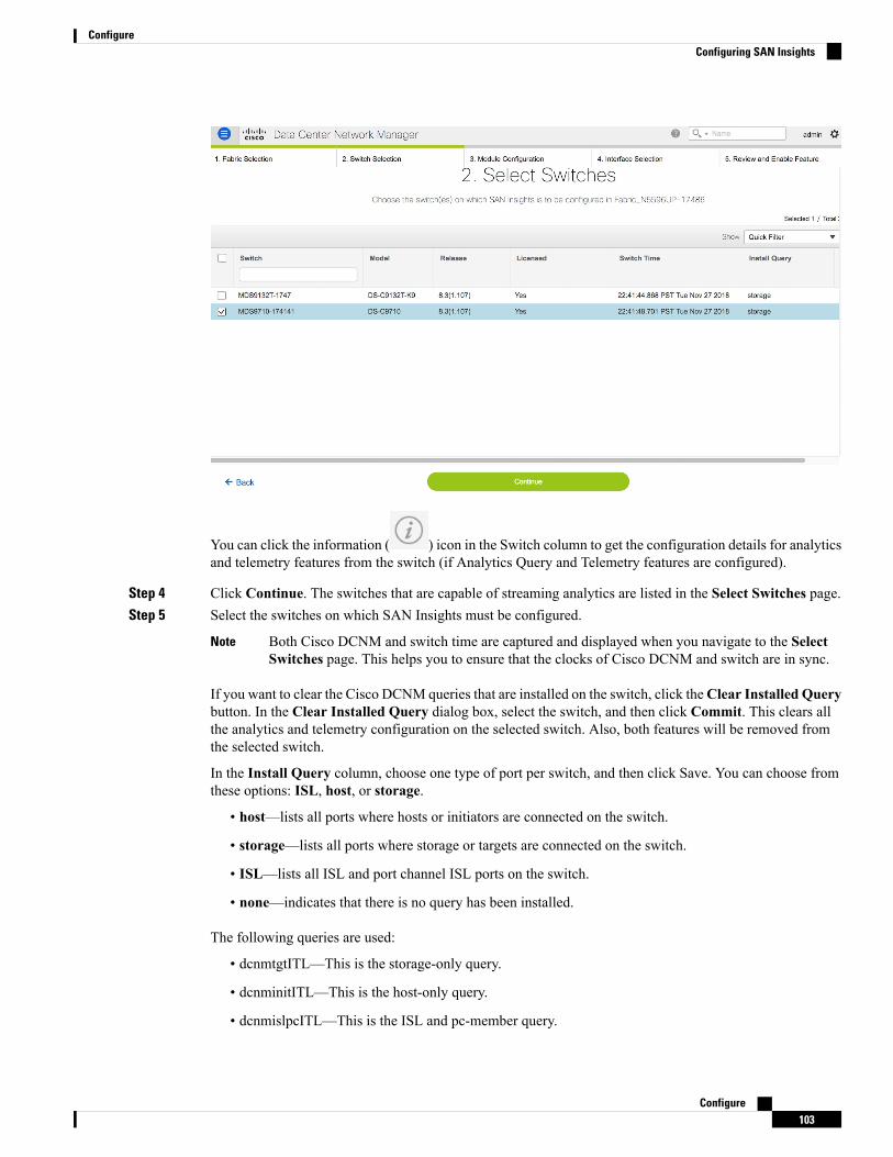
You can click the information ( ) icon in the Switch column to get the configuration details for analyticsand telemetry features from the switch (if Analytics Query and Telemetry features are configured).
Step 4 Click Continue. The switches that are capable of streaming analytics are listed in the Select Switches page.Step 5 Select the switches on which SAN Insights must be configured.
Both Cisco DCNM and switch time are captured and displayed when you navigate to the SelectSwitches page. This helps you to ensure that the clocks of Cisco DCNM and switch are in sync.
Note
If you want to clear the Cisco DCNM queries that are installed on the switch, click theClear Installed Querybutton. In the Clear Installed Query dialog box, select the switch, and then click Commit. This clears allthe analytics and telemetry configuration on the selected switch. Also, both features will be removed fromthe selected switch.
In the Install Query column, choose one type of port per switch, and then click Save. You can choose fromthese options: ISL, host, or storage.
• host—lists all ports where hosts or initiators are connected on the switch.
• storage—lists all ports where storage or targets are connected on the switch.
• ISL—lists all ISL and port channel ISL ports on the switch.
• none—indicates that there is no query has been installed.
The following queries are used:
• dcnmtgtITL—This is the storage-only query.
• dcnminitITL—This is the host-only query.
• dcnmislpcITL—This is the ISL and pc-member query.
Configure103
ConfigureConfiguring SAN Insights

When the administrator selects the ISL/Host/Storage on the configure wizard, the respective ports are filteredand listed on the next step.
Step 6 Click Continue. You can see all the analytics supported modules on the switches selected in the previousview, listed with the respective instantaneous NPU load in the last column. Port-sampling configuration(optional) for the module can be specified in this step. The default configuration on the switch is to monitorall analytics-enabled ports on the switch for analytics.
Step 7 In the Configure Modules tab, configure the module(s) for SAN Insights functionality.
To change the values for Sample Window (ports) and Rotation Interval (seconds), click the row and enterthe desired values.
• To undo the changes, click Cancel.
• To save changes, click Save.
The NPU Load column displays the network processing unit (NPU) within a module.
Step 8 Click Continue.
Configure104
ConfigureConfiguring SAN Insights

Step 9 In the Select Interfaces tab, select the interfaces that generate analytics data within the fabric.You can click the toggle button to enable or disable analytics on the desired port.
Step 10 Click Continue, and then review the changes that you have made.
Step 11 Click Commit. The CLI is executed on the switch.Step 12 Review the results and see that the response is successful.Step 13 Click Close to return to the home page. The Close button appears only after all CLI commands are executed
on the switch.
Configure105
ConfigureConfiguring SAN Insights

If you want to make any changes to the SAN Insights configurations, you can navigate to the SAN Insightspage and make necessary configuration changes.
Increasing Elasticsearch Database Heap Size
Procedure
Step 1 To specify the Elasticsearch Heap Size on Windows PowerShell, perform the following steps:a) Access Windows Desktop UI as Administrator and open Powershellb) Stop elastic search and open elastic search manager using the below CLI commandsc) Navigate to Java Tab and Update: -Xms6g and -Xmx6g in the Java Optionsd) Change the Initial and Maximum memory pool to 6144 and click apply and OK to close the windowe) Start elastic search service using the below commands.
Configure106
ConfigureIncreasing Elasticsearch Database Heap Size

The example below shows the Windows CLI Commands:PS C:\Users\Administrator> & 'C:\Program Files\CiscoSystems\dcm\elasticsearch\bin\elasticsearch-service.bat' stop
PS C:\Users\Administrator> & 'C:\Program Files\CiscoSystems\dcm\elasticsearch\bin\elasticsearch-service.bat' manager
PS C:\Users\Administrator> & 'C:\Program Files\CiscoSystems\dcm\elasticsearch\bin\elasticsearch-service.bat' start
Step 2 To specify the Elasticsearch Heap Size on Linux CLI, perform the following steps:a) service elasticsearch stopb) vi <install-folder>/dcm/elasticsearch/config/jvm.optionsc) Update: -Xms6g and -Xmx6g and save and close the filed) service elasticsearch start
Scripts are located at the relative folder location where DCNM is installedNote
Configure107
ConfigureIncreasing Elasticsearch Database Heap Size

Configure108
ConfigureIncreasing Elasticsearch Database Heap Size