Embed Size (px)
Citation preview

Configuration — Link Aggregation, MLT,and SMLTAvaya Ethernet Routing Switch 8300
4.2NN46200-517, 02.05
August 2011
© 2011 Avaya Inc.
All Rights Reserved.
Notice
While reasonable efforts have been made to ensure that theinformation in this document is complete and accurate at the time ofprinting, Avaya assumes no liability for any errors. Avaya reserves theright to make changes and corrections to the information in thisdocument without the obligation to notify any person or organization ofsuch changes.
Documentation disclaimer
Avaya shall not be responsible for any modifications, additions, ordeletions to the original published version of this documentation unlesssuch modifications, additions, or deletions were performed by Avaya.End User agree to indemnify and hold harmless Avaya, Avaya's agents,servants and employees against all claims, lawsuits, demands andjudgments arising out of, or in connection with, subsequentmodifications, additions or deletions to this documentation, to theextent made by End User.
Link disclaimer
Avaya is not responsible for the contents or reliability of any linked Websites referenced within this site or documentation(s) provided by Avaya.Avaya is not responsible for the accuracy of any information, statementor content provided on these sites and does not necessarily endorsethe products, services, or information described or offered within them.Avaya does not guarantee that these links will work all the time and hasno control over the availability of the linked pages.
Warranty
Avaya provides a limited warranty on this product. Refer to your salesagreement to establish the terms of the limited warranty. In addition,Avaya’s standard warranty language, as well as information regardingsupport for this product, while under warranty, is available to Avayacustomers and other parties through the Avaya Support Web site: http://www.avaya.com/support. Please note that if you acquired theproduct from an authorized Avaya reseller outside of the United Statesand Canada, the warranty is provided to you by said Avaya reseller andnot by Avaya.
Licenses
THE SOFTWARE LICENSE TERMS AVAILABLE ON THE AVAYAWEBSITE, HTTP://SUPPORT.AVAYA.COM/LICENSEINFO/ AREAPPLICABLE TO ANYONE WHO DOWNLOADS, USES AND/ORINSTALLS AVAYA SOFTWARE, PURCHASED FROM AVAYA INC.,ANY AVAYA AFFILIATE, OR AN AUTHORIZED AVAYA RESELLER(AS APPLICABLE) UNDER A COMMERCIAL AGREEMENT WITHAVAYA OR AN AUTHORIZED AVAYA RESELLER. UNLESSOTHERWISE AGREED TO BY AVAYA IN WRITING, AVAYA DOESNOT EXTEND THIS LICENSE IF THE SOFTWARE WAS OBTAINEDFROM ANYONE OTHER THAN AVAYA, AN AVAYA AFFILIATE OR ANAVAYA AUTHORIZED RESELLER, AND AVAYA RESERVES THERIGHT TO TAKE LEGAL ACTION AGAINST YOU AND ANYONEELSE USING OR SELLING THE SOFTWARE WITHOUT A LICENSE.BY INSTALLING, DOWNLOADING OR USING THE SOFTWARE, ORAUTHORIZING OTHERS TO DO SO, YOU, ON BEHALF OFYOURSELF AND THE ENTITY FOR WHOM YOU ARE INSTALLING,DOWNLOADING OR USING THE SOFTWARE (HEREINAFTERREFERRED TO INTERCHANGEABLY AS “YOU” AND “END USER”),AGREE TO THESE TERMS AND CONDITIONS AND CREATE ABINDING CONTRACT BETWEEN YOU AND AVAYA INC. OR THEAPPLICABLE AVAYA AFFILIATE ( “AVAYA”).
Copyright
Except where expressly stated otherwise, no use should be made ofmaterials on this site, the Documentation(s) and Product(s) providedby Avaya. All content on this site, the documentation(s) and theproduct(s) provided by Avaya including the selection, arrangement anddesign of the content is owned either by Avaya or its licensors and is
protected by copyright and other intellectual property laws including thesui generis rights relating to the protection of databases. You may notmodify, copy, reproduce, republish, upload, post, transmit or distributein any way any content, in whole or in part, including any code andsoftware. Unauthorized reproduction, transmission, dissemination,storage, and or use without the express written consent of Avaya canbe a criminal, as well as a civil, offense under the applicable law.
Third-party components
Certain software programs or portions thereof included in the Productmay contain software distributed under third party agreements (“ThirdParty Components”), which may contain terms that expand or limitrights to use certain portions of the Product (“Third Party Terms”).Information regarding distributed Linux OS source code (for thoseProducts that have distributed the Linux OS source code), andidentifying the copyright holders of the Third Party Components and theThird Party Terms that apply to them is available on the Avaya SupportWeb site: http://www.avaya.com/support/Copyright/.
Trademarks
The trademarks, logos and service marks (“Marks”) displayed in thissite, the documentation(s) and product(s) provided by Avaya are theregistered or unregistered Marks of Avaya, its affiliates, or other thirdparties. Users are not permitted to use such Marks without prior writtenconsent from Avaya or such third party which may own the Mark.Nothing contained in this site, the documentation(s) and product(s)should be construed as granting, by implication, estoppel, or otherwise,any license or right in and to the Marks without the express writtenpermission of Avaya or the applicable third party.
Avaya is a registered trademark of Avaya Inc.
All other trademarks are the property of their respective owners.
Downloading documents
For the most current versions of documentation, see the Avaya SupportWeb site: http://www.avaya.com/support
Contact Avaya Support
Avaya provides a telephone number for you to use to report problemsor to ask questions about your product. The support telephone numberis 1-800-242-2121 in the United States. For additional supporttelephone numbers, see the Avaya Web site: http://www.avaya.com/support
2 Configuration — Link Aggregation, MLT, and SMLT August 2011Comments? [email protected]
Contents
Chapter 1: New in this release........................................................................................... 7Features.................................................................................................................................................... 7Other changes........................................................................................................................................... 7
Customer service............................................................................................................................. 7Chapter 2: Introduction...................................................................................................... 9Chapter 3: Link aggregation fundamentals...................................................................... 11
Link aggregation overview........................................................................................................................ 11MultiLink trunking...................................................................................................................................... 12
MultiLink trunking navigation............................................................................................................ 12MLT traffic distribution...................................................................................................................... 13MLT and MLT with LACP configuration rules................................................................................... 14LAG rules......................................................................................................................................... 15MLT network topology and configuration examples......................................................................... 15
MultiLink Trunking with LACP................................................................................................................... 18IEEE 802.3ad overview.................................................................................................................... 19802.3ad link aggregation principles.................................................................................................. 20
Split MultiLink Trunking............................................................................................................................. 22Split MultiLink Trunking navigation................................................................................................... 22SMLT overview................................................................................................................................. 22SMLT versus STP............................................................................................................................. 23SMLT topologies............................................................................................................................... 24SMLT and Interswitch trunking......................................................................................................... 24SMLT and IST traffic flow example................................................................................................... 27Single port SMLT.............................................................................................................................. 28MLT-based SMLT with single port SMLT.......................................................................................... 30SMLT and LACP support.................................................................................................................. 31SMLT and IP routing......................................................................................................................... 32SMLT and SLPP............................................................................................................................... 34SMLT network design considerations............................................................................................... 34
Virtual Link Aggregation Control Protocol................................................................................................. 34Link aggregation configuration considerations.......................................................................................... 37
Link aggregation configuration considerations navigation................................................................ 37MLT with LACP configuration considerations................................................................................... 37MLT with LACP and SMLT configuration considerations.................................................................. 38MLT with LACP and Spanning Tree configuration considerations................................................... 39LACP parameters configuration considerations............................................................................... 40
Chapter 4: Link aggregation configuration using Device Manager............................... 43LACP configuration using Device Manager.............................................................................................. 43
LACP configuration using Device Manager navigation.................................................................... 44Configuring LACP globally using Device Manager........................................................................... 44Configuring LACP on a port using Device Manager......................................................................... 46Viewing LACP parameters using Device Manager........................................................................... 51
MLT and SMLT link aggregation configuration using Device Manager..................................................... 52MLT and SMLT configuration using Device Manager navigation..................................................... 52
Configuration — Link Aggregation, MLT, and SMLT August 2011 3
Configuring a MultiLink trunk using Device Manager....................................................................... 53Adding ports to an MLT using Device Manager................................................................................ 56Deleting ports from an MLT using Device Manager......................................................................... 57Configuring MLT-based SMLT using Device Manager..................................................................... 58Deleting MLT-based SMLT using Device Manager.......................................................................... 59Viewing MLT-based SMLT information using Device Manager........................................................ 59Configuring a single-port SMLT using Device Manager................................................................... 60Deleting a single-port SMLT using Device Manager........................................................................ 61Viewing single-port SMLT information using Device Manager......................................................... 62Configuring rate limiting using Device Manager............................................................................... 62Configuring an IST MLT using Device Manager............................................................................... 63Removing an IST MLT using Device Manager................................................................................. 64
VLACP configuration using Device Manager............................................................................................ 65VLACP configuration using Device Manager navigation.................................................................. 65Configuring VLACP globally using Device Manager........................................................................ 65Configuring port-based VLACP using Device Manager................................................................... 66
Chapter 5: Link aggregation configuration using the CLI............................................... 69LACP configuration using the CLI............................................................................................................. 69
LACP configuration using the CLI navigation................................................................................... 70Job aid: Roadmap of LACP CLI commands..................................................................................... 70Configuring LACP globally using the CLI......................................................................................... 72Viewing global LACP configuration information using the CLI......................................................... 73Configuring port-based LACP using the CLI.................................................................................... 74Viewing port-based LACP configuration information using the CLI.................................................. 76
MLT and SMLT link aggregation configuration using the CLI.................................................................... 77MLT and SMLT configuration navigation.......................................................................................... 78Job aid: Roadmap of MLT, SMLT, and IST CLI commands.............................................................. 78Configuring a MultiLink trunk using the CLI...................................................................................... 79Viewing all MLT information using the CLI....................................................................................... 81Configuring a single-port SMLT using the CLI.................................................................................. 82Viewing single-port SMLT information using the CLI........................................................................ 82
Viewing SMLT information using the CLI.................................................................................................. 83Configuring rate limiting using the CLI...................................................................................................... 83Configuring an MLT-based SMLT using the CLI....................................................................................... 84Configuring LACP on an MLT using the CLI............................................................................................. 84Viewing MLT LACP information using the CLI.......................................................................................... 86Configuring an IST MLT using the CLI...................................................................................................... 86Viewing the IST configuration information using the CLI.......................................................................... 87Viewing MLT Ethernet error information using the CLI............................................................................. 88Viewing MLT collision error information using the CLI.............................................................................. 90VLACP configuration using the CLI.......................................................................................................... 91
VLACP configuration using the CLI navigation................................................................................ 91Job aid: Roadmap of VLACP commands......................................................................................... 91Configuring VLACP globally using the CLI....................................................................................... 92
Viewing global VLACP configuration information using the CLI................................................................ 93Configuring port-based VLACP using the CLI.......................................................................................... 93Viewing port-based VLACP configuration information using the CLI........................................................ 95
4 Configuration — Link Aggregation, MLT, and SMLT August 2011
Chapter 6: Link aggregation configuration using the ACLI............................................ 97LACP configuration using the ACLI.......................................................................................................... 97
LACP configuration using the ACLI navigation................................................................................ 98Configuring LACP globally using the ACLI....................................................................................... 100Disabling LACP globally using the ACLI.......................................................................................... 101Configuring LACP on a port using the ACLI..................................................................................... 102Disabling LACP on a port using the ACLI........................................................................................ 104Viewing LACP configuration information using the ACLI.................................................................. 105Viewing LACP interface configuration information using the ACLI................................................... 107
MLT and SMLT link aggregation configuration using the ACLI................................................................. 108MLT and SMLT configuration navigation.......................................................................................... 108Job aid: Roadmap of MLT, SMLT, and IST ACLI commands............................................................ 109Creating an MLT using the ACLI...................................................................................................... 110Configuring a MultiLink trunk using the ACLI................................................................................... 111Deleting an MLT using the ACLI....................................................................................................... 112Removing MLT encapsulation using the ACLI.................................................................................. 113Deleting port members from an MLT using the ACLI....................................................................... 113Removing an MLT name using the ACLI.......................................................................................... 114Disabling ASTG using the ACLI ....................................................................................................... 114Configuring LACP on an MLT using the ACLI.................................................................................. 115Disabling LACP on an MLT using the ACLI...................................................................................... 116Viewing MLT information using the ACLI.......................................................................................... 116Creating a single-port SMLT using the ACLI.................................................................................... 117Deleting a single-port SMLT using the ACLI..................................................................................... 118Configuring rate limiting using the ACLI........................................................................................... 118Creating an MLT-based SMLT using the ACLI................................................................................. 119Deleting an SMLT from an MLT using the ACLI............................................................................... 119Viewing the SMLT configuration using the ACLI.............................................................................. 120Configuring an IST MLT using the ACLI........................................................................................... 121Disabling an IST using the ACLI...................................................................................................... 121Clearing an InterSwitch trunk configuration using the ACLI............................................................. 122Viewing the IST configuration using the ACLI.................................................................................. 122Viewing MLT Ethernet error information using the ACLI.................................................................. 123Viewing MLT collision error information using the ACLI................................................................... 125
VLACP configuration using the ACLI........................................................................................................ 127VLACP configuration using the ACLI navigation.............................................................................. 127Job aid: Roadmap of VLACP ACLI commands................................................................................ 127Configuring VLACP globally using the ACLI.................................................................................... 128Viewing the global VLACP configuration using the ACLI................................................................. 128Configuring port-based VLACP using the ACLI............................................................................... 129Disabling port-based VLACP using the ACLI................................................................................... 130Viewing the port-based VLACP configuration using the ACLI.......................................................... 130
Chapter 7: MLT with LACP CLI configuration example................................................... 133Chapter 8: SMLT CLI configuration examples.................................................................. 135
SMLT triangle configuration example using the CLI.................................................................................. 135Single-port SMLT with SLPP configuration example using the CLI.......................................................... 138SMLT configuration example using the CLI.............................................................................................. 141
Configuration — Link Aggregation, MLT, and SMLT August 2011 5
Square SMLT configuration example using the CLI.................................................................................. 143Full mesh SMLT configuration example using the CLI.............................................................................. 147SMLT and VRRP configuration example using the CLI............................................................................ 150
Chapter 9: SMLT ACLI configuration examples............................................................... 155Single-port SMLT triangle configuration example using the ACLI............................................................. 155Single-port SMLT with SLPP configuration example using the ACLI........................................................ 158SMLT configuration example using the ACLI............................................................................................ 161Square SMLT configuration example using the ACLI............................................................................... 165Full mesh SMLT configuration example using the ACLI........................................................................... 169SMLT and VRRP configuration example using the ACLI.......................................................................... 173
Chapter 10: Customer Service........................................................................................... 177Getting technical documentation............................................................................................................... 177Getting product training............................................................................................................................. 177Getting help from a distributor or reseller.................................................................................................. 177Getting technical support from the Avaya Web site.................................................................................. 177
Index..................................................................................................................................... 179
6 Configuration — Link Aggregation, MLT, and SMLT August 2011
Chapter 1: New in this release
The following sections detail what's new in Avaya Ethernet Routing Switch 8300 Configuration — LinkAggregation, MLT, and SMLT (NN46205-517) for Release 4.2:
• Features on page 7• Other changes on page 7
FeaturesThere are no new feature-related changes in this release.
Other changesSee the following sections for information about changes that are not feature-related:
Customer service on page 7
Customer serviceCustomer service chapter is added to this document. This chapter describes the completerange of services and support that Avaya provides to customers. For more information aboutAvaya support, see Customer Service on page 177.
Configuration — Link Aggregation, MLT, and SMLT August 2011 7

New in this release
8 Configuration — Link Aggregation, MLT, and SMLT August 2011Comments? [email protected]
Chapter 2: Introduction
This document contains procedural and conceptual information to help you to configure and manage linkaggregation and MultiLink trunking on the Ethernet Routing Switch 8300. This document also providesinstructions for using the command line interface (CLI), the Avaya command line interface (ACLI), and theDevice Manager Graphical User Interface (GUI).
Navigation• Link aggregation fundamentals on page 11
• Link aggregation configuration using Device Manager on page 43
• Link aggregation configuration using the CLI on page 69
• Link aggregation configuration using the ACLI on page 97
• MLT with LACP CLI configuration example on page 133
• SMLT CLI configuration examples on page 135
• SMLT ACLI configuration examples on page 155
Configuration — Link Aggregation, MLT, and SMLT August 2011 9

Introduction
10 Configuration — Link Aggregation, MLT, and SMLT August 2011Comments? [email protected]
Chapter 3: Link aggregation fundamentals
This chapter describes link aggregation concepts and the features supported on the Ethernet RoutingSwitch 8300.
Navigation• Link aggregation overview on page 11
• MultiLink trunking on page 12
• MultiLink Trunking with LACP on page 18
• Split MultiLink Trunking on page 22
• Virtual Link Aggregation Control Protocol on page 34
• Link aggregation configuration considerations on page 37
Link aggregation overviewLink aggregation provides link level redundancy and increases load sharing. With linkaggregation, you can bundle ports into a port group, which is represented as one logicalinterface to the MAC layer.
The Ethernet Routing Switch 8300 supports link aggregation in a static configuration modewhere Link Aggregation Control Protocol (LACP) is not used. The Ethernet Routing Switch8300 link aggregation is interoperable with 802.3ad, Baystack, and Ethernet Routing Switch8800/8600 link aggregation.
The Ethernet Routing Switch 8300 supports the following types of link aggregation:
• MultiLinkTrunking (MLT) is a statically configured link bundling method. MLT is notstandards based, but will interoperate with other vendor static link methods.
• IEEE 802.3ad-based link aggregation, through the Link Aggregation Control Protocol(LACP), supports a dynamic link aggregation function as they become available to a trunkgroup. LACP dynamically detects when links can be aggregated into a link aggregationgroup (LAG) and does so as links become available. LACP also provides link integritychecking at Layer 2 for all links within the LAG.
Both MLT and IEEE 802.3ad-based link aggregation are defined as point-to-point functions.
Configuration — Link Aggregation, MLT, and SMLT August 2011 11
The Ethernet Routing Switch 8300 software offers LACP functionality layered with MLT. Thisdocument uses the term MLT with LACP to refer to this functionality.
Split MultiLink Trunking (SMLT) is an option that improves Layer 2 (bridged) resiliency byproviding for the addition of switch failure redundancy with sub-second failover, on top of allstandard MLT link failure protection and flexible bandwidth scaling functionality. SMLT allowsyou to connect any device which supports some form of link aggregation, be it a switch or aserver, to two distinct separate SMLT endpoints or switches. These SMLT switches form aSwitch Cluster and are referred to as an IST Core Switch pair.
LACP can also be used on SMLT configurations. The Ethernet Routing Switch 8300 providesmodifications to LACP in SMLT configurations. This allows LACP-capable devices to connectto an SMLT aggregation pair. Avaya recommends that LACP not be configured on the ISTMLT.
Virtual LACP (VLACP) is an Avaya modification that provides end-to-end failure detection.VLACP is not a link aggregation protocol; VLACP implements link status control protocol atthe port level. It is a mechanism to periodically check the end-to-end health of a point-to-pointor end-to-end connection. You can run VLACP on single ports or on ports that are part of aMLT. Avaya recommends that you do not configure VLACP on LACP-enabled ports. VLACPdoes not operate properly with LACP. You can configure VLACP with any SMLTconfiguration.
MultiLink trunkingMultiLink Trunking is a point-to-point connection that aggregates multiple ports to logically actlike a single port, with the aggregated bandwidth. Grouping multiple ports into a logical linkprovides a higher aggregate on a switch-to-switch or switch-to-server application.
MLT provides module redundancy via Distributed MultiLink Trunking (DMLT). DMLT allows youto aggregate similar ports from different modules. Avaya recommends always using DMLTwhen possible.
To include ports as trunk group members of an MLT, you must statically configure the ports.
MultiLink trunking navigation
• MLT traffic distribution on page 13
• MLT and MLT with LACP configuration rules on page 14
• LAG rules on page 15
• MLT network topology and configuration examples on page 15
Link aggregation fundamentals
12 Configuration — Link Aggregation, MLT, and SMLT August 2011Comments? [email protected]
MLT traffic distributionYou can use a MultiLink trunk to aggregate bandwidth between two switches. The EthernetRouting Switch 8300 distributes traffic by determining which active port in the MultiLink trunkis used for each packet. The MLT algorithms provide load sharing while ensuring that eachpacket in a flow does not arrive out of sequence.
The Ethernet Routing Switch 8300 determines through which port a packet is transmitted byusing one of the following methods:
• Tabulating the trunks and their active assigned port members for each MLT. Ports definedas trunk members are written to the table in the order in which they were activated. If alink goes down, the table is rewritten with one less trunk member.
• Using a selected index based on traffic type and hashing algorithm.
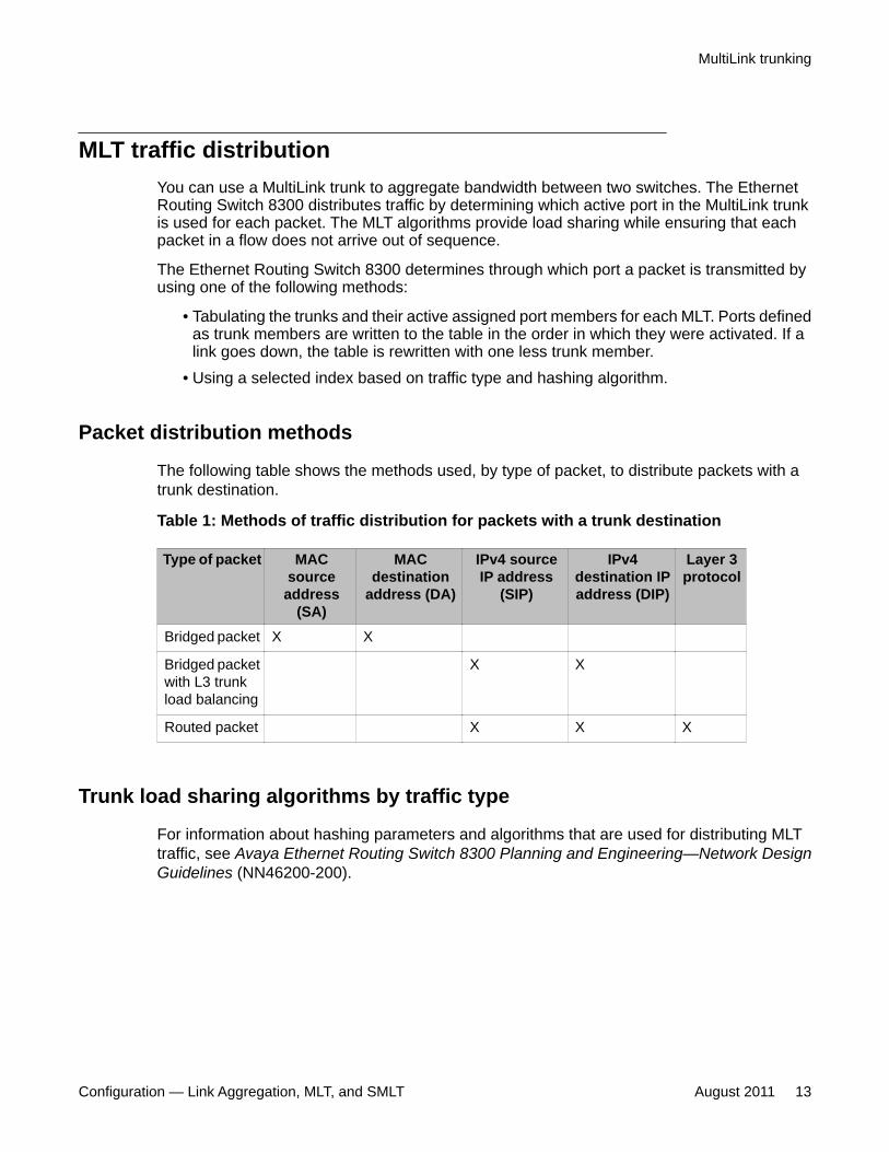
Packet distribution methods
The following table shows the methods used, by type of packet, to distribute packets with atrunk destination.
Table 1: Methods of traffic distribution for packets with a trunk destination
Type of packet MACsourceaddress
(SA)
MACdestination
address (DA)
IPv4 sourceIP address
(SIP)
IPv4destination IPaddress (DIP)
Layer 3protocol
Bridged packet X X
Bridged packetwith L3 trunkload balancing
X X
Routed packet X X X
Trunk load sharing algorithms by traffic type
For information about hashing parameters and algorithms that are used for distributing MLTtraffic, see Avaya Ethernet Routing Switch 8300 Planning and Engineering—Network DesignGuidelines (NN46200-200).
MultiLink trunking
Configuration — Link Aggregation, MLT, and SMLT August 2011 13
MLT and MLT with LACP configuration rulesEthernet Routing Switch 8300 MultiLink trunks adhere to the following rules. The rules alsoapply to MLT with LACP.
• MLT is supported on 10BASE-T, 100BASE-TX, 100Base-FX, Gigabit Ethernet, and 10Gigabit Ethernet module ports.
• All MultiLink trunk ports must have the same speed and duplex settings, even when auto-negotiation is set.
• The media type of MLT ports can be different; a mix of copper and fiber are allowed.
• All MultiLink trunk ports must be in the same STG unless the port is tagged. Taggingallows ports to belong to multiple STGs, as well as multiple VLANs.
• MLT is compatible with Spanning Tree Protocol (STP), Multiple Spanning Tree Protocol(MSTP) (IEEE 802.1s), and Rapid Spanning Tree Protocol (RSTP) (IEEE 802.1w).
• Tagging (IEEE 802.1Q) is supported on a MultiLink trunk.
• MLT ports can span modules, providing module redundancy.
• Apply filters individually to each port in a MultiLink trunk.
Ethernet Routing Switch 8300 MultiLink trunks have the following module specificrequirements:
• For 8348TX, 8348TX-PWR, and 8324FX ports, you can use only link aggregation groups1 to 7.
• For 8348GB, 8324GTX, 8324GTX-PWR, 8348GTX, and 8348GTX-PWR ports, as wellas 8308XL, 8393SF, and 8394SF, you can use link aggregation groups 1 to 31.
With the STP enabled, ports in the same MultiLink trunk operate as follows:
• Each port sends identical Bridge Protocol Data Unit (BPDU).
• The MultiLink trunk port ID is the ID of the lowest numbered port.
• If identical BPDUs are received on all ports, the MultiLink trunk mode is forwarding. Youcan disable the Avaya STP (ntstg <enable|disable>) if you do not want to receiveBPDUs on all ports.
• If ports do not receive BPDUs on a port or BPDU and port tagging do not match, theindividual port is taken offline.
• Path cost is inversely proportional to the active MultiLink trunk bandwidth.
Link aggregation fundamentals
14 Configuration — Link Aggregation, MLT, and SMLT August 2011Comments? [email protected]
LAG rulesThe Ethernet Routing Switch 8300 link aggregation group (LAG) adheres to the following rules:
• All LAG ports operate in full-duplex mode.
• All LAG ports operate at the same data rate.
• Assign all LAG ports in the same VLANs.
• Link aggregation is compatible with the STP, MSTP, and RSTP.
• Assign all ports in an LAG to the same STP groups.
• Ports in an LAG can exist on different modules.
• For Gigabit and 10 Gigabit ports, you can use link aggregation groups 1 to 31.
• For Fast Ethernet ports, you can use link aggregation groups 1 to 7 only.
• Each LAG supports a maximum of eight active links.
• Each LAG supports a maximum of eight standby links.
• After a MultiLink trunk is configured with LACP, you cannot add or delete ports or VLANsmanually without first disabling LACP.
MLT network topology and configuration examplesThe following reference information contains examples of MLT network topology andconfiguration. The same topologies apply to MLT with LACP.
MLT network topology and configuration examples navigation
• Example 1: Switch-to-switch MLT example on page 15
• Example 2: Switch-to-server MLT example on page 16
• Example 3: Client/server link aggregation configuration on page 17
Example 1: Switch-to-switch MLT example
Figure 1: Switch-to-switch MultiLink trunks configuration on page 16 shows two trunks (T1and T2) connecting switch S1 to switches S2 and S3.
MultiLink trunking
Configuration — Link Aggregation, MLT, and SMLT August 2011 15
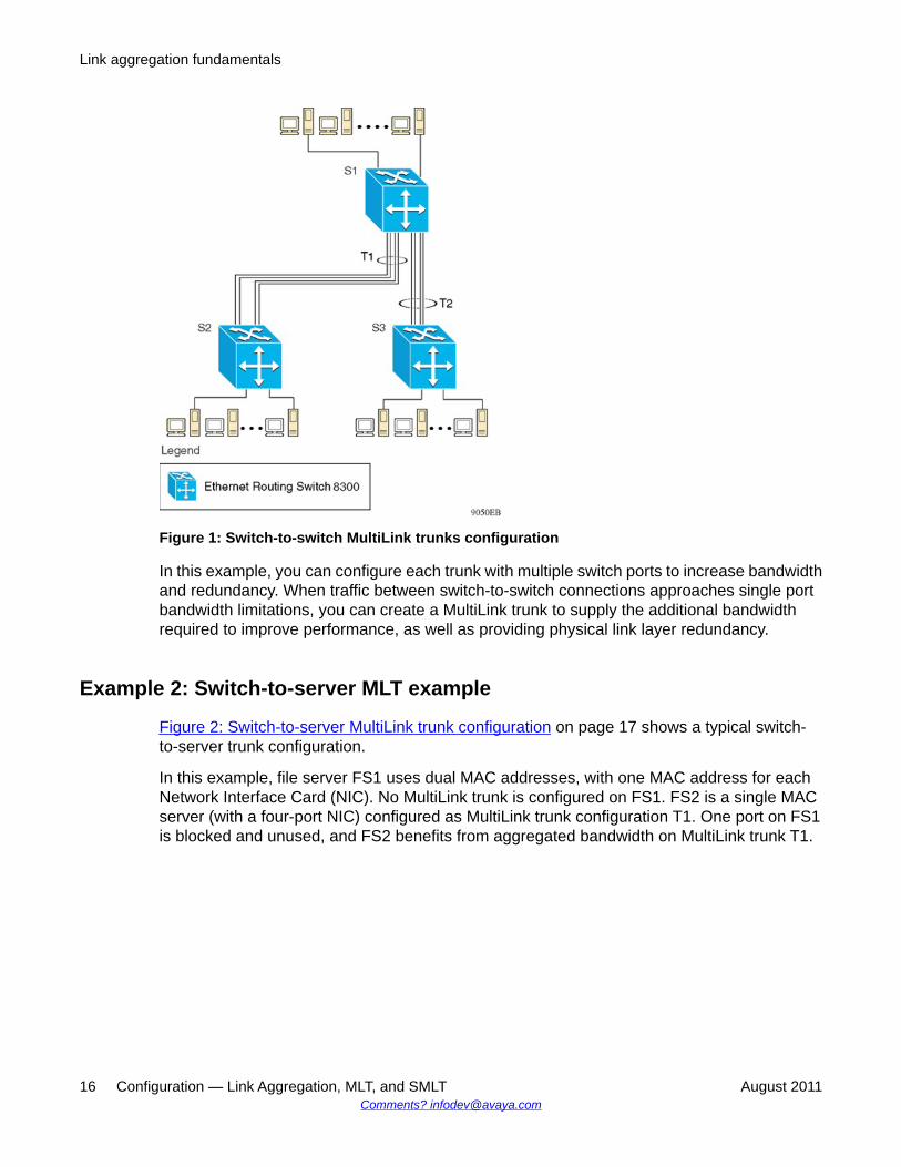
Figure 1: Switch-to-switch MultiLink trunks configuration
In this example, you can configure each trunk with multiple switch ports to increase bandwidthand redundancy. When traffic between switch-to-switch connections approaches single portbandwidth limitations, you can create a MultiLink trunk to supply the additional bandwidthrequired to improve performance, as well as providing physical link layer redundancy.
Example 2: Switch-to-server MLT example
Figure 2: Switch-to-server MultiLink trunk configuration on page 17 shows a typical switch-to-server trunk configuration.
In this example, file server FS1 uses dual MAC addresses, with one MAC address for eachNetwork Interface Card (NIC). No MultiLink trunk is configured on FS1. FS2 is a single MACserver (with a four-port NIC) configured as MultiLink trunk configuration T1. One port on FS1is blocked and unused, and FS2 benefits from aggregated bandwidth on MultiLink trunk T1.
Link aggregation fundamentals
16 Configuration — Link Aggregation, MLT, and SMLT August 2011Comments? [email protected]
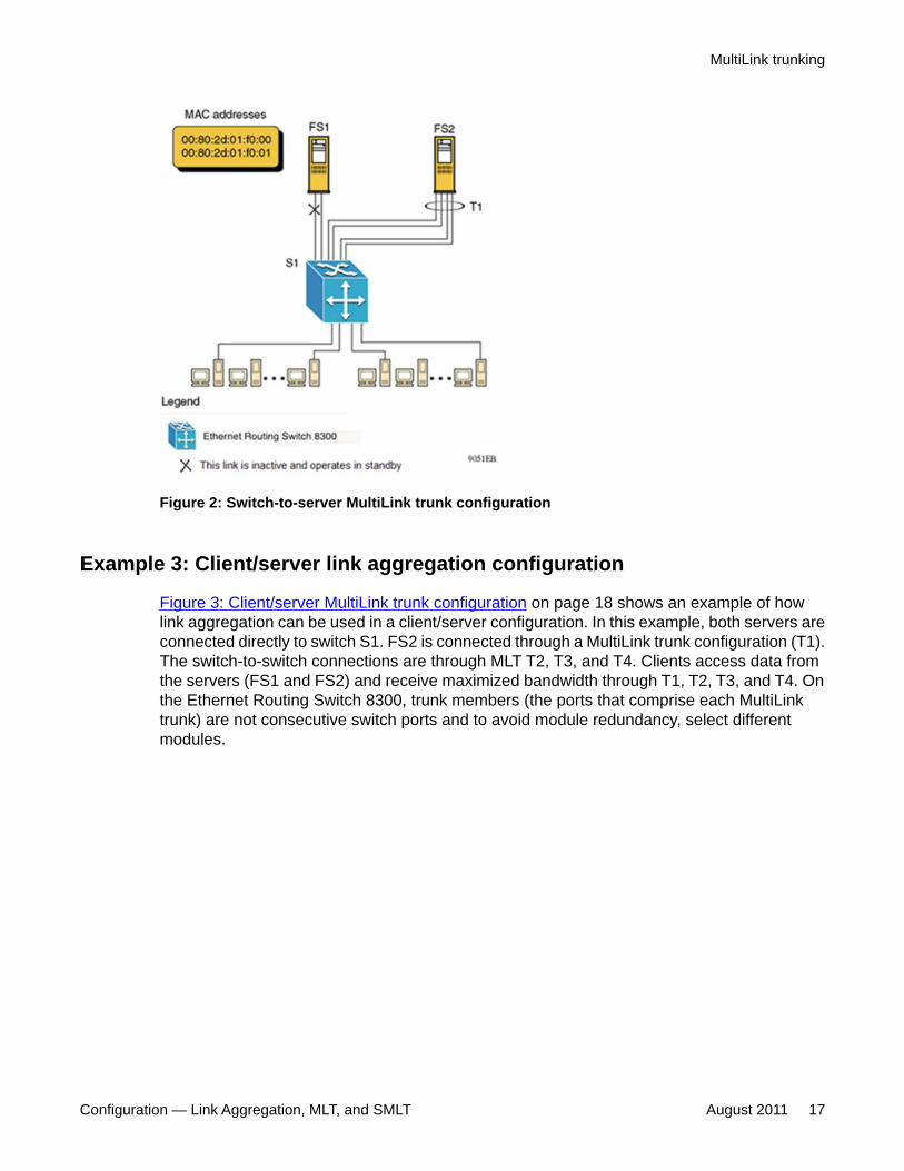
Figure 2: Switch-to-server MultiLink trunk configuration
Example 3: Client/server link aggregation configuration
Figure 3: Client/server MultiLink trunk configuration on page 18 shows an example of howlink aggregation can be used in a client/server configuration. In this example, both servers areconnected directly to switch S1. FS2 is connected through a MultiLink trunk configuration (T1).The switch-to-switch connections are through MLT T2, T3, and T4. Clients access data fromthe servers (FS1 and FS2) and receive maximized bandwidth through T1, T2, T3, and T4. Onthe Ethernet Routing Switch 8300, trunk members (the ports that comprise each MultiLinktrunk) are not consecutive switch ports and to avoid module redundancy, select differentmodules.
MultiLink trunking
Configuration — Link Aggregation, MLT, and SMLT August 2011 17
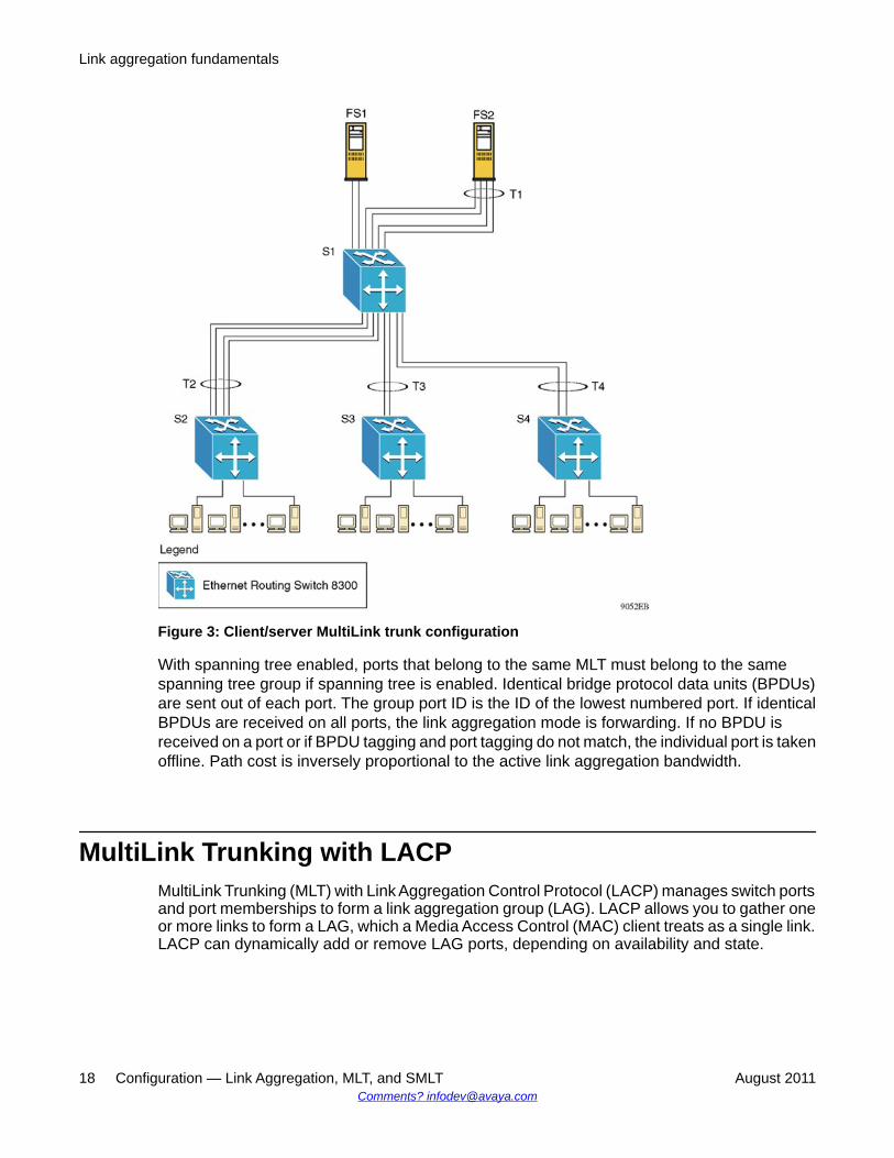
Figure 3: Client/server MultiLink trunk configuration
With spanning tree enabled, ports that belong to the same MLT must belong to the samespanning tree group if spanning tree is enabled. Identical bridge protocol data units (BPDUs)are sent out of each port. The group port ID is the ID of the lowest numbered port. If identicalBPDUs are received on all ports, the link aggregation mode is forwarding. If no BPDU isreceived on a port or if BPDU tagging and port tagging do not match, the individual port is takenoffline. Path cost is inversely proportional to the active link aggregation bandwidth.
MultiLink Trunking with LACPMultiLink Trunking (MLT) with Link Aggregation Control Protocol (LACP) manages switch portsand port memberships to form a link aggregation group (LAG). LACP allows you to gather oneor more links to form a LAG, which a Media Access Control (MAC) client treats as a single link.LACP can dynamically add or remove LAG ports, depending on availability and state.
Link aggregation fundamentals
18 Configuration — Link Aggregation, MLT, and SMLT August 2011Comments? [email protected]
IEEE 802.3ad overviewThe IEEE 802.3ad standard comprises service interfaces, the LACP, the Marker Protocol, linkaggregation selection logic, a parser/multiplexer, frame distribution, and frame collectionfunctions.
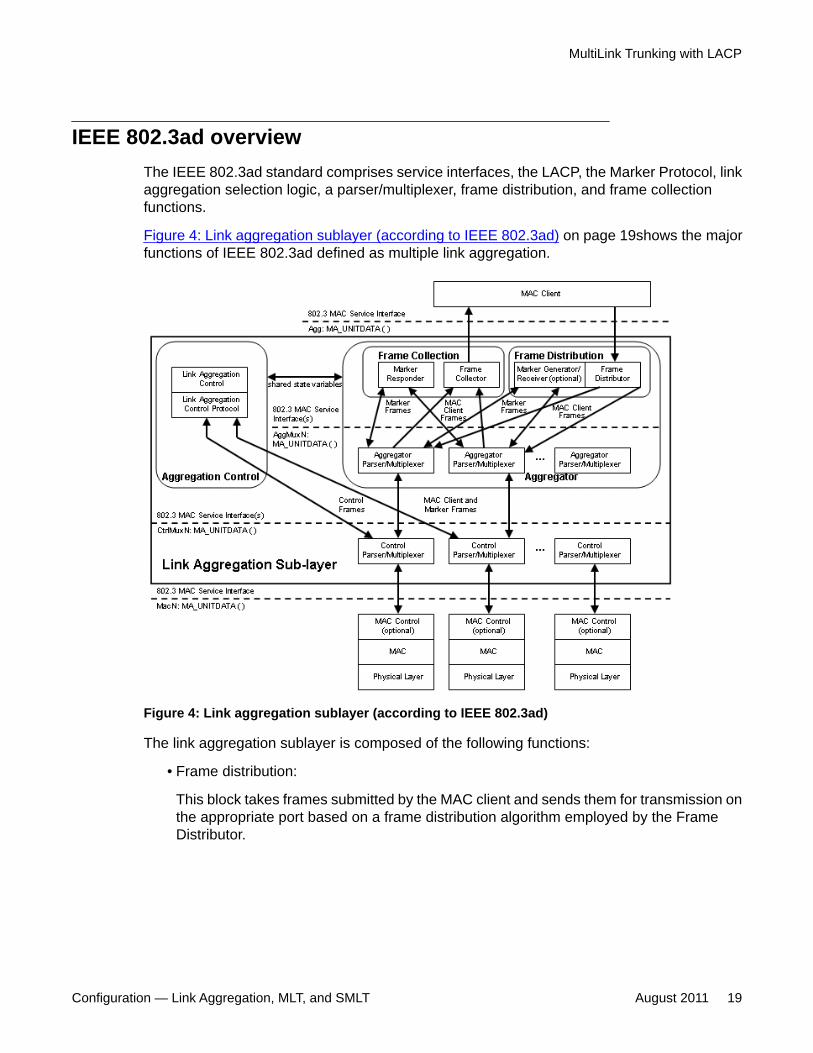
Figure 4: Link aggregation sublayer (according to IEEE 802.3ad) on page 19shows the majorfunctions of IEEE 802.3ad defined as multiple link aggregation.
Figure 4: Link aggregation sublayer (according to IEEE 802.3ad)
The link aggregation sublayer is composed of the following functions:
• Frame distribution:
This block takes frames submitted by the MAC client and sends them for transmission onthe appropriate port based on a frame distribution algorithm employed by the FrameDistributor.
MultiLink Trunking with LACP
Configuration — Link Aggregation, MLT, and SMLT August 2011 19
Frame distribution also includes an optional Marker Generator or Receiver used for theMarker Protocol. Ethernet Routing Switch 8300, only implements the Marker Receiverfunction.
• Frame collection:
This block passes frames received from the various ports to the MAC client. Framecollection also includes a Marker Responder which is used for the Marker Protocol.
• Aggregator Parser/Multiplexers:
During transmission operations, these blocks pass frame transmission requests from theDistributor, Marker Generator, and Marker Responder to the appropriate port.
During receive operations, these blocks distinguish among Marker Request, MarkerResponse, MAC Client Protocol Data Units (PDUs), and pass the blocks to theappropriate entity (Marker Responder, Marker Receiver, and Collector, respectively).
• Aggregator:
The combination of frame distribution and collection, and aggregator Parser/Multiplexers.
• Aggregation Control:
This block configures and controls link aggregation. It incorporates LACP for theautomatic communication of aggregation capabilities between systems and automaticconfiguration of link aggregation.
• Control Parser/Multiplexers:
During transmission operations, these blocks pass frame transmission requests from theaggregator and Control entities to the appropriate port.
During receive operations, these blocks distinguish Link Aggregation Control ProtocolData Units (LACPDUs) from other frames. The blocks pass, passing the LACPDUs to theappropriate sublayer entity and all other frames to the aggregator.
802.3ad link aggregation principlesLink aggregation allows you to group switch ports together to form a link group to anotherswitch or server. Link groups increase aggregate throughout between devices and provide linkredundancy.
Link aggregation fundamentals
20 Configuration — Link Aggregation, MLT, and SMLT August 2011Comments? [email protected]

Link aggregation employs the following principles and concepts:
• A MAC client communicates with a set of ports through an aggregator, which presents astandard IEEE 802.3 service interface to the MAC client. The aggregator binds to one ormore ports within a system.
• The aggregator distributes frame transmissions from the MAC client to various ports,collects received frames from the ports, and transparently passes the frames to the MACclient.
• A system can contain multiple aggregators serving multiple MAC clients. A port binds toa single aggregator at a time. A MAC client is served by a single aggregator at a time.
• The Link Aggregation Control function binds ports to aggregators within a system. Thecontrol function aggregates links, binds the system ports to an appropriate aggregator,and monitors conditions to determine when a change in aggregation is needed. Networkmanagers can manually provide link aggregation control by manipulating the linkaggregation state variables (for example, keys). You can also use LACP to automaticallydetermine, configure, bind, and monitor link aggregation.
• The LACP uses peer exchanges across links to continually determine the aggregationcapability of the links and provide the maximum level of aggregation capability betweena pair of systems.
• Frame ordering is maintained for certain sequences of frame exchanges between MACClients. The distributor ensures that all frames of a conversation pass to a single port.The collector passes frames to the MAC client in the order they are received from theport. The collector can select frames received from the aggregated ports in any order.Since the frames are not ordered on a single link, this guarantees that frame ordering ismaintained for any conversation.
• Conversations move among ports within an aggregation for load balancing and formaintaining availability if a link fails.
• The standard does not impose any particular distribution algorithm on the distributor.
• Each port is assigned a unique, globally administered MAC address.
When entities initiate frame exchanges within the link aggregation sublayer, the sourceaddress is the MAC address. An exmaple of an entity that initiates frame exchanges isLACP and Marker Protocol exchanges.
• Each aggregator is assigned a unique, globally administered MAC address that is usedfrom the perspective of the MAC client, both as a source address for transmitted framesand as the destination address for received frames. You can use one of the port MACaddresses in the associated LAG as the MAC address of the aggregator.
MultiLink Trunking with LACP
Configuration — Link Aggregation, MLT, and SMLT August 2011 21

Split MultiLink TrunkingSMLT is an option that improves Layer 2 and Layer 3 resiliency. The following sections discussSMLT in more detail.
Split MultiLink Trunking navigation
• SMLT overview on page 22
• SMLT versus STP on page 23
• SMLT topologies on page 24
• SMLT and Interswitch trunking on page 24
• SMLT and IST traffic flow example on page 27
• Single port SMLT on page 28
• MLT-based SMLT with single port SMLT on page 30
• SMLT and LACP support on page 31
• SMLT and IP routing on page 32
• SMLT and SLPP on page 34
• SMLT network design considerations on page 34
SMLT overviewSplit MultiLink Trunking (SMLT) is an option that improves Layer 2 (bridged) resiliency byproviding for the addition of switch failure redundancy with sub-second failover, on top of allstandard MLT link failure protection and flexible bandwidth scaling functionality. SMLT allowsyou to connect any device which supports some form of link aggregation, be it a switch or aserver, to two distinct separate SMLT endpoints or switches. These SMLT switches form aSwitch Cluster and are referred to as an IST Core Switch pair.
Switch Clusters are always formed as a pair, but pairs of clusters can be combined in either asquare of full-mesh fashion to increase the size and port density of the Switch Cluster. Whenconfigured in a Layer 3 or routed topology, the configuration is referenced as Routed SMLT(RSMLT). For information about Routed SMLT, see Avaya Ethernet Routing Switch 8300Configuration — IP Routing (NN46200-518).
Important:Before you reboot a switch that is the LACP master, you must configure the LACP systemID globally to prevent an RSMLT failure. For more information, see Configuring LACP
Link aggregation fundamentals
22 Configuration — Link Aggregation, MLT, and SMLT August 2011Comments? [email protected]

globally using Device Manager on page 44,Configuring LACP globally using the CLI onpage 72, or Configuring LACP globally using the ACLI on page 100
SMLT connections can be formed via single links from the switch cluster to the edgeconnection, Single Link SMLT (SLT), or via standard MLTs, or MLTs with LACP. Optionally,SMLT links can have VLACP enabled as well. These various link connections can be mixed.Within the same Switch Cluster, both SMLT and RSMLT can be configured, allowing a mixtureof both Layer 2 and Layer 3 VLANs. For examples of various SMLT configurations, see SMLTtopologies on page 24.
SMLT networks do not need to use the IEEE 802.1d STP to enable loop-free triangle topologiesbecause SMLT inherently avoids loops due to its superior enhanced link aggregation protocol.This is accomplished by implementing a method that allows two aggregation switches toappear as a single device to edge switches, which dual-home to the aggregation switches.The aggregation switches interconnect using an interswitch trunk, which allows them toexchange addressing and state information (permitting rapid fault detection and forwardingpath modification). SMLT is designed for Layer 2 network connectivity, but can be configuredin Layer 3 networks by working with VRRP.
SMLT advantages
SMLT eliminates all single points of failure and creates multiple paths from all user accessswitches to the network core. In case of failure, SMLT recovers as quickly as possible usingall capacity. SMLT provides a transparent and interoperable solution that requires nomodification on the part of the majority of existing user access devices.
SMLT improves the reliability of Layer 2 (L2) networks that operate between user accessswitches and the network center aggregation switch by providing:
• load sharing among all links• fast failover in case of link failures• elimination of single point of failure• fast recovery in case of nodal failure• transparent and interoperable solutions• removal of STP convergence issues
SMLT versus STPNetworks designed to have user access switches dual-home to two aggregation switches, andhave VLANs spanning two or more user access switches, experience the following designconstraints:
• No load sharing exists over redundant links.
• Network convergence is slow in case of failure.
Split MultiLink Trunking
Configuration — Link Aggregation, MLT, and SMLT August 2011 23
With the introduction of SMLT, all dual-home Layer 2 frame-switched network devices with dualhomes are no longer dependent on the STP for loop detection. A properly designed SMLTnetwork inherently does not have any logical loops.
SMLT solves the spanning tree problem by combining two aggregation switches into onelogical MLT entity, thus making it transparent to any type of edge switch. In the process, itprovides quick convergence, while load sharing across all available trunks.
SMLT topologiesThere are four generic topologies in which you can deploy SMLT:
• a Single Port SMLT configuration• a triangle configuration• a square configuration• a full-mesh configuration (depending on the resiliency and redundancy required)
For information about SMLT topologies and what topologies are supported per product, seeSwitch Clustering (SMLT/SLT/RSMLT/MSMLT) Supported Topologies and Interoperability withERS 8800/8600 / 5500 / 8300 / 1600, (NN48500-555).
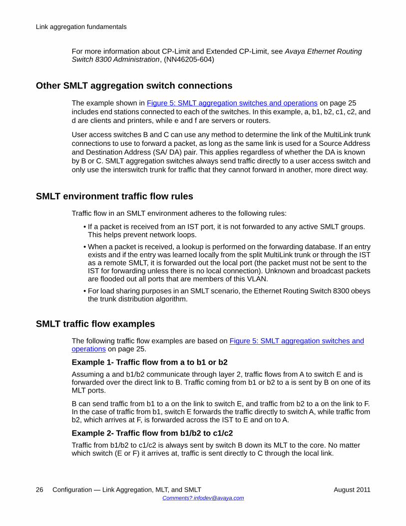
SMLT and Interswitch trunkingFigure 5: SMLT aggregation switches and operations on page 25illustrates an SMLTconfiguration with a pair of Ethernet Routing Switch 8300 switches (E and F) as aggregationswitches and four separate user access switches (A, B, C, and D).
You must connect SMLT aggregation switches through an interswitch trunk. For example, useraccess switches B and C connect to the aggregation switches through MultiLink trunks splitbetween the two aggregation switches. As shown in Figure 5: SMLT aggregation switches andoperations on page 25, the implementation of SMLT only requires two SMLT-capableaggregation switches. You must connect these switches through an interswitch trunk.
Link aggregation fundamentals
24 Configuration — Link Aggregation, MLT, and SMLT August 2011Comments? [email protected]
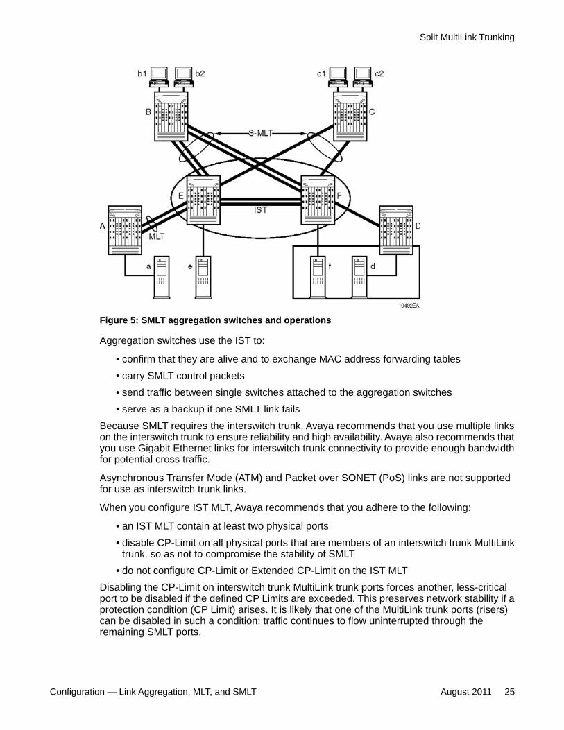
Figure 5: SMLT aggregation switches and operations
Aggregation switches use the IST to:
• confirm that they are alive and to exchange MAC address forwarding tables• carry SMLT control packets• send traffic between single switches attached to the aggregation switches• serve as a backup if one SMLT link fails
Because SMLT requires the interswitch trunk, Avaya recommends that you use multiple linkson the interswitch trunk to ensure reliability and high availability. Avaya also recommends thatyou use Gigabit Ethernet links for interswitch trunk connectivity to provide enough bandwidthfor potential cross traffic.
Asynchronous Transfer Mode (ATM) and Packet over SONET (PoS) links are not supportedfor use as interswitch trunk links.
When you configure IST MLT, Avaya recommends that you adhere to the following:
• an IST MLT contain at least two physical ports• disable CP-Limit on all physical ports that are members of an interswitch trunk MultiLink
trunk, so as not to compromise the stability of SMLT• do not configure CP-Limit or Extended CP-Limit on the IST MLT
Disabling the CP-Limit on interswitch trunk MultiLink trunk ports forces another, less-criticalport to be disabled if the defined CP Limits are exceeded. This preserves network stability if aprotection condition (CP Limit) arises. It is likely that one of the MultiLink trunk ports (risers)can be disabled in such a condition; traffic continues to flow uninterrupted through theremaining SMLT ports.
Split MultiLink Trunking
Configuration — Link Aggregation, MLT, and SMLT August 2011 25
For more information about CP-Limit and Extended CP-Limit, see Avaya Ethernet RoutingSwitch 8300 Administration, (NN46205-604)
Other SMLT aggregation switch connections
The example shown in Figure 5: SMLT aggregation switches and operations on page 25includes end stations connected to each of the switches. In this example, a, b1, b2, c1, c2, andd are clients and printers, while e and f are servers or routers.
User access switches B and C can use any method to determine the link of the MultiLink trunkconnections to use to forward a packet, as long as the same link is used for a Source Addressand Destination Address (SA/ DA) pair. This applies regardless of whether the DA is knownby B or C. SMLT aggregation switches always send traffic directly to a user access switch andonly use the interswitch trunk for traffic that they cannot forward in another, more direct way.
SMLT environment traffic flow rules
Traffic flow in an SMLT environment adheres to the following rules:
• If a packet is received from an IST port, it is not forwarded to any active SMLT groups.This helps prevent network loops.
• When a packet is received, a lookup is performed on the forwarding database. If an entryexists and if the entry was learned locally from the split MultiLink trunk or through the ISTas a remote SMLT, it is forwarded out the local port (the packet must not be sent to theIST for forwarding unless there is no local connection). Unknown and broadcast packetsare flooded out all ports that are members of this VLAN.
• For load sharing purposes in an SMLT scenario, the Ethernet Routing Switch 8300 obeysthe trunk distribution algorithm.
SMLT traffic flow examples
The following traffic flow examples are based on Figure 5: SMLT aggregation switches andoperations on page 25.
Example 1- Traffic flow from a to b1 or b2Assuming a and b1/b2 communicate through layer 2, traffic flows from A to switch E and isforwarded over the direct link to B. Traffic coming from b1 or b2 to a is sent by B on one of itsMLT ports.
B can send traffic from b1 to a on the link to switch E, and traffic from b2 to a on the link to F.In the case of traffic from b1, switch E forwards the traffic directly to switch A, while traffic fromb2, which arrives at F, is forwarded across the IST to E and on to A.
Example 2- Traffic flow from b1/b2 to c1/c2Traffic from b1/b2 to c1/c2 is always sent by switch B down its MLT to the core. No matterwhich switch (E or F) it arrives at, traffic is sent directly to C through the local link.
Link aggregation fundamentals
26 Configuration — Link Aggregation, MLT, and SMLT August 2011Comments? [email protected]

Example 3- Traffic flow from a to dTraffic from a to d (and d to a) is forwarded across the IST because it is the shortest path. Thispath is treated purely as a standard link; SMLT and IST parameters are not considered.
Example 4- Traffic flow from f to c1/c2Traffic from f to c1/c2 is sent out directly from F. With respect to return traffic from c1/c2, youcan have one active Virtual Router Redundancy Protocol (VRRP) Master for each IP subnet.Traffic is passed across the IST if switch C sends it to E.
SMLT and IST traffic flow exampleIn an SMLT environment, the two aggregation switches share the same forwarding databaseby exchanging forwarding entries using the IST. In Figure 7: Output of the command show vlanfdb-e 10 on page 28, the forwarding databases are shown for a pair of IST nodes (B and C).The entry for 00:E0:7B:B3:04:00 is shown on node C as being learned on MLT-1, but becauseSMLT REMOTE is true, this entry is actually learned from node B. On B that same entry isshown as being directly learned through MLT-1 because SMLT REMOTE is false. Figure 6:Network topology for traffic flow example on page 27 shows the network topology.
Figure 6: Network topology for traffic flow example
When a packet arrives at node C destined for 00:E0:7B:B3:04:00, if the SMLT REMOTE istrue, the switch tries to send the packet out MLT-1 first, rather than through the IST unlessthere is a failure. Traffic rarely traverses the IST unless there is a failure. If this same packetarrives at B, it is forwarded to MLT-1 on the local ports.
Split MultiLink Trunking
Configuration — Link Aggregation, MLT, and SMLT August 2011 27
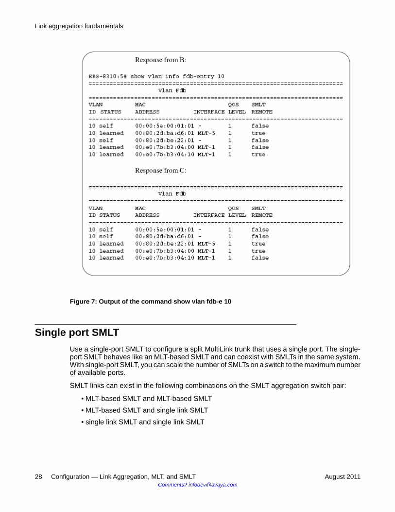
Figure 7: Output of the command show vlan fdb-e 10
Single port SMLTUse a single-port SMLT to configure a split MultiLink trunk that uses a single port. The single-port SMLT behaves like an MLT-based SMLT and can coexist with SMLTs in the same system.With single-port SMLT, you can scale the number of SMLTs on a switch to the maximum numberof available ports.
SMLT links can exist in the following combinations on the SMLT aggregation switch pair:
• MLT-based SMLT and MLT-based SMLT• MLT-based SMLT and single link SMLT• single link SMLT and single link SMLT
Link aggregation fundamentals
28 Configuration — Link Aggregation, MLT, and SMLT August 2011Comments? [email protected]
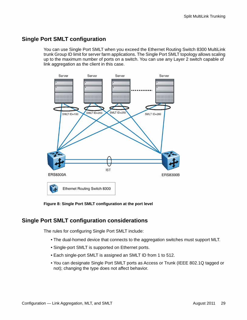
Single Port SMLT configuration
You can use Single Port SMLT when you exceed the Ethernet Routing Switch 8300 MultiLinktrunk Group ID limit for server farm applications. The Single Port SMLT topology allows scalingup to the maximum number of ports on a switch. You can use any Layer 2 switch capable oflink aggregation as the client in this case.
Figure 8: Single Port SMLT configuration at the port level
Single Port SMLT configuration considerations
The rules for configuring Single Port SMLT include:
• The dual-homed device that connects to the aggregation switches must support MLT.
• Single-port SMLT is supported on Ethernet ports.
• Each single-port SMLT is assigned an SMLT ID from 1 to 512.
• You can designate Single Port SMLT ports as Access or Trunk (IEEE 802.1Q tagged ornot); changing the type does not affect behavior.
Split MultiLink Trunking
Configuration — Link Aggregation, MLT, and SMLT August 2011 29
• You cannot change a Single Port split MultiLink trunk to an MLT-based split MultiLink trunkby adding additional ports. You must delete the single port split MultiLink trunk andreconfigure the port as SMLT/MLT.
• You cannot change an MLT-based split MultiLink trunk into a single port split MultiLinktrunk by deleting all ports except one. You must remove the SMLT/MLT and reconfigurethe port as Single Port SMLT.
• You cannot configure a port as an MLT-based SMLT and as single-port SMLT at the sametime.
• Two or more aggregation switches can have single port Split MultiLink trunk with the sameIDs. You can have as many single port Split MultiLink trunk as there are available portson the switch.
• LACP is supported on single port SMLT.
MLT-based SMLT with single port SMLTYou can configure a split MultiLink trunk with a single port SMLT on one side and an MLT-basedSMLT on the other. Both must have the same SMLT ID. In addition to general use, Figure 9:Changing a split trunk from MLT-based SMLT to single-port SMLT on page 31 shows howthis configuration can be used to upgrade an MLT-based SMLT to a single-port SMLT withoutinterrupting the split trunk.
Assuming that the MLT ID is 10, the steps are:
1. Configure switch A and B with MTL-based SMLT.
2. Disable all ports and then delete MLT-based SMLT 10 on switch B. All trafficswitched over to SMLT 10 on switch A.
3. Configure single port SMLT ID 10 on switch B and enable the port. Traffic switchesover both sides of the split trunk.
4. Disable all ports and delete MLT-based SMLT 10 on switch A. All traffic switchesover single port SMLT 10 on switch B.
5. Configure single port SMLT 10 on switch A and enable the port. Traffic switchesover both sides of the split trunk.
Link aggregation fundamentals
30 Configuration — Link Aggregation, MLT, and SMLT August 2011Comments? [email protected]
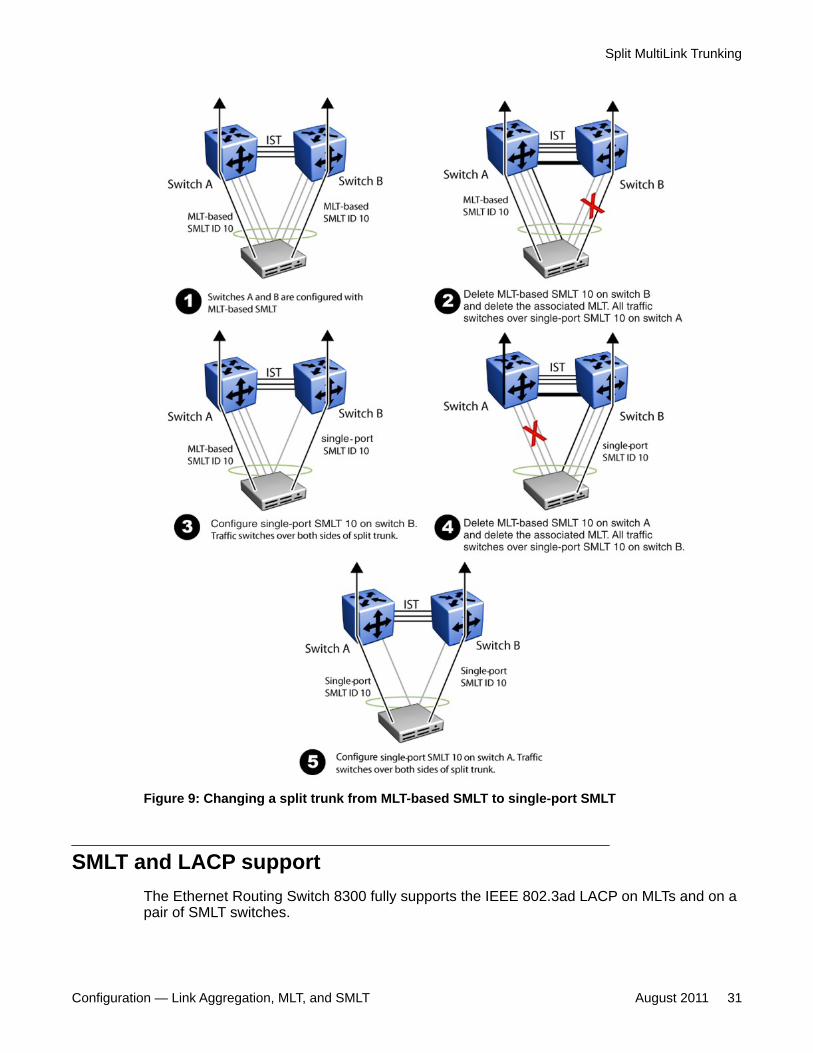
Figure 9: Changing a split trunk from MLT-based SMLT to single-port SMLT
SMLT and LACP supportThe Ethernet Routing Switch 8300 fully supports the IEEE 802.3ad LACP on MLTs and on apair of SMLT switches.
Split MultiLink Trunking
Configuration — Link Aggregation, MLT, and SMLT August 2011 31
With LACP the Ethernet Routing Switch 8300 provides a standardized external linkaggregation interface to third-party vendor IEEE 802.3ad implementations. This protocolextension provides dynamic link aggregation mechanisms. Only dual-home devices benefitfrom this enhancement.
Advantages of this protocol extension include:
• MLT peers and SMLT client devices can be both network switches and any type of server/workstation that supports link bundling through IEEE 802.3ad.
• Single-link and MultiLink trunk solutions support dual-home connectivity for more than350 attached devices, so that you can build dual-home server farm solutions.
Supported SMLT/LACP scenarios
SMLT/IEEE link aggregation interaction supports all known SMLT scenarios in which an IEEE802.3ad SMLT pair connects to SMLT clients, or in which two IEEE 802.3ad SMLT pairsconnect to each other in a square or full-mesh topology.
Unsupported SMLT/LACP scenarios
Some of the unsupported SMLT/LACP scenarios include the following factors, which lead tofailure:
• Incorrect port connections.
• Mismatched SMLT IDs assigned to SMLT client. SMLT switches can detect if SMLT IDsare not consistent. The SMLT aggregation switch, which has the lower IP address, doesnot allow the SMLT port to become a member of the aggregation thereby avoidingmisconfigurations.
• SMLT client switch does not have automatic aggregation enabled (LACP disabled). SMLTaggregation switches can detect that aggregation is not enabled on the SMLT client, thusno automatic link aggregation is established until the configuration is resolved.
• Single CPU failures. In the case of a CPU failure in a system with only one switch fabric,the LACP on the other switch (or switches) detects the remote failure and triggers removalof links connected to the failed system from the LAG. This process allows failure recoveryfor the network along a different network path.
SMLT and IP routingThis section describes SMLT and IP routing interactions.
Link aggregation fundamentals
32 Configuration — Link Aggregation, MLT, and SMLT August 2011Comments? [email protected]
SMLT and the Virtual Router Redundancy Protocol
Using Virtual Router Redundancy Protocol (VRRP) you can have one active primary router foreach IP subnet, with all other network VRRP interfaces operating in backup mode.
The VRRP has only one active routing interface enabled. Users that access switchesaggregated into two SMLT switches send their shared traffic load (based on source anddestination MAC or IP addresses) on all uplinks towards the SMLT aggregation switches.
The VRRP is less efficient if you use it with SMLT. All other interfaces are in backup (standby)mode. In this case, all traffic is forwarded over the IST link towards the primary VRRP switch.All traffic that arrives at the VRRP backup interface is forwarded, so there is not enoughbandwidth on the IST link to carry all the aggregated riser traffic. However, an enhancementto VRRP overcomes this issue by ensuring that the IST trunk is not used in such a case forprimary data forwarding.
SMLT and VRRP Backup Master
The VRRP BackupMaster acts as an IP router for packets destined for the logical VRRP IPaddress. All traffic is directly routed to the destined subnetwork and not through Layer 2switches to the VRRP master. This avoids potential limitation in the available interswitch trunkbandwidth.
To avoid potential frame duplication problems, you can only use the VRRP BackupMasterfeature for SMLT on interfaces that are defined for SMLT. You cannot use VRRP BackupMasterwith hubs to avoid frame duplication or on brouter or VLAN interfaces.
When using an SMLT with routing on SMLT aggregation switches, Avaya recommends thatyou use VRRP for default gateway redundancy. In a VRRP environment, one switch is activeand the other is backup. In an SMLT environment, you can enable the VRRP BackupMasterand use an active–active concept. The VRRP BackupMaster router routes traffic that isreceived on the SMLT VLAN and avoid traffic flow across the interswitch trunk. This providestrue load-sharing abilities.
The BackupMaster feature provides an additional benefit. VRRP normally sends a hello packetevery second. When three hello packets are not received, all switches automatically revert tomaster mode. This results in a 3- second outage. When you use VRRP in an SMLTenvironment, and a link goes down, traffic is automatically forwarded to the remaining portsconfigured for SMLT VRRP BackupMaster. Because both switches are processing traffic, thenode immediately recognizes the VRRP state change, so there is faster failure recovery (lessthan 1 second).
Follow these guidelines when you use VRRP BackupMaster with SMLT:
• The VRRP virtual IP address and the VLAN IP address cannot be the same.• Configure the hold-down timer for VRRP to a value that is approximately 150 percent of
the Interior Gateway Protocol (IGP) convergence time to allow the IGP enough time toreconverge following a failure. For example, if OSPF takes 40 seconds to reconverge,configure the hold-down timer to 60 seconds.
Split MultiLink Trunking
Configuration — Link Aggregation, MLT, and SMLT August 2011 33

• Stagger the hold down timers with Address Resolution Protocol (ARP) requests. Thismeans that the Ethernet Routing Switch 8300 does not have to run ARP and SMLT at thesame time, causing excess CPU load. For example, if one node has the hold-down timerset for 60 seconds, you can set the other hold-down timer to 65 seconds.
• Enable hold down times on both VRRP sides (Master and BackupMaster).
SMLT and SLPPSimple Loop Prevention Protocol (SLPP) is used to prevent loops in a SMLT network. SLPPis focused on SMLT networks but works with other configurations. Avaya recommends thatyou always use SLPP in any SMLT environment. SLPP requires the use of 4.0.x code orhigher.
Do not enable SLPP Rx on IST MLT ports. You can enable SLPP on other non-SMLT ports ofany IST Core switch pair. The Ethernet Routing Switch 8300 does not support the use of SLPPin an SMLT that is using LACP.
For information about SLPP fundamentals and configuring SLPP, see Avaya Ethernet RoutingSwitch 8300 Administration (NN46200-604).
SMLT network design considerationsUse the following base guidelines when designing a SMLT network.
1. Define a separate VLAN for the IST protocol:
ERS-8300:5#config-mlt #ist ip <value> vlan <value>2. Enable tagging on split MultiLink trunk links:
ERS-8300:5#config ethernet <slot/port> perform tagging enable3. Enable dropping of untagged frames on split MultiLink trunk links:
ERS-8300:5#config ethernet <slot/port> untagged-frames-discard enable
Virtual Link Aggregation Control ProtocolVirtual Link Aggregation Control Protocol (VLACP) is an extension to LACP used for end-to-end failure detection. VLACP is not a link aggregation protocol, it is a mechanism to periodicallycheck the end-to-end health of a point-to-point connection. VLACP uses the Hello mechanismof LACP to periodically send Hello packets to ensure an end-to-end communication. WhenHello packets are not received, VLACP transitions to a failure state, which indicates a serviceprovider failure and that the port is disabled.
Link aggregation fundamentals
34 Configuration — Link Aggregation, MLT, and SMLT August 2011Comments? [email protected]
You can reduce VLACP timers to 200-ms, which allows one second failure detection andswitchover time. Ethernet Routing Switch 8300 Software Release 4.1 uses the followingVLACP timers:
• fast-periodic timer—200 to 20 000 ms; default 200 ms
Values are in multiple of 200 ms only.• slow-periodic timer—10 000 to 30 000 ms; default 30 000 ms
VLACP only works for port-to-port communications where there is a guarantee for a logicalport-to-port match through the service provider. VLACP does not work for port-to-multiportcommunications where there is no guarantee for a point-to-point match through the serviceprovider. You can configure VLACP on a port.
VLACPcan also be used with MLT to complement its capabilities and providequick failuredetection. VLACP is recommended for all SMLT accesslinks when the links are configured asMLT to ensure both end devicesare able to communicate. By using VLACP over Single-PortSMLT, enhancedfailure detection is extended beyond the limits of the number of SMLTor LACPinstances that can be created on an Avaya switch.
VLACP trap messages are sent to the management stations if the VLACP state changes. Ifthe failure is local, the only traps that are generated are port linkdown or port linkup.
The Ethernet cannot detect end-to-end failures. Extend the Ethernet to detect remote linkfailures through functions such as remote fault indication or far-end fault indicationmechanisms. A major limitation of the functions is that they terminate at the next Ethernet hop.They cannot determine failures on an end-to-end basis.
For example, in Figure 10: Problem description (1 of 2) on page 36when the Enterprisenetworks connect the aggregated Ethernet trunk groups through a service provider networkconnection (for example, through a VPN), far-end failures cannot be signaled with Ethernet-based functions that operate end-to-end through the service provider network. The MultiLinktrunk (between Enterprise switches S1 and S2) extends through the Service Provider (SP)network.
Figure 10: Problem description (1 of 2) on page 36 shows an MLT running with VLACP.VLACP can operate end-to-end, but can be used in a point-to-point link.
Virtual Link Aggregation Control Protocol
Configuration — Link Aggregation, MLT, and SMLT August 2011 35
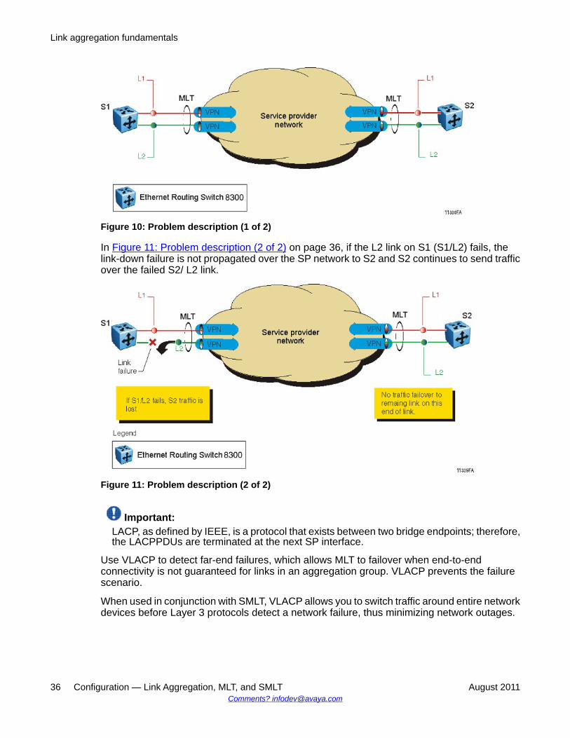
Figure 10: Problem description (1 of 2)
In Figure 11: Problem description (2 of 2) on page 36, if the L2 link on S1 (S1/L2) fails, thelink-down failure is not propagated over the SP network to S2 and S2 continues to send trafficover the failed S2/ L2 link.
Figure 11: Problem description (2 of 2)
Important:LACP, as defined by IEEE, is a protocol that exists between two bridge endpoints; therefore,the LACPPDUs are terminated at the next SP interface.
Use VLACP to detect far-end failures, which allows MLT to failover when end-to-endconnectivity is not guaranteed for links in an aggregation group. VLACP prevents the failurescenario.
When used in conjunction with SMLT, VLACP allows you to switch traffic around entire networkdevices before Layer 3 protocols detect a network failure, thus minimizing network outages.
Link aggregation fundamentals
36 Configuration — Link Aggregation, MLT, and SMLT August 2011Comments? [email protected]

Link aggregation configuration considerationsUse the information in this section to understand the considerations and guidelines whenconfiguring link aggregation into your network.
Link aggregation configuration considerations navigation
• MLT with LACP configuration considerations on page 37
• MLT with LACP and SMLT configuration considerations on page 38
• MLT with LACP and Spanning Tree configuration considerations on page 39
• LACP parameters configuration considerations on page 40
MLT with LACP configuration considerationsWhen you configure standard-based link aggregation, you must enable the aggregationparameter. After you enable the aggregation parameter, the LACP aggregator is mapped one-to-one to the specified MultiLink trunk.
Perform the following steps to configure an LAG:
1. Assign a numeric key to the ports you want to include in the LAG.
2. Configure port aggregation to true.
3. Enable LACP on the port.
4. Create an MultiLink trunk and assign the same key as in step 1 to it.
The MultiLink trunk/LAG only aggregates ports whose key matches its own.
The newly created MultiLink trunk or LAG adopts the VLAN membership of its member portswhen the first port is attached to the aggregator associated with this LAG. When a portdetaches from an aggregator, the associated LAG port deletes the member from its list.
After a MultiLink trunk is configured with LACP, you cannot add or delete ports or VLANsmanually without first disabling LACP.
To enable tagging on ports belonging to a LAG, disable LACP on the port and then enabletagging and LACP on the port.
If you enable Open Shortest Path First (OSPF) routing on a port, do not set the LACP periodictransmission timer to less than 1 second.
Link aggregation configuration considerations
Configuration — Link Aggregation, MLT, and SMLT August 2011 37

MLT with LACP and SMLT configuration considerationsSplit MultiLinkTrunks (SMLT) can be configured with MLT or MLT with LACP. Follow theseguidelines when you configure SMLT with LACP:
• When you set the LACP system ID for SMLT, configure the same LACP SMLT system IDon both aggregation switches to avoid the loss of data. Avaya recommends that youconfigure the LACP SMLT system ID to be the base MAC address of one of the aggregateswitches, and that you include the SMLT-ID. Ensure that the same System ID is configuredon both of the SMLT core aggregation switches.
• If you use LACP in an SMLT square configuration, the LACP ports must have the samekeys for that SMLT LAG; otherwise, the aggregation can fail if a switch fails.
• If an SMLT aggregation switch has LACP enabled on some of its MultiLink trunks, do notchange the LACP system priority. If some ports do not enter the desired MultiLink trunkafter a dynamic configuration change, enter the following CLI command: config mlt<mlt-id> lacp clear-link-aggrgate
• When you configure SMLT links, Avaya recommends that you set the multicast packets-per-second value to 6000 pps.
• Avaya recommends that you do not enable LACP on interswitch trunks to avoidunnecessary processing. Use VLACP if a failure detection mechanism is required whenthere is an optical network between the SMLT core switches.
Using the SMLT system ID enables you to use any third-party switch as a wiring closet switchin an SMLT configuration. This enhancement provides an option for the administrator toconfigure the SMLT Core Aggregation Switches to always use the system ID. In this way, theSMLT Core Aggregation Switch will always use the same LACP key regardless of the state ofSMLT Core Aggregation Switch neighbor (or the IST link). Therefore no change in LAGs shouldoccur on the attached device. This is the case regardless of whether the device is a server ora third-party switch. This situation does not affect Avaya edge switches used in SMLTconfigurations. The actor system priority of LACP_DEFAULT_SYS_PRIO, the actor system IDthe user configures, and an actor key equal to the SMLT-ID or SLT-ID are sent to the wiringcloset switch. Avaya recommends that you configure the system ID to be the base MACaddress of one of the aggregate switches along with its SMLT-id. The administrator mustensure that the same value for system ID is configured on both of the SMLT Core AggregationSwitches
The Ethernet Routing Switch 8300 software does not support the use of Simple LoopPrevention Protocol (SLPP) in an LACP–SMLT environment.
With Release 4.1 and higher, an administrator can configure the LACP SMLT System ID usedby SMLT core aggregation switches. When you set the LACP system ID for SMLT, configurethe same LACP SMLT system ID on both aggregation switches to avoid the loss of data.
An explanation of the importance of configuring the System ID is as follows. The LACP SystemID is the base MAC address of the switch, which is carried in Link Aggregation Control ProtocolData Units (LACPDU). When two links interconnect two switches that run LACP, each switch
Link aggregation fundamentals
38 Configuration — Link Aggregation, MLT, and SMLT August 2011Comments? [email protected]
knows that both links connect to the same remote device because the LACPDUs originatefrom the same System ID. If the links are enabled for aggregation using the same key, thenLACP can dynamically aggregate them into a LAG (MLT).
When SMLT is used between the two switches, they act as one logical switch. Both aggregationswitches must use the same LACP System ID over the SMLT links so that the edge switchsees one logical LACP peer, and can aggregate uplinks towards the SMLT aggregationswitches. This process automatically occurs over the IST connection, where the base MACaddress of one of the SMLT aggregation switches is chosen and used by both SMLTaggregation switches.
However, if the switch that owns that Base MAC address reboots, the IST goes down, and theother switch reverts to using its own Base MAC address as the LACP System ID. This actioncauses all edge switches that run LACP to think that their links are connected to a differentswitch. The edge switches stop forwarding traffic on their remaining uplinks until theaggregation can reform (which can take several seconds). Additionally, when the rebootedswitch comes back on line, the same actions occur, thus disrupting traffic twice.
The solution to this problem is to statically configure the same SMLT System ID MAC addresson both aggregation switches.
MLT with LACP and Spanning Tree configuration considerationsOnly the physical link state or its LACP peer status affects LACP module operation. When alink is enabled or disabled, an LACP module is notified. STP forwarding state does not affectLACP module operation. LACPDUs can be sent if the port is in an STP blocking state.
Unlike legacy MultiLink trunks, configuration changes (such as speed and duplex mode) to aLAG member port are not applied to all member ports in the MultiLink trunks. The changedport is removed from the LAG and the corresponding aggregator, and the user is alerted whenthe configuration is created.
In contrast to MLT, MLT with LACP does not expect BPDUs to be replicated over all ports inthe trunk group. Therefore, you must enter the ntstg disable command to disable theparameter on the Spanning Tree Group (STG) for LACP-based link aggregation. For moreinformation about this command, see Avaya Ethernet Routing Switch 8300 Configuration —VLANs and Spanning Tree, NN46200-516.
ntstg disable parameter is applicable to all trunk groups that are members of the STG.This is applicable when internetworking with devices only send BPDUs out of one port of theLAG.
Important:LACP, as defined by IEEE, is a protocol that exists between two bridge endpoints; therefore,the LACP PDUs are terminated at the next SP interface.
Link aggregation configuration considerations
Configuration — Link Aggregation, MLT, and SMLT August 2011 39

LACP parameters configuration considerationsYou can configure priorities, keys, modes, and timers for the LACP.
LACP priority
You can configure LACP priority at the system and port level as follows:
Port priority—determines which ports are aggregated into the LAG that has more than eightports configured to it, as in a standby-port configuration.System priority—generates the switch ID when communicating with other switches. ForSMLT applications, use a system priority to determine a master–slave relationship betweenthe SMLT switches. Avaya recommends that you use the default value. If you need to changeit, first disable the LACP and then enable it again after you change the value.
LACP keys
LACP keys are used to determine which ports are eligible for LAG aggregation. The LACPkeys are defined by the ports when the MultiLink trunk is configured. The port key whichmatches the MLT key can be aggregated into that MultiLink trunk.
• Keys do not have to match between two LACP peers.• Keys do not have to match on SMLT core switches when you use LACP with SMLT.
LACP timers
You can customize failover times by changing the LACP timer attributes (fast periodic time,slow periodic time, and aggregate wait time). Values are set by default to match the IEEE802.3ad values. If you change the values, they must match on the ports participating inaggregation between two devices.
Changes to LACP timer values at the global level are reflected on all ports. However, you canchange the LACP timer values for each port level. When you change an LACP timer globally,this value is set on all ports. The global timer value overwrites the local port value irrespectiveof the LACP state. You must configure any port values that differ from the global values.
You can use the fast or slow timer, that which is set on the port level. By default, the EthernetRouting Switch 8300 uses the long timer. LACP uses the following timers:
• fast-periodic timer—200 to 20000 milliseconds (ms); default 1000 ms• slow-periodic timer—10000 to 30000 ms; default 30000 ms• aggregation-wait timer—200 to 2000; default 2000
You cannot aggregate a link if it does not receive an LACPDU for a period of timeout x slowperiodic time = 3 x 30 seconds = 90 seconds. If you use the fast periodic time, the timeout
Link aggregation fundamentals
40 Configuration — Link Aggregation, MLT, and SMLT August 2011Comments? [email protected]
period is 3 x 1000 ms = 3 seconds. You must make timer changes to all ports participating inlink aggregation and to the ports on the partnering node.
Configuration changes to the LACP timers are not reflected immediately. LACP timers are notreset until the next time LACP is restarted globally or on a port. This action ensures consistencywith peer switches.
When you enable LACP on a port, the timer values are set at the port level. You must togglethe LACP status when timer values change. Existing ports are not impacted unless you togglethe LACP status on the port.
LACP modes
LACP uses the following two modes:
• Active mode—ports initiate the aggregation process. Active mode ports aggregate withother active mode ports or passive mode ports.
• Passive mode—ports participate in LACP but do not initiate the aggregation process.Passive mode ports must be partnered with active mode ports for aggregation to occur.
Link aggregation configuration considerations
Configuration — Link Aggregation, MLT, and SMLT August 2011 41

Link aggregation fundamentals
42 Configuration — Link Aggregation, MLT, and SMLT August 2011Comments? [email protected]
Chapter 4: Link aggregation configurationusing Device Manager
This chapter describes how to configure and manage link aggregation using Link Aggregation ControlProtocol (LACP), Virtual Link Aggregation Control Protocol (VLACP), MultiLink trunking (MLT), SplitMultiLink trunking (SMLT), and InterSwitch trunking (IST).
All information about statistics is documented in Avaya Ethernet Routing Switch 8300 PerformanceManagement (NN46200-705).
Navigation• LACP configuration using Device Manager on page 43
• MLT and SMLT link aggregation configuration using Device Manager on page 52
• VLACP configuration using Device Manager on page 65
LACP configuration using Device ManagerMultiLink Trunking (MLT) with Link Aggregation Control Protocol (LACP) manages switch portsand port memberships to form a link aggregation group (LAG). Configure LACP to allowdynamic bundling of physical ports to form a single logical channel.
Important:If you make a time change, restart LACP (globally or on the port) so the changes areconsistent across the link.
Important:Changes to LACP made at the global level override and reset all port level settings.
Important:Configuration changes to LACP timers are not reflected immediately. LACP timers are notreset until the next time LACP is restarted globally or on a port. This ensures consistencywith peer switches.
Configuration — Link Aggregation, MLT, and SMLT August 2011 43
Important:When you reboot the switch, all spanning tree port parameters configured on LACP linkswill reset to default values.
LACP configuration using Device Manager navigation
• Configuring LACP globally using Device Manager on page 44
• Configuring LACP on a port using Device Manager on page 46
• Viewing LACP parameters using Device Manager on page 51
Configuring LACP globally using Device ManagerUse LACP parameters to manage switch ports and their port memberships to form linkaggregation groups (LAG). LACP can dynamically add or remove LAG ports, depending ontheir availability and states.
Important:Configuration changes to LACP timers are not reflected immediately. LACP timers are notreset until the next time LACP is restarted globally or on a port. This ensures consistencywith peer switches.
Important:If you make a time change, restart LACP (globally or on the port) so the changes areconsistent across the link.
Procedure steps
1. From the Device Manager menu bar, choose VLAN, MLT/LACP.
The MLT_LACP, LACP Global dialog box appears.2. To enable LACP globally, select the Enable check box.3. Configure the remaining parameters as desired or retain the default values.4. Click Apply.5. Click Close.
Variable definitions
Use the data in this table to configure the LACP Global dialog box fields.
Link aggregation configuration using Device Manager
44 Configuration — Link Aggregation, MLT, and SMLT August 2011Comments? [email protected]
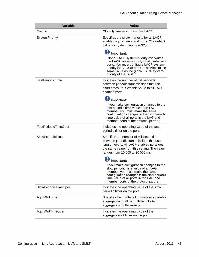
Variable ValueEnable Globally enables or disables LACP.
SystemPriority Specifies the system priority for all LACPenabled aggregators and ports. The defaultvalue for system priority is 32,768.
Important:Global LACP system-priority overwritesthe LACP system-priority of all LAGs andports. You must configure LACP system-priority for LAGs or ports on a switch to thesame value as the global LACP system-priority of that switch.
FastPeriodicTime Indicates the number of millisecondsbetween periodic transmissions that useshort timeouts. Sets this value to all LACPenabled ports.
Important:If you make configuration changes to thefast periodic time value of an LAGmember, you must make the sameconfiguration changes to the fast periodictime value of all ports in the LAG andmember ports of the protocol partner.
FastPeriodicTimeOper Indicates the operating value of the fastperiodic timer on the port.
SlowPeriodicTime Specifies the number of millisecondsbetween periodic transmissions that uselong timeouts. All LACP enabled ports getthe same value from this setting. The valueranges from 10 000 to 30 000 ms.
Important:If you make configuration changes to theslow periodic time value of an LAGmember, you must make the sameconfiguration changes to the slow periodictime value of all ports in the LAG andmember ports of the protocol partner.
SlowPeriodicTimeOper Indicates the operating value of the slowperiodic timer on the port.
AggrWaitTime Specifies the number of milliseconds to delayaggregation to allow multiple links toaggregate simultaneously.
AggrWaitTimeOper Indicates the operating value of theaggregate wait timer on the port.
LACP configuration using Device Manager
Configuration — Link Aggregation, MLT, and SMLT August 2011 45
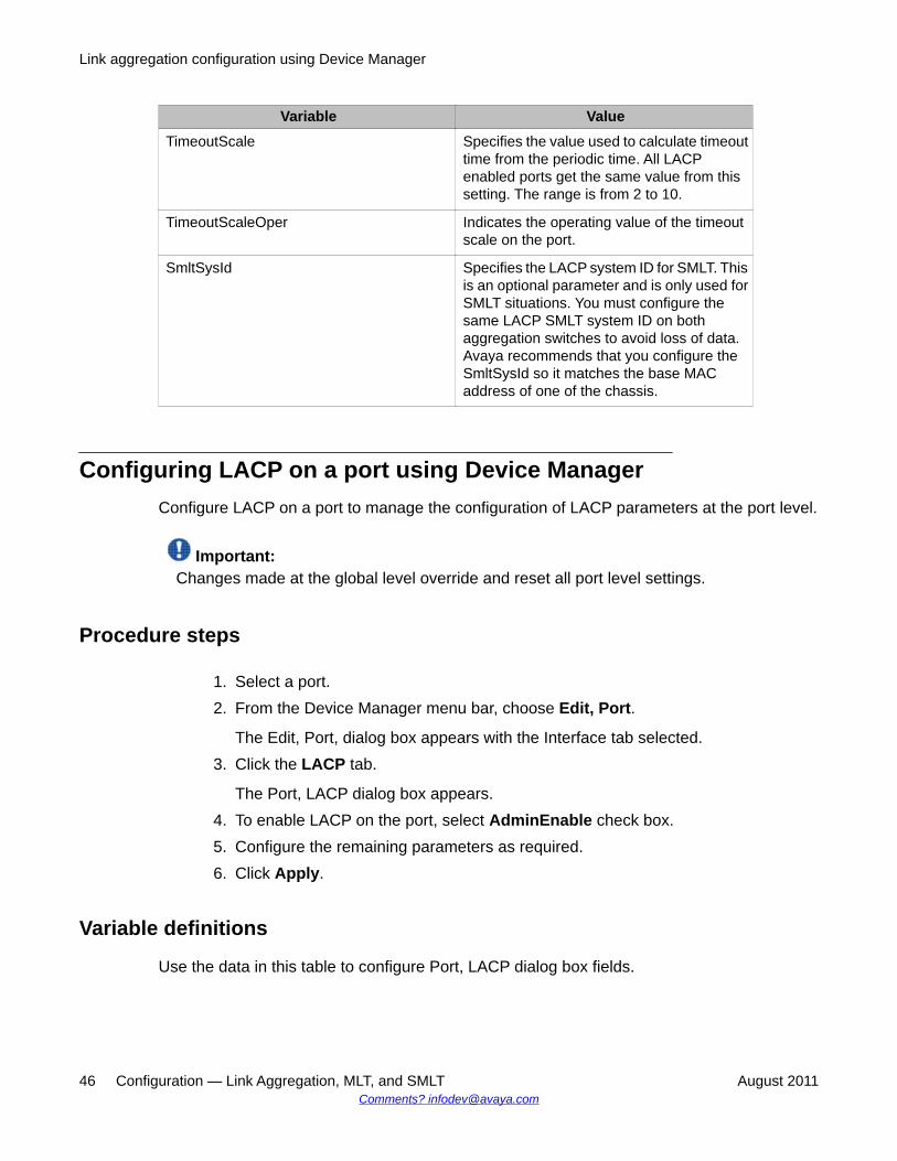
Variable ValueTimeoutScale Specifies the value used to calculate timeout
time from the periodic time. All LACPenabled ports get the same value from thissetting. The range is from 2 to 10.
TimeoutScaleOper Indicates the operating value of the timeoutscale on the port.
SmltSysId Specifies the LACP system ID for SMLT. Thisis an optional parameter and is only used forSMLT situations. You must configure thesame LACP SMLT system ID on bothaggregation switches to avoid loss of data.Avaya recommends that you configure theSmltSysId so it matches the base MACaddress of one of the chassis.
Configuring LACP on a port using Device ManagerConfigure LACP on a port to manage the configuration of LACP parameters at the port level.
Important:Changes made at the global level override and reset all port level settings.
Procedure steps
1. Select a port.2. From the Device Manager menu bar, choose Edit, Port.
The Edit, Port, dialog box appears with the Interface tab selected.3. Click the LACP tab.
The Port, LACP dialog box appears.4. To enable LACP on the port, select AdminEnable check box.5. Configure the remaining parameters as required.6. Click Apply.
Variable definitions
Use the data in this table to configure Port, LACP dialog box fields.
Link aggregation configuration using Device Manager
46 Configuration — Link Aggregation, MLT, and SMLT August 2011Comments? [email protected]
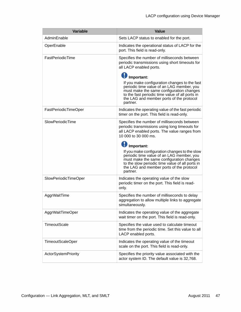
Variable ValueAdminEnable Sets LACP status to enabled for the port.
OperEnable Indicates the operational status of LACP for theport. This field is read-only.
FastPeriodicTime Specifies the number of milliseconds betweenperiodic transmissions using short timeouts forall LACP enabled ports.
Important:If you make configuration changes to the fastperiodic time value of an LAG member, youmust make the same configuration changesto the fast periodic time value of all ports inthe LAG and member ports of the protocolpartner.
FastPeriodicTimeOper Indicates the operating value of the fast periodictimer on the port. This field is read-only.
SlowPeriodicTime Specifies the number of milliseconds betweenperiodic transmissions using long timeouts forall LACP enabled ports. The value ranges from10 000 to 30 000 ms.
Important:If you make configuration changes to the slowperiodic time value of an LAG member, youmust make the same configuration changesto the slow periodic time value of all ports inthe LAG and member ports of the protocolpartner.
SlowPeriodicTimeOper Indicates the operating value of the slowperiodic timer on the port. This field is read-only.
AggrWaitTime Specifies the number of milliseconds to delayaggregation to allow multiple links to aggregatesimultaneously.
AggrWaitTimeOper Indicates the operating value of the aggregatewait timer on the port. This field is read-only.
TimeoutScale Specifies the value used to calculate timeouttime from the periodic time. Set this value to allLACP enabled ports.
TimeoutScaleOper Indicates the operating value of the timeoutscale on the port. This field is read-only.
ActorSystemPriority Specifies the priority value associated with theactor system ID. The default value is 32,768.
LACP configuration using Device Manager
Configuration — Link Aggregation, MLT, and SMLT August 2011 47
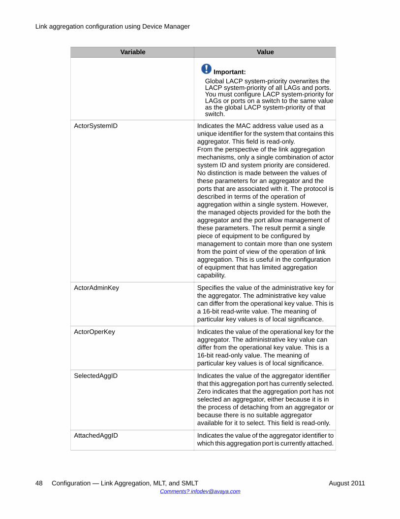
Variable Value
Important:Global LACP system-priority overwrites theLACP system-priority of all LAGs and ports.You must configure LACP system-priority forLAGs or ports on a switch to the same valueas the global LACP system-priority of thatswitch.
ActorSystemID Indicates the MAC address value used as aunique identifier for the system that contains thisaggregator. This field is read-only.From the perspective of the link aggregationmechanisms, only a single combination of actorsystem ID and system priority are considered.No distinction is made between the values ofthese parameters for an aggregator and theports that are associated with it. The protocol isdescribed in terms of the operation ofaggregation within a single system. However,the managed objects provided for the both theaggregator and the port allow management ofthese parameters. The result permit a singlepiece of equipment to be configured bymanagement to contain more than one systemfrom the point of view of the operation of linkaggregation. This is useful in the configurationof equipment that has limited aggregationcapability.
ActorAdminKey Specifies the value of the administrative key forthe aggregator. The administrative key valuecan differ from the operational key value. This isa 16-bit read-write value. The meaning ofparticular key values is of local significance.
ActorOperKey Indicates the value of the operational key for theaggregator. The administrative key value candiffer from the operational key value. This is a16-bit read-only value. The meaning ofparticular key values is of local significance.
SelectedAggID Indicates the value of the aggregator identifierthat this aggregation port has currently selected.Zero indicates that the aggregation port has notselected an aggregator, either because it is inthe process of detaching from an aggregator orbecause there is no suitable aggregatoravailable for it to select. This field is read-only.
AttachedAggID Indicates the value of the aggregator identifier towhich this aggregation port is currently attached.
Link aggregation configuration using Device Manager
48 Configuration — Link Aggregation, MLT, and SMLT August 2011Comments? [email protected]
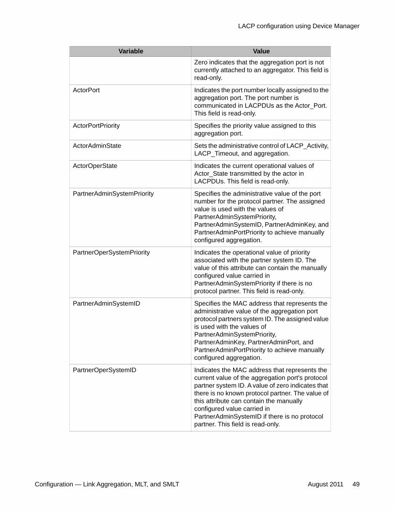
Variable ValueZero indicates that the aggregation port is notcurrently attached to an aggregator. This field isread-only.
ActorPort Indicates the port number locally assigned to theaggregation port. The port number iscommunicated in LACPDUs as the Actor_Port.This field is read-only.
ActorPortPriority Specifies the priority value assigned to thisaggregation port.
ActorAdminState Sets the administrative control of LACP_Activity,LACP_Timeout, and aggregation.
ActorOperState Indicates the current operational values ofActor_State transmitted by the actor inLACPDUs. This field is read-only.
PartnerAdminSystemPriority Specifies the administrative value of the portnumber for the protocol partner. The assignedvalue is used with the values ofPartnerAdminSystemPriority,PartnerAdminSystemID, PartnerAdminKey, andPartnerAdminPortPriority to achieve manuallyconfigured aggregation.
PartnerOperSystemPriority Indicates the operational value of priorityassociated with the partner system ID. Thevalue of this attribute can contain the manuallyconfigured value carried inPartnerAdminSystemPriority if there is noprotocol partner. This field is read-only.
PartnerAdminSystemID Specifies the MAC address that represents theadministrative value of the aggregation portprotocol partners system ID. The assigned valueis used with the values ofPartnerAdminSystemPriority,PartnerAdminKey, PartnerAdminPort, andPartnerAdminPortPriority to achieve manuallyconfigured aggregation.
PartnerOperSystemID Indicates the MAC address that represents thecurrent value of the aggregation port's protocolpartner system ID. A value of zero indicates thatthere is no known protocol partner. The value ofthis attribute can contain the manuallyconfigured value carried inPartnerAdminSystemID if there is no protocolpartner. This field is read-only.
LACP configuration using Device Manager
Configuration — Link Aggregation, MLT, and SMLT August 2011 49
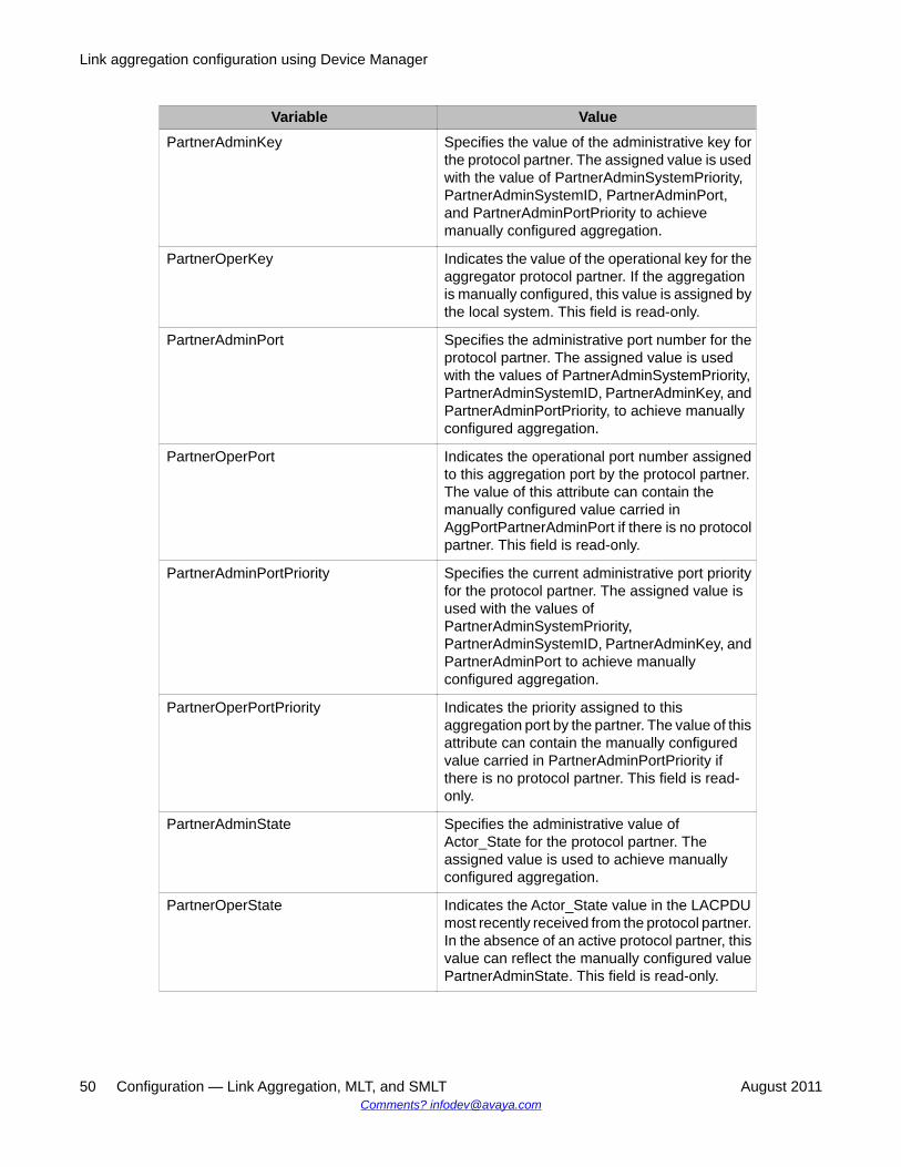
Variable ValuePartnerAdminKey Specifies the value of the administrative key for
the protocol partner. The assigned value is usedwith the value of PartnerAdminSystemPriority,PartnerAdminSystemID, PartnerAdminPort,and PartnerAdminPortPriority to achievemanually configured aggregation.
PartnerOperKey Indicates the value of the operational key for theaggregator protocol partner. If the aggregationis manually configured, this value is assigned bythe local system. This field is read-only.
PartnerAdminPort Specifies the administrative port number for theprotocol partner. The assigned value is usedwith the values of PartnerAdminSystemPriority,PartnerAdminSystemID, PartnerAdminKey, andPartnerAdminPortPriority, to achieve manuallyconfigured aggregation.
PartnerOperPort Indicates the operational port number assignedto this aggregation port by the protocol partner.The value of this attribute can contain themanually configured value carried inAggPortPartnerAdminPort if there is no protocolpartner. This field is read-only.
PartnerAdminPortPriority Specifies the current administrative port priorityfor the protocol partner. The assigned value isused with the values ofPartnerAdminSystemPriority,PartnerAdminSystemID, PartnerAdminKey, andPartnerAdminPort to achieve manuallyconfigured aggregation.
PartnerOperPortPriority Indicates the priority assigned to thisaggregation port by the partner. The value of thisattribute can contain the manually configuredvalue carried in PartnerAdminPortPriority ifthere is no protocol partner. This field is read-only.
PartnerAdminState Specifies the administrative value ofActor_State for the protocol partner. Theassigned value is used to achieve manuallyconfigured aggregation.
PartnerOperState Indicates the Actor_State value in the LACPDUmost recently received from the protocol partner.In the absence of an active protocol partner, thisvalue can reflect the manually configured valuePartnerAdminState. This field is read-only.
Link aggregation configuration using Device Manager
50 Configuration — Link Aggregation, MLT, and SMLT August 2011Comments? [email protected]
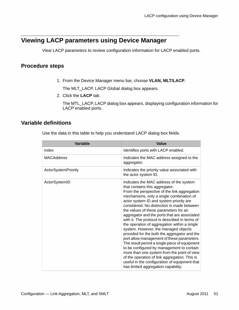
Viewing LACP parameters using Device ManagerView LACP parameters to review configuration information for LACP enabled ports.
Procedure steps
1. From the Device Manager menu bar, choose VLAN, MLT/LACP.
The MLT_LACP, LACP Global dialog box appears.2. Click the LACP tab.
The MTL_LACP, LACP dialog box appears, displaying configuration information forLACP enabled ports.
Variable definitions
Use the data in this table to help you understand LACP dialog box fields.
Variable ValueIndex Identifies ports with LACP enabled.
MACAddress Indicates the MAC address assigned to theaggregator.
ActorSystemPriority Indicates the priority value associated withthe actor system ID.
ActorSystemID Indicates the MAC address of the systemthat contains this aggregator.From the perspective of the link aggregationmechanisms, only a single combination ofactor system ID and system priority areconsidered. No distinction is made betweenthe values of these parameters for anaggregator and the ports that are associatedwith it. The protocol is described in terms ofthe operation of aggregation within a singlesystem. However, the managed objectsprovided for the both the aggregator and theport allow management of these parameters.The result permit a single piece of equipmentto be configured by management to containmore than one system from the point of viewof the operation of link aggregation. This isuseful in the configuration of equipment thathas limited aggregation capability.
LACP configuration using Device Manager
Configuration — Link Aggregation, MLT, and SMLT August 2011 51
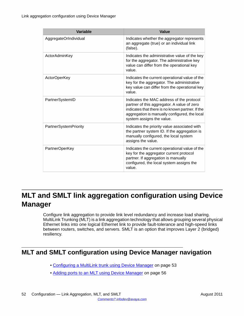
Variable ValueAggregateOrIndividual Indicates whether the aggregator represents
an aggregate (true) or an individual link(false).
ActorAdminKey Indicates the administrative value of the keyfor the aggregator. The administrative keyvalue can differ from the operational keyvalue.
ActorOperKey Indicates the current operational value of thekey for the aggregator. The administrativekey value can differ from the operational keyvalue.
PartnerSystemID Indicates the MAC address of the protocolpartner of this aggregator. A value of zeroindicates that there is no known partner. If theaggregation is manually configured, the localsystem assigns the value.
PartnerSystemPriority Indicates the priority value associated withthe partner system ID. If the aggregation ismanually configured, the local systemassigns the value.
PartnerOperKey Indicates the current operational value of thekey for the aggregator current protocolpartner. If aggregation is manuallyconfigured, the local system assigns thevalue.
MLT and SMLT link aggregation configuration using DeviceManager
Configure link aggregation to provide link level redundancy and increase load sharing.MultiLink Trunking (MLT) is a link aggregation technology that allows grouping several physicalEthernet links into one logical Ethernet link to provide fault-tolerance and high-speed linksbetween routers, switches, and servers. SMLT is an option that improves Layer 2 (bridged)resiliency.
MLT and SMLT configuration using Device Manager navigation
• Configuring a MultiLink trunk using Device Manager on page 53
• Adding ports to an MLT using Device Manager on page 56
Link aggregation configuration using Device Manager
52 Configuration — Link Aggregation, MLT, and SMLT August 2011Comments? [email protected]
• Configuring MLT-based SMLT using Device Manager on page 58
• Viewing MLT-based SMLT information using Device Manager on page 59
• Configuring a single-port SMLT using Device Manager on page 60
• Deleting a single-port SMLT using Device Manager on page 61
• Viewing single-port SMLT information using Device Manager on page 62
• Configuring rate limiting using Device Manager on page 62
• Configuring an IST MLT using Device Manager on page 63
• Removing an IST MLT using Device Manager on page 64
• Configuring a MultiLink trunk using Device Manager on page 53
• Adding ports to an MLT using Device Manager on page 56
• Configuring MLT-based SMLT using Device Manager on page 58
• Viewing MLT-based SMLT information using Device Manager on page 59
• Configuring a single-port SMLT using Device Manager on page 60
• Deleting a single-port SMLT using Device Manager on page 61
• Viewing single-port SMLT information using Device Manager on page 62
• Configuring rate limiting using Device Manager on page 62
• Configuring an IST MLT using Device Manager on page 63
• Removing an IST MLT using Device Manager on page 64
Configuring a MultiLink trunk using Device ManagerConfigure a MultiLink trunk to create and manage an MLT in your network.
Procedure steps
1. From the Device Manager menu bar, select VLAN, MLT/LACP.
The MLT_LACP, LACP Global dialog box appears.2. Click the MultiLink/LACP Trunks tab.
The MultiLink/LACP Trunks dialog box appears.3. Click Insert.
The MLT_LACP, Insert MultiLink/LACP Trunks dialog box appears.4. In the Id box, type the ID number for the MLT.
MLT and SMLT link aggregation configuration using Device Manager
Configuration — Link Aggregation, MLT, and SMLT August 2011 53
OR
Accept the default ID provided.5. In the SvlanPortType list, select a VLAN port type.6. In PortType , select a port type.7. In the Name box, type a name for the MLT.
OR
Accept the default name provided.8. In PortMembers, click the elipsis button (...).
The MltPortMembers dialog box appears.9. In the MltPortMembers dialog box, click the ports to include in the MLT.
10. Click OK.
The MltPortMembers dialog box closes. The ports you selected appear in thePortMembers field of the MLT, Insert MultiLink Trunks/LACP dialog box.
11. In VlanIds, click the ellipsis button (...).
The VlanIds dialog box appears.12. Select a VLAN ID to add to the MLT.13. Click OK.
The VlanIds dialog box closes. The VLAN type appears in the VlanIds field of theMLT, Insert MultiLink Trunks/LACP dialog box.
14. In MltType, select an MLT type.15. If you select splitMLT in step 14, enter the SMLTID number in the SmltID dialog box
that appears.
Important:The SMLT ID must be paired on each aggregation switch. The SMLT ID is theidentification number that the IST uses to determine the split MultiLink trunk towhich send information. This number is identified between the two aggregationswitches.
16. In the Multicast Distribution box, select enable to activate multicast flowdistribution.
17. Select the NtStgEnable check box to ensure that the spanning tree group is inAvaya mode.
18. In the Aggregatable box, select enable or disable.19. Click Insert.
The MLT appears in the MLT_LACP, MultiLink Trunks/LACP dialog box.
Link aggregation configuration using Device Manager
54 Configuration — Link Aggregation, MLT, and SMLT August 2011Comments? [email protected]
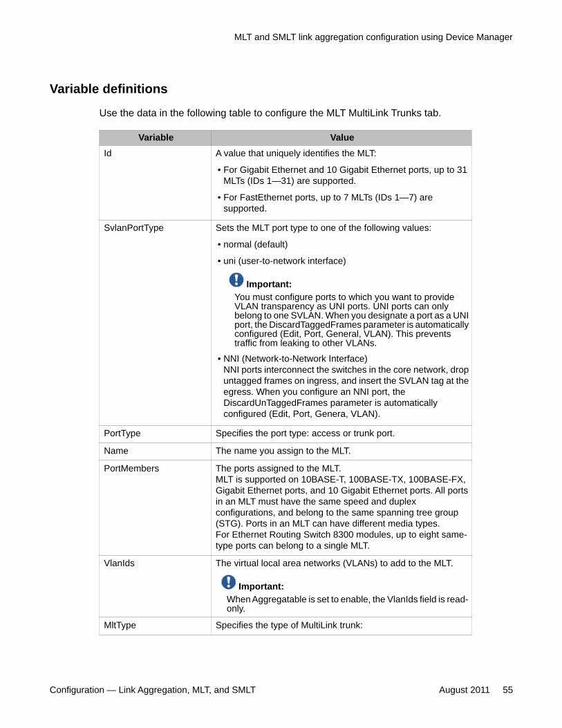
Variable definitions
Use the data in the following table to configure the MLT MultiLink Trunks tab.
Variable ValueId A value that uniquely identifies the MLT:
• For Gigabit Ethernet and 10 Gigabit Ethernet ports, up to 31MLTs (IDs 1—31) are supported.
• For FastEthernet ports, up to 7 MLTs (IDs 1—7) aresupported.
SvlanPortType Sets the MLT port type to one of the following values:
• normal (default)
• uni (user-to-network interface)
Important:You must configure ports to which you want to provideVLAN transparency as UNI ports. UNI ports can onlybelong to one SVLAN. When you designate a port as a UNIport, the DiscardTaggedFrames parameter is automaticallyconfigured (Edit, Port, General, VLAN). This preventstraffic from leaking to other VLANs.
• NNI (Network-to-Network Interface)NNI ports interconnect the switches in the core network, dropuntagged frames on ingress, and insert the SVLAN tag at theegress. When you configure an NNI port, theDiscardUnTaggedFrames parameter is automaticallyconfigured (Edit, Port, Genera, VLAN).
PortType Specifies the port type: access or trunk port.
Name The name you assign to the MLT.
PortMembers The ports assigned to the MLT.MLT is supported on 10BASE-T, 100BASE-TX, 100BASE-FX,Gigabit Ethernet ports, and 10 Gigabit Ethernet ports. All portsin an MLT must have the same speed and duplexconfigurations, and belong to the same spanning tree group(STG). Ports in an MLT can have different media types.For Ethernet Routing Switch 8300 modules, up to eight same-type ports can belong to a single MLT.
VlanIds The virtual local area networks (VLANs) to add to the MLT.
Important:When Aggregatable is set to enable, the VlanIds field is read-only.
MltType Specifies the type of MultiLink trunk:
MLT and SMLT link aggregation configuration using Device Manager
Configuration — Link Aggregation, MLT, and SMLT August 2011 55
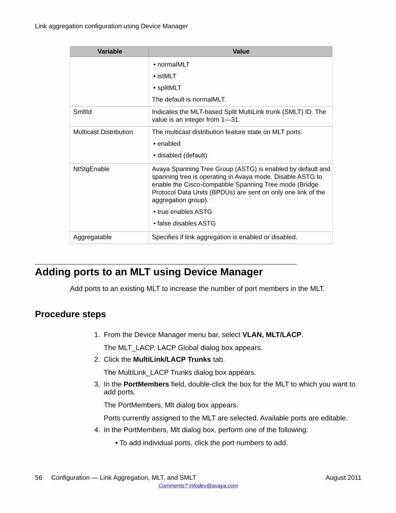
Variable Value
• normalMLT
• istMLT
• splitMLT
The default is normalMLT.
SmltId Indicates the MLT-based Split MultiLink trunk (SMLT) ID. Thevalue is an integer from 1—31.
Multicast Distribution The multicast distribution feature state on MLT ports:
• enabled
• disabled (default)
NtStgEnable Avaya Spanning Tree Group (ASTG) is enabled by default andspanning tree is operating in Avaya mode. Disable ASTG toenable the Cisco-compatible Spanning Tree mode (BridgeProtocol Data Units (BPDUs) are sent on only one link of theaggregation group).
• true enables ASTG
• false disables ASTG
Aggregatable Specifies if link aggregation is enabled or disabled.
Adding ports to an MLT using Device ManagerAdd ports to an existing MLT to increase the number of port members in the MLT.
Procedure steps
1. From the Device Manager menu bar, select VLAN, MLT/LACP.
The MLT_LACP, LACP Global dialog box appears.2. Click the MultiLink/LACP Trunks tab.
The MultiLink_LACP Trunks dialog box appears.3. In the PortMembers field, double-click the box for the MLT to which you want to
add ports.
The PortMembers, Mlt dialog box appears.
Ports currently assigned to the MLT are selected. Available ports are editable.4. In the PortMembers, Mlt dialog box, perform one of the following:
• To add individual ports, click the port numbers to add.
Link aggregation configuration using Device Manager
56 Configuration — Link Aggregation, MLT, and SMLT August 2011Comments? [email protected]
OR• To add all ports in a module, click the slot number.
OR• To add all ports, click All.
A maximum of eight ports of the same type can belong to a single MLT.5. Click OK.
The PortMembers, Mlt dialog box closes. The port numbers are added to theselected MLT on the MultiLink Trunks/LACP tab of the MLT_LACP dialog box.
6. Click Apply.
The ports are added to the MLT.7. Click Close.
The MLT_LACP dialog box closes.
Deleting ports from an MLT using Device ManagerDelete ports from an existing MLTto decrease the number of port members in the MLT.
Procedure steps
1. From the Device Manager menu bar, select VLAN, MLT/LACP.
The MLT dialog box appears with the MultiLink Trunks tab selected.2. In the PortMembers field, double-click the box for the MLT for which you want to
delete ports.
The MltPortMembers dialog box appears.
Ports currently assigned to the MLT are selected.3. In the MltPortMembers dialog box, select ports to delete from the MLT.4. Click OK.
The MltPortMembers dialog box closes. The port numbers are removed from theselected MLT on the MultiLink Trunks tab of the MLT dialog box.
5. Click Apply.
The ports are deleted from the MLT.6. Click Close.
The MLT dialog box closes.
MLT and SMLT link aggregation configuration using Device Manager
Configuration — Link Aggregation, MLT, and SMLT August 2011 57
Configuring MLT-based SMLT using Device ManagerCreate an SMLT to improve the level of Layer 2/Layer 3 resiliency by providing nodal protectionin addition to link failure protection and flexible bandwidth scaling.
Prerequisites
You must create an MLT before you can create an SMLT.
Procedure steps
1. From the Device Manager menu bar, select VLAN, MLT/LACP.
The MLT_LACP dialog box appears.2. Click the MultiLink/LACP Trunks
tab.
The MLT_LACP, MultiLink/LACP Trunks dialog box appears.3. From the displayed list of MLTs, select an available MLT to configure as an SMLT.4. Double-click the PortMembers box in the row containing the MLT.
The PortMembers dialog box appears, displaying the available ports.5. Click the ports to include in the MLT-based SMLT.
Fast Ethernet ports can be added to MLT IDs 1—7, while Gigabit ports can be addedto MLT IDs 1—31.
6. Click OK to close the PortMembers dialog box.
The ports are added to the PortMembers field of the MLT dialog box.
A maximum of eight ports can belong to a single MLT.7. Double-click the MltType field, and select splitSMLT from the list.8. Type an unused SMLT ID (1—31) in the SmltId field.
Important:The corresponding SMLTs between aggregation switches must have matchingSMLT IDs. The same ID number must be used on both sides.
9. Double-click the Aggregatable field, and select disable from the list.10. Click Apply.11. Click Close.
Link aggregation configuration using Device Manager
58 Configuration — Link Aggregation, MLT, and SMLT August 2011Comments? [email protected]
The MLT dialog box closes.
Deleting MLT-based SMLT using Device ManagerDelete an SMLT from an MLT in your network.
Procedure steps
1. From the Device Manager menu bar, select VLAN, MLT/LACP.
The MLT dialog box appears with the MultiLink Trunks tab selected.2. From the displayed list of MLTs, select an available MLT to configure as an SMLT.3. In the MltType field, double-click the splitSMLT you want to delete.4. From the list, select normalMLT.5. Click Apply.6. Click Close.
The MLT dialog box closes.
Viewing MLT-based SMLT information using Device ManagerView MLT-based SMLT information to review the configuration parameters of all MLTs on aswitch.
Procedure steps
1. From the Device Manager menu bar, select VLAN, SMLT.
The SMLT dialog box appears with the Single Port SMLT tab selected.2. Select the SMLT Info tab.
The SMLT Info tab appears and displays information for all SMLTs configured onthe switch.
Variable definitions
Use the data in the following table for reference when viewing the SMLT Info tab.
Variable ValueId Read-only field that displays the MLT ID for this SMLT.
MLT and SMLT link aggregation configuration using Device Manager
Configuration — Link Aggregation, MLT, and SMLT August 2011 59

Variable ValueSmltId Indicates the MLT-based SMLT ID (an integer from 1—32).
MltType A read-only field that displays the type of MultiLink trunk:
• normalMLT
• istMLT
• splitMLT
RunningType A read-only field that displays the MLT operational type:
• normalMLT
• istMLT
• splitMLT
Configuring a single-port SMLT using Device ManagerConfigure a single-port SMLT to use an individual port for scaling the number of split MultiLinktrunks on a switch to a maximum number of available ports.
Important:Ports that are already configured as MLT or MLT-based SMLT cannot be configured as asingle port SMLT.
Prerequisites
• You must create an MLT before you can create an SMLT.• You must remove MLT-based SMLTs and then configure the ports as single port
SMLTs.
Procedure steps
1. In the Device Manager main window, click a port.2. From the Device Manager main window, select Edit, Port.
The Port dialog box appears with the Interface tab selected.3. Select the SMLT tab.
Link aggregation configuration using Device Manager
60 Configuration — Link Aggregation, MLT, and SMLT August 2011Comments? [email protected]
Important:If information for the port appears and the MltId field is not zero, the port is alreadyconfigured as an MLT or MLT-based SMLT, so you cannot configure SMLT on theport.
4. Click Insert.
The Insert SMLT dialog box appears.5. In the SmltId box, type an unused SMLT ID number (from 1—512).6. Click Insert.
The Insert SMLT dialog box closes, and the ID is entered in the SmltId field of theSMLT tab.
7. Click Close.
The MLT dialog box closes.
Variable definitions
Use the data in the following table to configure single-port SMLT.
Field DescriptionPort The slot/port number for the port.
MltId Read-only field displaying one of the following:
• A value of 1—32 indicates that the port is part of an MLT and that,as a result, single port SMLT cannot be configured on the port.
• A value of 0 indicates that no MLT is assigned, and the port canbe configured for single port SMLT.
SmltId A read-only field indicating the SMLT ID (an integer from 1—512).You can find an unused SMLT ID by viewing the single-port SMLTIDs already configured on the switch.
Deleting a single-port SMLT using Device ManagerDelete a single port SMLT to remove the SMLT from your network.
Procedure steps
1. In the Device Manager main window, click a port.2. From the Device Manager menu bar, select Edit, Port.
MLT and SMLT link aggregation configuration using Device Manager
Configuration — Link Aggregation, MLT, and SMLT August 2011 61

3. Select the SMLT tab.
The SMLT tab displays the single port SMLT ID.4. Select the single port SMLT by selecting any field in the row.5. Click Delete.6. Click Close.
The single port SMLT configured for the port is deleted.
Viewing single-port SMLT information using Device ManagerView single-port SMLT information to review SMLT parameter information for a specific port..
Procedure steps
1. Select the port from the Device Manager main window.2. From the Device Manager menu bar, choose VLAN, SMLT.
The SMLT, Single Port SMLT dialog box appears, displaying information for theselected port.
Variable definitions
Use the data in this table to view single-port SMLT information.
Variable ValuePort Indicates the slot and port number.
SmltId The SMLT identifier for the port. Values rangefrom 1 to 512.
RunningType Identifies the SMLT running type for the port.Values are normal, ist, and split.
Configuring rate limiting using Device ManagerConfigure rate limiting to limit all packets with broadcast and multicast addresses to control theamount of user traffic.
Link aggregation configuration using Device Manager
62 Configuration — Link Aggregation, MLT, and SMLT August 2011Comments? [email protected]

Procedure steps
1. Select a port.2. From the Device Manager menu bar, choose Edit, Port.
The Edit, Port, dialog box appears with the Interface tab selected.3. Click the Rate Limiting tab.
The Port, Rate Limiting dialog box appears.4. Double-click the AllowedRate box to type a rate limiting value.5. Double-click the Enable box to select enable or disable from the list.6. Click Apply.
Variable definitions
Use the data in this table to configure Rate Limiting dialog box fields.
Variable ValueAllowedRate Specifies the rate limit to use, expressed as
a percentage. The value can be from 1 to100.
Enable Enables or disables rate limiting.
Index Defines the selected port.
TrafficType Specifies broadcast or multicast traffic.
Configuring an IST MLT using Device ManagerConfigure an InterSwitch trunking (IST) MLT to enable and manage an interconnectionbetween two aggregation switches.
Procedure steps
1. From the Device Manager menu bar, select VLAN, MLT/LACP.
The MLT_LACP dialog box appears.2. Click the MultiLink/LACP Trunks
tab.
MLT and SMLT link aggregation configuration using Device Manager
Configuration — Link Aggregation, MLT, and SMLT August 2011 63

The MLT_LACP, MultiLink/LACP Trunks dialog box appears.3. In the row containing the MLT you want to configure as an IST, double-click the
MltType box.4. Select istMLT from the list.5. Click Apply.6. Click any field in the same MLT row.
The IstMlt button is activated.7. Click the IstMlt button.
The IST MLT dialog box appears.8. In the PeerIp box, type an IP address.9. In the VlanId box, type a VLAN ID.
10. In the SessionEnable field, select the enable option button.11. Click Apply.12. Click Close.
The IST MLT dialog box closes, and the changes are applied. The IST MLT is nowconfigured.
Variable definitions
Use the data in the following table to configure the IST MLT dialog box.
Field DescriptionPeerIp The IST MLT peer IP address.
VlanId An IST VLAN ID number in the range 1—4000.
SessionEnable Enables or disables the IST functionality.
SessionStatus Indicates the status of the IST (up or down).
Removing an IST MLT using Device ManagerRemove an existing IST MLT from the switch.
Procedure steps
1. From the Device Manager menu bar, select VLAN, MLT/LACP.
Link aggregation configuration using Device Manager
64 Configuration — Link Aggregation, MLT, and SMLT August 2011Comments? [email protected]

The MLT dialog box appears with the MultiLink Trunks tab selected.2. Select the IST MLT you want to remove by clicking in any field.3. Click the IstMlt button.
The IST MLT dialog box appears.4. Select the disable option button.5. Click Apply.6. In the Device Manager confirmation window that appears, click Yes.7. Click Close.
The IST MLT dialog box closes.8. Double-click the MltType box for the IST MLT you disabled.9. From the list, select normalMLT.
10. Click Apply.11. Click Close.
The MLT dialog box closes.
VLACP configuration using Device ManagerConfigure Virtual LACP (VLACP) to implement link status control protocol at the port level.VLACP cannot interoperate with LACP.
VLACP configuration using Device Manager navigation
• Configuring VLACP globally using Device Manager on page 65
• Configuring port-based VLACP using Device Manager on page 66
Configuring VLACP globally using Device ManagerConfigure VLACP globally to enable or disable the capability of the switch to detect end-to-end failures.
Important:When you enable VLACP globally and on one or more ports on a switch, that switch isconfigured as a VLACP-end switch. A VLACP-end switch interrupts the transmission ofVLACP protocol data units (PDUs), causing VLACP to transition to a failure state.
VLACP configuration using Device Manager
Configuration — Link Aggregation, MLT, and SMLT August 2011 65
Caution:Enabling VLACP globally and on one or more ports on a switch connected between twoVLACP-end switches will cause a VLACP link failure and a loss of data.
Procedure steps
1. From the Device Manager menu bar, choose VLAN, MLT/LACP.
The MLT_LACP dialog box appears.2. Click the VLACP Global tab.
The MLT_LACP, VLACP Global dialog box appears.3. To enable VLACP globally, select the VlacpEnable check box.4. To disable VLACP globally, clear the VlacpEnable check box.5. Click Apply.
Configuring port-based VLACP using Device ManagerEnable VLACP to configure a port for virtual LACP.
Important:When you enable VLACP globally and on one or more ports on a switch, that switch isconfigured as a VLACP-end switch. A VLACP-end switch interrupts the transmission ofVLACP protocol data units (PDUs), causing VLACP to transition to a failure state.
Caution:Enabling VLACP globally and on one or more ports on a switch connected between twoVLACP-end switches will cause a VLACP link failure and a loss of data.
Important:When you configure a VLACP link across a virtual private network (VPN) or Layer 2 network,connections between VLACP peers must be point to point.
Caution:Enabling VLACP on two different interface types (MLT, VLAN, FastEthernet, orGigabitEthernet) in the same network, causes the network VLACP state to be unstable, anda loss of data can occur.
Link aggregation configuration using Device Manager
66 Configuration — Link Aggregation, MLT, and SMLT August 2011Comments? [email protected]
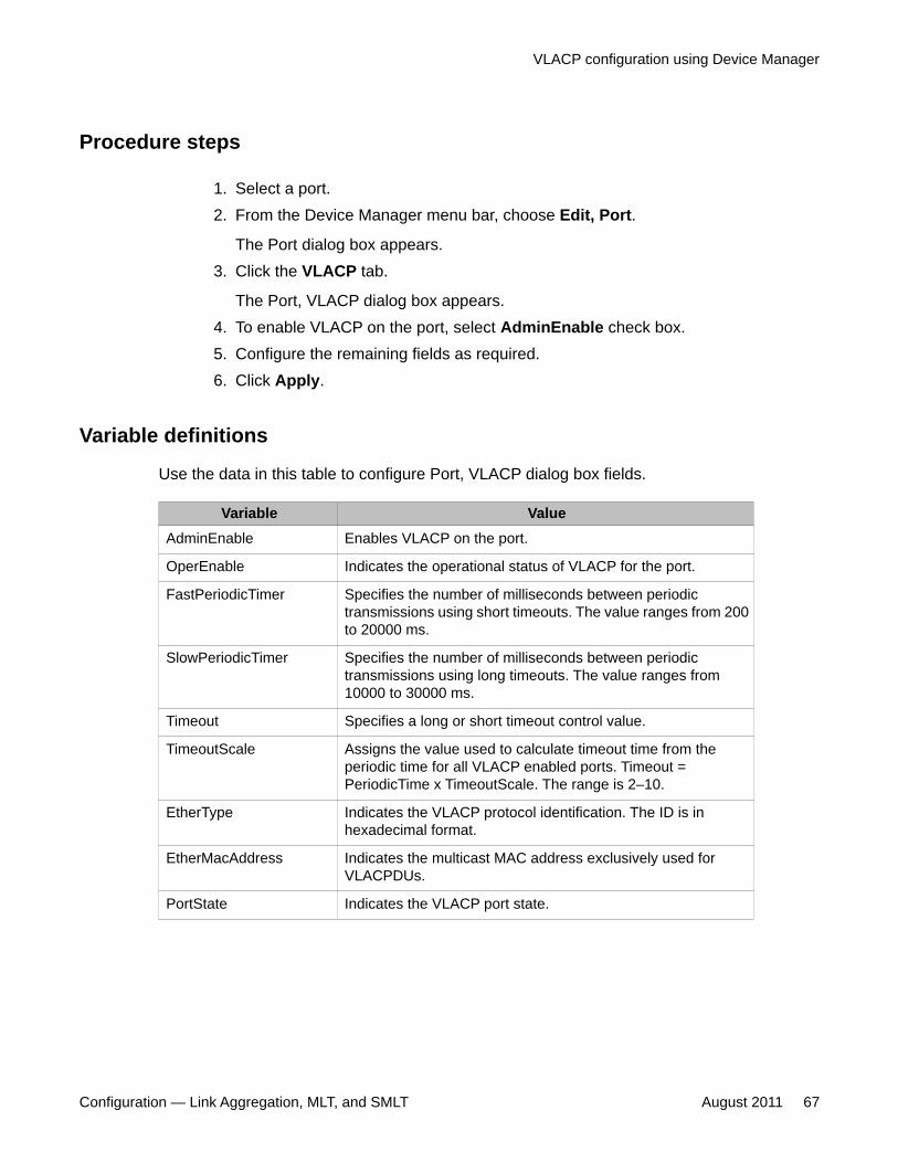
Procedure steps
1. Select a port.2. From the Device Manager menu bar, choose Edit, Port.
The Port dialog box appears.3. Click the VLACP tab.
The Port, VLACP dialog box appears.4. To enable VLACP on the port, select AdminEnable check box.5. Configure the remaining fields as required.6. Click Apply.
Variable definitions
Use the data in this table to configure Port, VLACP dialog box fields.
Variable ValueAdminEnable Enables VLACP on the port.
OperEnable Indicates the operational status of VLACP for the port.
FastPeriodicTimer Specifies the number of milliseconds between periodictransmissions using short timeouts. The value ranges from 200to 20000 ms.
SlowPeriodicTimer Specifies the number of milliseconds between periodictransmissions using long timeouts. The value ranges from10000 to 30000 ms.
Timeout Specifies a long or short timeout control value.
TimeoutScale Assigns the value used to calculate timeout time from theperiodic time for all VLACP enabled ports. Timeout =PeriodicTime x TimeoutScale. The range is 2–10.
EtherType Indicates the VLACP protocol identification. The ID is inhexadecimal format.
EtherMacAddress Indicates the multicast MAC address exclusively used forVLACPDUs.
PortState Indicates the VLACP port state.
VLACP configuration using Device Manager
Configuration — Link Aggregation, MLT, and SMLT August 2011 67

Link aggregation configuration using Device Manager
68 Configuration — Link Aggregation, MLT, and SMLT August 2011Comments? [email protected]
Chapter 5: Link aggregation configurationusing the CLI
This chapter describes how to configure and manage link aggregation using Link Aggregation ControlProtocol (LACP), Virtual Link Aggregation Control Protocol (VLACP), MultiLink trunking (MLT), SplitMultiLink trunking (SMLT), and InterSwitch trunking (IST).
All information about statistics is documented in Avaya Ethernet Routing Switch 8300 PerformanceManagement (NN46200-705).
Navigation• LACP configuration using the CLI on page 69
• MLT and SMLT link aggregation configuration using the CLI on page 77
• VLACP configuration using the CLI on page 91
LACP configuration using the CLIMultiLink Trunking (MLT) with Link Aggregation Control Protocol (LACP) manages switch portsand port memberships to form a link aggregation group (LAG). Configure LACP to allowdynamic bundling of physical ports to form a single logical channel.
LACP can be described in terms of link aggregation operations within a single system. Youcan configure a single piece of equipment so it contains more than one system (from the pointof view of the link aggregation operation).
Important:If you make a time change, restart LACP (globally or on the port) so the changes areconsistent across the link.
Important:Changes to LACP made at the global level override and reset all port level settings.
Configuration — Link Aggregation, MLT, and SMLT August 2011 69
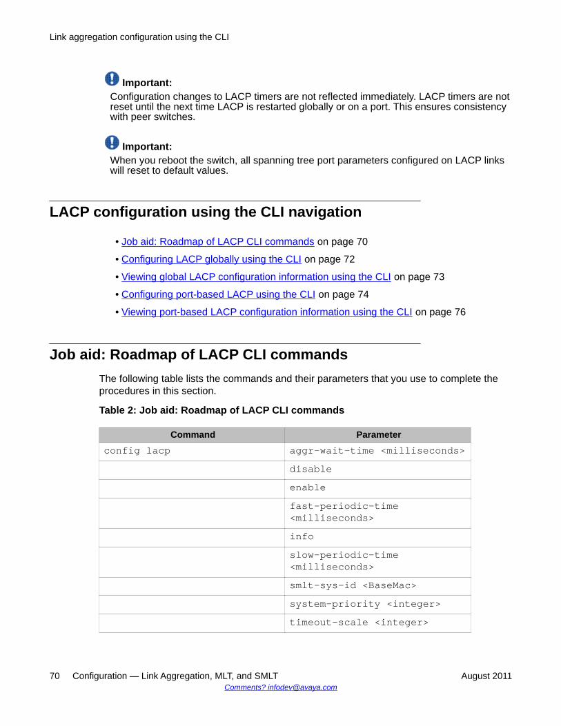
Important:Configuration changes to LACP timers are not reflected immediately. LACP timers are notreset until the next time LACP is restarted globally or on a port. This ensures consistencywith peer switches.
Important:When you reboot the switch, all spanning tree port parameters configured on LACP linkswill reset to default values.
LACP configuration using the CLI navigation
• Job aid: Roadmap of LACP CLI commands on page 70
• Configuring LACP globally using the CLI on page 72
• Viewing global LACP configuration information using the CLI on page 73
• Configuring port-based LACP using the CLI on page 74
• Viewing port-based LACP configuration information using the CLI on page 76
Job aid: Roadmap of LACP CLI commandsThe following table lists the commands and their parameters that you use to complete theprocedures in this section.
Table 2: Job aid: Roadmap of LACP CLI commands
Command Parameterconfig lacp aggr-wait-time <milliseconds>
disableenablefast-periodic-time<milliseconds>infoslow-periodic-time<milliseconds>smlt-sys-id <BaseMac>system-priority <integer>timeout-scale <integer>
Link aggregation configuration using the CLI
70 Configuration — Link Aggregation, MLT, and SMLT August 2011Comments? [email protected]
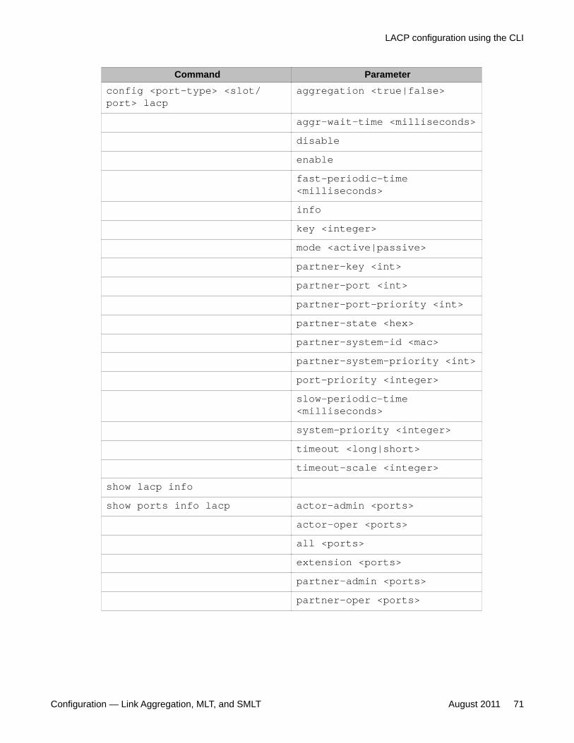
Command Parameterconfig <port-type> <slot/port> lacp
aggregation <true|false>
aggr-wait-time <milliseconds>disableenablefast-periodic-time<milliseconds>infokey <integer>mode <active|passive>partner-key <int>partner-port <int>partner-port-priority <int>partner-state <hex>partner-system-id <mac>partner-system-priority <int>port-priority <integer>slow-periodic-time<milliseconds>system-priority <integer>timeout <long|short>timeout-scale <integer>
show lacp infoshow ports info lacp actor-admin <ports>
actor-oper <ports>all <ports>extension <ports>partner-admin <ports>partner-oper <ports>
LACP configuration using the CLI
Configuration — Link Aggregation, MLT, and SMLT August 2011 71
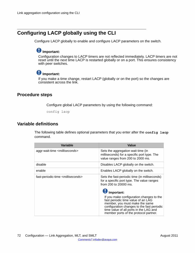
Configuring LACP globally using the CLIConfigure LACP globally to enable and configure LACP parameters on the switch.
Important:Configuration changes to LACP timers are not reflected immediately. LACP timers are notreset until the next time LACP is restarted globally or on a port. This ensures consistencywith peer switches.
Important:If you make a time change, restart LACP (globally or on the port) so the changes areconsistent across the link.
Procedure steps
Configure global LACP parameters by using the following command:
config lacp
Variable definitions
The following table defines optional parameters that you enter after the config lacpcommand.
Variable Valueaggr-wait-time <milliseconds> Sets the aggregation wait time (in
milliseconds) for a specific port type. Thevalue ranges from 200 to 2000 ms.
disable Disables LACP globally on the switch.
enable Enables LACP globally on the switch.
fast-periodic-time <milliseconds> Sets the fast-periodic time (in milliseconds)for a specific port type. The value rangesfrom 200 to 20000 ms.
Important:If you make configuration changes to thefast periodic time value of an LAGmember, you must make the sameconfiguration changes to the fast periodictime value of all ports in the LAG andmember ports of the protocol partner.
Link aggregation configuration using the CLI
72 Configuration — Link Aggregation, MLT, and SMLT August 2011Comments? [email protected]
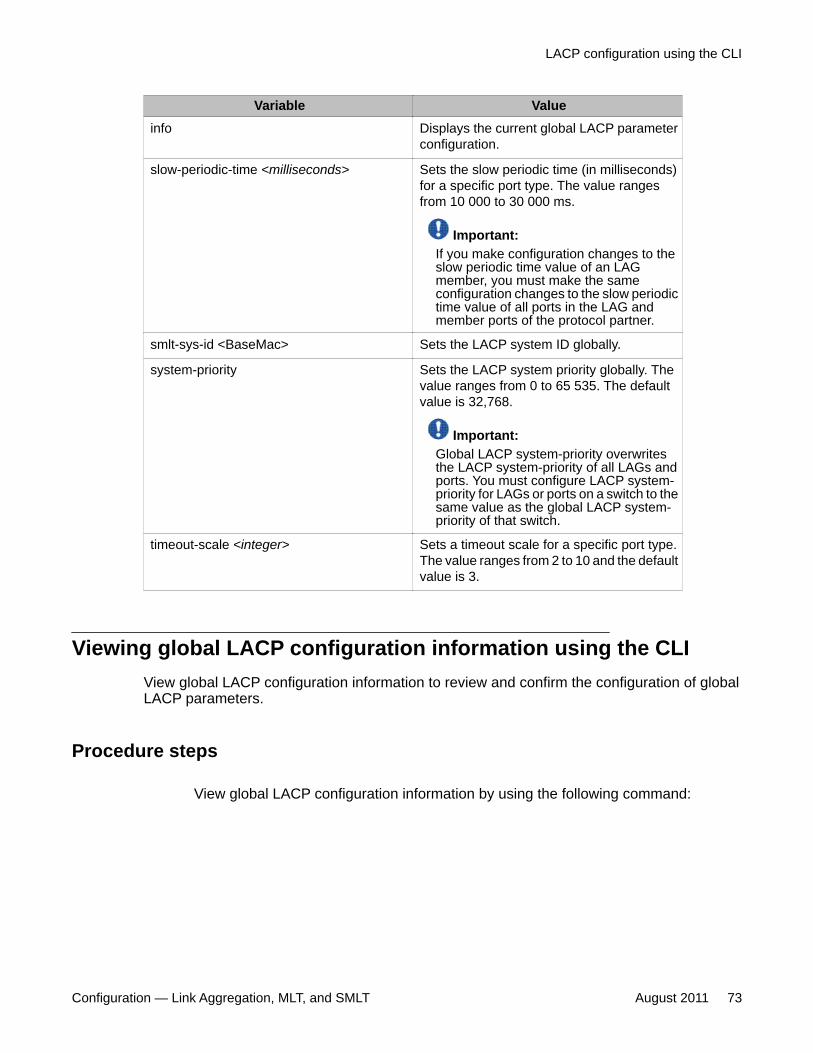
Variable Valueinfo Displays the current global LACP parameter
configuration.
slow-periodic-time <milliseconds> Sets the slow periodic time (in milliseconds)for a specific port type. The value rangesfrom 10 000 to 30 000 ms.
Important:If you make configuration changes to theslow periodic time value of an LAGmember, you must make the sameconfiguration changes to the slow periodictime value of all ports in the LAG andmember ports of the protocol partner.
smlt-sys-id <BaseMac> Sets the LACP system ID globally.
system-priority Sets the LACP system priority globally. Thevalue ranges from 0 to 65 535. The defaultvalue is 32,768.
Important:Global LACP system-priority overwritesthe LACP system-priority of all LAGs andports. You must configure LACP system-priority for LAGs or ports on a switch to thesame value as the global LACP system-priority of that switch.
timeout-scale <integer> Sets a timeout scale for a specific port type.The value ranges from 2 to 10 and the defaultvalue is 3.
Viewing global LACP configuration information using the CLIView global LACP configuration information to review and confirm the configuration of globalLACP parameters.
Procedure steps
View global LACP configuration information by using the following command:
LACP configuration using the CLI
Configuration — Link Aggregation, MLT, and SMLT August 2011 73
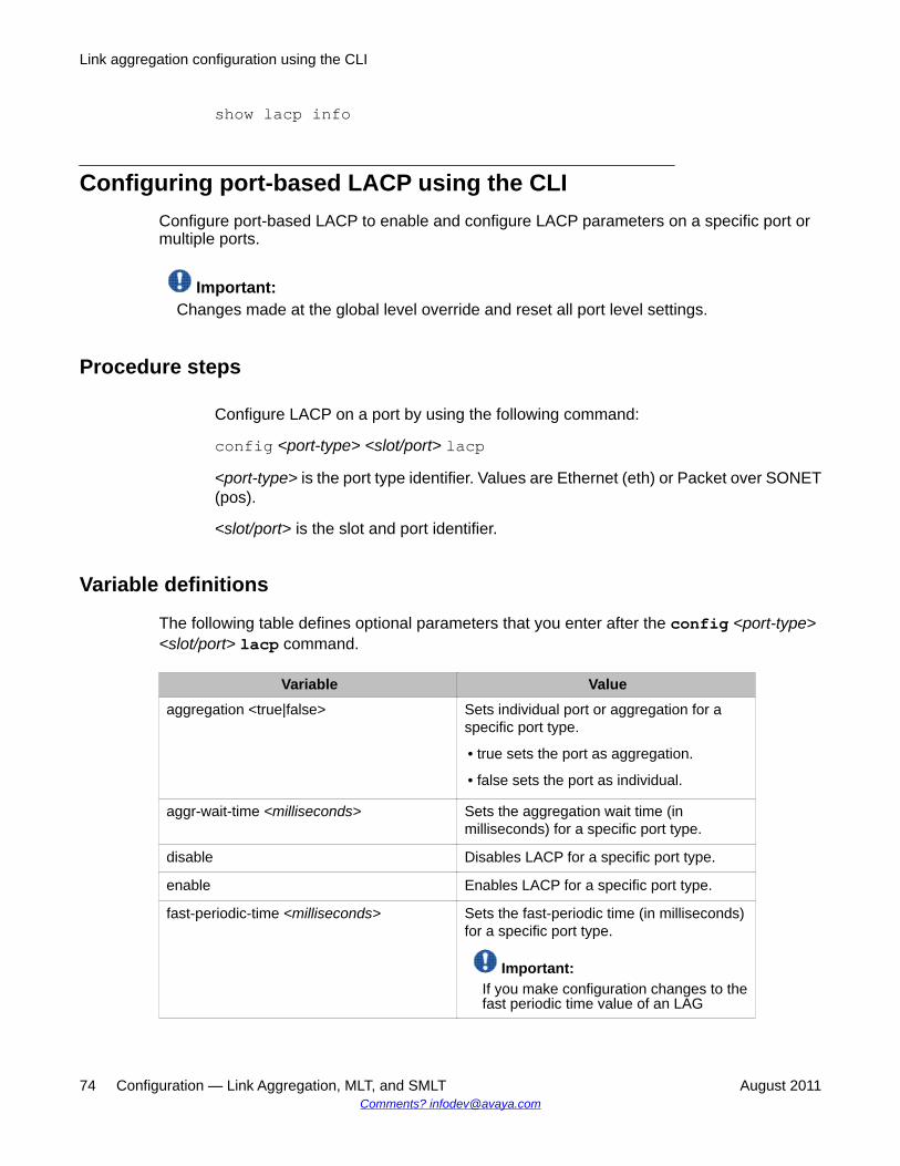
show lacp info
Configuring port-based LACP using the CLIConfigure port-based LACP to enable and configure LACP parameters on a specific port ormultiple ports.
Important:Changes made at the global level override and reset all port level settings.
Procedure steps
Configure LACP on a port by using the following command:
config <port-type> <slot/port> lacp<port-type> is the port type identifier. Values are Ethernet (eth) or Packet over SONET(pos).
<slot/port> is the slot and port identifier.
Variable definitions
The following table defines optional parameters that you enter after the config <port-type><slot/port> lacp command.
Variable Valueaggregation <true|false> Sets individual port or aggregation for a
specific port type.
• true sets the port as aggregation.
• false sets the port as individual.
aggr-wait-time <milliseconds> Sets the aggregation wait time (inmilliseconds) for a specific port type.
disable Disables LACP for a specific port type.
enable Enables LACP for a specific port type.
fast-periodic-time <milliseconds> Sets the fast-periodic time (in milliseconds)for a specific port type.
Important:If you make configuration changes to thefast periodic time value of an LAG
Link aggregation configuration using the CLI
74 Configuration — Link Aggregation, MLT, and SMLT August 2011Comments? [email protected]
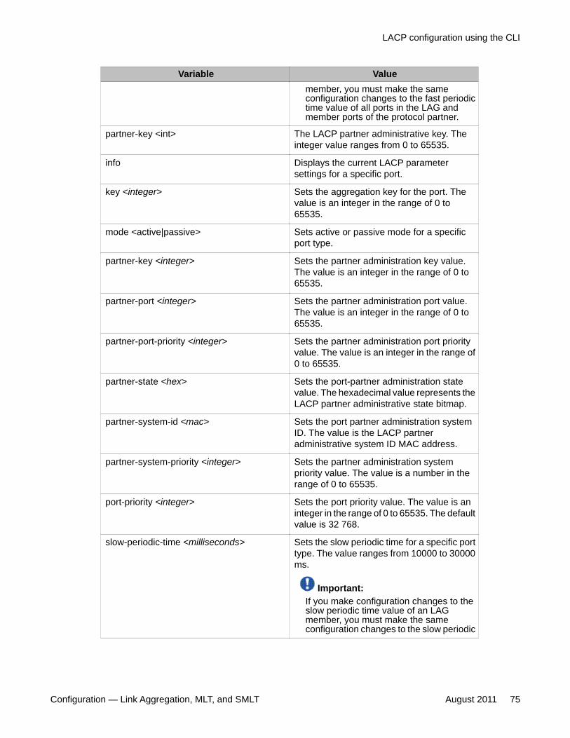
Variable Valuemember, you must make the sameconfiguration changes to the fast periodictime value of all ports in the LAG andmember ports of the protocol partner.
partner-key <int> The LACP partner administrative key. Theinteger value ranges from 0 to 65535.
info Displays the current LACP parametersettings for a specific port.
key <integer> Sets the aggregation key for the port. Thevalue is an integer in the range of 0 to65535.
mode <active|passive> Sets active or passive mode for a specificport type.
partner-key <integer> Sets the partner administration key value.The value is an integer in the range of 0 to65535.
partner-port <integer> Sets the partner administration port value.The value is an integer in the range of 0 to65535.
partner-port-priority <integer> Sets the partner administration port priorityvalue. The value is an integer in the range of0 to 65535.
partner-state <hex> Sets the port-partner administration statevalue. The hexadecimal value represents theLACP partner administrative state bitmap.
partner-system-id <mac> Sets the port partner administration systemID. The value is the LACP partneradministrative system ID MAC address.
partner-system-priority <integer> Sets the partner administration systempriority value. The value is a number in therange of 0 to 65535.
port-priority <integer> Sets the port priority value. The value is aninteger in the range of 0 to 65535. The defaultvalue is 32 768.
slow-periodic-time <milliseconds> Sets the slow periodic time for a specific porttype. The value ranges from 10000 to 30000ms.
Important:If you make configuration changes to theslow periodic time value of an LAGmember, you must make the sameconfiguration changes to the slow periodic
LACP configuration using the CLI
Configuration — Link Aggregation, MLT, and SMLT August 2011 75

Variable Valuetime value of all ports in the LAG andmember ports of the protocol partner.
system-priority <integer> Sets the lacp system priority globally. Thevalue is an integer in the range of 0 to 65535.The default value is 32,768.
Important:Global LACP system-priority overwritesthe LACP system-priority of all LAGs andports. You must configure LACP system-priority for LAGs or ports on a switch to thesame value as the global LACP system-priority of that switch.
timeout <long|short> Sets the timeout value to either long or shortfor a specific port type.
timeout-scale <integer> Sets a timeout scale for a specific port type.The value ranges from 1 to 10. The defaultvalue is 3.
Example of Configuring port-based LACP using the CLI
Procedure steps
config ethernet 1/2 lacp timeout long
Viewing port-based LACP configuration information using the CLIView port-based LACP configuration information to review and confirm the configuration ofLACP parameters for an individual port or multiple ports.
Procedure steps
View port LACP configuration information by using the following command:
show port info lacp
Variable definitions
The following table defines optional parameters that you enter after the show ports infolacp command.
Link aggregation configuration using the CLI
76 Configuration — Link Aggregation, MLT, and SMLT August 2011Comments? [email protected]
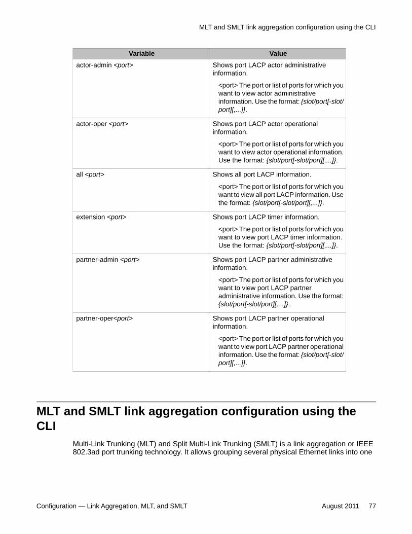
Variable Valueactor-admin <port> Shows port LACP actor administrative
information.
<port> The port or list of ports for which youwant to view actor administrativeinformation. Use the format: {slot/port[-slot/port][,...]}.
actor-oper <port> Shows port LACP actor operationalinformation.
<port> The port or list of ports for which youwant to view actor operational information.Use the format: {slot/port[-slot/port][,...]}.
all <port> Shows all port LACP information.
<port> The port or list of ports for which youwant to view all port LACP information. Usethe format: {slot/port[-slot/port][,...]}.
extension <port> Shows port LACP timer information.
<port> The port or list of ports for which youwant to view port LACP timer information.Use the format: {slot/port[-slot/port][,...]}.
partner-admin <port> Shows port LACP partner administrativeinformation.
<port> The port or list of ports for which youwant to view port LACP partneradministrative information. Use the format:{slot/port[-slot/port][,...]}.
partner-oper<port> Shows port LACP partner operationalinformation.
<port> The port or list of ports for which youwant to view port LACP partner operationalinformation. Use the format: {slot/port[-slot/port][,...]}.
MLT and SMLT link aggregation configuration using theCLI
Multi-Link Trunking (MLT) and Split Multi-Link Trunking (SMLT) is a link aggregation or IEEE802.3ad port trunking technology. It allows grouping several physical Ethernet links into one
MLT and SMLT link aggregation configuration using the CLI
Configuration — Link Aggregation, MLT, and SMLT August 2011 77
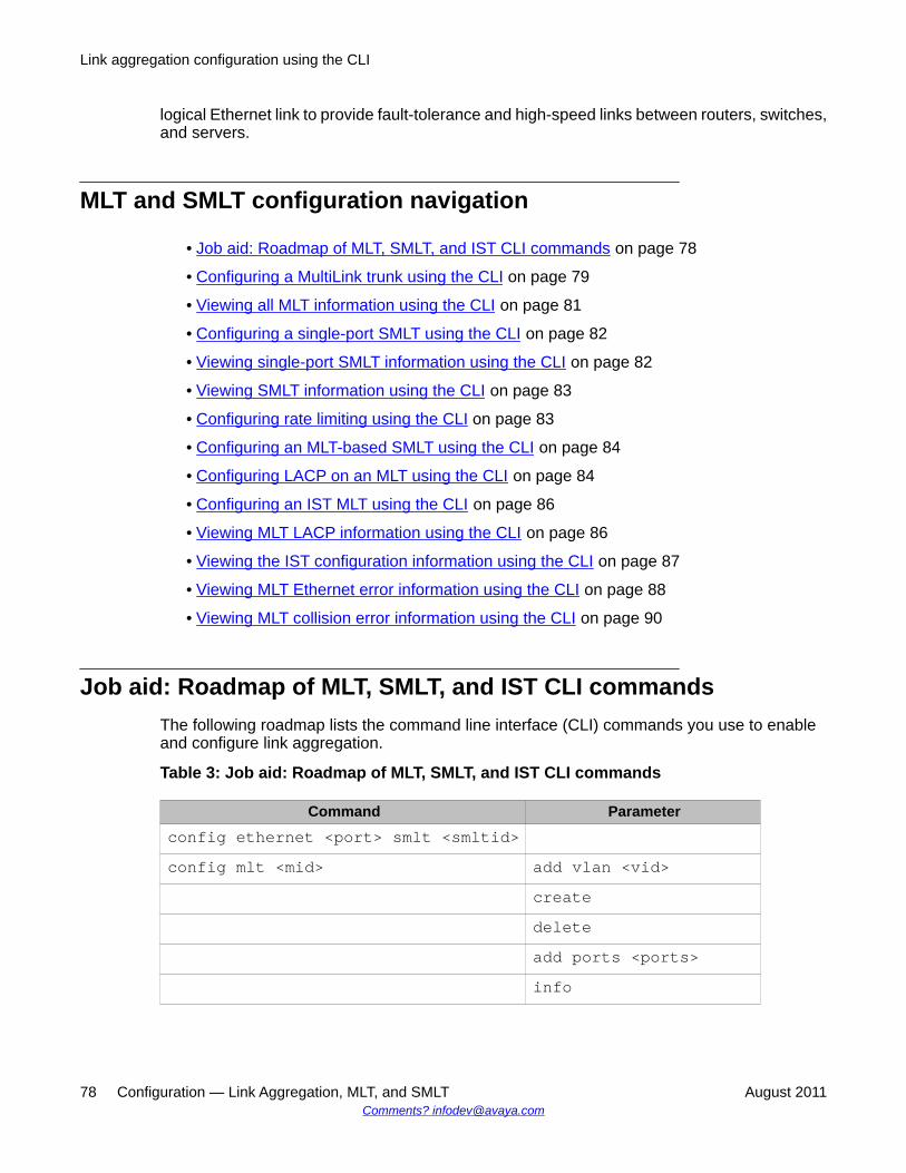
logical Ethernet link to provide fault-tolerance and high-speed links between routers, switches,and servers.
MLT and SMLT configuration navigation
• Job aid: Roadmap of MLT, SMLT, and IST CLI commands on page 78
• Configuring a MultiLink trunk using the CLI on page 79
• Viewing all MLT information using the CLI on page 81
• Configuring a single-port SMLT using the CLI on page 82
• Viewing single-port SMLT information using the CLI on page 82
• Viewing SMLT information using the CLI on page 83
• Configuring rate limiting using the CLI on page 83
• Configuring an MLT-based SMLT using the CLI on page 84
• Configuring LACP on an MLT using the CLI on page 84
• Configuring an IST MLT using the CLI on page 86
• Viewing MLT LACP information using the CLI on page 86
• Viewing the IST configuration information using the CLI on page 87
• Viewing MLT Ethernet error information using the CLI on page 88
• Viewing MLT collision error information using the CLI on page 90
Job aid: Roadmap of MLT, SMLT, and IST CLI commandsThe following roadmap lists the command line interface (CLI) commands you use to enableand configure link aggregation.
Table 3: Job aid: Roadmap of MLT, SMLT, and IST CLI commands
Command Parameterconfig ethernet <port> smlt <smltid>config mlt <mid> add vlan <vid>
createdeleteadd ports <ports>info
Link aggregation configuration using the CLI
78 Configuration — Link Aggregation, MLT, and SMLT August 2011Comments? [email protected]
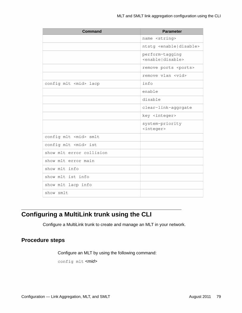
Command Parametername <string>ntstg <enable|disable>perform-tagging<enable|disable>remove ports <ports>remove vlan <vid>
config mlt <mid> lacp infoenabledisableclear-link-aggrgatekey <integer>system-priority<integer>
config mlt <mid> smltconfig mlt <mid> istshow mlt error collisionshow mlt error mainshow mlt infoshow mlt ist infoshow mlt lacp infoshow smlt
Configuring a MultiLink trunk using the CLIConfigure a MultiLink trunk to create and manage an MLT in your network.
Procedure steps
Configure an MLT by using the following command:
config mlt <mid>
MLT and SMLT link aggregation configuration using the CLI
Configuration — Link Aggregation, MLT, and SMLT August 2011 79
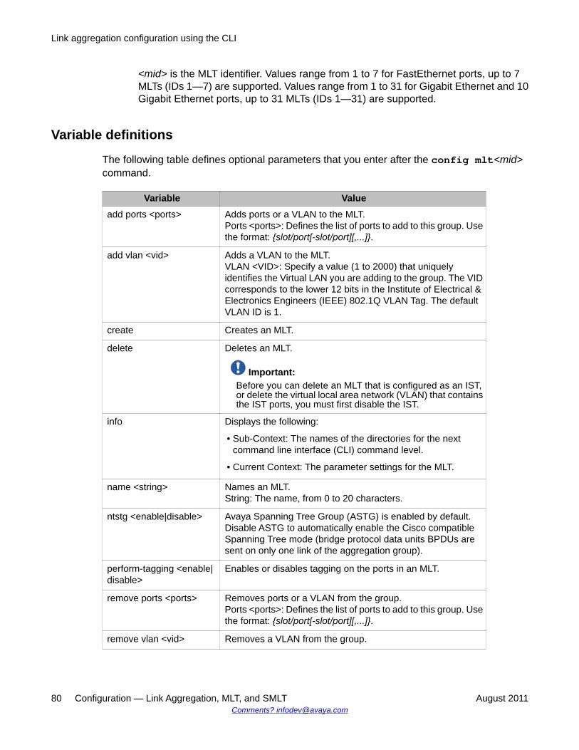
<mid> is the MLT identifier. Values range from 1 to 7 for FastEthernet ports, up to 7MLTs (IDs 1—7) are supported. Values range from 1 to 31 for Gigabit Ethernet and 10Gigabit Ethernet ports, up to 31 MLTs (IDs 1—31) are supported.
Variable definitions
The following table defines optional parameters that you enter after the config mlt<mid>command.
Variable Valueadd ports <ports> Adds ports or a VLAN to the MLT.
Ports <ports>: Defines the list of ports to add to this group. Usethe format: {slot/port[-slot/port][,...]}.
add vlan <vid> Adds a VLAN to the MLT.VLAN <VID>: Specify a value (1 to 2000) that uniquelyidentifies the Virtual LAN you are adding to the group. The VIDcorresponds to the lower 12 bits in the Institute of Electrical &Electronics Engineers (IEEE) 802.1Q VLAN Tag. The defaultVLAN ID is 1.
create Creates an MLT.
delete Deletes an MLT.
Important:Before you can delete an MLT that is configured as an IST,or delete the virtual local area network (VLAN) that containsthe IST ports, you must first disable the IST.
info Displays the following:
• Sub-Context: The names of the directories for the nextcommand line interface (CLI) command level.
• Current Context: The parameter settings for the MLT.
name <string> Names an MLT.String: The name, from 0 to 20 characters.
ntstg <enable|disable> Avaya Spanning Tree Group (ASTG) is enabled by default.Disable ASTG to automatically enable the Cisco compatibleSpanning Tree mode (bridge protocol data units BPDUs aresent on only one link of the aggregation group).
perform-tagging <enable|disable>
Enables or disables tagging on the ports in an MLT.
remove ports <ports> Removes ports or a VLAN from the group.Ports <ports>: Defines the list of ports to add to this group. Usethe format: {slot/port[-slot/port][,...]}.
remove vlan <vid> Removes a VLAN from the group.
Link aggregation configuration using the CLI
80 Configuration — Link Aggregation, MLT, and SMLT August 2011Comments? [email protected]

Variable ValueVLAN <VID>: Specify a value (1 to 2000) that uniquelyidentifies the Virtual LAN you are adding to the group. The VIDcorresponds to the lower 12 bits in the IEEE 802.1Q VLAN Tag.The default VLAN ID is 1.
Viewing all MLT information using the CLIYou can view information about all MLTs configured on a switch.
Procedure steps
View all MLT configuration information by using the following command:
show mlt info
Job aid: show mlt info output
The following table displays field descriptions for the show mlt info command.
Table 4: Job aid: show mlt info output
Field DescriptionMLTID Indicates the MultiLink trunk ID number.
DESIGNATED PORT Indicates the designated port for the MultiLink trunk.
IFINDEX Indicates the interface index number.
NAME Indicates the name of this MultiLink trunk.
LACP ADMIN Indicates the administrative status of LACP on the MultiLinktrunk.
LACP OPER Indicates the operational status of LACP on the MultiLinktrunk.
PORT TYPE Indicates the type of MultiLink trunk port: access or trunk.
VLAN IDS Indicates the number of VLANS on the MultiLink trunk.
MLT ADMIN Indicates the status of MLT.
MLT CURRENT Indicates the operational status of MLT.
PORT MEMBERS Indicates the set of ports that are members of this MultiLinktrunk.
MLT and SMLT link aggregation configuration using the CLI
Configuration — Link Aggregation, MLT, and SMLT August 2011 81
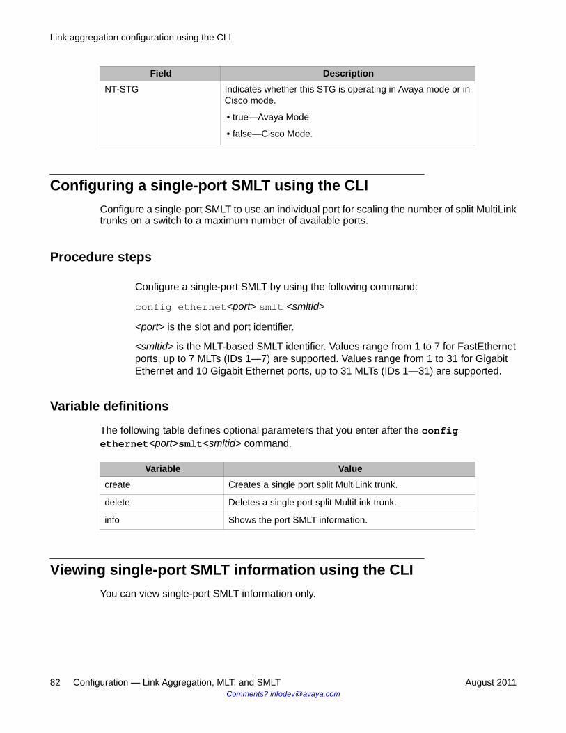
Field DescriptionNT-STG Indicates whether this STG is operating in Avaya mode or in
Cisco mode.
• true—Avaya Mode
• false—Cisco Mode.
Configuring a single-port SMLT using the CLIConfigure a single-port SMLT to use an individual port for scaling the number of split MultiLinktrunks on a switch to a maximum number of available ports.
Procedure steps
Configure a single-port SMLT by using the following command:
config ethernet<port> smlt <smltid>
<port> is the slot and port identifier.
<smltid> is the MLT-based SMLT identifier. Values range from 1 to 7 for FastEthernetports, up to 7 MLTs (IDs 1—7) are supported. Values range from 1 to 31 for GigabitEthernet and 10 Gigabit Ethernet ports, up to 31 MLTs (IDs 1—31) are supported.
Variable definitions
The following table defines optional parameters that you enter after the configethernet<port>smlt<smltid> command.
Variable Valuecreate Creates a single port split MultiLink trunk.
delete Deletes a single port split MultiLink trunk.
info Shows the port SMLT information.
Viewing single-port SMLT information using the CLIYou can view single-port SMLT information only.
Link aggregation configuration using the CLI
82 Configuration — Link Aggregation, MLT, and SMLT August 2011Comments? [email protected]
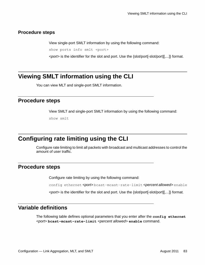
Procedure steps
View single-port SMLT information by using the following command:
show ports info smlt <port><port> is the identifier for the slot and port. Use the {slot/port[-slot/port][,...]} format.
Viewing SMLT information using the CLIYou can view MLT and single-port SMLT information.
Procedure steps
View SMLT and single-port SMLT information by using the following command:
show smlt
Configuring rate limiting using the CLIConfigure rate limiting to limit all packets with broadcast and multicast addresses to control theamount of user traffic.
Procedure steps
Configure rate limiting by using the following command:
config ethernet <port> bcast-mcast-rate-limit <percent allowed> enable<port> is the identifier for the slot and port. Use the {slot/port[-slot/port][,...]} format.
Variable definitionsThe following table defines optional parameters that you enter after the config ethernet<port> bcast-mcast-rate-limit <percent allowed> enable command.
Viewing SMLT information using the CLI
Configuration — Link Aggregation, MLT, and SMLT August 2011 83
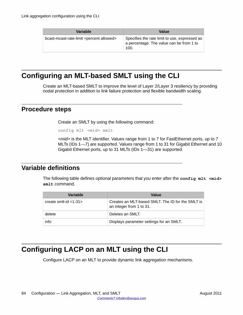
Variable Valuebcast-mcast-rate-limit <percent allowed> Specifies the rate limit to use, expressed as
a percentage. The value can be from 1 to100.
Configuring an MLT-based SMLT using the CLICreate an MLT-based SMLT to improve the level of Layer 2/Layer 3 resiliency by providingnodal protection in addition to link failure protection and flexible bandwidth scaling.
Procedure steps
Create an SMLT by using the following command:
config mlt <mid> smlt<mid> is the MLT identifier. Values range from 1 to 7 for FastEthernet ports, up to 7MLTs (IDs 1—7) are supported. Values range from 1 to 31 for Gigabit Ethernet and 10Gigabit Ethernet ports, up to 31 MLTs (IDs 1—31) are supported.
Variable definitionsThe following table defines optional parameters that you enter after the config mlt <mid>smlt command.
Variable Valuecreate smlt-id <1-31> Creates an MLT-based SMLT. The ID for the SMLT is
an integer from 1 to 31.
delete Deletes an SMLT.
info Displays parameter settings for an SMLT.
Configuring LACP on an MLT using the CLIConfigure LACP on an MLT to provide dynamic link aggregation mechanisms.
Link aggregation configuration using the CLI
84 Configuration — Link Aggregation, MLT, and SMLT August 2011Comments? [email protected]
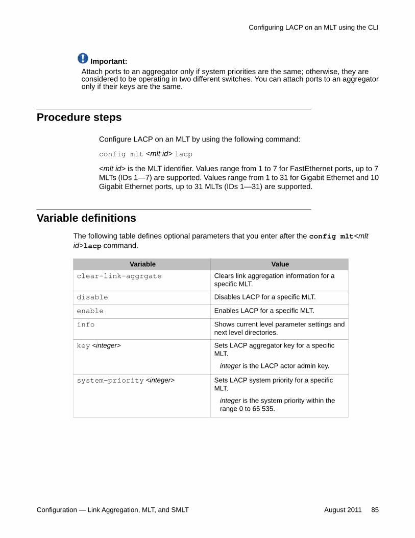
Important:Attach ports to an aggregator only if system priorities are the same; otherwise, they areconsidered to be operating in two different switches. You can attach ports to an aggregatoronly if their keys are the same.
Procedure steps
Configure LACP on an MLT by using the following command:
config mlt <mlt id> lacp<mlt id> is the MLT identifier. Values range from 1 to 7 for FastEthernet ports, up to 7MLTs (IDs 1—7) are supported. Values range from 1 to 31 for Gigabit Ethernet and 10Gigabit Ethernet ports, up to 31 MLTs (IDs 1—31) are supported.
Variable definitionsThe following table defines optional parameters that you enter after the config mlt<mltid>lacp command.
Variable Valueclear-link-aggrgate Clears link aggregation information for a
specific MLT.
disable Disables LACP for a specific MLT.
enable Enables LACP for a specific MLT.
info Shows current level parameter settings andnext level directories.
key <integer> Sets LACP aggregator key for a specificMLT.
integer is the LACP actor admin key.
system-priority <integer> Sets LACP system priority for a specificMLT.
integer is the system priority within therange 0 to 65 535.
Configuring LACP on an MLT using the CLI
Configuration — Link Aggregation, MLT, and SMLT August 2011 85
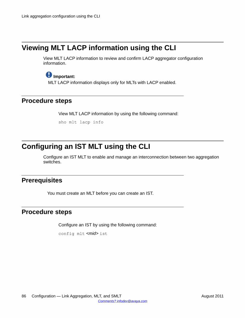
Viewing MLT LACP information using the CLIView MLT LACP information to review and confirm LACP aggregator configurationinformation.
Important:MLT LACP information displays only for MLTs with LACP enabled.
Procedure steps
View MLT LACP information by using the following command:
sho mlt lacp info
Configuring an IST MLT using the CLIConfigure an IST MLT to enable and manage an interconnection between two aggregationswitches.
Prerequisites
You must create an MLT before you can create an IST.
Procedure steps
Configure an IST by using the following command:
config mlt <mid> ist
Link aggregation configuration using the CLI
86 Configuration — Link Aggregation, MLT, and SMLT August 2011Comments? [email protected]
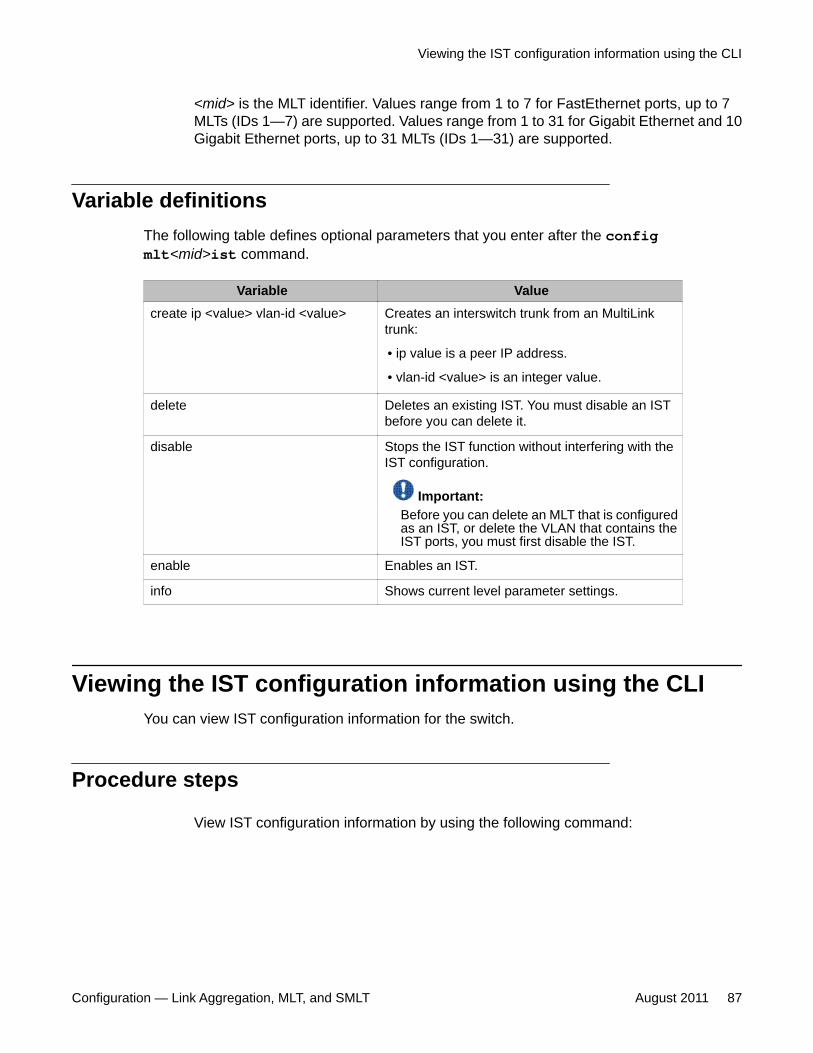
<mid> is the MLT identifier. Values range from 1 to 7 for FastEthernet ports, up to 7MLTs (IDs 1—7) are supported. Values range from 1 to 31 for Gigabit Ethernet and 10Gigabit Ethernet ports, up to 31 MLTs (IDs 1—31) are supported.
Variable definitionsThe following table defines optional parameters that you enter after the configmlt<mid>ist command.
Variable Valuecreate ip <value> vlan-id <value> Creates an interswitch trunk from an MultiLink
trunk:
• ip value is a peer IP address.
• vlan-id <value> is an integer value.
delete Deletes an existing IST. You must disable an ISTbefore you can delete it.
disable Stops the IST function without interfering with theIST configuration.
Important:Before you can delete an MLT that is configuredas an IST, or delete the VLAN that contains theIST ports, you must first disable the IST.
enable Enables an IST.
info Shows current level parameter settings.
Viewing the IST configuration information using the CLIYou can view IST configuration information for the switch.
Procedure steps
View IST configuration information by using the following command:
Viewing the IST configuration information using the CLI
Configuration — Link Aggregation, MLT, and SMLT August 2011 87
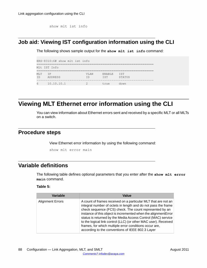
show mlt ist info
Job aid: Viewing IST configuration information using the CLIThe following shows sample output for the show mlt ist info command:
ERS-8310:6# show mlt ist info================================================================Mlt IST Info================================================================MLT IP VLAN ENABLE ISTID ADDRESS ID IST STATUS ----------------------------------------------------------------6 10.10.10.1 2 true down
Viewing MLT Ethernet error information using the CLIYou can view information about Ethernet errors sent and received by a specific MLT or all MLTson a switch.
Procedure steps
View Ethernet error information by using the following command:
show mlt error main
Variable definitionsThe following table defines optional parameters that you enter after the show mlt errormain command.
Table 5:
Variable ValueAlignment Errors A count of frames received on a particular MLT that are not an
integral number of octets in length and do not pass the framecheck sequence (FCS) check. The count represented by aninstance of this object is incremented when the alignmentErrorstatus is returned by the Media Access Control (MAC) serviceto the logical link control (LLC) (or other MAC user). Receivedframes, for which multiple error conditions occur are,according to the conventions of IEEE 802.3 Layer
Link aggregation configuration using the CLI
88 Configuration — Link Aggregation, MLT, and SMLT August 2011Comments? [email protected]
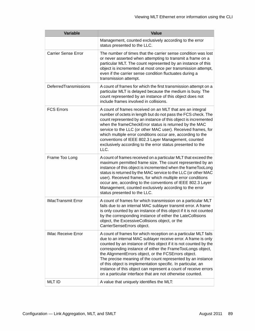
Variable ValueManagement, counted exclusively according to the errorstatus presented to the LLC.
Carrier Sense Error The number of times that the carrier sense condition was lostor never asserted when attempting to transmit a frame on aparticular MLT. The count represented by an instance of thisobject is incremented at most once per transmission attempt,even if the carrier sense condition fluctuates during atransmission attempt.
DeferredTransmissions A count of frames for which the first transmission attempt on aparticular MLT is delayed because the medium is busy. Thecount represented by an instance of this object does notinclude frames involved in collisions.
FCS Errors A count of frames received on an MLT that are an integralnumber of octets in length but do not pass the FCS check. Thecount represented by an instance of this object is incrementedwhen the frameCheckError status is returned by the MACservice to the LLC (or other MAC user). Received frames, forwhich multiple error conditions occur are, according to theconventions of IEEE 802.3 Layer Management, countedexclusively according to the error status presented to theLLC.
Frame Too Long A count of frames received on a particular MLT that exceed themaximum permitted frame size. The count represented by aninstance of this object is incremented when the frameTooLongstatus is returned by the MAC service to the LLC (or other MACuser). Received frames, for which multiple error conditionsoccur are, according to the conventions of IEEE 802.3 LayerManagement, counted exclusively according to the errorstatus presented to the LLC.
IMacTransmit Error A count of frames for which transmission on a particular MLTfails due to an internal MAC sublayer transmit error. A frameis only counted by an instance of this object if it is not countedby the corresponding instance of either the LateCollisionsobject, the ExcessiveCollisions object, or theCarrierSenseErrors object.
IMac Receive Error A count of frames for which reception on a particular MLT failsdue to an internal MAC sublayer receive error. A frame is onlycounted by an instance of this object if it is not counted by thecorresponding instance of either the FrameTooLongs object,the AlignmentErrors object, or the FCSErrors object.The precise meaning of the count represented by an instanceof this object is implementation specific. In particular, aninstance of this object can represent a count of receive errorson a particular interface that are not otherwise counted.
MLT ID A value that uniquely identifies the MLT:
Viewing MLT Ethernet error information using the CLI
Configuration — Link Aggregation, MLT, and SMLT August 2011 89
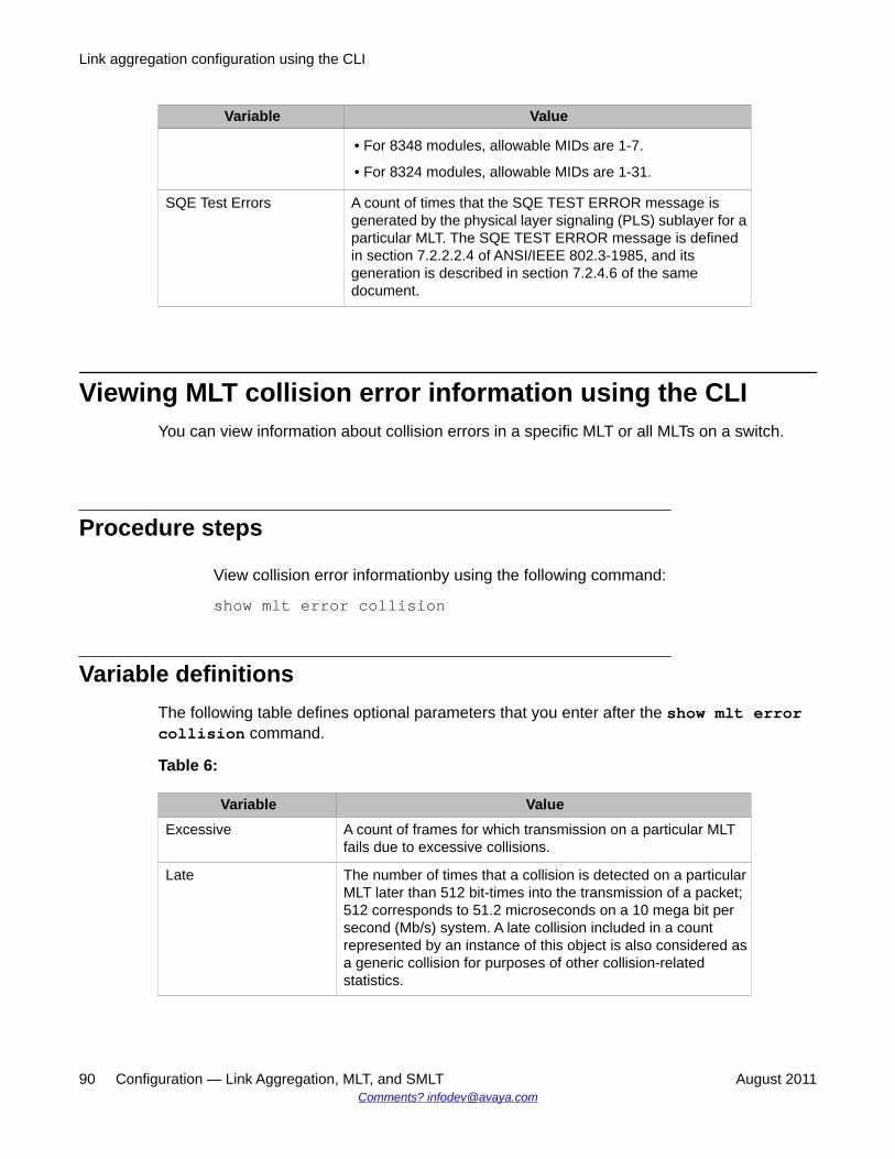
Variable Value
• For 8348 modules, allowable MIDs are 1-7.
• For 8324 modules, allowable MIDs are 1-31.
SQE Test Errors A count of times that the SQE TEST ERROR message isgenerated by the physical layer signaling (PLS) sublayer for aparticular MLT. The SQE TEST ERROR message is definedin section 7.2.2.2.4 of ANSI/IEEE 802.3-1985, and itsgeneration is described in section 7.2.4.6 of the samedocument.
Viewing MLT collision error information using the CLIYou can view information about collision errors in a specific MLT or all MLTs on a switch.
Procedure steps
View collision error informationby using the following command:
show mlt error collision
Variable definitionsThe following table defines optional parameters that you enter after the show mlt errorcollision command.
Table 6:
Variable ValueExcessive A count of frames for which transmission on a particular MLT
fails due to excessive collisions.
Late The number of times that a collision is detected on a particularMLT later than 512 bit-times into the transmission of a packet;512 corresponds to 51.2 microseconds on a 10 mega bit persecond (Mb/s) system. A late collision included in a countrepresented by an instance of this object is also considered asa generic collision for purposes of other collision-relatedstatistics.
Link aggregation configuration using the CLI
90 Configuration — Link Aggregation, MLT, and SMLT August 2011Comments? [email protected]
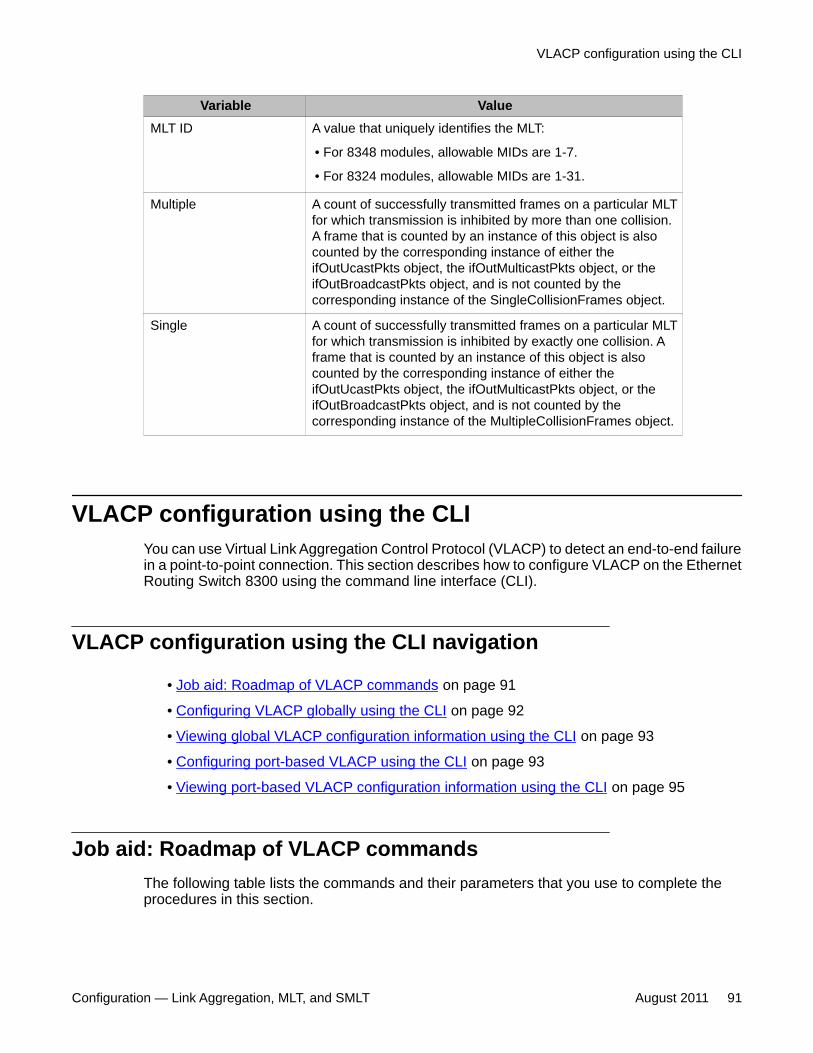
Variable ValueMLT ID A value that uniquely identifies the MLT:
• For 8348 modules, allowable MIDs are 1-7.
• For 8324 modules, allowable MIDs are 1-31.
Multiple A count of successfully transmitted frames on a particular MLTfor which transmission is inhibited by more than one collision.A frame that is counted by an instance of this object is alsocounted by the corresponding instance of either theifOutUcastPkts object, the ifOutMulticastPkts object, or theifOutBroadcastPkts object, and is not counted by thecorresponding instance of the SingleCollisionFrames object.
Single A count of successfully transmitted frames on a particular MLTfor which transmission is inhibited by exactly one collision. Aframe that is counted by an instance of this object is alsocounted by the corresponding instance of either theifOutUcastPkts object, the ifOutMulticastPkts object, or theifOutBroadcastPkts object, and is not counted by thecorresponding instance of the MultipleCollisionFrames object.
VLACP configuration using the CLIYou can use Virtual Link Aggregation Control Protocol (VLACP) to detect an end-to-end failurein a point-to-point connection. This section describes how to configure VLACP on the EthernetRouting Switch 8300 using the command line interface (CLI).
VLACP configuration using the CLI navigation
• Job aid: Roadmap of VLACP commands on page 91
• Configuring VLACP globally using the CLI on page 92
• Viewing global VLACP configuration information using the CLI on page 93
• Configuring port-based VLACP using the CLI on page 93
• Viewing port-based VLACP configuration information using the CLI on page 95
Job aid: Roadmap of VLACP commandsThe following table lists the commands and their parameters that you use to complete theprocedures in this section.
VLACP configuration using the CLI
Configuration — Link Aggregation, MLT, and SMLT August 2011 91
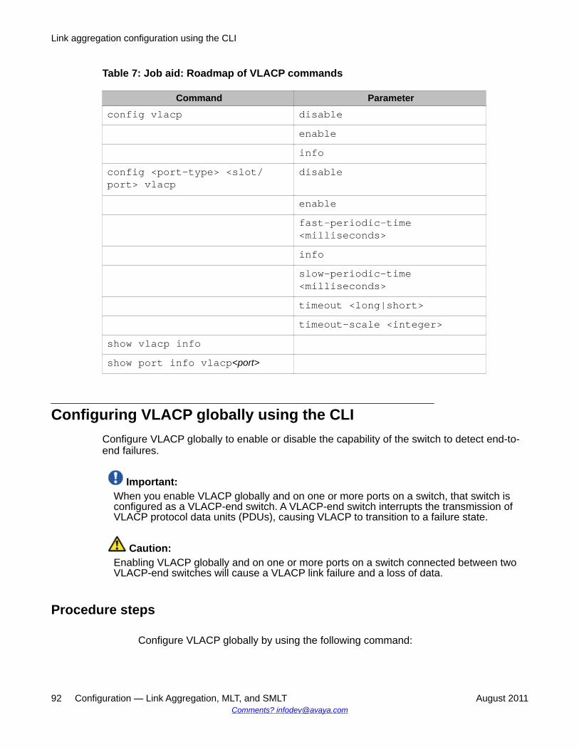
Table 7: Job aid: Roadmap of VLACP commands
Command Parameterconfig vlacp disable
enableinfo
config <port-type> <slot/port> vlacp
disable
enablefast-periodic-time<milliseconds>infoslow-periodic-time<milliseconds>timeout <long|short>timeout-scale <integer>
show vlacp infoshow port info vlacp<port>
Configuring VLACP globally using the CLIConfigure VLACP globally to enable or disable the capability of the switch to detect end-to-end failures.
Important:When you enable VLACP globally and on one or more ports on a switch, that switch isconfigured as a VLACP-end switch. A VLACP-end switch interrupts the transmission ofVLACP protocol data units (PDUs), causing VLACP to transition to a failure state.
Caution:Enabling VLACP globally and on one or more ports on a switch connected between twoVLACP-end switches will cause a VLACP link failure and a loss of data.
Procedure steps
Configure VLACP globally by using the following command:
Link aggregation configuration using the CLI
92 Configuration — Link Aggregation, MLT, and SMLT August 2011Comments? [email protected]
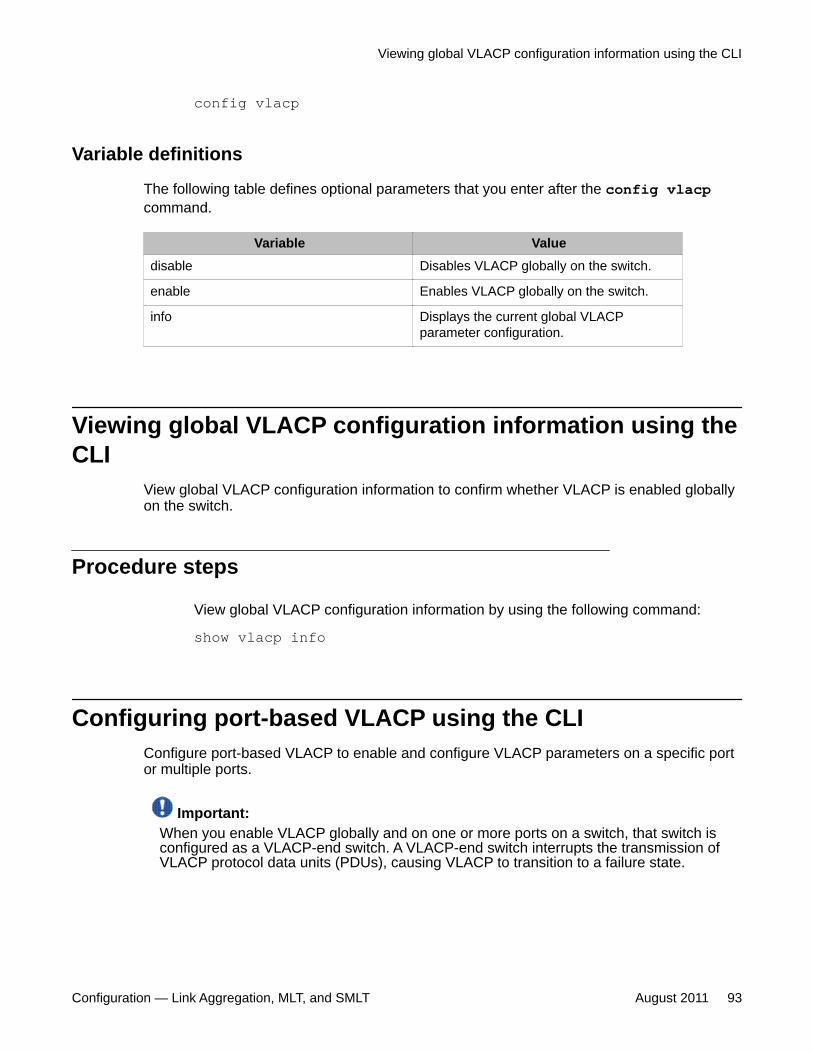
config vlacp
Variable definitions
The following table defines optional parameters that you enter after the config vlacpcommand.
Variable Valuedisable Disables VLACP globally on the switch.
enable Enables VLACP globally on the switch.
info Displays the current global VLACPparameter configuration.
Viewing global VLACP configuration information using theCLI
View global VLACP configuration information to confirm whether VLACP is enabled globallyon the switch.
Procedure steps
View global VLACP configuration information by using the following command:
show vlacp info
Configuring port-based VLACP using the CLIConfigure port-based VLACP to enable and configure VLACP parameters on a specific portor multiple ports.
Important:When you enable VLACP globally and on one or more ports on a switch, that switch isconfigured as a VLACP-end switch. A VLACP-end switch interrupts the transmission ofVLACP protocol data units (PDUs), causing VLACP to transition to a failure state.
Viewing global VLACP configuration information using the CLI
Configuration — Link Aggregation, MLT, and SMLT August 2011 93
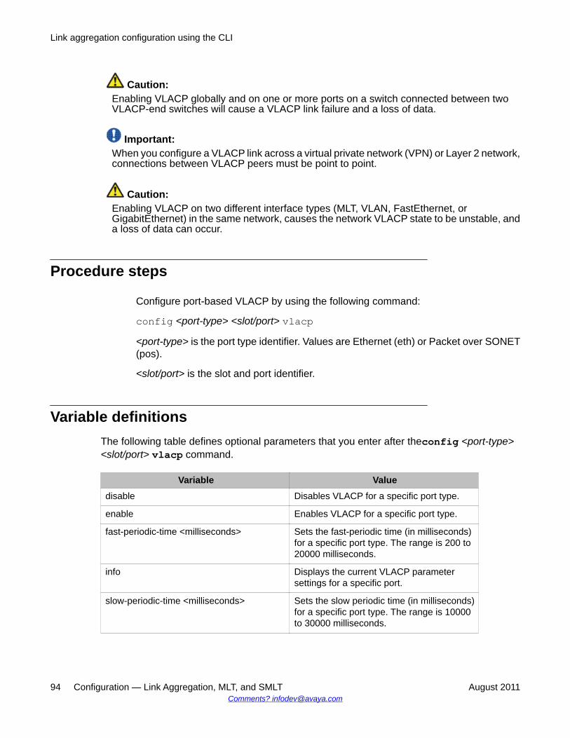
Caution:Enabling VLACP globally and on one or more ports on a switch connected between twoVLACP-end switches will cause a VLACP link failure and a loss of data.
Important:When you configure a VLACP link across a virtual private network (VPN) or Layer 2 network,connections between VLACP peers must be point to point.
Caution:Enabling VLACP on two different interface types (MLT, VLAN, FastEthernet, orGigabitEthernet) in the same network, causes the network VLACP state to be unstable, anda loss of data can occur.
Procedure steps
Configure port-based VLACP by using the following command:
config <port-type> <slot/port> vlacp<port-type> is the port type identifier. Values are Ethernet (eth) or Packet over SONET(pos).
<slot/port> is the slot and port identifier.
Variable definitionsThe following table defines optional parameters that you enter after theconfig <port-type><slot/port> vlacp command.
Variable Valuedisable Disables VLACP for a specific port type.
enable Enables VLACP for a specific port type.
fast-periodic-time <milliseconds> Sets the fast-periodic time (in milliseconds)for a specific port type. The range is 200 to20000 milliseconds.
info Displays the current VLACP parametersettings for a specific port.
slow-periodic-time <milliseconds> Sets the slow periodic time (in milliseconds)for a specific port type. The range is 10000to 30000 milliseconds.
Link aggregation configuration using the CLI
94 Configuration — Link Aggregation, MLT, and SMLT August 2011Comments? [email protected]
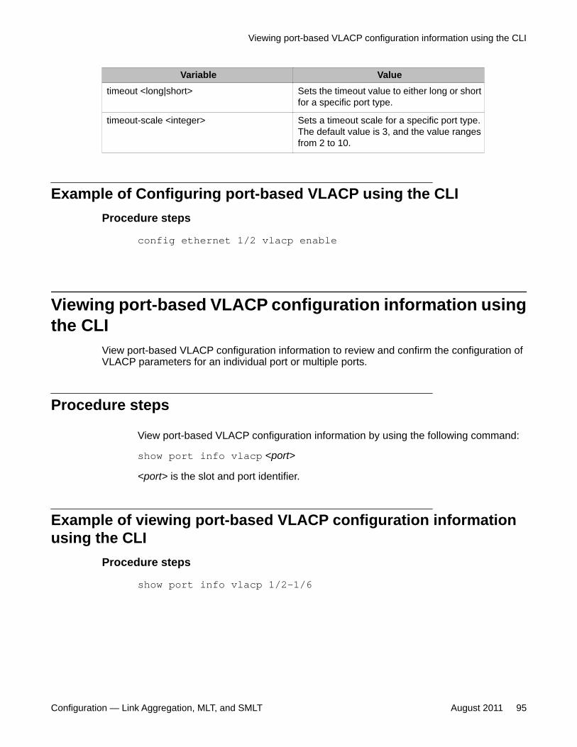
Variable Valuetimeout <long|short> Sets the timeout value to either long or short
for a specific port type.
timeout-scale <integer> Sets a timeout scale for a specific port type.The default value is 3, and the value rangesfrom 2 to 10.
Example of Configuring port-based VLACP using the CLIProcedure steps
config ethernet 1/2 vlacp enable
Viewing port-based VLACP configuration information usingthe CLI
View port-based VLACP configuration information to review and confirm the configuration ofVLACP parameters for an individual port or multiple ports.
Procedure steps
View port-based VLACP configuration information by using the following command:
show port info vlacp <port>
<port> is the slot and port identifier.
Example of viewing port-based VLACP configuration informationusing the CLI
Procedure steps
show port info vlacp 1/2-1/6
Viewing port-based VLACP configuration information using the CLI
Configuration — Link Aggregation, MLT, and SMLT August 2011 95

Link aggregation configuration using the CLI
96 Configuration — Link Aggregation, MLT, and SMLT August 2011Comments? [email protected]
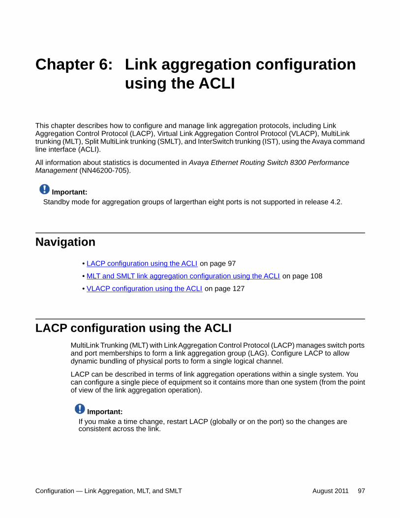
Chapter 6: Link aggregation configurationusing the ACLI
This chapter describes how to configure and manage link aggregation protocols, including LinkAggregation Control Protocol (LACP), Virtual Link Aggregation Control Protocol (VLACP), MultiLinktrunking (MLT), Split MultiLink trunking (SMLT), and InterSwitch trunking (IST), using the Avaya commandline interface (ACLI).
All information about statistics is documented in Avaya Ethernet Routing Switch 8300 PerformanceManagement (NN46200-705).
Important:Standby mode for aggregation groups of largerthan eight ports is not supported in release 4.2.
Navigation• LACP configuration using the ACLI on page 97
• MLT and SMLT link aggregation configuration using the ACLI on page 108
• VLACP configuration using the ACLI on page 127
LACP configuration using the ACLIMultiLink Trunking (MLT) with Link Aggregation Control Protocol (LACP) manages switch portsand port memberships to form a link aggregation group (LAG). Configure LACP to allowdynamic bundling of physical ports to form a single logical channel.
LACP can be described in terms of link aggregation operations within a single system. Youcan configure a single piece of equipment so it contains more than one system (from the pointof view of the link aggregation operation).
Important:If you make a time change, restart LACP (globally or on the port) so the changes areconsistent across the link.
Configuration — Link Aggregation, MLT, and SMLT August 2011 97
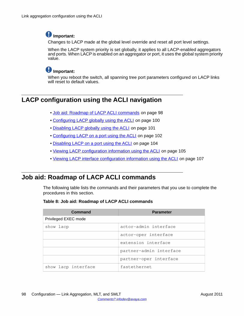
Important:Changes to LACP made at the global level override and reset all port level settings.
When the LACP system priority is set globally, it applies to all LACP-enabled aggregatorsand ports. When LACP is enabled on an aggregator or port, it uses the global system priorityvalue.
Important:When you reboot the switch, all spanning tree port parameters configured on LACP linkswill reset to default values.
LACP configuration using the ACLI navigation
• Job aid: Roadmap of LACP ACLI commands on page 98
• Configuring LACP globally using the ACLI on page 100
• Disabling LACP globally using the ACLI on page 101
• Configuring LACP on a port using the ACLI on page 102
• Disabling LACP on a port using the ACLI on page 104
• Viewing LACP configuration information using the ACLI on page 105
• Viewing LACP interface configuration information using the ACLI on page 107
Job aid: Roadmap of LACP ACLI commandsThe following table lists the commands and their parameters that you use to complete theprocedures in this section.
Table 8: Job aid: Roadmap of LACP ACLI commands
Command ParameterPrivileged EXEC mode
show lacp actor-admin interfaceactor-oper interfaceextension interfacepartner-admin interfacepartner-oper interface
show lacp interface fastethernet
Link aggregation configuration using the ACLI
98 Configuration — Link Aggregation, MLT, and SMLT August 2011Comments? [email protected]
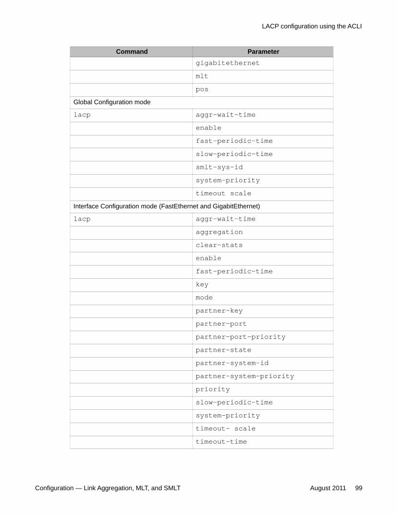
Command Parametergigabitethernetmltpos
Global Configuration mode
lacp aggr-wait-timeenablefast-periodic-timeslow-periodic-timesmlt-sys-idsystem-prioritytimeout scale
Interface Configuration mode (FastEthernet and GigabitEthernet)
lacp aggr-wait-timeaggregationclear-statsenablefast-periodic-timekeymodepartner-keypartner-portpartner-port-prioritypartner-statepartner-system-idpartner-system-prioritypriorityslow-periodic-timesystem-prioritytimeout- scaletimeout-time
LACP configuration using the ACLI
Configuration — Link Aggregation, MLT, and SMLT August 2011 99
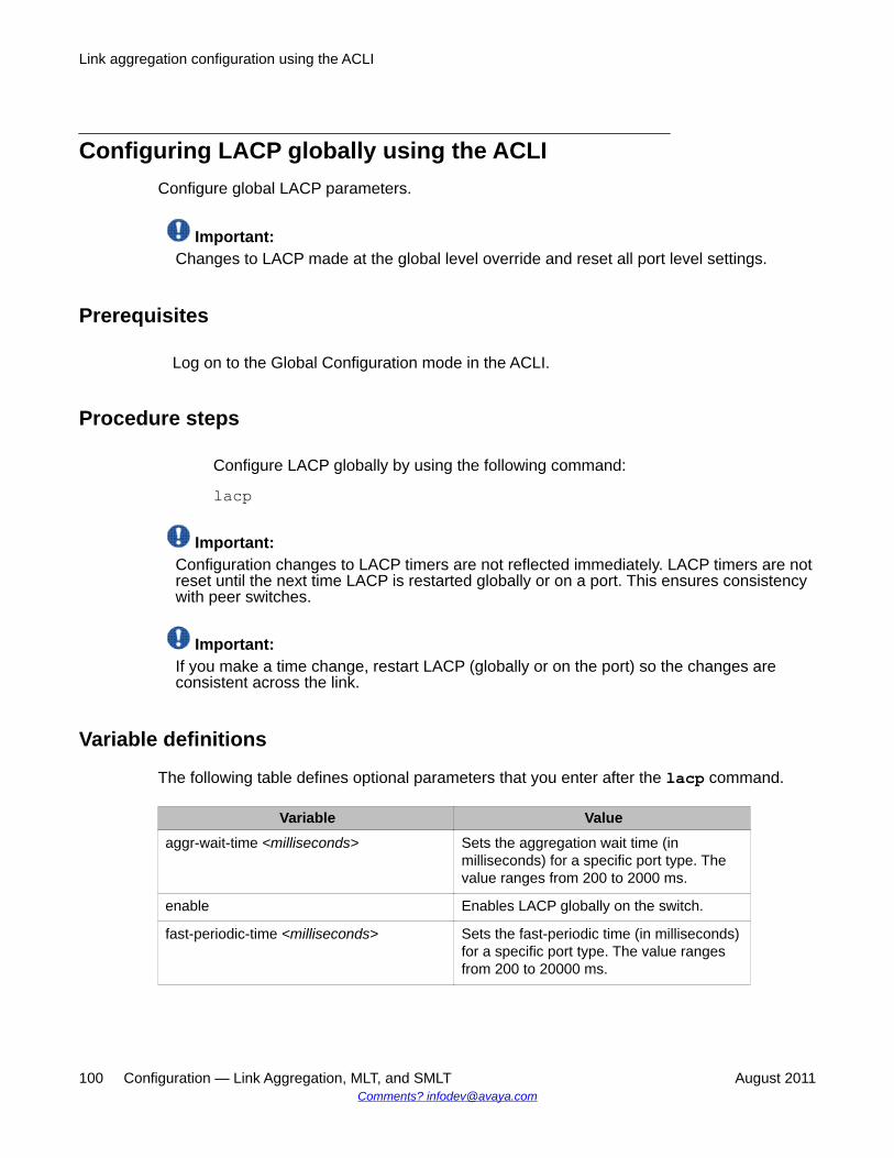
Configuring LACP globally using the ACLIConfigure global LACP parameters.
Important:Changes to LACP made at the global level override and reset all port level settings.
Prerequisites
Log on to the Global Configuration mode in the ACLI.
Procedure steps
Configure LACP globally by using the following command:
lacp
Important:Configuration changes to LACP timers are not reflected immediately. LACP timers are notreset until the next time LACP is restarted globally or on a port. This ensures consistencywith peer switches.
Important:If you make a time change, restart LACP (globally or on the port) so the changes areconsistent across the link.
Variable definitions
The following table defines optional parameters that you enter after the lacp command.
Variable Valueaggr-wait-time <milliseconds> Sets the aggregation wait time (in
milliseconds) for a specific port type. Thevalue ranges from 200 to 2000 ms.
enable Enables LACP globally on the switch.
fast-periodic-time <milliseconds> Sets the fast-periodic time (in milliseconds)for a specific port type. The value rangesfrom 200 to 20000 ms.
Link aggregation configuration using the ACLI
100 Configuration — Link Aggregation, MLT, and SMLT August 2011Comments? [email protected]

Variable Value
Important:If you make configuration changes to thefast periodic time value of an LAGmember, you must make the sameconfiguration changes to the fast periodictime value of all ports in the LAG andmember ports of the protocol partner.
slow-periodic-time <milliseconds> Sets the slow periodic time (in milliseconds)for a specific port type. The value rangesfrom 10 000 to 30 000 ms.
Important:If you make configuration changes to theslow periodic time value of an LAGmember, you must make the sameconfiguration changes to the slow periodictime value of all ports in the LAG andmember ports of the protocol partner.
smlt-sys-id Sets the LACP system ID globally.
system-priority Sets the LACP system priority globally. Thevalue ranges from 0 to 65 535. The defaultvalue is 32,768.
Important:Global LACP system-priority overwritesthe LACP system-priority of all LAGs andports. You must configure LACP system-priority for LAGs or ports on a switch to thesame value as the global LACP system-priority of that switch.
timeout-scale <integer> Sets a timeout scale for a specific port type.The value ranges from 2 to 10 and the defaultvalue is 3.
Disabling LACP globally using the ACLIDisable LACP globally on the switch.
LACP configuration using the ACLI
Configuration — Link Aggregation, MLT, and SMLT August 2011 101

Prerequisites
Log on to the Global Configuration mode in the ACLI.
Procedure steps
Disable LACP globally by using the following command:
no lacp
Configuring LACP on a port using the ACLIConfigure LACP parameters on specific ports.
Important:Changes made at the global level override and reset all port level settings.
Prerequisites
Log on to the FastEthernet or GigabitEthernet Interface Configuration mode in the ACLI forthe port you are configuring.
Procedure steps
Configure LACP on a port by using the following command:
lacp
Variable definitions
The following table defines optional parameters that you enter after the lacp command.
Variable Valueaggr-wait-time<milliseconds>
Sets the aggregation wait time (inmilliseconds) for a specific port type. Thevalue ranges from 200 to 2000 ms.
aggregation Enables lacp aggregation.
Link aggregation configuration using the ACLI
102 Configuration — Link Aggregation, MLT, and SMLT August 2011Comments? [email protected]
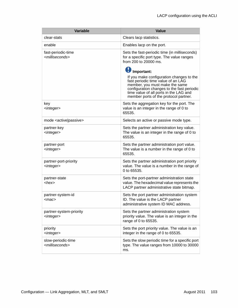
Variable Valueclear-stats Clears lacp statistics.
enable Enables lacp on the port.
fast-periodic-time<milliseconds>
Sets the fast-periodic time (in milliseconds)for a specific port type. The value rangesfrom 200 to 20000 ms.
Important:If you make configuration changes to thefast periodic time value of an LAGmember, you must make the sameconfiguration changes to the fast periodictime value of all ports in the LAG andmember ports of the protocol partner.
key<integer>
Sets the aggregation key for the port. Thevalue is an integer in the range of 0 to65535.
mode <active|passive> Selects an active or passive mode type.
partner-key<integer>
Sets the partner administration key value.The value is an integer in the range of 0 to65535.
partner-port<integer>
Sets the partner administration port value.The value is a number in the range of 0 to65535.
partner-port-priority<integer>
Sets the partner administration port priorityvalue. The value is a number in the range of0 to 65535.
partner-state<hex>
Sets the port-partner administration statevalue. The hexadecimal value represents theLACP partner administrative state bitmap.
partner-system-id<mac>
Sets the port partner administration systemID. The value is the LACP partneradministrative system ID MAC address.
partner-system-priority<integer>
Sets the partner administration systempriority value. The value is an integer in therange of 0 to 65535.
priority<integer>
Sets the port priority value. The value is aninteger in the range of 0 to 65535.
slow-periodic-time<milliseconds>
Sets the slow periodic time for a specific porttype. The value ranges from 10000 to 30000ms.
LACP configuration using the ACLI
Configuration — Link Aggregation, MLT, and SMLT August 2011 103
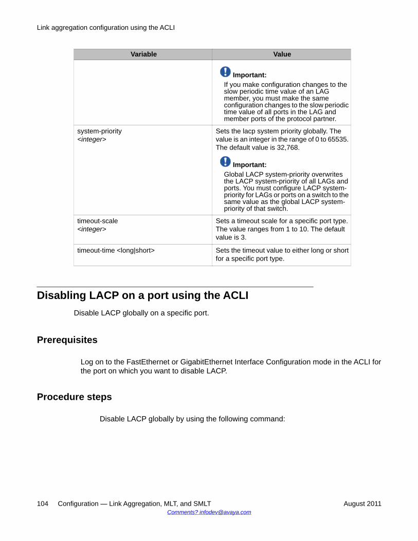
Variable Value
Important:If you make configuration changes to theslow periodic time value of an LAGmember, you must make the sameconfiguration changes to the slow periodictime value of all ports in the LAG andmember ports of the protocol partner.
system-priority<integer>
Sets the lacp system priority globally. Thevalue is an integer in the range of 0 to 65535.The default value is 32,768.
Important:Global LACP system-priority overwritesthe LACP system-priority of all LAGs andports. You must configure LACP system-priority for LAGs or ports on a switch to thesame value as the global LACP system-priority of that switch.
timeout-scale<integer>
Sets a timeout scale for a specific port type.The value ranges from 1 to 10. The defaultvalue is 3.
timeout-time <long|short> Sets the timeout value to either long or shortfor a specific port type.
Disabling LACP on a port using the ACLIDisable LACP globally on a specific port.
Prerequisites
Log on to the FastEthernet or GigabitEthernet Interface Configuration mode in the ACLI forthe port on which you want to disable LACP.
Procedure steps
Disable LACP globally by using the following command:
Link aggregation configuration using the ACLI
104 Configuration — Link Aggregation, MLT, and SMLT August 2011Comments? [email protected]
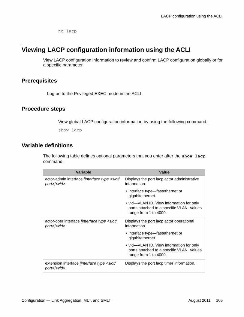
no lacp
Viewing LACP configuration information using the ACLIView LACP configuration information to review and confirm LACP configuration globally or fora specific parameter.
Prerequisites
Log on to the Privileged EXEC mode in the ACLI.
Procedure steps
View global LACP configuration information by using the following command:
show lacp
Variable definitions
The following table defines optional parameters that you enter after the show lacpcommand.
Variable Valueactor-admin interface [interface type <slot/port>]<vid>
Displays the port lacp actor administrativeinformation.
• interface type—fastethernet orgigabitethernet
• vid—VLAN ID. View information for onlyports attached to a specific VLAN. Valuesrange from 1 to 4000.
actor-oper interface [interface type <slot/port>]<vid>
Displays the port lacp actor operationalinformation.
• interface type—fastethernet orgigabitethernet
• vid—VLAN ID. View information for onlyports attached to a specific VLAN. Valuesrange from 1 to 4000.
extension interface [interface type <slot/port>]<vid>
Displays the port lacp timer information.
LACP configuration using the ACLI
Configuration — Link Aggregation, MLT, and SMLT August 2011 105

Variable Value
• interface type—fastethernet orgigabitethernet
• vid—VLAN ID. View information for onlyports attached to a specific VLAN. Valuesrange from 1 to 4000.
partner-admin interface [interface type <slot/port>]<vid>
Displays the port lacp partner administrativeinformation.
• interface type—fastethernet orgigabitethernet
• vid—VLAN ID. View information for onlyports attached to a specific VLAN. Valuesrange from 1 to 4000.
partner-oper interface [interface type <slot/port>]
Displays the port lacp partner operationalinformation. Interface type is fastethernet orgigabitethernet.
Job aid: show lacp output
The following table displays field descriptions for the show lacp command.
Table 9: Job aid: show lacp output
Field DescriptionSystemId: Displays the system ID.
SmltSystemId: Displays the global LACP system ID.
Lacp: Displays whether LACP is enabled or disabledglobally.
system-priority: Displays global LACP system priority information.
timeout-admin: Displays global administration timeout information.
fast-periodic-time-admin:
Displays the global administrative fast-periodic time inmilliseconds.
slow-periodic-time-admin:
Displays the global administrative slow-periodic timein milliseconds.
aggr-wait-time-admin: Displays the global administrative aggregation waittime in milliseconds.
timeout-oper Displays global operational timeout information.
Link aggregation configuration using the ACLI
106 Configuration — Link Aggregation, MLT, and SMLT August 2011Comments? [email protected]
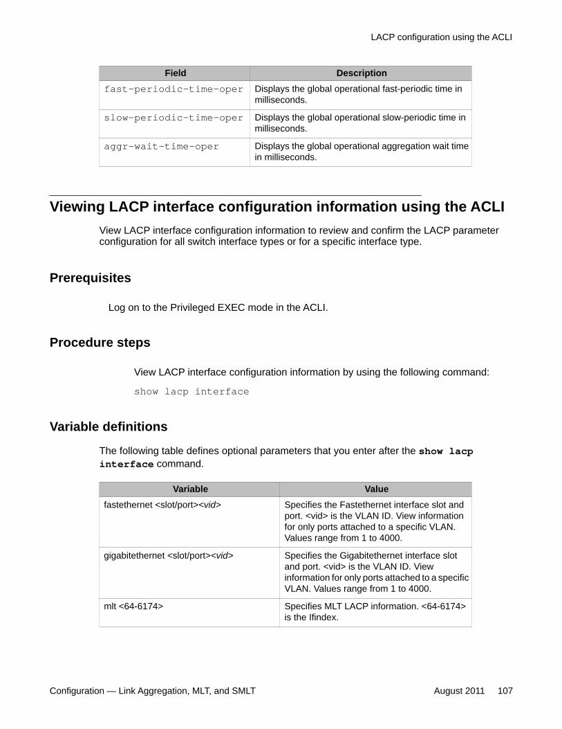
Field Descriptionfast-periodic-time-oper Displays the global operational fast-periodic time in
milliseconds.
slow-periodic-time-oper Displays the global operational slow-periodic time inmilliseconds.
aggr-wait-time-oper Displays the global operational aggregation wait timein milliseconds.
Viewing LACP interface configuration information using the ACLIView LACP interface configuration information to review and confirm the LACP parameterconfiguration for all switch interface types or for a specific interface type.
Prerequisites
Log on to the Privileged EXEC mode in the ACLI.
Procedure steps
View LACP interface configuration information by using the following command:
show lacp interface
Variable definitions
The following table defines optional parameters that you enter after the show lacpinterface command.
Variable Valuefastethernet <slot/port><vid> Specifies the Fastethernet interface slot and
port. <vid> is the VLAN ID. View informationfor only ports attached to a specific VLAN.Values range from 1 to 4000.
gigabitethernet <slot/port><vid> Specifies the Gigabitethernet interface slotand port. <vid> is the VLAN ID. Viewinformation for only ports attached to a specificVLAN. Values range from 1 to 4000.
mlt <64-6174> Specifies MLT LACP information. <64-6174>is the Ifindex.
LACP configuration using the ACLI
Configuration — Link Aggregation, MLT, and SMLT August 2011 107
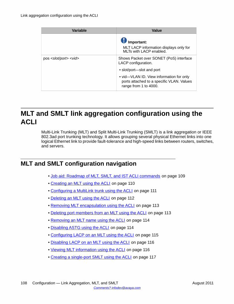
Variable Value
Important:MLT LACP information displays only forMLTs with LACP enabled.
pos <slot/port> <vid> Shows Packet over SONET (PoS) interfaceLACP configuration.
• slot/port—slot and port
• vid—VLAN ID. View information for onlyports attached to a specific VLAN. Valuesrange from 1 to 4000.
MLT and SMLT link aggregation configuration using theACLI
Multi-Link Trunking (MLT) and Split Multi-Link Trunking (SMLT) is a link aggregation or IEEE802.3ad port trunking technology. It allows grouping several physical Ethernet links into onelogical Ethernet link to provide fault-tolerance and high-speed links between routers, switches,and servers.
MLT and SMLT configuration navigation
• Job aid: Roadmap of MLT, SMLT, and IST ACLI commands on page 109
• Creating an MLT using the ACLI on page 110
• Configuring a MultiLink trunk using the ACLI on page 111
• Deleting an MLT using the ACLI on page 112
• Removing MLT encapsulation using the ACLI on page 113
• Deleting port members from an MLT using the ACLI on page 113
• Removing an MLT name using the ACLI on page 114
• Disabling ASTG using the ACLI on page 114
• Configuring LACP on an MLT using the ACLI on page 115
• Disabling LACP on an MLT using the ACLI on page 116
• Viewing MLT information using the ACLI on page 116
• Creating a single-port SMLT using the ACLI on page 117
Link aggregation configuration using the ACLI
108 Configuration — Link Aggregation, MLT, and SMLT August 2011Comments? [email protected]
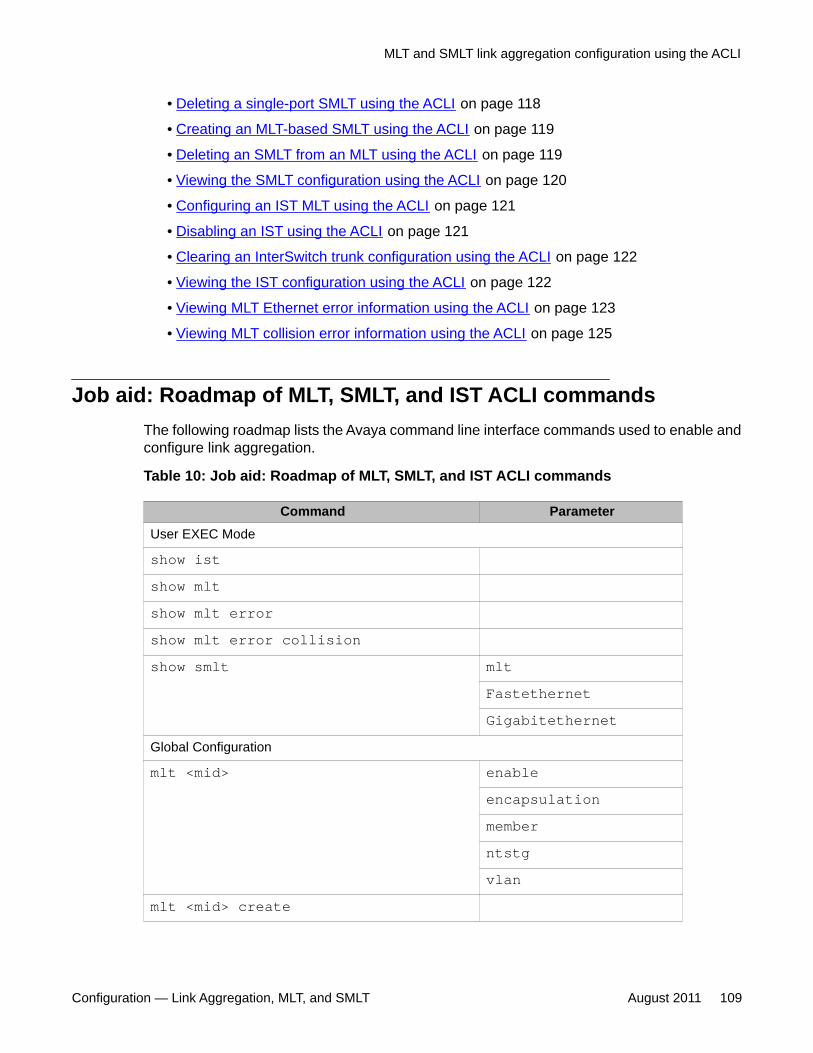
• Deleting a single-port SMLT using the ACLI on page 118
• Creating an MLT-based SMLT using the ACLI on page 119
• Deleting an SMLT from an MLT using the ACLI on page 119
• Viewing the SMLT configuration using the ACLI on page 120
• Configuring an IST MLT using the ACLI on page 121
• Disabling an IST using the ACLI on page 121
• Clearing an InterSwitch trunk configuration using the ACLI on page 122
• Viewing the IST configuration using the ACLI on page 122
• Viewing MLT Ethernet error information using the ACLI on page 123
• Viewing MLT collision error information using the ACLI on page 125
Job aid: Roadmap of MLT, SMLT, and IST ACLI commandsThe following roadmap lists the Avaya command line interface commands used to enable andconfigure link aggregation.
Table 10: Job aid: Roadmap of MLT, SMLT, and IST ACLI commands
Command ParameterUser EXEC Mode
show istshow mltshow mlt errorshow mlt error collisionshow smlt mlt
FastethernetGigabitethernet
Global Configuration
mlt <mid> enableencapsulationmemberntstgvlan
mlt <mid> create
MLT and SMLT link aggregation configuration using the ACLI
Configuration — Link Aggregation, MLT, and SMLT August 2011 109
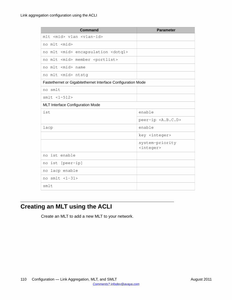
Command Parametermlt <mid> vlan <vlan-id>no mlt <mid>no mlt <mid> encapsulation <dotq1>no mlt <mid> member <portlist>no mlt <mid> nameno mlt <mid> ntstgFastethernet or Gigabitethernet Interface Configuration Mode
no smltsmlt <1-512>MLT Interface Configuration Mode
ist enablepeer-ip <A.B.C.D>
lacp enablekey <integer>system-priority<integer>
no ist enableno ist [peer-ip]no lacp enableno smlt <1-31>smlt
Creating an MLT using the ACLICreate an MLT to add a new MLT to your network.
Link aggregation configuration using the ACLI
110 Configuration — Link Aggregation, MLT, and SMLT August 2011Comments? [email protected]
Prerequisites
Log on to the Global Configuration mode in the ACLI.
Procedure steps
Create an MLT by using the following command:
mlt <mid> create<mid> is the MLT identifier. Values range from 1 to 7 for FastEthernet ports, up to 7MLTs (IDs 1—7) are supported. Values range from 1 to 31 for Gigabit Ethernet and 10Gigabit Ethernet ports, up to 31 MLTs (IDs 1—31) are supported.
Configuring a MultiLink trunk using the ACLIConfigure a MultiLink trunk to create and manage a new MLT or manage an existing MLT inyour network.
Prerequisites
Log on to the Global Configuration mode in the ACLI.
Procedure steps
Configure an MLT by using the following command:
mlt <mid><mid> is the MLT identifier. Values range from 1 to 7 for FastEthernet ports, up to 7MLTs (IDs 1—7) are supported. Values range from 1 to 31 for Gigabit Ethernet and 10Gigabit Ethernet ports, up to 31 MLTs (IDs 1—31) are supported.
Variable definitions
The following table defines optional parameters that you enter after the mlt <mid>command.
MLT and SMLT link aggregation configuration using the ACLI
Configuration — Link Aggregation, MLT, and SMLT August 2011 111
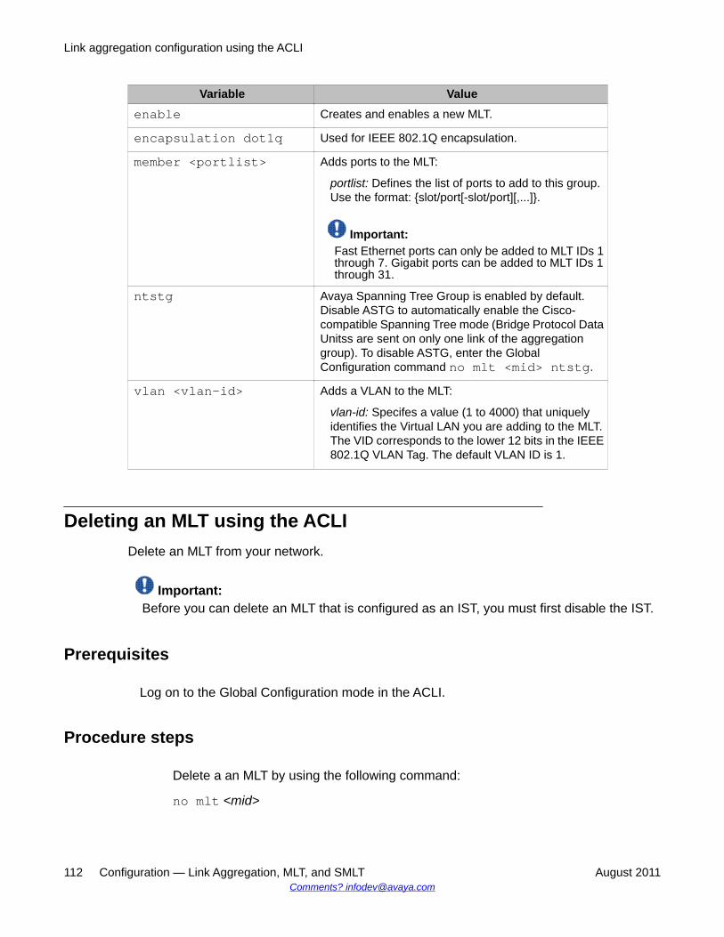
Variable Valueenable Creates and enables a new MLT.
encapsulation dot1q Used for IEEE 802.1Q encapsulation.
member <portlist> Adds ports to the MLT:
portlist: Defines the list of ports to add to this group.Use the format: {slot/port[-slot/port][,...]}.
Important:Fast Ethernet ports can only be added to MLT IDs 1through 7. Gigabit ports can be added to MLT IDs 1through 31.
ntstg Avaya Spanning Tree Group is enabled by default.Disable ASTG to automatically enable the Cisco-compatible Spanning Tree mode (Bridge Protocol DataUnitss are sent on only one link of the aggregationgroup). To disable ASTG, enter the GlobalConfiguration command no mlt <mid> ntstg.
vlan <vlan-id> Adds a VLAN to the MLT:
vlan-id: Specifes a value (1 to 4000) that uniquelyidentifies the Virtual LAN you are adding to the MLT.The VID corresponds to the lower 12 bits in the IEEE802.1Q VLAN Tag. The default VLAN ID is 1.
Deleting an MLT using the ACLIDelete an MLT from your network.
Important:Before you can delete an MLT that is configured as an IST, you must first disable the IST.
Prerequisites
Log on to the Global Configuration mode in the ACLI.
Procedure steps
Delete a an MLT by using the following command:
no mlt <mid>
Link aggregation configuration using the ACLI
112 Configuration — Link Aggregation, MLT, and SMLT August 2011Comments? [email protected]
<mid> is the MLT identifier. Values range from 1 to 7 for FastEthernet ports, up to 7MLTs (IDs 1—7) are supported. Values range from 1 to 31 for Gigabit Ethernet and 10Gigabit Ethernet ports, up to 31 MLTs (IDs 1—31) are supported.
Removing MLT encapsulation using the ACLIRemove encapsulation from an MLT to disable trunking on the MLT.
Prerequisites
Log on to the Global Configuration mode in the ACLI.
Procedure steps
Remove encapsulation from an MLT by using the following command:
no mlt <mid> encapsulation dot1q
Deleting port members from an MLT using the ACLIDelete port members from an MLT to reduce the number of ports assembled in the logicallink.
Prerequisites
Log on to the Global Configuration mode in the ACLI.
Procedure steps
Remove port members from an MLT by using the following command:
no mlt <mid> member <portlist>
<mid> is the MLT identifier. Values range from 1 to 7 for FastEthernet ports, up to 7MLTs (IDs 1—7) are supported. Values range from 1 to 31 for Gigabit Ethernet and 10Gigabit Ethernet ports, up to 31 MLTs (IDs 1—31) are supported.
MLT and SMLT link aggregation configuration using the ACLI
Configuration — Link Aggregation, MLT, and SMLT August 2011 113
<portlist> identifies a port of list of ports, in the format: {slot/port[-slot/port][,...]}
Removing an MLT name using the ACLIRemove an MLT name.
Prerequisites
Log on to the Global Configuration mode in the ACLI.
Procedure steps
Remove an MLT name by using the following command:
no mlt <mid> name<mid> is the MLT identifier. Values range from 1 to 7 for FastEthernet ports, up to 7MLTs (IDs 1—7) are supported. Values range from 1 to 31 for Gigabit Ethernet and 10Gigabit Ethernet ports, up to 31 MLTs (IDs 1—31) are supported.
Disabling ASTG using the ACLIDisable Avaya Spanning Tree Group (ASTG) to automatically enable the Cisco compatibleSpanning Tree mode. The ASTG is enabled by default.
Prerequisites
Log on to the Global Configuration mode in the ACLI.
Procedure steps
Disable NTSTG by using the following command:
no mlt <mid> ntstg
Link aggregation configuration using the ACLI
114 Configuration — Link Aggregation, MLT, and SMLT August 2011Comments? [email protected]
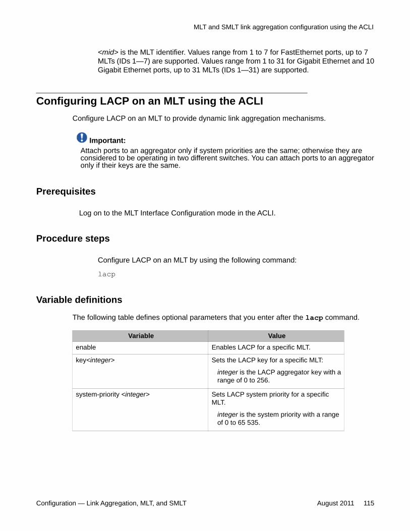
<mid> is the MLT identifier. Values range from 1 to 7 for FastEthernet ports, up to 7MLTs (IDs 1—7) are supported. Values range from 1 to 31 for Gigabit Ethernet and 10Gigabit Ethernet ports, up to 31 MLTs (IDs 1—31) are supported.
Configuring LACP on an MLT using the ACLIConfigure LACP on an MLT to provide dynamic link aggregation mechanisms.
Important:Attach ports to an aggregator only if system priorities are the same; otherwise they areconsidered to be operating in two different switches. You can attach ports to an aggregatoronly if their keys are the same.
Prerequisites
Log on to the MLT Interface Configuration mode in the ACLI.
Procedure steps
Configure LACP on an MLT by using the following command:
lacp
Variable definitions
The following table defines optional parameters that you enter after the lacp command.
Variable Valueenable Enables LACP for a specific MLT.
key<integer> Sets the LACP key for a specific MLT:
integer is the LACP aggregator key with arange of 0 to 256.
system-priority <integer> Sets LACP system priority for a specificMLT.
integer is the system priority with a rangeof 0 to 65 535.
MLT and SMLT link aggregation configuration using the ACLI
Configuration — Link Aggregation, MLT, and SMLT August 2011 115
Disabling LACP on an MLT using the ACLIDisable the LACP on an MLT to discontinue providing dynamic link aggregationmechanisms.
Prerequisites
Log on to the MLT Interface Configuration mode in the ACLI.
Procedure steps
Disable the LACP on an MLT by using the following command:
no lacp enable
Viewing MLT information using the ACLIYou can view configuration information about all MLTs or a specific MLT configured on aswitch.
Prerequisites
Log on to the Privileged EXEC mode in the ACLI.
Procedure steps
View MLT configuration information by using the following command:
show mlt
Variable definitions
The following table defines optional parameters that you enter after the show mltcommand.
Link aggregation configuration using the ACLI
116 Configuration — Link Aggregation, MLT, and SMLT August 2011Comments? [email protected]
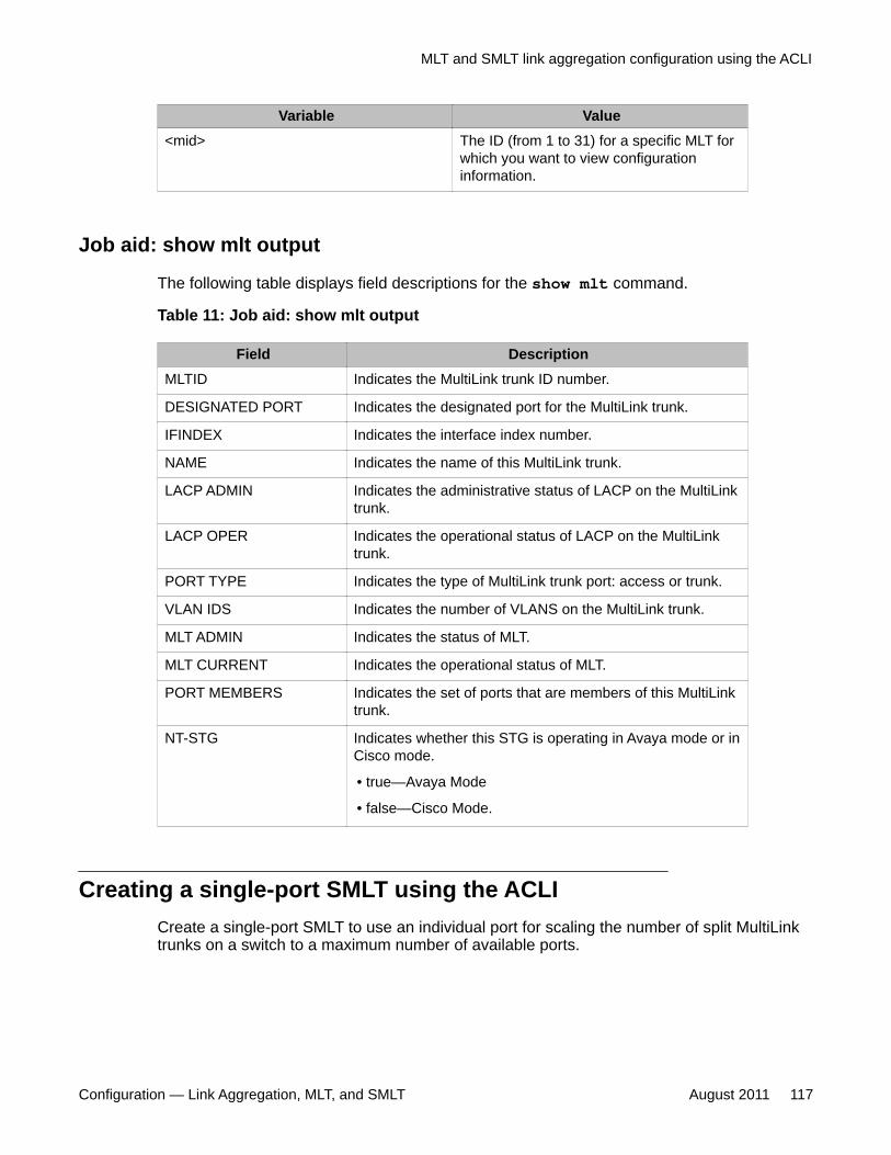
Variable Value<mid> The ID (from 1 to 31) for a specific MLT for
which you want to view configurationinformation.
Job aid: show mlt output
The following table displays field descriptions for the show mlt command.
Table 11: Job aid: show mlt output
Field DescriptionMLTID Indicates the MultiLink trunk ID number.
DESIGNATED PORT Indicates the designated port for the MultiLink trunk.
IFINDEX Indicates the interface index number.
NAME Indicates the name of this MultiLink trunk.
LACP ADMIN Indicates the administrative status of LACP on the MultiLinktrunk.
LACP OPER Indicates the operational status of LACP on the MultiLinktrunk.
PORT TYPE Indicates the type of MultiLink trunk port: access or trunk.
VLAN IDS Indicates the number of VLANS on the MultiLink trunk.
MLT ADMIN Indicates the status of MLT.
MLT CURRENT Indicates the operational status of MLT.
PORT MEMBERS Indicates the set of ports that are members of this MultiLinktrunk.
NT-STG Indicates whether this STG is operating in Avaya mode or inCisco mode.
• true—Avaya Mode
• false—Cisco Mode.
Creating a single-port SMLT using the ACLICreate a single-port SMLT to use an individual port for scaling the number of split MultiLinktrunks on a switch to a maximum number of available ports.
MLT and SMLT link aggregation configuration using the ACLI
Configuration — Link Aggregation, MLT, and SMLT August 2011 117
Prerequisites
Log on to the Fastethernet or Gigabitethernet Interface Configuration mode in the ACLI, forthe port, on which you want to create an SMLT.
Procedure steps
Create a single-port SMLT by using the following command:
smlt <1-512><1-512> identifies the SMLT ID. Values range from 1 to 512.
Deleting a single-port SMLT using the ACLIDelete an SMLT from and individual port.
Prerequisites
Log on to the Fastethernet or Gigabitethernet Interface Configuration mode in the ACLI, forthe port, from which you want to delete an SMLT.
Procedure steps
Delete a single-port SMLT by using the following command:
no smlt
Configuring rate limiting using the ACLIConfigure rate limiting to limit all packets with broadcast and multicast addresses to control theamount of user traffic.
Link aggregation configuration using the ACLI
118 Configuration — Link Aggregation, MLT, and SMLT August 2011Comments? [email protected]
Prerequisites
Log on to the Interface Configuration mode in the ACLI.
Procedure steps
Configure by using the following command:
bcast-mcast-rate-limit <percent value> enable<percent value> identifies the rate limit expressed as a percentage. Values range from1 to 100.
Creating an MLT-based SMLT using the ACLICreate an MLT-based SMLT to improve the level of Layer 2/Layer 3 resiliency by providingnodal protection in addition to link failure protection and flexible bandwidth scaling.
Prerequisites
• You must create an MLT before you can create an SMLT.
• Log on to the MLT Interface Configuration mode in the ACLI, for the MLT, on which youwant to create an SMLT.
Procedure steps
Create an SMLT by using the following command:
smlt <1-31><1-31> identifies the SMLT ID. Values range from 1 to 31.
Deleting an SMLT from an MLT using the ACLIDelete an SMLT from an MLT.
MLT and SMLT link aggregation configuration using the ACLI
Configuration — Link Aggregation, MLT, and SMLT August 2011 119

Prerequisites
Log on to the MLT Interface Configuration mode in the ACLI, for the MLT, from which youwant to delete an SMLT.
Procedure steps
Delete an SMLT by using the following command:
no smlt
Viewing the SMLT configuration using the ACLIYou can view SMLT information for an MLT, a Fastethernet port, or a Gigabitethernet port.
Prerequisites
Log on to the User EXEC mode in the ACLI.
Procedure steps
View the SMLT and single-port SMLT configurations by using the following command:
show smlt
Variable definitions
The following table defines optional parameters that you enter after the show smltcommand.
Parameter Descriptionmlt <mid> Displays MLT-based SMLT information. The ID (from 1 to 31)
for a specific MLT for which you want to view SMLTinformation.
Fastethernet <ports> Displays the Fastethernet port-based SMLTs.List one or more ports by using the format {slot/port[-slot/port][,...]}.
Gigabitethernet <ports> Displays the Gigabitethernet port-based SMLTs.
Link aggregation configuration using the ACLI
120 Configuration — Link Aggregation, MLT, and SMLT August 2011Comments? [email protected]
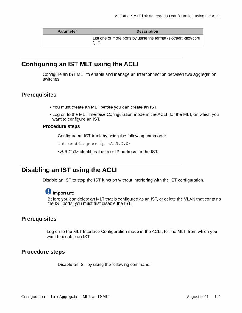
Parameter DescriptionList one or more ports by using the format {slot/port[-slot/port][,...]}.
Configuring an IST MLT using the ACLIConfigure an IST MLT to enable and manage an interconnection between two aggregationswitches.
Prerequisites
• You must create an MLT before you can create an IST.• Log on to the MLT Interface Configuration mode in the ACLI, for the MLT, on which you
want to configure an IST.
Procedure steps
Configure an IST trunk by using the following command:
ist enable peer-ip <A.B.C.D>
<A.B.C.D> identifies the peer IP address for the IST.
Disabling an IST using the ACLIDisable an IST to stop the IST function without interfering with the IST configuration.
Important:Before you can delete an MLT that is configured as an IST, or delete the VLAN that containsthe IST ports, you must first disable the IST.
Prerequisites
Log on to the MLT Interface Configuration mode in the ACLI, for the MLT, from which youwant to disable an IST.
Procedure steps
Disable an IST by using the following command:
MLT and SMLT link aggregation configuration using the ACLI
Configuration — Link Aggregation, MLT, and SMLT August 2011 121
no ist enable
Clearing an InterSwitch trunk configuration using the ACLIClear an IST configuration to remove the IST from your network.
Important:Before you can delete an MLT that is configured as an IST, or delete the VLAN that containsthe IST ports, you must first disable the IST.
Prerequisites
Log on to the MLT Interface Configuration mode in the ACLI, for the MLT, from which youwant to clear an IST.
Procedure steps
Clear an IST configuration by using the following command:
no ist peer-ip
Viewing the IST configuration using the ACLIYou can view the IST configuration on the switch.
Prerequisites
Log on to the User EXEC mode in the ACLI.
Procedure steps
View the IST configuration on the switch by using the following command:
Link aggregation configuration using the ACLI
122 Configuration — Link Aggregation, MLT, and SMLT August 2011Comments? [email protected]
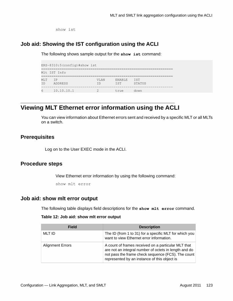
show ist
Job aid: Showing the IST configuration using the ACLI
The following shows sample output for the show ist command:
ERS-8310:5(config)#show ist================================================================Mlt IST Info================================================================MLT IP VLAN ENABLE ISTID ADDRESS ID IST STATUS ----------------------------------------------------------------6 10.10.10.1 2 true down
Viewing MLT Ethernet error information using the ACLIYou can view information about Ethernet errors sent and received by a specific MLT or all MLTson a switch.
Prerequisites
Log on to the User EXEC mode in the ACLI.
Procedure steps
View Ethernet error information by using the following command:
show mlt error
Job aid: show mlt error output
The following table displays field descriptions for the show mlt error command.
Table 12: Job aid: show mlt error output
Field DescriptionMLT ID The ID (from 1 to 31) for a specific MLT for which you
want to view Ethernet error information.
Alignment Errors A count of frames received on a particular MLT thatare not an integral number of octets in length and donot pass the frame check sequence (FCS). The countrepresented by an instance of this object is
MLT and SMLT link aggregation configuration using the ACLI
Configuration — Link Aggregation, MLT, and SMLT August 2011 123
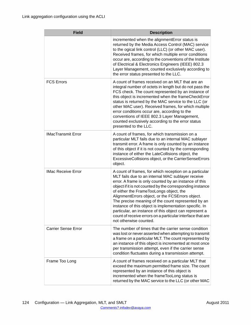
Field Descriptionincremented when the alignmentError status isreturned by the Media Access Control (MAC) serviceto the ogical link control (LLC) (or other MAC user).Received frames, for which multiple error conditionsoccur are, according to the conventions of the Instituteof Electrical & Electronics Engineers (IEEE) 802.3Layer Management, counted exclusively according tothe error status presented to the LLC.
FCS Errors A count of frames received on an MLT that are anintegral number of octets in length but do not pass theFCS check. The count represented by an instance ofthis object is incremented when the frameCheckErrorstatus is returned by the MAC service to the LLC (orother MAC user). Received frames, for which multipleerror conditions occur are, according to theconventions of IEEE 802.3 Layer Management,counted exclusively according to the error statuspresented to the LLC.
IMacTransmit Error A count of frames, for which transmission on aparticular MLT fails due to an internal MAC sublayertransmit error. A frame is only counted by an instanceof this object if it is not counted by the correspondinginstance of either the LateCollisions object, theExcessiveCollisions object, or the CarrierSenseErrorsobject.
IMac Receive Error A count of frames, for which reception on a particularMLT fails due to an internal MAC sublayer receiveerror. A frame is only counted by an instance of thisobject if it is not counted by the corresponding instanceof either the FrameTooLongs object, theAlignmentErrors object, or the FCSErrors object.The precise meaning of the count represented by aninstance of this object is implementation specific. Inparticular, an instance of this object can represent acount of receive errors on a particular interface that arenot otherwise counted.
Carrier Sense Error The number of times that the carrier sense conditionwas lost or never asserted when attempting to transmita frame on a particular MLT. The count represented byan instance of this object is incremented at most onceper transmission attempt, even if the carrier sensecondition fluctuates during a transmission attempt.
Frame Too Long A count of frames received on a particular MLT thatexceed the maximum permitted frame size. The countrepresented by an instance of this object isincremented when the frameTooLong status isreturned by the MAC service to the LLC (or other MAC
Link aggregation configuration using the ACLI
124 Configuration — Link Aggregation, MLT, and SMLT August 2011Comments? [email protected]
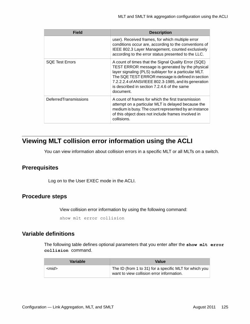
Field Descriptionuser). Received frames, for which multiple errorconditions occur are, according to the conventions ofIEEE 802.3 Layer Management, counted exclusivelyaccording to the error status presented to the LLC.
SQE Test Errors A count of times that the Signal Quality Error (SQE)TEST ERROR message is generated by the physicallayer signaling (PLS) sublayer for a particular MLT.The SQE TEST ERROR message is defined in section7.2.2.2.4 of ANSI/IEEE 802.3-1985, and its generationis described in section 7.2.4.6 of the samedocument.
DeferredTransmissions A count of frames for which the first transmissionattempt on a particular MLT is delayed because themedium is busy. The count represented by an instanceof this object does not include frames involved incollisions.
Viewing MLT collision error information using the ACLIYou can view information about collision errors in a specific MLT or all MLTs on a switch.
Prerequisites
Log on to the User EXEC mode in the ACLI.
Procedure steps
View collision error information by using the following command:
show mlt error collision
Variable definitions
The following table defines optional parameters that you enter after the show mlt errorcollision command.
Variable Value<mid> The ID (from 1 to 31) for a specific MLT for which you
want to view collision error information.
MLT and SMLT link aggregation configuration using the ACLI
Configuration — Link Aggregation, MLT, and SMLT August 2011 125
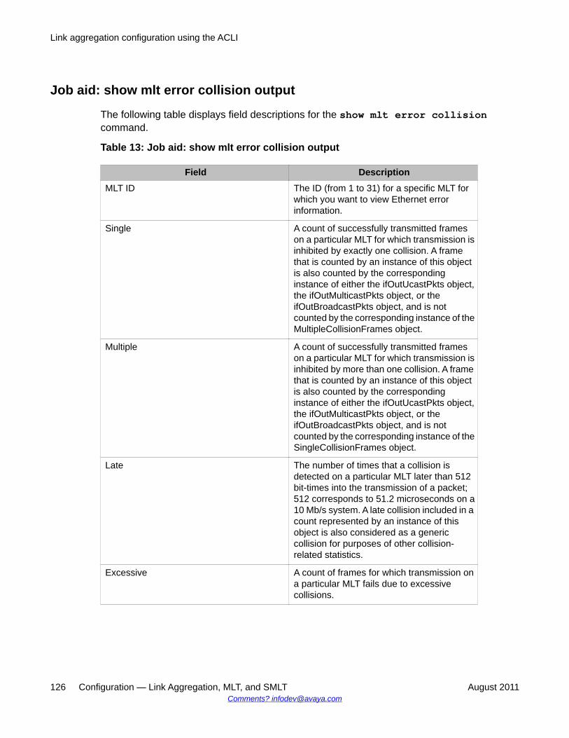
Job aid: show mlt error collision output
The following table displays field descriptions for the show mlt error collisioncommand.
Table 13: Job aid: show mlt error collision output
Field DescriptionMLT ID The ID (from 1 to 31) for a specific MLT for
which you want to view Ethernet errorinformation.
Single A count of successfully transmitted frameson a particular MLT for which transmission isinhibited by exactly one collision. A framethat is counted by an instance of this objectis also counted by the correspondinginstance of either the ifOutUcastPkts object,the ifOutMulticastPkts object, or theifOutBroadcastPkts object, and is notcounted by the corresponding instance of theMultipleCollisionFrames object.
Multiple A count of successfully transmitted frameson a particular MLT for which transmission isinhibited by more than one collision. A framethat is counted by an instance of this objectis also counted by the correspondinginstance of either the ifOutUcastPkts object,the ifOutMulticastPkts object, or theifOutBroadcastPkts object, and is notcounted by the corresponding instance of theSingleCollisionFrames object.
Late The number of times that a collision isdetected on a particular MLT later than 512bit-times into the transmission of a packet;512 corresponds to 51.2 microseconds on a10 Mb/s system. A late collision included in acount represented by an instance of thisobject is also considered as a genericcollision for purposes of other collision-related statistics.
Excessive A count of frames for which transmission ona particular MLT fails due to excessivecollisions.
Link aggregation configuration using the ACLI
126 Configuration — Link Aggregation, MLT, and SMLT August 2011Comments? [email protected]
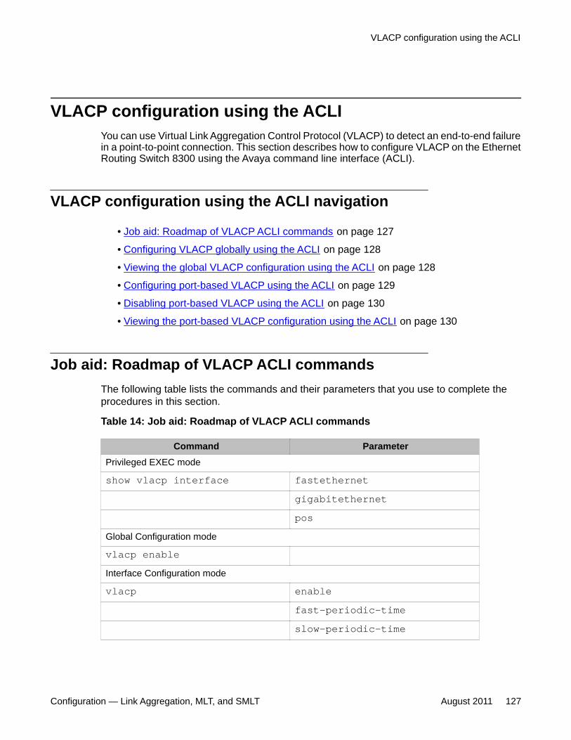
VLACP configuration using the ACLIYou can use Virtual Link Aggregation Control Protocol (VLACP) to detect an end-to-end failurein a point-to-point connection. This section describes how to configure VLACP on the EthernetRouting Switch 8300 using the Avaya command line interface (ACLI).
VLACP configuration using the ACLI navigation
• Job aid: Roadmap of VLACP ACLI commands on page 127
• Configuring VLACP globally using the ACLI on page 128
• Viewing the global VLACP configuration using the ACLI on page 128
• Configuring port-based VLACP using the ACLI on page 129
• Disabling port-based VLACP using the ACLI on page 130
• Viewing the port-based VLACP configuration using the ACLI on page 130
Job aid: Roadmap of VLACP ACLI commandsThe following table lists the commands and their parameters that you use to complete theprocedures in this section.
Table 14: Job aid: Roadmap of VLACP ACLI commands
Command ParameterPrivileged EXEC mode
show vlacp interface fastethernetgigabitethernetpos
Global Configuration mode
vlacp enableInterface Configuration mode
vlacp enablefast-periodic-timeslow-periodic-time
VLACP configuration using the ACLI
Configuration — Link Aggregation, MLT, and SMLT August 2011 127
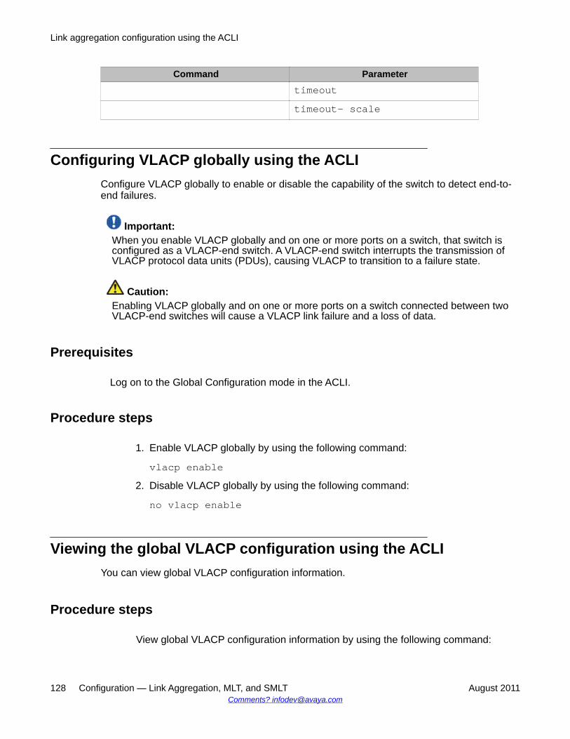
Command Parametertimeouttimeout- scale
Configuring VLACP globally using the ACLIConfigure VLACP globally to enable or disable the capability of the switch to detect end-to-end failures.
Important:When you enable VLACP globally and on one or more ports on a switch, that switch isconfigured as a VLACP-end switch. A VLACP-end switch interrupts the transmission ofVLACP protocol data units (PDUs), causing VLACP to transition to a failure state.
Caution:Enabling VLACP globally and on one or more ports on a switch connected between twoVLACP-end switches will cause a VLACP link failure and a loss of data.
Prerequisites
Log on to the Global Configuration mode in the ACLI.
Procedure steps
1. Enable VLACP globally by using the following command:
vlacp enable2. Disable VLACP globally by using the following command:
no vlacp enable
Viewing the global VLACP configuration using the ACLIYou can view global VLACP configuration information.
Procedure steps
View global VLACP configuration information by using the following command:
Link aggregation configuration using the ACLI
128 Configuration — Link Aggregation, MLT, and SMLT August 2011Comments? [email protected]
show vlacp
Configuring port-based VLACP using the ACLIConfigure port-based VLACP to enable and manage the capability of an interface to detectend-to-end failures.
Important:When you enable VLACP globally and on one or more ports on a switch, that switch isconfigured as a VLACP-end switch. A VLACP-end switch interrupts the transmission ofVLACP protocol data units (PDUs), causing VLACP to transition to a failure state.
Caution:Enabling VLACP globally and on one or more ports on a switch connected between twoVLACP-end switches will cause a VLACP link failure and a loss of data.
Important:When you configure a VLACP link across a virtual private network (VPN) or Layer 2 network,connections between VLACP peers must be point to point.
Caution:Enabling VLACP on two different interface types (MLT, VLAN, FastEthernet, orGigabitEthernet) in the same network, causes the network VLACP state to be unstable, anda loss of data can occur.
Prerequisites
Log on to the Interface Configuration mode in the ACLI.
Procedure steps
Configure port-based VLACP by using the following command:
vlacp
Variable definitions
The following table defines optional parameters that you enter after the vlacp command.
VLACP configuration using the ACLI
Configuration — Link Aggregation, MLT, and SMLT August 2011 129
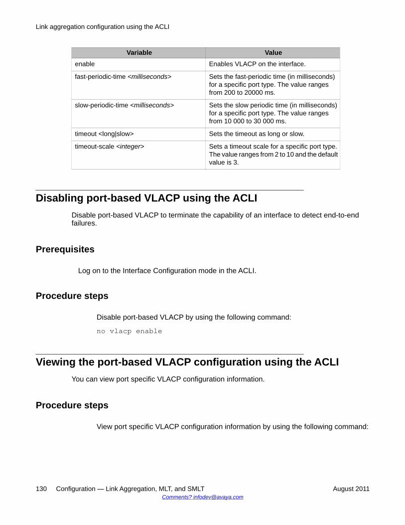
Variable Valueenable Enables VLACP on the interface.
fast-periodic-time <milliseconds> Sets the fast-periodic time (in milliseconds)for a specific port type. The value rangesfrom 200 to 20000 ms.
slow-periodic-time <milliseconds> Sets the slow periodic time (in milliseconds)for a specific port type. The value rangesfrom 10 000 to 30 000 ms.
timeout <long|slow> Sets the timeout as long or slow.
timeout-scale <integer> Sets a timeout scale for a specific port type.The value ranges from 2 to 10 and the defaultvalue is 3.
Disabling port-based VLACP using the ACLIDisable port-based VLACP to terminate the capability of an interface to detect end-to-endfailures.
Prerequisites
Log on to the Interface Configuration mode in the ACLI.
Procedure steps
Disable port-based VLACP by using the following command:
no vlacp enable
Viewing the port-based VLACP configuration using the ACLIYou can view port specific VLACP configuration information.
Procedure steps
View port specific VLACP configuration information by using the following command:
Link aggregation configuration using the ACLI
130 Configuration — Link Aggregation, MLT, and SMLT August 2011Comments? [email protected]
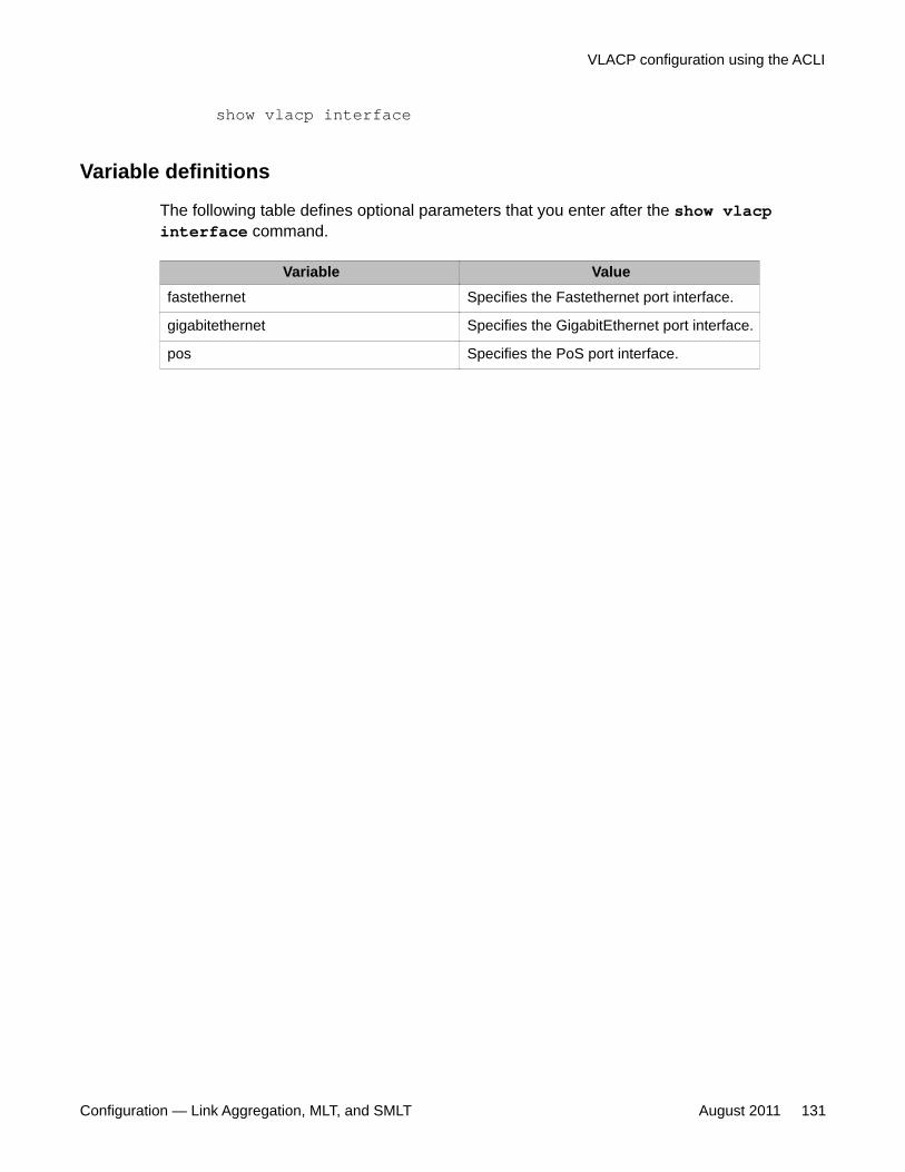
show vlacp interface
Variable definitions
The following table defines optional parameters that you enter after the show vlacpinterface command.
Variable Valuefastethernet Specifies the Fastethernet port interface.
gigabitethernet Specifies the GigabitEthernet port interface.
pos Specifies the PoS port interface.
VLACP configuration using the ACLI
Configuration — Link Aggregation, MLT, and SMLT August 2011 131

Link aggregation configuration using the ACLI
132 Configuration — Link Aggregation, MLT, and SMLT August 2011Comments? [email protected]

Chapter 7: MLT with LACP CLIconfiguration example
This configuration example shows how to configure and enable a MultiLink Trunk (MLT) using LACP.
You must configure all aggregatable ports to use the same aggregator key used for the MLT.
The following procedures show how to configure switch S1 and S2 in the following diagram as a MLT withLACP.
Figure 12: MLT within a VLAN
Configuring S1
1. Create VLAN 100 and add ports to the VLAN:
ERS-8310:5# config vlan 100 create byport 1ERS-8310:5# config vlan 100 ports add 1/1-1/2,2/1-2/2
2. Configure LACP on S1 switch ports:
ERS-8310:5# config ether 1/1-1/2,2/1-2/2 lacp key 10ERS-8310:5# config ether 1/1-1/2,2/1-2/2 lacp aggregation trueERS-8310:5# config ether 1/1-1/2,2/1-2/2 lacp enable
3. Create MLT 10 and configure LACP. Ensure the LACP key is the same as that configured instep 2:
ERS-8310:5# config mlt 10 createERS-8310:5# config mlt 10 lacp key 10ERS-8310:5# config mlt 10 lacp enable
Configuring S2
1. Create VLAN 100 and add ports to the VLAN:
Configuration — Link Aggregation, MLT, and SMLT August 2011 133
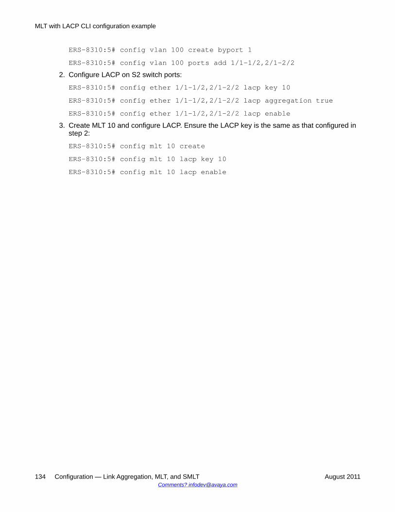
ERS-8310:5# config vlan 100 create byport 1ERS-8310:5# config vlan 100 ports add 1/1-1/2,2/1-2/2
2. Configure LACP on S2 switch ports:
ERS-8310:5# config ether 1/1-1/2,2/1-2/2 lacp key 10ERS-8310:5# config ether 1/1-1/2,2/1-2/2 lacp aggregation trueERS-8310:5# config ether 1/1-1/2,2/1-2/2 lacp enable
3. Create MLT 10 and configure LACP. Ensure the LACP key is the same as that configured instep 2:
ERS-8310:5# config mlt 10 createERS-8310:5# config mlt 10 lacp key 10ERS-8310:5# config mlt 10 lacp enable
MLT with LACP CLI configuration example
134 Configuration — Link Aggregation, MLT, and SMLT August 2011Comments? [email protected]
Chapter 8: SMLT CLI configurationexamples
This chapter provides examples for common Split MultiLink Trunking (SMLT) tasks and includes thecommand line interface (CLI) commands you use to create the sample configurations.
For more configuration examples, see the Technical Configuration Guide for Ethernet Routing Switch 8300VLAN, Spanning Tree, and Link Aggregation using the ACLI. You can find this Technical ConfigurationGuide at www.support.avaya.com under the Data Center Solution or Data Networking Solutionproducts.
Navigation• SMLT triangle configuration example using the CLI on page 135• Single-port SMLT with SLPP configuration example using the CLI on page 138• SMLT configuration example using the CLI on page 141• Square SMLT configuration example using the CLI on page 143• Full mesh SMLT configuration example using the CLI on page 147• SMLT and VRRP configuration example using the CLI on page 150
SMLT triangle configuration example using the CLIThis configuration example shows how to create an SMLT triangle using three Ethernet RoutingSwitch 8300s and a VLAN (VLAN 10), which carries user traffic.
Configuration — Link Aggregation, MLT, and SMLT August 2011 135
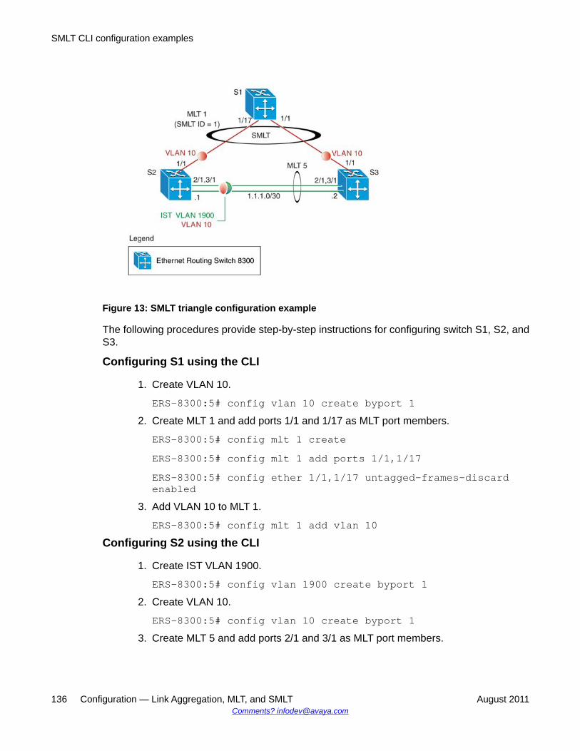
Figure 13: SMLT triangle configuration example
The following procedures provide step-by-step instructions for configuring switch S1, S2, andS3.
Configuring S1 using the CLI
1. Create VLAN 10.
ERS-8300:5# config vlan 10 create byport 12. Create MLT 1 and add ports 1/1 and 1/17 as MLT port members.
ERS-8300:5# config mlt 1 createERS-8300:5# config mlt 1 add ports 1/1,1/17ERS-8300:5# config ether 1/1,1/17 untagged-frames-discardenabled
3. Add VLAN 10 to MLT 1.
ERS-8300:5# config mlt 1 add vlan 10Configuring S2 using the CLI
1. Create IST VLAN 1900.
ERS-8300:5# config vlan 1900 create byport 12. Create VLAN 10.
ERS-8300:5# config vlan 10 create byport 13. Create MLT 5 and add ports 2/1 and 3/1 as MLT port members.
SMLT CLI configuration examples
136 Configuration — Link Aggregation, MLT, and SMLT August 2011Comments? [email protected]
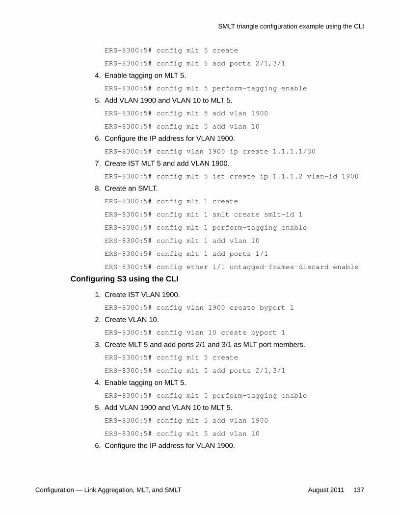
ERS-8300:5# config mlt 5 createERS-8300:5# config mlt 5 add ports 2/1,3/1
4. Enable tagging on MLT 5.
ERS-8300:5# config mlt 5 perform-tagging enable5. Add VLAN 1900 and VLAN 10 to MLT 5.
ERS-8300:5# config mlt 5 add vlan 1900ERS-8300:5# config mlt 5 add vlan 10
6. Configure the IP address for VLAN 1900.
ERS-8300:5# config vlan 1900 ip create 1.1.1.1/307. Create IST MLT 5 and add VLAN 1900.
ERS-8300:5# config mlt 5 ist create ip 1.1.1.2 vlan-id 19008. Create an SMLT.
ERS-8300:5# config mlt 1 createERS-8300:5# config mlt 1 smlt create smlt-id 1ERS-8300:5# config mlt 1 perform-tagging enableERS-8300:5# config mlt 1 add vlan 10ERS-8300:5# config mlt 1 add ports 1/1ERS-8300:5# config ether 1/1 untagged-frames-discard enable
Configuring S3 using the CLI
1. Create IST VLAN 1900.
ERS-8300:5# config vlan 1900 create byport 12. Create VLAN 10.
ERS-8300:5# config vlan 10 create byport 13. Create MLT 5 and add ports 2/1 and 3/1 as MLT port members.
ERS-8300:5# config mlt 5 createERS-8300:5# config mlt 5 add ports 2/1,3/1
4. Enable tagging on MLT 5.
ERS-8300:5# config mlt 5 perform-tagging enable5. Add VLAN 1900 and VLAN 10 to MLT 5.
ERS-8300:5# config mlt 5 add vlan 1900ERS-8300:5# config mlt 5 add vlan 10
6. Configure the IP address for VLAN 1900.
SMLT triangle configuration example using the CLI
Configuration — Link Aggregation, MLT, and SMLT August 2011 137

ERS-8300:5# config vlan 1900 ip create 1.1.1.2/307. Create IST MLT 5 and add VLAN 1900.
ERS-8300:5# config mlt 5 ist create ip 1.1.1.1 vlan-id 19008. Create an SMLT.
ERS-8300:5# config mlt 1 createERS-8300:5# config mlt 1 smlt create smlt-id 1ERS-8300:5# config mlt 1 perform-tagging enableERS-8300:5# config mlt 1 add vlan 10ERS-8300:5# config mlt 1 add ports 1/1ERS-8300:5# config ether 1/1 untagged-frames-discard enable
Single-port SMLT with SLPP configuration example usingthe CLI
The single-port SMLT design is similar to the triangle SMLT design. The difference is that onlya single port from each InterSwitch Trunking (IST) switch goes to the access server.
SMLT CLI configuration examples
138 Configuration — Link Aggregation, MLT, and SMLT August 2011Comments? [email protected]
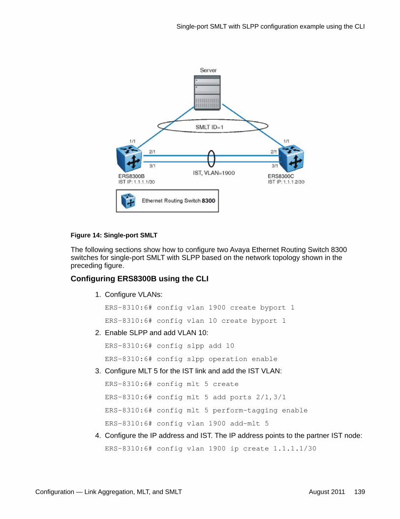
Figure 14: Single-port SMLT
The following sections show how to configure two Avaya Ethernet Routing Switch 8300switches for single-port SMLT with SLPP based on the network topology shown in thepreceding figure.
Configuring ERS8300B using the CLI
1. Configure VLANs:
ERS-8310:6# config vlan 1900 create byport 1ERS-8310:6# config vlan 10 create byport 1
2. Enable SLPP and add VLAN 10:
ERS-8310:6# config slpp add 10ERS-8310:6# config slpp operation enable
3. Configure MLT 5 for the IST link and add the IST VLAN:
ERS-8310:6# config mlt 5 createERS-8310:6# config mlt 5 add ports 2/1,3/1ERS-8310:6# config mlt 5 perform-tagging enableERS-8310:6# config vlan 1900 add-mlt 5
4. Configure the IP address and IST. The IP address points to the partner IST node:
ERS-8310:6# config vlan 1900 ip create 1.1.1.1/30
Single-port SMLT with SLPP configuration example using the CLI
Configuration — Link Aggregation, MLT, and SMLT August 2011 139
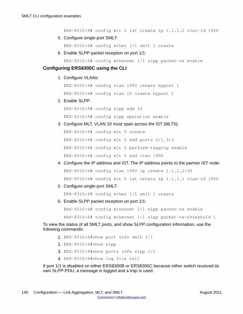
ERS-8310:6# config mlt 5 ist create ip 1.1.1.2 vlan-id 19005. Configure single-port SMLT:
ERS-8310:6# config ether 1/1 smlt 1 create6. Enable SLPP packet reception on port 1/1:
ERS-8310:6# config ethernet 1/1 slpp packet-rx enableConfiguring ERS8300C using the CLI
1. Configure VLANs:
ERS-8310:6# config vlan 1900 create byport 1ERS-8310:6# config vlan 10 create byport 1
2. Enable SLPP:
ERS-8310:6# config slpp add 10ERS-8310:6# config slpp operation enable
3. Configure MLT. VLAN 10 must span across the IST (MLT5):
ERS-8310:6# config mlt 5 createERS-8310:6# config mlt 5 add ports 2/1,3/1ERS-8310:6# config mlt 5 perform-tagging enableERS-8310:6# config mlt 5 add vlan 1900
4. Configure the IP address and IST. The IP address points to the partner IST node:
ERS-8310:6# config vlan 1900 ip create 1.1.1.2/30ERS-8310:6# config mlt 5 ist create ip 1.1.1.1 vlan-id 1900
5. Configure single-port SMLT:
ERS-8310:6# config ether 1/1 smlt 1 create6. Enable SLPP packet reception on port 1/1:
ERS-8310:6# config ethernet 1/1 slpp packet-rx enableERS-8310:6# config ethernet 1/1 slpp packet-rx-threshold 1
To view the status of all SMLT ports, and show SLPP configuration information, use thefollowing commands:
1. ERS-8310:6#show port info smlt 1/12. ERS-8310:6#show slpp3. ERS-8310:6#show ports info slpp 1/14. ERS-8310:6#show log file tail
If port 1/1 is disabled on either ERS8300B or ERS8300C because either switch received itsown SLPP-PDU, a message is logged and a trap is used.
SMLT CLI configuration examples
140 Configuration — Link Aggregation, MLT, and SMLT August 2011Comments? [email protected]
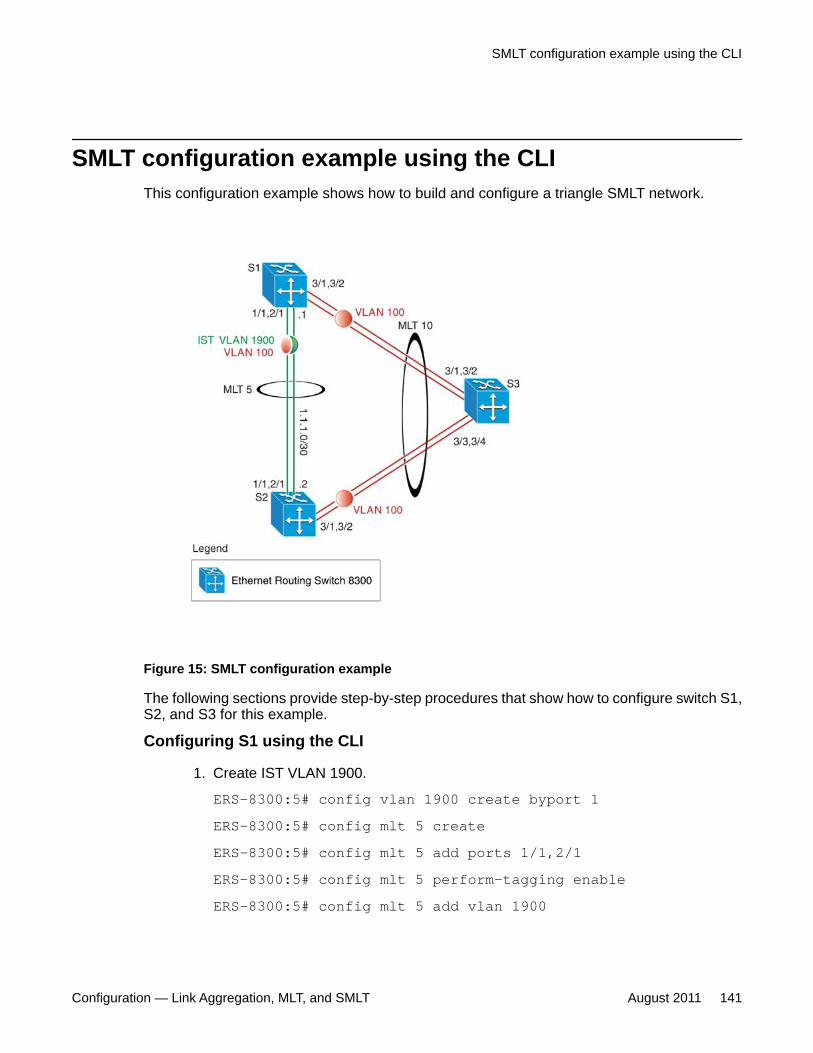
SMLT configuration example using the CLIThis configuration example shows how to build and configure a triangle SMLT network.
Figure 15: SMLT configuration example
The following sections provide step-by-step procedures that show how to configure switch S1,S2, and S3 for this example.
Configuring S1 using the CLI
1. Create IST VLAN 1900.
ERS-8300:5# config vlan 1900 create byport 1ERS-8300:5# config mlt 5 createERS-8300:5# config mlt 5 add ports 1/1,2/1ERS-8300:5# config mlt 5 perform-tagging enableERS-8300:5# config mlt 5 add vlan 1900
SMLT configuration example using the CLI
Configuration — Link Aggregation, MLT, and SMLT August 2011 141
ERS-8300:5# config vlan 1900 ip create 1.1.1.1/30ERS-8300:5# config mlt 5 ist create ip 1.1.1.2 vlan-id 1900
2. Create the SMLT VLAN and add ports.
ERS-8300:5# config vlan 100 create byport 1ERS-8300:5# config vlan 100 ports add 3/1,3/2ERS-8300:5# config vlan 100 add-mlt 5
3. Create SMLT.
Ensure Keys match port and keys are same for both SMLT aggregation switches.
ERS-8300:5# config mlt 10 createERS-8300:5# config mlt 10 smlt create smlt-id 10ERS-8300:5# config mlt 10 perform-tagging enableERS-8300:5# config mlt 10 add vlan 100ERS-8300:5# config ether 3/1,3/2 discard-untagged-framesenable
Configuring S2 using the CLI
1. Create IST VLAN 1900.
ERS-8300:5# config vlan 1900 create byport 1ERS-8300:5# config mlt 5 createERS-8300:5# config mlt 5 add ports 1/1,2/1ERS-8300:5# config mlt 5 perform-tagging enableERS-8300:5# config mlt 5 add vlan 1900ERS-8300:5# config vlan 1900 ip create 1.1.1.2/30ERS-8300:5# config mlt 5 ist create ip 1.1.1.1 vlan-id 1900
2. Create the SMLT VLAN and add ports.
ERS-8300:5# config vlan 100 create byport 1ERS-8300:5# config vlan 100 ports add 3/1,3/2ERS-8300:5# config vlan 100 add-mlt 5
3. Create SMLT.
Ensure Keys match port and keys are same for both SMLT aggregation switches.
ERS-8300:5# config mlt 10 createERS-8300:5# config mlt 10 smlt create smlt-id 10ERS-8300:5# config mlt 10 perform-tagging enable
SMLT CLI configuration examples
142 Configuration — Link Aggregation, MLT, and SMLT August 2011Comments? [email protected]
ERS-8300:5# config mlt 10 add vlan 100ERS-8300:5# config ether 3/1,3/2 untagged-frames-discard<enable|disable>
Configuring S3 using the CLI
1. Create VLAN 100 and add ports.
ERS-8300:5# config vlan 100 create byport 1ERS-8300:5# config vlan 100 ports add 3/1-3/4
2. Create MLT 10.
Ensure Keys match port and keys are same for both SMLT aggregation switches.
ERS-8300:5# config mlt 10 createERS-8300:5# config mlt 10 perform-tagging enableERS-8300:5# config ether 3/1-3/4 untagged-frames-discard<enable|disable>
Square SMLT configuration example using the CLIThe main rule for a square configuration is that the IST pairs, ERS8300A and D, and B and C,each must have matching SMLT IDs. However, these IDs can differ between the two IST pairs.The initial configuration creates the IST links between A and B, and C and D. Note that the ISTIP addresses differ; Avaya recommends that you use a different subnet for the IST IPaddresses between the pairs.
Square SMLT configuration example using the CLI
Configuration — Link Aggregation, MLT, and SMLT August 2011 143

Figure 16: Square SMLT example
Configuring ERS8300B using the CLI
1. Configure VLANs:
ERS-8300:5# config vlan 1900 create byport 1ERS-8300:5# config vlan 10 create byport 1
2. Configure MLT.
VLAN 10 must span across the IST (MLT5):
ERS-8310:5# config mlt 5 createERS-8300:5# config mlt 5 add ports 2/1,3/1ERS-8300:5# config mlt 5 add vlan 1900ERS-8300:5# config mlt 5 add vlan 10
3. Configure the IP address and IST.
The IP address points to the partner IST node:
ERS-8300:5# config vlan 1900 ip create 1.1.1.1/30ERS-8300:5# config mlt 5 ist create ip 1.1.1.1 vlan-id 1900
4. Configure SMLT.
SMLT CLI configuration examples
144 Configuration — Link Aggregation, MLT, and SMLT August 2011Comments? [email protected]
The SMLT ID must be identical for each IST pair:
ERS-8300:5# config mlt 1 createERS-8300:5# config mlt 1 smlt create smlt-id 1ERS-8300:5# config mlt 1 add vlan 10ERS-8300:5# config mlt 1 add ports 1/1
Configuring ERS8300C using the CLI
1. Configure VLANs:
ERS-8300:5# config vlan 1900 create byport 1ERS-8300:5# config vlan 10 create byport 1
2. Configure MLT.
VLAN 10 must span across the IST (MLT5):
ERS-8300:5# config mlt 5 createERS-8300:5# config mlt 5 add ports 2/1,3/1ERS-8300:5# config mlt 5 add vlan 1900ERS-8300:5# config mlt 5 add vlan 10
3. Configure the IP address and IST.
The IP address points to the partner IST node:
ERS-8300:5# config vlan 1900 ip create 1.1.1.2/30ERS-8300:5# config mlt 5 ist create ip 1.1.1.1 vlan-id 1900
4. Configure SMLT.
The SMLT ID must be identical for each SMLT pair:
ERS-8300:5# config mlt 1 createERS-8300:5# config mlt 1 smlt create smlt-id 1ERS-8300:5# config mlt 1 add vlan 10ERS-8300:5# config mlt 1 add ports 1/1
Configuring ERS8300A using the CLI
1. Configure VLANs:
ERS-8300:5# config vlan 1900 create byport 1ERS-8300:5# config vlan 10 create byport 1
2. Configure MLT.
VLAN 10 must span across the IST (MLT5):
Square SMLT configuration example using the CLI
Configuration — Link Aggregation, MLT, and SMLT August 2011 145
ERS-8300:5# config mlt 5 createERS-8300:5# config mlt 5 add ports 2/1,3/1ERS-8300:5# config mlt 5 add vlan 1900ERS-8300:5# config mlt 5 add vlan 10
3. Configure the IP address and IST.
The IP address points to the partner IST node:
ERS-8300:5# config vlan 1900 ip create 2.2.2.2/30ERS-8300:5# config mlt 5 ist create ip 2.2.2.2 vlan-id 1900
4. Configure SMLT.
The SMLT ID must be identical for each IST pair:
ERS-8300:5# config mlt 1 createERS-8300:5# config mlt 1 smlt create smlt-id 1ERS-8300:5# config mlt 1 add vlan 10ERS-8300:5# config mlt 1 add ports 1/1
Configuring ERS8300D using the CLI
1. Configure VLANs:
ERS-8300:5# config vlan 1900 create byport 1ERS-8300:5# config vlan 10 create byport 1
2. Configure MLT.
VLAN 10 must span across the IST (MLT5):
ERS-8300:5# config mlt 5 createERS-8300:5# config mlt 5 add ports 2/1,3/1ERS-8300:5# config mlt 5 add vlan 1900ERS-8300:5# config mlt 5 add vlan 10
3. Configure the IP address and IST.
The IP address points to the partner IST node:
ERS-8300:5# config vlan 1900 ip create 2.2.2.2/30ERS-8300:5# config mlt 5 ist create ip 2.2.2.1 vlan-id 1900
4. Configure SMLT.
The SMLT ID must be identical for each IST pair:
ERS-8300:5# config mlt 1 create
SMLT CLI configuration examples
146 Configuration — Link Aggregation, MLT, and SMLT August 2011Comments? [email protected]
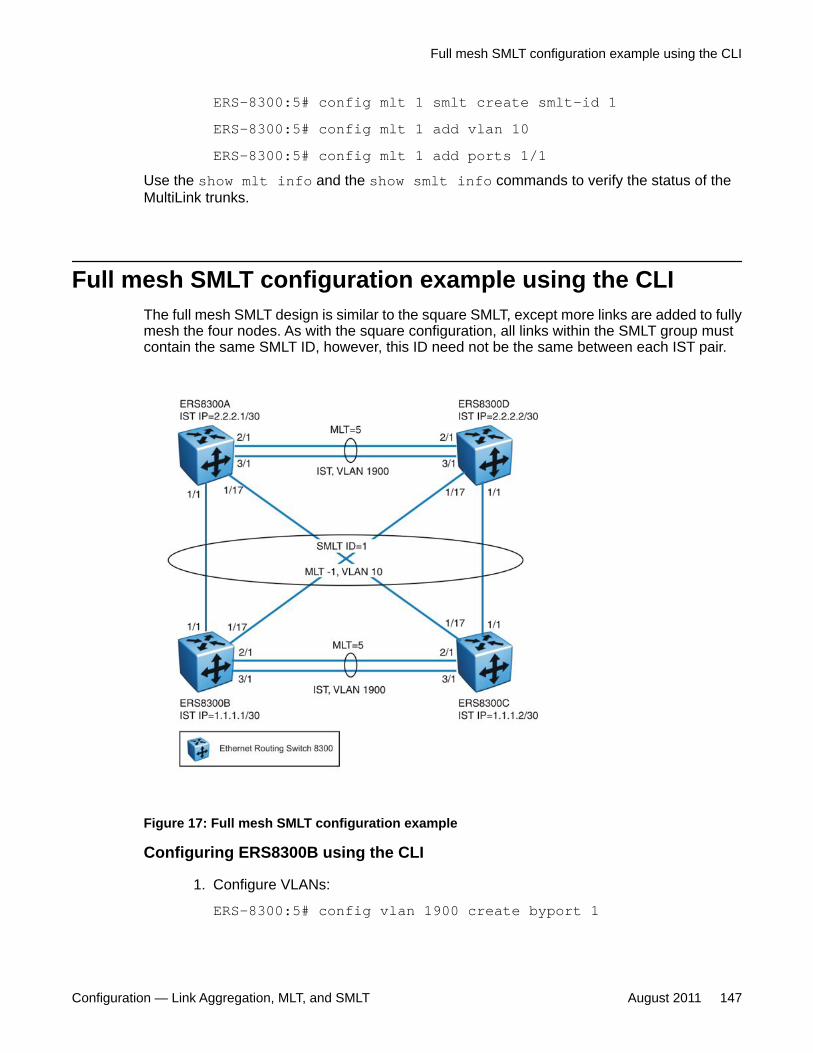
ERS-8300:5# config mlt 1 smlt create smlt-id 1ERS-8300:5# config mlt 1 add vlan 10ERS-8300:5# config mlt 1 add ports 1/1
Use the show mlt info and the show smlt info commands to verify the status of theMultiLink trunks.
Full mesh SMLT configuration example using the CLIThe full mesh SMLT design is similar to the square SMLT, except more links are added to fullymesh the four nodes. As with the square configuration, all links within the SMLT group mustcontain the same SMLT ID, however, this ID need not be the same between each IST pair.
Figure 17: Full mesh SMLT configuration example
Configuring ERS8300B using the CLI
1. Configure VLANs:
ERS-8300:5# config vlan 1900 create byport 1
Full mesh SMLT configuration example using the CLI
Configuration — Link Aggregation, MLT, and SMLT August 2011 147
ERS-8300:5# config vlan 10 create byport 12. Configure MLT.
VLAN 10 must span across the IST (MLT5):
ERS-8300:5# config mlt 5 createERS-8300:5# config mlt 5 add ports 2/1,3/1ERS-8300:5# config mlt 5 add vlan 1900ERS-8300:5# config mlt 5 add vlan 10
3. Configure the IP address and IST.
The IP address points to the partner IST node:
ERS-8300:5# config vlan 1900 ip create 1.1.1.1/30ERS-8300:5# config mlt 5 ist create ip 1.1.1.2 vlan-id 1900
4. Configure SMLT.
The SMLT ID must be identical for each IST pair:
ERS-8300:5# config mlt 1 createERS-8300:5# config mlt 1 smlt create smlt-id 1ERS-8300:5# config mlt 1 add vlan 10ERS-8300:5# config mlt 1 add ports 1/1,1/17
Configuring ERS8300C using the CLI
1. Configure VLANs:
ERS-8300:5# config vlan 1900 create byport 1ERS-8300:5# config vlan 10 create byport 1
2. Configure MLT.
VLAN 10 must span across the IST (MLT5):
ERS-8300:5# config mlt 5 createERS-8300:5# config mlt 5 add ports 2/1,3/1ERS-8300:5# config mlt 5 add vlan 1900ERS-8300:5# config mlt 5 add vlan 10
3. Configure the IP address and IST.
The IP address points to the partner IST node:
ERS-8300:5# config vlan 1900 ip create 1.1.1.2/30
SMLT CLI configuration examples
148 Configuration — Link Aggregation, MLT, and SMLT August 2011Comments? [email protected]
ERS-8300:5# config mlt 5 ist create ip 1.1.1.1 vlan-id 19004. Configure SMLT.
The SMLT ID must be identical for each IST pair:
ERS-8300:5# config mlt 1 createERS-8300:5# config mlt 1 smlt create smlt-id 1ERS-8300:5# config mlt 1 add vlan 10ERS-8300:5# config mlt 1 add ports 1/1,1/17
Configuring ERS8300A using the CLI
1. Configure VLANs:
ERS-8300:5# config vlan 1900 create byport 1ERS-8300:5# config vlan 10 create byport 1
2. Configure MLT.
VLAN 10 must span across the IST (MLT5):
ERS-8300:5# config mlt 5 createERS-8300:5# config mlt 5 add ports 2/1,3/1ERS-8300:5# config mlt 5 add vlan 1900ERS-8300:5# config mlt 5 add vlan 10
3. Configure the IP address and IST.
The IP address points to the partner IST node:
ERS-8300:5# config vlan 1900 ip create 2.2.2.1/30ERS-8300:5# config mlt 5 ist create ip 2.2.2.2 vlan-id 1900
4. Configure SMLT.
The SMLT ID must be identical for each IST pair:
ERS-8300:5# config mlt 1 createERS-8300:5# config mlt 1 smlt create smlt-id 1ERS-8300:5# config mlt 1 add vlan 10ERS-8300:5# config mlt 1 add ports 1/1,1/17
Configuring ERS8300D using the CLI
1. Configure VLANs:
ERS-8300:5# config vlan 1900 create byport 1
Full mesh SMLT configuration example using the CLI
Configuration — Link Aggregation, MLT, and SMLT August 2011 149
ERS-8300:5# config vlan 10 create byport 12. Configure MLT.
VLAN 10 must span across the IST (MLT5):
ERS-8300:5# config mlt 5 createERS-8300:5# config mlt 5 add ports 2/1,3/1ERS-8300:5# config mlt 5 add vlan 1900ERS-8300:5# config mlt 5 add vlan 10
3. Configure the IP address and IST.
The IP address points to the partner IST node:
ERS-8300:5# config vlan 1900 ip create 2.2.2.2/30ERS-8300:5# config mlt 5 ist create ip 2.2.2.1 vlan-id 1900
4. Configure SMLT.
The SMLT ID must be identical for each IST pair:
ERS-8300:5# config mlt 1 createERS-8300:5# config mlt 1 smlt create smlt-id 1ERS-8300:5# config mlt 1 add vlan 10ERS-8300:5# config mlt 1 add ports 1/1,1/17
Use the show mlt info and the show smlt info commands to verify the status of theMultiLink trunks.
SMLT and VRRP configuration example using the CLIIn cases where the Ethernet Routing Switch provides the next-hop gateway and is in the VirtualRouter Redundancy Protocol (VRRP) mode, the Ethernet Routing Switch can provideadditional VRRP benefits. In the following figure, ERS8300A acts solely as a Layer 2 switch,with a single VLAN 10 configured. The server in this example has a next-hop gatewayconfigured for the VRRP IP.
SMLT CLI configuration examples
150 Configuration — Link Aggregation, MLT, and SMLT August 2011Comments? [email protected]
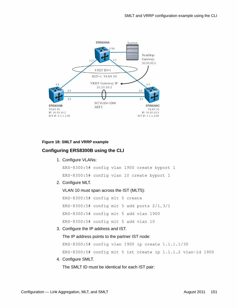
Figure 18: SMLT and VRRP example
Configuring ERS8300B using the CLI
1. Configure VLANs:
ERS-8300:5# config vlan 1900 create byport 1ERS-8300:5# config vlan 10 create byport 1
2. Configure MLT.
VLAN 10 must span across the IST (MLT5):
ERS-8300:5# config mlt 5 createERS-8300:5# config mlt 5 add ports 2/1,3/1ERS-8300:5# config mlt 5 add vlan 1900ERS-8300:5# config mlt 5 add vlan 10
3. Configure the IP address and IST.
The IP address points to the partner IST node:
ERS-8300:5# config vlan 1900 ip create 1.1.1.1/30ERS-8300:5# config mlt 5 ist create ip 1.1.1.2 vlan-id 1900
4. Configure SMLT.
The SMLT ID must be identical for each IST pair:
SMLT and VRRP configuration example using the CLI
Configuration — Link Aggregation, MLT, and SMLT August 2011 151
ERS-8300:5# config mlt 1 createERS-8300:5# config mlt 1 smlt create smlt-id 1ERS-8300:5# config mlt 1 add vlan 10ERS-8300:5# config mlt 1 add ports 1/1,1/17
5. Configure VRRP.
These commands add the VRRP virtual IP address of 10.10.10.1 to VLAN 10 withBackupMaster enabled so that both ERS8300B and ERS8300C can respond toARP.
ERS-8300:5# config vlan 10 ip create 10.10.10.2/24ERS-8300:5# config vlan 10 ip vrrp 1 address 10.10.10.1ERS-8300:5# config vlan 10 ip vrrp 1 backup-master enableERS8300:5# config vlan 10 ip vrrp 1 holddown-timer 60ERS-8300:5# config vlan 10 ip vrrp 1 enable
Configuring ERS8300C using the CLI
1. Configure VLANs:
ERS-8300:5# config vlan 1900 create byport 1ERS-8300:5# config vlan 10 create byport 1
2. Configure MLT.
VLAN 10 must span across the IST (MLT5):
ERS-8300:5# config mlt 5 createERS-8300:5# config mlt 5 add ports 2/1,3/1ERS-8300:5# config mlt 5 add vlan 1900ERS-8300:5# config mlt 5 add vlan 10
3. Configure the IP address and IST.
The IP address points to the partner IST node:
ERS-8300:5# config vlan 1900 ip create 1.1.1.2/30ERS-8300:5# config mlt 5 ist create ip 1.1.1.1 vlan-id 1900
4. Configure SMLT.
The SMLT ID must be identical for each IST pair:
ERS-8300:5# config mlt 1 createERS-8300:5# config mlt 1 smlt create smlt-id 1ERS-8300:5# config mlt 1 add vlan 10
SMLT CLI configuration examples
152 Configuration — Link Aggregation, MLT, and SMLT August 2011Comments? [email protected]
ERS-8300:5# config mlt 1 add ports 1/15. Configure VRRP.
These commands add the VRRP virtual IP address of 10.10.10.1 to VLAN 10 withBackupMaster enabled so that both ERS8300B and ERS8300C can respond toARP.
ERS-8300:5# config vlan 10 ip create 10.10.10.3/24ERS-8300:5# config vlan 10 ip vrrp 1 address 10.10.10.1ERS-8300:5# config vlan 10 ip vrrp 1 backup-master enableERS8300:5# config vlan 10 ip vrrp 1 holddown-timer 65ERS-8300:5# config vlan 10 ip vrrp 1 enable
Configuring ERS8300A using the CLI
Configure VLANs:
ERS-8300:5# config vlan 10 create byport 1ERS-8300:5# config mlt 1 createERS-8300:5# config mlt 1 add ports 1/1,1/17ERS-8300:5# config mlt 1 add vlan 10
You can view the status of VRRP using the command show ip vrrp info.
SMLT and VRRP configuration example using the CLI
Configuration — Link Aggregation, MLT, and SMLT August 2011 153

SMLT CLI configuration examples
154 Configuration — Link Aggregation, MLT, and SMLT August 2011Comments? [email protected]
Chapter 9: SMLT ACLI configurationexamples
This chapter provides examples for common Split MultiLink Trunking (SMLT) tasks and includes the Avayacommand line interface (ACLI) commands you use to create the sample configurations.
For more configuration examples, see the Technical Configuration Guide for Ethernet Routing Switch 8300VLAN, Spanning Tree, and Link Aggregation using the ACLI. You can find this Technical ConfigurationGuide at www.support.avaya.com under the Data Center Solution or Data Networking Solutionproducts.
Navigation• Single-port SMLT triangle configuration example using the ACLI on page 155• Single-port SMLT with SLPP configuration example using the ACLI on page 158• SMLT configuration example using the ACLI on page 161• Square SMLT configuration example using the ACLI on page 165• Full mesh SMLT configuration example using the ACLI on page 169• SMLT and VRRP configuration example using the ACLI on page 173
Single-port SMLT triangle configuration example using theACLI
This configuration example shows how to create a single-port SMLT triangle using three 8300Series switches and a VLAN (VLAN 10), which carries user traffic.
Configuration — Link Aggregation, MLT, and SMLT August 2011 155

Figure 19: Single-port SMLT triangle configuration example
The following procedures provide step-by-step instructions for configuring switch S1, S2, andS3 for this example.
Configuring S2 using the ACLI
1. Create IST VLAN 1900:
ERS-8300:5(config)# vlan create 1900 type port 12. Create VLAN 10:
ERS-8300:5(config)# vlan create 10 type port 13. Create MLT 5 and add ports 2/1 and 3/1 as MLT port members:
ERS-8300:5(config)#mlt 5 createERS-8300:5(config)#mlt 5 member 2/1,3/1
4. Enable tagging on MLT 5:
ERS-8300:5(config)# interface mlt 5ERS-8300:5(config-mlt)# perform-tagging enableERS-8300:5(config-mlt)# end
5. Add VLAN 1900 and VLAN 10 to MLT 5:
ERS-8300:5(config)# mlt 5 add-vlan 1900ERS-8300:5(config)# mlt 5 add-vlan 10
6. Configure a VLAN IP for VLAN 1900:
SMLT ACLI configuration examples
156 Configuration — Link Aggregation, MLT, and SMLT August 2011Comments? [email protected]
ERS-8300:5(config)# interface vlan 1900ERS-8300:5(config-if)# ip address 1.1.1.1 255.255.255.252ERS-8300:5(config-if)# end
7. Create IST MLT 5 and add VLAN 1900:
ERS--8310:5(config)# interface mlt 5ERS-8300:5(config-mlt)# ist ip 1.1.1.2 vlan 1900ERS-8300:5(config-mlt)# ist enableERS-8300:5(config-mlt)# end
8. Create a single-port SMLT:
ERS-8300:5(config)# vlan members add 10 1/1ERS-8300:5(config)# interface fastethernet 1/1ERS-8300:5(config-if)# smlt 1ERS-8300:5(config-if)# untagged-frames-discard port 1/1ERS-8300:5(config-if)# encapsulation dot1q port 1/1ERS-8300:5(config-if)# end
Configuring S3 using the ACLI
1. Create IST VLAN 1900:
ERS-8300:5(config)# vlan create 1900 type port 12. Create VLAN 10:
ERS-8300:5(config)# vlan create 10 type port 13. Create MLT 5 and add ports 2/1 and 3/1 as MLT port members:
ERS-8300:5(config)# mlt 5 createERS-8300:5(config)# mlt 5 member 2/1,3/1
4. Enable tagging on MLT 5:
ERS-8300:5(config)# interface mlt 5ERS-8300:5(config-mlt)# perform-tagging enableERS-8300:5(config-mlt)# end
5. Add VLAN 1900 and VLAN 10 to MLT 5:
ERS-8300:5(config)# mlt 5 add-vlan 1900ERS-8300:5(config)# mlt 5 add-vlan 10
6. Configure a VLAN IP for VLAN 1900:
Single-port SMLT triangle configuration example using the ACLI
Configuration — Link Aggregation, MLT, and SMLT August 2011 157
ERS-8300:5(config)# interface vlan 1900ERS-8300:5(config-if)# ip address 1.1.1.2 255.255.255.252ERS-8300:5(config-if)# end
7. Create IST MLT 5 and add VLAN 1900:
ERS--8310:5(config)# interface mlt 5ERS-8300:5(config-mlt)# ist ip 1.1.1.1 vlan 1900ERS-8300:5(config-mlt)# ist enableERS-8300:5(config-mlt)# end
8. Create a single-port SMLT:
ERS-8300:5(config)# vlan members add 10 1/1ERS-8300:5(config)# interface fastethernet 1/1ERS-8300:5(config-if)# smlt 1ERS-8300:5(config-if)# untagged-frames-discard port 1/1ERS-8300:5(config-if)# encapsulation dot1q port 1/1ERS-8300:5(config-if)# end
Configuring S1 using the ACLI
1. Create VLAN 10:
ERS-8300:5(config)# vlan create 10 type port 12. Create MLT 1 and add ports 1/1 and 1/17 as MLT port members:
ERS-8300:5(config)# mlt 1 createERS-8300:5(config)# mlt 1 member 1/1,1/17ERS-8300:5(config)# interface fast 1/1,1/17ERS-8300:5(config-if)# untagged-frames-discard port 1/1,1/17
3. Add VLAN 10 to MLT 1:
ERS-8300:5(config)# mlt 1 add-vlan 10
Single-port SMLT with SLPP configuration example usingthe ACLI
The single-port Split MultiLink Trunking (SMLT) design is similar to the triangle SMLT design.The difference is that only a single port from each InterSwitch Trunking (IST) switch goes tothe access server. The following figure shows the network topology.
SMLT ACLI configuration examples
158 Configuration — Link Aggregation, MLT, and SMLT August 2011Comments? [email protected]
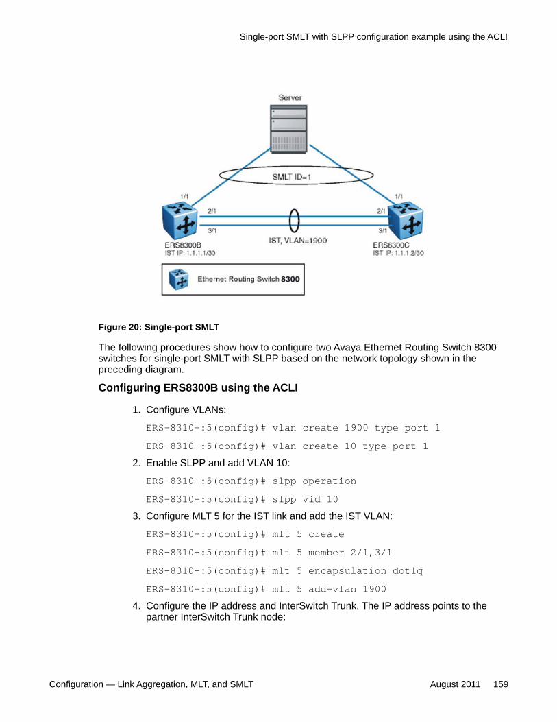
Figure 20: Single-port SMLT
The following procedures show how to configure two Avaya Ethernet Routing Switch 8300switches for single-port SMLT with SLPP based on the network topology shown in thepreceding diagram.
Configuring ERS8300B using the ACLI
1. Configure VLANs:
ERS-8310-:5(config)# vlan create 1900 type port 1ERS-8310-:5(config)# vlan create 10 type port 1
2. Enable SLPP and add VLAN 10:
ERS-8310-:5(config)# slpp operationERS-8310-:5(config)# slpp vid 10
3. Configure MLT 5 for the IST link and add the IST VLAN:
ERS-8310-:5(config)# mlt 5 createERS-8310-:5(config)# mlt 5 member 2/1,3/1ERS-8310-:5(config)# mlt 5 encapsulation dot1qERS-8310-:5(config)# mlt 5 add-vlan 1900
4. Configure the IP address and InterSwitch Trunk. The IP address points to thepartner InterSwitch Trunk node:
Single-port SMLT with SLPP configuration example using the ACLI
Configuration — Link Aggregation, MLT, and SMLT August 2011 159

ERS-8310-:5(config)# interface vlan 1900ERS-8310-:5(config-if)# ip address 1.1.1.1 255.255.255.0ERS-8310-:5(config-if)# interface mlt 5ERS-8310-:5(config-mlt)# ist ip 1.1.1.2 vlan 1900ERS-8310-:5(config-mlt)# end
5. Configure single-port SMLT:
ERS-8310-:5(config)# vlan members add 10 1/1ERS-8310-:5(config)# interface fastethernet 1/1ERS-8310-:5(config-if)# smlt 1
6. Enable SLPP packet reception on port 1/1:
ERS-8310-:5(config-if)# slpp packet-rxERS-8310-:5(config-if)# end
Configuring ERS8300C using the ACLI
1. Configure VLANs:
ERS-8310-:5(config)# vlan create 1900 type port 1ERS-8310-:5(config)# vlan create 10 type port 1
2. Enable SLPP and add VLAN 10:
ERS-8310-:5(config)# slpp operationERS-8310-:5(config)# slpp vid 10
3. Configure MLT 5 used for the IST link and add the IST VLAN:
ERS-8310-:5(config)# mlt 5 createERS-8310-:5(config)# mlt 5 member 2/1,3/1ERS-8310-:5(config)# mlt 5 encapsulation dot1qERS-8310-:5(config)# mlt 5 add-vlan 1900
4. Configure the IP address and InterSwitch Trunk. The IP address points to thepartner InterSwitch Trunk node:
ERS-8310-:5(config)# interface vlan 1900ERS-8310-:5(config-if)# ip address 1.1.1.2 255.255.255.0ERS-8310-:5(config-if)# interface mlt 5ERS-8310-:5(config-mlt)# ist ip 1.1.1.1 vlan 1900ERS-8310-:5(config-mlt)# end
5. Configure single-port SMLT:
SMLT ACLI configuration examples
160 Configuration — Link Aggregation, MLT, and SMLT August 2011Comments? [email protected]
ERS-8310-:5(config)# vlan members add 10 1/1ERS-8310-:5(config)# interface fastethernet 1/1ERS-8310-:5(config-if)# smlt 1
6. Enable SLPP packet reception on port 1/1:
ERS-8310-:5(config-if)# slpp packet-rxERS-8310-:5(config-if)# end
To view the status of all SMLT ports and show SLPP configuration information, use the followingcommands:
1. ERS-8310-:5(config)# show smlt fastethernet 1/12. ERS-8310-:5(config)# show slpp3. ERS-8310-:5(config)# show log file tail
If port 1/1 is disabled on either ERS8300B or ERS8300C because either switch received itsown SLPP-PDU, a message is logged and a trap is used.
SMLT configuration example using the ACLIThis configuration example shows how to build and configure a triangle SMLT network.
SMLT configuration example using the ACLI
Configuration — Link Aggregation, MLT, and SMLT August 2011 161
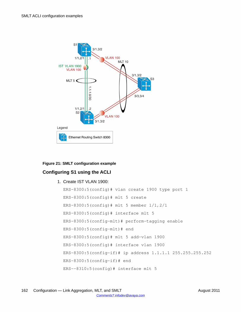
Figure 21: SMLT configuration example
Configuring S1 using the ACLI
1. Create IST VLAN 1900:
ERS-8300:5(config)# vlan create 1900 type port 1ERS-8300:5(config)# mlt 5 createERS-8300:5(config)# mlt 5 member 1/1,2/1ERS-8300:5(config)# interface mlt 5ERS-8300:5(config-mlt)# perform-tagging enableERS-8300:5(config-mlt)# endERS-8300:5(config)# mlt 5 add-vlan 1900ERS-8300:5(config)# interface vlan 1900ERS-8300:5(config-if)# ip address 1.1.1.1 255.255.255.252ERS-8300:5(config-if)# endERS--8310:5(config)# interface mlt 5
SMLT ACLI configuration examples
162 Configuration — Link Aggregation, MLT, and SMLT August 2011Comments? [email protected]
ERS-8300:5(config-mlt)# ist ip 1.1.1.2 vlan 1900ERS-8300:5(config-mlt)# ist enable
2. Create the SMLT VLAN and add IST:
ERS-8300:5(config)# vlan create 100 type port 1ERS-8300:5(config)# vlan add-mlt 100 5
3. Create SMLT:
Ensure Keys match port and keys are same for both SMLT aggregation switches.
ERS-8300:5(config)# mlt 10 createERS-8300:5(config)# mlt 10 member 3/1,3/2ERS-8300:5(config)# interface mlt 10ERS-8300:5(config-mlt)# smlt 10ERS-8300:5(config-mlt)# perform-tagging enableERS-8300:5(config-mlt)# endERS-8300:5(config)# mlt 10 add-vlan 100ERS-8300:5(config)# interface fastethernet 3/1,3/2ERS-8300:5(config-if)# untagged-frames-discard port 3/1,3/2
Configuring S2 using the ACLI
1. Create IST VLAN 1900:
ERS-8300:5(config)# vlan create 1900 type port 1ERS-8300:5(config)# mlt 5 createERS-8300:5(config)# mlt 5 member 1/1,2/1ERS-8300:5(config)# interface mlt 5ERS-8300:5(config-mlt)# perform-tagging enableERS-8300:5(config-mlt)# endERS-8300:5(config)# mlt 5 add-vlan 1900ERS-8300:5(config)# interface vlan 1900ERS-8300:5(config-if)# ip address 1.1.1.2 255.255.255.252ERS-8300:5(config-if)# endERS--8310:5(config)# interface mlt 5ERS-8300:5(config-mlt)# ist ip 1.1.1.1 vlan 1900
SMLT configuration example using the ACLI
Configuration — Link Aggregation, MLT, and SMLT August 2011 163
ERS-8300:5(config-mlt)# ist enable2. Create the SMLT VLAN and add IST:
ERS-8300:5(config)# vlan create 100 type port 1ERS-8300:5(config)# vlan add-mlt 100 5
3. Create SMLT:
Ensure Keys match port and keys are same for both SMLT aggregation switches.
ERS-8300:5(config)# mlt 10 createERS-8300:5(config)# mlt 10 member 3/1,3/2ERS-8300:5(config)# interface mlt 10ERS-8300:5(config-mlt)# smlt 10ERS-8300:5(config-mlt)# perform-tagging enableERS-8300:5(config-mlt)# endERS-8300:5(config)# mlt 10 add-vlan 100ERS-8300:5(config)# interface fast 3/1,3/2ERS-8300:5(config-if)# untagged-frames-discard port 3/1,3/2
Configuring S3 using the ACLI
1. Create VLAN 100 and add ports:
ERS-8300:5(config)# vlan create 100 type port 1ERS-8300:5(config)# vlan members 100 3/1-3/4
2. Create MLT 10:
Ensure Keys match port and keys are same for both SMLT aggregation switches.
ERS-8300:5(config)# mlt 10 createERS-8300:5(config)# mlt 10 member 3/1-3/4ERS-8300:5(config)# mlt 10 add-vlan 100ERS-8300:5(config)# interface mlt 10ERS-8300:5(config-mlt)# perform-tagging enableERS-8300:5(config-mlt)# endERS-8300:5(config)# interface fastethernet 3/1-3/4ERS-8300:5(config-if)# untagged-frames-discard port 3/1-3/4
SMLT ACLI configuration examples
164 Configuration — Link Aggregation, MLT, and SMLT August 2011Comments? [email protected]
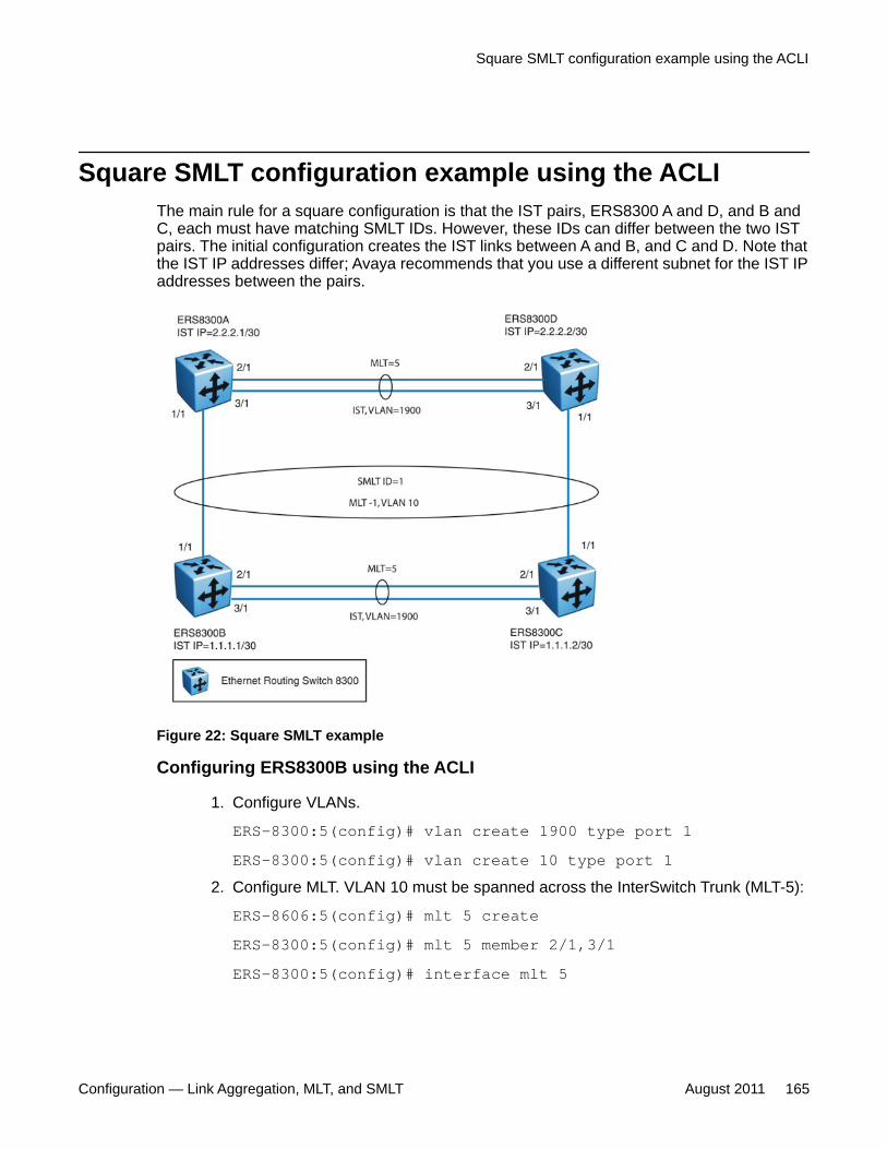
Square SMLT configuration example using the ACLIThe main rule for a square configuration is that the IST pairs, ERS8300 A and D, and B andC, each must have matching SMLT IDs. However, these IDs can differ between the two ISTpairs. The initial configuration creates the IST links between A and B, and C and D. Note thatthe IST IP addresses differ; Avaya recommends that you use a different subnet for the IST IPaddresses between the pairs.
Figure 22: Square SMLT example
Configuring ERS8300B using the ACLI
1. Configure VLANs.
ERS-8300:5(config)# vlan create 1900 type port 1ERS-8300:5(config)# vlan create 10 type port 1
2. Configure MLT. VLAN 10 must be spanned across the InterSwitch Trunk (MLT-5):
ERS-8606:5(config)# mlt 5 createERS-8300:5(config)# mlt 5 member 2/1,3/1ERS-8300:5(config)# interface mlt 5
Square SMLT configuration example using the ACLI
Configuration — Link Aggregation, MLT, and SMLT August 2011 165
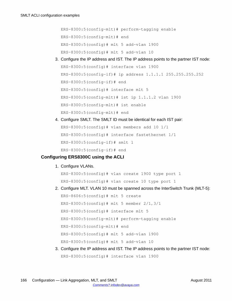
ERS-8300:5(config-mlt)# perform-tagging enableERS-8300:5(config-mlt)# endERS-8300:5(config)# mlt 5 add-vlan 1900ERS-8300:5(config)# mlt 5 add-vlan 10
3. Configure the IP address and IST. The IP address points to the partner IST node:
ERS-8300:5(config)# interface vlan 1900ERS-8300:5(config-if)# ip address 1.1.1.1 255.255.255.252ERS-8300:5(config-if)# endERS-8300:5(config)# interface mlt 5ERS-8300:5(config-mlt)# ist ip 1.1.1.2 vlan 1900ERS-8300:5(config-mlt)# ist enableERS-8300:5(config-mlt)# end
4. Configure SMLT. The SMLT ID must be identical for each IST pair:
ERS-8300:5(config)# vlan members add 10 1/1ERS-8300:5(config)# interface fastethernet 1/1ERS-8300:5(config-if)# smlt 1ERS-8300:5(config-if)# end
Configuring ERS8300C using the ACLI
1. Configure VLANs.
ERS-8300:5(config)# vlan create 1900 type port 1ERS-8300:5(config)# vlan create 10 type port 1
2. Configure MLT. VLAN 10 must be spanned across the InterSwitch Trunk (MLT-5):
ERS-8606:5(config)# mlt 5 createERS-8300:5(config)# mlt 5 member 2/1,3/1ERS-8300:5(config)# interface mlt 5ERS-8300:5(config-mlt)# perform-tagging enableERS-8300:5(config-mlt)# endERS-8300:5(config)# mlt 5 add-vlan 1900ERS-8300:5(config)# mlt 5 add-vlan 10
3. Configure the IP address and IST. The IP address points to the partner IST node:
ERS-8300:5(config)# interface vlan 1900
SMLT ACLI configuration examples
166 Configuration — Link Aggregation, MLT, and SMLT August 2011Comments? [email protected]

ERS-8300:5(config-if)# ip address 1.1.1.2 255.255.255.252ERS-8300:5(config-if)# endERS-8300:5(config)# interface mlt 5ERS-8300:5(config-mlt)# ist ip 1.1.1.1 vlan 1900ERS-8300:5(config-mlt)# ist enableERS-8300:5(config-mlt)# end
4. Configure SMLT. The SMLT ID must be identical for each IST pair:
ERS-8300:5(config)# vlan members add 10 1/1ERS-8300:5(config)# interface fastethernet 1/1ERS-8300:5(config-if)# smlt 1ERS-8300:5(config-if)# end
Configuring ERS8300A using the ACLI
1. Configure VLANs.
ERS-8300:5(config)# vlan create 1900 type port 1ERS-8300:5(config)# vlan create 10 type port 1
2. Configure MLT. VLAN 10 must be spanned across the InterSwitch Trunk (MLT-5):
ERS-8606:5(config)# mlt 5 createERS-8300:5(config)# mlt 5 member 2/1,3/1ERS-8300:5(config)# interface mlt 5ERS-8300:5(config-mlt)# perform-tagging enableERS-8300:5(config-mlt)# endERS-8300:5(config)# mlt 5 add-vlan 1900ERS-8300:5(config)# mlt 5 add-vlan 10
3. Configure the IP address and IST. The IP address points to the partner IST node:
ERS-8300:5(config)# interface vlan 1900ERS-8300:5(config-if)# ip address 2.2.2.1 255.255.255.252ERS-8300:5(config-if)# endERS-8300:5(config)# interface mlt 5ERS-8300:5(config-mlt)# ist ip 2.2.2.2 vlan 1900ERS-8300:5(config-mlt)# ist enable
Square SMLT configuration example using the ACLI
Configuration — Link Aggregation, MLT, and SMLT August 2011 167
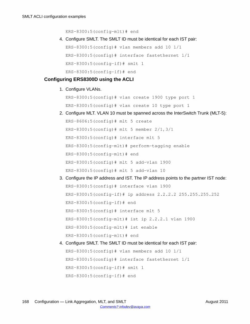
ERS-8300:5(config-mlt)# end4. Configure SMLT. The SMLT ID must be identical for each IST pair:
ERS-8300:5(config)# vlan members add 10 1/1ERS-8300:5(config)# interface fastethernet 1/1ERS-8300:5(config-if)# smlt 1ERS-8300:5(config-if)# end
Configuring ERS8300D using the ACLI
1. Configure VLANs.
ERS-8300:5(config)# vlan create 1900 type port 1ERS-8300:5(config)# vlan create 10 type port 1
2. Configure MLT. VLAN 10 must be spanned across the InterSwitch Trunk (MLT-5):
ERS-8606:5(config)# mlt 5 createERS-8300:5(config)# mlt 5 member 2/1,3/1ERS-8300:5(config)# interface mlt 5ERS-8300:5(config-mlt)# perform-tagging enableERS-8300:5(config-mlt)# endERS-8300:5(config)# mlt 5 add-vlan 1900ERS-8300:5(config)# mlt 5 add-vlan 10
3. Configure the IP address and IST. The IP address points to the partner IST node:
ERS-8300:5(config)# interface vlan 1900ERS-8300:5(config-if)# ip address 2.2.2.2 255.255.255.252ERS-8300:5(config-if)# endERS-8300:5(config)# interface mlt 5ERS-8300:5(config-mlt)# ist ip 2.2.2.1 vlan 1900ERS-8300:5(config-mlt)# ist enableERS-8300:5(config-mlt)# end
4. Configure SMLT. The SMLT ID must be identical for each IST pair:
ERS-8300:5(config)# vlan members add 10 1/1ERS-8300:5(config)# interface fastethernet 1/1ERS-8300:5(config-if)# smlt 1ERS-8300:5(config-if)# end
SMLT ACLI configuration examples
168 Configuration — Link Aggregation, MLT, and SMLT August 2011Comments? [email protected]
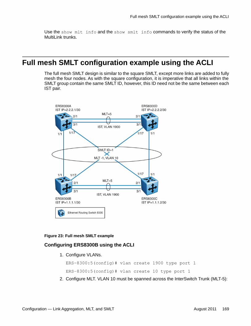
Use the show mlt info and the show smlt info commands to verify the status of theMultiLink trunks.
Full mesh SMLT configuration example using the ACLIThe full mesh SMLT design is similar to the square SMLT, except more links are added to fullymesh the four nodes. As with the square configuration, it is imperative that all links within theSMLT group contain the same SMLT ID, however, this ID need not be the same between eachIST pair.
Figure 23: Full mesh SMLT example
Configuring ERS8300B using the ACLI
1. Configure VLANs.
ERS-8300:5(config)# vlan create 1900 type port 1ERS-8300:5(config)# vlan create 10 type port 1
2. Configure MLT. VLAN 10 must be spanned across the InterSwitch Trunk (MLT-5):
Full mesh SMLT configuration example using the ACLI
Configuration — Link Aggregation, MLT, and SMLT August 2011 169

ERS-8606:5(config)# mlt 5 createERS-8300:5(config)# mlt 5 member 2/1,3/1ERS-8300:5(config)# interface mlt 5ERS-8300:5(config-mlt)# perform-tagging enableERS-8300:5(config-mlt)# endERS-8300:5(config)# mlt 5 add-vlan 1900ERS-8300:5(config)# mlt 5 add-vlan 10
3. Configure the IP address and IST. The IP address points to the partner IST node:
ERS-8300:5(config)# interface vlan 1900ERS-8300:5(config-if)# ip address 1.1.1.1 255.255.255.252ERS-8300:5(config-if)# endERS-8300:5(config)# interface mlt 5ERS-8300:5(config-mlt)# ist ip 1.1.1.2 vlan 1900ERS-8300:5(config-mlt)# ist enableERS-8300:5(config-mlt)# end
4. Configure SMLT. The SMLT ID must be identical for each IST pair:
ERS-8606:5(config)# mlt 1 createERS-8300:5(config)# mlt 1 member 1/1,1/17ERS-8300:5(config)# mlt 1 add-vlan 10ERS-8300:5(config)# interface mlt 1ERS-8300:5(config-mlt)# smlt 1ERS-8300:5(config-mlt)# end
Configuring ERS8300C using the ACLI
1. Configure VLANs.
ERS-8300:5(config)# vlan create 1900 type port 1ERS-8300:5(config)# vlan create 10 type port 1
2. Configure MLT. VLAN 10 must be spanned across the InterSwitch Trunk (MLT-5):
ERS-8606:5(config)# mlt 5 createERS-8300:5(config)# mlt 5 member 2/1,3/1ERS-8300:5(config)# interface mlt 5ERS-8300:5(config-mlt)# perform-tagging enable
SMLT ACLI configuration examples
170 Configuration — Link Aggregation, MLT, and SMLT August 2011Comments? [email protected]
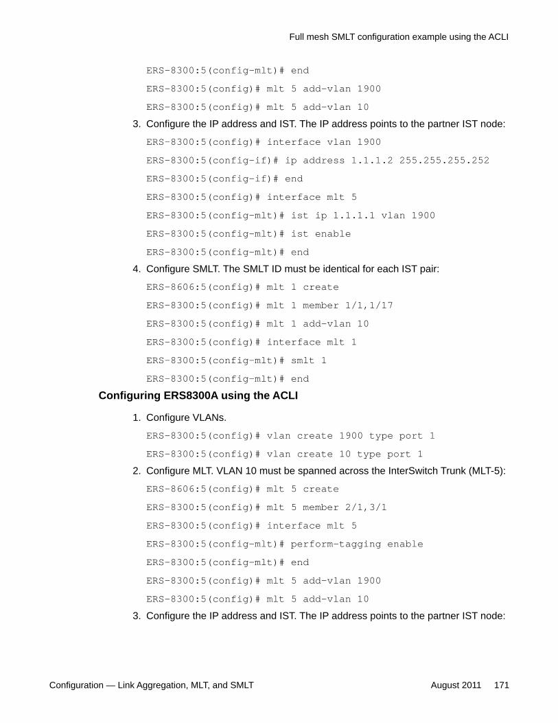
ERS-8300:5(config-mlt)# endERS-8300:5(config)# mlt 5 add-vlan 1900ERS-8300:5(config)# mlt 5 add-vlan 10
3. Configure the IP address and IST. The IP address points to the partner IST node:
ERS-8300:5(config)# interface vlan 1900ERS-8300:5(config-if)# ip address 1.1.1.2 255.255.255.252ERS-8300:5(config-if)# endERS-8300:5(config)# interface mlt 5ERS-8300:5(config-mlt)# ist ip 1.1.1.1 vlan 1900ERS-8300:5(config-mlt)# ist enableERS-8300:5(config-mlt)# end
4. Configure SMLT. The SMLT ID must be identical for each IST pair:
ERS-8606:5(config)# mlt 1 createERS-8300:5(config)# mlt 1 member 1/1,1/17ERS-8300:5(config)# mlt 1 add-vlan 10ERS-8300:5(config)# interface mlt 1ERS-8300:5(config-mlt)# smlt 1ERS-8300:5(config-mlt)# end
Configuring ERS8300A using the ACLI
1. Configure VLANs.
ERS-8300:5(config)# vlan create 1900 type port 1ERS-8300:5(config)# vlan create 10 type port 1
2. Configure MLT. VLAN 10 must be spanned across the InterSwitch Trunk (MLT-5):
ERS-8606:5(config)# mlt 5 createERS-8300:5(config)# mlt 5 member 2/1,3/1ERS-8300:5(config)# interface mlt 5ERS-8300:5(config-mlt)# perform-tagging enableERS-8300:5(config-mlt)# endERS-8300:5(config)# mlt 5 add-vlan 1900ERS-8300:5(config)# mlt 5 add-vlan 10
3. Configure the IP address and IST. The IP address points to the partner IST node:
Full mesh SMLT configuration example using the ACLI
Configuration — Link Aggregation, MLT, and SMLT August 2011 171
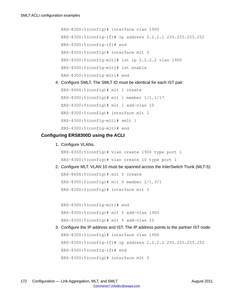
ERS-8300:5(config)# interface vlan 1900ERS-8300:5(config-if)# ip address 2.2.2.1 255.255.255.252ERS-8300:5(config-if)# endERS-8300:5(config)# interface mlt 5ERS-8300:5(config-mlt)# ist ip 2.2.2.2 vlan 1900ERS-8300:5(config-mlt)# ist enableERS-8300:5(config-mlt)# end
4. Configure SMLT. The SMLT ID must be identical for each IST pair:
ERS-8606:5(config)# mlt 1 createERS-8300:5(config)# mlt 1 member 1/1,1/17ERS-8300:5(config)# mlt 1 add-vlan 10ERS-8300:5(config)# interface mlt 1ERS-8300:5(config-mlt)# smlt 1ERS-8300:5(config-mlt)# end
Configuring ERS8300D using the ACLI
1. Configure VLANs.
ERS-8300:5(config)# vlan create 1900 type port 1ERS-8300:5(config)# vlan create 10 type port 1
2. Configure MLT. VLAN 10 must be spanned across the InterSwitch Trunk (MLT-5):
ERS-8606:5(config)# mlt 5 createERS-8300:5(config)# mlt 5 member 2/1,3/1ERS-8300:5(config)# interface mlt 5
ERS-8300:5(config-mlt)# endERS-8300:5(config)# mlt 5 add-vlan 1900ERS-8300:5(config)# mlt 5 add-vlan 10
3. Configure the IP address and IST. The IP address points to the partner IST node:
ERS-8300:5(config)# interface vlan 1900ERS-8300:5(config-if)# ip address 2.2.2.2 255.255.255.252ERS-8300:5(config-if)# endERS-8300:5(config)# interface mlt 5
SMLT ACLI configuration examples
172 Configuration — Link Aggregation, MLT, and SMLT August 2011Comments? [email protected]
ERS-8300:5(config-mlt)# ist ip 2.2.2.1 vlan 1900ERS-8300:5(config-mlt)# ist enableERS-8300:5(config-mlt)# end
4. Configure SMLT. The SMLT ID must be identical for each IST pair:
ERS-8606:5(config)# mlt 1 createERS-8300:5(config)# mlt 1 member 1/1,1/17ERS-8300:5(config)# mlt 1 add-vlan 10ERS-8300:5(config)# interface mlt 1ERS-8300:5(config-mlt)# smlt 1ERS-8300:5(config-mlt)# end
Use the show mlt info and the show smlt info commands to verify the status of theMultiLink trunks.
SMLT and VRRP configuration example using the ACLIIn cases where the Ethernet Routing Switch is providing the next-hop gateway, and is in VirtualRouter Redundancy Protocol (VRRP) mode, the Ethernet Routing Switch can provideadditional VRRP benefits. In this example, ERS8300A is acting solely as a Layer 2 switch, witha single VLAN 10 configured. The server in this example has a next-hop gateway configuredfor the VRRP IP.
SMLT and VRRP configuration example using the ACLI
Configuration — Link Aggregation, MLT, and SMLT August 2011 173
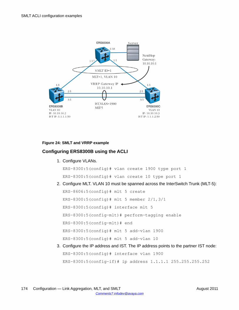
Figure 24: SMLT and VRRP example
Configuring ERS8300B using the ACLI
1. Configure VLANs.
ERS-8300:5(config)# vlan create 1900 type port 1ERS-8300:5(config)# vlan create 10 type port 1
2. Configure MLT. VLAN 10 must be spanned across the InterSwitch Trunk (MLT-5):
ERS-8606:5(config)# mlt 5 createERS-8300:5(config)# mlt 5 member 2/1,3/1ERS-8300:5(config)# interface mlt 5ERS-8300:5(config-mlt)# perform-tagging enableERS-8300:5(config-mlt)# endERS-8300:5(config)# mlt 5 add-vlan 1900ERS-8300:5(config)# mlt 5 add-vlan 10
3. Configure the IP address and IST. The IP address points to the partner IST node:
ERS-8300:5(config)# interface vlan 1900ERS-8300:5(config-if)# ip address 1.1.1.1 255.255.255.252
SMLT ACLI configuration examples
174 Configuration — Link Aggregation, MLT, and SMLT August 2011Comments? [email protected]
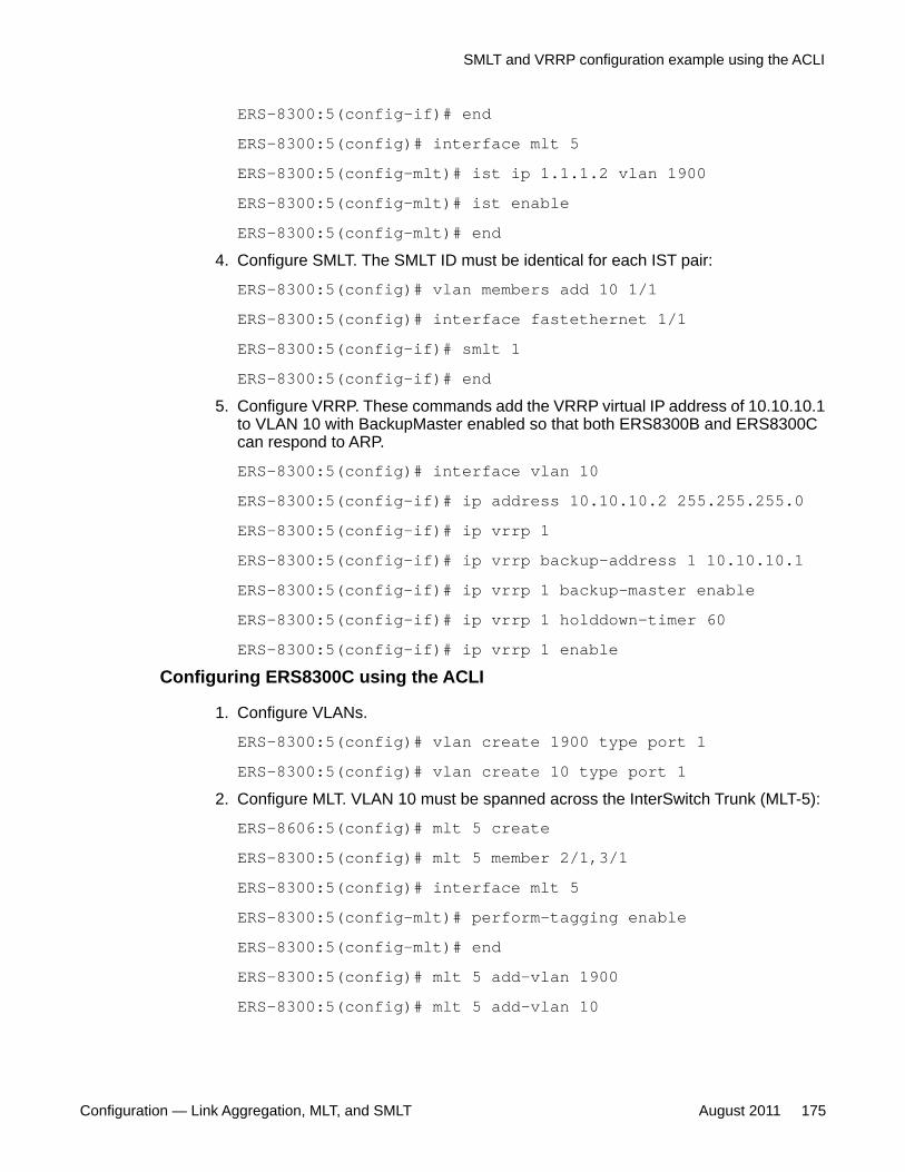
ERS-8300:5(config-if)# endERS-8300:5(config)# interface mlt 5ERS-8300:5(config-mlt)# ist ip 1.1.1.2 vlan 1900ERS-8300:5(config-mlt)# ist enableERS-8300:5(config-mlt)# end
4. Configure SMLT. The SMLT ID must be identical for each IST pair:
ERS-8300:5(config)# vlan members add 10 1/1ERS-8300:5(config)# interface fastethernet 1/1ERS-8300:5(config-if)# smlt 1ERS-8300:5(config-if)# end
5. Configure VRRP. These commands add the VRRP virtual IP address of 10.10.10.1to VLAN 10 with BackupMaster enabled so that both ERS8300B and ERS8300Ccan respond to ARP.
ERS-8300:5(config)# interface vlan 10ERS-8300:5(config-if)# ip address 10.10.10.2 255.255.255.0ERS-8300:5(config-if)# ip vrrp 1ERS-8300:5(config-if)# ip vrrp backup-address 1 10.10.10.1ERS-8300:5(config-if)# ip vrrp 1 backup-master enableERS-8300:5(config-if)# ip vrrp 1 holddown-timer 60ERS-8300:5(config-if)# ip vrrp 1 enable
Configuring ERS8300C using the ACLI
1. Configure VLANs.
ERS-8300:5(config)# vlan create 1900 type port 1ERS-8300:5(config)# vlan create 10 type port 1
2. Configure MLT. VLAN 10 must be spanned across the InterSwitch Trunk (MLT-5):
ERS-8606:5(config)# mlt 5 createERS-8300:5(config)# mlt 5 member 2/1,3/1ERS-8300:5(config)# interface mlt 5ERS-8300:5(config-mlt)# perform-tagging enableERS-8300:5(config-mlt)# endERS-8300:5(config)# mlt 5 add-vlan 1900ERS-8300:5(config)# mlt 5 add-vlan 10
SMLT and VRRP configuration example using the ACLI
Configuration — Link Aggregation, MLT, and SMLT August 2011 175

3. Configure the IP address and IST. The IP address points to the partner IST node:
ERS-8300:5(config)# interface vlan 1900ERS-8300:5(config-if)# ip address 1.1.1.2 255.255.255.252ERS-8300:5(config-if)# endERS-8300:5(config)# interface mlt 5ERS-8300:5(config-mlt)# ist ip 1.1.1.1 vlan 1900ERS-8300:5(config-mlt)# ist enableERS-8300:5(config-mlt)# end
4. Configure SMLT. The SMLT ID must be identical for each IST pair:
ERS-8300:5(config)# vlan members add 10 1/1ERS-8300:5(config)# interface fastethernet 1/1ERS-8300:5(config-if)# smlt 1ERS-8300:5(config-if)# end
5. Configure VRRP. These commands add the VRRP virtual IP address of 10.10.10.1to VLAN 10 with BackupMaster enabled so that both ERS8300B and ERS8300Ccan respond to ARP.
ERS-8300:5(config)# interface vlan 10ERS-8300:5(config-if)# ip address 10.10.10.3 255.255.255.0ERS-8300:5(config-if)# ip vrrp backup-address 1 10.10.10.1ERS-8300:5(config-if)# ip vrrp 1 backup-master enableERS-8300:5(config-if)# ip vrrp 1 holddown-timer 65ERS-8300:5(config-if)# ip vrrp 1 enable
Configuring ERS8300A using the ACLI
Configure MLT on A
ERS-8300:5# config vlan 10 create byport 1ERS-8300:5# config mlt 1 createERS-8300:5# config mlt 1 add ports 1/1,1/17ERS-8300:5# config mlt 1 add vlan 10
Use the show ip vrrp info command to view VRRP status.
SMLT ACLI configuration examples
176 Configuration — Link Aggregation, MLT, and SMLT August 2011Comments? [email protected]
Chapter 10: Customer Service
Visit the Avaya Web site to access the complete range of services and support that Avaya provides. Goto www.avaya.com or go to one of the pages listed in the following sections.
Getting technical documentationTo download and print selected technical publications and release notes directly from theInternet, go to www.avaya.com/support.
Getting product trainingOngoing product training is available. For more information or to register, you can access theWeb site at www.avaya.com/support. From this Web site, you can locate the Training contactslink on the left-hand navigation pane.
Getting help from a distributor or resellerIf you purchased a service contract for your Avaya product from a distributor or authorizedreseller, contact the technical support staff for that distributor or reseller for assistance.
Getting technical support from the Avaya Web siteThe easiest and most effective way to get technical support for Avaya products is from theAvaya Technical Support Web site at www.avaya.com/support.
Configuration — Link Aggregation, MLT, and SMLT August 2011 177

Customer Service
178 Configuration — Link Aggregation, MLT, and SMLT August 2011Comments? [email protected]

Index
A
ACLI SMLT configuration examples .........................155Adding an MLT-based SMLT ......................................58Adding ports to an MLT ..............................................56AlignmentErrors field ...........................................88, 123AStgEnable field .........................................................55ATSTG ......................................................................114
C
CarrierSenseErrors field .....................................88, 123collision errors, MLT ...................................................90Configuring a MultiLink trunk using the ACLI ............111Configuring a single port SMLT ..................................60Configuring a single-port SMLT using the CLI ............82Configuring an IST MLT .............................................63Configuring an IST MLT using the ACLI ...................121Configuring an IST MLT using the CLI .......................86Configuring an MLT ....................................................53Configuring an MLT-based SMLT using the CLI .........84Configuring an MultiLink trunk using the CLI ..............79Configuring LACP globally using Device Manager .....44Configuring LACP globally using the ACLI ...............100Configuring LACP globally using the CLI ...................72Configuring LACP on a port using Device Manager ...46Configuring LACP on a port using the ACLI .............102Configuring LACP on an MLT using the ACLI ...........115Configuring LACP on an MLT using the CLI ..............84Configuring port-based LACP using the CLI ..............74Configuring port-based VLACP using the ACLI ........129Configuring rate limiting using Device Manager .........62Configuring rate limiting using the ACLI ...................118Configuring rate limiting using the CLI .......................83Configuring VLACP globally using Device Manager . .65Configuring VLACP globally using the ACLI .............128Configuring VLACP on a port using Device Manager 66Creating a single-port SMLT using the ACLI .............117Creating an MLT .......................................................110
ACLI ...................................................................110Creating an MLT-based SMLT using the ACLI ..........119
D
DeferredTransmissions field ...............................88, 123Deleting a single port SMLT .......................................61
Deleting MLT-based SMLT using Device Manager .... 59Deleting ports from an MLT using Device Manager . . .57
E
ExcessiveCollisions field .....................................90, 126
F
FCSErrors field ...................................................88, 123FrameTooLongs field ..........................................88, 123Full mesh SMLT configuration example using the ACLI
......................................................................169Full mesh SMLT configuration example using the CLI 147
I
Id field, static link aggregation group ....................55, 80IEEE ...........................................................................14
802.1Q .................................................................14IEEE 802.3ad overview ..............................................19InternalMacReceiveErrors field ...........................88, 123InternalMacTransmitErrors field ..........................88, 123Interswitch trunk (IST) ................................................24
about ....................................................................24IST ..............................................................................24
about ....................................................................24
L
LACP and Spanning Tree ...........................................39MLT configuration ................................................39
LACP keys ..................................................................40LACP modes ..............................................................41LACP priority ..............................................................40LACP timers ...............................................................40LateCollisions field ..............................................90, 126Link aggregation .........................................................37
configuration considerations ................................37link aggregation configuration considerations ....15, 37,
38, 40LACP parameters ................................................40LAG rules .............................................................15MLT with LACP ....................................................37MLT with LACP and SMLT ...................................38
Loadsharing ................................................................23
Configuration — Link Aggregation, MLT, and SMLT August 2011 179

M
MLT configuration .......................................................14rules .....................................................................14
MLT network topology ................................................15configuration examples ........................................15
MLT with LACP .........................................................133CLI configuration example .................................133
MLT-based SMLT .......................................................30single port SMLT ..................................................30
MLT, See static link aggregation .................................11Multicast Distribution field, MLTs ................................55MultiLink .....................................................................12
trunking ................................................................12MultiLink trunk .......................................................15–17
BPDUs .................................................................17client/server configuration ....................................17switch-to-server configuration ..............................16switch-to-switch configuration ..............................15
MultiLink Trunking ......................................................18with LACP ............................................................18
MultipleCollisionFrames field ..............................90, 126
N
Name field ..................................................................55
P
PortMembers field ......................................................55PortType field .............................................................55
R
Removing an IST MLT ................................................64Routed Split MultiLink Trunking (RSMLT) ..................22
S
show mlt commands ..............................81, 90, 123, 125error collision ...........................................81, 90, 125error main ...........................................................123
single port SMLT .........................................................28about ....................................................................28
Single-port SMLT triangle configuration example usingthe ACLI .......................................................155
Single-port SMLT with SLPP configuration exampleusing the ACLI .............................................158
Single-port SMLT with SLPP configuration exampleusing the CLI ...............................................138
SingleCollisionFrames field .................................90, 126SMLT ..............................................22–24, 26, 28, 31–34
configuration example ..........................................24end station configuration example .......................26IP routing ..............................................................32IST .......................................................................24LACP support .......................................................31network design .....................................................34overview ...............................................................22single port ............................................................28
about .............................................................28topologies .............................................................24traffic flow examples ............................................26traffic flow rules ....................................................26versus STP ..........................................................23VRRP ...................................................................33VRRP Backup Master ..........................................33
SMLT advantages ......................................................23SMLT and IST .............................................................27
traffic flow example ..............................................27SMLT and SLPP .........................................................34SMLT and VRRP configuration example using the ACLI
......................................................................173SMLT and VRRP configuration example using the CLI . .
150SMLT CLI configuration examples ............................135SMLT configuration example using the ACLI ...........161SMLT configuration example using the CLI ..............141SMLT square ..............................................................38SMLT triangle configuration example using the CLI . 135Split MultiLink Trunking (SMLT) ..................................22SQETestErrors field ............................................88, 123Square SMLT configuration example using the ACLI 165Square SMLT configuration example using the CLI . 143static link aggregation ......................................11, 13, 14
IEEE 802.1Q tagging ...........................................14media type ...........................................................14port aggregation ...................................................11span modules .......................................................14supported media ..................................................14traffic distribution ..................................................13
SvlanPortType field, MLT ...........................................55
T
tagging, on MLT ports .................................................80traffic distribution , link aggregation ............................13
V
Viewing global LACP configuration information using theCLI .................................................................73
180 Configuration — Link Aggregation, MLT, and SMLT August 2011
Viewing LACP configuration information using the ACLI......................................................................105
Viewing LACP interface configuration information . . .107ACLI ...................................................................107
Viewing LACP parameters using Device Manager .... 51Viewing MLT collision error information using the ACLI
......................................................................125Viewing MLT Ethernet error information using the ACLI
......................................................................123Viewing MLT Ethernet error information using the CLI 88Viewing MLT information using the ACLI ..................116Viewing MLT-based SMLT information for the switch .59Viewing port-based LACP configuration information
using the CLI .................................................76
Viewing single-port SMLT information using DeviceManager ........................................................62
Viewing single-port SMLT information using the CLI ..82Viewing SMLT information using the CLI ....................83Viewing the global VLACP configuration using the ACLI
......................................................................128Viewing the IST configuration information using the CLI
.......................................................................87Viewing the IST configuration using the ACLI ..........122Viewing the port-based VLACP configuration using the
ACLI .............................................................130Viewing the SMLT configuration using the ACLI .......120Virtual Link Aggregation Control Protocol ..................34VlanIds field ................................................................55
Configuration — Link Aggregation, MLT, and SMLT August 2011 181