Embed Size (px)
Citation preview

Technical Report No.Third Edition
Concreteindustrialground floors
A guide to design and construction
Report of a Concrete SocietyWorking Party

Concrete Society Report TR34- Concrete industrial ground floorsThird Edition 2003
IMPORTANTErrata Notification
Would you please amend your copy of TR34 to correct the following:-
On page 50 - symbols and page 63 - Clause 9.11.3, change the word "percentage" to "ratio"in the definition of px and py.
Concrete industrialground floorsA guide to design and construction
Third Edition
Concrete industrial ground floors - A guide to design and constructionConcrete Society Technical Report No. 34Third Edition
ISBN 1 904482 01 5
© The Concrete Society 1988, 1994, 2003Published by The Concrete Society, 2003
Further copies and information about membership of The Concrete Society may be obtained from:
The Concrete SocietyCentury House, Telford AvenueCrowthorne, Berkshire RG45 6YS, UKTel: +44 (0)1344 466007, Fax: +44(0)1344 466008E-mail: [email protected], www.concrete.org.uk
Design and layout by Jon WebbIndex compiled by Linda SutherlandPrinted by Holbrooks Printers Ltd., Portsmouth, Hampshire
All rights reserved. Except as permitted under current legislation no part of this work may be photocopied, storedin a retrieval system, published, performed in public, adapted, broadcast, transmitted, recorded or reproduced inany form or by any means, without the prior permission of the copyright owner. Enquiries should be addressedto The Concrete Society.
The recommendations contained herein are intended only as a general guide and, before being used in connectionwith any report or specification, they should be reviewed with regard to the full circumstances of such use.Although every care has been taken in the preparation of this Report, no liability for negligence or otherwise canbe accepted by The Concrete Society, the members of its working parties, its servants or agents.
Concrete Society publications are subject to revision from time to time and readers should ensure that they inpossession of the latest version.
Concrete Society Technical Report No. 34Third Edition
Concrete industrialground floorsA guide to design and construction
Report of a Concrete Society Working Party
The Concrete Society
CONTENTS
Previous pageis blank
List of figures viiiList of tables ixMembers of the Project Committees xAcknowledgements xiPreface xiiGlossary of terms and abbreviations xiii
1 INTRODUCTION 1
1.1 Scope 11.2 Structure of the report 21.3 Procurement methods 31.4 Innovations in floor technology 31.5 Implications of new design recommendations 5
PART ONEOPERATING REQUIREMENTS 7
2 OVERVIEW OF FLOOR CONSTRUCTION 9
2.1 Introduction 92.2 Floor construction methods 9
2.2.1 Large area construction-jointed 9
2.2.2 Large area construction - jointless 102.2.3 Long strip construction 102.2.4 Wide bay construction 112.2.5 Two-layer construction 11
2.3 Cold stores 112.4 Pile-supported floors 11
3 FLOOR LOADINGS 12
3.1 Static loads 123.1.1 Introduction 123.1.2 Uniformly distributed loads 123.1.3 Line loads 133.1.4 Point loads 13
3.2 Materials handling equipment 163.2.1 Introduction 163.2.2 MHE operating at floor level 163.2.3 MHE operating in free-movement areas
and wide aisles 163.2.4 MHE operating in very narrow aisles 17
3.3 Classification of floor loadings 17
4 SURFACE REGULARITY 19
4.1 Introduction: the importance of surface regularity 194.2 Floor types: free and defined movement 204.3 Surface regularity in free-movement areas 22
4.4 Surface regularity in defined-movement areas 234.5 Survey practice for all floor types 254.6 Change of floor flatness with time 254.7 Converting floors to defined-movement 25
specifications
5 FLOOR SURFACE REQUIREMENTS 27
5.1 Introduction 275.2 Abrasion resistance 275.3 Chemical resistance 275.4 Colour and appearance 285.5 Cracking 285.6 Crazing 285.7 Curling 285.8 Delamination 295.9 Slip resistance 295.10 Surface aggregate 295.11 Surface fibres 295.12 Surface finish marks 30
PART TWODESIGN ASPECTS 31
6 SOILS, SUB-BASES AND MEMBRANES 336.1 Introduction 336.2 Design models for soils 33
6.2.1 Introduction 336.2.2 The Winkler model 33
6.3 Subgrades 336.3.1 Design considerations 336.3.2 Soil surveys 346.3.3 Subgrade construction 346.3.4 Imported fill and ground improvement 55
6.4 Sub-bases 356.4.1 General 356.4.2 Sub-base top surface tolerances 35
6.5 Membranes 36
7 REINFORCEMENT 37
7.1 Introduction 377.2 Steel reinforcement bar 377.3 Steel fabric 377.4 Steel fibres 387.5 Structural synthetic fibres 397.6 Reinforcement spacers and chairs 39
Concrete industrial ground floors
8 JOINTS 408.1 Introduction 40
8.2 Joint types 40
8.3 Free-movement joints 40
8.3.1 Purpose 40
8.3.2 Sawn free-movement joints 40
8.3.3 Formed free-movement joints 41
8.3.4 Wire guidance systems 41
8.3.5 Expansion joints 41
8.4 Restrained-movement joints 41
8.4.1 Purpose 41
8.4.2 Sawn restrained-movement joints 42
8.4.3 Formed restrained-movement joints 42
8.5 Tied joints 42
8.6 Isolation details 42
8.7 Performance of sawn and formed joints 42
8.8 Load-transfer mechanisms 44
8.8.1 Introduction 44
8.8.2 Aggregate interlock 44
8.8.3 Steel-fibre-reinforced concrete 45
8.8.4 Round and square dowels 45
8.8.5 Steel fabric reinforcement 45
8.8.6 Proprietary systems 45
8.9 Armouring of joints 45
8.9.1 Introduction 45
8.9.2 Anchorage fittings 46
8.9.3 Ease of construction 4(5
8.9.4 Shrinkage along joints 46
8.10 Joint layout 46
8.10.1 Joint spacing and detailing 46
8.10.2 Joint spacing and reinforcement 46
8.10.3 Jointless construction 47
8.11 Joints in cold stores 47
8.12 Joint sealants 48
8.12.1 Introduction 48
8.12.2 Joints in new floors 48
8.12.3 Sealant application 48
8.12.4 Other filling systems 49
8.12.5 Maintaining joints 49
9 STRENGTH AND SERVICEABILITY OFSLABS 50
Symbols 509.1 Introduction 519.2 Units 579.3 Design principles and criteria 57
9.3.1 Introduction 579.3.2 Ultimate limit state 579.3.3 Serviceability 52
9.4 Material properties 529.4.1 Concrete 529.4.2 Steel-fibre-reinforced concrete 52
9 A3 Synthetic-fibre-reinforced concrete 529.4.4 Steel fabric and bar 529.4.5 Modulus of subgrade reaction 53
9.4.6 Radius of relative stiffness 539.5 Actions (loads) 539.6 Partial safety factors 54
9.6.1 General 549.6.2 Partial safety factors for materials 549.6.3 Partial safety factors for actions 54
9.7 Yield line theory 559.7.1 Basic approach for point loads 559.7.2 Development of analyses for ground-
supported slabs 559.8 Design moment capacities 56
9.8.1 Steel-fibre-reinforced concrete 569.8.2 Synthetic-fibre-reinforced concrete 569.8.3 Reinforced concrete (bar and fabric) 56
9.9 Design equations 569.9.1 Introduction 569.9.2 Load locations 569.9.3 Point loads 579.9A Multiple point loads 589.9.5 Line loads and uniformly distributed
loads 589.10 Calculation of load transfer 60
9.10.1 Load transfer by dowels 609.10.2 Load transfer by fabric 629.10.3 Load transfer by proprietary systems 62
9.11 Punching shear 629.11.1 Introduction 629.11.2 Shear at the face of the loaded area 629.11.3 Shear on the critical perimeter 63
9.12 Checks for serviceability 639.12.1 Overview 639.12.2 Deflection control 639.12.3 Movements 64
PART THREECONCRETE PERFORMANCE ANDCOMPONENT MATERIALS 67
10 CONCRETE PERFORMANCE 69
10.1 Specification considerations 6910.2 Strength and related characteristics 69
10.2.1 Compressive and flexural strength 6910.2.2 Ductility of fibre-reinforced concrete 6910.2.3 Maturity of concrete in cold store floors 69
10.3 Shrinkage 6910.3.1 Introduction 6910.3.2 Drying shrinkage 7010.3.3 Early thermal contraction 7010.3.4 Crazing 71
vi
Contents
10.3.5 Plastic shrinkage 7110.4 Mix design for placing and finishing 7110.5 Abrasion resistance 7210.6 Chemical resistance 72
11 CONCRETE COMPONENTS 74
11.1 Cement 7411.1.1 Common cements and combinations 7411.1.2 Choice of cement / cement
combination 7411.1.3 Expansive cements 75
11.2 Aggregates 7511.2.1 Introduction 7511.2.2 Mechanical performance 7511.2.3 Drying shrinkage of aggregates 75
11.3 Admixtures 7511.3.1 Introduction 7511.3.2 High-range water-reducing admixtures 7611.3.3 Normal water-reducing admixtures and
retarding admixtures 7611.3.4 Accelerating admixtures 7611.3.5 Shrinkage-reducing admixtures 7611.3.6 Air-entraining admixtures 7611.3.7 Concrete production with admixtures 76
11.4 Dry shake finishes 7611.5 Steel fibres 7711.6 Synthetic fibres 77
11.6.1 Introduction 7711.6.2 Effect of microfibres on hardened
concrete 77
PART FOURBEST PRACTICE IN CONSTRUCTION ANDMAINTENANCE 79
12 FRAMEWORK FOR GOOD SITEPRACTICE 81
12.1 Introduction 8112.2 Health and safety 8112.3 Pre-construction planning 8112.4 Construction 8212.5 Protection of the new floor 8212.6 Post-construction 83
13 MAINTENANCE 8413.1 Introduction 8413.2 Cleaning 8413.3 Surface wear - abrasion 8413.4 Surface wear - scouring and impact damage 8413.5 Joints 8413.6 Cracks 85
References 86
APPENDIX AModel design brief 90
APPENDIX B
Worked example: Thickness design of a ground-supported floor slab 92Bl Introduction 92B2 Design data 92B3 Zone A: racking 93B4 Zone B: general storage/display 94B5 Zone C: internal wall (line load) 94B6 Zone D: mezzanine 94B7 Materials handling equipment 95B8 Relative position of truck wheel and racking leg 95B9 Deflection check 95
APPENDIX C
Floor regularity 97Cl Developments in floor surveying 97C2 Alternative method for surveying defined-
movement areas 97C3 Application of truck dimensions 100C4 Specifications outside the UK 1 00
APPENDIX D
Pile-supported slabs 101Dl Introduction 101D2 Alternative design approaches 101D3 Structural analysis 101D4 Section analysis 101
D4.1 Bar-or fabric-reinforced slab 101D4.2 Steel-fibre-reinforced slab 101D4.3 Punching shear 102D4.4 Serviceability 102
D5 Joints in piled slabs 102D5.1 Introduction 102D5.2 Tied joints 102D5.3 Formed free-movement joints 102
APPENDIX EDesign with steel fabric reinforcement 103E1 Supplement to Chapter 9, strength and
serviceability of slabs 103E2 Extension to Appendix B, thickness design of a
ground-supported floor slab 103E2.1 Zone A: Racking - Ultimate limit state 103E2.2 Materials handling equipment 104E2.3 Relative position of fork-lift truck and
racking leg 104
APPENDIX FSources of information 105
Sponsor profiles 107
Subject index 135
vii
Concrete industrial ground floors
LIST OF FIGURES
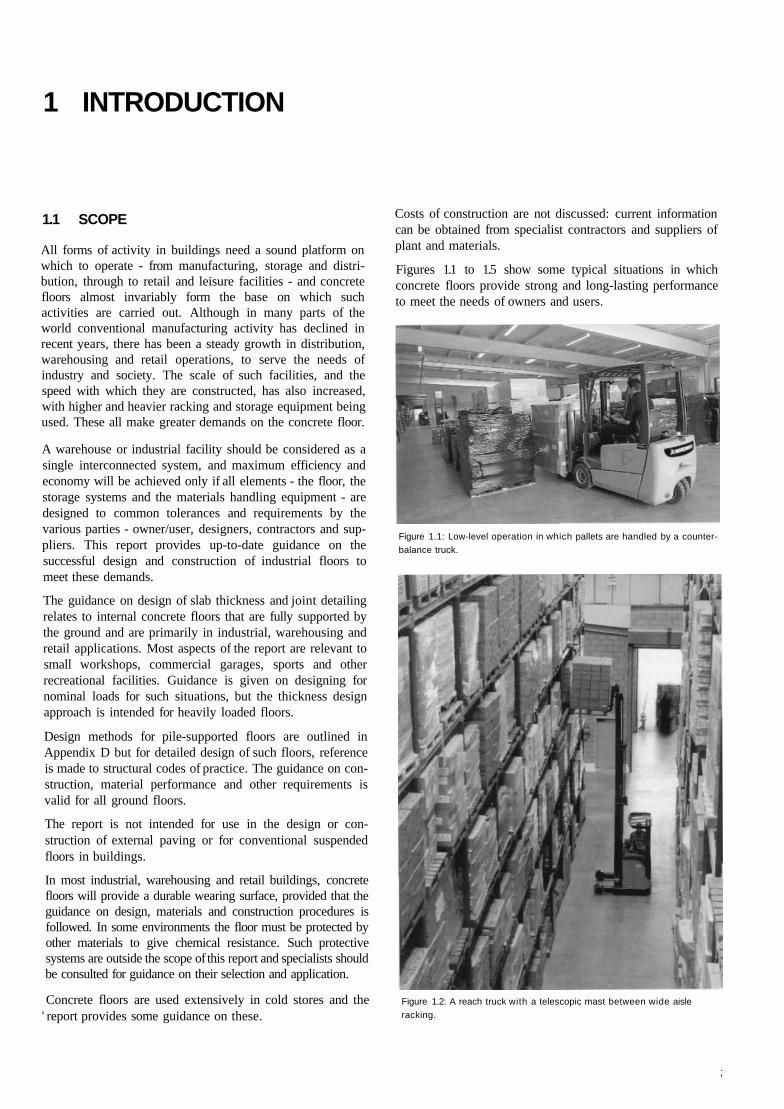
Figure 1.1 Low-level operation in which pallets are handled by acounterbalance truck, page 1
Figure 1.2 A reach truck with a telescopic mast between wide aisleracking, page 1
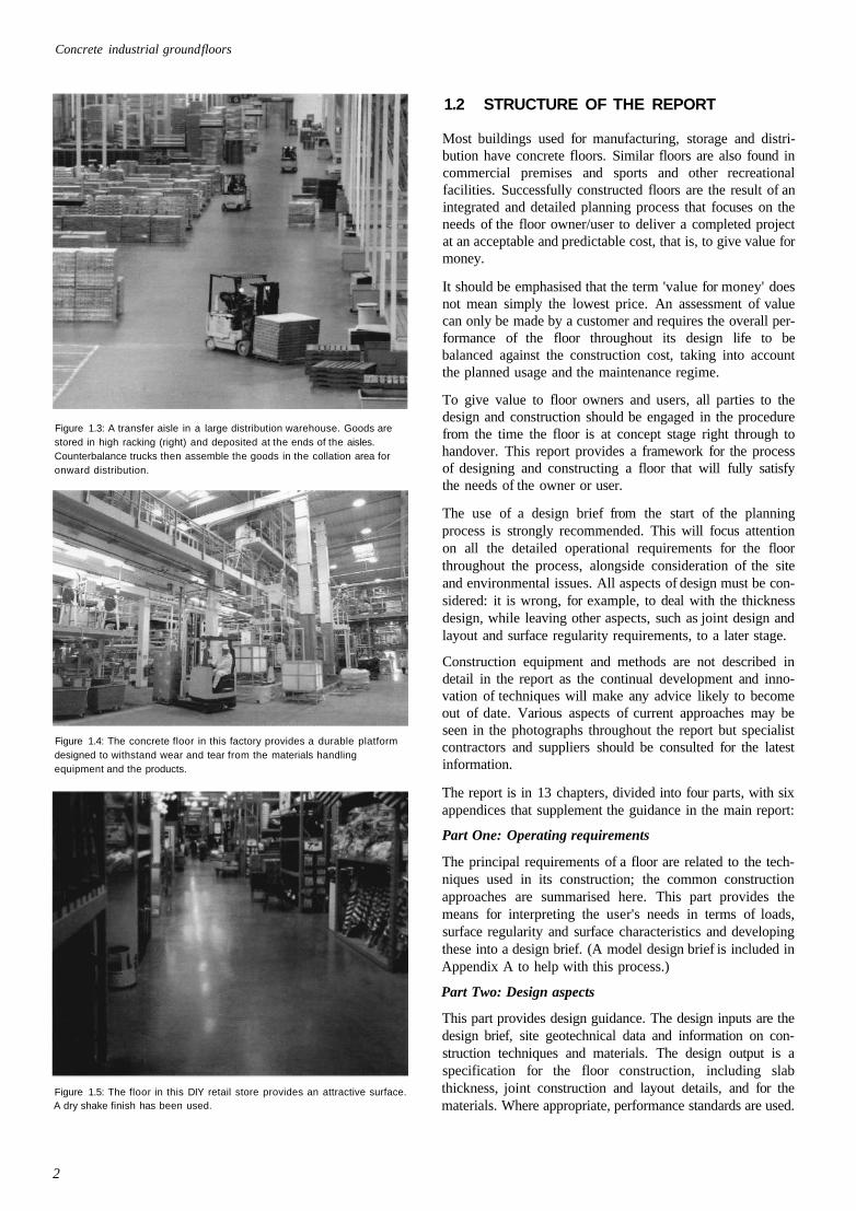
Figure 1.3 A transfer aisle in a large distribution warehouse. Goods arestored in high racking (right) and deposited at the ends of theaisles. Counterbalance trucks then assemble the goods in thecollation area for onward distribution, page 2
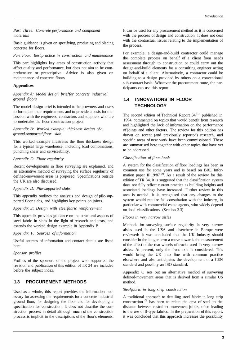
Figure 1.4 The concrete floor in this factory provides a durable platformdesigned to withstand wear and tear from the materialshandling equipment and the products, page 2
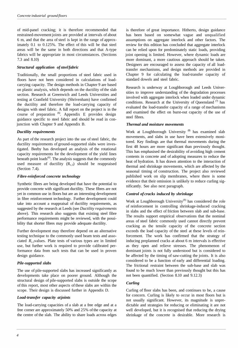
Figure 1.5 The floor in this DIY retail store provides an attractivesurface. A dry shake finish has been used, page 2
Figure 2.1 Typical slab construction, page 10
Figure 2.2 Large area construction. In the background (left) a laser
screed machine is spreading and levelling the concrete. Tothe right a dry shake finish is being spread mechanically. Inthe foreground, the concrete placed several hours earlier isbeing finished by a power float and a ride-on power trowel.page 10
Figure 2.3 Long strip construction, allowing access for levelling using ahighway straightedge, page 10
Figure 2.4 Typical construction layers in cold stores, page 11
Figure 3.1 Block stacking of unit loads, page 12
Figure 3.2 Rolls of paper are considered as unit loads. Note the heavy-duty dual-wheeled lift truck, page 12
Figure 3.3 Back-to-back storage racking with 'man-up' stacker trucksoperating in narrow aisles. Pallets are deposited at the ends ofthe racking for collection, page 13
Figure 3.4 Typical 'back-to-back' configuration of storage racking.page 14
Figure 3.5 Mobile pallet racking, page 14
Figure 3.6 Live storage systems, page 14
Figure 3.7 Drive-in racking, page 14
Figure 3.8 Push-back racking, page 15
Figure 3.9 Cantilever racking, page 15
Figure 3.10 Mezzanine (raised platform), page 15
Figure 3.11 Mezzanine used for access to storage, with racking below.page 15
Figure 3.12 Clad rack system, page 15
Figure 3.13 The small wheels on pallet trucks (such as that in the fore-ground) can be damaging to joints in floors, page 16
Figure 3.14 Counterbalance truck, page 17
Figure 3.15 'Man-up' stacker truck in a very narrow aisle warehouse.page 17
Figure 3.16 Stacker crane, running on a floor-mounted rail, page 18
Figure 4.1 Surface profiles, page 19
Figure 4.2 Flatness and levelness. page 19
Figure 4.3 Examples of measurements of Property I over 300 mm andthe resultant determination of change in elevational differenceover a distance of 300 mm (Property II). page 19
Figure 4.4 A free-movement area: marks from the rubber tyres of thematerials handling equipment may be seen, page 21
Figure 4.5 A defined-movement area in a very narrow aisle, page 21
Figure 4.6 Static lean, page 21
Figure 4.7 Floor surveying equipment, page 22
Figure 4.8 Profileograph in use in an aisle, page 24
Figure 4.9 Remediation in wheel tracks, page 24
Figure 4.10 Typical grinding operations, page 25
Figure 6.1 Conversion factors for different loading plate sizes, page 34
Figure 6.2 Relationship between modulus of subgrade reaction and insitu CBR. page 34
Figure 6.3 Proof loading of sub-base for construction traffic withconcrete truck, page 35
Figure 7.1 Dock levellers. Additional reinforcement may be needed inthe areas around each entrance, page 37
Figure 7.2 Typical load-deflection graph for steel-fibre-reinforcedconcrete beams, page 38
Figure 8.1 Sawn free-movement joint, page 40
Figure 8.2 Formed free-movement joints with various load-transfer andarris-protection systems, page 41
Figure 8.3 Sawn restrained-movement joint (shown with fabric), page 42
Figure 8.4 Formed restrained-movement joint, page 42
Figure 8.5 Tied joint, page 42
Figure 8.6 Isolation details around column, page 43
Figure 8.7 Slab isolation details at slab perimeter and columns, page 43
Figure 8.8 Joint sawing, page 43
Figure 8.9 Suggested mechanism of crack inducement, page 43
Figure 8.10 Concrete integrity and levels at sawn and formed joints.page 44
Figure 8.11 Permanent formwork, with dowel bars in place, for a formedrestrained-movement joint in a long strip construction. Thewalls and columns are protected with polythene, page 47
Figure 9.1 Approximate distribution of bending moments for an internalload, page 53
Figure 9.2 Development of radial and circumferential cracks in aconcrete ground-supported slab, page 55
Figure 9.3 Definitions of loading locations, page 56
Figure 9.4 Calculation of equivalent contact area for two adjacent pointloads, page 57
Figure 9.5 Adjacent point loads in very narrow aisles, page 57
Figure 9.6 Yield line patterns for multiple point loads, page 58
Figure 9.7 Use of Hetenyi's equations for a line load P. page 59
Figure 9.8 Loading patterns for uniformly distributed load, w, causingmaximum positive bending moment (upper drawing) andmaximum negative bending moment (lower drawing).page 59
Figure 9.9 Defined areas of uniformly distributed load, page 60
Figure 9.10 Behaviour of dowels, page 60
Figure 9.11 Critical perimeters for punching shear for internal, edge andcorner loading, page 62
Figure 9.12 Typical load-deflection relationship for steel-fibre-reinforcedground-supported slab, page 63
Figure 12.1 A well-laid sub-base is providing a sound platform for con-struction operations. Fabric is placed just ahead of the laserscreed machine so it is not displaced by this mobile plant.The building is almost completely enclosed, page 81
Figure 12.2 Successfully completed floor, page 82
Figure 12.3 The edge of the previous pour (foreground) is protected bymatting, which allows hand finishing of the edge of the newslab to be done easily and minimises the risk of splashes ofwet concrete spoiling the appearance of the cast slab, page 83
Figure Bl Plan of warehouse (not to scale), page 92
Figure B2 Punching shear perimeter at edge, page 93
Figure B3 Arrangement of loads for maximum hogging moment, page 94
Figure B4 Arrangement of mezzanine baseplate grid, page 94
Figure B5 Equivalent loaded areas for racking legs and fork-lift truckwheels, page 95
Figured Survey method, page 98
Figure C2 Surveying a planned defined-movement area with a pro-fileograph prior to installation of racking, page 98
Figure C3 Property B (= d2 - d1). page 98
Figure C4 Property D (= d2 -d1). page 98
Figure Dl Cross-sections of typical piled slabs (not to scale). page 101
Figure D2 Stress blocks for concrete with steel fibres and/or rein-forcement in flexure at the ultimate limit state. page 102
viii
Contents
LIST OF TABLES
Table 3.1 Descriptions of load types and examples, page 12
Table 4.1 Definition of surface regularity terms, page 20
Table 4.2 Permissible limits on Properties II and IV in free-movement
areas. page 22
Table 4.3 Permissible limits on Properties I, II and III in defined-
movement areas, page 24
Table 4.4 Permissible limits on Properties II and IV in FM 2 floors for
possible conversion to Category 1. page 26
Table 5.1 Performance classes for abrasion resistance, based on Table 4
of BS 8204-2: 2002. page 27
Table 6.1 Error in slab thickness design resulting from error in
estimation of modulus of subgrade reaction k. page 33
Table 6.2 Typical values of modulus of subgrade reaction k related to
soil type, page 34
Table 8.1 Sealant types and properties, page 48
Table 9.1 Strength properties for concrete, page 52
Table 9.2 Dimensions of standard square fabrics, page 53
Table 9.3 Influence of slab depth h and modulus of subgrade reaction kon the radius of relative stiffness / for/cu = 40 N/mm2.
page 54
Table 9.4 Design capacity of single dowels in shear, bearing andbending, page 61
Table 9.5 Maximum load per dowel (kN) to avoid bursting (punching)
of slabs, page 62
Table 9.6 Typical deflections for 20 mm round dowel, page 62
Table 9.7 Values of load-transfer capacity, Papp fab, based on Equations9.23 to 9.26, and using/y = 460 N/mm2, ys = 1.05, and
.v j-2.0 mm. page 62
Table 9.8 Values of deflection coefficient c for corner loading, page 64
Table 9.9 Influence of k on deflection of typical slab under a point load
of 60 kN. page 64
Table 9.10 Typical periods over which movements occur, page 64
Table 10.1 Approximate coefficient of linear thermal expansion of
concrete made with various aggregates, page 70
Table 10.2 Factors affecting abrasion resistance of concrete floors, page 73
Table 11.1 Effects of different cements and combinations on concrete
properties, page 74
Table Al Model design brief for concrete industrial ground floors
page 90, 91
Table Cl Floor classification for defined movement, page 99
Table C2 Applied limit values for MHE dimensions T= 1.3 m and L =
1.8 m. page 99
Table C3 Worked example: applied limit values for MHE dimensions
T= 1.3 m and L = 1.8 m. page 99
Table C4 Comparison between surface regularity measurements TR 34
limits and F-numbers. page 100
ix
MEMBERS OF THE PROJECT COMMITTEES
PROJECT STEERING GROUP
Peter Goring John Doyle Construction Ltd (Chairman)Simon Austin Loughborough UniversityStuart Dorey Precision Concrete FloorsRob Gaimster RMC Group plcDavid Harvey Stuarts Industrial Flooring LtdTony Hulett The Concrete Society (Secretary and Project Manager)Pat Kinehan ABS Brymar Floors LtdKevin Louch Stanford Industrial Concrete Flooring LtdJohn Mason Alan Baxter & Associates (representing the Department of Trade and Industry)Phil Shaw Burks Green
DESIGN SUB-GROUP
Simon Austin Loughborough University (Convenor)Derrick Beckett University College LondonJon Bishop formerly Loughborough UniversityDavid Clark Bekaert Building ProductsJohn Clarke The Concrete SocietyXavier Destree TrefilARBED Bissen SARobert Lindsay ArupMartin Rogers George Hutchinson Associates LtdPhil Shaw Burks GreenPaul Sprigg Sprigg Little PartnershipHendrick Thooft N.V. Bekaert S.A.Henry Tomsett Arup
CONSTRUCTION SUB-GROUP
Stuart Dorey Precision Concrete Floors (Convenor)George Barnbrook Concrete Advisory ServicePaul Choularton Mitchell McFarlane & Partners LtdAndrew Keen Somero Enterprises LtdKevin Louch Stanford Industrial Concrete Flooring LtdChris Packer HBG Construction LtdMartin Rogers CFS (Combined Flooring Services) LtdKevin Sutherland Tarmac Topmix Ltd
MATERIALS SUB-GROUP
Rob Gaimster RMC Group plc (Convenor)John Dransfield Cement Admixtures AssociationNeil Henderson Mott MacDonaldDarren Murgatroyd ABS Brymar Floors LtdBill Price British Cement AssociationDave Smith BRC Special ProductsShaun Speers SIKA Armorex
USER NEEDS SUB-GROUP
Phil Shaw Burks Green (Convenor)John Bolus British Industrial Truck AssociationIain Christie Roy Hatfield LtdKevin Dare Face Consultants LtdKen Hall Prologis Developments LtdDavid Harvey Stuarts Industrial Flooring LtdJohn Hodgins Tibbett & BrittenRay Lawless Jungheinrich (GB) LtdAlan Worrell SSI Schaefer Ltd
X
ACKNOWLEDGEMENTS
The authors of this report are employed by The Concrete Society. Thework reported herein was carried under a Contract jointly funded byThe Concrete Society, members of the Association of ConcreteIndustrial Flooring Contractors and the Secretary of State for Tradeand Industry placed in July 2000. Any views expressed are not nec-essarily those of the Secretary of State for Trade and Industry.
The project to revise Technical Report 34 was undertaken as aConcrete Society project under the guidance of a Steering Groupwith members drawn from the various specialist organisationsinvolved in procuring, designing and constructing concrete floors.The Chairman was Peter Goring, Technical Director of John DoyleConstruction Ltd. The project was managed by Tony Hulett,Principal Engineer, The Concrete Society, who was also responsiblefor the overall drafting and collation of material for the report.Derrick Beckett, Visiting Professor at the Department of Civil andEnvironmental Engineering, University College London, and DrJohn Clarke, Principal Engineer, The Concrete Society, undertookthe preparation of the sections on design, and the worked examples.The technical editor was Nick Clarke, Publications Manager of TheConcrete Society.
The review of surface regularity requirements for floors was animportant aspect of the project. The Society is grateful to ACIFC
members Kevin Dare of Face Consultants Ltd who provided consid-erable resources for surveying and analysis and to Kevin Louch ofStanford Industrial Concrete Floors Ltd and Darryl Eddy of TwintecIndustrial Flooring Ltd for making available floors for this research.
Extensive consultation and review of the project and drafts of thisreport were arranged throughout the two and a half years of theproject. This included a series of briefings and discussions withengineers and contractors, and with the engineers of the ConcreteAdvisory Service. The Concrete Society is grateful to all those whoprovided feedback and comments on the drafts, listed below.
The Concrete Society is grateful to the following for providing pho-tographs for use in the report:
Bekaert, Concrete Grinding Ltd, Face Consultants Ltd, Gazeley,Jungheinrich, Lansing Linde Ltd, Permaban, Precision ConcreteFloors, SSI Schaefer, Stanford Industrial Concrete Flooring Ltd,Stuarts Industrial Flooring Ltd, Synthetic Industries, TwintecIndustrial Flooring.
The photographs have been selected to illustrate particular aspectsof floor construction and use, and some working practices shownmay not necessarily meet with current site practice.
Etienne AlexanderMike AmodeoRodney ArnoldMalcolm BaileyProf Andrew BeebyJimmy Bittles
Bernard BouhonJohn BrownJames BuckinghamAndrew CallensGregor CameronRalph ChaplinMike ConnellKevin CorbyDavid CudworthRichard DayAlan DobbinsDarryl EddySimon EvansPaul FlemingMatthew FrostPaul FrostMichael GaleGeorge GarberCharles GoodchildKen GreenheadProf. Tom HarrisonTony HartleyChris HendersonJan HennigChris HughesJames IgoeAlistair Keith
Rinol GroupMike Amodeo (Contractors) LtdPermaban LtdRadlett ConsultantsUniversity of LeedsInternational Association of ColdStorage ContractorsSilidur (UK) LtdSynthetic Industries Europe LtdSilidur (UK) LtdBekaert Building ProductsA J Clark Concrete FlooringConsultantAppleby Group LtdFibercon UK LtdWhite Young GreenThe Concrete SocietyTwintec Industrial Flooring LtdTwintec Industrial Flooring LtdSynthetic Industries Europe LtdLoughborough UniversityNottingham Trent UniversityFloor Surveys LtdSika ArmorexConsultant, USAReinforced Concrete CouncilBeers ConsultantsQuarry Products AssociationRMC Group picStuarts Industrial Flooring LtdFosseway Flooring SystemsRapra Technology LtdDon Construction Products LtdBirse
Paul KellyJohn LayDave LevertonAlan McDonackDarren MurgattroydDirk NemegeerSteve ParryBruce PerryYves Pestel de BordDarren PinderDavid PostinsSteve ProbutDerek ReadPeter RemoryLee PettitDavid RobertsArthur RousDr Massud SadegzadehNeil SandersSteve SimmonsDeryk SimpsonChris SketchleyPat SnowdenDr Roger SymJohn SteelPeter ThompsonRichard Tilden SmithVassoulla VassouAndrew WaringJean Marc WeiderJon WilliamsonNeil WilliamsonPaul Withers
Somero Enterprises LtdRMC Group picKier WesternROM LtdABS Brymar Floors LtdN.V. Bekaert S.A.Silidur (UK) LtdGrace Construction Products LtdACIFC FranceConcrete Grinding LtdProLogisLansing Linde LtdCompriband LtdN.V. Bekaert S.A.GazeleyFosrocFloor Surveys LtdUniversity of AstonDon Construction Products LtdSinbad PlantConcrete Advisory ServiceScott WilsonSnowden Flooring LtdConsultant StatisticianAMECSlough EstatesACIFCUniversity of AstonAndrew Waring AssociatesRocland FranceTwintec Industrial Flooring LtdMonofloor TechnologyJoynes Pyke & Associates(now HPBW (Consultants) Ltd)
Xi
PREFACE
This is the third edition of Concrete Society Technical Report34. The previous editions were published in 1988 and 1994.These became identified as the leading publications on manyof the key aspects of concrete industrial ground floors, initiallyin the UK, and then in other parts of the world, especiallyEurope. The Concrete Society's experience in this field hassteadily grown, through the expertise of its members who spe-cialise in industrial floors, and through the experience of theengineers of the Concrete Advisory Service, who regularlydeal with questions and problems relating to floors.
Guidance on the design and construction of ground-supportedconcrete floors was developed and published by the Cementand Concrete Association in the 1970s and 1980s. ConcreteSociety Technical Report 34 was published in 1988 and tookaccount of the rapid development of new construction tech-niques, and gave guidance on thickness design. The second(1994) edition of TR 34(l) updated the guidance, but both theseeditions depended on and referred to the earlier publicationsfor the design methodology.
A supplement to TR 34 was published in 1997 (2) dealing withflatness in free-movement areas, which is superseded by thispresent publication. The Society has also published guidanceon particular aspects of concrete floors, in the form of separatepublications (3), and articles, Current Practice Sheets and sup-plements to Concrete magazine.
This edition of Technical Report 34 differs from previouseditions in two key aspects. Firstly, guidance on thicknessdesign of slabs is complete, with minimal need for referenceto other documents. Secondly, wherever possible, theguidance is non-prescriptive, allowing designers and con-tractors to use their skills to develop economic solutions forproviding the required performance.
This edition is the result of a thorough review of all aspects offloor design and construction, including developments inEurope and the USA. The thickness design guidance is nowprimarily based on a limit state format. Surface regularityrequirements have been reviewed in detail as a result of newsurvey work. The terminology for joints has been revised tomake their function clear. Guidance on the specification ofconcrete now reflects current thinking on the role of cement,in that water/cement ratio is of greater significance thancement content.
It is anticipated that TR 34 will assist the development of inter-national standards.
The Society acknowledges with thanks the support andassistance of its members and of the concrete flooring industrywho have contributed to the preparation of this report, and alsothe help and comments provided by many other individualsand companies, both in the UK and overseas.
xii
GLOSSARY OF TERMS AND ABBREVIATIONS
Key terms and abbreviations are defined below. A list of thesymbols used in the report may be found at the start ofChapter 9.
Abrasion - Wearing away of the concrete surface byrubbing, rolling, sliding, cutting or impact forces. (Sections5.2 and 10.5)
Aggregate interlock - Mechanism that transfers load acrossa crack in concrete by means of interlocking, irregularaggregate and cement paste surfaces on each side of thecrack. (Section 8.8.2)
APR - adjustable pallet racking. (Section 3.1.4)
Armoured joint- Steel protection to joint arrises. (Section 8.9)
Block stacking - Unit loads, typically pallet loads, paperreels or similar goods, stacked directly on a floor, usuallyone on top of another. (Section 3.1.2)
Bump cutting - The process of using a straight edge toremove high spots when levelling the surface of a floorduring construction. (Section 2.2.1)
California bearing ratio (CBR) - A measure of the load-bearing capacity of the sub-base or subgrade. (Section 6.3)
Crazing - Pattern of fine, shallow random cracks on thesurface of concrete. (Section 5.6)
Curling - Local uplifting at the edges of the slab due to dif-ferential drying shrinkage between the top and bottomsurfaces. (Sections 4.6 and 5.7)
Datum - A reference point taken for surveying. (Chapter 4)
Defined-movement area - Very narrow aisles in ware-houses where materials handling equipment can move onlyin defined paths. (Sections 4.2 and 4.4)
Delamination - Debonding of thin layer of surface concrete.(Sections 5.8 and 11.3.6)
Dominant joint - A joint that opens wider than adjacent(dormant) joints in a floor with sawn joints. (Section 8.10.2)
Dormant joint - Sawn joint that does not move, usuallybecause of failure of crack to form below the saw cut; gen-erally associated with a dominant joint. (Section 8.10.2)
Dowel - Round steel bar or proprietary device used totransfer shear loads from one slab to the next across a jointand to prevent differential vertical movement, while per-mitting differential horizontal movement. (Section 8.8)
Dry shake finish - A mixture of cement and fine hardaggregate, and sometimes admixtures and pigment, applieddry as a thin layer and trowelled into the fresh concrete, to
improve abrasion resistance, suppress fibres and sometimesto colour the surface. (Section 11.4)
Ductility - The ability of a slab to carry load after cracking.(Sections 7.3 and 7.4)
Elevational difference - The difference in height betweentwo points. (Section 4.1)
Flatness - Surface regularity over short distances, typically300 mm. (Section 4.1)
Formed joints - Joint formed by formwork. (Chapter 8)
Free-movement areas - Floor areas where materials handlingequipment can move freely in any direction. (Chapter 4)
Free-movement joint - Joint designed to provide aminimum of restraint to horizontal movements caused bydrying shrinkage and temperature changes in a slab, whilerestricting relative vertical movement. (Section 8.3)
Isolation detail - Detail designed to avoid any restraint to aslab by fixed elements such as columns, walls, bases or pits,at the edge of or within the slab. (Section 8.6)
Joints - Vertical discontinuity provided in a floor slab toallow for construction and/or relief of strains. The termi-nology relating to the various types of joint is complex, andreference may be made to the definitions of individual jointtypes. (Chapter 8)
Jointless floors - Floors constructed in large panels typ-ically 50 m square without intermediate joints. (Section 2.2)
Large area construction - Area of floor of several thousandsquare metres laid in continuous operation. (Section 2.2)
Levelness - Surface regularity over a longer distance, typ-ically 3 m, and to datum. (Section 4.1)
Line loads - Loads acting uniformly over extended length.(Sections 3.1.3 and 9.9.5)
Load-transfer capacity - The load-carrying capacity ofjoints in shear. (Section 8.8)
Long strip construction - Area of floor laid in strips.(Section 2.2)
Mezzanine - Raised area, e.g. for offices, above anindustrial floor but supported by it; typically a steel frame onbaseplates. (Section 3.1.4)
MHE - Materials handling equipment. (Section 3.2)
Modulus of subgrade reaction - Measure of the stiffness ofthe subgrade; load per unit area causing unit deflection.(Section 6.2)
xiii
Concrete industrial ground floors
Movement accommodation factor (MAF) - Themovement a joint sealant can accept in service expressed asa percentage of its original width. (Section 8.12)
Panel - Smallest unit of a floor slab bounded by joints.{Chapter 8)
Pile-supported slab - Floor constructed on, and supportedby, piles; used where ground-bearing conditions are inad-equate for a ground-supported floor. (Section 2.4, AppendixD)
Point load - Concentrated load from baseplate or wheel.(Section 3.1.4)
Power finishing - Use of machinery for floating and trow-elling floors. (Chapter 10)
'Property' - term used for defining floor regularity: eleva-tional differences or measurements derived from elevationaldifferences that are limited for each class of floor (Section4.1):
Property I - The elevational difference in mm betweentwo points 300 mm apart.
Property II - To control flatness, the change in eleva-tional difference between two consecutive measurementsof elevational difference (Property I) each measured over300 mm.
Property HI - The elevational difference between thecentres of the front load wheels of materials handlingequipment in mm.
Property IV - To control levelness, the elevational dif-ference between fixed points 3 m apart.
Racking - Systems of frames and beams for storage, usuallyof pallets. (Section 3.1.4)
Racking end frames - Pairs of vertical steel sectionmembers connected by frame bracing, which support rackingshelves carrying stored goods. (Section 3.1.4)
Remedial grinding - The process of removing areas of afloor surface by abrasive grinding of the hardened concreteusually in order to achieve the required surface regularity.(Chapter 4)
Restrained-movement joint - Joint designed to allowlimited movement to relieve shrinkage-induced stresses in aslab at pre-determined positions. (Section 8.4)
Sawn joint - Joint in slab where a crack is induced beneatha saw cut. (Chapter 8)
SFRC - Steel-fibre-reinforced concrete. (Section 9.6.2)
Slab - Structural concrete element finished to provide thewearing surface of a floor; can also be overlaid by screeds orother layers.
Slip membrane - Plastic sheet laid on the sub-base beforeconcrete is placed, to reduce the friction between slab andsub-base. (Section 6.5) Note: other forms of membrane areused for other requirements, e.g. gas membranes.
Slip resistance - The ability of a floor surface to resistslippage. (Section 5.9)
Sub-base - Layer (or layers) of materials on top of thesubgrade to form a working platform on which the slab isconstructed. (Section 6.4)
Subgrade - The upper strata of the existing soil under aground floor. (Section 6.3)
Surface regularity - Generic term to describe the departureof a floor profile from a theoretical perfect plane. (Chapter 4)
Tang - Shear stud or fitting on armoured joint to providebond to adjacent concrete. (Section 8.9)
Tied joint - Joint in a slab provided to facilitate a break inconstruction at a point other than a free-movement joint; suf-ficient reinforcement runs through the joint to preventmovement. (Section 8.5)
Toughness - Alternative term to ductility (which is the pre-ferred term), used with reference to steel-fibre-reinforcedconcrete. (Section 8.4)
Uniformly distributed load - Load acting uniformly overrelatively large area. (Section 3.1.2)
VNA - Very narrow aisle. (Section 3.1.4)
Wearing surface - The top surface of a concrete slab orapplied coating on which the traffic runs. (Section 2.2)
xiv
1 INTRODUCTION
1.1 SCOPE
All forms of activity in buildings need a sound platform onwhich to operate - from manufacturing, storage and distri-bution, through to retail and leisure facilities - and concretefloors almost invariably form the base on which suchactivities are carried out. Although in many parts of theworld conventional manufacturing activity has declined inrecent years, there has been a steady growth in distribution,warehousing and retail operations, to serve the needs ofindustry and society. The scale of such facilities, and thespeed with which they are constructed, has also increased,with higher and heavier racking and storage equipment beingused. These all make greater demands on the concrete floor.
A warehouse or industrial facility should be considered as asingle interconnected system, and maximum efficiency andeconomy will be achieved only if all elements - the floor, thestorage systems and the materials handling equipment - aredesigned to common tolerances and requirements by thevarious parties - owner/user, designers, contractors and sup-pliers. This report provides up-to-date guidance on thesuccessful design and construction of industrial floors tomeet these demands.
The guidance on design of slab thickness and joint detailingrelates to internal concrete floors that are fully supported bythe ground and are primarily in industrial, warehousing andretail applications. Most aspects of the report are relevant tosmall workshops, commercial garages, sports and otherrecreational facilities. Guidance is given on designing fornominal loads for such situations, but the thickness designapproach is intended for heavily loaded floors.
Design methods for pile-supported floors are outlined inAppendix D but for detailed design of such floors, referenceis made to structural codes of practice. The guidance on con-struction, material performance and other requirements isvalid for all ground floors.
The report is not intended for use in the design or con-struction of external paving or for conventional suspendedfloors in buildings.
In most industrial, warehousing and retail buildings, concretefloors will provide a durable wearing surface, provided that theguidance on design, materials and construction procedures isfollowed. In some environments the floor must be protected byother materials to give chemical resistance. Such protectivesystems are outside the scope of this report and specialists shouldbe consulted for guidance on their selection and application.
Concrete floors are used extensively in cold stores and the' report provides some guidance on these.
Costs of construction are not discussed: current informationcan be obtained from specialist contractors and suppliers ofplant and materials.
Figures 1.1 to 1.5 show some typical situations in whichconcrete floors provide strong and long-lasting performanceto meet the needs of owners and users.
Figure 1.1: Low-level operation in which pallets are handled by a counter-balance truck.
Figure 1.2: A reach truck with a telescopic mast between wide aisleracking.
;
Concrete industrial ground floors
Figure 1.3: A transfer aisle in a large distribution warehouse. Goods arestored in high racking (right) and deposited at the ends of the aisles.Counterbalance trucks then assemble the goods in the collation area foronward distribution.
Figure 1.4: The concrete floor in this factory provides a durable platformdesigned to withstand wear and tear from the materials handlingequipment and the products.
Figure 1.5: The floor in this DIY retail store provides an attractive surface.A dry shake finish has been used.
1.2 STRUCTURE OF THE REPORT
Most buildings used for manufacturing, storage and distri-bution have concrete floors. Similar floors are also found incommercial premises and sports and other recreationalfacilities. Successfully constructed floors are the result of anintegrated and detailed planning process that focuses on theneeds of the floor owner/user to deliver a completed projectat an acceptable and predictable cost, that is, to give value formoney.
It should be emphasised that the term 'value for money' doesnot mean simply the lowest price. An assessment of valuecan only be made by a customer and requires the overall per-formance of the floor throughout its design life to bebalanced against the construction cost, taking into accountthe planned usage and the maintenance regime.
To give value to floor owners and users, all parties to thedesign and construction should be engaged in the procedurefrom the time the floor is at concept stage right through tohandover. This report provides a framework for the processof designing and constructing a floor that will fully satisfythe needs of the owner or user.
The use of a design brief from the start of the planningprocess is strongly recommended. This will focus attentionon all the detailed operational requirements for the floorthroughout the process, alongside consideration of the siteand environmental issues. All aspects of design must be con-sidered: it is wrong, for example, to deal with the thicknessdesign, while leaving other aspects, such as joint design andlayout and surface regularity requirements, to a later stage.
Construction equipment and methods are not described indetail in the report as the continual development and inno-vation of techniques will make any advice likely to becomeout of date. Various aspects of current approaches may beseen in the photographs throughout the report but specialistcontractors and suppliers should be consulted for the latestinformation.
The report is in 13 chapters, divided into four parts, with sixappendices that supplement the guidance in the main report:
Part One: Operating requirements
The principal requirements of a floor are related to the tech-niques used in its construction; the common constructionapproaches are summarised here. This part provides themeans for interpreting the user's needs in terms of loads,surface regularity and surface characteristics and developingthese into a design brief. (A model design brief is included inAppendix A to help with this process.)
Part Two: Design aspects
This part provides design guidance. The design inputs are thedesign brief, site geotechnical data and information on con-struction techniques and materials. The design output is aspecification for the floor construction, including slabthickness, joint construction and layout details, and for thematerials. Where appropriate, performance standards are used.
2
Introduction
3
Part Three: Concrete performance and componentmaterials
Basic guidance is given on specifying, producing and placingconcrete for floors.
Part Four: Best practice in construction and maintenance
This part highlights key areas of construction activity thataffect quality and performance, but does not aim to be com-prehensive or prescriptive. Advice is also given onmaintenance of concrete floors.
Appendices
Appendix A: Model design brief for concrete industrialground floors
The model design brief is intended to help owners and usersto formulate their requirements and to provide a basis for dis-cussion with the engineers, contractors and suppliers who areto undertake the floor construction project.
Appendix B: Worked example: thickness design of aground-supported floor slab
This worked example illustrates the floor thickness designfor a typical large warehouse, including load combinations,punching shear and serviceability,
Appendix C: Floor regularity
Recent developments in floor surveying are explained, andan alternative method of surveying the surface regularity ofdefined-movement areas is proposed. Specifications outsidethe UK are also discussed.
Appendix D: Pile-supported slabs
This appendix outlines the analysis and design of pile-sup-ported floor slabs, and highlights key points on joints.
Appendix E: Design with steel fabric reinforcement
This appendix provides guidance on the structural aspects ofsteel fabric in slabs in the light of research and tests, andextends the worked design example in Appendix B.
Appendix F: Sources of information
Useful sources of information and contact details are listedhere.
Sponsor profiles
Profiles of the sponsors of the project who supported therevision and publication of this edition of TR 34 are includedbefore the subject index.
1.3 PROCUREMENT METHODS
Used as a whole, this report provides the information nec-essary for assessing the requirements for a concrete industrialground floor, for designing the floor and for developing aspecification for construction. It does not describe the con-struction process in detail although much of the constructionprocess is implicit in the descriptions of the floor's elements.
It can be used for any procurement method as it is concernedwith the process of design and construction. It does not dealwith the contractual issues relating to the implementation ofthe process.
For example, a design-and-build contractor could managethe complete process on behalf of a client from needsassessment through to construction or could carry out thedesign-and-build elements for a consulting engineer actingon behalf of a client. Alternatively, a contractor could bebuilding to a design provided by others on a conventionalsub-contract basis. Whatever the procurement route, the par-ticipants can use this report.
1.4 INNOVATIONS IN FLOORTECHNOLOGY
The second edition of Technical Report 34 (1), published in1994, commented on topics that would benefit from researchand highlighted the lack of information on the performanceof joints and other factors. The review for this edition hasdrawn on recent (and previously reported) research, andspecific areas of new work have been commissioned. Theseare summarised here together with other topics that have yetto be addressed.
Classification of floor loads
A system for the classification of floor loadings has been incommon use for some years and is based on BRE Infor-mation paper IP 19/87 (4). As a result of the review for thisedition of TR 34, it is suggested that the classification systemdoes not fully reflect current practice as building heights andassociated loadings have increased. Further review in thisarea is needed. It is recognised that any changes to thesystem would require full consultation with the industry, inparticular with commercial estate agents, who widely dependon load classifications. (Section 3.3)
Floors in very narrow aisles
Methods for surveying surface regularity in very narrowaisles used in the USA and elsewhere in Europe werereviewed: it was concluded that the UK industry shouldconsider in the longer term a move towards the measurementof the effect of the rear wheels of trucks used in very narrowaisles. At present, only the front axle is considered. Thiswould bring the UK into line with common practiceelsewhere and also anticipates the development of a CENstandard and possibly an ISO standard.
Appendix C sets out an alternative method of surveyingdefined-movement areas that is derived from a similar USmethod.
Steel fabric in long strip construction
A traditional approach to detailing steel fabric in long stripconstruction (5) has been to relate the area of steel to thedistance between restrained-movement joints, often leadingto the use of B-type fabrics. In the preparation of this report,it was concluded that this approach increases the possibility
Concrete industrial ground floors
of mid-panel cracking; it is therefore recommended thatrestrained-movement joints are provided at intervals of about6 m, and that the area of steel is kept in the range of approx-imately 0.1 to 0.125%. The effect of this will be that steelareas will be the same in both directions and that A-typefabrics will be appropriate in most circumstances. (Sections7.3 and 8.10)
Structural application of steel fabric
Traditionally, the small proportions of steel fabric used infloors have not been considered in calculations of load-carrying capacity. The design methods in Chapter 9 are basedon plastic analysis, which depends on the ductility of the slabsection. Research at Greenwich and Leeds Universities andtesting at Cranfield University (Shrivenham) have confirmedthe ductility and therefore the load-carrying capacity ofdesigns with steel fabric. A full report on the project is in thecourse of preparation (6). Appendix E provides designguidance specific to steel fabric and should be read in con-junction with Chapter 9 and Appendix B.
Ductility requirements
As part of the research project into the use of steel fabric, theductility requirements of ground-supported slabs were inves-tigated. Beeby has developed an analysis of the rotationalcapacity requirements for the development of the yield linesbeneath point loads(6). The analysis suggests that the commonlyused measure of ductility (Rc,3) should be reappraised(Section 7.4).
Fibre-reinforced concrete technology
Synthetic fibres are being developed that have the potential toprovide concrete with significant ductility. These fibres are notyet in common use in floors but are an interesting developmentin fibre reinforcement technology. Further development couldtake into account a reappraisal of ductility requirements, assuggested by the research at Leeds (see Ductility requirementsabove). This research also suggests that existing steel fibreperformance requirements might be reviewed, with the possi-bility that shorter fibres may provide adequate ductility.
Further development may therefore depend on an alternativetesting technique to the commonly used beam tests and asso-ciated Rc,3values. Plate tests of various types are in limiteduse, but further work is required to provide calibrated per-formance data from such tests that can be used in provendesign guidance.
Pile-supported slabs
The use of pile-supported slabs has increased significantly asdevelopments take place on poorer ground. Although thestructural design of pile-supported slabs is outside the scopeof this report, most other aspects of these slabs are within thescope. Their design is discussed further in Appendix D.
Load-transfer capacity at joints
The load-carrying capacities of a slab at a free edge and at afree corner are approximately 50% and 25% of the capacity atthe centre of the slab. The ability to share loads across edges
is therefore of great importance. Hitherto, design guidancehas been based on somewhat vague and unqualifiedassumptions on aggregate interlock and other factors. Thereview for this edition has concluded that aggregate interlockcan be relied upon for predominately static loads, providingjoint opening is limited. However, where dynamic loads aremore dominant, a more cautious approach should be taken.Designers are encouraged to assess the capacity of all load-transfer mechanisms, and design methods are provided inChapter 9 for calculating the load-transfer capacity ofstandard dowels and steel fabric.
Research is underway at Loughborough and Leeds Univer-sities to improve understanding of the degradation processesinvolved with aggregate interlock when loaded under dynamicconditions. Research at the University of Queensland (7) hasevaluated the load-transfer capacity of a range of mechanismsand examined the effect on burst-out capacity of the use ofsteel fibres.
Thermal and moisture movements
Work at Loughborough University (8) has examined slabmovements, and slabs in use have been extensively moni-tored. Key findings are that thermal movements during thefirst 48 hours are more significant than previously thought.This has emphasised the desirability of avoiding high cementcontents in concrete and of adopting measures to reduce theheat of hydration. It has drawn attention to the interaction ofthermal and shrinkage movements, which are affected by theseasonal timing of construction. The project also reviewedpublished work on slip membranes, where there is someevidence that their omission is unlikely to reduce curling sig-nificantly. See also next paragraph.
Control of cracks induced by shrinkage
Work at Loughborough University(8) has considered the roleof reinforcement in controlling shrinkage-induced crackingin slabs and the effect of friction between slab and sub-base.The results support empirical observations that the nominalareas of steel fabric commonly used cannot directly preventcracking as the tensile capacity of the concrete sectionexceeds the load capacity of the steel at these levels of rein-forcement. The work has confirmed that the strategy ofinducing preplanned cracks at about 6 m intervals is effectiveas they open and relieve stresses. The phenomenon ofdominant joints is not fully understood but is considered tobe affected by the timing of saw-cutting the joints. It is alsoconsidered to be a function of early and differential loading.The frictional restraint between the sub-base and slab wasfound to be much lower than previously thought but this hasnot been quantified. (Section 8.10 and 9.12.3)
Curling
Curling of floor slabs has been, and continues to be, a causefor concern. Curling is likely to occur in most floors but isnot usually significant. However, its magnitude is unpre-dictable and strategies for reducing or eliminating it are notwell developed, but it is recognised that reducing the dryingshrinkage of the concrete is desirable. More research is
4
Introduction
needed to assess the effects of joint openings and thepotential for restraining uplift at joints by the use of rein-forcement across the joints. (Sections 4.6 and 5.7)
Delamination
It has become apparent during this review that surface delami-nation is not fully understood. A research project at KingstonUniversity into the subject has been proposed. (Section 5.8)
Abrasion resistance
The factors affecting abrasion resistance have been thoroughlyreviewed in collaboration with Aston University (9). Theprincipal conclusion is that cement content has only a limitedbearing on abrasion resistance and that high cement contentsdo not contribute significantly to its enhancement. (Sections5.2 and 10.5)
Remedial grinding
Where remedial grinding is used to achieve the specifiedsurface regularity tolerances in defined-movement areas, sta-tistical analysis of survey data obtained after grinding hasshown that a high proportion of results are at (or just within)the 100% limit value. The operational significance of this hasnot been fully assessed. Research is required in this area.(Section 4.4)
1.5 IMPLICATIONS OF NEW DESIGNRECOMMENDATIONS
Comparison of the new guidance on thickness design ofslabs in this report with the guidance that it replaces iscomplex because it is difficult to identify all possible sce-narios. It has been unusually difficult as this edition of TR 34is the first to give comprehensive guidance on slab design.
The two previous editions depended on other publicationsthat were themselves open to interpretation; and the designapproaches were based on elastic analyses by Westergaardand others. Designers moving from Westergaard's approachto the limit state analysis set out in this report will find thatfloors may be considerably thinner. However, designs formost projects of significant size in recent years have beenbased on the plastic design methods that were introduced inoutline form in Appendix F of the 1994 edition of this report.
Design comparisons between this edition and Appendix F inthe 1994 edition suggest that floors designed to be 150 to200 mm thick will become about 15 mm thicker. However,many floors are now designed on the basis of loads only atthe centre of slabs, on the assumption that sufficient load-transfer capacity is available at abutting edges of the slab.Where this is the case, floors may become marginally thinner.Design guidance is also now provided to enable more com-prehensive assessment of load-transfer capacity, and it isanticipated that attention to this aspect of design will increasecapacity at edges.
A further factor is that existing sub-base tolerances of +0-25 mm have been retained in this edition to ensure thatabove-datum levels of sub-base do not occur, which couldresult in slabs being constructed that are thinner thanintended. There has been no fundamental change in theguidance on this point, but in this edition greater emphasishas been placed on this aspect of construction control so asto minimise the risk of slabs being constructed to less thanthe design thickness.
Overall, it is anticipated that, by following the designguidance in this edition of TR 34 in place of the formerguidance, design thickness of floor slabs will increasemarginally.
5
PART ONEOPERATING REQUIREMENTSThe performance of a floor depends on the techniques used in its construction. Some key requirements needspecific measures to be taken during the design and construction process: the current approaches are summarisedin this Part. This is aimed particularly at owners and users of industrial floors, and at the design and constructionteam.
Concrete floors are integral to the successful operation of industrial, distribution and warehouse facilities, but theyare also widely used in smaller premises such as garages, workshops, sports and recreational facilities and com-mercial premises of all types.
The descriptions of operating requirements in the chapters in this Part are provided to help designers to carry out afull appraisal of the planned use of a floor and to develop a bespoke design brief. (A model design brief is given inAppendix A, which can be adapted to suit the requirements of each project, and to form the basis for detailed dis-cussion between the parties.)
The principal operating requirements for concrete industrial ground floors are covered as follows:
• static loads from storage racking, mezzanines and other fixed equipment (Chapter 3) Section 3.1
• dynamic loads from materials handling equipment (Chapter 3) Section 3.2
• surface regularity (Chapter 4)
• surface characteristics (durability, appearance, slip resistance, etc) (Chapter 5).
Previous pageis blank
7
CONTENTS
22.12.22.32.4
33.13.23.3
OVERVIEW OF FLOOR CONSTRUCTION
Introduction
Floor construction methods
Cold stores
Pile-supported floors
FLOOR LOADINGS
Static loads
Materials handling equipment
Classification of floor loadings
SURFACE REGULARITYIntroduction: the importance of surface
regularity Floor types: free and defined movement
Surface regularity in free-movement areas
Surface regularity in defined-movementareas
4.5
4.6
4.7
5
5.1
5.2
5.3
5.4
5.5
5.6
5.7
5.8
5.95.105.11
5.12
Survey practice for all floor types
Change of floor flatness with time
Converting floors to defined-movementspecifications
FLOOR SURFACE REQUIREMENTS
Introduction
Abrasion resistance
Chemical resistance
Colour and appearance
Cracking
Crazing
Curling
Delamination (
Slip resistance
Surface aggregate
Surface fibres
Surface finish marks
44.1
4.2
4.3
4.4
2 FLOOR CONSTRUCTION METHODSAND SURFACE CHARACTERISTICS
2.1 INTRODUCTION
Successful floors are the result of an integrated and detailedplanning process that addresses the needs of the user in areadily understandable way. To play their part in this process,owners and users should have a basic understanding of howfloors are constructed, the advantages and limitations of thevarious techniques, and the implications for joint layout,surface regularity, and racking layout.
The majority of floors perform satisfactorily, however, it isimportant that owners and users have reasonable expec-tations of their floor surfaces. Floors are built in an on-siteenvironment from naturally occurring materials, which arethemselves variable. End results may vary more than, forexample, a factory-produced product. Floors are not per-fectly flat and uniform in colour and are unlikely to be totallyfree from cracks or surface crazing.
The main characteristics of concrete floor surfaces aredescribed in Chapter 5, along with guidance on assessingtheir operational significance. Some of these features are bytheir nature difficult to describe in quantitative terms and theinterpretation of any description can be subjective. However,it is hoped that an understanding can be developed of whatcan be achieved in floor surfaces in practice.
The user's requirements should be established by preparinga design brief, such as that in Appendix A, by:
should include joint width, levelness across joints and the sta-bility of joint edges and joint sealants. Some cracking of slabsbetween joints may be expected, particularly in larger slabpanels and in 'jointless' construction, see Section 2.2.2. Thesignificance of any such cracking in terms of operationalrequirements or appearance should be considered at this stage.
The floor user will also be concerned with the regularity ofthe floor surface. Detailed guidance on surface regularity offloors is given in Chapter 4 and Appendix C to help in theselection of the appropriate specifications for the floor.
As noted, construction methods are developing continually andat any time contractors are able to offer alternative solutionsand outcomes. It is important to make well-informed decisionson what the owner or user is going to get and at what cost.
The descriptions of construction methods in the followingsection are not intended to be definitive but should be usefulfor owners and users when discussing a flooring project witha designer or contractor. Issues to consider carefully include:
Joints - performance and maintenance: Chapters 8 and 13
Surface regularity: Chapter 4 and Appendix C
Colour, abrasion resistance and other floor surfacerequirements: Chapter 5.
2.2 FLOOR CONSTRUCTION METHODS
A ground-supported floor slab is made up of layers ofmaterials and components, as illustrated in Figure 2.1. Theconstruction method has a bearing on a number of aspects ofthe performance of the floor. The principal considerationsrelate to shrinkage, and flatness and levelness (surface regu-larity). The various construction methods also have differentoutcomes in terms of speed of construction, joint construction,joint frequency and cost. As noted earlier, cost aspects of floorconstruction are not discussed in this report.
2.2.1 Large area construction - jointed
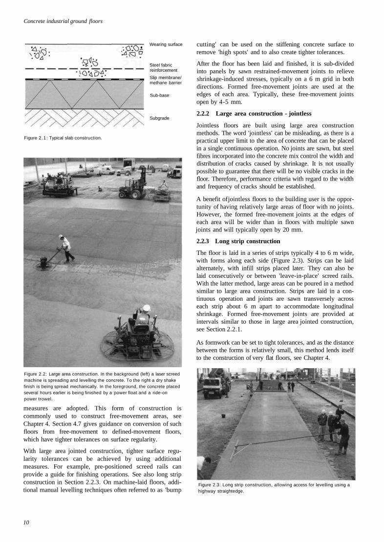
Large floors up to several thousand square metres in area canbe laid in a continuous operation (Figure 2.2). Fixed formsare used only at the edges of the construction at intervals oftypically 50 m. Concrete is discharged into the floor area andspread either manually or by machine. Levels are controlledeither manually using a target staff in conjunction with alaser level transmitter or by direct control of laser-guidedspreading machines.
Over such large areas, it is not possible to control the surfaceregularity in relation to fixed formwork and so there are lim-itations on the accuracy that can be achieved unless specific
establishing specific requirements, having carefully con-sidered each of the aspects described in Chapters 3,4 and 5
benchmarking against existing floors. Where possible ref-erences to these floors should be included in the contractdetails.
There is no single ideal solution for each situation; as in alldesign, compromises have to be reached based on needs andcosts. Also, techniques and materials are being constantlydeveloped to provide better performance and better value.
An ideal floor would be perfectly flat and level and have nojoints. However, there are limits on the dimensional accuracyof any construction and, as concrete shrinks after construction,it is not possible to dispense with joints completely. Joints arealso required because there are practical limitations on the areaof floor that can be constructed at any one time.
At the design stage the designer should plan the joint layout,give indications of the expected performance throughout thelife of the floor, and set out the expected number and per-formance of the joints. Attention should be given to the earlylife of the floor as contraction and shrinkage take place andover the long term. The performance factors to be considered
Previous pageis blank
9
Concrete industrial ground floors
Wearing surface
Steel fabricreinforcement
Slip membrane/methane barrier
Sub-base
Subgrade
Figure 2 .1 : Typical slab construction.
Figure 2.2: Large area construction. In the background (left) a laser screedmachine is spreading and levelling the concrete. To the right a dry shakefinish is being spread mechanically. In the foreground, the concrete placedseveral hours earlier is being finished by a power float and a ride-onpower trowel.
measures are adopted. This form of construction iscommonly used to construct free-movement areas, seeChapter 4. Section 4.7 gives guidance on conversion of suchfloors from free-movement to defined-movement floors,which have tighter tolerances on surface regularity.
With large area jointed construction, tighter surface regu-larity tolerances can be achieved by using additionalmeasures. For example, pre-positioned screed rails canprovide a guide for finishing operations. See also long stripconstruction in Section 2.2.3. On machine-laid floors, addi-tional manual levelling techniques often referred to as 'bump
cutting' can be used on the stiffening concrete surface toremove 'high spots' and to also create tighter tolerances.
After the floor has been laid and finished, it is sub-dividedinto panels by sawn restrained-movement joints to relieveshrinkage-induced stresses, typically on a 6 m grid in bothdirections. Formed free-movement joints are used at theedges of each area. Typically, these free-movement jointsopen by 4-5 mm.
2.2.2 Large area construction - jointless
Jointless floors are built using large area constructionmethods. The word 'jointless' can be misleading, as there is apractical upper limit to the area of concrete that can be placedin a single continuous operation. No joints are sawn, but steelfibres incorporated into the concrete mix control the width anddistribution of cracks caused by shrinkage. It is not usuallypossible to guarantee that there will be no visible cracks in thefloor. Therefore, performance criteria with regard to the widthand frequency of cracks should be established.
A benefit of jointless floors to the building user is the oppor-tunity of having relatively large areas of floor with no joints.However, the formed free-movement joints at the edges ofeach area will be wider than in floors with multiple sawnjoints and will typically open by 20 mm.
2.2.3 Long strip construction
The floor is laid in a series of strips typically 4 to 6 m wide,with forms along each side (Figure 2.3). Strips can be laidalternately, with infill strips placed later. They can also belaid consecutively or between 'leave-in-place' screed rails.With the latter method, large areas can be poured in a methodsimilar to large area construction. Strips are laid in a con-tinuous operation and joints are sawn transversely acrosseach strip about 6 m apart to accommodate longitudinalshrinkage. Formed free-movement joints are provided atintervals similar to those in large area jointed construction,see Section 2.2.1.
As formwork can be set to tight tolerances, and as the distancebetween the forms is relatively small, this method lends itselfto the construction of very flat floors, see Chapter 4.
Figure 2.3: Long strip construction, allowing access for levelling using ahighway straightedge.
10
Floor construction methods and surface characteristics
Floors built in strip construction will have more formedjoints than those built by large area methods, but these jointsare usually designed to be in non-critical positions such asunder storage racking, see Sections 8.7 and 8.10.
2.2.4 Wide bay construction
Wide bay construction is a variation on large area con-struction but with bay widths limited to 12 to 15 m. Limitingthe bay width permits access for the use of 'bump cutting'techniques on the concrete surface to control the surface tol-erances more closely.
2.2.5 Two-layer construction
In two-layer construction, a hardened slab is overlain with asecond layer that is placed between accurately levelledscreed rails at relatively close spacings (typically about 4 m)on the lower slab. This method of construction is morecomplex than others but can be used for very flat floors. Theprinciple is similar to that used for levelling screeds, asdescribed in BS 8204-2 (10).
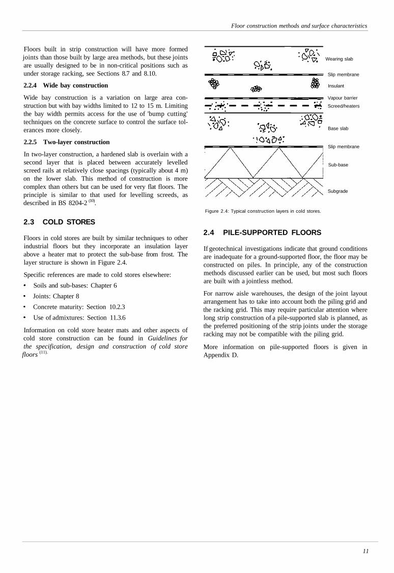
2.3 COLD STORES
Floors in cold stores are built by similar techniques to otherindustrial floors but they incorporate an insulation layerabove a heater mat to protect the sub-base from frost. Thelayer structure is shown in Figure 2.4.
Specific references are made to cold stores elsewhere:
Soils and sub-bases: Chapter 6
Joints: Chapter 8
Concrete maturity: Section 10.2.3
Use of admixtures: Section 11.3.6
Information on cold store heater mats and other aspects ofcold store construction can be found in Guidelines forthe specification, design and construction of cold storefloors (11).
Wearing slab
Slip membrane
Insulant
Vapour barrier
Screed/heaters
Base slab
Slip membrane
Sub-base
Subgrade
Figure 2.4: Typical construction layers in cold stores.
2.4 PILE-SUPPORTED FLOORS
If geotechnical investigations indicate that ground conditionsare inadequate for a ground-supported floor, the floor may beconstructed on piles. In principle, any of the constructionmethods discussed earlier can be used, but most such floorsare built with a jointless method.
For narrow aisle warehouses, the design of the joint layoutarrangement has to take into account both the piling grid andthe racking grid. This may require particular attention wherelong strip construction of a pile-supported slab is planned, asthe preferred positioning of the strip joints under the storageracking may not be compatible with the piling grid.
More information on pile-supported floors is given inAppendix D.
11
3 LOADINGS
3.1 STATIC LOADS
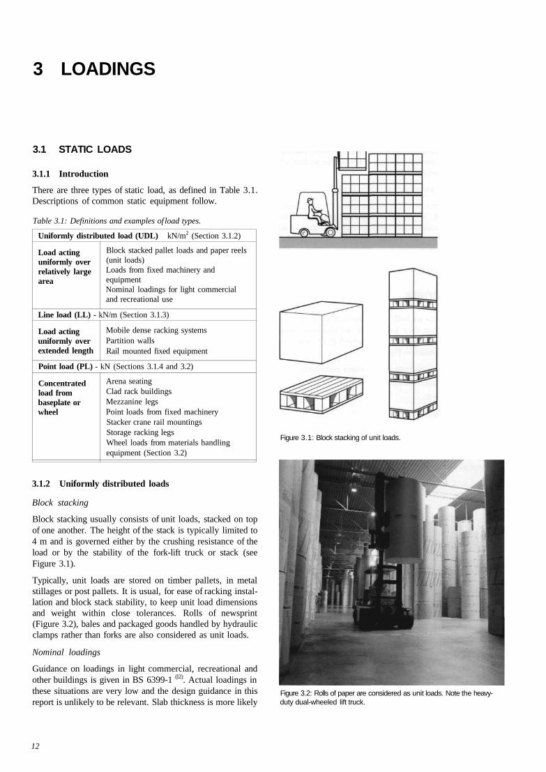
3.1.1 Introduction
There are three types of static load, as defined in Table 3.1.Descriptions of common static equipment follow.
Table 3.1: Definitions and examples of load types.
Uniformly distributed load (UDL) kN/m2 (Section 3.1.2)
Load actinguniformly overrelatively largearea
Block stacked pallet loads and paper reels(unit loads)Loads from fixed machinery andequipmentNominal loadings for light commercialand recreational use
Line load (LL) - kN/m (Section 3.1.3)
Load actinguniformly overextended length
Mobile dense racking systemsPartition wallsRail mounted fixed equipment
Point load (PL) - kN (Sections 3.1.4 and 3.2)
Concentratedload frombaseplate orwheel
Arena seatingClad rack buildingsMezzanine legsPoint loads from fixed machineryStacker crane rail mountingsStorage racking legsWheel loads from materials handlingequipment (Section 3.2)
Figure 3.1: Block stacking of unit loads.
3.1.2 Uniformly distributed loads
Block stacking
Block stacking usually consists of unit loads, stacked on topof one another. The height of the stack is typically limited to4 m and is governed either by the crushing resistance of theload or by the stability of the fork-lift truck or stack (seeFigure 3.1).
Typically, unit loads are stored on timber pallets, in metalstillages or post pallets. It is usual, for ease of racking instal-lation and block stack stability, to keep unit load dimensionsand weight within close tolerances. Rolls of newsprint(Figure 3.2), bales and packaged goods handled by hydraulicclamps rather than forks are also considered as unit loads.
Nominal loadings
Guidance on loadings in light commercial, recreational andother buildings is given in BS 6399-1 (l2). Actual loadings inthese situations are very low and the design guidance in thisreport is unlikely to be relevant. Slab thickness is more likely
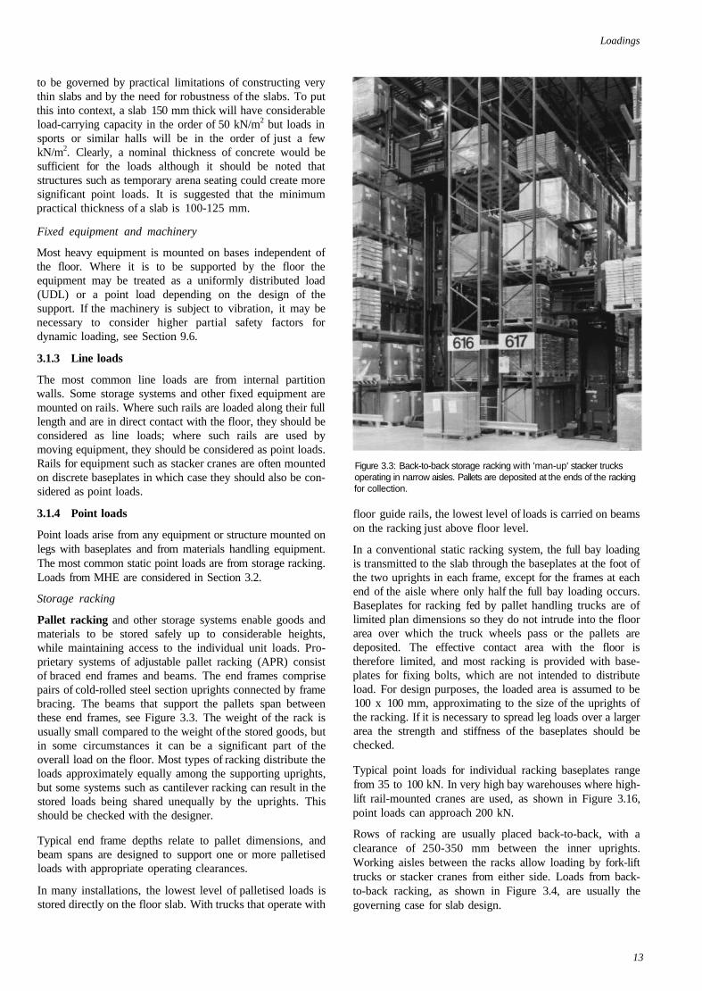
Figure 3.2: Rolls of paper are considered as unit loads. Note the heavy-duty dual-wheeled lift truck.
12
Loadings
to be governed by practical limitations of constructing verythin slabs and by the need for robustness of the slabs. To putthis into context, a slab 150 mm thick will have considerableload-carrying capacity in the order of 50 kN/m2 but loads insports or similar halls will be in the order of just a fewkN/m2. Clearly, a nominal thickness of concrete would besufficient for the loads although it should be noted thatstructures such as temporary arena seating could create moresignificant point loads. It is suggested that the minimumpractical thickness of a slab is 100-125 mm.
Fixed equipment and machinery
Most heavy equipment is mounted on bases independent ofthe floor. Where it is to be supported by the floor theequipment may be treated as a uniformly distributed load(UDL) or a point load depending on the design of thesupport. If the machinery is subject to vibration, it may benecessary to consider higher partial safety factors fordynamic loading, see Section 9.6.
3.1.3 Line loads
The most common line loads are from internal partitionwalls. Some storage systems and other fixed equipment aremounted on rails. Where such rails are loaded along their fulllength and are in direct contact with the floor, they should beconsidered as line loads; where such rails are used bymoving equipment, they should be considered as point loads.Rails for equipment such as stacker cranes are often mountedon discrete baseplates in which case they should also be con-sidered as point loads.
3.1.4 Point loads
Point loads arise from any equipment or structure mounted onlegs with baseplates and from materials handling equipment.The most common static point loads are from storage racking.Loads from MHE are considered in Section 3.2.
Storage racking
Pallet racking and other storage systems enable goods andmaterials to be stored safely up to considerable heights,while maintaining access to the individual unit loads. Pro-prietary systems of adjustable pallet racking (APR) consistof braced end frames and beams. The end frames comprisepairs of cold-rolled steel section uprights connected by framebracing. The beams that support the pallets span betweenthese end frames, see Figure 3.3. The weight of the rack isusually small compared to the weight of the stored goods, butin some circumstances it can be a significant part of theoverall load on the floor. Most types of racking distribute theloads approximately equally among the supporting uprights,but some systems such as cantilever racking can result in thestored loads being shared unequally by the uprights. Thisshould be checked with the designer.
Typical end frame depths relate to pallet dimensions, andbeam spans are designed to support one or more palletisedloads with appropriate operating clearances.
In many installations, the lowest level of palletised loads isstored directly on the floor slab. With trucks that operate with
Figure 3.3: Back-to-back storage racking with 'man-up' stacker trucksoperating in narrow aisles. Pallets are deposited at the ends of the rackingfor collection.
floor guide rails, the lowest level of loads is carried on beamson the racking just above floor level.
In a conventional static racking system, the full bay loadingis transmitted to the slab through the baseplates at the foot ofthe two uprights in each frame, except for the frames at eachend of the aisle where only half the full bay loading occurs.Baseplates for racking fed by pallet handling trucks are oflimited plan dimensions so they do not intrude into the floorarea over which the truck wheels pass or the pallets aredeposited. The effective contact area with the floor istherefore limited, and most racking is provided with base-plates for fixing bolts, which are not intended to distributeload. For design purposes, the loaded area is assumed to be100 x 100 mm, approximating to the size of the uprights ofthe racking. If it is necessary to spread leg loads over a largerarea the strength and stiffness of the baseplates should bechecked.
Typical point loads for individual racking baseplates rangefrom 35 to 100 kN. In very high bay warehouses where high-lift rail-mounted cranes are used, as shown in Figure 3.16,point loads can approach 200 kN.
Rows of racking are usually placed back-to-back, with aclearance of 250-350 mm between the inner uprights.Working aisles between the racks allow loading by fork-lifttrucks or stacker cranes from either side. Loads from back-to-back racking, as shown in Figure 3.4, are usually thegoverning case for slab design.
13
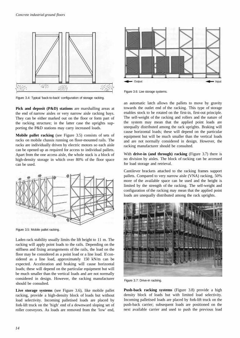
Concrete industrial ground floors
Figure 3.4: Typical 'back-to-back' configuration of storage racking.
Pick and deposit (P&D) stations are marshalling areas atthe end of narrow aisles or very narrow aisle racking bays.They can be either marked out on the floor or form part ofthe racking structure; in the latter case the uprights sup-porting the P&D stations may carry increased loads.
Mobile pallet racking (see Figure 3.5) consists of sets ofracks on mobile chassis running on floor-mounted rails. Theracks are individually driven by electric motors so each aislecan be opened up as required for access to individual pallets.Apart from the one access aisle, the whole stack is a block ofhigh-density storage in which over 80% of the floor spacecan be used.
Figure 3.5: Mobile pallet racking.
Laden rack stability usually limits the lift height to 11 m. Theracking will apply point loads to the rails. Depending on thestiffness and fixing arrangements of the rails, the load on thefloor may be considered as a point load or a line load. If con-sidered as a line load, approximately 150 kN/m can beexpected. Acceleration and braking will cause horizontalloads; these will depend on the particular equipment but willbe much smaller than the vertical loads and are not normallyconsidered in design. However, the racking manufacturershould be consulted.
Live storage systems (see Figure 3.6), like mobile palletracking, provide a high-density block of loads but withoutload selectivity. Incoming palletised loads are placed byfork-lift truck on the 'high' end of a downward sloping set ofroller conveyors. As loads are removed from the 'low' end,
Figure 3.6: Live storage systems.
Input
an automatic latch allows the pallets to move by gravitytowards the outlet end of the racking. This type of storageenables stock to be rotated on the first-in, first-out principle.The self-weight of the racking and rollers and the nature ofthe system may mean that the applied point loads areunequally distributed among the rack uprights. Braking willcause horizontal loads; these will depend on the particularequipment but will be much smaller than the vertical loadsand are not normally considered in design. However, theracking manufacturer should be consulted.
With drive-in (and through) racking (Figure 3.7) there isno division by aisles. The block of racking can be accessedfor load storage and retrieval.
Cantilever brackets attached to the racking frames supportpallets. Compared to very narrow aisle (VNA) racking, 50%more of the available space can be used and the height islimited by the strength of the racking. The self-weight andconfiguration of the racking may mean that the applied pointloads are unequally distributed among the rack uprights.
Figure 3.7: Drive-in racking.
Push-back racking systems (Figure 3.8) provide a highdensity block of loads but with limited load selectivity.Incoming palletised loads are placed by fork-lift truck on thepush-back carrier; subsequent loads are positioned on thenext available carrier and used to push the previous load
14
Output
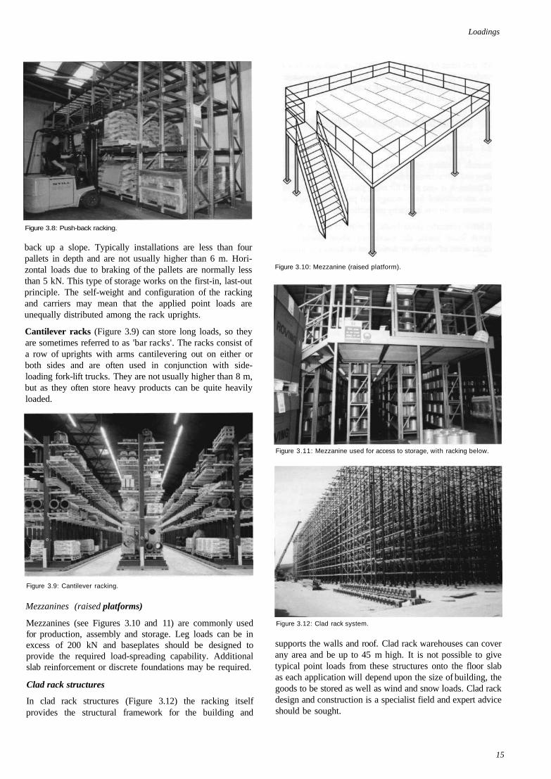
Loadings
Figure 3.8: Push-back racking.
back up a slope. Typically installations are less than fourpallets in depth and are not usually higher than 6 m. Hori-zontal loads due to braking of the pallets are normally lessthan 5 kN. This type of storage works on the first-in, last-outprinciple. The self-weight and configuration of the rackingand carriers may mean that the applied point loads areunequally distributed among the rack uprights.
Cantilever racks (Figure 3.9) can store long loads, so theyare sometimes referred to as 'bar racks'. The racks consist ofa row of uprights with arms cantilevering out on either orboth sides and are often used in conjunction with side-loading fork-lift trucks. They are not usually higher than 8 m,but as they often store heavy products can be quite heavilyloaded.
Figure 3.9: Cantilever racking.
Mezzanines (raised platforms)
Mezzanines (see Figures 3.10 and 11) are commonly usedfor production, assembly and storage. Leg loads can be inexcess of 200 kN and baseplates should be designed toprovide the required load-spreading capability. Additionalslab reinforcement or discrete foundations may be required.
Clad rack structures
In clad rack structures (Figure 3.12) the racking itselfprovides the structural framework for the building and
Figure 3.10: Mezzanine (raised platform).
Figure 3.11: Mezzanine used for access to storage, with racking below.
Figure 3.12: Clad rack system.
supports the walls and roof. Clad rack warehouses can coverany area and be up to 45 m high. It is not possible to givetypical point loads from these structures onto the floor slabas each application will depend upon the size of building, thegoods to be stored as well as wind and snow loads. Clad rackdesign and construction is a specialist field and expert adviceshould be sought.
15
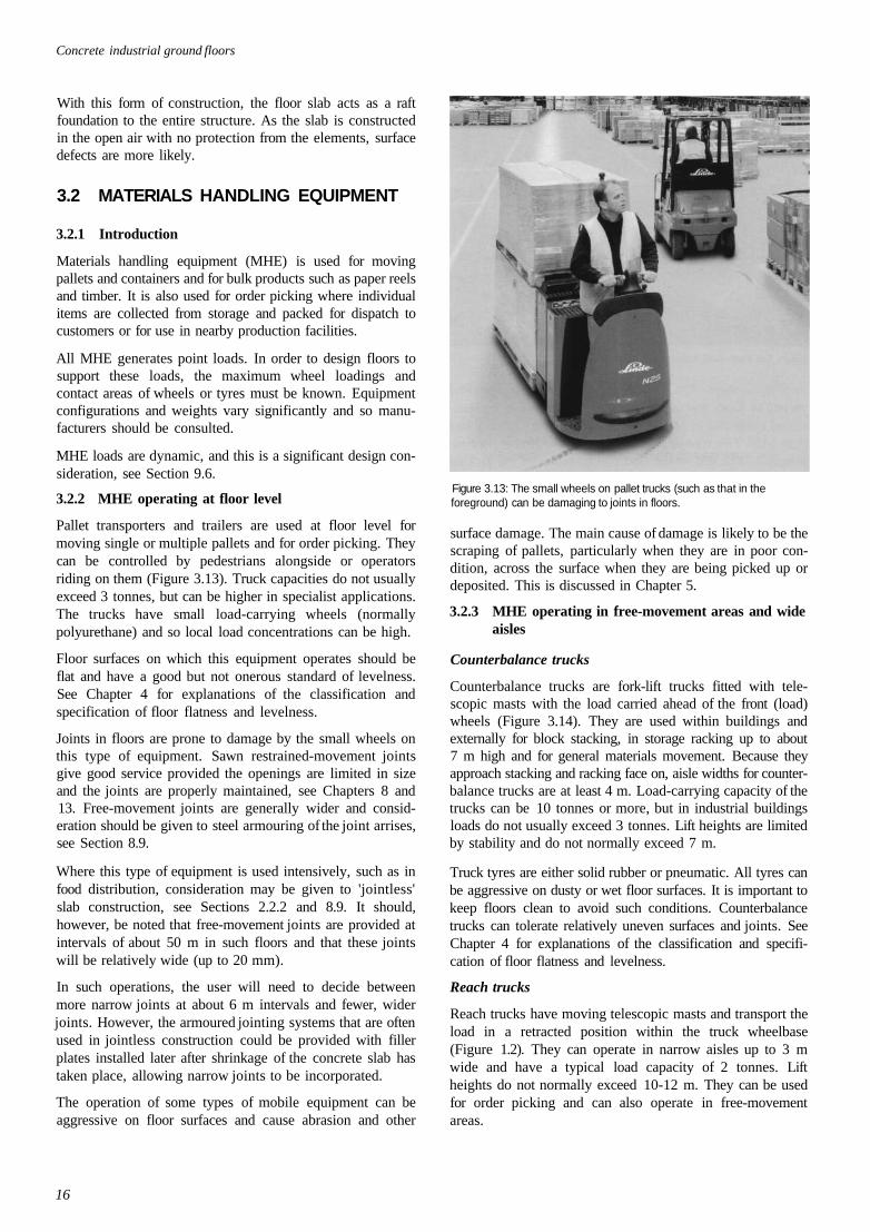
Concrete industrial ground floors
With this form of construction, the floor slab acts as a raftfoundation to the entire structure. As the slab is constructedin the open air with no protection from the elements, surfacedefects are more likely.
3.2 MATERIALS HANDLING EQUIPMENT
3.2.1 Introduction
Materials handling equipment (MHE) is used for movingpallets and containers and for bulk products such as paper reelsand timber. It is also used for order picking where individualitems are collected from storage and packed for dispatch tocustomers or for use in nearby production facilities.
All MHE generates point loads. In order to design floors tosupport these loads, the maximum wheel loadings andcontact areas of wheels or tyres must be known. Equipmentconfigurations and weights vary significantly and so manu-facturers should be consulted.
MHE loads are dynamic, and this is a significant design con-sideration, see Section 9.6.
3.2.2 MHE operating at floor level
Pallet transporters and trailers are used at floor level formoving single or multiple pallets and for order picking. Theycan be controlled by pedestrians alongside or operatorsriding on them (Figure 3.13). Truck capacities do not usuallyexceed 3 tonnes, but can be higher in specialist applications.The trucks have small load-carrying wheels (normallypolyurethane) and so local load concentrations can be high.
Floor surfaces on which this equipment operates should beflat and have a good but not onerous standard of levelness.See Chapter 4 for explanations of the classification andspecification of floor flatness and levelness.
Joints in floors are prone to damage by the small wheels onthis type of equipment. Sawn restrained-movement jointsgive good service provided the openings are limited in sizeand the joints are properly maintained, see Chapters 8 and13. Free-movement joints are generally wider and consid-eration should be given to steel armouring of the joint arrises,see Section 8.9.
Where this type of equipment is used intensively, such as infood distribution, consideration may be given to 'jointless'slab construction, see Sections 2.2.2 and 8.9. It should,however, be noted that free-movement joints are provided atintervals of about 50 m in such floors and that these jointswill be relatively wide (up to 20 mm).
In such operations, the user will need to decide betweenmore narrow joints at about 6 m intervals and fewer, widerjoints. However, the armoured jointing systems that are oftenused in jointless construction could be provided with fillerplates installed later after shrinkage of the concrete slab hastaken place, allowing narrow joints to be incorporated.
The operation of some types of mobile equipment can beaggressive on floor surfaces and cause abrasion and other
Figure 3.13: The small wheels on pallet trucks (such as that in theforeground) can be damaging to joints in floors.
surface damage. The main cause of damage is likely to be thescraping of pallets, particularly when they are in poor con-dition, across the surface when they are being picked up ordeposited. This is discussed in Chapter 5.
3.2.3 MHE operating in free-movement areas and wideaisles
Counterbalance trucks
Counterbalance trucks are fork-lift trucks fitted with tele-scopic masts with the load carried ahead of the front (load)wheels (Figure 3.14). They are used within buildings andexternally for block stacking, in storage racking up to about7 m high and for general materials movement. Because theyapproach stacking and racking face on, aisle widths for counter-balance trucks are at least 4 m. Load-carrying capacity of thetrucks can be 10 tonnes or more, but in industrial buildingsloads do not usually exceed 3 tonnes. Lift heights are limitedby stability and do not normally exceed 7 m.
Truck tyres are either solid rubber or pneumatic. All tyres canbe aggressive on dusty or wet floor surfaces. It is important tokeep floors clean to avoid such conditions. Counterbalancetrucks can tolerate relatively uneven surfaces and joints. SeeChapter 4 for explanations of the classification and specifi-cation of floor flatness and levelness.
Reach trucks
Reach trucks have moving telescopic masts and transport theload in a retracted position within the truck wheelbase(Figure 1.2). They can operate in narrow aisles up to 3 mwide and have a typical load capacity of 2 tonnes. Liftheights do not normally exceed 10-12 m. They can be usedfor order picking and can also operate in free-movementareas.
16
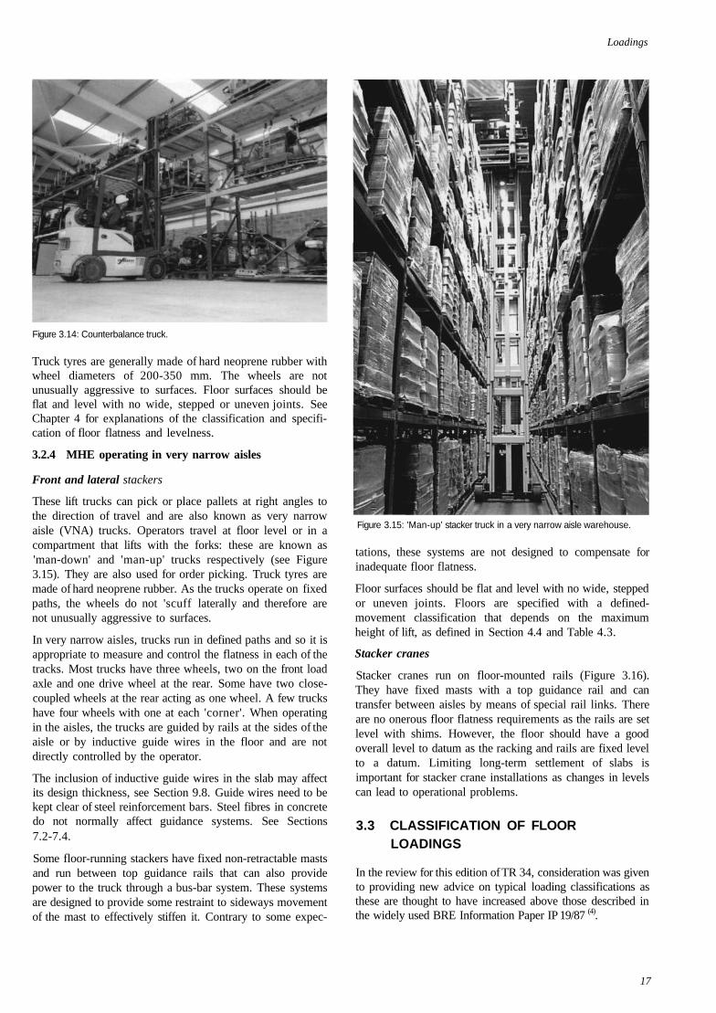
Loadings
Figure 3.14: Counterbalance truck.
Truck tyres are generally made of hard neoprene rubber withwheel diameters of 200-350 mm. The wheels are notunusually aggressive to surfaces. Floor surfaces should beflat and level with no wide, stepped or uneven joints. SeeChapter 4 for explanations of the classification and specifi-cation of floor flatness and levelness.
3.2.4 MHE operating in very narrow aisles
Front and lateral stackers
These lift trucks can pick or place pallets at right angles tothe direction of travel and are also known as very narrowaisle (VNA) trucks. Operators travel at floor level or in acompartment that lifts with the forks: these are known as'man-down' and 'man-up' trucks respectively (see Figure3.15). They are also used for order picking. Truck tyres aremade of hard neoprene rubber. As the trucks operate on fixedpaths, the wheels do not 'scuff laterally and therefore arenot unusually aggressive to surfaces.
In very narrow aisles, trucks run in defined paths and so it isappropriate to measure and control the flatness in each of thetracks. Most trucks have three wheels, two on the front loadaxle and one drive wheel at the rear. Some have two close-coupled wheels at the rear acting as one wheel. A few truckshave four wheels with one at each 'corner'. When operatingin the aisles, the trucks are guided by rails at the sides of theaisle or by inductive guide wires in the floor and are notdirectly controlled by the operator.
The inclusion of inductive guide wires in the slab may affectits design thickness, see Section 9.8. Guide wires need to bekept clear of steel reinforcement bars. Steel fibres in concretedo not normally affect guidance systems. See Sections7.2-7.4.
Some floor-running stackers have fixed non-retractable mastsand run between top guidance rails that can also providepower to the truck through a bus-bar system. These systemsare designed to provide some restraint to sideways movementof the mast to effectively stiffen it. Contrary to some expec-
Figure 3.15: 'Man-up' stacker truck in a very narrow aisle warehouse.
tations, these systems are not designed to compensate forinadequate floor flatness.
Floor surfaces should be flat and level with no wide, steppedor uneven joints. Floors are specified with a defined-movement classification that depends on the maximumheight of lift, as defined in Section 4.4 and Table 4.3.
Stacker cranes
Stacker cranes run on floor-mounted rails (Figure 3.16).They have fixed masts with a top guidance rail and cantransfer between aisles by means of special rail links. Thereare no onerous floor flatness requirements as the rails are setlevel with shims. However, the floor should have a goodoverall level to datum as the racking and rails are fixed levelto a datum. Limiting long-term settlement of slabs isimportant for stacker crane installations as changes in levelscan lead to operational problems.
3.3 CLASSIFICATION OF FLOORLOADINGS
In the review for this edition of TR 34, consideration was givento providing new advice on typical loading classifications asthese are thought to have increased above those described inthe widely used BRE Information Paper IP 19/87 (4).
17
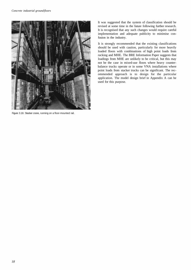
Concrete industrial ground floors
It was suggested that the system of classification should berevised at some time in the future following further research.It is recognised that any such changes would require carefulimplementation and adequate publicity to minimise con-fusion in the industry.
It is strongly recommended that the existing classificationsshould be used with caution, particularly for more heavilyloaded floors with combinations of high point loads fromracking and MHE. The BRE Information Paper suggests thatloadings from MHE are unlikely to be critical, but this maynot be the case in mixed-use floors where heavy counter-balance trucks operate or in some VNA installations wherepoint loads from stacker trucks can be significant. The rec-ommended approach is to design for the particularapplication. The model design brief in Appendix A can beused for this purpose.
Figure 3.16: Stacker crane, running on a floor-mounted rail.
18
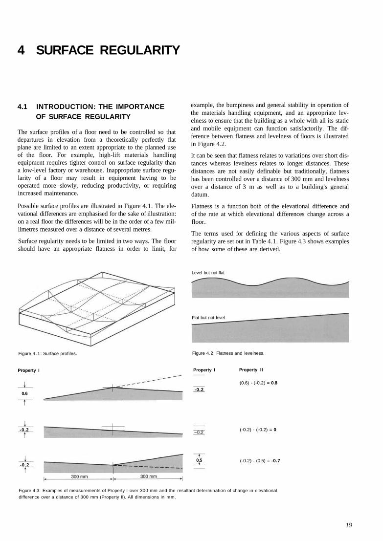
4 SURFACE REGULARITY
4.1 INTRODUCTION: THE IMPORTANCEOF SURFACE REGULARITY
The surface profiles of a floor need to be controlled so thatdepartures in elevation from a theoretically perfectly flatplane are limited to an extent appropriate to the planned useof the floor. For example, high-lift materials handlingequipment requires tighter control on surface regularity thana low-level factory or warehouse. Inappropriate surface regu-larity of a floor may result in equipment having to beoperated more slowly, reducing productivity, or requiringincreased maintenance.
Possible surface profiles are illustrated in Figure 4.1. The ele-vational differences are emphasised for the sake of illustration:on a real floor the differences will be in the order of a few mil-limetres measured over a distance of several metres.
Surface regularity needs to be limited in two ways. The floorshould have an appropriate flatness in order to limit, for
example, the bumpiness and general stability in operation ofthe materials handling equipment, and an appropriate lev-elness to ensure that the building as a whole with all its staticand mobile equipment can function satisfactorily. The dif-ference between flatness and levelness of floors is illustratedin Figure 4.2.
It can be seen that flatness relates to variations over short dis-tances whereas levelness relates to longer distances. Thesedistances are not easily definable but traditionally, flatnesshas been controlled over a distance of 300 mm and levelnessover a distance of 3 m as well as to a building's generaldatum.
Flatness is a function both of the elevational difference andof the rate at which elevational differences change across afloor.
The terms used for defining the various aspects of surfaceregularity are set out in Table 4.1. Figure 4.3 shows examplesof how some of these are derived.
Level but not flat
Figure 4 .1 : Surface profiles.
Flat but not level
Figure 4.2: Flatness and levelness.
Property I Property II
(0.6) - (-0.2) = 0.8
(-0.2) - (-0.2) = 0
(-0.2) - (0.5) = -0.7
Figure 4.3: Examples of measurements of Property I over 300 mm and the resultant determination of change in elevationaldifference over a distance of 300 mm (Property II). All dimensions in mm.
19
Property I
0.6
-0.2
-0.2
-0.2
0.5
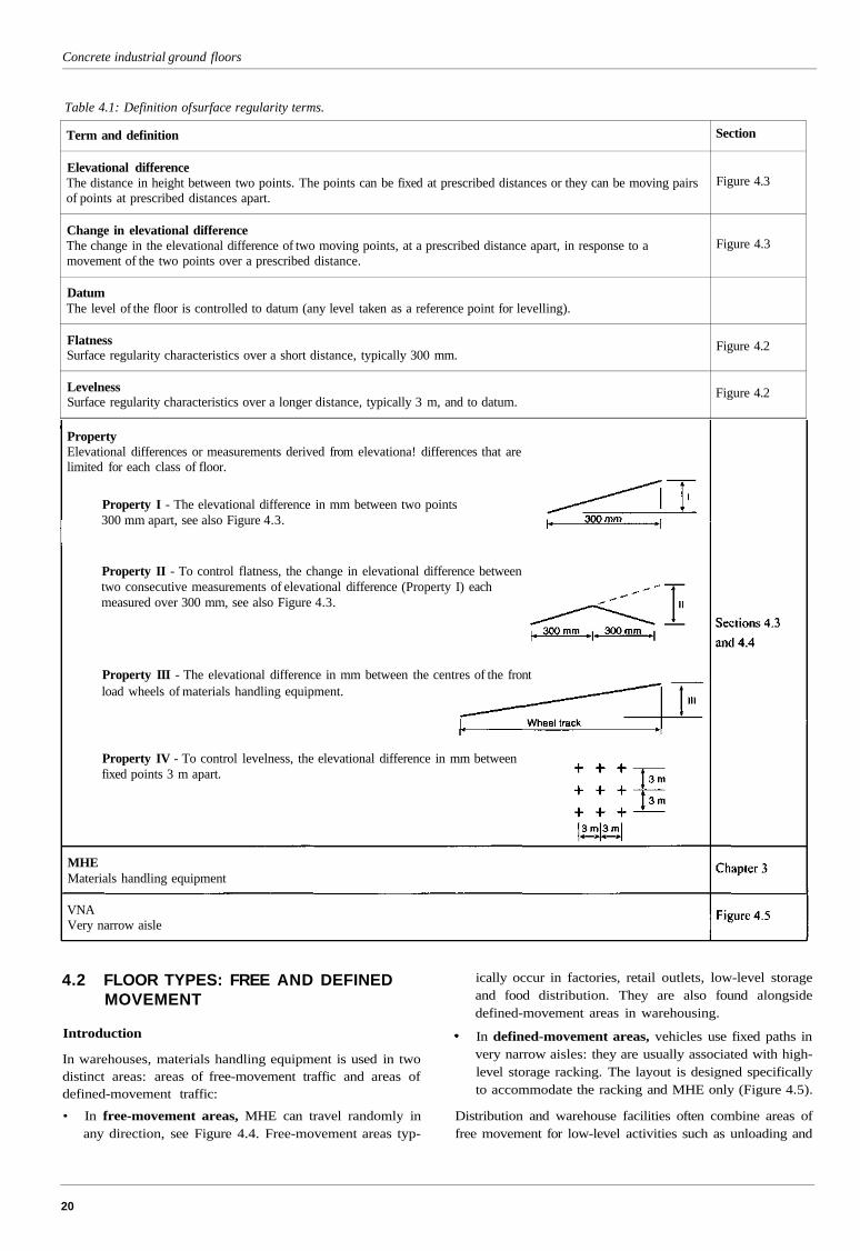
Concrete industrial ground floors
Table 4.1: Definition of surface regularity terms.
Term and definition
Elevational differenceThe distance in height between two points. The points can be fixed at prescribed distances or they can be moving pairsof points at prescribed distances apart.
Change in elevational differenceThe change in the elevational difference of two moving points, at a prescribed distance apart, in response to amovement of the two points over a prescribed distance.
DatumThe level of the floor is controlled to datum (any level taken as a reference point for levelling).
FlatnessSurface regularity characteristics over a short distance, typically 300 mm.
LevelnessSurface regularity characteristics over a longer distance, typically 3 m, and to datum.
Section
Figure 4.3
Figure 4.3
Figure 4.2
Figure 4.2
PropertyElevational differences or measurements derived from elevationa! differences that arelimited for each class of floor.
Property I - The elevational difference in mm between two points300 mm apart, see also Figure 4.3.
Property II - To control flatness, the change in elevational difference betweentwo consecutive measurements of elevational difference (Property I) eachmeasured over 300 mm, see also Figure 4.3.
Property III - The elevational difference in mm between the centres of the frontload wheels of materials handling equipment.
Property IV - To control levelness, the elevational difference in mm betweenfixed points 3 m apart.
MHEMaterials handling equipment
VNAVery narrow aisle
4.2 FLOOR TYPES: FREE AND DEFINEDMOVEMENT
Introduction
In warehouses, materials handling equipment is used in twodistinct areas: areas of free-movement traffic and areas ofdefined-movement traffic:
• In free-movement areas, MHE can travel randomly inany direction, see Figure 4.4. Free-movement areas typ-
ically occur in factories, retail outlets, low-level storageand food distribution. They are also found alongsidedefined-movement areas in warehousing.
In defined-movement areas, vehicles use fixed paths invery narrow aisles: they are usually associated with high-level storage racking. The layout is designed specificallyto accommodate the racking and MHE only (Figure 4.5).
Distribution and warehouse facilities often combine areas offree movement for low-level activities such as unloading and
20
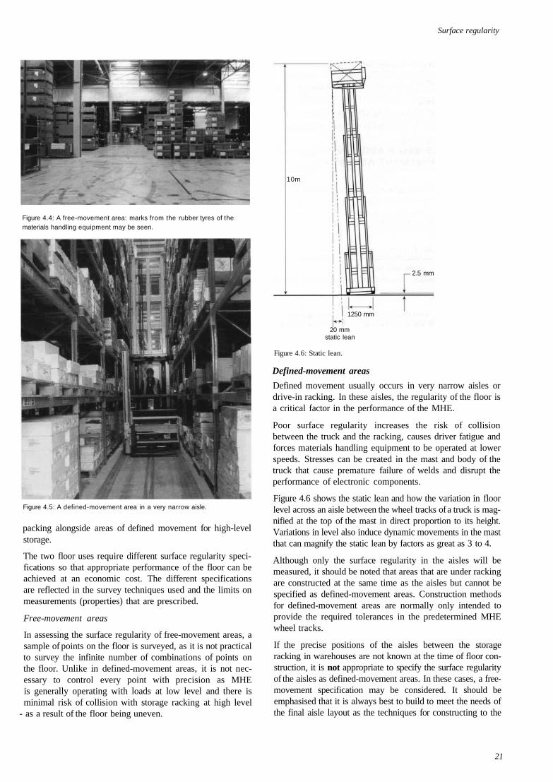
Surface regularity
Figure 4.4: A free-movement area: marks from the rubber tyres of thematerials handling equipment may be seen.
Figure 4.5: A defined-movement area in a very narrow aisle.
packing alongside areas of defined movement for high-levelstorage.
The two floor uses require different surface regularity speci-fications so that appropriate performance of the floor can beachieved at an economic cost. The different specificationsare reflected in the survey techniques used and the limits onmeasurements (properties) that are prescribed.
Free-movement areas
In assessing the surface regularity of free-movement areas, asample of points on the floor is surveyed, as it is not practicalto survey the infinite number of combinations of points onthe floor. Unlike in defined-movement areas, it is not nec-essary to control every point with precision as MHEis generally operating with loads at low level and there isminimal risk of collision with storage racking at high level
- as a result of the floor being uneven.
10m
2.5 mm
1250 mm
20 mmstatic lean
Figure 4.6: Static lean.
Defined-movement areas
Defined movement usually occurs in very narrow aisles ordrive-in racking. In these aisles, the regularity of the floor isa critical factor in the performance of the MHE.
Poor surface regularity increases the risk of collisionbetween the truck and the racking, causes driver fatigue andforces materials handling equipment to be operated at lowerspeeds. Stresses can be created in the mast and body of thetruck that cause premature failure of welds and disrupt theperformance of electronic components.
Figure 4.6 shows the static lean and how the variation in floorlevel across an aisle between the wheel tracks of a truck is mag-nified at the top of the mast in direct proportion to its height.Variations in level also induce dynamic movements in the mastthat can magnify the static lean by factors as great as 3 to 4.
Although only the surface regularity in the aisles will bemeasured, it should be noted that areas that are under rackingare constructed at the same time as the aisles but cannot bespecified as defined-movement areas. Construction methodsfor defined-movement areas are normally only intended toprovide the required tolerances in the predetermined MHEwheel tracks.
If the precise positions of the aisles between the storageracking in warehouses are not known at the time of floor con-struction, it is not appropriate to specify the surface regularityof the aisles as defined-movement areas. In these cases, a free-movement specification may be considered. It should beemphasised that it is always best to build to meet the needs ofthe final aisle layout as the techniques for constructing to the
21
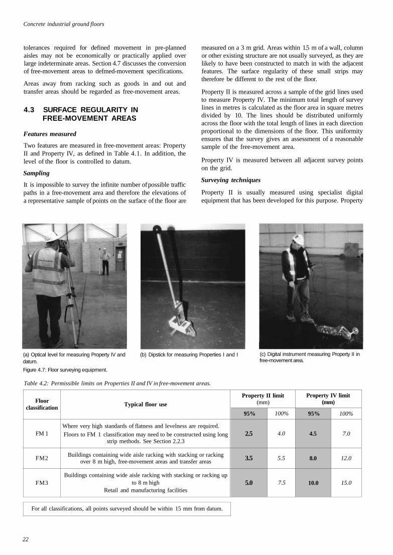
Concrete industrial ground floors
tolerances required for defined movement in pre-plannedaisles may not be economically or practically applied overlarge indeterminate areas. Section 4.7 discusses the conversionof free-movement areas to defmed-movement specifications.
Areas away from racking such as goods in and out andtransfer areas should be regarded as free-movement areas.
4.3 SURFACE REGULARITY INFREE-MOVEMENT AREAS
Features measured
Two features are measured in free-movement areas: PropertyII and Property IV, as defined in Table 4.1. In addition, thelevel of the floor is controlled to datum.
Sampling
It is impossible to survey the infinite number of possible trafficpaths in a free-movement area and therefore the elevations ofa representative sample of points on the surface of the floor are
measured on a 3 m grid. Areas within 1.5 m of a wall, columnor other existing structure are not usually surveyed, as they arelikely to have been constructed to match in with the adjacentfeatures. The surface regularity of these small strips maytherefore be different to the rest of the floor.
Property II is measured across a sample of the grid lines usedto measure Property IV. The minimum total length of surveylines in metres is calculated as the floor area in square metresdivided by 10. The lines should be distributed uniformlyacross the floor with the total length of lines in each directionproportional to the dimensions of the floor. This uniformityensures that the survey gives an assessment of a reasonablesample of the free-movement area.
Property IV is measured between all adjacent survey pointson the grid.
Surveying techniques
Property II is usually measured using specialist digitalequipment that has been developed for this purpose. Property
(a) Optical level for measuring Property IV and (b) Dipstick for measuring Properties I and Idatum.
Figure 4.7: Floor surveying equipment.
Table 4.2: Permissible limits on Properties II and IV in free-movement areas.
(c) Digital instrument measuring Property II infree-movement area.
Floorclassification
FM 1
FM2
FM3
Typical floor use
Where very high standards of flatness and levelness are required.
Floors to FM 1 classification may need to be constructed using longstrip methods. See Section 2.2.3
Buildings containing wide aisle racking with stacking or rackingover 8 m high, free-movement areas and transfer areas
Buildings containing wide aisle racking with stacking or racking upto 8 m high
Retail and manufacturing facilities
For all classifications, all points surveyed should be within 15 mm from datum.
Property II limit(mm)
95%
2.5
3.5
5.0
100%
4.0
5.5
7.5
Property IV limit(mm)
95%
4.5
8.0
10.0
100%
7.0
12.0
15.0
22
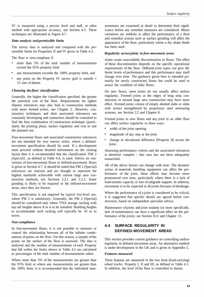
Surface regularity
IV is measured using a precise level and staff, or othermethod with appropriate accuracy, see Section 4.5. Thesetechniques are illustrated in Figure 4.7.
Data analysis and permissible limits
The survey data is analysed and compared with the per-missible limits for Properties II and IV given in Table 4.2.
The floor is non-compliant if:
more than 5% of the total number of measurementsexceed the 95% property limit
any measurement exceeds the 100% property limit, and
any point on the Property IV survey grid is outside15 mm of datum.
Choosing the floor classification
Generally, the higher the classification specified, the greaterthe potential cost of the floor. Requirements for tighterflatness tolerances may also lead to construction methodswith more formed joints, see Chapter 2. However, con-struction techniques and their associated tolerances areconstantly developing and contractors should be consulted tofind the best combination of construction technique (partic-ularly the jointing plan), surface regularity and cost to suitthe planned use.
Free-movement floors and associated construction tolerancesare not intended for very narrow aisles, where a defined-movement specification should be used. If a developmentmust proceed without detailed information on the rackinglayout then it is recommended that the classification 'FM 2(Special)', as defined in Table 4.4, is used. Advice on con-version of free-movement floors to defined-movement floorsis given in Section 4.7. It should be noted that FM 2 (Special)tolerances are onerous and are thought to represent thehighest standards achievable with current large area con-struction methods, see Sections 2.2.1 and 2.2.2. Somegrinding is likely to be required in the defined-movementareas, once they are known.
This specification is not required for typical low-level use,where FM 2 is satisfactory. Generally, the FM 2 (Special)should be considered only where VNA storage racking withtop rail heights above 8 m is to be installed. Building heightsto accommodate such racking will typically be 10 m toeaves.
Non-compliance
In free-movement floors, it is not possible to measure orcontrol the relationship between all of the infinite combi-nations of points on the floor. For this reason, a sample of thepoints on the surface of the floor is assessed. The data isanalysed and the number of measurements of each Propertythat fall within the limits shown in Table 4.2 are calculatedas percentages of the total number of measurements taken.
Where more than 5% of the measurements are greater thanthe 95% limit or where any measurements are greater thanthe 100% limit, it is recommended that the individual mea-
surements are examined in detail to determine their signif-icance before any remedial measures are considered. Minorvariations are unlikely to affect the performance of a floorand remedial actions such as surface grinding will affect theappearance of the floor, particularly where a dry shake finishhas been used.
Regularity across joints in free-movement areas
Joints create unavoidable discontinuities in floors. The effectof these discontinuities depends on the specific operationalrequirements of the floor. Different joint types can give dif-ferent levels of performance and this performance may itselfchange over time. The guidance given here is intended pri-marily for newly constructed floors but could be used toassess the condition of older floors.
On new floors, sawn joints do not usually affect surfaceregularity. Formed joints at the edges of long strip con-struction or around large area construction may have moreeffect. Formed joints consist of simply abutted slabs or slabswith arrises strengthened by proprietary steel armouringsystems, see Section 2.2 and Chapter 8.
Formed joints in new floors and any joint in an older floorcan affect surface regularity in three ways.
width of the joint opening
magnitude of any step at the joint
change in elevational difference (Property II) across thejoint.
Assessing performance criteria and the associated tolerancesis therefore complex - this area has not been adequatelyresearched.
All of the above factors can change with time. The dynamicaction of materials handling equipment can affect the per-formance of the joint; these effects may become morepronounced over time, particularly where there is a lack ofload-transfer capacity or loss of subgrade support. In addition,movement is to be expected at all joints because of shrinkage.
Where the performance of a joint is considered to be critical,it is suggested that specific details are agreed before con-struction, based on independent specialist advice.
Maintenance of joints and joint sealants (or more specifically,lack of maintenance) can have a significant effect on the per-formance of the joints; see Section 8.12 and Chapter 13.
4.4 SURFACE REGULARITY INDEFINED-MOVEMENT AREAS
This section provides current guidance on controlling surfaceregularity in defined-movement areas. An alternative methodis under development in the UK and is given in Appendix C.
Features measured
Three features are measured in the two front (load-carrying)wheel tracks: Property I, II and III, as defined in Table 4.1.In addition, the level of the floor is controlled to datum.
23
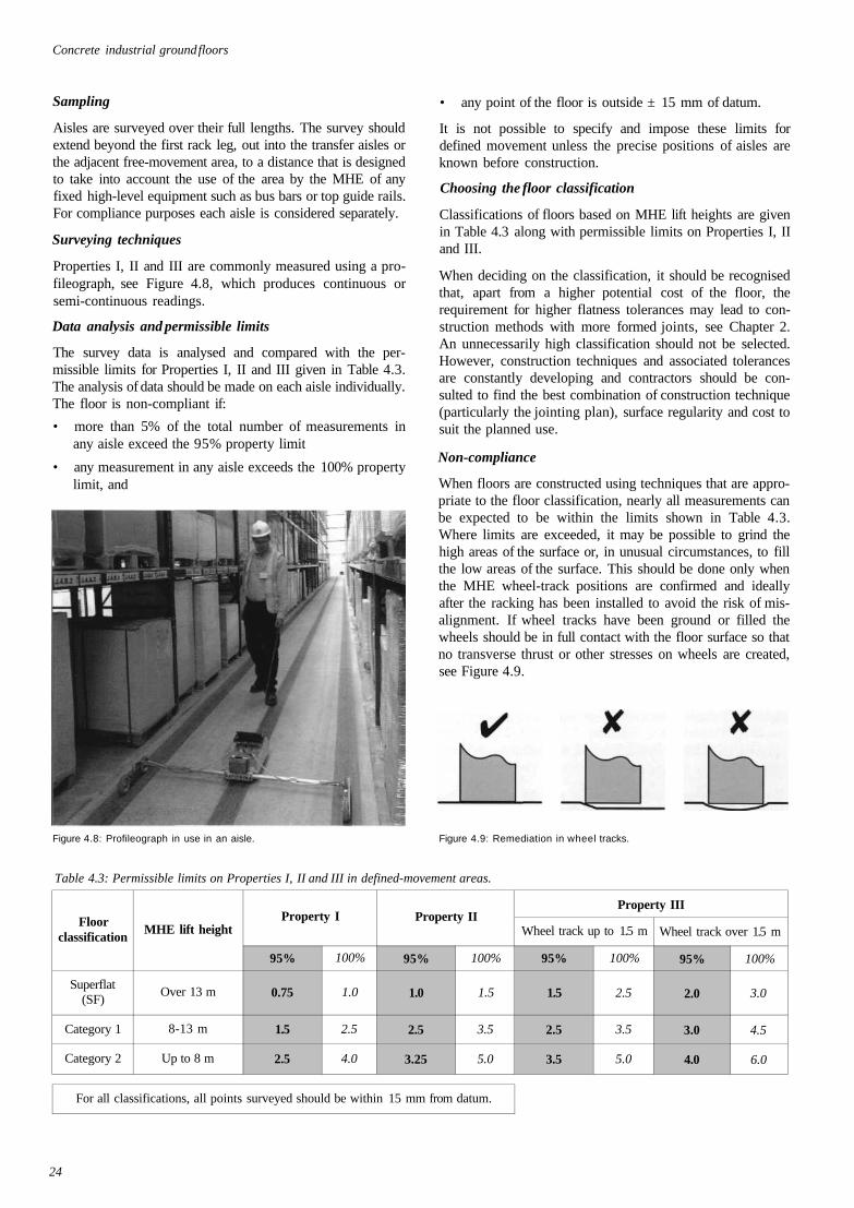
Concrete industrial ground floors
Sampling
Aisles are surveyed over their full lengths. The survey shouldextend beyond the first rack leg, out into the transfer aisles orthe adjacent free-movement area, to a distance that is designedto take into account the use of the area by the MHE of anyfixed high-level equipment such as bus bars or top guide rails.For compliance purposes each aisle is considered separately.
Surveying techniques
Properties I, II and III are commonly measured using a pro-fileograph, see Figure 4.8, which produces continuous orsemi-continuous readings.
Data analysis and permissible limits
The survey data is analysed and compared with the per-missible limits for Properties I, II and III given in Table 4.3.The analysis of data should be made on each aisle individually.The floor is non-compliant if:
• more than 5% of the total number of measurements inany aisle exceed the 95% property limit
• any measurement in any aisle exceeds the 100% propertylimit, and
• any point of the floor is outside ± 15 mm of datum.
It is not possible to specify and impose these limits fordefined movement unless the precise positions of aisles areknown before construction.
Choosing the floor classification
Classifications of floors based on MHE lift heights are givenin Table 4.3 along with permissible limits on Properties I, IIand III.
When deciding on the classification, it should be recognisedthat, apart from a higher potential cost of the floor, therequirement for higher flatness tolerances may lead to con-struction methods with more formed joints, see Chapter 2.An unnecessarily high classification should not be selected.However, construction techniques and associated tolerancesare constantly developing and contractors should be con-sulted to find the best combination of construction technique(particularly the jointing plan), surface regularity and cost tosuit the planned use.
Non-compliance
When floors are constructed using techniques that are appro-priate to the floor classification, nearly all measurements canbe expected to be within the limits shown in Table 4.3.Where limits are exceeded, it may be possible to grind thehigh areas of the surface or, in unusual circumstances, to fillthe low areas of the surface. This should be done only whenthe MHE wheel-track positions are confirmed and ideallyafter the racking has been installed to avoid the risk of mis-alignment. If wheel tracks have been ground or filled thewheels should be in full contact with the floor surface so thatno transverse thrust or other stresses on wheels are created,see Figure 4.9.
Figure 4.8: Profileograph in use in an aisle. Figure 4.9: Remediation in wheel tracks.
Table 4.3: Permissible limits on Properties I, II and III in defined-movement areas.
Floorclassification
Superflat(SF)
Category 1
Category 2
MHE lift height
Over 13 m
8-13 m
Up to 8 m
Property I
95%
0.75
1.5
2.5
100%
1.0
2.5
4.0
Property II
95%
1.0
2.5
3.25
100%
1.5
3.5
5.0
For all classifications, all points surveyed should be within 15 mm from datum.
Property III
Wheel track up to 1.5 m
95%
1.5
2.5
3.5
100%
2.5
3.5
5.0
Wheel track over 1.5 m
95%
2.0
3.0
4.0
100%
3.0
4.5
6.0
24
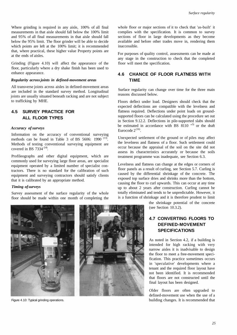
Surface regularity
Where grinding is required in any aisle, 100% of all finalmeasurements in that aisle should fall below the 100% limitand 95% of all final measurements in that aisle should fallbelow the 95% limit. The floor grinder will be able to decidewhich points are left at the 100% limit; it is recommendedthat, where practical, these higher value Property points areat the ends of aisles.
Grinding (Figure 4.10) will affect the appearance of thefloor, particularly where a dry shake finish has been used toenhance appearance.
Regularity across joints in defined-movement areas
All transverse joints across aisles in defined-movement areasare included in the standard survey method. Longitudinaljoints are usually situated beneath racking and are not subjectto trafficking by MHE.
4.5 SURVEY PRACTICE FORALL FLOOR TYPES
Accuracy of surveys
Information on the accuracy of conventional surveyingmethods can be found in Table 3 of BS 5606: 1990 (13).Methods of testing conventional surveying equipment arecovered in BS 7334 (14).
Profileographs and other digital equipment, which arecommonly used for surveying large floor areas, are specialistequipment operated by a limited number of specialist con-tractors. There is no standard for the calibration of suchequipment and surveying contractors should satisfy clientsthat it is calibrated by an appropriate method.
Timing of surveys
Survey assessment of the surface regularity of the wholefloor should be made within one month of completing the
Figure 4.10: Typical grinding operations.
whole floor or major sections of it to check that 'as-built' itcomplies with the specification. It is common to surveysections of floor in large developments as they becomeavailable and before other trades move in, rendering theminaccessible.
For purposes of quality control, assessments can be made atany stage in the construction to check that the completedfloor will meet the specification.
4.6 CHANCE OF FLOOR FLATNESS WITHTIME
Surface regularity can change over time for the three mainreasons discussed below.
Floors deflect under load. Designers should check that theexpected deflections are compatible with the levelness andflatness required. Deflections under point loads on ground-supported floors can be calculated using the procedure set outin Section 9.12.2. Deflections in pile-supported slabs shouldbe estimated in accordance with BS 8110 "5) or the draftEurocode 2 (16).
Unexpected settlement of the ground or of piles may affectthe levelness and flatness of a floor. Such settlement couldoccur because the appraisal of the soil on the site did notassess its characteristics accurately or because the soilstreatment programme was inadequate, see Section 6.3.
Levelness and flatness can change at the edges or corners offloor panels as a result of curling, see Section 5.7. Curling iscaused by the differential shrinkage of the concrete. Theexposed top surface dries and shrinks more than the bottom,causing the floor to curl upwards. This can occur at any timeup to about 2 years after construction. Curling cannot betotally eliminated and tends to be unpredictable. However, itis a function of shrinkage and it is therefore prudent to limit
the shrinkage potential of the concrete(see Section 10.3.2).
4.7 CONVERTING FLOORS TODEFINED-MOVEMENTSPECIFICATIONS
As noted in Section 4.2, if a building isintended for high racking with verynarrow aisles it is inadvisable to designthe floor to meet a free-movement speci-fication. This practice sometimes occursin 'speculative' developments where atenant and the required floor layout havenot been identified. It is recommendedthat floors are not constructed until thefinal layout has been designed.
Older floors are often upgraded todefined-movement use when the use of abuilding changes. It is recommended that
25
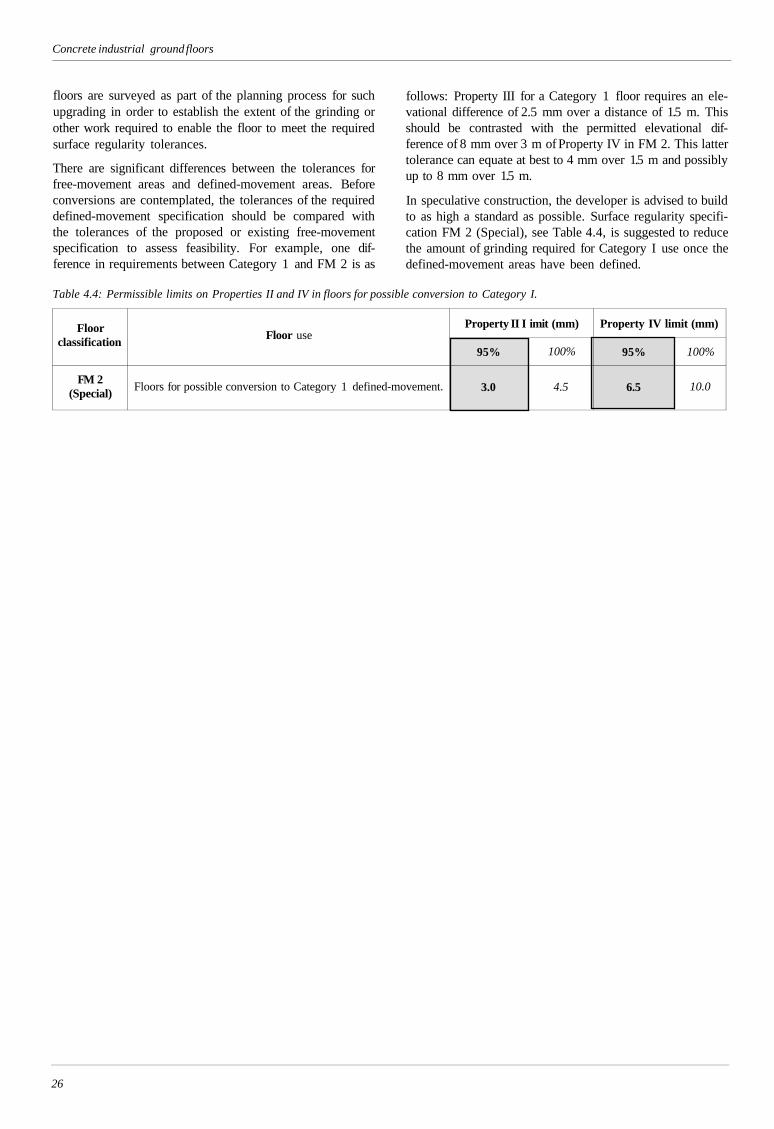
Concrete industrial ground floors
floors are surveyed as part of the planning process for suchupgrading in order to establish the extent of the grinding orother work required to enable the floor to meet the requiredsurface regularity tolerances.
There are significant differences between the tolerances forfree-movement areas and defined-movement areas. Beforeconversions are contemplated, the tolerances of the requireddefined-movement specification should be compared withthe tolerances of the proposed or existing free-movementspecification to assess feasibility. For example, one dif-ference in requirements between Category 1 and FM 2 is as
follows: Property III for a Category 1 floor requires an ele-vational difference of 2.5 mm over a distance of 1.5 m. Thisshould be contrasted with the permitted elevational dif-ference of 8 mm over 3 m of Property IV in FM 2. This lattertolerance can equate at best to 4 mm over 1.5 m and possiblyup to 8 mm over 1.5 m.
In speculative construction, the developer is advised to buildto as high a standard as possible. Surface regularity specifi-cation FM 2 (Special), see Table 4.4, is suggested to reducethe amount of grinding required for Category I use once thedefined-movement areas have been defined.
Table 4.4: Permissible limits on Properties II and IV in floors for possible conversion to Category I.
Floorclassification
FM 2(Special)
Floor use
Floors for possible conversion to Category 1 defined-movement.
Property II I
95%
3.0
imit (mm)
100%
4.5
Property IV limit (mm)
95%
6.5
100%
10.0
26
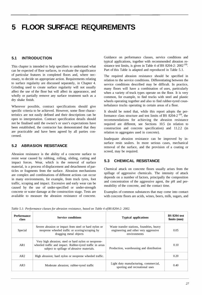
5 FLOOR SURFACE REQUIREMENTS
5.1 INTRODUCTION
This chapter is intended to help specifiers to understand whatcan be expected of floor surfaces, to evaluate the significanceof particular features in completed floors and, where nec-essary, to decide on appropriate action. Requirements relatingto surface regularity are discussed separately, in Chapter 4.Grinding used to create surface regularity will not usuallyaffect the use of the floor but will affect its appearance, andwholly or partially remove any surface treatment such as adry shake finish.
Wherever possible, contract specifications should givespecific criteria to be achieved. However, some floor charac-teristics are not easily defined and their descriptions can beopen to interpretation. Contract specification details shouldnot be finalised until the owner's or user's expectations havebeen established, the contractor has demonstrated that theyare practicable and have been agreed by all parties con-cerned.
5.2 ABRASION RESISTANCE
Abrasion resistance is the ability of a concrete surface toresist wear caused by rubbing, rolling, sliding, cutting andimpact forces. Wear, which is the removal of surfacematerial, is a process of displacement and detachment of par-ticles or fragments from the surface. Abrasion mechanismsare complex and combinations of different actions can occurin many environments, for example, from truck tyres, foottraffic, scraping and impact. Excessive and early wear can becaused by the use of under-specified or under-strengthconcrete or water damage at the construction stage. Tests areavailable to measure the abrasion resistance of concrete.
Guidance on performance classes, service conditions andtypical applications, together with recommended abrasion re-sistance test limits, is given in Table 4 of BS 8204-2: 2002 (10).Part of this Table is adapted and reproduced in Table 5.1.
The required abrasion resistance should be specified inrelation to the service conditions. Differentiating between theservice conditions described may be difficult. In practice,many floors will have a combination of uses, particularlywhen a variety of truck types operate on the floor. It is verycommon, for example, to find trucks with steel and plasticwheels operating together and also to find rubber-tyred coun-terbalance trucks operating in certain areas of a floor.
It should be noted that, while this report adopts the per-formance class structure and test limits of BS 8204-2 (10), therecommendations for achieving the abrasion resistancerequired are different, see Sections 10.5 (in relation toconstruction and concrete specification) and 11.2.2 (inrelation to aggregates used in concrete).
Inadequate abrasion resistance can be improved by in-surface resin sealers. In more serious cases, mechanicalremoval of the surface, and the provision of a coating orscreed, may be required.
5.3 CHEMICAL RESISTANCE
Chemical attack on concrete floors usually arises from thespillage of aggressive chemicals. The intensity of attackdepends on a number of factors, principally the compositionand concentration of the aggressive agent, the pH and per-meability of the concrete, and the contact time.
Examples of common substances that may come into contactwith concrete floors are acids, wines, beers, milk, sugars, and
Table 5.1: Performance classes for abrasion resistance, based on Table 4 of BS 8204-2: 2002.
Performanceclass
Special
AR1
AR2
AR3
Service conditions
Severe abrasion or impact from steel or hard nylon orneoprene wheeled traffic or scoring/scraping by
dragging metal objects
Very high abrasion; steel or hard nylon or neoprene-wheeled traffic and impact. Rubber-tyred traffic in areas
subject to spillage of abrasive materials.
High abrasion; hard nylon or neoprene wheeled traffic.
Moderate abrasion; rubber-tyred traffic
Typical applications
Waste transfer stations, foundries, heavyengineering and other very aggressive
environments
Production, warehousing and distribution
Light duty manufacturing, commercial,sporting and recreational uses
BS 8204 testlimits (mm)
0.05
0.10
0.20
0.40
27
Concrete industrial ground floors
mineral and vegetable oils. Commonly encounteredmaterials that are harmful to concrete are listed in ConcreteSociety Technical Report 54 (l7)and a more comprehensivelisting is given in a Portland Cement Association guide (l8).
Any agent that attacks concrete will eventually cause surfacedamage if it remains in contact with the floor for longenough. Although frequent cleaning to remove aggressiveagents will reduce deterioration, repeated cycles of spillageand cleaning will cause long-term surface damage, seeSection 10.6.
Where chemical attack is likely, consideration should begiven to protecting the floor with a chemically resistantmaterial or system that will resist the action of the aggressiveagent. Advice on resin coatings is available in BS 8204-6 (l9)
and from specialist suppliers and applicators.
5.4 COLOUR AND APPEARANCE
Concrete floors are constructed primarily from naturallyoccurring materials and finished by techniques that cannot becontrolled as precisely as in a factory production process.The final appearance of a floor will never be as uniform as apainted surface finish. However, some features of a concretefloor that are visible in the first few weeks after it has beencast relate to the drying of the floor and become less visiblewith time. More care is needed at finishing stages whenappearance is important, see Section 12.5.
Floors can be constructed with a 'dry shake finish' as a thintopping layer, see Section 11.4. These sometimes includepigments to give colour to the finished surface. However,these do not give the uniformity or intensity of colour of apainted finish and the same appearance considerations applyto these finishes as to ordinary concrete. Floor users are rec-ommended to inspect existing floors in use to evaluate thebenefits of such finishes and the effects that can be achieved.
For bold and consistent colour, it is necessary to use a surfacecoating or paint. On-going maintenance will then be required.
5.5 CRACKING
Cracking occurs when the tensile stress in a section of slabexceeds the tensile strength of the concrete. This situationmost often occurs when the long-term drying shrinkage ofthe slab is restrained for some reason. Such cracks do notgenerally have any structural significance. Less commonlyhowever, cracks can occur because of overloading orstructural inadequacy, and some restraint-induced crackscould have structural implications because of their positionin relation to applied loads. Many factors affect the for-mation of restrained shrinkage cracks and it is difficult to becertain that a floor will be completely crack-free.
Investigation of the cause of cracking is always requiredbefore any treatment; the designer and contractor should payparticular attention to isolation details such as manholes, re-entrant corners or columns that may cause restraint to
shrinkage. Early loading of slabs as part of fast-track pro-grammes can cause pinning of the slab to the sub-base,which may restrain shrinkage and cause cracking.
Concrete Society Technical Report 22, Non-structuralcracks in concrete (20), gives detailed guidance on non-structural cracking, its causes, evaluation and treatment.
Fine cracks may be of concern in terms of appearance, andthey should be monitored as part of the floor inspection andmaintenance regime. If the arrises of a crack begin to spall orthe crack widens, it should be treated to avoid further deteri-oration. However, this should be balanced against a need toleave new cracks untreated until they have become dormanti.e. not opening any further. Where cracks are not dormantand it is considered essential to provide some degree of arrissupport, then semi-flexible sealants should be used. SeeSection 8.12.
If it is suspected that cracking has been caused by somestructural deficiency, a careful reassessment of the designmust be made before any evaluation of remedial action ismade.
5.6 CRAZING
Crazing is common on most power-finished floors. It tendsto be more visible on floors that are wetted and cleaned as theextremely fine cracks trap moisture and dust. Crazing is con-sidered to be a matter of appearance only, and generally nostructural or serviceability issues are associated.
The mechanisms of crazing in floors are not fully understoodbut it is known that the surface zone consists predominantlyof mortar paste. In power-finished floors, this paste is inten-sively compacted by the trowelling process and can have avery low water/cement ratio. As the mechanism is poorlyunderstood it is not possible to recommend measures that canreduce its occurrence.
There is no appropriate treatment for crazing and so if thisfeature is unacceptable to the user, provision should be madeat planning stage for over-painting but this will incur on-going maintenance costs.
5.7 CURLING
The process of curling is explained in Section 4.6.
Curling is quite common but generally has no practical sig-nificance and therefore often needs no action. However, floorpanels sometimes curl to an extent that surface regularity isaffected. Chapter 4 and Appendix C provide detailedguidance on surface regularity. Where necessary, departuresfrom the required surface regularity can be corrected bygrinding.
Curling can cause a loss of sub-base support and slab rockingand should be monitored as part of the maintenance regimeand dealt with as required. Under-slab grouting can restoresupport.
28
Floor surface requirements
5.8 DELAMINATION
Delamination is the process whereby a thin (2-4 mm) layerbecomes detached from the surface and breaks down usuallyunder trafficking (2 I). The mechanisms of delamination arenot fully understood but are believed to result from severalfactors, including differential setting of the surface concrete,air content and bleed characteristics of the concrete. Accel-erated drying of the surface by cross winds from openenvironments can significantly affect bleeding and set char-acteristics.
Delamination is repaired by cutting away the affectedsurface in areas bounded by shallow saw cuts and then fillingwith cement- or resin-based mortar systems. In some cases,where the laminated surface has not been disturbed, it maybe possible to repair small areas by injecting a low viscosityepoxy resin into the interface.
5.9 SLIP RESISTANCE
The slip resistance of a power-finished floor surface dependson four factors: the floor surface, the footwear worn bypeople, the tyres on the materials handling equipment, andthe presence of surface contaminants. In many industrialsituations, contaminants may be the most important factor.The designer should therefore establish at an early stagewhat contaminants are likely to be present during the normaloperation of the premises, as this may dictate the floor finishrequired.
As a rule, clean, dry concrete floors are reasonably slip resistantwith most but not all shoe and tyre materials. However, inpractice concrete floors are not always clean and dry. Threemain types of surface contaminants must be considered:
• Dusts. These are divided into 'soft' and 'hard' dusts. Thesoft type, such as talc, flour and cement dust, form a thinlayer on both the concrete and the shoe sole whichmodifies the frictional performance of the two, poten-tially reducing the slip resistance. The hard type of dust,usually of much larger grain size, can act like ballbearings, particularly if the grains are rounded rather thanangular, again potentially reducing slip resistance.
• Coatings. These often arise from the use of sprays, forexample release agents that are used in factories. Theycan also be polishes, oils or paints; those containing si1-icones are particularly problematical in respect of slipresistance, and they can affect a wide area around wherethey are used. Their action modifies the concrete surfaceand may reduce slip resistance to an unacceptable level.
• Liquids. These form a very thin lubricating film betweenthe shoe sole and the concrete. This occurs most withfree-flowing liquids, and the lower their viscosity themore likely they are to cause a slip, and the rougher thesurface needs to be to overcome the problem. Water is acommon cause of slipping accidents on smooth concretefloors, particularly those that have been well trowelled toproduce abrasion resistance.
To combat the effects of the various surface contaminants adegree of roughness must be provided in the concrete floor.How this is achieved will depend on the type of floor, the wearcharacteristics required, etc. In some instances only a lighttexture is needed, for example, a peak to trough roughness, Rz,of 10 µm (22). However, under continued pedestrian use,surfaces with such low roughness can become polished andlose their original slip resistance.
Because applying a texture almost inevitably affects the wearcharacteristics, an alternative solution is for the user to adoptmore appropriate housekeeping methods in order to reduce oreliminate the contaminant problem or confine it to a definedarea of the floor where special precautions can be taken.
It is sometimes possible to overcome slip problems by the useof special footwear designed to provide high slip resistance indifficult situations. It should be recognised that this does notinclude normal 'safety' footwear, which may not give sig-nificant slip resistance benefit. While most footwear issatisfactory on concrete surfaces that are clean and dry, somematerials have very low values of slip resistance.
In order to confirm the slip resistance of the floor, testsshould be carried out using an appropriate test method. Thependulum described in BS 8204-2(l0) is the only machine thatreplicates liquid contamination and which also gives credibleresults in dry conditions. The procedure for use of thependulum and the criteria for assessing the results are givenin BS 8204-2. The 'Tortus' machine and other 'sled' typeinstruments can be used but only in dry conditions.
The commonly used process of power finishing, whichproduces good abrasion resistance, also tends to create lowerslip resistance. Where slip resistance is of great importance,consideration may be given to further surface treatment. Thiscould be shot blasting, acid etching or the application ofresin-bound aggregate finishes. This latter method is particu-larly useful in areas adjacent to entrances where floors canbecome wetted by rain or water on incoming vehicles.
5.10 SURFACE AGGREGATE
Occasionally, aggregate particles lie exposed at or are veryclose to the surface. If they are well 'locked into' the surface,they are unlikely to affect durability although theirappearance may be considered an issue. However, particlescan be dislodged by materials handling equipment or otheractions, leaving small surface voids. These voids can bedrilled out and filled with resin mortar(23).
Where soft particles, such as naturally occurring mudstone orlignite, are exposed in the surface, they should be removedby drilling and replaced with mortar as described above.
5.11 SURFACE FIBRES
Steel fibres may be exposed at the concrete surface, dependingon the fibre type, concrete mix proportions, mixing and floorfinishing techniques. Their incidence can be significantly re-
29

Concrete industrial ground floors
duced by the use of a dry shake finish. Fibres that affect ser-viceability can be 'snipped off' when the concrete has hardened.
5.12 SURFACE FINISH MARKS
Trowel marks such as 'swirls' or discolouration from bur-nishing are often a consequence of the normal variations in
setting of the concrete or occasionally from poor finishing,such as over-trowelling. Usually the visual impact of thesemarks reduces significantly with time.
Excess curing compound or multiple layers of curingcompound cause darker areas. These wear and disappearwith time and use of the floor without adverse effect on thesurface. See also Section 12.5.
30
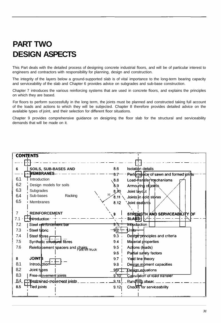
PART TWODESIGN ASPECTSThis Part deals with the detailed process of designing concrete industrial floors, and will be of particular interest toengineers and contractors with responsibility for planning, design and construction.
The integrity of the layers below a ground-supported slab is of vital importance to the long-term bearing capacityand serviceability of the slab and Chapter 6 provides advice on subgrades and sub-base construction.
Chapter 7 introduces the various reinforcing systems that are used in concrete floors, and explains the principleson which they are based.
For floors to perform successfully in the long term, the joints must be planned and constructed taking full accountof the loads and actions to which they will be subjected. Chapter 8 therefore provides detailed advice on theavailable types of joint, and their selection for different floor situations.
Chapter 9 provides comprehensive guidance on designing the floor slab for the structural and serviceabilitydemands that will be made on it.
31
6
6.16.26.36.46.5
SOILS, SUB-BASES AND
Introduction
Design models for soils
SubgradesSub-bases Racking
Membranes
77.17.27.37.47.57.6
8
8.18.28.38.48.5
REINFORCEMENT
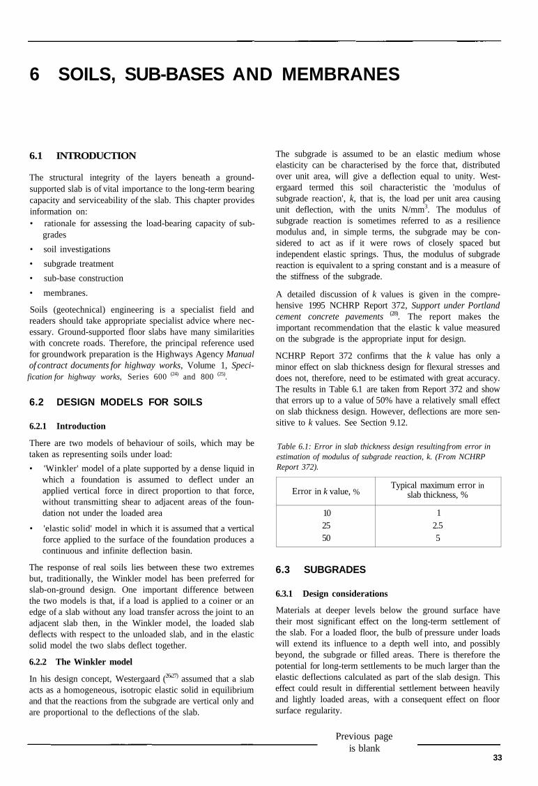
6 SOILS, SUB-BASES AND MEMBRANES
6.1 INTRODUCTION
The structural integrity of the layers beneath a ground-supported slab is of vital importance to the long-term bearingcapacity and serviceability of the slab. This chapter providesinformation on:• rationale for assessing the load-bearing capacity of sub-
grades
• soil investigations
• subgrade treatment
• sub-base construction
• membranes.
Soils (geotechnical) engineering is a specialist field andreaders should take appropriate specialist advice where nec-essary. Ground-supported floor slabs have many similaritieswith concrete roads. Therefore, the principal reference usedfor groundwork preparation is the Highways Agency Manualof contract documents for highway works, Volume 1, Speci-fication for highway works, Series 600 (24) and 800 (25).
6.2 DESIGN MODELS FOR SOILS
6.2.1 Introduction
There are two models of behaviour of soils, which may betaken as representing soils under load:
• 'Winkler' model of a plate supported by a dense liquid inwhich a foundation is assumed to deflect under anapplied vertical force in direct proportion to that force,without transmitting shear to adjacent areas of the foun-dation not under the loaded area
• 'elastic solid' model in which it is assumed that a verticalforce applied to the surface of the foundation produces acontinuous and infinite deflection basin.
The response of real soils lies between these two extremesbut, traditionally, the Winkler model has been preferred forslab-on-ground design. One important difference betweenthe two models is that, if a load is applied to a coiner or anedge of a slab without any load transfer across the joint to anadjacent slab then, in the Winkler model, the loaded slabdeflects with respect to the unloaded slab, and in the elasticsolid model the two slabs deflect together.
6.2.2 The Winkler model
In his design concept, Westergaard (26'27) assumed that a slabacts as a homogeneous, isotropic elastic solid in equilibriumand that the reactions from the subgrade are vertical only andare proportional to the deflections of the slab.
The subgrade is assumed to be an elastic medium whoseelasticity can be characterised by the force that, distributedover unit area, will give a deflection equal to unity. West-ergaard termed this soil characteristic the 'modulus ofsubgrade reaction', k, that is, the load per unit area causingunit deflection, with the units N/mm3. The modulus ofsubgrade reaction is sometimes referred to as a resiliencemodulus and, in simple terms, the subgrade may be con-sidered to act as if it were rows of closely spaced butindependent elastic springs. Thus, the modulus of subgradereaction is equivalent to a spring constant and is a measure ofthe stiffness of the subgrade.
A detailed discussion of k values is given in the compre-hensive 1995 NCHRP Report 372, Support under Portlandcement concrete pavements (28). The report makes theimportant recommendation that the elastic k value measuredon the subgrade is the appropriate input for design.
NCHRP Report 372 confirms that the k value has only aminor effect on slab thickness design for flexural stresses anddoes not, therefore, need to be estimated with great accuracy.The results in Table 6.1 are taken from Report 372 and showthat errors up to a value of 50% have a relatively small effecton slab thickness design. However, deflections are more sen-sitive to k values. See Section 9.12.
Table 6.1: Error in slab thickness design resulting from error inestimation of modulus of subgrade reaction, k. (From NCHRPReport 372).
Error in k value,
102550
%Typical maximum error
slab thickness, %
12.55
in
6.3 SUBGRADES
6.3.1 Design considerations
Materials at deeper levels below the ground surface havetheir most significant effect on the long-term settlement ofthe slab. For a loaded floor, the bulb of pressure under loadswill extend its influence to a depth well into, and possiblybeyond, the subgrade or filled areas. There is therefore thepotential for long-term settlements to be much larger than theelastic deflections calculated as part of the slab design. Thiseffect could result in differential settlement between heavilyand lightly loaded areas, with a consequent effect on floorsurface regularity.
Previous pageis blank
33
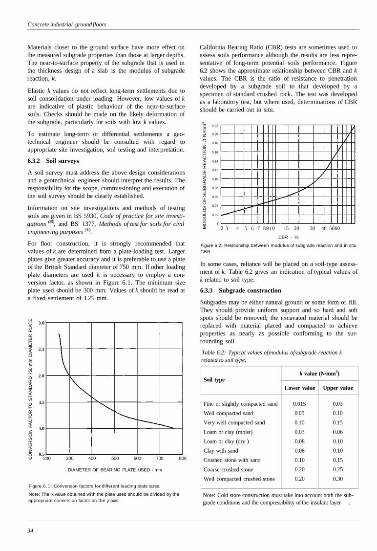
Concrete industrial ground floors
Materials closer to the ground surface have more effect onthe measured subgrade properties than those at larger depths.The near-to-surface property of the subgrade that is used inthe thickness design of a slab is the modulus of subgradereaction, k.
Elastic k values do not reflect long-term settlements due tosoil consolidation under loading. However, low values of kare indicative of plastic behaviour of the near-to-surfacesoils. Checks should be made on the likely deformation ofthe subgrade, particularly for soils with low k values.
To estimate long-term or differential settlements a geo-technical engineer should be consulted with regard toappropriate site investigation, soil testing and interpretation.
6.3.2 Soil surveys
A soil survey must address the above design considerationsand a geotechnical engineer should interpret the results. Theresponsibility for the scope, commissioning and execution ofthe soil survey should be clearly established.
Information on site investigations and methods of testingsoils are given in BS 5930, Code of practice for site investi-gations (29), and BS 1377, Methods of test for soils for civilengineering purposes (30).
For floor construction, it is strongly recommended thatvalues of k are determined from a plate-loading test. Largerplates give greater accuracy and it is preferable to use a plateof the British Standard diameter of 750 mm. If other loadingplate diameters are used it is necessary to employ a con-version factor, as shown in Figure 6.1. The minimum sizeplate used should be 300 mm. Values of k should be read ata fixed settlement of 1.25 mm.
CO
NV
ER
SIO
N F
AC
TOR
TO
ST
AN
DA
RD
750
mm
DIA
ME
TE
R P
LATE
Figure 6.1: Conversion factors for different loading plate sizes.
Note: The k value obtained with the plate used should be divided by theappropriate conversion factor on the y-axis.
California Bearing Ratio (CBR) tests are sometimes used toassess soils performance although the results are less repre-sentative of long-term potential soils performance. Figure6.2 shows the approximate relationship between CBR and kvalues. The CBR is the ratio of resistance to penetrationdeveloped by a subgrade soil to that developed by aspecimen of standard crushed rock. The test was developedas a laboratory test, but where used, determinations of CBRshould be carried out in situ.
MO
DU
LUS
OF
SU
BG
RA
DE
RE
AC
TIO
N,
/t-N
/mm
3
0.22
0.20
0.18
0.16
0.14
0.12
0.10
0.08
0.06
0.04
0.02
02 3 4 5 6 7 8910 15 20 30 40 5060
CBR - %
Figure 6.2: Relationship between modulus of subgrade reaction and in situCBR.
In some cases, reliance will be placed on a soil-type assess-ment of k. Table 6.2 gives an indication of typical values ofk related to soil type.
6.3.3 Subgrade construction
Subgrades may be either natural ground or some form of fill.They should provide uniform support and so hard and softspots should be removed; the excavated material should bereplaced with material placed and compacted to achieveproperties as nearly as possible conforming to the sur-rounding soil.
Table 6.2: Typical values of modulus of subgrade reaction krelated to soil type.
Soil type
Fine or slightly compacted sand
Well compacted sand
Very well compacted sand
Loam or clay (moist)
Loam or clay (dry )
Clay with sand
Crushed stone with sand
Coarse crushed stone
Well compacted crushed stone
k value (N/mm3)
Lower value
0.015
0.05
0.10
0.03
0.08
0.08
0.10
0.20
0.20
Upper value
0.03
0.10
0.15
0.06
0.10
0.10
0.15
0.25
0.30
Note: Cold store construction must take into account both the sub-grade conditions and the compressibility of the insulant layer .
34
3.0
2.5
2.0
1.5
1.0
0.5200 300 400 500 600 700 800
DIAMETER OF BEARING PLATE USED - mm
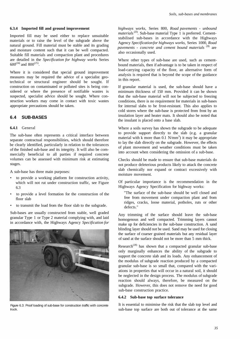
Soils, sub-bases and membranes
6.3.4 Imported fill and ground improvement
Imported fill may be used either to replace unsuitablematerials or to raise the level of the subgrade above thenatural ground. Fill material must be stable and its gradingand moisture content such that it can be well compacted.Suitable fill materials and compaction plant and proceduresare detailed in the Specification for highway works Series600(24) and 800(25).
Where it is considered that special ground improvementmeasures may be required the advice of a specialist geo-technical or structural engineer should be sought. Ifconstruction on contaminated or polluted sites is being con-sidered or where the presence of notifiable wastes issuspected, specialist advice should be sought. Where con-struction workers may come in contact with toxic wastesappropriate precautions should be taken.
6.4 SUB-BASES
6.4.1 General
The sub-base often represents a critical interface betweenseparate contractual responsibilities, which should thereforebe clearly identified, particularly in relation to the tolerancesof the finished sub-base and its integrity. It will also be com-mercially beneficial to all parties if required concretevolumes can be assessed with minimum risk at estimatingstages.
A sub-base has three main purposes:
• to provide a working platform for construction activity,which will not rut under construction traffic, see Figure6.3
• to provide a level formation for the construction of thefloor slab
• to transmit the load from the floor slab to the subgrade.
Sub-bases are usually constructed from stable, well gradedgranular Type 1 or Type 2 material complying with, and laidin accordance with, the Highways Agency Specification for
Figure 6.3: Proof loading of sub-base for construction traffic with concretetruck.
highways works, Series 800, Road pavements - unboundmaterials (25). Sub-base material Type 1 is preferred. Cement-stabilised sub-bases in accordance with the HighwaysAgency Specification for highways works, Series 1000, Roadpavements - concrete and cement bound materials (3I) arealso occasionally used.
Where other types of sub-base are used, such as cement-bound materials, then if advantage is to be taken in respect ofload-carrying capacity of the floor, an alternative form ofanalysis is required that is beyond the scope of the guidancein this report.
If granular material is used, the sub-base should have aminimum thickness of 150 mm. Provided it can be shownthat the sub-base material will not be subjected to freezingconditions, there is no requirement for materials in sub-basesfor internal slabs to be frost-resistant. This also applies tocold stores where the sub-base is protected from frost by aninsulation layer and heater mats. It should also be noted thatthe insulant is placed onto a base slab.
Where a soils survey has shown the subgrade to be adequateto provide support directly to the slab (e.g. a granularmaterial with k more than 0.1 N/mm3) it may be appropriateto lay the slab directly on the subgrade. However, the effectsof plant movement and weather conditions must be takeninto account when considering the omission of a sub-base.
Checks should be made to ensure that sub-base materials donot produce deleterious products likely to attack the concreteslab chemically nor expand or contract excessively withmoisture movement.
Of particular importance is the recommendation in theHighways Agency Specification for highway works:
"The surface of the sub-base should be well closed andfree from movement under compaction plant and fromridges, cracks, loose material, potholes, ruts or otherdefects."
Any trimming of the surface should leave the sub-basehomogenous and well compacted. Trimming layers cannotmake up for deficiencies in the sub-base construction. A sandblinding layer should not be used. Sand may be used for closingthe surface of coarser grained materials but any residual layerof sand at the surface should not be more than 5 mm thick.
Research(28) has shown that a compacted granular sub-baseonly marginally enhances the ability of the subgrade tosupport the concrete slab and its loads. Any enhancement ofthe modulus of subgrade reaction produced by a compactedgranular sub-base is so small that, compared with the vari-ations in properties that will occur in a natural soil, it shouldbe neglected in the design process. The modulus of subgradereaction should always, therefore, be measured on thesubgrade. However, this does not remove the need for goodsub-base construction practice.
6.4.2 Sub-base top surface tolerance
It is essential to minimise the risk that the slab top level andsub-base top surface are both out of tolerance at the same
35
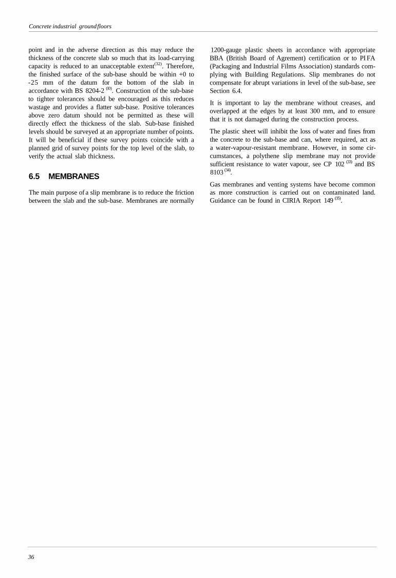
Concrete industrial ground floors
point and in the adverse direction as this may reduce thethickness of the concrete slab so much that its load-carryingcapacity is reduced to an unacceptable extent(32). Therefore,the finished surface of the sub-base should be within +0 to-25 mm of the datum for the bottom of the slab inaccordance with BS 8204-2 (l0). Construction of the sub-baseto tighter tolerances should be encouraged as this reduceswastage and provides a flatter sub-base. Positive tolerancesabove zero datum should not be permitted as these willdirectly effect the thickness of the slab. Sub-base finishedlevels should be surveyed at an appropriate number of points.It will be beneficial if these survey points coincide with aplanned grid of survey points for the top level of the slab, toverify the actual slab thickness.
6.5 MEMBRANES
The main purpose of a slip membrane is to reduce the frictionbetween the slab and the sub-base. Membranes are normally
1200-gauge plastic sheets in accordance with appropriateBBA (British Board of Agrement) certification or to PI FA(Packaging and Industrial Films Association) standards com-plying with Building Regulations. Slip membranes do notcompensate for abrupt variations in level of the sub-base, seeSection 6.4.
It is important to lay the membrane without creases, andoverlapped at the edges by at least 300 mm, and to ensurethat it is not damaged during the construction process.
The plastic sheet will inhibit the loss of water and fines fromthe concrete to the sub-base and can, where required, act asa water-vapour-resistant membrane. However, in some cir-cumstances, a polythene slip membrane may not providesufficient resistance to water vapour, see CP 102 (33) and BS8103 (34).
Gas membranes and venting systems have become commonas more construction is carried out on contaminated land.Guidance can be found in CIRIA Report 149 (35).
36

7 REINFORCEMENT
7.1 INTRODUCTION
This Chapter describes the types and purpose of rein-forcement commonly used in floors:
• steel reinforcement bar
• steel fabric
• steel fibres
• structural synthetic fibres.
Reinforcement spacers and chairs are also mentioned.
7.2 STEEL REINFORCEMENT BAR
Steel reinforcement bar is not commonly used in ground-supported floors although welded steel fabric is, see Section7.3. Where bars are used, for example, to increase localisedload capacity or in some pile-supported slabs (see AppendixD), structural design, and reinforcement placing and fixingshould be in accordance with BS 8110 (l5) or the draftEurocode 2 (16).
Bar reinforcement should meet the requirements of BS4449 M (due to be replaced by BS EN 10080 (37)). Bars aredelivered to site in stock lengths of 12 m, in scheduledlengths or cut and bent to the above standards. Bars shouldbe bent on site only with bending equipment suitable to givethe shapes required by BS 8666 (38). Re-bending of bars aftercasting of concrete is permissible with mild steel bars witha yield strength not greater than 250 N/mm2, and providedthe radius of the bend is not less than that specified in BS8666.
Reinforcing steel should be obtained from a supplier regis-tered under an accredited quality assurance scheme, such asthat operated by CARES, the UK Certification Authority forReinforcing Steels.
If wire-guided vehicles are to operate on the floor, rein-forcement must be fixed deep enough to avoid interferencewith control signals, typically 75 mm for bars of 16 mmdiameter or more.
7.3 STEEL FABRIC
Steel fabric (commonly though incorrectly referred to as'mesh') should be to BS 4483(39). 'A' type fabrics are mostcommonly used in floors. Fabric should be obtained from asupplier registered under an accredited quality assurancescheme such as that operated by CARES, the UK Certifi-cation Authority for Reinforcing Steels. Fabric should befree of loose rust, scale, grease and dirt.
Steel fabric is commonly used in ground-supported floors -the proportion being typically in the order of 0.1 to 0.125%.Traditionally, steel fabric was included with the intention ofcontrolling shrinkage-induced cracking. However, at theselow percentages, there is insufficient steel to affect the crackwidth and crack distribution significantly. Percentages in theorder of 0.4% would be required to achieve the degree ofcontrol typically considered in structural codes of practice,i.e. limiting surface crack widths to about 0.3 mm. Tradi-tionally it was also considered that, for shrinkage crackcontrol, the fabric should be placed in the top of the slab.There are conflicting views on the most effective position forthe fabric but the area of fabric used in a slab is very smalland so its location is generally not critical. In small areaswhere restraint, aspect ratio or other factors are less thanideal, such as around dock levellers (see Figure 7.1), a toplayer of fabric is often used in addition to that in the bottom.
During the 1990s, floor laying became increasingly mech-anised: floors were laid in large areas and sawn into panelsof about 6 x 6 m. Thermal contraction and drying shrinkageare accommodated by the cracks induced below these sawcuts. The fabric limits the opening of these induced cracks toa typical width at the top surface of 1 to 2 mm although somejoints can open wider. These wider openings, known as'dominant joints', are discussed in Section 8.10.2. If mid-panel cracks occur because of shrinkage, the fabric willprovide some restraint to opening of the crack, the width atthe top surface again being 1 to 2 mm.
Empirical evidence suggests that using nominal areas offabric in large area floor construction gives satisfactory
Figure 7.1: Dock levellers. Additional reinforcement may be needed in theareas around each entrance.
37
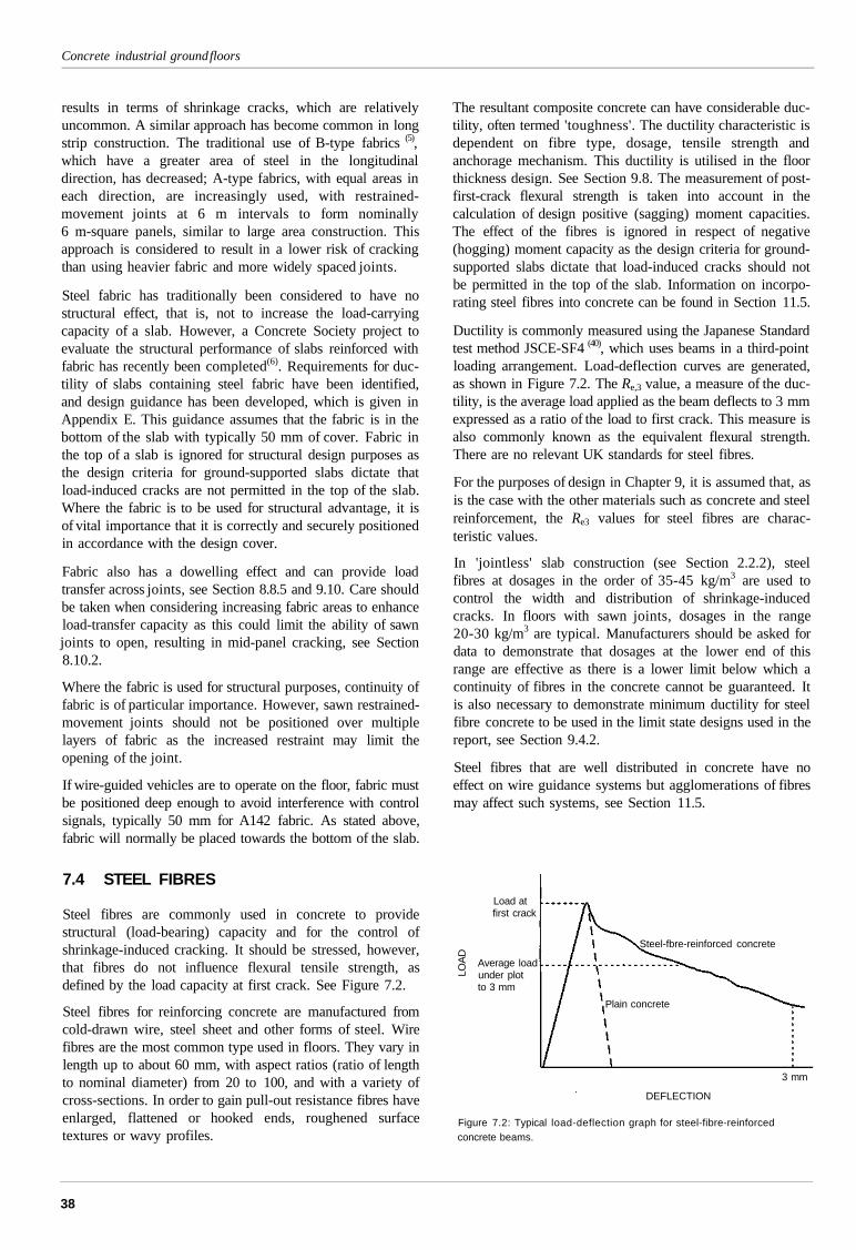
Concrete industrial ground floors
results in terms of shrinkage cracks, which are relativelyuncommon. A similar approach has become common in longstrip construction. The traditional use of B-type fabrics (5),which have a greater area of steel in the longitudinaldirection, has decreased; A-type fabrics, with equal areas ineach direction, are increasingly used, with restrained-movement joints at 6 m intervals to form nominally6 m-square panels, similar to large area construction. Thisapproach is considered to result in a lower risk of crackingthan using heavier fabric and more widely spaced joints.
Steel fabric has traditionally been considered to have nostructural effect, that is, not to increase the load-carryingcapacity of a slab. However, a Concrete Society project toevaluate the structural performance of slabs reinforced withfabric has recently been completed(6). Requirements for duc-tility of slabs containing steel fabric have been identified,and design guidance has been developed, which is given inAppendix E. This guidance assumes that the fabric is in thebottom of the slab with typically 50 mm of cover. Fabric inthe top of a slab is ignored for structural design purposes asthe design criteria for ground-supported slabs dictate thatload-induced cracks are not permitted in the top of the slab.Where the fabric is to be used for structural advantage, it isof vital importance that it is correctly and securely positionedin accordance with the design cover.
Fabric also has a dowelling effect and can provide loadtransfer across joints, see Section 8.8.5 and 9.10. Care shouldbe taken when considering increasing fabric areas to enhanceload-transfer capacity as this could limit the ability of sawnjoints to open, resulting in mid-panel cracking, see Section8.10.2.
Where the fabric is used for structural purposes, continuity offabric is of particular importance. However, sawn restrained-movement joints should not be positioned over multiplelayers of fabric as the increased restraint may limit theopening of the joint.
If wire-guided vehicles are to operate on the floor, fabric mustbe positioned deep enough to avoid interference with controlsignals, typically 50 mm for A142 fabric. As stated above,fabric will normally be placed towards the bottom of the slab.
7.4 STEEL FIBRES
Steel fibres are commonly used in concrete to providestructural (load-bearing) capacity and for the control ofshrinkage-induced cracking. It should be stressed, however,that fibres do not influence flexural tensile strength, asdefined by the load capacity at first crack. See Figure 7.2.
Steel fibres for reinforcing concrete are manufactured fromcold-drawn wire, steel sheet and other forms of steel. Wirefibres are the most common type used in floors. They vary inlength up to about 60 mm, with aspect ratios (ratio of lengthto nominal diameter) from 20 to 100, and with a variety ofcross-sections. In order to gain pull-out resistance fibres haveenlarged, flattened or hooked ends, roughened surfacetextures or wavy profiles.
The resultant composite concrete can have considerable duc-tility, often termed 'toughness'. The ductility characteristic isdependent on fibre type, dosage, tensile strength andanchorage mechanism. This ductility is utilised in the floorthickness design. See Section 9.8. The measurement of post-first-crack flexural strength is taken into account in thecalculation of design positive (sagging) moment capacities.The effect of the fibres is ignored in respect of negative(hogging) moment capacity as the design criteria for ground-supported slabs dictate that load-induced cracks should notbe permitted in the top of the slab. Information on incorpo-rating steel fibres into concrete can be found in Section 11.5.
Ductility is commonly measured using the Japanese Standardtest method JSCE-SF4 (40), which uses beams in a third-pointloading arrangement. Load-deflection curves are generated,as shown in Figure 7.2. The Re,3 value, a measure of the duc-tility, is the average load applied as the beam deflects to 3 mmexpressed as a ratio of the load to first crack. This measure isalso commonly known as the equivalent flexural strength.There are no relevant UK standards for steel fibres.
For the purposes of design in Chapter 9, it is assumed that, asis the case with the other materials such as concrete and steelreinforcement, the Re3 values for steel fibres are charac-teristic values.
In 'jointless' slab construction (see Section 2.2.2), steelfibres at dosages in the order of 35-45 kg/m3 are used tocontrol the width and distribution of shrinkage-inducedcracks. In floors with sawn joints, dosages in the range20-30 kg/m3 are typical. Manufacturers should be asked fordata to demonstrate that dosages at the lower end of thisrange are effective as there is a lower limit below which acontinuity of fibres in the concrete cannot be guaranteed. Itis also necessary to demonstrate minimum ductility for steelfibre concrete to be used in the limit state designs used in thereport, see Section 9.4.2.
Steel fibres that are well distributed in concrete have noeffect on wire guidance systems but agglomerations of fibresmay affect such systems, see Section 11.5.
Load atfirst crack
LOA
D
Average loadunder plotto 3 mm
Steel-fbre-reinforced concrete
Plain concrete
3 mm
DEFLECTION
Figure 7.2: Typical load-deflection graph for steel-fibre-reinforcedconcrete beams.
38
Reinforcement
7.5 STRUCTURAL SYNTHETIC FIBRES
It is necessary to distinguish between the short polypropylene'micro' fibres and the larger synthetic fibres being developedfor structural benefits similar to steel fibres.
Polypropylene micro fibres used at typical dosages of 0.9kg/m3 do not provide any significant post-first-crack duc-tility, as defined and measured by Japanese Standard testmethod JSCE-SF4 (40). Therefore they do not fulfil anystructural role, as would steel fibres with proven structuralperformance.
Structural synthetic fibres are larger and used at significantlyhigher dosages than polypropylene microfibres. (See Section11.6.) As with steel fibres, data should be available to
demonstrate the performance of synthetic structural fibres inpractice (see Section 9.4.3).
7.6 REINFORCEMENT SPACERS ANDCHAIRS
It is important that reinforcement is securely located in theposition required by the designer or its effectiveness may beseverely reduced. Chairs for supporting reinforcement aremanufactured from concrete, plastic or steel. Chairs suitablefor ground-supported slabs are designed to prevent punc-turing of the membrane or sinking into the sub-base. Spacersand chairs and their use should be in accordance with BS7973-1 and BS 7973-2 (4I).
39
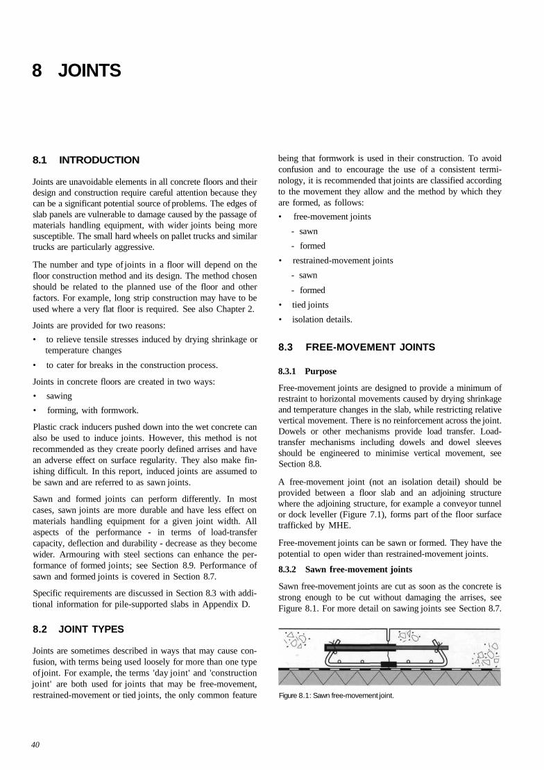
8 JOINTS
8.1 INTRODUCTION
Joints are unavoidable elements in all concrete floors and theirdesign and construction require careful attention because theycan be a significant potential source of problems. The edges ofslab panels are vulnerable to damage caused by the passage ofmaterials handling equipment, with wider joints being moresusceptible. The small hard wheels on pallet trucks and similartrucks are particularly aggressive.
The number and type of joints in a floor will depend on thefloor construction method and its design. The method chosenshould be related to the planned use of the floor and otherfactors. For example, long strip construction may have to beused where a very flat floor is required. See also Chapter 2.
Joints are provided for two reasons:
• to relieve tensile stresses induced by drying shrinkage ortemperature changes
• to cater for breaks in the construction process.
Joints in concrete floors are created in two ways:
• sawing
• forming, with formwork.
Plastic crack inducers pushed down into the wet concrete canalso be used to induce joints. However, this method is notrecommended as they create poorly defined arrises and havean adverse effect on surface regularity. They also make fin-ishing difficult. In this report, induced joints are assumed tobe sawn and are referred to as sawn joints.
Sawn and formed joints can perform differently. In mostcases, sawn joints are more durable and have less effect onmaterials handling equipment for a given joint width. Allaspects of the performance - in terms of load-transfercapacity, deflection and durability - decrease as they becomewider. Armouring with steel sections can enhance the per-formance of formed joints; see Section 8.9. Performance ofsawn and formed joints is covered in Section 8.7.
Specific requirements are discussed in Section 8.3 with addi-tional information for pile-supported slabs in Appendix D.
8.2 JOINT TYPES
Joints are sometimes described in ways that may cause con-fusion, with terms being used loosely for more than one typeof joint. For example, the terms 'day joint' and 'constructionjoint' are both used for joints that may be free-movement,restrained-movement or tied joints, the only common feature
being that formwork is used in their construction. To avoidconfusion and to encourage the use of a consistent termi-nology, it is recommended that joints are classified accordingto the movement they allow and the method by which theyare formed, as follows:
• free-movement joints
- sawn
- formed
• restrained-movement joints
- sawn
- formed
• tied joints
• isolation details.
8.3 FREE-MOVEMENT JOINTS
8.3.1 Purpose
Free-movement joints are designed to provide a minimum ofrestraint to horizontal movements caused by drying shrinkageand temperature changes in the slab, while restricting relativevertical movement. There is no reinforcement across the joint.Dowels or other mechanisms provide load transfer. Load-transfer mechanisms including dowels and dowel sleevesshould be engineered to minimise vertical movement, seeSection 8.8.
A free-movement joint (not an isolation detail) should beprovided between a floor slab and an adjoining structurewhere the adjoining structure, for example a conveyor tunnelor dock leveller (Figure 7.1), forms part of the floor surfacetrafficked by MHE.
Free-movement joints can be sawn or formed. They have thepotential to open wider than restrained-movement joints.
8.3.2 Sawn free-movement joints
Sawn free-movement joints are cut as soon as the concrete isstrong enough to be cut without damaging the arrises, seeFigure 8.1. For more detail on sawing joints see Section 8.7.
Figure 8.1: Sawn free-movement joint.
40
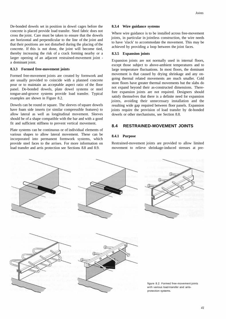
Joints
De-bonded dowels set in position in dowel cages before theconcrete is placed provide load transfer. Steel fabric does notcross the joint. Care must be taken to ensure that the dowelsare horizontal and perpendicular to the line of the joint andthat their positions are not disturbed during the placing of theconcrete. If this is not done, the joint will become tied,thereby increasing the risk of a crack forming nearby or alarger opening of an adjacent restrained-movement joint -a dominant joint.
8.3.3 Formed free-movement joints
Formed free-movement joints are created by formwork andare usually provided to coincide with a planned concretepour or to maintain an acceptable aspect ratio of the floorpanel. De-bonded dowels, plate dowel systems or steeltongue-and-groove systems provide load transfer. Typicalexamples are shown in Figure 8.2.
Dowels can be round or square. The sleeves of square dowelshave foam side inserts (or similar compressible features) toallow lateral as well as longitudinal movement. Sleevesshould be of a shape compatible with the bar and with a goodfit and sufficient stiffness to prevent vertical movement.
Plate systems can be continuous or of individual elements ofvarious shapes to allow lateral movement. These can beincorporated into permanent formwork systems, whichprovide steel faces to the arrises. For more information onload transfer and arris protection see Sections 8.8 and 8.9.
8.3.4 Wire guidance systems
Where wire guidance is to be installed across free-movementjoints, in particular in jointless construction, the wire needsto have 'slack' to accommodate the movement. This may beachieved by providing a loop between the joint faces.
8.3.5 Expansion joints
Expansion joints are not normally used in internal floors,except those subject to above-ambient temperatures and tolarge temperature fluctuations. In most floors, the dominantmovement is that caused by drying shrinkage and any on-going thermal related movements are much smaller. Coldstore floors have greater thermal movements but the slabs donot expand beyond their as-constructed dimensions. There-fore expansion joints are not required. Designers shouldsatisfy themselves that there is a definite need for expansionjoints, avoiding their unnecessary installation and theresulting wide gap required between floor panels. Expansionjoints require the provision of load transfer by de-bondeddowels or other mechanisms, see Section 8.8.
8.4 RESTRAINED-MOVEMENT JOINTS
8.4.1 Purpose
Restrained-movement joints are provided to allow limitedmovement to relieve shrinkage-induced stresses at pre-
figure 8.2: Formed free-movement jointswith various load-transfer and arris-protection systems.
41
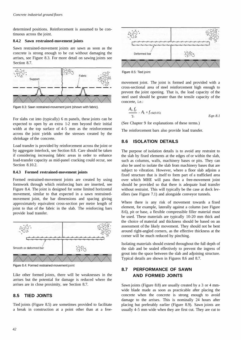
Concrete industrial ground floors
determined positions. Reinforcement is assumed to be con-tinuous across the joint.
8.4.2 Sawn restrained-movement joints
Sawn restrained-movement joints are sawn as soon as theconcrete is strong enough to be cut without damaging thearrises, see Figure 8.3. For more detail on sawing joints seeSection 8.7.
Figure 8.3: Sawn restrained-movement joint (shown with fabric).
For slabs cut into (typically) 6 m panels, these joints can beexpected to open by an extra 1-2 mm beyond their initialwidth at the top surface of 4-5 mm as the reinforcementacross the joint yields under the stresses created by theshrinkage of the concrete.
Load transfer is provided by reinforcement across the joint orby aggregate interlock, see Section 8.8. Care should be takenif considering increasing fabric areas in order to enhanceload-transfer capacity as mid-panel cracking could occur, seeSection 8.10.2.
8.4.3 Formed restrained-movement joints
Formed restrained-movement joints are created by usingformwork through which reinforcing bars are inserted, seeFigure 8.4. The joint is designed for some limited horizontalmovement, similar to that expected in a sawn restrained-movement joint, the bar dimensions and spacing givingapproximately equivalent cross-section per metre length ofjoint to that of the fabric in the slab. The reinforcing barsprovide load transfer.
Figure 8.4: Formed restrained-movement joint
Like other formed joints, there will be weaknesses in thearrises but the potential for damage is reduced where thearrises are in close proximity, see Section 8.7.
8.5 TIED JOINTS
Tied joints (Figure 8.5) are sometimes provided to facilitatea break in construction at a point other than at a free-
Figure 8.5: Tied joint
movement joint. The joint is formed and provided with across-sectional area of steel reinforcement high enough toprevent the joint opening. That is, the load capacity of thesteel used should be greater than the tensile capacity of theconcrete, i.e.:
As fy
Eqn 8.1
(See Chapter 9 for explanations of these terms.)
The reinforcement bars also provide load transfer.
8.6 ISOLATION DETAILS
The purpose of isolation details is to avoid any restraint tothe slab by fixed elements at the edges of or within the slab,such as columns, walls, machinery bases or pits. They canalso be used to isolate the slab from machinery bases that aresubject to vibration. However, where a floor slab adjoins afixed structure that is itself to form part of a trafficked areaover which MHE will pass then a free-movement jointshould be provided so that there is adequate load transferwithout restraint. This will typically be the case at dock lev-ellers (see Figure 7.1) and alongside conveyor tunnels.
Where there is any risk of movement towards a fixedelement, for example, laterally against a column (see Figure8.6), pit or base, a flexible compressible filler material mustbe used. These materials are typically 10-20 mm thick andthe choice of material and thickness should be based on anassessment of the likely movement. They should not be bentaround right-angled corners, as the effective thickness at thecorner will be much reduced by pinching.
Isolating materials should extend throughout the full depth ofthe slab and be sealed effectively to prevent the ingress ofgrout into the space between the slab and adjoining structure.Typical details are shown in Figures 8.6 and 8.7.
8.7 PERFORMANCE OF SAWNAND FORMED JOINTS
Sawn joints (Figure 8.8) are usually created by a 3 or 4 mm-wide blade made as soon as practicable after placing theconcrete when the concrete is strong enough to avoiddamage to the arrises. This is nominally 24 hours afterplacing but preferably earlier (Figure 8.9). Sawn joints areusually 4-5 mm wide when they are first cut. They are cut to
42
γ s
Deformed bar
FabricSupport
> Ac x f ctk(0.05)
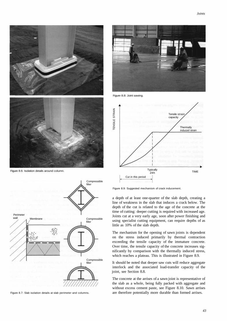
Joints
Figure 8.6: Isolation details around column.
Compressiblefiller
Compressiblefiller
Compressiblefiller
Figure 8.8: Joint sawing.
TE
NS
ILE
ST
RA
INTensile strain,capacity
Thermallyinduced strain
Typically24 h TIME
Cut in this period
Figure 8.7: Slab isolation details at slab perimeter and columns.
Figure 8.9: Suggested mechanism of crack inducement.
a depth of at least one-quarter of the slab depth, creating aline of weakness in the slab that induces a crack below. Thedepth of the cut is related to the age of the concrete at thetime of cutting: deeper cutting is required with increased age.Joints cut at a very early age, soon after power finishing andusing specialist cutting equipment, can require depths of aslittle as 10% of the slab depth.
The mechanism for the opening of sawn joints is dependenton the stress induced primarily by thermal contractionexceeding the tensile capacity of the immature concrete.Over time, the tensile capacity of the concrete increases sig-nificantly by comparison with the thermally induced stress,which reaches a plateau. This is illustrated in Figure 8.9.
It should be noted that deeper saw cuts will reduce aggregateinterlock and the associated load-transfer capacity of thejoint, see Section 8.8.
The concrete at the arrises of a sawn joint is representative ofthe slab as a whole, being fully packed with aggregate andwithout excess cement paste, see Figure 8.10. Sawn arrisesare therefore potentially more durable than formed arrises.
43
Membrane
Perimeterwall
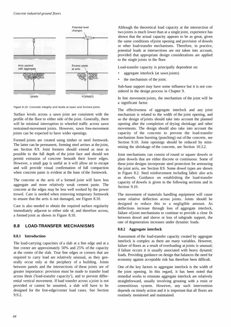
Concrete industrial ground floors
Potential levelchanges
Arris packedwith aggregate
SAWN FORMED
Figure 8.10: Concrete integrity and levels at sawn and formed joints.
Surface levels across a sawn joint are consistent with theprofile of the floor to either side of the joint. Generally, therewill be minimal interruption to wheeled traffic across sawnrestrained-movement joints. However, sawn free-movementjoints can be expected to have wider openings.
Formed joints are created using timber or steel formwork.The latter can be permanent, forming steel arrises at the joint,see Section 8.9. Joint formers should extend as near aspossible to the full depth of the joint face and should notpermit extrusion of concrete beneath their lower edges.However, a small gap is useful as it will allow air to escapeand will provide visual confirmation of full compactionwhen concrete paste is evident at the base of the formwork.
The concrete at the arris of a formed joint will have lessaggregate and more relatively weak cement paste. Theconcrete at the edges may be less well worked by the powertrowel. Care is needed when removing temporary formworkto ensure that the arris is not damaged, see Figure 8.10.
Care is also needed to obtain the required surface regularityimmediately adjacent to either side of, and therefore across,a formed joint as shown in Figure 8.10.
8.8 LOAD-TRANSFER MECHANISMS
8.8.1 Introduction
The load-carrying capacities of a slab at a free edge and at afree corner are approximately 50% and 25% of the capacityat the centre of the slab. True free edges or corners that arerequired to carry load are relatively unusual, as they gen-erally occur only at the periphery of a building. Jointsbetween panels and the intersections of these joints are ofgreater importance: provision must be made to transfer loadacross them ('load-transfer capacity'), and to prevent differ-ential vertical movement. If load transfer across a joint is notprovided or cannot be assumed, a slab will have to bedesigned for the free-edge/corner load cases. See Section9.9.2.
Although the theoretical load capacity at the intersection oftwo joints is much lower than at a single joint, experience hasshown that the actual capacity appears to be as great, giventhe same conditions of joint opening and provision of dowelsor other load-transfer mechanisms. Therefore, in practice,potential loads at intersections are not taken into account,provided that appropriate design considerations are appliedto the single joints in the floor.
Load-transfer capacity is principally dependent on:
• aggregate interlock (at sawn joints)
• the mechanism of the joint.
Sub-base support may have some influence but it is not con-sidered in the design process in Chapter 9.
In free movement joints, the mechanism of the joint will bea significant factor.
The effectiveness of aggregate interlock and any jointmechanism is related to the width of the joint opening, andso the design of joints should take into account the plannedopening after the completion of drying shrinkage and othermovements. The design should also take into account thecapacity of the concrete to prevent the load-transfermechanism from bursting (punching) out of the concrete, seeSection 9.10. Joint openings should be reduced by mini-mising the shrinkage of the concrete, see Section 10.3.2.
Joint mechanisms can consist of round or square dowels orplate dowels that are either discrete or continuous. Some ofthese joint designs incorporate steel protection for armouringthe joint arris, see Section 8.9. Some dowel types are shownin Figure 8.2. Steel reinforcement including fabric also actsas dowels. Guidance on establishing the load-transfercapacity of dowels is given in the following sections and inSection 9.10.
The movement of materials handling equipment will causesome relative deflection across joints. Joints should bedesigned to reduce this to a negligible amount. Asdeflections increase through loss of aggregate interlock,failure of joint mechanisms to continue to provide a close fitbetween dowel and sleeve or loss of subgrade support, therate of degeneration increases under dynamic loads.
8.8.2 Aggregate interlock
Assessment of the load-transfer capacity created by aggregateinterlock is complex as there are many variables. However,failure of floors as a result of overloading at joints is unusual;if failure occurs it is usually associated with heavy dynamicloads. Providing guidance on design that balances the need foreconomy against acceptable risk has therefore been difficult.
One of the key factors in aggregate interlock is the width ofthe joint opening. In this regard, it has been noted thatremedial works to reinstate aggregate interlock are relativelystraightforward, usually involving grouting with a resin orcementitious system. However, any such interventiondepends on timely action and it is important that all floors areroutinely monitored and maintained.
44
Excess pasteat arris
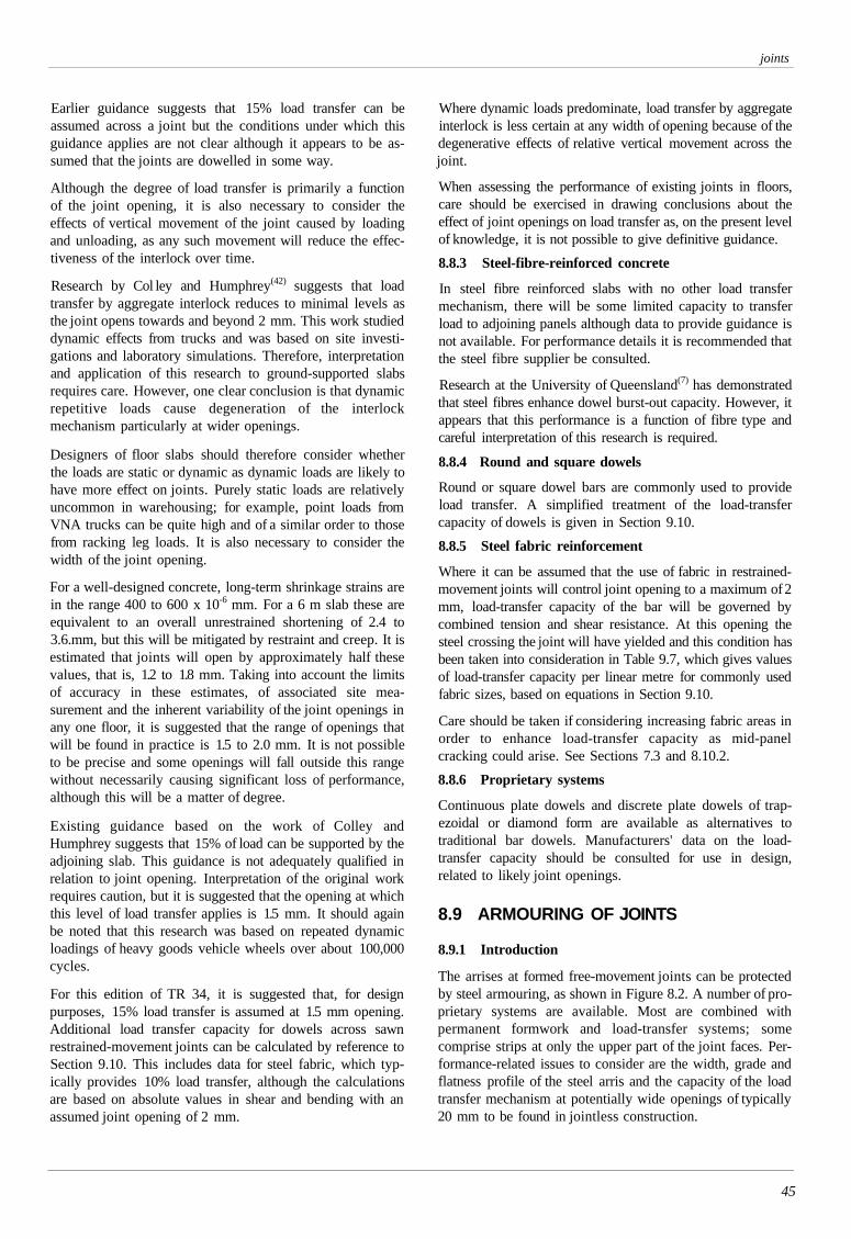
joints
Earlier guidance suggests that 15% load transfer can beassumed across a joint but the conditions under which thisguidance applies are not clear although it appears to be as-sumed that the joints are dowelled in some way.
Although the degree of load transfer is primarily a functionof the joint opening, it is also necessary to consider theeffects of vertical movement of the joint caused by loadingand unloading, as any such movement will reduce the effec-tiveness of the interlock over time.
Research by Col ley and Humphrey(42) suggests that loadtransfer by aggregate interlock reduces to minimal levels asthe joint opens towards and beyond 2 mm. This work studieddynamic effects from trucks and was based on site investi-gations and laboratory simulations. Therefore, interpretationand application of this research to ground-supported slabsrequires care. However, one clear conclusion is that dynamicrepetitive loads cause degeneration of the interlockmechanism particularly at wider openings.
Designers of floor slabs should therefore consider whetherthe loads are static or dynamic as dynamic loads are likely tohave more effect on joints. Purely static loads are relativelyuncommon in warehousing; for example, point loads fromVNA trucks can be quite high and of a similar order to thosefrom racking leg loads. It is also necessary to consider thewidth of the joint opening.
For a well-designed concrete, long-term shrinkage strains arein the range 400 to 600 x 10-6 mm. For a 6 m slab these areequivalent to an overall unrestrained shortening of 2.4 to3.6.mm, but this will be mitigated by restraint and creep. It isestimated that joints will open by approximately half thesevalues, that is, 1.2 to 1.8 mm. Taking into account the limitsof accuracy in these estimates, of associated site mea-surement and the inherent variability of the joint openings inany one floor, it is suggested that the range of openings thatwill be found in practice is 1.5 to 2.0 mm. It is not possibleto be precise and some openings will fall outside this rangewithout necessarily causing significant loss of performance,although this will be a matter of degree.
Existing guidance based on the work of Colley andHumphrey suggests that 15% of load can be supported by theadjoining slab. This guidance is not adequately qualified inrelation to joint opening. Interpretation of the original workrequires caution, but it is suggested that the opening at whichthis level of load transfer applies is 1.5 mm. It should againbe noted that this research was based on repeated dynamicloadings of heavy goods vehicle wheels over about 100,000cycles.
For this edition of TR 34, it is suggested that, for designpurposes, 15% load transfer is assumed at 1.5 mm opening.Additional load transfer capacity for dowels across sawnrestrained-movement joints can be calculated by reference toSection 9.10. This includes data for steel fabric, which typ-ically provides 10% load transfer, although the calculationsare based on absolute values in shear and bending with anassumed joint opening of 2 mm.
Where dynamic loads predominate, load transfer by aggregateinterlock is less certain at any width of opening because of thedegenerative effects of relative vertical movement across thejoint.
When assessing the performance of existing joints in floors,care should be exercised in drawing conclusions about theeffect of joint openings on load transfer as, on the present levelof knowledge, it is not possible to give definitive guidance.
8.8.3 Steel-fibre-reinforced concrete
In steel fibre reinforced slabs with no other load transfermechanism, there will be some limited capacity to transferload to adjoining panels although data to provide guidance isnot available. For performance details it is recommended thatthe steel fibre supplier be consulted.
Research at the University of Queensland(7) has demonstratedthat steel fibres enhance dowel burst-out capacity. However, itappears that this performance is a function of fibre type andcareful interpretation of this research is required.
8.8.4 Round and square dowels
Round or square dowel bars are commonly used to provideload transfer. A simplified treatment of the load-transfercapacity of dowels is given in Section 9.10.
8.8.5 Steel fabric reinforcement
Where it can be assumed that the use of fabric in restrained-movement joints will control joint opening to a maximum of 2mm, load-transfer capacity of the bar will be governed bycombined tension and shear resistance. At this opening thesteel crossing the joint will have yielded and this condition hasbeen taken into consideration in Table 9.7, which gives valuesof load-transfer capacity per linear metre for commonly usedfabric sizes, based on equations in Section 9.10.
Care should be taken if considering increasing fabric areas inorder to enhance load-transfer capacity as mid-panelcracking could arise. See Sections 7.3 and 8.10.2.
8.8.6 Proprietary systems
Continuous plate dowels and discrete plate dowels of trap-ezoidal or diamond form are available as alternatives totraditional bar dowels. Manufacturers' data on the load-transfer capacity should be consulted for use in design,related to likely joint openings.
8.9 ARMOURING OF JOINTS
8.9.1 Introduction
The arrises at formed free-movement joints can be protectedby steel armouring, as shown in Figure 8.2. A number of pro-prietary systems are available. Most are combined withpermanent formwork and load-transfer systems; somecomprise strips at only the upper part of the joint faces. Per-formance-related issues to consider are the width, grade andflatness profile of the steel arris and the capacity of the loadtransfer mechanism at potentially wide openings of typically20 mm to be found in jointless construction.
45
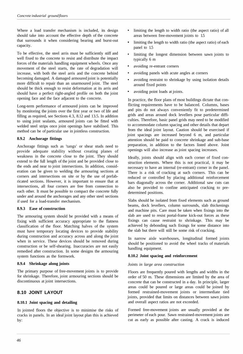
Concrete industrial ground floors
Where a load transfer mechanism is included, its designshould take into account the effective depth of the concretethat surrounds it when considering bearing and burst-outcapacity.
To be effective, the steel arris must be sufficiently stiff andwell fixed to the concrete to resist and distribute the impactforces of the materials handling equipment wheels. Once anymovement of the steel starts, the rate of degradation willincrease, with both the steel arris and the concrete behindbecoming damaged. A damaged armoured joint is potentiallymore difficult to repair than an unarmoured joint. The steelshould be thick enough to resist deformation at its arris andshould have a perfect right-angled profile on both the jointopening face and the face adjacent to the concrete.
Long-term performance of armoured joints can be improvedby monitoring the joints over the first year or two of life andfilling as required, see Sections 4.3, 8.12 and 13.5. In additionto using joint sealants, armoured joints can be fitted withwelded steel strips once joint openings have stabilised. Thismethod can be of particular use in jointless construction.
8.9.2 Anchorage fittings
Anchorage fittings such as 'tangs' or shear studs need toprovide adequate stability without creating planes ofweakness in the concrete close to the joint. They shouldextend to the full length of the joint and be provided close tothe ends and near to joint intersections. In addition, consid-eration can be given to welding the armouring sections atcorners and intersections on site or by the use of prefab-ricated sections. However, it is important to ensure that atintersections, all four corners are free from connection toeach other. It must be possible to compact the concrete fullyunder and around the anchorages and any other steel sectionsif used for a load-transfer mechanism.
8.9.3 Ease of construction
The armouring system should be provided with a means offixing with sufficient accuracy appropriate to the flatnessclassification of the floor. Matching halves of the systemmust have temporary locating devices to provide stabilityduring construction and accuracy across and along the jointwhen in service. These devices should be removed duringconstruction or be self-shearing. Inaccuracies are not easilyremedied after construction. In some designs the armouringsystem functions as the formwork.
8.9.4 Shrinkage along joints
The primary purpose of free-movement joints is to providefor shrinkage. Therefore, joint armouring sections should bediscontinuous at joint intersections.
8.10 JOINT LAYOUT
8.10.1 Joint spacing and detailing
In jointed floors the objective is to minimise the risks ofcracks in panels. In an ideal joint layout plan this is achievedby:
limiting the length to width ratio (the aspect ratio) of allareas between free-movement joints to 1.5
limiting the length to width ratio (the aspect ratio) of eachpanel to 1.5
limiting the longest dimension between sawn joints totypically 6 m
avoiding re-entrant corners
avoiding panels with acute angles at corners
avoiding restraint to shrinkage by using isolation detailsaround fixed points
avoiding point loads at joints.
In practice, the floor plans of most buildings dictate that con-flicting requirements have to be balanced. Columns, basesand pits do not always conveniently fit to predeterminedgrids and areas around dock levellers pose particular diffi-culties. Therefore, basic panel grids may need to be modifiedto accommodate column spacing and other details that departfrom the ideal joint layout. Caution should be exercised ifjoint spacings are increased beyond 6 m, and particularattention should be paid to concrete shrinkage and sub-basepreparation, in addition to the factors listed above. Jointopenings will also increase as joint spacing increases.
Ideally, joints should align with each corner of fixed con-struction elements. Where this is not practical, it may benecessary to have an internal (re-entrant) corner in the panel.There is a risk of cracking at such corners. This can bereduced or controlled by placing additional reinforcementbars diagonally across the corner. Additional saw cuts canalso be provided to confine anticipated cracking to pre-determined positions.
Slabs should be isolated from fixed elements such as groundbeams, dock levellers, column surrounds, slab thickeningsand machine pits. Care must be taken when fixings into theslab are used to resist portal-frame kick-out forces as thesefixings can cause restraint to shrinkage. This may beachieved by debonding such fixings for some distance intothe slab but there will still be some risk of cracking.
In narrow aisle warehouses, longitudinal formed jointsshould be positioned to avoid the wheel tracks of materialshandling equipment.
8.10.2 Joint spacing and reinforcement
Joints in large area construction
Floors are frequently poured with lengths and widths in theorder of 50 m. These dimensions are limited by the area ofconcrete that can be constructed in a day. In principle, largerareas could be poured or large areas could be joined byformed restrained-movement joints or intermediate tiedjoints, provided that limits on distances between sawn jointsand overall aspect ratios are not exceeded.
Formed free-movement joints are usually provided at theperimeter of each pour. Sawn restrained-movement joints arecut as early as possible after casting. A crack is induced
46
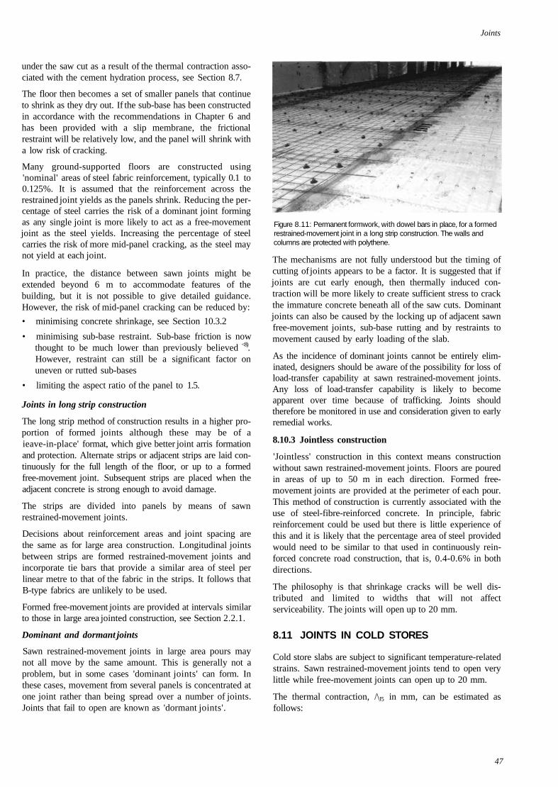
Joints
under the saw cut as a result of the thermal contraction asso-ciated with the cement hydration process, see Section 8.7.
The floor then becomes a set of smaller panels that continueto shrink as they dry out. If the sub-base has been constructedin accordance with the recommendations in Chapter 6 andhas been provided with a slip membrane, the frictionalrestraint will be relatively low, and the panel will shrink witha low risk of cracking.
Many ground-supported floors are constructed using'nominal' areas of steel fabric reinforcement, typically 0.1 to0.125%. It is assumed that the reinforcement across therestrained joint yields as the panels shrink. Reducing the per-centage of steel carries the risk of a dominant joint formingas any single joint is more likely to act as a free-movementjoint as the steel yields. Increasing the percentage of steelcarries the risk of more mid-panel cracking, as the steel maynot yield at each joint.
In practice, the distance between sawn joints might beextended beyond 6 m to accommodate features of thebuilding, but it is not possible to give detailed guidance.However, the risk of mid-panel cracking can be reduced by:
• minimising concrete shrinkage, see Section 10.3.2
• minimising sub-base restraint. Sub-base friction is nowthought to be much lower than previously believed <8).However, restraint can still be a significant factor onuneven or rutted sub-bases
• limiting the aspect ratio of the panel to 1.5.
Joints in long strip construction
The long strip method of construction results in a higher pro-portion of formed joints although these may be of aieave-in-place' format, which give better joint arris formationand protection. Alternate strips or adjacent strips are laid con-tinuously for the full length of the floor, or up to a formedfree-movement joint. Subsequent strips are placed when theadjacent concrete is strong enough to avoid damage.
The strips are divided into panels by means of sawnrestrained-movement joints.
Decisions about reinforcement areas and joint spacing arethe same as for large area construction. Longitudinal jointsbetween strips are formed restrained-movement joints andincorporate tie bars that provide a similar area of steel perlinear metre to that of the fabric in the strips. It follows thatB-type fabrics are unlikely to be used.
Formed free-movement joints are provided at intervals similarto those in large area jointed construction, see Section 2.2.1.
Dominant and dormant joints
Sawn restrained-movement joints in large area pours maynot all move by the same amount. This is generally not aproblem, but in some cases 'dominant joints' can form. Inthese cases, movement from several panels is concentrated atone joint rather than being spread over a number of joints.Joints that fail to open are known as 'dormant joints'.
Figure 8.11: Permanent formwork, with dowel bars in place, for a formedrestrained-movement joint in a long strip construction. The walls andcolumns are protected with polythene.
The mechanisms are not fully understood but the timing ofcutting of joints appears to be a factor. It is suggested that ifjoints are cut early enough, then thermally induced con-traction will be more likely to create sufficient stress to crackthe immature concrete beneath all of the saw cuts. Dominantjoints can also be caused by the locking up of adjacent sawnfree-movement joints, sub-base rutting and by restraints tomovement caused by early loading of the slab.
As the incidence of dominant joints cannot be entirely elim-inated, designers should be aware of the possibility for loss ofload-transfer capability at sawn restrained-movement joints.Any loss of load-transfer capability is likely to becomeapparent over time because of trafficking. Joints shouldtherefore be monitored in use and consideration given to earlyremedial works.
8.10.3 Jointless construction
'Jointless' construction in this context means constructionwithout sawn restrained-movement joints. Floors are pouredin areas of up to 50 m in each direction. Formed free-movement joints are provided at the perimeter of each pour.This method of construction is currently associated with theuse of steel-fibre-reinforced concrete. In principle, fabricreinforcement could be used but there is little experience ofthis and it is likely that the percentage area of steel providedwould need to be similar to that used in continuously rein-forced concrete road construction, that is, 0.4-0.6% in bothdirections.
The philosophy is that shrinkage cracks will be well dis-tributed and limited to widths that will not affectserviceability. The joints will open up to 20 mm.
8.11 JOINTS IN COLD STORES
Cold store slabs are subject to significant temperature-relatedstrains. Sawn restrained-movement joints tend to open verylittle while free-movement joints can open up to 20 mm.
The thermal contraction, /\J5 in mm, can be estimated asfollows:
47
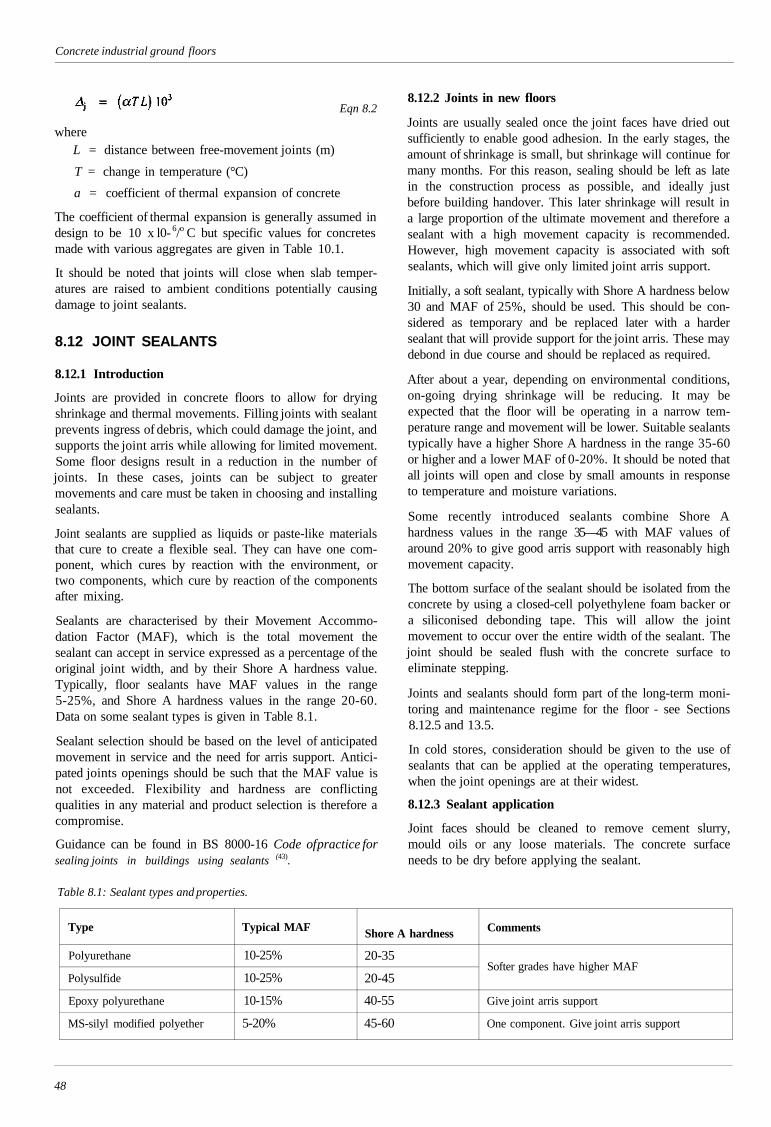
Concrete industrial ground floors
whereL = distance between free-movement joints (m)
T = change in temperature (°C)
a = coefficient of thermal expansion of concrete
The coefficient of thermal expansion is generally assumed indesign to be 10 x l0- 6/o C but specific values for concretesmade with various aggregates are given in Table 10.1.
It should be noted that joints will close when slab temper-atures are raised to ambient conditions potentially causingdamage to joint sealants.
8.12 JOINT SEALANTS
8.12.1 Introduction
Joints are provided in concrete floors to allow for dryingshrinkage and thermal movements. Filling joints with sealantprevents ingress of debris, which could damage the joint, andsupports the joint arris while allowing for limited movement.Some floor designs result in a reduction in the number ofjoints. In these cases, joints can be subject to greatermovements and care must be taken in choosing and installingsealants.
Joint sealants are supplied as liquids or paste-like materialsthat cure to create a flexible seal. They can have one com-ponent, which cures by reaction with the environment, ortwo components, which cure by reaction of the componentsafter mixing.
Sealants are characterised by their Movement Accommo-dation Factor (MAF), which is the total movement thesealant can accept in service expressed as a percentage of theoriginal joint width, and by their Shore A hardness value.Typically, floor sealants have MAF values in the range5-25%, and Shore A hardness values in the range 20-60.Data on some sealant types is given in Table 8.1.
Sealant selection should be based on the level of anticipatedmovement in service and the need for arris support. Antici-pated joints openings should be such that the MAF value isnot exceeded. Flexibility and hardness are conflictingqualities in any material and product selection is therefore acompromise.
Guidance can be found in BS 8000-16 Code of practice forsealing joints in buildings using sealants (43).
Table 8.1: Sealant types and properties.
Eqn 8.28.12.2 Joints in new floors
Joints are usually sealed once the joint faces have dried outsufficiently to enable good adhesion. In the early stages, theamount of shrinkage is small, but shrinkage will continue formany months. For this reason, sealing should be left as latein the construction process as possible, and ideally justbefore building handover. This later shrinkage will result ina large proportion of the ultimate movement and therefore asealant with a high movement capacity is recommended.However, high movement capacity is associated with softsealants, which will give only limited joint arris support.
Initially, a soft sealant, typically with Shore A hardness below30 and MAF of 25%, should be used. This should be con-sidered as temporary and be replaced later with a hardersealant that will provide support for the joint arris. These maydebond in due course and should be replaced as required.
After about a year, depending on environmental conditions,on-going drying shrinkage will be reducing. It may beexpected that the floor will be operating in a narrow tem-perature range and movement will be lower. Suitable sealantstypically have a higher Shore A hardness in the range 35-60or higher and a lower MAF of 0-20%. It should be noted thatall joints will open and close by small amounts in responseto temperature and moisture variations.
Some recently introduced sealants combine Shore Ahardness values in the range 35—45 with MAF values ofaround 20% to give good arris support with reasonably highmovement capacity.
The bottom surface of the sealant should be isolated from theconcrete by using a closed-cell polyethylene foam backer ora siliconised debonding tape. This will allow the jointmovement to occur over the entire width of the sealant. Thejoint should be sealed flush with the concrete surface toeliminate stepping.
Joints and sealants should form part of the long-term moni-toring and maintenance regime for the floor - see Sections8.12.5 and 13.5.
In cold stores, consideration should be given to the use ofsealants that can be applied at the operating temperatures,when the joint openings are at their widest.
8.12.3 Sealant application
Joint faces should be cleaned to remove cement slurry,mould oils or any loose materials. The concrete surfaceneeds to be dry before applying the sealant.
Type
Polyurethane
Polysulfide
Epoxy polyurethane
MS-silyl modified polyether
Typical MAF
10-25%
10-25%
10-15%
5-20%
Shore A hardness
20-35
20-45
40-55
45-60
Comments
Softer grades have higher MAF
Give joint arris support
One component. Give joint arris support
48
Joints
Sealants with higher Shore A hardness, as would be used forpermanent filling, transfer any applied load through ashearing action against the adhesive bond to the sides of thejoint. For a typical sawn joint 4-5 mm wide, the sealantshould be at least 20 mm deep.
The sealant should be allowed to cure fully before the jointis trafficked. The rate of cure of sealant is dependant on theambient temperature and the sealant type. Two-componentsystems require careful mixing but cure uniformly throughthe sealant bead and typically take 4-7 days to achieve fullcure. One-component sealants cure by reaction with atmos-pheric moisture or oxygen, forming a surface skin, whichgradually thickens. The time for full cure depends onhumidity and the dimensions of the sealant section. Thesealant manufacturer should be consulted.
8.12.4 Other filling systems
Highly compressed foam strips can be inserted into joints. Asthey do not rely on adhesion they can be inserted immediatelyafter the saw cutting operation. They also have goodmovement capacity but give only limited arris support. Arrissupport is a function of the material density in its compressedstate, so the support will reduce as the foam expands to fill awidening joint. They have potential to keep joints free ofdebris.
When drying shrinkage has reduced the joint is injected withepoxy resin, which fills the open cells of the foam and thevoid above the filler. The resin will also repair nominaldamage that has occurred to arrises and once levelled off willgive continuity across the joint. The use of epoxy resins mustbe compatible with any on-going movement of the joint.
Extruded plastic joint filler systems are also available. Theseare pressed into the joint after the joint arris has gained suf-ficient strength so as not to be damaged. They are designedto allow for a small amount of joint opening and give modestarris support. They prevent entry of dirt and debris. As jointsopen, they can be replaced with ones of wider section.
8.12.5 Maintaining joints
Owners and users of industrial facilities should include thefloor, especially the joints and sealants, in the programme ofroutine monitoring and maintenance of the facility. Main-taining joints effectively avoids the risk of joint failure:sealants should be inspected routinely and remedial actiontaken where failure has occurred. If repairs are not carried out,the joint sealant, arris, and surrounding floor will deterioratefurther, see Chapter 13. All joints will open and close slightlyin service, due to variations in temperature and moisturecontent. Therefore, repairs and replacements should preferablybe carried out when the floor is at its lowest temperature.
49
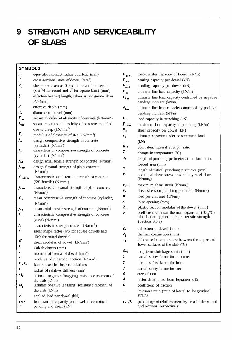
9 STRENGTH AND SERVICEABILITYOF SLABS
50
SYMBOLSequivalent contact radius of a load (mm)
cross-sectional area of dowel (mm2)
shear area taken as 0.9 x the area of the section( d 2/4 for round and d2 for square bars) (mm2)
effective bearing length, taken as not greater than8dA (mm)effective depth (mm)diameter of dowel (mm)secant modulus of elasticity of concrete (kN/mm2)secant modulus of elasticity of concrete modifieddue to creep (kN/mm2)modulus of elasticity of steel (N/mm2)design compressive strength of concrete(cylinder) (N/mm2)characteristic compressive strength of concrete(cylinder) (N/mm2)design axial tensile strength of concrete (N/mm2)design flexural strength of plain concrete(N/mm2)characteristic axial tensile strength of concrete(5% fractile) (N/mm2)characteristic flexural strength of plain concrete(N/mm2)mean compressive strength of concrete (cylinder)(N/mm2)mean axial tensile strength of concrete (N/mm2)characteristic compressive strength of concrete(cube) (N/mm2)characteristic strength of steel (N/mm2)shear shape factor (6/5 for square dowels and10/9 for round dowels)shear modulus of dowel (kN/mm2)slab thickness (mm)moment of inertia of dowel (mm4)modulus of subgrade reaction (N/mm3)factors used in shear calculationsradius of relative stiffness (mm)ultimate negative (hogging) resistance moment ofthe slab (kNm)ultimate positive (sagging) resistance moment ofthe slab (kNm)applied load per dowel (kN)load-transfer capacity per dowel in combinedbending and shear (kN)
load-transfer capacity of fabric (kN/m)
bearing capacity per dowel (kN)
bending capacity per dowel (kN)
ultimate line load capacity (kN/m)
ultimate line load capacity controlled by negativebending moment (kN/m)
ultimate line load capacity controlled by positivebending moment (kN/m)
load capacity in punching (kN)
maximum load capacity in punching (kN/m)
shear capacity per dowel (kN)
ultimate capacity under concentrated load
(kN)
equivalent flexural strength ratio
change in temperature (°C)
length of punching perimeter at the face of the
loaded area (mm)
length of critical punching perimeter (mm)additional shear stress provided by steel fibres(N/mm2)
maximum shear stress (N/mm2)shear stress on punching perimeter (N/mm2)
load per unit area (kN/m2)joint opening (mm)plastic section modulus of the dowel (mm3)coefficient of linear thermal expansion (10-6/°C)also faction applied to characteristic strength(Section 9.6.2)
deflection of dowel (mm)
thermal contraction (mm)difference in temperature between the upper andlower surfaces of the slab (°C)
long-term shrinkage strain (mm)partial safety factor for concrete
partial safety factor for loads
partial safety factor for steelcreep factor
factor determined from Equation 9.15
coefficient of friction
Poisson's ratio (ratio of lateral to longitudinalstrain)
percentage of reinforcement by area in the x- andy-directions, respectively
Strength and serviceability of slabs
9.1 INTRODUCTION
Traditionally, ground-supported slabs have been designed byelastic methods. The elastic analysis equations developed inthe 1920s by Westergaard (26. 27) are still used extensivelyworldwide for the design of ground-supported slabs. Suchslabs are relatively thick and so assessment of deflectionsand other in-service requirements has generally not beennecessary. As methods of analysis have developed, so slabshave become thinner. By using plastic methods of analysis,compatible with BS 8110(15) and the draft Eurocode 2(16), loadtransfer across joints and in-service requirements, such asdeflections and crack control, have become more significantand need to be evaluated.
The design approaches in this Chapter consider both theultimate and serviceability conditions, as outlined in Section9.3. Determination of the strength of the slab is based onplastic analysis. This requires that the slab has adequateductility, i.e. that it contains sufficient fibres or rein-forcement to provide adequate post-cracking behaviour.(Sections 9.4.2 and 9.4.3 give the required minimumamounts of steel and synthetic fibres, respectively, andAppendix E provides guid-ance on steel fabric.) The use ofplastic methods of analysis for plain concrete slabs, or forslabs with less than the minimum amount of fibres or rein-forcement in the concrete, is not appropriate due to the lackof ductility. Hence, they should still be designed by elasticmethods (see BCA Technical Report 550 (44) and InterimTechnical Note 11(45).
Equations are provided for the following:
bending capacity under point loads
capacity under line loads and uniformly distributed loads
load transfer across joints
punching
deflections.
For nominally loaded floors, reference may be made toSection 3.1. A worked example of the thickness design of aheavily loaded floor using the principles set out in thisChapter is given in Appendix B. This is extended inAppendix E to cover the use of fabric reinforcement.
9.2 UNITS
The following units are used for calculations:
forces and loads kN, kN/m, kN/m2
moments (bending) kNm
modulus of subgrade reaction N/mm3
radius of relative stiffness mm
slab depth mm
stresses and strengths N/mm2
unit mass kg/m3
unit weight kN/m3
9.3 DESIGN PRINCIPLES AND CRITERIA
9.3.1 Introduction
The design procedure is in limit state format, in line withmodern codes such as BS 8110, Structural use of concrete(15)
and the draft Eurocode 2, Design of concrete structures (l6).Partial safety factors are applied to the loads and to the prop-erties of the materials. Design checks are carried out on boththe strength and serviceability of the slab. The designformulae are, where appropriate, similar to those used in thedraft Eurocode 2. However, it must be emphasised thatneither the Eurocode nor the associated National Annex arecurrently finalised. Hence, the expressions used may bechanged in the final, implemented versions, which maynecessitate a review of the proposed design clauses. It shouldbe noted that there are some differences in terminologybetween current British Codes and the draft Eurocodes,namely:
Loads are referred to as actions
Superimposed loads are variable actions, Q
Self-weight and dead loads are permanent actions, G.
9.3.2 Ultimate limit state
The parameters controlling the design of ground-supportedslabs at the ultimate limit state are not as clear-cut as forgeneral reinforced concrete design, where 'ultimate' refers tothe strength of the structure and 'serviceability' to the limi-tation of crack widths, deflections etc. For ground-supportedslabs, two ultimate strength modes of failure of the concreteslab are possible, namely flexure (bending) and localpunching. Slab design for flexure at the ultimate limit state isbased on yield line theory, which requires adequate ductilityto assume plastic behaviour. (Ductility requirements are dis-cussed in Section 9.4 and Appendix E.) At the ultimate limitstate, the bending moment along the sagging yield lines maybe assumed to be the full plastic (or residual post-cracking)value. However, a principal requirement in the design ofground-supported slabs is the avoidance of cracks on theupper surface. Hence, at the ultimate limit state the bendingmoment of the slab along the hogging yield lines is limitedto the design cracking moment of the concrete, with thepartial safety factors appropriate to the ultimate limit state.Clearly there is a requirement for sufficient rotation capacityof the sagging yield lines so that the hogging momentcapacity is mobilised.
In some circumstances, shrinkage and temperature changesmay lead to significant tensile stresses in slabs. This couldcause problems in any area in which the applied loadingleads to a significant hogging moment, such as areas betweenuniformly distributed loads, see Section 9.9.5. It could alsoapply to aisles between racking, where the pattern of indi-vidual leg loads can be considered to be equivalent to stripsof uniformly distributed loading on either side of the aisle. Inthese cases the assumed flexural tensile strength of theconcrete, and hence the cracking moment, should be reducedby an appropriate amount, see Section 9.12.3.
51
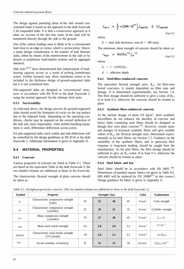
Concrete industrial ground floors
The design against punching shear of the slab around con-centrated loads is based on the approach in the draft Eurocode2 for suspended slabs. It is thus a conservative approach as ittakes no account of the fact that some of the load will betransferred directly through the slab to the ground.
One of the critical loading cases is likely to be a concentratedload close to an edge or corner, which is across joints. Hence,a major design consideration is the transfer of load betweenslabs, either by means of the reinforcement in the slab or bydowels or proprietary load-transfer systems and by aggregateinterlock.
Slab tests (46.47) have demonstrated that enhancement of load-bearing capacity occurs as a result of arching (membrane)action. Further research may allow membrane action to beincluded in the thickness design of ground-supported slabsbut it is not considered here.
Pile-supported slabs are designed as 'conventional' struc-tures in accordance with BS 8110 or the draft Eurocode 2,using the normal approach for the ultimate limit state.
9.3.3 Serviceability
As indicated above, the design process for ground-supportedslabs should avoid the formation of cracks on the top surfacedue to the imposed loads. Depending on the operating con-ditions, checks may be required on the overall deflection ofthe slab and, more importantly, when mobile handling equip-ment is used, differential deflections across joints.
For pile-supported slabs crack widths and slab deflections willbe controlled by the design guidelines in BS 8110 or the draftEurocode 2. Additional information is given in Appendix D.
9.4 MATERIAL PROPERTIES
9.4.1 Concrete
Various properties of concrete are listed in Table 9.1. Theseare based on the equivalent Table in the draft Eurocode 2; thetwo shaded columns are additional to those in the Eurocode.
The characteristic flexural strength of plain concrete shouldbe taken as:
Eqn 9.1
where
h = total slab thickness, mm (h > 100 mm).
The minimum shear strength of concrete should be taken as:
Eqn 9.2
where
k1 = 1 +(200/d)0 .5
d = effective depth
9.4.2 Steel-fibre-reinforced concrete
The equivalent flexural strength ratio, Re,3, for fibre-rein-forced concretes, is mainly dependent on fibre type anddosage. It is determined experimentally, see Section 7.4.The fibre dosage should be sufficient to give a value of Re,3
of at least 0.3, otherwise the concrete should be treated asplain.
9.4.3 Synthetic-fibre-reinforced concrete
At the normal dosage of about 0.9 kg/m3, short syntheticmicrofibres do not enhance the ductility of concrete andhence slabs containing such fibres should be designed asthough they were plain concrete (47). However, certain typesand dosages of structural synthetic fibres will give suitablevalues of Re3 , the flexural strength ratio, determined experi-mentally as for steel fibres, see Section 7.5. Guidance on thesuitability of the synthetic fibres, and in particular theirresponse to long-term loading, should be sought from themanufacturer. As for steel fibres, the fibre dosage should besufficient to give an Re,3 value of at least 0.3, otherwise theconcrete should be treated as plain.
9.4.4 Steel fabric and bar
Steel fabric should be in accordance with BS 4483 (39).Dimensions of standard square fabrics are given in Table 9.2.(BS 4483 will be replaced by EN 10080(37) in due course.)Design guidance for fabric is given in Appendix E.
Table 9.1: Strength properties for concrete. (The two shaded columns are additional to those in the draft Eurocode 2.)
Symbol
fcu
fck
fcm
fctm
fctk(0.05)
Property
Characteristic compressive strength(cube)
Characteristic compressive strength(cylinder)
Mean compressive strength(cylinder)
Mean axial tensile strength
Characteristic axial tensile strength(5% fractile)
Secant modulus of elasticity
Strength class
30
25
33
2.6
1.8
31
35
28
37
2.8
2.0
32
40
32
40
3.0
2.1
33
45
35
43
3.2
2.2
34
Units
N/mm2
N/mm2
N/mm2
N/mm2
N/mm2
kN/mm2
Explanation
Cube strength
Cylinder strength
f c k +8
0.3 fck 2/3
0.7fctm
22(fcm/10)0.3
52
cmE
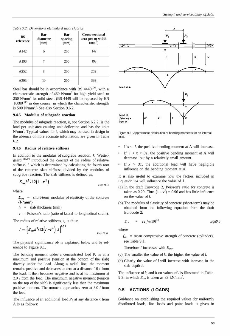
Strength and serviceability of slabs
Table 9.2: Dimensions of standard square fabrics
BSreference
A142
A193
A252
A393
Bardiameter
(mm)
6
7
8
10
Barspacing(mm)
200
200
200
200
Cross-sectionalarea per m width
(mm2)
142
193
252
393
Steel bar should be in accordance with BS 4449 (36), with acharacteristic strength of 460 N/mm2 for high yield steel or250 N/mm2 for mild steel. (BS 4449 will be replaced by EN10080 (37) in due course, in which the characteristic strengthis 500 N/mm2.) See also Section 9.6.2.
9.4.5 Modulus of subgrade reaction
The modulus of subgrade reaction, k, see Section 6.2.2, is theload per unit area causing unit deflection and has the unitsN/mm3. Typical values for k, which may be used in design inthe absence of more accurate information, are given in Table6.2.
9.4.6 Radius of relative stiffness
In addition to the modulus of subgrade reaction, k, Wester-gaard (26,27) introduced the concept of the radius of relativestiffness, l, which is determined by calculating the fourth rootof the concrete slab stiffness divided by the modulus ofsubgrade reaction. The slab stiffness is defined as:
Eqn 9.3
where
short-term modulus of elasticity of the concrete
h = slab thickness (mm)
v = Poisson's ratio (ratio of lateral to longitudinal strain).
The radius of relative stiffness, /, is thus:
Eqn 9.4
The physical significance of/ is explained below and by ref-erence to Figure 9.1.
The bending moment under a concentrated load P, is at amaximum and positive (tension at the bottom of the slab)directly under the load. Along a radial line, the momentremains positive and decreases to zero at a distance 1.0 / fromthe load. It then becomes negative and is at its maximum at2.0 l from the load. The maximum negative moment (tensionon the top of the slab) is significantly less than the maximumpositive moment. The moment approaches zero at 3.0 / fromthe load.
The influence of an additional load P2 at any distance x fromA is as follows:
Figure 9.1: Approximate distribution of bending moments for an internalload.
If x < l, the positive bending moment at A will increase.
If l < x < 31, the positive bending moment at A willdecrease, but by a relatively small amount.
If x > 31, the additional load will have negligibleinfluence on the bending moment at A.
It is also useful to examine how the factors included inEquation 9.4 will influence the value of l.
(a) In the draft Eurocode 2, Poisson's ratio for concrete istaken as 0.20. Thus (1 - v2) = 0.96 and has little influenceon the value of l.
(b) The modulus of elasticity of concrete (short-term) may beobtained from the following equation from the draftEurocode 2:
Ecm = 22(fcm/10)0.3 Eqn9.5
where
fcm = mean compressive strength of concrete (cylinder),see Table 9.1.
Therefore l increases with Ecm.
(c) The smaller the value of k, the higher the value of l.
(d) Clearly the value of l will increase with increase in theslab depth h.
The influence of k; and h on values of l is illustrated in Table9.3, in which Ecm is taken as 33 kN/mm2.
9.5 ACTIONS (LOADS)
Guidance on establishing the required values for uniformlydistributed loads, line loads and point loads is given in
53
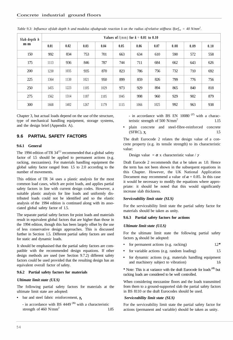
Concrete industrial ground floors
Chapter 3, but actual loads depend on the use of the structure,type of mechanical handling equipment, storage systems,and the design brief (Appendix A).
9.6 PARTIAL SAFETY FACTORS
9.6.1 General
The 1994 edition of TR 34(1) recommended that a global safetyfactor of 1.5 should be applied to permanent actions (e.g.racking, mezzanines). For materials handling equipment theglobal safety factor ranged from 1.5 to 2.0 according to thenumber of movements.
This edition of TR 34 uses a plastic analysis for the mostcommon load cases, which are point loads, and applies partialsafety factors in line with current design codes. However, asuitable plastic analysis for line loads and uniformly dis-tributed loads could not be identified and so the elasticanalysis of the 1994 edition is continued along with its asso-ciated global safety factor of 1.5.
The separate partial safety factors for point loads and materialsresult in equivalent global factors that are higher than those inthe 1994 edition, though this has been largely offset by the useof less conservative design approaches. This is discussedfurther in Section 1.5. Different partial safety factors are usedfor static and dynamic loads.
It should be emphasised that the partial safety factors are com-patible with the recommended design equations. If otherdesign methods are used (see Section 9.7.2) different safetyfactors could be used provided that the resulting design has anequivalent overall factor of safety.
9.6.2 Partial safety factors for materials
Ultimate limit state (ULS)
The following partial safety factors for materials at theultimate limit state are adopted:
bar and steel fabric reinforcement,
- in accordance with BS 4449 (36) with a characteristicstrength of 460 N/mm2 1.05
- in accordance with BS EN 10080 (37) with a charac-teristic strength of 500 N/mm2 1.15
plain concrete and steel-fibre-reinforced concrete(SFRC), 1.5
The draft Eurocode 2 relates the design value of a con-crete property (e.g. its tensile strength) to its characteristicvalue:
Design value = x characteristic value /
Draft Eurocde 2 recommends that a be taken as 1.0. Hencethe term has not been shown in the subsequent equations inthis Chapter. However, the UK National ApplicationDocument may recommend a value of = 0.85. In this caseit would be necessary to modify the equations where appro-priate: it should be noted that this would significantlyincrease slab thickness.
Serviceability limit state (SLS)
For the serviceability limit state the partial safety factor formaterials should be taken as unity.
9.6.3 Partial safety factors for actions
Ultimate limit state (ULS)
For the ultimate limit state the following partial safetyfactors should be adopted:
for permanent actions (e.g. racking) 1.2
for variable actions (e.g. random loading) 1.5
for dynamic actions (e.g. materials handling equipmentand machinery subject to vibration) 1.6
Note: This is at variance with the draft Eurocode for loads (48) butracking loads are considered to be well controlled.
When considering mezzanine floors and the loads transmittedfrom them to a ground-supported slab the partial safety factorsin BS 8110 or the draft Eurocodes should be used.
Serviceability limit state (SLS)
For the serviceability limit state the partial safety factor foractions (permanent and variable) should be taken as unity.
54
S l a b d e p t h hm m
150
175
200
225
250
275
300
Values of l ( m m ) for k = 0.01 to 0.10
0.01
992
1113
1230
1364
1455
1562
1668
0.02
834
936
1035
1130
1223
1314
1402
0.03
753
846
935
1021
1105
1187
1267
0.04
701
787
870
950
1029
1105
1179
0.05
663
744
823
899
973
1045
1115
0.06
634
711
786
859
929
998
1066
0.07
610
684
756
826
894
960
1025
0 .08
590
662
732
799
865
929
992
0 .09
572
643
710
776
840
902
963
0 .10
558
626
692
756
818
879
938
Table 9.3: Influence of slab depth h and modulus ofsubgrade reaction k on the radius of relative stiffness lforfcu = 40 N/mm2.
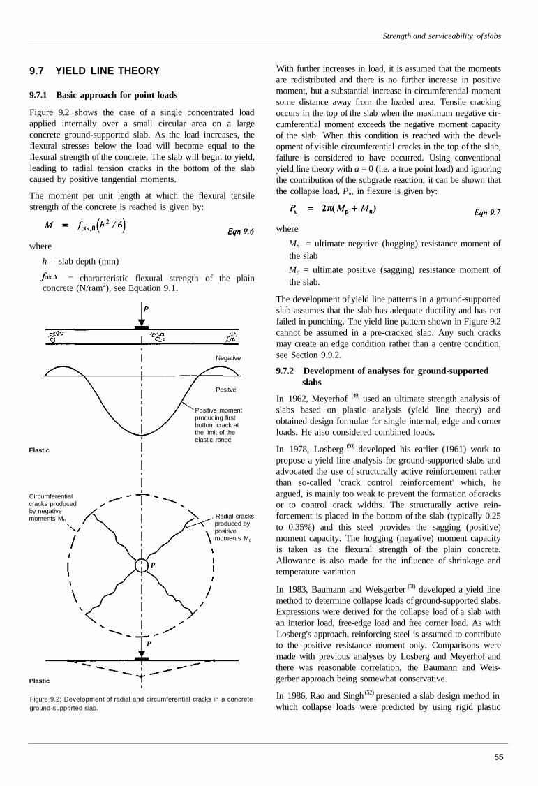
Strength and serviceability of slabs
9.7 YIELD LINE THEORY
9.7.1 Basic approach for point loads
Figure 9.2 shows the case of a single concentrated loadapplied internally over a small circular area on a largeconcrete ground-supported slab. As the load increases, theflexural stresses below the load will become equal to theflexural strength of the concrete. The slab will begin to yield,leading to radial tension cracks in the bottom of the slabcaused by positive tangential moments.
The moment per unit length at which the flexural tensilestrength of the concrete is reached is given by:
where
h = slab depth (mm)
= characteristic flexural strength of the plainconcrete (N/ram2), see Equation 9.1.
Negative
Positve
Positive momentproducing firstbottom crack atthe limit of theelastic range
Elastic
Circumferentialcracks producedby negativemoments Mn
. Radial cracksproduced bypositivemoments Mp
Plastic
P
P
Figure 9.2: Development of radial and circumferential cracks in a concreteground-supported slab.
With further increases in load, it is assumed that the momentsare redistributed and there is no further increase in positivemoment, but a substantial increase in circumferential momentsome distance away from the loaded area. Tensile crackingoccurs in the top of the slab when the maximum negative cir-cumferential moment exceeds the negative moment capacityof the slab. When this condition is reached with the devel-opment of visible circumferential cracks in the top of the slab,failure is considered to have occurred. Using conventionalyield line theory with a = 0 (i.e. a true point load) and ignoringthe contribution of the subgrade reaction, it can be shown thatthe collapse load, Pu, in flexure is given by:
where
Mn = ultimate negative (hogging) resistance moment ofthe slab
Mp = ultimate positive (sagging) resistance moment ofthe slab.
The development of yield line patterns in a ground-supportedslab assumes that the slab has adequate ductility and has notfailed in punching. The yield line pattern shown in Figure 9.2cannot be assumed in a pre-cracked slab. Any such cracksmay create an edge condition rather than a centre condition,see Section 9.9.2.
9.7.2 Development of analyses for ground-supportedslabs
In 1962, Meyerhof (49) used an ultimate strength analysis ofslabs based on plastic analysis (yield line theory) andobtained design formulae for single internal, edge and cornerloads. He also considered combined loads.
In 1978, Losberg (50) developed his earlier (1961) work topropose a yield line analysis for ground-supported slabs andadvocated the use of structurally active reinforcement ratherthan so-called 'crack control reinforcement' which, heargued, is mainly too weak to prevent the formation of cracksor to control crack widths. The structurally active rein-forcement is placed in the bottom of the slab (typically 0.25to 0.35%) and this steel provides the sagging (positive)moment capacity. The hogging (negative) moment capacityis taken as the flexural strength of the plain concrete.Allowance is also made for the influence of shrinkage andtemperature variation.
In 1983, Baumann and Weisgerber (5I) developed a yield linemethod to determine collapse loads of ground-supported slabs.Expressions were derived for the collapse load of a slab withan interior load, free-edge load and free corner load. As withLosberg's approach, reinforcing steel is assumed to contributeto the positive resistance moment only. Comparisons weremade with previous analyses by Losberg and Meyerhof andthere was reasonable correlation, the Baumann and Weis-gerber approach being somewhat conservative.
In 1986, Rao and Singh (52) presented a slab design method inwhich collapse loads were predicted by using rigid plastic
55
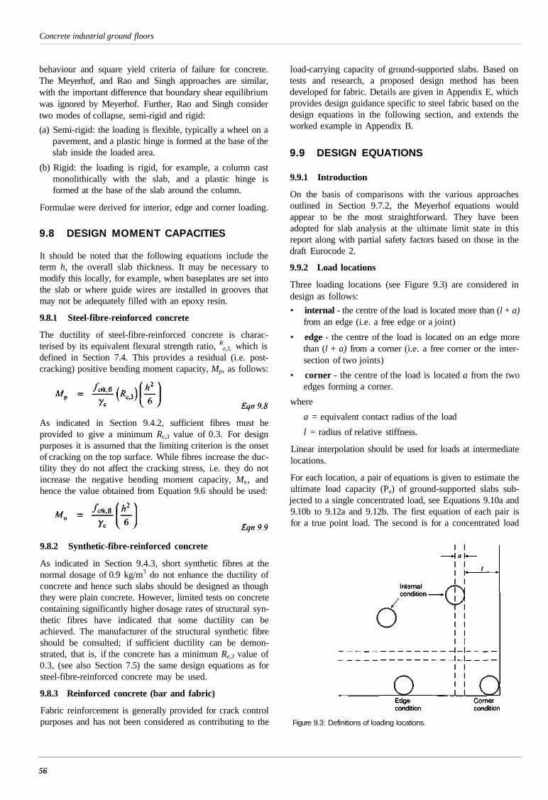
Concrete industrial ground floors
behaviour and square yield criteria of failure for concrete.The Meyerhof, and Rao and Singh approaches are similar,with the important difference that boundary shear equilibriumwas ignored by Meyerhof. Further, Rao and Singh considertwo modes of collapse, semi-rigid and rigid:
(a) Semi-rigid: the loading is flexible, typically a wheel on apavement, and a plastic hinge is formed at the base of theslab inside the loaded area.
(b) Rigid: the loading is rigid, for example, a column castmonolithically with the slab, and a plastic hinge isformed at the base of the slab around the column.
Formulae were derived for interior, edge and corner loading.
9.8 DESIGN MOMENT CAPACITIES
It should be noted that the following equations include theterm h, the overall slab thickness. It may be necessary tomodify this locally, for example, when baseplates are set intothe slab or where guide wires are installed in grooves thatmay not be adequately filled with an epoxy resin.
9.8.1 Steel-fibre-reinforced concrete
The ductility of steel-fibre-reinforced concrete is charac-terised by its equivalent flexural strength ratio, R
e,3, which isdefined in Section 7.4. This provides a residual (i.e. post-cracking) positive bending moment capacity, Mp, as follows:
As indicated in Section 9.4.2, sufficient fibres must beprovided to give a minimum Rc,3 value of 0.3. For designpurposes it is assumed that the limiting criterion is the onsetof cracking on the top surface. While fibres increase the duc-tility they do not affect the cracking stress, i.e. they do notincrease the negative bending moment capacity, Mn , andhence the value obtained from Equation 9.6 should be used:
9.8.2 Synthetic-fibre-reinforced concrete
As indicated in Section 9.4.3, short synthetic fibres at thenormal dosage of 0.9 kg/m3 do not enhance the ductility ofconcrete and hence such slabs should be designed as thoughthey were plain concrete. However, limited tests on concretecontaining significantly higher dosage rates of structural syn-thetic fibres have indicated that some ductility can beachieved. The manufacturer of the structural synthetic fibreshould be consulted; if sufficient ductility can be demon-strated, that is, if the concrete has a minimum Re,3 value of0.3, (see also Section 7.5) the same design equations as forsteel-fibre-reinforced concrete may be used.
9.8.3 Reinforced concrete (bar and fabric)
Fabric reinforcement is generally provided for crack controlpurposes and has not been considered as contributing to the
load-carrying capacity of ground-supported slabs. Based ontests and research, a proposed design method has beendeveloped for fabric. Details are given in Appendix E, whichprovides design guidance specific to steel fabric based on thedesign equations in the following section, and extends theworked example in Appendix B.
9.9 DESIGN EQUATIONS
9.9.1 Introduction
On the basis of comparisons with the various approachesoutlined in Section 9.7.2, the Meyerhof equations wouldappear to be the most straightforward. They have beenadopted for slab analysis at the ultimate limit state in thisreport along with partial safety factors based on those in thedraft Eurocode 2.
9.9.2 Load locations
Three loading locations (see Figure 9.3) are considered indesign as follows:
• internal - the centre of the load is located more than (l + a)from an edge (i.e. a free edge or a joint)
• edge - the centre of the load is located on an edge morethan (l + a) from a corner (i.e. a free corner or the inter-section of two joints)
• corner - the centre of the load is located a from the twoedges forming a corner.
where
a = equivalent contact radius of the load
l = radius of relative stiffness.
Linear interpolation should be used for loads at intermediatelocations.
For each location, a pair of equations is given to estimate theultimate load capacity (Pu) of ground-supported slabs sub-jected to a single concentrated load, see Equations 9.10a and9.10b to 9.12a and 9.12b. The first equation of each pair isfor a true point load. The second is for a concentrated load
Figure 9.3: Definitions of loading locations.
56
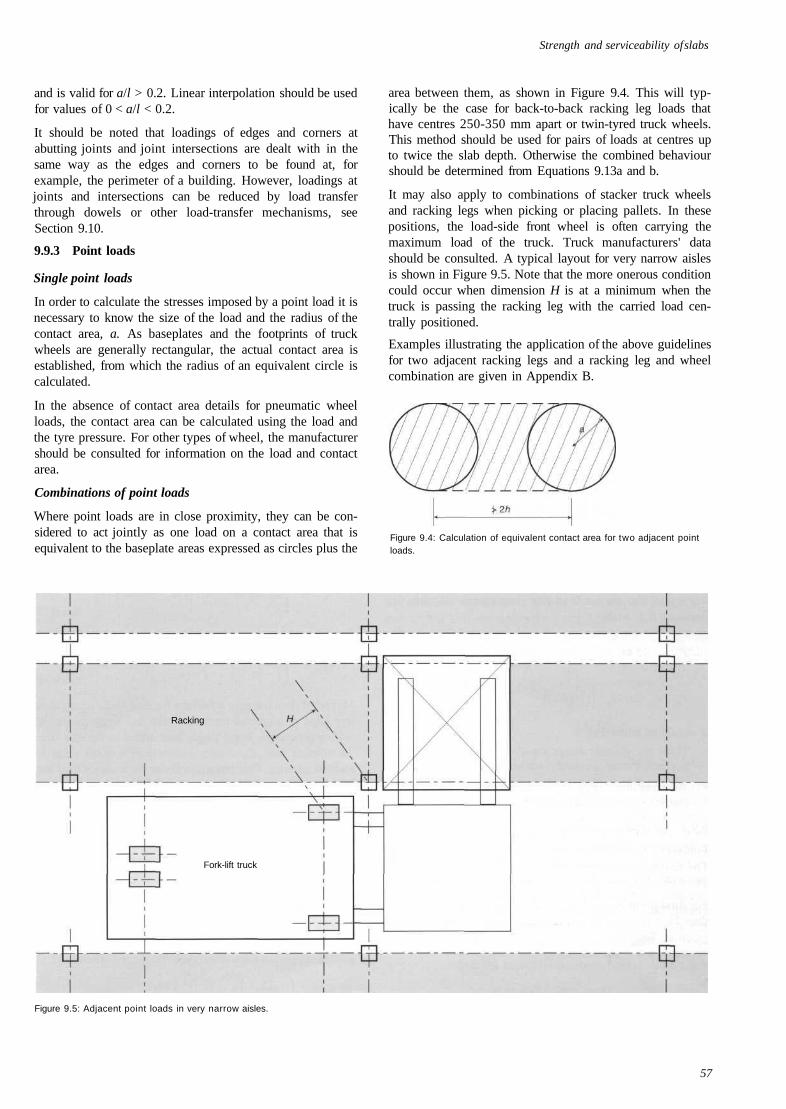
Strength and serviceability of slabs
and is valid for a/l > 0.2. Linear interpolation should be usedfor values of 0 < a/l < 0.2.
It should be noted that loadings of edges and corners atabutting joints and joint intersections are dealt with in thesame way as the edges and corners to be found at, forexample, the perimeter of a building. However, loadings atjoints and intersections can be reduced by load transferthrough dowels or other load-transfer mechanisms, seeSection 9.10.
9.9.3 Point loads
Single point loads
In order to calculate the stresses imposed by a point load it isnecessary to know the size of the load and the radius of thecontact area, a. As baseplates and the footprints of truckwheels are generally rectangular, the actual contact area isestablished, from which the radius of an equivalent circle iscalculated.
In the absence of contact area details for pneumatic wheelloads, the contact area can be calculated using the load andthe tyre pressure. For other types of wheel, the manufacturershould be consulted for information on the load and contactarea.
Combinations of point loads
Where point loads are in close proximity, they can be con-sidered to act jointly as one load on a contact area that isequivalent to the baseplate areas expressed as circles plus the
area between them, as shown in Figure 9.4. This will typ-ically be the case for back-to-back racking leg loads thathave centres 250-350 mm apart or twin-tyred truck wheels.This method should be used for pairs of loads at centres upto twice the slab depth. Otherwise the combined behaviourshould be determined from Equations 9.13a and b.
It may also apply to combinations of stacker truck wheelsand racking legs when picking or placing pallets. In thesepositions, the load-side front wheel is often carrying themaximum load of the truck. Truck manufacturers' datashould be consulted. A typical layout for very narrow aislesis shown in Figure 9.5. Note that the more onerous conditioncould occur when dimension H is at a minimum when thetruck is passing the racking leg with the carried load cen-trally positioned.
Examples illustrating the application of the above guidelinesfor two adjacent racking legs and a racking leg and wheelcombination are given in Appendix B.
Figure 9.4: Calculation of equivalent contact area for two adjacent pointloads.
Figure 9.5: Adjacent point loads in very narrow aisles.
57
Fork-lift truck
Racking
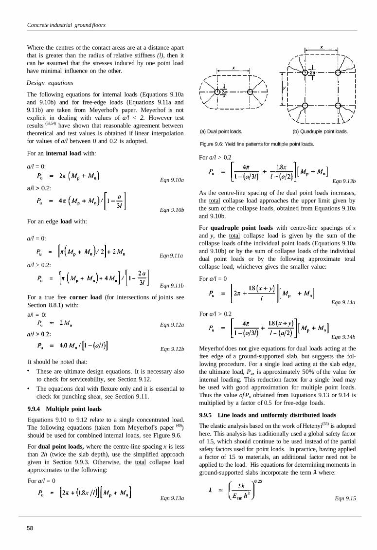
Concrete industrial ground floors
Where the centres of the contact areas are at a distance apartthat is greater than the radius of relative stiffness (l), then itcan be assumed that the stresses induced by one point loadhave minimal influence on the other.
Design equations
The following equations for internal loads (Equations 9.10aand 9.10b) and for free-edge loads (Equations 9.11a and9.11b) are taken from Meyerhof's paper. Meyerhof is notexplicit in dealing with values of a/l < 2. However testresults (53,54) have shown that reasonable agreement betweentheoretical and test values is obtained if linear interpolationfor values of a/l between 0 and 0.2 is adopted.
For an internal load with:
For an edge load with:
Eqn 9.10a
Eqn 9.10b
a/l = 0:
a/l > 0.2:
a/l = 0:
a/l > 0.2:
Eqn 9.11a
Eqn 9.11b
For a true free corner load (for intersections of joints seeSection 8.8.1) with:
a/l = 0:
Eqn 9.12a
Eqn 9.12b
It should be noted that:
These are ultimate design equations. It is necessary alsoto check for serviceability, see Section 9.12.
The equations deal with flexure only and it is essential tocheck for punching shear, see Section 9.11.
9.9.4 Multiple point loads
Equations 9.10 to 9.12 relate to a single concentrated load.The following equations (taken from Meyerhof's paper (49))should be used for combined internal loads, see Figure 9.6.
For dual point loads, where the centre-line spacing x is lessthan 2h (twice the slab depth), use the simplified approachgiven in Section 9.9.3. Otherwise, the total collapse loadapproximates to the following:
For a/l = 0
Eqn 9.13a
(a) Dual point loads. (b) Quadruple point loads.
Figure 9.6: Yield line patterns for multiple point loads.
For a/l > 0.2
Eqn 9.13b
As the centre-line spacing of the dual point loads increases,the total collapse load approaches the upper limit given bythe sum of the collapse loads, obtained from Equations 9.10aand 9.10b.
For quadruple point loads with centre-line spacings of xand y, the total collapse load is given by the sum of thecollapse loads of the individual point loads (Equations 9.10aand 9.10b) or by the sum of collapse loads of the individualdual point loads or by the following approximate totalcollapse load, whichever gives the smaller value:
For a/l = 0
Eqn 9.14a
For a/l > 0.2
Eqn 9.14b
Meyerhof does not give equations for dual loads acting at thefree edge of a ground-supported slab, but suggests the fol-lowing procedure. For a single load acting at the slab edge,the ultimate load, Pu, is approximately 50% of the value forinternal loading. This reduction factor for a single load maybe used with good approximation for multiple point loads.Thus the value of Pu obtained from Equations 9.13 or 9.14 ismultiplied by a factor of 0.5 for free-edge loads.
9.9.5 Line loads and uniformly distributed loads
The elastic analysis based on the work of Hetenyi(55) is adoptedhere. This analysis has traditionally used a global safety factorof 1.5, which should continue to be used instead of the partialsafety factors used for point loads. In practice, having applieda factor of 1.5 to materials, an additional factor need not beapplied to the load. His equations for determining moments inground-supported slabs incorporate the term where:
Eqn 9.15
58
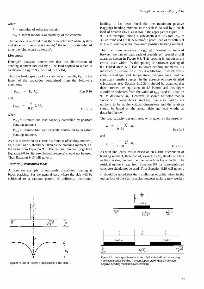
Strength and serviceability of slabs
where
k = modulus of subgrade reaction
Ecm = secant modulus of elasticity of the concrete
The factor λ is referred to as the 'characteristic' of the systemand since its dimension is (length)-1 the term ( l / λ) is referredto as the 'characteristic length'.
Line loads
Hetenyi's analysis determined that the distribution ofbending moment induced by a line load applied to a slab isas shown in Figure 9.7, with Mn = 0.2 lMp.
Thus the load capacity of the slab per unit length, Plin, is thelesser of the capacities determined from the followingequations:
Plin,p = 4λ Mp Eqn 9.16
Eqn 9.17
Plin,p = ultimate line load capacity controlled by positivebending moment
Plin,n = ultimate line load capacity controlled by negativebending moment.
As this is based on an elastic distribution of bending moment,Mp as well as Mn should be taken as the cracking moment, i.e.the value from Equation 9.6. The residual moment (e.g. fromEquation 9.8 for fibre-reinforced concrete) should not be used.Thus Equation 9.16 will govern.
Uniformly distributed loads
A common example of uniformly distributed loading isblock stacking. For the general case where the slab will besubjected to a random pattern of uniformly distributed
and
loading, it has been found that the maximum positive(sagging) bending moment in the slab is caused by a patchload of breadth (π/2λ) as shown in the upper part of Figure9.8. For example, taking a slab depth h = 175 mm, Ecm =33 kN/mm2 and k = 0.05 N/mm3, a patch load of breadth p/2l= 1.64 m will cause the maximum positive bending moment.
The maximum negative (hogging) moment is inducedbetween the pair of loads each of breadth p/l spaced at p/2lapart, as shown in Figure 9.8. This spacing is known as thecritical aisle width. Wider spacing or narrower spacing ofthe loaded areas will lead to lower bending moments. Asindicated in Section 9.3.2, this is a situation in which differ-ential shrinkage and temperature changes may lead tosignificant tensile stresses. In the absence of more detailedcalculations (see Section 9.12.3) it should be assumed thatthese stresses are equivalent to 1.5 N/mm2 and this figureshould be deducted from the value of fak,fl used in Equation9.6 to determine Mn. However, it should be noted that infloors with heavy block stacking, the aisle widths areunlikely to be at the critical dimensions and the analysisshould be based on the actual aisle and load widths asdescribed below.
The load capacity per unit area, w, is given by the lesser of:
and
1
0.161
λ2 Mn
1
0.168
Eqn 9.18
Eqn 9.19
As with line loads, this is based on an elastic distribution ofbending moment, therefore Mp as well as Mn should be takenas the cracking moment, i.e. the value from Equation 9.6. Theresidual moment (e.g. from Equation 9.8 for fibre-reinforcedconcrete) should not be used. Thus Equation 9.19 will govern.
It should be noted that the installation of guide wires in thetop surface of the slab in aisles between racking may weaken
Figure 9.7: Use of Hetenyi's equations for a line load P.
Load w
π2λ
πλ
Load w
Figure 9.8: Loading patterns for uniformly distributed load, w, causingmaximum positive bending moment (upper drawing) and maximumnegative bending moment (lower drawing).
59
w =
w = λ2 Mp
Plin,n =4
0.21λ Mn
where
πλ
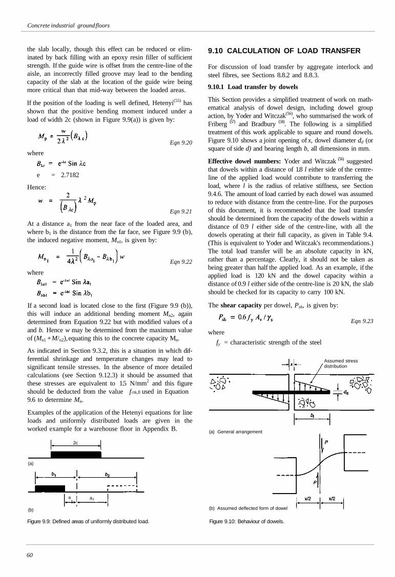
Concrete industrial ground floors
the slab locally, though this effect can be reduced or elim-inated by back filling with an epoxy resin filler of sufficientstrength. If the guide wire is offset from the centre-line of theaisle, an incorrectly filled groove may lead to the bendingcapacity of the slab at the location of the guide wire beingmore critical than that mid-way between the loaded areas.
If the position of the loading is well defined, Hetenyi(55) hasshown that the positive bending moment induced under aload of width 2c (shown in Figure 9.9(a)) is given by:
Eqn 9.20
where
e = 2.7182
Hence:
Eqn 9.21
At a distance a1 from the near face of the loaded area, andwhere b1 is the distance from the far face, see Figure 9.9 (b),the induced negative moment, Mnl, is given by:
Eqn 9.22
where
If a second load is located close to the first (Figure 9.9 (b)),this will induce an additional bending moment Mn2, againdetermined from Equation 9.22 but with modified values of aand b. Hence w may be determined from the maximum valueof (Mn1 + M/n2), equating this to the concrete capacity Mn.
As indicated in Section 9.3.2, this is a situation in which dif-ferential shrinkage and temperature changes may lead tosignificant tensile stresses. In the absence of more detailedcalculations (see Section 9.12.3) it should be assumed thatthese stresses are equivalent to 1.5 N/mm2 and this figureshould be deducted from the value f ctk,fl used in Equation9.6 to determine Mn.
Examples of the application of the Hetenyi equations for lineloads and uniformly distributed loads are given in theworked example for a warehouse floor in Appendix B.
2c
(a)
a1
a2
(b)
Figure 9.9: Defined areas of uniformly distributed load.
9.10 CALCULATION OF LOAD TRANSFER
For discussion of load transfer by aggregate interlock andsteel fibres, see Sections 8.8.2 and 8.8.3.
9.10.1 Load transfer by dowels
This Section provides a simplified treatment of work on math-ematical analysis of dowel design, including dowel groupaction, by Yoder and Witczak(56), who summarised the work ofFriberg (57) and Bradbury (58). The following is a simplifiedtreatment of this work applicable to square and round dowels.Figure 9.10 shows a joint opening of x, dowel diameter dd (orsquare of side d) and bearing length b, all dimensions in mm.
Effective dowel numbers: Yoder and Witczak (56) suggestedthat dowels within a distance of 1.8 l either side of the centre-line of the applied load would contribute to transferring theload, where l is the radius of relative stiffness, see Section9.4.6. The amount of load carried by each dowel was assumedto reduce with distance from the centre-line. For the purposesof this document, it is recommended that the load transfershould be determined from the capacity of the dowels within adistance of 0.9 l either side of the centre-line, with all thedowels operating at their full capacity, as given in Table 9.4.(This is equivalent to Yoder and Witczak's recommendations.)The total load transfer will be an absolute capacity in kN,rather than a percentage. Clearly, it should not be taken asbeing greater than half the applied load. As an example, if theapplied load is 120 kN and the dowel capacity within adistance of 0.9 l either side of the centre-line is 20 kN, the slabshould be checked for its capacity to carry 100 kN.
The shear capacity per dowel, Psh, is given by:
where
Eqn 9.23
fy = characteristic strength of the steel
Assumed stressdistribution
(a) General arrangement
(b) Assumed deflected form of dowel
Figure 9.10: Behaviour of dowels.
60
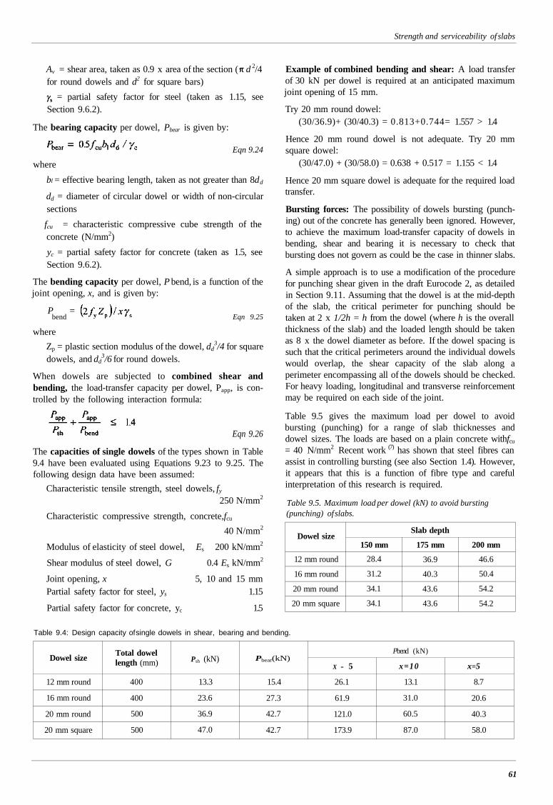
Strength and serviceability of slabs
Av = shear area, taken as 0.9 x area of the section ( d 2/4for round dowels and d2 for square bars)
= partial safety factor for steel (taken as 1.15, seeSection 9.6.2).
The bearing capacity per dowel, Pbear is given by:
Eqn 9.24
where
bl = effective bearing length, taken as not greater than 8dd
dd = diameter of circular dowel or width of non-circularsections
fcu = characteristic compressive cube strength of theconcrete (N/mm2)
yc = partial safety factor for concrete (taken as 1.5, seeSection 9.6.2).
The bending capacity per dowel, P bend, is a function of thejoint opening, x, and is given by:
P =bend Eqn 9.25
where
Zp = plastic section modulus of the dowel, dd3/4 for square
dowels, and dd3/6 for round dowels.
When dowels are subjected to combined shear andbending, the load-transfer capacity per dowel, Papp, is con-trolled by the following interaction formula:
Eqn 9.26
The capacities of single dowels of the types shown in Table9.4 have been evaluated using Equations 9.23 to 9.25. Thefollowing design data have been assumed:
Characteristic tensile strength, steel dowels, fy
250 N/mm2
Characteristic compressive strength, concrete,fcu
40 N/mm2
Modulus of elasticity of steel dowel, Es 200 kN/mm2
Shear modulus of steel dowel, G 0.4 Es kN/mm2
Joint opening, x 5, 10 and 15 mmPartial safety factor for steel, ys 1.15
Partial safety factor for concrete, yc 1.5
Table 9.4: Design capacity of single dowels in shear, bearing and bending.
Dowel size
12 mm round
16 mm round
20 mm round
20 mm square
Total dowellength (mm)
400
400
500
500
Psh (kN)
13.3
23.6
36.9
47.0
Pbear(kN)
15.4
27.3
42.7
42.7
Pbend (kN)
X = 5
26.1
61.9
121.0
173.9
x=10
13.1
31.0
60.5
87.0
x=5
8.7
20.6
40.3
58.0
61
Example of combined bending and shear: A load transferof 30 kN per dowel is required at an anticipated maximumjoint opening of 15 mm.
Try 20 mm round dowel:(30/36.9)+ (30/40.3) = 0.813+0.744= 1.557 > 1.4
Hence 20 mm round dowel is not adequate. Try 20 mmsquare dowel:
(30/47.0) + (30/58.0) = 0.638 + 0.517 = 1.155 < 1.4
Hence 20 mm square dowel is adequate for the required loadtransfer.
Bursting forces: The possibility of dowels bursting (punch-ing) out of the concrete has generally been ignored. However,to achieve the maximum load-transfer capacity of dowels inbending, shear and bearing it is necessary to check thatbursting does not govern as could be the case in thinner slabs.
A simple approach is to use a modification of the procedurefor punching shear given in the draft Eurocode 2, as detailedin Section 9.11. Assuming that the dowel is at the mid-depthof the slab, the critical perimeter for punching should betaken at 2 x 1/2h = h from the dowel (where h is the overallthickness of the slab) and the loaded length should be takenas 8 x the dowel diameter as before. If the dowel spacing issuch that the critical perimeters around the individual dowelswould overlap, the shear capacity of the slab along aperimeter encompassing all of the dowels should be checked.For heavy loading, longitudinal and transverse reinforcementmay be required on each side of the joint.
Table 9.5 gives the maximum load per dowel to avoidbursting (punching) for a range of slab thicknesses anddowel sizes. The loads are based on a plain concrete withfcu
= 40 N/mm2 Recent work (7) has shown that steel fibres canassist in controlling bursting (see also Section 1.4). However,it appears that this is a function of fibre type and carefulinterpretation of this research is required.
Table 9.5. Maximum load per dowel (kN) to avoid bursting(punching) of slabs.
Dowel size
12 mm round
16 mm round
20 mm round
20 mm square
Slab depth
150 mm
28.4
31.2
34.1
34.1
175 mm
36.9
40.3
43.6
43.6
200 mm
46.6
50.4
54.2
54.2
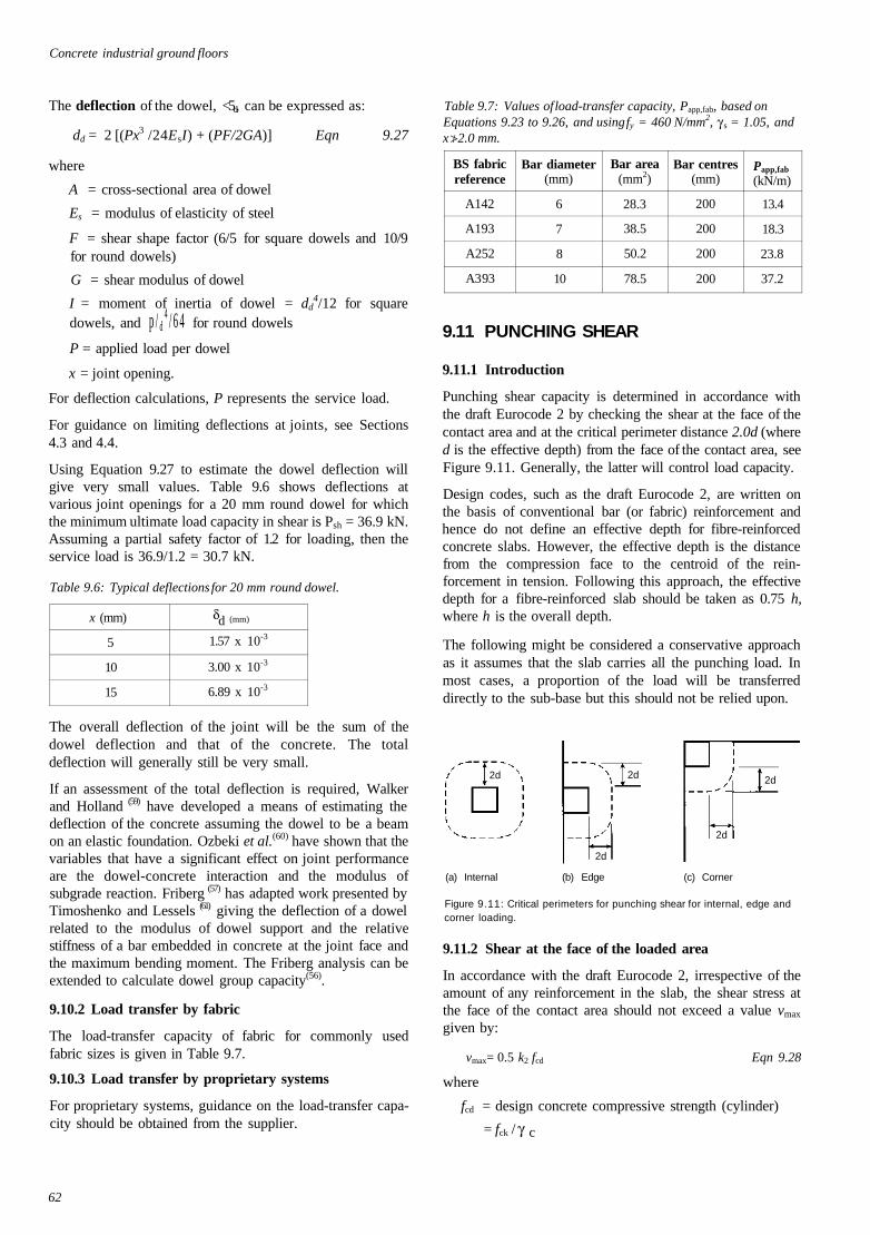
Concrete industrial ground floors
The deflection of the dowel, <5d, can be expressed as:
dd = 2 [(Px3 /24EsI) + (PF/2GA)] Eqn 9.27
where
A = cross-sectional area of dowel
Es = modulus of elasticity of steel
F = shear shape factor (6/5 for square dowels and 10/9for round dowels)
G = shear modulus of dowel
I = moment of inertia of dowel = dd4/12 for square
dowels, and p / d4 / 6 4 for round dowels
P = applied load per dowel
x = joint opening.
For deflection calculations, P represents the service load.
For guidance on limiting deflections at joints, see Sections4.3 and 4.4.
Using Equation 9.27 to estimate the dowel deflection willgive very small values. Table 9.6 shows deflections atvarious joint openings for a 20 mm round dowel for whichthe minimum ultimate load capacity in shear is Psh = 36.9 kN.Assuming a partial safety factor of 1.2 for loading, then theservice load is 36.9/1.2 = 30.7 kN.
Table 9.6: Typical deflections for 20 mm round dowel.
Table 9.7: Values of load-transfer capacity, Papp,fab, based onEquations 9.23 to 9.26, and using fy = 460 N/mm2, γ s = 1.05, andx (2.0 mm.
x (mm)
5
10
15
δd (mm)
1.57 x 10⁻³
3.00 x 10⁻³
6.89 x 10⁻³
The overall deflection of the joint will be the sum of thedowel deflection and that of the concrete. The totaldeflection will generally still be very small.
If an assessment of the total deflection is required, Walkerand Holland (59) have developed a means of estimating thedeflection of the concrete assuming the dowel to be a beamon an elastic foundation. Ozbeki et al.(60) have shown that thevariables that have a significant effect on joint performanceare the dowel-concrete interaction and the modulus ofsubgrade reaction. Friberg (57) has adapted work presented byTimoshenko and Lessels (61) giving the deflection of a dowelrelated to the modulus of dowel support and the relativestiffness of a bar embedded in concrete at the joint face andthe maximum bending moment. The Friberg analysis can beextended to calculate dowel group capacity(56).
9.10.2 Load transfer by fabric
The load-transfer capacity of fabric for commonly usedfabric sizes is given in Table 9.7.
9.10.3 Load transfer by proprietary systems
For proprietary systems, guidance on the load-transfer capa-city should be obtained from the supplier.
BS fabricreference
A142
A193
A252
A3 93
Bar diameter(mm)
6
7
8
10
Bar area(mm2)
28.3
38.5
50.2
78.5
Bar centres(mm)
200
200
200
200
Papp,fab
(kN/m)
13.4
18.3
23.8
37.2
9.11 PUNCHING SHEAR
9.11.1 Introduction
Punching shear capacity is determined in accordance withthe draft Eurocode 2 by checking the shear at the face of thecontact area and at the critical perimeter distance 2.0d (whered is the effective depth) from the face of the contact area, seeFigure 9.11. Generally, the latter will control load capacity.
Design codes, such as the draft Eurocode 2, are written onthe basis of conventional bar (or fabric) reinforcement andhence do not define an effective depth for fibre-reinforcedconcrete slabs. However, the effective depth is the distancefrom the compression face to the centroid of the rein-forcement in tension. Following this approach, the effectivedepth for a fibre-reinforced slab should be taken as 0.75 h,where h is the overall depth.
The following might be considered a conservative approachas it assumes that the slab carries all the punching load. Inmost cases, a proportion of the load will be transferreddirectly to the sub-base but this should not be relied upon.
2d
(a) Internal (b) Edge (c) Corner
Figure 9.11: Critical perimeters for punching shear for internal, edge andcorner loading.
9.11.2 Shear at the face of the loaded area
In accordance with the draft Eurocode 2, irrespective of theamount of any reinforcement in the slab, the shear stress atthe face of the contact area should not exceed a value vmax
given by:
vmax= 0.5 k2 fcd Eqn 9.28
where
fcd = design concrete compressive strength (cylinder)
= fck / γ c
62
2d
2d
2d
2d
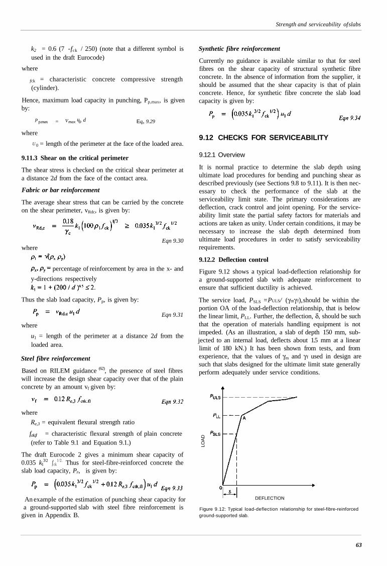
Strength and serviceability of slabs
k2 = 0.6 (7 -fck / 250) (note that a different symbol isused in the draft Eurocode)
where
fck = characteristic concrete compressive strength(cylinder).
Hence, maximum load capacity in punching, Pp,max, is givenby:
P p.max = Vmax uo d Eqn 9.29
where
U 0 = length of the perimeter at the face of the loaded area.
9.11.3 Shear on the critical perimeter
The shear stress is checked on the critical shear perimeter ata distance 2d from the face of the contact area.
Fabric or bar reinforcement
The average shear stress that can be carried by the concreteon the shear perimeter, vRdc, is given by:
Eqn 9.30where
percentage of reinforcement by area in the x- and
y-directions respectively
Thus the slab load capacity, Pp, is given by:
Eqn 9.31
where
u1 = length of the perimeter at a distance 2d from theloaded area.
Steel fibre reinforcement
Based on RILEM guidance (62), the presence of steel fibreswill increase the design shear capacity over that of the plainconcrete by an amount vf given by:
where
Re,3 = equivalent flexural strength ratio
fctk,fl = characteristic flexural strength of plain concrete(refer to Table 9.1 and Equation 9.1.)
The draft Eurocode 2 gives a minimum shear capacity of0.035 k1
3/2 f c k1 / 2 . Thus for steel-fibre-reinforced concrete the
slab load capacity, Pp, is given by:
An example of the estimation of punching shear capacity fora ground-supported slab with steel fibre reinforcement is
given in Appendix B.
Synthetic fibre reinforcement
Currently no guidance is available similar to that for steelfibres on the shear capacity of structural synthetic fibreconcrete. In the absence of information from the supplier, itshould be assumed that the shear capacity is that of plainconcrete. Hence, for synthetic fibre concrete the slab loadcapacity is given by:
9.12 CHECKS FOR SERVICEABILITY
9.12.1 Overview
It is normal practice to determine the slab depth usingultimate load procedures for bending and punching shear asdescribed previously (see Sections 9.8 to 9.11). It is then nec-essary to check the performance of the slab at theserviceability limit state. The primary considerations aredeflection, crack control and joint opening. For the service-ability limit state the partial safety factors for materials andactions are taken as unity. Under certain conditions, it may benecessary to increase the slab depth determined fromultimate load procedures in order to satisfy serviceabilityrequirements.
9.12.2 Deflection control
Figure 9.12 shows a typical load-deflection relationship fora ground-supported slab with adequate reinforcement toensure that sufficient ductility is achieved.
The service load, PSLS = PULS/ (γmγ f), should be within theportion OA of the load-deflection relationship, that is belowthe linear limit, PLL. Further, the deflection, δ, should be suchthat the operation of materials handling equipment is notimpeded. (As an illustration, a slab of depth 150 mm, sub-jected to an internal load, deflects about 1.5 mm at a linearlimit of 180 kN.) It has been shown from tests, and fromexperience, that the values of γm and γ f used in design aresuch that slabs designed for the ultimate limit state generallyperform adequately under service conditions.
LOA
D
DEFLECTION
Figure 9.12: Typical load-deflection relationship for steel-fibre-reinforcedground-supported slab.
63
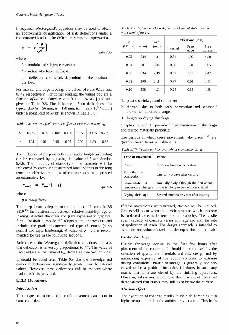
Concrete industrial ground floors
If required, Westergaard's equations may be used to obtainan approximate quantification of slab deflections under aconcentrated load P. The deflection 8 may be expressed as:
Eqn 9.35
where
k = modulus of subgrade reaction
l = radius of relative stiffness
c = deflection coefficient, depending on the position ofthe load.
For internal and edge loading, the values of c are 0.125 and0.442 respectively. For corner loading, the values of c are afunction of a/l, calculated as c = [1.1 - 1.24 (a/l)], and aregiven in Table 9.8. The influence of k on deflections of atypical slab (a = 56 mm, h = 150 mm, Ecm = 33 x 103 N/mm2)under a point load of 60 kN is shown in Table 9.9.
Table 9.8: Values of deflection coefficient c for corner loading.
a/l
c
0.050
1.04
0.075
1.01
0.100
0.98
0.125
0.95
0.150
0.92
0.175
0.89
0.200
0.86
The influence of creep on deflection under long-term loadingcan be estimated by adjusting the value of l, see Section9.4.6. The modulus of elasticity of the concrete will beinfluenced by creep under sustained load and thus in the longterm the effective modulus of concrete can be expressedapproximately by:
Eqn 9.36
where
= creep factor.
The creep factor is dependent on a number of factors. In BS8110 (l5) the relationships between relative humidity, age atloading, effective thickness and are expressed in graphicalform. The draft Eurocode 2(16)adopts a similar procedure andincludes the grade of concrete and type of cement (slow,normal and rapid hardening). A value of = 2.0 is recom-mended for use in the following sections.
Reference to the Westergaard deflection equations indicatesthat deflection is inversely proportional to kl2. The value ofl will reduce as the value of Ecm decreases. See Section 9.4.6.
It should be noted from Table 9.9 that the free-edge andcorner deflections are significantly greater than the internalvalues. However, these deflections will be reduced whereload transfer is provided.
9.12.3 Movements
Introduction
Three types of intrinsic (inherent) movement can occur inconcrete slabs:
Table 9.9: Influence of k on deflection of typical slab under apoint load of 60 kN.
k(N/mm3)
0.02
0.04
0.06
0.08
0.10
l(mm)
834
701
634
590
558
P/kl2
(mm)
4.31
3.05
2.49
2.15
1.93
Deflections (mm)
Internal
0.54
0.38
0.31
0.27
0.24
Freeedge
1.90
1.34
1.10
0.95
0.85
Freecorner
4.38
3.05
2.47
2.11
1.88
1. plastic shrinkage and settlement
2. thermal, due to both early contraction and seasonal/diurnal temperature changes
3. long-term drying shrinkage.
Chapters 10 and 11 provide further discussion of shrinkageand related materials properties.
The periods in which these movements take place (17.20) aregiven in broad terms in Table 9.10.
Table 9.10: Typical periods over which movements occur.
Type of movement
Plastic
Early thermalcontraction
Seasonal/diurnaltemperature changes
Drying shrinkage
Period
First few hours after casting
One to two days after casting
Annually/daily although the first annualcycle is likely to be the most critical
Several months or years after casting
If these movements are restrained, stresses will be induced.Cracks will occur when the tensile strain to which concreteis subjected exceeds its tensile strain capacity. The tensilestrain capacity of concrete varies with age and with the rateof application of strain. The design approach is intended toavoid the formation of cracks on the top surface of the slab.
Plastic shrinkage
Plastic shrinkage occurs in the first few hours afterplacement of the concrete. It should be minimised by theselection of appropriate materials and mix design and byminimising exposure of the young concrete to extremedrying conditions. Plastic shrinkage is generally not per-ceived to be a problem for industrial floors because anycracks that form are closed by the finishing operations.However, subsequent grinding or shot blasting of floors hasdemonstrated that cracks may still exist below the surface.
Thermal effects
The hydration of concrete results in the slab hardening at ahigher temperature than the ambient environment. This leads
64
Strength and serviceability of slabs
to an irreversible thermal contraction, which occurs fromaround 14 hours to one week after construction as the heatgenerated is lost to the environment. Temperature drops ofmore than 10°C are common during this period, resulting ina contraction strain of around 100 x 10-6
Reversible movements are also caused by the influence ofclimatic changes on industrial floors. The daily temperaturechanges are small and have little effect on industrial floors,as they are not exposed to direct sunlight. However, seasonaltemperature changes can cause significant movements. Asmany industrial floors are in unheated buildings, the annualchange can be greater than 15°C, corresponding to an unre-strained strain of around 150 x 10-6.
Long-term drying shrinkage
Long-term moisture loss from hardened concrete results indrying shrinkage. This process can last many years: it dependson the environment and the properties of the concrete. Afterbeing exposed to air for three months, the slab may haveundergone only 30% of its long-term drying shrinkage.Restraint can lead to the development of cracks. For a well-designed concrete, long-term shrinkage strains are in the range400 to 600 x 10-6 mm. For a 6 m slab these are equivalent toan overall unrestrained shortening of 2.4 to 3.6 mm, but thiswill be mitigated by restraint and creep: and it is estimated thatthe actual shortening will be approximately half these values.
A key factor influencing the drying shrinkage of concrete isthe water content. The more water that is available toevaporate from the concrete, the greater the tendency toshrink on drying. Long-term drying shrinkage can be min-imised by the selection of appropriate materials and mixdesign, see Section 10.3.2.
Shrinkage restraint stresses
If the slab is fully restrained, the shrinkage stress f sh, full can beexpressed as:
Eqn 9.37
whereE
cm = secant modulus of elasticity of the concrete
sh = long-term shrinkage strain.
As the shrinkage is time-dependent, it will be mitigated bycreep and so the value of Ecm, given in Table 9.1, should bemodified in line with Equation 9.37, taking = 2. Thus Ecm
is replaced by Ecm(t)= Ecm/3.
The factored shrinkage stress given by
Eqn 9.38
will give values that exceed the tensile capacity of plainconcrete and thus it is necessary to provide some means ofreducing shrinkage restraint. This is commonly achieved bymeans of a slip membrane separating the underside of theslab from the sub-base.
Coefficients of friction, for different slip media have beenevaluated by Timms(63) and vary from less than 1.0 to more
than 2.5. The conventional approach to evaluating theshrinkage restraint force is to assume it reaches a maximumvalue midway between free-movement joints. However, ithas been found that this tends to significantly over-estimatethe stresses. Table 3.3 in BS 8110-2 (l5) gives Values ofrestraint recorded in various structures. Although this is forearly thermal movements, the approach should be equallyvalid for shrinkage. For 'massive pour cast on to existingblinding' this recommends a restraint factor between 0.1 and0.2 (where full restraint is taken as 1.0).
For this report a restraint factor of 0.2 is recommended.Hence the estimated stress induced in the slab by the restraintto shrinkage,fsh is given by:
Eqn 9.39
Curling
Curling is the result of differential shrinkage between the topand bottom of the slab. Moisture loss from a slab is primarilyin one direction towards the surface, resulting in a moisturegradient that causes the slab to curl. It has not been currentUK practice to quantify curling-induced stresses. However,the bending stress,fcur, may be expressed as:
Eqn 9.40
where
Ecm(1) = modulus of elasticity of concrete modified due tocreep
v = Poisson's ratio (= 0.2)
= differential strain between the top and bottom of theslab, typically taken as (1.5 - 2.0) x 10-6 per mm of slabthickness.
The value of Ecm = 33 x 103 N/mm2 is modified to Ecm(t) bythe factor [1/(1 + ]. A creep factor of 2.0 is assumed,giving Ecm(t) = 11 x 103N/mm2.
Hence the estimated bending stress induced by curling,
Recommendations for dealing with restraint stresses
Recent research (8) has shown that shrinkage-induced stressesshould be considered in design, particularly when significanthogging moments occur due to imposed actions, such as uni-formly distributed loads (e.g. block stacking), see Section9.9.5. However, the interaction between the shrinkage-induced stresses and those due to loading is not wellunderstood. The relative magnitude of the former will be in-fluenced by environmental conditions and the time of loading.
65

Concrete industrial ground floors
Hence, in the absence of more detailed calculations, this calculating the hogging moment capacity in critical areas,report recommends that the net effect of the various The above conditions could also arise in areas of heavyrestrained strains may be taken as a flexural tensile stress of racking which may be additionally analysed as being1.5 N/mm2 and consideration should be given to deducting equivalent to block stacking.this from the flexural tensile strength of the concrete when
66
PART THREECONCRETE PERFORMANCE ANDCOMPONENT MATERIALSThe chapters in this Part consider the essential performance characteristics of concrete for floors and the commonmaterials used in such concrete. Reinforcement and the structural effect of reinforcements such as fibres, steel rein-forcement bar and steel fabric are not considered here, but in Chapter 7.
The principles of specifying, selecting, producing and using concrete in industrial floors are not fundamentally dif-ferent from those for concrete in numerous other applications. However, the requirements for concrete for floors arequite demanding, if construction is to be successful, and the floor is to meet its performance criteria, such asabrasion resistance, surface regularity and structural integrity. Satisfactory performance of floors is particularlydependent on adequate curing.
This Part will provide basic guidance for those responsible for specifying, producing and placing concrete for floors.
CONTENTS
10
10.110.210.310.410.510.6
CONCRETE PERFORMANCE
Specification considerations
Strength and related characteristics
Shrinkage
Mix design for placing and finishing
Abrasion resistance
Chemical resistance
11
11.111.2,1l-3
11.411:511.6
CONCRETE COMPONENTS
Cement
Aggregates
Admixtures
Dry shake-finishesSteel fibres
Synthetic fibres
10 CONCRETE PERFORMANCE
Note: At the time of publication of this report (2003), many BritishStandards for concrete and its constituent materials are beingdeveloped into European Standards, and many long-establishedStandards, whose reference numbers have become familiar, arebeing replaced. It is not possible to provide a comprehensive list ofall the changes that are expected, and so readers should ensure thatthey refer to the standards that are current at the time. Of particularimportance are the replacement of the main standard for concreteBS 5328 (64) by BS EN 206-1 (65) and BS 8500 (66), which is due to takeplace in December 2003, and of BS 8110, the code of practice forstructural concrete, by Eurocode 2; the date at which this willhappen is not known at present. In BS 8500, compressive strengthof concrete is specified by 'strength class' whereas BS 5328 uses theterm 'strength grade'. Otherwise, for practical purposes, there is nochange in the method of specifying cube strength.
10.1 SPECIFICATION CONSIDERATIONS
Concrete for floors should be designed for that specificpurpose. The mix design considerations will need to addressthe performance objectives described in this chapter. It maybe necessary to make compromises to take into accountpotentially opposing performance objectives. For example,increasing strength through the use of higher cement contentmay have the potentially undesirable effect of increasingshrinkage.
The overall objective is to produce concrete of adequate per-formance using local materials where possible. The importantperformance factors to be considered are:
strength and related characteristics
placing and finishing needs
shrinkage
durability
- against abrasion
- against chemicals.
Chapter 11 considers the characteristics of the constituentmaterials that are needed to meet these performance aspects.
10.2 STRENGTH AND RELATEDCHARACTERISTICS
10.2.1 Compressive and flexural strength
The standard method of specifying concrete for moststructural applications is by characteristic cube strength.However, the important strength parameter for ground-supported slabs is flexural tensile strength.
Flexural tensile testing of concrete is not common and in thedraft Eurocode 2 (16) fixed relationships, based on empiricaldata, are used to calculate flexural tensile strength. SeeSection 9.4.1, Table 9.1 and Equation 9.1. Any departurefrom these relationships and the data given would requiretest data to establish the flexural tensile strength of aproposed concrete mix.
10.2.2 Ductility of fibre-reinforced concrete
Steel fibres are commonly used in concrete for industrial floorsand the resultant composite concrete can have considerableductility, often termed 'toughness'. Ductility is dependent onfibre type, dosage, tensile strength and anchorage mechanism.It should be pointed out that steel fibres, used at practicaldosages, will not increase post-first-crack flexural strength.
Structural synthetic fibres have been developed that can alsoenhance ductility (47). These fibres are significantly largerthan the monofilament and fibrillated polypropylene fibres incommon use and are used at much higher dosages. As withsteel fibres, data should be sought from suppliers on the per-formance of such fibres in practice.
Information on testing for ductility characteristics can befound in Chapter 7.
10.2.3 Maturity of concrete in cold store floors
Concrete floors are used in cold stores with temperatures aslow as -40°C. Fully matured concrete performs well atconstant low temperatures. Immature concrete with a com-pressive strength of less than 5 N/mm2 may be damaged byfreezing and immature concrete with strength higher than5 N/mm2 may have its strength development curtailed by tooearly a reduction in temperature. It is therefore essential thatcold store slabs are allowed to mature for at least 28 days orthat other steps are taken to ensure adequate in-situ strength,before the temperature is drawn down.
Concrete not subject to wetting will resist both continuedexposure to temperatures below freezing and freeze-thawcycles. Therefore there is generally no need to considerenhanced performance.
10.3 SHRINKAGE
10.3.1 Introduction
Shrinkage is a reduction in size or volume; for concretefloors, several generic types of shrinkage are of concern. Inorder of decreasing importance, they are:
• drying shrinkage
Previous pageis blank
69
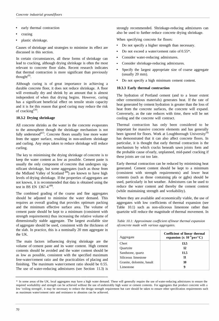
Concrete industrial ground floors
early thermal contraction
crazing
plastic shrinkage.
Causes of shrinkage and strategies to minimise its effect arediscussed in this section.
In certain circumstances, all these forms of shrinkage canlead to cracking, although drying shrinkage is often the mostrelevant to concrete floor slabs. Recent research indicatesthat thermal contraction is more significant than previouslythought(8).
Although curing is of great importance in achieving adurable concrete floor, it does not reduce shrinkage. A floorwill eventually dry and shrink by an amount that is almostindependent of when that drying begins. However, curinghas a significant beneficial effect on tensile strain capacityand it is for this reason that good curing may reduce the riskof cracking(20).
10.3.2 Drying shrinkage
All concrete shrinks as the water in the concrete evaporatesto the atmosphere though the shrinkage mechanism is notfully understood(67). Concrete floors usually lose more waterfrom the upper surface, resulting in non-uniform shrinkageand curling. Any steps taken to reduce shrinkage will reducecurling.
The key to minimising the drying shrinkage of concrete is tokeep the water content as low as possible. Cement paste isusually the only component of concrete that undergoes sig-nificant shrinkage, but some aggregates (such as those fromthe Midland Valley of Scotland (68)) are known to have highlevels of drying shrinkage. If the properties of aggregates arenot known, it is recommended that data is obtained using thetest in BS EN 1367-4 (69).
The combined grading of the coarse and fine aggregatesshould be adjusted to minimise the water demand. Thisrequires an overall grading that provides optimum packingand the minimum effective surface area. The volume ofcement paste should be kept to a minimum (consistent withstrength requirements) thus increasing the relative volume ofdimensionally stable aggregate. The largest available sizeof aggregate should be used, consistent with the thickness ofthe slab. In practice, this is a nominally 20 mm aggregate inthe UK.
The main factors influencing drying shrinkage are thevolume of cement paste and its water content. High cementcontents should be avoided and the water content should beas low as possible, consistent with the specified maximumfree-water/cement ratio and the practicalities of placing andfinishing. The maximum water/cement ratio should be 0.55.The use of water-reducing admixtures (see Section 11.3) is
strongly recommended. Shrinkage-reducing admixtures canalso be used to further reduce concrete drying shrinkage.
When specifying concrete for floors:
Do not specify a higher strength than necessary.
Do not exceed a water/cement ratio of 0.55*.
Consider water-reducing admixtures.
Consider shrinkage-reducing admixtures.
Specify the largest appropriate size of coarse aggregate(usually 20 mm).
Do not specify a high minimum cement content.
10.3.3 Early thermal contraction
The hydration of Portland cement (and to a lesser extentother cementitious materials) generates heat. If the rate ofheat generated by cement hydration is greater than the loss ofheat from the concrete surfaces, the concrete will expand.Conversely, as the rate reduces with time, there will be netcooling and the concrete will contract.
Thermal contraction has only been considered to beimportant for massive concrete elements and has generallybeen ignored for floors. Work at Loughborough University(8)
has demonstrated that it can also affect concrete floors. Inparticular, it is thought that early thermal contraction is themechanism by which cracks beneath sawn joints form andthe probable cause of early, unplanned, mid-panel cracking ifthese joints are cut too late.
Early thermal contraction can be reduced by minimising heatgenerated. Cement content should be kept to a minimum(consistent with strength requirements) and lower heatcements (such as those containing pfa or ggbs) should beused, particularly in hot weather. Admixtures can be used toreduce the water content and thereby the cement content(while maintaining strength and workability).
Where they are available and economically viable, the use ofaggregates with low coefficients of thermal expansion (seeTable 10.1) such as non-siliceous limestone rather thanquartzite will reduce the magnitude of thermal movement. In
Table 10.1: Approximate coefficient of linear thermal expansionof concrete made with various aggregates.
Aggregate
ChertQuartziteSandstone, quartzSiliceous limestoneGranite, dolomite, basaltLimestone
Coefficient of linear thermalexpansion (x l0 -6per°C)
13.512
11.511109
* In some areas of the UK, local aggregates may have a high water demand. These will generally require the use of water-reducing admixtures to ensure therequired workability and strength can be achieved without the use of undesirably high water or cement contents. For aggregates that produce concrete with alow 'ceiling strength', it may be necessary to reduce the design strength requirement but care should be taken to ensure other specification requirements suchas maximum water/cement ratio and resistance to abrasion can be achieved.
70
Concrete performance
many cases, this will also increase the strain capacity of theconcrete, thus increasing its resistance to cracking (7O-7I).
In hot weather, consideration should be given to producingand placing concrete in the coolest part of the day and whenconcrete materials are at their coolest.
10.3.4 Crazing
Crazing is the result of differential shrinkage of the surfacezone of a concrete slab relative to the bulk and is a commonfeature of power-finished floors. The topic is discussed inSection 5.6. Experience suggests that, despite its appearance,crazing generally has no effect on the performance of a floorsurface.
10.3.5 Plastic shrinkage
As the name implies, plastic shrinkage occurs whilst theconcrete is still plastic, i.e. before it hardens. The main causeof plastic shrinkage is rapid drying of the exposed concretesurface. If the rate of evaporation from the surface exceedsthe rate at which bleed water rises to the surface, netshrinkage will occur (with the possibility of subsequentcracking).
As the main cause of plastic shrinkage is rapid drying of theconcrete surface, materials and mix design normally have alimited influence. However, highly cohesive concretes withvery low bleed characteristics are particularly susceptible toplastic shrinkage cracking. Concretes with low water/cementratios or containing fine additions such as silica fume ormetakaolin may be at higher risk, particularly if early pro-tection is inadequate.
Loss of moisture from the surface can be reduced by pro-tecting the surface from drying air flows, particularly inwarm weather. Protection from wind and sun is essential andfloors should be constructed after the walls and roof are inposition and openings are sealed. See Chapter 12.
The use of set-retarding admixtures will extend the timeduring which the concrete is susceptible to plastic shrinkage.
Curing is the aspect of floor construction that has the greatestinfluence over plastic shrinkage (and associated plasticcracking). Effective early curing limits evaporation from theconcrete surface during the early stages of setting andhardening, when the tensile strain capacity of the concrete islow. However, there are often practical difficulties in applyingcuring measures early enough to prevent plastic shrinkagecracking completely.
Power finishing usually closes up plastic cracks although notnecessarily to full depth.
10.4 MIX DESIGN FOR PLACING ANDFINISHING
Concrete for floors must be workable enough to suit themethod of laying. In BS EN 206-1 (65) and BS 8500(66), work-ability is termed 'consistence', although the term workabilityis still recognised and is used here. Workability can be
measured by several established methods, including slumpand flow table spread. Slump should be measured inaccordance with BS EN 12350-2 (72). For manually placedconcrete a minimum slump of 75 mm (slump class S2) is rec-ommended, while for mechanically placed concrete a targetslump of up to 150 mm (slump class S3) is typical. There isno practical benefit in specifying a higher slump.
Mix design should aim to create a homogenous and mod-erately cohesive concrete that will not segregate when beingcompacted and finished. Excessively cohesive concrete canbe difficult to place, compact and finish. Excessive bleedingshould be avoided but some limited bleed water is required toassist with the formation of a surface mortar layer that can belevelled and closed by the power-finishing process. Wheredry shake finishes are used, sufficient water is required at thesurface for hydration of the cement component of thematerial.
Aggregate content should be maximised by using an overallaggregate grading that provides the optimum packing and theminimum effective surface area. In practice, there may belimitations on the aggregate gradings available, see Section11.2. However, it is important to have consistent gradings.
Where a dry shake finish is to be used, fine aggregatecontents of the base concrete may be reduced marginally asthe dry shake will provide the closed finish. This may bebeneficial in increasing workability for a given watercontent.
High cement content concretes (above 400 kg/m3) are likelyto be excessively cohesive and may lead to power-finishingproblems particularly in warm weather.
Allowance should be made for fibres. Steel fibres and syn-thetic structural fibres will reduce workability by about25 mm. The specified workability should take account ofthis, particularly when the steel fibres are to be added on site.
Admixtures are useful in increasing workability for a givenwater content and either shortening or lengthening work-ability retention times, see Section 11.3.
After batching, the designed workability can reduce as aresult of absorption by the aggregates and by evaporation.Delays in the arrival of ready-mixed concrete trucks andwarm weather will both increase these effects. A practicalway of dealing with this is for the concrete producer and con-tractor to make provision for the workability to be adjustedunder controlled conditions on site. Water additions shouldbe supervised by a competent technician and should belimited to that required to increase the workability to thatoriginally specified. The procedure should ensure that themaximum specified water/cement ratio or the water/cementratio required for the specified strength, whichever is thecontrolling value, is not exceeded. When water is added onsite, the concrete should be adequately re-mixed. Site recordsof water additions and final workability should be kept.
The processes for finishing concrete floors (floating, trow-elling, etc.) are particularly susceptible to changes in
71
Concrete industrial ground floors
workability and setting characteristics of concrete. Therefore,avoiding variability in these aspects of performance should bea high priority. For successful laying and finishing of floorslabs it is essential that concrete is well mixed and that work-ability is consistent within and between batches. Variations inproperties of adjacent areas of concrete can cause problems inmaintaining the working face and avoiding cold joints.Adjacent areas of concrete at differing stages of stiffening andhardening lead to problems with levels and the smearing ofwet mortar paste over hardened areas.
10.5 ABRASION RESISTANCE
Achieving adequate abrasion resistance of a concrete floordepends primarily on effective use of power trowels on theconcrete as it sets and, to a lesser extent, on the fineaggregate and cement used in the concrete. Fine aggregate inthe surface zone can be either present in the bulk concreteused for the floor or a constituent of a dry shake finishapplied to the surface.
The finishing process, in particular the power trowelling, is askilled activity that should take into account the ambientconditions. Achieving appropriate abrasion resistance andother surface characteristics requires careful timing andcontrol. Although power trowelling, and in particularrepeated power trowelling, is a significant factor in dev-eloping abrasion resistance, excessive repetitions of theprocess do not necessarily further enhance performance andcan adversely affect the appearance.
The surface of most industrial floors will remain durable forthe life of the installation. The coarse aggregate will not beexposed by normal wear and consequently does not con-tribute to the performance of the surface. In floors subject toextreme wear such as in metal working, and where the floorsurface is expected to be worn away, the coarse aggregatemay be more important, see Section 11.2.
Fine aggregate will be present in a floor surface and so shouldnot include any soft, friable materials, see Section 11.2.
To improve abrasion resistance of direct finished concrete,BS 8204-2: 2002 (l0) recommends the use of higher minimumcement contents and strength classes. For floors in distri-bution and warehouse facilities, where power-finishing is thenorm, a lower cement content is considered desirable toreduce shrinkage. BS 8204-2 (l0) covers a wide range ofwearing surfaces and construction practice and so adopts amore conservative approach. Current thinking places greatersignificance on the role of water/cement ratio (73) on the per-formance of concrete in general and identifies that there areupper limits on cement content, beyond which performanceis not increased. This has also been confirmed with specificreference to power-finished floors where the finishingprocess 'densities' and reduces the effective water/cementratio of the surface zone of the concrete (9,74). This approachis adopted in BS 8500(66), in which designated concretes havethe same strength classes and water/cement ratios as in BS5328 but lower minimum cement contents.
Cement contents above about 360 kg/m3 are unlikely toimprove the abrasion resistance of power-finished floors. Itis, however, very important to ensure that water/cementratios do not exceed 0.55. A typical concrete for flooring ofcompressive strength class C28/35 (grade C35) or C32/40(grade C40), with water/cement ratio of 0.55 and minimumcement content of 325 kg/m3, will have adequate abrasionresistance in most power-trowel led floors, provided certainrestrictions on the fine aggregate are observed (see Section11.2), and the concrete is adequately cured.
Where enhanced abrasion resistance is required, the use of dryshake finishes can be considered, see Section 11.4. These canbe beneficial because they may have an optimally gradedaggregate or because metallic aggregates are used or both.However, aggregates used in some dry shake finishes may giveno better performance than the aggregate in the base concrete.
Effective curing is very important in creating abrasionresistance. This is typically done by spraying resin-basedcuring compounds on the surface as soon as practicable afterthe finishing process. During the finishing process it isimportant to minimise surface drying. One of the key factorsaffecting drying is air movement across the concrete surfaceand therefore buildings should be totally enclosed before thefloor is constructed. See Chapter 12.
The factors affecting abrasion resistance are summarised inTable 10.2. It is not considered appropriate to give pre-scriptive advice on achieving the performance classes in BS8204-2, see Table 5.1. Specialist flooring contractors andmaterial suppliers should be consulted for advice.
Abrasion resistance develops over time, so even if a floor hasgained enough strength to allow it to be loaded, it may nothave developed adequate abrasion resistance. This should beconsidered where construction programmes are very short,see Section 12.3.
Testing for abrasion resistance
A test method for assessing the abrasion resistance of floorsis described in BS 8204-2: 2002(l0).
Problems of inadequate abrasion resistance are not commonand experience suggests that floors do not need to be, and inpractice are not, routinely tested for compliance. If a floor isto be tested, it should be noted that resin-based curing com-pounds create a layer or 'skin' on the surface that can beimpenetrable to the abrasion test machine and can cause mis-leading results (75).
Some curing compounds are also described as surfacehardeners or surface-penetrating sealers and may have long-term effects on the abrasion resistance of concrete. Similarproducts are used to improve floors with inadequate abrasionresistance.
10.6 CHEMICAL RESISTANCE
Any agent that attacks hydrated cement will ultimatelydamage a concrete floor surface if it stays in contact with the
72
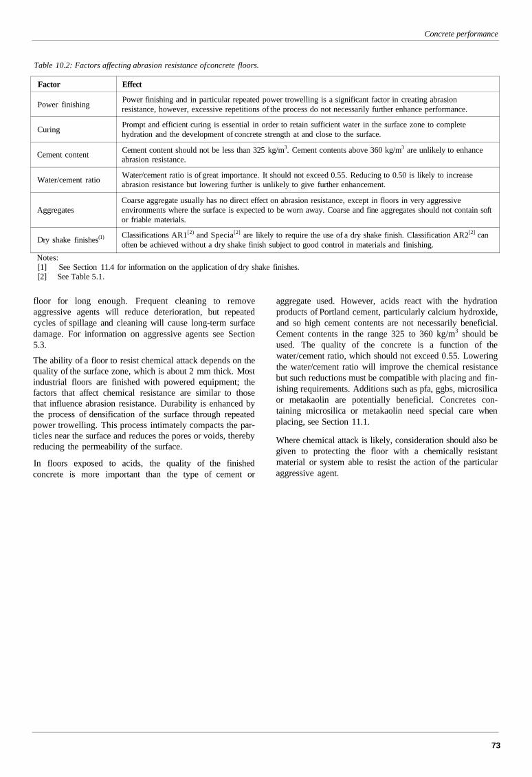
Concrete performance
Table 10.2: Factors affecting abrasion resistance of concrete floors.
Factor
Power finishing
Curing
Cement content
Water/cement ratio
Aggregates
Dry shake finishes(1)
Effect
Power finishing and in particular repeated power trowelling is a significant factor in creating abrasionresistance, however, excessive repetitions of the process do not necessarily further enhance performance.
Prompt and efficient curing is essential in order to retain sufficient water in the surface zone to completehydration and the development of concrete strength at and close to the surface.
Cement content should not be less than 325 kg/m3. Cement contents above 360 kg/m3 are unlikely to enhanceabrasion resistance.
Water/cement ratio is of great importance. It should not exceed 0.55. Reducing to 0.50 is likely to increaseabrasion resistance but lowering further is unlikely to give further enhancement.
Coarse aggregate usually has no direct effect on abrasion resistance, except in floors in very aggressiveenvironments where the surface is expected to be worn away. Coarse and fine aggregates should not contain softor friable materials.
Classifications AR1[2) and Specia[2] are likely to require the use of a dry shake finish. Classification AR2[2] canoften be achieved without a dry shake finish subject to good control in materials and finishing.
Notes:[1] See Section 11.4 for information on the application of dry shake finishes.[2] See Table 5.1.
floor for long enough. Frequent cleaning to removeaggressive agents will reduce deterioration, but repeatedcycles of spillage and cleaning will cause long-term surfacedamage. For information on aggressive agents see Section5.3.
The ability of a floor to resist chemical attack depends on thequality of the surface zone, which is about 2 mm thick. Mostindustrial floors are finished with powered equipment; thefactors that affect chemical resistance are similar to thosethat influence abrasion resistance. Durability is enhanced bythe process of densification of the surface through repeatedpower trowelling. This process intimately compacts the par-ticles near the surface and reduces the pores or voids, therebyreducing the permeability of the surface.
In floors exposed to acids, the quality of the finishedconcrete is more important than the type of cement or
aggregate used. However, acids react with the hydrationproducts of Portland cement, particularly calcium hydroxide,and so high cement contents are not necessarily beneficial.Cement contents in the range 325 to 360 kg/m3 should beused. The quality of the concrete is a function of thewater/cement ratio, which should not exceed 0.55. Loweringthe water/cement ratio will improve the chemical resistancebut such reductions must be compatible with placing and fin-ishing requirements. Additions such as pfa, ggbs, microsilicaor metakaolin are potentially beneficial. Concretes con-taining microsilica or metakaolin need special care whenplacing, see Section 11.1.
Where chemical attack is likely, consideration should also begiven to protecting the floor with a chemically resistantmaterial or system able to resist the action of the particularaggressive agent.
73
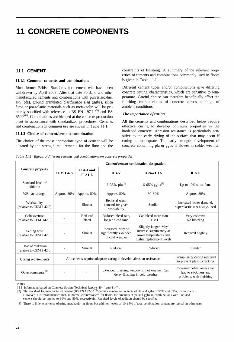
11 CONCRETE COMPONENTS
11.1 CEMENT
11.1.1 Common cements and combinations
Most former British Standards for cement will have beenwithdrawn by April 2003. After that date Portland and othermanufactured cements and combinations with pulverised-fuelash (pfa), ground granulated blastfurnace slag (ggbs), silicafume or pozzolanic materials such as metakaolin will be pri-marily specified with reference to BS EN 197-1 (76) and BS8500(66). Combinations are blended at the concrete productionplant in accordance with standardized procedures. Cementsand combinations in common use are shown in Table 11.1.
11.1.2 Choice of cement/cement combination
The choice of the most appropriate type of cement will bedictated by the strength requirements for the floor and the
constraints of finishing. A summary of the relevant prop-erties of cements and combinations commonly used in floorsis given in Table 11.1.
Different cement types and/or combinations give differingconcrete setting characteristics, which are sensitive to tem-perature. Careful choice can therefore beneficially affect thefinishing characteristics of concrete across a range ofambient conditions.
The importance of curing
All the cements and combinations described below requireeffective curing to develop optimum properties in thehardened concrete. Abrasion resistance is particularly sen-sitive to the early drying of the surface that may occur ifcuring is inadequate. The early strength development ofconcrete containing pfa or ggbs is slower in colder weather,
Table 11.1: Effects of different cements and combinations on concrete properties[1].
Concrete property
Standard level ofaddition
7/28 day strength
Workability(relative to CEM I 42.5)
Cohesiveness(relative to CEM 142.5)
Setting time(relative to CEM I 42.5)
Heat of hydration(relative to CEM I 42.5)
Curing requirements
Other comments [3]
Cement/cement combination designation
CEM I 42.5
-
Approx. 80%
-
-
-
-
II A-LandII ALL
Approx. 80%
Similar
Reducedbleed
Similar
Similar
IIB-V
6-35% pfa[2]
Approx. 80%
Reduced waterdemand for given
workability
Reduced bleed rate,longer bleed time
Increased. May besignificantly extended
in cold weather
Reduced
II -SorIIIA
6-65% ggbs[2]
60-80%
Similar
Can bleed more thanCEM1
Slightly longer. Mayincrease significantly atlower temperatures and
higher replacement levels
Reduced
All cements require adequate curing to develop abrasion resistance.
- - Extended finishing window in hot weather. Candelay finishing in cold weather
II A D
Up to 10% silica fume
Approx. 80%
Increased water demand,superplasticisers always used
Very cohesiveNo bleeding
Reduced slightly
Similar
Prompt early curing requiredto prevent plastic cracking
Increased cohesiveness canlead to stickiness and
problems with finishing
Notes[ I ] Information based on Concrete Society Technical Reports 40 (77) and 41 (78).[2] The standard for manufactured cement (BS EN 197-1)(76) permits maximum contents of pfa and ggbs of 35% and 65%, respectively.
However, it is recommended that, in normal circumstances for floors, the amounts of pfa and ggbs in combinations with Portlandcement should be limited to 30% and 50%, respectively. Required levels of addition should be specified.
[3] There is little experience of using metakaolin in floors but addition levels of 10-15% of total combination content are typical in other uses.
74
so proper curing is important to prevent moisture loss, whichmay result in surface dusting and poorer abrasion resistance.It is therefore important to apply appropriate curing tech-niques as soon as practical after finishing is completed.
11.1.3 Expansive cements
Expansive cements have been used in the USA for someyears - see ACI 223 (79). These are based on calcium sulfo-aluminates which, when blended with Portland cement and asource of sulfate (usually ground anhydrite), hydrate to formexpansive calcium sulfo-aluminate hydrates (i.e. ettringite).These types of cement are not covered by British orEuropean standards but are described in ASTM C845-96 (80).Thorough understanding is needed of these specialistmaterials before their use can be considered. Referenceshould be made to ACI 223, and manufacturers of expansivecements consulted for further information.
11.2 AGGREGATES
11.2.1 Introduction
Aggregates comprise typically 70% of the volume ofconcrete. For environmental and economic reasons, localaggregates should be used where possible. Aggregates foruse in concrete floors should conform to BS 882 (8I) and BSEN 12620 (82). Recycled aggregates should only be used withextreme care as levels of low-density materials and im-purities may be unacceptable.
Fine aggregate (sand) gradings should comform to grades C,M or F of Table 4 of BS 882: 1992 (8I). Fine aggregates withgradings at the coarse end of grade C or the fine end of gradeF should be avoided. If crushed rock sand is used, either onits own or in combination with other sands, the proportion ofthe combined sand by mass passing the 75 m sieve shouldnot exceed 9%. See Table 6 of BS 882 and BS EN 12620:2002 (82).
Aggregates should be free from impurities such as lignitethat may affect the integrity or appearance of the finishedsurface of a floor. It may not be possible to eliminate impu-rities entirely but if there are concerns about potentialimpurities in an aggregate source, the contractor should seekassurances from the concrete producer about proceduresadopted to minimise this risk. Information on the history ofuse of sources should be sought. Information on dealing withsurface defects can be found in Chapter 5. See also Ref. 23.
11.2.2 Mechanical performance
Abrasion resistance
In most floors, coarse aggregates have no direct influence onthe abrasion resistance of the surface, and so all normal con-creting aggregates are suitable. For floors in exceptionallyaggressive environments where the surface of the floor islikely to be worn away, the mechanical properties of thecoarse aggregate are important and the 10% fines valueshould not be less than 150 kN.
BS EN 12620 (82), which will be adopted from December2003, has adopted a classification system based on the LosAngeles test. There is no direct correlation between this testand the 10% fines test. A maximum Los Angeles coefficientof 40 is recommended for aggregate for normal floors. Forfloors in exceptionally aggressive environments, it may beappropriate to specify a lower value of 30 or 35.
Fine aggregates are present at the surface and can affect per-formance. Fine aggregates that contain larger particles offriable materials that are likely to break down undermechanical action should not be used.
Abrasion resistance may be enhanced by the use of dry shakefinishes (see Sections 10.5 and 11.4).
Slip resistance
Most floors are finished by power trowelling to create adense smooth surface. Therefore, under normal circum-stances, the aggregates used have negligible effect on the slipresistance of the floor. See Section 5.9.
11.2.3 Drying shrinkage of aggregates
The principal effect of the aggregate is to restrain the con-traction of the cement paste, thereby helping to reduce thelikelihood of cracking. In general, aggregates with a highermodulus of elasticity (greater 'stiffness') and rough particlesurface textures are likely to offer more restraint to concreteshrinkage.
The magnitude of shrinkage can vary substantially with typeof aggregate. Quartz, granite and limestone are frequentlyassociated with low concrete shrinkage, whereas sandstoneand some basic igneous rock aggregates are more likely tocause or permit comparatively higher shrinkage.
Some aggregates notably but not confined to areas ofScotland have high shrinkage values, see BRE Digest 357 (68).The drying shrinkage associated with aggregates should notexceed 0.075% when tested to BS EN 1367-4 (69).
11.3 ADMIXTURES
11.3.1 Introduction
Admixtures can have substantial benefits for concrete forindustrial floors in the following ways. They can:
• reduce the free water content while maintaining work-ability
• increase workability for rapid placement and compaction
• control setting to allow earlier finishing
• make finishing easier
• reduce drying shrinkage.
Careful selection is essential to obtain a satisfactory result.All admixtures should be used strictly in accordance with themanufacturers instructions. Incorrect use and inadequatemixing can lead to variable setting characteristics and poorperformance.
Concrete components
75
Concrete industrial ground floors
The main benefits and limitations on the use of variousadmixtures are outlined below. Concrete Society TechnicalReport 18, Guide to the selection of admixtures for concrete(83),is a useful reference.
11.3.2 High-range water-reducing admixtures
High-range water-reducing admixtures (HRWRA) are typ-ically dosed at 0.30 to 1.5 litres per 100 kg of cement andgive water reductions of up to 30% without reducing work-ability. Performance depends on several factors includingadmixture type and dose. High-range water reducers havegreater disper-sing power than normal plasticisers for anequivalent dosage.
Shrinkage of concrete occurs mainly in the cement paste andso to limit shrinkage, not only the water but also the cementcontent should be kept as low as possible. The large waterreduction potentially available using a high-range water-reducing admixture should also allow cement content to bereduced while still achieving the required strength class.
For a given mix design, a high-range water reducer can beused to reduce the water content or cement content, toincrease the workability, or a combination of these. Carefulselection of a specific HRWRA helps to achieve a range ofperformance objectives such as retaining workability andstiffening characteristics at different ambient temperatures.Performance may depend on the type of cement used.
Some HRWRAs contain finishing aids. They are designed towork at the interface between the concrete surface and thepower-finishing equipment to provide lubrication.
11.3.3 Normal water-reducing admixtures and retardingadmixtures
Workability retention is usually more critical than retardationof setting. The use of a higher dosage of a slightly retardingwater-reducing admixture to remove some water but also toincrease initial workability will often be a better way ofachieving the desired result.
Although normal water-reducing admixtures can be usedsuccessfully in concrete for floors, they should be used withparticular care because of their relatively lower performanceand tendency to cause retardation. Advice based on ex-perience of their use in floors should be sought beforespecifying them or accepting a concrete that contains theseproducts.
Careful attention to mix design and to mixing is essential ifthe concrete is to have uniform workability, cohesion andsetting characteristics. This is particularly important whenthese water-reducing admixtures are used, as the low dosemakes them difficult to disperse uniformly through the mix.Failure to mix thoroughly will cause variations betweenloads and within loads, which will result in 'soft' patches inthe floors surrounded by concrete that has undergone initialset. Mortar paste may then be smeared across the set areasduring finishing, causing problems with tolerances and withdelamination of the surface and with appearance.
11.3.4 Accelerating admixtures
Most set accelerators are based on calcium nitrate. They maybe useful in cold weather to reduce setting times and to avoiddelays in the start of the finishing operations.
Calcium-chloride-based accelerators should not be used inslabs with any steel, including fibres, embedded in the con-crete.
11.3.5 Shrinkage-reducing admixtures
Shrinkage-reducing admixtures are non-aqueous liquids thatalter the mechanism of drying shrinkage in a way that reducesthe internal stresses that lead to the formation of cracks.Reductions in shrinkage in the range 25-50% have beenobserved (8). Dosage is normally 5-7 litres/m3, and althoughthis type of admixture is not water-based, the concrete mixwater should be reduced by an amount equivalent to theadmixture dose. Shrinkage-reducing admixtures can be usedwith other admixtures providing they are added separately. Itis recommended that specialist advice is sought. They gen-erally perform better when used with a high-rangewater-reducing admixture used to reduce total free water.
11.3.6 Air-entraining admixtures
Air entrainment is normally used to resist damage to exposedsaturated concrete by freeze-thaw action and is therefore notapplicable to most industrial floors. In cold stores theconcrete is not saturated and the number of freeze-thawcycles is very small, so air entrainment is not needed.Entrained air can cause problems with power-finishedconcrete floors, including delamination.
11.3.7 Concrete production with admixtures
To ensure uniform workability and setting across the slabwhen admixtures are used, it is particularly important that theorder and timing of the concrete batching sequence is con-sistent. It is essential that flooring concrete is uniformly andconsistently mixed and that admixtures do not come intodirect contact with dry cement. Ideally, all components of theconcrete should be mixed at the batching plant. If it is con-sidered necessary to add materials at site, quality controlprocedures should include:
• procedures and records for the calibration and main-tenance of dosing equipment, uniformity of dosingprocedure, dosage rates, and re-mixing time
• procedures for recording the addition of admixtures,water or other materials including the time of addition,workability before and after addition, quantity ofadmixture or water added, additional mixing given.
This topic is discussed fully in Concrete Society TechnicalReport 18(83).
11.4 DRY SHAKE FINISHES
Dry shake finishes are dry blends of cements, fineaggregates, admixtures and sometimes pigments. They are
76
Concrete components
usually factory blended and supplied in bags. They are usedfor one or more of the following reasons:
• to enhance abrasion resistance
• to provide colour
• to help suppress steel fibres at the surface.
Dry shake finishes depend upon bleed water from theunderlying concrete for hydration and for them to be workedmonolithically into the base concrete. The take-up of waterby the dry shake lowers the water/cement ratio, improvingthe quality of the near-surface concrete. Although excessbleed water should be avoided by appropriate mix design, itis equally important to have enough moisture at the surfacewhen dry shake materials are applied.
Any enhancement in abrasion resistance over a directfinished concrete floor depends on the constituents andwater/cement ratio of the base concrete, and the selected dryshake material and construction practice. When consideringthe use of dry shakes to enhance abrasion resistance, Section10.5 should be studied carefully. In addition, the suppliershould be able to demonstrate long-term performance.
When a coloured floor is required, the appearance of smalllaboratory-produced samples may not be representative ofthe finished floor. The colour of a concrete floor with acoloured dry shake finish is likely to be more variable than aresin coating or other applied coatings such as paint, seeSection 5.4. Where appearance is important, advice on pro-tecting new floors is given in Section 12.5.
For introductory guidance on the practical application of dryshake finishes, see Ref. 84.
11.5 STEEL FIBRES
The performance of steel fibres in relation to ductility is dis-cussed in Section 7.4. The purpose of this section is todiscuss steel fibres as they affect concrete mix design.
Mix design for steel fibre concrete
Depending on the overall grading of the available aggregatesand the volume and type of steel fibre used, it may be nec-essary to increase fine aggregate content to improve fibredispersion and to make the concrete easier to compact andfinish. Increases in fines content will increase water demand.The fibres themselves will also have some effect on worka-bility. High-range water-reducing admixtures are commonlyused in steel-fibre-reinforced concrete.
Typical fibre dosages are 20—45 kg/m3. Concretes withhigher fibre contents may be difficult to finish. The advice ofthe fibre suppliers should be sought before pumping steelfibre concrete.
Addition of fibres to concrete
Fibres may be added either at the batching plant or into thetruck mixer on site. Fibres should always be added alongwith the aggregates or after the aggregates have been
batched. Fibres with an aspect (length/diameter) ratio greaterthan about 50 can be susceptible to agglomeration into ballsin the concrete ('hedgehogs'). To reduce this risk, manufac-turers use special packaging methods or equipment.Procedures should ensure thorough dispersal and it is recom-mended that quality control procedures should includechecks on fibre content. It should be noted that 'hedgehogs'may also affect wire guidance systems.
Fibres on the surface
Steel fibres may be exposed at the concrete surface dependingon the fibre type, dosage, mix design and finishing. Dry shakefinishes can be used to reduce the likelihood of fibresappearing at the surface. Fibres that affect serviceability canbe 'snipped off' when the concrete has hardened.
11.6 SYNTHETIC FIBRES
11.6.1 Introduction
It is necessary to distinguish between the shortpolypropylene 'micro' fibres and the larger synthetic fibresbeing developed for structural applications similar to steelfibres. The larger structural fibres are discussed in Chapter 7.
Short synthetic fibres (microfibres) do not provide any sig-nificant post-first-crack ductility, as defined and measured byJapanese Standard test method JSCE-SF(40) (see Chapter 7).
11.6.2 Effects of microfibres on concrete properties
Polypropylene microfibres increase the homogeneity of themix, stabilising the movement of solid particles and blockingbleed water channels. This reduces the amount and rate ofbleeding of the concrete, which helps reduce plastic settle-ment.
Plastic shrinkage cracking can occur when the concretesurface is allowed to dry rapidly. This causes stresses thatmay exceed the tensile strength of immature concrete.Concrete is particularly susceptible to plastic shrinkage wherethere is air movement through openings in the building. Thesecracks occur soon after placing and tend to be oriented diag-onally across the slab. The cracks are normally wider at thecentre of the slab and narrower towards the edge. Cracks mayoccasionally penetrate to full slab depth due to continuousdrying at the leading edges of the cracks. Polypropylenemicrofibres can increase the early-age tensile strain capacityof the plastic concrete, thus restricting the development ofplastic shrinkage cracks. Plastic shrinkage cracks may notalways be closed to their full depth by finishing operations.
By reducing bleed and segregation, polypropylene micro-fibres can help maintain the original water/cement ratio of thesurface mortar, which can improve the surface layer and theabrasion resistance (|85).
Floors subjected to repeated impacts may develop localisedsurface spalling or breakdown at joint arrises. Polypropylenefibres may be effective in distributing impact stresses anddelaying deterioration.
77
PART FOURBEST PRACTICE IN CONSTRUCTION ANDMAINTENANCEThe long-term performance of a floor is dependent on all those involved in the construction process carrying out allthe essential operations - sub-base preparation, concreting, finishing, curing, joint cutting and sealing - correctlyand at the right time. This Part outlines the key requirements of the construction of floors, and will therefore be ofparticular interest to those responsible for this stage of the operation. It will also be useful for owners/users,designers and planners of industrial facilities, so they appreciate the basic construction operations that must becarried out, and the longer-term maintenance requirements of concrete industrial floors.
CONTENTS
12 FRAMEWORK FOR GOOD SITEPRACTICE
12.1 Introduction
12.2 Health and safety
12.3 Pre-construction planning
12.4 Construction
12.5 Protection of the surface
12.6 Post-construction
13 MAINTENANCE
79
13.1 Introduction
13.2 Cleaning13.3 Surface wear - abrasion
13.4 Surface wear - scouring and impactdamage
13.5 Joints
13.6 Cracks

Concrete industrial ground floors
80
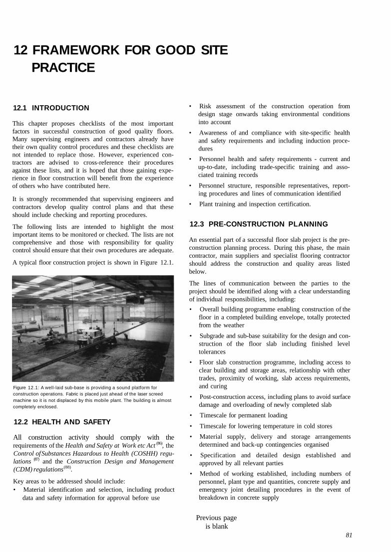
12 FRAMEWORK FOR GOOD SITEPRACTICE
12.1 INTRODUCTION
This chapter proposes checklists of the most importantfactors in successful construction of good quality floors.Many supervising engineers and contractors already havetheir own quality control procedures and these checklists arenot intended to replace those. However, experienced con-tractors are advised to cross-reference their proceduresagainst these lists, and it is hoped that those gaining expe-rience in floor construction will benefit from the experienceof others who have contributed here.
It is strongly recommended that supervising engineers andcontractors develop quality control plans and that theseshould include checking and reporting procedures.
The following lists are intended to highlight the mostimportant items to be monitored or checked. The lists are notcomprehensive and those with responsibility for qualitycontrol should ensure that their own procedures are adequate.
A typical floor construction project is shown in Figure 12.1.
Figure 12.1: A well-laid sub-base is providing a sound platform forconstruction operations. Fabric is placed just ahead of the laser screedmachine so it is not displaced by this mobile plant. The building is almostcompletely enclosed.
12.2 HEALTH AND SAFETY
All construction activity should comply with therequirements of the Health and Safety at Work etc Act (86), theControl of Substances Hazardous to Health (COSHH) regu-lations (87) and the Construction Design and Management(CDM) regulations (88).
Key areas to be addressed should include:• Material identification and selection, including product
data and safety information for approval before use
• Risk assessment of the construction operation fromdesign stage onwards taking environmental conditionsinto account
• Awareness of and compliance with site-specific healthand safety requirements and including induction proce-dures
• Personnel health and safety requirements - current andup-to-date, including trade-specific training and asso-ciated training records
• Personnel structure, responsible representatives, report-ing procedures and lines of communication identified
• Plant training and inspection certification.
12.3 PRE-CONSTRUCTION PLANNING
An essential part of a successful floor slab project is the pre-construction planning process. During this phase, the maincontractor, main suppliers and specialist flooring contractorshould address the construction and quality areas listedbelow.
The lines of communication between the parties to theproject should be identified along with a clear understandingof individual responsibilities, including:
• Overall building programme enabling construction of thefloor in a completed building envelope, totally protectedfrom the weather
• Subgrade and sub-base suitability for the design and con-struction of the floor slab including finished leveltolerances
• Floor slab construction programme, including access toclear building and storage areas, relationship with othertrades, proximity of working, slab access requirements,and curing
• Post-construction access, including plans to avoid surfacedamage and overloading of newly completed slab
• Timescale for permanent loading
• Timescale for lowering temperature in cold stores
• Material supply, delivery and storage arrangementsdetermined and back-up contingencies organised
• Specification and detailed design established andapproved by all relevant parties
• Method of working established, including numbers ofpersonnel, plant type and quantities, concrete supply andemergency joint detailing procedures in the event ofbreakdown in concrete supply
Previous pageis blank
81
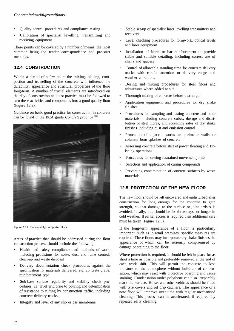
Concrete industrial ground floors
• Quality control procedures and compliance testing
• Calibration of specialist levelling, transmitting andreceiving equipment.
These points can be covered by a number of means, the mostcommon being the tender correspondence and pre-startmeetings.
12.4 CONSTRUCTION
Within a period of a few hours the mixing, placing, com-paction and trowelling of the concrete will influence thedurability, appearance and structural properties of the floorlong-term. A number of crucial elements are introduced onthe day of construction and best practice must be followed toturn these activities and components into a good quality floor(Figure 12.2).
Guidance on basic good practice for construction in concretecan be found in the BCA guide Concrete practice (89).
Figure 12.2: Successfully completed floor.
Areas of practice that should be addressed during the floorconstruction process should include the following:
• Health and safety compliance and methods of work,including provisions for noise, dust and fume control,clean-up and waste disposal
• Delivery documentation check procedures against thespecification for materials delivered, e.g. concrete grade,reinforcement type
• Sub-base surface regularity and stability check pro-cedures, i.e. level grid prior to pouring and determinationof resistance to rutting by construction traffic, includingconcrete delivery trucks
• Integrity and level of any slip or gas membrane
• Stable set-up of specialist laser levelling transmitters andreceivers
• Level checking procedures for formwork, optical levelsand laser equipment
• Installation of fabric or bar reinforcement to providestable and suitable detailing, including correct use ofchairs and spacers
• Control of allowable standing time for concrete deliverytrucks with careful attention to delivery range andweather conditions
• Dosing and mixing procedures for steel fibres andadmixtures where added at site
• Thorough mixing of concrete before discharge
• Application equipment and procedures for dry shakefinishes
• Procedures for sampling and testing concrete and othermaterials, including concrete cubes, dosage and distri-bution of steel fibres, and spreading rates of dry shakefinishes including dust and emission control
• Protection of adjacent works or perimeter walls orcolumns from splashes of concrete
• Assessing concrete before start of power floating and fin-ishing operations
• Procedures for sawing restrained-movement joints
• Selection and application of curing compounds
• Preventing contamination of concrete surfaces by wastematerials.
12.5 PROTECTION OF THE NEW FLOOR
The new floor should be left uncovered and undisturbed afterconstruction for long enough for the concrete to gainstrength, so that damage to the surface or joint arrises isavoided. Ideally, this should be for three days, or longer incold weather. If earlier access is required then additional caremust be taken (Figure 12.3).
If the long-term appearance of a floor is particularlyimportant, such as in retail premises, specific measures arerequired. These floors may incorporate dry shake finishes theappearance of which can be seriously compromised bydamage or staining to the floor.
Where protection is required, it should be left in place for asshort a time as possible and preferably removed at the end ofeach work shift. This will permit the concrete to losemoisture to the atmosphere without build-up of conden-sation, which may react with protective boarding and causestaining. Condensation under polythene can also irreparablymark the surface. Hoists and other vehicles should be fittedwith tyre covers and oil drip catchers. The appearance of anew floor will improve over time with regular mechanisedcleaning. This process can be accelerated, if required, byrepeated early cleaning.
82
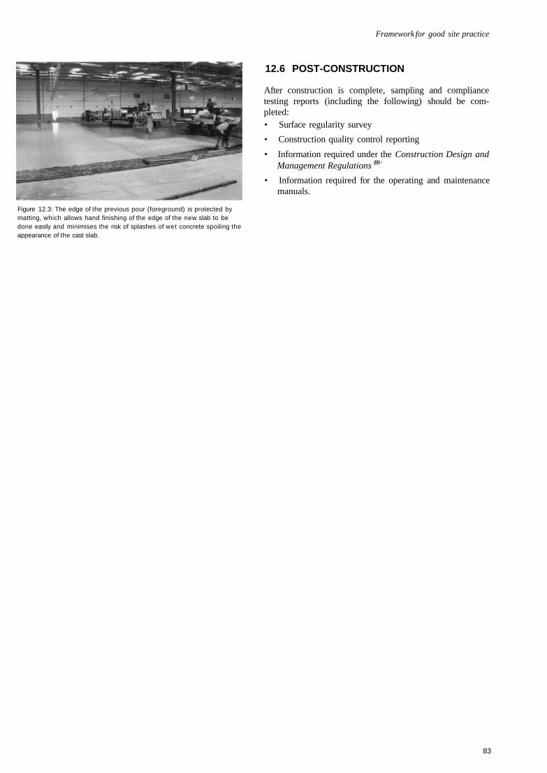
Framework for good site practice
Figure 12.3: The edge of the previous pour (foreground) is protected bymatting, which allows hand finishing of the edge of the new slab to bedone easily and minimises the risk of splashes of wet concrete spoiling theappearance of the cast slab.
12.6 POST-CONSTRUCTION
After construction is complete, sampling and compliancetesting reports (including the following) should be com-pleted:• Surface regularity survey
• Construction quality control reporting
• Information required under the Construction Design andManagement Regulations (88>
• Information required for the operating and maintenancemanuals.
83
13 MAINTENANCE
15.1 INTRODUCTION
Concrete floors require routine periodic inspection and main-tenance in order to provide the on-going serviceability forwhich the floor was designed. Floors provide an operationalplatform for equipment. These operations create wear andtear that must be addressed on an on-going basis. As in manysituations, failure to maintain concrete floors and jointsinvariably leads to higher long-term maintenance costs andlower efficiency - a 'stitch-in-time' philosophy of plannedmaintenance and repair should be adopted.
13.2 CLEANING
It is important to establish a cleaning regime that stops dirt anddust from building up; the operation of many types ofmaterials handling equipment on dirty/dusty floors will causeincreased wear on the floor. Power-floated concrete floors cannormally be easily cleaned with a wet scrubber and vacuum-type machine using neutral (non-acid) detergents. Dry vacuumand sweeping will also remove dust and dirt deposits.
13.3 SURFACE WEAR - ABRASION
Rates of wear of concrete floors depend on the types ofmaterials handling equipment, cleaning regime and trafficintensity on the floor. Many floors are sealed with acrylic orresin-type curing and sealing agents that penetrate thesurface of the slab. These agents can be re-applied by rolleror spray to heavily trafficked areas. Typically, in-surfacesealers are re-applied periodically.
In extreme cases of accelerated wear the surface may have tobe removed and resealed or reinstated.
13.4 SURFACE WEAR - SCOURING ANDIMPACT DAMAGE
Areas of impact damage from dropped goods or scouring fromMHE forks, etc. should be treated with a suitable epoxy mortaror resin to prevent further degradation of the affected area.Often the scraping of pallets and forks across the floor candamage the surface and cause joint arrises to spall. It isimportant to maintain pallets in good condition and to avoidunnecessary pushing of pallets and other equipment across thefloor surface. Early repair will reduce the risk of accelerateddegradation.
If heavy goods such as paper rolls are dropped, seriouscracking of the slab may occur, requiring sections of slabs to
be removed and reinstated. In these cases, dowels should bedrilled and resin-set into the existing slab to prevent verticalmovement between the old and new sections. Some advice isgiven in Concrete pavement maintenance manual (90).
13.5 JOINTS
Joints typically require most attention in any maintenanceplan, as they are the weakest feature of floors under intenseMHE traffic. The edges of formed free-movement joints areprone to damage and so are sometimes constructed asarmoured joints. These are more able to withstand wearalthough regular inspection and maintenance are stillrequired. Sawn restrained-movement joints generallyperform well although they are susceptible to heavy traf-ficking by small hard wheels (e.g. of pallet trucks). Inheavily trafficked areas, unprotected arrises of these jointsmay suffer damage if the joints are not maintained.
Joint sealants should be inspected regularly and their ability toprotect the arrises assessed. Once arrises are damaged thesealant may need to be replaced. Damage to arrises should berepaired as soon as possible as deterioration tends to accelerateonce it has started.
Soon after the slab is constructed a 'soft' elastomeric masticshould be installed in the joints: this will permit a degree ofmovement and 'stretching' as the joint opens. This masticprovides no support to the arrises but will keep the joint freefrom dirt and debris. Once the mastic has reached the limit ofits elasticity, it will de-bond from one of the joint faces andshould be replaced under general maintenance.
When movement of the joints has stabilised, the mastic isreplaced with a harder sealant that cannot accommodate suchlarge joint movement but can provide support to the jointarrises. This sealant should be regularly inspected as anyminor deterioration in the sealant can be successfully treatedbefore significant damage to the joint arrises occurs.
It may prove necessary to replace 'hard' sealants in heavilytrafficked MHE transfer aisles or collation areas periodically.
Before resealing joints, the cause of failure (e.g. splitting ordebonding of the sealant, chemical attack, spalling of thearrises) should be established.
Splitting or debonding of the sealant is most likely to be dueto excessive movement, which may have now stabilised. Theuse of a harder sealant is recommended for resealing wherelittle movement is anticipated.
If chemicals may come into contact with the floor, the sealantmanufacturer should be consulted for the most suitable
84

Maintenance
sealant. It should be noted that sealants often have lowerchemical resistance than the epoxy or polyurethane materialsused on floors where chemical spillage is likely.
Slight ravelling of joint arrises is not usually detrimental tothe operation of a joint. When the harder epoxy sealant isinstalled in the joint it will usually provide sufficient supportto deal with minor damage to the arris. Where significantdamage has occurred to the arris a concrete repair to re-formthe joint may need to be carried out. Manufacturers should beconsulted for details of the selection and application ofsuitable repair systems.
Joint sealants for use in cold stores must be suitable forinstallation and use of low temperatures.
13.6 CRACKS
As with joints, any cracks that develop should be monitoredand, where appropriate, repaired. Fine cracks may only be aconsideration of appearance, in which case they are best leftuntreated although they should be monitored as part of thefloor inspection and maintenance regime. If the arrises of acrack begin to spall or the crack widens, it should be treatedto avoid further deterioration. However, this should bebalanced against a need to leave new cracks untreated untilthey have become dormant i.e. not undergoing any furtheropening. Where cracks are not dormant and it is consideredessential to provide some degree of arris support, then semi-flexible sealants should be used.
85
REFERENCES
Readers should ensure that any standards and regulations consultedare the current issue.
This listing includes details of references that are included in theAppendices.
1. THE CONCRETE SOCIETY. Concrete industrial groundfloors - A guide to their design and construction.Crowthorne, 1994. Technical Report 34, Second edition.170pp.
2. THE CONCRETE SOCIETY. Concrete industrial groundfloors - Specification and control of surface regularity of freemovement areas. Supplement to Technical Report 34.Crowthorne, 1997. 32pp.
3. ASSOCIATION OF CONCRETE INDUSTRIAL FLOORCONTRACTORS. Guidance on specification, mix designand production of concrete for industrial floors, GoodConcrete Guide No. 1, The Concrete Society, Crowthorne,1998.24pp.
4. BUILDING RESEARCH ESTABLISHMENT. Classes ofimposed floor loads for warehouses. (Neal, F. R. and Judge,C. J.) Information paper IP 19/87. BRE, Garston, 1987. 4pp.
5. DEACON, R.C. Concrete ground floors. Their design, con-struction and finish. Cement & Concrete Association,Wexham Springs, 1986. 24pp. Ref: 48.034.
6. THE CONCRETE SOCIETY. The structural use of steelfabric reinforcement in ground-supported concrete floors. Tobe published 2003.
7. DANLEY CONSTRUCTION PRODUCTS andPERMABAN PRODUCTS LTD. Jointing systems inconcrete structures. Testing of dowel systems. School of CivilEngineering, Queensland University of Technology, May2002. 25pp.
8. BISHOP, J.W. The early age behaviour of concrete industrialground floor slabs. PhD thesis, University of Loughborough.December 2001. 255pp.
9. HULETT, T. Abrasion resistance of power-finished concreteindustrial floors; a state of the art review, Diploma inAdvanced Concrete Technology Project Report, Institute ofConcrete Technology, Crowthorne, 2002. 38pp.
10. BRITISH STANDARDS INSTITUTION. BS 8204-2: 2002,Screeds, bases and in-situ floorings. Concrete wearingsurfaces. Code of practice.
11. INTERNATIONAL ASSOCIATION OF COLD STORAGECONTRACTORS. Guidelines for the specification, designand construction of cold store floors. Burks Green &Partners, Newark and the Association, Bracknell, 1993.118pp.
12. BRITISH STANDARDS INSTITUTION. BS 6399-1: 1996Loading for buildings. Code of practice for dead andimposed loads.
13. BRITISH STANDARDS INSTITUTION. BS 5606: 1990Guide to accuracy in building.
14. BRITISH STANDARDS INSTITUTION. BS 7334: 1990Measuring instruments for building construction. 8 parts.
15. BRITISH STANDARDS INSTITUTION. BS 8110Structural use of concrete, Part 1: 1997 Code of practice fordesign and construction. Part 2: 1985 Code of practice forspecial circumstances.
16. BRITISH STANDARDS INSTITUTION. BS EN 1992-1.Draft Eurocode 2, Design of concrete structures, Part 1,General rules and rules for buildings.
17. THE CONCRETE SOCIETY. Diagnosis of deterioration inconcrete structures. Crowthorne, 2000. Technical Report 54.72pp.
18. PORTLAND CEMENT ASSOCIATION. Effects of sub-stances on concrete and guide to protective treatments. PCA,Skokie, Illinois, 2001. PCA R&D serial No 2154. IS001.10.
19. BRITISH STANDARDS INSTITUTION. BS 8204-6: 2001Screeds, bases and in-situ floorings. Synthetic resin floorings.Code of practice.
20. THE CONCRETE SOCIETY. Non-structural cracks inconcrete. Crowthorne, 1992. Technical Report 22, Thirdedition. 48pp.
21. PLIMMER, J. Delamination of concrete floor surfaces.Concrete. Vol. 32, No. 6, June 1998. pp. 20-22.
22. UK SLIP RESISTANCE GROUP, The measurement of floorslip resistance: Guidelines recommended by the UK SlipResistance Group, Issue 2, Circulated by RAPRA Tech-nology, Shrewsbury, June 2000. 36pp.
23. SIMPSON, D. and WATSON, N. Surface blemishes onpower-trowelled concrete floors due to aggregate particles.Concrete. Vol. 35, No. 8, September 2001. pp. 25-26.
24. HIGHWAYS AGENCY. Manual of Contract Documents forHighways Works. Volume 1, Specification for highwaysworks, Series 600 Earthworks. London.
25. HIGHWAYS AGENCY. Manual of Contract Documents forHighways Works. Volume 1, Specification for highwaysworks, Series 800, Road pavements - Unbound materials.London.
26. WESTERGAARD, H.M. Computation of stresses inconcrete roads, Proceedings of the fifth annual meeting ofthe Highway Research Board, Vol. 5, Part 1, 1925. pp.90-112.
86
References
27. WESTERGAARD, H.M. Stresses in concrete pavementscomputed by theoretical analysis. Public Roads. Vol. 7, No.2, April 1926.
28. DARTER, M.I., HALL, K.T. and KUO, C-M. Support underPortland cement concrete pavements. Transportation ResearchBoard, Washington DC, 1995. NCHRP Report 372. 50pp.
29. BRITISH STANDARDS INSTITUTION. BS 5930: 1999Code of practice for site investigations.
30. BRITISH STANDARDS INSTITUTION. BS 1377: 1990Methods of test for soils for civil engineering purposes.Multiple parts.
31. HIGHWAYS AGENCY. Manual of Contract Documents forHighways Works. Volume 1, Specification for highwaysworks, Series 1000, Road pavements - Concrete and cementbound materials. London.
32. SIMPSON, D. Toward tolerant tolerances. Concrete. Vol. 35,No. 3, March 2001. pp. 4 5 - 7 .
33. BRITISH STANDARDS INSTITUTION. CP 102: 1973Code of practice for protection of buildings against waterfrom the ground.
34. BRITISH STANDARDS INSTITUTION. BS 8103-1: 1995Structural design of low-rise buildings. Code of practice forstability, site investigation, foundations and ground floorslabs for housing.
35. CARD, G.B. Protecting development from methane, Con-struction Industry Research and Information Association,London, 1996. Report 149. 190pp.
36. BRITISH STANDARDS INSTITUTION. BS 4449: 1997Specification for carbon steel bars for the reinforcement ofconcrete. To be replaced by BS EN 10080.
37. BRITISH STANDARDS INSTITUTION. DD ENV 10080:1996 Steel for the reinforcement of concrete. Due to replace BS4483.
38. BRITISH STANDARDS INSTITUTION. BS 8666: 2000Specification for scheduling, dimensioning, bending andcutting of steel reinforcement for concrete.
39. BRITISH STANDARDS INSTITUTION. BS 4483: 1998Steel fabric for the reinforcement of concrete. To be replacedby BS EN 10080.
40. JAPAN SOCIETY OF CIVIL ENGINEERS. Method of testfor flexural strength and flexural toughness of SFRC,Standard JSCE SF-4, 1985. Also published by JapanConcrete Institute.
41. BRITISH STANDARDS INSTITUTION. BS 7973 Spacersand chairs for steel reinforcement and their specification.Part 1. 2001 Product performance requirements. Part 2. 2001Fixing and application of spacers and chairs and tying ofreinforcement.
42. COLLEY, B.E. and HUMPHREY, H.A., Aggregate interlockat joints in concrete pavements. Portland Cement Asso-ciation, Skokie, USA. 1967 Development Bulletin D124.(Also Highway Research Record No. 189, pp. 1-18.)
43. BRITISH STANDARDS INSTITUTION. BS 8000-16: 1997Workmanship on building sites. Code of practice for sealing
joints in buildings using sealants.
44. CHANDLER, J.W.E. Design of floors on ground. BritishCement Association, Crowthorne, 1992. Technical Report550. 22pp.
45. CHANDLER, J.W.E. and NEAL, F.R. The design of ground-supported concrete industrial floor slabs. British CementAssociation, Crowthorne, 1988. Interim Technical Note 11.16pp.
46. SHENTU, L., JIANG, D. and HSU, C.T. Load carryingcapacity for slabs on grade. Journal of Structural Engineering,ASCE. Vol. 123, No. 1, January 1997. pp. 95-103.
47. CLEMENTS, M. Synthetics as concrete reinforcement.Concrete. Vol. 36, No. 8, September 2002. pp. 37-38.
48. BRITISH STANDARDS INSTITUTION. BS EN 1990: 2002Eurocode. Basis of structural design.
49. MEYERHOF, G.G. Load carrying capacity of concretepavements. Journal of the Soil Mechanics and FoundationsDivision, Proceedings of the American Society of CivilEngineers. Vol. 88, June 1962 pp. 89-166.
50. LOSBERG, A. Pavements and slabs on grade with struc-turally active reinforcement. ACI Journal, Proceedings. Vol.75, No. 12, December 1978. pp. 647-657.
51. BAUMANN, R.A. and WEISGERBER, F.E. Yield-line-analysis of slabs-on-grade. Journal of Structural Engineering,ASCE. Vol. 109, No. 7, July 1983. pp.1553- 1568.
52. RAO, K.S.S. and SINGH, S. Concentrated load-carryingcapacity of concrete slabs on grade. Journal of StructuralEngineering, ASCE. Vol. 112, No. 12, December 1986. pp.2628-2645.
53. BECKETT, D., VAN DE WOESTYNE, T. and CALLENS,S. Corner and edge loading on concrete industrial groundfloors reinforced with steel fibres. Concrete. Vol. 33, No. 4,March 1999. pp. 22-24.
54. BECKETT, D. Strength and serviceability design ofconcrete industrial ground floors. Industrial Floors '03. Pro-ceedings of Industrial Colloquim, Technical Academy ofEsslingen, Germany, January 2003. Ed. Seidler, P. 2003. pp.601-612.
55. HETENYI, M. Beams on elastic foundations. University ofMichigan Press, Ninth printing, 1971.
56. YODER, E.J. and WITCZAK, M.W. Principles of pavementdesign. John Wiley and Sons, New York, Second Edition,1975. 711pp.
57. FRIBERG, B.F. Design of dowels in transverse joints ofconcrete pavements. Proceedings of the American Society ofCivil Engineers. Vol. 64, No. 9, 1938. pp. 1809-1828.
58. BRADBURY, R.D. Design of joints in concrete pavements.Proceedings of the Highway Research Board. Vol. 12, 1932.pp. 105-136.
59. WALKER, W.W. and HOLLAND, J.A. Plate dowels forslabs on ground (dowels for the 21 st century). Concrete Inter-national. Vol. 20, No. 7, July 1998. pp. 32-38.
60. OZBEKI, M.A. et al. Evaluation methodology for jointedconcrete pavements. Transportation Research Record, No.1043. Pavement system analysis Kaplan, E.W. (Ed.) NationalResearch Council, Washington, 1986. pp. 1-8.
87
Concrete industrial ground floors
61. TIMOSHENKO, S. and LESSELS, J.M. Applied elasticity.Westinghouse Technical Night School Press, Pittsburgh,Pennsylvania, 1925.
62. RILEM TC 162-TDF. (Vandewalle, L. et al.) Test and designmethods for steel fibre reinforced concrete - design method.Materials and Structures. Vol. 33, No. 225, March 2000. pp.75-81.
63. TIMMS, A.G. Evaluating subgrade friction-reducingmediums for rigid pavements. Highway Research Board. No.60. 1964. pp. 48-59.
64. BRITISH STANDARDS INSTITUTION. BS 5328Concrete. (Four parts) To be replaced by BS EN 206-1.
65. BRITISH STANDARDS INSTITUTION. BS EN 206-1:2002 Concrete. Two parts.
66. BRITISH STANDARDS INSTITUTION. BS 8500: 2002Complementary British Standard to BS EN 206, Concrete.Two parts.
67. NEVILLE, A.M. Properties of concrete. Addison WesleyLongman, Harlow, Fourth Edition 1995. 844pp.
68. BUILDING RESEARCH ESTABLISHMENT. Shrinkage ofnatural aggregates in concrete. Digest 357. BRE, Garston,1991.4pp.
69. BRITISH STANDARDS INSTITUTION. BS EN 1367-4:1998 Tests for thermal and weathering properties ofaggregates. Determination of drying shrinkage.
70. BAMFORTH, P.B. and PRICE, W.F. Concreting deep liftsand large volume pours. Construction Industry Researchand Information Association, London, 1995. Report 135.84pp.
71. HARRISON, T.A. Early-age thermal crack control inconcrete. Construction Industry Research and InformationAssociation, London, Second edition 1992. Report 91.57pp.
72. BRITISH STANDARDS INSTITUTION. BS EN 12350-2:2000. Testing fresh concrete. Slump test.
73. THE CONCRETE SOCIETY. The influence of cementcontent on the performance of concrete. Crowthorne, 1999.Discussion Document. Ref: CS 125. 48pp.
74. SADEGZADEH, M. Abrasion resistance of concrete. PhDthesis, University of Aston, Birmingham, 1984.
75. SADEGZADEH, M., PAGE, C.L. and KETTLE, R.J.Surface microstructure and abrasion resistance of concrete.Cement and Concrete Research. Vol. 17, 1987. pp. 581-590.
76. BRITISH STANDARDS INSTITUTION. BS EN 197-1:2000 Cement. Composition, specifications and conformitycriteria for common cements.
77. THE CONCRETE SOCIETY. The use ofGGBS and PFA inconcrete. Crowthorne, 1991. Technical Report 40. 144pp.
78. THE CONCRETE SOCIETY. Microsilica in concrete.Crowthorne, 1993. Technical Report 41. 56pp.
79. AMERICAN CONCRETE INSTITUTE. ACI 223-98Standard practice for the use of shrinkage-compensatingconcrete. Farmington Hills, 1998. 28pp.
80. AMERICAN SOCIETY FOR TESTING AND MATERIALS.ASTM C845-96 Standard specification for expansivehydraulic cement. West Conshohocken, Pennsylvania, USA.
81. BRITISH STANDARDS INSTITUTION. BS 882: 1992Specification for aggregates from natural sources forconcrete. Replaced by BS EN 12620: 2002.
82. BRITISH STANDARDS INSTITUTION. BS EN 12620:2002. Aggregates for concrete. Replaces BS 882.
83. THE CONCRETE SOCIETY. A guide to the selection ofadmixtures for concrete. Crowthorne, 2002. Technical Report18. 68pp.
84. ASSOCIATION OF CONCRETE INDUSTRIAL FLOORCONTRACTORS. Dry shake finishes for concrete industrialfloors. An introductory guide. The Concrete Society,Crowthorne, 2001. Supplement to Concrete, November/December 2001. Ref: CS 142. 24pp.
85. VASSOU, V. and KETTLE, R.J. Abrasion resistance of fibrereinforced concrete floors. Materials Week InternationalCongress, Munich, March 2000. Paper 349.
86. Health and Safety at Work etc Act. HMSO, London, 1994.
87. The Control of Substances Hazardous to Health Regulations,SI 437. The Stationery Office, 1999.
88. Construction (Design and Management) Regulations, SI1994/3247. HMSO.
89. BRITISH CEMENT ASSOCIATION. (Blackledge, G.F.,revised by Binns, R.A.) Concrete practice. Crowthorne,Third edition 2002. Ref. 48.037. 72pp.
90. BRITPAVE/Burks Green. Concrete pavement maintenancemanual. The Concrete Society, Crowthorne, 2001. Ref: CS138. 112pp.
91. DEUTSCHES INSTITUT FUR NORMUNG. Lagersystememit leitlinengefuhrten flurforderzeugen. {Warehouse systemswith guided industrial trucks: requirements on the ground,the warehouse and other requirements). DIN 15185. 7pp.Beuth Verlag, Berlin GmbH, Berlin, August 1991.
92. DEUTSCHES INSTITUT FUR NORMUNG. Toleranzen inhochbau. Bauwerke. (Tolerances for buildings. Structures.)DIN 18202. 8pp. Beuth Verlag, Berlin GmbH, Berlin, April1997. (English translation)
93. FACE, A. Floor flatness and levelness: the F-number system.The Construction Specifier. Vol. 40, No. 4 April, 1987. pp.124-132.
94. AMERICAN SOCIETY FOR TESTING ANDMATERIALS ASTM 1155M-96. Standard test method fordetermining FF floor flatness and FL floor levelness numbers.West Conshohocken, Pennsylvania, USA.
95. COMITÉ EURO-INTERNATIONALE DU BÉTON. Theapplication of yield-line theory to calculations of the flexuralstrength of slabs and flat-slab floors. Bulletin d'InformationNo. 35. CEB, Lausanne, 1990. 180pp.
88
APPENDICES
APPENDIX BWORKED EXAMPLE: THICKNESS DESIGN OF AGROUND-SUPPORTED FLOOR SLAB
APPENDIX CFLOOR REGULARITY
C1 Developments in floor surveying
C2 Alternative method for surveying defined-movement areas
C3 Application of truck dimensions
C4 Specifications outside the UK
APPENDIX DPILED SLABS
D1 Introduction
D2 Alternative design approaches
D3 Structural analysis
D4 .. Section analysis
D5 Joints in piled slabs
APPENDIX EDESIGN WITH FABRIC REINFORCEMENT
E1 Supplement to Chapter 9, strength andserviceability of slabs
E2 Extension to Appendix B, thickness designof a ground-supported floor slab
APPENDIX FSOURCES OF INFORMATION
89
APPENDIX AMODEL DESIGN BRIEF FOR CONCRETEINDUSTRIAL GROUND FLOORS
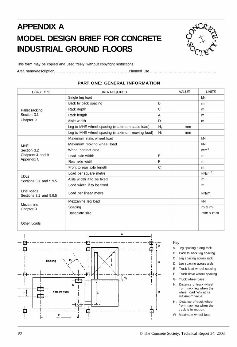
APPENDIX AMODEL DESIGN BRIEF FOR CONCRETEINDUSTRIAL GROUND FLOORS
This form may be copied and used freely, without copyright restrictions.
Area name/description Planned use
PART ONE: GENERAL INFORMATION
LOAD TYPE
Pallet rackingSection 3.1Chapter 9
MHESection 3.2Chapters 4 and 9Appendix C
UDLsSections 3.1 and 9.9.5
Line loadsSections 3.1 and 9.9.5
MezzanineChapter 9
Other Loads
DATA REQUIRED
Single leg load
Back to back spacing B
Rack depth C
Rack length A
Aisle width D
Leg to MHE wheel spacing (maximum static load) H1
Leg to MHE wheel spacing (maximum moving load) H2
Maximum static wheel load
Maximum moving wheel load
Wheel contact area
Load axle width E
Rear axle width F
Front to rear axle length C
Load per square metre
Aisle width if to be fixed
Load width if to be fixed
Load per linear metre
Mezzanine leg load
Spacing
Baseplate size
VALUE
mm
mm
UNITS
kN
mm
m
m
m
kN
kN
mm2
m
m
m
kN/m2
m
m
kN/m
kN
m x m
mm x mm
KeyA Leg spacing along rack
B Back to back leg spacing
C Leg spacing across rack
D Leg spacing across aisle
E Truck load wheel spacing
F Truck drive wheel spacing
G Truck wheel base
H, Distance of truck wheelfrom rack leg when thewheel load Wis at itsmaximum value.
H2 Distance of truck wheelfrom rack leg when thetruck is in motion.
W Maximum wheel load.
90 © The Concrete Society, Technical Report 34, 2003
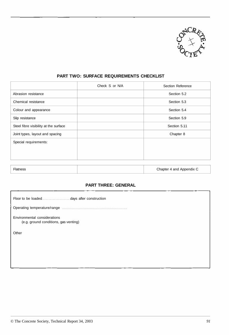
PART TWO: SURFACE REQUIREMENTS CHECKLIST
Abrasion resistance
Chemical resistance
Colour and appearance
Slip resistance
Steel fibre visibility at the surface
Joint types, layout and spacing
Special requirements:
Check S or N/A Section Reference
Section 5.2
Section 5.3
Section 5.4
Section 5.9
Section 5.11
Chapter 8
Flatness Chapter 4 and Appendix C
PART THREE: GENERAL
Floor to be loaded days after construction
Operating temperature/range
Environmental considerations(e.g. ground conditions, gas venting)
Other
© The Concrete Society, Technical Report 34, 2003 91
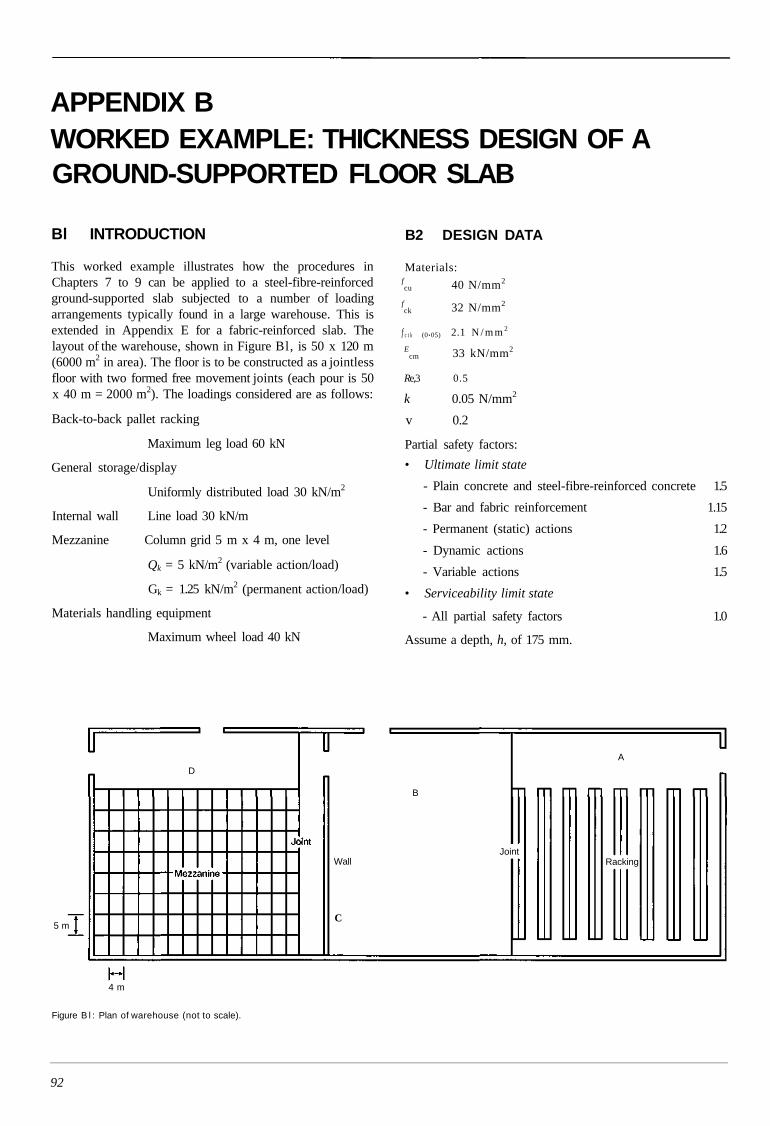
APPENDIX BWORKED EXAMPLE: THICKNESS DESIGN OF AGROUND-SUPPORTED FLOOR SLAB
Bl INTRODUCTION
This worked example illustrates how the procedures inChapters 7 to 9 can be applied to a steel-fibre-reinforcedground-supported slab subjected to a number of loadingarrangements typically found in a large warehouse. This isextended in Appendix E for a fabric-reinforced slab. Thelayout of the warehouse, shown in Figure Bl, is 50 x 120 m(6000 m2 in area). The floor is to be constructed as a jointlessfloor with two formed free movement joints (each pour is 50x 40 m = 2000 m2). The loadings considered are as follows:
Back-to-back pallet racking
Maximum leg load 60 kN
General storage/display
Uniformly distributed load 30 kN/m2
Internal wall Line load 30 kN/m
Mezzanine Column grid 5 m x 4 m, one level
Qk = 5 kN/m2 (variable action/load)
Gk = 1.25 kN/m2 (permanent action/load)
Materials handling equipment
Maximum wheel load 40 kN
B2 DESIGN DATA
Materials:fcu 40 N/mm2
fck 32 N/mm2
f c t k (0.05) 2.1 N / m m 2
Ecm 33 kN/mm2
Re,3 0.5
k 0.05 N/mm2
v 0.2
Partial safety factors:
• Ultimate limit state
- Plain concrete and steel-fibre-reinforced concrete 1.5
- Bar and fabric reinforcement 1.15
- Permanent (static) actions 1.2
- Dynamic actions 1.6
- Variable actions 1.5
• Serviceability limit state
- All partial safety factors 1.0
Assume a depth, h, of 175 mm.
Figure B l : Plan of warehouse (not to scale).
92
D
B
Wall
C
JointRacking
A
5 m
4 m
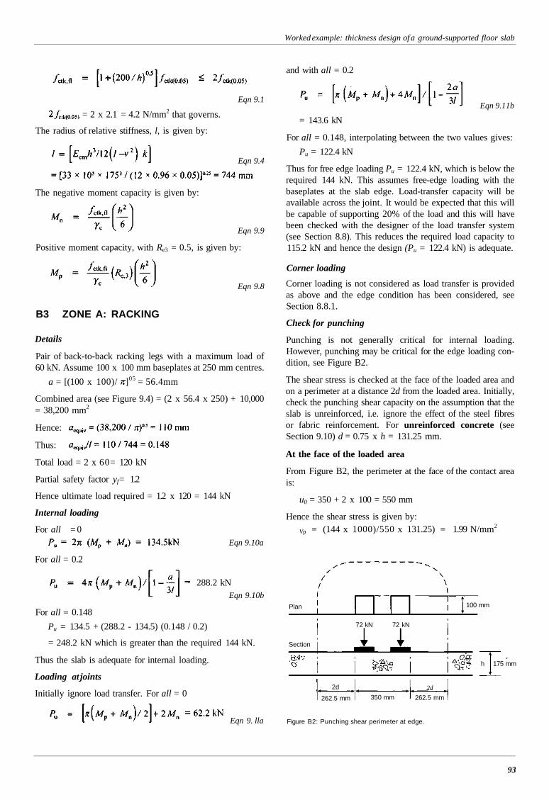
Worked example: thickness design of a ground-supported floor slab
B3 ZONE A: RACKING
Details
Pair of back-to-back racking legs with a maximum load of60 kN. Assume 100 x 100 mm baseplates at 250 mm centres.
a = [(100 x 100)/ ]05 = 56.4mm
Combined area (see Figure 9.4) = (2 x 56.4 x 250) + 10,000= 38,200 mm2
Hence:
Thus:
Total load = 2 x 60= 120 kN
Partial safety factor yf= 1.2
Hence ultimate load required = 1.2 x 120 = 144 kN
Internal loading
For all = 0Eqn 9.10a
For all = 0.2
288.2 kNEqn 9.10b
For all = 0.148
Pu = 134.5 + (288.2 - 134.5) (0.148 / 0.2)
= 248.2 kN which is greater than the required 144 kN.
Thus the slab is adequate for internal loading.
Loading at joints
Initially ignore load transfer. For all = 0
Eqn 9. lla
Eqn 9.1
= 2 x 2.1 = 4.2 N/mm2 that governs.
The radius of relative stiffness, l, is given by:
Eqn 9.4
The negative moment capacity is given by:
Eqn 9.9
Positive moment capacity, with Re3 = 0.5, is given by:
Eqn 9.8
and with all = 0.2
Eqn 9.11b
= 143.6 kN
For all = 0.148, interpolating between the two values gives:
Pu = 122.4 kN
Thus for free edge loading Pu = 122.4 kN, which is below therequired 144 kN. This assumes free-edge loading with thebaseplates at the slab edge. Load-transfer capacity will beavailable across the joint. It would be expected that this willbe capable of supporting 20% of the load and this will havebeen checked with the designer of the load transfer system(see Section 8.8). This reduces the required load capacity to115.2 kN and hence the design (Pu = 122.4 kN) is adequate.
Corner loading
Corner loading is not considered as load transfer is providedas above and the edge condition has been considered, seeSection 8.8.1.
Check for punching
Punching is not generally critical for internal loading.However, punching may be critical for the edge loading con-dition, see Figure B2.
The shear stress is checked at the face of the loaded area andon a perimeter at a distance 2d from the loaded area. Initially,check the punching shear capacity on the assumption that theslab is unreinforced, i.e. ignore the effect of the steel fibresor fabric reinforcement. For unreinforced concrete (seeSection 9.10) d = 0.75 x h = 131.25 mm.
At the face of the loaded area
From Figure B2, the perimeter at the face of the contact areais:
93
u0 = 350 + 2 x 100 = 550 mm
Hence the shear stress is given by:
Vp = (144 x 1000)/550 x 131.25) = 1.99 N/mm2
72 kN 72 kN
2d
262.5 mm 350 mm2d
262.5 mm
h 175 mm
Figure B2: Punching shear perimeter at edge.
Plan 100 mm
Section
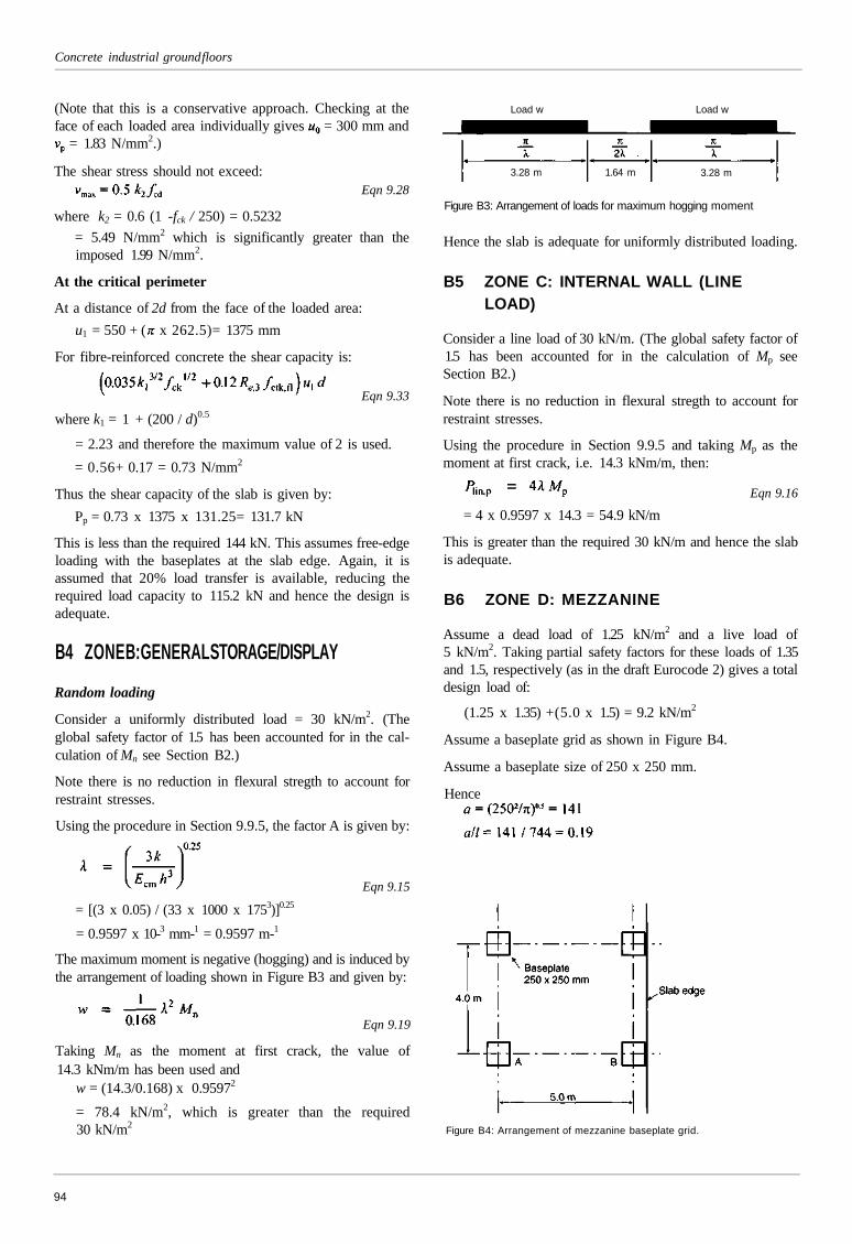
Concrete industrial ground floors
(Note that this is a conservative approach. Checking at theface of each loaded area individually gives = 300 mm and
= 1.83 N/mm2.)
The shear stress should not exceed:Eqn 9.28
where k2 = 0.6 (1 -fck / 250) = 0.5232
= 5.49 N/mm2 which is significantly greater than theimposed 1.99 N/mm2.
At the critical perimeter
At a distance of 2d from the face of the loaded area:
u1 = 550 + ( x 262.5)= 1375 mm
For fibre-reinforced concrete the shear capacity is:
Eqn 9.33
where k1 = 1 + (200 / d)0.5
= 2.23 and therefore the maximum value of 2 is used.
= 0.56+ 0.17 = 0.73 N/mm2
Thus the shear capacity of the slab is given by:
Pp = 0.73 x 1375 x 131.25= 131.7 kN
This is less than the required 144 kN. This assumes free-edgeloading with the baseplates at the slab edge. Again, it isassumed that 20% load transfer is available, reducing therequired load capacity to 115.2 kN and hence the design isadequate.
B4 ZONE B: GENERAL STORAGE/DISPLAYRandom loading
Consider a uniformly distributed load = 30 kN/m2. (Theglobal safety factor of 1.5 has been accounted for in the cal-culation of Mn see Section B2.)
Note there is no reduction in flexural stregth to account forrestraint stresses.
Using the procedure in Section 9.9.5, the factor A is given by:
Eqn 9.15
= [(3 x 0.05) / (33 x 1000 x 1753)]0.25
= 0.9597 x 10⁻³ mm-1 = 0.9597 m-1
The maximum moment is negative (hogging) and is induced bythe arrangement of loading shown in Figure B3 and given by:
Eqn 9.19
Taking Mn as the moment at first crack, the value of14.3 kNm/m has been used and
w = (14.3/0.168) x 0.95972
= 78.4 kN/m2, which is greater than the required30 kN/m2
Load w Load w
3.28 m 1.64 m 3.28 m
Figure B3: Arrangement of loads for maximum hogging moment
Hence the slab is adequate for uniformly distributed loading.
B5 ZONE C: INTERNAL WALL (LINELOAD)
Consider a line load of 30 kN/m. (The global safety factor of1.5 has been accounted for in the calculation of Mp seeSection B2.)
Note there is no reduction in flexural stregth to account forrestraint stresses.
Using the procedure in Section 9.9.5 and taking Mp as themoment at first crack, i.e. 14.3 kNm/m, then:
Eqn 9.16
= 4 x 0.9597 x 14.3 = 54.9 kN/m
This is greater than the required 30 kN/m and hence the slabis adequate.
B6 ZONE D: MEZZANINE
Assume a dead load of 1.25 kN/m2 and a live load of5 kN/m2. Taking partial safety factors for these loads of 1.35and 1.5, respectively (as in the draft Eurocode 2) gives a totaldesign load of:
(1.25 x 1.35) +(5.0 x 1.5) = 9.2 kN/m2
Assume a baseplate grid as shown in Figure B4.
Assume a baseplate size of 250 x 250 mm.
Hence
Figure B4: Arrangement of mezzanine baseplate grid.
94
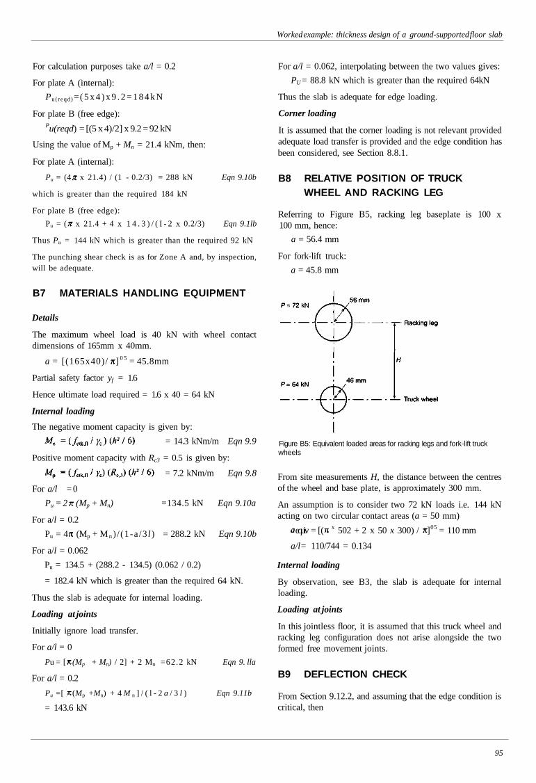
Worked example: thickness design of a ground-supported floor slab
For calculation purposes take a/l = 0.2
For plate A (internal):
Pu(reqd) = ( 5 x 4 ) x 9 . 2 = 1 8 4 k N
For plate B (free edge):Pu(reqd) = [(5 x 4)/2] x 9.2 = 92 kN
Using the value of Mp + Mn = 21.4 kNm, then:
For plate A (internal):
Pu = (4 x 21.4) / (1 - 0.2/3) = 288 kN Eqn 9.10b
which is greater than the required 184 kN
For plate B (free edge):
Pu = ( x 21.4 + 4 x 1 4 . 3 ) / ( I - 2 x 0.2/3) Eqn 9.1lb
Thus Pu = 144 kN which is greater than the required 92 kN
The punching shear check is as for Zone A and, by inspection,will be adequate.
B7 MATERIALS HANDLING EQUIPMENT
Details
The maximum wheel load is 40 kN with wheel contactdimensions of 165mm x 40mm.
a = [(165x40)/ ] 0 5 = 45.8mm
Partial safety factor yf = 1.6
Hence ultimate load required = 1.6 x 40 = 64 kN
Internal loading
For a/l = 0
Pu = 2 (Mp + Mn) =134.5 kN Eqn 9.10a
For a/l = 0.2
Pu = 4 (Mp + M n ) / (1-a /3 l ) = 288.2 kN Eqn 9.10b
For a/l = 0.062
Pu = 134.5 + (288.2 - 134.5) (0.062 / 0.2)
= 182.4 kN which is greater than the required 64 kN.
Thus the slab is adequate for internal loading.
Loading at joints
Initially ignore load transfer.
For a/l = 0
Pu = [ (Mp + Mn) / 2] + 2 Mn =62.2 kN Eqn 9. lla
For a/l = 0.2
Pu =[ (Mp +Mn) + 4 M n ] / ( l - 2 a / 3 l ) Eqn 9.11b
= 143.6 kN
For a/l = 0.062, interpolating between the two values gives:
PU = 88.8 kN which is greater than the required 64kN
Thus the slab is adequate for edge loading.
Corner loading
It is assumed that the corner loading is not relevant providedadequate load transfer is provided and the edge condition hasbeen considered, see Section 8.8.1.
B8 RELATIVE POSITION OF TRUCKWHEEL AND RACKING LEG
Referring to Figure B5, racking leg baseplate is 100 x100 mm, hence:
a = 56.4 mm
For fork-lift truck:
a = 45.8 mm
Figure B5: Equivalent loaded areas for racking legs and fork-lift truckwheels
From site measurements H, the distance between the centresof the wheel and base plate, is approximately 300 mm.
An assumption is to consider two 72 kN loads i.e. 144 kNacting on two circular contact areas (a = 50 mm)
equiv = [( x 502 + 2 x 50 x 300) / ]05 = 110 mm
a/l= 110/744 = 0.134
Internal loading
By observation, see B3, the slab is adequate for internalloading.
Loading at joints
In this jointless floor, it is assumed that this truck wheel andracking leg configuration does not arise alongside the twoformed free movement joints.
B9 DEFLECTION CHECK
From Section 9.12.2, and assuming that the edge condition iscritical, then
95
The negative moment capacity is given by:
= 14.3 kNm/m Eqn 9.9
Positive moment capacity with Rc3 = 0.5 is given by:
= 7.2 kNm/m Eqn 9.8

Concrete industrial ground floors
Eqn 9.35
kl2 = 0.05 x 7442 = 27,707
0.442 / kl2= 1.6 x 10⁻⁵
Taking P = 120 kN, the deflection e = 1.92 mm.Assume no load transfer.
For the serviceability limit state the partial safety factors aretaken as unity.
96
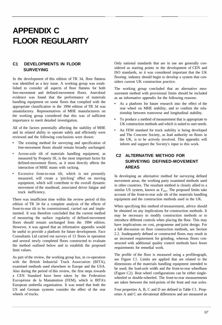
APPENDIX CFLOOR REGULARITY
C1 DEVELOPMENTS IN FLOORSURVEYING
In the development of this edition of TR 34, floor flatnesswas identified as a key issue. A working group was estab-lished to consider all aspects of floor flatness for bothfree-movement and defined-movement floors. Anecdotalevidence was found that the performance of materialshandling equipment on some floors that complied with theappropriate classification in the 1994 edition of TR 34 wasunsatisfactory. Representatives of MHE manufacturers onthe working group considered that this was of sufficientimportance to merit detailed investigation.
All of the factors potentially affecting the stability of MHEand its related ability to operate safely and efficiently werereviewed and the following conclusions were drawn:
The existing method for surveying and specification offree-movement floors should remain broadly unchanged.
Across-axle tilt of materials handling equipment, asmeasured by Property III, is the most important factor fordefined-movement floors, as it most directly affects theinteraction of MHE masts with racking.
Excessive front-to-rear tilt, which is not presentlymeasured, will create a 'pitching' effect on movingequipment, which will contribute to the overall dynamicmovement of the masthead, associated driver fatigue andtruck inefficiency.
There was insufficient time within the review period of thisedition of TR 34 for a complete analysis of the effects offront-to-rear tilt to be commissioned, carried out and imple-mented. It was therefore concluded that the current methodof measuring the surface regularity of defined-movementfloors should remain unchanged from the 1994 edition.However, it was agreed that an informative appendix wouldbe useful to provide a platform for future development. FaceConsultants Ltd carried out surveys of 13 floors in operationand several newly completed floors constructed to evaluatethe method outlined below and to establish the proposedlimit values.
As part of the review, the working group has, in co-operationwith the British Industrial Truck Association (BITA),examined methods used elsewhere in Europe and the USA.Also during the period of this review, the first steps towardsa CEN Standard have been taken by the FederationEuropénne de la Manutention (FEM), which is BITA'sEuropean umbrella organisation. It was noted that both theUS and German systems consider the effect of the rearwheels of trucks.
Only national standards that are in use are generally con-sidered as starting points in the development of CEN andISO standards, so it was considered important that the UKflooring industry should begin to develop a system that con-siders current UK construction practice.
The working group concluded that an alternative mea-surement method with provisional limits should be includedas an informative appendix for the following reasons:
As a platform for future research into the effect of therear wheel on MHE stability, and to confirm the rela-tionship between transverse and longitudinal stability.
To produce a method of measurement that is appropriate toUK construction methods and which is suited to user needs.
An FEM standard for truck stability is being developedand The Concrete Society, as lead authority on floors inthe UK, is to be actively involved. This appendix willinform and support the Society's input to this work.
C2 ALTERNATIVE METHOD FORSURVEYING DEFINED-MOVEMENTAREAS
In developing an alternative method for surveying definedmovement areas, the working party examined methods usedin other countries. The resultant method is closely allied to asimilar US system, known as Fmin. The proposed limits takeaccount of the front-to-rear axle tilt of the materials handlingequipment and the construction methods used in the UK.
When specifying this method of measurement, advice shouldbe obtained on any implications for construction methods. Itmay be necessary to modify construction methods or tointroduce different controls when placing the floor. This mayhave implications on cost, programme and joint design. Fora full discussion on floor construction methods, see Section2.2. Inadequately defined or constructed floors may result inan increased requirement for grinding, whereas floors con-structed with additional quality control methods have fewerrequirements for remedial work.
The profile of the floor is measured using a profileograph,see Figure Cl. Limits are applied that are related to thedimensions of the materials handling equipment intended tobe used; the load-axle width and the front-to-rear wheelbase(Figure C2). Rear wheel configurations can be either single-wheeled or double-wheeled. The front-to-rear measurementsare taken between the mid-points of the front and rear axles.
Four properties A, B, C and D are defined in Table C1. Prop-erties A and C are elevational differences and are measured as
97
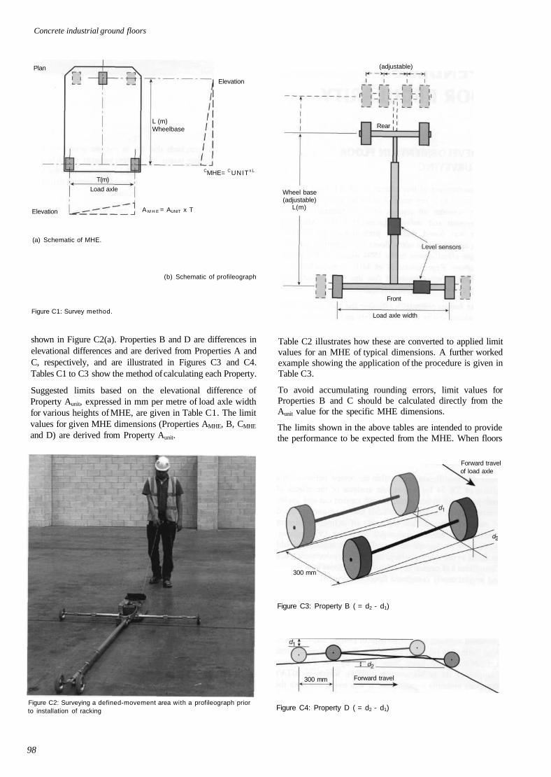
Concrete industrial ground floors
Plan (adjustable)
Elevation
L (m)Wheelbase
CMHE= CUNIT x L
Elevation
(a) Schematic of MHE.
A M H E = AUNIT x T
(b) Schematic of profileograph
Figure C1: Survey method.
shown in Figure C2(a). Properties B and D are differences inelevational differences and are derived from Properties A andC, respectively, and are illustrated in Figures C3 and C4.Tables C1 to C3 show the method of calculating each Property.
Suggested limits based on the elevational difference ofProperty Aunit, expressed in mm per metre of load axle widthfor various heights of MHE, are given in Table C1. The limitvalues for given MHE dimensions (Properties AMHE, B, CMHE
and D) are derived from Property Aunit.
Figure C2: Surveying a defined-movement area with a profileograph priorto installation of racking
Rear
Wheel base(adjustable)
L(m)
Front
Load axle width
Table C2 illustrates how these are converted to applied limitvalues for an MHE of typical dimensions. A further workedexample showing the application of the procedure is given inTable C3.
To avoid accumulating rounding errors, limit values forProperties B and C should be calculated directly from theAunit value for the specific MHE dimensions.
The limits shown in the above tables are intended to providethe performance to be expected from the MHE. When floors
Forward travelof load axle
300 mm
Figure C3: Property B ( = d2 - d1)
Figure C4: Property D ( = d2 - d1)
98
Load axle
T(m)
Forward travel300 mm
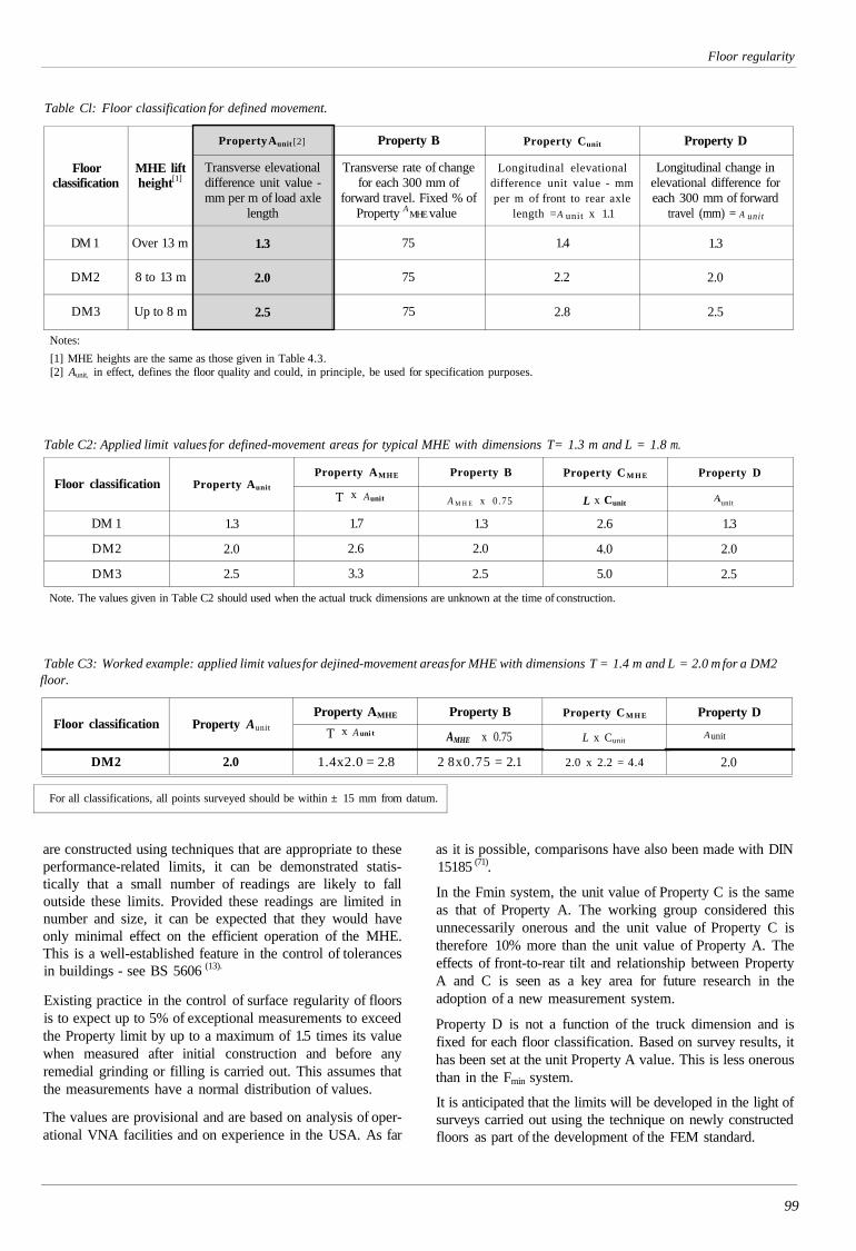
Floor regularity
Table Cl: Floor classification for defined movement.
Floorclassification
DM 1
DM2
DM3
MHE liftheight [1]
Over 13 m
8 to 13 m
Up to 8 m
Property Aunit [2]
Transverse elevationaldifference unit value -mm per m of load axle
length
1.3
2.0
2.5
Property B
Transverse rate of changefor each 300 mm of
forward travel. Fixed % ofProperty A MHE value
75
75
75
Property Cunit
Longitudinal elevationaldifference unit value - mmper m of front to rear axle
length =A unit x 1.1
1.4
2.2
2.8
Property D
Longitudinal change inelevational difference foreach 300 mm of forward
travel (mm) = A unit
1.3
2.0
2.5
Notes:
[1] MHE heights are the same as those given in Table 4.3.[2] Aunit, in effect, defines the floor quality and could, in principle, be used for specification purposes.
Table C2: Applied limit
Floor classification
DM 1
DM2
DM3
values for defined-movement areas for typical MHE with dimensions
Property Aunit
1.3
2.0
2.5
Property AMHE
1.7
2.6
3.3
Property B
A M H E x 0.75
1.3
2.0
2.5
T= 1.3 m and L = 1.8
Property CM H E
L x Cunit
2.6
4.0
5.0
m.
Property D
AAunit
1.3
2.0
2.5
Note. The values given in Table C2 should used when the actual truck dimensions are unknown at the time of construction.
Table C3: Worked example: applied limit values for dejined-movement areas for MHE with dimensions T = 1.4 m and L = 2.0 m for a DM2floor.
Floor classification
DM2
Property Aunit
2.0
Property AMHE
1.4x2.0 = 2.8
Property B
AMHE x 0.75
2 8x0.75 = 2.1
Property CM H E
L x Cunit
2.0 x 2.2 = 4.4
Property
Aunit
2.0
D
For all classifications, all points surveyed should be within ± 15 mm from datum.
are constructed using techniques that are appropriate to theseperformance-related limits, it can be demonstrated statis-tically that a small number of readings are likely to falloutside these limits. Provided these readings are limited innumber and size, it can be expected that they would haveonly minimal effect on the efficient operation of the MHE.This is a well-established feature in the control of tolerancesin buildings - see BS 5606 (13).
Existing practice in the control of surface regularity of floorsis to expect up to 5% of exceptional measurements to exceedthe Property limit by up to a maximum of 1.5 times its valuewhen measured after initial construction and before anyremedial grinding or filling is carried out. This assumes thatthe measurements have a normal distribution of values.
The values are provisional and are based on analysis of oper-ational VNA facilities and on experience in the USA. As far
as it is possible, comparisons have also been made with DIN15185 (71).
In the Fmin system, the unit value of Property C is the sameas that of Property A. The working group considered thisunnecessarily onerous and the unit value of Property C istherefore 10% more than the unit value of Property A. Theeffects of front-to-rear tilt and relationship between PropertyA and C is seen as a key area for future research in theadoption of a new measurement system.
Property D is not a function of the truck dimension and isfixed for each floor classification. Based on survey results, ithas been set at the unit Property A value. This is less onerousthan in the Fmin system.
It is anticipated that the limits will be developed in the light ofsurveys carried out using the technique on newly constructedfloors as part of the development of the FEM standard.
99
Aunit xT
T x A uni t
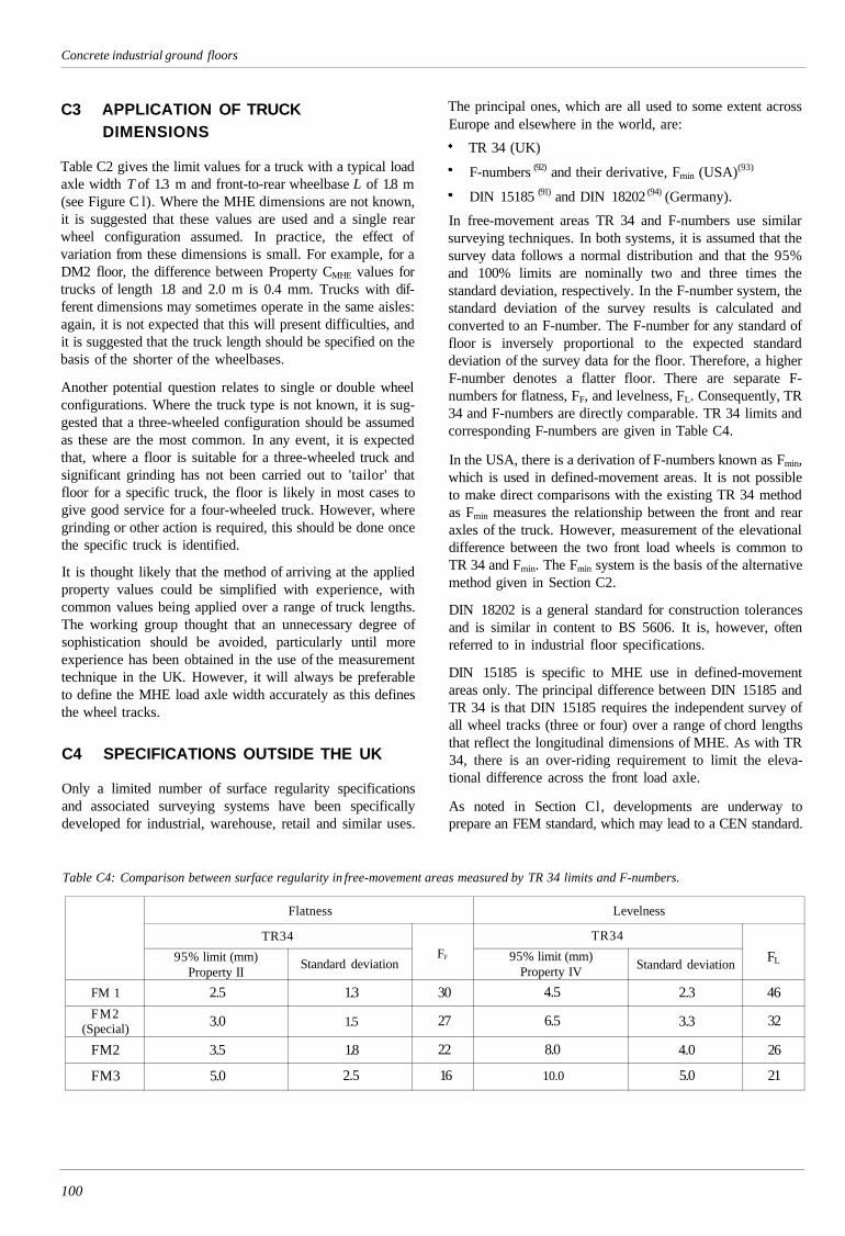
Concrete industrial ground floors
C3 APPLICATION OF TRUCKDIMENSIONS
Table C2 gives the limit values for a truck with a typical loadaxle width T of 1.3 m and front-to-rear wheelbase L of 1.8 m(see Figure C l). Where the MHE dimensions are not known,it is suggested that these values are used and a single rearwheel configuration assumed. In practice, the effect ofvariation from these dimensions is small. For example, for aDM2 floor, the difference between Property CMHE values fortrucks of length 1.8 and 2.0 m is 0.4 mm. Trucks with dif-ferent dimensions may sometimes operate in the same aisles:again, it is not expected that this will present difficulties, andit is suggested that the truck length should be specified on thebasis of the shorter of the wheelbases.
Another potential question relates to single or double wheelconfigurations. Where the truck type is not known, it is sug-gested that a three-wheeled configuration should be assumedas these are the most common. In any event, it is expectedthat, where a floor is suitable for a three-wheeled truck andsignificant grinding has not been carried out to 'tailor' thatfloor for a specific truck, the floor is likely in most cases togive good service for a four-wheeled truck. However, wheregrinding or other action is required, this should be done oncethe specific truck is identified.
It is thought likely that the method of arriving at the appliedproperty values could be simplified with experience, withcommon values being applied over a range of truck lengths.The working group thought that an unnecessary degree ofsophistication should be avoided, particularly until moreexperience has been obtained in the use of the measurementtechnique in the UK. However, it will always be preferableto define the MHE load axle width accurately as this definesthe wheel tracks.
C4 SPECIFICATIONS OUTSIDE THE UK
Only a limited number of surface regularity specificationsand associated surveying systems have been specificallydeveloped for industrial, warehouse, retail and similar uses.
The principal ones, which are all used to some extent acrossEurope and elsewhere in the world, are:
TR 34 (UK)
F-numbers (92) and their derivative, Fmin (USA)(93)
DIN 15185 (91) and DIN 18202 (94) (Germany).
In free-movement areas TR 34 and F-numbers use similarsurveying techniques. In both systems, it is assumed that thesurvey data follows a normal distribution and that the 95%and 100% limits are nominally two and three times thestandard deviation, respectively. In the F-number system, thestandard deviation of the survey results is calculated andconverted to an F-number. The F-number for any standard offloor is inversely proportional to the expected standarddeviation of the survey data for the floor. Therefore, a higherF-number denotes a flatter floor. There are separate F-numbers for flatness, FF, and levelness, FL. Consequently, TR34 and F-numbers are directly comparable. TR 34 limits andcorresponding F-numbers are given in Table C4.
In the USA, there is a derivation of F-numbers known as Fmin,which is used in defined-movement areas. It is not possibleto make direct comparisons with the existing TR 34 methodas Fmin measures the relationship between the front and rearaxles of the truck. However, measurement of the elevationaldifference between the two front load wheels is common toTR 34 and Fmin. The Fmin system is the basis of the alternativemethod given in Section C2.
DIN 18202 is a general standard for construction tolerancesand is similar in content to BS 5606. It is, however, oftenreferred to in industrial floor specifications.
DIN 15185 is specific to MHE use in defined-movementareas only. The principal difference between DIN 15185 andTR 34 is that DIN 15185 requires the independent survey ofall wheel tracks (three or four) over a range of chord lengthsthat reflect the longitudinal dimensions of MHE. As with TR34, there is an over-riding requirement to limit the eleva-tional difference across the front load axle.
As noted in Section Cl, developments are underway toprepare an FEM standard, which may lead to a CEN standard.
Table C4: Comparison between surface regularity in free-movement areas measured by TR 34 limits and F-numbers.
FM 1
FM2(Special)
FM2
FM3
Flatness
TR34
95% limit (mm)Property II
2.5
3.0
3.5
5.0
Standard deviation
1.3
1.5
1.8
2.5
FF
30
27
22
16
Levelness
TR34
95% limit (mm)Property IV
4.5
6.5
8.0
10.0
Standard deviation
2.3
3.3
4.0
5.0
FL
46
32
26
21
100
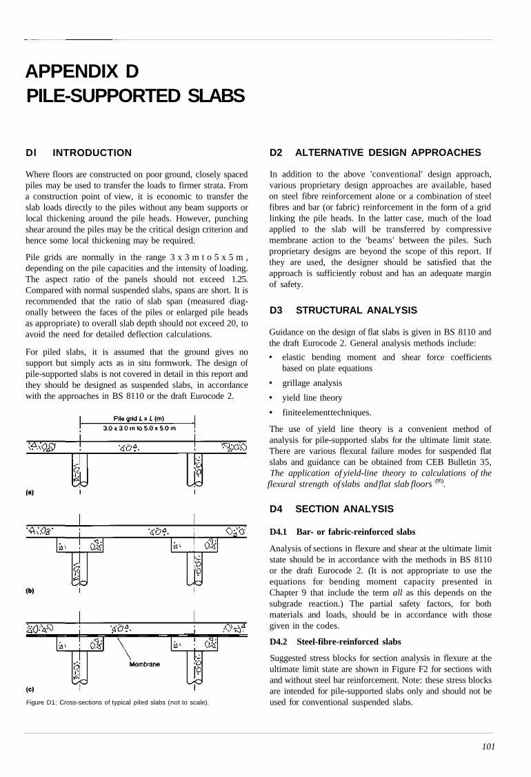
APPENDIX DPILE-SUPPORTED SLABS
Dl INTRODUCTION
Where floors are constructed on poor ground, closely spacedpiles may be used to transfer the loads to firmer strata. Froma construction point of view, it is economic to transfer theslab loads directly to the piles without any beam supports orlocal thickening around the pile heads. However, punchingshear around the piles may be the critical design criterion andhence some local thickening may be required.
Pile grids are normally in the range 3 x 3 m t o 5 x 5 m ,depending on the pile capacities and the intensity of loading.The aspect ratio of the panels should not exceed 1.25.Compared with normal suspended slabs, spans are short. It isrecommended that the ratio of slab span (measured diag-onally between the faces of the piles or enlarged pile headsas appropriate) to overall slab depth should not exceed 20, toavoid the need for detailed deflection calculations.
For piled slabs, it is assumed that the ground gives nosupport but simply acts as in situ formwork. The design ofpile-supported slabs is not covered in detail in this report andthey should be designed as suspended slabs, in accordancewith the approaches in BS 8110 or the draft Eurocode 2.
Figure D1: Cross-sections of typical piled slabs (not to scale).
D2 ALTERNATIVE DESIGN APPROACHES
In addition to the above 'conventional' design approach,various proprietary design approaches are available, basedon steel fibre reinforcement alone or a combination of steelfibres and bar (or fabric) reinforcement in the form of a gridlinking the pile heads. In the latter case, much of the loadapplied to the slab will be transferred by compressivemembrane action to the 'beams' between the piles. Suchproprietary designs are beyond the scope of this report. Ifthey are used, the designer should be satisfied that theapproach is sufficiently robust and has an adequate marginof safety.
D3 STRUCTURAL ANALYSIS
Guidance on the design of flat slabs is given in BS 8110 andthe draft Eurocode 2. General analysis methods include:
elastic bending moment and shear force coefficientsbased on plate equations
grillage analysis
yield line theory
finite element techniques.
The use of yield line theory is a convenient method ofanalysis for pile-supported slabs for the ultimate limit state.There are various flexural failure modes for suspended flatslabs and guidance can be obtained from CEB Bulletin 35,The application of yield-line theory to calculations of the
flexural strength of slabs and flat slab floors (95).
D4 SECTION ANALYSIS
D4.1 Bar- or fabric-reinforced slabs
Analysis of sections in flexure and shear at the ultimate limitstate should be in accordance with the methods in BS 8110or the draft Eurocode 2. (It is not appropriate to use theequations for bending moment capacity presented inChapter 9 that include the term all as this depends on thesubgrade reaction.) The partial safety factors, for bothmaterials and loads, should be in accordance with thosegiven in the codes.
D4.2 Steel-fibre-reinforced slabs
Suggested stress blocks for section analysis in flexure at theultimate limit state are shown in Figure F2 for sections withand without steel bar reinforcement. Note: these stress blocksare intended for pile-supported slabs only and should not beused for conventional suspended slabs.
101
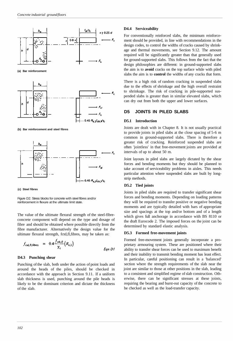
Concrete industrial ground floors
(a) Bar reinforcement
(b) Bar reinforcement and steel fibres
(c) Steel fibres
Figure D2: Stress blocks for concrete with steel fibres and/orreinforcement in flexure at the ultimate limit state.
The value of the ultimate flexural strength of the steel-fibre-concrete component will depend on the type and dosage offibre and should be obtained where possible directly from thefibre manufacturer. Alternatively the design value for theultimate flexural strength, fctd,fl,fibres, may be taken as:
D4.3 Punching shear
Punching of the slab, both under the action of point loads andaround the heads of the piles, should be checked inaccordance with the approach in Section 9.11. If a uniformslab thickness is used, punching around the pile heads islikely to be the dominant criterion and dictate the thicknessof the slab.
D4.4 Serviceability
For conventionally reinforced slabs, the minimum reinforce-ment should be provided, in line with recommendations in thedesign codes, to control the widths of cracks caused by shrink-age and thermal movements, see Section 9.12. The amountrequired will be significantly greater than that generally usedfor ground-supported slabs. This follows from the fact that thedesign philosophies are different: in ground-supported slabsthe aim is to avoid cracks on the top surface while with piledslabs the aim is to control the widths of any cracks that form.
There is a high risk of random cracking in suspended slabsdue to the effects of shrinkage and the high overall restraintto shrinkage. The risk of cracking in pile-supported sus-pended slabs is greater than in similar elevated slabs, whichcan dry out from both the upper and lower surfaces.
D5 JOINTS IN PILED SLABS
D5.1 Introduction
Joints are dealt with in Chapter 8. It is not usually practicalto provide joints in piled slabs at the close spacing of 5-6 mcommon in ground-supported slabs. There is therefore agreater risk of cracking. Reinforced suspended slabs areoften 'jointless' in that free-movement joints are provided atintervals of up to about 50 m.
Joint layouts in piled slabs are largely dictated by the shearforces and bending moments but they should be planned totake account of serviceability problems in aisles. This needsparticular attention where suspended slabs are built by long-strip methods.
D5.2 Tied joints
Joints in piled slabs are required to transfer significant shearforces and bending moments. Depending on loading patternsthey will be required to transfer positive or negative bendingmoments and are typically detailed with bars of appropriatesize and spacings at the top and/or bottom and of a lengthwhich gives full anchorage in accordance with BS 8110 orthe draft Eurocode 2. The imposed forces on the joint can bedetermined by standard elastic analysis.
D5.3 Formed free-movement joints
Formed free-movement joints generally incorporate a pro-prietary armouring system. These are positioned where theirability to transfer shear forces can be used to maximum benefitand their inability to transmit bending moment has least effect.In particular, careful positioning can result in a 'balanced'section where the strength requirements of the slab near thejoint are similar to those at other positions in the slab, leadingto a consistent and simplified regime of slab construction. Oth-erwise, there can be significant stresses at these joints,requiring the bearing and burst-out capacity of the concrete tobe checked as well as the load-transfer capacity.
102
APPENDIX EDESIGN WITH STEEL FABRIC REINFORCEMENT
El SUPPLEMENT TO CHAPTER 9,STRENGTH AND SERVICEABILITYOF SLABS
Research commissioned for this edition has examined thepotential for taking advantage of the structural enhancementprovided by the nominal areas of steel fabric commonly usedin ground-supported floors. Ductility requirements havebeen established in terms of rotation capacity and tests onbeams of typical slab depths and associated fabric areas haveconfirmed that these rotations are easily achieved. Full-scaleslab tests have confirmed that the Meyerhof analysis used inChapter 9 is appropriate for establishing load-carryingcapacity for point loads, with the positive moment capacitycalculated by conventional lever arm methods in accordancewith BS 8110 or the draft Eurocode 2. Full details of thesetests and the related research are contained in a separatereport (6).
To ensure adequate rotational capacity the positive momentcapacity M p should not exceed the negative moment capacityMn. However, it is recommended that the commonly usedsteel areas of 0.1 to 0.125% are not exceeded, as discussed inSection 8.10.2.
The positive bending moment capacity Mp is calculatedfrom:
where
area of steel
characteristic strength of steel
effective depth
partial safety factor for steel (see Section 9.6.2)
Dimensions of standard square fabrics are given in Section944
As before, the negative bending moment capacity Mn isgiven by:
Eqn 9.9
These recommendations apply to slabs reinforced with fabric(or bar reinforcement) located near the bottom surface. Slabswith fabric (or bar reinforcement) located near the topsurface only should be designed as plain concrete slabs.
E2 EXTENSION TO APPENDIX B,THICKNESS DESIGN OF AGROUND-SUPPORTED FLOOR SLAB
The design example in Appendix B is for a steel-fibre-rein-forced jointless slab. The example is extended here to afabric reinforced slab with sawn-restrained movement jointsat approximately 6 m intervals.
E2.1 Zone A: Racking - Ultimate limit state
For A142 fabric with 50 mm cover to the bottom of the slab:
125 mm
14.3 kNm/m as before
460 N/mm2
7.4 kNm/m (equivalent fibrereinforced value = 7.2 kNm/m from B3).
Internal loading
By observation, the internal capacity will be adequate. See B3.
Loading at joints
For fabric reinforcement with all
and with a/l = 0.2, Pu = 144.8 kN
For a/l = 0.148, interpolating between the two values, gives:Pu = 123.5 kN
Thus for free-edge loading Pu = 123.5 kN for A142 fabricreinforcement, which is below the required 144 kN. Thisassumes free-edge loading with the baseplates at the slabedge. If the opening of the joint is restricted, it may beassumed that 15% of the load is transferred by aggregateinterlock, reducing the required load capacity to 122.4 kN.For fabric, from Table 9.7, there would be an additional load-transfer capacity of 13.4 kN/m. This will be effective over alength of 0.9/ either side of the load (see Section 8.8.4) givinga load transfer of 13.4 x 2 x 0.67 = 18.0 kN. Thus the requiredcapacity is reduced to 122.4 - 18.0 = 104.4 kN and hence thefabric reinforced design (P = 123.5 kN) is adequate.
Check for punching at the critical perimeter (adjacent to asawn joint)
For fabric reinforcement:
d = 125 and = 550 + ( 250) = 1335 mm
From Equation 9.30, the shear capacity of fabric-reinforcedconcrete is:
103
Concrete industrial ground floors
which is less than the minimum 0.035/k3/2fck1/2 = 0.56 N/mm2
which should be used in design.
Thus the shear capacity of the fabric-reinforced concrete slabis given by:
Pp = 0.56x 1335 x 125 = 93.5 kN
Aggregate interlock and the dowelling effect of the fabricwill reduce the required load capacity. As the baseplates arespaced 250 mm apart the effective length of joint over whichload transfer will occur is increased from 0.9l either side to atotal of (2 x 0.9l) + 250 = (2 x 670) + 250 = 1590 mm. Thisresults in 13.4 x 1.59 = 21.3 kN being transferred by dow-elling, resulting in a required capacity of 122.4 - 21.3 =101.1 kN. Hence the slab is inadequate in punching at theedge.
The required capacity could be achieved by increasing theeffective depth to 135 mm (i.e. by reducing the bottom coverto the fabric to 40 mm), which would give a punching shearcapacity of 105.7 kN. Alternatively steps could be taken toensure that the baseplates are located a minimum of 70 mmfrom the edge. This would increase the punching perimeterto 1475 mm and hence the load capacity to 103.3 kN, makingthe design satisfactory.
E2.2 Materials handling equipment
By observation, the internal capacity will be adequate. SeeSection B7.
E2.3 Relative position of fork-lift truck and rackingleg
Internal loading
By observation, see Section B7, the slab is adequate forinternal loading.
Loading at joints
Initially ignore load transfer. For all = 0
Pu = [ (Mp + Mn) / 2] + 2 Mn = 62.7 kN Eqn 9.11a
and with a/l = 0.2
Pu = [ (Mp + Mn) + 4Mn]/1-2a/3l) Eqn 9.11b
= 144.8 kN
For all = 0.134, interpolating between the two values gives:
Pu= 117.7 kN
Thus for free-edge loading Pu = 117.7 kN, which is below therequired 144 kN. If the opening of the joint is restricted (seeSection 8.8), it may be assumed that 15% of the load is trans-ferred by aggregate interlock, reducing the required loadcapacity to 122.4 kN. For fabric, from Table 9.7, there willbe an additional load-transfer capacity of 13.4 kN/m. Thiswill be effective over a length of 0.9l either side of the load(see Section 8.8.4) giving a load transfer of 13.4 x 2 x 0.9 x0.744 = 17.9 kN. Thus the required capacity is reduced to122.4 - 17.9 = 104.5 kN and hence the design is adequate.
104

APPENDIX FSOURCES OF INFORMATION
Association of Concrete Industrial Flooring Contractors(ACIFC)33 Oxford Street, Leamington SpaWarwickshire CV34 4RATel: 01926 833633. Fax: 01926 423236E-mail: [email protected]: www.acifc.org.uk
British Board of Agrément (BBA)PO Box 195, Bucknalls LaneGarston, Watford, Herts WD25 9BATel: 01923 665300. Fax: 01923 665301Website: www.bbacerts.co.uk
British Cement Association (BCA)Century House, Telford AvenueCrowthorne, Berkshire RG45 6YSTel: 01344 762676. Fax: 01344 761214Email: [email protected]: www.bca.org.uk
British Industrial Truck Association (BITA)5-7 High Street, Sunninghill, Ascot, Berkshire SL5 9NQTel: 01344 623800. Fax: 01344 291197E-mail: [email protected]: www.bita.org.uk
British Standards Institution (BSI)389 Chiswick High Road, London W4 4ALTel: 020 8996 9000. Fax: 020 8996 7001E-mail: [email protected]: www.bsi-global.com
Building Research Establishment (BRE)Garston, Watford WD25 9XXTel: 01923 664000E-mail: [email protected]: www.bre.co.uk
Construction Industry Research and Information Association(CIRIA)6 Storey's Gate, London SW1P 3AUTel: 020 7222 8891. Fax: 020 7222 1708E-mail: [email protected]: www.ciria.org.uk
Cement Admixtures Association (CAA)38a Tilehouse Green Lane, Knowle, West Midlands B93 9EYTel: 01564 776362. Fax: 01564 776362Website: www.admixtures.org.uk
The Concrete SocietyCentury House, Telford AvenueCrowthorne, Berkshire RG45 6YSTel: 01344 466007. Fax: 01344 466008E-mail: [email protected]: www.concrete.org.uk
Federation Européenne de la Manutention(European Federation of Materials Handling and StorageEquipment)c/o Orgalime, Diamant Building, 80 Boulevard A. ReyersB-1030 Brussels, BelgiumTel: 2-706 82 35. Fax: 2-706 82 50E-mail: [email protected]: www.fem-eur.com/
International Association for Cold Storage ConstructionEuropean DivisionDownmill Road, Bracknell, Berkshire RG12 1GHTel: 01144 01344 869533. Fax: 01344 869527Website: www.iascs.org
Loughborough UniversityDepartment of Civil and Building EngineeringLoughborough UniversityLoughborough, Leicestershire LEU 3TUTel: 01509 222884. Fax: 01509 223981E-mail: [email protected]: www.lboro.ac.uk/departments/cv
Packaging and Industrial Films Association (PIFA)2 Mayfair Court, North Gate, Nottingham NG7 7GRTel: 0115 942 2445. Fax: 0115 942 2650E-mail: [email protected]: www.pifa.co.uk
Storage Equipment Manufacturers' Association (SEMA)6th Floor, The McLaren Building35 Dale End, Birmingham B4 7LNTel: 0121 200 2100. Fax: 0121 200 1306Website: www.sema.org.uk
UK CARESPembroke House, 21 Pembroke RoadSevenoaks, Kent TNI3 1XRTel: 01732 450000. Fax: 01732 455917E-mail: [email protected]: www.ukcares.com
United Kingdom Warehousing Association (UKWA)Walter House, 418-22 Strand, London WC2R OPTTel: 0207 836 5522/0449. Fax: 0207 379 6904E-mail: [email protected]: www.ikwa.org.uk
UK Slip Resistance Group (UKSRG)RAPRA Technology LtdShawbury, Shropshire SY4 4NRTel: 01939 250383Website: www.rapra.net
105
SPONSOR PROFILES
The companies featured on the following pages sponsored the project to develop this edition of Technical Report34. The Society is pleased to have the opportunity to feature their specialist expertise and services in this sectionof the report.
Previous pageis blank
SPONSORSAssociation of Concrete Industrial FlooringContractors (ACIFC)
ABS Brvmar Floors Ltd
A J Clark Concrete Flooring LtdBekaert Building Products Ltd
BRC
Cement Admixtures Association
Combined Floor Services
Don Construction Products LtdFace Consultants LtdFibercon UK
Fosseway Flooring Systems Ltd
Gomaco International Ltd
John Pyatt Concreting LtdKent Wire (ISPAT) Ltd
Mike Amodeo (Contractors) Ltd
Permaban Products Ltd
Precision Concrete Floors
Ready-mixed Concrete Bureau(Note: The Ready-mixed Concrete-Bureau ischanging its function and operation In 2003 and so adetailed profile is not included in the followng pages.)
ROM Ltd
Rinol Silidur
Sika Armorex
Snowden Flooring Ltd
Somero Enterprises Ltd
Stanford Industrial Concrete Flooring Ltd
Stuarts Industrial Flooring Ltd
Synthetic Industries
Twintec Industrial Flooring Ltd
107
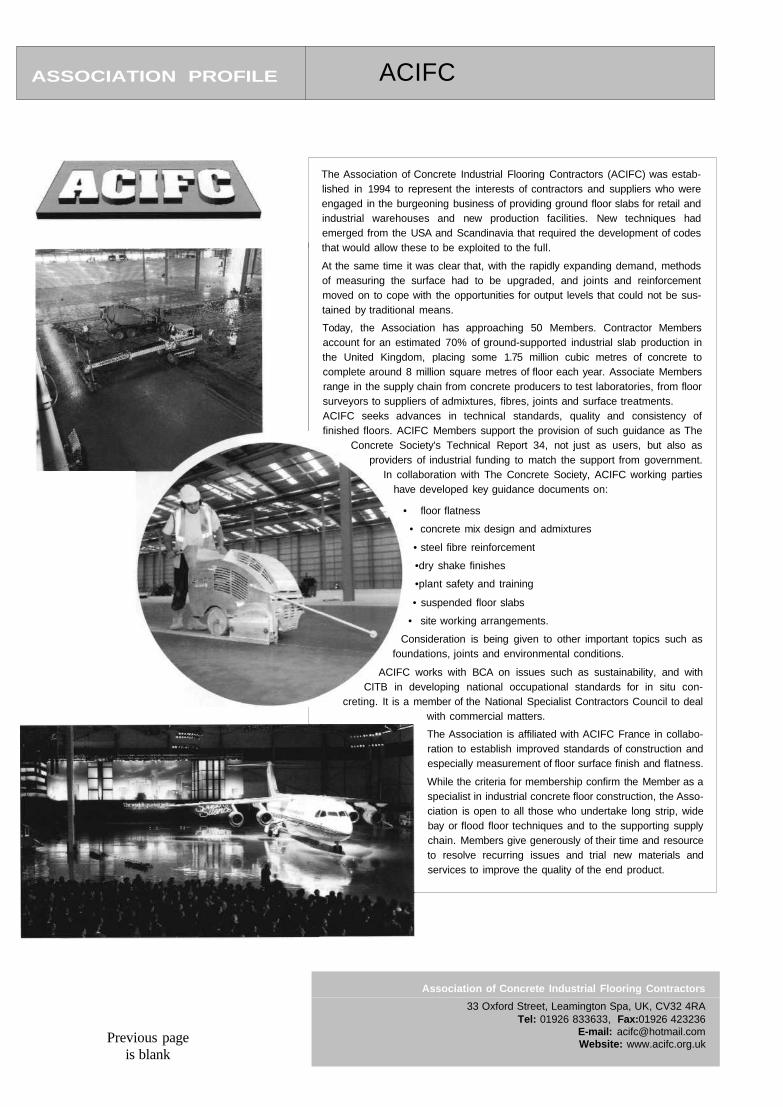
ASSOCIATION PROFILE ACIFC
The Association of Concrete Industrial Flooring Contractors (ACIFC) was estab-lished in 1994 to represent the interests of contractors and suppliers who wereengaged in the burgeoning business of providing ground floor slabs for retail andindustrial warehouses and new production facilities. New techniques hademerged from the USA and Scandinavia that required the development of codesthat would allow these to be exploited to the full.
At the same time it was clear that, with the rapidly expanding demand, methodsof measuring the surface had to be upgraded, and joints and reinforcementmoved on to cope with the opportunities for output levels that could not be sus-tained by traditional means.
Today, the Association has approaching 50 Members. Contractor Membersaccount for an estimated 70% of ground-supported industrial slab production inthe United Kingdom, placing some 1.75 million cubic metres of concrete tocomplete around 8 million square metres of floor each year. Associate Membersrange in the supply chain from concrete producers to test laboratories, from floorsurveyors to suppliers of admixtures, fibres, joints and surface treatments.ACIFC seeks advances in technical standards, quality and consistency offinished floors. ACIFC Members support the provision of such guidance as The
Concrete Society's Technical Report 34, not just as users, but also asproviders of industrial funding to match the support from government.
In collaboration with The Concrete Society, ACIFC working partieshave developed key guidance documents on:
• floor flatness
• concrete mix design and admixtures
• steel fibre reinforcement
•dry shake finishes
•plant safety and training
• suspended floor slabs
• site working arrangements.
Consideration is being given to other important topics such asfoundations, joints and environmental conditions.
ACIFC works with BCA on issues such as sustainability, and withCITB in developing national occupational standards for in situ con-
creting. It is a member of the National Specialist Contractors Council to dealwith commercial matters.
The Association is affiliated with ACIFC France in collabo-ration to establish improved standards of construction andespecially measurement of floor surface finish and flatness.
While the criteria for membership confirm the Member as aspecialist in industrial concrete floor construction, the Asso-ciation is open to all those who undertake long strip, widebay or flood floor techniques and to the supporting supplychain. Members give generously of their time and resourceto resolve recurring issues and trial new materials andservices to improve the quality of the end product.
Previous pageis blank
Association of Concrete Industrial Flooring Contractors
Tel: 01926 833633, Fax:01926 423236E-mail: [email protected]: www.acifc.org.uk
33 Oxford Street, Leamington Spa, UK, CV32 4RA
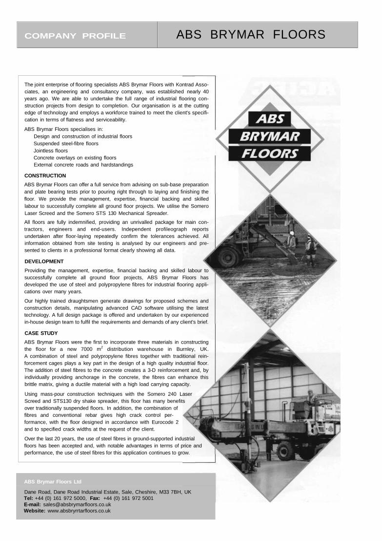
The joint enterprise of flooring specialists ABS Brymar Floors with Kontrad Asso-ciates, an engineering and consultancy company, was established nearly 40years ago. We are able to undertake the full range of industrial flooring con-struction projects from design to completion. Our organisation is at the cuttingedge of technology and employs a workforce trained to meet the client's specifi-cation in terms of flatness and serviceability.
ABS Brymar Floors specialises in:Design and construction of industrial floorsSuspended steel-fibre floorsJointless floorsConcrete overlays on existing floorsExternal concrete roads and hardstandings
CONSTRUCTION
ABS Brymar Floors can offer a full service from advising on sub-base preparationand plate bearing tests prior to pouring right through to laying and finishing thefloor. We provide the management, expertise, financial backing and skilledlabour to successfully complete all ground floor projects. We utilise the SomeroLaser Screed and the Somero STS 130 Mechanical Spreader.
All floors are fully indemnified, providing an unrivalled package for main con-tractors, engineers and end-users. Independent profileograph reportsundertaken after floor-laying repeatedly confirm the tolerances achieved. Allinformation obtained from site testing is analysed by our engineers and pre-sented to clients in a professional format clearly showing all data.
DEVELOPMENT
Providing the management, expertise, financial backing and skilled labour tosuccessfully complete all ground floor projects, ABS Brymar Floors hasdeveloped the use of steel and polypropylene fibres for industrial flooring appli-cations over many years.
Our highly trained draughtsmen generate drawings for proposed schemes andconstruction details, manipulating advanced CAD software utilising the latesttechnology. A full design package is offered and undertaken by our experiencedin-house design team to fulfil the requirements and demands of any client's brief.
CASE STUDY
ABS Brymar Floors were the first to incorporate three materials in constructingthe floor for a new 7000 m2 distribution warehouse in Burnley, UK.A combination of steel and polypropylene fibres together with traditional rein-forcement cages plays a key part in the design of a high quality industrial floor.The addition of steel fibres to the concrete creates a 3-D reinforcement and, byindividually providing anchorage in the concrete, the fibres can enhance thisbrittle matrix, giving a ductile material with a high load carrying capacity.
Using mass-pour construction techniques with the Somero 240 LaserScreed and STS130 dry shake spreader, this floor has many benefitsover traditionally suspended floors. In addition, the combination offibres and conventional rebar gives high crack control per-formance, with the floor designed in accordance with Eurocode 2and to specified crack widths at the request of the client.
Over the last 20 years, the use of steel fibres in ground-supported industrialfloors has been accepted and, with notable advantages in terms of price andperformance, the use of steel fibres for this application continues to grow.
COMPANY PROFILE ABS BRYMAR FLOORS
ABS Brymar Floors Ltd
Dane Road, Dane Road Industrial Estate, Sale, Cheshire, M33 7BH, UKTel: +44 (0) 161 972 5000, Fax: +44 (0) 161 972 5001E-mail: [email protected]: www.absbryrrtarfloors.co.uk
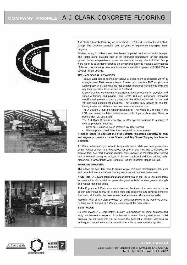
COMPANY PROFILE A J CLARK CONCRETE FLOORING
A J Clark Flooring Ltd
Clark House, High Glencairn Street, Kilmamock KA1 4AB, UKTel: 01563 539993 Fax: 01563 570197
A J Clark Concrete Flooring was launched in 1996 and is part of the A J ClarkGroup. The Directors combine over 20 years of experience managing majorprojects.
To date, every A J Clark project has been completed on time and within budget.This factor alone provides one of the strongest foundations for our plannedgrowth. In an independent construction customer survey, the A J Clark Groupwere reported to be demonstrating an exceptional ability to manage every aspectof the job, coordinating men, machines and materials in projects of £100,000 toseveral million pounds.
TECHNOLOGICAL ADVANCESToday's laser screed technology allows a skilled team to complete 20 m2 ina single pass. That means a team of seven can complete 2000 m2 plus in aworking day. A J Clark was the first Scottish registered company to own andregularly operate a laser screed in Scotland.Laser screeding consistently out-performs hand screeding for precision andspeed of flooring and paving. Lower costs, reduced manpower, increasedmobility and greater accuracy guarantee the skilled teams will be 'on' and'off' site with exceptional efficiency. This creates early access for the fol-lowing trades and delivers improved customer satisfaction.The A J Clark Group are regular delegates at 'The World of Concrete' in theUSA, and deliver the latest initiatives and technology, such as steel fibres, tobenefit their UK customers.The A J Clark Group is also able to offer optimal solutions to a range ofdiverse problems, such as:- Steel fibre jointless pours installed by laser screed- Pile-supported steel fibre floors installed by laser screed.
It makes sense to contract the first Scottish registered company to ownand regularly operate a Laser Screed and Dry Shake Topping Machine inScotland.
A J Clark understands you want to keep costs down, while you need guaranteesof the highest quality - and that access for other trades must not be delayed. Toachieve this, A J Clark Flooring division have invested in the latest laser screedand automated paving technology. In addition traditional and flood pouring tech-niques are in accordance with Concrete Society Technical Report No. 34.
WORKING SMARTER
This allows the A J Clark team to create for you minimum maintenance, flat, leveland durable internal concrete flooring and external concrete pavements.
A UK First - A J Clark could shout about being first in the UK to use steel fibresin conjunction with a slipform paver designed to 'build in' ever greater strengthand reduce concrete costs.
Rolls Royce - A J Clark were commissioned by Amec, the main contractor, todesign and install 48,000 m2 of steel fibre pile-supported and jointless concretefloor slab, all installed by laser screed and automated dry shake spreader.
Results - With all A J Clark projects, UK-wide, completed in the last three years,on time and to budget, A J Clark's results speak for themselves.
BEST VALUE
So what makes A J Clark better? Simply, our approach to doing business andearly involvement of experts. Experienced in major flooring design and buildprojects, we will work with you to ensure the best value solution. Advising ontechniques that will save you cost and time, without compromising quality.
COMPANY PROFILE BEKAERT
Bekaert Building Products
PO Box 119, Shepcote Lane, Sheffield S9 1TY, UKTel: +44 (0) 114 2244 487, Fax: +44 (0) 114 22 44 564E-mail: [email protected]: www.bekaert.com/building
Bekaert is a technology-driven business that produces and markets a wide rangeof products based on metal transformation and coating technologies. The Group'sactivities are built around four business units: Wire, Merchant Products, SteelCord, and Bekaert Advanced Materials.
Bekaert has grown from a small manufacturing and trading company, founded byLeo Leander Bekaert in 1880, into a global group with its head office in Belgium.Starting in Western Europe, the group moved into North America and LatinAmerica and has been expanding rapidly in Asia in recent years. Bekaert now has96 production centres in 29 countries and an extensive network of sales offices andagencies, employing around 17,500 people.
Bekaert Building Products are based in Sheffield, and entered the UK industrialflooring market with their steel wire fibre, Dramix®, in 1990. Produced by the colddrawing process, which increases the tensile strength of the wire and guaranteesits length and diameter, Dramix® fibres give the complete concrete reinforcementsolution. Providing excellent anchorage through its distinctive hooked end,Dramix® can enhance the concrete's properties in terms of crack control,increasing load-carrying capacity, and improving impact and fatigue resistance.
Sold into industrial flooring globally for over 30 years, the main advantages of usingDramix® are the time savings achieved by the removal of traditional reinforcement,the possibility of 'jointless' floors, the reduction of traditional bar in conventionalpiled floor solutions, and potential savings in overall construction costs.
FLOORING APPLICATIONS
Traditional jointed floors: By replacing traditional steel fabric reinforcementwith Dramix® steel fibres, overall material costs are reduced and the con-struction process is simplified.
'Jointless' floors: Using laser screed technology, large area panels free ofinternal stress-relieving joints can be constructed due to the enhanced crack-distribution characteristics of the high length/diameter ratio Dramix® fibres.Piled floors: Bekaert's patented piled floor system, combining Dramix® steelfibres and traditional steel cages, designed in accordance with Eurocode 2,minimises steel fixing time and increases productivity.External yards: Set-up time can be reduced by the absence of steel mesh,whilst increasing impact and fatigue resistance to heavily trafficked areas.
NEW! Multi-storey decking: By replacing mesh withDramix® and utilising the Ward Multideck 60 profiledmetal deck, construction advantages include:
time and concrete volumesavings
ease of constructionreduced materials storage requiredsimplified transport of materials to theconstruction facereduced trip hazards due to the removal ofmesh.
With proven 1.0 and 1.5-hour fire ratings, through work at Warrington FireResearch and technical support by the SCI, multi-storey and mezzanineapplications can be catered for.
Linking all of these technical benefits with our free, fully indemnified design service,and the use of specialist flooring contractors, you have a fast and very efficientflooring programme with a high-quality, high-performance steel fibre concrete.
East MidlandsBRC MansfieldTel: 01623 555111Fax: 01623 440932Email:[email protected]
SouthBRC SouthamptonTel: 01794 521158
Fax: 01794 521154Email:[email protected]
NorthBRC BarnsleyTel: 01226 730330Fax: 01226 771797Email:sales® north. brc. ltd. u k
South EastBRC LondonTe): 020 7474 1800Fax: 020 7474 8686Email:[email protected]
North EastBRC DarlingtonTel: 01325 381166Fax: 01325 284124Email:[email protected]. ltd. uk
South WestBRC PlymouthTel: 01752 894660Fax: 01752 896761Email:[email protected]. u k
North WestBRC OldhamTel: 0161 620 1001Fax: 0161 620 1660Email:[email protected]
Wales and WestBRC NewportTel: 01633 244002Fax: 01633 265643Email:[email protected]
ScotlandBRC NewhouseTel: 01698 732343Fax: 01698 833894Email:[email protected]
West MidlandsBRC BirminghamTel: 0121 327 0049Fax: 0121 327 2574Email:[email protected]
WWW.BRC-UK.CO.UK
After almost a century as a major manufacturer and distributor of steel rein-forcement, BRC are committed and experienced in offering the best combinationof quality, price, service and availability.In recent years, we have absorbed other leading companies such as SpencerMesh and Square Grip, and this growth, together with the 'partnership' approachwe take towards our customers, has been a key factor in our ability to serve achanging industry. We continue to evolve and develop so that we are always ableto meet the demands placed upon us.With a view to further improve our service, we are continually introducing newproducts. Recent developments include gas protection membranes - for whichwe offer a design, supply and sub-contract service - all supported by BBA certi-fication and a full installation guarantee.Speed of construction is always important. We work closely with our customersto provide solutions ranging from prefabricated bar to non-standard fabrics andbespoke accessories. We also work closely with customers to facilitate the elec-tronic transfer of information - including 'SteelPac', a suite of products ensuringseamless data transfer across the entire supply chain from design consultants tothe reinforcement suppliers.Members of our team have worked on construction sites and appreciate andunderstand the pressures and demands that have to be met by our customers.This empathy enables us to offer suitable solutions to speed construction orassist with temporary skills shortages.Standard fabric, flying end fabric and specially designed meshes are produced atour two manufacturing plants in the North and South of England, along with ourcircular spacers and continuous high chairs. The positioning of these two fabricproduction units ensures quick and reliable distribution throughout mainland UK.We believe that our products, from bar and fabric to wire spacers and other con-struction accessories, and our services, including prefabrication and contractordetailing, are unequalled in the market.Having recognised the need for quality assurance throughout our ranges, ourcompany is BS EN ISO 9002 and CARES-approved, and we play a leading rolein setting product standards within the industry.BRC have a nationwide network of strategically located regional businesses, allstaffed by people who take pride in our ability to meet the needs of our cus-tomers, from the smallest orders to the largest, most prestigious projects, and weare committed to providing our customers with real value for money, whether toa local builder or to a major flooring contractor or civil engineering organisation.As part of the global Acertec Group, BRC also have divisions specialising in wallreinforcement and insulation (BRC Building Products), tunnelling and groundstabilisation (BRC Weldgrip), and permanent formwork and precast concreteaccessories (BRC Special Products).
COMPANY PROFILE B R C
COMPANY PROFILE CEMENT ADMIXTURES ASSOCIATION
The Cement Admixtures Association (CAA) is a trade association founded in the United Kingdom in1963 to promote and support the effective use of admixtures in concrete, mortar and grout.
Full membership is open to companies who manufacture or supply admixtures for use with hydrauliccement and who have traded in this sector for at least two years. Full members must operate a thirdparty certified quality management system complying with ISO 9001 or ISO 9002, and meet therequirements of the new European Admixture Standard EN 934. They are also required to provide acomprehensive level of technical advice and support.
The CAA provides documented technical information sheets on admixtures and their storage, dis-pensing, use and environmental impact. Information sheets are also available on admixture selectionand use for industrial ground floors. The CAA is pleased to provide help to users through trainingcourses and by giving talks and lectures on admixtures and admixture related subjects.
The Association's full members include all the major companies involved in the development, manu-facture and supply of admixtures in the United Kingdom. Several of these companies also have majoroverseas involvement in admixtures.
the Sign of Quality
Cementaid (UK) Ltd2 Rutherford Way Industrial Estate, Crawley, West Sussex, RH10 2PBTel: 01293 447 878 Fax: 01293 447 880 www.cementaid.com
Christeyns UK LtdRutland St, Bradford, West Yorkshire, BD4 7EATel: 01274 393 286 Fax: 01274 309 143 www.christeyns.com
Fosroc LtdColeshill Rd, Faseley, Tamworth, Staffs B78 3TLTel: 01827 262 222 Fax: 01827 262 444 www.fosrocuk.com
Grace Construction Products Ltd852 Birchwood Boulevard, Birchwood, Warrington, Cheshire WA3 7QZTel: 01925 824 824 Fax: 01925 824 033 www.graceconstruction.com
Master BuildarsTechnologies
MBT FEB MBT AdmixturesAlbany House, Swinton Hall Rd, Swinton, Manchester M27 1DTTel: 0161 727 2727 Fax: 0161 727 8547 www.mbtfeb.co.uk
RMC Group PLCRMC House, Coldharbour Lane, Thorp, Egham, Surrey TW20 8TDTel: 01932 568 833 Fax: 01923 568 933 www.rmc-group.com
Sika LtdWatchmead, Welwyn Garden City, Herts AL7 1BQTel: 01707 394 444 Fax: 01707 329 129 www.sika.com
Cement Admixtures Association
38a Tilehouse Green Lane, Knowle, West Midlands B93 9EY, UKTel/Fax + 44 (0) 1564 776362E-mail: [email protected] Website: www.admixtures.org.ukContact: John M. Dransfieid BSc, FCS
ASSOCIATE MEMBERSBalmoral MouldingsElkem Materials LtdSynthomer Ltd
Borregaard UK LtdClarient UK LtdFosroc International Ltd
COMPANY PROFILE COMBINED FLOORING SERVICES
Combined Flooring Services Ltd
99 Lakewood Road, Chandlers Ford, Eastieigh, Hampshire SO53 5AD, UKTel: 02380 262017 Fax: 02380 276162
E-mail: [email protected]: www.ftoorsurvey.com
One of the UK's longest established providers of design, consultation and mea-surement of industrial concrete floors, Combined Flooring Services offerswide-ranging services to cover the many operational requirements of commercialand industrial concrete floors. These services range from advising engineers,mechanical handling equipment suppliers and floor users on the right floorflatness specification to providing guidance and advice to the contractorsinvolved.Every floor requirement is special and different. Users therefore have an infinitelywide variation of floor surface and flatness requirements. While the choice ofspecification is paramount for the end user in terms of capital and operationalcosting as well as long-term use, getting it right from the outset has to be the aim.Getting it right first time will not only save floor users a significant amount ofmoney in the short term, but can result in a decreased potential risk of remedialworks in later years of use.However, floor specification is not always so simple, as initial requirementschosen by a developer do not always meet floor users' needs.Our case histories have shown that many clients do not need to aspire to ultrahigh tolerance floors (Superflat or even Category 1), as applications and levelsof use do not require that level of precision.Many of our clients need additional space that may mean using the full height ofthe building for storage. In these situations Combined Flooring Services willadvise on the most appropriate specification. This allows clients to seek moreeconomical floors that suit their specific requirements. For many years this hasbeen the fundamental and common sense approach of Combined Flooring,whose client base includes many worldwide 'blue chip' companies.
SERVICES
Floor surveys: Offering floor surveys to establish compliance to TheConcrete Society Technical Report 34 tolerances for defined and free-movement surveys. We may use a floor profileograph, floor scanner orindeed the F-min rig used for the Alternative Measuring System proposed inthis latest revision of TR34.Floor grinding: Floor grinding should only be carried out as a last resort andwhen deemed necessary to meet the floor user's specific requirements. Thiscan occur in areas of defined traffic where floor tolerances can be critical forthe safe operation of VNA trucks. In these situations Combined FlooringServices will carry out grinding services to meet critical tolerances.Consultancy services: We believe in a policy of full preparation prior to con-struction. Determining the correct floor design for the application and thecorrect method of construction is a vital component of the project, where ourexpertise is invaluable. Supervising the floor as it is constructed is also vitalin ensuring that the specified tolerances are achieved. Regular feedback tothe contractor allows any required adjustments to be made immediately.
Combined Flooring Services works worldwide to help in the installation of high-quality, fitness-assured floors in France, Germany, Belgium, Spain, Holland,Brazil, Canada, USA, Japan and Singapore, providing a fast response and quickfeedback from highly skilled teams. Engineers, floor users, developers and manyof the UK's specialist contractors rely on this service.At Combined Flooring Services, our overriding interest is delivering the best,most economic solution, whoever or wherever our client is.
COMPANY PROFILE DON CONSTRUCTION PRODUCTS
Don Construction Products Ltd
Churnetside Business Park, Station Road Cheddleton, Leek,Staffordshire ST13 7RS, UKTel: 01538 361799 Fax: 01538 361899E-mail: [email protected]: www.donconstruction.co.ukContact: Lesley Clarke
Don Construction Products Ltd was founded over 65 years ago and is a long-established UK manufacturer within the construction chemicals market. Our ISO9001-accredited site in Staffordshire offers state-of-the-art manufacturing facilities.
Specialising in reactive chemical technology, DCP manufacture a comprehensiverange of products, including resin and cementitious concrete repair materials, pro-tective coatings, structural grouts and adhesives, waterproofing products and awide range of concrete admixtures.
DCP also produce one of the largest ranges of flooring solutions by a single man-ufacturer in the UK today, used in industrial and commercial applications. Therange comprises epoxy and polyurethane resin coatings and toppings offeringseamless, hygienic, chemical-resistant surfaces with improved abrasion andimpact resistance, available in a wide range of colours.
A cementitious pump-applied industrial wearing coat and basecoat system ispurpose-designed for the refurbishment of existing internal floors - a fast-tracksystem allowing up to 2000 m2 to be applied in one day.
Dry shake flooring systems, spearheaded by TIBMIX, offer the ultimate per-formance for any new-build project requiring a hardwearing, low maintenance,cost-effective floor, available in a standard range of colours.
All the above are suitable for use in a wide range of applications, particularly areasfor production, food processing, warehousing and distribution.
GRIPDECK is a solvent-free polyurethane car park decking system. Offering ahighly durable, protective and flexible waterproof membrane, GRIPDECK not onlyimproves the appearance of the structure, but also provides on-going protectionagainst the perils of weathering, carbonation and contaminants.
Cementitious repair mortars offer a complete system solution to cater for small andlarge-scale concrete repair problems. Using migrating corrosion inhibitor tech-nology, the mortar contains an inhibitor that actively seeks and is absorbed ontothe steel layer in reinforced concrete, forming a protective layer and stoppingfurther corrosion and subsequent damage to surrounding concrete. Resin repairmaterials are designed for specialised repairs where excellent mechanical prop-erties, chemical protection and dynamic loading are key considerations.
Our product range is targeted at the industrial construction and civil engineeringmarkets for both new-build and refurbishment projects, the synergy betweenindustrial and commercial build being common.
Operating nationally throughout the UK, a team of technical sales managersis readily available to offer advice and guidance on product suitability for agiven application to clients, specifiers and contractors. This is backed upby a dedicated in-house technical team who are constantly looking atways of improving product performance and testing new applicationsdemanded by the market place.
Product training and application in the range of products is availablelocally or at the company's fully equipped training school at the HeadOffice. Technical seminars can be provided accompanied by practicaldemonstrations geared to the particular area of interest by thecustomer.
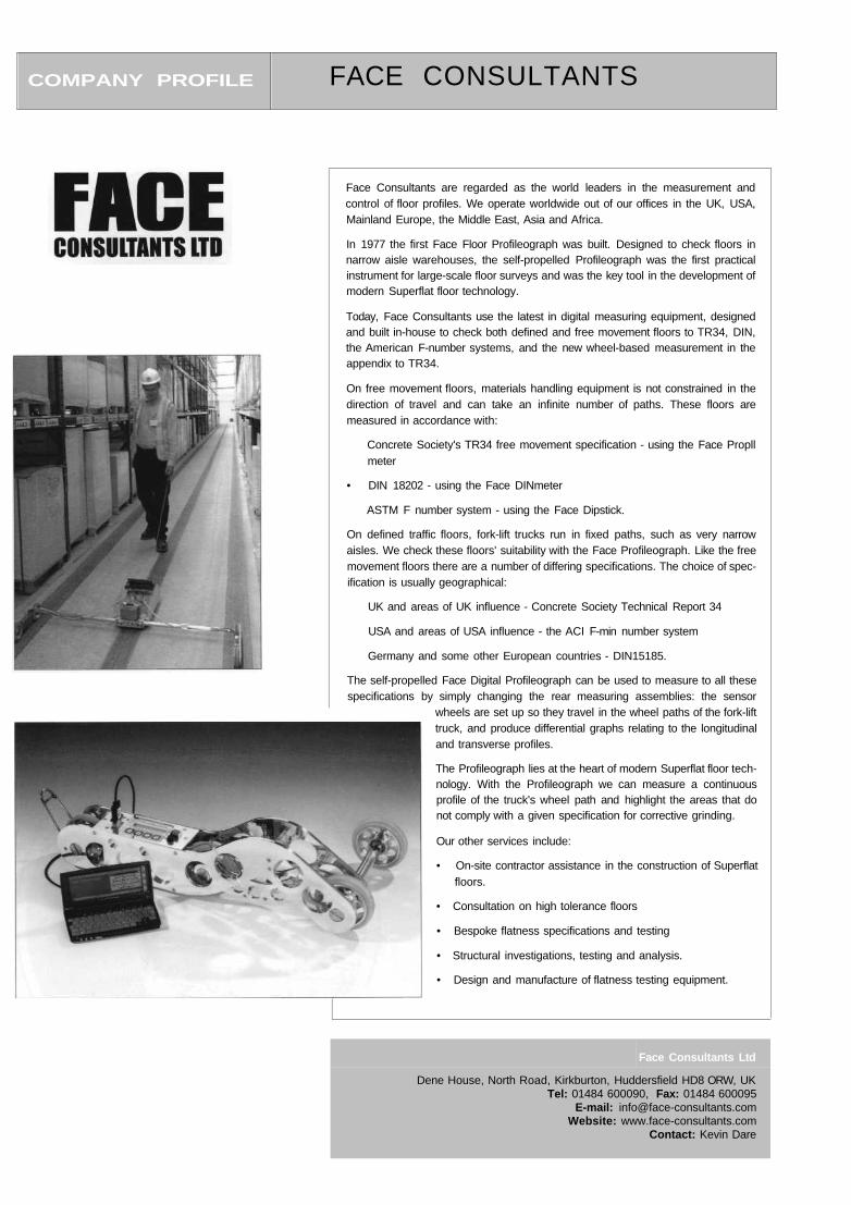
COMPANY PROFILE FACE CONSULTANTS
Face Consultants Ltd
Dene House, North Road, Kirkburton, Huddersfield HD8 ORW, UKTel: 01484 600090, Fax: 01484 600095
E-mail: [email protected]: www.face-consultants.com
Contact: Kevin Dare
Face Consultants are regarded as the world leaders in the measurement andcontrol of floor profiles. We operate worldwide out of our offices in the UK, USA,Mainland Europe, the Middle East, Asia and Africa.
In 1977 the first Face Floor Profileograph was built. Designed to check floors innarrow aisle warehouses, the self-propelled Profileograph was the first practicalinstrument for large-scale floor surveys and was the key tool in the development ofmodern Superflat floor technology.
Today, Face Consultants use the latest in digital measuring equipment, designedand built in-house to check both defined and free movement floors to TR34, DIN,the American F-number systems, and the new wheel-based measurement in theappendix to TR34.
On free movement floors, materials handling equipment is not constrained in thedirection of travel and can take an infinite number of paths. These floors aremeasured in accordance with:
Concrete Society's TR34 free movement specification - using the Face Propllmeter
• DIN 18202 - using the Face DINmeter
ASTM F number system - using the Face Dipstick.
On defined traffic floors, fork-lift trucks run in fixed paths, such as very narrowaisles. We check these floors' suitability with the Face Profileograph. Like the freemovement floors there are a number of differing specifications. The choice of spec-ification is usually geographical:
UK and areas of UK influence - Concrete Society Technical Report 34
USA and areas of USA influence - the ACI F-min number system
Germany and some other European countries - DIN15185.
The self-propelled Face Digital Profileograph can be used to measure to all thesespecifications by simply changing the rear measuring assemblies: the sensor
wheels are set up so they travel in the wheel paths of the fork-lifttruck, and produce differential graphs relating to the longitudinaland transverse profiles.
The Profileograph lies at the heart of modern Superflat floor tech-nology. With the Profileograph we can measure a continuousprofile of the truck's wheel path and highlight the areas that donot comply with a given specification for corrective grinding.
Our other services include:
• On-site contractor assistance in the construction of Superflatfloors.
• Consultation on high tolerance floors
• Bespoke flatness specifications and testing
• Structural investigations, testing and analysis.
• Design and manufacture of flatness testing equipment.
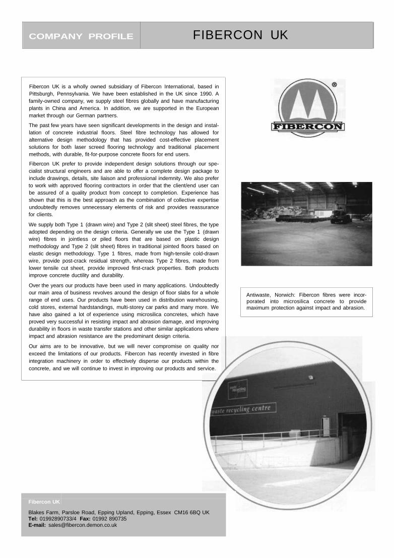
COMPANY PROFILE FIBERCON UK
Fibercon UK
Blakes Farm, Parsloe Road, Epping Upland, Epping, Essex CM16 6BQ UKTel: 01992890733/4 Fax: 01992 890735E-mail: [email protected]
Fibercon UK is a wholly owned subsidiary of Fibercon International, based inPittsburgh, Pennsylvania. We have been established in the UK since 1990. Afamily-owned company, we supply steel fibres globally and have manufacturingplants in China and America. In addition, we are supported in the Europeanmarket through our German partners.
The past few years have seen significant developments in the design and instal-lation of concrete industrial floors. Steel fibre technology has allowed foralternative design methodology that has provided cost-effective placementsolutions for both laser screed flooring technology and traditional placementmethods, with durable, fit-for-purpose concrete floors for end users.
Fibercon UK prefer to provide independent design solutions through our spe-cialist structural engineers and are able to offer a complete design package toinclude drawings, details, site liaison and professional indemnity. We also preferto work with approved flooring contractors in order that the client/end user canbe assured of a quality product from concept to completion. Experience hasshown that this is the best approach as the combination of collective expertiseundoubtedly removes unnecessary elements of risk and provides reassurancefor clients.
We supply both Type 1 (drawn wire) and Type 2 (slit sheet) steel fibres, the typeadopted depending on the design criteria. Generally we use the Type 1 (drawnwire) fibres in jointless or piled floors that are based on plastic designmethodology and Type 2 (slit sheet) fibres in traditional jointed floors based onelastic design methodology. Type 1 fibres, made from high-tensile cold-drawnwire, provide post-crack residual strength, whereas Type 2 fibres, made fromlower tensile cut sheet, provide improved first-crack properties. Both productsimprove concrete ductility and durability.
Over the years our products have been used in many applications. Undoubtedlyour main area of business revolves around the design of floor slabs for a wholerange of end uses. Our products have been used in distribution warehousing,cold stores, external hardstandings, multi-storey car parks and many more. Wehave also gained a lot of experience using microsilica concretes, which haveproved very successful in resisting impact and abrasion damage, and improvingdurability in floors in waste transfer stations and other similar applications whereimpact and abrasion resistance are the predominant design criteria.
Our aims are to be innovative, but we will never compromise on quality norexceed the limitations of our products. Fibercon has recently invested in fibreintegration machinery in order to effectively disperse our products within theconcrete, and we will continue to invest in improving our products and service.
Antiwaste, Norwich: Fibercon fibres were incor-porated into microsilica concrete to providemaximum protection against impact and abrasion.
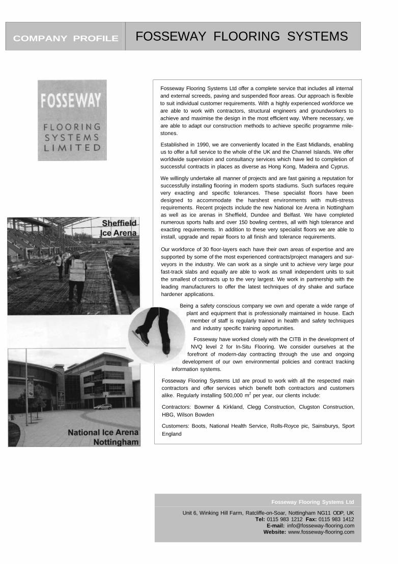
COMPANY PROFILE FOSSEWAY FLOORING SYSTEMS
Fosseway Flooring Systems Ltd
Unit 6, Winking Hill Farm, Ratcliffe-on-Soar, Nottingham NG11 ODP, UKTel: 0115 983 1212 Fax: 0115 983 1412
E-mail: [email protected]: www.fosseway-flooring.com
Fosseway Flooring Systems Ltd offer a complete service that includes all internaland external screeds, paving and suspended floor areas. Our approach is flexibleto suit individual customer requirements. With a highly experienced workforce weare able to work with contractors, structural engineers and groundworkers toachieve and maximise the design in the most efficient way. Where necessary, weare able to adapt our construction methods to achieve specific programme mile-stones.
Established in 1990, we are conveniently located in the East Midlands, enablingus to offer a full service to the whole of the UK and the Channel Islands. We offerworldwide supervision and consultancy services which have led to completion ofsuccessful contracts in places as diverse as Hong Kong, Madeira and Cyprus.
We willingly undertake all manner of projects and are fast gaining a reputation forsuccessfully installing flooring in modern sports stadiums. Such surfaces requirevery exacting and specific tolerances. These specialist floors have beendesigned to accommodate the harshest environments with multi-stressrequirements. Recent projects include the new National Ice Arena in Nottinghamas well as ice arenas in Sheffield, Dundee and Belfast. We have completednumerous sports halls and over 150 bowling centres, all with high tolerance andexacting requirements. In addition to these very specialist floors we are able toinstall, upgrade and repair floors to all finish and tolerance requirements.
Our workforce of 30 floor-layers each have their own areas of expertise and aresupported by some of the most experienced contracts/project managers and sur-veyors in the industry. We can work as a single unit to achieve very large pourfast-track slabs and equally are able to work as small independent units to suitthe smallest of contracts up to the very largest. We work in partnership with theleading manufacturers to offer the latest techniques of dry shake and surfacehardener applications.
Fosseway Flooring Systems Ltd are proud to work with all the respected maincontractors and offer services which benefit both contractors and customersalike. Regularly installing 500,000 m2 per year, our clients include:
Contractors: Bowmer & Kirkland, Clegg Construction, Clugston Construction,HBG, Wilson Bowden
Customers: Boots, National Health Service, Rolls-Royce pic, Sainsburys, Sport
England
Being a safety conscious company we own and operate a wide range ofplant and equipment that is professionally maintained in house. Each
member of staff is regularly trained in health and safety techniquesand industry specific training opportunities.
Fosseway have worked closely with the CITB in the development ofNVQ level 2 for In-Situ Flooring. We consider ourselves at the
forefront of modern-day contracting through the use and ongoingdevelopment of our own environmental policies and contract tracking
information systems.
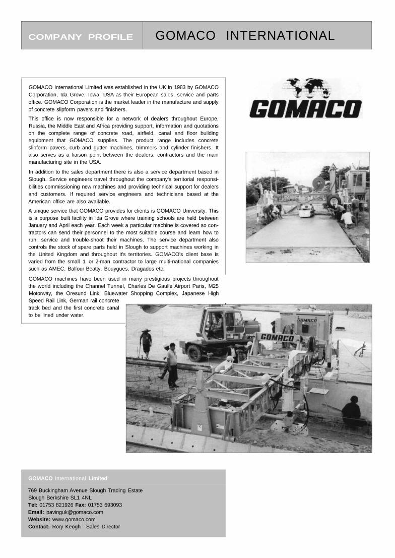
COMPANY PROFILE GOMACO INTERNATIONAL
GOMACO International Limited
769 Buckingham Avenue Slough Trading EstateSlough Berkshire SL1 4NLTel: 01753 821926 Fax: 01753 693093Email: [email protected]: www.gomaco.comContact: Rory Keogh - Sales Director
GOMACO International Limited was established in the UK in 1983 by GOMACOCorporation, Ida Grove, Iowa, USA as their European sales, service and partsoffice. GOMACO Corporation is the market leader in the manufacture and supplyof concrete slipform pavers and finishers.
This office is now responsible for a network of dealers throughout Europe,Russia, the Middle East and Africa providing support, information and quotationson the complete range of concrete road, airfield, canal and floor buildingequipment that GOMACO supplies. The product range includes concreteslipform pavers, curb and gutter machines, trimmers and cylinder finishers. Italso serves as a liaison point between the dealers, contractors and the mainmanufacturing site in the USA.
In addition to the sales department there is also a service department based inSlough. Service engineers travel throughout the company's territorial responsi-bilities commissioning new machines and providing technical support for dealersand customers. If required service engineers and technicians based at theAmerican office are also available.
A unique service that GOMACO provides for clients is GOMACO University. Thisis a purpose built facility in Ida Grove where training schools are held betweenJanuary and April each year. Each week a particular machine is covered so con-tractors can send their personnel to the most suitable course and learn how torun, service and trouble-shoot their machines. The service department alsocontrols the stock of spare parts held in Slough to support machines working inthe United Kingdom and throughout it's territories. GOMACO's client base isvaried from the small 1 or 2-man contractor to large multi-national companiessuch as AMEC, Balfour Beatty, Bouygues, Dragados etc.
GOMACO machines have been used in many prestigious projects throughoutthe world including the Channel Tunnel, Charles De Gaulle Airport Paris, M25Motorway, the Oresund Link, Bluewater Shopping Complex, Japanese HighSpeed Rail Link, German rail concretetrack bed and the first concrete canalto be lined under water.
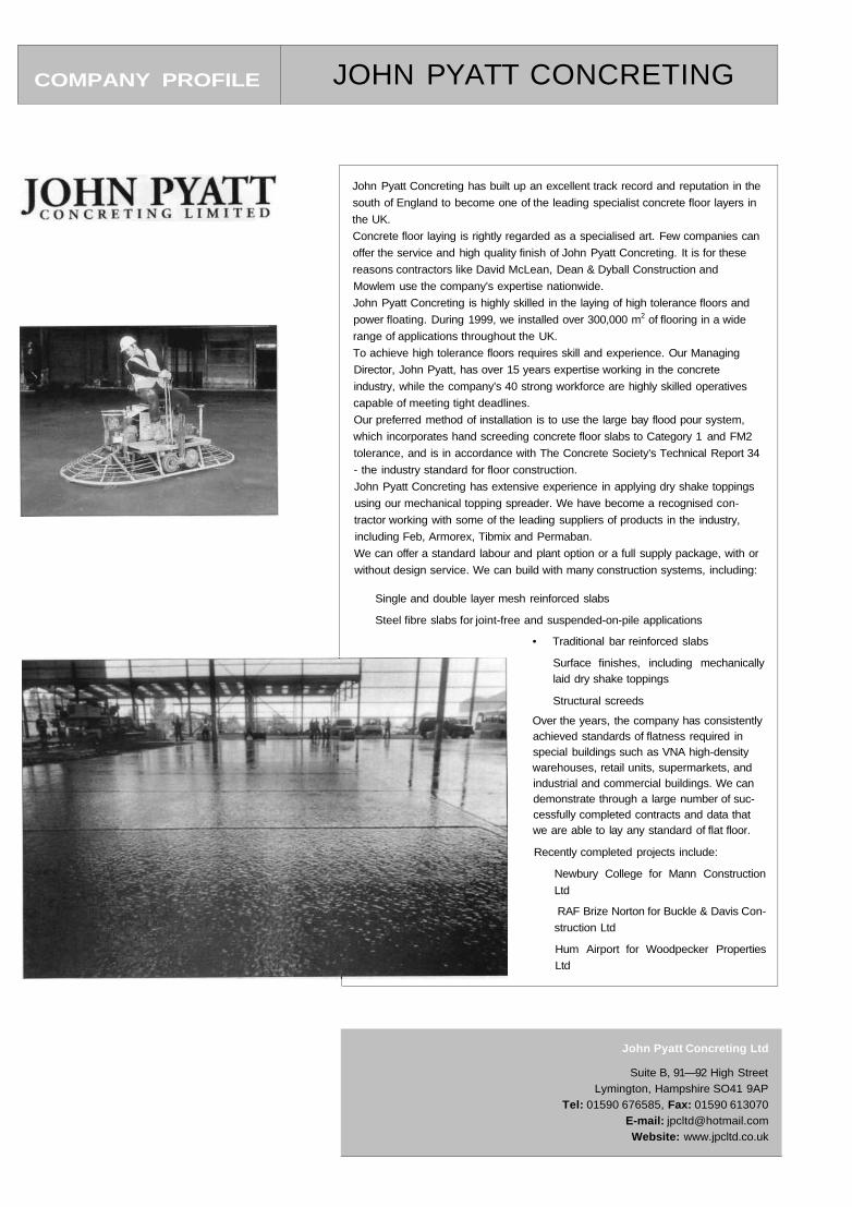
COMPANY PROFILE JOHN PYATT CONCRETING
• Traditional bar reinforced slabs
Surface finishes, including mechanicallylaid dry shake toppings
Structural screeds
Over the years, the company has consistentlyachieved standards of flatness required inspecial buildings such as VNA high-densitywarehouses, retail units, supermarkets, andindustrial and commercial buildings. We candemonstrate through a large number of suc-cessfully completed contracts and data thatwe are able to lay any standard of flat floor.
Recently completed projects include:
Newbury College for Mann Construction
Ltd
RAF Brize Norton for Buckle & Davis Con-
struction Ltd
Hum Airport for Woodpecker Properties
Ltd
John Pyatt Concreting has built up an excellent track record and reputation in the
south of England to become one of the leading specialist concrete floor layers in
the UK.
Concrete floor laying is rightly regarded as a specialised art. Few companies can
offer the service and high quality finish of John Pyatt Concreting. It is for these
reasons contractors like David McLean, Dean & Dyball Construction and
Mowlem use the company's expertise nationwide.
John Pyatt Concreting is highly skilled in the laying of high tolerance floors and
power floating. During 1999, we installed over 300,000 m2 of flooring in a wide
range of applications throughout the UK.
To achieve high tolerance floors requires skill and experience. Our Managing
Director, John Pyatt, has over 15 years expertise working in the concrete
industry, while the company's 40 strong workforce are highly skilled operatives
capable of meeting tight deadlines.
Our preferred method of installation is to use the large bay flood pour system,
which incorporates hand screeding concrete floor slabs to Category 1 and FM2
tolerance, and is in accordance with The Concrete Society's Technical Report 34
- the industry standard for floor construction.
John Pyatt Concreting has extensive experience in applying dry shake toppings
using our mechanical topping spreader. We have become a recognised con-
tractor working with some of the leading suppliers of products in the industry,
including Feb, Armorex, Tibmix and Permaban.
We can offer a standard labour and plant option or a full supply package, with or
without design service. We can build with many construction systems, including:
Single and double layer mesh reinforced slabs
Steel fibre slabs for joint-free and suspended-on-pile applications
John Pyatt Concreting Ltd
Suite B, 91—92 High StreetLymington, Hampshire SO41 9AP
Tel: 01590 676585, Fax: 01590 613070E-mail: [email protected]: www.jpcltd.co.uk
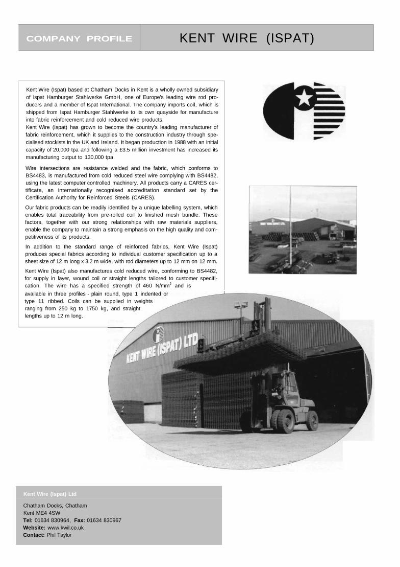
COMPANY PROFILE KENT WIRE (ISPAT)
Kent Wire (Ispat) Ltd
Chatham Docks, ChathamKent ME4 4SWTel: 01634 830964, Fax: 01634 830967Website: www.kwil.co.ukContact: Phil Taylor
Kent Wire (Ispat) based at Chatham Docks in Kent is a wholly owned subsidiaryof Ispat Hamburger Stahlwerke GmbH, one of Europe's leading wire rod pro-ducers and a member of Ispat International. The company imports coil, which isshipped from Ispat Hamburger Stahlwerke to its own quayside for manufactureinto fabric reinforcement and cold reduced wire products.Kent Wire (Ispat) has grown to become the country's leading manufacturer offabric reinforcement, which it supplies to the construction industry through spe-cialised stockists in the UK and Ireland. It began production in 1988 with an initialcapacity of 20,000 tpa and following a £3.5 million investment has increased itsmanufacturing output to 130,000 tpa.
Wire intersections are resistance welded and the fabric, which conforms toBS4483, is manufactured from cold reduced steel wire complying with BS4482,using the latest computer controlled machinery. All products carry a CARES cer-tificate, an internationally recognised accreditation standard set by theCertification Authority for Reinforced Steels (CARES).
Our fabric products can be readily identified by a unique labelling system, whichenables total traceability from pre-rolled coil to finished mesh bundle. Thesefactors, together with our strong relationships with raw materials suppliers,enable the company to maintain a strong emphasis on the high quality and com-petitiveness of its products.
In addition to the standard range of reinforced fabrics, Kent Wire (Ispat)produces special fabrics according to individual customer specification up to asheet size of 12 m long x 3.2 m wide, with rod diameters up to 12 mm on 12 mm.
Kent Wire (Ispat) also manufactures cold reduced wire, conforming to BS4482,for supply in layer, wound coil or straight lengths tailored to customer specifi-cation. The wire has a specified strength of 460 N/mm2 and is
available in three profiles - plain round, type 1 indented ortype 11 ribbed. Coils can be supplied in weightsranging from 250 kg to 1750 kg, and straightlengths up to 12 m long.
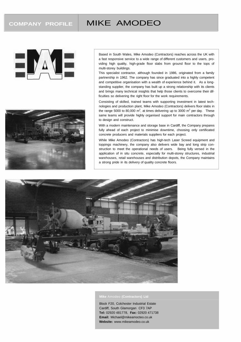
COMPANY PROFILE MIKE AMODEO
Mike Amodeo (Contractors) Ltd
Block F20, Colchester Industrial EstateCardiff, South Glamorgan CF3 7APTel: 02920 481778, Fax: 02920 471738Email: [email protected]: www.mikeamodeo.co.uk
Based in South Wales, Mike Amodeo (Contractors) reaches across the UK witha fast responsive service to a wide range of different customers and users, pro-viding high quality, high-grade floor slabs from ground floor to the tops ofmulti-storey buildings.This specialist contractor, although founded in 1986, originated from a familypartnership in 1962. The company has since graduated into a highly competentand competitive organisation with a wealth of experience behind it. As a long-standing supplier, the company has built up a strong relationship with its clientsand brings many technical insights that help those clients to overcome their dif-ficulties so delivering the right floor for the work requirements.
Consisting of skilled, trained teams with supporting investment in latest tech-nologies and production plant, Mike Amodeo (Contractors) delivers floor slabs inthe range 5000 to 80,000 m2, at times delivering up to 3000 m2 per day. Thesesame teams will provide highly organised support for main contractors throughto design and construct.
With a modern maintenance and storage base in Cardiff, the Company preparesfully ahead of each project to minimise downtime, choosing only certificatedconcrete producers and materials suppliers for each project.
While Mike Amodeo (Contractors) has high-tech Laser Screed equipment andtoppings machinery, the company also delivers wide bay and long strip con-struction to meet the operational needs of users. Being fully versed in theapplication of in situ concrete, especially for multi-storey structures, industrialwarehouses, retail warehouses and distribution depots, the Company maintainsa strong pride in its delivery of quality concrete floors.
COMPANY PROFILE PERMABAN
Permaban specialises in developing new solutions and providing design advice,products and services for concrete floors.
JOINT ARRIS ARMOURING AND LOAD TRANSFER
Free contraction joints (construction joints) are the parts of a floor which breakdown most frequently. This is recognised in BS 8204: Part 2: 1999. Section 8.5,which requires the designer to consider steel section joint formers for free con-traction joints to protect them from damage in heavy duty situations.
Permaban has developed the AlphaJoint system, which armours the joint arrisedges with two 10x50mm steel strips. It incorporates the Diamond or Alpha PlateDowel giving exceptional load transfer with 2-plane joint movement, i.e. normaljoint opening and differential lateral movement between adjacent slabs.
Alpha Joint is self-supported, requires no welding, is quick and easy to level andprovides a 60 mm lap between 3 m lengths ensureing a straight joint line. Concretecan be placed on both sides of the joint on the same day. Prefabricated corner, T-junction and four-way intersections are also available.
This development is a product of Permaban's metal processing technology, engi-neering design capability and in-depth understanding of concrete floors.Recognition in the market place has been strong and sustained with Alpha Jointreceiving the 2002 SED Award for Innovation in Concrete.
The AlphaJoint is backed up by a full range of floor slab ancillary productsincluding: Permasteel leave-in-place formwork system; StripJoint joint arrisarmouring and load transfer system for use with timber forms; Permaseal/Per-mathane concrete curing and floor sealing products; and Permaflex joint sealingand joint arris repair systems.
SPECIALIST FLOORING SYSTEMS
Permashake Dry Shake coloured concrete floor hardeners provide attractive,maintenance free, low cost floors which can be constructed rapidly (e.g. 100,000ft2 retail warehouses in 5 days with 3 days drying period).
Permaban's Contracting Division has its own teams of qualified installers, providingnationwide coverage for installation of:
Resin coatings, screeds, flow-coats and epoxy terrazzoPolymer modified screeds including pumpable, self-levelling and fast-set repairmortars (including cementitious terrazzo)
• Composite flooring
Our clients include all the major retail DIY chains, Warehouse and LogisticsDevelopers and Operators, Food and Pharmaceutical industry, MOD, Engineering,General Construction etc.
FLOOR REPAIRS
Our advice is often requested when a change of use is anticipated or if problemshave arisen with existing concrete floors. The contracting division is well equippedand skilled to provide a complete service and offer:
Concrete floor repair solutionsFloor flatness tolerance reinstatementJoint repair and arris armouringSurface abrasion improvementFloor maintenance programmes
Permaban have been pleased to sponsor this revision of TR34 and assist in itspreparation. We continue to develop and innovate in order to remain a leader inimproving the performance and appearance of concrete floors.
Permaban Limited
Mill Close, Lee Mill Industrial Estate, Ivybridge, Devon, PL21 9GL, UKTel : 01752 895288 Fax: 01752 690535E-mail: [email protected]: www.permaban.com
COMPANY PROFILE PRECISION CONCRETE FLOORS
Precision Concrete Floors
Suite 1B, Solent View, Marchwood Industrial Park, Normandy Way,Southanpton, Hampshire, SO40 4PB, UK
Tel: 02380 666400 Fax: 02380 666900E-mail: [email protected]: www.precisionconcretefloors.co.uk
P r e c i s i o n C o n c r e t e F l o o r s
Precision Concrete Floors offer the complete design, supply and installation ofnew, industrial concrete floors.The range of services we offer comprise laser screed and hand screeding,superflat floors, suspended floors, upper decks, post-tensioned floors, compositefloors, structural screeds and coloured dry shake toppings.Operating throughout the UK for over 10 years, PCF specialise in the productionof specially strengthened concrete floors with ultra-durable surfaces. Such floorsare essential in modern warehouses, distribution centres, industrial premises, fac-tories and retail outlets - in fact, in any situation where the concrete floor is subjectto continuous foot or wheeled traffic or heavy loads.
The most hardwearing of all industrial floor surfaces are those containing dry shaketoppings. These are quartz, mineral or metallic particles that are sprinkled onto thesurface of the wet concrete slab, forming a monolithic surface. Dry shake floorsurfaces are generally more durable than high strength concrete and providemaximum resistance to continuous abrasion, chemicals, oil and grease, are easyto clean, and are dustproof. Most dry shake products are available in a range ofcolours and, with special treatment, can be made slip-resistant.
PCF regularly install approximately one million square metres of concrete flooreach year, covering a wide range of design, thickness and slab type. The companyhas invested in the very latest precision equipment including S-240 Laser Screeds,STS-130 Topping Spreaders and a laser-controlled D5M Caterpillar Track Dozer.PCF can now take full responsibility for the preparation of the sub-base andachieve the necessary accuracy required for large bay operations. Using this up-to-date equipment allows up to 4000 m2 of concrete floor to be laid each day. Eachproject is guided by the experienced PCF design and technical team and backedup by directly employed teams of factory-trained operatives.PCF are the sole UK installers of the unique SILIDUR steel fibre jointless flooringsystem. By incorporating special steel fibres to reinforce the concrete, floor slabs
of up to 5000 m2 can be laid without the need for
joints. The steel fibre system is now used exten-sively to replace conventional rebar forsuspended floors on piles. The flood pour andLaser Screed process dramatically decreasestime over the old rebar system, yet maintains theflatness and accuracy that are demanded byCategory 1 tolerance floors.
A large proportion of PCF's work involves the useof the now respected nominally reinforced floor,which incorporates A142 (bottom) mesh, recom-mended in The Concrete Society's TR34 since itsintroduction in the late 1980s.
PCF look forward to meeting new challenges inthe future and meeting the criteria for flatnessand design approaches contained within the newTR34.
Their systems of work allow PCF to install floorsfor virtually any application, working to the finesttolerances and specifications.
COMPANY PROFILE RINOLSILIDUR
Silidur (UK) Limited
Ivy House, 23 South BarBanbury, Oxon 0X16 9AFUKTel: +44 (0) 1295 265200Fax: +44 (0) 1295 272084E-mail: [email protected]: www.silidur.com
Silidur (Ireland) Limited
13 Glenview HeightsMullingar, Co. WestmeathIreland
Tel:+353 (0)44 47147Fax: +353 (0) 44 84961E-mail: [email protected]
No. 1 in industrial flooring
Silidur was founded in Belgium in 1973 and in the late 1970s was the first company toproduce steel-fibre-reinforced concrete floors on a commercial scale.
Silidur (UK) Ltd was established in 1996 and has quickly built a reputation as the spe-cialist in joint-free steel-fibre-reinforced concrete floors whether on grade or on piles.
In 2001, Silidur became a member of the Rinol Group. Established in Germany in 1956,and now listed on the Frankfurt stock market, Rinol is the largest European flooring spe-cialist, and the only company to provide a complete flooring package from just onesource. From sub-base preparation to 'jointless' concrete floors with in-house dry shakehardeners or resin coatings, with Rinol, you have got it ALL IN ONE!
BENEFITS OF THE SILIDUR JOINT-FREE' CONCRETE FLOORS REINFORCEDWITH STEEL FIBRES
• In-house design
• In-house steel fibres: Eurosteel®, Twincone®, Twinplate®
• In-house Blastmachine to mix fibres evenly onsite
• On-site mobile laboratory for concrete qualitycontrol
• Can be installed on ground or on piles withoutany additional traditional reinforcement
• Jointless areas from 1000 up to 4000 m2
• Development of in-house load transfermetallic contraction-day joint, the Delta® joint
• Can meet UK, US, German and Dutchflatness specifications
• No saw-cut joints = less maintenance, more flexibility, more productivity,long-term flatness
BENEFITS OF RINOLROC SURFACE HARDENERS
• Very cost-effective
• 5 grades of hardeners formulated to meet client's individual wear requirements
• Very hard-wearing, slip-resistant and non-dusting
• Available in a range of colours
BENEFITS OF RINOL RESIN COATINGS
• Resistant to almost all aggressive chemicals
• Meet EU hygiene requirements
• Very hard-wearing, impact- and thermal-shock resistant
• Very easy to clean and maintain
• Available in a range of colours
Whatever our clients require, and wherever in the world, at Rinol, wecan provide it all from one single source. No split responsibility!
Our client list is the testimony to the quality and service of our Group:Aldi, Argos, Bestway Cash & Carry, B&Q, Big Yellow, Big W, BMW,Ford Motors, Gazeley Properties, Homebase, Ikea, Interbrew, ProLogis,Rolls Royce, Royal Mail, Tate Modern, TDG, Tesco, Wilkinson...
COMPANY PROFILE ROM
Rom LimitedI
Eastern Avenue, Trent Valley, Lichfield, Staffordshire WS13 6RN, UKTel: 01543 421680, Fax: 01543 421672
Website: www.rom.co.uk
ROM is a reinforcement specialist within the construction industry with a nationalnetwork of manufacturing and distribution plants.
Formed as a limited company in 1926 by the Newman family and based on the
River Rom, Rom River traded as a steel reinforcement company. In 1968 Rugby
Cement Group PLC bought the company, which they ran until 1997 when a man-
agement buyout took place, supported by 3l's and Lloyds Development Capital.
With a young board of directors, ROM has progressed from strength to strength
with a turnover now in excess of £50 million for ROM Ltd and £8 million for
RomTech, a sister subsidiary company specialising in piling. We have a
workforce of around 330 people, 50% of whom have been in service for over 20
years.
Supplying projects such as roads, bridges, housing, industrial units, airports,
hospitals, offices, schools, water treatment works and many more, ROM offer a
full range of services. Apart from our standard range of reinforcement products,
we also offer full technical support including:
• Prefabrication into pile caps, beams, columns etc
• Loose rebar conversion to special fabric
• Standard to tailor-made fabric
• Full range of associated accessories
• The revolutionary 'Beamform' permanent shuttering system
• Temporary fencing
Existing clients include O'Rourke, McAlpine, Carillion, Costain Skanska Mowlem,
Barratt, Kier, Laing, McLeans, Norwest Hoist, Balfour Beatty, Stent, Amec and
many more.
At ROM we pride ourselves on continually striving to improve the skills within theorganisation and therefore the service provided
to our customers.
Lichfield fabric manufacturing plant.
Fabric, prefabricated cages, ring spacers, Beamform
COMPANY PROFILE SIKA ARMOREX
Sika Limited
Watchmead, Welwyn Garden City, Herts AL7 1BQTel: 01707 394444, Fax: 01707 329129E-mail: [email protected]: www.sika.comContacts: Laurence McLennan - Sates & Marketing Manager, New ConstructionAlex Dennis - Sales & Marketing Manager, Sika-Armorex Flooring
Sika Ltd, established in 1927, is the British registered subsidiary of the Sika Group,which has a global turnover of £1 billion. We manufacture and supply specialistconstruction chemicals, including systems for the improvement and protection ofconcrete industrial floors.
The range of fully compatible Sika systems incorporates advanced concreteadmixtures, including polycarboxylate, melamine and naphthalene-based super-plasticisers, to improve placement and increase early and ultimate strengths.Performance-proven additives are complemented by polypropylene fibres, forshrinkage control and fire resistance, and steel fibres as replacements for meshreinforcement in jointless floors and for the provision of abrasion resistance.
Newly placed concrete floors can be further improved through the use of Sika fibre-suppressant compounds or the leading quartz, synthetic or metal-based dry shakehardeners and low-odour curing and sealing solutions. Benefits include additionalmechanical, impact and chemicalresistance together with dustproofing,integral colouring and increased dura-bility. A wide range of products such ascementitious pumped screeds, epoxyresin mortars and coatings, andpolyurethane joint sealants supports thecore material systems produced forindustrial wearing surfaces.
Sika Armorex is registered to ISO9001/EN29001 for quality control and toISO 14001 for environmental man-agement. Wherever appropriate,materials conform to European andBritish Standards and possess BritishBoard of Agrement certification. As anactive member of The Concrete Society,ACIFC and FeRFA the company is com-mitted to providing a professional service
from project appraisal, specification advice through to on-site support, in order toensure the success of its systems for concrete industrial floors.
Sika Ltd, global leader and your single source choice for...
• Concrete admixtures
• Fibres for concrete
• Liquid hardeners
• Dry shake hardeners
• Curing compounds
• Jointing systems
• Coatings and toppings
• Roofing membranes
COMPANY PROFILE SNOWDEN FLOORING
Snowden Flooring Ltd
Unit 1, Green Lane Industrial Park, Green Lane, Featherstone,West Yorkshire WF7 6EL, UK
Tel: 01977 696050, Fax: 01977 695051E-mail: [email protected]
Contact: Mr Pat Snowden
Founded in the 1980s, Snowden Flooring Ltd is a nationwide floor-laying con-tractor that now lays in excess of 500,000 m2 of floors per year. Moving quicklyto a position at the forefront of the floor-laying sector, the company has played aleading role in the introduction and establishment of the new Laser Screed tech-nology that has revolutionised concrete flooring construction. The SnowdenFlooring plant fleet now includes three Laser Screeds, a dry shake toppingspreader, and D5 laser-guided dozer.
Snowden Flooring now concentrates its business on full supply, design-and-buildprojects. Large, medium-to-high specification laser-screeded floors form the coreof the company's work, and floors of up to 50,000 m2 have been completed forsuch clients as B&Q, Homebase, Wincanton, Scottish & Newcastle Breweries,and Toyota.
The company employs a workforce of up to 55 trained and skilled floor-layingspecialists, many of who have been with the company for a decade. Site super-vision and control are provided by a hierarchy of site engineers and foremen,thereby ensuring that each aspect of the construction process is strictly mon-itored, and that the company's over-riding commitment to producing a quality endproduct is achieved.
The company has recently moved into new purpose-built premises in Feath-erstone, West Yorkshire. Conveniently situated for the M62 and M1, the sitecontains offices for estimating, operations and accounts, and a 1000 m2
warehouse for plant maintenance and materials storage. This relocation reflectsboth the company's sustained success, and its continuing commitment to greaterefficiency.
For a flooring contractor with a modern, professional approach, combined with afriendly and personal service, choose Snowden Flooring.
F L O O R I N G L T D
Laser ScreedCONCRETE FLOORING SPECIALISTS
COMPANY PROFILE SOMERO ENTERPRISES
Somero Enterprises Ltd
Broombank Road, Chesterfield Trading Estate, Chesterfield,Derbyshire S41 9QJ, UKTel: 01246 454455, Fax: 01246 261673E-mail: [email protected]: www.somero.comContact: Andrew Keen - Sates Director
Of all the inventions over the last 20 years, the one that has arguably revolu-tionised concrete floor construction most is the Laser Screed. First sketched asan idea in 1983, today there are in excess of 1200 machines in use in over 30countries. Combined, they are responsible for screeding in excess of 100 millionsquare metres of concrete a year.
Now owned by the multi-billion dollar Dover Corporation, Somero Enterprises hasits headquarters in Jaffrey, New Hampshire, USA. In addition to our manufac-turing facility in Houghton, Michigan, Somero maintains its European sales officeand support centre in Chesterfield, UK.
The original S-240 Laser Screed is now employed in a range of machines to suitthe individual contractor's needs. Mounted on a four-wheel-drive all-wheel-steerchassis is a rotating upper platform with a telescopic boom supporting the screedhead assembly. Using a laser transmitter as a reference source, two receiversmounted on each end of the screed head coupled with the machine's on-board automatic control system allow the concrete to be cut andscreeded to a constant and precise level.
In 1993, the first Somero STS Topping Spreader joined the LaserScreed. This finally allowed the accurate application of dry shaketoppings. Combined, these machines now form the foundation ofmodern concrete industrial floor construction.
Our innovation continues with the recent introduction of a walk-behind laser-guided screed - the CopperHead. Designed for thesmaller floor and difficult to access areas, the benefits of mech-anised large bay construction are now available on any size ofjob.
E N T E R P R I S E S
COMPANY PROFILE STANFORD INDUSTRIAL CONCRETE FLOORING
Stanford Industrial Concrete Flooring Ltd
5 Richmond Street South, West Bromwich, West Midlands B70 ODGTel: 0121 522 2220 Fax: 0121 522 2020
E-mail: [email protected]: www.stanford-flooring.co.uk
Contact: Kevin Louch - Technical Director [email protected] Brough - Senior Estimator [email protected]
Stanford is a key provider in the design and construction of high-quality concretefloor slabs both in the UK and overseas. Innovation, design and constructionexcellence, added to top quality management and total commitment to each andevery project, are the hallmarks of our reputation.Founded in 1982, Stanford today provides industrial concrete floors for ware-housing, retail and distribution facilities including high flatness tolerance andpile-supported applications. A key proponent for the adoption of increased per-formance standards combined with unique techniques and working practices hasensured that we provide competitive high quality floors to programme.Stanford can provide the full range of flooring types including:• Steel-fibre-reinforced concrete (SFRC) construction
Pile-supported slabsJoint-free poursNominally reinforced jointed slabs
Steel fabric and/or traditional bar reinforced construction- Pile-supported slabs- Nominally jointed slabsAutomated application dry shake topping flooring systems
Coloured architectural systemsFibre suppression properties
Laser screed high quality, high output techniquesFM2 and FM2 (special) tolerancesCat 1 VNA flooring system
We have constructed these flooring systems for clients such as Adidas, AGR,Argos, ASDA, Aston Martin, B&Q, BAe Airbus, Big W, Brake Bros, Bridgestone,David Lloyd Fitness Centres, Fed Ex, Focus DIY, Ford, GAP, Gillette, Hayes Dis-tribution, Healthcare Logistics, Honda, JJB Sports, Land Rover, Lidl, Makro,Matalan, MFI, Pilkington, Poundland, ProLogis, Royal Mail, Sainsbury's,Somerfield, TDG Logistics, Tesco, Tibbett & Britten, TK Maxx, Toyota, Vauxhall andVolvo Trucks.Stanford uses up-to-date technology and the best products available to design andconstruct floor slabs. This includes dry shake topping materials, steel arris pro-tection jointing systems, plate dowel load transfer systems and specialist gasmembrane and venting schemes. Each sector of the project can be tailored tomeet specific client requirements or specification.With all construction, on site quality is paramount. Recognising this, we provide aprofessional team both at pre-award and during construction. All construction ismanaged and supervised by experienced personnel responsible for quality, healthand safety and the efficient running of the project. In fact, many senior man-agement positions within Stanford are held by personnel with significant siteexperience who are fully aware of the requirements on site for a high qualityproject.Working with partners abroad Stanford is also equipped to provide the high levelof quality and efficiency in construction and project management expected in theUK, overseas. Stanford can provide the full design & build service to clients withprojects from Ireland to Asia using experienced UK labour and UK constructiontechniques, making high quality floors possible in all global facilities.
COMPANY PROFILE STUARTS INDUSTRIAL FLOORING
Stuarts Industrial Flooring Ltd
Trinity Road, Kingsbury LinkTamworth, StaffordshireB78 2EX, UKTel: 01827 871140 Fax: 01827 871155E-mail: [email protected]
Scotland Office
Stuart House, Dryden ValeBilston Glen, LoanheadMidlothian EH20 9HN, ScotlandTel: 0131 440 4000 Fax: 0131 440 2772E-mail: [email protected]
Website: www.stuarts-flooring.co.uk
Northern England Office
Stuart House (Unit 1)Becklands Close, RoecliffeBoroughbridge, Yorkshire YO51 9NR, UKTel: 01423 326111 Fax: 01423 326222E-mail: [email protected]
Almost ten million square metres of industrial ground floors are laid annually in theUK. And one in every five of these square metres is the work of Stuarts IndustrialFlooring, a 400% increase over the last 15 years.
This specialist construction group has led concrete floor construction since it pio-neered granolithic flooring, a world-beating combination of granite and cement,some 160 years ago.
In the last 20 years, however, the rapid growth in demand for distribution centresand warehousing has led to a transformation in construction methods and designcriteria to provide high levels of output. Stuarts has built a business based in threecentres - Birmingham, Boroughbridge and Edinburgh - to become the UK marketleader in modern industrial flooring construction.
Traditionally Stuarts produced a wide variety of products, from precast architecturalwork to prestressed beams and fireproof concrete stairs and floors. Today its corebusiness is in direct-finished concrete floors and external hardstandings, ground-suspended floors and mezzanine decks. The recent relocation of the company'sBirmingham facility has enhanced the backup, from design and constructionplanning through to careful site co-ordination, management and operation, whichunderpins our expertise.
From 60,000 m2 distribution depots to mid-range warehousing, from mezzanineflooring to small storage facilities, Stuarts has a reputation for fast, efficient andcompetitive construction, all with the same careful control of quality.
Clients rely on Stuarts to provide a successful floor solution, based on the 'right firsttime' philosophy. From pre-contract meetings to final sign-off, the companymaintains a strong partnership with customers and suppliers - a partnership thatalso includes extensive aftercare.
Stuarts has the versatility to provide design-and-construct and fast-track packagesto fit particular needs or to fulfil the design requirements of clients' consultants. Wealso draw out the most economical construction process to match the projectrequirements. By using innovations in construction methods and plant, Stuartsensures that clients benefit from more efficient, more economical construction.
To maintain its market leadership, we have a strong rolling investment programmein its 200-strong team and in new plant and techniques - including £1 million worthof high-output laser screed spreading and compacting machinery. This hasallowed the company to meet the most demanding of challenges - a contractwhich required over 100,000 m2 of finished floor, on four levels with a two-storey office attached, to be completed in just six weeks.
David Harvey, Joint Managing Director of Stuarts Industrial Flooring, affirms:"We are investing for the long term. We are sure that the market is ready tomove towards sustainability objectives, building and costing floor con-struction for life. This of itself will bring further benefits in terms of quality ofconstruction and client satisfaction for purpose."
StuartsIndustrial Flooring Ltd.
COMPANY PROFILE SYNTHETIC INDUSTRIES
Synthetic Industries Europe Limited
Hayfield House, Devonshire Street, Chesterfield, Derbyshire S41 7ST, UKTel: + 44 (0)1246 564200, Fax: + 44 (0)1246 564201
E-mail: [email protected]: www.flbermesh.com
Synthetic Industries Europe Limited was formed in 1985 as a subsidiary of theAmerican SI® Corporation, to promote and develop the use of its market leadingbrand of Fibermesh® polypropylene fibres for concrete reinforcement both in theUK and Europe. As a group the company operates today from nine manufacturingfacilities and employs more than 2800 people worldwide.
The early acceptance of Fibermesh® fibres in the UK by consultant engineers,contractors and ready-mixed concrete suppliers led to the rapid expansion
of business throughout Europe, Africa, the Middle East and Asia whereour products are now sold through a network of strategically placeddistributors.
In the following years, Synthetic Industries Europe Ltd pioneeredthe development of multi-filament and anti-microbial fibres as wellas introducing degradable bag packaging for ease of addition to
concrete mixers. Our market-leading brands now includeFibermesh® and Stealth®, which are British Board of Agrement-
accredited, and Harbourite®.
Our acquisition of Novocon® Steel fibres, in 1998, created a unique singlesource for concrete fibres and led to the formation of SP Concrete Systems, whichis specifically focused on offering innovative and unbiased solutions for the fibrereinforcement of concrete.
Our range of Fibermesh® polypropylene fibres can be employed to control earlycracking and to improve the overall durability qualities of concrete, whilst Novocon®
steel fibres provide long-term durability and toughness in high stress applications.
Key application areas include in situ and precast concrete for roads, dams,bridges, tunnels, offices, retail and commercial buildings. Our fibres are also usedextensively in concrete screeds and overlays, refractory products and sprayedconcrete but our primary market of emphasis remains concrete floor slab con-struction where our materials are widely accepted as high quality solutions. Majorcustomers in these areas include British Airways, BMW, Caterpillar, Coca-Cola,Ford, Honda, Nestle, ProLogis, Ikea and many more.
SI® Concrete Systems employs specialists from our target markets and rein-forcement engineers who specialise in fibre technology, thus enabling us to offer asuperior level of support and service to our customers. Our engineers are able toassist with industrial floor slab designs using advanced computer design technologyand provide cost-effective problem-solving solutions tailored to individual projects.Our commitment to innovation is highlighted by our fibre concrete technology team,which is conducting in-house research in addition to funding major research projectsat selected universities around the world in an effort to develop new solutions forconcrete reinforcement.
Results of this research include the first high performance synthetic macro fibreused in sprayed concrete/ slab construction and NOVOMESH™ a combined steeland polypropylene fibre reinforcement system for which SI® Concrete Systems, asa manufacturer of both materials, leads the world.
Distribution warehouse for Nestle
COMPANY PROFILE TWINTEC INDUSTRIAL FLOORING
Twintec Ltd
Cottage Leap, Rugby, Warwickshire, CV21 3XP, UKTel: 01788 567722 Fax: 01788 567700E-mail: [email protected]: www.twintec.co.uk
Twintec Ltd continues to make its mark on the UK market as "Leaders in SteelFibre Reinforced Concrete Technology". The Rugby-based company was formedin 1997 as a UK subsidiary of the Luxembourg-based Twintec Internationalgroup. Our aim is to promote the development and use of advanced steel fibrereinforced concrete (SFRC) technology within the construction industry.
The Twintec International team has been at the forefront of steel fibre reinforcedconcrete technology since 1980, and currently produces 2 million square metresof concrete industrial flooring each year. With an annual group turnover ofaround £50 million, Twintec follows clients worldwide, and has produced floorsfrom Korea to Canada.
SERVICES
Twintec is a specialist company offering complete design, build and insuredguarantee solutions for steel fibre reinforced jointless floors.
We produce large area floor panels of up to 3000 m2 with no sawn induced con-traction joints. This eliminates curling problems and reduces long term repair andmaintenance costs.
Our techniques and skilled workforce enable Twintec to produce floors to thevery highest flatness tolerances without resorting to remedial grinding, includingCategory 1, FM2 & FM2+.
Compared to traditional design methods, the use of our proven technology canallow a substantial reduction in floor thickness for even the most extreme loads.
The commercial team at Twintec are happy to enter into very early negotiationswith fund holders or their project teams and to provide design information, pro-posals for flatness and finishes and of course accurate budget quotations. Thisservice is available free of charge.
We are pleased to provide design and build rates for concrete industrial floors,ground bearing or suspended on piles, for any project in the UK or overseas.
DESIGN
In addition to ground bearing slabs, we are able to offer design solutions forground floor slabs suspended on piles. In addition, we can provide solutions forcomplex foundations to meet particular site challenges. Finite element analysisis used to determine our designs for structural applications.
Twintec designs are produced in house by an experienced team of engineersand are covered by our professional indemnity insurance to the value of fivemillion pounds (Policy No. BB981130PI). Furthermore, we offer a comprehensiveinsured guarantee for the entire flooring system in terms of design, materials andworkmanship and also consequential loss insurance up to a value of six millionpounds.
Twintec's floor laying teams produce floors throughout Europe, using variousnational standards for measuring floors. This experience provides our companywith genuine understanding and detailed knowledge of what our clients reallyneed.
Our web site provides examples and details of our work, together with a detailedanalysis of the methods we use to produce high quality industrial flooring.
A
abrasion xiii, 16, 84abrasion resistance 5, 27, 72, 73
aggregates 72, 73, 75curing 72, 73, 74dry shake finishes 72, 73, 77
accelerating admixtures 76adjustable pallet racking 13admixtures 70, 71, 75-76, 77, 82aggregate interlock xiii, 4, 42, 43, 44—45aggregates 70-71,72,73,75
see also fine aggregates; surfaceaggregates
air-entraining admixtures 76aisle widths
counterbalance trucks 16see also critical aisle width; racking; very
narrow aislesanchorage fittings 46appearance 28, 30, 77armoured joints xiii, 16,45-46, 84, 102
B
back-to-back racking 13-14, 57, 93-94bar racks 13, 15bar reinforcement see steel reinforcement
barsbaseplates 13, 15,57,94-95
see also point loadsbearing and bending capacities, dowels 61block stacking xiii, 12,59-60bump cutting xiii, 10, 11bursting 44,45, 61,62
cCalifornia bearing ratio xiii, 34cantilever racking 13,15cement 74-75cement content 4, 5, 70; 71, 72, 73chairs, reinforcement 39changes over time, surface regularity 25chemical resistance 1, 27-28, 72-73, 85clad rack structures 15-16classification
abrasion resistance 27joints 40loads 3, 17-18surface regularity 22, 23, 24, 26, 99
cleaning 84cold stores
concrete maturity 69floor construction 11joint sealants 48, 85
joints 41,47-48pre-construction planning 81sub-bases 35
colour 28, 77combinations of point loads 57-58combined shear and bending, dowels 61compressive strength 69concentrated loads see point loadsconcrete 52, 54, 69-77
see also steel-fabric-reinforced concrete;steel-fibre-reinforced concrete; syn-thetic-fibre-reinforced concrete
consistence 71-72construction see floor construction; site
practiceconstruction joints 40contaminated sites 35, 36converting to defined-movement specifi-
cations 23, 25-26corner loading 44, 56-57, 58, 64counterbalance trucks 1,2, 16, 17, 18crack inducers 40cracks and cracking 4, 28
jointless floors 10large area construction 10maintenance 85microfibre-reinforced concrete 77pile-supported slabs 52, 102sawn joints 70steel-fabric-reinforced concrete 3-4,
37-38steel-fibre-reinforced concrete 38yield line pattern 55see also crazing; mid-panel cracking
cranes 13, 17, 18crazing xiii, 28, 71
see also cracks and crackingcreep factor 64critical aisle width 59critical perimeter 61, 62, 63, 94, 103-104curing and curing compounds 70, 71,
74-75abrasion resistance 72, 73, 74good site practice 82surface finish marks 30
curling xiii, 4-5, 25, 28, 65, 70see also drying shrinkage
Ddamage 84datum xiii, 20, 22, 23day joints 40defined-movement areas 20, 21
converting/upgrading to 23, 25-26definition xiiijoints 25surface regularity 21-22, 23-25, 97-99,
100see also very narrow aisles
deflections 25checking 52,63-64,95-96dowels 61-62joint design to minimise 44steel-fibre-reinforced beams 38see also modulus of subgrade reaction
delamination xiii, 5, 29, 76design briefs 2,9, 90-91design equations 56-60design moment capacities 56differential settlement 33-34dominant joints xiii, 4, 37, 41, 47dormant joints, definition xiii, 47dowels
definition xiiifree-movement joints 40,41load-transfer calculation 60-62load-transfer capacity 44, 45steel fabric reinforcement 38
drive-in/drive-through racking 14, 21dry shake finishes 76-77
abrasion resistance 72, 73, 77colour and appearance 28, 77definition xiiimix design 71protection of new floors 82surface fibres 29-30, 77
drying shrinkage 64, 65, 70, 75see also cracks and cracking; curling
dual point loads 58ductility
definition xiiimicrofibre-reinforced concrete 39, 77steel-fabric-reinforced concrete 4,38, 103steel-fibre-reinforced concrete 4, 38, 69synthetic-fibre-reinforced concrete 4, 69
dynamic loads 4aggregate interlock 45joint performance 44machinery subject to vibration 13materials handling equipment 16, 23partial safety factors 54
E
early thermal contraction see thermal con-traction
edge loadingdesign equations 56-57, 58, 64
135
Concrete industrial ground floors
design example 93,95, 103, 104effective depth 62effective dowel numbers 60elastic solid model, soil behaviour 33elevational differences xiii, 19-20, 22-23,
24-25, 97-99equivalent flexural strength 38expansion joints 41expansive cements 75
F
fibre-reinforced concrete see microfibre-reinforced concrete;steel-fibre-reinforced concrete; syn-thetic-fibre-reinforced concrete
fillers 42,49fills 35fine aggregates 71,72,75,77fixed equipment and machinery 13fixing 46flatness xiii, 19, 20, 97
see also surface regularityflexural strength 38, 52, 69, 102flexure, design for 51floor classification see classificationfloor construction 9-11,82
see also jointless floors; joints; large areaconstruction; long strip construction
fork-lift trucks see trucksformed free-movement joints 10-11,41,
46,47,84, 102see also armoured joints
formed jointsclassification 40definition xiiilarge area construction 23long strip construction 23, 47narrow aisle warehouses 46performance 40, 42-44surface regularity of free-movement areas
23formed restrained-movement joints 42, 47free-movement areas 16, 20, 21
definition xiiijoints 23large area construction 10, 23long strip construction 23surface regularity 21,22-23,97, 100
free-movement joints 40-41cold stores 47definition xiiifloors for pallet trucks 16load-transfer capacity 44pile-supported slabs 102trafficked areas 42see also formed free-movement joints
front and lateral stackers see stacker trucksfrost resistance, sub-bases 35
G
gas membranes 36, 82global safety factors 54
grinding see remedial grindingground-supported slabs see slabs
Hhealth and safety 81, 82heater mats 11, 35'hedgehogs' 77high-range water-reducing admixtures 76,
77horizontal loads see line loads
Iimpact damage 84imported fills 35induced joints 40
see also sawn jointsinductive guide wires see wire guidance
systemsinformation sources 105insulation see thermal insulationinternal loading
bending moments 53design equations 56-57, 58, 64design example 93, 95, 103, 104
internal partition walls 13,94isolation details xiii, 40, 42, 43, 46
Jjoint fillers 49joint layout 9, 11,46-47, 102joint mechanisms see dowels; steel fabric
reinforcementjoint openings 44—45, 46
cold stores 47curling 5floors for pallet trucks 16formed free-movement joints 10sawn restrained-movement joints 42steel-fabric-reinforced concrete 37
joint sealants 23, 48-49, 84-85joint spacing 3-4, 16, 39, 46-47, 102jointless floors 47
armoured joints 46definition xiiidesign example 92-96for pallet trucks 16formed free-movement joints 47large area construction 10pile-supported slabs 11,102steel-fibre-reinforced concrete 10, 38,
47joints 9,40-49
curling and 4-5defined-movement areas 25definition xiiifloor surfaces for trucks 16, 17free-movement areas 23large area construction 10,46-47load-transfer capacity 4, 44-45, 47, 93,
95, 102long strip construction 10-11,47
maintenance 23, 49, 84—85pile-supported slabs 102see also dominant joints; sawn joints
Llarge area construction xiii, 9-10, 23,
37-38, 46-47levelness xiii, 19, 20
see also surface regularitylimit values see tolerancesline loads xiii, 13, 14, 15, 58-60, 94live storage systems 14load-carrying capacity 16, 44
see also California bearing ratio; ductilityload classifications 3, 17-18load-transfer calculation 60-62load-transfer capacity 5
definition xiiijoints 4,44-45,47,93,95, 102steel-fabric-reinforced concrete 38, 45steel-fibre-reinforced concrete 45see also shear capacity
load-transfer mechanisms 40, 41, 42,44-45, 46
design considerations 4, 52see also aggregate interlock; dowels
loads 12-18,53-54design example 92, 103-104dominant joint formation 4dowels 61-62locations 56-57see also corner loading; dynamic loads;
line loads; point loads; wheelloadings and contact areas
long strip construction xiii, 3-4, 10-11, 23,47
long-term drying shrinkage 64, 65long-term settlement 17,33-34Los Angeles coefficient 75
Mmaintenance 23, 49, 84-85man-down/man-up trucks 17materials handling equipment 16-17,
20-21,95,97-100, 104mature concrete, cold stores 69membranes 4, 36, 82mesh see steel fabric reinforcementmezzanines xiii, 15,54,94-95microfibre-reinforced concrete 39, 77mid-panel cracking
steel-fabric-reinforced concrete 3-4, 37,38, 42, 45, 47
thermal contraction 70mix design 71-72,76,77mobile pallet racking 14modulus of subgrade reaction xiii, 33-34,
35, 53, 54moisture movements 4movement accommodation factor xiv, 48movements 4, 64—66multiple point loads 58
136
Index
Nnarrow aisle warehouses 11, 46
see also very narrow aislesnominal loads 1, 12-13non-compliance see tolerancesnotifiable wastes 35
Ppallet racking 13, 14pallet trucks 1,16panel, definition xivpartial safety factors 13,54partition walls 13,94performance
concrete 27, 69-73joints 9, 23, 40, 42-44, 45-46see also deflections; load-transfer capacity
performance factors 9perimeter see critical perimeterpermissible limits see tolerancespick-and-deposit stations 14pile-supported slabs 4
construction 11definition xivdeflections 25design 52, 101-102steel-fabric-reinforced concrete 101steel reinforcement bars 37,101
planning 81-82plastic shrinkage 64,71,77plate dowels 45plate-loading tests 34point loads xiv, 13-17, 25, 55, 57-58polluted sites 35, 36polypropylene microfibre reinforcement
39,77post-construction activities 83power finishing
abrasion resistance 72, 73air-entraining admixtures 76chemical resistance 73crazing 28definition xivplastic cracks 71slip resistance 29
pre-construction planning 81-82procurement methods 3profileographs 24, 25, 97, 98properties, surface regularity xiv, 19-20,
22-24,97,98protection
new floors 82-83see also abrasion resistance; armoured
joints; chemical resistancepunching see burstingpunching shear 52, 62-63, 93, 101, 102,
103-104push-back racking 14-15
Qquadruple point loads 58
R
racking xiv, 2, 13-15, 93-94, 103see also back-to-back racking; clad rack
structuresracking end frames xiv, 13racking layouts, undetermined 21-22, 23.racking leg loads, design equations 57radius of relative stiffness 53, 54, 93rail guidance systems 17rail-mounted equipment 13, 14, 17, 18reach trucks 1, 16-17reinforcement 4, 5, 37-39, 82
see also steel fabric reinforcement; steelfibre reinforcement; steel rein-forcement bars
remedial grinding 5, 24-25, 27, 100conversion to defined-movement areas
23, 25-26definition xiv
resilience modulus see modulus ofsubgrade reaction
restrained-movement joints xiv, 3-4, 38,4 0 , 4 1 - 2
see also formed restrained-movementjoints; sawn restrained-movementjoints
restraint stresses 65-66retarding admixtures 71,76
ssafety 81, 82sampling, elevational differences 22, 24sand
sub-bases 35see also fine aggregates
sawn free-movement joints 40—41,44sawn joints
classification 40cracks beneath 70definition xivfree-movement areas 23long strip construction 10performance 40, 42-44sealants 49steel-fabric-reinforced concrete 37, 38see also dominant joints; dormant joints
sawn restrained-movement joints 42, 44cold stores 47construction procedure 82floors for pallet trucks 16large area construction 10,46load-transfer mechanisms 42long strip construction 47maintenance 84steel-fabric-reinforced concrete 38, 42,
45scouring and impact damage 84screed rails 10, IIsealing 28, 42
see also joint sealantsserviceability 52, 63-66, 102serviceability limit state 54settlement 17, 25, 33-34
shear capacitydowels 60-61see also load-transfer capacity; punching
shearshear studs 46shrinkage 46,65,69-71,76
see also cracks and cracking; dryingshrinkage; plastic shrinkage
shrinkage movements 4shrinkage-reducing admixtures 70, 76single point loads 57-58site practice 81-83slab span, pile-supported slabs 101slab stiffness 53slab thickness 1, 5
design example 92-96, 103-104effective depth 62modulus of subgrade reaction 33,34radius of relative stiffness 54sub-base top surface tolerances 35-36uniformly distributed loads 12-13wire guidance systems 17
slabs xiv, 9-11, 16,46,50-66see also pile-supported slabs
slip membranes xiv, 4, 36, 82slip resistance xiv, 29slump 71soils, sub-bases and membranes 33-36sources of information 105spacers, reinforcement 39spacing see joint spacingspecification, concrete performance. 69stacker cranes 13, 17, 18stacker trucks 17, 18, 57static lean 21static loads 4, 12-16,45, 54
see also line loads; point loads; uniformlydistributed loads
steel armouring see armoured jointssteel fabric reinforcement 37-38, 47,
52-53, 82steel-fabric-reinforced concrete 3-4, 37-38
critical shear perimeter 63design example 103-104design moment capacities 56joint spacing 3-4, 39joints 37,41,47load-transfer capacity 38, 45, 62partial safety factors 54pile-supported slabs 101sawn restrained-movement joints 38, 42,
45steel fibre reinforcement 38,101
see also surface fibres •steel-fibre-reinforced concrete 38
critical shear perimeter 63design example 92-96design moment capacities 56ductility 38, 69effective depth 62flexural strength 38, 52jointless floors 10,38,47large area construction 10load-transfer capacity 45mix design 71, 77
137
Concrete industrial ground floors
on-site addition of fibres 82partial safety factors 54pile-supported slabs 101-102wire guidance systems 38, 77see also surface fibres
steel reinforcement bars 37critical shear perimeter 63design moment capacities 56formed restrained-movement joints 42
• installation 82partial safety factors 54pile-supported slabs 101,102properties 53tied joints 42wire guidance systems 17,37
storage racking see rackingsub-bases 5, 35-36
checking 82definition xivdominant joint formation 47joint spacing 46pre-construction planning 81
subgrades xiv, 33-35, 81surface aggregates 29surface fibres 29-30,77
see also steel fibre reinforcementsurface finish marks 30surface grinding see remedial grindingsurface regularity 19-26, 83, 97-100
definition xivfloors for stacker trucks and cranes 17formed joints 44induced joints 40large area construction 9-10long-term settlement of subgrades 33very narrow aisles 3, 17see also curling
surface requirements 16, 17, 27-30, 77, 91see also abrasion resistance; chemical
resistance; cracks and cracking;crazing; curling; delamination;
surface regularitysurface wear 16, 84
see also abrasion resistancesurveying
soils 34sub-base finish levels 36surface regularity 22-23, 24, 25-26, 83,
97-99, 100suspended slabs see pile-supported slabssynthetic fibre reinforcement 39synthetic-fibre-reinforced concrete 77
critical shear perimeter 63design moment capacities 56ductility 4, 69mix design 71properties 52
Ttangs xiv, 46thermal contraction 47-48,64-65,70-71thermal insulation 11, 35thermal movements 4thickness
sub-bases 35see also slab thickness
tied joints xiv, 40, 41, 42, 102tolerances
elevational differences 22, 23, 24-26,97-99, 100
sub-base surfaces 35-36toughness xiv, 38
see also ductilitytoxic wastes 35trimming, sub-bases 35trowel marks 30trowelling see power finishingtrucks 16-17, 18, 57, 95, 99-100two-layer construction 11
uultimate limit state design 51-52, 54uniformly distributed loads xiv, 12-13,
58-60, 94unit loads 12, 59-60unit loads see block stackingupgrading to defined-movement specifi-
cations 23, 25-26
Vvalue for money 2vapour resistance, slip membranes 36very narrow aisle trucks see stacker trucksvery narrow aisles 3, 14, 17, 18, 23, 57
see also defined-movement areas; narrowaisle warehouses
wwater-reducing admixtures 70, 76, 77water/cement ratios 70, 71, 72, 73, 77wearing surface, definition xivwelded steel fabric reinforcement see steel
fabric reinforcementwheel loadings and contact areas 16, 17,
57,95wide aisles 16-17wide bay construction 11Winkler model, soil behaviour 33wire guidance systems 17,37,38,41,
59-60, 77workability 71-72, 74
see also water-reducing admixtures
Y
yield line theory 55-56, 101
138
Special Category MembersThe Society is supported by itsmembership subscriptions. In addition,it receives special support from thefollowing organisations:
Arup
British Cement Association
Byrne Bros (Formwork) Ltd
Castle Cement
Duffy Construction Ltd
John Doyle Construction
Lafarge Cement UK
North East Slag Cement Ltd
Laing O'Rourke Plc
P C Harrington Contractors Ltd
RMC Readymix Ltd
Rugby Cement
Sir Robert McAlpine
WSP Group
CONFERENCES, EXHIBITIONS AND SEMINARSThe Society organises national and international conferences and exhibitions,including DTl-supported Joint Venture exhibitions at major international eventsworldwide. In the UK, the Society's regions and clubs arrange a comprehensiveprogramme of technical and social events.
AWARDSAwards for excellence are made annually for buildings, civil engineering structuresand mature structures. The Awards are featured in CONCRETE magazine each year.
Concrete Information Limited (CIL) is a jointventure between the British CementAssociation and The Concrete Society. CILmaintains one of the world's most compre-hensive libraries specialising in cement andconcrete This specialisation is furthersupported by extensive data on related subjectsincluding architecture, civil engineering,building materials, building regulations andstandards, and economic and marketingstatistics It offers a single point of referencewith one of the world's largest specialistbibliographic databases for cement andconcrete.
Tel: 01344 725703;E-mail: [email protected]
CONCRETE ON THE WEBwww.concrete.org.uk and www.concreteon-line.comConcrete at your Fingertips provides quality information to members and theconstruction industry 24 hours a day.
Concrete Directory: Members' contact information, categorised under businessinterests, products and services.
Discussion Forum: The opportunity to share information and experience on-line.
Vacancies: Employment opportunities in the concrete industry.
PUBLICATIONSAuthoritative, independent guidance on concrete materials, design and constructionis one of the key outputs of The Society. Publications are sold through the ConcreteBookshop (www.concretebookshop.com), with substantial discounts available to allmembers.
The Concrete Society Source Book is an annual overview of Society activities andclassified listing of members. All members receive a free copy every year.
HOW TO JOINGroup Membership is for firms, partnerships, government departments, educationalestablishments etc. Personal Membership gives Concrete Society benefits toindividuals. Special Category Membership gives you special recognition as a mainsponsor of the Society.
CONCRETE ADVISORY SERVICE
Central Office Tel: 01344 466007 Fax: 01344 466008 Email: [email protected]
For further information contact:
Third Edition
Concrete industrial ground floorsA guide to design and construction
Report of a Concrete Society Working Party
Successful concrete floors are the result of an integrated and detailed planning
process focussing on users' needs to deliver completed projects at acceptable and
predictable cost - that is, to give value for money. As demand for distribution,
warehousing and retail facilities continues to rise, the size and performance
requirements for floors for them have also increased. However, constant development
and innovation in design, materials and construction have kept pace with the
demands made.
This Report - which is the result of a thorough review of all aspects of floor design
and construction by a multi-disciplinary team of engineers, contractors, materials
specialists and users - gives comprehensive guidance on design and construction of
concrete ground floors for industrial use. The review has led to significantly better
guidance on thickness design. Surface regularity requirements have been reviewed in
detail in the wake of new survey work. The guidance on concrete specification now
reflects current thinking on materials and construction practice. Where possible, the
guidance in the Report is non-prescriptive, to allow designers and contractors to use
their skills to develop economic solutions for particular performance requirements.
Intended primarily for designers and consultants, it will also be invaluable for
contractors, and owners and users of industrial facilities.
Preparation of this Report has been jointly funded by the Department of Trade and
Industry under the Partners in Innovation scheme, and by industry, through the
Association of Concrete Industrial Flooring Contractors, which also provided significant
technical input.
THE CONCRETE SOCIETY
Century House, Telford Avenue, Crowthorne, Berkshire RC45 6YS, UK
Tel: +44 (0)1344 466007, Fax: +44 (0)1344 466008
Email: [email protected]; www.concrete.org.uk
ISBN 1 904482 01 5