Embed Size (px)
Citation preview

991
SP-230—56
Concrete Confinement Using CarbonFiber Reinforced Polymer Grid
by A.P. Michael, H.R. Hamilton III, and M.H. Ansley
Synopsis:Synopsis:Synopsis:Synopsis:Synopsis: Corrosion of prestressing steel in precast concrete is a significant problemfor coastal bridges in Florida. Replacement of prestressing steel with carbon fiber-reinforced polymer (CFRP) reinforcement provides a potential solution to this costlyproblem. The Florida Department of Transportation (FDOT) structures research centerhas teamed with the University of Florida (UF) to evaluate CFRP reinforced piles thatemploy two types of carbon reinforcement: (a) CFRP reinforcing bars and (b) CFRP grid.The CFRP bars act as flexural reinforcement while the CFRP grid provides confinement tothe concrete core. The focus of this paper is on the confinement provided by theembedded CFRP grid, which is tied into a circular shape and cast into the concrete in asimilar configuration to spiral ties. Existing confinement models are based onconfinement provided by FRP wraps. Consequently, their use in predicting confinementmust be validated with tests on embedded FRP grid. Standard (152 mm x 304 mm)concrete cylinders were cast both with and without the embedded CFRP grid. Thecylinders were tested in compression to determine the effect of the CFRP grid on theirstrength and ductility. A significant improvement in ductility was observed for thecylinders with the embedded CFRP grid compared to the control cylinders.
Keywords: concrete; concrete strength; confinement; ductility; FRPmaterials; grid
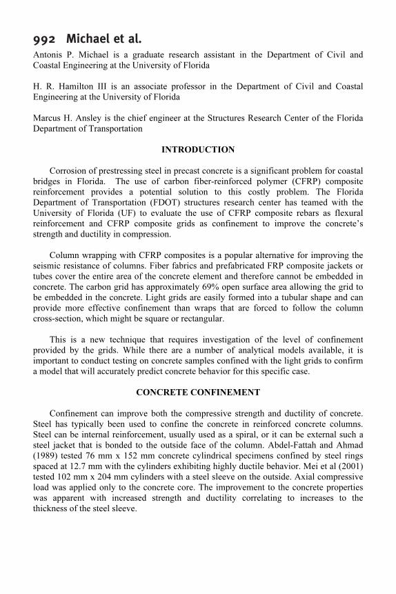
992 Michael et al.Antonis P. Michael is a graduate research assistant in the Department of Civil and
Coastal Engineering at the University of Florida
H. R. Hamilton III is an associate professor in the Department of Civil and Coastal
Engineering at the University of Florida
Marcus H. Ansley is the chief engineer at the Structures Research Center of the Florida
Department of Transportation
INTRODUCTION
Corrosion of prestressing steel in precast concrete is a significant problem for coastal
bridges in Florida. The use of carbon fiber-reinforced polymer (CFRP) composite
reinforcement provides a potential solution to this costly problem. The Florida
Department of Transportation (FDOT) structures research center has teamed with the
University of Florida (UF) to evaluate the use of CFRP composite rebars as flexural
reinforcement and CFRP composite grids as confinement to improve the concrete’s
strength and ductility in compression.
Column wrapping with CFRP composites is a popular alternative for improving the
seismic resistance of columns. Fiber fabrics and prefabricated FRP composite jackets or
tubes cover the entire area of the concrete element and therefore cannot be embedded in
concrete. The carbon grid has approximately 69% open surface area allowing the grid to
be embedded in the concrete. Light grids are easily formed into a tubular shape and can
provide more effective confinement than wraps that are forced to follow the column
cross-section, which might be square or rectangular.
This is a new technique that requires investigation of the level of confinement
provided by the grids. While there are a number of analytical models available, it is
important to conduct testing on concrete samples confined with the light grids to confirm
a model that will accurately predict concrete behavior for this specific case.
CONCRETE CONFINEMENT
Confinement can improve both the compressive strength and ductility of concrete.
Steel has typically been used to confine the concrete in reinforced concrete columns.
Steel can be internal reinforcement, usually used as a spiral, or it can be external such a
steel jacket that is bonded to the outside face of the column. Abdel-Fattah and Ahmad
(1989) tested 76 mm x 152 mm concrete cylindrical specimens confined by steel rings
spaced at 12.7 mm with the cylinders exhibiting highly ductile behavior. Mei et al (2001)
tested 102 mm x 204 mm cylinders with a steel sleeve on the outside. Axial compressive
load was applied only to the concrete core. The improvement to the concrete properties
was apparent with increased strength and ductility correlating to increases to the
thickness of the steel sleeve.

FRPRCS-7 993When fiber reinforced polymer (FRP) composites became widely available in the
civil sector they started replacing steel as external confinement reinforcement. One of the
primary applications of FRP composites is retrofit of concrete elements, primarily
columns, to improve their ductility. This is done mainly in seismic regions where
concrete structures experience large deformations. Column wrapping improves the
strength and ductility of the concrete, which improves the column’s performance under
earthquake loads.
Xiao and Wu (2000 and 2003), Lam and Teng (2004), Li et al. (2002), Harries and
Kharel (2002) and Li and Hadi (2003) tested concrete cylinders wrapped with FRP
composites. The strength of FRP confined concrete was increased, compared to the
unconfined concrete, between 1% and 420% depending on the type and amount of FRP
composite.
Shahawy et al. (2000) tested standard concrete cylinders wrapped with carbon fiber
fabrics in an epoxy matrix. The results varied depending on the number of carbon layers
applied. For an unconfined concrete strength of 41.4 MPa the confined strength of
cylinders was increased to 70 MPa for the 1-layer wrap and 110 MPa for the 4-layer
wrap. The ultimate strain for the 1-layer wrap was 0.007 and for the 4-layer wrap 0.016.
Pantelides et al. (1999) wrapped a bridge pier with carbon fiber composites and
tested it in situ. An unwrapped pier was also tested. The pier wrapped with carbon was
able to accommodate lateral movements two times larger than the unwrapped pier.
Mirmiran et al. (1998) manufactured round and square FRP tubes that were filled
with concrete and then tested in compression. The round tubes increased the peak axial
stress by as much as 2.5 times the peak axial stress of unconfined concrete and reached
axial strains 12 times higher than the axial strain at peak stress of unconfined concrete.
Confinement models to predict the maximum stress or the whole stress-strain curve
of confined concrete have been developed (Campione and Miraglia 2003; Li and Hadi
2003; Li et al. 2003; Xiao and Wu 2000, 2003; Fam and Rizkalla 2001). Most models
that describe the whole stress-strain curve of FRP confined concrete employ a bilinear
curve (second portion of the curve ascending) that in most cases works well. Most
models have been refined using data from concrete that is confined by FRP composite
materials that their amount and properties produce such behavior. Cases with lower grade
material or smaller amounts of FRP composites are scarce and have not been used to
demonstrate the applicability of the available models.
CFRP COMPOSITE GRIDS
Heavy CFRP composite grids with thicknesses of half an inch or more are produced
and used as primary reinforcement in concrete slabs or bridge decks in an effort to
address the problem of corrosion of steel reinforcement due to the use of deicing salts.
Rahman et al. (2000) used these carbon grids as reinforcement in a section of concrete
deck manufactured in a laboratory. The deck was supported on Steel I beams. They

994 Michael et al.reported that the behavior of the deck was satisfactory and the carbon grid could replace
steel reinforcement in bridge decks. Yost et al. (2001) tested the same type of heavy
CFRP grid as reinforcement in concrete beams. The use of the grid as flexural
reinforcement, however, resulted in brittle failure due to the rupture of the CFRP grid.
Light carbon grids (thickness 3 to 4 hundredths of an inch) are also available and are
used primarily for crack control in concrete structures. Harries and Gassman (2003)
conducted tests on reinforced concrete basin knockout panels that employed a light
carbon grid to control cracking. The grid reduced cracking of the panel significantly.
Shao et al. (2003) used the same light carbon grid to control plastic shrinkage cracking in
concrete. They concluded that the plastic shrinkage cracks were reduced by 50% to 65%.
EXPERIMENTAL PROGRAM
Column wrapping with CFRP composites is a popular alternative for improving the
seismic resistance of columns. Fiber fabrics and prefabricated FRP composite jackets or
tubes cover the entire area of the concrete element and therefore cannot be embedded in
concrete. The carbon grid has approximately 69% open surface area allowing the grid to
be embedded in the concrete. Light grids are easily formed into a tubular shape and can
provide more effective confinement than wraps that are forced to follow the column
cross-section, which might be square or rectangular. This is a new technique that requires
investigation of the level of confinement provided by the grids. While there are a number
of analytical models available, it is important to conduct testing on concrete samples
confined with the light grids to confirm a model that will accurately predict concrete
behavior for this specific case. Carbon grid properties are essential to any model to
determine concrete behavior and need to be determined through testing.
CFRP Grid Testing:
The CFRP composite grid tested in this program was fabricated from carbon fibers
embedded in an epoxy matrix. It was supplied in the form of rolls that are 1.041 m wide
and 274.32 m long. The strand spacing in the longitudinal direction was 45.7 mm and in
the transverse direction 40.6 mm (see Fig. 1). The CFRP grid had an openness of 69%
which means that only 31% of the surface area was covered by the carbon fibers.
Tensile properties of the grid were determined by testing two strands from each direction
using the specimen configuration shown in Fig. 2(a). Each end of the strand was
embedded into a short section of steel pipe for approximately 102 mm. The pipe was then
filled with an expansive grout leaving a free length of approximately 202 mm. Two foil
strain gauges were placed near the middle of the free-length of the specimen. Steel angles
welded to the opposing ends of the pipe anchors were used to attach the specimen to the
loading apparatus (Fig. 2(b)). Loading apparatus consisted of a hydraulic actuator
mounted to a stiff steel frame in which load was measured with a ring load cell. The
average load rate for the 4 specimens was approximately 145 Newtons per second with
data acquired approximately every half second.

FRPRCS-7 995Table 1 shows the results of the tensile tests. Strands taken from the longitudinal
direction are designated longitudinal (L) and strands taken from the transverse direction
are designated transverse (T). All the specimens ruptured at peak load. Three specimens
ruptured away from the anchor and only one close to the anchor. All specimens ruptured
at an interception of a longitudinal and a transverse strand. The average peak load per
strand was approximately 4.2 kN and is 16.7% lower than the load provided by the
manufacturer (4.9 kN). The average cross sectional area was approximately 6.26 mm2
.
The average strength was approximately 695.5 MPa and the average tensile modulus 64.5
GPa. The strength of each specimen was calculated by dividing the peak load by the
cross sectional area while the modulus was determined by a linear regression of the
stress-strain data (Fig. 3). The average of the 2 strain gages was used as the strain for
each stress level. The data shown in Fig. 3 do not extend to the rupture strength of the
specimen because the strain capacity of the strain gauges was exceeded.
Although insufficient tests were conducted to reveal statistical significance, some
indication of strength consistency can be determined from the test data. The coefficient
of variance (COV) for the strength was 24.2% while for the tensile modulus 17.4%. Both
COVs are high and can be attributed to the variability between the CFRP strands. Some
strands have a thick layer of epoxy resin covering them, which resulted in a lower fiber
volume fraction. According to the manufacturing company (TechFab) strands in both the
longitudinal and transverse direction have the same capacity. Our tests indicated a 9%
higher capacity for the transverse strands compared to the longitudinal strands but that
was attributed to the high variability and the small number of specimens in each
direction.
Cylinder Specimens:
Nine standard (152 mm x 304 mm) cylinders were cast. Two layers of grid, formed
into concentric tubular configurations and held with plastic ties, were cast into six of the
specimens while the remaining three cylinders were cast without reinforcement. The
cylinders with the CFRP grid were designated as grid cylinders. The grid cylinders were
divided into two groups (3 cylinders in each group) with each group having a different
grid diameter. The CFRP grid for the first group was formed into a tubular configuration
that was approximately 290-mm long with a diameter of 133.4 mm and a diameter of
139.7 mm for the second grid cylinder group (Fig. 4). Two layers of the grid were applied
with the grid lapping the 2 layers for an additional 180 mm for development purposes.
The grid openings were aligned to facilitate the flow of concrete through the grid. The
CFRP grid round tubes were placed inside plastic cylinder molds and concrete was added
(Fig. 5).
A Class II standard FDOT bridge deck concrete mixture was used to make the
cylinders. The specified minimum compressive strength of this concrete at 28 days is 31
MPa. Concrete was sampled as per ASTM C172. Both the control and grid cylinders
were cast in the field according to ASTM C31 except they were ambient cured rather
than moist cured.

996 Michael et al.All concrete cylinders were allowed to cure in the field inside the plastic mold for
approximately one month and were then taken to the laboratory where they remained
until 2 weeks before testing. At that time they were removed from their molds and sulfur
cement caps were placed on each end. The total curing time for all cylinder specimens
was 125 days.
Testing Details:
Nine cylinders (3 control and 6 grid) were tested in displacement control mode in
order to capture the post peak behavior of the specimens. Three control cylinders were
tested in load control mode using a cylinder tester since no significant post-peak behavior
was expected.
The smallest rate that the MTS loading frame could handle was approximately 1.5
mm per minute that resulted in a load rate of approximately 0.73 MPa per second. This
load rate is approximately two times higher than the maximum load rate allowed by
ASTM C39. Typical load head movement rate and load rate curves from the control
cylinders can be seen in Figs 6 and 7 respectively. The same load head movement rate
was used for all cylinder specimens tested in displacement control mode.
For the cylinder specimens to be tested in displacement control the 2200 kN loading
frame was used. Two Linear Variable Displacement Transducers (LVDTs) were used to
continuously record the length change of the specimens as load was applied. The two
LVDTs were placed on opposing sides of the cylinder to determine the average length
change of the cylinder specimen (Fig. 8). Load and movement data from the loading head
as well as data from the LVDTs were collected using a data acquisition program at a rate
of 50 Hz. This high rate was necessary to capture the post peak behavior of the cylinders.
Results and Discussion:
The average strength for the control cylinders tested in displacement control mode
was 47.8 MPa and the COV 2%. Results from the control cylinders can be found in Table
2. The control cylinders did not exhibit any significant post peak behavior but rather
crushed after reaching the peak load. Typical control cylinder types of fracture were: (a)
cone and split and (b) cone and shear. A control cylinder after testing can be seen in Fig.
9(a). The stress-strain curves for the control cylinders are depicted in Fig. 10. The first
control cylinder after reaching its peak load lost approximately half its strength almost
immediately but did not fall apart and continued to carry load contrary to the other two
control cylinders that lost all load carrying capacity abruptly soon after peak load.
The average strength of the grid cylinders was 52.9 MPa with a COV of 8.6%. Table
2 contains results from all grid cylinders. Grid cylinders typically failed when CFRP grid
strands ruptured. As expected, the concrete cover spalled off of the grid specimens before
the peak load was reached but the cylinders maintained most of their load carrying
capacity until grid strands started rupturing which took place in sequential rather than in
an abrupt manner. The carbon fibers in the CFRP grid are embedded in an epoxy matrix
that creates a smooth surface on the outside faces of the CFRP strands, which may have
contributed to spalling. A grid cylinder after testing with ruptured hoop CFRP grid

FRPRCS-7 997strands can be seen in Fig. 9(b). Experimental stress-axial strain curves for specimens
Grid 1 to 3 and specimens Grid 4 to 6 were plotted in Figures 11 and 12 respectively. The
stress values for the grid cylinders were calculated based on the area of the concrete core
enclosed by the CFRP grid and the axial strain was calculated as the average change in
the length, measured by the 2 LVDTs, of the cylinder over the original length.
The post peak behavior for all grid cylinders was different than that of control
cylinders. Grid cylinders reached higher peak loads and accommodated larger
displacements than the control cylinders. This is especially evident in Fig. 13 where
typical experimental stress-axial strain curves from both control and grid specimens were
plotted. The area under the post peak curve of the grid cylinders was approximately 3
times larger than the area of the control cylinders. Specimens Grid 4, 5 and 6 had
approximately 15% more area under the stress-strain curve than specimens Grid 1 and 3.
Specimen Grid 2 had approximately 45% more area under the curve than Grid 1 and 3
and 25% more area than specimens Grid 4, 5 and 6.
All grid cylinders reached a peak axial load followed by a descending post peak
curve. Other researchers observed such a behavior in lightly confined concrete. Harries
and Kharel (2003) made similar observations for their one and two-ply E-Glass confined
cylinders. Sfer et al. (2002) studied the behavior of concrete under triaxial compression
and their axial stress-strain curves at low confining pressures had a descending post peak
curve. The increase in the concrete strength was between 10% and 20%, which compares
to the 11% increase observed for our cylinders. In the case of the CFRP grid confined
concrete even with the two layers the concrete is still considered lightly confined since
the two CFRP grid layers add up to less than 1 layer of carbon fiber fabric when the
CFRP grid strand thickness is spread uniformly over the surface area of the concrete core.
In addition the strength and modulus of the CFRP grid was found to be lower than typical
carbon composites, which further reduces its confinement effectiveness. Therefore, the
post peak behavior observed for the CFRP grid cylinders verifies the observations made
by Harries and Kharel (2003) and Sfer et al. (2002).
CONFINEMENT MODEL
The present study is a part of a related project in which an all carbon reinforced
concrete pile is being evaluated for use in Florida’s highly corrosive coastal environment.
CFRP grid is one of the materials being evaluated as potential reinforcement. It is
anticipated that the piles will be designed to behave, when loaded in flexure, in an over-
reinforced manner to avoid the brittle failure mode that is usually precipitated by rupture
of the FRP reinforcement. One aspect of the pile design is that the confinement provided
by the grid will improve the flexural ductility of the compression zone, perhaps providing
a more favorable failure mode than the rupture of the FRP flexural reinforcement.
Most models for concrete confined with CFRP reinforcement are based on the fact
that, in most cases, a single layer of carbon fabric will provide adequate reinforcement to
sufficiently confine the concrete. When the CFRP grid is used as confinement
reinforcement it is expected that the confining pressure and confinement effectiveness

998 Michael et al.would be less than that of a fully jacketed system. Therefore models developed using
data from relatively highly confined concrete may not be adequate.
Several existing models were investigated to model the behavior of CFRP grid
confined concrete. All of the existing models examined are based on a constant thickness
of the FRP material that fully covers the external surface of the concrete. The hoop grid
strands only cover part of the area. One approach when using the existing models is to
determine an equivalent full coverage thickness for the hoop strands. The equivalent grid
thickness (teg
) was calculated based on the following expression:
h
tbnn
t
gggsl
eg
⋅⋅⋅
=
(1)
where: nl is the number of CFRP grid layers, n
gs is the number of grid strands, b
g is the
width of the grid strands, tg is the thickness of the grid strands and h is the height of the
cylinder. For columns or other concrete elements that have large axial lengths Eq. 1 can
be simplified as follows:
g
ggl
eg
s
tbn
t
⋅⋅
= (2)
where: sg is the CFRP grid strand spacing.
The secant modulus of elasticity of concrete (Ec) was calculated based on existing
empirical expressions (Nawy 2003):
'
4730cc
fE ⋅= (3)
where: f’c is the minimum specified compressive strength of concrete, in N/mm
2
, at 28
days.
To determine the confinement strength (fru
) simple pressure vessel mechanics were
used. The equilibrium condition requires the force from the confining strength be equal to
the force in the FRP encasement. The force from confinement is equal to the confining
strength times the diameter of the enclosed concrete and the force in the encasement is
equal to the strength of the encasement times twice the thickness of the FRP encasement.
By rearranging the equation the confinement strength (fru
) was found:
gu
g
eg
ruf
d
t
f ⋅
⋅
=
2
(4)
where fru
is the confinement strength, dg is the diameter of the CFRP grid tube and f
gu is
the ultimate strength of the CFRP grid strands.

FRPRCS-7 999Assuming that the confined concrete is in a triaxial stress state, the increase in
strength provided by the confinement is reflected in the maximum stress (f”cc
) for a
cylindrical specimen, which is defined as (Mander et al.1988):
ruccc
fkff ⋅+=1
'''
(5)
where k1 is the confinement effectiveness coefficient. The confinement effectiveness
coefficient for concrete confined by steel is usually taken between 2.8 and 4.1. Campione
and Miraglia (2003) found that the above values overestimate the confinement
effectiveness coefficient for concrete wrapped with FRP. They found the confinement
effectiveness coefficient for FRP wrapped concrete to be 2. For the purpose of this study
the confinement effectiveness coefficient was taken as 2.
The axial strain of CFRP grid confined concrete at the peak stress (εco
) was
determined in a similar manner as unconfined concrete using the following expression
(MacGregor 1997):
c
cc
co
E
f''
8.1 ⋅=ε (6)
Equations (5) and (6) were combined with the modified Hognestad stress-strain equation
as follows:
ε
ε
−
ε
ε⋅
⋅=
2
''2
co
c
co
c
ccc
ff
(7)
( )[ ]coccccc
Dff ε−ε⋅−⋅= 1
''
(8)
where εc is the concrete strain, ε
o is the strain at peak stress of unconfined concrete and ε
cu
is the ultimate strain. These equations are plotted in Fig. 14. The modified Hognestad
equations model the ascending branch (AB) with a parabolic relationship and the
descending branch BC with a linearly descending curve. The equation for region BC is
based on the deterioration constant (Dc) that controls the slope of the line.
The material properties of the CFRP grid strands were used to construct the stress-
strain curve of the CFRP grid confined concrete. The average strength of the control
cylinders tested in displacement control mode was taken as the strength of unconfined
concrete (f’c). An average CFRP grid tube diameter of 136.5 mm was used. The ultimate
concrete strain εcu
was assumed to be 0.00725 mm/mm. The average stress-strain curve
for the CFRP grid confined concrete was constructed using data from all grid cylinders.
The average stress-strain curve for the control cylinders was also constructed for
comparison. The deterioration constant was taken equal to 120 to match post peak
experimental data. All three curves are depicted in Fig. 15. The modified Hognestad
matches well with the experimental curve. The average experimental peak stress was 52.9
MPa while the model predicted a peak stress of 52 MPa. The predicted value is 1.7%

1000 Michael et al.lower than the experimental average. The average experimental strain at the peak stress
was 0.00259 mm/mm while the model predicted a strain of 0.00288 mm/mm at peak
stress. The predicted strain value is 11.2% higher than the average experimental value.
CONCLUSIONS
Concrete cylinders with embedded tubular CFRP grids were tested in compression to
failure to determine the post-peak behavior and ability of the grid to provide confinement
to the concrete. It was found that the CFRP grid does not produce a highly confined
concrete. This was expected since the amount of CFRP material provided by the grid is
low due to its large openings. Significant improvement, however, was observed in the
ductility of the concrete cylinders with embedded CFRP grid. Grid confinement also
resulted in an increase in the concrete strength of approximately 10.7%. The larger CFRP
grid diameter cylinders were more ductile compared to the smaller CFRP grid diameter
cylinders with the exception of cylinder Grid 2. However the difference in diameters and
the number of cylinders are small and therefore this conclusion is drawn with caution.
The equivalent grid thickness is a valid way of converting the concentrated thickness
of the CFRP grid to an equivalent thickness over the surface area of the concrete core.
Model results demonstrate that. The modified Hognestad provides an accurate prediction
of the behavior of concrete confined with the CFRP grid.
ACKNOWLEDGMENTS
This study is sponsored by the Florida Department of Transportation. The authors
gratefully acknowledge the contributions of Steve Eudy who set up and ran the data
acquisition system, as well as Frank Cobb, Tony Johnston, Paul Tighe, and David Allen
who helped prepare the testing apparatus.
NOTATION
teg
= equivalent grid thickness
nl
= number of grid layers
ngs
= number of grid strands
bg
= width of grid strands
tg
= thickness of grid strands
h
= height of cylinder
sg
= spacing of grid strands
Ec
= secant modulus of elasticity of concrete
f’c
= unconfined concrete strength
fru
= confinement strength
dg
= diameter of grid tube
fgu
= ultimate strength of grid strands
f’’
cc = confined concrete strength
k1
= confinement effectiveness coefficient
εco
= concrete axial strain at peak stress

FRPRCS-7 1001fc
= concrete stress
εc
= concrete axial strain
Dc
= deterioration constant
εcu
= ultimate concrete axial strain
REFERENCES
Referenced Standards
ASTM
C 31 Standard Practice for Making and Curing Concrete Test Specimens in the Field
C172 Standard Practice for Sampling Freshly Mixed Concrete
C 39 Standard Test Method for Compressive Strength of Cylindrical Concrete
Specimens
These publications may be obtained from this organization:
ASTM International
100 Barr Harbor Drive
West Conshohocken, PA 19428
Cited References
Abdel-Fattah, H. and Ahmad, S. H., (1989), “Behavior of Hoop-Confined High-Strength
Concrete under Axial and Shear Loads”, ACI Structural Journal, Vol. 86, No 6, pp. 652-
659.
Campione, G., Miraglia, N., (2003), “Strength and Strain Capacities of Concrete
Compression Members Reinforced with FRP”, Cement and Concrete Composites, Vol.
25, No 1, pp. 31-41.
Fam, A. Z. and Rizkalla, S. H., (2001), “Confinement Model for Axially Loaded
Concrete Confined by Circular Fiber-Reinforced Polymer Tubes”, ACI Structural
Journal, Vol. 98, No 4, pp. 451-461.
Harries, K. A. and Gassman, S. L., (2003), “Load Tests of Reinforced Concrete Catch
Basing Knockout Panels”, Department of Civil and Environmental Engineering,
University of South Carolina, Report No ST03-01, p. 21.
Harries, K. A., and Kharel, G., (2002), “Experimental Investigation of the Behavior of
Variably Confined Concrete”, Cement and Concrete Research, Vol. 33, No 6, pp. 873-
880.
Lam, L., and Teng, J. G., (2004), “Ultimate Condition of Fiber Reinforced Polymer-
Confined Concrete”, Journal of Composites for Construction, Vol. 8, No 6, pp. 539-548.
Li, J., Hadi, M.N.S., (2003), “Behaviour of Externally Confined High-Strength Concrete
Columns Under Eccentric Loading”, Composite Structures, Vol. 62, No 2, pp. 145-153.
Li, Y., Lin, C. and Sung, Y., (2002), “Compressive Behavior of Concrete Confined by
Various Types of FRP Composite Jackets”, Mechanics of Materials, Vol. 35, No 3-6, pp.
603-619.

1002 Michael et al.MacGregor, J. G., (1997), “Chapter 3: Materials”, Reinforced Concrete: Mechanics and
Design, Third Edition, Prentice Hall, New Jersey, pp. 35-81.
Mander, J. B., Priestley, M. J. N. and Park, R., (1988), “Theoretical Stress-Strain Model
for Confined Concrete”, Journal of Structural Engineering, Vol. 114, No 8, pp. 1804-
1826.
Mei, H., Kiousis, P. D., Ehsani, M. R. and Saadatmanesh, H., (2001), “Confinement
Effects on High-Strength Concrete”, ACI Structural Journal, Vol. 98, No 4, pp. 548-553.
Mirmiran, A., Shahawy, M., Samaan, M., El Echary, H., Mastrapa, J. C. and Pico, O.,
(1998), “Effect of Column Parameters on FRP-Confined Concrete”, Journal of
Composites for Construction, Vol. 2, No 4, pp. 175-185.
Nawy, E. G., (2003), “Chapter 3: Concrete”, Reinforced Concrete: A Fundamental
Approach, Fifth Edition, Prentice Hall, New Jersey, pp. 20-67.
Pantelides, C. P., Gergely, J., Reaveley, L. D. and Volnyy, V. A., (1999), “Retrofit of RC
Bridge Pier with CFRP Advanced Composites”, Journal of Structural Engineering, Vol.
125, No 10, pp. 1094-1099.
Park, R. and Paulay, T., (1975), “Chapter 6: Ultimate Deformation and Ductility of
Members with Flexure”, Reinforced Concrete Structures, John Wiley & Sons, New York,
pp. 195-269.
Rahman, A. H., Kingsley, C. Y. and Kobayashi, K., (2000), “Service and Ultimate Load
Behavior of Bridge Deck Reinforced with Carbon FRP Grid”, Journal of Composites for
Construction, Vol. 4, No 1, pp. 16-23.
Sfer, D., Carol, I., Gettu, R. and Etse, G., (2002), “Study of the Behavior of Concrete
under Triaxial Compression”, Journal of Engineering Mechanics, Vol. 128, No 2,
pp. 156-163.
Shahawy, M, Mirmiran, A. and Beitelman, T., (2000), “Tests and Modeling of Carbon-
Wrapped Concrete Columns”, Composites Part B: Engineering, Vol. 31, No 6-7,
pp. 471-480.
Shao, Y., Johnson, C. and Mirmiran, A., (2003), “Control of Plastic Shrinkage Cracking
of Concrete with TechFab Carbon FRP Grids”, Department of Civil, Construction, and
Environmental Engineering, North Carolina State University, Report to Tech-Fab Inc,
p. 7.
Xiao, Y. and Wu, H., (2000), “Compressive Behavior of Concrete Confined by Carbon
Fiber Composite Jackets”, Journal of Materials in Civil Engineering, Vol. 12, No 2,
pp. 139-146.
Xiao, Y. and Wu, H., (2003), “A Constitutive Model for Concrete Confinement with
Carbon Fiber Reinforced Plastics”, Journal of Reinforced Plastics and composites, Vol.
22, No 13, pp. 1187-1201.
Yost, J. R., Goodspeed, C. H. and Schmeckpeper, E. R., (2001), “Flexural Performance
of Concrete Beams Reinforced with FRP Grids”, Journal of Composites for
Construction, Vol. 5, No 1, pp. 18-25.
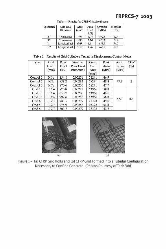
FRPRCS-7 1003
Figure 1 – (a) CFRP Grid Rolls and (b) CFRP Grid Formed into a Tubular ConfigurationNecessary to Confine Concrete. (Photos Courtesy of TechFab)

1004 Michael et al.
Figure 2 – (a) CFRP Grid Stand Specimen and (b) Test Set-Up for Tensile Testing of CFRPGrid Strands
Figure 3 – Stress-Strain Curves of CFRP Grid Tensile Tests

FRPRCS-7 1005
Figure 4 - CFRP Grid Round Tubes: (a) Cross Sectional View and (b) Longitudinal View
Figure 5 – CFRP Grid Cylinder Casting in the Field: (a) Beginning of Cylinder Casting and(b) Finishing Cylinder Casting
Figure 6 – Typical Load Head Movement Rate for Control Cylinders

1006 Michael et al.
Figure 7 – Typical Load Rate for Control Cylinders
Figure 8 – CFRP Grid Cylinder Test Set-Up

FRPRCS-7 1007
Figure 9 – Cylinders after Testing: (a) Control Cylinder, and (b) Grid Cylinder(Arrows Indicate Ruptured CFRP Grid Strands)
Figure 10 – Stress-Strain Curves for Control Cylinders
Figure 11 - Stress-Strain Curves for the 133.4 mm Core Diameter Grid Cylinders

1008 Michael et al.
Figure 12 - Stress-Strain Curves for the 139.7 mm Core Diameter Grid Cylinders
Figure 13 – Stress-Strain Curves for Typical Control and Grid Cylinders
Figure 14 – Modified Hognestad Stress Strain-Curve (Taken from Park and Pauly 1975)

FRPRCS-7 1009
Figure 15 – Average Experimental Stress-Strain Curves of Control and Grid Cylinders andthe Modified Hognestad Model for CFRP Grid Confined Concrete

1010 Michael et al.