Embed Size (px)
Citation preview
Concord ™
Concord RFDocument No. 466-1512 Rev. D
Installation Instructions
This document describes the installation, programming, test-ing, and troubleshooting procedures for installing Concord se-curity systems.
6
es
rd
5
26
About This Manual ........................... 5Special Installation Requirements ........................5
UL-Listed Installations ..................................5UL-Canada Listed Installations .....................6California State Fire Marshall Listed Installations6
Planning the Installation.................. 7Standard Panel ......................................................7Touchpads.............................................................7SuperBus RF Receivers ........................................7Power Line Carrier Card.......................................7Phone Supervision Card........................................7Supervised Wireless Siren ....................................8Phone Interface/Voice Module .............................8SnapCards .............................................................8SuperBus Hardwire InputModule ..................................................................8SuperBus Hardwire Output Module .....................8Interrogator 200 AudioVerification Module..............................................8
Installing the System....................... 8Determine the Panel Location...............................9Total System Power and Wire Length Guidelines9Mounting the Panel ...............................................10Identify Panel Components...................................11Installing Antennas ...............................................11Connecting the Panel to Earth Ground .................12Installing the Optional Power Line Carrier Card (60-755)12Installing the Optional Phone Supervision Card (60-789)12Installing Optional SnapCards ..............................13Connecting Detection Devices to Panel Zone Inputs13
Connecting IntrusionDetection Devices..........................................13Connecting 2-Wire SmokeDetectors........................................................14Connecting 4-Wire SmokeDetectors........................................................14
Connecting Speakers.............................................15
15-Watt Speaker (13-060) .............................15Hardwire Interior Speaker(60-528) .........................................................15
Connecting Piezo Sirens .......................................1Hardwire Exterior Siren(13-046) .........................................................16Slim Line Hardwire InteriorSiren (60-483-01)...........................................16
Installing SupervisedWireless Sirens (60-736-95) .................................17Output 1.................................................................17Connecting an Interrogator 200 (60-677) .............18Connecting Alphanumeric and LED Touchpads ..18Installing SuperBus Modules ................................18
SuperBus RF Receiver(60-764-95R) .................................................19Phone Interface/Voice Module (60-777) .......20Energy Saver Module (60-620) .....................21Hardwire Input Module (60-584) ..................21Hardwire Output Module(60-585) .........................................................22
Setting Device Address DIP Switches on Bus Devic22Installing an RJ-31X Phone Jack (13-081) ...........23Connecting the Phone Line to the Panel with a DB-8 Co24Connecting the AC PowerTransformer...........................................................25Powering Up the Panel..........................................2
Programming the Panel.................... 26Setting Alphanumeric Touchpad Device AddressesEntering Program Mode........................................26Touchpad Button Programming Functions ...........26Moving Through Program Mode Tiers and Menus27Programming Tier 1 Menu Items..........................27Programming Tier 2 Menu Items..........................29
Using Shortcut Numbers................................29Security Menu................................................29Phones Menu..................................................31Phone Options Menu .....................................35Timers Menu..................................................38Light Control Menu .......................................40
1
Touchpad Options Menu ...............................41Reporting Menu .............................................43Siren Options Menu .......................................47Sensors Menu.................................................48Audio Verification Menu...............................51Accessory Modules Menu .............................52Onboard Options Menu .................................55Wireless Touchpads Menu.............................60
Entering User Programming Mode .......................61User Codes Menu...........................................61Time and Date Menu .....................................62Set Up Schedules Menu.................................63Attach Schedules to Events Menu .................64Options Menu ................................................64System Version Menu....................................66Energy Saver Menu .......................................66
Testing the System.......................... 67Basic System Commands......................................67Testing Zones/Sensors ..........................................68
If a Zone/Sensor Does Not Test.....................69Testing Phone Communication.............................69Testing Central Station/Pager Communication.....69Testing Outputs .....................................................70Testing Light Control............................................70Testing the Energy Saver Module.........................70Downloader Programming....................................71
ToolBox DownloaderProgramming .................................................71
Troubleshooting ............................... 73Panel Power 74Access Codes 75Arming and Disarming 76Bypassing 76Wireless Sensor and Touchpad Batteries 77Central Station/Pager Reporting 77Alphanumeric Touchpads 78LED Touchpads 78Speakers 79Sirens 79Supervised Wireless Sirens 80Hardwire Zones 80Wireless Sensor Zones 81Wireless Touchpads 82Phones 82Light Control 83Energy Saver Module 84
Appendix A: System Planning Worksheets85
Programming Mode Menus and Settings89
2

3
d
d
-
o
Notices
FCC Notices
This equipment has been tested and found to comply with the limits for a class B digital device, pursuant to part 15 of the FCC rules. These limits are designed to provide
reasonable protection against harmful interference in a residential installation. This equipment generates, uses, and can radiate radio frequency energy and, if not installed an
used in accordance with the instructions, may cause harmful interference to radio communications. However, there is no guarantee that interference will not occur in a particular
installation. If this equipment does cause harmful interference to radio or television reception, which can be determined by turning the equipment off and on, the user is en-
couraged to try to correct the interference by one or more of the following measures:
• Install a quality radio or television outdoor antenna if the indoor antenna is not adequate.
• Reorient or relocate the panel.
• Move the panel away from the affected equipment.
• Move the panel away from any wire runs to the affected equipment.
• Connect the affected equipment and the panel to separate outlets, on different branch circuits.
• Consult the dealer or an experienced radio/TV technician for help.
• Send for the FCC booklet How to Identify and Resolve Radio-TV Interference Problems, available from the U.S. Government Printing Office, Washington, D.C.
20402. Stock Number: 004-000-00345-4.
Changes or modifications not expressly approved by Interactive Technologies, Inc. can void the user’s authority to operate the equipment.
This equipment complies with part 68 of the FCC rules. On the FCC label affixed to this equipment is the FCC Registration Number and Ringer Equivalence Number (REN)
for this equipment. If requested, provide this information to your telephone company.
The REN is used to calculate the maximum number of devices your telephone line will support with ringing service. In most areas the sum of all device RENs should not
exceed 5.0. Contact your local telephone company to determine the maximum REN for your calling area.
If your telephone equipment causes harm to the telephone network, your telephone company may temporarily disconnect your service. If possible, you will be notified in
advance. When advance notice is not practical, you will be notified as soon as possible. You will also be advised of your right to file a complaint with the FCC.
Your telephone company may make changes in its facilities, equipment, operations, or procedures that could affect the proper operation of your equipment. You will be given
advanced notice in order to maintain uninterrupted service.
If you experience trouble with this equipment, please contact
Interactive Technologies, Inc.2266 Second Street NorthNorth Saint Paul, MN 551091-800-777-1415
for service and repair information. The telephone company may ask you to disconnect this equipment from the network until the problem has been corrected or until you are
sure that the equipment is not malfunctioning.
This equipment may not be used on coin service provided by the telephone company. Connection to party lines is subject to state tariffs.
Declaration of Conformity (DoC)
Interactive Technologies, Inc. declares that the ITI model no. 60-792-95R is in conformity with Part 15 of the FCC Rules. Operation of this product is subject to the following
two conditions: (1) This device may not cause harmful interference, and (2) this device must accept any interference received, including interference that may cause undesire
operation.
Canada Notice
The Canadian Department of Communications label identifies certified equipment. This certification means that the equipment meets certain telecommunications network pro
tective, operational, and safety requirements. The department does not guarantee the equipment will operate to the user’s satisfaction.
Before installing this equipment, users should ensure that it is permissible to be connected to the facilities of the local telecommunications company. The equipment must als
be installed using an acceptable method of connection. In some cases, the company’s inside wiring associated with a single-line individual service may be extended by means
of a certified connector assembly (telephone extension cord). The customer should be aware that compliance with the above conditions may not prevent degradation of service
in some situations.
Repairs to certified equipment should be made by an authorized Canadian maintenance facility designated by the supplier. Any repairs or alterations made by the user to this
equipment, or equipment malfunctions, may give the telecommunications company cause to request the user to disconnect the equipment.
For your protection, make sure that the electrical ground connections of the power utility, telephone lines, and internal metallic water pipe system, if present, are connected together.
CautionDo not attempt to make connections yourself. Contact the appropriate electrician or electric inspections authority.
The Load Number (LN) assigned to each terminal device denotes the percentage of the total load to be connected to a telephone loop that is used by the device to prevent
overloading. The termination on a loop may consist of any combination of devices subject only to the requirement that the total of the LNs of all the devices does not exceed
100. Load Number: 0.2B AC

.
n
´´
e
-
“AVIS: - L ´étiquette du ministère des Communications du Canada identifie le matériel homologué. Cette étiquette certifie que le matériel est conforme a certaines normes de
protection, d ´ exploitation et de sécurité des réseaux de télécommunications. Le ministère n ´ assure toutefois pas que le matériel fonctionnera a la satisfaction de l ´ utilisateur
Avant d ´ installer ce matériel, l ´ utilisateur doit s ´ assurer qu´ il est permis de le raccorder aux installations de l ´ enterprise locale de télécommunication. Le matériel doit
également etre installé en suivant une méthod acceptée de raccordement. Dans certains cas, les fils intérieurs de l´ enterprise utilisés pour un service individuel a ligne unique
peuvent etre prolongés au moyen d´ un dispositif homologué de raccordement (cordon prolongateur téléphonique interne). L ´ abonné ne doit pas oublier qu ´ il est possible
que la conformité aux conditions énoncées ci-dessus n ´ empechent pas le dégradation du service dans certaines situations. Actuellement, les enterprises de télécommunicatio
ne permettent pas que l ´ on raccorde leur matériel a des jacks d ´ abonné, sauf dans les cas précis prévus pas les tarrifs particuliers de ces enterprises.
Les réparations de matériel homologué doivent etre effectuées pas un centre d ´ entretien canadien autorisé désigné par le fournisseur. La compagne de télécommunications
peut demander a l ´ utilisateur de débrancher un appareil a la suite de réparations ou de modifications effectuées par l ´ utilisateur ou a cause de mauvais fonctionnement.
Pour sa propre protection, l ´ utilisateur doit s ´ assurer que tous les fils de mise a la terre de la source d ´ énergie électrique, des lignes téléphoniques et des canalisations d
eau métalliques, s ´ il y en a, sont raccordés ensemble. Cette précaution est particulièrement importante dans les régions rurales.
Avertissment. - L ´ utilisateur ne doit pas tenter de faire ces raccordements lui-meme; il doit avoir recours a un service d ´ inspection des installations électriques, ou
a electricien, selon le cas”.
Une note explicative sur les indices de charge (voir 1.6) et leur emploi, a l ́ intention des utilisateurs du matériel terminal, doit etre incluse dans l ́ information qui accompagn
le materiel homologué. La note pourrait etre rédigée selon le modèle suivant:
“L ´ indice de charge (IC) assigné a chaque dispositif terminal indique, pour éviter toute surcharge, le pourcentage de la charge totale qui peut etre raccordée a un circuit télé
phonique bouclé utilisé par ce dispositif. La terminaison du circuit bouclé peut etre constituée de n ´ import somme des indices de charge de l ´ ensemble des dispositifs ne
dépasse pas 100.”
L ´ Indice de charge de cet produit est ____________.
Trademarks
ITI is a registered trademark of Interactive Technologies, Inc. Concord, SuperBus, SnapCard, and ToolBox are trademarks of Interactive Technologies, Inc. X-10 is a registered
trademark of X-10 (USA), Inc.
This manual may refer to products that are announced but are not yet available.
6 5 1 / 7 7 7 - 2 6 9 0
6 5 1 / 7 7 9 - 4 8 9 0
,
5-
ll
8-
About This Manual
This manual provides information for planning, in-stalling, programming, and testing this security sys-tem. When necessary, this manual refers you to other documentation included with compatible peripherals.
Planning sheets are included for you to record hard-ware layout and software programming settings.
Special Installation Require-ments
This security system can be used as a fire warning system, an intrusion alarm system, an emergency no-tification system, or any combination of the three.
Some installations may require configurations dictat-ed by city/state codes, insurance, or Underwriter’s Laboratories (UL). This section describes the various component and configuration listings.
UL-Listed Installations
This section describes the requirements for UL Listed installations.
Basic System
• Control Panel (60-734 or 60-792-95R)• SuperBus 8Z LED Touchpad (60-728) or
SuperBus 2x16 LCD Touchpad (60-746)• Standard Class II 24 VAC, 30 VA Power Trans-
former (60-761), Class II 24 VAC, 30 VA Line Carrier Power Transformer (60-762), or Standard Class II 24 VAC, 50 VA Power Transformer (60-778), Class II 24 VAC, 50 VA Line Carrier Power Transformer (60-779)
• Interior Speaker Siren (60-528), Exterior Speaker Siren (13-060), Slim Line Hardwire Interior Siren (60-483-01), or Hardwire Exterior Siren (13-046)
Basic system may also include a SuperBus RF Re-ceiver (60-764-95R-16, -32, or -MAX).
Household Burglary Alarm System Unit (UL 1023)
Basic system, plus:
• Hardwire Magnetic Contact (13-068 or 13-071)or Wireless Learn Mode Door/Window Sensor (60-362)
• IMMEDIATE TROUBLE BEEPS set to on• UL 98 OPTIONS set to on (see page 47)• RECEIVER FAILURE set to on• RF TX TIMEOUT set to 24 hours (if system
includes SuperBus RF Receiver and wireless smoke sensors)
Household Fire Warning System (UL 985)
Basic system used only with SuperBus 2x16 LCD Touchpads (60-746), plus:
• Hardwire Smoke Detector:System Sensor models 2100D, 2100TD, 2100S2100TS, 2400, or 2400T learned into Sensor Group 26 orSentrol (ESL) models 429AT, 521B, or 521BXTlearned into sensor group 26
• Wireless Smoke Sensor 60-506-319.5 or 60-6495 learned into sensor group 26
• IMMEDIATE TROUBLE BEEPS set to on• UL 98 OPTIONS set to on (see page 47)• RECEIVER FAILURE set to on• RF TX TIMEOUT set to 4 hours (if system
includes SuperBus RF Receiver and wireless smoke sensors)
UL 1023 & 985 24-Hour Backup
• For 24-hour backup, the total current draw for aconnected devices is limited to 90 mA continu-ous using a 4.0 AH battery, or 190 mA continu-ous using a 7.0 AH battery.
Commercial Burglary Alarm System Unit(Grade C UL 1610)
Basic system using Control Panel 60-801 or 60-8195R (currently not available), plus:
• Hardwire Magnetic Contact (13-068 or 13-071)or Wireless Learn Mode Door/Window Sensor (60-499)(continued on next page)
5
About This Manual
, p
5-
• ITI SAW PIR Sensor (60-639-95R), ITI Crystal PIR Sensor (60-703-95R), or DS924i PIR Sensor (60-511-01-95)
• IMMEDIATE TROUBLE BEEPS set to on• UL 98 OPTIONS set to on (see page 47)• RECEIVER FAILURE set to on• RF TX TIMEOUT set to 4 hours• 24-HOUR TAMPER set to on• SYSTEM TAMPER set to on• PHONE TEST set to on• PHONE TEST FREQ. set to 1• NEXT PHONE TEST set to 1
UL 1610 24-Hour Backup
• Same as UL 1023 & 985
Central Station Reporting
The panel has been tested with the following central station receivers using SIA and Contact ID reporting formats:
• ITI CS-5000 Central Station Receiver• Sur-Gard Central Station Receiver with models
SG-DRL2A and SG-CPM2
UL-Canada Listed Installations
This section describes the requirements for ULC (UL Canada) Listed installations.
Canadian Standards CSA Certified Accessories
Residential Burglary Alarm System Unit(ULC-S309)
Basic system as described for “UL-Listed Installa-tions” plus:
• Hardwire Magnetic Contact (13-068 or 13-071) or Wireless Learn Mode Door/Window Sensor (60-362)
Residential Fire Warning System Control Unit (ULC-S545-M89)
Basic system as described for “UL-Listed Installa-tions” plus:
• Hardwire Smoke Detector:System Sensor models 2100D, 2100TD, 2100S2100TS, 2400, 2400T learned into Sensor Grou26, orSentrol (ESL) models 429AT, 521B, or 521BXTlearned into sensor group 26
• Wireless Smoke Sensor 60-506-319.5 or 60-6495 learned into sensor group 26.
• IMMEDIATE TROUBLE BEEPS set to on• RF TX TIMEOUT set to 4 hours (if system
includes SuperBus RF Receiver and wireless smoke sensors).
NoteFor 24-hour backup, external power drain is limited to 90 mA continuous using a 4.0AH battery, or 190 mA continu-ous using a 7.0AH battery.
California State Fire Marshall Listed Installations
Same as Household Fire Warning System (UL 985), plus:
• SMOKE VERIFY must be set to off
6
Planning the Installation
t n.
s
r.
l. or
e by ns.
-
r-g lso to-
Planning the Installation
This section describes the systems’s capabilities to help you get familiar with the system. “Appendix A” provides planning sheets with tables that let you record the hardware and programming configuration of the system. Fill in all necessary information ahead of time to help prepare for system installation.
Standard Panel
The following describes the panel’s basic (out-of-box) hardware capabilities.
• Power: Input for an AC step-down, plug-in style transformer.
• Auxiliary Power Output: Output that supplies 8.5 to 13.5 VDC with up to 1 amp (with panel powered by 30 VA transformer) or 2 amps (with panel powered by 50 VA transformer) for bus devices and hardwired detectors, such as smoke and motion detectors.
• Bus A and B: Input and output that provides communication between bus devices and the panel.
• Siren Driver: Output that can drive an 8-ohm load and provides intrusion and fire alarm sounds for partition 1.
• 2 Onboard Outputs: Open-collector outputs that can be set up to activate other signalling devices, based on system events.
• Microphone Input: Input used for 2-way audio when used in conjunction with the Interrogator 200 Audio Verification Module.
• 8 Supervised Hardwire Zones: Inputs for vari-ous hardwired detectors. Zone 8 can be set up in programming to accept 2-wire smoke detectors.
• Built-In SuperBus Receiver (60-792-95R only): Allows use of up to 16 ITI 319.5 MHz. crystal and/or SAW Learn Mode wireless sen-sors and touchpads. Also allows supervision of Supervised Wireless Sirens.
• Phone Line Connection: Allows panel to com-municate with central monitoring station and/or pagers.
Touchpads
The following describes the different touchpads thacan be used for system programming and operatio
• SuperBus 8Z LED Touchpad: Provides control for basic system operation. LEDs indicate statufor 8 zones, arming (STAY, AWAY), alarm and trouble conditions, bypassed zones, and powe
• SuperBus 2x16 LCD Touchpad: Provides com-plete system programming and operation controDisplays system messages that prompt users finformation when needed and indicates systemstatus.
SuperBus RF Receivers
These receivers expand the system’s wireless zoncapacity by 16, 32, or the maximum zones allowed the panel. The receivers are compatible with all ITI319.5 MHz. crystal and SAW Learn Mode wirelesssensors, touchpads, and Supervised Wireless Sire
Power Line Carrier Card
Adding this card (which requires that the panel be powered using a Power Line Carrier Transformer) adds the following capabilities to the system:
• Allows the use of Supervised Wireless Sirens.• Allows the use of X-10 Powerhouse Lamp Mod
ules for light control and light activation during alarms.
Phone Supervision Card
Adding this card allows the panel to check for the corect phone line voltage (partition 1 only), upon dialinthe central station/pager number. The panel can abe programmed to check the phone line voltage aumatically, every hour on the hour.
7
Installing the System
up m
to er-.
n-r ets
s
s
Supervised Wireless Siren
Supervised Wireless Sirens plug into any standard electrical outlet and produce status and alarm sounds. The panel sends signals to the siren through the Power Line Carrier Card and Line Carrier Power Transform-er, through the AC electrical wiring.
The siren has a built-in transmitter that is used for su-pervising the siren. With the siren transmitter learned into panel memory (panels with receivers), the siren can notify the panel if it is unplugged, stops receiving panel signals, or has a low backup battery.
Phone Interface/Voice Module
This module allows system access and control using touch-tone telephones, on- or off-site. The module in-cludes an output for a speaker that sounds system sta-tus and alarm voice messages.
SnapCards
The following SnapCards expand the system as de-scribed:
• 8Z Input SnapCard: Provides eight additional hardwire zone inputs, of which two are dedicated for using 2-wire smoke detectors.
• 4 Output SnapCard: Provides four form C relay outputs that can be set up to activate other signalling devices, based on system events.
• 4Z Input/2 Output Combo SnapCard: Pro-vides four hardwire zone inputs and two outputs that can be set up to activate other signalling devices, based on system events.
SuperBus Hardwire InputModule
Provides eight additional hardwire zone inputs.
SuperBus Hardwire Output Module
Provides four form C relay outputs that can be set to activate other signalling devices, based on systeevents.
Interrogator 200 AudioVerification Module
Adding this module allows central station operators listen-in and talk to occupants on the premises, to vify the emergency when an alarm report is received
Installing the System
This section describes how to install the system cotrol panel. Before starting the installation, plan yousystem layout and programming using the worksheprovided in Appendix A.
Installing the system consists of the following:
• Determining the Panel Location• Total System Power and Wire Length Guideline• Mounting the Panel• Identifying Panel Main Components• Installing the Optional Power Line Carrier Card• Installing Optional SnapCards• Connecting Detection Devices to Panel Zone
Inputs• Connecting Speakers• Connecting Piezo Sirens• Connecting a Garage Door Opener• Connecting an Interrogator 200• Connecting Alphanumeric and LED Touchpads• Installing SuperBus Modules• Setting Unit Number DIP Switches on SuperBu
Devices• Installing an RJ-31X Phone Jack• Connecting the Phone Line to the Panel with a
DB-8 Cord• Connecting the AC Power Transformer• Powering Up the Panel
8
Installing the System
n o 0
n
ire
d ng
Determine the Panel Location
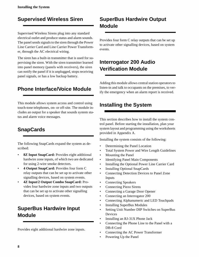
Before permanently mounting the panel, determine panel location using the following guidelines:
• Centrally locate the panel with relation to detec-tion devices whenever possible, to help reduce wire run lengths and labor.
• Avoid running wires parallel with electrical wir-ing or fixtures such as fluorescent lighting, to prevent wire runs from picking up electrical noise.
• Mount the panel at a comfortable working height (about 45 to 55 inches from the floor to the bot-tom of the panel, as shown in Figure 1).
• Leave space to the left and right of the panel for wiring, phone jack, and mounting optional mod-ules.
• For wireless panels or hardwire panels that include a SuperBus RF Receiver, allow at least 9 inches above the panel cabinet for antennas.
• Allow at least 24 inches in front of the panel to open the panel door.
Figure 1. Determining Panel Location
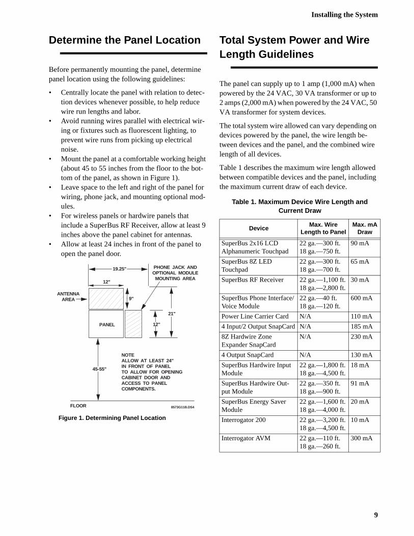
Total System Power and Wire Length Guidelines
The panel can supply up to 1 amp (1,000 mA) whepowered by the 24 VAC, 30 VA transformer or up t2 amps (2,000 mA) when powered by the 24 VAC, 5VA transformer for system devices.
The total system wire allowed can vary depending odevices powered by the panel, the wire length be-tween devices and the panel, and the combined wlength of all devices.
Table 1 describes the maximum wire length allowebetween compatible devices and the panel, includithe maximum current draw of each device.
PANEL
19.25"
12"
12"
21"
45-55"
PHONE JACK ANDOPTIONAL MODULE
MOUNTING AREA
ANTENNAAREA
NOTEALLOW AT LEAST 24"IN FRONT OF PANELTO ALLOW FOR OPENINGCABINET DOOR ANDACCESS TO PANELCOMPONENTS.
FLOOR 8573G11B.DS4
9"
Table 1. Maximum Device Wire Length and Current Draw
DeviceMax. Wire
Length to PanelMax. mA
Draw
SuperBus 2x16 LCD Alphanumeric Touchpad
22 ga.—300 ft.18 ga.—750 ft.
90 mA
SuperBus 8Z LEDTouchpad
22 ga.—300 ft.18 ga.—700 ft.
65 mA
SuperBus RF Receiver 22 ga.—1,100 ft.18 ga.—2,800 ft.
30 mA
SuperBus Phone Interface/Voice Module
22 ga.—40 ft.18 ga.—120 ft.
600 mA
Power Line Carrier Card N/A 110 mA
4 Input/2 Output SnapCard N/A 185 mA
8Z Hardwire Zone Expander SnapCard
N/A 230 mA
4 Output SnapCard N/A 130 mA
SuperBus Hardwire Input Module
22 ga.—1,800 ft.18 ga.—4,500 ft.
18 mA
SuperBus Hardwire Out-put Module
22 ga.—350 ft.18 ga.—900 ft.
91 mA
SuperBus Energy Saver Module
22 ga.—1,600 ft.18 ga.—4,000 ft.
20 mA
Interrogator 200 22 ga.—3,200 ft.18 ga.—4,500 ft.
10 mA
Interrogator AVM 22 ga.—110 ft.18 ga.—260 ft.
300 mA
9
Installing the System
4.
e
y
g
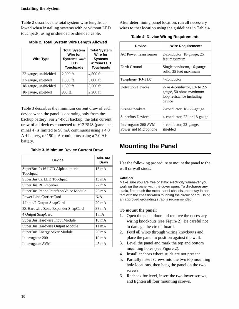
Table 2 describes the total system wire lengths al-lowed when installing systems with or without LED touchpads, using unshielded or shielded cable.
Table 3 describes the minimum current draw of each device when the panel is operating only from the backup battery. For 24-hour backup, the total current draw of all devices connected to +12 BUS (panel ter-minal 4) is limited to 90 mA continuous using a 4.0 AH battery, or 190 mA continuous using a 7.0 AH battery.
After determining panel location, run all necessarywires to that location using the guidelines in Table
Mounting the Panel
Use the following procedure to mount the panel to thwall or wall studs.
CautionMake sure you are free of static electricity whenever you work on the panel with the cover open. To discharge any static, first touch the metal panel chassis, then stay in con-tact with the chassis when touching the circuit board. Using an approved grounding strap is recommended.
To mount the panel:1. Open the panel door and remove the necessar
wiring knockouts (see Figure 2). Be careful notto damage the circuit board.
2. Feed all wires through wiring knockouts and place the panel in position against the wall.
3. Level the panel and mark the top and bottom mounting holes (see Figure 2).
4. Install anchors where studs are not present.5. Partially insert screws into the two top mountin
hole locations, then hang the panel on the two screws.
6. Recheck for level, insert the two lower screws,and tighten all four mounting screws.
Table 2. Total System Wire Length Allowed
Wire Type
Total System Wire for
Systems with LED
Touchpads
Total System Wire for Systems
without LED Touchpads
22-gauge, unshielded
22-gauge, shielded
2,000 ft.
1,300 ft.
4,500 ft.
3,000 ft.
18-gauge, unshielded
18-gauge, shielded
1,600 ft.
900 ft.
3,500 ft.
2,200 ft.
Table 3. Minimum Device Current Draw
DeviceMin. mA
Draw
SuperBus 2x16 LCD AlphanumericTouchpad
15 mA
SuperBus 8Z LED Touchpad 15 mA
SuperBus RF Receiver 27 mA
SuperBus Phone Interface/Voice Module 25 mA
Power Line Carrier Card N/A
4 Input/2 Output SnapCard 20 mA
8Z Hardwire Zone Expander SnapCard 38 mA
4 Output SnapCard 1 mA
SuperBus Hardwire Input Module 18 mA
SuperBus Hardwire Output Module 11 mA
SuperBus Energy Saver Module 20 mA
Interrogator 200 10 mA
Interrogator AVM 45 mA
Table 4. Device Wiring Requirements
Device Wire Requirements
AC Power Transformer 2-conductor, 18-gauge, 25 feet maximum
Earth Ground Single conductor, 16-gauge solid, 25 feet maximum
Telephone (RJ-31X) 4-conductor
Detection Devices 2- or 4-conductor, 18- to 22-gauge, 50 ohms maximum loop resistance including device
Sirens/Speakers 2-conductor, 18- 22-gauge
SuperBus Devices 4-conductor, 22- or 18-gauge
Interrogator 200 AVM Power and Microphone
4-conductor, 22-gauge, shielded
10
Installing the System
n-
).
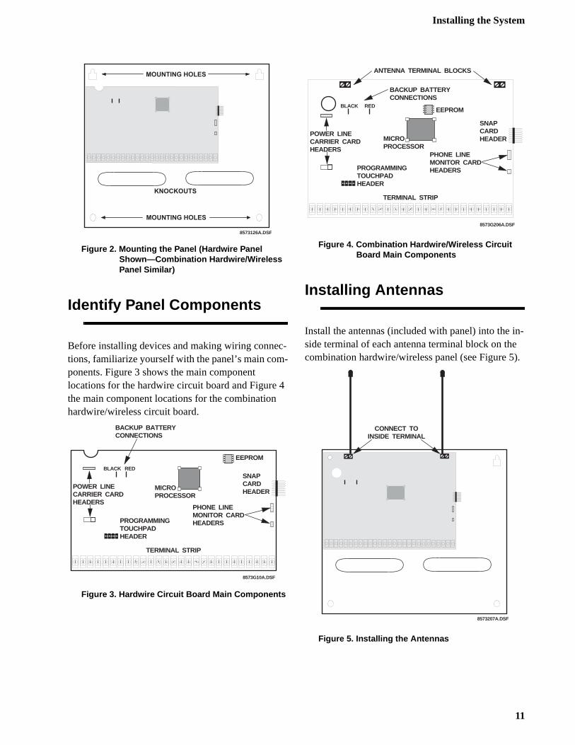
Figure 2. Mounting the Panel (Hardwire Panel Shown—Combination Hardwire/Wireless Panel Similar)
Identify Panel Components
Before installing devices and making wiring connec-tions, familiarize yourself with the panel’s main com-ponents. Figure 3 shows the main component locations for the hardwire circuit board and Figure 4 the main component locations for the combination hardwire/wireless circuit board.
Figure 3. Hardwire Circuit Board Main Components
Figure 4. Combination Hardwire/Wireless Circuit Board Main Components
Installing Antennas
Install the antennas (included with panel) into the iside terminal of each antenna terminal block on thecombination hardwire/wireless panel (see Figure 5
Figure 5. Installing the Antennas
8573126A.DSF
M O U N T I N G H O L E S
M O U N T I N G H O L E S
K N O C K O U T S
8573G10A.DSF
SNAPCARDHEADER
POWER LINECARRIER CARDHEADERS
BACKUP BATTERYCONNECTIONS
TERMINAL STRIP
MICROPROCESSOR
BLACK
EEPROM
PHONE LINEMONITOR CARDHEADERSPROGRAMMING
TOUCHPADHEADER
RED
8573G206A.DSF
SNAPCARDHEADER
POWER LINECARRIER CARDHEADERS
BACKUP BATTERYCONNECTIONS
TERMINAL STRIP
MICROPROCESSOR
BLACKEEPROM
PHONE LINEMONITOR CARDHEADERSPROGRAMMING
TOUCHPADHEADER
RED
ANTENNA TERMINAL BLOCKS
8573207A.DSF
CONNECT TOINSIDE TERMINAL
11
Installing the System
n l olt-
re
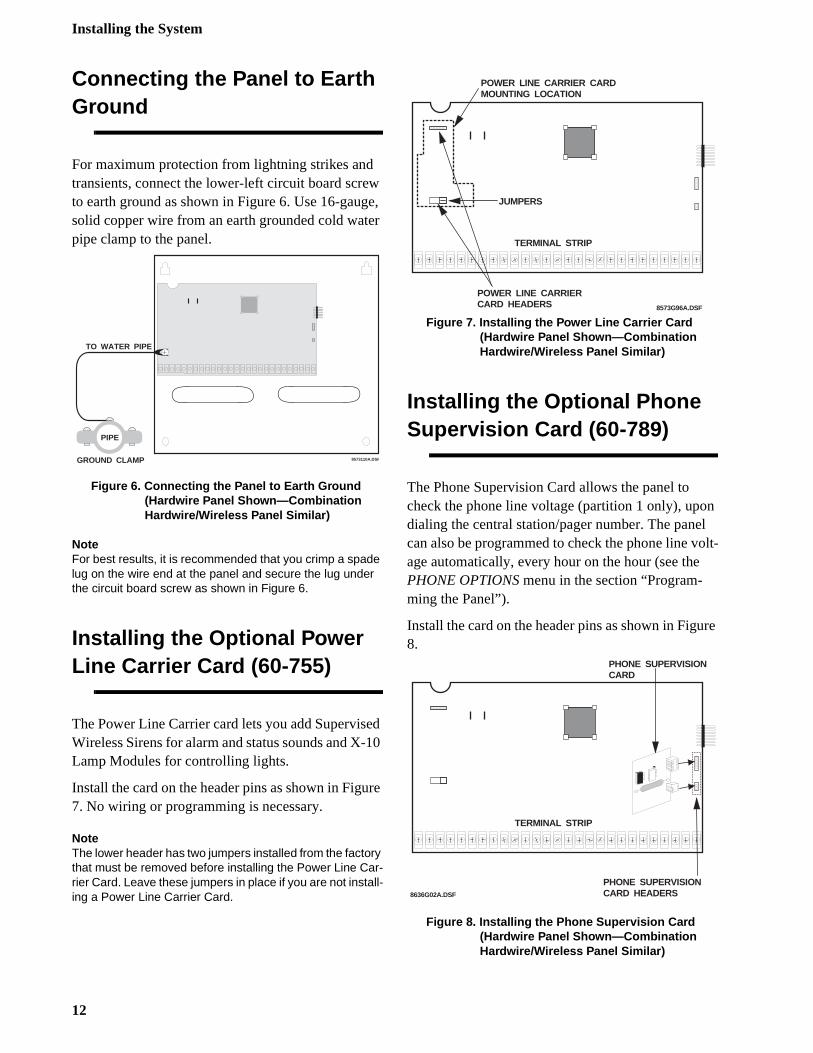
Connecting the Panel to Earth Ground
For maximum protection from lightning strikes and transients, connect the lower-left circuit board screw to earth ground as shown in Figure 6. Use 16-gauge, solid copper wire from an earth grounded cold water pipe clamp to the panel.
Figure 6. Connecting the Panel to Earth Ground (Hardwire Panel Shown—Combination Hardwire/Wireless Panel Similar)
NoteFor best results, it is recommended that you crimp a spade lug on the wire end at the panel and secure the lug under the circuit board screw as shown in Figure 6.
Installing the Optional Power Line Carrier Card (60-755)
The Power Line Carrier card lets you add Supervised Wireless Sirens for alarm and status sounds and X-10 Lamp Modules for controlling lights.
Install the card on the header pins as shown in Figure 7. No wiring or programming is necessary.
NoteThe lower header has two jumpers installed from the factory that must be removed before installing the Power Line Car-rier Card. Leave these jumpers in place if you are not install-ing a Power Line Carrier Card.
Figure 7. Installing the Power Line Carrier Card (Hardwire Panel Shown—Combination Hardwire/Wireless Panel Similar)
Installing the Optional Phone Supervision Card (60-789)
The Phone Supervision Card allows the panel to check the phone line voltage (partition 1 only), upodialing the central station/pager number. The panecan also be programmed to check the phone line vage automatically, every hour on the hour (see thePHONE OPTIONS menu in the section “Program-ming the Panel”).
Install the card on the header pins as shown in Figu8.
Figure 8. Installing the Phone Supervision Card (Hardwire Panel Shown—Combination Hardwire/Wireless Panel Similar)
8573110A.DSF
TO WATER PIPE
PIPE
GROUND CLAMP
POWER LINE CARRIER CARD HEADERS
TERMINAL STRIP
8573G96A.DSF
POWER LINE CARRIER CARDMOUNTING LOCATION
JUMPERS
8636G02A.DSF
PHONE SUPERVISIONCARD HEADERS
TERMINAL STRIP
PHONE SUPERVISIONCARD
12
Installing the System
C
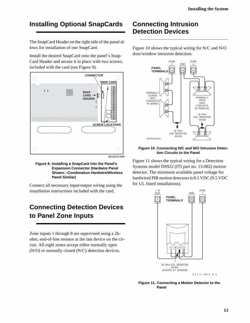
Installing Optional SnapCards
The SnapCard Header on the right side of the panel al-lows for installation of one SnapCard.
Install the desired SnapCard onto the panel’s Snap-Card Header and secure it in place with two screws, included with the card (see Figure 9).
Figure 9. Installing a SnapCard into the Panel’s Expansion Connector (Hardwire Panel Shown—Combination Hardwire/Wireless Panel Similar)
Connect all necessary input/output wiring using the installation instructions included with the card.
Connecting Detection Devices to Panel Zone Inputs
Zone inputs 1 through 8 are supervised using a 2k-ohm, end-of-line resistor at the last device on the cir-cuit. All eight zones accept either normally open(N/O) or normally closed (N/C) detection devices.
Connecting IntrusionDetection Devices
Figure 10 shows the typical wiring for N/C and N/Odoor/window intrusion detection.
Figure 10. Connecting N/C and N/O Intrusion Detec-tion Circuits to the Panel
Figure 11 shows the typical wiring for a Detection Systems model DS922 (ITI part no. 13-082) motiondetector. The minimum available panel voltage forhardwired PIR motion detectors is 8.5 VDC (9.5 VDfor UL listed installations).
Figure 11. Connecting a Motion Detector to the Panel
8573127A.DSF
S N A P C A R D
S C R E W L O C A T I O N S
C O N N E C T O R
S N A PC A R DH E A D E R
13 14 15
ZONE2 GND
ZONE3
NORMALLYOPEN (N/O)
CONTACTSIN PARALLEL
2k OhmEOL RESISTOR
49-454
2k OhmEOL RESISTOR
49-454
NORMALLYCLOSED
(N/C)CONTACTSIN SERIES
P A N E LT E R M I N A L S
8573G23A.DS4
P A N E LT E R M I N A L S
8 5 7 3 1 4 0 A . D S F
LP- + LN
2k Ohm EOL RESISTOR49-454
(LOCATE AT SENSOR)
4 20 21
GND+ 12BUS
ZONE7
13
Installing the System
rs is ro-
d
te
nd
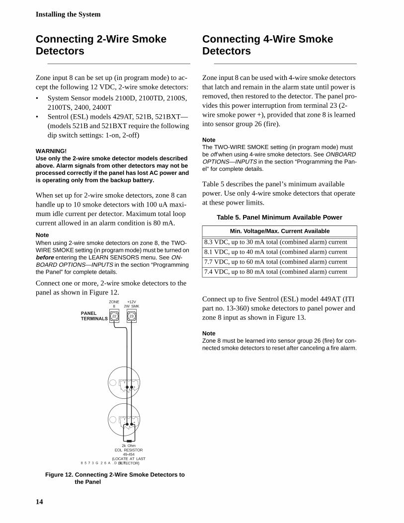
Connecting 2-Wire SmokeDetectors
Zone input 8 can be set up (in program mode) to ac-cept the following 12 VDC, 2-wire smoke detectors:
• System Sensor models 2100D, 2100TD, 2100S, 2100TS, 2400, 2400T
• Sentrol (ESL) models 429AT, 521B, 521BXT—(models 521B and 521BXT require the following dip switch settings: 1-on, 2-off)
WARNING!Use only the 2-wire smoke detector models described above. Alarm signals from other detectors may not be processed correctly if the panel has lost AC power and is operating only from the backup battery.
When set up for 2-wire smoke detectors, zone 8 can handle up to 10 smoke detectors with 100 uA maxi-mum idle current per detector. Maximum total loop current allowed in an alarm condition is 80 mA.
NoteWhen using 2-wire smoke detectors on zone 8, the TWO-WIRE SMOKE setting (in program mode) must be turned on before entering the LEARN SENSORS menu. See ON-BOARD OPTIONS—INPUTS in the section “Programming the Panel” for complete details.
Connect one or more, 2-wire smoke detectors to the panel as shown in Figure 12.
Figure 12. Connecting 2-Wire Smoke Detectors to the Panel
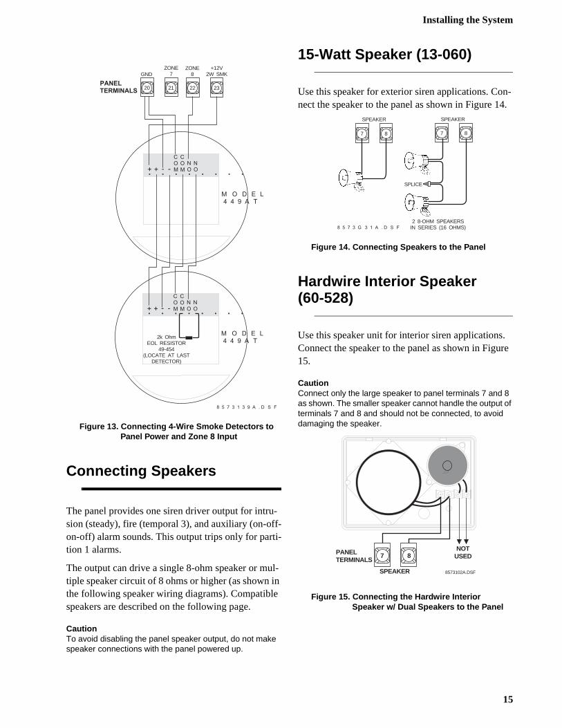
Connecting 4-Wire SmokeDetectors
Zone input 8 can be used with 4-wire smoke detectothat latch and remain in the alarm state until powerremoved, then restored to the detector. The panel pvides this power interruption from terminal 23 (2-wire smoke power +), provided that zone 8 is learneinto sensor group 26 (fire).
NoteThe TWO-WIRE SMOKE setting (in program mode) must be off when using 4-wire smoke detectors. See ONBOARD OPTIONS—INPUTS in the section “Programming the Pan-el” for complete details.
Table 5 describes the panel’s minimum available power. Use only 4-wire smoke detectors that operaat these power limits.
Connect up to five Sentrol (ESL) model 449AT (ITIpart no. 13-360) smoke detectors to panel power azone 8 input as shown in Figure 13.
NoteZone 8 must be learned into sensor group 26 (fire) for con-nected smoke detectors to reset after canceling a fire alarm.
22 23
ZONE8
+12V2W SMK
+-
+-
2k OhmEOL RESISTOR
49-454(LOCATE AT LAST
DETECTOR)
P A N E LT E R M I N A L S
8 5 7 3 G 2 6 A . D S F
Table 5. Panel Minimum Available Power
Min. Voltage/Max. Current Available
8.3 VDC, up to 30 mA total (combined alarm) current
8.1 VDC, up to 40 mA total (combined alarm) current
7.7 VDC, up to 60 mA total (combined alarm) current
7.4 VDC, up to 80 mA total (combined alarm) current
14
Installing the System
n-4.
. re
Figure 13. Connecting 4-Wire Smoke Detectors to Panel Power and Zone 8 Input
Connecting Speakers
The panel provides one siren driver output for intru-sion (steady), fire (temporal 3), and auxiliary (on-off-on-off) alarm sounds. This output trips only for parti-tion 1 alarms.
The output can drive a single 8-ohm speaker or mul-tiple speaker circuit of 8 ohms or higher (as shown in the following speaker wiring diagrams). Compatible speakers are described on the following page.
CautionTo avoid disabling the panel speaker output, do not make speaker connections with the panel powered up.
15-Watt Speaker (13-060)
Use this speaker for exterior siren applications. Conect the speaker to the panel as shown in Figure 1
Figure 14. Connecting Speakers to the Panel
Hardwire Interior Speaker(60-528)
Use this speaker unit for interior siren applicationsConnect the speaker to the panel as shown in Figu15.
CautionConnect only the large speaker to panel terminals 7 and 8 as shown. The smaller speaker cannot handle the output of terminals 7 and 8 and should not be connected, to avoid damaging the speaker.
Figure 15. Connecting the Hardwire Interior Speaker w/ Dual Speakers to the Panel
22 23
ZONE8
+12V2W SMK
P A N E LT E R M I N A L S
8 5 7 3 1 3 9 A . D S F
20 21
GNDZONE
7
+
COM. . . . . . . .+ - -
COM
NO
NO
M O D E L4 4 9 A T
+
COM. . . . . . . .+ - -
COM
NO
NO
M O D E L4 4 9 A T
2k OhmEOL RESISTOR
49-454(LOCATE AT LAST
DETECTOR)
2 8-OHM SPEAKERSIN SERIES (16 OHMS)
SPLICE
7 8
SPEAKER
7 8
8 5 7 3 G 3 1 A . D S F
SPEAKER
8573102A.DSF
PANELTERMINALS
87
SPEAKER
NOTUSED
15
Installing the System
17.
18.
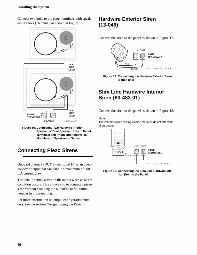
Connect two units to the panel terminals with speak-ers in series (16 ohms), as shown in Figure 16.
Figure 16. Connecting Two Hardwire Interior Speaker w/ Dual Speaker Units to Panel Terminals and Phone Interface/Voice Module with Speakers in Series
Connecting Piezo Sirens
Onboard output 2 (OUT 2—terminal 10) is an open-collector output that can handle a maximum of 200 mA current draw.
The default setting activates the output when an alarm condition occurs. This allows you to connect a piezo siren without changing the output’s configuration number in programming.
For more information on output configuration num-bers, see the section “Programming the Panel.”
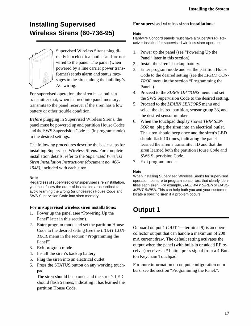
Hardwire Exterior Siren(13-046)
Connect the siren to the panel as shown in Figure
Figure 17. Connecting the Hardwire Exterior Siren to the Panel
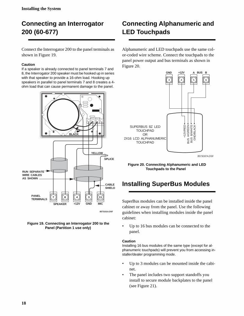
Slim Line Hardwire InteriorSiren (60-483-01)
Connect the siren to the panel as shown in Figure
NoteThe volume switch settings inside the siren do not affect the siren output.
Figure 18. Connecting the Slim Line Hardwire Inte-rior Siren to the Panel
8573103A.DSF
PANELTERMINALS
87
SPEAKER
NOTUSED
NOTUSED
4 10
RED
BLACK
P A N E LT E R M I N A L S
8 5 7 3 G 2 8 A . D S F
+12V OUT2
P A N E LT E R M I N A L S
8 5 7 3 G 2 7 A . D S F
4 10
+12V OUT21
HIGH2
GND3
LOW
N O TU S E D
16
Installing the System
e
ng.
nd
D
d
--
Installing SupervisedWireless Sirens (60-736-95)
Supervised Wireless Sirens plug di-rectly into electrical outlets and are not wired to the panel. The panel (when powered by a line carrier power trans-former) sends alarm and status mes-sages to the siren, along the building’s AC wiring.
For supervised operation, the siren has a built-in transmitter that, when learned into panel memory, transmits to the panel receiver if the siren has a low battery or other trouble condition.
Before plugging in Supervised Wireless Sirens, the panel must be powered up and partition House Codes and the SWS Supervision Code set (in program mode) to the desired settings.
The following procedures describe the basic steps for installing Supervised Wireless Sirens. For complete installation details, refer to the Supervised Wireless Siren Installation Instructions (document no. 466-1548), included with each siren.
NoteRegardless of supervised or unsupervised siren installation, you must follow the order of installation as described to avoid learning the wrong (or undesired) House Code and SWS Supervision Code into siren memory.
For unsupervised wireless siren installations:1. Power up the panel (see “Powering Up the
Panel” later in this section).2. Enter program mode and set the partition House
Code to the desired setting (see the LIGHT CON-TROL menu in the section “Programming the Panel”).
3. Exit program mode.4. Install the siren’s backup battery.5. Plug the siren into an electrical outlet.6. Press the STATUS button on any working touch-
pad.The siren should beep once and the siren’s LED should flash 5 times, indicating it has learned the partition House Code.
For supervised wireless siren installations:
NoteHardwire Concord panels must have a SuperBus RF Re-ceiver installed for supervised wireless siren operation.
1. Power up the panel (see “Powering Up the Panel” later in this section).
2. Install the siren’s backup battery.3. Enter program mode and set the partition Hous
Code to the desired setting (see the LIGHT CON-TROL menu in the section “Programming the Panel”).
4. Proceed to the SIREN OPTIONS menu and set the SWS Supervision Code to the desired setti
5. Proceed to the LEARN SENSORS menu and select the desired partition, sensor group 33, athe desired sensor number.
6. When the touchpad display shows TRIP SEN-SOR nn, plug the siren into an electrical outlet. The siren should beep once and the siren’s LEshould flash 10 times, indicating the panel learned the siren’s transmitter ID and that the siren learned both the partition House Code anSWS Supervision Code.
7. Exit program mode.
NoteWhen installing Supervised Wireless Sirens for supervised operation, be sure to program sensor text that clearly iden-tifies each siren. For example, HALLWAY SIREN or BASE-MENT SIREN. This can help both you and your customer locate a specific siren if a problem occurs.
Output 1
Onboard output 1 (OUT 1—terminal 9) is an open-collector output that can handle a maximum of 200mA current draw. The default setting activates the output when the panel (with built-in or added RF receiver) receives a * button press signal from a 4-Button Keychain Touchpad.
For more information on output configuration num-bers, see the section “Programming the Panel.”.
17
Installing the System
ol-he
el
l
bi-
l
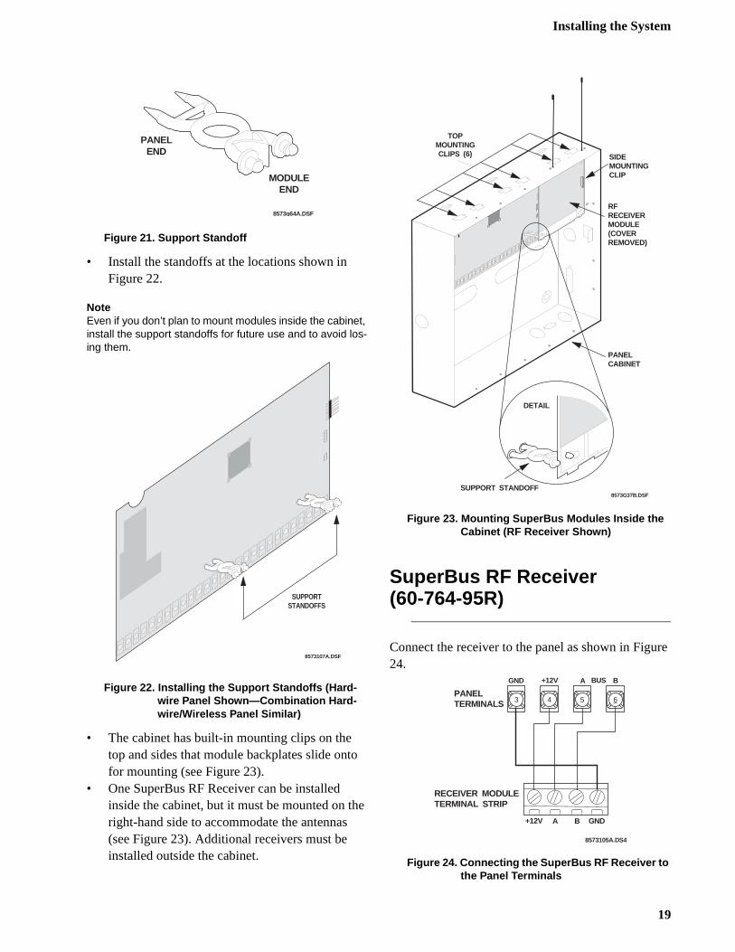
Connecting an Interrogator 200 (60-677)
Connect the Interrogator 200 to the panel terminals as shown in Figure 19.
CautionIf a speaker is already connected to panel terminals 7 and 8, the Interrogator 200 speaker must be hooked up in series with that speaker to provide a 16-ohm load. Hooking up speakers in parallel to panel terminals 7 and 8 creates a 4-ohm load that can cause permanent damage to the panel.
Figure 19. Connecting an Interrogator 200 to the Panel (Partition 1 use only)
Connecting Alphanumeric and LED Touchpads
Alphanumeric and LED touchpads use the same cor-coded wire scheme. Connect the touchpads to tpanel power output and bus terminals as shown inFigure 20.
Figure 20. Connecting Alphanumeric and LED Touchpads to the Panel
Installing SuperBus Modules
SuperBus modules can be installed inside the pancabinet or away from the panel. Use the following guidelines when installing modules inside the panecabinet:
• Up to 16 bus modules can be connected to thepanel.
CautionInstalling 16 bus modules of the same type (except for al-phanumeric touchpads) will prevent you from accessing in-staller/dealer programming mode.
• Up to 3 modules can be mounted inside the canet.
• The panel includes two support standoffs you install to secure module backplates to the pane(see Figure 21).
87
SPEAKER
8573101A.DSF
4
+12V
3
GND
11
MIC
SPLICE
RUN SEPARATEWIRE CABLESAS SHOWN
BLACK
YELLOW
PANELTERMINALS
CABLESHIELD
3 4 5 6
SUPERBUS 8Z LEDTOUCHPAD
OR2X16 LCD ALPHANUMERIC
TOUCHPAD
GN
D/B
LAC
K
+12
V/R
ED
BU
S A
/GR
EE
NB
US
B/W
HIT
E
8573G97A.DSF
+12V A BGND BUS
18
Installing the System
re
Figure 21. Support Standoff
• Install the standoffs at the locations shown in Figure 22.
NoteEven if you don’t plan to mount modules inside the cabinet, install the support standoffs for future use and to avoid los-ing them.
Figure 22. Installing the Support Standoffs (Hard-wire Panel Shown—Combination Hard-wire/Wireless Panel Similar)
• The cabinet has built-in mounting clips on the top and sides that module backplates slide onto for mounting (see Figure 23).
• One SuperBus RF Receiver can be installed inside the cabinet, but it must be mounted on the right-hand side to accommodate the antennas (see Figure 23). Additional receivers must be installed outside the cabinet.
Figure 23. Mounting SuperBus Modules Inside the Cabinet (RF Receiver Shown)
SuperBus RF Receiver(60-764-95R)
Connect the receiver to the panel as shown in Figu24.
Figure 24. Connecting the SuperBus RF Receiver to the Panel Terminals
8573g64A.DSF
PANEL END
MODULEEND
8573107A.DSF
SUPPORTSTANDOFFS
8573G37B.DSF
TOP MOUNTINGCLIPS (6)
DETAIL
SUPPORT STANDOFF
PANEL CABINET
SIDE MOUNTINGCLIP
RF RECEIVERMODULE(COVERREMOVED)
8573105A.DS4
PANEL TERMINALS
RECEIVER MODULETERMINAL STRIP
+12V A B GND
3 4 5 6
+12V A BGND BUS
19
Installing the System
/n
atus
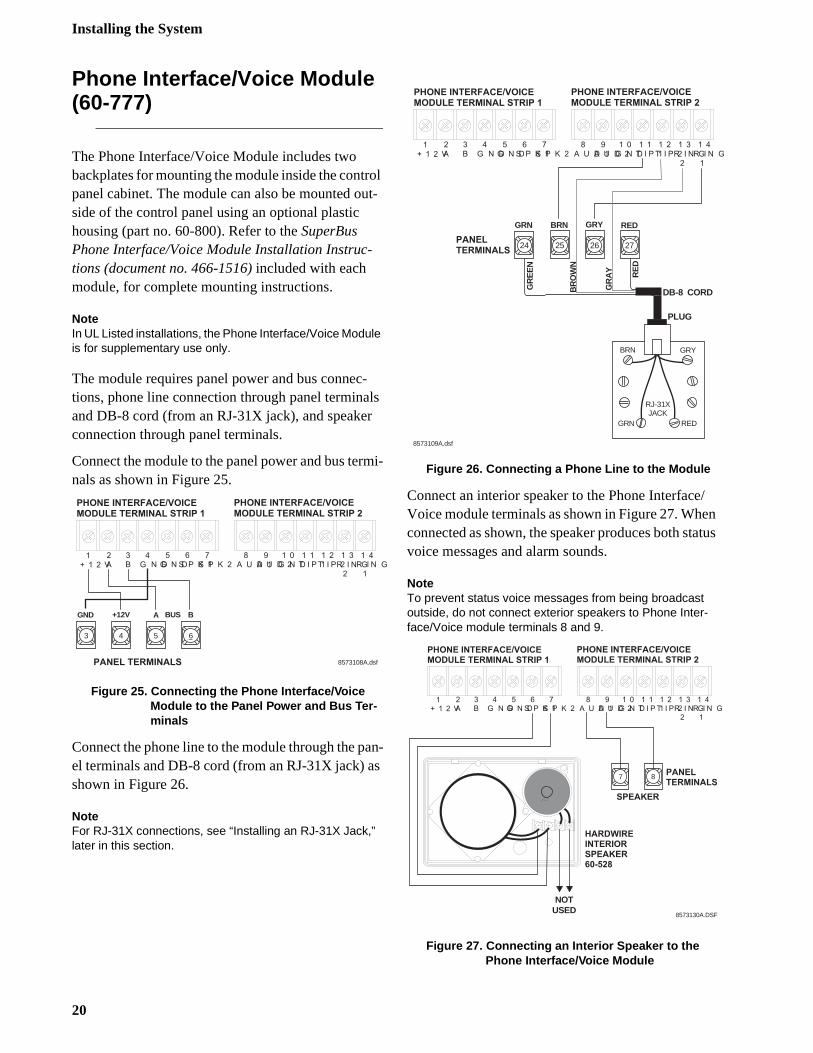
Phone Interface/Voice Module (60-777)
The Phone Interface/Voice Module includes two backplates for mounting the module inside the control panel cabinet. The module can also be mounted out-side of the control panel using an optional plastic housing (part no. 60-800). Refer to the SuperBus Phone Interface/Voice Module Installation Instruc-tions (document no. 466-1516) included with each module, for complete mounting instructions.
NoteIn UL Listed installations, the Phone Interface/Voice Module is for supplementary use only.
The module requires panel power and bus connec-tions, phone line connection through panel terminals and DB-8 cord (from an RJ-31X jack), and speaker connection through panel terminals.
Connect the module to the panel power and bus termi-nals as shown in Figure 25.
Figure 25. Connecting the Phone Interface/Voice Module to the Panel Power and Bus Ter-minals
Connect the phone line to the module through the pan-el terminals and DB-8 cord (from an RJ-31X jack) as shown in Figure 26.
NoteFor RJ-31X connections, see “Installing an RJ-31X Jack,” later in this section.
Figure 26. Connecting a Phone Line to the Module
Connect an interior speaker to the Phone InterfaceVoice module terminals as shown in Figure 27. Wheconnected as shown, the speaker produces both stvoice messages and alarm sounds.
NoteTo prevent status voice messages from being broadcast outside, do not connect exterior speakers to Phone Inter-face/Voice module terminals 8 and 9.
Figure 27. Connecting an Interior Speaker to the Phone Interface/Voice Module
8573108A.dsf
P H O N E I N T E R F A C E / V O I C EM O D U L E T E R M I N A L S T R I P 1
P H O N E I N T E R F A C E / V O I C EM O D U L E T E R M I N A L S T R I P 2
1+ 1 2 V
2A
3B
4G N D
5G N D
6S P K 1
7S P K 2
8A U D 1
9A U D 2
1 0G N D
1 1T I P 1
1 2T I P 2
1 3R I N G2
1 4R I N G1
P A N E L T E R M I N A L S
3 4 5 6
+12V A BGND BUS
P H O N E I N T E R F A C E / V O I C EM O D U L E T E R M I N A L S T R I P 1
P H O N E I N T E R F A C E / V O I C EM O D U L E T E R M I N A L S T R I P 2
1+ 1 2 V
2A
3B
4G N D
5G N D
6S P K 1
7S P K 2
8A U D 1
9A U D 2
1 0G N D
1 1T I P 1
1 2T I P 2
1 3R I N G2
1 4R I N G1
P A N E LT E R M I N A L S
8573109A.dsf
BRN GRY
GRN RED
GR
EE
N
BR
OW
N
GR
AY RE
D
DB-8 CORD
25 26 27
GRY RED
RJ-31XJACK
PLUG
24
GRN BRN
8573130A.DSF
P H O N E I N T E R F A C E / V O I C EM O D U L E T E R M I N A L S T R I P 1
P H O N E I N T E R F A C E / V O I C EM O D U L E T E R M I N A L S T R I P 2
1+ 1 2 V
2A
3B
4G N D
5G N D
6S P K 1
7S P K 2
8A U D 1
9A U D 2
1 0G N D
1 1T I P 1
1 2T I P 2
1 3R I N G2
1 4R I N G1
P A N E LT E R M I N A L S
7 8
S P E A K E R
NOTUSED
H A R D W I R EI N T E R I O RS P E A K E R6 0 - 5 2 8
20
Installing the System
e
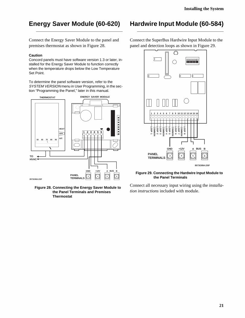
Energy Saver Module (60-620)
Connect the Energy Saver Module to the panel and premises thermostat as shown in Figure 28.
CautionConcord panels must have software version 1.3 or later, in-stalled for the Energy Saver Module to function correctly when the temperature drops below the Low Temperature Set Point.
To determine the panel software version, refer to theSYSTEM VERSION menu in User Programming, in the sec-tion “Programming the Panel,” later in this manual.
Figure 28. Connecting the Energy Saver Module to the Panel Terminals and Premises Thermostat
Hardwire Input Module (60-584)
Connect the SuperBus Hardwire Input Module to thpanel and detection loops as shown in Figure 29.
Figure 29. Connecting the Hardwire Input Module to the Panel Terminals
Connect all necessary input wiring using the installa-tion instructions included with module.
8573G98A.DSF
3 4 5 6
1 2 3 4 5 6
PANELTERMINALS
HEAT
OFF
A/C50 60 70 80 90
THERMOSTAT
TOHVAC
ENERGY SAVER MODULE
+12V A BGND BUS
1 2 3 4 5 6 7 8 9 10 11 12 13 14 15 16
LOO
P 1
CO
MM
ON
LOO
P 2
LOO
P 3
LOO
P 4
CO
MM
ON
LOO
P 5
LOO
P 6
LOO
P 7
LOO
P 8
CO
MM
ON
CO
MM
ON
PANELTERMINALS
8573G99A.DSF
3 4 5 6
+12V A BGND BUS
21
Installing the System
d-
m
to
0. s
g
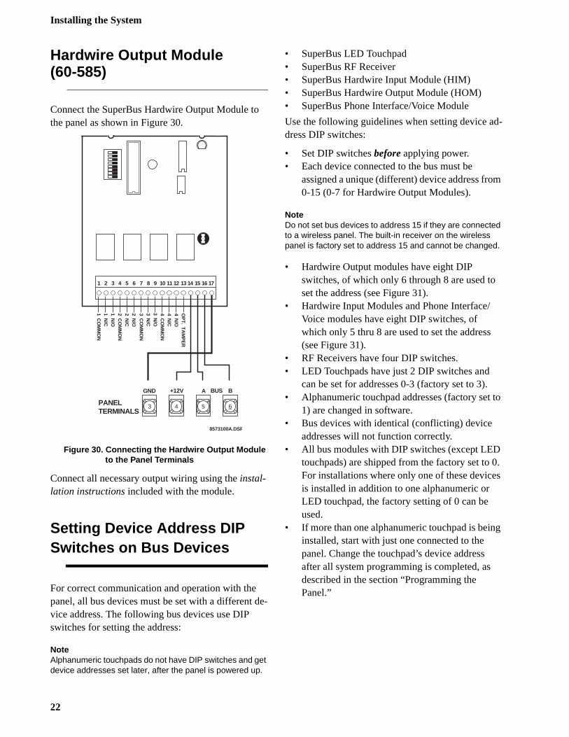
Hardwire Output Module(60-585)
Connect the SuperBus Hardwire Output Module to the panel as shown in Figure 30.
Figure 30. Connecting the Hardwire Output Module to the Panel Terminals
Connect all necessary output wiring using the instal-lation instructions included with the module.
Setting Device Address DIP Switches on Bus Devices
For correct communication and operation with the panel, all bus devices must be set with a different de-vice address. The following bus devices use DIP switches for setting the address:
NoteAlphanumeric touchpads do not have DIP switches and get device addresses set later, after the panel is powered up.
• SuperBus LED Touchpad• SuperBus RF Receiver• SuperBus Hardwire Input Module (HIM)• SuperBus Hardwire Output Module (HOM)• SuperBus Phone Interface/Voice Module
Use the following guidelines when setting device adress DIP switches:
• Set DIP switches before applying power.• Each device connected to the bus must be
assigned a unique (different) device address fro0-15 (0-7 for Hardwire Output Modules).
NoteDo not set bus devices to address 15 if they are connected to a wireless panel. The built-in receiver on the wireless panel is factory set to address 15 and cannot be changed.
• Hardwire Output modules have eight DIP switches, of which only 6 through 8 are used toset the address (see Figure 31).
• Hardwire Input Modules and Phone Interface/Voice modules have eight DIP switches, of which only 5 thru 8 are used to set the address(see Figure 31).
• RF Receivers have four DIP switches.• LED Touchpads have just 2 DIP switches and
can be set for addresses 0-3 (factory set to 3).• Alphanumeric touchpad addresses (factory set
1) are changed in software.• Bus devices with identical (conflicting) device
addresses will not function correctly.• All bus modules with DIP switches (except LED
touchpads) are shipped from the factory set to For installations where only one of these deviceis installed in addition to one alphanumeric or LED touchpad, the factory setting of 0 can be used.
• If more than one alphanumeric touchpad is beininstalled, start with just one connected to the panel. Change the touchpad’s device address after all system programming is completed, as described in the section “Programming the Panel.”
1 CO
MM
ON
1 N/C
1 N/O
2 CO
MM
ON
2 N/O
2 N/C
3 CO
MM
ON
3 N/O
4 CO
MM
ON
4 N/O
4 N/C
3 N/C
PANELTERMINALS
8573100A.DSF
3 4 5 6
+12V A BGND
1 2 3 4 5 6 7 8 9 10 11 12 13 14 15 16 17
OP
T. TAM
PE
RBUS
22
Installing the System
-n-
a-s
e. e in
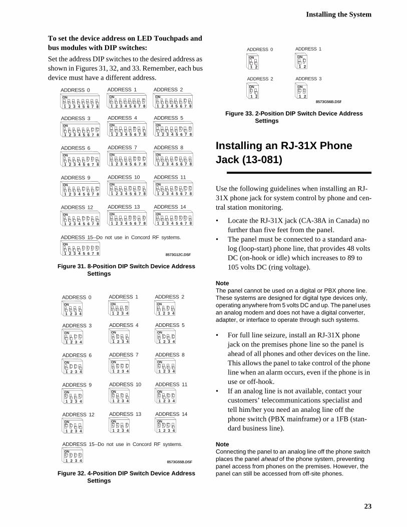
To set the device address on LED Touchpads and bus modules with DIP switches:
Set the address DIP switches to the desired address as shown in Figures 31, 32, and 33. Remember, each bus device must have a different address.
Figure 31. 8-Position DIP Switch Device Address Settings
Figure 32. 4-Position DIP Switch Device Address Settings
Figure 33. 2-Position DIP Switch Device Address Settings
Installing an RJ-31X Phone Jack (13-081)
Use the following guidelines when installing an RJ31X phone jack for system control by phone and cetral station monitoring.
• Locate the RJ-31X jack (CA-38A in Canada) nofurther than five feet from the panel.
• The panel must be connected to a standard anlog (loop-start) phone line, that provides 48 voltDC (on-hook or idle) which increases to 89 to 105 volts DC (ring voltage).
NoteThe panel cannot be used on a digital or PBX phone line. These systems are designed for digital type devices only, operating anywhere from 5 volts DC and up. The panel uses an analog modem and does not have a digital converter, adapter, or interface to operate through such systems.
• For full line seizure, install an RJ-31X phone jack on the premises phone line so the panel isahead of all phones and other devices on the linThis allows the panel to take control of the phonline when an alarm occurs, even if the phone is use or off-hook.
• If an analog line is not available, contact your customers’ telecommunications specialist and tell him/her you need an analog line off the phone switch (PBX mainframe) or a 1FB (stan-dard business line).
NoteConnecting the panel to an analog line off the phone switch places the panel ahead of the phone system, preventing panel access from phones on the premises. However, the panel can still be accessed from off-site phones.
8573G12C.DSF
ADDRESS 0
1 2 3 4 5 6 7 8
ON
ADDRESS 1
1 2 3 4 5 6 7 8
ON
ADDRESS 2
1 2 3 4 5 6 7 8
ON
ADDRESS 3
1 2 3 4 5 6 7 8
ON
ADDRESS 4
1 2 3 4 5 6 7 8
ON
ADDRESS 5
1 2 3 4 5 6 7 8
ON
ADDRESS 6
1 2 3 4 5 6 7 8
ON
ADDRESS 7
1 2 3 4 5 6 7 8
ON
ADDRESS 8
1 2 3 4 5 6 7 8
ON
ADDRESS 9
1 2 3 4 5 6 7 8
ON
ADDRESS 10
1 2 3 4 5 6 7 8
ON
ADDRESS 11
1 2 3 4 5 6 7 8
ON
ADDRESS 12
1 2 3 4 5 6 7 8
ON
ADDRESS 13
1 2 3 4 5 6 7 8
ON
ADDRESS 14
1 2 3 4 5 6 7 8
ON
1 2 3 4 5 6 7 8
ON
ADDRESS 15--Do not use in Concord RF systems.
8573G55B.DSF
ADDRESS 0
1 2 3 4
ON
ADDRESS 1
1 2 3 4
ON
ADDRESS 2
1 2 3 4
ON
ADDRESS 3
1 2 3 4
ON
ADDRESS 4
1 2 3 4
ON
ADDRESS 5
1 2 3 4
ON
ADDRESS 6
1 2 3 4
ON
ADDRESS 7
1 2 3 4
ON
ADDRESS 8
1 2 3 4
ON
ADDRESS 9
1 2 3 4
ON
ADDRESS 10
1 2 3 4
ON
ADDRESS 11
1 2 3 4
ON
ADDRESS 12
1 2 3 4
ON
ADDRESS 13
1 2 3 4
ON
ADDRESS 14
1 2 3 4
ON
ADDRESS 15--Do not use in Concord RF systems.
1 2 3 4
ON
8573G56B.DSF
ADDRESS 0
1 2
ON
ADDRESS 1
1 2
ON
ADDRESS 2
1 2
ON
ADDRESS 3
1 2
ON
23
Installing the System
n-n-e
or
,
e
e .
-
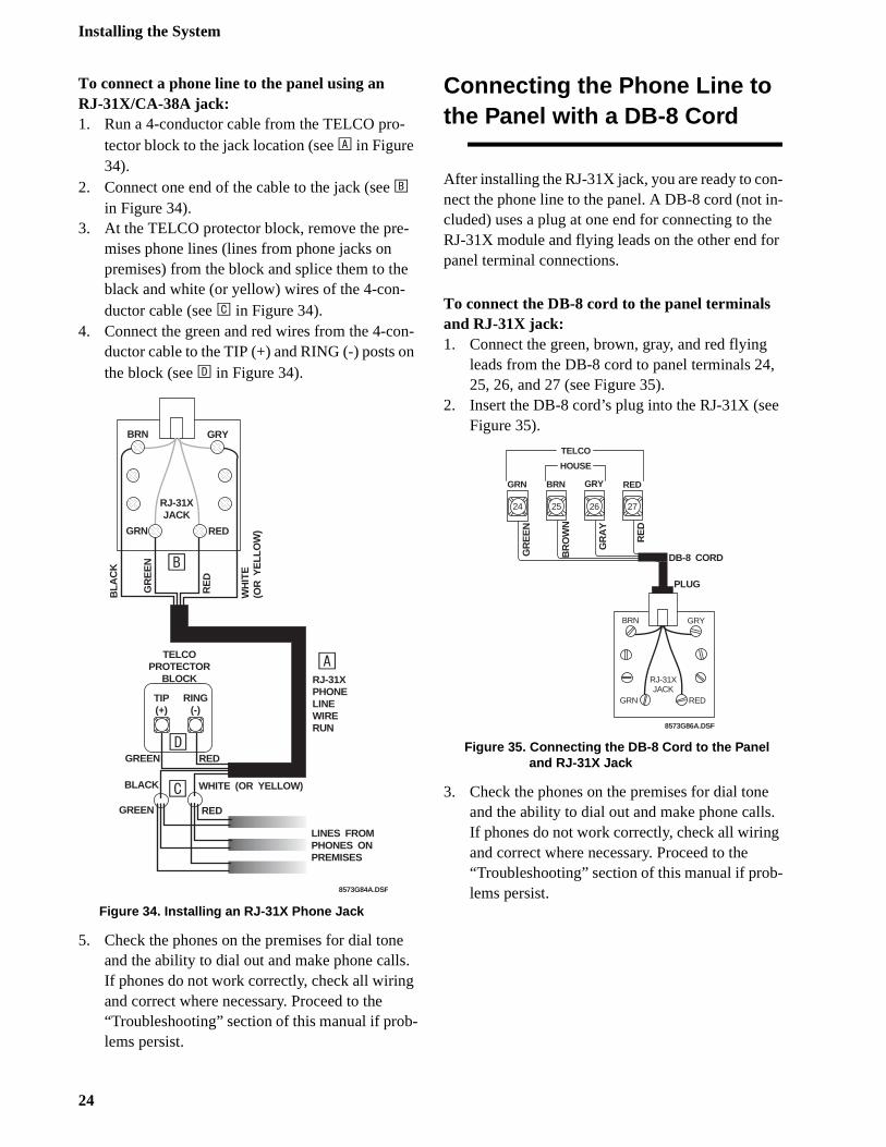
To connect a phone line to the panel using anRJ-31X/CA-38A jack:1. Run a 4-conductor cable from the TELCO pro-
tector block to the jack location (see A in Figure 34).
2. Connect one end of the cable to the jack (see B in Figure 34).
3. At the TELCO protector block, remove the pre-mises phone lines (lines from phone jacks on premises) from the block and splice them to the black and white (or yellow) wires of the 4-con-ductor cable (see C in Figure 34).
4. Connect the green and red wires from the 4-con-ductor cable to the TIP (+) and RING (-) posts on the block (see D in Figure 34).
Figure 34. Installing an RJ-31X Phone Jack
5. Check the phones on the premises for dial tone and the ability to dial out and make phone calls. If phones do not work correctly, check all wiring and correct where necessary. Proceed to the “Troubleshooting” section of this manual if prob-lems persist.
Connecting the Phone Line to the Panel with a DB-8 Cord
After installing the RJ-31X jack, you are ready to conect the phone line to the panel. A DB-8 cord (not icluded) uses a plug at one end for connecting to thRJ-31X module and flying leads on the other end fpanel terminal connections.
To connect the DB-8 cord to the panel terminals and RJ-31X jack:1. Connect the green, brown, gray, and red flying
leads from the DB-8 cord to panel terminals 2425, 26, and 27 (see Figure 35).
2. Insert the DB-8 cord’s plug into the RJ-31X (seFigure 35).
Figure 35. Connecting the DB-8 Cord to the Panel and RJ-31X Jack
3. Check the phones on the premises for dial tonand the ability to dial out and make phone callsIf phones do not work correctly, check all wiringand correct where necessary. Proceed to the “Troubleshooting” section of this manual if problems persist.
BRN GRY
GRN RED
RE
D
WH
ITE
(OR
YE
LLO
W)
BLA
CK
8573G84A.DSF
TELCOPROTECTOR
BLOCK
GREEN RED
RING(-)
RJ-31XPHONELINEWIRERUN
GREEN RED
TIP(+)
LINES FROMPHONES ONPREMISES
RJ-31XJACK
GR
EE
N
BLACK WHITE (OR YELLOW)
A
B
C
D
TELCO
BRN GRY
GRN RED
GR
EE
N
BR
OW
N
GR
AY
RE
D
DB-8 CORD
25 26 27
HOUSE
GRY RED
RJ-31XJACK
PLUG
8573G86A.DSF
24
GRN BRN
24
Installing the System
ed
the
it
s-
Connecting the AC PowerTransformer
The panel must be powered by a plug-in stepdown transformer that supplies 24 VAC, 30 VA (60-761) or 24 VAC, 50 VA (60-778).
For systems that include a Power Line Carrier card, Supervised Wireless Sirens, and X-10 Lamp Mod-ules, the panel must be powered with the Line Carrier Power Transformer that supplies 24 VAC, 30 VA (60-762) or 24 VAC, 50 VA (60-779).
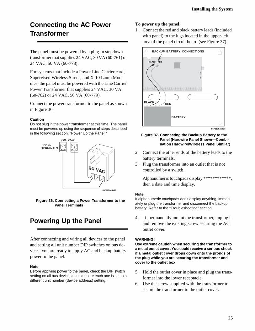
Connect the power transformer to the panel as shown in Figure 36.
CautionDo not plug in the power transformer at this time. The panel must be powered up using the sequence of steps described in the following section, “Power Up the Panel.”
Figure 36. Connecting a Power Transformer to the Panel Terminals
Powering Up the Panel
After connecting and wiring all devices to the panel and setting all unit number DIP switches on bus de-vices, you are ready to apply AC and backup battery power to the panel.
NoteBefore applying power to the panel, check the DIP switch setting on all bus devices to make sure each one is set to a different unit number (device address) setting.
To power up the panel:1. Connect the red and black battery leads (includ
with panel) to the lugs located in the upper-left area of the panel circuit board (see Figure 37).
Figure 37. Connecting the Backup Battery to the Panel (Hardwire Panel Shown—Combi-nation Hardwire/Wireless Panel Similar)
2. Connect the other ends of the battery leads to battery terminals.
3. Plug the transformer into an outlet that is not controlled by a switch.
Alphanumeric touchpads display ************, then a date and time display.
NoteIf alphanumeric touchpads don’t display anything, immedi-ately unplug the transformer and disconnect the backup battery. Refer to the “Troubleshooting” section.
4. To permanently mount the transformer, unplugand remove the existing screw securing the ACoutlet cover.
WARNING!Use extreme caution when securing the transformer to a metal outlet cover. You could receive a serious shock if a metal outlet cover drops down onto the prongs of the plug while you are securing the transformer and cover to the outlet box.
5. Hold the outlet cover in place and plug the tranformer into the lower receptacle.
6. Use the screw supplied with the transformer tosecure the transformer to the outlet cover.
PANELTERMINALS 1 2
24 VAC
8573104A.DSF
BLACK RED
8573106A.DSF
BACKUP BATTERY CONNECTIONS
BATTERY
BLACK RED
25
Programming the Panel
:
,
go
ut ed.
te
Programming the Panel
For on-site system programming, an alphanumeric touchpad is required. All alphanumeric touchpads should have device addresses changed (if the installa-tion includes more than one) before entering program mode.
Setting Alphanumeric Touch-pad Device Addresses
The SuperBus 2x16 Alphanumeric Touchpad device address is factory set to 1 and should not need chang-ing if only one touchpad is installed.
If the system includes more than one of these touch-pads, each one must be assigned a different unit num-ber to work correctly.
The following describes how to set alphanumeric touchpad device addresses.
To set an alphanumeric touchpad device address:1. At the touchpad, press and hold the D and 6 but-
tons together for at least 2 seconds. The display should show DA n, where n is the touchpad’s current address (000 - 015).
NoteAt this time, the touchpad is in configuration mode and no longer communicating to the panel. The system may imme-diately indicate a bus failure. Ignore the failure and continue with the procedure, which will clear after successfully changing the touchpad’s unit number.
2. Press #. The display shows ENTER _.3. Enter the desired three digit device address (000
- 015), then press #. The display shows DA n, where n is the touchpad’s new device address.
4. Press * to exit from the configuration mode.
NoteIf the touchpad’s new unit number was previously learned by the panel, communication between the touchpad and the panel begins immediately. However, if the touchpad’s new unit number has never been learned by the panel, continue with step five.
5. Force the panel to scan bus devices as followsa). For systems where this is the only installed touchpad, remove panel AC and battery powerthen re-apply power.b). For systems with more than one touchpad,
to another system touchpad and enter 8 +
installer CODE (default = 4321) + 0 + 1. The display shows SCANNING BUS DEVICES, then returns to the time and date display.
NoteWhen you change an alphanumeric touchpad device ad-dress, the panel retains the old number in memory. This may cause a bus failure message if the old address is not being used for another bus device. To clear the failure, you must enter program mode and delete the old device ad-dress from panel memory. Refer to the Accessory Mod-ules—Bus Devices—Unit - Type menus described later in this section.
Entering Program Mode
Entering program mode is done using an installer/dealer code (default = 4321). The system can be pinto program mode only when the system is disarm
To enter program mode:1. Make sure the system is disarmed.
2. Press 8 + 4321 + 0 + 0. The touchpad shows SYSTEM PROGRAMMING.
Touchpad Button Program-ming Functions
In program mode, touchpad buttons let you navigato all installer programming menus for configuring the system. Table 6 describes the touchpad buttonfunctions in program mode.
26

Programming the Panel
nly to
ro-ng
ter-ng
1 on e w re
Moving Through Program Mode Tiers and Menus
There are two basic tiers of programming menus. Tier 1 menus are accessible immediately after entering program mode (see Figure 38).
Figure 38. Tier 1 Program Menus
Arrows pointing right represent pressing B to ad-vance forward through the menus. Pressing A moves through the menus in reverse.
The arrow below the System Programming menu rep-resents pressing ƒ to advance to tier 2 programmingmenus. Only when System Programming is displayed can you advance to tier 2 menus (see Figure 39).
Figure 39. Tier 2 Program Menus
Again, arrows pointing right represent pressing B to advance forward through the menus. Pressing A moves through the menus in reverse.
Arrows below each menu represent pressing ƒ to ad-vance to those settings that pertain to that menu. Owhen a specific menu is displayed can you advancethose settings. For example, from the SENSORS menu pressing ƒ gives you access to learning sensors, pgramming sensor text, deleting sensors, and viewisensor programming.
Settings in tier 2 menus can also be accessed by ening shortcut numbers. See the section, “ProgrammiTier 2 Menu Items” for complete details.
Programming Tier 1 Menu Items
This section guides you through programming tier menu items as they appear in sequence. Dependingwhether you’re installing a new system or changingprogramming to an existing system will determine thexact order you need to follow. For example, for neinstallations you should always clear memory befoprogramming any system settings.
Table 6. Alphanumeric Touchpad Button Programming Functions
Button Programming Function
Numeric But-tons
Used to enter numeric values such as menu numbers, delay times and sensor numbers. Also used to enter text character and word codes during sensor text pro-gramming.
A Scrolls backward to previous menu. Dis-plays previous sensor text library charac-ter during sensor text programming.
B Scrolls forward to next menu on current tier. Displays next sensor text library character during sensor text program-ming.
C Used to enter pauses when programming phone numbers.
D Deletes programming for certain menu items.
ƒ Used to move forward to next menu tier, and enter or accept displayed entry.
‚ Cancels and exits displayed programming command (if pressed before #). Backs out to previous menu tier.
#
SystemProgramming
Demo KitOFF/On
Partition 1Copy
Clear MemoryExit
ProgrammingReadyA
B
A
B
A
B
A
B
TIER 1MENUS
B
*
8 5 7 3 1 1 4 A . D S F
TO TIER 2 MENUS
FROM TIER 2 M
ENUS
#
SECURITY PHONESPHONE
OPTIONSTIMERS LIGHT
CONTROLA
B
A
B
A
B
A
B
TIER 2MENUS
A
B
*
8 5 7 3 1 1 5 A . D S F
# * # * # * # *
#
TOUCHPADOPTIONS REPORTING
SIRENOPTIONS SENSORS
AUDIOVERIFICATION
A
B
A
B
A
B
A
B
A
B
* # * # * # * # *
#
ACCESSORYMODULES
ONBOARDOPTIONS
WIRELESSTOUCHPADS
A
B
A
B
A
B
* # * # *FROM SECURITY MENU
TO SECURITY MENU
27
Programming the Panel
r
in o s.
d
-
e m-
3.
Demo Kit Mode (System Programming)
(Default = off) This setting determines whether the panel is used for a standard installation (off) or as a demo kit (on). Turning on this feature and performing a memory clear changes the following settings:
Partition 1 Master Code = 1000
Partition 2 Master Code = 2000
User Code 00 = 1001 (partition 1 code—can also be used to jump to partition 2)
User Code 01 = 1002 (partition 1 code—can also be used to bypass sensors)
User Code 02 = 2001 (partition 2 code—can also be used for remote or off-site access)
User Code 03 = 2002 (partition 2 code—can also be used to perform system tests)
User Code 04 = 1122 (partition 1 code—can also be used to jump to partition 2, for remote or off-site access, and system tests)
User Code 05 = 1122 (partition 2 code—can also be used to jump to partition 1, for remote or off-site access, bypassing sensors, and system tests)
AVM Code = 2121
Partition 1 House Code = 255 (set X-10 modules to P)
Partition 2 House Code = 254 (set X-10 modules to O)
COMM FAILURE = off
Entry Delays = 8 seconds
Exit Delays = 8 seconds
Extended Delays = 1 minute
Siren Timeouts = 2 minutes
Status Beeps = off (all touchpads)
Central Station Reporting = sensors learned into groups 01 and 03, Duress code use, and phone test (8 + CODE + 2)
Energy Saver = functions normally if connected. No Energy Saver connected causes panel to always report temperature as 70° F. Set-ting Freeze Temp (in program mode) above 70 and exiting program mode causes a freeze alarm (if set to on).
To turn Demo Kit Mode off or on:
With the display showing DEMO KIT MODE OFF/ON (current setting), press 1 (off) or 2 (on), then press #.The display flashes the entered setting, then stops after pressing # and displays DEMO KIT MODE OFF/ON (new setting).
Partition 1 Copy (System Programming)
(Default = none) After programming all settings pertain-ing to partition 1, you can make an exact copy to use fopartition 2. This helps reduce programming time when the system is set up for two partitions. If there are certasettings that are unique to partition 2, simply advance tthe appropriate menu and make the necessary change
To Copy Partition 1:
With the display showing PARTITION 1 COPY, press # + installer CODE (default = 4321) + #.The display flashes, then stops after pressing # anshows PARTITION 1 COPY DONE.
Clear Memory (System Programming)
Clearing memory deletes all existing programming information (except the Dealer Code). Clear memory on all newly installed panels before programming.
To Clear Panel Memory:
1. With the system in program mode, press B until the display shows CLEAR MEMORY.
2. Press # and the display shows ENTER CODE TO CLEAR MEMORY.
3. Enter the 4-digit installer CODE (default = 4321) or dealer CODE (if programmed) + #.After about five seconds, the system restarts and thpanel scans the bus to learn all bus device unit nubers.
If the system doesn’t respond as described, repeat step
28
Programming the Panel
-e-
ty
n
ter
Programming Tier 2 Menu Items
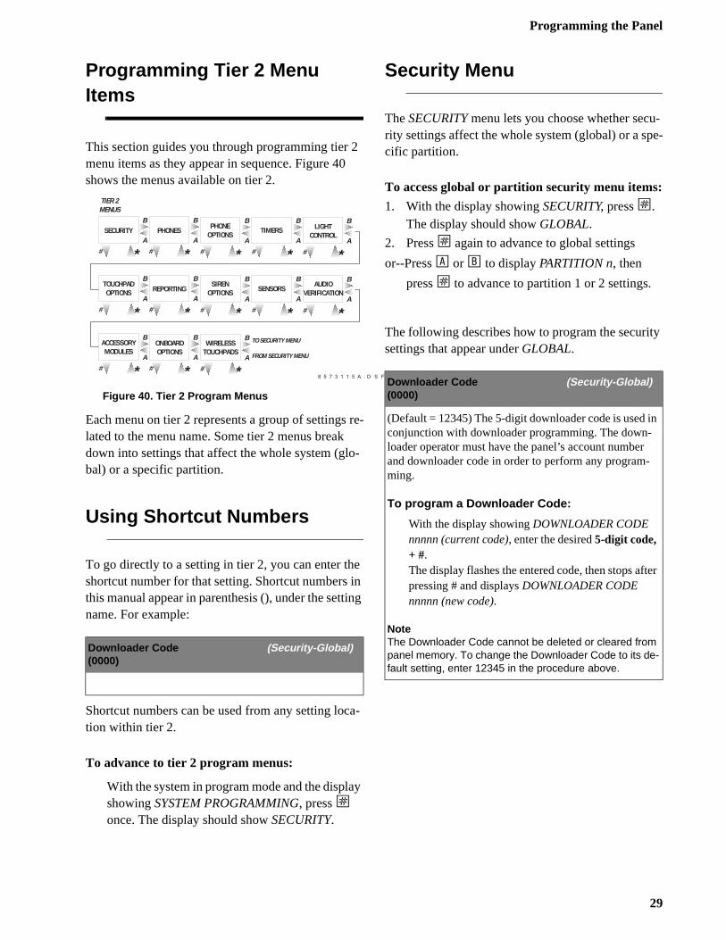
This section guides you through programming tier 2 menu items as they appear in sequence. Figure 40 shows the menus available on tier 2.
Figure 40. Tier 2 Program Menus
Each menu on tier 2 represents a group of settings re-lated to the menu name. Some tier 2 menus break down into settings that affect the whole system (glo-bal) or a specific partition.
Using Shortcut Numbers
To go directly to a setting in tier 2, you can enter the shortcut number for that setting. Shortcut numbers in this manual appear in parenthesis (), under the setting name. For example:
Shortcut numbers can be used from any setting loca-tion within tier 2.
To advance to tier 2 program menus:
With the system in program mode and the display showing SYSTEM PROGRAMMING, press ƒ once. The display should show SECURITY.
Security Menu
The SECURITY menu lets you choose whether security settings affect the whole system (global) or a spcific partition.
To access global or partition security menu items:
1. With the display showing SECURITY, press ƒ. The display should show GLOBAL.
2. Press ƒ again to advance to global settings
or--Press A or B to display PARTITION n, then
press ƒ to advance to partition 1 or 2 settings.
The following describes how to program the securisettings that appear under GLOBAL.
Downloader Code (Security-Global)(0000)
#
SECURITY PHONESPHONE
OPTIONSTIMERS LIGHT
CONTROLA
B
A
B
A
B
A
B
TIER 2MENUS
A
B
*
8 5 7 3 1 1 5 A . D S F
# * # * # * # *
#
TOUCHPADOPTIONS REPORTING
SIRENOPTIONS SENSORS
AUDIOVERIFICATION
A
B
A
B
A
B
A
B
A
B
* # * # * # * # *
#
ACCESSORYMODULES
ONBOARDOPTIONS
WIRELESSTOUCHPADS
A
B
A
B
A
B
* # * # *FROM SECURITY MENU
TO SECURITY MENU
Downloader Code (Security-Global)(0000)
(Default = 12345) The 5-digit downloader code is used iconjunction with downloader programming. The down-loader operator must have the panel’s account numberand downloader code in order to perform any program-ming.
To program a Downloader Code:
With the display showing DOWNLOADER CODE nnnnn (current code), enter the desired 5-digit code, + #.The display flashes the entered code, then stops afpressing # and displays DOWNLOADER CODE nnnnn (new code).
NoteThe Downloader Code cannot be deleted or cleared from panel memory. To change the Downloader Code to its de-fault setting, enter 12345 in the procedure above.
29
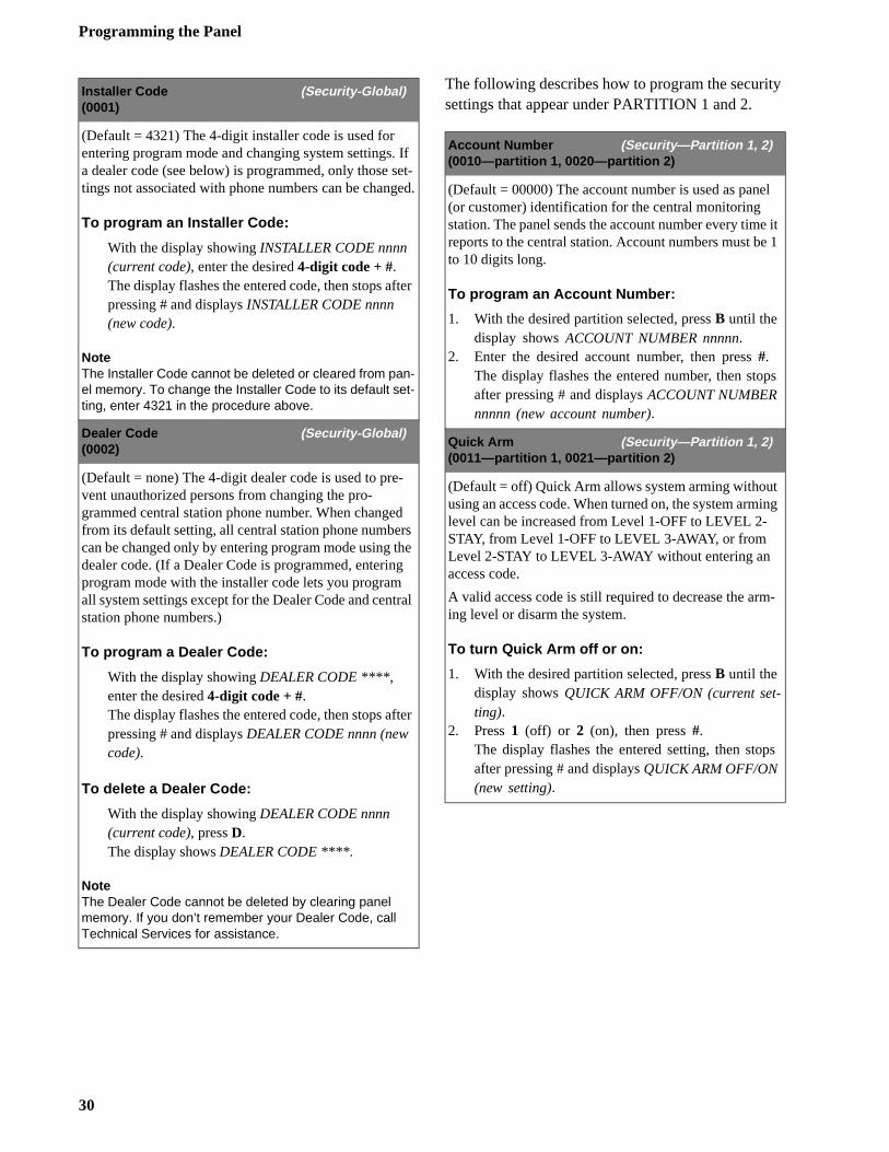
Programming the Panel
y
l
it 1
s
ing
-
s
The following describes how to program the securitsettings that appear under PARTITION 1 and 2.
Installer Code (Security-Global)(0001)
(Default = 4321) The 4-digit installer code is used for entering program mode and changing system settings. If a dealer code (see below) is programmed, only those set-tings not associated with phone numbers can be changed.
To program an Installer Code:
With the display showing INSTALLER CODE nnnn (current code), enter the desired 4-digit code + #.The display flashes the entered code, then stops after pressing # and displays INSTALLER CODE nnnn (new code).
NoteThe Installer Code cannot be deleted or cleared from pan-el memory. To change the Installer Code to its default set-ting, enter 4321 in the procedure above.
Dealer Code (Security-Global)(0002)
(Default = none) The 4-digit dealer code is used to pre-vent unauthorized persons from changing the pro-grammed central station phone number. When changed from its default setting, all central station phone numbers can be changed only by entering program mode using the dealer code. (If a Dealer Code is programmed, entering program mode with the installer code lets you program all system settings except for the Dealer Code and central station phone numbers.)
To program a Dealer Code:
With the display showing DEALER CODE ****, enter the desired 4-digit code + #.The display flashes the entered code, then stops after pressing # and displays DEALER CODE nnnn (new code).
To delete a Dealer Code:
With the display showing DEALER CODE nnnn (current code), press D.The display shows DEALER CODE ****.
NoteThe Dealer Code cannot be deleted by clearing panel memory. If you don’t remember your Dealer Code, call Technical Services for assistance.
Account Number (Security—Partition 1, 2)(0010—partition 1, 0020—partition 2)
(Default = 00000) The account number is used as pane(or customer) identification for the central monitoring station. The panel sends the account number every timereports to the central station. Account numbers must beto 10 digits long.
To program an Account Number:
1. With the desired partition selected, press B until the display shows ACCOUNT NUMBER nnnnn.
2. Enter the desired account number, then press #.The display flashes the entered number, then stopafter pressing # and displays ACCOUNT NUMBER nnnnn (new account number).
Quick Arm (Security—Partition 1, 2)(0011—partition 1, 0021—partition 2)
(Default = off) Quick Arm allows system arming without using an access code. When turned on, the system armlevel can be increased from Level 1-OFF to LEVEL 2-STAY, from Level 1-OFF to LEVEL 3-AWAY, or from Level 2-STAY to LEVEL 3-AWAY without entering an access code.
A valid access code is still required to decrease the arming level or disarm the system.
To turn Quick Arm off or on:
1. With the desired partition selected, press B until the display shows QUICK ARM OFF/ON (current set-ting).
2. Press 1 (off) or 2 (on), then press #.The display flashes the entered setting, then stopafter pressing # and displays QUICK ARM OFF/ON (new setting).
30
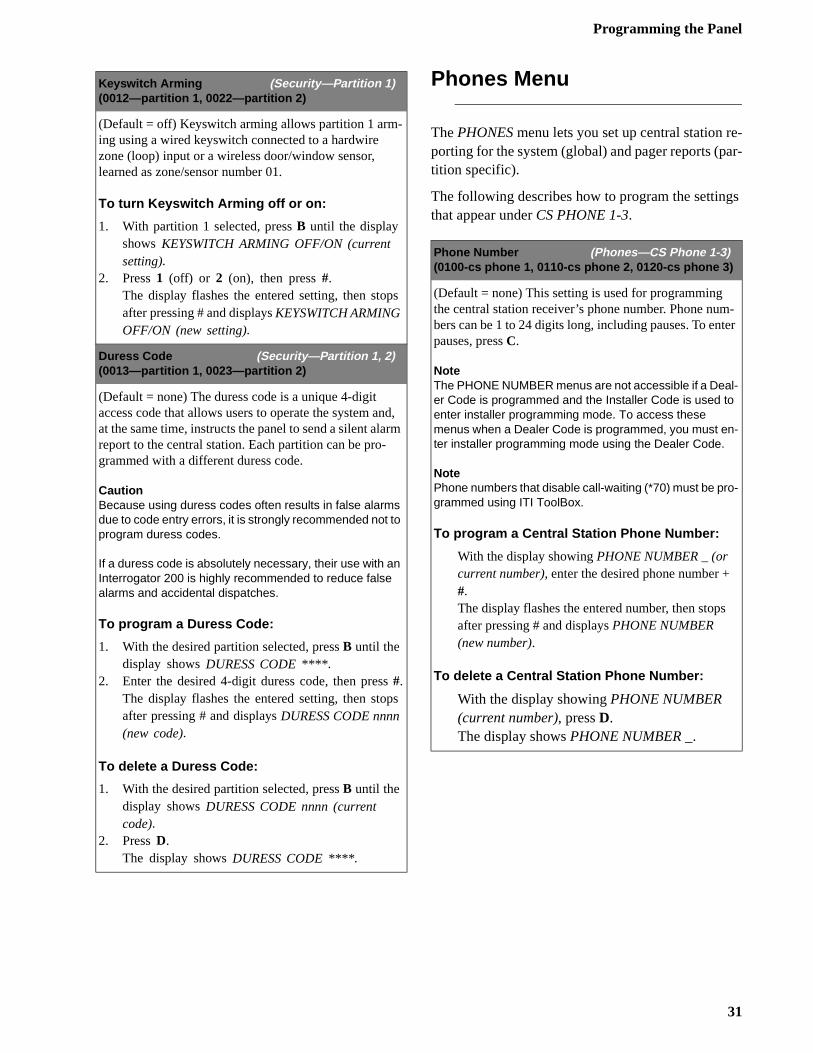
Programming the Panel
e-ar-
s
-er
Phones Menu
The PHONES menu lets you set up central station rporting for the system (global) and pager reports (ptition specific).
The following describes how to program the settingthat appear under CS PHONE 1-3.
Keyswitch Arming (Security—Partition 1)(0012—partition 1, 0022—partition 2)
(Default = off) Keyswitch arming allows partition 1 arm-ing using a wired keyswitch connected to a hardwire zone (loop) input or a wireless door/window sensor, learned as zone/sensor number 01.
To turn Keyswitch Arming off or on:
1. With partition 1 selected, press B until the display shows KEYSWITCH ARMING OFF/ON (current setting).
2. Press 1 (off) or 2 (on), then press #.The display flashes the entered setting, then stops after pressing # and displays KEYSWITCH ARMING OFF/ON (new setting).
Duress Code (Security—Partition 1, 2)(0013—partition 1, 0023—partition 2)
(Default = none) The duress code is a unique 4-digit access code that allows users to operate the system and, at the same time, instructs the panel to send a silent alarm report to the central station. Each partition can be pro-grammed with a different duress code.
CautionBecause using duress codes often results in false alarms due to code entry errors, it is strongly recommended not to program duress codes.
If a duress code is absolutely necessary, their use with an Interrogator 200 is highly recommended to reduce false alarms and accidental dispatches.
To program a Duress Code:
1. With the desired partition selected, press B until the display shows DURESS CODE ****.
2. Enter the desired 4-digit duress code, then press #.The display flashes the entered setting, then stops after pressing # and displays DURESS CODE nnnn (new code).
To delete a Duress Code:
1. With the desired partition selected, press B until the display shows DURESS CODE nnnn (current code).
2. Press D.The display shows DURESS CODE ****.
Phone Number (Phones—CS Phone 1-3)(0100-cs phone 1, 0110-cs phone 2, 0120-cs phone 3)
(Default = none) This setting is used for programming the central station receiver’s phone number. Phone numbers can be 1 to 24 digits long, including pauses. To entpauses, press C.
NoteThe PHONE NUMBER menus are not accessible if a Deal-er Code is programmed and the Installer Code is used to enter installer programming mode. To access these menus when a Dealer Code is programmed, you must en-ter installer programming mode using the Dealer Code.
NotePhone numbers that disable call-waiting (*70) must be pro-grammed using ITI ToolBox.
To program a Central Station Phone Number:
With the display showing PHONE NUMBER _ (or current number), enter the desired phone number + #.The display flashes the entered number, then stopsafter pressing # and displays PHONE NUMBER (new number).
To delete a Central Station Phone Number:
With the display showing PHONE NUMBER (current number), press D.The display shows PHONE NUMBER _.
31
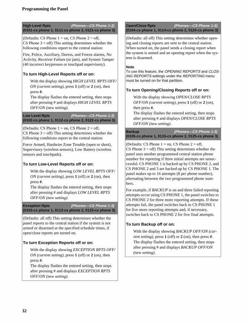
Programming the Panel
-
ys-
d e
to e
High Level Rpts (Phones—CS Phone 1-3)(0101-cs phone 1, 0111-cs phone 2, 0121-cs phone 3)
(Defaults: CS Phone 1 = on, CS Phone 2 = off,CS Phone 3 = off) This setting determines whether the following conditions report to the central station:
Fire, Police, Auxiliary, Duress, and Freeze alarms, No Activity, Receiver Failure (or jam), and System Tamper (40 incorrect keypresses or touchpad supervisory).
To turn High-Level Reports off or on:
With the display showing HIGH LEVEL RPTS OFF/ON (current setting), press 1 (off) or 2 (on), then press #.The display flashes the entered setting, then stops after pressing # and displays HIGH LEVEL RPTS OFF/ON (new setting).
Low Level Rpts (Phones—CS Phone 1-3)(0102-cs phone 1, 0112-cs phone 2, 0122-cs phone 3)
(Defaults: CS Phone 1 = on, CS Phone 2 = off,CS Phone 3 = off) This setting determines whether the following conditions report to the central station:
Force Armed, Hardwire Zone Trouble (open or short), Supervisory (wireless sensors), Low Battery (wireless sensors and touchpads).
To turn Low-Level Reports off or on:
With the display showing LOW LEVEL RPTS OFF/ON (current setting), press 1 (off) or 2 (on), then press #.The display flashes the entered setting, then stops after pressing # and displays LOW LEVEL RPTS OFF/ON (new setting).
Exception Rpts (Phones—CS Phone 1-3)(0103-cs phone 1, 0113-cs phone 2, 0123-cs phone 3)
(Defaults: all off) This setting determines whether the panel reports to the central station if the system is not armed or disarmed at the specified schedule times, if open/close reports are turned on.
To turn Exception Reports off or on:
With the display showing EXCEPTION RPTS OFF/ON (current setting), press 1 (off) or 2 (on), then press #.The display flashes the entered setting, then stops after pressing # and displays EXCEPTION RPTS OFF/ON (new setting).
Open/Close Rpts (Phones—CS Phone 1-3)(0104-cs phone 1, 0114-cs phone 2, 0124-cs phone 3)
(Defaults: all off) This setting determines whether opening and closing reports are sent to the central station. When turned on, the panel sends a closing report whenthe system is armed and an opening report when the stem is disarmed.
NoteTo use this feature, the OPENING REPORTS and CLOS-ING REPORTS settings under the REPORTING menu must be turned on for that partition.
To turn Opening/Closing Reports off or on:
With the display showing OPEN/CLOSE RPTS OFF/ON (current setting), press 1 (off) or 2 (on), then press #.The display flashes the entered setting, then stops after pressing # and displays OPEN/CLOSE RPTS OFF/ON (new setting).
Backup (Phones—CS Phone 1-3)(0105-cs phone 1, 0115-cs phone 2, 0125-cs phone 3)
(Defaults: CS Phone 1 = on, CS Phone 2 = off,CS Phone 3 = off) This setting determines whether the panel uses another programmed central station phone number for reporting if three initial attempts are unsuc-cessful. CS PHONE 1 is backed up by CS PHONE 2, anCS PHONE 2 and 3 are backed up by CS PHONE 1. Thpanel makes up to 16 attempts (8 per phone number), alternating between the two programmed phone num-bers.
For example, if BACKUP is on and three failed reporting attempts occur using CS PHONE 1, the panel switches CS PHONE 2 for three more reporting attempts. If thesattempts fail, the panel switches back to CS PHONE 1 for five more reporting attempts and, if necessary, switches back to CS PHONE 2 for five final attempts.
To turn Backup off or on:
With the display showing BACKUP OFF/ON (cur-rent setting), press 1 (off) or 2 (on), then press #.The display flashes the entered setting, then stops after pressing # and displays BACKUP OFF/ON (new setting).
32
Programming the Panel
l d e
The following describes how to program the phone settings that appear under PAGER PHONE 1 thru 5.
SIA/CID Reporting (Phones—CS Phone 1-3)(0106-cs phone 1, 0116-cs phone 2, 0126-cs phone 3)
(Defaults: all CID) This setting determines whether the panel uses the SIA or CID (Contact ID) reporting format for central station communication.
To select SIA or CID reporting:
With the display showing REPORTING FORMAT SIA/CID (current setting), press 1 (for SIA) or 2 (for CID), then press #.The display flashes the entered setting, then stops after pressing # and displays REPORTING FORMAT SIA/CID (new setting).
Phone Number (Phones—Pager Phone 1-5)(0130-pager 1, 0140-pager 2, 0150-pager 3,0160-pager 4, 0170-pager 5)
(Default = none) This setting is used for programming a phone number that communicates to a pager. Phone num-bers can be 1 to 24 digits long and include pauses, call-waiting disable (*70), skylink number, and 7-digit PIN number.
NotePhone numbers that disable call-waiting (*70) must be pro-grammed using ITI ToolBox.
To program a Pager Phone Number:
With the display showing PHONE NUMBER _ (or current number), enter the desired pager phone num-ber including pauses (press C for 3-second pause), then press #.The display flashes the entered number, then stops after pressing # and displays PHONE NUMBER (new number).
To delete a Pager Phone Number:
With the display showing PHONE NUMBER (cur-rent number), press D.The display shows PHONE NUMBER _.
High Level Rpts (Phones—Pager Phone 1-5)(0131-pager 1, 0141-pager 2, 0151-pager 3,0161-pager 4, 0171-pager 5)
(Default = on) This setting determines whether the fol-lowing alarm conditions report to a pager:
Fire, Police, Auxiliary, Duress, and Freeze alarms, No Activity, Receiver Failure (or jam), and System Tamper(40 incorrect keypresses or touchpad supervisory).
To turn High-Level Reports off or on:
With the display showing HIGH LEVEL RPTS OFF/ON (current setting), press 1 (off) or 2 (on), then press #.The display flashes the entered setting, then stops after pressing # and displays HIGH LEVEL RPTS OFF/ON (new setting).
Low Level Rpts (Phones—Pager Phone 1-5)(0132-pager 1, 0142-pager 2, 0152-pager 3,0162-pager 4, 0172-pager 5)
(Default = off) This setting determines whether the fol-lowing non-alarm conditions report to a pager:
Force Armed, Hardwire Zone Trouble (open or short), Supervisory (wireless sensors), Low Battery (wireless sensors and touchpads).
To turn Low-Level Reports off or on:
With the display showing LOW LEVEL RPTS OFF/ON (current setting), press 1 (off) or 2 (on), then press #.The display flashes the entered setting, then stops after pressing # and displays LOW LEVEL RPTS OFF/ON (new setting).
Exception Rpts (Phones—Pager Phone 1-5)(0133-pager 1, 0143-pager 2, 0153-pager 3,0163-pager 4, 0173-pager 5)
(Default = off) This setting determines whether the panereports to a pager if the system is not armed or disarmeat the specified schedule times, if open/close reports arturned on.
To turn Exception Reports off or on:
With the display showing EXCEPTION RPTS OFF/ON (current setting), press 1 (off) or 2 (on), then press #.The display flashes the entered setting, then stops after pressing # and displays EXCEPTION RPTS OFF/ON (new setting).
33
Programming the Panel
The following describes how to program the phonesettings that appear under DOWNLOADER PHONE.
Open/Close Rpts (Phones—Pager Phone 1-5)(0134-pager 1, 0144-pager 2, 0154-pager 3,0164-pager 4, 0174-pager 5)
(Default = off) This setting determines whether opening and closing reports are sent to a pager. When turned on, the panel sends a closing report when the system is armed and an opening report when the system is dis-armed.
NoteTo use this feature, the OPENING REPORTS and CLOS-ING REPORTS settings under the REPORTING menu must be turned on for that partition.
To turn Opening/Closing Reports off or on:
With the display showing OPEN/CLOSE RPTS OFF/ON (current setting), press 1 (off) or 2 (on), then press #.The display flashes the entered setting, then stops after pressing # and displays OPEN/CLOSE RPTS OFF/ON (current setting).
Latchkey Reports (Phones—Pager Phone 1-5)(0135-pager 1, 0145-pager 2, 0155-pager 3,0165-pager 4, 0175-pager 5)
(Default = on) This setting determines whether the panel reports to a pager when the system is armed or disarmed, according to latchkey time scheduling.
To turn Latchkey reports off or on:
With the display showing LATCHKEY REPORTS OFF/ON (current setting), press 1 (off) or 2 (on), then press #.The display flashes the entered setting, then stops after pressing # and displays LATCHKEY REPORTS OFF/ON (new setting).
Streamlining (Phones—Pager Phone 1-5)(0136-pager 1, 0146-pager 2, 0156-pager 3,0166-pager 4, 0176-pager 5)
(Default = on) This setting determines whether the panel includes (off) or excludes (on) the account number when reporting to a pager.
To turn Streamlining off or on:
With the display showing STREAMLINING OFF/ON (current setting), press 1 (off) or 2 (on), then press #.The display flashes the entered setting, then stops after pressing # and displays STREAMLINING OFF/ON (new setting).
Ptn Assignment (Phones—Pager Phone 1-5)(0137-pager 1, 0147-pager 2, 0157-pager 3,0167-pager 4, 0177-pager 5)
(Default = 1) This setting determines the partition that reports to a pager. Both partitions can be assigned to report to a single pager.
To set up Partition Assignments for pager re-porting:
With the display showing PTN ASSIGNMENT 1/2/12 (current setting), press 1 or 2 to select partition 1 or 2 or press 1 and 2 to select both, then press #.The display flashes the entered setting, then stops after pressing # and displays PTN ASSIGNMENT 1/2/12 (new setting).
Phone Number (Downloader Phone)(0180)
(Default = none) This setting is used for programming the phone number of a computer used for programmingthe panel from off-site. Phone numbers can be 1 to 24 digits long, including pauses. To enter pauses, press C.
To program a downloader phone number:
With the display showing PHONE NUMBER (cur-rent number), enter the desired phone number + #.The display flashes the entered number, then stopsafter pressing # and displays PHONE NUMBER (new number).
34
Programming the Panel
el hat -
e
el
Phone Options Menu
The PHONE OPTIONS menu lets you set up system phone access and communications that affect the whole system (global) or a specific partition.
The following describes how to program the phone option settings that appear under GLOBAL.
Phone Test (Phone Options—Global)(0200)
(Default = on) This setting determines if the user can, at any time, test the communication from the panel to the central station or a pager by entering 8 + CODE + 2 (# + 8 + CODE + 2 from a touch-tone phone).
NoteFor U.L. Commercial Listed installations (UL 1610), this feature must be on.
To turn the Phone Test setting off or on:
With the display showing PHONE TEST OFF/ON (current setting), press 1 (off) or 2 (on), then press #.The display flashes the entered setting, then stops after pressing # and displays PHONE TEST OFF/ON (new setting).
Auto Phone Test (Phone Options—Global)(0201)
(Default = off) This setting determines if the panel sends a phone test automatically to the central station or a pager on a predetermined schedule. (Refer to the “Phone Test Freq.” and “Next Phone Test” settings found under TIM-ERS—GLOBAL).
To turn Automatic Phone Test off or on:
With the display showing AUTO PHONE TEST OFF/ON (current setting), press 1 (off) or 2 (on), then press #.The display flashes the entered setting, then stops after pressing # and displays AUTO PHONE TEST OFF/ON (new setting).
Comm Failure (Phone Options—Global)(0202)
(Default = on) This setting determines whether the panactivates trouble beeps to alert users on the premises tcommunication to the central station failed. Failure notification occurs after the third unsuccessful reporting attempt to the central station/pager.
If a Phone Supervision Card (60-789) is installed, failurnotification can occur immediately if inadequate phone line voltage is detected upon the initial dialing attempt.
NoteFor UL Listed installations, Comm Failure must be turned on.
To turn Communication Failure notification off or on:
With the display showing COMM FAILURE OFF/ON (current setting), press 1 (off) or 2 (on), then press #.The display flashes the entered setting, then stops after pressing # and displays COMM FAILURE OFF/ON (new setting).
DTMF Dialing (Phone Options—Global)(0203)
(Default = on) This setting determines whether the panuses DTMF tones (on) or pulse (off) for dialing pro-grammed phone numbers.
To turn DTMF Dialing off or on:
With the display showing DTMF DIALING OFF/ON (current setting), press 1 (off) or 2 (on), then press #.The display flashes the entered setting, then stops after pressing # and displays DTMF DIALING OFF/ON (new setting).
35
Programming the Panel
n
s
en r
rs l.
t-
,
The following describes how to program the phoneoption settings that appear under PARTITION 1 and PARTITION 2.
NoteA Phone Interface/Voice module must be installed for the system to use the settings under PHONE OPTIONS—PAR-TITION 1 and PARTITION 2.
Dialer Abort (Phone Options—Global)(0204)
(Default = on) This setting determines whether users can stop the panel from reporting an intrusion or auxiliary alarm condition to the central station. If dialer abort is on and the user accidently causes an alarm condition, enter-ing 1 + CODE within 30 seconds stops the panel from reporting the alarm, preventing a false dispatch. Fire alarm reports to the central station cannot be aborted.
NoteThe Dialer Abort feature applies only to CS PHONE 1. The 30-second time setting can only be changed using ITI ToolBox.
To turn Dialer Abort off or on:
With the display showing DIALER ABORT OFF/ON (current setting), press 1 (off) or 2 (on), then press #.The display flashes the entered setting, then stops after pressing # and displays DIALER ABORT OFF/ON (new setting).
Pager Delay (Phone Options—Global)(0205)
(Default = 15 seconds) This setting determines how long a report is delayed to a pager (00 - 30 seconds), after the panel dials the pager number.
NoteThe Pager Delay time should not be set below 5 seconds, unless absolutely necessary.
To set the Pager Delay time:
With the display showing PAGER DELAY nn (cur-rent setting), enter a two digit time (00 - 30), then press #.The display flashes the entered setting, then stops after pressing # and displays PAGER DELAY nn (new setting).
Remote Access (Phone Options—Partition 1, 2)(0210—partition 1, 0220—partition 2)
(Default = on) This setting determines whether users caaccess and control the system from an off-site phone.
To turn Remote Access off or on:
1. With the desired partition selected, press B until the display shows REMOTE ACCESS OFF/ON (cur-rent setting).
2. Press 1 (off) or 2 (on), then press #.The display flashes the entered setting, then stopafter pressing # and displays REMOTE ACCESS OFF/ON (new setting).
Ring/Hang/Ring (Phone Options—Partition 1, 2)(0211—partition 1, 0221—partition 2)
(Default = on) This setting determines how the panel picks up (seizes) the phone line for remote access. Whturned on, the user calls the premises, listens for one otwo full rings, hangs up, then calls the premises again within 10-40 seconds of hanging up. The system answeafter the first ring. The “on” setting is recommended if ananswering machine shares the phone line with the pane
When turned off, the user calls the premises and listensfor 12 full rings before the system answers. The “off” seting is recommended if there is no answering machine sharing the phone line with the panel.
To turn Ring/Hang/Ring access off or on:
1. With the desired partition selected, press B until the display shows RING/HANG/RING OFF/ON (cur-rent setting).
2. Press 1 (off) or 2 (on), then press #.The display begins flashing the entered selectionthen stops and displays RING/HANG/RING OFF/ON (new setting).
36
Programming the Panel
ly
hin
s
Hourly Line Test (Phone Options—Partition 1)(0212—partition 1 only)
(Default = off) This setting determines whether the panel checks the phone line voltage every hour.
NoteThe panel must have a Phone Supervision Card (60-789) installed for this feature to work.
To turn Hourly Line Test off or on:
1. With partition 1 selected, press B until the display shows HOURLY LINE TEST OFF/ON (current set-ting).
2. Press 1 (off) or 2 (on), then press #.The display flashes the entered setting, then stops after pressing # and displays HOURLY LINE TEST OFF/ON (new setting).
Toll Saver (Phone Options—Partition 1, 2)(0213—partition 1, 0223—partition 2)
(Default = on) This setting determines whether the panel answers off-site access on the eighth ring (on) or twelfth ring (off), if a trouble condition exists.
To turn Toll Saver off or on:
1. With the desired partition selected, press B until the display shows TOLL SAVER OFF/ON (current set-ting).
2. Press 1 (off) or 2 (on), then press #.The display flashes the entered setting, then stops after pressing # and displays TOLL SAVER OFF/ON (new setting).
Phone Panic (Phone Options—Partition 1, 2)(0214—partition 1, 0224—partition 2)
(Default = off) This setting determines whether a police panic alarm can be activated from a touch-tone phone. When turned on, pressing ƒ + ‚‚‚‚‚‚ activates a police panic alarm.
To turn Phone Panic off or on:
1. With the desired partition selected, press B until the display shows PHONE PANIC OFF/ON (current setting).
2. Press 1 (off) or 2 (on), then press #.The display flashes the entered setting, then stops after pressing # and displays PHONE PANIC OFF/ON (new setting).
Phone Acc. Key (Phone Options—Partition1, 2)(0215—partition 1, 0225—partition 2)
(Default = ƒ) This setting determines which touch-tonephone button is used for system access and control (onif a Phone Interface and Voice module is installed). To access the system, the user picks up the phone and witfive seconds presses ƒ. The panel seizes the phone line and waits for the user to enter security system com-mands. Phone access can be changed from ƒ to ‚.
NoteTo keep conflicts between the security system and other phone devices and services to a minimum, it is strongly recommended not to change the phone access to ‚. Since many phone devices (answering machines, comput-er modems, fax machines) and services (call-waiting, call-forwarding, banking transactions) require ‚ to initiate their operation, ƒ is set as the default to help reduce con-flicts.
To change the Phone Access Key:
1. With the desired partition selected, press B until the
display shows PHONE ACCESS ƒ/‚ (current setting).
2. Press 1 (for ‚) or 2 (for ƒ), then press #.The display flashes the entered setting, then stop
after pressing # and displays PHONE ACCESS ƒ/
‚ (new setting).
37
Programming the Panel
ne n
ort
, m-
e
Timers Menu
The TIMERS menu lets you set up the various system feature times that affect the whole system (global) or a specific partition.
The following describes how to program the timer settings that appear under GLOBAL.
Supervisory Time (Timers—Global)(0300)
(Default = random from 01:00 to 05:00) This setting determines what time of day the panel reports supervi-sory and low battery reports to the central station. The setting is based on a 24-hour timer so a.m. and p.m. set-tings are not needed.
NoteThe panel’s clock must be set with the correct time for ac-curate supervisory time reporting. Refer to the “User Pro-gramming” section for setting the panel’s clock.
To set the Supervisory Time:
With the display showing SUPERVISORY TIME HH:MM (current setting), enter the desired 4-digit time value (for example, enter 0130 to set the super-visory time for 1:30 a.m.), then press #.The display flashes the entered setting, then stops after pressing # and displays SUPERVISORY TIME (new setting).
RF Tx Timeout (Timers—Global)(0301)
(Default = 12 hours) This setting determines how many hours (2 - 24) the panel has to receive at least one signal from a wireless sensor (learned into a supervised group). If the panel does not receive a signal from any supervised wireless sensor within the set time, the panel reports a supervisory condition to the central station.
NoteFor U.L. Listed commercial installations, the RF Tx Time-out must be set to 4 hours. For U.L. Listed residential in-stallations, the RF Tx Timeout must be set to 24 hours.
To set the RF Tx Timeout:
With the display showing RF TX TIMEOUT nn HOURS (current setting), enter the desired 2-digit timeout value (02 - 24), then press #.The display flashes the entered setting, then stops after pressing # and displays RF TXTIMEOUT nn HOURS (new setting).
Phone Test Freq. (Timers—Global)(0302)
(Default = 07 days) This setting determines how often the panel sends the automatic phone test (see Auto PhoTest under Phone Options—Global) to the central statioor a pager. The phone test frequency can be set to repevery 1 to 255 days.
NoteFor U.L. Commercial Listed installations, this feature must be set to 1.
To set the Phone Test Freq:
With the display showing PHONE TEST FREQ nnn DAYS (current setting), enter the 3-digit value (001 - 255), then press #.The display flashes the entered setting, then stops after pressing # and displays PHONE TEST FREQ nnn DAYS (new setting).
Next Phone Test (Timers—Global)(0303)
(Default = 07 days) This setting determines how many days (001 - 255) until the next automatic phone test occurs. When setting up Phone Test Freq. (see above)Next Phone Test must be set to accurately count the nuber of days left in the cycle before the next phone test occurs. This setting should be the same or less than thPhone Test Freq. setting.
NoteFor U.L. Commercial Listed installations, this feature must be set to 1.
To set the Next Phone Test:
With the display showing NEXT PHONE TEST nnn DAYS (current setting), enter the 3-digit value (001 - 255), then press #.The display flashes the entered setting, then stops after pressing # and displays NEXT PHONE TEST nnn DAYS (new setting).
38
Programming the Panel
e d
s
s
The following describes how to program the timer settings that appear under PARTITION 1/2.
Output Trip Time (Timers—Global)(0304)
(Default = 04 seconds) This setting determines how long onboard, SnapCard, and HOM outputs are activated, when configured for a momentary trip.
To set the Output Trip Time:
With the display showing OUTPUT TRIP TIME nn SECONDS (current setting), enter the desired time (1 - 12), then press #.The display flashes the entered setting, then stops after pressing # and displays HOM TRIP TIME nn SECONDS (new setting).
Activity Timeout (Timers—Global)(0305)
(Default = 24 hours) This setting determines how long the system goes (01 - 42 hours) without user interaction and device activation before sending a ‘no activity’ report to the central station.
To set the Activity Timeout:
With the display showing ENTER ACTIVITY TIME-OUT nn HOURS (current setting) enter the desired 2-digit time value (01 - 42), then press #.The display flashes the entered setting, then stops after pressing # and displays ACTIVITY TIMEOUT nn HOURS (new setting).
Daylight Savings (Timers—Global)(0306)
(Default = on) This setting determines whether the panel’s clock automatically adjusts for daylight savings time changes in spring and fall.
To turn Daylight Savings off or on:
With the display showing DAYLIGHT SAVINGS OFF/ON (current setting), press 1 (off) or 2 (on), then press #.The display flashes the entered setting, then stops after pressing # and displays DAYLIGHT SAVINGS OFF/ON (new setting).
Entry Delay (Timers—Partition 1, 2)(0310—partition 1, 0320—partition 2)
(Default = 032 seconds) This setting determines how much time (32 - 240 seconds) the user has to disarm thsystem after entering the premises through a designatedelay door, to avoid causing an alarm.
NoteFor UL Listed residential installations, the Entry Delay must be set to 45 seconds.
To set the Entry Delay:
1. With the desired partition selected, press B until the display shows ENTRY DELAY nnn SECONDS (cur-rent setting).
2. Enter the desired time value, then press #.The display flashes the entered setting, then stopafter pressing # and displays ENTRY DELAY nnn SECONDS (new setting).
Exit Delay (Timers—Partition 1, 2)(0311—partition 1, 0321—partition 2)
(Default = 064 seconds) This setting determines how much time (48 - 184 seconds) the user has to leave thepremises through a designated delay door after armingthe system, to avoid causing an alarm.
NoteFor UL Listed residential installations, the Exit Delay must be set to 60 seconds.
To set the Exit Delay:
1. With the desired partition selected, press B until the display shows EXIT DELAY nnn SECONDS (cur-rent setting).
2. Enter the desired time value, then press #.The display flashes the entered setting, then stopafter pressing # and displays EXIT DELAY nnn SECONDS (new setting).
39
Programming the Panel
-
y
e
Light Control Menu
The LIGHT CONTROL menu lets you set up light activation that affects a specific partition.
The following describes how to program the light control settings that appear under PARTITION 1 and PARTITION 2.
NoteA Power Line Carrier card must be installed on the panel cir-cuit board, the panel must be powered using the Line Carri-er Transformer, and X-10 Powerhouse Lamp Modules installed at desired lamps for light control to work.
Extended Delay (Timers—Partition 1, 2)(0312—partition 1, 0322—partition 2)
(Default = 04 minutes) This setting determines how much time (01 - 08 minutes) the user has to enter or exit the premises through a designated extended delay door, without causing an alarm.
To set the Extended Delay:
1. With the desired partition selected, press B until the display shows EXTENDED DELAY nn MINUTES (current setting).
2. Enter the desired time value, then press #.The display flashes the entered setting, then stops after pressing # and displays EXTENDED DELAY nn MINUTES (new setting).
Siren Timeout (Timers—Partition 1, 2)(0313—partition 1, 0323—partition 2)
(Default = 04 minutes) This setting determines how long sirens sound (01 - 30 minutes) if no one is present to dis-arm the system.
To set the Siren Timeout:
1. With the desired partition selected, press B until the display shows SIREN TIMEOUT nn MINUTES (current setting).
2. Enter the desired time value, then press #.The display flashes the entered setting, then stops after pressing # and displays SIRENTIMEOUT nn MINUTES (new setting).
Entry Lights (Light Control—Partition 1, 2)(0400—partition 1, 0410—partition 2)
(Default = none) This setting determines whether X-10 controlled lights set to numbers 2 - 9 turn on during entrand exit delays.
NoteX-10 Lamp Modules set to 1 always turn on during the en-try and exit delays. X-10 Lamp Modules set to 2 always flash the arming level when arming the system. For exam-ple, lights flash two times when arming to STAY (level 2); three times when arming to AWAY (level 3).
Important!Lamp Modules set to 2 should not be set up as entry lights, since this setting flashes the arming level immediately af-ter arming.
To set the Entry Lights:
1. With the desired partition selected, press B until the display shows ENTRY LIGHTS nnnnnnnn (current setting).
2. Enter the desired light numbers (2 - 9 based on thUNIT dial setting on each X-10 Lamp Module), thenpress #.The display shows ENTRY LIGHTS nnnnnnnn (new setting).
To delete Entry Lights:
Enter any light number that appears on the display,then press #. The number disappears from the dis-play.
40
Programming the Panel
d
l
X i-t , i-
s
Touchpad Options Menu
The TOUCHPAD OPTIONS menu lets you set up touchpad operation that affects the whole system (global) or a specific partition.
The following describes how to program the touchpaoption settings that appear under GLOBAL.
House Code (Light Control—Partition 1, 2)(0401—partition 1, 0411—partition 2)
(Defaults: partition 1 = 01-B; partition 2 = 02-C) This setting determines which Supervised Wireless Sirens and X-10 controlled lights work in a selected partition. The letter that appears after the house code number indicates the necessary HOUSE dial setting for X-10 modules in that partition.
NoteYou must set the partition House Code and the SWS Supv Code (see the SIREN OPTIONS menu) before plugging in Supervised Wireless Sirens.
To set the House Code:
1. With the desired partition selected, press B until the display shows HOUSE CODE nn-x (current set-ting).
2. Enter the desired number (1 - 255), then press #.The display flashes the entered setting, then stops after pressing # and displays HOUSE CODE nn-x (new setting).
RFTP Supervision (Touchpad Options—Global)(0500)
(Default = off) This setting determines whether the panemonitors for and reports supervisory conditions of Wall-mount Wireless Touchpads.
When turned on, the panel monitors Wall-mount Wire-less Touchpads for supervisory signals (based on RF TTimeout setting). If the panel does not receive a supervsory signal from the touchpad within the RF TX Timeousetting or if a low touchpad battery condition is detectedthe system alerts users and reports a supervisory condtion to the central monitoring station.
NoteThe system alerts users if a low battery condition on any wireless touchpad occurs, whether this setting is off or on.
To turn RFTP Supervision off or on:
1. With the desired partition selected, press B until the display shows RFTP SUPERVISION OFF/ON (cur-rent setting).
2. Press 1 (off) or 2 (on), then press #.The display flashes the entered setting, then stopafter pressing # and displays RFTP SUPERVISION OFF/ONN (new setting).
41
Programming the Panel
g #
g #
The following describes how to program the touchpad option settings that appear under PARTITION 1 and PARTITION 2.
Fire Panic (Touchpad Options—Partition 1, 2)(0510—partition 1, 0520—partition 2)
(Default = on) This setting determines whether the fire panic buttons are enabled (on) or disabled (off) on touch-pads for a selected partition.
To change the Fire Panic setting:
1. With the desired partition selected, press B until the display shows FIRE PANIC OFF/ON (current set-ting).
2. Press 1 (off) or 2 (on), then press #. The display flashes the entered setting, then stops after pressing # and displays FIRE PANIC OFF/ON (new setting).
Aux. Panic (Touchpad Options—Partition 1, 2)(0511—partition 1, 0521—partition 2)
(Default = on) This setting determines whether the auxil-iary panic buttons are enabled (on) or disabled (off) on touchpads for a selected partition.
To change the Auxiliary Panic setting:
1. With the desired partition selected, press B until the display shows AUXILIARY PANIC OFF/ON (cur-rent setting).
2. Press 1 (off) or 2 (on), then press #. The display flashes the entered setting, then stops after pressing # and displays AUXILIARY PANIC OFF/ON (new setting).
Police Panic (Touchpad Options—Partition 1, 2)(0512—partition 1, 0522—partition 2)
(Default = on) This setting determines whether the police panic buttons are enabled (on) or disabled (off) on touch-pads for a selected partition.
To change the Police Panic setting:
1. With the desired partition selected, press B until the display shows POLICE PANIC OFF/ON (current setting).
2. Press 1 (off) or 2 (on), then press #. The display flashes the entered setting, then stops after pressing # and displays POLICE PANIC OFF/ON (new set-ting).
KTP Arm (Touchpad Options—Partition 1, 2)(0513—partition 1, 0523—partition 2)
(Default = off) This setting determines whether keychaintouchpads arm the selected partition directly to AWAY with NO DELAY (on) or increments from OFF to STAY, or from STAY to AWAY (off).
To change the Keychain Touchpad Arming set-ting:
1. With the desired partition selected, press B until the display shows KEYCHAIN TOUCHPAD ARM OFF/ON (current setting).
2. Press 1 (off) or 2 (on), then press #. The display flashes the entered setting, then stops after pressinand displays KEYCHAIN TOUCHPAD ARM OFF/ON (new setting).
Star Is No Delay (Touchpad Options—Partition 1, 2)(0514—partition 1, 0524—partition 2)
(Default = off) This setting determines whether the key-chain touchpad star button controls a hardwire output (off) or the NO DELAY feature (on).
To change the Keychain Star Is No Delay setting:
1. With the desired partition selected, press B until the display shows STAR IS NO DELAY OFF/ON (cur-rent setting).
2. Press 1 (off) or 2 (on), then press #. The display flashes the entered setting, then stops after pressinand displays STAR IS NO DELAY OFF/ON (new setting).
42
Programming the Panel
el ry
el r,
l a e-
Reporting Menu
The REPORTING menu lets you set up which system events (global or partition) are reported to the central monitoring station.
The following describes how to program the reporting settings that appear under GLOBAL.
24-Hour Tamper (Reporting—Global)(06000)
(Default = off) This setting determines whether the panel sounds sirens and reports a tamper alarm when wireless sensor tamper switches are activated, even when the sys-tem is disarmed (OFF).
NoteFor U.L. Commercial Listed installations, this feature must be on.
To turn 24-Hour Tamper off or on:
With the display showing 24-HOUR TAMPER OFF/ON (current setting), press 1 (off) or 2 (on), then press #.The display flashes the entered setting, then stops after pressing # and displays 24-HOUR TAMPER OFF/ON (new setting).
Buffer Control (Reporting—Global)(06001)
(Default = off) This setting determines whether all sys-tem events are logged in the buffer (off) or if only open-ing and closing reports are logged in the buffer (on).
To turn Buffer Control off or on:
With the display showing BUFFER CONTROL OFF/ON (current setting), press 1 (off) or 2 (on), then press #.The display flashes the entered setting, then stops after pressing # and displays BUFFER CONTROL OFF/ON (new setting).
Back In Service (Reporting—Global)(06002)
(Default = on) This setting determines whether the panreports to the central station after AC and backup battepower are restored after an extended power outage.
To turn Back In Service reports off or on:
With the display showing BACK IN SERVICE OFF/ON (current setting), press 1 (off) or 2 (on), then press #.The display flashes the entered setting, then stops after pressing # and displays BACK IN SERVICE OFF/ON (new setting).
Low CPU Battery (Reporting—Global)(06003)
(Default = on) This setting determines whether the panreports a low panel battery to the central station or pagebefore shutting down.
To turn Low CPU Battery reports off or on:
With the display showing LOW CPU BATTERY OFF/ON (current setting), press 1 (off) or 2 (on), then press #.The display flashes the entered setting, then stops after pressing # and displays LOW CPU BATTERY OFF/ON (new setting).
Battery Restoral (Reporting—Global)(06004)
(Default = off) This setting determines whether the panereports to the central monitoring station or pager, whenwireless sensor reports to the panel after battery replacment.
To turn Battery Restoral reports off or on:
With the display showing BATTERY RESTORAL OFF/ON (current setting), press 1 (off) or 2 (on), then press #.The display flashes the entered setting, then stops after pressing # and displays BATTERY RESTORAL OFF/ON (new setting).
43
Programming the Panel
l d
or
Buffer Full Rpt (Reporting—Global)(06005)
(Default = off) This setting determines whether the panel sends an event buffer full report to the central monitoring station when the event buffer is nearly full.
To turn Buffer Full Report off or on:
With the display showing BUFFER FULL RPT OFF/ON (current setting), press #.Press 1 (off) or 2 (on), then press #.The display flashes the entered setting, then stops after pressing # and displays BUFFER FULL RPT OFF/ON (new setting).
Zone Restorals (Reporting—Global)(06006)
(Default = off) This setting determines whether the panel reports a restoral to the central monitoring station or pager for wireless or hardwire zones in alarm, before the alarm is canceled.
NoteAs with all ITI panels, hardwire smoke detectors connect-ed to Concord or SnapCard hardwire zones do not send restorals.
To turn Zone Restoral reporting off or on:
With the display showing ZONE RESTORALS OFF/ON (current setting), press 1 (off) or 2 (on), then press #.The display flashes the entered setting, then stops after pressing # and displays ZONE RESTORAL OFF/ON (new setting).
AC Failure (Reporting—Global)(06007)
(Default = off) This setting determines whether the panel reports to the central station after AC power to the panel is out for 15 minutes.
To turn AC Failure reports off or on:
With the display showing AC FAILURE OFF/ON (current setting), press 1 (off) or 2 (on), then press #.The display flashes the entered setting, then stops after pressing # and displays AC FAILURE OFF/ON (new setting).
Receiver Failure (Reporting—Global)(06008)
(Default = off) This setting determines whether the panereports if no wireless sensor signals have been receivefor two hours, or if the receiver is being jammed (con-stant signal).
NoteFor U.L. Listed installations that include wireless devices, this feature must be on.
To turn Receiver Failure reports off or on:
With the display showing RECEIVER FAILURE OFF/ON (current setting), press 1 (off) or 2 (on), then press #.The display flashes the entered setting, then stops after pressing # and displays RECEIVER FAILURE OFF/ON (new setting).
RF Low Bat Rpt (Reporting—Global)(06009)
(Default = weekly) This setting determines whether thepanel reports to the central monitoring station or pager daily or weekly, when a wireless sensor or touchpad reports a low battery condition to the panel.
To set RF Low Battery Report to daily or weekly:
With the display showing RF LOW BAT RPT DAILY/WEEKLY (current setting), press 1 (daily) or 2 (weekly), then press #.The display flashes the entered setting, then stops after pressing # and displays RF LOW BAT RPT DAILY/WEEKLY (new setting).
RF Supv Report (Reporting—Global)(06010)
(Default = weekly) This setting determines whether thepanel reports to the central monitoring station or pager daily or weekly, when the panel detects a wireless senssupervisory condition.
To set RF Supv Report to daily or weekly:
With the display showing RF SUPV REPORT DAILY/WEEKLY (current setting), press 1 (daily) or 2 (weekly), then press #.The display flashes the entered setting, then stops after pressing # and displays RF SUPV REPORT DAILY/WEEKLY (new setting).
44
Programming the Panel
l if
s
d
s
The following describes how to program the settings that appear under REPORTING—PARTITION 1 and PARTITION 2.
Opening Reports (Reporting—Partition 1, 2)(0610—partition 1, 0620—partition 2)
(Default = off) This setting determines whether the panel sends an opening report to the central station or pager, after the partition is disarmed.
NoteTo use this feature, the OPEN/CLOSE REPORTS settings under the PHONES—CS PHONE 1-3 and/or PHONES—PAGER PHONE 1-5 menus must be turned on for the spe-cific CS Phone or Pager Phone number.
To turn Opening Reports off or on:
1. With the desired partition selected, press B until the display shows OPENING REPORTS OFF/ON (cur-rent setting).
2. Press 1 (off) or 2 (on), then press #.The display flashes the entered setting, then stops after pressing # and displays OPENING REPORTS OFF/ON (new setting).
Closing Reports (Reporting—Partition 1, 2)(0611—partition 1, 0621—partition 2)
(Default = off) This setting determines whether the panel sends a closing report to the central station or pager, after the partition is armed.
To turn Closing Reports off or on:
1. With the desired partition selected, press B until the display shows CLOSING REPORTS OFF/ON (cur-rent setting).
2. Press 1 (off) or 2 (on), then press #.The display flashes the entered setting, then stops after pressing # and displays CLOSING REPORTS OFF/ON (new setting).
No Activity (Reporting—Partition 1, 2)(0612—partition 1, 0622—partition 2)
(Default = off) This setting determines whether the panesends a no activity report to the central station or pager,there is no system activity within a preset time period (see TIMERS—ACTIVITY TIMEOUT).
To turn No Activity reports off or on:
1. With the desired partition selected, press B until the display shows NO ACTIVITY OFF/ON (current setting).
2. Press 1 (off) or 2 (on), then press #.The display flashes the entered setting, then stopafter pressing # and displays NO ACTIVITY OFF/ON (new setting).
Duress Option (Reporting—Partition 1, 2)(0613—partition 1, 0623—partition 2)
(Default = off) This setting determines whether the selected partition can be controlled using a programmeduress code (see SECURITY—PARTITION 1/2—DURESS CODE).
CautionBecause user-code entry errors often result in false alarms, it is strongly recommended not to program any du-ress codes.
If a duress code is absolutely necessary, their use with an Interrogator 200 is highly recommended to reduce false alarms and accidental dispatches.
To turn Duress Option off or on:
1. With the desired partition selected, press B until the display shows DURESS OPTION OFF/ON (current setting).
2. Press 1 (off) or 2 (on), then press #.The display flashes the entered setting, then stopafter pressing # and displays DURESS OPTION OFF/ON (new setting).
45
Programming the Panel
s
l
ts ee
s
Force Armed (Reporting—Partition 1, 2)(0614—partition 1, 0624—partition 2)
(Default = off) This setting determines whether the panel reports to the central monitoring station when a sensor/zone is bypassed, directly or indirectly.
NoteAuto Force Armed (when the panel arms itself) always re-ports to the central monitoring station.
NoteFor UL Listed installations, Force Armed must be turned off.
To turn Force Armed off or on:
1. With the desired partition selected, press B until the display shows FORCE ARMED OFF/ON (current setting).
2. Press 1 (off) or 2 (on), then press #.The display flashes the entered setting, then stops after pressing # and displays FORCE ARMED OFF/ON (new setting).
Latchkey Format (Reporting—Partition 1, 2)(0615—partition 1, 0625—partition 2)
(Default = off) This setting determines whether the selected partition is set up for basic (off) or advanced (on) latchkey opening report operation.
Basic:
a). If the partition is armed by entering2 (or 3) + CODE, disarming using a designated latch-key user code within an assigned time schedule sends a page.
or--
b). If the partition is armed by entering2 (or 3) + CODE + 6 (LATCHKEY), disarming using a designated latchkey user code inside or outside ofan assigned time schedule sends a page.
Advanced:If the partition is armed by entering 2 (or 3) + CODE+ 6 (LATCHKEY), disarming using a latchkey desig-nated user code within an assigned time schedule sends a page.
Refer to the User’s Guide for complete Latchkey setup and operation.
To turn Latchkey Format off or on:
1. With the desired partition selected, press B until the display shows LATCHKEY FORMAT OFF/ON (current setting).
2. Press 1 (off—basic) or 2 (on—advanced), then press #.The display flashes the entered setting, then stopafter pressing # and displays LATCHKEY FORMAT OFF/ON (new setting).
Freeze Alarm (Reporting—Partition 1, 2)(0616—partition 1, 0626—partition 2)
(Default = off) This setting determines whether the panereports a freeze alarm to the central station or pager, when the selected partition’s energy saver module deteca temperature that matches a predetermined setting (sBUS DEVICES—UNIT TYPE nn ESM—PARTITION 1/2—FREEZE TEMP).
To turn Freeze Alarm reporting off or on:
1. With the desired partition selected, press B until the display shows FREEZE ALARM OFF/ON (current setting).
2. Press 1 (off) or 2 (on), then press #.The display flashes the entered setting, then stopafter pressing # and displays FREEZE ALARM OFF/ON (new setting).
46
Programming the Panel
i-s
l i-
l p
Siren Options Menu
The SIREN OPTIONS menu lets you set up siren op-eration that affects the whole system (global) or a spe-cific partition.
The following describes how to program the siren op-tion settings that appear under GLOBAL.
Alarm Verify (Reporting—Partition 1, 2)(0617—partition 1, 0627—partition 2)
(Default = off) This setting determines whether the panel goes into alarm and reports after a single sensor/zone trip (off) or waits for a second trip signal (on).
NoteThis setting applies only to sensors/zones learned into groups 10 - 20. If Alarm Verify is set to on, group 18 re-sponds the same as group 17. See “Appendix A, Table A.5: Sensor Group Characteristics.”
To turn Alarm Verify off or on:
1. With the desired partition selected, press B until the display shows ALARM VERIFY OFF/ON (current setting).
2. Press 1 (off) or 2 (on), then press #.The display flashes the entered setting, then stops after pressing # and displays ALARM VERIFY OFF/ON (new setting).
System Tamper (Reporting—Partition 1, 2)(0618—partition 1, 0628—partition 2)
(Default = off) This setting determines whether the armed partition goes into alarm if several incorrect access codes (40 consecutive keypresses) are entered. This set-ting also determines whether the panel reports to the cen-tral station if a bus device stops communicating with the panel.
NoteFor U.L. Commercial Listed installations, this feature must be on.
To change the System Tamper setting:
1. With the desired partition selected, press B until the display shows SYSTEM TAMPER OFF/ON (current setting).
2. Press 1 (off) or 2 (on), then press #. The display flashes the entered setting, then stops after pressing # and displays FIRE PANIC OFF/ON (new setting).
Immediate Beeps (Siren Options—Global)(0700)
(Default = off) This setting determines when the panel activates trouble beeps , once a wireless sensor supervsory condition is detected. When set to off, trouble beepsound within 4 hours for fire (group 26) sensors and within 10 hours for all other sensors.
NoteFor UL Listed installations, this feature must be on.
To turn Immediate Beeps off or on:
With the display showing IMMEDIATE BEEPS OFF/ON (current setting), press 1 (off) or 2 (on), then press #.The display flashes the entered setting, then stops after pressing # and displays IMMEDIATE BEEPS OFF/ON (new setting).
Disable Tr Beeps (Siren Options—Global)(0701)
(Default = off) This setting determines whether the paneactivates trouble beeps when a wireless sensor supervsory condition is detected.
NoteFor UL Listed installations, this feature must be off.
To turn Disable Trouble Beeps off or on:
With the display showing DISABLE TR BEEPS OFF/ON (current setting), press 1 (off) or 2 (on), then press #.The display flashes the entered setting, then stops after pressing # and displays DISABLE TR BEEPS OFF/ON (new setting).
UL 98 Options (Siren Options—Global)(0702)
(Default = off) This setting determines whether the panecomplies with UL 98 requirements (4-hour trouble beeprestart, 4-hour backup battery test, 4-hour smoke (grou26) supervisory zone).
NoteFor UL Listed installations, this feature must be on.
To turn UL 98 Options off or on:
With the display showing UL 98 OPTIONS OFF/ON (current setting), press 1 (off) or 2 (on), then press #.The display flashes the entered setting, then stops after pressing # and displays UL 98 OPTIONS OFF/ON (new setting).
47
Programming the Panel
s
-
.
n-or
r
l 8.
The following describes how to program the settingthat appear under SIREN OPTIONS—PARTITION 1
Sensors Menu
The SENSORS menu gives you access to the following:
• LEARN SENSORS—lets you learn hardwire zones and wireless sensors into panel memoryand assign zones/sensors to specific partitions
• SENSOR TEXT—lets you program sensor text for zone/sensor identification.
• DELETE SENSORS—lets you delete zones/sen-sors from panel memory.
• VIEW SENSORS—lets you see current group, sensor number, text assignments of learned sesors/zones, identifies whether zone is wireless hardwire, and indicates N/C or N/O configura-tion.
The following describes how to program the sensosettings that appear under LEARN SENSORS.
Important!If 2-wire smoke detectors are connected to hardwire zone input 8, the TWO-WIRE SMOKE setting must be turned on before entering the LEARN SENSORS menu. See ON-BOARD OPTIONS—INPUTS later in this section.
SWS Supv Code (Siren Options—Global)(0703)
(Default = 003) This setting determines the system house code number used for supervising wireless sirens.
NoteTo supervise wireless sirens, Concord hardwire panels must include a SuperBus RF Receiver. For all Concord panels, the siren must be learned into sensor group 33 for the system to process radio signals from wireless sirens.
Supervised Wireless Sirens receive signals from the panel through the existing electrical wiring. If sirens fail to receive or process these signals, the siren transmits a wireless signal to the panel/ receiver.
NoteYou must set SWS Supv Code and the partition House Code (see the LIGHT CONTROL menu) before plugging in Supervised Wireless Sirens.
To set the SWS Supv Code:
With the display showing SWS SUPV CODE nnn (current code), enter the desired code (1 - 255), then press #.The display flashes the entered code, then stops after pressing # and displays SWS SUPV CODE nnn (new code).
Global Fire (Siren Options—Global)(0704)
(Default = off) This setting determines whether sirens in both partitions sound (on) if either partition activates a fire alarm.
To turn Global Fire off or on:
With the display showing GLOBAL FIRE OFF/ON (current setting), press 1 (off) or 2 (on), then press #.The display flashes the entered setting, then stops after pressing # and displays GLOBAL FIRE OFF/ON (new setting).
Siren Verify (Siren Options—Partition 1)(0710)
(Default = off) This setting determines whether the panemonitors speakers connected to panel terminals 7 and
NoteFor UL Listed installations, this feature must be on.
To turn Siren Verify off or on:
With the display showing SIREN VERIFY OFF/ON (current setting), press 1 (off) or 2 (on), then press #.The display flashes the entered setting, then stops after pressing # and displays SIREN VERIFY OFF/ON (new setting).
48
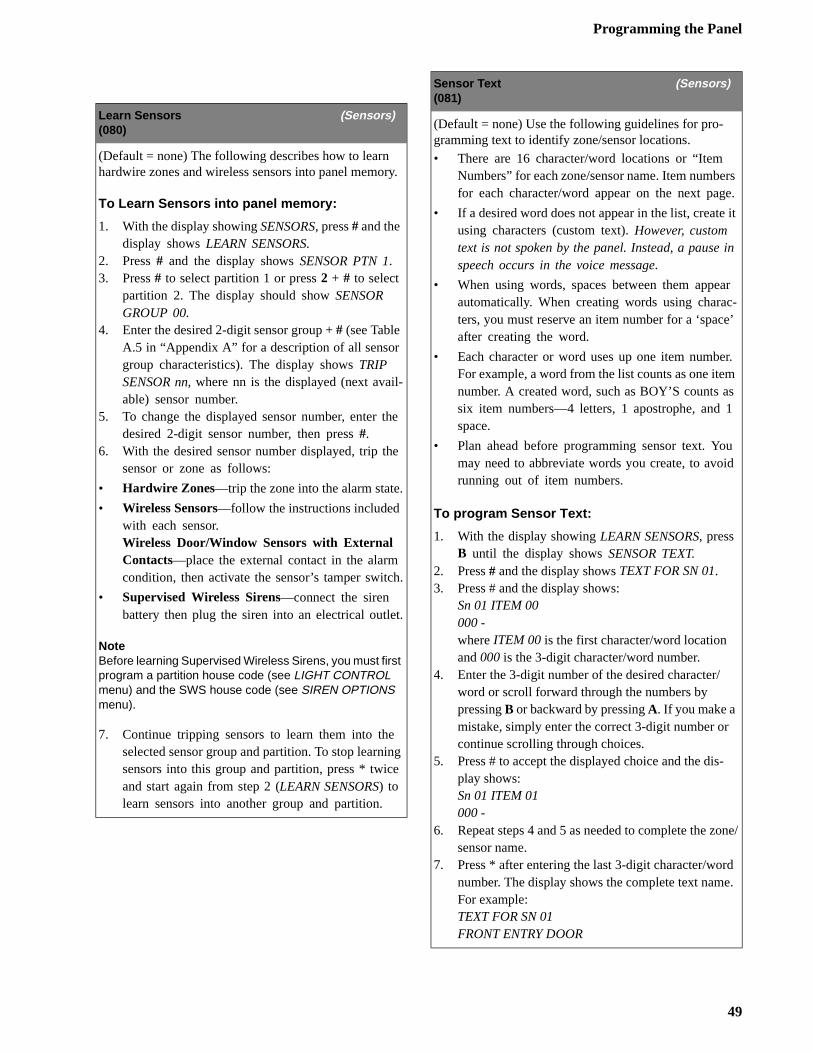
Programming the Panel
rs e.
it
in
r -’
r.
s
u d
-
one/
d .
Learn Sensors (Sensors)(080)
(Default = none) The following describes how to learn hardwire zones and wireless sensors into panel memory.
To Learn Sensors into panel memory:
1. With the display showing SENSORS, press # and the display shows LEARN SENSORS.
2. Press # and the display shows SENSOR PTN 1.3. Press # to select partition 1 or press 2 + # to select
partition 2. The display should show SENSOR GROUP 00.
4. Enter the desired 2-digit sensor group + # (see Table A.5 in “Appendix A” for a description of all sensor group characteristics). The display shows TRIP SENSOR nn, where nn is the displayed (next avail-able) sensor number.
5. To change the displayed sensor number, enter the desired 2-digit sensor number, then press #.
6. With the desired sensor number displayed, trip the sensor or zone as follows:
• Hardwire Zones—trip the zone into the alarm state.
• Wireless Sensors—follow the instructions included with each sensor.Wireless Door/Window Sensors with External Contacts—place the external contact in the alarm condition, then activate the sensor’s tamper switch.
• Supervised Wireless Sirens—connect the siren battery then plug the siren into an electrical outlet.
NoteBefore learning Supervised Wireless Sirens, you must first program a partition house code (see LIGHT CONTROL menu) and the SWS house code (see SIREN OPTIONS menu).
7. Continue tripping sensors to learn them into the selected sensor group and partition. To stop learning sensors into this group and partition, press * twice and start again from step 2 (LEARN SENSORS) to learn sensors into another group and partition.
Sensor Text (Sensors)(081)
(Default = none) Use the following guidelines for pro-gramming text to identify zone/sensor locations.
• There are 16 character/word locations or “Item Numbers” for each zone/sensor name. Item numbefor each character/word appear on the next pag
• If a desired word does not appear in the list, createusing characters (custom text). However, custom text is not spoken by the panel. Instead, a pause speech occurs in the voice message.
• When using words, spaces between them appeaautomatically. When creating words using characters, you must reserve an item number for a ‘spaceafter creating the word.
• Each character or word uses up one item numbeFor example, a word from the list counts as one itemnumber. A created word, such as BOY’S counts asix item numbers—4 letters, 1 apostrophe, and 1space.
• Plan ahead before programming sensor text. Yomay need to abbreviate words you create, to avoirunning out of item numbers.
To program Sensor Text:
1. With the display showing LEARN SENSORS, press B until the display shows SENSOR TEXT.
2. Press # and the display shows TEXT FOR SN 01.3. Press # and the display shows:
Sn 01 ITEM 00000 -where ITEM 00 is the first character/word location and 000 is the 3-digit character/word number.
4. Enter the 3-digit number of the desired character/word or scroll forward through the numbers by pressing B or backward by pressing A. If you make a mistake, simply enter the correct 3-digit number or continue scrolling through choices.
5. Press # to accept the displayed choice and the display shows:Sn 01 ITEM 01000 -
6. Repeat steps 4 and 5 as needed to complete the zsensor name.
7. Press * after entering the last 3-digit character/wornumber. The display shows the complete text nameFor example:TEXT FOR SN 01FRONT ENTRY DOOR
49
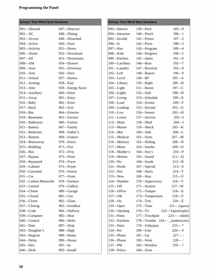
Programming the Panel
)
)
Sensor Text Word Item Numbers
001—Aborted 047—Detector
002—AC 048—Dining
003—Access 049—Disarmed
004—Active 050—Door
005—Activity 051—Down
006—Alarm 052—Download
007—All 053—Downstairs
008—AM 054—Drawer
009—Area 055—Driveway
010—Arm 056—Duct
011—Armed 057—Duress
012—Arming 058—East
013—Attic 059—Energy Saver
014—Auxiliary 060—Enter
015—Away 061—Entry
016—Baby 062—Error
017—Back 063—Exit
018—Bar 064—Exterior
019—Basement 065—Factory
020—Bathroom 066—Failure
021—Battery 067—Family
022—Bedroom 068—Father’s
023—Bottom 069—Feature
024—Breezeway 070—Fence
025—Building 071—Fire
026—Bus 072—First
027—Bypass 073—Floor
028—Bypassed 074—Force
029—Cabinet 075—Foyer
030—Canceled 076—Freeze
031—Car 077—Front
032—Carbon Monoxide 078—Furnace
033—Central 079—Gallery
034—Chime 080—Garage
035—Closed 081—Gas
036—Closet 082—Glass
037—Closing 083—Goodbye
038—Code 084—Hallway
039—Computer 085—Heat
040—Control 086—Hello
041—Date 087—Help
042—Daughter’s 088—High
043—Degrees 089—Home
044—Delay 090—House
045—Den 091—In
046—Desk 092—Install
Sensor Text Word Item Numbers
093—Interior 139—Pool 185—0
094—Intrusion 140—Porch 186—1
095—Invalid 141—Power 187—2
096—Is 142—Press 188—3
097—Key 143—Program 189—4
098—Kids 144—Progress 190—5
099—Kitchen 145—Quiet 191—6
100—Latchkey 146—Rear 192—7
101—Laundry 147—Receiver 193—8
102—Left 148—Report 194—9
103—Level 149—RF 195—A
104—Library 150—Right 196—B
105—Light 151—Room 197—C
106—Lights 152—Safe 198—D
107—Living 153—Schedule 199—E
108—Load 154—Screen 200—F
109—Loading 155—Second 201—G
110—Low 156—Sensor 202—H
111—Lower 157—Service 203—I
112—Main 158—Shed 204—J
113—Master 159—Shock 205—K
114—Mat 160—Side 206—L
115—Medical 161—Siren 207—M
116—Memory 162—Sliding 208—N
117—Menu 163—Smoke 209—O
118—Mother’s 164—Son’s 210—P
119—Motion 165—Sound 211—Q
120—No 166—South 212—R
121—North 167—Special 213—S
122—Not 168—Stairs 214—T
123—Now 169—Stay 215—U
124—Number 170—Supervisory 216—V
125—Off 171—System 217—W
126—Office 172—Tamper 218—X
127—OK 173—Temperature 219—Y
128—On 174—Test 220—Z
129—Open 175—Time 221— (space)
130—Opening 176—To 222—’(apostrophe)
131—Panic 177—Touchpad 223— - (dash
132—Partition 178—Trouble 224— _ (underscore
133—Patio 179—Unbypass 225— *
134—Pet 180—Unit 226— #
135—Phone 181—Up 227— :
136—Please 182—West 228— /
137—PM 183—Window 229— ?
138—Police 184—Zone
50
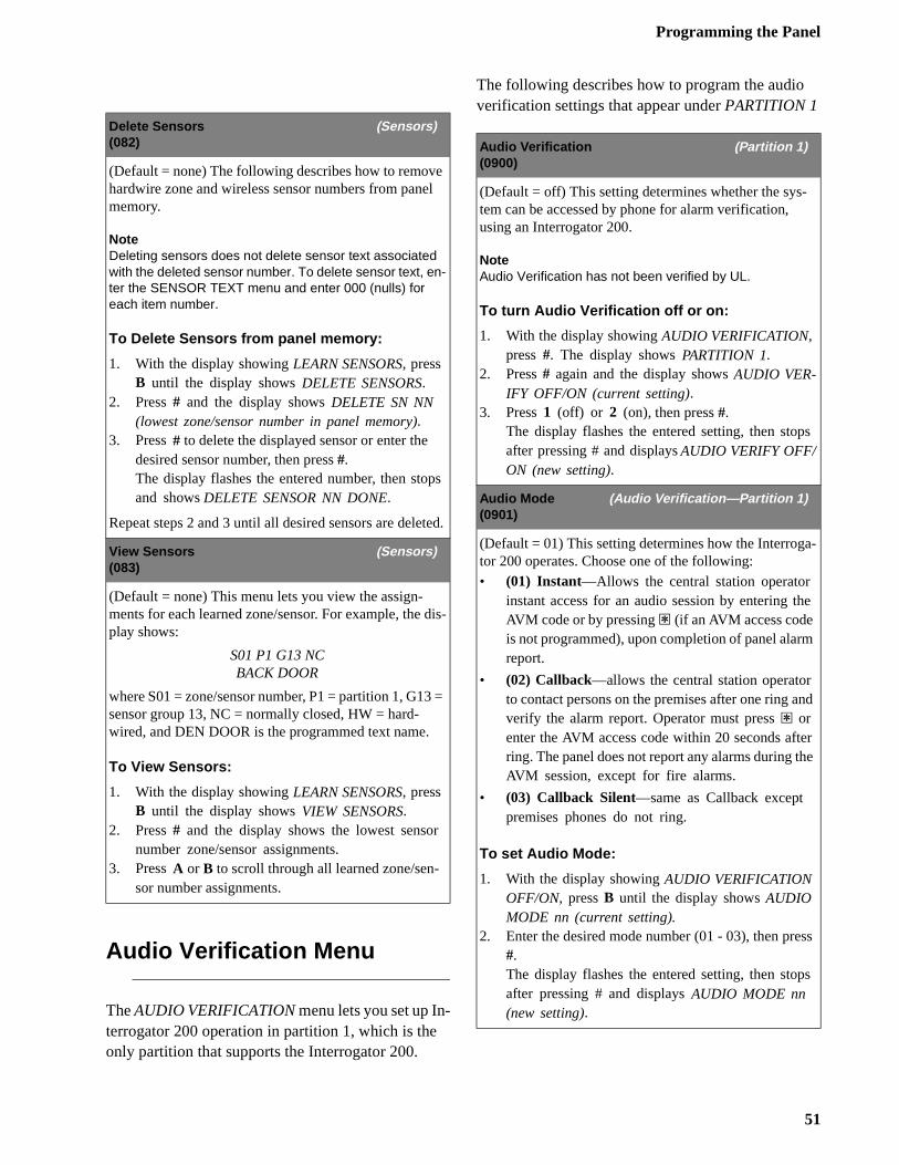
Programming the Panel
s
-
e
nd
r e
ss
s
Audio Verification MenuThe AUDIO VERIFICATION menu lets you set up In-terrogator 200 operation in partition 1, which is the only partition that supports the Interrogator 200.
The following describes how to program the audio verification settings that appear under PARTITION 1
Delete Sensors (Sensors)(082)
(Default = none) The following describes how to remove hardwire zone and wireless sensor numbers from panel memory.
NoteDeleting sensors does not delete sensor text associated with the deleted sensor number. To delete sensor text, en-ter the SENSOR TEXT menu and enter 000 (nulls) for each item number.
To Delete Sensors from panel memory:
1. With the display showing LEARN SENSORS, press B until the display shows DELETE SENSORS.
2. Press # and the display shows DELETE SN NN (lowest zone/sensor number in panel memory).
3. Press # to delete the displayed sensor or enter the desired sensor number, then press #.The display flashes the entered number, then stops and shows DELETE SENSOR NN DONE.
Repeat steps 2 and 3 until all desired sensors are deleted.
View Sensors (Sensors)(083)
(Default = none) This menu lets you view the assign-ments for each learned zone/sensor. For example, the dis-play shows:
S01 P1 G13 NCBACK DOOR
where S01 = zone/sensor number, P1 = partition 1, G13 = sensor group 13, NC = normally closed, HW = hard-wired, and DEN DOOR is the programmed text name.
To View Sensors:
1. With the display showing LEARN SENSORS, press B until the display shows VIEW SENSORS.
2. Press # and the display shows the lowest sensor number zone/sensor assignments.
3. Press A or B to scroll through all learned zone/sen-sor number assignments.
Audio Verification (Partition 1)(0900)
(Default = off) This setting determines whether the sys-tem can be accessed by phone for alarm verification, using an Interrogator 200.
NoteAudio Verification has not been verified by UL.
To turn Audio Verification off or on:
1. With the display showing AUDIO VERIFICATION, press #. The display shows PARTITION 1.
2. Press # again and the display shows AUDIO VER-IFY OFF/ON (current setting).
3. Press 1 (off) or 2 (on), then press #.The display flashes the entered setting, then stopafter pressing # and displays AUDIO VERIFY OFF/ON (new setting).
Audio Mode (Audio Verification—Partition 1)(0901)
(Default = 01) This setting determines how the Interrogator 200 operates. Choose one of the following:• (01) Instant—Allows the central station operator
instant access for an audio session by entering thAVM code or by pressing ‚ (if an AVM access code is not programmed), upon completion of panel alarmreport.
• (02) Callback—allows the central station operator to contact persons on the premises after one ring averify the alarm report. Operator must press ‚ or enter the AVM access code within 20 seconds aftering. The panel does not report any alarms during thAVM session, except for fire alarms.
• (03) Callback Silent—same as Callback except premises phones do not ring.
To set Audio Mode:
1. With the display showing AUDIO VERIFICATION OFF/ON, press B until the display shows AUDIO MODE nn (current setting).
2. Enter the desired mode number (01 - 03), then pre#.The display flashes the entered setting, then stopafter pressing # and displays AUDIO MODE nn (new setting).
51
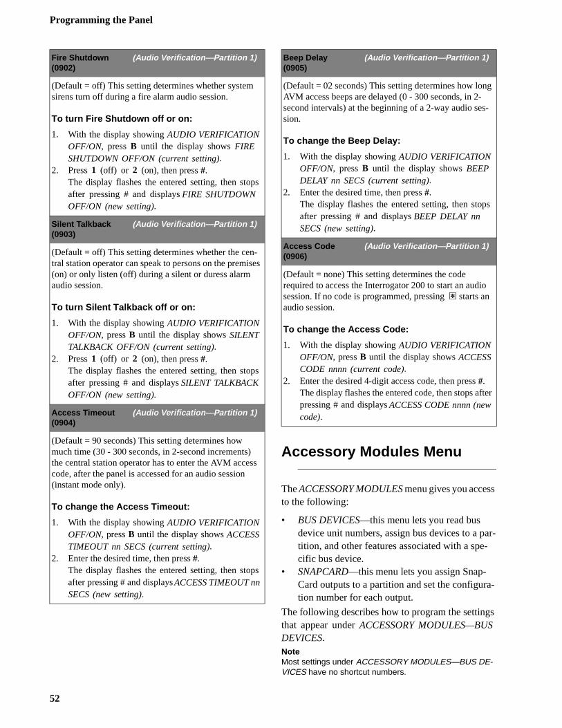
Programming the Panel
ar--
a-
s
g
-
s
o
ter
Accessory Modules Menu
The ACCESSORY MODULES menu gives you accessto the following:
• BUS DEVICES—this menu lets you read bus device unit numbers, assign bus devices to a ptition, and other features associated with a specific bus device.
• SNAPCARD—this menu lets you assign Snap-Card outputs to a partition and set the configurtion number for each output.
The following describes how to program the settingthat appear under ACCESSORY MODULES—BUSDEVICES.NoteMost settings under ACCESSORY MODULES—BUS DE-VICES have no shortcut numbers.
Fire Shutdown (Audio Verification—Partition 1)(0902)
(Default = off) This setting determines whether system sirens turn off during a fire alarm audio session.
To turn Fire Shutdown off or on:
1. With the display showing AUDIO VERIFICATION OFF/ON, press B until the display shows FIRE SHUTDOWN OFF/ON (current setting).
2. Press 1 (off) or 2 (on), then press #.The display flashes the entered setting, then stops after pressing # and displays FIRE SHUTDOWN OFF/ON (new setting).
Silent Talkback (Audio Verification—Partition 1)(0903)
(Default = off) This setting determines whether the cen-tral station operator can speak to persons on the premises (on) or only listen (off) during a silent or duress alarm audio session.
To turn Silent Talkback off or on:
1. With the display showing AUDIO VERIFICATION OFF/ON, press B until the display shows SILENT TALKBACK OFF/ON (current setting).
2. Press 1 (off) or 2 (on), then press #.The display flashes the entered setting, then stops after pressing # and displays SILENT TALKBACK OFF/ON (new setting).
Access Timeout (Audio Verification—Partition 1)(0904)
(Default = 90 seconds) This setting determines how much time (30 - 300 seconds, in 2-second increments) the central station operator has to enter the AVM access code, after the panel is accessed for an audio session (instant mode only).
To change the Access Timeout:
1. With the display showing AUDIO VERIFICATION OFF/ON, press B until the display shows ACCESS TIMEOUT nn SECS (current setting).
2. Enter the desired time, then press #.The display flashes the entered setting, then stops after pressing # and displays ACCESS TIMEOUT nn SECS (new setting).
Beep Delay (Audio Verification—Partition 1)(0905)
(Default = 02 seconds) This setting determines how lonAVM access beeps are delayed (0 - 300 seconds, in 2-second intervals) at the beginning of a 2-way audio session.
To change the Beep Delay:
1. With the display showing AUDIO VERIFICATION OFF/ON, press B until the display shows BEEP DELAY nn SECS (current setting).
2. Enter the desired time, then press #.The display flashes the entered setting, then stopafter pressing # and displays BEEP DELAY nn SECS (new setting).
Access Code (Audio Verification—Partition 1)(0906)
(Default = none) This setting determines the code required to access the Interrogator 200 to start an audisession. If no code is programmed, pressing ‚ starts an audio session.
To change the Access Code:
1. With the display showing AUDIO VERIFICATION OFF/ON, press B until the display shows ACCESS CODE nnnn (current code).
2. Enter the desired 4-digit access code, then press #. The display flashes the entered code, then stops afpressing # and displays ACCESS CODE nnnn (new code).
52
Programming the Panel
d f is-
s
s
.
-
s
s
e
is
n
s
Unit - Type (Acc. Modules—Bus Devices)(1000 thru 1015)
(Default = none) This menu lets you identify all con-nected bus devices, their device address, and lets you set up partition assignment and other configurations based on a specific device. You can also delete learned bus device addresses.
To identify bus device Unit and Type:
1. With the display showing BUS DEVICES, press #. The display identifies the bus device set to unit num-ber 00. For example:UNIT TYPE 00—LTP
2. Press A or B to identify all other bus device unit numbers (0-15) and types (LED Touchpad = LTP, Alphanumeric Touchpad = ATP, Energy Saver Mod-ule = ESM, Hardwire Input Module = HIM, Hard-wire Output Module = HOM, Phone Interface & Voice Module = PIV, SuperBus RF Receiver = RCVR, no device = NONE).
To delete learned bus device unit numbers:
1. With the display showing BUS DEVICES, press #. The display shows the bus device set to unit number 00.
2. Press A or B until the bus device unit number you want to delete is displayed.
3. Press D. The display changes the unit number to NONE.
Ptn Assignment (Acc. Modules—Bus Devices)
(Default = 1) This menu lets you assign bus devices to work in the desired partition.
NoteHardwire Input Modules, Hardwire Output Modules, and SuperBus RF Receivers are not assigned to partitions.
To assign bus devices to partitions:
1. With the display showing the desired bus device, press #. The display shows PARTITION ASSIGN n.
2. Press 1 or 2 to select the desired partition, then press #.The display flashes the entered selection and then stops, confirming the change.
Status Beeps (Acc. Modules—Bus Devices)
(Default = on) This setting determines whether the selected touchpad sounds status beeps. Each touchpacan be set individually. This feature is usually turned ofif a touchpad is located in or near bedrooms, to avoid dturbing persons sleeping.
To turn touchpad Status Beeps on or off:
1. With the display showing the desired touchpad, pres# then B once. The display shows STATUS BEEPS OFF/ON (current setting).
2. Press 1 (off) or 2 (on) to select the desired setting, then press #.The display flashes the entered selection, then stopafter pressing # and shows STATUS BEEPS OFF/ON (new setting).
Key Beeps (Acc. Modules—Bus Devices)
(Default = on) This setting determines whether selectedtouchpads sound beeps when their buttons are pressedThis feature is usually turned off if a touchpad is locatedin or near bedrooms, to avoid disturbing persons sleeping.
To turn Key Beeps on or off:
1. With the display showing the desired touchpad, pres# then B twice. The display shows KEY BEEPS OFF/ON (current setting).
2. Press 1 (off) or 2 (on) to select the desired setting, then press #.The display flashes the entered selection, then stopafter pressing # and shows KEY BEEPS OFF/ON (new setting).
Freeze Temp (Acc. Modules—Bus Devices)
(Default = 42°F) This setting determines the temperaturpoint that the Energy Saver Module detects a potential freeze (heating failure) condition. The adjustable range from 40°F - 90°F.
To change the Freeze Temp setting:
1. With the display showing UNIT nn TYPE ESM, press # then B. The display shows FREEZE TEMP nn DEGREES (current setting).
2. Enter the desired 2-digit temperature (40 - 90), thepress #.The display flashes the entered selection, then stopafter pressing # and shows FREEZE TEMP nn DEGREES (new setting).
53
Programming the Panel
e
s-
set
t
s
Temperature (Acc. Modules—Bus Devices)
(Default = none) This setting lets you adjust the ESM room temperature setting to match the premises thermo-stat. The adjustable range is from 40°F - 90°F.
NoteTo ensure accuracy, wait at least 30 minutes before set-ting the ESM temperature to allow the ESM to warm or cool to actual room temperature.
To change the ESM Temperature setting:
1. With the display showing UNIT nn TYPE ESM, press # then B twice. The display shows TEMPERA-TURE nn DEGREES (current setting).
2. Enter the desired 2-digit temperature (40 - 90), then press #.The display flashes the entered selection, then stops after pressing # and shows TEMPERATURE nn DEGREES (new setting).
Relay 1, 2, 3, 4 (Acc. Modules—Bus Devices)
(Default = none) This setting lets you assign Hardwire Output Module (HOM) relay outputs to partitions and assign the 5-digit configuration number for each relay output, that determines which system event activates thoutput and the duration or time the output is activated.
The first three digits represent the trigger number of anevent such as, an alarm, open sensor, or arming the sytem.
The last two digits represent how the output responds such as, momentary, sustained (or latched), or for a pretime.
Tables 7 - 11 on pages 57 through 60 identify system event trigger and response numbers.
To assign HOM Relay outputs to partitions and set their configuration numbers:
1. With the display showing UNIT nn TYPE HOM, press #. The display shows RELAY 1.
2. Press A or B to select the desired relay (1 - 4), then press #. The display shows PARTITION ASSIGN 1.
3. Press 1 or 2 to select the desired partition assignmenfor this relay, then press #.The display flashes the entered selection, then stopafter pressing # and shows PARTITION ASSIGN n (new setting)
4. Press B and the display shows CONFIGURATION nnnnn (current setting).
5. Enter the desired 5-digit configuration number for this relay, then press #.The display flashes the entered number, then stopsafter pressing # and shows CONFIGURATION nnnnn (new setting).
54
Programming the Panel
fi-
-
s
l
r.
The following describes how to program the settings that appear under SNAPCARDS.
Onboard Options Menu
The ONBOARD OPTIONS menu lets you set up the following built-in options:
INPUTS—this menu lets you set panel zone input 8for 2-wire smoke operation and turn the smoke verication feature off/on.
OUTPUTS—this menu lets you assign the panel’s two built-in outputs to partitions and set their configuration numbers.
The following describes how to program the settingthat appear under ONBOARD OPTIONS—INPUTS.
Relay 1, 2, 3, 4 (Acc. Modules—SnapCards)(101XY where X = relay 1 thru 4; Y = partition/configu-ration number)
(Default = none) This setting lets you assign SnapCard relay outputs to partitions and assign the 5-digit configu-ration number for each relay output, that determines which system event activates the output and the duration or time the output is activated.
The first three digits represent the trigger number of an event such as, an alarm, open sensor, or arming the sys-tem.
The last two digits represent how the output responds such as, momentary, sustained (or latched), or for a preset time.
Tables 7 - 11 on pages 57 through 60 identify system event trigger and response numbers.
To assign SnapCard Relay outputs to partitions and set their configuration numbers:
1. With the display showing SNAPCARDS, press #. The display shows RELAY 1.
2. Press A or B to select the desired relay (1 - 4), then press #. The display shows PARTITION ASSIGN n (current setting).
3. Press 1 or 2 to select the desired partition assignment for this relay, then press #.The display flashes the entered selection, then stops after pressing # and shows PARTITION ASSIGN n (new setting)
4. Press B and the display shows CONFIGURATION nnnnn (current setting).
5. Enter the desired 5-digit configuration number for this relay, then press #.The display flashes the entered number, then stops after pressing # and shows CONFIGURATION nnnnn (new setting).
Smoke Verify (Onboard Options—Inputs)(1100)
(Default = off) This setting determines whether the panerequires two alarm signals within five minutes (on) from2- or 4-wire smoke detectors connected to panel zone input 8 and/or SnapCard zone inputs, before activatingsystem sirens and reporting to a central station or page
NoteFor California State Fire Marshall Listed installations, this feature must be off.
To turn Smoke Verify off or on:
1. With the display showing ONBOARD OPTIONS, press #. The display shows SMOKE VERIFY OFF/ON (current setting).
2. Press 1 (off) or 2 (on), then press #.The display flashes the entered number, then stopsafter pressing # and shows SMOKE VERIFY OFF/ON (new setting).
55
Programming the Panel
-rti-
d
s-
set
ti-
Two-Wire Smoke (Onboard Options—Inputs)(1101)
(Default = off) This setting determines whether panel zone input 8 is set up for 2-wire smoke detectors (on) or for standard intrusion or 4-wire smoke detectors (off).
NoteIf 2-wire smoke detectors are connected to hardwire zone input 8, this setting must be turned on before entering the LEARN SENSORS menu.
To turn Two-Wire Smoke off or on:
1. With the display showing ONBOARD OPTIONS, press #. The display shows TWO WIRE SMOKE OFF/ON (current setting).
2. Press 1 (off) or 2 (on), then press #.The display flashes the entered number, then stops after pressing # and shows TWO WIRE SMOKE OFF/ON (new setting).
Output 1, 2. (Onboard Options—Output 1, 2)(11XY where X = output 1 or 2; Y = partition/configura-tion number)
(Default: Output 1 = 01400, Output 2 = 00410) This setting lets you assign the selected output to a specific pation and assign the 5-digit configuration number that determines which system event activates the output anthe duration or time the output is activated.
The first three digits represent the trigger number of anevent such as, an alarm, open sensor, or arming the sytem.
The last two digits represent how the output responds such as, momentary, sustained (or latched), or for a pretime.
Tables 7 - 11 on pages 57 through 60 identify system event trigger and response numbers.
To set up onboard Output 1 & 2 partition and configuration assignments:
1. With the display showing ONBOARD OPTIONS, press #. The display shows INPUTS.
2. Press A or B to select output 1 or 2, then press #. The display shows PARTITION ASSIGN n (current set-ting).
3. Press 1 or 2 to assign the output to the desired partion, then press #. The display shows PARTITION ASSIGN (new setting).
4. Press B and the display shows CONFIGURATION nnnn (current setting).
5. Enter the desired configuration number, then press#.The display flashes the entered number, then stopsafter pressing # and shows CONFIGURATION nnnnn (new setting).
56
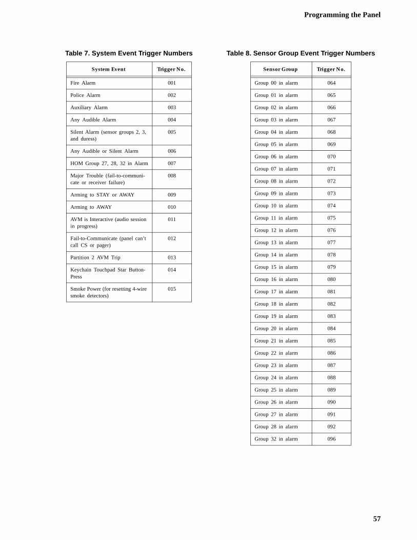
Programming the Panel
Table 7. System Event Trigger Numbers
System Event Trigger No.
Fire Alarm 001
Police Alarm 002
Auxiliary Alarm 003
Any Audible Alarm 004
Silent Alarm (sensor groups 2, 3, and duress)
005
Any Audible or Silent Alarm 006
HOM Group 27, 28, 32 in Alarm 007
Major Trouble (fail-to-communi-cate or receiver failure)
008
Arming to STAY or AWAY 009
Arming to AWAY 010
AVM is Interactive (audio session in progress)
011
Fail-to-Communicate (panel can’t call CS or pager)
012
Partition 2 AVM Trip 013
Keychain Touchpad Star Button-Press
014
Smoke Power (for resetting 4-wire smoke detectors)
015
Table 8. Sensor Group Event Trigger Numbers
Sensor Group Trigger No.
Group 00 in alarm 064
Group 01 in alarm 065
Group 02 in alarm 066
Group 03 in alarm 067
Group 04 in alarm 068
Group 05 in alarm 069
Group 06 in alarm 070
Group 07 in alarm 071
Group 08 in alarm 072
Group 09 in alarm 073
Group 10 in alarm 074
Group 11 in alarm 075
Group 12 in alarm 076
Group 13 in alarm 077
Group 14 in alarm 078
Group 15 in alarm 079
Group 16 in alarm 080
Group 17 in alarm 081
Group 18 in alarm 082
Group 19 in alarm 083
Group 20 in alarm 084
Group 21 in alarm 085
Group 22 in alarm 086
Group 23 in alarm 087
Group 24 in alarm 088
Group 25 in alarm 089
Group 26 in alarm 090
Group 27 in alarm 091
Group 28 in alarm 092
Group 32 in alarm 096
57
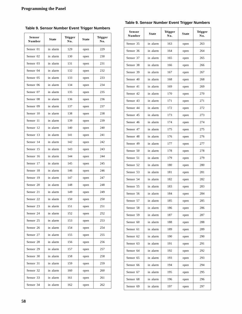
Programming the Panel
Table 9. Sensor Number Event Trigger Numbers
Sensor Number
StateTrigger
No.State
Trigger No.
Sensor 01 in alarm 129 open 229
Sensor 02 in alarm 130 open 230
Sensor 03 in alarm 131 open 231
Sensor 04 in alarm 132 open 232
Sensor 05 in alarm 133 open 233
Sensor 06 in alarm 134 open 234
Sensor 07 in alarm 135 open 235
Sensor 08 in alarm 136 open 236
Sensor 09 in alarm 137 open 237
Sensor 10 in alarm 138 open 238
Sensor 11 in alarm 139 open 239
Sensor 12 in alarm 140 open 240
Sensor 13 in alarm 141 open 241
Sensor 14 in alarm 142 open 242
Sensor 15 in alarm 143 open 243
Sensor 16 in alarm 144 open 244
Sensor 17 in alarm 145 open 245
Sensor 18 in alarm 146 open 246
Sensor 19 in alarm 147 open 247
Sensor 20 in alarm 148 open 248
Sensor 21 in alarm 149 open 249
Sensor 22 in alarm 150 open 250
Sensor 23 in alarm 151 open 251
Sensor 24 in alarm 152 open 252
Sensor 25 in alarm 153 open 253
Sensor 26 in alarm 154 open 254
Sensor 27 in alarm 155 open 255
Sensor 28 in alarm 156 open 256
Sensor 29 in alarm 157 open 257
Sensor 30 in alarm 158 open 258
Sensor 31 in alarm 159 open 259
Sensor 32 in alarm 160 open 260
Sensor 33 in alarm 161 open 261
Sensor 34 in alarm 162 open 262
Sensor 35 in alarm 163 open 263
Sensor 36 in alarm 164 open 264
Sensor 37 in alarm 165 open 265
Sensor 38 in alarm 166 open 266
Sensor 39 in alarm 167 open 267
Sensor 40 in alarm 168 open 268
Sensor 41 in alarm 169 open 269
Sensor 42 in alarm 170 open 270
Sensor 43 in alarm 171 open 271
Sensor 44 in alarm 172 open 272
Sensor 45 in alarm 173 open 273
Sensor 46 in alarm 174 open 274
Sensor 47 in alarm 175 open 275
Sensor 48 in alarm 176 open 276
Sensor 49 in alarm 177 open 277
Sensor 50 in alarm 178 open 278
Sensor 51 in alarm 179 open 279
Sensor 52 in alarm 180 open 280
Sensor 53 in alarm 181 open 281
Sensor 54 in alarm 182 open 282
Sensor 55 in alarm 183 open 283
Sensor 56 in alarm 184 open 284
Sensor 57 in alarm 185 open 285
Sensor 58 in alarm 186 open 286
Sensor 59 in alarm 187 open 287
Sensor 60 in alarm 188 open 288
Sensor 61 in alarm 189 open 289
Sensor 62 in alarm 190 open 290
Sensor 63 in alarm 191 open 291
Sensor 64 in alarm 192 open 292
Sensor 65 in alarm 193 open 293
Sensor 66 in alarm 194 open 294
Sensor 67 in alarm 195 open 295
Sensor 68 in alarm 196 open 296
Sensor 69 in alarm 197 open 297
Table 9. Sensor Number Event Trigger Numbers
Sensor Number
StateTrigger
No.State
Trigger No.
58
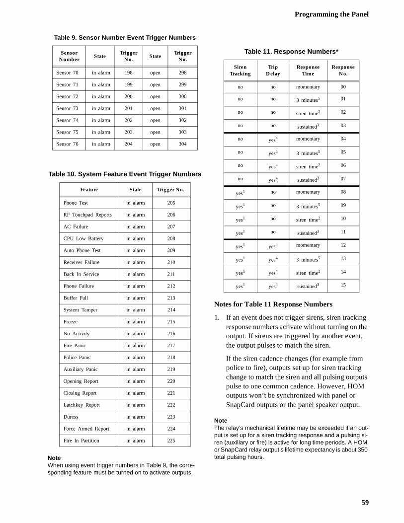
Programming the Panel
g he ,
ts
NoteWhen using event trigger numbers in Table 9, the corre-sponding feature must be turned on to activate outputs.
Notes for Table 11 Response Numbers
1. If an event does not trigger sirens, siren trackinresponse numbers activate without turning on toutput. If sirens are triggered by another eventthe output pulses to match the siren.
If the siren cadence changes (for example frompolice to fire), outputs set up for siren tracking change to match the siren and all pulsing outpupulse to one common cadence. However, HOMoutputs won’t be synchronized with panel or SnapCard outputs or the panel speaker output.
NoteThe relay’s mechanical lifetime may be exceeded if an out-put is set up for a siren tracking response and a pulsing si-ren (auxiliary or fire) is active for long time periods. A HOM or SnapCard relay output’s lifetime expectancy is about 350 total pulsing hours.
Sensor 70 in alarm 198 open 298
Sensor 71 in alarm 199 open 299
Sensor 72 in alarm 200 open 300
Sensor 73 in alarm 201 open 301
Sensor 74 in alarm 202 open 302
Sensor 75 in alarm 203 open 303
Sensor 76 in alarm 204 open 304
Table 10. System Feature Event Trigger Numbers
Feature State Trigger No.
Phone Test in alarm 205
RF Touchpad Reports in alarm 206
AC Failure in alarm 207
CPU Low Battery in alarm 208
Auto Phone Test in alarm 209
Receiver Failure in alarm 210
Back In Service in alarm 211
Phone Failure in alarm 212
Buffer Full in alarm 213
System Tamper in alarm 214
Freeze in alarm 215
No Activity in alarm 216
Fire Panic in alarm 217
Police Panic in alarm 218
Auxiliary Panic in alarm 219
Opening Report in alarm 220
Closing Report in alarm 221
Latchkey Report in alarm 222
Duress in alarm 223
Force Armed Report in alarm 224
Fire In Partition in alarm 225
Table 9. Sensor Number Event Trigger Numbers
Sensor Number
StateTrigger
No.State
Trigger No.
Table 11. Response Numbers*
Siren Tracking
Trip Delay
Response Time
Response No.
no no momentary 00
no no 3 minutes5 01
no no siren time2 02
no no sustained3 03
no yes4 momentary 04
no yes4 3 minutes5 05
no yes4 siren time2 06
no yes4 sustained3 07
yes1 no momentary 08
yes1 no 3 minutes5 09
yes1 no siren time2 10
yes1 no sustained3 11
yes1 yes4 momentary 12
yes1 yes4 3 minutes5 13
yes1 yes4 siren time2 14
yes1 yes4 sustained3 15
59
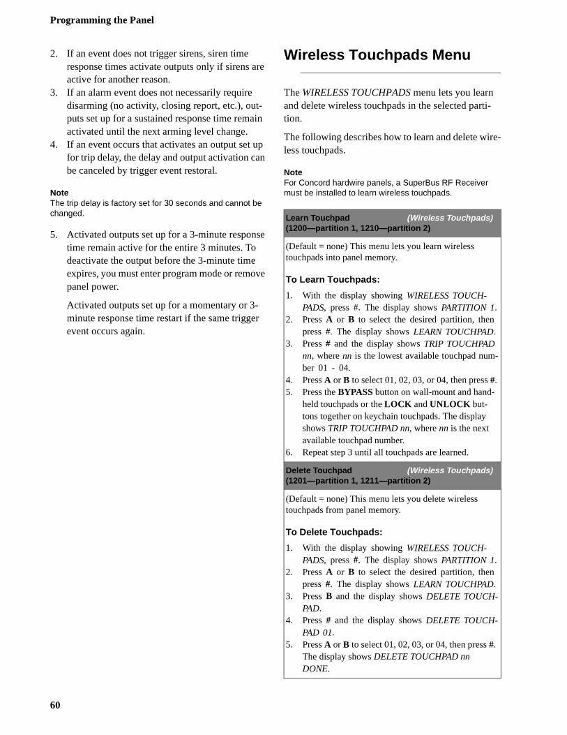
Programming the Panel
i-
e-
-
2. If an event does not trigger sirens, siren time response times activate outputs only if sirens are active for another reason.
3. If an alarm event does not necessarily require disarming (no activity, closing report, etc.), out-puts set up for a sustained response time remain activated until the next arming level change.
4. If an event occurs that activates an output set up for trip delay, the delay and output activation can be canceled by trigger event restoral.
NoteThe trip delay is factory set for 30 seconds and cannot be changed.
5. Activated outputs set up for a 3-minute response time remain active for the entire 3 minutes. To deactivate the output before the 3-minute time expires, you must enter program mode or remove panel power.
Activated outputs set up for a momentary or 3-minute response time restart if the same trigger event occurs again.
Wireless Touchpads Menu
The WIRELESS TOUCHPADS menu lets you learn and delete wireless touchpads in the selected parttion.
The following describes how to learn and delete wirless touchpads.
NoteFor Concord hardwire panels, a SuperBus RF Receiver must be installed to learn wireless touchpads.
Learn Touchpad (Wireless Touchpads)(1200—partition 1, 1210—partition 2)
(Default = none) This menu lets you learn wireless touchpads into panel memory.
To Learn Touchpads:
1. With the display showing WIRELESS TOUCH-PADS, press #. The display shows PARTITION 1.
2. Press A or B to select the desired partition, then press #. The display shows LEARN TOUCHPAD.
3. Press # and the display shows TRIP TOUCHPAD nn, where nn is the lowest available touchpad number 01 - 04.
4. Press A or B to select 01, 02, 03, or 04, then press #.5. Press the BYPASS button on wall-mount and hand-
held touchpads or the LOCK and UNLOCK but-tons together on keychain touchpads. The display shows TRIP TOUCHPAD nn, where nn is the next available touchpad number.
6. Repeat step 3 until all touchpads are learned.
Delete Touchpad (Wireless Touchpads)(1201—partition 1, 1211—partition 2)
(Default = none) This menu lets you delete wireless touchpads from panel memory.
To Delete Touchpads:
1. With the display showing WIRELESS TOUCH-PADS, press #. The display shows PARTITION 1.
2. Press A or B to select the desired partition, then press #. The display shows LEARN TOUCHPAD.
3. Press B and the display shows DELETE TOUCH-PAD.
4. Press # and the display shows DELETE TOUCH-PAD 01.
5. Press A or B to select 01, 02, 03, or 04, then press #. The display shows DELETE TOUCHPAD nn DONE.
60
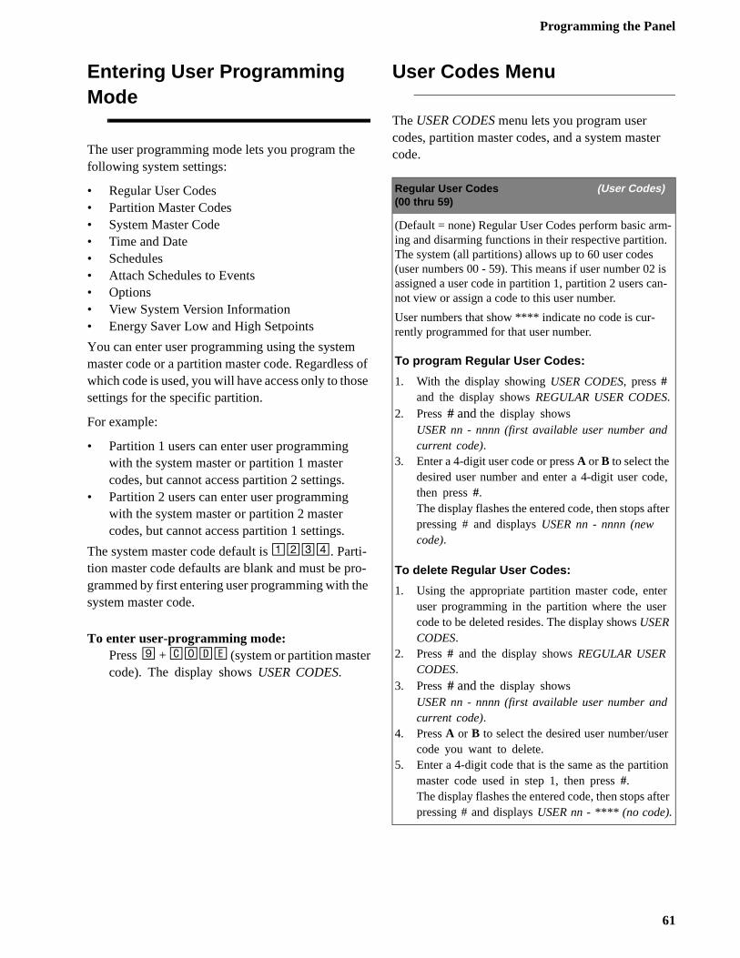
Programming the Panel
r
-.
is n-
e,
ter
r
r
n
ter
Entering User Programming Mode
The user programming mode lets you program the following system settings:
• Regular User Codes• Partition Master Codes• System Master Code• Time and Date• Schedules• Attach Schedules to Events• Options• View System Version Information• Energy Saver Low and High Setpoints
You can enter user programming using the system master code or a partition master code. Regardless of which code is used, you will have access only to those settings for the specific partition.
For example:
• Partition 1 users can enter user programming with the system master or partition 1 master codes, but cannot access partition 2 settings.
• Partition 2 users can enter user programming with the system master or partition 2 master codes, but cannot access partition 1 settings.
The system master code default is 1234. Parti-tion master code defaults are blank and must be pro-grammed by first entering user programming with the system master code.
To enter user-programming mode:Press 9 + CODE (system or partition mastercode). The display shows USER CODES.
User Codes Menu
The USER CODES menu lets you program user codes, partition master codes, and a system mastecode.
Regular User Codes (User Codes)(00 thru 59)
(Default = none) Regular User Codes perform basic arming and disarming functions in their respective partitionThe system (all partitions) allows up to 60 user codes (user numbers 00 - 59). This means if user number 02 assigned a user code in partition 1, partition 2 users canot view or assign a code to this user number.
User numbers that show **** indicate no code is cur-rently programmed for that user number.
To program Regular User Codes:
1. With the display showing USER CODES, press # and the display shows REGULAR USER CODES.
2. Press # and the display shows USER nn - nnnn (first available user number andcurrent code).
3. Enter a 4-digit user code or press A or B to select the desired user number and enter a 4-digit user codthen press #.The display flashes the entered code, then stops afpressing # and displays USER nn - nnnn (new code).
To delete Regular User Codes:
1. Using the appropriate partition master code, enteuser programming in the partition where the usercode to be deleted resides. The display shows USER CODES.
2. Press # and the display shows REGULAR USER CODES.
3. Press # and the display shows USER nn - nnnn (first available user number andcurrent code).
4. Press A or B to select the desired user number/usecode you want to delete.
5. Enter a 4-digit code that is the same as the partitiomaster code used in step 1, then press #.The display flashes the entered code, then stops afpressing # and displays USER nn - **** (no code).
61
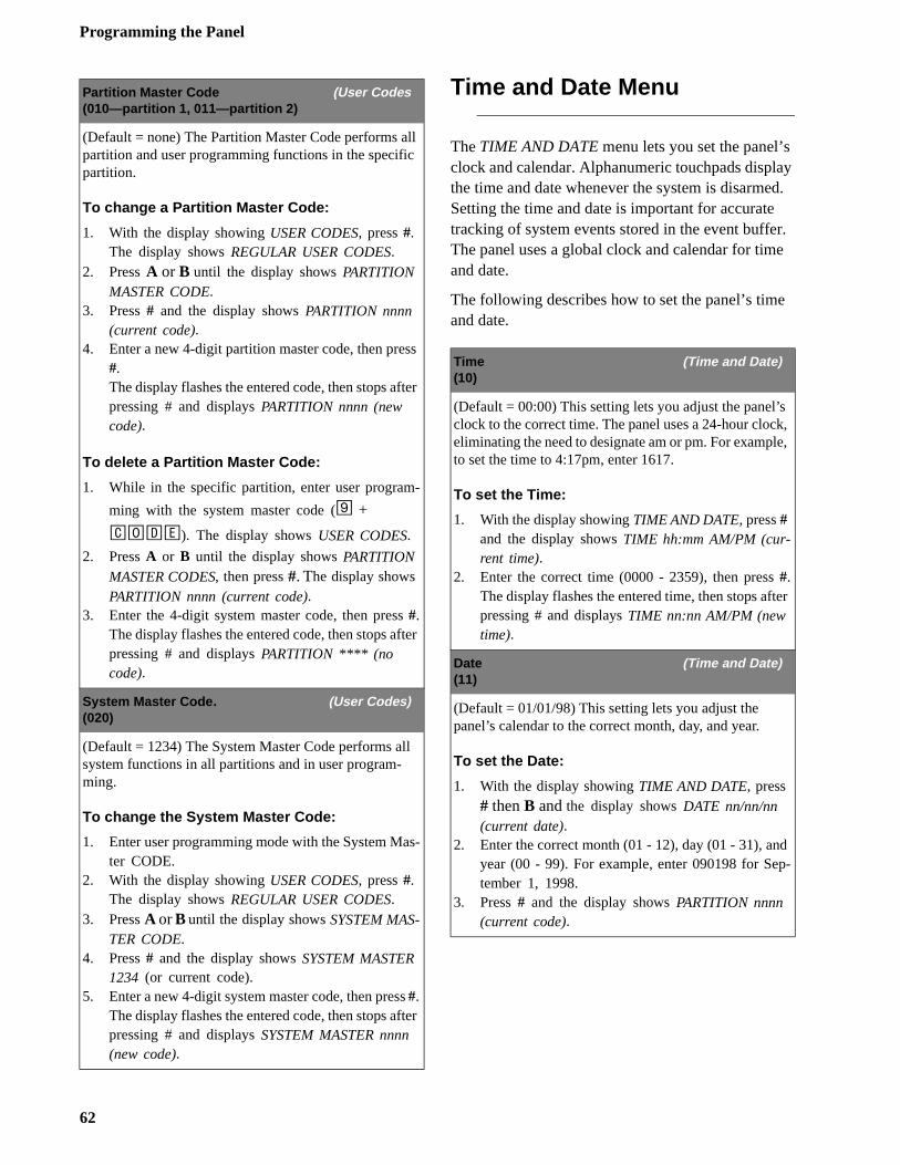
Programming the Panel
ay d. r. e
s k, e,
er
d p-
Time and Date Menu
The TIME AND DATE menu lets you set the panel’sclock and calendar. Alphanumeric touchpads displthe time and date whenever the system is disarmeSetting the time and date is important for accuratetracking of system events stored in the event buffeThe panel uses a global clock and calendar for timand date.
The following describes how to set the panel’s timeand date.
Partition Master Code (User Codes(010—partition 1, 011—partition 2)
(Default = none) The Partition Master Code performs all partition and user programming functions in the specific partition.
To change a Partition Master Code:
1. With the display showing USER CODES, press #. The display shows REGULAR USER CODES.
2. Press A or B until the display shows PARTITION MASTER CODE.
3. Press # and the display shows PARTITION nnnn (current code).
4. Enter a new 4-digit partition master code, then press #.The display flashes the entered code, then stops after pressing # and displays PARTITION nnnn (new code).
To delete a Partition Master Code:
1. While in the specific partition, enter user program-
ming with the system master code (9 +
CODE). The display shows USER CODES.
2. Press A or B until the display shows PARTITION MASTER CODES, then press #. The display shows PARTITION nnnn (current code).
3. Enter the 4-digit system master code, then press #.The display flashes the entered code, then stops after pressing # and displays PARTITION **** (no code).
System Master Code. (User Codes)(020)
(Default = 1234) The System Master Code performs all system functions in all partitions and in user program-ming.
To change the System Master Code:
1. Enter user programming mode with the System Mas-ter CODE.
2. With the display showing USER CODES, press #. The display shows REGULAR USER CODES.
3. Press A or B until the display shows SYSTEM MAS-TER CODE.
4. Press # and the display shows SYSTEM MASTER 1234 (or current code).
5. Enter a new 4-digit system master code, then press #.The display flashes the entered code, then stops after pressing # and displays SYSTEM MASTER nnnn (new code).
Time (Time and Date)(10)
(Default = 00:00) This setting lets you adjust the panel’clock to the correct time. The panel uses a 24-hour cloceliminating the need to designate am or pm. For examplto set the time to 4:17pm, enter 1617.
To set the Time:
1. With the display showing TIME AND DATE, press # and the display shows TIME hh:mm AM/PM (cur-rent time).
2. Enter the correct time (0000 - 2359), then press #.The display flashes the entered time, then stops aftpressing # and displays TIME nn:nn AM/PM (new time).
Date (Time and Date)(11)
(Default = 01/01/98) This setting lets you adjust the panel’s calendar to the correct month, day, and year.
To set the Date:
1. With the display showing TIME AND DATE, press # then B and the display shows DATE nn/nn/nn (current date).
2. Enter the correct month (01 - 12), day (01 - 31), anyear (00 - 99). For example, enter 090198 for Setember 1, 1998.
3. Press # and the display shows PARTITION nnnn (current code).
62
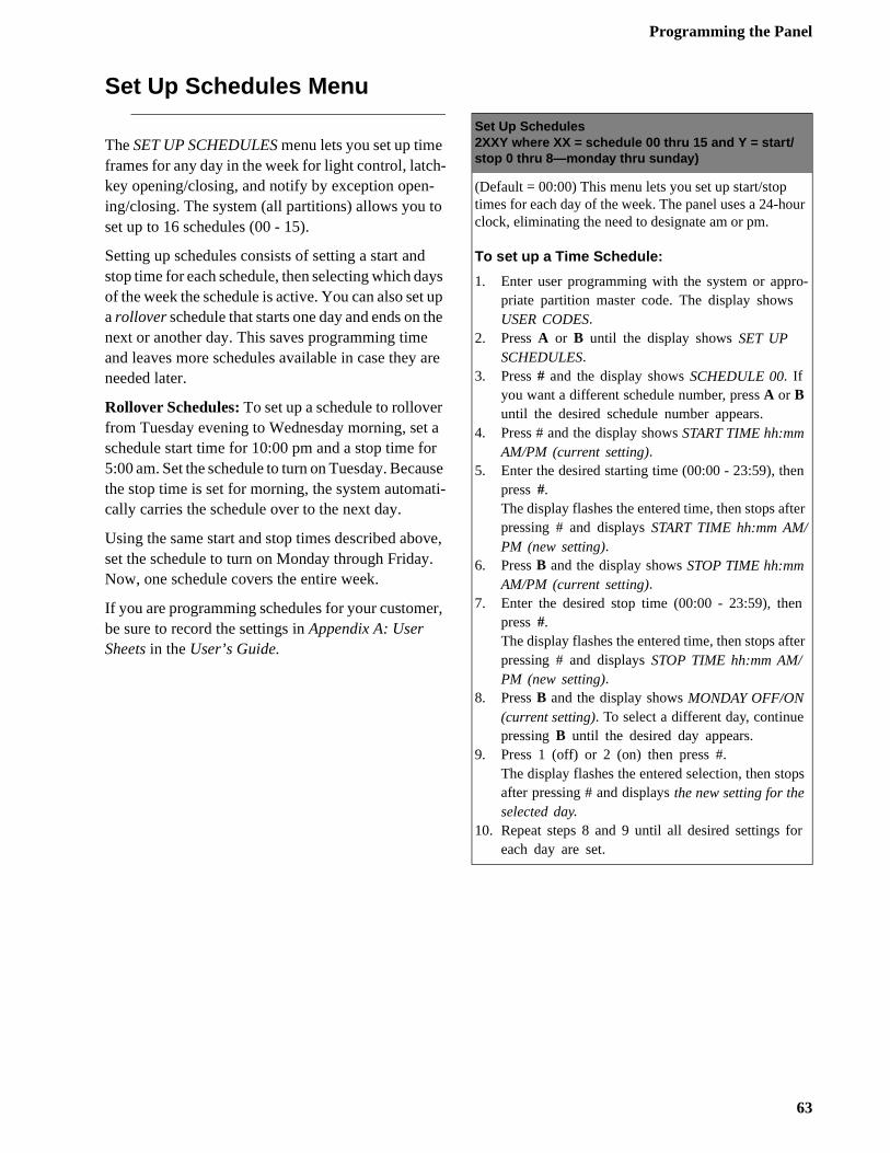
Programming the Panel
ur
o-
n
er
er
ps
r
Set Up Schedules Menu
The SET UP SCHEDULES menu lets you set up time frames for any day in the week for light control, latch-key opening/closing, and notify by exception open-ing/closing. The system (all partitions) allows you to set up to 16 schedules (00 - 15).
Setting up schedules consists of setting a start and stop time for each schedule, then selecting which days of the week the schedule is active. You can also set up a rollover schedule that starts one day and ends on the next or another day. This saves programming time and leaves more schedules available in case they are needed later.
Rollover Schedules: To set up a schedule to rollover from Tuesday evening to Wednesday morning, set a schedule start time for 10:00 pm and a stop time for 5:00 am. Set the schedule to turn on Tuesday. Because the stop time is set for morning, the system automati-cally carries the schedule over to the next day.
Using the same start and stop times described above, set the schedule to turn on Monday through Friday. Now, one schedule covers the entire week.
If you are programming schedules for your customer, be sure to record the settings in Appendix A: User Sheets in the User’s Guide.
Set Up Schedules2XXY where XX = schedule 00 thru 15 and Y = start/stop 0 thru 8—monday thru sunday)
(Default = 00:00) This menu lets you set up start/stop times for each day of the week. The panel uses a 24-hoclock, eliminating the need to designate am or pm.
To set up a Time Schedule:
1. Enter user programming with the system or apprpriate partition master code. The display shows USER CODES.
2. Press A or B until the display shows SET UP SCHEDULES.
3. Press # and the display shows SCHEDULE 00. If you want a different schedule number, press A or B until the desired schedule number appears.
4. Press # and the display shows START TIME hh:mm AM/PM (current setting).
5. Enter the desired starting time (00:00 - 23:59), thepress #.The display flashes the entered time, then stops aftpressing # and displays START TIME hh:mm AM/PM (new setting).
6. Press B and the display shows STOP TIME hh:mm AM/PM (current setting).
7. Enter the desired stop time (00:00 - 23:59), thenpress #.The display flashes the entered time, then stops aftpressing # and displays STOP TIME hh:mm AM/PM (new setting).
8. Press B and the display shows MONDAY OFF/ON (current setting). To select a different day, continue pressing B until the desired day appears.
9. Press 1 (off) or 2 (on) then press #.The display flashes the entered selection, then stoafter pressing # and displays the new setting for the selected day.
10. Repeat steps 8 and 9 until all desired settings foeach day are set.
63
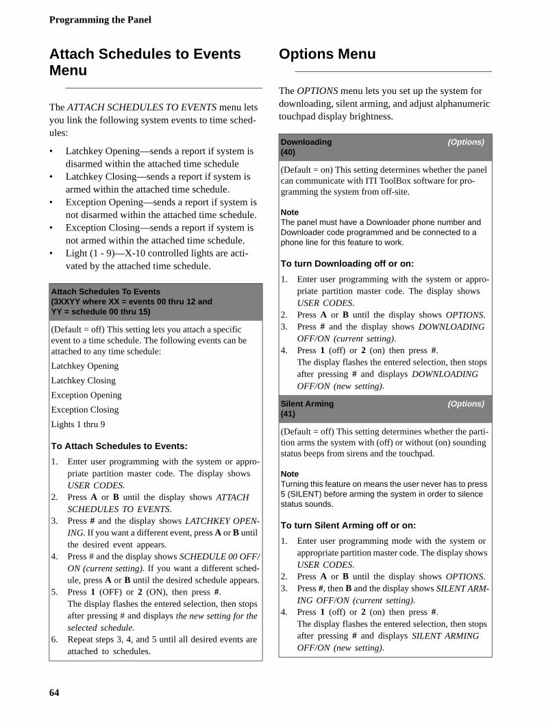
Programming the Panel
ic
el
o-
ps
i-
r s
ps
Attach Schedules to Events Menu
The ATTACH SCHEDULES TO EVENTS menu lets you link the following system events to time sched-ules:
• Latchkey Opening—sends a report if system is disarmed within the attached time schedule
• Latchkey Closing—sends a report if system is armed within the attached time schedule.
• Exception Opening—sends a report if system is not disarmed within the attached time schedule.
• Exception Closing—sends a report if system is not armed within the attached time schedule.
• Light (1 - 9)—X-10 controlled lights are acti-vated by the attached time schedule.
Options Menu
The OPTIONS menu lets you set up the system for downloading, silent arming, and adjust alphanumertouchpad display brightness.
Attach Schedules To Events(3XXYY where XX = events 00 thru 12 andYY = schedule 00 thru 15)
(Default = off) This setting lets you attach a specific event to a time schedule. The following events can be attached to any time schedule:
Latchkey Opening
Latchkey Closing
Exception Opening
Exception Closing
Lights 1 thru 9
To Attach Schedules to Events:
1. Enter user programming with the system or appro-priate partition master code. The display shows USER CODES.
2. Press A or B until the display shows ATTACH SCHEDULES TO EVENTS.
3. Press # and the display shows LATCHKEY OPEN-ING. If you want a different event, press A or B until the desired event appears.
4. Press # and the display shows SCHEDULE 00 OFF/ON (current setting). If you want a different sched-ule, press A or B until the desired schedule appears.
5. Press 1 (OFF) or 2 (ON), then press #.The display flashes the entered selection, then stops after pressing # and displays the new setting for the selected schedule.
6. Repeat steps 3, 4, and 5 until all desired events are attached to schedules.
Downloading (Options)(40)
(Default = on) This setting determines whether the pancan communicate with ITI ToolBox software for pro-gramming the system from off-site.
NoteThe panel must have a Downloader phone number and Downloader code programmed and be connected to a phone line for this feature to work.
To turn Downloading off or on:
1. Enter user programming with the system or apprpriate partition master code. The display shows USER CODES.
2. Press A or B until the display shows OPTIONS.3. Press # and the display shows DOWNLOADING
OFF/ON (current setting).4. Press 1 (off) or 2 (on) then press #.
The display flashes the entered selection, then stoafter pressing # and displays DOWNLOADING OFF/ON (new setting).
Silent Arming (Options)(41)
(Default = off) This setting determines whether the parttion arms the system with (off) or without (on) soundingstatus beeps from sirens and the touchpad.
NoteTurning this feature on means the user never has to press 5 (SILENT) before arming the system in order to silence status sounds.
To turn Silent Arming off or on:
1. Enter user programming mode with the system oappropriate partition master code. The display showUSER CODES.
2. Press A or B until the display shows OPTIONS.3. Press #, then B and the display shows SILENT ARM-
ING OFF/ON (current setting).4. Press 1 (off) or 2 (on) then press #.
The display flashes the entered selection, then stoafter pressing # and displays SILENT ARMING OFF/ON (new setting).
64
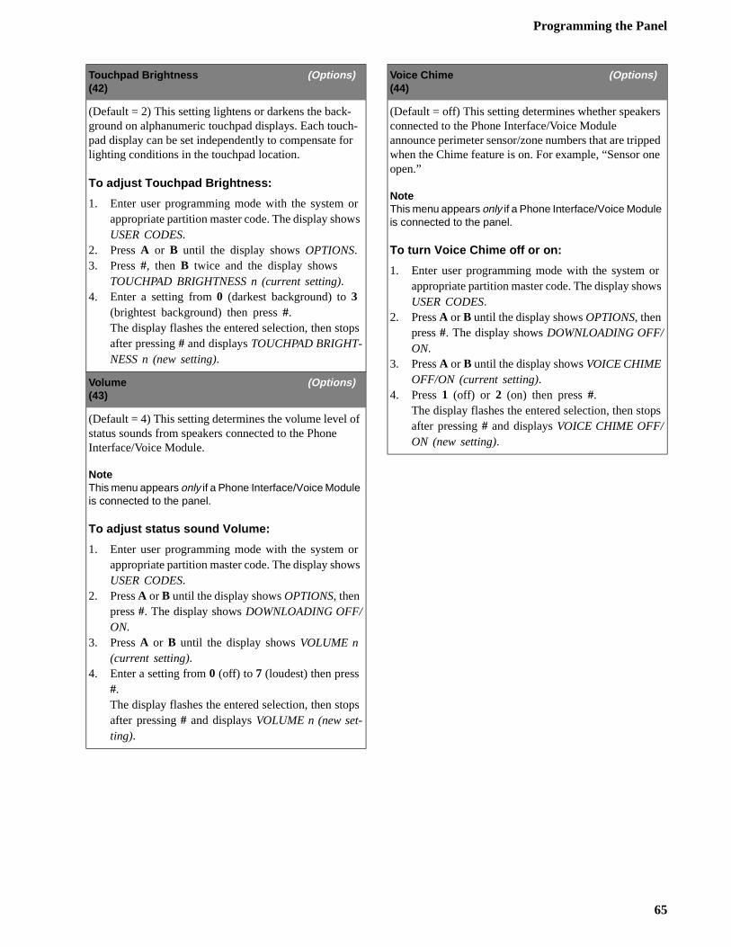
Programming the Panel
s
ed e
r s
ps
Touchpad Brightness (Options)(42)
(Default = 2) This setting lightens or darkens the back-ground on alphanumeric touchpad displays. Each touch-pad display can be set independently to compensate for lighting conditions in the touchpad location.
To adjust Touchpad Brightness:
1. Enter user programming mode with the system or appropriate partition master code. The display shows USER CODES.
2. Press A or B until the display shows OPTIONS.3. Press #, then B twice and the display shows
TOUCHPAD BRIGHTNESS n (current setting).4. Enter a setting from 0 (darkest background) to 3
(brightest background) then press #.The display flashes the entered selection, then stops after pressing # and displays TOUCHPAD BRIGHT-NESS n (new setting).
Volume (Options)(43)
(Default = 4) This setting determines the volume level of status sounds from speakers connected to the Phone Interface/Voice Module.
NoteThis menu appears only if a Phone Interface/Voice Module is connected to the panel.
To adjust status sound Volume:
1. Enter user programming mode with the system or appropriate partition master code. The display shows USER CODES.
2. Press A or B until the display shows OPTIONS, then press #. The display shows DOWNLOADING OFF/ON.
3. Press A or B until the display shows VOLUME n (current setting).
4. Enter a setting from 0 (off) to 7 (loudest) then press #.The display flashes the entered selection, then stops after pressing # and displays VOLUME n (new set-ting).
Voice Chime (Options)(44)
(Default = off) This setting determines whether speakerconnected to the Phone Interface/Voice Module announce perimeter sensor/zone numbers that are trippwhen the Chime feature is on. For example, “Sensor onopen.”
NoteThis menu appears only if a Phone Interface/Voice Module is connected to the panel.
To turn Voice Chime off or on:
1. Enter user programming mode with the system oappropriate partition master code. The display showUSER CODES.
2. Press A or B until the display shows OPTIONS, then press #. The display shows DOWNLOADING OFF/ON.
3. Press A or B until the display shows VOICE CHIME OFF/ON (current setting).
4. Press 1 (off) or 2 (on) then press #.The display flashes the entered selection, then stoafter pressing # and displays VOICE CHIME OFF/ON (new setting).
65
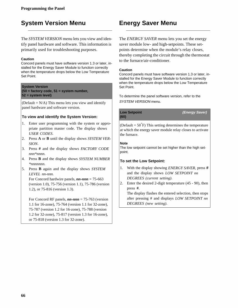
Programming the Panel
at
te
n
ps
System Version Menu
The SYSTEM VERSION menu lets you view and iden-tify panel hardware and software. This information is primarily used for troubleshooting purposes.
CautionConcord panels must have software version 1.3 or later, in-stalled for the Energy Saver Module to function correctly when the temperature drops below the Low Temperature Set Point.
Energy Saver Menu
The ENERGY SAVER menu lets you set the energy saver module low- and high-setpoints. These set-points determine when the module’s relay closes, thereby completing the circuit through the thermostto the furnace/air-conditioner.
CautionConcord panels must have software version 1.3 or later, in-stalled for the Energy Saver Module to function correctly when the temperature drops below the Low Temperature Set Point.
To determine the panel software version, refer to the
SYSTEM VERSION menu.
System Version(50 = factory code, 51 = system number,52 = system level)
(Default = N/A) This menu lets you view and identify panel hardware and software version.
To view and identify the System Version:
1. Enter user programming with the system or appro-priate partition master code. The display shows USER CODES.
2. Press A or B until the display shows SYSTEM VER-SION.
3. Press # and the display shows FACTORY CODE nnn*nnnn.
4. Press B and the display shows SYSTEM NUMBER *nnnnnnn.
5. Press B again and the display shows SYSTEM LEVEL nn-nnn.For Concord hardwire panels, nn-nnn = 75-663 (version 1.0), 75-756 (version 1.1), 75-786 (version 1.2), or 75-816 (version 1.3).
For Concord RF panels, nn-nnn = 75-763 (version 1.1 for 16-zone), 75-764 (version 1.1 for 32-zone), 75-787 (version 1.2 for 16-zone), 75-788 (version 1.2 for 32-zone), 75-817 (version 1.3 for 16-zone), or 75-818 (version 1.3 for 32-zone).
Low Setpoint (Energy Saver)(60)
(Default = 50°F) This setting determines the temperatureat which the energy saver module relay closes to activathe furnace.
NoteThe low setpoint cannot be set higher than the high set-point.
To set the Low Setpoint:
1. With the display showing ENERGY SAVER, press # and the display shows LOW SETPOINT nn DEGREES (current setting).
2. Enter the desired 2-digit temperature (45 - 90), thepress #.The display flashes the entered selection, then stoafter pressing # and displays LOW SETPOINT nn DEGREES (new setting).
66
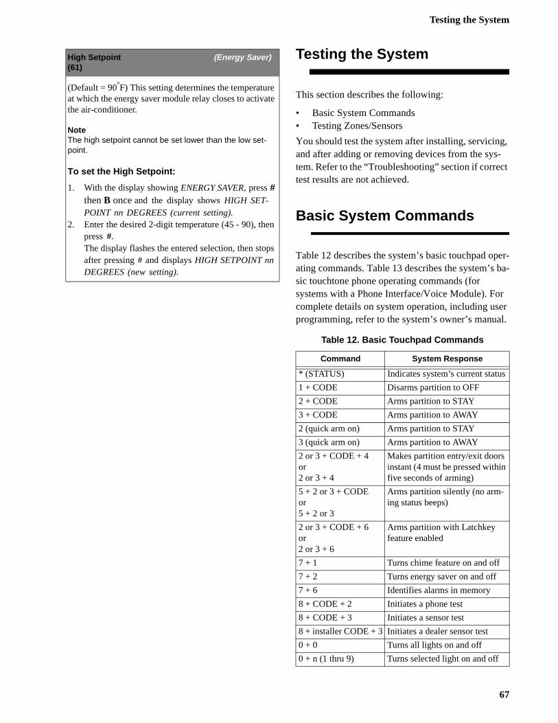
Testing the System
g, -t
er- ba-
r er l.
Testing the System
This section describes the following:
• Basic System Commands• Testing Zones/Sensors
You should test the system after installing, servicinand after adding or removing devices from the system. Refer to the “Troubleshooting” section if correctest results are not achieved.
Basic System Commands
Table 12 describes the system’s basic touchpad opating commands. Table 13 describes the system’ssic touchtone phone operating commands (for systems with a Phone Interface/Voice Module). Focomplete details on system operation, including usprogramming, refer to the system’s owner’s manua
High Setpoint (Energy Saver)(61)
(Default = 90°F) This setting determines the temperature at which the energy saver module relay closes to activate the air-conditioner.
NoteThe high setpoint cannot be set lower than the low set-point.
To set the High Setpoint:
1. With the display showing ENERGY SAVER, press # then B once and the display shows HIGH SET-POINT nn DEGREES (current setting).
2. Enter the desired 2-digit temperature (45 - 90), then press #.The display flashes the entered selection, then stops after pressing # and displays HIGH SETPOINT nn DEGREES (new setting).
Table 12. Basic Touchpad Commands
Command System Response
* (STATUS) Indicates system’s current status
1 + CODE Disarms partition to OFF
2 + CODE Arms partition to STAY
3 + CODE Arms partition to AWAY
2 (quick arm on) Arms partition to STAY
3 (quick arm on) Arms partition to AWAY
2 or 3 + CODE + 4or2 or 3 + 4
Makes partition entry/exit doors instant (4 must be pressed withinfive seconds of arming)
5 + 2 or 3 + CODEor5 + 2 or 3
Arms partition silently (no arm-ing status beeps)
2 or 3 + CODE + 6or2 or 3 + 6
Arms partition with Latchkey feature enabled
7 + 1 Turns chime feature on and off
7 + 2 Turns energy saver on and off
7 + 6 Identifies alarms in memory
8 + CODE + 2 Initiates a phone test
8 + CODE + 3 Initiates a sensor test
8 + installer CODE + 3 Initiates a dealer sensor test
0 + 0 Turns all lights on and off
0 + n (1 thru 9) Turns selected light on and off
67
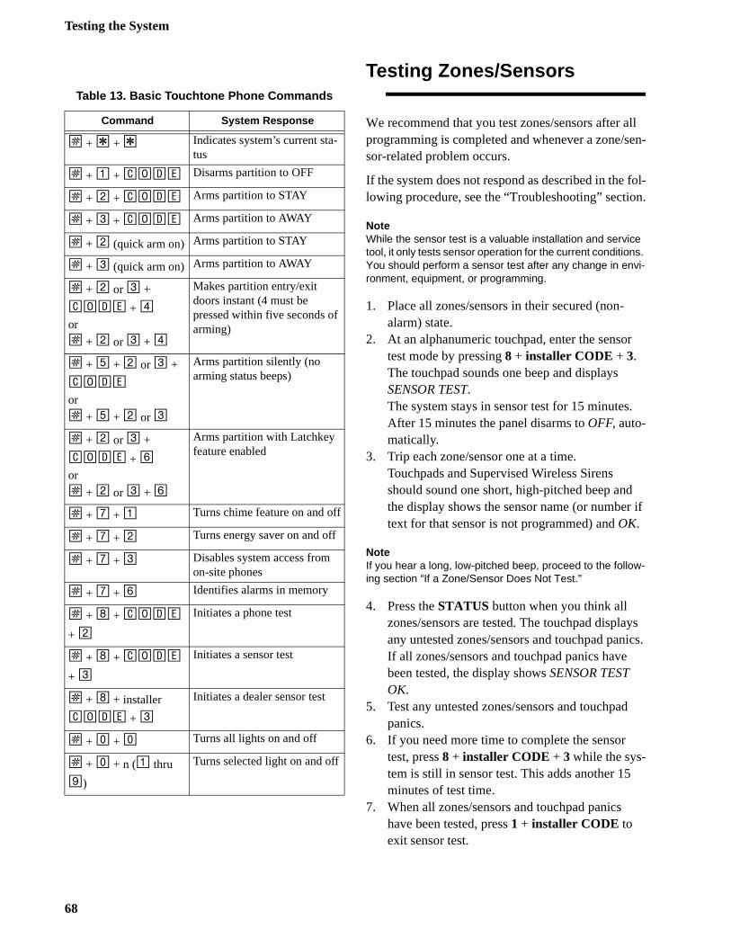
Testing the System
ll en-
fol-n.
r
.
if
ys ics.
Testing Zones/Sensors
We recommend that you test zones/sensors after aprogramming is completed and whenever a zone/ssor-related problem occurs.
If the system does not respond as described in thelowing procedure, see the “Troubleshooting” sectio
NoteWhile the sensor test is a valuable installation and service tool, it only tests sensor operation for the current conditions. You should perform a sensor test after any change in envi-ronment, equipment, or programming.
1. Place all zones/sensors in their secured (non-alarm) state.
2. At an alphanumeric touchpad, enter the sensotest mode by pressing 8 + installer CODE + 3. The touchpad sounds one beep and displays SENSOR TEST.The system stays in sensor test for 15 minutesAfter 15 minutes the panel disarms to OFF, auto-matically.
3. Trip each zone/sensor one at a time.Touchpads and Supervised Wireless Sirens should sound one short, high-pitched beep andthe display shows the sensor name (or numbertext for that sensor is not programmed) and OK.
NoteIf you hear a long, low-pitched beep, proceed to the follow-ing section “If a Zone/Sensor Does Not Test.”
4. Press the STATUS button when you think all zones/sensors are tested. The touchpad displaany untested zones/sensors and touchpad panIf all zones/sensors and touchpad panics havebeen tested, the display shows SENSOR TEST OK.
5. Test any untested zones/sensors and touchpadpanics.
6. If you need more time to complete the sensor test, press 8 + installer CODE + 3 while the sys-tem is still in sensor test. This adds another 15minutes of test time.
7. When all zones/sensors and touchpad panics have been tested, press 1 + installer CODE to exit sensor test.
Table 13. Basic Touchtone Phone Commands
Command System Response
ƒ + ‚ + ‚ Indicates system’s current sta-tus
ƒ + 1 + CODE Disarms partition to OFF
ƒ + 2 + CODE Arms partition to STAY
ƒ + 3 + CODE Arms partition to AWAY
ƒ + 2 (quick arm on) Arms partition to STAY
ƒ + 3 (quick arm on) Arms partition to AWAY
ƒ + 2 or 3 +
CODE + 4or
ƒ + 2 or 3 + 4
Makes partition entry/exit doors instant (4 must be pressed within five seconds of arming)
ƒ + 5 + 2 or 3 +
CODE
or
ƒ + 5 + 2 or 3
Arms partition silently (no arming status beeps)
ƒ + 2 or 3 +
CODE + 6or
ƒ + 2 or 3 + 6
Arms partition with Latchkey feature enabled
ƒ + 7 + 1 Turns chime feature on and off
ƒ + 7 + 2 Turns energy saver on and off
ƒ + 7 + 3 Disables system access from on-site phones
ƒ + 7 + 6 Identifies alarms in memory
ƒ + 8 + CODE
+ 2
Initiates a phone test
ƒ + 8 + CODE
+ 3
Initiates a sensor test
ƒ + 8 + installer
CODE + 3
Initiates a dealer sensor test
ƒ + 0 + 0 Turns all lights on and off
ƒ + 0 + n (1 thru
9)
Turns selected light on and off
68
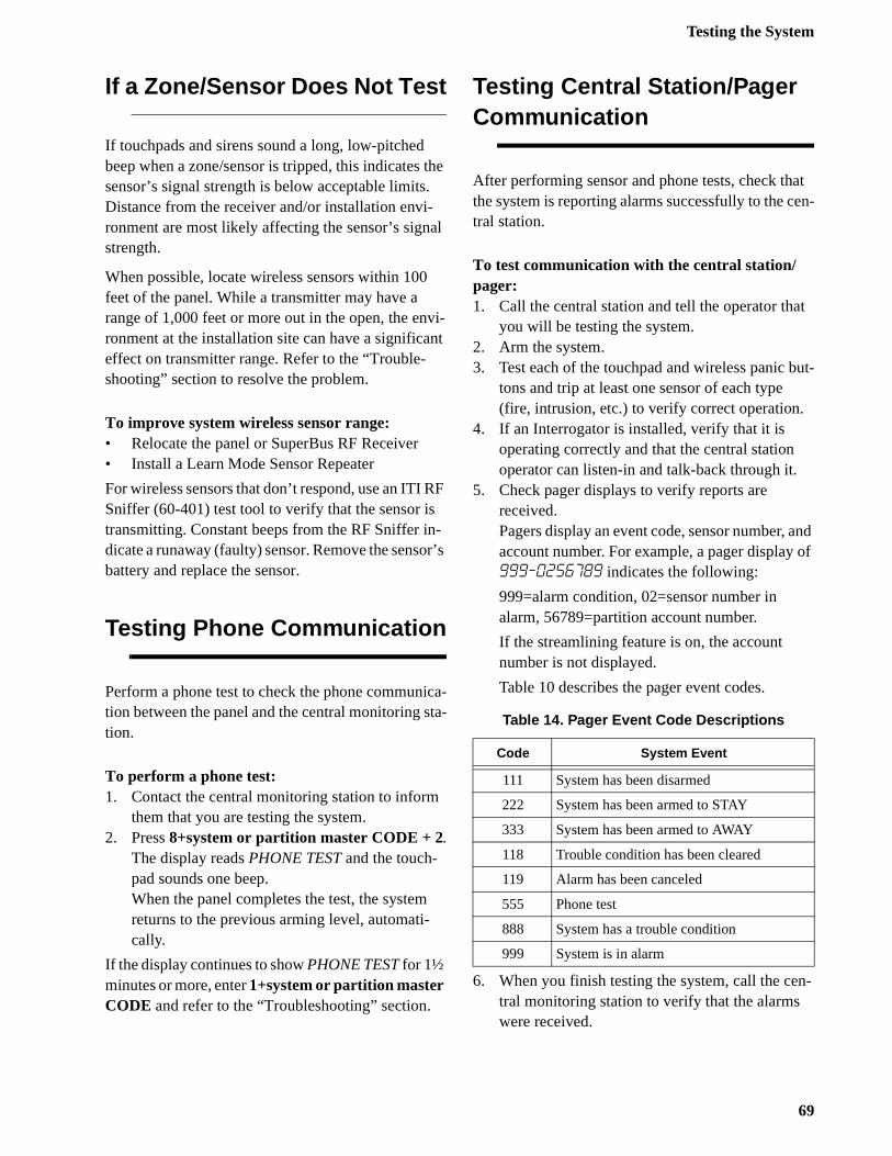
Testing the System
t en-
t
ut-
and of
n-
If a Zone/Sensor Does Not Test
If touchpads and sirens sound a long, low-pitched beep when a zone/sensor is tripped, this indicates the sensor’s signal strength is below acceptable limits. Distance from the receiver and/or installation envi-ronment are most likely affecting the sensor’s signal strength.
When possible, locate wireless sensors within 100 feet of the panel. While a transmitter may have a range of 1,000 feet or more out in the open, the envi-ronment at the installation site can have a significant effect on transmitter range. Refer to the “Trouble-shooting” section to resolve the problem.
To improve system wireless sensor range:• Relocate the panel or SuperBus RF Receiver• Install a Learn Mode Sensor Repeater
For wireless sensors that don’t respond, use an ITI RF Sniffer (60-401) test tool to verify that the sensor is transmitting. Constant beeps from the RF Sniffer in-dicate a runaway (faulty) sensor. Remove the sensor’s battery and replace the sensor.
Testing Phone Communication
Perform a phone test to check the phone communica-tion between the panel and the central monitoring sta-tion.
To perform a phone test:1. Contact the central monitoring station to inform
them that you are testing the system.2. Press 8+system or partition master CODE + 2.
The display reads PHONE TEST and the touch-pad sounds one beep.When the panel completes the test, the system returns to the previous arming level, automati-cally.
If the display continues to show PHONE TEST for 1½ minutes or more, enter 1+system or partition master CODE and refer to the “Troubleshooting” section.
Testing Central Station/Pager Communication
After performing sensor and phone tests, check thathe system is reporting alarms successfully to the ctral station.
To test communication with the central station/pager:1. Call the central station and tell the operator tha
you will be testing the system.2. Arm the system.3. Test each of the touchpad and wireless panic b
tons and trip at least one sensor of each type (fire, intrusion, etc.) to verify correct operation.
4. If an Interrogator is installed, verify that it is operating correctly and that the central station operator can listen-in and talk-back through it.
5. Check pager displays to verify reports are received.Pagers display an event code, sensor number, account number. For example, a pager display 999-0256789 indicates the following:
999=alarm condition, 02=sensor number in alarm, 56789=partition account number.
If the streamlining feature is on, the account number is not displayed.
Table 10 describes the pager event codes.
6. When you finish testing the system, call the cetral monitoring station to verify that the alarms were received.
Table 14. Pager Event Code Descriptions
Code System Event
111 System has been disarmed
222 System has been armed to STAY
333 System has been armed to AWAY
118 Trouble condition has been cleared
119 Alarm has been canceled
555 Phone test
888 System has a trouble condition
999 System is in alarm
69

Testing the System
e
Testing Outputs
All outputs (onboard, SnapCard, and HOM) should be tested to verify configuration programming.
CautionBe sure to contact the central monitoring station before ac-tivating outputs that trigger from an alarm condition.
To test outputs:1. Verify that all wiring at the panel and output
devices is correct.2. Activate each programmed system triggering
event to verify correct output response.
Testing Light Control
Test all lights plugged into X-10 Lamp Modules to verify house code and light number settings.
To test light control:1. Press 0 + 0 repeatedly to turn all lights on and off
together.2. Press 0 + 1 repeatedly to turn light 1 on and off.3. Repeat step 2 for remaining lights (0 + 2 for light
2, 0 + 3 for light 3, etc.).4. Arm the system to Away. All lights plugged into
modules set to Unit 1 should turn on and stay on for 5 minutes. All lights plugged into modules set to Unit 2 should blink three times to indicate the arming level. Remaining lights are unaf-fected.
5. Disarm the system. If Unit 1 lights were on for an entry or alarm, they will turn off in 5 minutes. Unit 2 lights should blink once to indicate the system is off. Remaining lights are unaffected.
6. All lights should turn on and remain on during fire and auxiliary/medical alarms and flash dur-ing a police or an intrusion alarm.
Testing the Energy Saver Module
Test the Energy Saver Module to verify it overridesthe thermostat.
CautionConcord panels must have software version 1.3 or later, in-stalled for the Energy Saver Module to function correctly when the temperature drops below the Low Temperature Set Point.
To determine the panel software version, refer to the
SYSTEM VERSION menu in User Programming, in the sec-
tion “Programming the Panel.”
NoteThe system must have high- and low-temperature limits set to test the Energy Saver Module.
To test the Energy Saver Module:1. Press STATUS + STATUS to display the sys-
tem status, ENERGY SAVER OFF, and the present TEMPERATURE nn°. The temperature displayed (and/or announced) should match thhouse thermostat. If the temperatures do not match, refer to the ACCESSORY MODULES—BUS DEVICES menu in the “Programming” sec-tion.
2. Press 7 + 2 to turn on the ESM. The display shows ENERGY SAVER ON and the ESM relay will click once.
3. Press 7 + 2 again to turn the ESM off. The dis-play shows ENERGY SAVER OFF.
NoteThere is a 5-minute delay after the Energy Saver Module re-turns control to the furnace/AC before it will override the fur-nace/AC again.
If the red ESM LED is not flashing continuously, remove panel AC and backup battery power. Verify that all wiring is correct and that all bus devices (including hardwire touch-pads) are set with different unit numbers.
Whenever the ESM unit number is changed, you must re-move and restore panel power, then enter the program mode so the panel and ESM communicate successfully.
70

Testing the System
Downloader Programming
The panel can be programmed remotely using Tool-Box. Use the information you recorded in Appendix A to inform the downloading operator of your instal-lation’s programming requirements.
ToolBox DownloaderProgramming
NoteA Downloader Phone Number must be programmed and user-programmable option Downloading must be set to on in order for remote downloader programming to work.
To initiate a ToolBox download session:1. Contact your download station and ask the oper-
ator to prepare to download to the panel.2. Make sure the system is disarmed.3. Press 8 + system or partition master CODE +
7 + 0 (any), 1 (down), or 2 (up).The display shows SYSTEM DOWNLOAD dur-ing the downloading process.
If the alphanumeric touchpad does not display SYS-TEM DOWNLOAD, call the downloader operator to verify the downloader phone number and that Tool-Box is set up properly. Refer to the “Troubleshoot-ing” section if the problem persists.
71
Troubleshooting
d into
Troubleshooting
This section describes what to do if you experience problems with system operation. Topics are divideseparate tables for easy reference.
• Table T1: Panel Power• Table T2: Access Codes• Table T3: Arming and Disarming• Table T4: Bypassing• Table T5: Wireless Sensor and Touchpad Batteries• Table T6: Central Station/Pager Reporting• Table T7: Alphanumeric Touchpads• Table T8: LED Touchpads• Table T9: Speakers• Table T10: Sirens• Table T11: Supervised Wireless Sirens• Table T12: Hardwire Zones• Table T13: Wireless Sensor Zones• Table T14: Wireless Touchpads• Table T15: Phones• Table T16: Light Control• Table T17: Energy Saver Module
73
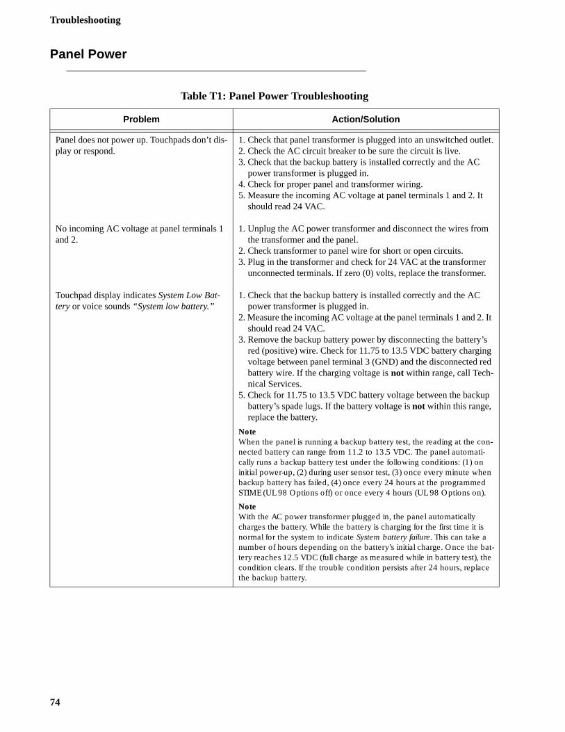
Troubleshooting
et.
.
It
s d
p
Panel Power
Table T1: Panel Power Troubleshooting
Problem Action/Solution
Panel does not power up. Touchpads don’t dis-play or respond.
No incoming AC voltage at panel terminals 1 and 2.
Touchpad display indicates System Low Bat-tery or voice sounds “System low battery.”
1. Check that panel transformer is plugged into an unswitched outl2. Check the AC circuit breaker to be sure the circuit is live.3. Check that the backup battery is installed correctly and the AC
power transformer is plugged in.4. Check for proper panel and transformer wiring.5. Measure the incoming AC voltage at panel terminals 1 and 2. It
should read 24 VAC.
1. Unplug the AC power transformer and disconnect the wires fromthe transformer and the panel.
2. Check transformer to panel wire for short or open circuits.3. Plug in the transformer and check for 24 VAC at the transformer
unconnected terminals. If zero (0) volts, replace the transformer
1. Check that the backup battery is installed correctly and the AC power transformer is plugged in.
2. Measure the incoming AC voltage at the panel terminals 1 and 2.should read 24 VAC.
3. Remove the backup battery power by disconnecting the battery’red (positive) wire. Check for 11.75 to 13.5 VDC battery chargingvoltage between panel terminal 3 (GND) and the disconnected rebattery wire. If the charging voltage is not within range, call Tech-nical Services.
5. Check for 11.75 to 13.5 VDC battery voltage between the backubattery’s spade lugs. If the battery voltage is not within this range, replace the battery.
NoteWhen the panel is running a backup battery test, the reading at the con-nected battery can range from 11.2 to 13.5 VDC. The panel automati-cally runs a backup battery test under the following conditions: (1) on initial power-up, (2) during user sensor test, (3) once every minute when backup battery has failed, (4) once every 24 hours at the programmed STIME (UL 98 Options off) or once every 4 hours (UL 98 Options on).
NoteWith the AC power transformer plugged in, the panel automatically charges the battery. While the battery is charging for the first time it is normal for the system to indicate System battery failure. This can take a number of hours depending on the battery’s initial charge. Once the bat-tery reaches 12.5 VDC (full charge as measured while in battery test), the condition clears. If the trouble condition persists after 24 hours, replace the backup battery.
74
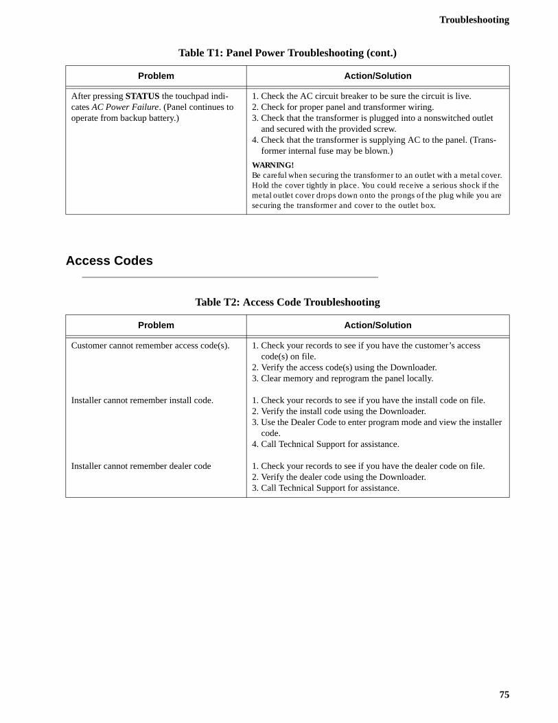
Troubleshooting
ler
Access Codes
After pressing STATUS the touchpad indi-cates AC Power Failure. (Panel continues to operate from backup battery.)
1. Check the AC circuit breaker to be sure the circuit is live.2. Check for proper panel and transformer wiring. 3. Check that the transformer is plugged into a nonswitched outlet
and secured with the provided screw.4. Check that the transformer is supplying AC to the panel. (Trans-
former internal fuse may be blown.)
WARNING!Be careful when securing the transformer to an outlet with a metal cover. Hold the cover tightly in place. You could receive a serious shock if the metal outlet cover drops down onto the prongs of the plug while you are securing the transformer and cover to the outlet box.
Table T2: Access Code Troubleshooting
Problem Action/Solution
Customer cannot remember access code(s).
Installer cannot remember install code.
Installer cannot remember dealer code
1. Check your records to see if you have the customer’s access code(s) on file.
2. Verify the access code(s) using the Downloader.3. Clear memory and reprogram the panel locally.
1. Check your records to see if you have the install code on file.2. Verify the install code using the Downloader.3. Use the Dealer Code to enter program mode and view the instal
code.4. Call Technical Support for assistance.
1. Check your records to see if you have the dealer code on file.2. Verify the dealer code using the Downloader.3. Call Technical Support for assistance.
Table T1: Panel Power Troubleshooting (cont.)
Problem Action/Solution
75
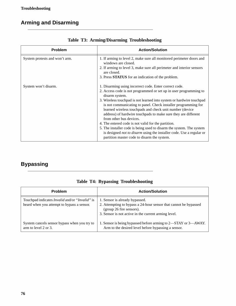
Troubleshooting
d
to
ad
m
.
Arming and Disarming
Bypassing
Table T3: Arming/Disarming Troubleshooting
Problem Action/Solution
System protests and won’t arm.
System won’t disarm.
1. If arming to level 2, make sure all monitored perimeter doors anwindows are closed.
2. If arming to level 3, make sure all perimeter and interior sensorsare closed.
3. Press STATUS for an indication of the problem.
1. Disarming using incorrect code. Enter correct code.2. Access code is not programmed or set up in user programming
disarm system.3. Wireless touchpad is not learned into system or hardwire touchp
is not communicating to panel. Check installer programming for learned wireless touchpads and check unit number (device address) of hardwire touchpads to make sure they are different from other bus devices.
4. The entered code is not valid for the partition.5. The installer code is being used to disarm the system. The syste
is designed not to disarm using the installer code. Use a regular orpartition master code to disarm the system.
Table T4: Bypassing Troubleshooting
Problem Action/Solution
Touchpad indicates Invalid and/or “Invalid” is heard when you attempt to bypass a sensor.
System cancels sensor bypass when you try to arm to level 2 or 3.
1. Sensor is already bypassed.2. Attempting to bypass a 24-hour sensor that cannot be bypassed
(group 26 fire sensors).3. Sensor is not active in the current arming level.
1. Sensor is being bypassed before arming to 2—STAY or 3—AWAYArm to the desired level before bypassing a sensor.
76
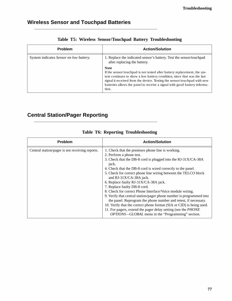
Troubleshooting
d
to y..
Wireless Sensor and Touchpad Batteries
Central Station/Pager Reporting
Table T5: Wireless Sensor/Touchpad Battery Troubleshooting
Problem Action/Solution
System indicates Sensor nn low battery. 1. Replace the indicated sensor’s battery. Test the sensor/touchpaafter replacing the battery.
NoteIf the sensor/touchpad is not tested after battery replacement, the sys-tem continues to show a low battery condition, since that was the last signal it received from the device. Testing the sensor/touchpad with new batteries allows the panel to receive a signal with good battery informa-tion.
Table T6: Reporting Troubleshooting
Problem Action/Solution
Central station/pager is not receiving reports. 1. Check that the premises phone line is working.2. Perform a phone test.3. Check that the DB-8 cord is plugged into the RJ-31X/CA-38A
jack.4. Check that the DB-8 cord is wired correctly to the panel.5. Check for correct phone line wiring between the TELCO block
and RJ-31X/CA-38A jack.6. Replace faulty RJ-31X/CA-38A jack.7. Replace faulty DB-8 cord.8. Check for correct Phone Interface/Voice module wiring.9. Verify that central station/pager phone number is programmed in
the panel. Reprogram the phone number and retest, if necessar10. Verify that the correct phone format (SIA or CID) is being used11. For pagers, extend the pager delay setting (see the PHONE
OPTIONS—GLOBAL menu in the “Programming” section.
77
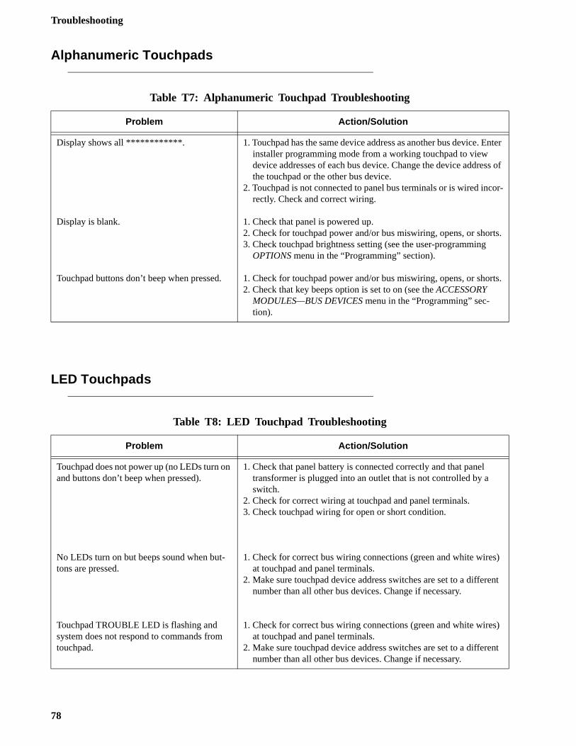
Troubleshooting
nter
s of
or-
ts.
ts.
)
nt
)
nt
Alphanumeric Touchpads
LED Touchpads
Table T7: Alphanumeric Touchpad Troubleshooting
Problem Action/Solution
Display shows all ************.
Display is blank.
Touchpad buttons don’t beep when pressed.
1. Touchpad has the same device address as another bus device. Einstaller programming mode from a working touchpad to view device addresses of each bus device. Change the device addresthe touchpad or the other bus device.
2. Touchpad is not connected to panel bus terminals or is wired increctly. Check and correct wiring.
1. Check that panel is powered up.2. Check for touchpad power and/or bus miswiring, opens, or shor3. Check touchpad brightness setting (see the user-programming
OPTIONS menu in the “Programming” section).
1. Check for touchpad power and/or bus miswiring, opens, or shor2. Check that key beeps option is set to on (see the ACCESSORY
MODULES—BUS DEVICES menu in the “Programming” sec-tion).
Table T8: LED Touchpad Troubleshooting
Problem Action/Solution
Touchpad does not power up (no LEDs turn on and buttons don’t beep when pressed).
No LEDs turn on but beeps sound when but-tons are pressed.
Touchpad TROUBLE LED is flashing and system does not respond to commands from touchpad.
1. Check that panel battery is connected correctly and that panel transformer is plugged into an outlet that is not controlled by a switch.
2. Check for correct wiring at touchpad and panel terminals.3. Check touchpad wiring for open or short condition.
1. Check for correct bus wiring connections (green and white wiresat touchpad and panel terminals.
2. Make sure touchpad device address switches are set to a differenumber than all other bus devices. Change if necessary.
1. Check for correct bus wiring connections (green and white wiresat touchpad and panel terminals.
2. Make sure touchpad device address switches are set to a differenumber than all other bus devices. Change if necessary.
78
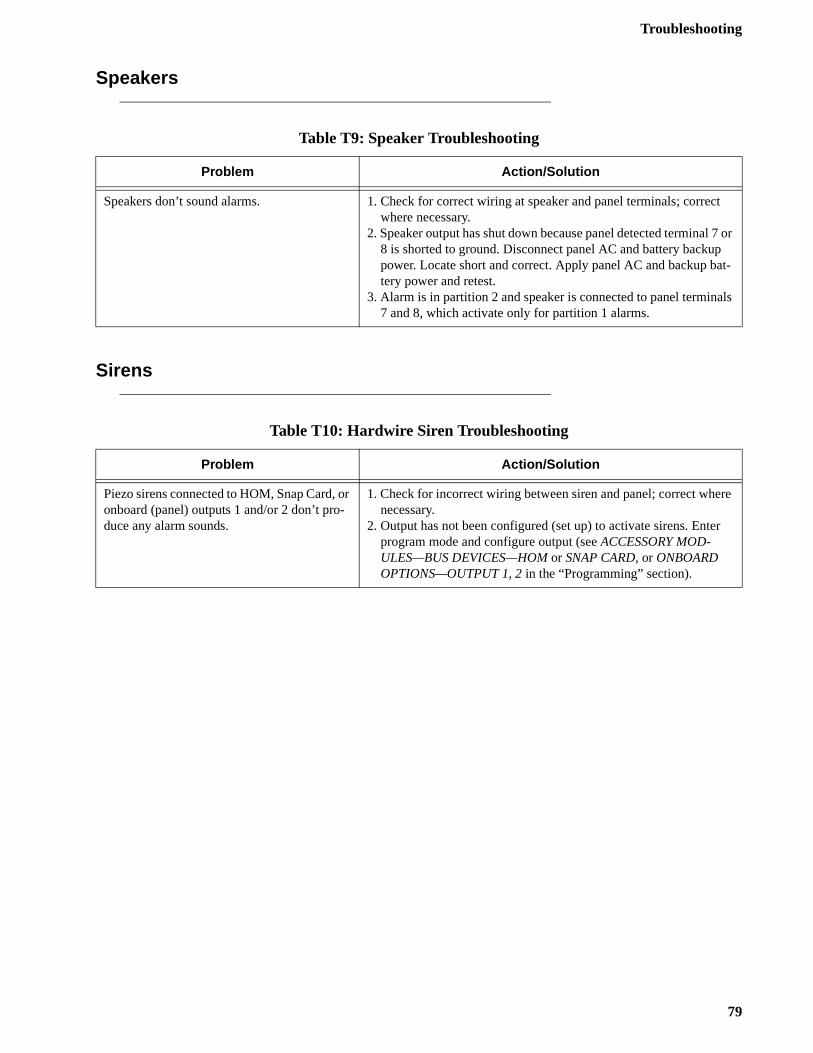
Troubleshooting
ect
7 or t-
ls
re
r
Speakers
Sirens
Table T9: Speaker Troubleshooting
Problem Action/Solution
Speakers don’t sound alarms. 1. Check for correct wiring at speaker and panel terminals; corrwhere necessary.
2. Speaker output has shut down because panel detected terminal 8 is shorted to ground. Disconnect panel AC and battery backuppower. Locate short and correct. Apply panel AC and backup batery power and retest.
3. Alarm is in partition 2 and speaker is connected to panel termina7 and 8, which activate only for partition 1 alarms.
Table T10: Hardwire Siren Troubleshooting
Problem Action/Solution
Piezo sirens connected to HOM, Snap Card, or onboard (panel) outputs 1 and/or 2 don’t pro-duce any alarm sounds.
1. Check for incorrect wiring between siren and panel; correct whenecessary.
2. Output has not been configured (set up) to activate sirens. Enteprogram mode and configure output (see ACCESSORY MOD-ULES—BUS DEVICES—HOM or SNAP CARD, or ONBOARD OPTIONS—OUTPUT 1, 2 in the “Programming” section).
79
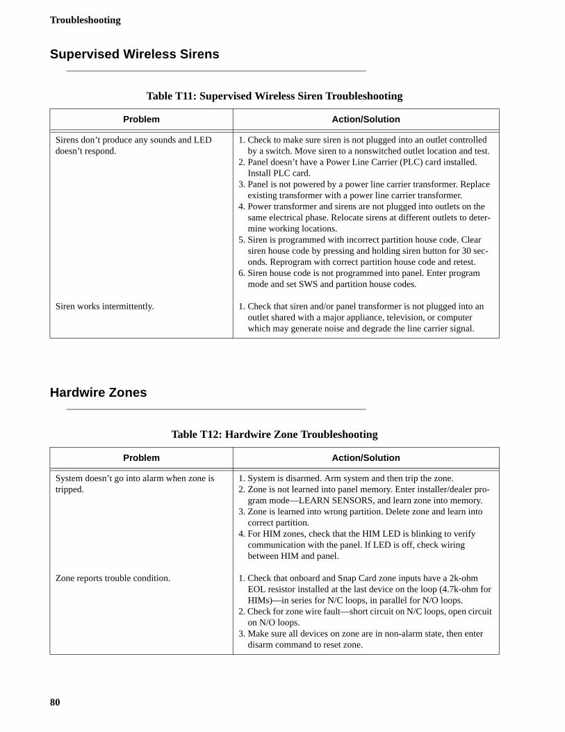
Troubleshooting
t.
e
er-
c-
-
r
t
r
Supervised Wireless Sirens
Hardwire Zones
Table T11: Supervised Wireless Siren Troubleshooting
Problem Action/Solution
Sirens don’t produce any sounds and LED doesn’t respond.
Siren works intermittently.
1. Check to make sure siren is not plugged into an outlet controlledby a switch. Move siren to a nonswitched outlet location and tes
2. Panel doesn’t have a Power Line Carrier (PLC) card installed. Install PLC card.
3. Panel is not powered by a power line carrier transformer. Replacexisting transformer with a power line carrier transformer.
4. Power transformer and sirens are not plugged into outlets on thesame electrical phase. Relocate sirens at different outlets to detmine working locations.
5. Siren is programmed with incorrect partition house code. Clear siren house code by pressing and holding siren button for 30 seonds. Reprogram with correct partition house code and retest.
6. Siren house code is not programmed into panel. Enter program mode and set SWS and partition house codes.
1. Check that siren and/or panel transformer is not plugged into anoutlet shared with a major appliance, television, or computer which may generate noise and degrade the line carrier signal.
Table T12: Hardwire Zone Troubleshooting
Problem Action/Solution
System doesn’t go into alarm when zone is tripped.
Zone reports trouble condition.
1. System is disarmed. Arm system and then trip the zone.2. Zone is not learned into panel memory. Enter installer/dealer pro
gram mode—LEARN SENSORS, and learn zone into memory.3. Zone is learned into wrong partition. Delete zone and learn into
correct partition.4. For HIM zones, check that the HIM LED is blinking to verify
communication with the panel. If LED is off, check wiring between HIM and panel.
1. Check that onboard and Snap Card zone inputs have a 2k-ohm EOL resistor installed at the last device on the loop (4.7k-ohm foHIMs)—in series for N/C loops, in parallel for N/O loops.
2. Check for zone wire fault—short circuit on N/C loops, open circuion N/O loops.
3. Make sure all devices on zone are in non-alarm state, then entedisarm command to reset zone.
80
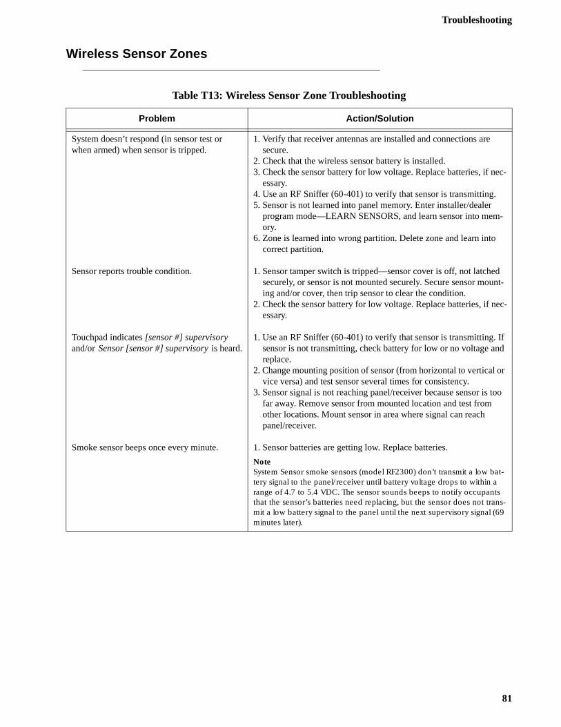
Troubleshooting
c-
-
nt-
ec-
f d
r
too
Wireless Sensor Zones
Table T13: Wireless Sensor Zone Troubleshooting
Problem Action/Solution
System doesn’t respond (in sensor test or when armed) when sensor is tripped.
Sensor reports trouble condition.
Touchpad indicates [sensor #] supervisory and/or Sensor [sensor #] supervisory is heard.
Smoke sensor beeps once every minute.
1. Verify that receiver antennas are installed and connections are secure.
2. Check that the wireless sensor battery is installed.3. Check the sensor battery for low voltage. Replace batteries, if ne
essary.4. Use an RF Sniffer (60-401) to verify that sensor is transmitting.5. Sensor is not learned into panel memory. Enter installer/dealer
program mode—LEARN SENSORS, and learn sensor into memory.
6. Zone is learned into wrong partition. Delete zone and learn into correct partition.
1. Sensor tamper switch is tripped—sensor cover is off, not latchedsecurely, or sensor is not mounted securely. Secure sensor mouing and/or cover, then trip sensor to clear the condition.
2. Check the sensor battery for low voltage. Replace batteries, if nessary.
1. Use an RF Sniffer (60-401) to verify that sensor is transmitting. Isensor is not transmitting, check battery for low or no voltage anreplace.
2. Change mounting position of sensor (from horizontal to vertical ovice versa) and test sensor several times for consistency.
3. Sensor signal is not reaching panel/receiver because sensor is far away. Remove sensor from mounted location and test from other locations. Mount sensor in area where signal can reach panel/receiver.
1. Sensor batteries are getting low. Replace batteries.
NoteSystem Sensor smoke sensors (model RF2300) don’t transmit a low bat-tery signal to the panel/receiver until battery voltage drops to within a range of 4.7 to 5.4 VDC. The sensor sounds beeps to notify occupants that the sensor’s batteries need replacing, but the sensor does not trans-mit a low battery signal to the panel until the next supervisory signal (69 minutes later).
81
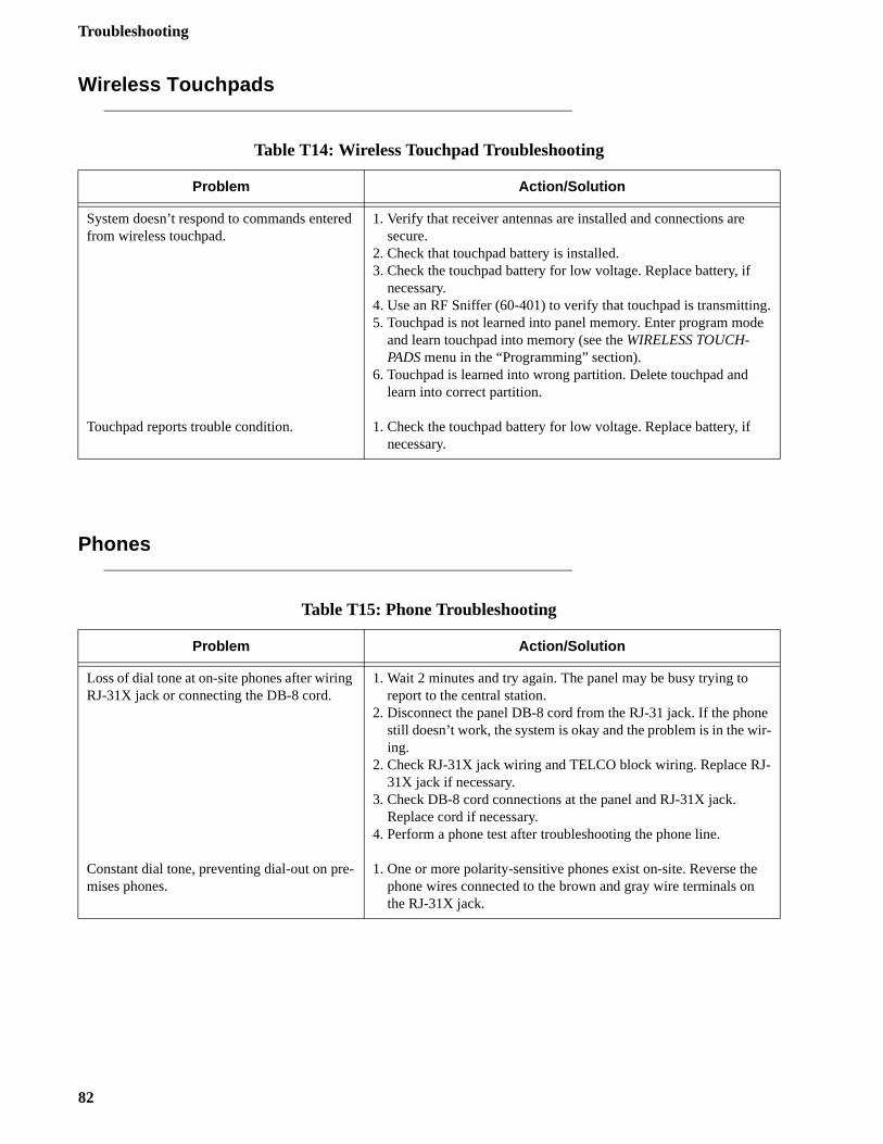
Troubleshooting
.e
e r-
-
Wireless Touchpads
Phones
Table T14: Wireless Touchpad Troubleshooting
Problem Action/Solution
System doesn’t respond to commands entered from wireless touchpad.
Touchpad reports trouble condition.
1. Verify that receiver antennas are installed and connections are secure.
2. Check that touchpad battery is installed.3. Check the touchpad battery for low voltage. Replace battery, if
necessary.4. Use an RF Sniffer (60-401) to verify that touchpad is transmitting5. Touchpad is not learned into panel memory. Enter program mod
and learn touchpad into memory (see the WIRELESS TOUCH-PADS menu in the “Programming” section).
6. Touchpad is learned into wrong partition. Delete touchpad and learn into correct partition.
1. Check the touchpad battery for low voltage. Replace battery, if necessary.
Table T15: Phone Troubleshooting
Problem Action/Solution
Loss of dial tone at on-site phones after wiring RJ-31X jack or connecting the DB-8 cord.
Constant dial tone, preventing dial-out on pre-mises phones.
1. Wait 2 minutes and try again. The panel may be busy trying to report to the central station.2. Disconnect the panel DB-8 cord from the RJ-31 jack. If the phon
still doesn’t work, the system is okay and the problem is in the wiing.
2. Check RJ-31X jack wiring and TELCO block wiring. Replace RJ31X jack if necessary.
3. Check DB-8 cord connections at the panel and RJ-31X jack. Replace cord if necessary.
4. Perform a phone test after troubleshooting the phone line.
1. One or more polarity-sensitive phones exist on-site. Reverse thephone wires connected to the brown and gray wire terminals on the RJ-31X jack.
82
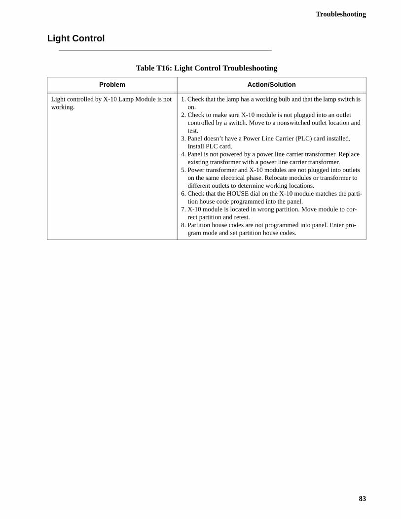
Troubleshooting
is
d
e
ts to
rti-
-
Light Control
Table T16: Light Control Troubleshooting
Problem Action/Solution
Light controlled by X-10 Lamp Module is not working.
1. Check that the lamp has a working bulb and that the lamp switchon.
2. Check to make sure X-10 module is not plugged into an outlet controlled by a switch. Move to a nonswitched outlet location antest.
3. Panel doesn’t have a Power Line Carrier (PLC) card installed. Install PLC card.
4. Panel is not powered by a power line carrier transformer. Replacexisting transformer with a power line carrier transformer.
5. Power transformer and X-10 modules are not plugged into outleon the same electrical phase. Relocate modules or transformer different outlets to determine working locations.
6. Check that the HOUSE dial on the X-10 module matches the pation house code programmed into the panel.
7. X-10 module is located in wrong partition. Move module to cor-rect partition and retest.
8. Partition house codes are not programmed into panel. Enter program mode and set partition house codes.
83
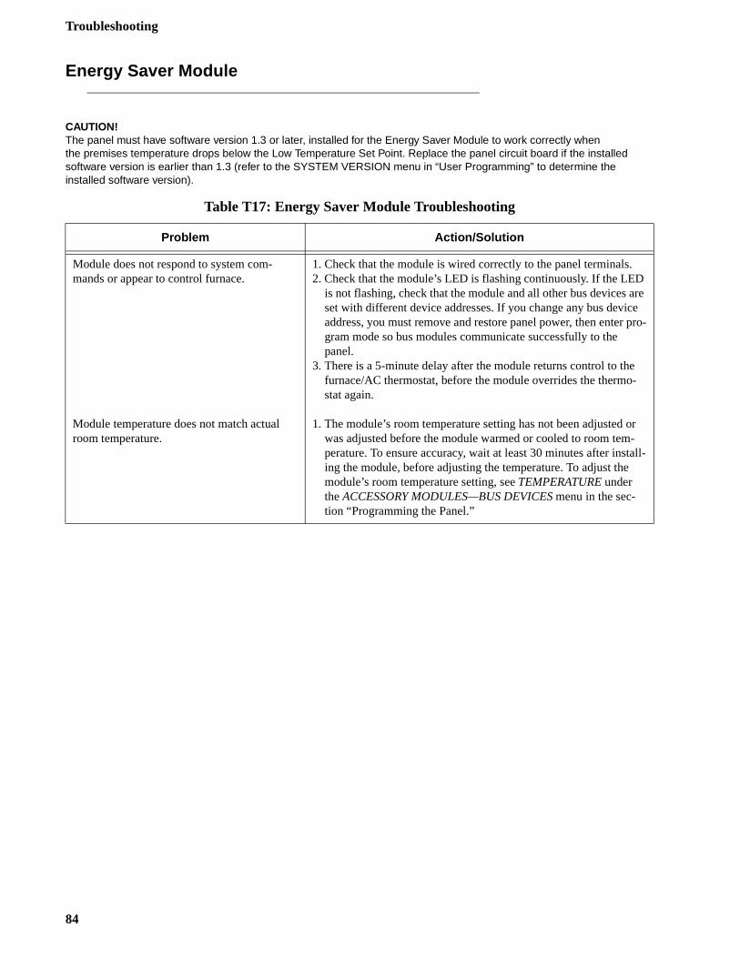
Troubleshooting
re e pro-
r
ll-
Energy Saver Module
CAUTION!The panel must have software version 1.3 or later, installed for the Energy Saver Module to work correctly when the premises temperature drops below the Low Temperature Set Point. Replace the panel circuit board if the installed software version is earlier than 1.3 (refer to the SYSTEM VERSION menu in “User Programming” to determine the installed software version).
Table T17: Energy Saver Module Troubleshooting
Problem Action/Solution
Module does not respond to system com-mands or appear to control furnace.
Module temperature does not match actual room temperature.
1. Check that the module is wired correctly to the panel terminals.2. Check that the module’s LED is flashing continuously. If the LED
is not flashing, check that the module and all other bus devices aset with different device addresses. If you change any bus devicaddress, you must remove and restore panel power, then enter gram mode so bus modules communicate successfully to the panel.
3. There is a 5-minute delay after the module returns control to thefurnace/AC thermostat, before the module overrides the thermo-stat again.
1. The module’s room temperature setting has not been adjusted owas adjusted before the module warmed or cooled to room tem-perature. To ensure accuracy, wait at least 30 minutes after instaing the module, before adjusting the temperature. To adjust the module’s room temperature setting, see TEMPERATURE under the ACCESSORY MODULES—BUS DEVICES menu in the sec-tion “Programming the Panel.”
84
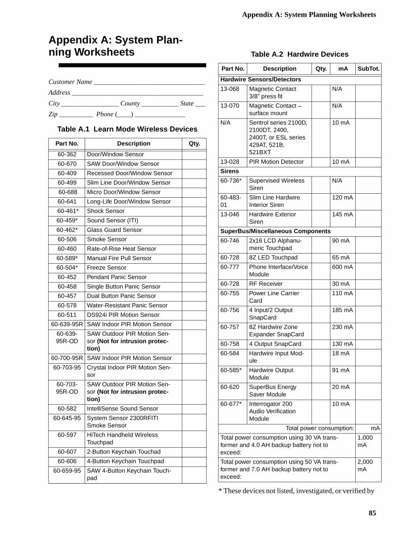
Appendix A: System Planning Worksheets
y
Appendix A: System Plan-ning Worksheets
Customer Name _________________________________
Address _______________________________________
City _________________ County ___________ State ___
Zip __________ Phone (____) _______________
* These devices not listed, investigated, or verified b
Table A.1 Learn Mode Wireless Devices
Part No. Description Qty.
60-362 Door/Window Sensor
60-670 SAW Door/Window Sensor
60-409 Recessed Door/Window Sensor
60-499 Slim Line Door/Window Sensor
60-688 Micro Door/Window Sensor
60-641 Long-Life Door/Window Sensor
60-461* Shock Sensor
60-459* Sound Sensor (ITI)
60-462* Glass Guard Sensor
60-506 Smoke Sensor
60-460 Rate-of-Rise Heat Sensor
60-589* Manual Fire Pull Sensor
60-504* Freeze Sensor
60-452 Pendant Panic Sensor
60-458 Single Button Panic Sensor
60-457 Dual Button Panic Sensor
60-578 Water-Resistant Panic Sensor
60-511 DS924i PIR Motion Sensor
60-639-95R SAW Indoor PIR Motion Sensor
60-639-95R-OD
SAW Outdoor PIR Motion Sen-sor (Not for intrusion protec-tion)
60-700-95R SAW Indoor PIR Motion Sensor
60-703-95 Crystal Indoor PIR Motion Sen-sor
60-703-95R-OD
SAW Outdoor PIR Motion Sen-sor (Not for intrusion protec-tion)
60-582 IntelliSense Sound Sensor
60-645-95 System Sensor 2300RFITI Smoke Sensor
60-597 HiTech Handheld Wireless Touchpad
60-607 2-Button Keychain Touchad
60-606 4-Button Keychain Touchpad
60-659-95 SAW 4-Button Keychain Touch-pad
Table A.2 Hardwire Devices
Part No. Description Qty. mA SubTot.
Hardwire Sensors/Detectors
13-068 Magnetic Contact3/8” press fit
N/A
13-070 Magnetic Contact – surface mount
N/A
N/A Sentrol series 2100D, 2100DT, 2400, 2400T, or ESL series 429AT, 521B, 521BXT
10 mA
13-028 PIR Motion Detector 10 mA
Sirens
60-736* Supervised Wireless Siren
N/A
60-483-01
Slim Line Hardwire Interior Siren
120 mA
13-046 Hardwire Exterior Siren
145 mA
SuperBus/Miscellaneous Components
60-746 2x16 LCD Alphanu-meric Touchpad
90 mA
60-728 8Z LED Touchpad 65 mA
60-777 Phone Interface/Voice Module
600 mA
60-728 RF Receiver 30 mA
60-755 Power Line Carrier Card
110 mA
60-756 4 Input/2 Output SnapCard
185 mA
60-757 8Z Hardwire Zone Expander SnapCard
230 mA
60-758 4 Output SnapCard 130 mA
60-584 Hardwire Input Mod-ule
18 mA
60-585* Hardwire Output Module
91 mA
60-620 SuperBus Energy Saver Module
20 mA
60-677* Interrogator 200 Audio Verification Module
10 mA
Total power consumption: mA
Total power consumption using 30 VA trans-former and 4.0 AH backup battery not to exceed:
1,000mA
Total power consumption using 50 VA trans-former and 7.0 AH backup battery not to exceed:
2,000 mA
85
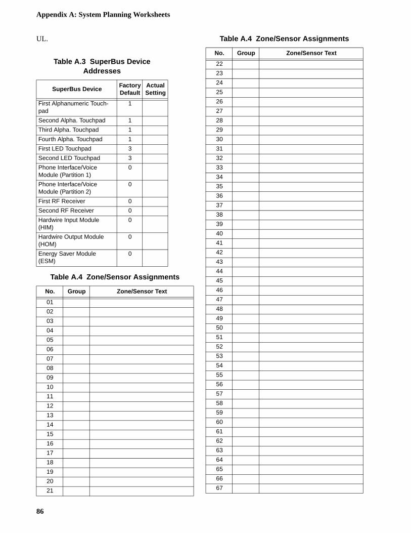
Appendix A: System Planning Worksheets
UL.
Table A.3 SuperBus Device Addresses
SuperBus DeviceFactoryDefault
ActualSetting
First Alphanumeric Touch-pad
1
Second Alpha. Touchpad 1
Third Alpha. Touchpad 1
Fourth Alpha. Touchpad 1
First LED Touchpad 3
Second LED Touchpad 3
Phone Interface/VoiceModule (Partition 1)
0
Phone Interface/VoiceModule (Partition 2)
0
First RF Receiver 0
Second RF Receiver 0
Hardwire Input Module (HIM)
0
Hardwire Output Module (HOM)
0
Energy Saver Module (ESM)
0
Table A.4 Zone/Sensor Assignments
No. Group Zone/Sensor Text
01
02
03
04
05
06
07
08
09
10
11
12
13
14
15
16
17
18
19
20
21
22
23
24
25
26
27
28
29
30
31
32
33
34
35
36
37
38
39
40
41
42
43
44
45
46
47
48
49
50
51
52
53
54
55
56
57
58
59
60
61
62
63
64
65
66
67
Table A.4 Zone/Sensor Assignments
No. Group Zone/Sensor Text
86
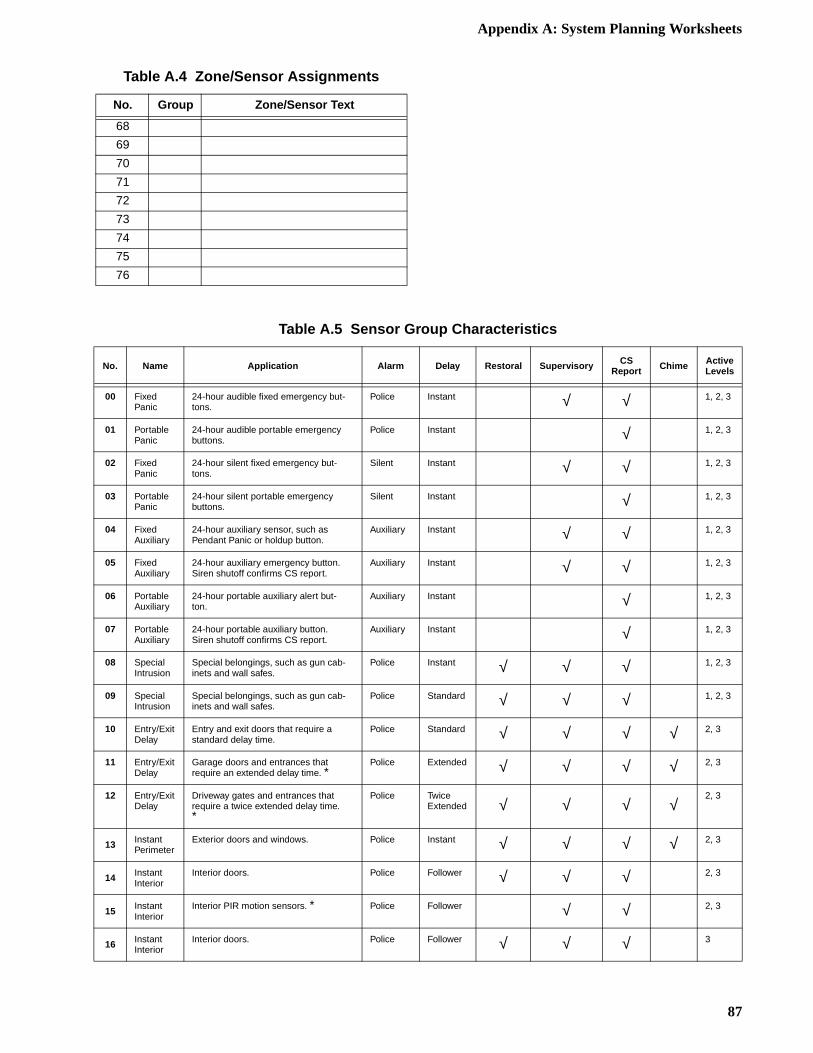
Appendix A: System Planning Worksheets
68
69
70
71
72
73
74
75
76
Table A.4 Zone/Sensor Assignments
No. Group Zone/Sensor Text
Table A.5 Sensor Group Characteristics
No. Name Application Alarm Delay Restoral Supervisory CS Report Chime Active
Levels
00 Fixed Panic
24-hour audible fixed emergency but-tons.
Police Instant √ √ 1, 2, 3
01 Portable Panic
24-hour audible portable emergency buttons.
Police Instant √ 1, 2, 3
02 Fixed Panic
24-hour silent fixed emergency but-tons.
Silent Instant √ √ 1, 2, 3
03 Portable Panic
24-hour silent portable emergency buttons.
Silent Instant √ 1, 2, 3
04 Fixed Auxiliary
24-hour auxiliary sensor, such as Pendant Panic or holdup button.
Auxiliary Instant √ √ 1, 2, 3
05 Fixed Auxiliary
24-hour auxiliary emergency button. Siren shutoff confirms CS report.
Auxiliary Instant √ √ 1, 2, 3
06 Portable Auxiliary
24-hour portable auxiliary alert but-ton.
Auxiliary Instant √ 1, 2, 3
07 Portable Auxiliary
24-hour portable auxiliary button. Siren shutoff confirms CS report.
Auxiliary Instant √ 1, 2, 3
08 Special Intrusion
Special belongings, such as gun cab-inets and wall safes.
Police Instant √ √ √ 1, 2, 3
09 Special Intrusion
Special belongings, such as gun cab-inets and wall safes.
Police Standard √ √ √ 1, 2, 3
10 Entry/Exit Delay
Entry and exit doors that require a standard delay time.
Police Standard √ √ √ √ 2, 3
11 Entry/Exit Delay
Garage doors and entrances that require an extended delay time. *
Police Extended √ √ √ √ 2, 3
12 Entry/Exit Delay
Driveway gates and entrances that require a twice extended delay time. *
Police TwiceExtended √ √ √ √
2, 3
13 Instant Perimeter
Exterior doors and windows. Police Instant √ √ √ √ 2, 3
14 Instant Interior
Interior doors. Police Follower √ √ √ 2, 3
15 Instant Interior
Interior PIR motion sensors. * Police Follower √ √ 2, 3
16 Instant Interior
Interior doors. Police Follower √ √ √ 3
87
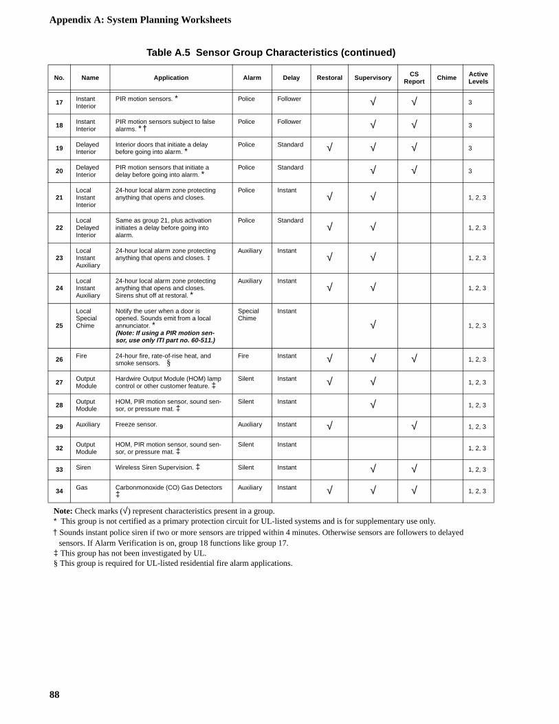
Appendix A: System Planning Worksheets
17 Instant Interior
PIR motion sensors. * Police Follower √ √ 3
18 Instant Interior
PIR motion sensors subject to false alarms. * †
Police Follower √ √ 3
19 Delayed Interior
Interior doors that initiate a delay before going into alarm. *
Police Standard √ √ √ 3
20 Delayed Interior
PIR motion sensors that initiate a delay before going into alarm. *
Police Standard √ √ 3
21Local Instant Interior
24-hour local alarm zone protecting anything that opens and closes.
Police Instant√ √ 1, 2, 3
22Local Delayed Interior
Same as group 21, plus activation initiates a delay before going into alarm.
Police Standard√ √ 1, 2, 3
23Local Instant Auxiliary
24-hour local alarm zone protecting anything that opens and closes. ‡
Auxiliary Instant√ √ 1, 2, 3
24Local Instant Auxiliary
24-hour local alarm zone protecting anything that opens and closes. Sirens shut off at restoral. *
Auxiliary Instant√ √ 1, 2, 3
25
Local Special Chime
Notify the user when a door is opened. Sounds emit from a local annunciator. *(Note: If using a PIR motion sen-sor, use only ITI part no. 60-511.)
Special Chime
Instant
√ 1, 2, 3
26 Fire 24-hour fire, rate-of-rise heat, and smoke sensors. §
Fire Instant √ √ √ 1, 2, 3
27 Output Module
Hardwire Output Module (HOM) lamp control or other customer feature. ‡
Silent Instant √ √ 1, 2, 3
28 Output Module
HOM, PIR motion sensor, sound sen-sor, or pressure mat. ‡
Silent Instant √ 1, 2, 3
29 Auxiliary Freeze sensor. Auxiliary Instant √ √ 1, 2, 3
32 Output Module
HOM, PIR motion sensor, sound sen-sor, or pressure mat. ‡
Silent Instant1, 2, 3
33 Siren Wireless Siren Supervision. ‡ Silent Instant √ √ 1, 2, 3
34 Gas Carbonmonoxide (CO) Gas Detectors ‡
Auxiliary Instant √ √ √ 1, 2, 3
Note: Check marks (√) represent characteristics present in a group.* This group is not certified as a primary protection circuit for UL-listed systems and is for supplementary use only.† Sounds instant police siren if two or more sensors are tripped within 4 minutes. Otherwise sensors are followers to delayed sensors. If Alarm Verification is on, group 18 functions like group 17.‡ This group has not been investigated by UL.§ This group is required for UL-listed residential fire alarm applications.
Table A.5 Sensor Group Characteristics (continued)
No. Name Application Alarm Delay Restoral Supervisory CS Report Chime Active
Levels
88
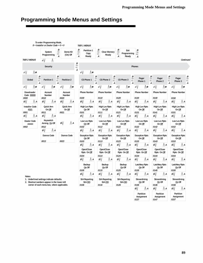
Programming Mode Menus and Settings
Programming Mode Menus and Settings
B A B AB A
B A B AB A
B A B AB A
B A B AB A
B A B AB A
B A B AB A
B A B AB A
# * # * # *
B A B AB A
B A B AB A
B A B AB A
B A B AB A
B A B AB A
B A B AB A
# * # * # * # # #
B A
B AB A
B A B AB A
A
B
A
B
A
B
A
B
A
B
A
B
#
Duress Code
Installer Code4321
Quick ArmOn Off
Dealer Codennnnn
Keyswitch Arming On Off
Global Partition 1 Partition 2
Downloader Code 00000
Account Number
Exception RptsOn Off
CS Phone 1 CS Phone 2 CS Phone 3
Phone Number
High Lev RptsOn Off
PagerPhone 1
Open/Close Rpts On Off
BackupOn Off
SIA ReportingSIA CID
Security
0001
# * # *
*
Low Lev RptsOn Off
PagerPhone 2
Latchkey RptsOn Off
StreamliningOn Off
PartitionAssignment
PartitionAssignment
PagerPhone 3
PartitionAssignment
* *
SystemProgramming
Demo Kit(On) Off
Partition 1Copy
Ready
Clear MemoryReady
ExitProgramming
Ready
A
B
A
B
A
B
A
B
A
B
A
B
A
B
To enter Programming Mode, 8 + Installer or Dealer Code + 0 + 0 TIER 1 MENUS
A
B
B A
Phones
TIER 2 MENUS
0000
0002 0012
0011
0010 0020
Account Number
0021
Quick ArmOn Off
0013 0023
Duress Code
0100
Phone Number
0110
0101
High Lev RptsOn Off
0111
Low Lev RptsOn Off
0102 0112
0103 0113
Exception RptsOn Off
Low Lev RptsOn Off
Exception RptsOn Off
0121
0122
0123
High Lev RptsOn Off
Phone Number
0120
Phone Number Phone Number
0130 0140
0131
High Lev RptsOn Off
0141
High Lev RptsOn Off
Low Lev RptsOn Off
0132
Low Lev RptsOn Off
0142
Exception RptsOn Off
0133
Exception RptsOn Off
0143
0114 0104 0124
Open/Close Rpts On Off
Open/Close Rpts On Off
BackupOn Off
0115 0105 0125
BackupOn Off
SIA ReportingSIA CID
0116 0106
SIA ReportingSIA CID
0126 0136
StreamliningOn Off
0146
StreamliningOn Off
0156
0157 0147 0137
Latchkey RptsOn Off
Latchkey RptsOn Off
0135 0145 0155
Open/Close Rpts On Off
Open/Close Rpts On Off
Open/Close Rpts On Off
0134 0144 0154
Low Lev RptsOn Off
0152
High Lev RptsOn Off
0151
0150
Phone Number
Exception RptsOn Off
0153
Continued
Notes1. Underlined settings indicate defaults.2. Shortcut numbers appear in the lower-left
corner of each menu box, where applicable.
89
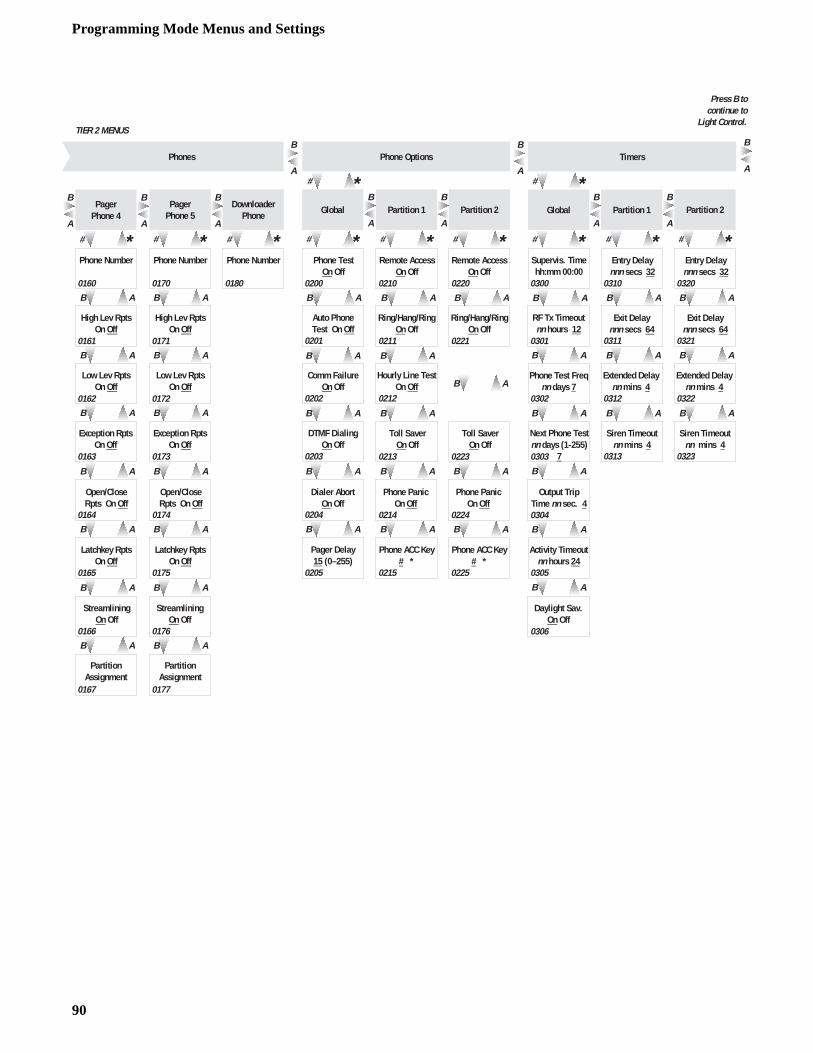
Programming Mode Menus and Settings
B AB AB A
B A B AB A
B A B AB A
B AB A
B A B AB A
# * # *
B A
B A
B A
# *
B A B AB A
B A B AB A
B AB A
# * # * # * # * # *
B A B A
B A B A
B A B A
B A B A
B A B A
B A B A
B A B A
A
B
A
B
A
B
A
B
A
B
A
B
# *
PagerPhone 5
Phone PanicOn Off
Comm FailureOn Off
Hourly Line TestOn Off
DTMF DialingOn Off
Toll SaverOn Off
Global Partition 1 Partition 2
Phone TestOn Off
Remote AccessOn Off
Auto PhoneTest On Off
Ring/Hang/RingOn Off
Phone Options
Dialer AbortOn Off
Phone ACC Key# *
Pager Delay15 (0–255)
DownloaderPhone
# *Pager
Phone 4
StreamliningOn Off
PartitionAssignment
Exception RptsOn Off
Latchkey RptsOn Off
PartitionAssignment
Phone Test Freqnn days 7
Extended Delay nn mins 4
Next Phone Testnn days (1-255)
7
Siren Timeoutnn mins 4
Global Partition 1 Partition 2
Supervis. Timehh:mm 00:00
Entry Delaynnn secs 32
RF Tx Timeoutnn hours 12
Exit Delaynnn secs 64
Timers
Output TripTime nn sec. 4
Activity Timeoutnn hours 24
Daylight Sav.On Off
# *
A
B
A
B
A
B
A
B
B A
Phones
Press B to continue to
Light Control.TIER 2 MENUS
0160
Phone Number
0170
Phone Number
High Lev RptsOn Off
0161
High Lev RptsOn Off
0171
Low Lev RptsOn Off
0162
Low Lev RptsOn Off
0172
0163
Exception RptsOn Off
0173
Open/Close Rpts On Off
0164
Open/Close Rpts On Off
0174
Latchkey RptsOn Off
0165 0175
0166 0176
StreamliningOn Off
0167 0177
Phone Number
0180 0200
0202
0201
0203
0204
0205
0210
Remote AccessOn Off
0220
0211
Ring/Hang/RingOn Off
0221
0212
0213
Toll SaverOn Off
0223
0214
Phone PanicOn Off
0224
0215
Phone ACC Key# *
0225
0300
0301
0302
0303
0304
0305
0306
0310
0311
Exit Delaynnn secs 64
0321
0320
Entry Delaynnn secs 32
Extended Delay nn mins 4
0312 0322
Siren Timeoutnn mins 4
0313 0323
90
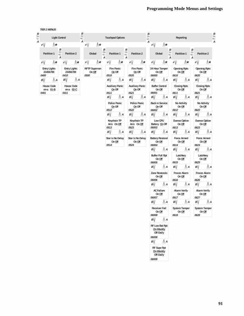
Programming Mode Menus and Settings
A
B
B A B A
B A B A
B A B A
B A B A
# *# * # *A
B
Keychain TP Arm On Off
Auxiliary PanicOn Off
Police PanicOn Off
Global Partition 1 Partition 2
RFTP SupervsnOn Off
Fire PanicOn Off
Touchpad Options
# *
Star is No DelayOn Off
A
B
A
B
B A B A
# *# *A
B
# *Partition 1 Partition 2
Entry Lights23456789
House Codenn-a 01-B
House Codenn-a 02-C
Light Control
B A B A
A
B
B A B A
B A B A
B A B A
B A B A
B AB A
B A B A
B A B A
B A
B A
RF Supv RptOn-WeeklyOff-Daily
RF Low Bat RptOn-WeeklyOff-Daily
Receiver FailOn Off
System TamperOn Off
Force ArmedOn Off
Low CPU Battery On Off
Duress OptionOn Off
Global Partition 1
24 Hour TamperOn Off
Opening RptsOn Off
Buffer ControlOn Off
Closing RptsOn Off
Zone RestoralsOn Off
# *
# *
Back in ServiceOn Off
No ActivityOn Off
Freeze AlarmOn Off
LatchkeyOn Off
# *
Battery RestoralOn Off
Buffer Full RptOn Off
AC FailureOn Off
Alarm VerifyOn Off
A
BTIER 2 MENUS
0400
Entry Lights23456789
0410
0401 0411
0500 0510
Fire PanicOn Off
0520
0511
Auxiliary PanicOn Off
0521
0512
Police PanicOn Off
0522
0513
Keychain TP Arm On Off
0523
0514
Star is No DelayOn Off
0524
06000 0610
06001
06002
06003
06004
06005
06006
06007
06008
06008
06009
0611
0612
0613
0614
0615
0616
0617
0618
A
B
B A
B A
B A
B A
Force ArmedOn Off
Duress OptionOn Off
Opening RptsOn Off
Closing RptsOn Off
No ActivityOn Off
# *
0620
0621
0622
0623
0624
B A
B A
B A
B A
System TamperOn Off
Freeze AlarmOn Off
LatchkeyOn Off
Alarm VerifyOn Off
0625
0626
0627
0628
Partition 2
A
BReporting
91
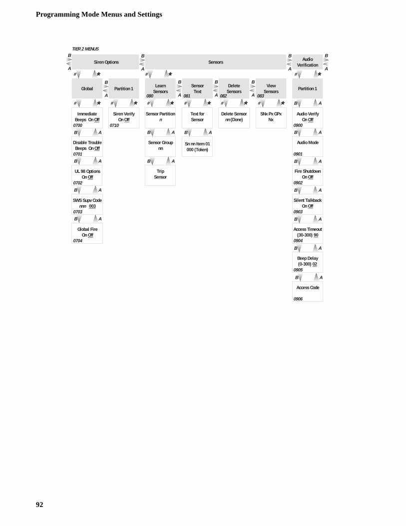
Programming Mode Menus and Settings
A
B
A
B
B A
B A
B A
SensorText
ViewSensors
SNx Px GPxNx
DeleteSensors
Delete Sensornn (Done)
Sensor Partitionn
Sensor Groupnn
TripSensor
Text forSensor
Sn nn Item 01000 (Token)
# * # * # *
Sensors
# *Learn
Sensors
# *A
B
A
B
B A
B A
B A
B A
B A
AudioVerification
B A
Access Timeout(30-300) 90
Fire ShutdownOn Off
Silent TalkbackOn Off
Partition 1
Audio VerifyOn Off
Audio Mode
Beep Delay(0-300) 02
Access Code
B A
A
B
A
B
B A
B A
B A
B A
Global
SWS Supv Codennn 003
Global FireOn Off
Immediate Beeps On Off
Disable TroubleBeeps On Off
UL 98 OptionsOn Off
Siren VerifyOn Off
# * # *
Siren Options
A
BPartition 1
0700
0701
0702
0703
0704
0710 0900
0901
0902
0903
0904
0905
0906
# *# *
TIER 2 MENUS
A
B
080 081 082 083
92
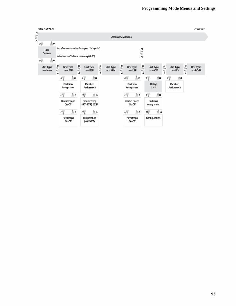
Programming Mode Menus and Settings
A
B
A
B
A
B
AB
A
B
A
B
B A
B A
# *
# *Bus
Devices
Unit Typenn - PIV
Accessory Modules
PartitionAssignment
AB
Unit Typenn - LTP
PartitionAssignment
Unit Typenn - HIM
B A
B A
Unit Typenn - ESM
PartitionAssignment
Freeze Temp(40º-90ºF) 42ºF
Unit Typenn - ATP
PartitionAssignment
Status BeepsOn Off
Key BeepsOn Off
Unit Typenn - None
Unit Typenn-RCVR
Maximum of 16 bus devices (00-15).
No shortcuts available beyond this point.
A
B
# * # * # * # *# *
# *
B A
PartitionAssignment
Configuration
Unit Typenn-HOM
Relays1 – 4
A
B
A
B
A
BTIER 2 MENUS
Temperature(40º-90ºF)
Status BeepsOn Off
Key BeepsOn Off
Continued
93
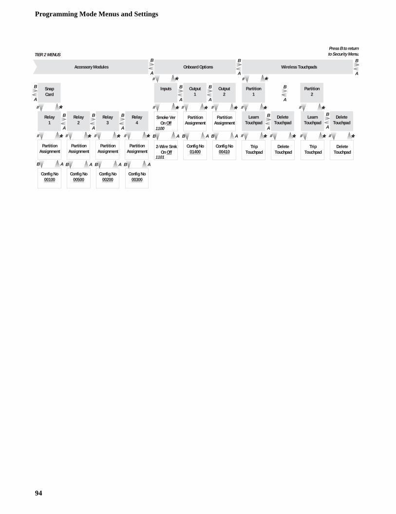
Programming Mode Menus and Settings
# *# *# *# *# * # * # * # *
B A B AB AB A
A
B
# *
Smoke VerOn Off
Onboard Options
2-Wire SmkOn Off
Press B to returnto Security Menu.
Accessory Modules
SnapCard
# *A
B
TIER 2 MENUS
1100
1101
Relay1
Config No00100
PartitionAssignment
Relay2
Config No00500
PartitionAssignment
Relay3
Config No00200
PartitionAssignment
Relay4
Config No00300
PartitionAssignment
A
B
A
B
A
B
A
B
# * # *
B AB A
Inputs Output1
Config No01400
PartitionAssignment
Output2
Config No00410
PartitionAssignment
A
B
A
B
# *
B A
# *
TripTouchpad
# *
Partition1
Partition2
LearnTouchpad
DeleteTouchpad
DeleteTouchpad
# *A
B
TripTouchpad
LearnTouchpad
DeleteTouchpad
DeleteTouchpad
A
B
A
B
A
BWireless Touchpads
94

Programming Mode Menus and Settings
95

Note 1
Clacepconare
Note 2
Anlatito pmupan
Note 3
Spwitspetwo
Note 4
OnOuuraset
Note 5
Zozoall
Note 6
Fotortorin
y-sensitive. Green and red wires may need to be
rification Modules are allowed. Wire multiple r and microphone wires in parallel. Use shielded
m to prevent cross-talk between the speaker and on Modules shall not be used in UL Listed in-
s in parallel. Status beeps do not sound from pi-uts. Slim Line Hardwire Interior Siren status vol- effect.
e set with a different device address before ap-e same device address setting will not work cor-ust one touchpad and one module, the default
odule installation instructions for thermostat wir-ing details.
zone (loop) inputs as shown for the panel, ex-tors. Install EOL resistors across all unused zone
ne (loop) wiring shown is an example that applies to all zones (except when ne 8 is configured for 2-wire smoke detectors). Install EOL resistors across unused zone (loop) inputs.
r UL Listed installations, wire multiple supervised hardwire smoke detec-s (10 maximum) only as shown. Maximum 10 uA current draw per detec-. Maximum 80 mA current draw in alarm. Maximum 100 mA current draw non-alarm state.
Note 12
Wire Hardwire Input Modulecept use 4.7k-ohm EOL resis(loop) inputs.
System Wiring Notes
ss II power transformer must be plugged into an unswitched AC power re-tacle. Do not short the transformer terminals together. The transformer tains an internal fuse that permanently disables the output if the terminals shorted.
alphanumeric touchpad is required for on-site programming. If the instal-on includes more than one touchpad, connect just one touchpad and use it rogram system settings. When connecting additional touchpads, each one st be set with a unique (different) device address. Refer to the touchpad or el installation instructions.
eaker terminals 7 and 8 activate only for alarms in partition 1. Use speakers h an 8-ohm or higher impedance. When connecting two or more 8-ohm akers, they must be wired in series as shown in the wiring diagram. Wiring or more 8-ohm speakers in parallel can permanently damage the panel.
board outputs 1 and 2 are open-collector type rated for 200 mA maximum. tput 1 defaults to configuration number 01400. Output 2 defaults to config-tion number 00410. Refer to panel installation instructions for all possible tings.
Note 7
Some telephones are polaritreversed.
Note 8
A maximum of two Audio Vespeakers in series, and powecable where shown in diagramicrophone. Audio Verificatistallations.
Note 9
Connect multiple piezo sirenezo sirens connected to outpume switch settings have no
Note 10
All SuperBus devices must bplying power. Devices with threctly. For installations with jsettings can be used.
Note 11
Refer to the Energy Saver M
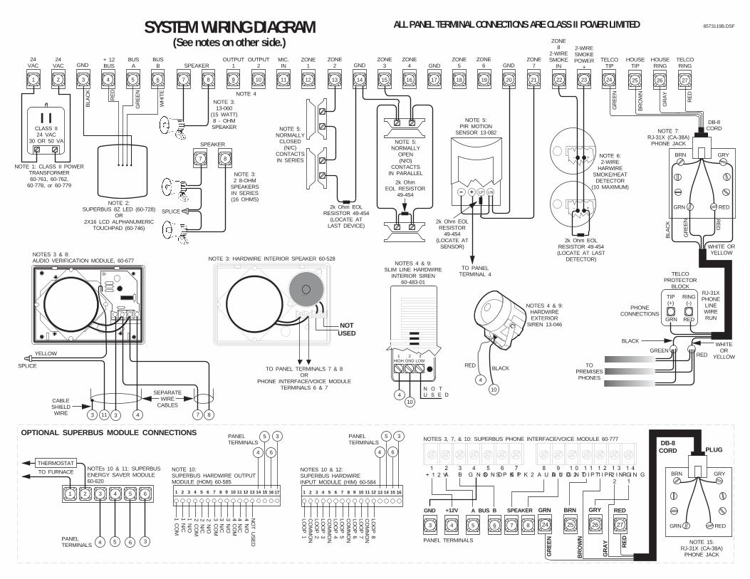
NOTUSED
LP
NOTE 5:PIR MOTION
SENSOR 13-082
- + LN
2k Ohm EOLRESISTOR
49-454(LOCATE AT
SENSOR)
BLA
CK
WH
ITE
GR
EE
N
RE
D
1 2 3 4 5 6 10 11 12 13 14 15 16 17 18 19 20 21
24VAC
24VAC
+ 12BUS
BUSA
BUSB
OUTPUT2GND
MIC.IN
ZONE1
ZONE2
ZONE4GND
ZONE3 GND GND
ZONE5
ZONE6
ZONE7
NOTE 3:13-060
(15 WATT)8 - OHMSPEAKER
NOTE 3:2 8-OHM
SPEAKERSIN SERIES(16 OHMS)
SPLICE
NOTE 1: CLASS II POWERTRANSFORMER60-761, 60-762,
60-778, or 60-779
22 23 24
ZONE8
2-WIRESMOKE
IN
2-WIRESMOKEPOWER
+TELCO
TIP
NOTE 5:NORMALLY
OPEN (N/O)
CONTACTSIN PARALLEL
2k OhmEOL RESISTOR
49-454
2k Ohm EOLRESISTOR 49-454
(LOCATE ATLAST DEVICE)
NOTE 5:NORMALLY
CLOSED(N/C)
CONTACTSIN SERIES
+- NOTE 6:2-WIRE
HARWIRESMOKE/HEATDETECTOR
(10 MAXIMUM)
+-
7 8 9
SPEAKEROUTPUT
1
NOTE 7:RJ-31X (CA-38A)
PHONE JACK
PHONECONNECTIONS
BRN GRY
GRN RED
RE
D
GR
EE
N
WHITE ORYELLOW
BLA
CK
TELCOPROTECTOR
BLOCK
GRN RED
TIP(+)
RING(-)
RJ-31XPHONE
LINEWIRERUN
GREENRED
BLACKWHITE
ORYELLOW
TOPREMISESPHONES
GR
EE
N
BR
OW
N
GR
AY
RE
D
TO PANELTERMINAL 4
2k Ohm EOLRESISTOR 49-454(LOCATE AT LAST
DETECTOR)
SEPARATEWIRE
CABLES
87
SPLICE
YELLOW
CABLESHIELDWIRE
NOTES 3 & 8:AUDIO VERIFICATION MODULE, 60-677
3 11 3 4
DB-8CORD
25 26 27
CLASS II24 VAC
30 OR 50 VA
NOTE 2:SUPERBUS 8Z LED (60-728)
OR2X16 LCD ALPHANUMERIC
TOUCHPAD (60-746)
7 8
HOUSETIP
HOUSERING
TELCORING
ALL PANEL TERMINAL CONNECTIONS ARE CLASS II POWER LIMITED
NOTE 3: HARDWIRE INTERIOR SPEAKER 60-528
1HIGH
2GND
3LOW
N O TU S E D
RED BLACK
410
4
10
NOTES 4 & 9:SLIM LINE HARDWIRE
INTERIOR SIREN60-483-01
NOTES 4 & 9:HARDWIREEXTERIOR
SIREN 13-046
61 2 3 4 5
NOTEs 10 & 11: SUPERBUSENERGY SAVER MODULE60-620
TO FURNACE
THERMOSTAT
1 2 3 4 5 6 7 8 9 10 11 12 13 14 15 16
LOO
P 1
CO
MM
ON
LOO
P 2
LOO
P 3
LOO
P 4
CO
MM
ON
LOO
P 5
LOO
P 6
LOO
P 7
LOO
P 8
CO
MM
ON
CO
MM
ON
NOTES 10 & 12:SUPERBUS HARDWIREINPUT MODULE (HIM) 60-584
13
1 CO
M1 N
/C1 N
/O2 C
OM
2 N/C
2 N/O
3 CO
M3 N
/C3 N
/O4 C
OM
4 N/C
4 N/O
NO
T U
SE
D1 2 3 4 5 6 7 8 9 10 11 12 14 15 16 17
NOTE 10:SUPERBUS HARDWIRE OUTPUTMODULE (HOM) 60-585
4
5
6
3
4 5 6 3
OPTIONAL SUPERBUS MODULE CONNECTIONS
PANELTERMINALS
PANELTERMINALS
PANELTERMINALS
SYSTEM WIRING DIAGRAM(See notes on other side.)
4
5
6
3
1+ 1 2 V
2A
3B
4G N D
5G N D
6S P K 1
7S P K 2
8A U D 1
9A U D 2
1 0G N D
1 1T I P 1
1 2T I P 2
1 3R I N G2
1 4R I N G1
3 4 5 6
+12V A BGND BUS
GR
EE
N
BR
OW
N
GR
AY RE
D
DB-8CORD
25 26 27
GRY RED
PLUG
24
GRN BRN
BRN GRY
GRN RED
NOTE 15:RJ-31X (CA-38A)
PHONE JACK
NOTES 3, 7, & 10: SUPERBUS PHONE INTERFACE/VOICE MODULE 60-777
PANEL TERMINALS
8573119B.DSF
NOTE 4
7 8
SPEAKER
TO PANEL TERMINALS 7 & 8OR
PHONE INTERFACE/VOICE MODULETERMINALS 6 & 7
SPEAKER