Embed Size (px)
Citation preview

Concealed Fastener Steel Roof and Wall Panel
Structural Design Guide
AEP Span Design Guide • July 2014 1www.aepspan.com
Introduction . . . . . . . . . . . . . . . . . . . . . . . . . . . . . . . . . . . . 2-3Concealed Fastener Panels Explained . . . . . . . . . . . . . . . . . . . 2Concealed Fastener Panel Systems . . . . . . . . . . . . . . . . . . . . . . 2
Structural Design Requirements . . . . . . . . . . . . . . 4-6IBC Recognition of Roof and Wall Panels . . . . . . . . . . . . . . . . . 4Product Approval Reports . . . . . . . . . . . . . . . . . . . . . . . . . . . . . . 4Section Properties . . . . . . . . . . . . . . . . . . . . . . . . . . . . . . . . . . . . 4 Panel Design Loads . . . . . . . . . . . . . . . . . . . . . . . . . . . 6-13Design Loads . . . . . . . . . . . . . . . . . . . . . . . . . . . . . . . . . . . . . . . . 6Application of Design Loads . . . . . . . . . . . . . . . . . . . . . . . . . . . . 6Deflection Limits . . . . . . . . . . . . . . . . . . . . . . . . . . . . . . . . . . . . . 6Panel Resistance to Inward (Positive) loads . . . . . . . . . . . . . . . 7Panel Resistance to Outward (Negative) loads . . . . . . . . . . . . . 8Roof Attachment (Point) Loads onto Metal Roofing . . . . . . . 10Photovoltaic (PV) Attachment Considerations . . . . . . . . . . . . 12Drag Loads . . . . . . . . . . . . . . . . . . . . . . . . . . . . . . . . . . . . . . . . . 12How to Specify Product on Drawings . . . . . . . . . . . . . . . . . . . 13
Design Examples . . . . . . . . . . . . . . . . . . . . . . . . . . . . . 14-23
Table of Contents
www.aepspan.com2 AEP Span Design Guide • July 2014
Steel roof and wall panels with their attractive textures and finishes are able to provide the long term durability and environmental protection to resist the most powerful storms nature can hurl towards buildings. The attachment points of concealed fastener panels are hidden, adding to the sleek, clean look of these panels. This combined beauty and durability can easily be specified by the designer to meet a project’s architectural and the structural perfor-mance requirements.
The structural design methods presented in this guide fol-low the International Building Code (IBC) requirements for steel roof and wall panels. This document will guide the designer through common loads applied to the panels including; dead loads, live loads, wind and snow loads. The steel panels resist these loads as a beam, acting in the plane of the roof or wall. The panel’s resisting capacity for inward loads are derived through principles of engineering mechanics as a multi-span beam using the panel’s section properties. The outward capacity of the panels is derived through a combination of full scale uplift testing and the fastener capacity that holds the panel to the substrate. In addition to the inward and outward out-of-plane loads, drag loads are addressed to ensure the panels will not slide off the roof. All of these basic concepts are addressed in the following sections and culminate in detailed design examples.
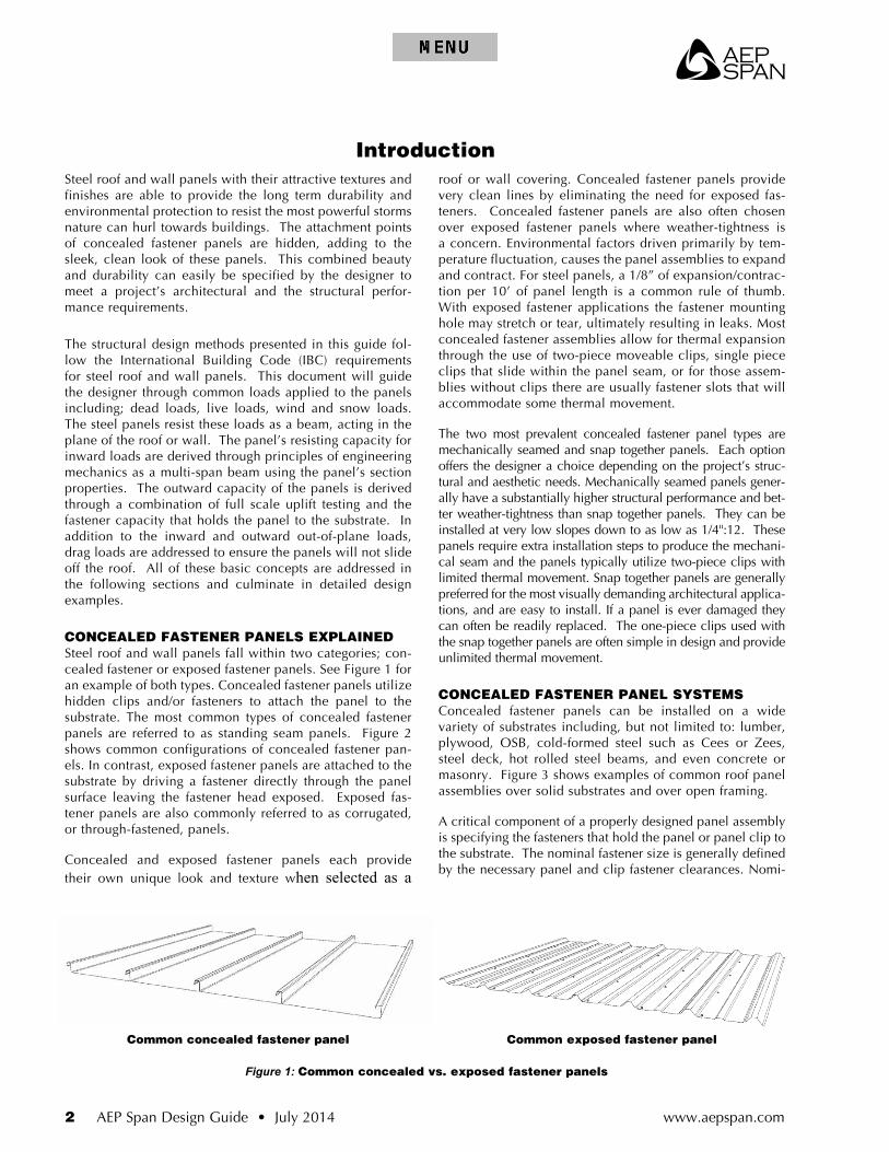
CONCEALED FASTENER PANELS EXPLAINEDSteel roof and wall panels fall within two categories; con-cealed fastener or exposed fastener panels. See Figure 1 for an example of both types. Concealed fastener panels utilize hidden clips and/or fasteners to attach the panel to the substrate. The most common types of concealed fastener panels are referred to as standing seam panels. Figure 2 shows common configurations of concealed fastener pan-els. In contrast, exposed fastener panels are attached to the substrate by driving a fastener directly through the panel surface leaving the fastener head exposed. Exposed fas-tener panels are also commonly referred to as corrugated, or through-fastened, panels.
Concealed and exposed fastener panels each provide their own unique look and texture when selected as a
roof or wall covering. Concealed fastener panels provide very clean lines by eliminating the need for exposed fas-teners. Concealed fastener panels are also often chosen over exposed fastener panels where weather-tightness is a concern. Environmental factors driven primarily by tem-perature fluctuation, causes the panel assemblies to expand and contract. For steel panels, a 1/8” of expansion/contrac-tion per 10’ of panel length is a common rule of thumb. With exposed fastener applications the fastener mounting hole may stretch or tear, ultimately resulting in leaks. Most concealed fastener assemblies allow for thermal expansion through the use of two-piece moveable clips, single piece clips that slide within the panel seam, or for those assem-blies without clips there are usually fastener slots that will accommodate some thermal movement.
The two most prevalent concealed fastener panel types are mechanically seamed and snap together panels. Each option offers the designer a choice depending on the project’s struc-tural and aesthetic needs. Mechanically seamed panels gener-ally have a substantially higher structural performance and bet-ter weather-tightness than snap together panels. They can be installed at very low slopes down to as low as 1/4":12. These panels require extra installation steps to produce the mechani-cal seam and the panels typically utilize two-piece clips with limited thermal movement. Snap together panels are generally preferred for the most visually demanding architectural applica-tions, and are easy to install. If a panel is ever damaged they can often be readily replaced. The one-piece clips used with the snap together panels are often simple in design and provide unlimited thermal movement.
CONCEALED FASTENER PANEL SYSTEMSConcealed fastener panels can be installed on a wide variety of substrates including, but not limited to: lumber, plywood, OSB, cold-formed steel such as Cees or Zees, steel deck, hot rolled steel beams, and even concrete or masonry. Figure 3 shows examples of common roof panel assemblies over solid substrates and over open framing.
A critical component of a properly designed panel assembly is specifying the fasteners that hold the panel or panel clip to the substrate. The nominal fastener size is generally defined by the necessary panel and clip fastener clearances. Nomi-
Common concealed fastener panel Common exposed fastener panel
Figure 1: Common concealed vs. exposed fastener panels
Introduction

AEP Span
AEP Span Design Guide • July 2014 3www.aepspan.com
Mechanical seam Snap together seam
Integral seam Hooked seam
Figure 2: Common concealed fastener panel configurations
nal fastener sizes approved for use with each panel type are defined within a manufacturer’s approval report, in their installation guide, or by contacting the panel manufacturer’s representative. The fastener length, point, and thread type are defined by the underlying substrate type and thickness. Fasteners should be obtained through the panel manufac-turer when possible to ensure that the appropriate fastener is being used and the overall panel assembly capacities have not been jeopardized.
For additional information on panel system components and installation considerations and guidelines, it is advis-able to review the manufacturer’s installation guides and
other product literature; this information is nearly always available on the manufacturer’s website. Installation guides recommend standard roof and wall flashing details for aesthetics and weather resistance. Manufacturers often provide additional information around storage/handling, oil canning, underlayments, attachments, drag loads, thermal movement, as well as other considerations.
Designing concealed fastener roof and wall panels under the prescriptive design provisions of the IBC and per the manufacturer’s recommended guidelines is the foundation for providing a structurally sound, and aesthetically attrac-tive, exterior that will last for decades to come.
Over solid substrate Over open framing
Figure 3: Common concealed fastener panel installations
www.aepspan.com4 AEP Span Design Guide • July 2014
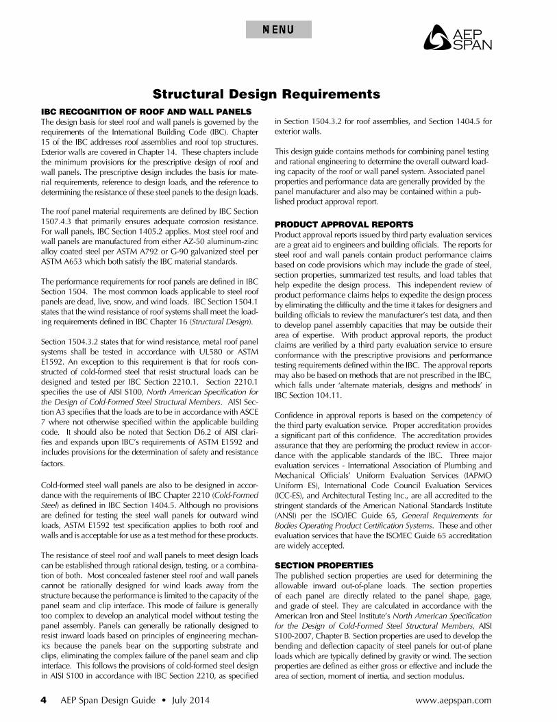
IBC RECOGNITION OF ROOF AND WALL PANELSThe design basis for steel roof and wall panels is governed by the requirements of the International Building Code (IBC). Chapter 15 of the IBC addresses roof assemblies and roof top structures. Exterior walls are covered in Chapter 14. These chapters include the minimum provisions for the prescriptive design of roof and wall panels. The prescriptive design includes the basis for mate-rial requirements, reference to design loads, and the reference to determining the resistance of these steel panels to the design loads.
The roof panel material requirements are defined by IBC Section 1507.4.3 that primarily ensures adequate corrosion resistance. For wall panels, IBC Section 1405.2 applies. Most steel roof and wall panels are manufactured from either AZ-50 aluminum-zinc alloy coated steel per ASTM A792 or G-90 galvanized steel per ASTM A653 which both satisfy the IBC material standards.
The performance requirements for roof panels are defined in IBC Section 1504. The most common loads applicable to steel roof panels are dead, live, snow, and wind loads. IBC Section 1504.1 states that the wind resistance of roof systems shall meet the load-ing requirements defined in IBC Chapter 16 (Structural Design).
Section 1504.3.2 states that for wind resistance, metal roof panel systems shall be tested in accordance with UL580 or ASTM E1592. An exception to this requirement is that for roofs con-structed of cold-formed steel that resist structural loads can be designed and tested per IBC Section 2210.1. Section 2210.1 specifies the use of AISI S100, North American Specification for the Design of Cold-Formed Steel Structural Members. AISI Sec-tion A3 specifies that the loads are to be in accordance with ASCE 7 where not otherwise specified within the applicable building code. It should also be noted that Section D6.2 of AISI clari-fies and expands upon IBC’s requirements of ASTM E1592 and includes provisions for the determination of safety and resistance factors.
Cold-formed steel wall panels are also to be designed in accor-dance with the requirements of IBC Chapter 2210 (Cold-Formed Steel) as defined in IBC Section 1404.5. Although no provisions are defined for testing the steel wall panels for outward wind loads, ASTM E1592 test specification applies to both roof and walls and is acceptable for use as a test method for these products.
The resistance of steel roof and wall panels to meet design loads can be established through rational design, testing, or a combina-tion of both. Most concealed fastener steel roof and wall panels cannot be rationally designed for wind loads away from the structure because the performance is limited to the capacity of the panel seam and clip interface. This mode of failure is generally too complex to develop an analytical model without testing the panel assembly. Panels can generally be rationally designed to resist inward loads based on principles of engineering mechan-ics because the panels bear on the supporting substrate and clips, eliminating the complex failure of the panel seam and clip interface. This follows the provisions of cold-formed steel design in AISI S100 in accordance with IBC Section 2210, as specified
Structural Design Requirements
in Section 1504.3.2 for roof assemblies, and Section 1404.5 for exterior walls.
This design guide contains methods for combining panel testing and rational engineering to determine the overall outward load-ing capacity of the roof or wall panel system. Associated panel properties and performance data are generally provided by the panel manufacturer and also may be contained within a pub-lished product approval report.
PRODUCT APPROVAL REPORTSProduct approval reports issued by third party evaluation services are a great aid to engineers and building officials. The reports for steel roof and wall panels contain product performance claims based on code provisions which may include the grade of steel, section properties, summarized test results, and load tables that help expedite the design process. This independent review of product performance claims helps to expedite the design process by eliminating the difficulty and the time it takes for designers and building officials to review the manufacturer’s test data, and then to develop panel assembly capacities that may be outside their area of expertise. With product approval reports, the product claims are verified by a third party evaluation service to ensure conformance with the prescriptive provisions and performance testing requirements defined within the IBC. The approval reports may also be based on methods that are not prescribed in the IBC, which falls under ‘alternate materials, designs and methods’ in IBC Section 104.11.
Confidence in approval reports is based on the competency of the third party evaluation service. Proper accreditation provides a significant part of this confidence. The accreditation provides assurance that they are performing the product review in accor-dance with the applicable standards of the IBC. Three major evaluation services - International Association of Plumbing and Mechanical Officials’ Uniform Evaluation Services (IAPMO Uniform ES), International Code Council Evaluation Services (ICC-ES), and Architectural Testing Inc., are all accredited to the stringent standards of the American National Standards Institute (ANSI) per the ISO/IEC Guide 65, General Requirements for Bodies Operating Product Certification Systems. These and other evaluation services that have the ISO/IEC Guide 65 accreditation are widely accepted.
SECTION PROPERTIESThe published section properties are used for determining the allowable inward out-of-plane loads. The section properties of each panel are directly related to the panel shape, gage, and grade of steel. They are calculated in accordance with the American Iron and Steel Institute’s North American Specification for the Design of Cold-Formed Steel Structural Members, AISI S100-2007, Chapter B. Section properties are used to develop the bending and deflection capacity of steel panels for out-of plane loads which are typically defined by gravity or wind. The section properties are defined as either gross or effective and include the area of section, moment of inertia, and section modulus.
AEP Span
AEP Span Design Guide • July 2014 5www.aepspan.com
Panel Gage
Effective SectionPropertiesare Identified bythe Subscript, e
Weight of PanelSectionper sq/ft
Gross Section Propertiesare Identified by the Subscript, g
Base Metal Thickness(without coating)
Effective Net Areaof Section
Hybrid Moment ofinertia fo UniformLoad Condition Only
Positive and NegativeEffective Moment ofInertia for Non-uniformLoad Conditions
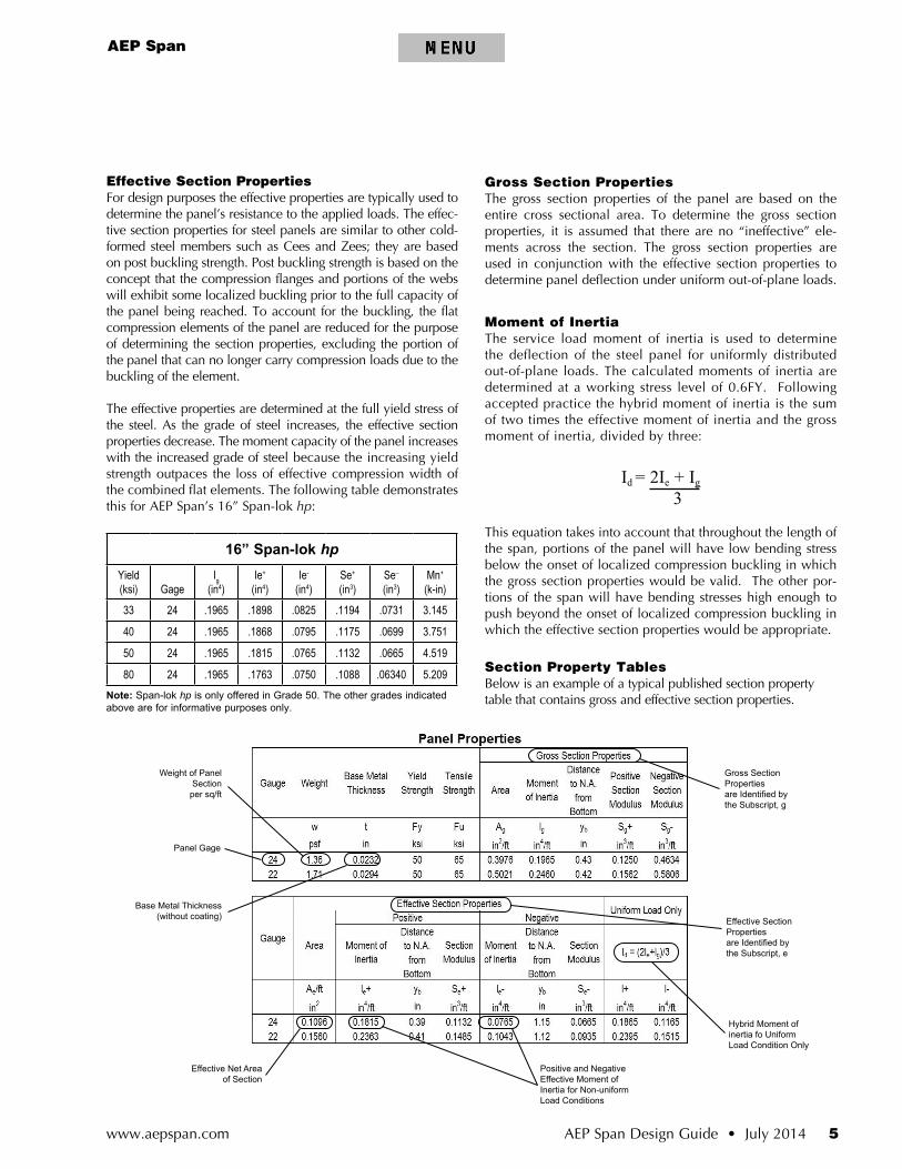
Effective Section PropertiesFor design purposes the effective properties are typically used to determine the panel’s resistance to the applied loads. The effec-tive section properties for steel panels are similar to other cold-formed steel members such as Cees and Zees; they are based on post buckling strength. Post buckling strength is based on the concept that the compression flanges and portions of the webs will exhibit some localized buckling prior to the full capacity of the panel being reached. To account for the buckling, the flat compression elements of the panel are reduced for the purpose of determining the section properties, excluding the portion of the panel that can no longer carry compression loads due to the buckling of the element.
The effective properties are determined at the full yield stress of the steel. As the grade of steel increases, the effective section properties decrease. The moment capacity of the panel increases with the increased grade of steel because the increasing yield strength outpaces the loss of effective compression width of the combined flat elements. The following table demonstrates this for AEP Span’s 16” Span-lok hp:
16” Span-lok hpYield (ksi) Gage
Ig (in4)
Ie+ (in4)
Ie-
(in4)Se+ (in3)
Se–
(in3)Mn+ (k-in)
33 24 .1965 .1898 .0825 .1194 .0731 3.145
40 24 .1965 .1868 .0795 .1175 .0699 3.751
50 24 .1965 .1815 .0765 .1132 .0665 4.519
80 24 .1965 .1763 .0750 .1088 .06340 5.209Note: Span-lok hp is only offered in Grade 50 . The other grades indicated above are for informative purposes only .
Gross Section PropertiesThe gross section properties of the panel are based on the entire cross sectional area. To determine the gross section properties, it is assumed that there are no “ineffective” ele-ments across the section. The gross section properties are used in conjunction with the effective section properties to determine panel deflection under uniform out-of-plane loads.
Moment of Inertia The service load moment of inertia is used to determine the deflection of the steel panel for uniformly distributed out-of-plane loads. The calculated moments of inertia are determined at a working stress level of 0.6FY. Following accepted practice the hybrid moment of inertia is the sum of two times the effective moment of inertia and the gross moment of inertia, divided by three:
Id = 2Ie + Ig
3
This equation takes into account that throughout the length of the span, portions of the panel will have low bending stress below the onset of localized compression buckling in which the gross section properties would be valid. The other por-tions of the span will have bending stresses high enough to push beyond the onset of localized compression buckling in which the effective section properties would be appropriate.
Section Property TablesBelow is an example of a typical published section property table that contains gross and effective section properties.

www.aepspan.com6 AEP Span Design Guide • July 2014
DESIGN LOADSDesign loads applied to steel roof and wall panels should be in accordance with ASCE 7. Inward and outward wind loads, and the internal building pressure due to wind loads, are resisted by the roof and wall panels. Roof panels are also subject to gravity loads including dead, live, and snow. The following are the load combinations from ASCE 7-10 that apply to roof and wall panels that include wind.
ASD D + 0 .6W
D + 0 .75L + 0 .75(0 .6W) + 0 .75(Lf or S or R)
0 .6D + 0 .6W
LRFD 1 .2D + 1 .6(Lf or S or R) + 0 .5W
1 .2D + W + L + 0 .5(Lf or S or R)
0.9D + W
For load combinations that include wind, the wind loads can be multiplied by 0.67 for roof panels satisfying spe-cific requirements in Appendix A, Section D6.2.1a of AISI S100-07. Conditions (b) and (c) are the responsibility of the engineer of record. Conditions (a) and (d-g) can be con-firmed by the metal roof panel manufacturer. These can be confirmed via the manufacturer’s approval report, or by verifying with the metal roof panel representative directly. Refer to the AISI excerpt below:
D6.2.1a Strength [Resistance] of Standing Seam Roof Panel Systems
In addition to the provisions provided in Section D6.2.1, for load combinations that include wind uplift, the nominal wind load shall be permitted to be multiplied by 0.67 provided the tested system and wind load evaluation satisfies the following conditions:
(a) The roof system is tested in accordance with AISI S906.
(b) The wind load is calculated using ASCE/SEI 7 for com-ponents and cladding, Method 1 (Simplified Procedure) or Method 2 (Analytical Procedure).
(c) The area of the roof being evaluated is in Zone 2 (edge zone) or Zone 3 (comer zone), as defined in ASCE/SEI 7, i.e. the 0.67 factor does not apply to the field of the roof (Zone 1).
(d) The base metal thickness of the standing seam roof panel is greater than or equal to 0.023 in. (0.59 mm) and less than or equal to 0.030 in. (0.77 mm).
(e) For trapezoidal profile standing seam roof panels, the dis-tance between sidelaps is no greater than 24 in. (610 mm).
(f) For vertical rib profile standing seam roof panels, the dis-
Panel Design Loads
tance between sidelaps is no greater than 18 in. (460 mm).
(g) The observed failure mode of the tested system is one of the following:
(i) The standing seam roof clip mechanically fails by sepa-rating from the panel sidelap.
(ii) The standing seam roof clip mechanically fails by the
sliding tab separating from the stationary base.
APPLICATION OF DESIGN LOADSThe application of design loads to the steel roof or wall panels is dependent upon the substrate that supports the panels. The panels may be installed on solid substrates such as plywood, OSB, steel deck, or concrete. Panels may also be installed over open framing such as joists, purlins, beams, and skip sheeting. These loads should be applied using the load combinations defined in ASCE 7.
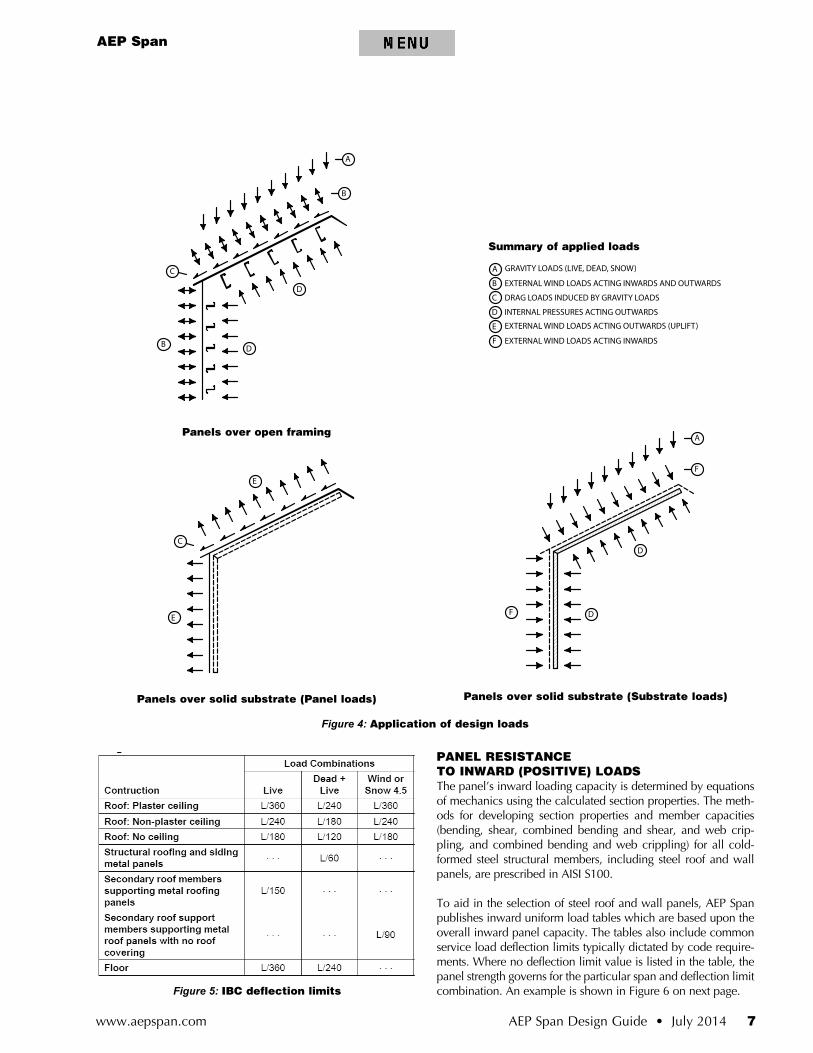
Panels installed over solid substrates do not carry all of the design loads. It is assumed that the solid substrate carries all inward loads including the external wind loads acting inwards, and the dead, live, and snow gravity loads. Panel clips may raise the panel up to ½” above the solid substrate but the flat pan of the panel will deflect under the maxi-mum design loads, transferring these loads directly to the substrate. Any influence of the panel’s strong axis bending capacity is ignored with this assumption. External wind loads acting outwards (wind uplift) is resisted by the panel and the loads transferred to the substrate through the panel fasteners. The internal building pressure (acting outward) is resisted by the solid substrate. This assumption is based on the premise that in the short duration of the design wind gust, the internal pressure will not have time to build and infiltrate through the solid substrate and pressurize the underside of the steel roof or wall panels. See Figure 4.
When installed over open framing the panel will carry all of the design loads and transfer these loads to the support fram-ing members. The panel must support the gravity loads which include dead, live, and snow loads. The panels must also carry the net inward and outward wind loads. See Figure 4.
DEFLECTION LIMITSRoof and wall panels deflect under inward and outward loads. These deflections are generally restricted to the L/60 limit as defined in the International Building Code (IBC), Chapter 16, Table 1604.3. See Figure 5. The IBC prescribes deflection limits to address the fact the roof assemblies are comprised of several materials that have varied stiffness and to limit the possibility of perceivable vibrations. For structural roofing and siding panels the table indicates a recommended deflection limit of L/60 for combined dead and live loads. Since steel roof and wall panels generally do not directly support brittle or vibra-tion/ deflection sensitive interior finish materials, an L/60 deflection limit is appropriate in most cases.
AEP Span
AEP Span Design Guide • July 2014 7www.aepspan.com
Figure 4: Application of design loads
Panels over open framing
Panels over solid substrate (Panel loads) Panels over solid substrate (Substrate loads)
PANEL RESISTANCE TO INWARD (POSITIVE) LOADSThe panel’s inward loading capacity is determined by equations of mechanics using the calculated section properties. The meth-ods for developing section properties and member capacities (bending, shear, combined bending and shear, and web crip-pling, and combined bending and web crippling) for all cold-formed steel structural members, including steel roof and wall panels, are prescribed in AISI S100.
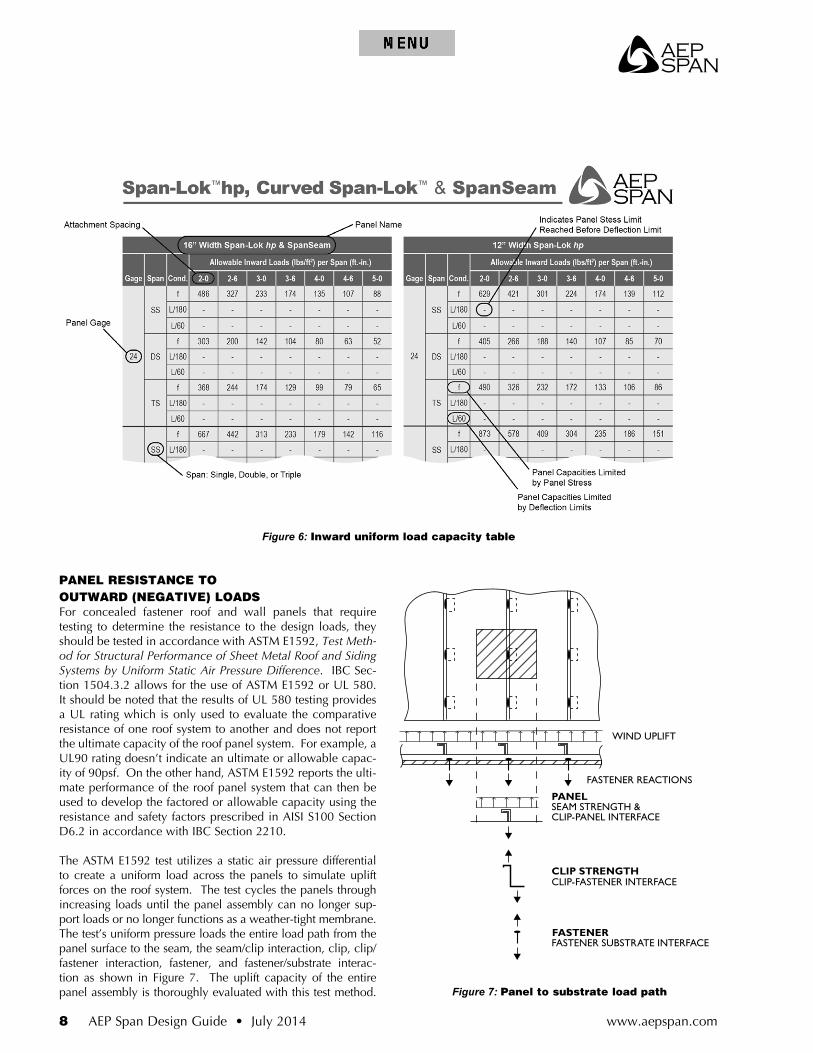
To aid in the selection of steel roof and wall panels, AEP Span publishes inward uniform load tables which are based upon the overall inward panel capacity. The tables also include common service load deflection limits typically dictated by code require-ments. Where no deflection limit value is listed in the table, the panel strength governs for the particular span and deflection limit combination. An example is shown in Figure 6 on next page.Figure 5: IBC deflection limits
Summary of applied loads
www.aepspan.com8 AEP Span Design Guide • July 2014
PANEL RESISTANCE TO OUTWARD (NEGATIVE) LOADSFor concealed fastener roof and wall panels that require testing to determine the resistance to the design loads, they should be tested in accordance with ASTM E1592, Test Meth-od for Structural Performance of Sheet Metal Roof and Siding Systems by Uniform Static Air Pressure Difference. IBC Sec-tion 1504.3.2 allows for the use of ASTM E1592 or UL 580. It should be noted that the results of UL 580 testing provides a UL rating which is only used to evaluate the comparative resistance of one roof system to another and does not report the ultimate capacity of the roof panel system. For example, a UL90 rating doesn’t indicate an ultimate or allowable capac-ity of 90psf. On the other hand, ASTM E1592 reports the ulti-mate performance of the roof panel system that can then be used to develop the factored or allowable capacity using the resistance and safety factors prescribed in AISI S100 Section D6.2 in accordance with IBC Section 2210.
The ASTM E1592 test utilizes a static air pressure differential to create a uniform load across the panels to simulate uplift forces on the roof system. The test cycles the panels through increasing loads until the panel assembly can no longer sup-port loads or no longer functions as a weather-tight membrane. The test’s uniform pressure loads the entire load path from the panel surface to the seam, the seam/clip interaction, clip, clip/fastener interaction, fastener, and fastener/substrate interac-tion as shown in Figure 7. The uplift capacity of the entire panel assembly is thoroughly evaluated with this test method.
Figure 6: Inward uniform load capacity table
FASTENER REACTIONS
PANELSEAM STRENGTH &CLIP-PANEL INTERFACE
CLIP STRENGTHCLIP-FASTENER INTERFACE
FASTENERFASTENER SUBSTRATE INTERFACE
WIND UPLIFT
Figure 7: Panel to substrate load path
AEP Span
AEP Span Design Guide • July 2014 9www.aepspan.com
To generate test results with the widest applicability, some test variables are eliminated as possible modes of failure. Fastener strengths and pull-out resistance from the substrate can be obtained through fastener testing or through prescriptive fas-tener design methods. The clip capacity, clip-seam interface, panel and seam strengths cannot be rationally designed using engineering mechanics for most concealed fastener panels. To ensure that the test’s mode of failure is related to the panel/clip assembly and not the fastener, the fasteners and substrates are intentionally overd esigned to ensure they do not fail in the test.
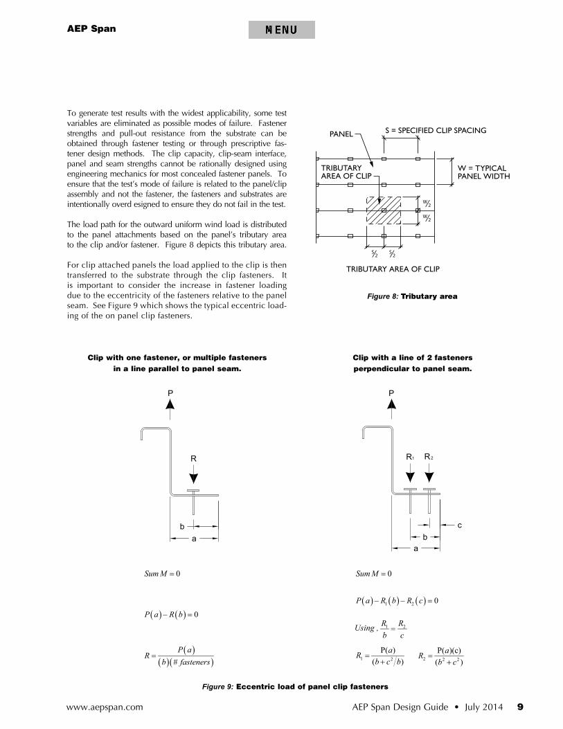
The load path for the outward uniform wind load is distributed to the panel attachments based on the panel’s tributary area to the clip and/or fastener. Figure 8 depicts this tributary area.
For clip attached panels the load applied to the clip is then transferred to the substrate through the clip fasteners. It is important to consider the increase in fastener loading due to the eccentricity of the fasteners relative to the panel seam. See Figure 9 which shows the typical eccentric load-ing of the on panel clip fasteners.
PANEL S = SPECIFIED CLIP SPACING
TRIBUTARYAREA OF CLIP
W = TYPICALPANEL WIDTH
W⁄2W⁄2
S⁄2 S⁄2TRIBUTARY AREA OF CLIP
Figure 8: Tributary area
a
cb
P
R R21
ab
P
R
1 2
P( )( )
aRb c b
=+ 2 2 2
P( )(c)( )
aRb c
=+
Figure 9: Eccentric load of panel clip fasteners
( )( )( )#
P aR
b fasteners=
( ) ( ) 0P a R b− =
0Sum M =
( ) ( ) ( )1 2 0P a R b R c− − =
0Sum M =
Clip with a line of 2 fasteners perpendicular to panel seam.
Clip with one fastener, or multiple fasteners in a line parallel to panel seam.
1 2R Rb c=Using ,
www.aepspan.com10 AEP Span Design Guide • July 2014
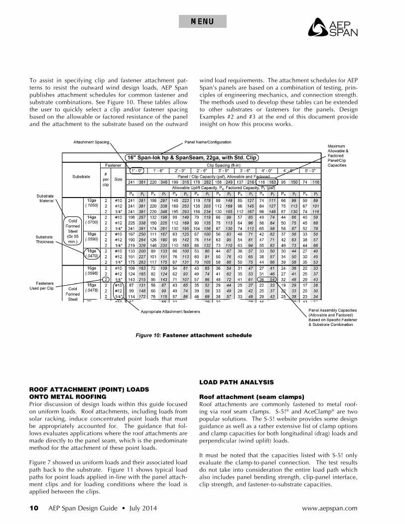
To assist in specifying clip and fastener attachment pat-terns to resist the outward wind design loads, AEP Span publishes attachment schedules for common fastener and substrate combinations. See Figure 10. These tables allow the user to quickly select a clip and/or fastener spacing based on the allowable or factored resistance of the panel and the attachment to the substrate based on the outward
wind load requirements. The attachment schedules for AEP Span’s panels are based on a combination of testing, prin-ciples of engineering mechanics, and connection strength. The methods used to develop these tables can be extended to other substrates or fasteners for the panels. Design Examples #2 and #3 at the end of this document provide insight on how this process works.
Figure 10: Fastener attachment schedule
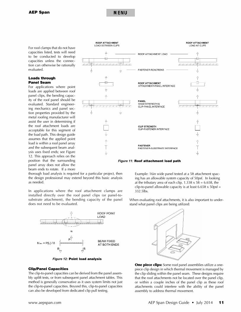
ROOF ATTACHMENT (POINT) LOADS ONTO METAL ROOFINGPrior discussion of design loads within this guide focused on uniform loads. Roof attachments, including loads from solar racking, induce concentrated point loads that must be appropriately accounted for. The guidance that fol-lows evaluates applications where the roof attachments are made directly to the panel seam, which is the predominate method for the attachment of these point loads.
Figure 7 showed us uniform loads and their associated load path back to the substrate. Figure 11 shows typical load paths for point loads applied in-line with the panel attach-ment clips and for loading conditions where the load is applied between the clips.
LOAD PATH ANALYSIS
Roof attachment (seam clamps)Roof attachments are commonly fastened to metal roof-ing via roof seam clamps. S-5!® and AceClamp® are two popular solutions. The S-5! website provides some design guidance as well as a rather extensive list of clamp options and clamp capacities for both longitudinal (drag) loads and perpendicular (wind uplift) loads.
It must be noted that the capacities listed with S-5! only evaluate the clamp-to-panel connection. The test results do not take into consideration the entire load path which also includes panel bending strength, clip-panel interface, clip strength, and fastener-to-substrate capacities.
AEP Span
AEP Span Design Guide • July 2014 11www.aepspan.com
For roof clamps that do not have capacities listed, tests will need to be conducted to develop capacities unless the connec-tion can otherwise be rationally evaluated.
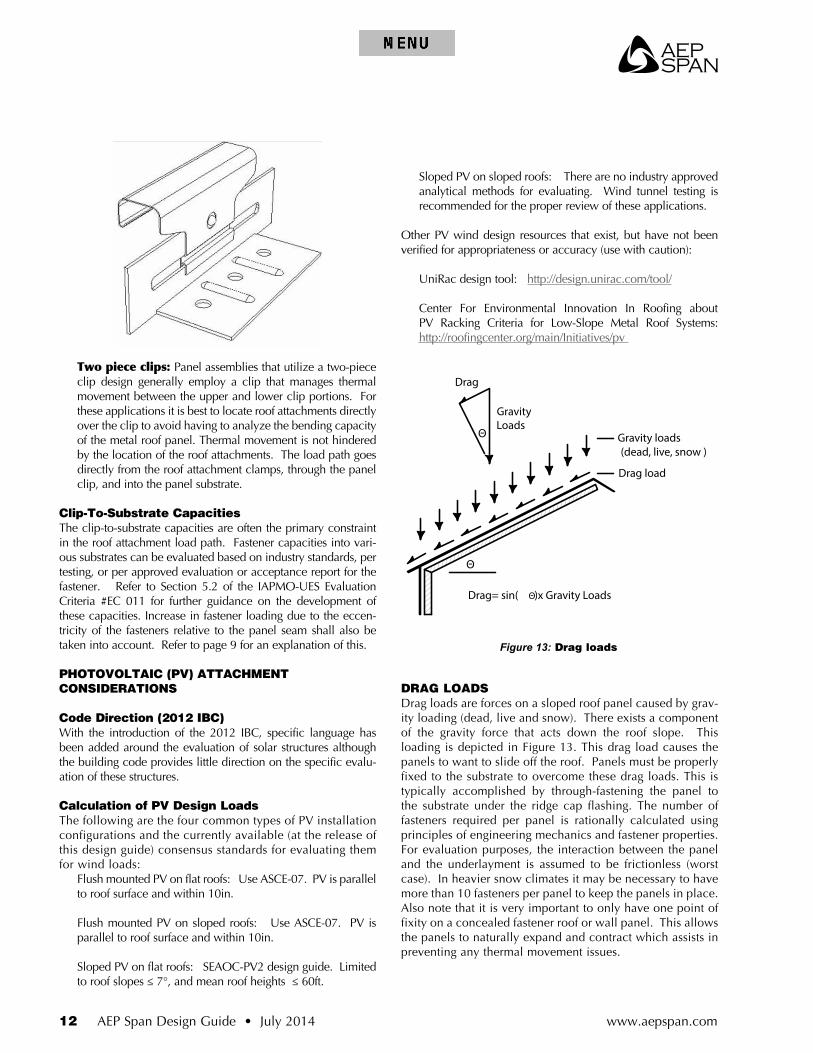
Loads through Panel SeamFor applications where point loads are applied between roof panel clips, the bending capac-ity of the roof panel should be evaluated. Standard engineer-ing mechanics and panel sec-tion properties provided by the metal roofing manufacturer will assist the user in determining if the roof attachment loads are acceptable for this segment of the load path. This design guide assumes that the applied point load is within a roof panel array and the subsequent beam anal-ysis uses fixed ends; see Figure 12. This approach relies on the position that the surrounding panel array does not allow the beam ends to rotate. If a more thorough load analysis is required for a particular project, then the design professional may extend beyond this basic analysis as needed.
In applications where the roof attachment clamps are installed directly over the roof panel clips (or panel-to-substrate attachment), the bending capacity of the panel does not need to be evaluated.
Clip/Panel CapacitiesThe clip-to-panel capacities can be derived from the panel assem-bly uplift tests, or from subsequent panel attachment tables. This method is generally conservative as it uses system limits not just the clip-to-panel capacities. Beyond this, clip-to-panel capacities can also be developed from dedicated clip pull testing.
Example: 16in wide panel tested at a 5ft attachment spac-ing has an allowable system capacity of 50psf. In looking at the tributary area of each clip, 1.33ft x 5ft = 6.65ft, the clip-to-panel allowable capacity is at least 6.65ft x 50psf = 332.5lbs.
When evaluating roof attachments, it is also important to under-stand what panel clips are being utilized:
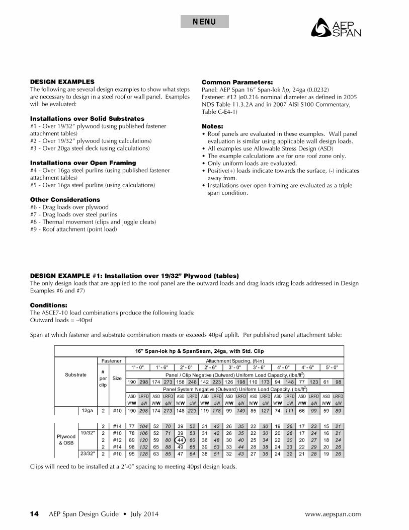
One piece clips: Some roof panel assemblies utilize a one-piece clip design in which thermal movement is managed by the clip sliding within the panel seam. These designs require that the roof attachments not be located over the panel clip, or within a couple inches of the panel clip as these roof attachments could interfere with the ability of the panel assembly to address thermal movement.
Figure 11: Roof attachment load path
Figure 12: Point load analysis
www.aepspan.com12 AEP Span Design Guide • July 2014
Sloped PV on sloped roofs: There are no industry approved analytical methods for evaluating. Wind tunnel testing is recommended for the proper review of these applications.
Other PV wind design resources that exist, but have not been verified for appropriateness or accuracy (use with caution):
UniRac design tool: http://design.unirac.com/tool/
Center For Environmental Innovation In Roofing about PV Racking Criteria for Low-Slope Metal Roof Systems: http://roofingcenter.org/main/Initiatives/pv
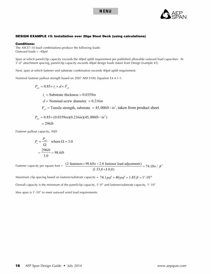
DRAG LOADSDrag loads are forces on a sloped roof panel caused by grav-ity loading (dead, live and snow). There exists a component of the gravity force that acts down the roof slope. This loading is depicted in Figure 13. This drag load causes the panels to want to slide off the roof. Panels must be properly fixed to the substrate to overcome these drag loads. This is typically accomplished by through-fastening the panel to the substrate under the ridge cap flashing. The number of fasteners required per panel is rationally calculated using principles of engineering mechanics and fastener properties. For evaluation purposes, the interaction between the panel and the underlayment is assumed to be frictionless (worst case). In heavier snow climates it may be necessary to have more than 10 fasteners per panel to keep the panels in place. Also note that it is very important to only have one point of fixity on a concealed fastener roof or wall panel. This allows the panels to naturally expand and contract which assists in preventing any thermal movement issues.
Figure 13: Drag loads
Two piece clips: Panel assemblies that utilize a two-piece clip design generally employ a clip that manages thermal movement between the upper and lower clip portions. For these applications it is best to locate roof attachments directly over the clip to avoid having to analyze the bending capacity of the metal roof panel. Thermal movement is not hindered by the location of the roof attachments. The load path goes directly from the roof attachment clamps, through the panel clip, and into the panel substrate.
Clip-To-Substrate CapacitiesThe clip-to-substrate capacities are often the primary constraint in the roof attachment load path. Fastener capacities into vari-ous substrates can be evaluated based on industry standards, per testing, or per approved evaluation or acceptance report for the fastener. Refer to Section 5.2 of the IAPMO-UES Evaluation Criteria #EC 011 for further guidance on the development of these capacities. Increase in fastener loading due to the eccen-tricity of the fasteners relative to the panel seam shall also be taken into account. Refer to page 9 for an explanation of this.
PHOTOVOLTAIC (PV) ATTACHMENT CONSIDERATIONS
Code Direction (2012 IBC)With the introduction of the 2012 IBC, specific language has been added around the evaluation of solar structures although the building code provides little direction on the specific evalu-ation of these structures.
Calculation of PV Design LoadsThe following are the four common types of PV installation configurations and the currently available (at the release of this design guide) consensus standards for evaluating them for wind loads:
Flush mounted PV on flat roofs: Use ASCE-07. PV is parallel to roof surface and within 10in.
Flush mounted PV on sloped roofs: Use ASCE-07. PV is parallel to roof surface and within 10in.
Sloped PV on flat roofs: SEAOC-PV2 design guide. Limited to roof slopes ≤ 7°, and mean roof heights ≤ 60ft.

AEP Span
AEP Span Design Guide • July 2014 13www.aepspan.com
HOW TO SPECIFY PRODUCT ON DRAWINGSCorrectly specifying steel roof and wall panels on the design drawings is important to ensure that the desired panel is speci-fied and attached to the structure in a manner that will resist the required design loads.
Traditionally panels have been selected by the architect and then the manufacturer or specialty engineer provides engi-neering services to determine the panel attachment to the structure as a deferred structural submittal. Some jurisdictions such as the California Division of the State Architect are now requiring the steel roof and wall panels to be fully engineered and submitted for design review prior to construction permits being issued.
Deferred engineering submittals can create problems if the selected steel roof or wall panel assembly is not capable of meeting the project’s load requirements. This can lead to addendums being issued to adjust the specified panel which may lead to costly changes during the project’s construction phase. If the correct panel and attachment schedule is speci-fied and clearly shown on the contract drawings, the risk of these costly changes can be reduced by ensuring the desired panel is capable of meeting the structural requirements.
Attachment ZonesThe primary requirement that defines the attachment of steel roof and wall panels is outward wind loading. It can be dif-ficult to describe the clip and fastener spacing for a particular building area within the specifications, therefore conveying the information on the architectural or structural design draw-ings is a useful and effective option.
To provide the least installed cost to the building owner, the attachment spacing should vary based on the design loads. A zone map of the roof and/or building elevations showing the uplift pressure zones is a good basis for providing the attachment spacing optimized for each zone. Figure 14 is an example of a gable roof plan with clearly identified zones. On simple projects the zones may be numbered 1, 2 and 3 follow-ing the zone designations outlined in ASCE-7 for wind loads. For complex roof configurations with more than three zones, the designer will need to provide an alternate numbering or lettering system to describe all the zones on the building.
Attachment ScheduleThe attachment schedules for steel roof and wall panels should use an optimized clip and fastener spacing for each building wind zone. The attachment spacing should be defined by the outward panel loading but not exceed the support spacing required for the inward panel loads. The schedule should include the following information:
• Clip type and spacing.• Fastener type and spacing.
See Figure 15 for an example of panel attachment schedule. Optional information would be to include drag load fastener requirements. The drag load attachment could also be con-veyed in the details on the plans if the project does not require different zones for drag load fasteners. Drag load require-ments would include:
• Drag fastener type and quantity.
Figure 14: Wind zone map
Steel Roof Panel Schedule
Zone Panel Clip Clip Fasteners Drag Fasteners
Manufacturer Type Width, in Gage Type Spacing,
in Type Quantity Type Quantity
A AEP Span Span-Lok hp 16 24 2-1/2” Std 60 #12 2 #14 3
B AEP Span Span-Lok hp 16 24 2-1/2” Std 36 #12 2 #14 3
C AEP Span Span-Lok hp 16 24 2-1/2” Std 12 #12 2 #14 3
Figure 15: Panel Attachment schedule
HH
B
B
A
C
L1
L2
BC
AB
BC B
C
MEAN HEIGHT
B
A
B
B
A
B
C
B
C
C
B
C
C
B
C
C
B
C
ROOF ZONE PLAN
SLOPE
SLOPE
www.aepspan.com14 AEP Span Design Guide • July 2014
DESIGN EXAMPLESThe following are several design examples to show what steps are necessary to design in a steel roof or wall panel. Examples will be evaluated:
Installations over Solid Substrates#1 - Over 19/32” plywood (using published fastener attachment tables)#2 - Over 19/32” plywood (using calculations)#3 - Over 20ga steel deck (using calculations)
Installations over Open Framing#4 - Over 16ga steel purlins (using published fastener attachment tables)#5 - Over 16ga steel purlins (using calculations)
Other Considerations#6 - Drag loads over plywood#7 - Drag loads over steel purlins#8 - Thermal movement (clips and joggle cleats)#9 - Roof attachment (point load)
Common Parameters:Panel: AEP Span 16” Span-lok hp, 24ga (0.0232)Fastener: #12 (ø0.216 nominal diameter as defined in 2005 NDS Table 11.3.2A and in 2007 AISI S100 Commentary, Table C-E4-1)
Notes:• Roof panels are evaluated in these examples. Wall panel
evaluation is similar using applicable wall design loads. • All examples use Allowable Stress Design (ASD)• The example calculations are for one roof zone only.• Only uniform loads are evaluated.• Positive(+) loads indicate towards the surface, (-) indicates
away from.• Installations over open framing are evaluated as a triple
span condition.
DESIGN EXAMPLE #1: Installation over 19/32” Plywood (tables)The only design loads that are applied to the roof panel are the outward loads and drag loads (drag loads addressed in Design Examples #6 and #7)
Conditions:The ASCE7-10 load combinations produce the following loads:Outward loads = -40psf
Span at which fastener and substrate combination meets or exceeds 40psf uplift. Per published panel attachment table:
Clips will need to be installed at a 2’-0” spacing to meeting 40psf design loads.
190 174 158 142 126 110 94 77 61
ASD W/W
ASD W/W
ASD W/W
ASD W/W
ASD W/W
ASD W/W
ASD W/W
ASD W/W
ASD W/W
2 #10 190 174 148 119 99 85 74 66 592 #12 190 174 158 135 112 96 84 75 612 1/4" 190 174 158 142 126 110 94 77 612 #10 190 132 99 79 66 57 49 44 402 #12 190 150 112 90 75 64 56 50 452 1/4" 190 174 130 104 87 74 65 58 522 #10 167 111 83 67 56 48 42 37 332 #12 190 126 95 76 63 54 47 42 382 1/4" 190 146 110 88 73 63 55 49 442 #10 133 89 66 53 44 38 33 30 272 #12 151 101 76 60 50 43 38 34 302 1/4" 175 117 87 70 58 50 44 39 352 #10 109 72 54 43 36 31 27 24 222 #12 124 82 62 49 41 35 31 27 252 1/4" 143 95 71 57 48 41 36 32 292 #10 87 58 43 35 29 25 22 19 172 #12 99 66 49 39 33 28 25 22 202 1/4" 114 76 57 46 38 33 29 25 232 #10 65 43 33 26 22 19 16 14 132 #12 74 49 37 30 25 21 19 16 152 1/4" 86 57 43 34 29 25 21 19 172 #10 54 36 27 22 18 16 14 12 112 #12 62 41 31 25 21 18 15 14 122 1/4" 71 48 36 29 24 20 18 16 142 #10 62 41 31 25 21 18 15 14 122 #12 70 47 35 28 23 20 18 16 142 #14 77 52 39 31 26 22 19 17 152 #10 78 52 39 31 26 22 20 17 162 #12 89 59 44 36 30 25 22 20 182 #14 98 65 49 39 33 28 24 22 202 #10 95 63 47 38 32 27 24 21 192 #12 108 72 54 43 36 31 27 24 222 #14 118 79 59 47 39 34 30 26 242 #10 156 104 78 62 52 45 39 35 312 #12 177 118 89 71 59 51 44 39 352 #14 190 130 98 78 65 56 49 43 39
Lumber(DFL)
1" min
Cold Formed
Steel (Gr 33 min.)
16ga (.0598)
18ga (.0478)
20ga (.0359)
22ga (.0299)
Plywood & OSB
15/32"
19/32"
23/32"
LRFD φW
Cold Formed
Steel(Gr 55 min.)
12ga (.1050)
14ga (.0700)
16ga (.0590)
18ga (.0470)
298 273 223
98Panel System Negative (Outward) Uniform Load Capacity, (lbs/ft2)
LRFD φW
LRFD φW
LRFD φW
LRFD φW
LRFD φW
LRFD φW
LRFD φW
LRFD φW
5' - 0"Panel / Clip Negative (Outward) Uniform Load Capacity, (lbs/ft2)
298 273 248 223 198 173 148 123
2' - 0" 2' - 6" 3' - 0" 3' - 6" 4' - 0" 4' - 6"
16" Span-lok hp & SpanSeam, 24ga, with Std. Clip
Substrate
Fastener Attachment Spacing, (ft-in)
# per clip
Size
1' - 0" 1' - 6"
178 149 127 111 99 89
149 119 99
298 273 248 203 169248
59223 195 167
127 113 9814598146
87
85123
74 66298
130 112
297 198
71 5062 56
75298 261 195 156 98298
284 190 142
78250 167 125 100 83
298 220 165 132 110 94
53227
65 54
66200 133 100 80 67
263 175 131 105 88 75
84
65
33
151 113 91 7644 40
47
31 27
273
225 169
62
37
86
109 81163
68135 113 96
41 36
50 45
114 95 81 71
58
73
66
82
5757 50
46
63 57
104 70 52 42
32 28
41215 143 107 86
53185 124 93 74
98 65 49 39
37
131 87 65 52 4448
33 29 26
172 115 86 69 57 43 38
25
3433 28 24 22 20
2265 52 43 37
49
32 29 2682 55 41 33 27 16
12918
21
1942 33 28 2454 43 36 31
2124
93 6227 24107 72
47 37
107 80
56
3571
128 85
120 80
53
24
19 178395 63 47
3023 21
30
111 74 56 44
2142
21
30 26
160
36 32
2753
24
64 51
40
43
148
6470 60
99 74
10660 48
46211 141 105 84
88
49
132
146 97 73
53
32
488059 53
53
88
4240
29 26
47 42
363236
332628
37
68 60
49 42
96
34
58
26
27
23
59
20
37
54
264 75 66
38
239106
61 4372
33
29
3035
53
23
160176
120132
21 19
66 44
38 32

AEP Span
AEP Span Design Guide • July 2014 15www.aepspan.com
DESIGN EXAMPLE #2: Installation over 19/32” Plywood (using calculations)Conditions:The ASCE7-10 load combinations produce the following loads:
Outward loads = -40psf
Span at which panel/clip capacity exceeds the 40psf uplift requirement per published allowable outward load capacities (independent of fastener/substrate) via product sheets, manufacturer representative, or similar.
Panels installed at 5’-0” exceed 40psf design loads (panel capacity, not fastener/substrate capacity), taken from product sheet.
Next, span at which fastener and substrate combination exceeds 40psf uplift requirement.
Fastener pullout strength per NDS Equation 11.2-2: 22850 G D× ×
G = 0.45 (Plywood and OSB) as specified in The Engineered Wood Association APA #TT-051C 22850 0.45 0.216 124.6 /lbs in× × =
ASD Adjustment factors per NDS Table 10.3.1: tot D M t eg tnC C C C C C= × × × ×
1.6 1.0 1.0 1.0 1.0 1.6totC = × × × × =
Fastener pullout capacity =
19124.6 1.6 118.4
32lbs
in lbsin
× × =
Fastener capacity per square foot =
Determine fastener load adjustment using engineering mechanics (refer to design guide) and clip dimensions.
Combined fastener adjustment = 1.36+0.64 =2.0
Fastener capacity per square foot = 2(2 118.4 2.0)89.0 /
(1.33 1.0 )lbs
lbs ftft ft
× ÷=
×Maximum clip spacing based on fastener/substrate capacity = 89.0 40 2.22 2 ' 3"psf psf ft÷ = = −
Overall capacity is the minimum of the panel/clip capacity, 5’-0” and fastener/substrate capacity, 2’-3”
Max span is 2’-3” to meet outward wind load requirements.
Note: This design example shows usage of the Span-Lok hp Standard Clip although applications over solid substrate often utilize the Low Profile Clip with its lower standoff (not shown).
1 2
P( )1.36( )
( )a
R Pb c b
= =+
2 2 2
P( )(c)0.64( )
( )a
R Pb c
= =+
where a=1.56, b=0.94, c=0.44
(# fasteners × fastener tension capacity ÷ fastener load adjustment)panel width × clip spacing
Gage
Allowable Outward Loads (lbs/ft2) per Span (ft.-in.)
1-0 1-6 2-0 2-6 3-0 3-6 4-0 4-6 5-0
24 189.9 177.0 163.2 148.5 132.8 116.2 98.7 80.3 61.0
22 249.1 219.2 191.7 166.7 144.1 124.1 106.6 91.5 78.9
www.aepspan.com16 AEP Span Design Guide • July 2014
DESIGN EXAMPLE #3: Installation over 20ga Steel Deck (using calculations)
Conditions:The ASCE7-10 load combinations produce the following loads:Outward loads = -40psf
Span at which panel/clip capacity exceeds the 40psf uplift requirement per published allowable outward load capacities: At 5’-0” attachment spacing, panel/clip capacity exceeds 40psf design loads (taken from Design Example #2).
Next, span at which fastener and substrate combination exceeds 40psf uplift requirement.
Nominal fastener pullout strength based on 2007 AISI S100, Equation E4.4.1-1:
Fastener pullout capacity, ASD
Fastener capacity per square foot =
( . . )( .
2 98 6 2 01 33
fasteners fastener load adjustment× ÷
×
lbsft 11 0
74 1 2
. ). /
ftlbs ft=
Maximum clip spacing based on fastener/substrate capacity = 74.1 40 1.85 1' -10"psf psf ft÷ = =
Overall capacity is the minimum of the panel/clip capacity, 5’-0” and fastener/substrate capacity, 1’-10”
Max span is 1’-10” to meet outward wind load requirements.
where 3.0
29698.6
3.0
nota
PP
lblb
= Ω =Ω
= =
20.85 (0.0359 )(0.216 )(45,000 / )
296notP in in lb in
lb
= ×
=
22
Substrate thickness 0.0359
Nominal screw diameter 0.216
Tensile strength, substrate 45,000 / , taken from product sheet
c
u
t in
d in
F lb in
= =
= =
= =
20.85not c uP t d F= × × ×
AEP Span
AEP Span Design Guide • July 2014 17www.aepspan.com
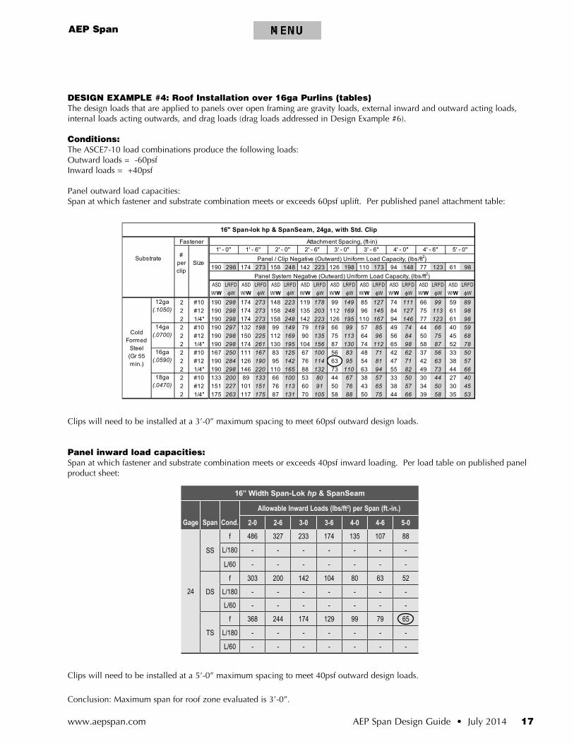
DESIGN EXAMPLE #4: Roof Installation over 16ga Purlins (tables)The design loads that are applied to panels over open framing are gravity loads, external inward and outward acting loads, internal loads acting outwards, and drag loads (drag loads addressed in Design Example #6).
Conditions:The ASCE7-10 load combinations produce the following loads:Outward loads = -60psfInward loads = +40psf
Panel outward load capacities:Span at which fastener and substrate combination meets or exceeds 60psf uplift. Per published panel attachment table:
Clips will need to be installed at a 3’-0” maximum spacing to meet 60psf outward design loads.
Panel inward load capacities:Span at which fastener and substrate combination meets or exceeds 40psf inward loading. Per load table on published panel product sheet:
Clips will need to be installed at a 5’-0” maximum spacing to meet 40psf outward design loads.
Conclusion: Maximum span for roof zone evaluated is 3’-0”.
190 174 158 142 126 110 94 77 61
ASD W/W
ASD W/W
ASD W/W
ASD W/W
ASD W/W
ASD W/W
ASD W/W
ASD W/W
ASD W/W
2 #10 190 174 148 119 99 85 74 66 592 #12 190 174 158 135 112 96 84 75 612 1/4" 190 174 158 142 126 110 94 77 612 #10 190 132 99 79 66 57 49 44 402 #12 190 150 112 90 75 64 56 50 452 1/4" 190 174 130 104 87 74 65 58 522 #10 167 111 83 67 56 48 42 37 332 #12 190 126 95 76 63 54 47 42 382 1/4" 190 146 110 88 73 63 55 49 442 #10 133 89 66 53 44 38 33 30 272 #12 151 101 76 60 50 43 38 34 302 1/4" 175 117 87 70 58 50 44 39 35
LRFD W
Cold Formed
Steel(Gr 55 min.)
12ga (.1050)
14ga (.0700)
16ga (.0590)
18ga (.0470)
298 273 223
98Panel System Negative (Outward) Uniform Load Capacity, (lbs/ft2)
LRFD W
LRFD W
LRFD W
LRFD W
LRFD W
LRFD W
LRFD W
LRFD W
5' - 0"Panel / Clip Negative (Outward) Uniform Load Capacity, (lbs/ft2)
298 273 248 223 198 173 148 123
2' - 0" 2' - 6" 3' - 0" 3' - 6" 4' - 0" 4' - 6"
16" Span-lok hp & SpanSeam, 24ga, with Std. Clip
Substrate
Fastener Attachment Spacing, (ft-in)
# per clip
Size
1' - 0" 1' - 6"
178 149 127 111 99 89
149 119 99
298 273 248 203 169248
59223 195 167
127 113 9814598146
87
85123
74 66298
130 112
297 198
71 5062 56
75298 261 195 156 98298
284 190 142
78250 167 125 100 83
298 220 165 132 110 94
53227
66200 133 100 80 67
263 175 131 105 88 75
84
65151 113 91 7644 40
273
225 169 68135 113 96
50 45
114 95 81 71
58
73
66
82
5757 50
63 57
16” Width Span-Lok hp & SpanSeam
Gage Span Cond.
Allowable Inward Loads (lbs/ft2) per Span (ft.-in.)
2-0 2-6 3-0 3-6 4-0 4-6 5-0
24
SS
f 486 327 233 174 135 107 88
L/180 - - - - - - -
L/60 - - - - - - -
DS
f 303 200 142 104 80 63 52
L/180 - - - - - - -
L/60 - - - - - - -
TS
f 368 244 174 129 99 79 65
L/180 - - - - - - -
L/60 - - - - - - -
www.aepspan.com18 AEP Span Design Guide • July 2014
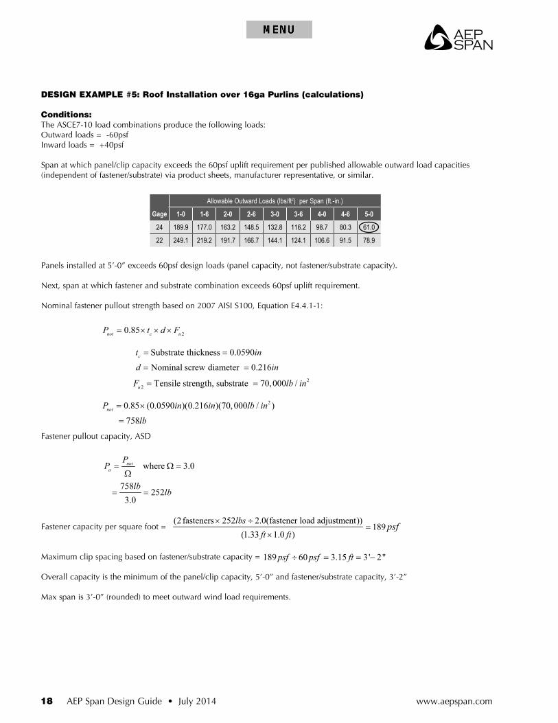
DESIGN EXAMPLE #5: Roof Installation over 16ga Purlins (calculations)
Conditions:The ASCE7-10 load combinations produce the following loads:Outward loads = -60psfInward loads = +40psf
Span at which panel/clip capacity exceeds the 60psf uplift requirement per published allowable outward load capacities (independent of fastener/substrate) via product sheets, manufacturer representative, or similar.
Panels installed at 5’-0” exceeds 60psf design loads (panel capacity, not fastener/substrate capacity).
Next, span at which fastener and substrate combination exceeds 60psf uplift requirement.
Nominal fastener pullout strength based on 2007 AISI S100, Equation E4.4.1-1:
Fastener pullout capacity, ASD
Fastener capacity per square foot =
Maximum clip spacing based on fastener/substrate capacity = 189 60 3.15 3' 2"psf psf ft÷ = = −
Overall capacity is the minimum of the panel/clip capacity, 5’-0” and fastener/substrate capacity, 3’-2”
Max span is 3’-0” (rounded) to meet outward wind load requirements.
where 3.0
758252
3.0
nota
PP
lblb
= Ω =Ω
= =
20.85 (0.0590 )(0.216 )(70,000 / )
758notP in in lb in
lb
= ×
=
22
Substrate thickness 0.0590
Nominal screw diameter 0.216
Tensile strength, substrate 70,000 /
c
u
t in
d in
F lb in
= =
= =
= =
20.85not c uP t d F= × × ×
(2 fasteners 252 2.0(fastener load adjustment))189
(1.33 1.0 )lbs
ft ftpsf× ÷
=×
Gage
Allowable Outward Loads (lbs/ft2) per Span (ft.-in.)
1-0 1-6 2-0 2-6 3-0 3-6 4-0 4-6 5-0
24 189.9 177.0 163.2 148.5 132.8 116.2 98.7 80.3 61.0
22 249.1 219.2 191.7 166.7 144.1 124.1 106.6 91.5 78.9

AEP Span
AEP Span Design Guide • July 2014 19www.aepspan.com
Positive loads:
Check for uniform inward (positive) loads using engineering mechanics:
Inward flexural strength:
Limiting condition for positive loading = negative flexural strength = 308psf
Maximum span based on flexural loading =
DESIGN EXAMPLE #6: Drag Loads over Plywood Substrate
Conditions:Panel: 16in wide Span-lok hp 24gaSubstrate: 19/32” plywoodCombined gravity load: 20psfRoof Slope: 3:12Panel Length: 30ft
Determine Drag Load
2 3
2 2
2 3
2 2
( ) 50000 (0.1132 ) 1655
0.08( ) 0.08(3ft) 12
( ) 50000 (0.0665 ) 1308
0.10( ) 0.10(3ft) 12
b
b
F S lb in in ft ftW psf
L in
F S lb in in ft ftW psf
L in
+
−
+
−
= = =
= = =
2
snow load × panel length × panel width
120 30 16 800
12
snowP
lbs ftft in lbs
ft in
=
= × × =
sin(14 )
0.242 800194
snowDrag P
lbslbs
= ×
= ×
=
6 2 4
4 4
36Deflection Limit, 0.6
60 60( )( )( ) (29.5 10 )(0.1865 )(0.6 in)(12in/ ft)
3418.0069( ) .0069(36 )
lb/ in / ft
L inin
E I x inW
L inpsf
+
∆ = = =
∆= = =
308 40 7 7 7 6psf psf ft÷ = ≈ −. ' "

www.aepspan.com20 AEP Span Design Guide • July 2014
Allowable Fastener Capacities:Substrate lateral (shear) capacity per 2005 NDS Section 11.3.1Nominal capacity is the minimum of the following yield modes:
Mode Im
* NOTE: Since the substrate thickness provides less than the required 6D screw penetration (as specified in NDS Section 11.1.4.6), the substrate will require support blocking at drag fastener locations to meet this minimum penetration requirement.
Mode Is
Mode II
Drag load/Fastener capacity = #fasteners required
2
Diameter (per 11.3.6) 0.171 (Table L3)
Dowel bearing length 19 / 32" 0.593 *
F Member dowel bearing strength 3350 (Table 11.3.2B)
R Reduction term K 10( ) 0.5 (Table 11.3.1B)
= 10(0.171)+0.5 = 2.
r
m
em
d d
D D in
l in
lb in
D
= = =
= = =
= =
= = = +
212(0.171 )(0.593 )(3350 )
153.72.21
in inZ lbs
lb in= =
( )( )m em
d
D l FZ
R= (Eq 11.3-1), where
2
Dowel bearing length 19 / 32" 0.0232 *
F Member dowel bearing strength 65000 (Table 11.3.2B)s
es
l in
lb in
= = =
= =2(0.171 )(0.0232 )(65000 )
116.72.21
in inZ lbs
lb in= =
3350 65000 0.051
0.593 0.0232 25.56e em es
t m s
R F F
R l l
= = =
= = =
' Adjustment Factors (Table 10.3.1)61.8 61.8 1.15 (Table 2.3.2)
71d
Z Zlb C lb
lb
= ×
= × = ×
=
20.53(0.171 )(0.0232 )(65000 )61.8
2.21in in
Z lbslb in
= =
(Eq 11.3-2), where( )( )s es
d
D l FZ
R=
1 ( )( )s es
d
D l FZ
Rk
= (Eq 11.3-3), where
2 2 2 3
1
2 (1 ) (1 )(1 )
e e t t t e e t
e
R R R R R R R Rk
R+ + + + − +
=+
, where
1 0.53k =
194 / (71 ) 2.73 3lb lb fastener fasteners= ≈
AEP Span
AEP Span Design Guide • July 2014 21www.aepspan.com
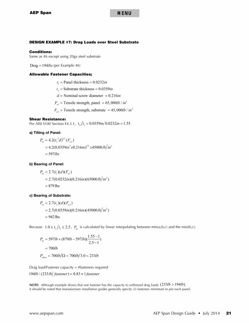
DESIGN EXAMPLE #7: Drag Loads over Steel Substrate
Conditions:Same as #6 except using 20ga steel substrate
Drag 194lbs= (per Example #6)
Allowable Fastener Capacities;
Shear Resistance:Per AISI S100 Section E4.3.1, 2 1 0.0359 0.0232 1.55t t in in= =
a) Tilting of Panel:
b) Bearing of Panel:
c) Bearing of Substrate:
Because 2 11.0 2.5t t≤ ≤ , nsP is calculated by linear interpolating between min(a,b,c) and the min(b,c):
Drag load/Fastener capacity = #fasteners required
NOTE: Although example shows that one fastener has the capacity to withstand drag loads (233 194 )lb lb> , it should be noted that manufacturer installation guides generally specify (3) fasteners minimum to pin each panel.
2
21
22
1 Panel thickness 0.0232
Substrate thickness 0.0359
Nominal screw diameter 0.216
Tensile strength, panel 65,000 /
Tensile strength, substrate 45,000 /u
u
t in
t in
d in
F lb in
F lb in
= =
= =
= =
= =
= =
3 1 22 2
3 1 2 2
4.2( ) ( )
4.2(0.0359 0.216 ) 45000597
ns uP t d F
in x in x lb inlbs
=
=
=
1 1
2
2.7( )( )( )
2.7(0.0232 )(0.216 )(65000 )879 lbs
ns uP t d F
in in lb in
=
=
=
2 2
2
2.7( )( )( )
2.7(0.0359 )(0.216 )(45000 )942 lbs
ns uP t d F
in in lb in
=
=
=
1.55 1597 (879 597 )( )
2.5 1700
nsP lb lb lb
lb
−= + −
−=
700 700 3.0 233allowP lb lb lb= Ω = =
194 / (233 ) 0.83 1lb lb fastener fastener= ≈
www.aepspan.com22 AEP Span Design Guide • July 2014
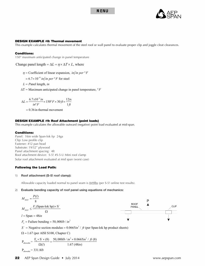
DESIGN EXAMPLE #8: Thermal movementThis example calculates thermal movement of the steel roof or wall panel to evaluate proper clip and joggle cleat clearances.
Conditions:150° maximum anticipated change in panel temperature
Change panel length , whereL T Lη= ∆ = ×∆ ×
66.7 10 12150 30
10.36in thermal movement
x in inL F ft
in F ft
−
∆ = × ° × ×°
=
6
Coefficient of linear expansion,
6.7 10 for steelanel length,
T = Maximum anticipated change in panel temperature,
in in per F
in in per FL P in
F
η−
= °
= × °
=
∆ °
DESIGN EXAMPLE #9: Roof Attachment (point loads)This example calculates the allowable outward (negative) point load evaluated at mid-span.
Conditions:Panel: 16in wide Span-lok hp 24gaClip: Low profile clipFastener: #12 pan headSubstrate: 19/32” plywoodPanel attachment spacing: 4ftRoof attachment device: S-5! #S-5-U Mini roof clampSolar roof attachment evaluated at mid span (worst case)
Following the Load Path:
1) Roof attachment (S-5! roof clamp): Allowable capacity loaded normal to panel seam is 849lbs (per S-5! online test results).
2) Evaluate bending capacity of roof panel using equations of mechanics:
- 2 3b
allowable
allowable
F S (8) 50,000 / 0.0665 / (8)P =
( ) 1.67 (48 )P = 331.8
lb in in ftl in
lb
× × ×=
Ω
2
3
Span 48
Failure bending 50,000 /
Negative section modulus 0.0665 / (per Span-lok hp product sheets)1.67 (per AISI S100, Chapter C)
b
l in
F lb in
S in ft−
= =
= =
= =
Ω =
( )8(Span-lok hp) S
MAX
bMAX
P lM
FM
−
=
×≤
Ω
AEP Span
AEP Span Design Guide • July 2014 23www.aepspan.com
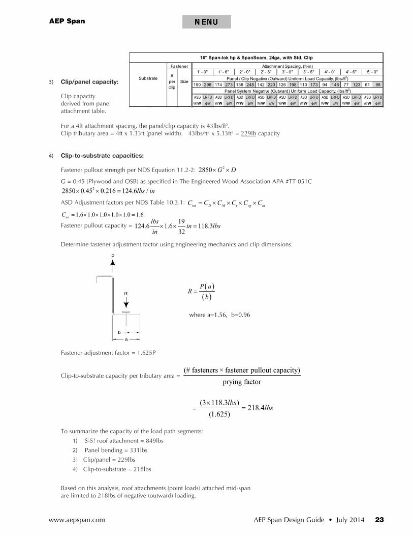
3) Clip/panel capacity:
Clip capacity derived from panel attachment table.
For a 4ft attachment spacing, the panel/clip capacity is 43lbs/ft2. Clip tributary area = 4ft x 1.33ft (panel width). 43lbs/ft2 x 5.33ft2 = 229lb capacity
4) Clip-to-substrate capacities:
Fastener pullout strength per NDS Equation 11.2-2: 22850 G D× ×
G = 0.45 (Plywood and OSB) as specified in The Engineered Wood Association APA #TT-051C22850 0.45 0.216 124.6 /lbs in× × =
ASD Adjustment factors per NDS Table 10.3.1: tot D M t eg tnC C C C C C= × × × ×
1.6 1.0 1.0 1.0 1.0 1.6totC = × × × × =
Fastener pullout capacity = 19
124.6 1.6 118.332
lbsin lbs
in× × =
Determine fastener adjustment factor using engineering mechanics and clip dimensions.
Fastener adjustment factor = 1.625P
Clip-to-substrate capacity per tributary area = (# fasteners × fastener pullout capacity)
prying factor
= (3 118.3 )
218.4(1.625)
lbslbs
×=
To summarize the capacity of the load path segments:
1) S-5! roof attachment = 849lbs
2) Panel bending = 331lbs
3) Clip/panel = 229lbs
4) Clip-to-substrate = 218lbs
Based on this analysis, roof attachments (point loads) attached mid-span are limited to 218lbs of negative (outward) loading.
( )( )
P aR
b=
where a=1.56, b=0.96
190 174 158 142 126 110 94 77 61
ASD W/W
ASD W/W
ASD W/W
ASD W/W
ASD W/W
ASD W/W
ASD W/W
ASD W/W
ASD W/W
2 #10 190 174 148 119 99 85 74 66 592 #12 190 174 158 135 112 96 84 75 612 1/4" 190 174 158 142 126 110 94 77 612 #10 190 132 99 79 66 57 49 44 402 #12 190 150 112 90 75 64 56 50 452 1/4" 190 174 130 104 87 74 65 58 522 #10 167 111 83 67 56 48 42 37 332 #12 190 126 95 76 63 54 47 42 382 1/4" 190 146 110 88 73 63 55 49 442 #10 133 89 66 53 44 38 33 30 272 #12 151 101 76 60 50 43 38 34 302 1/4" 175 117 87 70 58 50 44 39 35
LRFD W
Cold Formed
Steel(Gr 55 min.)
12ga (.1050)
14ga (.0700)
16ga (.0590)
18ga (.0470)
298 273 223
98Panel System Negative (Outward) Uniform Load Capacity, (lbs/ft2)
LRFD W
LRFD W
LRFD W
LRFD W
LRFD W
LRFD W
LRFD W
LRFD W
5' - 0"Panel / Clip Negative (Outward) Uniform Load Capacity, (lbs/ft2)
298 273 248 223 198 173 148 123
2' - 0" 2' - 6" 3' - 0" 3' - 6" 4' - 0" 4' - 6"
16" Span-lok hp & SpanSeam, 24ga, with Std. Clip
Substrate
Fastener Attachment Spacing, (ft-in)
# per clip
Size
1' - 0" 1' - 6"
178 149 127 111 99 89
149 119 99
298 273 248 203 169248
59223 195 167
127 113 9814598146
87
85123
74 66298
130 112
297 198
71 5062 56
75298 261 195 156 98298
284 190 142
78250 167 125 100 83
298 220 165 132 110 94
53227
66200 133 100 80 67
263 175 131 105 88 75
84
65151 113 91 7644 40
273
225 169 68135 113 96
50 45
114 95 81 71
58
73
66
82
5757 50
63 57

MANUFACTURING FACILITIES:
AEP Span10905 Beech AvenueFontana, CA 92337
800-733-4955
AEP Span2141 Milwaukee WayTacoma, WA 98421
253-383-4955800-733-4955
CORPORATE HEADQUARTERS:
ASC Profiles LLC2110 Enterprise Boulevard
West Sacramento, CA 95691800-360-2477
Visit us at:www.aepspan.com
©2014 ASC Profiles LLC All rights reserved. July 2014 2M (BRXXX)
S-5!® is a registered trademark of Metal Roof Innovations, Ltd .AceClamp® is the registered trademark of Innouative Medical products Inc .