Embed Size (px)
Citation preview
Mc
MD
a
ARAA
KCPCPP
1
fc2saLeas2ncpo
ech(r
h0
Computers and Chemical Engineering 95 (2016) 240–248
Contents lists available at ScienceDirect
Computers and Chemical Engineering
j our na l ho me pa g e: www.elsev ier .com/ locate /compchemeng
athematical modeling and optimal design of multi-stage slug-flowrystallization
ichael L. Rasche, Mo Jiang, Richard D. Braatz ∗
epartment of Chemical Engineering, 77 Massachusetts Avenue, Cambridge, MA 02139, United States
r t i c l e i n f o
rticle history:eceived 5 September 2016ccepted 10 September 2016vailable online 28 September 2016
eywords:
a b s t r a c t
Inspired from experimental progress in continuous crystallizer designs based on air/liquid slug flowthat generate crystals of target sizes at high production rates and low capital costs (e.g., Eder et al.,2010; 2011; Jiang et al., 2014; 2015; and citations therein), a mathematical model and procedure arederived for the design of slug-flow crystallizers with spatially varying temperature profiles. The methodof moments is applied to a population balance model for the crystals, to track the spatial variation of
rystallizationharmaceutical engineeringontinuous manufacturingarticulate processesharmaceutical manufacturing
characteristics of the crystal size distribution along the crystallizer length. Design variables for the coolingslug-flow crystallizer such as tubing lengths and types and numbers of heat exchangers are analyzed andoptimized for product crystal quality (e.g., minimized secondary nucleation and impurity incorporation)and experimental equipment costs, while ensuring high yield. This study provides guidance to engineersin the design of slug-flow crystallizers including their associated heat exchanger systems.
© 2016 Elsevier Ltd. All rights reserved.
. Introduction
In the pharmaceutical industry, consistent in-spec productsrom a well-defined robust crystallization process design are cru-ial for both FDA regulation and operational practice (Yu et al.,004; Nagy et al., 2008). Continuous-flow tubular crystallizers havehown potential for high reproducibility and process efficiencyt low capital and production cost (Alvarez and Myerson, 2010;awton et al., 2009; Fergusen et al., 2012; Vacassy et al., 2000; Jiangt al., 2014; Eder et al., 2010, 2011). A technology that combines thedvantages of continuous and batch crystallizers is the air/liquidlug-flow crystallizer (Jiang et al., 2014; Eder et al., 2010, 2011,012; and citations therein), which has advantages that includearrow residence time distribution, no stirrer for inducing parti-le attrition/breakage, and easy post-crystallization separation. Theotential application of slug-flow crystallization in the final stagef pharmaceutical manufacturing motivates this design study.
As in batch crystallizers (e.g., Nagy and Braatz, 2012; Simont al., 2015; and citations therein), the robustness of slug-flowrystallization process operation requires an understanding of
ow the supersaturation profile is affected by design variablese.g., method and speed of supersaturation generation) and cor-esponding implementation. For example, supersaturation should∗ Corresponding author.E-mail address: [email protected] (R.D. Braatz).
ttp://dx.doi.org/10.1016/j.compchemeng.2016.09.010098-1354/© 2016 Elsevier Ltd. All rights reserved.
be minimized so as to avoid impurity incorporation and secondarynucleation, which is important for slug-flow crystallization due toits typically short residence time (on the order of minutes, Ederet al., 2012; Jiang et al., 2014, 2015) and with fast heat transfer (fromthe large surface area to volume ratio of tubular crystallizers).
This article presents a design procedure for slug-flow con-tinuous cooling crystallization with the objective of minimizingthe maximum supersaturation. Two common methods of cool-ing are compared: heat baths and double-pipe heat exchangers(Levenspiel, 1962). The effect of design variables on the supersatu-ration profile is analyzed (e.g., temperatures and locations of heatbaths/exchangers, length of tubing). A population balance modelfor batch crystallization (e.g., Hulburt and Katz, 1964; Randolphand Larson, 1974) is applied to individual slugs, with the batchresidence time replaced by continuous residence time (runningtime). Unlike a past study that mathematical modeled a slug-flowcrystallizer (Kubo et al., 1998), this article considers a different crys-tallization mechanism (cooling crystallization instead of reactiveprecipitation), different crystallization phenomena (growth of indi-vidual crystals instead of aggregation), and not only analyzes ourexperimental proof-of-concept demonstration (Jiang et al., 2014)but also analyzes the effect of the design variables and applies opti-mization (e.g., of the number of heat exchangers and the length oftubing in each heat bath/exchanger) while minimizing the total
equipment cost.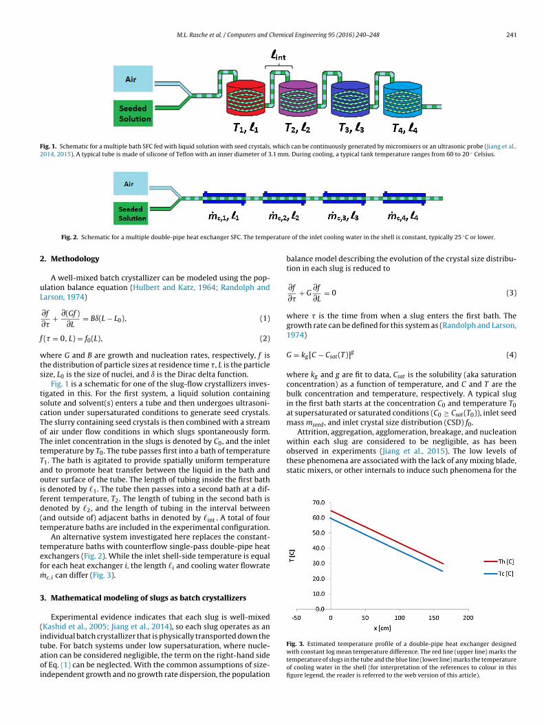
M.L. Rasche et al. / Computers and Chemical Engineering 95 (2016) 240–248 241
Fig. 1. Schematic for a multiple bath SFC fed with liquid solution with seed crystals, which can be continuously generated by micromixers or an ultrasonic probe (Jiang et al.,2014, 2015). A typical tube is made of silicone of Teflon with an inner diameter of 3.1 mm. During cooling, a typical tank temperature ranges from 60 to 20 ◦ Celsius.
eratur
2
uL
f
wts
tscToTtTaoifd(t
tefm
3
(itaoi
observed in experiments (Jiang et al., 2015). The low levels ofthese phenomena are associated with the lack of any mixing blade,static mixers, or other internals to induce such phenomena for the
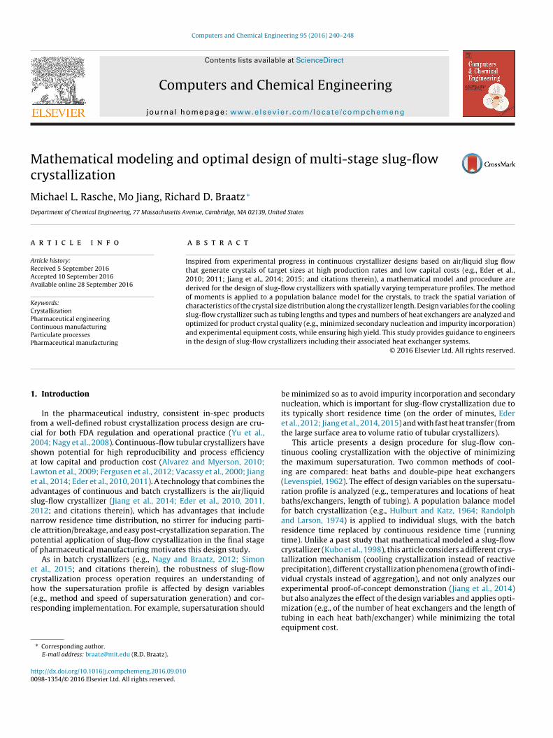
Fig. 2. Schematic for a multiple double-pipe heat exchanger SFC. The temp
. Methodology
A well-mixed batch crystallizer can be modeled using the pop-lation balance equation (Hulbert and Katz, 1964; Randolph andarson, 1974)
∂f
∂�+ ∂(Gf )
∂L= Bı(L − L0), (1)
(� = 0, L) = f0(L), (2)
here G and B are growth and nucleation rates, respectively, f ishe distribution of particle sizes at residence time �, L is the particleize, L0 is the size of nuclei, and ı is the Dirac delta function.
Fig. 1 is a schematic for one of the slug-flow crystallizers inves-igated in this. For the first system, a liquid solution containingolute and solvent(s) enters a tube and then undergoes ultrasoni-ation under supersaturated conditions to generate seed crystals.he slurry containing seed crystals is then combined with a streamf air under flow conditions in which slugs spontaneously form.he inlet concentration in the slugs is denoted by C0, and the inletemperature by T0. The tube passes first into a bath of temperature1. The bath is agitated to provide spatially uniform temperaturend to promote heat transfer between the liquid in the bath anduter surface of the tube. The length of tubing inside the first baths denoted by �1. The tube then passes into a second bath at a dif-erent temperature, T2. The length of tubing in the second bath isenoted by �2, and the length of tubing in the interval betweenand outside of) adjacent baths in denoted by �int . A total of fouremperature baths are included in the experimental configuration.
An alternative system investigated here replaces the constant-emperature baths with counterflow single-pass double-pipe heatxchangers (Fig. 2). While the inlet shell-side temperature is equalor each heat exchanger i, the length �i and cooling water flowrate˙ c,i can differ (Fig. 3).
. Mathematical modeling of slugs as batch crystallizers
Experimental evidence indicates that each slug is well-mixedKashid et al., 2005; Jiang et al., 2014), so each slug operates as anndividual batch crystallizer that is physically transported down the
ube. For batch systems under low supersaturation, where nucle-tion can be considered negligible, the term on the right-hand sidef Eq. (1) can be neglected. With the common assumptions of size-ndependent growth and no growth rate dispersion, the populatione of the inlet cooling water in the shell is constant, typically 25 ◦C or lower.
balance model describing the evolution of the crystal size distribu-tion in each slug is reduced to
∂f
∂�+ G
∂f
∂L= 0 (3)
where � is the time from when a slug enters the first bath. Thegrowth rate can be defined for this system as (Randolph and Larson,1974)
G = kg[C − Csat(T)]g (4)
where kg and g are fit to data, Csat is the solubility (aka saturationconcentration) as a function of temperature, and C and T are thebulk concentration and temperature, respectively. A typical slugin the first bath starts at the concentration C0 and temperature T0at supersaturated or saturated conditions (C0 ≥ Csat(T0)), inlet seedmass mseed, and inlet crystal size distribution (CSD) f0.
Attrition, aggregation, agglomeration, breakage, and nucleationwithin each slug are considered to be negligible, as has been
Fig. 3. Estimated temperature profile of a double-pipe heat exchanger designedwith constant log mean temperature difference. The red line (upper line) marks thetemperature of slugs in the tube and the blue line (lower line) marks the temperatureof cooling water in the shell (for interpretation of the references to colour in thisfigure legend, the reader is referred to the web version of this article).
2 hemic
lo
i1(
�
atttb
wAis
m
T
wacbw
t
T
aba
T
�
c
42 M.L. Rasche et al. / Computers and C
evels of supersaturation that occur in the experiments. The systemf ordinary differential equations
d�0
d�= 0
d�1
d�= G�0
d�2
d�= 2G�1
...
(5)
s obtained by applying the method of moments (Hulburt and Katz,964; Randolph and Larson, 1974) to the population balance model3), where the kth-order moment �k is defined by
k(�) =∫ ∞
0
f (�, L)LkdL (6)
nd the inlet conditions are given by the moments calculated fromhe inlet crystal size distribution f0.1 The zeroth-, first-, second-, andhird-order moments are proportional to the number, total length,otal surface area, and total volume of crystals in a slug. A solutealance for the system is given by
dC
d�= −3G�ckv�2 (7)
here �c is the crystal density and kv is the volumetric shape factor.ssuming that the slug is thermally well-mixed and its heat capac-
ty Cp is spatially uniform, and that the temperature in the bath ispatially uniform, the total mass and energy balances for a slug are
dm
d�= 0, (8)
CpdT
d�= UA(Ti − T) + m�Hc
Mc
dC
d�, (9)
(� = 0) = T0 (10)
here m is the mass of a slug, T is the steady-state temperature as function of residence time�, U is the overall heat transfer coeffi-ient, A is the surface area for heat transfer, Ti is the temperature ofath i, and �Hc and Mc are the heat of crystallization and moleculareight of the solute molecule respectively.
The analytical solution for the energy balance (Eqs. (9)–(10)) inhe first bath is
= T1 + exp
(−UA�
mCp
)[∫ �
0
exp
(UA� ′
mCp
)�Hc
CpMc
dC
d�d� ′ + T0 − T1
]. (11)
Similarly for baths 2–4, assuming temperature does not dropt intervals between adjacent baths (the connection tube betweenaths in well-insulated and the length is minimized), the temper-ture can be calculated as
= Ti + exp
(−UA(� − �i)
mCp
)[∫ �
�i
exp
(UA(� ′ − �i)
mCp
)�Hc
CpMc
dC
d�d� ′ + Ti−1 − Ti
].
(12)
The time for which the slug enters bath i,
i = 1
⎡⎣
⎛⎝ i∑
�i−1
⎞⎠ + �int (i − 1)
⎤⎦ , (13)
vj=1
1 The full crystal size distribution can be constructed from the moments, as dis-ussed in at the end of the Appendix.
al Engineering 95 (2016) 240–248
is calculated by assuming a constant velocity v. The overall heattransfer coefficient U is composed of three parts: convective heattransfer within the slug surface, conduction through the tube wall,and convective transfer in the bulk cooling water (bath), that is,
1U
= 1hslug
+d1 ln d2
d1
2kw+ 1
hbath. (14)
where d1 and d2 are the inside and outside diameters of the tubing,kw is the thermal conductivity of the tube wall, and hslug and hbathare respective convective heat transfer coefficients. The Sieder-Tatecorrelation for the Nusselt number (Sieder and Tate, 1936),
Nu = hslugd1
ks= 0.023Re0.8Pr1/3
(�c,s
�w,s
), (15)
can be used to determine hslug, where Re and Pr are the Reynoldsand Prandtl numbers, respectively, ks is the thermal conductivityof the slug solution, and the ratio of dynamic viscosities in the lastterm for the slug solution at the center and wall is assumed tobe unity. The value for hbathcan be calculated from (Chilton et al.,1944),
Nu = hbathD
kb= 0.87Re2/3
N Pr1/3
(�c,b
�w,b
)0.14
, (16)
where D is the inside diameter of the agitated vessel, kb is the ther-mal conductivity of the bath fluid (typically water), the last term isthe ratio of dynamic viscosities for the bath fluid, and the Reynoldsnumber ReN for an agitated vessel is given by
ReN = N�bL2a
�c,b, (17)
where N is the agitator speed, La is the agitator diameter, and �b
and �c,b are the density and dynamic viscosity of the bath fluid.For the multi-bath system, an optimal choice for the bath
temperatures and tube lengths is based on the objective of lowmaximum supersaturation level within the metastable zone, tomaintain purity and avoid secondary nucleation within the liquidslugs passing through the tube. In the case of the four-bath system,the optimization is given by
minT1, T2, T3
�1, �2, �3, �4
w1 max{
0, [Cf − Csat(T4)]}
+ w2Smax + w3
∑i
�i
(18)
where the first term compares the final concentration Cf in thesystem to Csat(T4), the saturation concentration at the final temper-ature, to force high yield. In the second term, Smax is the maximumsupersaturation within the system. The third term is the total lengthof tubing.
The outlet temperatures of a double-pipe heat exchanger canbe calculated using the effectiveness defined as (Kays and London,1984)
� = 1 − e−˛
1 − WcWs
e−˛, (19)
for Wc /= Ws, where Ws and Wc are the heat capacity rates of slugsand cooling water (W = mCp), and the exponent is defined by
= Ud1�ˇ(
1Wc
− 1Ws
)(20)
where U is the overall heat transfer coefficient, d1 is the tube diam-
eter and � is the length of the tube. Then the outlet temperature ofthe slug stream isTs,out = Ts,in + Wc
Ws�(
Tc,in − Ts,in
)(21)
hemical Engineering 95 (2016) 240–248 243
wst
W
lo(
T
tta
ws
4
TTt
C
4
peoT2c
strpabsteskm
ktgt
Table 1Model parameters used in the simulation study. The crystallization kinetic param-eters in rows 1 and 2 are for l-asparagine monohydrate (LAM) in aqueous solutionfrom Jiang et al. (2012), the crystallizer equipment parameters are for the experi-mental slug-flow crystallizer implemented by Jiang et al. (2014), and the thermalconductivity is for silicone rubber (Incropera and DeWitt, 2002). The values of theweights w1to w3 were selected using an iterative approach, where the optimalparameters for given weights were input to the simulation and results were visuallyinspected.
Variable Value Units
kg 6.353 (�m-g solution)/(s-g LAM)g 1.0 unitlessˇ 0.25 unitless
�Hc −35700 J/mol�b,c 0.001 Pa-s�b,w 0.001 Pa-s
�s,c/�s,w 1 unitless�b 1000 kg/m3
�c 1543 kg/m3
Aa �(0.0031)(0.003) m3
C0 0.16 g LAM/g solutionCb
p,c 4187 J/(kg-K)Cb
p,h4187 J/(kg-K)
d1 0.0031 md2 0.006 mD 0.15 mkb 0.597 W/(m-K)ks 0.597 W/(m-K)kv 1.0 dimensionlesskw 0.14 W/(m-K)La 0.06 m
mseed 2.86×10⁻⁹ gmsolvent 2.12×10⁻² g
mch
4.24×10⁻² g/sMc 0.150 kg/molN 1 1/sT0 64.6 ◦C
Tc,in 20.0 ◦Cw1 5 × 10³ g solution/g LAMw2 5 × 10³ g solution/g LAMw3 0.1 1/m
a The slug-wall contact area A assumes a slug with contact that is 3 mm long with atube that has inner diameter of 3.1 mm. The slug length is selected to be about equalto the inner diameter so as to maximize the mixing in each slug, as shown in imagesof Jiang et al. (2014).bThe heat capacities of the cold and hot streams are approximated as the heat capac-ity of water.cThe slug mass of 2.12 × 10⁻²g multiplied by the slug flowrate of 2 slugs per second.
Table 2Comparison of contributions to the overall heat transfer coefficienta for a four-tank SFC case study with model parameters taken from experiments. The tube wallprovides the largest resistance to heat transfer.
hslug hbwall
hbath U
327 137 1560 96.4
a W
M.L. Rasche et al. / Computers and C
here the inlet temperatures Tc,in and Ts,in of the cooling water andlug stream, respectively, are specified. For Wc = Ws, the applica-ion of L’Hopital’s rule to (25) gives the expression
limc→Ws
� = Ud1�ˇ
Ud1� + Ws. (22)
If curvature caused by the non-constant �TLM is neglected, ainear approximation to the temperature in the tube as a functionf distance x from the heat exchanger entrance can be derived asjustification given in Supplementary material)
s(x) = Ts,in − Ts,out − Ts,in
�x. (23)
For a given inlet temperature of cooling water and total length ofubing, the lengths of tubing in each heat exchanger can be choseno minimize the supersaturation over the total length of tube whilelso maximizing the total yield:
min�1, �2, �3
mc,1, mc,2, mc,3, mc,4
[Smax + ε1 max
{Cf − Csat(Tc,in), 0
}]
0 < �i ≤ �total, i = 1, . . ., n
�n = �total −n−1∑
i
�i
0 < mc,i ≤ mc,max, i = 1, . . ., n.
(24)
here the value of ε1 specifies the tradeoff between maximumupersaturation and yield in a system with fixed tube length.
. Results and discussion
The parameters used in this simulation study are reported inable 1, with the resulting heat transfer terms in Eq. (14) given inable 2. The analytical expression for the solubility as a function ofemperature used in this article is taken from Jiang et al. (2012):
sat = 3.084 × 10⁻² − 1.373 × 10⁻³T + 5.214 × 10⁻⁵T2. (25)
.1. Constant-temperature baths
For the multi-bath system described above, the optimal designarameters determined by numerical solution of Eq. (18) for lit-rature values of the growth kinetics are reported in the first rowf Table 3, with the associated simulation outputs shown in Fig. 4.able 3 also reports optimal design parameters corresponding to0% relative error in the growth kinetic parameters, with the asso-iated simulation results in Fig. 4 as well.
All of the optimal designs in Fig. 4 have four peaks of super-aturation with roughly equal height, as determined by the bathemperature, except for the case of increased g, in which the cor-esponding decrease in growth rate is so high that only the firsteak occurs for the fixed residence time. The optimal lengthsllow the supersaturation to approach zero before entering a newath. Increasing g or decreasing kg slows the growth kinetics ando increases the length of tubing (and residence time) neededo achieve the desired yield (Table 3). The value of the growthxponent g has a large effect on the growth kinetics, and corre-pondingly, the length of tubing required. Variation in the growthinetics has a comparatively small effect on the values of the opti-al bath temperatures and the maximum supersaturation.Alternatively, Table 4 shows the effect of 20% error in the growth
inetic parameters if not taken into account in the design calcula-ions. To construct this table, the length and temperature valuesiven by the first row of Table 3 are used in the SFC design, buthe values of the growth kinetic parameters are altered as shown
numerical values given in SI units:m2K
.
bthermal conductance of the wall: hwall = 2kw
(d1 ln d2
d1
)−1.
to demonstrate the robustness of the nominal process design touncertainties in the growth kinetics. Fig. 5 shows the simulationresults corresponding to the rows of Table 3.
When the true growth kinetics are faster than assumed in theprocess design calculations, the lengths corresponding to the orig-inal growth rate are more than sufficient, so a slight improvementis seen in the yield, and the maximum supersaturation remainsunaffected (Table 4). When the true growth rate is 20% slower (lastrow in Table 4), there is a modest decrease in yield and increase in
the maximum supersaturation. When the true growth kinetics aremuch slower than used in the design calculations (g + 20%), the yieldis much lower and the peak supersaturation is much higher, whichwould result in lower molecular purity of the product crystals. If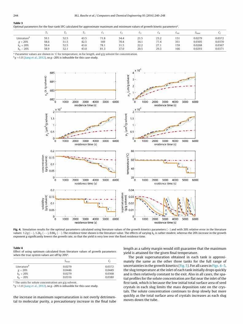
244 M.L. Rasche et al. / Computers and Chemical Engineering 95 (2016) 240–248
Table 3Optimal parameters for the four-tank SFC calculated for approximate maximum and minimum values of growth kinetic parametersa.
T1 T2 T3 �1 �2 �3 �4 �tot Smax Cf
Literatureb 59.1 52.5 43.5 71.8 34.4 21.5 23.2 151 0.0279 0.0372g + 20% 58.6 51.5 42.5 169 70.4 34.1 77.4 351 0.0305 0.0370kg + 20% 59.4 52.5 43.6 78.1 31.5 22.2 27.1 159 0.0268 0.0367kg − 20% 58.9 52.1 43.0 81.3 37.0 20.5 29.3 166 0.0293 0.0371
a Parameter values are shown in ◦C for temperature, m for length, and g/g solvent for concentration.bg ≈1.0 (Jiang et al., 2012), so g−20% is infeasible for this case study.
Fig. 4. Simulation results for the optimal parameters calculated using literature values of the growth kinetics parameters (−) and with 20% relative error in the literaturevalues: 1.2 g (−·), 1.2kg (−−), 0.8kg (· · ·). The residence time shown is the literature value.exponent g significantly lowers the growth rate, so that the yield is very low over the fixe
Table 4Effect of using optimum calculated from literature values of growth parameterswhen the true system values are off by 20%a.
Smax Cf
Literatureb 0.0279 0.0372g + 20% 0.0446 0.0449kg + 20% 0.0279 0.0368kg − 20% 0.0316 0.0380
a
b
tt
crystals in each slug limits the mass deposition rate on the crys-
The units for solute concentration are g/g solvent.g ≈1.0 (Jiang et al., 2012), so g−20% is infeasible for this case study.he increase in maximum supersaturation is not overly detrimen-al to molecular purity, a precautionary increase in the final tube
The effects of varying kg is rather modest, whereas the 20% increase in the growthd residence time.
length as a safety margin would still guarantee that the maximumyield is attained for the given final temperature.
The peak supersaturation obtained in each tank is approxi-mately the same as the other three tanks for the full range ofuncertainties in the growth kinetics (Fig. 5). For all cases in Figs. 4–5,the slug temperature at the inlet of each tank initially drops quicklyand is then relatively constant to the exit. Also in all cases, the spa-tial profiles for the solute concentration are flat near the inlet of thefirst tank, which is because the low initial total surface area of seed
tals. The solute concentration continues to drop slowly but morequickly as the total surface area of crystals increases as each slugmoves down the tube.

M.L. Rasche et al. / Computers and Chemical Engineering 95 (2016) 240–248 245
F parameters using the optimal operating conditions predicted by literature values (−) butt decreased growth rate results in higher supersaturation peaks and lower yield, while ani
4
eatcttitcethtf
pumtTf
Fig. 6. The objective function for the double-pipe SFC (Eq. (24)) is plotted for a single
ig. 5. Simulation results showing the effects of uncertainty in the growth kinetics
hen introducing a 20% error in the parameters: 1.2 g (−·), 1.2kg (−−), 0.8kg (· · ·). A
ncreased growth rate increases yield.
.2. Double-pipe heat exchangers
For double-pipe heat exchangers in series, for each heatxchanger, the optimum occurs when the length of the tubepproaches infinity, and the cooling water flowrate is high enougho remove all of the excess heat from the system (Fig. 6). Theseonditions cause the peak supersaturation to approach zero whilehe yield approaches its maximum value. In a practical system, theotal tube length are cooling water flowrates are finite. If the cool-ng water flowrate is given a maximum value of 50 mg/s and theotal length of tubing is restricted to 300 m, the Pareto-optimalityurve in Fig. 7 can be constructed from the data in Table 5 for n heatxchangers in series. Fig. 7 demonstrates the tradeoff between thewo objectives as well as the diminishing returns of adding moreeat exchangers beyond n = 3. The simulation results around theradeoff point (the leftmost non-trivial solution) are shown in Fig. 8or each value of n.
Fig. 8 shows an increase in the number of supersaturationeaks as the number of heat exchangers increase, with the val-es of supersaturation in this system lower than predicted by the
ulti-bath system by a factor of three, due to the improved spa-ial temperature profiles obtained by counterflow heat exchange.he solute concentration near the inlet of the first tank is very flator a significant slug residence time in the tube, and the smoother
heat exchanger (n = 1), when total length and cooling water flowrate take on a largerange of values.
reduction in temperature results in a smoother reduction in sol-ubility, and a smoother increase in the supersaturation. Once the

246 M.L. Rasche et al. / Computers and Chemical Engineering 95 (2016) 240–248
Table 5Optimal parameters for the double-pipe SFC for different values of ε1 in Eq. (24) and different numbers of heat exchangers, n. The range of values (in meters) for the lengthsis [0,300] and the range for the cooling water flowrate (in mg/s) is [0.001,50]. The below data are used to construct the Pareto-optimality curve (Fig. 7).
n ε1 �1 �2 �3 �4 mc,1 mc,2 mc,3 mc,4
1 0.01 300 0.0010.1 300 0.001
0.18 300 0.0010.19 300 340.2 300 35
0.25 300 400.5 300 501 300 50
2 0.01 170 130 0.001 0.0010.1 156 144 6 431 146 154 6 50
10 110 190 5 49100 273 27 50 27
3 0.01 300 0 0 0.001 0.001 0.0010.1 153 96 51 4.3 17 490.5 161 130 9 6.9 49 1.41 154 136 10 6.6 50 3.9
10 144 134 22 7 50 48100 273 12 15 50 48 46
4 0.001 300 0 0 0 0.001 0.001 0.001 0.0010.01 119 53.4 62.4 65.2 2.91 4.28 13.3 500.1 119 58.4 57.6
1 139 73 75
10 138 75 62
Fig. 7. Pareto-optimality curves for the double-pipe SFC with different total numberof heat exchangers at a constant total tube length of 300 m, with data reported inToh
sd(cbysmidk
5
t
able 5. Each point on a Pareto-optimality curve is optimal for a partial weightingf the two competing objectives. Given the economic incentive is high to maintainigh yield, the most practical optimum would be near the “knee” of each curve.
upersaturation reaches its peak, it does not drop as low for theouble-pipe heat exchangers as for the constant-temperature bathscf Figs. 4–5 with Fig. 8)—the maintenance of a persistent signifi-antly positive supersaturation enables the peak supersaturation toe lower for the double-pipe exchangers while achieving the sameield as the constant-temperature baths. Note that the yield in anyystem of heat exchangers is theoretically restricted by the mini-um system temperature given that a sufficient length of tubing
s available, so installing extra tubing is a way to ensure that theesired yield is obtained. The larger the uncertainty in the growthinetics, the larger the extra tubing should be.
. Conclusions
Mathematical models and design procedures are proposed forwo continuous slug-flow crystallization systems. By combining
65.0 2.91 4.71 13.2 5013 12 49 15 5025 4 14 50 49
constant-temperature cooling baths in series, the temperature ofthe slugs is stepped down gradually to maintain low supersatura-tion, to promote growth over nucleation, while allowing high yield.The advantage of simplicity is offset by relatively high spikes insupersaturation at the inlet to each bath. An alternative systemis investigated that uses multiple counterflow double-pipe heatexchangers in series to reduce the temperature more gradually.The double-pipe heat exchange system provides similar high yield,while reducing the maximum supersaturation by a factor of threein a case study using realistic experimental values for the parame-ters. In the case study, it was observed that increasing the numberof heat exchangers beyond three had only a small effect on theoptimal design objective and tradeoff curve (Fig. 7). For either heatexchanger design, an extra length of tubing can be used to ensurethat the desired yield is achieved for a specified uncertainty ingrowth kinetics (Fig. 6).
Acknowledgement
Novartis is acknowledged for support of this work.
Appendix A.
The inlet initial crystal size distribution in the simulation studyis given by a quadratic function (e.g., Chung et al., 2000; Togkalidouet al., 2004)
f0(L) ={
aL2 + bL + c, forLmin ≤ L ≤ Lmax
0, otherwise(A1)
The CSD is assumed symmetrical with the peak at L = 5 �manddistribution width w = 2 �m, which are estimated based on opti-cal microscopy measurement. Eq. (A1) is equal to zero at L = L ±w/2, so that
Lmin = L − w
2, (A2)
Lmax = L + w
2. (A3)

M.L. Rasche et al. / Computers and Chemical Engineering 95 (2016) 240–248 247
F ·),n =
t offer
a
(
a
a
wbv
sa
f
ti∫t
ig. 8. Simulation results for the double-pipe SFC near the tradeoff point for n = 1(−he maximum supersaturation by about a factor of two. Additional heat exchangers
The parameters a, b, and c in Eq. (A1) can be determined bynalytically solving the system of linear equations
L6max − L6
min)a
6+ (L5
max − L5min)
b
5+ (L4
max − L4min)
c
4= mseed
msolvent�c, (A4)
L2max + bLmax + c = 0, (A5)
L2min + bLmin + c = 0. (A6)
here the first equation is obtained by integrating L3 multipliedy (A1) to determine the crystal mass per mass solvent, and theolume shape factor is assumed to be equal to one.
While this article uses moments to describe the evolution of theize distribution, the system (3)–(4) with initial condition (A1) isn example of the 1D advection equation with solution given by
(�, L) = f0
(L −
∫ �
0
Gd� ′)
, (A7)
that is, the solution to the PBE is a translation of the initial dis-ribution. Recognizing that the integral in (A7) can be calculated byntegrating the second differential equation of (5),
�
0
Gd� ′ = �1(�) − �1(0)�0
, (A8)
he crystal size distribution can be constructed.
2 (−−),n = 3(· · ·), and n = 4(−). Using two heat exchangers instead of one decreases an ever-diminishing return on investment.
Appendix B. Supplementary data
Supplementary data associated with this article can be found,in the online version, at http://dx.doi.org/10.1016/j.compchemeng.2016.09.010.
References
Alvarez, A.J., Myerson, A.S., 2010. Continuous plug flow crystallization ofpharmaceutical compounds. Cryst. Growth Des. 56, 349–369.
Chilton, T.H., Drew, T.B., Jenkins, R.H., 1944. Heat transfer coefficients in agitatedvessels. Ind. Eng. Chem. 36 (6), 510–516.
Chung, S.H., Ma, D.L., Braatz, R.D., 2000. Optimal experimental design in batchcrystallization. Chemom. Intell. Lab. Syst. 50, 83–90.
Eder, R.J.P., Radl, S., Schmitt, E., Innerhofer, S., Maier, M., Gruber-Woelfler, H.,Khinast, J.G., 2010. Continuously seeded continuously operated tubularcrystallizer for the production of active pharmaceutical ingredients. Cryst.Growth Des. 10 (5), 2247–2257.
Eder, R.J.P., Schmitt, E.K., Grill, J., Radl, S., Gruber-Woelfler, H., Khinast, J.G., 2011.Seed loading effects on the mean crystal size of acetylsalicylic acid in acontinuous-flow crystallization device. Cryst. Res. Technol. 46 (3), 227–237.
Eder, R.J.P., Schrank, S., Besenhard, O., Roblegg, E., Gruber-Woelfler, H., Khinast,J.G., 2012. Continuous sonocrystallization of acetylsalicylic acid (ASA): controlof crystal size. Cryst. Growth Des. 12 (10), 4733–4738.
Ferguson, S., Morris, G., Hao, H., Barrett, M., Glennon, B., 2012. In-situ monitoringand characterization of plug flow crystallizers. 18th International Symposiumon Industrial Crystallization 77, 105–111.
Hulburt, H.M., Katz, S., 1964. Some problems in particle technology. A statisticalmechanical formulation. Chem. Eng. Sci. 19 (8), 555–574.
2 hemic
I
J
J
J
K
K
K
L
L
N
48 M.L. Rasche et al. / Computers and C
ncropera, F.P., DeWitt, D.P., 2002. Fundamentals of Heat and Mass Transfer, 5th ed.Wiley, Hoboken, NJ.
iang, M., Wong, M.H., Zhu, Z., Zhang, J., Zhou, L., Wang, K., Ford Versypt, A.N., Si, T.,Hasenberg, L.M., Li, Y.E., Braatz, R.D., 2012. Towards achieving a flattop crystalsize distribution by continuous seeding and controlled growth. Chem. Eng. Sci.77, 2–9.
iang, M., Zhu, Z., Jimenez, E., Papageorgiou, C.D., Waetzig, J., Hardy, A., Langston,M., Braatz, R.D., 2014. Continuous-flow tubular crystallization in slugsspontaneously induced by hydrodynamics. Cryst. Growth Des. 14 (2), 851–860.
iang, M., Papageorgiou, C.D., Waetzig, J., Hardy, A., Langston, M., Braatz, R.D., 2015.Indirect ultrasonication in continuous slug-flow crystallization. Cryst. GrowthDes. 15 (5), 2486–2492.
ashid, M.N., Gerlach, L., Goetz, S., Franzke, J., Acker, J.F., Platte, F., Agar, D.W.,Turek, S., 2005. Internal circulation within the liquid slugs of a liquid–liquidslug flow capillary microreactor. Ind. Eng. Chem. Res. 44 (14), 5003–5010.
ays, W.M., London, A.L., 1984. Compact Heat Exchangers, 3rd ed. McGraw-Hill,New York.
ubo, M., Kawakatsu, T., Yonemoto, T., 1998. Modelling of continuous synthesisprocess of TiO2 particles using slug-flow tubular reactor. Chem. Eng. Res. Des.76 (6), 669–676.
awton, S., Steele, G., Shering, P., Zhao, L., Laird, I., Ni, X.-Y., 2009. Continuouscrystallization of pharmaceuticals using a continuous oscillatory baffled
crystallizer. Org. Process Res. Dev. 13 (6), 1357–1363.evenspiel, O., 1962. Chemical Reaction Engineering: An Introduction to the Designof Chemical Reactors. Wiley, New York.
agy, Z.K., Braatz, R.D., 2012. Advances and new directions in crystallizationcontrol. Annu. Rev. Chem. Biomol. Eng. 3, 55–75.
al Engineering 95 (2016) 240–248
Nagy, Z.K., Fujiwara, M., Braatz, R.D., 2008. Modeling and control of combinedcooling and antisolvent crystallization processes. J. Process Control 18,856–864.
Randolph, A.D., Larson, M.A., 1974. Theory of Particulate Processes: Analysis andTechniques of Continuous Crystallization, volume 2nd. Academic Press, NewYork.
Sieder, E.N., Tate, G.E., 1936. Heat transfer and pressure drop of liquid in tubes. Ind.Eng. Chem. 28 (12), 1429–1435.
Simon, L.L., Pataki, H., Marosi, G., Meemken, F., Hungerbühler, K., Baiker, A.,Tummala, S., Glennon, B., Kuentz, M., Steele, G., Kramer, H.J.M., Rydzak, J.W.,Chen, Z., Morris, J., Kjell, F., Singh, R., Gani, R., Gernaey, K.V., Louhi-Kultanen,M., O’Reilly, J., Sandler, N., Antikainen, O., Yliruusi, J., Frohberg, P., Ulrich, J.,Braatz, R.D., Leyssens, T., von Stosch, M., Oliveira, R., Tan, R.B.H., Wu, H., Khan,M., O’Grady, D., Pandey, A., Westra, R., Delle-Case, E., Pape, D., Angelosante, D.,Maret, Y., Steiger, O., Lenner, M., Abbou-Oucherif, K., Nagy, Z.K., Litster, J.D.,Kamaraju, V.K., Chiu, M.-S., 2015. Assessment of recent process analyticaltechnology (PAT) trends: a multiauthor review. Org. Process Res. Dev. 19, 3–62.
Togkalidou, T., Tung, H.-H., Sun, Y., Andrews, A., Braatz, R.D., 2004. Parameterestimation and optimization of a loosely-bound aggregating pharmaceuticalcrystallization using in-situ infrared and laser backscattering measurements.Ind. Eng. Chem. Res. 43, 6168–6181.
Vacassy, R., Lemaitre, J., Hofmann, H., Gerlings, J.H., 2000. Calcium carbonate
precipitation using new segmented flow tubular reactor. AIChE J. 46 (6),1241–1252.Yu, L.X., Lionberger, R.A., Raw, A.S., D’Costa, R., Wu, H., Hussain, A.S., 2004.Applications of process analytical technology to crystallization processes. Adv.Drug Deliv. Rev. 56, 349–369.