Embed Size (px)
Citation preview

Computer ScienceTechnical Report
Simulating a General Purpose MobileComputing Environment�
Anurag Kahol, Sumit Khurana, Sandeep Gupta and Pradip SrimaniDepartment of Computer Science
Colorado State UniversityFt. Collins, CO 80523
July 9, 1998
Technical Report CS-98-110
Computer Science DepartmentColorado State University
Fort Collins, CO 80523-1873
Phone: (970) 491-5792 Fax: (970) 491-2466WWW: http://www.cs.colostate.edu
�Address for Correspondence: Pradip K Srimani, Department of Computer Science, Colorado State University, Ft.Collins, CO 80523, Voice: (970) 491-7097, Email: [email protected]
Simulating a General Purpose Mobile ComputingEnvironment�
Anurag Kahol, Sumit Khurana, Sandeep Gupta and Pradip SrimaniDepartment of Computer Science
Colorado State UniversityFt. Collins, CO 80523
July 9, 1998
Abstract
This paper reports the modeling and implementation of a general purpose mobile comput-ing environment. The design is modular and it incorporates all intrinsic operations of mobilecomputing, using the working of a mobile telephony system as a basis. The SES/Workbenchhas been used as the primary tool for implementation; oneof the purposes was to investigatethe usefulness of the tool to simulate a scalable and flexible mobile computing testbed. Modelsand submodels have been described and the correctness and the scalability of the design havebeen demonstrated by presenting experimental results of simulating a fixed channel assignmentscheme. computing environment. The simulation has been designed in a modular fashion in-corporating all the intrinsic operations of mobile computing, taking the working of a mobiletelephony system as a basis. To demonstrate the correctness, scalability and flexibility of oursimulation model we present results for a fixed channel assignment scheme.
1 Introduction
Mobile computing is a distributed computing paradigm where users are free to move about without
losing the ability to connect to a network. This poses several interesting problems which are dif-
ferent from those in a static network. Routing a connection to a mobile host involves determining
�Address for Correspondence: Pradip K Srimani, Department of Computer Science, Colorado State University, Ft.Collins, CO 80523, Voice: (970) 491-7097, Email: [email protected]
1

its location. Communication takes place over wireless channels. Wireless channels are character-
ized by low bandwidths and are less reliable than their static counterparts due to their susceptibility
to interference and fading. There is a need to have channel allocation schemes that mitigate these
effects[Jor95]. Mobile hosts are relatively underprivileged compared to nodes on a static network
in terms of computational power and network connectivity. Innovations are required to reduce the
computational requirements by shifting some of the computational load to static hosts. Caching
schemes to lower the reliance on the network connectivity also need to be looked into. Hence there
is a need for a comprehensive testbed to study the effects of mobility and determine the effective-
ness of all such proposed schemes.In this project we have developed a modular simulation envi-
ronment for mobile computing. To develop the simulation we used SES/Workbench, which is an
event driven simulation tool [Sci94a] [Sci94b]. Our simulation model is flexible, allowing us to
easily simulate proposed solutions to various mobile computing problems. It is scalable in that it
can simulate networks of different sizes with different parameters.
The rest of this paper is organized as follows. In the next section we explain the system model used
in our mobile computing environment. Section 3 explains the high level protocol that we used for
connection setup and mobility. Section 4 gives a brief explanation of the various modules that make
up our simulation. Each of these have a corresponding implementation in SES/Workbench. Section
6 presents an example simulation to illustrate the current status of the simulator and finally section
7 gives conclusions and the enhancements that still need to be made to the simulator.
2 System Model
A mobile system consists of the following entities
� Cell A geographical area consisting of a Mobile Support Station(MSS) and a dynamic set of
Mobile Hosts(MHs) communicating with the mobile support station. A cell is characterized
by it’s geographical area, the MSS that caters to the MHs in this area and a set of wireless
channels that are used by the MSS to communicate with these MHs. Two neighboring cells
2

may not be able to use the same set of wireless frequencies as they might interfere with com-
munications in an adjoining cell.
� Mobile Host (MH) A user’s portable device e.g. a laptop computer, a cell phone, that enables
him to connect to the network.
� Mobile Support Station (MSS) A node on the static network which provides an interface to
the static network for each MH in it’s cell. Communication requests by the MH are routed
to the MSS via a wireless link. The MSS is responsible for routing the request on the wired
network and sending the result of the request back to the MH.
3 Protocol
Figure 1: Call Module
3.1 Call Setup
� MH initiating a call sends an RTS(Request To Send) to its MSS
� MSS allocates a channel to the MH (Channel Allocation)if its available, otherwise sends back
an REJ(REJect).
� After allocating a channel, MSS locates the present position of the callee MH (Location Man-
agement) and sends an RTS to the callee’s MSS.
3

� The callee’s MSS allocates a channel for the call, if available. If not , it routes an REJ back
to the caller MH via the caller’s MSS.
� After allocating a channel, the callee MSS sends an RTS to the callee MH.
� The callee MH responds with a CTS (Clear To Send) and routes it back to the caller MH,
retracing the path of the RTS.
� The connection is setup once the CTS reaches the caller MH. Both parties can now send data.
� Either party can stop the communication by sending a disconnect message and channels are
freed at both ends.
3.2 Handoff / Call maintenance
Figure 2: Mobility Module
� MH moving from one MSS to the other (MHmover moving from MSSsource to MSSdest)
sends a greeting message toMSSdest.
� If a call is in progress,MSSdest allocates a channel for this call, if no channel is available, a
disconnect message is sent to both caller and callee MHs.
� MSSdest sends a deregister message toMSSsource.
4

� On receiving the deregister message,MSSsource removesMHmover from it’s list of MHs in
its cell and sends back a register message toMSSdest. If a call forMHmover is in progress,
a call maintenance message to the correspondent MSS.
� On receiving the register message,MSSdest addsMHmover to the list of MHs in its cell. This
concludes the Handoff process.
� On receiving a call maintenance message the correspondent MSS updates the location infor-
mation forMHmover fromMSSsource toMSSdest.
4 Simulation Modules
Figure 3: System Modules
The model comprises of two independent main modules - the first models mobility of users and the
second refers to call generation and transmission. A population initialization module defines the
initial state of the above modules.
5

4.1 Populate
This submodule generates the initial population of Mobile Hosts(MH) in the system. MHs belong-
ing to various categories depending upon their mobility and calling patterns can enter the system.
4.2 Mobility Model
This submodule simulates the moves MHs make within the system. Each MH leaves it’s present
position with a certain probability and updates it’s current location w.r.t. an MSS i.e. a mapping of
MH to MSS is maintained.
4.3 Call Model
This is the module responsible for generating calls. It captures the calling behavior of each MH by
assigning a distribution to the number of calls made by it.
4.4 Wireless
Wireless module simulates the wireless communication channel between an MH and an MSS. Mes-
sages generated by the traffic module of the MH are transmitted through the wireless channel to the
MSS. Each call is given a dedicated channel at each of the two MSSs.
4.5 Mobile Service Station (MSS)
The MSS handles all communication of the MH by executing the message passing protocols de-
scribed in the previous section. The MSS also has two sub-modules responsible for channel allo-
cation and location management.
6

� Channel Allocation
When an MH wishes to communicate, a request is sent for channel assignment. The channel
allocation module handles this request by assigning a certain free channel to the requesting
MH. If a channel is not available, then the connection request by the MH is rejected.
� Location Management
After a channel has been allocated, a request is sent to determine the location of the recipient
of the call. The Location Management module handles this request by running an algorithm
to identify the MSS where the callee is residing and communicates this information back to
the caller. these steps, the MSS routes messages to the destination through the topology.
4.6 Mobile Host (MH)
This module models the behavior of a MH in the system. Each MH is characterized by a certain
calling and mobility behavior. An MH generates calls in the system according to its calling char-
acteristic and this functionality is handled by the traffic sub-module.
� Traffic
Once a call has been established, the traffic modules at each of the correspondent MHs take
over and are responsible for sending data. Characteristics of the generated traffic are deter-
mined by the type of call being executed and this information is passed down by the caller
module.
4.7 Topology
This module simulates the wired network of all MSSs in the system. Messages are routed from one
MSS to another, dependent on the topology.
7

5 SES Implementation
Each of the modules enumerated above is implemented as a submodel in SES. SES uses an ob-
ject oriented approach,defining a set of nodes and transactions to model system behavior.Different
nodes have different functionality e.g. a blocking node to block transactions till a condition is sat-
isfied, a delay node to delay the transaction for a specific simulation time interval etc. Transactions
follow a predefined path between nodes, executing specific code at each stage.
In our implementation, all protocol messages are modeled as transactions of different categories.
The population module creates two transaction for each MH comprising the initial population. These
transactions are sent to the caller and mobility modules which are dimensioned on the number of
MHs as each MH has been modeled to have an independent call generation and mobility pattern.
New transactions are created after inter move and inter call time delays(based on a probability dis-
tribution) by each of these modules to represent the movement (mobility) or call initiation (connect)
for a MH. These transactions flow through the various modules executing the handoff and call setup
phases of the protocol described above. For example, transactions of category type mobility are
passed to the MH model of the same dimension. The MH model changes the type of the transac-
tion to greeting and sends it to to the MSS model of the dimension corresponding to the MSS of
the MH’s current location.
An interesting feature of the MSS model is the use of timeouts, even though we are assuming that
messages are passed on the wired and wireless networks reliably with no errors. This feature is used
due to mobility. It may so happen that when an MSS sends a message to a MH, the MH may have
moved out of its current location. The MH may never see the message, thus a timeout mechanism
is required to ensure that the MSS is informed of this situation and can take corrective action. This
is implemented by keeping a copy of the transaction sent to the MH at a timeout delay node. If an
acknowledging transaction is received before the timer expires, the transaction is sunk, otherwise
the transaction flows through nodes which take corrective action according to the protocol.
8

5.1 Data Structures
The following data structures are maintained to model the system.
1. MH state
An array of structures in which each structure element represents the state of an MH. It’s size
equals the number of MHs in the system. The fields of the structure are
� MSS id
The id of the MSS in whose cell, the MH currently is.
� state
One of either callee, caller or idle.
� MH partner
If the state is not idle this field has the id of the MH, the MH is communicating with.
� MSS partner
Current location of MH partner. This is set by the location management module for the
caller MH.
� established
Is set to 1 once the call initiation phase is complete. This field is used to avoid sending
unnecessary disconnect messages due to mobility when the call is still in its initiation
phase.
2. MSS Record
An array for each MSS in the system. Lists the ids of MHs currently local to the MSS.
3. Packet
A structure associated with each transaction. Has the following fields
� MH source
The MH initiating the transaction.
9
� MSS source
The MSS from whose cell the MH originated the transaction.
� MH dest
The intended recipient MH of the packet.
� MSS dest
MSS where MH dest is located.
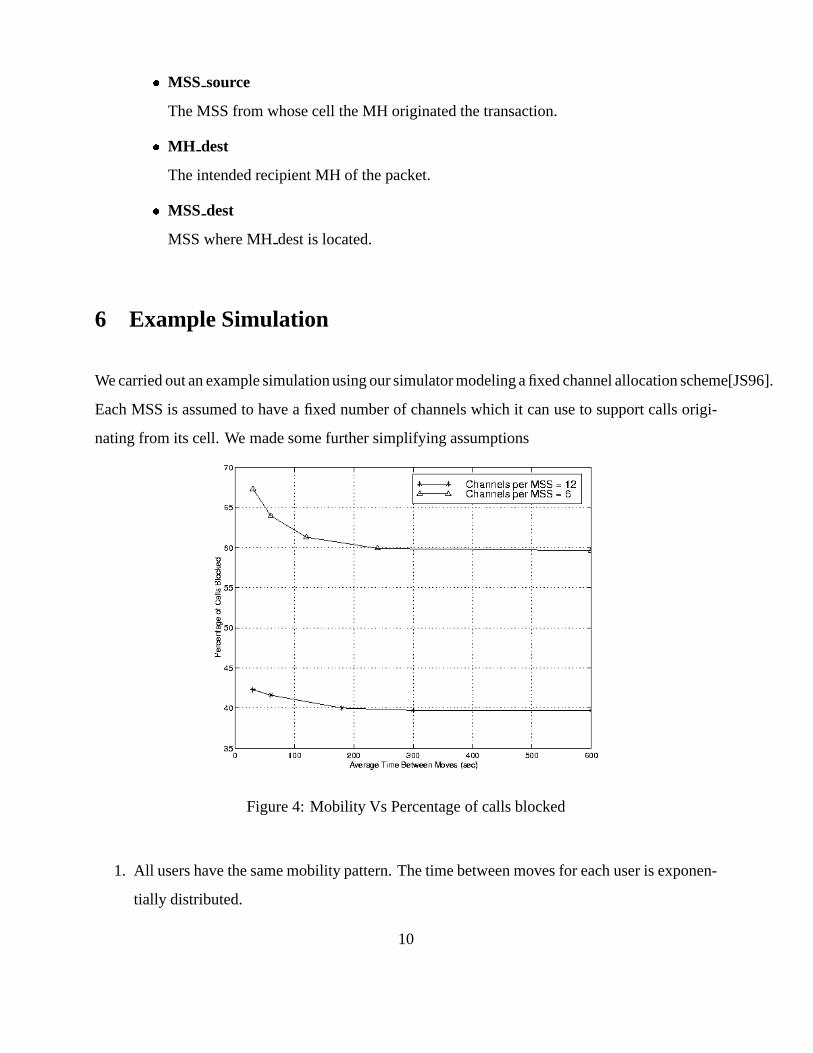
6 Example Simulation
We carried out an example simulation using our simulator modeling a fixed channel allocation scheme[JS96].
Each MSS is assumed to have a fixed number of channels which it can use to support calls origi-
nating from its cell. We made some further simplifying assumptions
Figure 4: Mobility Vs Percentage of calls blocked
1. All users have the same mobility pattern. The time between moves for each user is exponen-
tially distributed.
10

Figure 5: Comparative Distribution of Blocking
Figure 6: Comparative Distribution of Blocking
2. All users have the same calling pattern. No calls are attempted when the user is busy. The
time between calls for a user is exponentially distributed from the time his state becomes idle.
3. The duration of a call is exponentially distributed.
11

4. There is a point to point link between any two MSSs. ( This would be the case for example
when all MSSs are connected to an ATM switch.)
5. Location management is perfect. There is no overhead due to location management.
6. The calls between two MHs are for voice. Voice data is modeled as a a continuous stream
computed on the basis of 8 samples per second of 8 bits each. Also the intra packet end to
end delay must be less than 0.5 seconds for the voice quality to be satisfactory.
7. Wireless channels are 64Kbps each.
The system parameters were taken as follows
Parameter Distribution Default Value
Number of MSS - 50
Number of MHs - 700
Number of Channels / MSS - 12
Control message length - 320 bits
Voice Packet length - 16000 bits
Time between voice packets - 0.25s
Mobility Rate exponential 5 minutes
Calling Rate exponential 5 minutes
Call duration exponential 3 minutes
Channel capacity 64Kbps
Wired Links bandwidth 10 Mbps
Simulation Time 20min
6.1 Result
Calls are blocked, due to either the callee being busy, non availability of channels when initiating
the call, or disconnection of calls due to a free channel not being available on a busy MH’s move to
12

a new cell. As the mobility increases the number of calls disconnected due to mobility increases 6
whereas blocks due to other factors shows a decline. The overall call blocking rate also increases
with mobility 4. The increase in blocking probability is significant over a small range of inter-move
delay values. Thereafter, the effect is less pronounced as expected. Varying the number of channels
from 6 to 12 decreases the call blocking probability by almost a third.
7 Future Work
The simulation system developed as part of this coursework is highly flexible and scalable. It has
the potential to support different Channel Allocation, Location Management, Caching - Prefetching
techniques with different mobility and calling characteristics. All this has been done in a modular
fashion so that a change in one module can be done without altering any other modules.
Several features are yet to be implemented. Currently the simulator models only voice data. The
topology and wireless modules are modeled as simple delays assuming dedicated channels. Call
duration, call arrival rate and mobility patterns are modeled as exponential distributions. These
assumptions may have to be modified depending on the model under consideration. For example,
if a contention protocol is used on the wireless channel the assumption regarding dedicated channels
does not hold anymore. Similarly, a Markov process may not be a realistic model for mobility as
users do not have totally random movement patterns. For example, a user would move from his
place of work to home and back at fixed times during the day.
In the above example simulation we saw that the blocking probability is highly dependent on the
state of the callee when a caller makes a call. Callee sets should not necessarily be chosen at ran-
dom, as users have a fixed set of acquaintances, whom they call most often, besides making a few
random calls. Our emphasis for now was to provide a top level framework. The way the simula-
tion is designed, there are hooks to to modify/implement features, to simulate various solutions to
problems posed by mobility. This work provides us with the opportunity to compare and contrast
various schemes proposed in literature and then implement some of our own by learning from the
13

experience.
References
[Jor95] Scott Jordan. Resource allocation in wireless networks. Technical report, Northwestern
University, Department of Electrical Engineering and Computer Science, January 1995.
[JS96] Scott Jordan and Eric J. Schwabe. Worst -case performance of cellular channel assign-
ment policies. ACM Journal of Wireless Networks, 2, 1996.
[Sci94a] Scientific and Engineering Software, Inc., Austin, TX. SES/Workbench Sim Language
Reference, 3.1 edition, 1994.
[Sci94b] Scientific and Engineering Software, Inc., Austin, TX. SES/Workbench Simulating Mod-
els, 3.1 edition, 1994.
14


![Simulating Quantum Dynamics On A Quantum Computer · arXiv:1011.3489v2 [quant-ph] 27 May 2011 Simulating Quantum Dynamics On A Quantum Computer Nathan Wiebe,1,2 Dominic W. Berry,2](https://img.dokumen.tips/doc/110x75/5f07fbf17e708231d41fbef8/simulating-quantum-dynamics-on-a-quantum-computer-arxiv10113489v2-quant-ph-27.jpg)


![SIMULATING GROVER’S QUANTUM SEARCH IN A CLASSICAL COMPUTER · 2018-10-31 · arXiv:1003.1930v1 [cs.OH] 9 Mar 2010 SIMULATING GROVER’S QUANTUM SEARCH IN A CLASSICAL COMPUTER D.K](https://img.dokumen.tips/doc/110x75/5e4cd740208a1e5a9c0a101a/simulating-groveras-quantum-search-in-a-classical-computer-2018-10-31-arxiv10031930v1.jpg)