Embed Size (px)
Citation preview
1
Computational Lighting Reproduction for Facial Live Video with
Rigid Facial Motion
Takao Makino,1 Norimichi Tsumura,2 Koichi Takase,1
Keiichi Ochiai,1 Nobutoshi Ojima,3 and Toshiya Nakaguchi2
1Graduate School of Science and Technology,
Chiba University, 1-33 Yayoi-cho, Inage-ku,
Chiba 263-8522, Japan ([email protected],
[email protected], [email protected])
2Graduate School of Advanced Integrated Science,
Chiba University, 1-33 Yayoi-cho, Inage-ku, Chiba 263-8522,
Japan ([email protected], [email protected])
3Global R&D Beauty Creation, Kao Corporation, 2-1-3 Bunka,
Sumida-ku, Tokyo 131-8501, Japan ([email protected])
Abstract.
In this research, we develop a practical lighting reproduction technique to reproduce the
appearance of a face under an arbitrary lighting condition in a facial live video with rigid facial
motion. The reproduced facial image has texture detail and novel shading by combining image-based
components and model-based components. Our technique is practical because it only requires using
polarizing filters with the conventional green screen matting technique.
Keywords: relighting, compositing, environmental illumination, image-based rendering, model-based rendering,
face tracking

2
I. INTRODUCTION
Lighting reproduction is a very important technique used in various areas. For example, in
the film industry, lighting reproduction techniques have been used to reproduce an actor’s
appearance in various lighting conditions. Debevec et al.1 presented a technique for
reproducing a static facial image under varying lighting conditions. Wenger et al.2 presented
a lighting reproduction technique for actors in a performance. The lighting reproduction can
be used as a live simulator of a person applying cosmetics in a store by reproducing the facial
appearance under a particular lighting condition. If we can apply the lighting reproduction for
cosmetic simulators, we can simulate the appearance of the face of the person wearing
cosmetics in various lighting conditions. However, these lighting reproduction techniques
require a large apparatus, such as a once-subdivided icosahedron of more than 1.5 meters in
diameter1,2. A large apparatus is inappropriate for the cosmetic simulator because the
simulator is usually used in a small space, such as at a store counter.
In this paper, we develop a real-time lighting reproduction technique with a small
apparatus. The apparatus requires only adding polarizing filters to the conventional chroma-
key technique. Our technique reproduces the appearance of a face in a facial live video with
rigid facial motion in real time under an arbitrary environmental lighting condition. We use
both image-based components (captured live video image) and model-based components (3D
shape, surface normals and the bidirectional reflectance distribution function (BRDF))
instead of a large apparatus. By combining the image-based components and model-based
components, we can reproduce the facial appearance realistically in the live video stream.
The reproduced facial image has the detail texture from the image-based components and the
shading of the novel lighting from the model-based components.
In the next section, we briefly review related work in the area of facial relighting and real-
time processing. In Section III, we propose a computational lighting reproduction system for
facial live video. The geometry of this system, the computational shading and surface
reflection, the environmental mapping techniques and the face-tracking technique are
described in detail. In Section IV, we show our method to capture the background scene and
the sphere map of the video stream, and how we obtain the light sources existing in the
background scene. In Section V, we show the results of our system, and the effectiveness of
our system is demonstrated. Finally, in the last section, we conclude this paper.
3
II. RELATED WORK
Previous related work exists in two categories: facial relighting and real-time processing
systems. Numerous approaches have been proposed for these categories, but an exhaustive
survey is beyond the scope of this paper. We briefly review some representative studies that
provide the necessary background for our contribution.
In facial relighting, the parametric approach (model-based approach) is based on capturing
the geometry of the human face and calculating the BRDF at each point on the geometry.
Guenter et al.3 used six camera views and reconstructed the geometry based on the dot
correspondence on the face, and created texture maps for every frame of animation. Pighin et
al.4 re-synthesized facial animation through 3D model-based tracking and performed facial
relighting. Marschner et al.5 used a range scanner to capture the geometry, and captured the
spatially varying albedo texture by using polarizing filters in front of the camera and lights to
avoid surface reflection. We used a similar technique to capture only the diffuse reflectance
video. In the work of Marschner and Greenberg6, a uniform BRDF of surface reflection was
assigned on each vertex of the geometry. Recently, capturing the appearance with high
resolution7 and high accuracy8 has been achieved for realistic facial synthesis. Haro et al.9
proposed a fine-scale human skin structure by synthesizing the normal map of skin using a
texture synthesizing technique to reproduce the detail texture. However, this kind of detail
geometry is very difficult to handle in video processing. The detail texture is effectively
expressed by a ratio image. Marschner and Greenberg6 proposed using the ratio image for
relighting. The ratio image is calculated as the ratio between the reference images with and
without detail, and it is applied to another image without detail to add the detail texture. Liu
et al.10 proposed using the ratio image for expression synthesis. Paris et al.11 used the ratio
image to reproduce the detail texture of skin. In this paper, we use a similar technique to
replace the low spatial frequency component of the current shading image with that of the
target shading image by keeping the detail texture of shading. It should be noted that our
processes are only applied to the shading component in this paper. This is important to keep
the reality of the skin appearance in image-based processing.
A nonparametric approach (image-based approach) is essentially based on many images
taken under various directional lights. Realistic human faces can be obtained by this approach
without geometry. Debevec et al.1 proposed a lighting system for various directional lights

4
(Light Stage) and saved the images as relightable 3D face models. Hawkins et al.12 extended
the technique for variations in lighting for facial expressions. Wenger et al.2 achieved a
relightable 3D face video by using very high speed cameras to capture many images under
various directional lights in 1/30 second. Einarsson et al.13 extended this to record human
locomotion. Borshukov and Lewis14 combined an image-based model, an analytic surface
BRDF, and an image-space approximation for subsurface scattering to create highly realistic
face models for the movie industry. Peers et al.15 transferred reproduced facial appearances to
another subject. These techniques are used in the film industry for post-production to create
realistic compositions between the human face and environmental illuminants. However,
these techniques cannot be used for live video. Debevec et al.16 achieved live-action
composition between an on-site human and a stream of environmental maps with a special
lighting apparatus (Light Stage 3). This technique will be used effectively in the film industry
to enable an actor to perform in a previously captured environment while checking the
reproduction in real time. However, a special apparatus is required to light the face directly.
In this paper, we instead use a computational lighting approach.
In the real-time processing system for a live video stream, numerous approaches and
applications have been proposed (for example, see Open Source Computer Vision Library
(OpenCV library) by the Intel corporation17). We focus here on reviewing some recent work.
As described above, Debevec et al.16 achieved live-action composition between a human on-
site and a stream of environmental maps. Matusik and Pfister18 built a scalable system for
real-time acquisition, transmission, and display of 3D scenes. With the recent development of
programmable graphics hardware, it is becoming more effective for real-time processing to
process a video stream on graphics hardware. Tsumura et al.19 built the system and process to
control the skin melanin texture for a facial live stream as an e-cosmetic function. They
processed the pyramid decomposition and composition in programmable graphics hardware.
In this paper, we also use graphics hardware to accelerate the process of analysis for the
facial live stream.
III. COMPUTATIONAL LIGHTING REPRODUCTION SYSTEM
In this section, we describe the computational lighting reproduction system for the facial
live video and how we reproduce the appearance of the face in live video under arbitrary
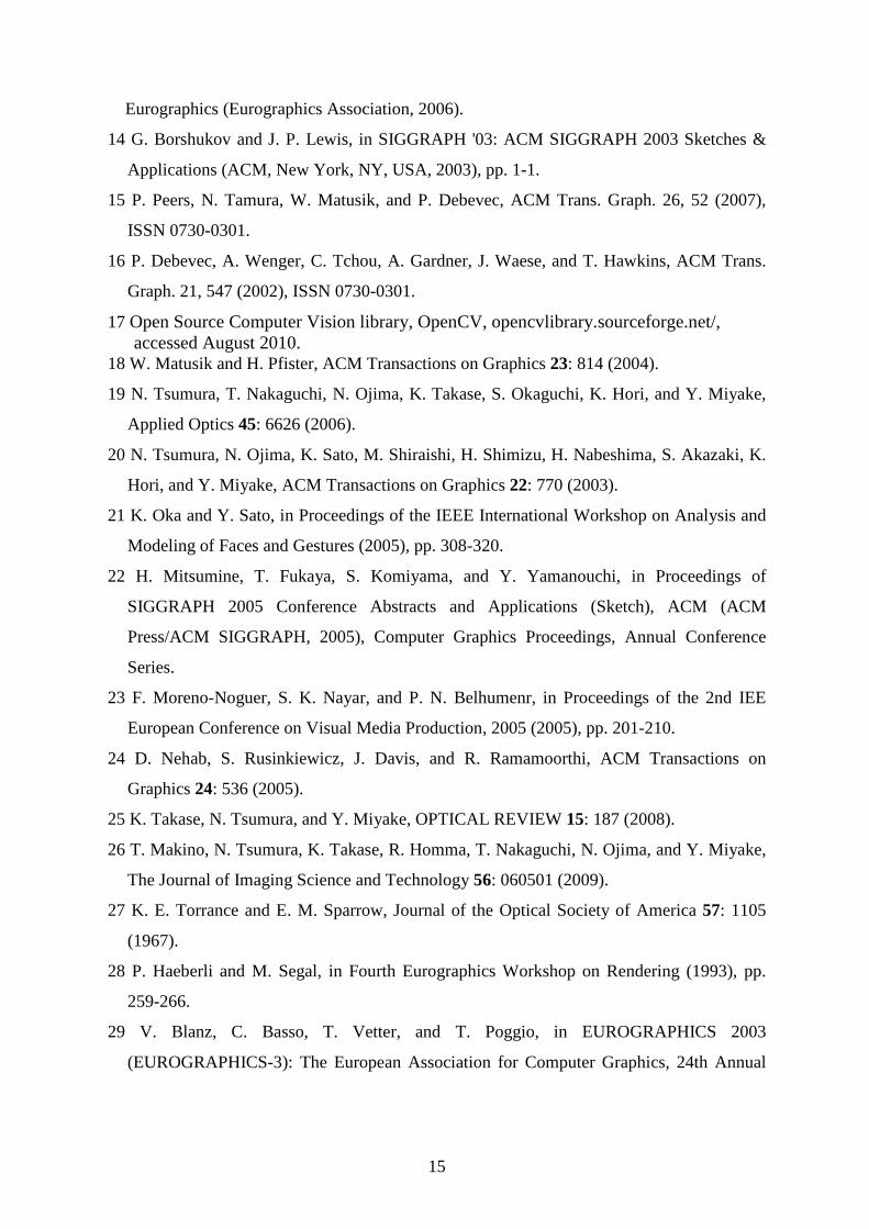
lighting conditions. Figure 1 shows the flow of the process of computational lighting

5
reproduction. It is performed by combining image-based components and model-based
components. Image-based components are the original facial shading and color components
of the facial live video stream. Model-based components are the shading and surface
reflection calculated with the pre-measured physical parameters of the face. The face is
captured with the video camera, and the camera and light sources are equipped with
polarizing filters. Polarizing filters are used to remove the surface reflection. The obtained
live video stream expresses the facial image of the diffuse reflection. This input facial live
video is separated into melanin, hemoglobin and shading components by the technique of
Tsumura et al.20. The image-based shading component is combined with the model-based
shading component. For position matching between the image-based and model-based
components, we track the rigid facial movement and estimate the facial rotation angle and
translation distance21. The computational lighting reproduction is performed by combining
the melanin and hemoglobin, combined shading, and model-based surface reflection.
A. Geometry of the system
The computational lighting reproduction system is shown in Fig. 2. The subject sits in a
chair in front of the green screen used for matting. One video camera views the face from a
distance of approximately one meter, and the captured facial live video stream is used as
input images. This system has three light sources for illuminating the face. For removing the
surface reflection, polarizing filters are attached in front of the light sources and the camera.
This system can render the shading and surface reflection components from the face model
and composite them into the diffuse reflection image of the face. This layout is easy to carry
and set up. It is thought that this system is practical compared to previous systems16,22,23.
B. Pre-measurement
For our facial lighting reproduction, we need to obtain the 3D shape, facial normal and
BRDF of the subject by the pre-measurement. Especially, BRDF measurement needs a large
or special measurement apparatus, such as those used in previous techniques1,2. In this paper,
we use the measurement method of combining 3D positions and normals24 for obtaining the
3D shape and normals, and the measurement method with linear light sources25 for obtaining
the BRDF. This BRDF measurement method can estimate BRDF parameters with a small
6
apparatus. In our other research, we constructed a small measurement system for all facial
physical parameters26.
The pre-measurement is needed only once per person before using the reproduction
system. Therefore, the pre-measurement system does not interfere with the practicality of our
proposed technique.
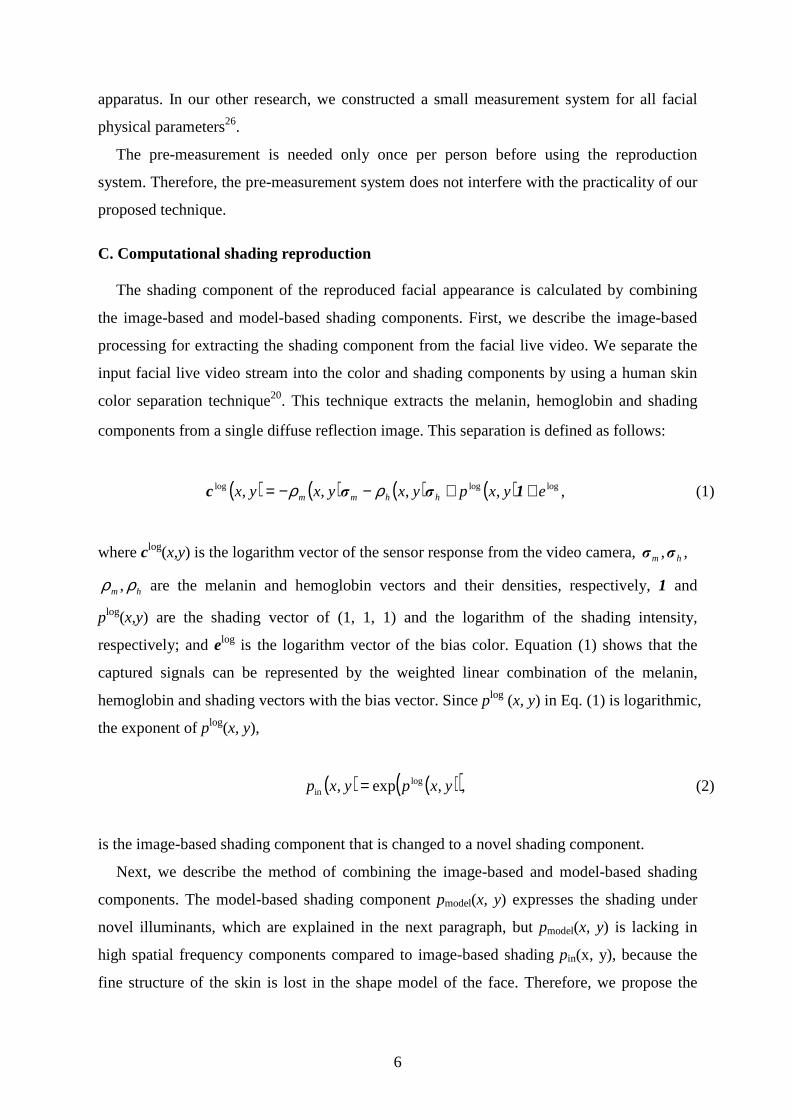
C. Computational shading reproduction
The shading component of the reproduced facial appearance is calculated by combining
the image-based and model-based shading components. First, we describe the image-based
processing for extracting the shading component from the facial live video. We separate the
input facial live video stream into the color and shading components by using a human skin
color separation technique20. This technique extracts the melanin, hemoglobin and shading
components from a single diffuse reflection image. This separation is defined as follows:
( ) ( ) ( ) ( ) ,,,,, logloglog eyxpyxyxyx hhmm ++−−= 1σσc ρρ (1)
where clog(x,y) is the logarithm vector of the sensor response from the video camera, hm σσ , ,
hm ρρ , are the melanin and hemoglobin vectors and their densities, respectively, 1 and
plog(x,y) are the shading vector of (1, 1, 1) and the logarithm of the shading intensity,
respectively; and elog is the logarithm vector of the bias color. Equation (1) shows that the
captured signals can be represented by the weighted linear combination of the melanin,
hemoglobin and shading vectors with the bias vector. Since plog (x, y) in Eq. (1) is logarithmic,
the exponent of plog(x, y),
( ) ( )( ),,exp, login yxpyxp = (2)
is the image-based shading component that is changed to a novel shading component.
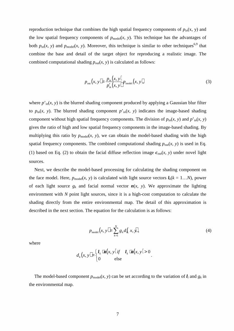
Next, we describe the method of combining the image-based and model-based shading
components. The model-based shading component pmodel(x, y) expresses the shading under
novel illuminants, which are explained in the next paragraph, but pmodel(x, y) is lacking in
high spatial frequency components compared to image-based shading pin(x, y), because the
fine structure of the skin is lost in the shape model of the face. Therefore, we propose the
7
reproduction technique that combines the high spatial frequency components of pin(x, y) and
the low spatial frequency components of pmodel(x, y). This technique has the advantages of
both pin(x, y) and pmodel(x, y). Moreover, this technique is similar to other techniques6,9 that
combine the base and detail of the target object for reproducing a realistic image. The
combined computational shading pout(x, y) is calculated as follows:
( ) ( )( ) ( ),,
,
,, model
in
inout yxp
yxp
yxpyxp
′= (3)
where p’ in(x, y) is the blurred shading component produced by applying a Gaussian blur filter
to pin(x, y). The blurred shading component p’ in(x, y) indicates the image-based shading
component without high spatial frequency components. The division of pin(x, y) and p’ in(x, y)
gives the ratio of high and low spatial frequency components in the image-based shading. By
multiplying this ratio by pmodel(x, y), we can obtain the model-based shading with the high
spatial frequency components. The combined computational shading pout(x, y) is used in Eq.
(1) based on Eq. (2) to obtain the facial diffuse reflection image cout(x, y) under novel light
sources.
Next, we describe the model-based processing for calculating the shading component on
the face model. Here, pmodel(x, y) is calculated with light source vectors lk(k = 1…N), power
of each light source gk and facial normal vector n(x, y). We approximate the lighting
environment with N point light sources, since it is a high-cost computation to calculate the
shading directly from the entire environmental map. The detail of this approximation is
described in the next section. The equation for the calculation is as follows:
( ) ( ),,,1
model ∑=
=N
kkk yxdgyxp (4)
where
( ) ( ) ( ) >⋅⋅
=else0
0,,,
yxifyxyxd kk
k
nlnl.
The model-based component pmodel(x, y) can be set according to the variation of li and gk in
the environmental map.
8
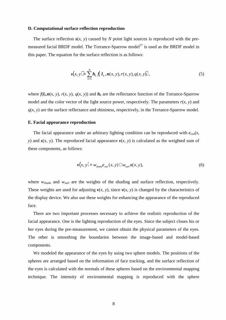
D. Computational surface reflection reproduction
The surface reflection s(x, y) caused by N point light sources is reproduced with the pre-
measured facial BRDF model. The Torrance-Sparrow model27 is used as the BRDF model in
this paper. The equation for the surface reflection is as follows:
( ) ( )∑=
=N
kkk yxqyxryxfyx
1
),(),,(),,(,, nlhs , (5)
where f(lk,n(x, y), r(x, y), q(x, y)) and hk are the reflectance function of the Torrance-Sparrow
model and the color vector of the light source power, respectively. The parameters r(x, y) and
q(x, y) are the surface reflectance and shininess, respectively, in the Torrance-Sparrow model.
E. Facial appearance reproduction
The facial appearance under an arbitrary lighting condition can be reproduced with cout(x,
y) and s(x, y). The reproduced facial appearance v(x, y) is calculated as the weighted sum of
these components, as follows:
( ) ),,(),(, surfoutshade yxwyxwyx scv += (6)
where wshade and wsurf are the weights of the shading and surface reflection, respectively.
These weights are used for adjusting v(x, y), since v(x, y) is changed by the characteristics of
the display device. We also use these weights for enhancing the appearance of the reproduced
face.
There are two important processes necessary to achieve the realistic reproduction of the
facial appearance. One is the lighting reproduction of the eyes. Since the subject closes his or
her eyes during the pre-measurement, we cannot obtain the physical parameters of the eyes.
The other is smoothing the boundaries between the image-based and model-based
components.
We modeled the appearance of the eyes by using two sphere models. The positions of the
spheres are arranged based on the information of face tracking, and the surface reflection of
the eyes is calculated with the normals of these spheres based on the environmental mapping
technique. The intensity of environmental mapping is reproduced with the sphere

9
environmental mapping technique28. As described in the next section, the video of this
environmental map is captured under the lighting condition, which is required for
reproduction. The size and BRDF of the spheres are decided empirically. The reproduced
appearance is rendered at the eye region of the face while the subject has his or her eyes open.
The boundaries between the image-based and model-based components are smoothly
connected by alpha blending. The face region is defined with the melanin and hemoglobin
components19,20. We applied the blur filter to the face regions for a smooth connection
between the face region and other regions, and we set the value of the blurred face region to
the value of the alpha blending.
F. Facial translation and rotation tracking
In previous subsections, we described the computational lighting reproduction techniques
with the assumption that position matching of the face image and face model had already
been performed. In this section, we describe how we match the face image and face model.
For matching, we must estimate the facial pose, i.e., the translation and rotation of the face. A
3D face model database is often used for matching the face image and the face model29,30.
However, these techniques are unsuitable for real-time processing. We use a particle filtering
technique21 for tracking the face and estimating the facial pose. The facial pose vector bt at
frame t is defined as follows:
),,,,,,( tttztytxtt TTT ψθφ=b (7)
where (Txt, Tyt, Tzt) is the translation distance, and (ϕt, θt, ψt) is the rotation angles of the roll,
pitch and yaw, respectively. In this particle filtering technique, the probability density
function of a facial pose is represented as a set of N discrete samples. This sample set is
defined as {b(i)t; π
(i)t}( i = 1…N). Each facial pose sample b(i)
t has a corresponding weight π(i)t.
Face tracking is performed with the following motion model:
,11)( ωτ ++′= −− tt
it vbb (8)
where b’ t-1 is the chosen sample from {b(i)t-1; π
(i)t-1},τ is the time interval, vt-1 is the velocity of
the facial pose, and ω is system noise. We generate a new set of N samples {b(i)t} with Eq. (8).
The weight of each new sample {π(i)t} is calculated with template matching between the input
10
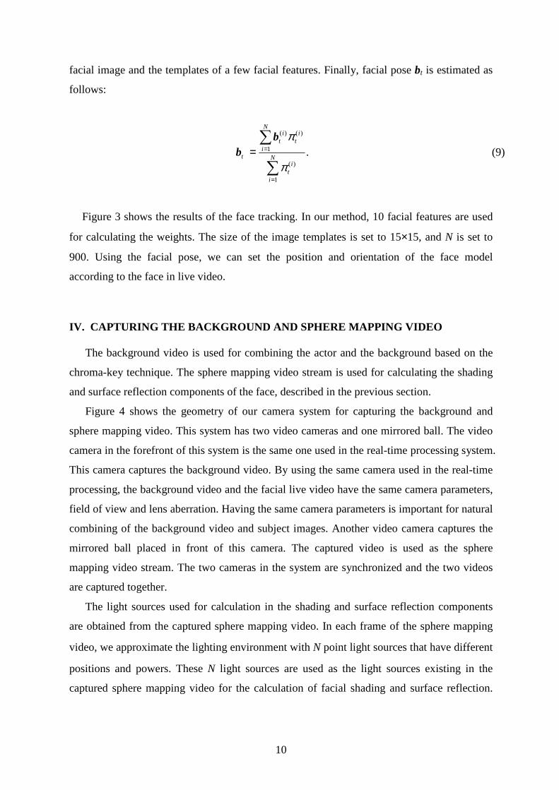
facial image and the templates of a few facial features. Finally, facial pose bt is estimated as
follows:
.
1
)(
1
)()(
∑
∑
=
==N
i
it
N
i
it
it
t
π
πbb (9)
Figure 3 shows the results of the face tracking. In our method, 10 facial features are used
for calculating the weights. The size of the image templates is set to 15×15, and N is set to
900. Using the facial pose, we can set the position and orientation of the face model
according to the face in live video.
IV. CAPTURING THE BACKGROUND AND SPHERE MAPPING VI DEO
The background video is used for combining the actor and the background based on the
chroma-key technique. The sphere mapping video stream is used for calculating the shading
and surface reflection components of the face, described in the previous section.
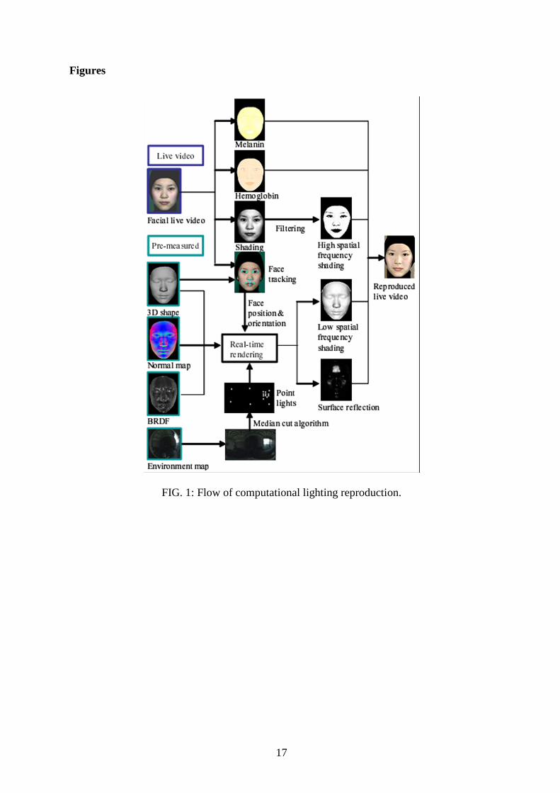
Figure 4 shows the geometry of our camera system for capturing the background and
sphere mapping video. This system has two video cameras and one mirrored ball. The video
camera in the forefront of this system is the same one used in the real-time processing system.
This camera captures the background video. By using the same camera used in the real-time
processing, the background video and the facial live video have the same camera parameters,
field of view and lens aberration. Having the same camera parameters is important for natural
combining of the background video and subject images. Another video camera captures the
mirrored ball placed in front of this camera. The captured video is used as the sphere
mapping video stream. The two cameras in the system are synchronized and the two videos
are captured together.
The light sources used for calculation in the shading and surface reflection components
are obtained from the captured sphere mapping video. In each frame of the sphere mapping
video, we approximate the lighting environment with N point light sources that have different
positions and powers. These N light sources are used as the light sources existing in the
captured sphere mapping video for the calculation of facial shading and surface reflection.
11
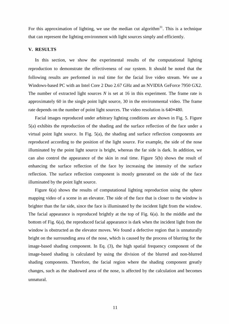
For this approximation of lighting, we use the median cut algorithm31. This is a technique
that can represent the lighting environment with light sources simply and efficiently.
V. RESULTS
In this section, we show the experimental results of the computational lighting
reproduction to demonstrate the effectiveness of our system. It should be noted that the
following results are performed in real time for the facial live video stream. We use a
Windows-based PC with an Intel Core 2 Duo 2.67 GHz and an NVIDIA GeForce 7950 GX2.
The number of extracted light sources N is set at 16 in this experiment. The frame rate is
approximately 60 in the single point light source, 30 in the environmental video. The frame
rate depends on the number of point light sources. The video resolution is 640×480.
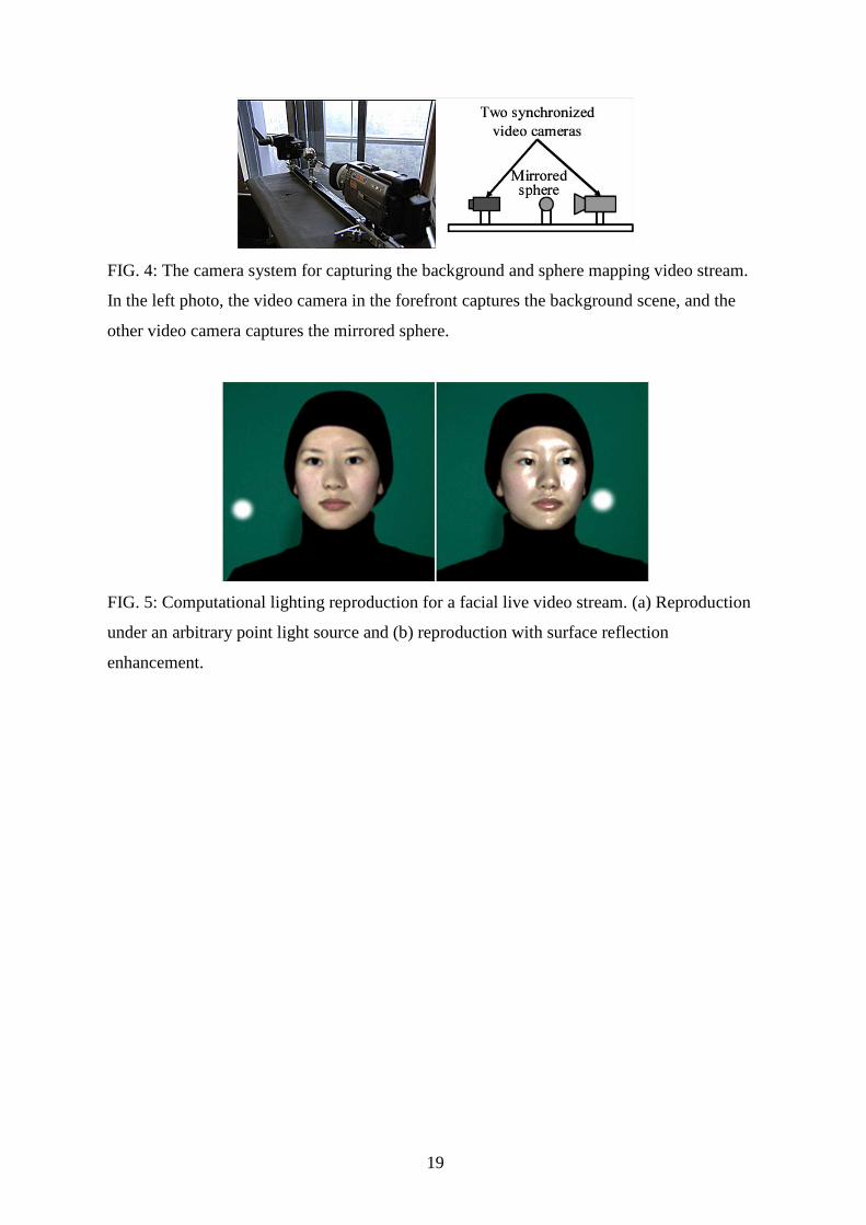
Facial images reproduced under arbitrary lighting conditions are shown in Fig. 5. Figure
5(a) exhibits the reproduction of the shading and the surface reflection of the face under a
virtual point light source. In Fig. 5(a), the shading and surface reflection components are
reproduced according to the position of the light source. For example, the side of the nose
illuminated by the point light source is bright, whereas the far side is dark. In addition, we
can also control the appearance of the skin in real time. Figure 5(b) shows the result of
enhancing the surface reflection of the face by increasing the intensity of the surface
reflection. The surface reflection component is mostly generated on the side of the face
illuminated by the point light source.
Figure 6(a) shows the results of computational lighting reproduction using the sphere
mapping video of a scene in an elevator. The side of the face that is closer to the window is
brighter than the far side, since the face is illuminated by the incident light from the window.
The facial appearance is reproduced brightly at the top of Fig. 6(a). In the middle and the
bottom of Fig. 6(a), the reproduced facial appearance is dark when the incident light from the
window is obstructed as the elevator moves. We found a defective region that is unnaturally
bright on the surrounding area of the nose, which is caused by the process of blurring for the
image-based shading component. In Eq. (3), the high spatial frequency component of the
image-based shading is calculated by using the division of the blurred and non-blurred
shading components. Therefore, the facial region where the shading component greatly
changes, such as the shadowed area of the nose, is affected by the calculation and becomes
unnatural.

12
Figure 6(b) shows the results of the computational lighting reproduction under an
environment of fireworks. In the top of Fig. 6(b), the right side of the reproduced face is
bright whereas the left side is dark, since both fireworks are on the right side of the face. The
surface reflection is also highly generated on the right side of the reproduced face. In the
middle of Fig. 6(b), the whole area of the reproduced face is illuminated equally, since both
fireworks are on each side of the face. In the bottom of Fig. 6(b), the reproduced face is very
bright since both of the fireworks are in front of the face. These images show that we can
reproduce the variation of shading and surface reflection according to the movement of the
illuminating objects.
Figure 7 shows another live video reproduced under various kinds of environmental
illuminants. It is shown that our technique can reproduce convincing results for face
composition in various scenes.
VI. CONCLUSION AND DISCUSSION
The appearance of a face in a facial live video was reproduced in real time under an
arbitrary environmental illuminant by using our computational lighting reproduction system.
The results of experiments using this system confirmed the effectiveness of the system.
In the reproduction of a human, the appearance of the hair and the clothes is very
important for reproducing a realistic appearance. However, our system can reproduce only
the appearance of the face with rigid facial motion. Therefore, at this time we must use a
black cloth and a hair band to avoid showing the shade and surface reflection on the hair and
clothes. One aspect of our future work is to investigate a real-time lighting reproduction
system for a subject’s hair and clothes.
The appearance of reproduced facial images also depends on the measured facial physical
properties. We can reproduce more realistic surface reflection and shading by using more
accurate properties. Thus, we need to improve the measurement system for facial properties.
Another approach of future work is to apply facial expressions to the facial 3D shape. The
face tracking technique used in our system cannot track the facial expression. For this
problem, effective techniques already track the facial expression, such as the techniques
proposed by Dornaika and Davoine32. By adopting these techniques, our system will be able
to track the facial expression. The result of facial expression tracking could be used to deform

13
the 3D shape of the face in a live video. We may also be able to apply the morphing
technique of ratio images to express the change of facial expression, as was done by Liu et
al.10.
In addition, we need to solve the problem that there is an unnaturally bright region on the
surrounding area of the nose. We think this problem may be solved by considering the facial
geometry in the blurring process in Eq. (3). However, we think that such blurring is difficult
to implement and run in real time. Resolving this problem is also our future work.
We will reproduce the appearance of the face applying cosmetics under the arbitrary
environmental illuminant by using our reproduction technique and the reflectance property of
cosmetics. Finally, we will apply our technique in a live simulator of a person applying
cosmetics in a store.
Acknowledgment
This research was supported in part by a Grant-in-Aid for Scientific Research (19360026)
from the Japan Society for the Promotion of Science.
14
REFERENCES
1 P. Debevec, T. Hawkins, C. Tchou, H. P. Duiker, W. Sarokin, and M. Sagar, in
Proceedings of SIGGRAPH2000, ACM (ACM Press/ACM SIGGRAPH, 2000), Computer
Graphics Proceedings, Annual Conference Series, pp. 145-156.
2 A. Wenger, A. Gardner, C. Tchou, J. Unger, T. Hawkins, and P. Debevec, ACM
Transactions on Graphics 24: 756 (2005).
3 B. Guenter, C. Grimm, D. Wood, H. Malvar, and F. Pighin, in Proceedings of SIGGRAPH
1998, ACM (ACM Press/ACM SIGGRAPH, 1998), Computer Graphics Proceedings,
Annual Conference Series, pp. 55-66.
4 F. Pighin, R. Szeliski, and D. H. Salesin, in Proceedings of Seventh IEEE International
Conference on Computer Vision (IEEE, 1999), pp. 143-150.
5 S. Marschner, B. Guneter, and S. Raghupathy, in Proceedings of Eurographics Symposium
on Rendering, Eurographics (Eurographics Association, 2000), pp. 231-242.
6 S. R. Marschner and D. P. Greenberg, in Fifth Color Imaging Conference (1997), pp. 262-
265.
7 L. Zhang, N. Snavely, B. Curless, and S. M. Seitz, ACM Transactions on Graphics 23: 548
(2004).
8 T. Weyrich, W. Matusik, H. Pfister, B. Bickel, C. Donner, C. Tu, J. McAndless, J. Lee, A.
Ngan, H. W. Jensen, et al., ACM Transactions on Graphics 25: 1013 (2006).
9 A. Haro, I. A. Essa, and B. K. Guenter, in Proceedings of the 12th Eurographics Workshop
on Rendering Techniques (Springer-Verlag, London, UK, 2001), pp. 53-62, ISBN 3-211-
83709-4.
10 Z. Liu, Y. Shan, and Z. Zhang, in SIGGRAPH '01: Proceedings of the 28th Annual
Conference on Computer Graphics and Interactive Techniques (ACM, New York, NY,
USA, 2001), pp. 271-276, ISBN 1-58113-374-X.
11 S. Paris, F. X. Sillion, and L. Quan, in Proceedings of Pacific Graphics (2003), p. 41.
12 T. Hawkins, A. Wenger, C. Tchou, A. Gardner, F. Goransson, and P. Debevec, in
Proceedings of Eurographics Symposium on Rendering, Eurographics (Eurographics
Association, 2004), pp. 309-319.
13 P. Einarsson, C.-F. Chabert, A. Jones, W.-C. Ma, B. Lamond, T. Hawkins, M. Bolas, S.
Sylwan, and P. Debevec, in Proceedings of Eurographics Symposium on Rendering,
15
Eurographics (Eurographics Association, 2006).
14 G. Borshukov and J. P. Lewis, in SIGGRAPH '03: ACM SIGGRAPH 2003 Sketches &
Applications (ACM, New York, NY, USA, 2003), pp. 1-1.
15 P. Peers, N. Tamura, W. Matusik, and P. Debevec, ACM Trans. Graph. 26, 52 (2007),
ISSN 0730-0301.
16 P. Debevec, A. Wenger, C. Tchou, A. Gardner, J. Waese, and T. Hawkins, ACM Trans.
Graph. 21, 547 (2002), ISSN 0730-0301.
17 Open Source Computer Vision library, OpenCV, opencvlibrary.sourceforge.net/, accessed August 2010.
18 W. Matusik and H. Pfister, ACM Transactions on Graphics 23: 814 (2004).
19 N. Tsumura, T. Nakaguchi, N. Ojima, K. Takase, S. Okaguchi, K. Hori, and Y. Miyake,
Applied Optics 45: 6626 (2006).
20 N. Tsumura, N. Ojima, K. Sato, M. Shiraishi, H. Shimizu, H. Nabeshima, S. Akazaki, K.
Hori, and Y. Miyake, ACM Transactions on Graphics 22: 770 (2003).
21 K. Oka and Y. Sato, in Proceedings of the IEEE International Workshop on Analysis and
Modeling of Faces and Gestures (2005), pp. 308-320.
22 H. Mitsumine, T. Fukaya, S. Komiyama, and Y. Yamanouchi, in Proceedings of
SIGGRAPH 2005 Conference Abstracts and Applications (Sketch), ACM (ACM
Press/ACM SIGGRAPH, 2005), Computer Graphics Proceedings, Annual Conference
Series.
23 F. Moreno-Noguer, S. K. Nayar, and P. N. Belhumenr, in Proceedings of the 2nd IEE
European Conference on Visual Media Production, 2005 (2005), pp. 201-210.
24 D. Nehab, S. Rusinkiewicz, J. Davis, and R. Ramamoorthi, ACM Transactions on
Graphics 24: 536 (2005).
25 K. Takase, N. Tsumura, and Y. Miyake, OPTICAL REVIEW 15: 187 (2008).
26 T. Makino, N. Tsumura, K. Takase, R. Homma, T. Nakaguchi, N. Ojima, and Y. Miyake,
The Journal of Imaging Science and Technology 56: 060501 (2009).
27 K. E. Torrance and E. M. Sparrow, Journal of the Optical Society of America 57: 1105
(1967).
28 P. Haeberli and M. Segal, in Fourth Eurographics Workshop on Rendering (1993), pp.
259-266.
29 V. Blanz, C. Basso, T. Vetter, and T. Poggio, in EUROGRAPHICS 2003
(EUROGRAPHICS-3): The European Association for Computer Graphics, 24th Annual

16
Conference, The Eurographics Association (Blackwell, 2003), vol. 22 of Computer
Graphics Forum, pp. 641-650.
30 V. Blanz, K. Scherbaum, T. Vetter, and H.-P. Seidel, in The European Association for
Computer Graphics 25th Annual Conference EUROGRAPHICS 2004, edited by M.-P.
Cani and M. Slater (Blackwell, 2004), vol. 23 of Computer Graphics Forum, pp. 669-676,
ISBN 0167-7055.
31 P. Debevec, in Proceedings of SIGGRAPH 2005 Conference Abstracts and Applications
(Poster), ACM (ACM Press/ACM SIGGRAPH, 2005), Computer Graphics Proceedings,
Annual Conference Series.
32 F. Dornaika and F. Davoine, in Proceedings of Conference on Computer Vision and
Pattern Recognition Workshop (2004), vol. 10, p. 153.
17
Figures
FIG. 1: Flow of computational lighting reproduction.

18
FIG. 2: Geometry of our computational lighting reproduction system. The subject is
illuminated by three light sources and captured by the video camera. Polarizing filters are
attached in front of the light sources and the camera for removing the surface reflection on
the face. The green screen is used for matting. The captured facial video stream is used as
input images for the computational lighting reproduction process.
FIG. 3: The results of face tracking. The gray circle shows the center of the face, and the ten
white circles in each reproduction show the ten feature points tracked.
19
FIG. 4: The camera system for capturing the background and sphere mapping video stream.
In the left photo, the video camera in the forefront captures the background scene, and the
other video camera captures the mirrored sphere.
FIG. 5: Computational lighting reproduction for a facial live video stream. (a) Reproduction
under an arbitrary point light source and (b) reproduction with surface reflection
enhancement.

20
FIG. 6: Results of the reproduction under two conditions. (a) Results of the reproduction
under the lighting condition of an elevator. (b) Results of the computational lighting
reproduction in the environment of fireworks. In these results, the sphere mapping video
stream is used as mirrored sphere images.
FIG. 7: Reproduced live video under various kinds of environmental illuminants.