Embed Size (px)
Citation preview
Efficient Suturing of Deformable Models
Georges Younes, Julien abi-Nahed, and George Turkiyyah
Abstract Suturing is a fundamental operation in surgical procedures. Simulationof suturing involves the simulation of needle–tissue and thread–tissue interaction,as well as contact between sutured boundaries. In this work, robust methods areproposed for an efficient finite element-based suture simulation. Contact conditionsare modeled using complementarity relations. By exploiting adjacency relationshipsinherent to simplicial meshes and decomposing rigid body motion into slidingand bulk-deforming components, needle driving can be simulated in real timewithout introducing any new mesh elements. In addition, a computationally efficientformulation of thread pulling is presented. These techniques are implemented andtested in a prototype system which allows for interactive simulation of suturing withhigh resolution models.
1 Introduction
Suturing is a fundamental operation in surgical procedures. It is an ever-presenttask in procedures ranging from the closing of lacerations and stitching of woundsin open surgery, to anastomosis and closing of incisions after tissue removal inlaparoscopic and robotic-assisted procedures. The techniques for planning suturing
G. Younes (�)Department of Computer Science, American University of Beirut, Beirut, Lebanon
Qatar Robotic Surgery Centre, Qatar Science & Technology Park, Qatar Foundation, Doha, Qatar
J. abi-NahedQatar Robotic Surgery Centre, Qatar Science & Technology Park, Qatar Foundation, Doha, Qatar
G. TurkiyyahDepartment of Computer Science, American University of Beirut, Beirut, Lebanon
A. Wittek et al. (eds.), Computational Biomechanics for Medicine: Models, Algorithmsand Implementation, DOI 10.1007/978-1-4614-6351-1 8,© Springer Science+Business Media New York 2013
75
76 G. Younes et al.
tasks and the manual dexterity involved in executing them are essential skillsthat student surgeons and practitioners develop through training and practice. Inthe context of laparoscopic and robotic-assisted surgery, with their constrainedworkspace due to instrument kinematics, this practice often has a steep learningcurve, and it takes a substantial amount of training to perfect the necessary skills.The practice generally takes place on suturing boards, phantom models, or liveanimals (w/o on), but there has been significant interest in the use of simulation-based training tools because of the flexibility in the training scenarios that thesimulators can provide, their convenience, and their ultimate cost-effectiveness.
The development of surgical training simulators and procedure-rehearsal systemsrequires reliable models for suture simulation that can pass the tests of face andcontent validity. The importance of this problem has led to a number of efforts formodeling various aspects of the suturing task. In particular, finite element modelsfor needle insertion and steering inside soft tissue have been described in [1, 2]. Inthese works, node repositioning, additions, and local remeshing are performed ina two-dimensional or three-dimensional volumetric finite element mesh to supportthe compatible sliding and sticking movements of a needle inside the mesh. Duriezet al. [3] describe a flexible needle insertion model that does not remesh locallybut instead uses complementarity constraints to tie points on the needle to theelements of the tissue mesh. This strategy has obvious computational savings andallows realistic biopsy and brachytherapy simulations to be performed. Another setof research efforts [4,5] has focused on experiments intended to produce realistic invivo and in vitro values for friction forces, puncture thresholds, and other parametersneeded in validated simulations. Contact involving rigid tools and deformablemodels have been studied in physically based surgical simulations and related hapticenvironments. Laycock and Day [6] survey some early models that have beenproposed for generating contact forces. More recent works have successfully usedmodels involving linear complementarity relations between gaps and reaction forces[7,8] to handle contact. Methods for collision detection for deformable models havebeen described in [9, 10].
In the context of suturing simulations, an early work [11] used constraints tomodel suture closing in a finite element model. A model that uses a spline endowedwith a continuum dynamic model and sliding constraints was proposed in [12].Wittek et al. [13] simulate needle insertion into the brain with high fidelity andprecision using a predictive nonlinear biomechanical tissue model that accounts forlarge deformations, but it is not clear if it can produce haptic rates of interactionfor realistic models. Guebert et al. [7] propose a promising simulation based oncomplementarity constraint modeling of all interactions between surgical threadsand the embedding soft tissue. Choi et al. [14] describe a suturing system using thephysics available in a commodity physics engine including line springs and chainedlinear segments. Mass-spring chains have also been proposed for thread modeling.Despite these and related efforts however, there is not yet a satisfactory suturingsimulation model that has sufficient realism and interactive response rate, suitablefor training medical students and related professionals.
The difficulties of modeling of suturing operations come from a number offactors. An inextensible thread, essentially massless, with almost negligible bending
Efficient Suturing of Deformable Models 77
stiffness is driven by a rigid tool in a highly deformable anatomically complex,heterogeneous, anisotropic soft tissue environment. The topology of the environ-ment is continuously changing because of the needle movement and the generalcontact conditions between the deforming tissue being sutured as well as betweentools, threads, and tissue. These simulations have to be performed in a limitedcomputational budget to allow for interactive use operations that support real-timevisual feedback and haptic interaction.
The main contribution of this chapter is a computationally effective model thatallows threads to be inserted into neighboring soft tissue volumes and pulled at twopoints to close an opening in real time and in a mechanically plausible fashion.The model introduces efficient geometric operations to allow needle and threadto traverse multiple boundaries and builds the appropriate constraints to use ina finite element model. We take advantage of the rigid nature of the needle todecompose driving motion into sliding and bulk-deforming components and handlethem separately. We also introduce a new thread pulling constraint model anddemonstrate it on a realistic example of an anastomosis procedure involving a finemesh with multiple puncture points.
The rest of this chapter is organized as follows. In Sect. 2 we describe how three-dimensional inter-boundary contact is handled in the context of a finite elementmodel. In Sect. 3, we describe how we model needle driving and puncturing ofmultiple tissue boundaries. Section 4 presents a thread pulling model, suitable forsingle stitches as well as running sutures, to close openings between two boundaries.Section 5 shows results and concludes.
2 Interaction Modeling and Contact Handling
In this chapter, deformable models are simulated using a quasi-static finite elementmodel. At every step of the simulation Kx = f is solved, where x is a vector withthe geometric positions of the n0 nodes, K is a 3n0 × 3n0 (stiffness) matrix, and fcontains the external forces.
The solution x can be constrained with the aid of algebraic constraints of the formCix= bi. The constraints linearly couple a subset of x and are solved by augmentingthe original system: [
K Ct
C 0
]{Xλ
}=
[fb
](1)
where C = [C0; C1; . . . ; Cm] and b = [b0; b1; . . . ; bm]. This system can be solvedefficiently by precomputing the Cholesky decomposition of K at the start of thesimulation and reusing it with backward/forward passes and different right-handsides.
This constraint framework allows us to model complex interactions betweenthe different objects that are being simulated, for example, a vertex v can befixed at position v0 by adding a constraint of the form: g(v) = v0, where g(s)returns the geometric positions of the vertices of a simplex s. In addition, Vertex–
78 G. Younes et al.
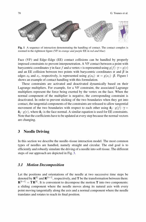
Fig. 1 A sequence of interaction demonstrating the handling of contact. The contact complex iszoomed in the rightmost figure (VF in orange and purple EE in red and blue)
Face (VF) and Edge–Edge (EE) contact collisions can be handled by properlyimposed constraints to prevent interpenetration. A VF contact between a point withbarycentric coordinates γ in face f and a vertex v is represented using g( f ) ·γ = g(v)and an EE collision between two points with barycentric coordinates α and β inedges e0 and e1, respectively, is represented using g(e0) ·α = g(e1) · β . Figure 1shows an example of contact handling with this formulation.
These constraints are activated and deactivated dynamically based on theirLagrange multipliers. For example, for a VF constraint, the associated Lagrangemultipliers represent the force being exerted by the vertex on the face. When thenormal component of the multiplier is negative, the corresponding constraint isdeactivated. In order to prevent sticking of the two boundaries when they get intocontact, the tangential components of the constraints are released to allow tangentialmovement of the two boundaries with respect to each other using n f · g( f ) · γ =n f ·g(v), where n f is the face normal. A similar equation is used for EE constraints.Note that the coefficients have to be updated at every step because the normal vectorsare changing.
3 Needle Driving
In this section we describe the needle–tissue interaction model. The most commontypes of needles are handled, namely straight and circular. The end goal is toefficiently and robustly simulate the driving of a needle into soft tissue. The differentsteps of our approach are depicted in Fig. 3.
3.1 Motion Decomposition
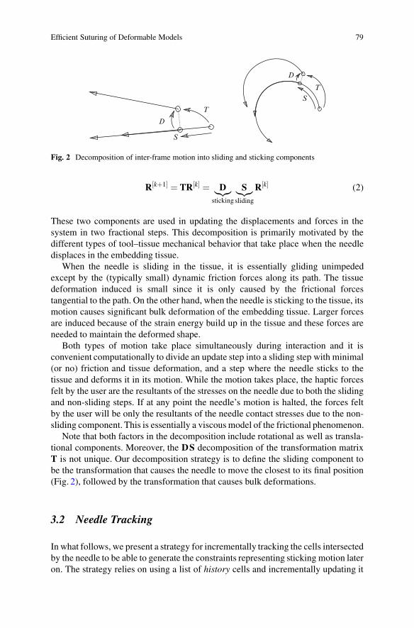
Let the positions and orientations of the needle at two successive time steps bedenoted by R[k] and R[k+1], respectively, and T be the transformation between them:R[k+1] = TR[k]. It is convenient to decompose the motion T into two components:a sliding component where the needle moves along its natural axis with everypoint moving tangentially along the axis and a normal component where the needletranslates and rotates to reach its final position.
Efficient Suturing of Deformable Models 79
T
S
D
T
S
D
Fig. 2 Decomposition of inter-frame motion into sliding and sticking components
R[k+1] = TR[k] = D︸︷︷︸sticking
S︸︷︷︸sliding
R[k] (2)
These two components are used in updating the displacements and forces in thesystem in two fractional steps. This decomposition is primarily motivated by thedifferent types of tool–tissue mechanical behavior that take place when the needledisplaces in the embedding tissue.
When the needle is sliding in the tissue, it is essentially gliding unimpededexcept by the (typically small) dynamic friction forces along its path. The tissuedeformation induced is small since it is only caused by the frictional forcestangential to the path. On the other hand, when the needle is sticking to the tissue, itsmotion causes significant bulk deformation of the embedding tissue. Larger forcesare induced because of the strain energy build up in the tissue and these forces areneeded to maintain the deformed shape.
Both types of motion take place simultaneously during interaction and it isconvenient computationally to divide an update step into a sliding step with minimal(or no) friction and tissue deformation, and a step where the needle sticks to thetissue and deforms it in its motion. While the motion takes place, the haptic forcesfelt by the user are the resultants of the stresses on the needle due to both the slidingand non-sliding steps. If at any point the needle’s motion is halted, the forces feltby the user will be only the resultants of the needle contact stresses due to the non-sliding component. This is essentially a viscous model of the frictional phenomenon.
Note that both factors in the decomposition include rotational as well as transla-tional components. Moreover, the DS decomposition of the transformation matrixT is not unique. Our decomposition strategy is to define the sliding component tobe the transformation that causes the needle to move the closest to its final position(Fig. 2), followed by the transformation that causes bulk deformations.
3.2 Needle Tracking
In what follows, we present a strategy for incrementally tracking the cells intersectedby the needle to be able to generate the constraints representing sticking motion lateron. The strategy relies on using a list of history cells and incrementally updating it
80 G. Younes et al.
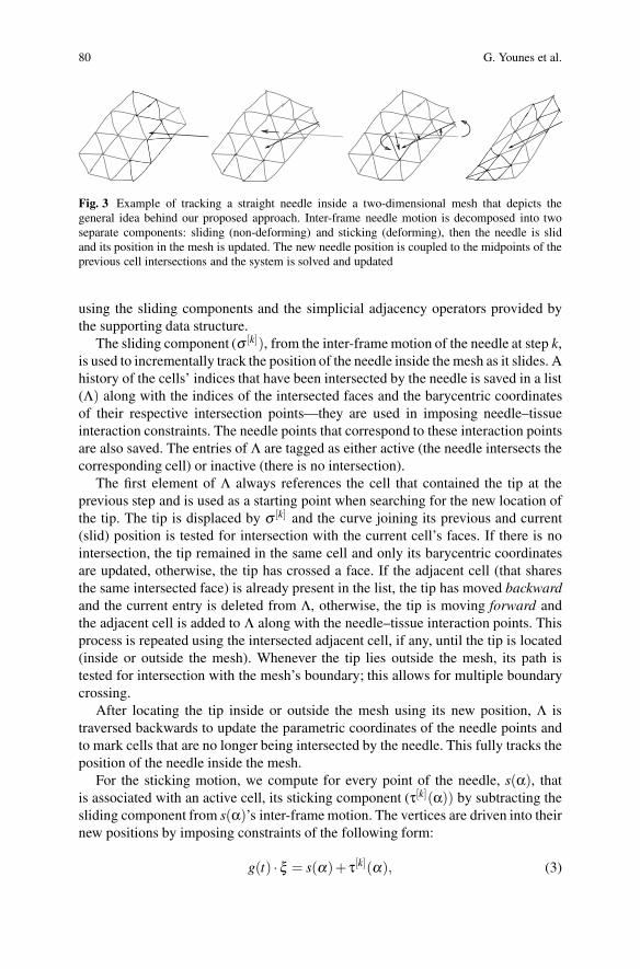
Fig. 3 Example of tracking a straight needle inside a two-dimensional mesh that depicts thegeneral idea behind our proposed approach. Inter-frame needle motion is decomposed into twoseparate components: sliding (non-deforming) and sticking (deforming), then the needle is slidand its position in the mesh is updated. The new needle position is coupled to the midpoints of theprevious cell intersections and the system is solved and updated
using the sliding components and the simplicial adjacency operators provided bythe supporting data structure.
The sliding component (σ [k]), from the inter-frame motion of the needle at step k,is used to incrementally track the position of the needle inside the mesh as it slides. Ahistory of the cells’ indices that have been intersected by the needle is saved in a list(Λ) along with the indices of the intersected faces and the barycentric coordinatesof their respective intersection points—they are used in imposing needle–tissueinteraction constraints. The needle points that correspond to these interaction pointsare also saved. The entries of Λ are tagged as either active (the needle intersects thecorresponding cell) or inactive (there is no intersection).
The first element of Λ always references the cell that contained the tip at theprevious step and is used as a starting point when searching for the new location ofthe tip. The tip is displaced by σ [k] and the curve joining its previous and current(slid) position is tested for intersection with the current cell’s faces. If there is nointersection, the tip remained in the same cell and only its barycentric coordinatesare updated, otherwise, the tip has crossed a face. If the adjacent cell (that sharesthe same intersected face) is already present in the list, the tip has moved backwardand the current entry is deleted from Λ, otherwise, the tip is moving forward andthe adjacent cell is added to Λ along with the needle–tissue interaction points. Thisprocess is repeated using the intersected adjacent cell, if any, until the tip is located(inside or outside the mesh). Whenever the tip lies outside the mesh, its path istested for intersection with the mesh’s boundary; this allows for multiple boundarycrossing.
After locating the tip inside or outside the mesh using its new position, Λ istraversed backwards to update the parametric coordinates of the needle points andto mark cells that are no longer being intersected by the needle. This fully tracks theposition of the needle inside the mesh.
For the sticking motion, we compute for every point of the needle, s(α), thatis associated with an active cell, its sticking component (τ[k](α)) by subtracting thesliding component from s(α)’s inter-frame motion. The vertices are driven into theirnew positions by imposing constraints of the following form:
g(t) ·ξ = s(α)+ τ[k](α), (3)
Efficient Suturing of Deformable Models 81
where ξ are the barycentric coordinates of the midpoints of the needle segmentinside one of Λ’s cells with tetrahedron index t. The Lagrange multipliers associatedwith these constraints are used to compute the resultant forces.
4 Thread Pulling
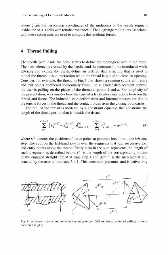
The needle path inside the body serves to define the topological path in the mesh.The mesh elements crossed by the needle, and the puncture points introduced whileentering and exiting the mesh, define an ordered data structure that is used tomodel the thread–tissue interaction while the thread is pulled to close an opening.Consider, for example, the thread in Fig. 4 that shows a running suture with entryand exit points numbered sequentially from 1 to n. Under displacement control,the user is pulling on the pieces of the thread at points 1 and n. For simplicity ofthe presentation, we consider here the case of a frictionless interaction between thethread and tissue. The induced tissue deformation and internal stresses are due tothe tensile forces in the thread and the contact forces from the closing boundaries.
The pull of the thread is modeled by a constraint equation that constrains thelength of the thread portion that is outside the tissue,
n/2−1
∑j=1
(x[k+1]
2 j − x[k+1]2 j+1
)· d[k]
2 j,2 j+1 =n/2−1
∑j=1
�[k]2 j,2 j+1 −Δ�[k+1], (4)
where x[k] denotes the positions of tissue points at puncture locations at the kth timestep. The sum on the left-hand side is over the segments that join successive exitand entry points along the thread. Every term in the sum represents the length ofsuch a segment as described below. �[k] is the length of the corresponding portionof the engaged straight thread at time step k and Δ�[k+1] is the incremental pullenacted by the user at time step k+ 1. This constraint presumes and is active only
1
23
. . .
n−1
n
p[k]
p[k+1]
q[k]
q[k+1]
[k]
[k+1]
d[k]
Fig. 4 Sequence of puncture points in a running suture (left) and linearization of pulling distanceconstraint (right)
82 G. Younes et al.
when the thread is fully engaged and has no slack. As long as the right-hand side isless than the actual length of the thread between the two end points, pulling causespure sliding until the thread is fully engaged. The scalar Lagrange multiplier of thisconstraint corresponds to the tensile force in the thread as it is pulled. This force maybe rendered haptically as needed. Another way of expressing this pull constraint thatmakes its complementarity clearer is:
n/2−1
∑j=1
(x[k+1]2 j −x[k+1]
2 j+1) · d[k]2 j,2 j+1 +(r0 −x[k]1 ) · d[k]
0,1 +(x[k]n − rn+1) · d[k]n,n+1 ≤ �[0]. (5)
r0 and rn+1 are thread points at locations before first entry (point 1) and after lastexit (point n) of the suture. These points are under direct user positional control. �[0]
is the actual thread length outside the tissue between points 0 and n+ 1. Whenthe left-hand side of (5) is satisfied with strict inequality, the thread has slackand the corresponding Lagrange multiplier is zero. Only when it is satisfied withequality, the thread gets engaged and applies forces to deform the tissue and bringthe sutured boundaries together. As the suture closes, additional contact constraintsare introduced as described in Sect. 2.
For efficient computations with the pull constraint of (4), we linearize itby measuring the length of every segment as the projection on its direction atthe previous step. The justification for this linearization may be explained withreference to Fig. 4. Let p and q be two sequential puncture points in the volumetricmesh and d = (q−p)/‖q−p‖ be the direction of the line joining p and q. When pand q are pulled close together, the length of the line segment, � = ‖q−p‖, joiningthe two punctures points decreases. At every iteration d[k+1] · (q[k+1]−p[k+1]) islinearized as d[k] · (q[k+1]−p[k+1]). The computation of d is also suitably stabilizedas the distance between p and q becomes small to avoid the near-zero denominator.
5 Results and Conclusion
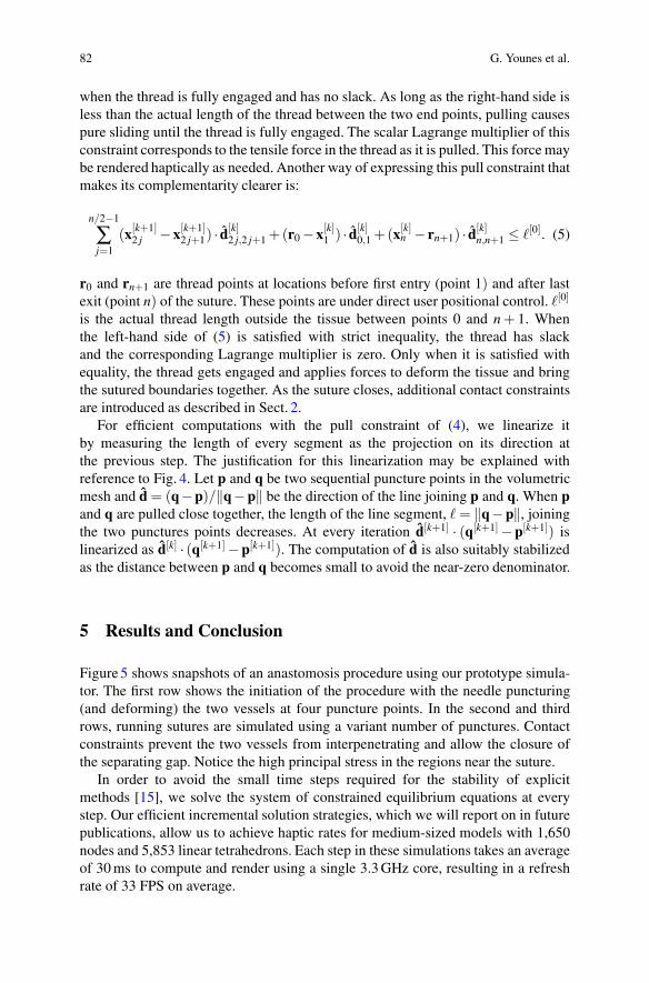
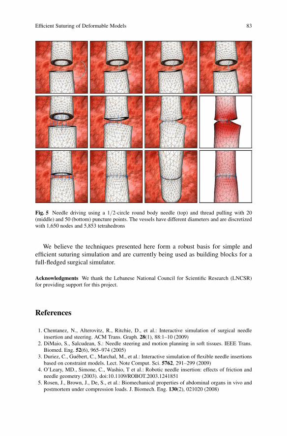
Figure 5 shows snapshots of an anastomosis procedure using our prototype simula-tor. The first row shows the initiation of the procedure with the needle puncturing(and deforming) the two vessels at four puncture points. In the second and thirdrows, running sutures are simulated using a variant number of punctures. Contactconstraints prevent the two vessels from interpenetrating and allow the closure ofthe separating gap. Notice the high principal stress in the regions near the suture.
In order to avoid the small time steps required for the stability of explicitmethods [15], we solve the system of constrained equilibrium equations at everystep. Our efficient incremental solution strategies, which we will report on in futurepublications, allow us to achieve haptic rates for medium-sized models with 1,650nodes and 5,853 linear tetrahedrons. Each step in these simulations takes an averageof 30 ms to compute and render using a single 3.3 GHz core, resulting in a refreshrate of 33 FPS on average.
Efficient Suturing of Deformable Models 83
Fig. 5 Needle driving using a 1/2-circle round body needle (top) and thread pulling with 20(middle) and 50 (bottom) puncture points. The vessels have different diameters and are discretizedwith 1,650 nodes and 5,853 tetrahedrons
We believe the techniques presented here form a robust basis for simple andefficient suturing simulation and are currently being used as building blocks for afull-fledged surgical simulator.
Acknowledgments We thank the Lebanese National Council for Scientific Research (LNCSR)for providing support for this project.
References
1. Chentanez, N., Alterovitz, R., Ritchie, D., et al.: Interactive simulation of surgical needleinsertion and steering. ACM Trans. Graph. 28(1), 88:1–10 (2009)
2. DiMaio, S., Salcudean, S.: Needle steering and motion planning in soft tissues. IEEE Trans.Biomed. Eng. 52(6), 965–974 (2005)
3. Duriez, C., Guebert, C., Marchal, M., et al.: Interactive simulation of flexible needle insertionsbased on constraint models. Lect. Note Comput. Sci. 5762, 291–299 (2009)
4. O’Leary, MD., Simone, C., Washio, T et al.: Robotic needle insertion: effects of friction andneedle geometry (2003). doi:10.1109/ROBOT.2003.1241851
5. Rosen, J., Brown, J., De, S., et al.: Biomechanical properties of abdominal organs in vivo andpostmortem under compression loads. J. Biomech. Eng. 130(2), 021020 (2008)
84 G. Younes et al.
6. Laycock, S., Day, A.: A survey of haptic rendering techniques. Comput. Graph. Forum 56(1),50–65 (2007)
7. Guebert, C., Duriez, C., Cotin, S., et al.: Suturing simulation based on complementarityconstraints. Proc. SCA (Poster) (2009)
8. Otaduy, M.A., Tamstorf, R., Steinemann, D., et al.: Implicit contact handling for deformableobjects. Comput. Graph. Forum 28(2), 559–568 (2009)
9. Tang, M., Manocha, D., Tong, R.: Fast continuous collision detection using deforming non-penetration filters (2010). doi:10.1145/1730804.1730806
10. Teschner, M., Kimmerle, S., Heidelberger, B., et al.: Collision detection for deformable objects.Comput. Graph. Forum 24(1), 61–81 (2005)
11. Berkley, J., Turkiyyah, G., Berg, D., et al.: Real-time finite element modeling for surgerysimulation: an application to virtual suturing. IEEE Trans. Vis. Comput. Graph. 10(3), 314–325 (2004)
12. Lenoir, J., Meseure, P., Grisoni, L.: A suture model for surgical simulation. Lect. NotesComput. Sci. 3078, 105–113 (2004)
13. Wittek, A., Dutta-Roy, T., Taylor, Z., et al.: Subject-specific non-linear biomechanical modelof needle insertion into brain. Comput. Meth. Biomech. Biomed. Eng. 11(2), 135–146 (2008)
14. Choi, K.S., Chan, S.H., Pang, W.M.: Virtual suturing simulation based on commodity physicsengine for medical learning. J. Med. Syst. 36(3), 1781–1793 (2012)
15. Miller, K., Joldes, G., Lance, D., et al.: Total Lagrangian explicit dynamics finite elementalgorithm for computing soft tissue deformation. Comm. Numer. Meth. Eng. 23(2), 121–134(2007)