Embed Size (px)
Citation preview
COMPARISON OF THE MECHANICAL AND SURFACE PROPERTIES OF RETRIEVED AND UNUSED AESTHETIC ORTHODONTIC ARCHWIRES
BY
JENNY FLANAGAN
A thesis submitted to the University of Birmingham for the degree of
MASTER OF PHILOSOPHY
School of Dentistry St. Chads Queensway
Birmingham B4 6NN
August 2015
University of Birmingham Research Archive
e-theses repository This unpublished thesis/dissertation is copyright of the author and/or third parties. The intellectual property rights of the author or third parties in respect of this work are as defined by The Copyright Designs and Patents Act 1988 or as modified by any successor legislation. Any use made of information contained in this thesis/dissertation must be in accordance with that legislation and must be properly acknowledged. Further distribution or reproduction in any format is prohibited without the permission of the copyright holder.
Acknowledgements
I would like to thank the following people for their assistance in the completion of this thesis: My academic supervisor Professor Owen Addison for his unending guidance, advice, assistance, patience and time. My clinical supervisor Mrs Shanthi Sidhom for her help and guidance. The staff and patients of the Orthodontic Units of the Birmingham Dental Hospital and the Worcester Royal Hospital for participating in this study. .
Abstract The appearance of orthodontic appliances has been improved by the introduction of tooth
coloured brackets. Aesthetic archwires are highly desirable to complement aesthetic brackets
in clinical orthodontics. The objective of this study was to characterise the elastic behaviour
of aesthetic archwires and determine whether their behaviour was modified following intra-
oral use. The load-deflection behaviour of five types of coated and uncoated 0.014” NiTi
archwires in their as-supplied condition and following 6 weeks of intra-oral use was
characterised using 3 point wire bending tests (n=10 per group). Representative archwires
from each group were examined using Scanning Electron Microscopy. The results indicated
that the archwires behaviour after 6 weeks of clinical use was more unpredictable than that of
unused archwires. In addition the retrieved PTFE coated archwires produced lower unloading
forces than unused archwires. The force generated by the uncoated and PTFE coated
archwires was comparable. The coated archwires undergo significant delamination of the
coating after 6 weeks of clinical use. Within the confines of the limitations of this study the
clinical implications are that the PTFE coated archwires moved teeth at comparable rates to
their uncoated counterparts. However the coating did degrade and the archwires behaved less
predictably after 6 weeks of clinical use.
CONTENTS Title Abstract Acknowledgements Contents List of figures…………………………………………………………………………………..I List of tables……….
Chapter 1
1.1 INTRODUCTION ........................................................................................................................ 1
1.2 ORTHODONTIC ARCHWIRES ................................................................................................. 1
1.2.1 Levelling and aligning the arches ......................................................................................... 1
1.2.2 Elastic properties of orthodontic archwires .......................................................................... 2
1.2.3 The use of aligning and working orthodontic archwires in fixed appliance treatment ........ 6
1.2.4 Archwires Materials ............................................................................................................. 8
1.2.4.1 NiTi as an archwire material for levelling and aligning the arches ............................... 8
1.2.4.1.a History and background .......................................................................... 8
1.2.4.1.b Properties of nickel titanium alloys ......................................................... 8
1.2.4.1.c Superelastic NiTi ................................................................................... 12
1.2.4.1.d Thermoelastic NiTi ............................................................................... 13
1.2.4.1.e NiTi Copper Chromium Alloys ............................................................ 13
1.2.4.1 f Clinical effectiveness of NiTi archwires ............................................... 14
1.2.4.2 Beta-titanium archwires .............................................................................................. 14
1.3 AESTHETIC ORTHODONTIC ARCHWIRES ........................................................................ 14
1.3.1 The demand for aesthetic archwires ................................................................................... 14
1.3.2 History ................................................................................................................................ 15
1.3.3 Development of Aesthetic Archwires ................................................................................. 16
1.3.3a Metal-free archwires ........................................................................................ 16
1.3.3b Coated archwires ............................................................................................. 17
1.3.4 Contemporary coated aesthetic archwires .......................................................................... 19
1.4 EVIDENCE FOR THE PERFORMANCE OF AESTHETIC ORTHODONTIC ARCHWIRES
.............................................................................................................................. 19
1.4.1 Mechanical Properties ........................................................................................................ 19
1.4.2 Surface Topography ........................................................................................................... 20
1.4.3 Durability ............................................................................................................................ 21
1.4.4 Fatigue ................................................................................................................................ 22
1.5 ANALYSIS OF RETRIEVED ARCHWIRES – COLLECTION AND MODIFICATION OF PROPERTIES ....................................................................................................... 23
1.6 METHODS OF ASSESSING THE PROPERTIES OF ORTHODONTIC ARCHWIRES ....... 24
1.6.1 Load deflection properties .................................................................................................. 24
1.6.2 Surface Topography ........................................................................................................... 25
1.6.3 Surface Roughness ............................................................................................................. 25
1.6.4 Fatigue ................................................................................................................................ 26
1.6.5 Durability of the coating ..................................................................................................... 26
1.7 AIMS AND OBJECTIVES ........................................................................................................ 27
1.8 NULL HYPOTHESIS ................................................................................................................ 27
Chapter 2 - Materials and Methods
2.1 ETHICAL APPROVAL ............................................................................................................. 28
2.2 ARCHWIRE MATERIALS ....................................................................................................... 28
2.3 PATIENT SELECTION ............................................................................................................. 30
2.4 PLACEMENT AND RETRIEVAL OF ARCHWIRES ............................................................. 30
2.5 DETERMINATION OF FORCE-DISPLACEMENT RELATIONSHIPS OF UNUSED AND RETRIEVED WIRES ........................................................................................... 31
2.5.1 Wire bending tests .............................................................................................................. 31
2.5.2 Scanning Electron Microscopy ........................................................................................... 32
2.5.3 Surface profilometry ........................................................................................................... 33
2.6 STATISTICS .............................................................................................................................. 33
Chapter 3 – Results
3.1 LOAD DEFLECTION BEHAVIOUR OF UNCOATED AND COATED 0.014" NITI ARCHWIRES ....................................................................................................... 34
3.1.1 Load-deflection behaviour of uncoated archwires ............................................................. 34
3.1.2 Load-deflection behaviour aesthetic coated archwires ....................................................... 36
3.2 IMPACT OF CLINICAL USE ON THE LOAD-DEFLECTION BEHAVIOUR OF COATED
AND UNCOATED ARCHWIRES ...................................................................... 39
3.2.1 3M uncoated archwires ....................................................................................................... 39
3.2.2 Euroline labially coated aesthetic archwires ...................................................................... 40
3.2.3 Orthocare fully coated aesthetic archwires ......................................................................... 41
3.2.4 Rhodium coated aesthetic archwires .................................................................................. 41
3.3 LOAD-DEFLECTION BEHAVIOUR OF DIFFERENT AESTHETIC ARCHWIRES ........... 43
3.4 IMPACT OF CLINCIAL USAGE ON MECHANICAL ARCHWIRE PARAMETERS ......... 44
3.4.1 Unused archwires –deflected to 2mm ................................................................................ 44
3.4.2 Retrieved archwires –deflected to 2mm ............................................................................. 44
3.4.3 Unused archwires –deflected to 1mm ................................................................................ 45
3.4.4 Unused archwires –deflected to 1mm ................................................................................ 45
3.5 SURFACE ROUGHNESS RESULTS ....................................................................................... 46
3.6 SEM RESULTS .......................................................................................................................... 47
Chapter 4 - Discussion
4.1 IMPACT OF CLINICAL USE ON THE BEHAVIOUR OF COATED AND UNCOATED ARCHWIRES ....................................................................................................... 53
4.1.1 Load-deflection behaviour .................................................................................................. 53
4.1.2 Engagement and active forces ............................................................................................ 55
4.2 IMPACT OF COATING ON THE BEHAVIOUR OF NICKEL-TITANIUM ARCHWIRES . 57
4.3 SURFACE CHARACTERISTICS OF UNUSED AND RETRIEVED COATED AND COATED ARCHWIRES ...................................................................................... 59
4.4 LIMITATIONS OF THE STUDY .............................................................................................. 61
Chapter 5 – Conclusion
5.1 FUTURE WORK ........................................................................................................................ 64
References ................................................................................................................................ 65 Appendices Appendix 1A - Email to NRES to clarify the need for ethical approval ...................................... 76 Appendix 1B - Email to clarify the need for ethical approval ..................................................... 76
Appendix 1C - Email from NRES confirming that ethical approval is not sought for this research. ................................................................................................................ 77
List of Figures
Figure 1.1 An illustrative plot of the stress-strain relationship of a stainless-steel archwire material under tensile loading demonstrating the elastic region (A), yield point (B), plastic region(C) and failure point (D). Figure 1.2: Idealised stress-strain curve for nickel-titanium wire showing the plateaus that occur during stress-induced phase transformations. Figure 3.1a Mean load and the associated standard deviations (N) required to deflect the 3M uncoated archwires centrally to maximum deflection of 1 mm at a constant loading rate of 1mm/min. Once the peak deflection had been reached the unloading was undertaken at a constant rate of 1mm/min. Figure 3.1b Mean load and the associated standard deviations (N) required to deflect the 3M uncoated archwires centrally to maximum deflection of 2 mm at a constant loading rate of 1mm/min. Once the peak deflection had been reached the unloading was undertaken at a constant rate of 1mm/min. Figure 3.2a Mean load and the associated standard deviations (N) required to deflect the Sentalloy uncoated archwires centrally to maximum deflection of 1 mm at a constant loading rate of 1mm/min. Once the peak deflection had been reached the unloading was undertaken at a constant rate of 1mm/min. Figure 3.2b Mean load and the associated standard deviations (N) required to deflect the Sentalloy uncoated archwires centrally to maximum deflection of 2 mm at a constant loading rate of 1mm/min. Once the peak deflection had been reached the unloading was undertaken at a constant rate of 1mm/min. Figure 3.3a Mean load and the associated standard deviations (N) required to deflect the Euroline labially coated archwires centrally to maximum deflection of 1 mm at a constant loading rate of 1mm/min. Once the peak deflection had been reached the unloading was undertaken at a constant rate of 1mm/min. Figure 3.3b Mean load and the associated standard deviations (N) required to deflect the Euroline labially coated archwires centrally to maximum deflection of 2 mm at a constant loading rate of 1mm/min. Once the peak deflection had been reached the unloading was undertaken at a constant rate of 1mm/min. Figure 3.4a Mean load and the associated standard deviations (N) required to deflect the Orthocare fully coated archwires centrally to maximum deflection of 1 mm at a constant loading rate of 1mm/min. Once the peak deflection had been reached the unloading was undertaken at a constant rate of 1mm/min. Figure 3.4b Mean load and the associated standard deviations (N) required to deflect the Orthocare fully coated archwires centrally to maximum deflection of 2 mm at a constant loading rate of 1mm/min. Once the peak deflection had been reached the unloading was undertaken at a constant rate of 1mm/min.
Figure 3.5a Mean load and the associated standard deviations (N) required to deflect the Rhodium coated archwires centrally to maximum deflection of 1 mm at a constant loading rate of 1mm/min. Once the peak deflection had been reached the unloading was undertaken at a constant rate of 1mm/min. Figure 3.5b Mean load and the associated standard deviations (N) required to deflect the Rhodium coated archwires centrally to maximum deflection of 2 mm at a constant loading rate of 1mm/min. Once the peak deflection had been reached the unloading was undertaken at a constant rate of 1mm/min. Figure 3.6a Mean load and the associated standard deviations (N) required to deflect the 3M retrieved uncoated archwires centrally to maximum deflection of 1 mm at a constant loading rate of 1mm/min. Once the peak deflection had been reached the unloading was undertaken at a constant rate of 1mm/min. Figure 3.6b Mean load and the associated standard deviations (N) required to deflect the 3M rerieved uncoated archwires centrally to maximum deflection of 2 mm at a constant loading rate of 1mm/min. Once the peak deflection had been reached the unloading was undertaken at a constant rate of 1mm/min. Figure 3.6c Mean load and the associated standard deviations (N) required to deflect the unused 3M uncoated archwires centrally to maximum deflection of 1 mm at a constant loading rate of 1mm/min. Once the peak deflection had been reached the unloading was undertaken at a constant rate of 1mm/min. Figure 3.6d Mean load and the associated standard deviations (N) required to deflect the unused 3M uncoated archwires centrally to maximum deflection of 2 mm at a constant loading rate of 1mm/min. Once the peak deflection had been reached the unloading was undertaken at a constant rate of 1mm/min. Figure 3.7a Mean load and the associated standard deviations (N) required to deflect the retrieved Euroline labially coated archwires centrally to maximum deflection of 1 mm at a constant loading rate of 1mm/min. Once the peak deflection had been reached the unloading was undertaken at a constant rate of 1mm/min. Figure 3.7b Mean load and the associated standard deviations (N) required to deflect the retrieved Euroline labially coated archwires centrally to maximum deflection of 2 mm at a constant loading rate of 1mm/min. Once the peak deflection had been reached the unloading was undertaken at a constant rate of 1mm/min. Figure 3.7c Mean load and the associated standard deviations (N) required to deflect the unused Euroline labially coated archwires centrally to maximum deflection of 1 mm at a constant loading rate of 1mm/min. Once the peak deflection had been reached the unloading was undertaken at a constant rate of 1mm/min. Figure 3.7d Mean load and the associated standard deviations (N) required to deflect the unused Euroline labially coated archwires centrally to maximum deflection of 2 mm at a
constant loading rate of 1mm/min. Once the peak deflection had been reached the unloading was undertaken at a constant rate of 1mm/min. Figure 3.8a Mean load and the associated standard deviations (N) required to deflect the retrieved Orthocare fully coated archwires centrally to maximum deflection of 1 mm at a constant loading rate of 1mm/min. Once the peak deflection had been reached the unloading was undertaken at a constant rate of 1mm/min. Figure 3.8b Mean load and the associated standard deviations (N) required to deflect the retrieved Orthocare fully coated archwires centrally to maximum deflection of 2 mm at a constant loading rate of 1mm/min. Once the peak deflection had been reached the unloading was undertaken at a constant rate of 1mm/min. Figure 3.8c Mean load and the associated standard deviations (N) required to deflect the unused Orthocare fully coated archwires centrally to maximum deflection of 1 mm at a constant loading rate of 1mm/min. Once the peak deflection had been reached the unloading was undertaken at a constant rate of 1mm/min. Figure 3.8d Mean load and the associated standard deviations (N) required to deflect the unused Orthocare fully coated archwires centrally to maximum deflection of 2 mm at a constant loading rate of 1mm/min. Once the peak deflection had been reached the unloading was undertaken at a constant rate of 1mm/min. Figure 3.9a Mean load and the associated standard deviations (N) required to deflect the retrieved Rhodium coated archwires centrally to maximum deflection of 1 mm at a constant loading rate of 1mm/min. Once the peak deflection had been reached the unloading was undertaken at a constant rate of 1mm/min. Figure 3.9b Mean load and the associated standard deviations (N) required to deflect the retrieved Rhodium coated archwires centrally to maximum deflection of 2 mm at a constant loading rate of 1mm/min. Once the peak deflection had been reached the unloading was undertaken at a constant rate of 1mm/min. Figure 3.9c Mean load and the associated standard deviations (N) required to deflect the unused Rhodium coated archwires centrally to maximum deflection of 1 mm at a constant loading rate of 1mm/min. Once the peak deflection had been reached the unloading was undertaken at a constant rate of 1mm/min. Figure 3.9d Mean load and the associated standard deviations (N) required to deflect the unused Rhodium coated archwires centrally to maximum deflection of 2 mm at a constant loading rate of 1mm/min. Once the peak deflection had been reached the unloading was undertaken at a constant rate of 1mm/min. Figure 3.10 Mean load-deflection plots of the Rhodium coated, Euroline partially coated and Orthocare fully coated archwires measured using 3 point bending to a maximum deflection of 2 mm
Figure 3.11 Mean load-deflection plots of the Rhodium coated, Euroline partially coated and Orthocare fully coated archwires measured using 3 point bending to a maximum deflection of 2 mm following retrieval after clinical usage
Figure 3.12a SEM images of a 3M uncoated, unused archwire
Figure 3.12b SEM images of a 3M uncoated retrieved archwire
Figure 3.13a SEM images of a Sentalloy uncoated, unused archwire
Figure 3.14a SEM images of a Euroline labially coated, unused archwire
Figure 3.14b SEM images of a Euroline labially coated, retrieved archwire
Figure 3.15a SEM images of a Orthocare fully coated, unused archwire
Figure 3.15b SEM images of a Orthocare fully coated, retrieved archwire
Figure 3.16a SEM images of a Sentalloy rhodium coated, unused archwire
Figure 3.16a SEM images of a Sentalloy rhodium coated, retrieved archwire
List of Tables
Table 1.1 The physical differences between marsenite and austenite phases. Table 1.2 Physical characteristics of Teflon. Table 3.1 Results obtained for the 3 point wire bending tests carried out at a 2 mm deflection on the unused archwires. It includes the peak loads, the magnitude of the load at 1.5 mm deflection, 1 mm deflection and the loading and unloading gradients. Table 3.2 Results obtained for the 3 point wire bending tests carried out at 2 mm deflection on the retrieved archwires. It includes the peak loads, the load at 1.5 mm deflection, 1 mm deflection and the loading and unloading gradients. Table 3.3 Results obtained for the 3 point wire bending tests carried out on unused archwires at 1 mm deflection. It includes the peak load at 1 mm, the load at 0.5 mm deflection and the loading and unloading gradients. Table 3.4 Results obtained for the 3 point wire bending tests carried out on retrieved archwires at 1 mm deflection. It includes the peak load at 1 mm, the load at 0.5 mm deflection and the loading and unloading gradients. Table 3.5 summarises the mean surface roughness (Ra-value [µm]) for wires as-used and in their unused condition. Sentalloy uncoated was not studied in this experiment for in-vivo use.
1
Chapter 1
1.1 INTRODUCTION
Orthodontic treatment is usually carried out using fixed appliances that are directly attached to
the teeth. The orthodontic brackets, archwires and auxiliary components that make up the
fixed appliance mediate tooth movement by controlled application of forces at the tooth-
bracket interface. The fixed-appliance components which include the brackets and archwires
are routinely manufactured from metals, however there is increasing demand from patients for
more cosmetic ‘less visible’ appliances. As a consequence ‘tooth coloured’ brackets
manufactured from polyurethane, polycabonate and aluminium oxide have been developed,
however the aesthetic outcome remains limited due to the visibility of the metal orthodontic
archwire. Replacement of the metal orthodontic archwire with a ‘tooth coloured’ substrate is
challenging as the mechanical properties of the archwire itself are fundamental to providing
the correct forces to direct orthodontic tooth movement. Accordingly there have been many
attempts to camouflage existing metal archwires with tooth coloured coatings to meet the
patient’s cosmetic demands. The behaviour of these coated archwires in the short term and
during usage has not been fully characterised. The objective of this study was to characterise
the elastic behaviour of aesthetic archwires and determine whether the behaviour was
modified following intra-oral use.
1.2 ORTHODONTIC ARCHWIRES 1.2.1 Levelling and aligning the arches The overall aim of orthodontic treatment is to move teeth into an idealised relationship
described by Andrew’s six keys (Andrews, 1972). The goals of the first phase of orthodontic
treatment are to both align the teeth and to correct vertical discrepancies by levelling out the
2
dental arches. To align the teeth it is necessary to bring malpositioned teeth into the dental
arch; to specify and control the antero-posterior position of incisors; the width of the arches
posteriorly and the form of the dental arches. Levelling of the dental arch can occur by
extrusion of the posterior teeth, by intrusion of the incisors or a combination of both actions
(Profitt et al, 2007).
1.2.2 Elastic properties of orthodontic archwires The elastic behaviour of orthodontic archwires is critical to their function and allows the
reproducible application of light forces to the tooth to initiate or maintain tooth movement
(Kapila and Sachdeva, 1989). The elastic behavior of a material describes its ability to be
reversibly deformed and can be identified by measuring the stress-strain relationship generated
by externally loading the material (Collings, 1984). Stress can be considered as the internal
distribution of the applied load and is defined as force per unit area, measured in Pascal (Pa)
where one Pa is equivalent to one Newton per square metre (N/m2). Strain is the internal
distortion of the material as a response to loading and is defined as the magnitude of
deformation relative to the material’s original geometry. Strain is considered elastic if it
completely reverses when an applied load is removed or plastic where permanent deformation
of the material occurs despite the removal of the external load (Kusy, 1997). As strain is a ratio
of change in length relative to the original length of a material it is dimensionless and expressed
as a percentage.
By studying the stress-strain behaviour of a material it is possible to differentiate the separate
regions of elastic and plastic strain (Figure 1). The elastic region is identified as the linear
portion of the stress-strain curve and its gradient (stress/strain) allows the calculation of the
materials modulus of elasticity or “Young’s modulus” (Pa). The transition from elastic
3
(recoverable) strain and plastic (unrecoverable) strain occurs after the material’s yield point.
In the context of orthodontic archwires this is particularly important as beyond this point the
predictable behaviour of the wire diminishes.
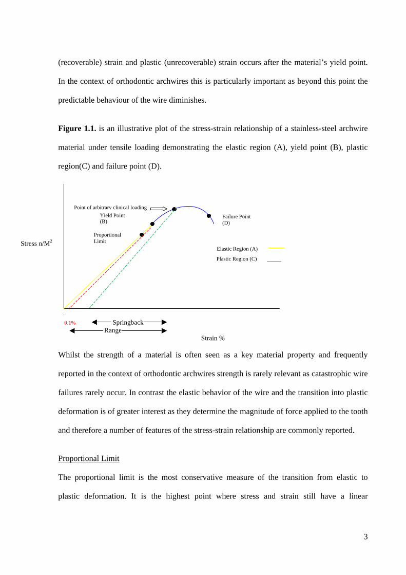
Figure 1.1. is an illustrative plot of the stress-strain relationship of a stainless-steel archwire
material under tensile loading demonstrating the elastic region (A), yield point (B), plastic
region(C) and failure point (D).
Plastic Region (C)
0.1% Springback Range
Strain %
Whilst the strength of a material is often seen as a key material property and frequently
reported in the context of orthodontic archwires strength is rarely relevant as catastrophic wire
failures rarely occur. In contrast the elastic behavior of the wire and the transition into plastic
deformation is of greater interest as they determine the magnitude of force applied to the tooth
and therefore a number of features of the stress-strain relationship are commonly reported.
Proportional Limit
The proportional limit is the most conservative measure of the transition from elastic to
plastic deformation. It is the highest point where stress and strain still have a linear
Stress n/M2
Point of arbitrary clinical loading Yield Point (B)
Proportional Limit
Failure Point (D)
Elastic Region (A)
4
relationship and this relationship is known as Hooke’s law (Ireland and McDonald, 2003). For
the purposes of selecting materials for use as orthodontic archwires it is important to be able
to estimate the proportional limit as it identifies the maximum deflection at which the
archwire will return fully to its original dimension on removal of the load. It is however
extremely difficult to experimentally determine this point precisely.
Yield Strength
The yield strength is a more relevant indicator of the ‘strength’ of a material. It is found as the
intersection of the stress-strain curve with a parallel line offset at 0.1% of the elastic strain
(Ireland and McDonald, 2003). Typically the true elastic limit lies between the proportional
limit and yield strength and both are good estimates of how much force or deflection a wire
can withstand clinically before permanent deformation occurs. Once the archwire becomes
plastically deformed the load it delivers to the teeth is unpredictable.
Stiffness
‘Stiffness’ is a measure of the resistance offered by an elastic body to deformation (bending,
stretching or compression). In the context of orthodontic archwires it is considered as a
measure of its resistance to bending and represents the magnitude of force delivered by the
archwire at a given deflection within its elastic range (Kusy, 1997). ‘Stiffness’ and
‘springiness’ are terms frequently used within clinical orthodontics and have reciprocal
properties where ‘springiness’ = 1/’stiffness’. Each term is proportional to the gradient of the
elastic portion of the force-deflection curve. The more horizontal the slope of the force-
deflection plot is, the springier the wire is, and the more vertical the slope the stiffer the wire.
5
Range and Springback
The range is considered as the distance the wire will bend elastically before permanent
deformation occurs. If the archwire is deflected beyond this point it will not return to its
original shape but can retain clinically useful ‘springback’ unless the failure point is reached
(Kusy, 1997). As orthodontic wires are often deformed beyond their elastic limit in clinical
practice it is often impossible to determine the exact force required to generate a set
deflection. As a consequence springback (the measure of recoverable deformation after the
yield point has been exceeded) is an important property in determining clinical efficacy
(Kusy, 1997).
Resilience
Resilience is the energy storage capacity of the wire and is the integral of the stress-strain
relationship. It is calculated as the area under the stress-strain curve until the proportional
limit is reached. Resilience represents the maximum energy per unit volume that can be stored
in the elastic region and the amount of energy stored in the wire before it is plastically
deformed (Kusy, 1997).
Archwires are presented in different forms and as a generalisable rule the mechanical
properties of the archwire are dependent on the material composition, the wire’s cross-section
and the wire length:
As the cross-section of the wire is increased
• The range decreases proportionally.
• The springiness decreases as a fourth power function.
6
As the length of a wire supported at one end is increased:
• The range increases as a square function.
• The springiness increases as a cubic function.
1.2.3 The use of aligning and working orthodontic archwires in fixed appliance
treatment
Ideally archwires are designed to move teeth by applying light (0.3 - 1.0 N) continuous forces,
although the optimum force magnitude for orthodontic tooth movement has yet to be
identified (Ren et al., 2003). It is however accepted that light forces are required to reduce the
potential for patient discomfort, tissue hyalinization and undermining resorption (Chan and
Darendeliler, 2003). Force application should result in elastic behaviour of the archwire which
is required to be maintained over a period of weeks to months (Miura et al., 1986). Different
elastic behaviour of the archwire is required according to the treatment stage and the desired
tooth movement. As a consequence archwires are fabricated from a range of alloys including
stainless steel, cobalt-chromium, nickel-titanium and beta-titanium (Kusy, 1997). Each alloy
system and subdivision has different elastic properties and characteristics that may be more
appropriate at a particular treatment stage and in contemporary orthodontic practice no single
wire is superior for all of the stages of treatment (Kusy, 1997).
It is currently believed that the initial archwires used early in orthodontic treatment for
alignment should provide light continuous forces of approximately 50 grams force (0.5 N) to
produce the most efficient tooth movement (Ren et al., 2003). In terms of archwire
‘properties’ to enable effective tooth alignment during the initial stages of treatment the
archwire requires:
• Low stiffness so that all or most of the teeth in the arch can be ligated.
7
• Large springback to allow for large deflections of the archwire.
• High stored energy (resilience) so that the archwire returns back to its original shape
as the teeth move.
• Biocompatibility to avoid adverse reactions to the archwire material.
• Low surface friction to allow for quick tooth movement.
Of the archwire materials available, nickel-titanium (NiTi) (with a circular cross-section) and
stainless steel multistrand or coaxial wires meet most of these material requirements.
Typically the alignment wires are used with progressively increasing wire cross-sectional
diameters from 0.012 to 0.018 inches depending on the irregularity associated with the
dentition. The alignment wires are often followed by a short period (2 - 4 months) of use of a
rectangular NiTi archwire to begin torque expression and begin root movement (Cobourne
and Dibiase, 2010).
Once initial alignment has been achieved wires of increasing stiffness are then selected to
complete the levelling of the dentition, overbite reduction and tooth movement along the
archwire. During the later stages of treatment, the process of overbite reduction is completed
and if necessary space closure is carried out using sliding mechanics. The archwire used in
this stage of treatment generally requires:
• High stiffness to allow for sliding of the teeth along the archwire and space closing
mechanics.
• Low stored energy so the wire does not deform under the forces used.
• Biocompatibility avoid adverse reactions to the archwire material.
• Low surface friction to allow for quick tooth movement.
8
• Good joinability to allow auxillaries such as crimpable hooks to be added on to the
archwire.
Rectangular stainless steel wires, known as working archwires, are usually selected at this
treatment stage (Cobourne and Dibiase, 2010).
1.2.4 Archwires Materials
1.2.4.1 NiTi as an archwire material for levelling and aligning the arches
1.2.4.1.a History and background NiTi was the first titanium alloy to be applied as an orthodontic material and its typical
composition is 55% nickel and 45% titanium (Andrease and Hilleman, 1971). In the 1960’s,
the Office of the Navy (USA) was actively studying new types of alloys that exhibited a shape
memory effect (SME) (Buehler et al 1963). A NiTi alloy showed great promise and was
named Nitinol as an acronym for the Nickel-Titanium Naval Ordance Laboratory (Kusy,
1997). The opportunity to use Nitinol in orthodontics was recognised by George Andreasen
and through his efforts the first NiTi archwire was marketed to orthodontists under the same
Nitinol name (Andreasen and Hilleman, 1971). Today there are three classes of commercially
available NiTi wires with different stress-strain relationships: (i) martensitic stable
(conventional alloy), (ii) austenitic active (pseudoelastic) and (iii) martensitic active
(thermoplastic) (Kusy, 1997).
1.2.4.1.b Properties of nickel titanium alloys NiTi alloys have two remarkable properties that make them ideal for use as orthodontic
archwires, namely shape memory and superelasticity (Andreasen and Morrow, 1997). In
common with many alloys NiTi can exist in more than one form or crystal structure and
typically for NiTi a martensitic form exists at low temperatures and an austenite form exists at
9
higher temperatures. The key difference between NiTi and other archwire materials is that a
transformation from a martensitic to austenitic phase can occur at relatively low temperatures
and also can be induced by application of external loading (Miura et al., 1986). The two NiTi
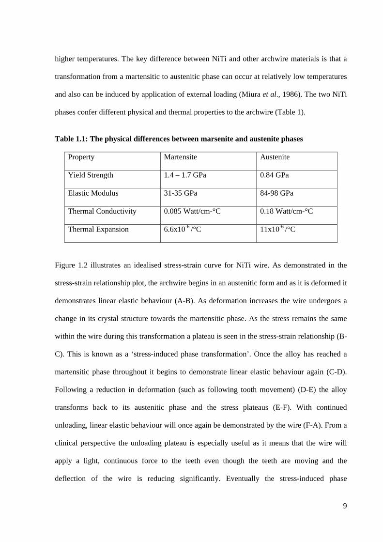
phases confer different physical and thermal properties to the archwire (Table 1).
Table 1.1: The physical differences between marsenite and austenite phases
Property Martensite Austenite
Yield Strength 1.4 – 1.7 GPa 0.84 GPa
Elastic Modulus 31-35 GPa 84-98 GPa
Thermal Conductivity 0.085 Watt/cm-°C 0.18 Watt/cm-°C
Thermal Expansion 6.6x10⁻⁶ /°C 11x10-6 /°C
Figure 1.2 illustrates an idealised stress-strain curve for NiTi wire. As demonstrated in the
stress-strain relationship plot, the archwire begins in an austenitic form and as it is deformed it
demonstrates linear elastic behaviour (A-B). As deformation increases the wire undergoes a
change in its crystal structure towards the martensitic phase. As the stress remains the same
within the wire during this transformation a plateau is seen in the stress-strain relationship (B-
C). This is known as a ‘stress-induced phase transformation’. Once the alloy has reached a
martensitic phase throughout it begins to demonstrate linear elastic behaviour again (C-D).
Following a reduction in deformation (such as following tooth movement) (D-E) the alloy
transforms back to its austenitic phase and the stress plateaus (E-F). With continued
unloading, linear elastic behaviour will once again be demonstrated by the wire (F-A). From a
clinical perspective the unloading plateau is especially useful as it means that the wire will
apply a light, continuous force to the teeth even though the teeth are moving and the
deflection of the wire is reducing significantly. Eventually the stress-induced phase
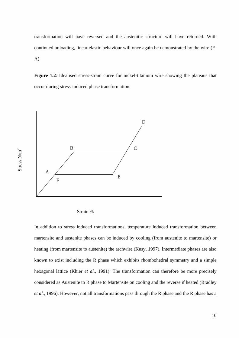
10
transformation will have reversed and the austenitic structure will have returned. With
continued unloading, linear elastic behaviour will once again be demonstrated by the wire (F-
A).
Figure 1.2: Idealised stress-strain curve for nickel-titanium wire showing the plateaus that
occur during stress-induced phase transformation.
In addition to stress induced transformations, temperature induced transformation between
martensite and austenite phases can be induced by cooling (from austenite to martensite) or
heating (from martensite to austenite) the archwire (Kusy, 1997). Intermediate phases are also
known to exist including the R phase which exhibits rhombohedral symmetry and a simple
hexagonal lattice (Khier et al., 1991). The transformation can therefore be more precisely
considered as Austenite to R phase to Martensite on cooling and the reverse if heated (Bradley
et al., 1996). However, not all transformations pass through the R phase and the R phase has a
Strain %
A
B C
D
E F
Stre
ss N
/m2
11
lower elastic modulus than austenite (Bradley et al., 1996). Importantly the shape memory
and super-elasticity of NiTi are related to phase transitions (between the martensitic and
austenitic forms) that occur at a relatively low transition temperature (Profitt et al., 2007) so
that these behaviours can be potentially exploited by temperature changes which intercept
those encountered in the oral environment.
Early wires had their crystalline structure stabilized or fixed in the martensitic form by cold
working and exhibited greater flexibility but no shape memory (Cobourne and Dibiase, 2010).
Shape memory refers to the ability of the material to ‘remember’ its original shape after
plastic deformation has occurred and in NiTi this remarkable property occurs whilst the
material is in a martensitic phase. The deformation is set while the alloy is maintained at an
elevated temperature that is above the martensite-austenite transition temperature. When the
alloy is then cooled below the transition temperature it can be plastically deformed but when
it is heated again the original shape is restored.
As an orthodontic archwire material Nitinol has a low stiffness and delivers only one-fifth to
one-sixth the force per unit of deactivation when compared with an equivalent dimension
stainless steel wire (Kusy 1997). In addition the strain that can be applied to the wire before it
reaches its yield strength is much greater than for stainless steel. As a consequence
functionally when compared with steel, NiTi archwires of equivalent size can move a tooth
with a lighter force and for a longer period of time. However a limitation of NiTi is its lack of
formability (Ireland and McDonald, 2003).
12
1.2.4.1.c Superelastic NiTi Superelastic NiTi is an active NiTi archwire. On loading the austenitic active alloy starts with
stiffness that produces three times the force per activation of the conventional martensitic
stabilized alloy (Miura et al., 1986). The effect is short-lived and the stress within the wire
then plateaus due to a stress-induced phase transformation which occurs from the austenitic to
the martensitic form. Upon deactivation (reduction in loading) the martensitic phase gradually
transforms back to the austenitic phase and the stress-strain behaviour is typically seen as a
rapid drop in stress (associated with unloading) followed by a plateau at low magnitude of
stress as the deformation reverses (Miura et al., 1986). When the transformation is complete
the stress-strain behaviour of the wire returns to the original behaviour. An orthodontist can
exploit this behaviour to align the teeth provided the archwire is activated within the plateau
region. The term superelasticity is often used interchangeably in the context of NiTi with the
term pseudoelasticity which refers to the second plateau region in which the martensite
reversibly transforms to the austenite form and allows low magnitude forces to be maintained
(Kusy, 1997).
As stated previously the forces generated in NiTi wires are sensitive to temperature. Filleul
and Jordan, (1997) tested four superelastic archwires and reported that three out of the four of
the wires showed superelasticity at 22°C, two out the four at 39°C and none of the four at
44°C. The origin of the superelastic plateau was also observed to start at different force levels
according to the temperature and lower temperatures were demonstrated to generate a plateau
at a lower force (Nakano et al., 1999; Gurgel et al., 2001). Importantly Bolender et al., (2010)
suggested that most NiTi archwires do not exhibit the same superelastic behaviour in torsion
as traditionally described in flexure (bending) which has clear consequences in the context of
orthodontic alignment.
13
1.2.4.1.d Thermoelastic NiTi Thermoelastic NiTi wires exhibit a thermally induced shape memory effect. A stress induced
phase transformation of the alloy’s crystal structure occurs at a temperature range referred to
as the temperature transition range (TTR) (Miura et al., 1986). The wire exists in a martensitic
phase below the TTR and can therefore be deformed and very easily to be ligated to a
severely malpositioned tooth. As the wire heats up a phase transformation occurs to the
austenitic phase and the archwire effectively becomes stiffer increasing the load (force) on the
tooth and encouraging it to move. The wire has a temperature transition range similar to
mouth temperature (35 °C) and hence after ligation and thermal equilibration in the mouth the
phase transformation begins. Typically the wire is cooled to facilitate insertion into the
brackets of misplaced teeth before undergoing the aforementioned phase transformation and
applying force to the teeth through this shape memory effect (Kapila and Sachdeva, 1989).
1.2.4.1.e NiTi Copper Chromium Alloys The addition of copper to NiTi alloys has been shown to increase strength, reduce hysteresis
and allows greater precision in the setting of the austenitic transformation temperature (Gil
and Planell, 1995)). The addition of copper also increases the transformation temperature to
above that of the oral cavity and therefore requires the addition of 0.2 to 0.5% chromium to
reduce the transformation temperature back to a functionally useful range. Originally CuNiTi
wires were produced with four different austenitic transformation temperatures (TT) covering
both superelastic and thermoelastic archwires: TT Type 1 15°C, Type 2 27°C, Type 3 35°C
and Type 4 had a TT of 40°C. A study by Pandis et al., (2009) comparing 0.016” 35° CuNiTi
and 0.016” NiTi archwires found no difference in the resolution of mandibular anterior
crowding between the two groups.
14
1.2.4.1.f Clinical effectiveness of NiTi archwires Numerous studies have attempted to establish the clinical effectiveness of NiTi wires
compared with other initial aligning archwires but no studies to date have clearly identified
the supposed benefits (O’Brien et al, 1990; West et al, 1995; Evans et al, 1998). It has been
postulated that the wires only behave in a superelastic manner when they are subjected to
large deflections and this may be why previous studies have failed to establish their
superiority in the initial stages of alignment.
1.2.4.2 Beta-titanium archwires Beta-titanium archwires are also in clinical use a typical composition is 80% titanium, 10%
molybdenum, 6% zirconium and 4% tin (Kusy,1997)). Beta-titanium has an advantage over
NiTi possessing good formability however the stiffness is roughly one-third that of stainless
steel and half that of NiTi (Burstone and Goldberg, 1980). In addition beta-titanium archwires
are also associated with higher friction and undergo smaller levels of permanent deformation.
They are often used in the final stages of treatment, when finishing bends may be required to
detail individual tooth position and achieve settling of the occlusion (Profitt et al., 2007).
1.3 AESTHETIC ORTHODONTIC ARCHWIRES
1.3.1 The demand for aesthetic archwires
The demand for aesthetic orthodontic appliances is increasing and the aesthetics of
orthodontic appliances has improved significantly with the use of transparent brackets
fabricated from ceramic or composite materials (Russell, 2005). Other approaches for
aesthetic orthodontic treatment include aligners and lingual appliances (Lagravere and Flores-
Mir, 2005; Poon and Taverne, 1998; LY, Kula K, 2006). A recent study by Feu et al., (2012)
found that clear aligners were considered to be the best aesthetic option by adults, followed by
15
the combination of sapphire (aluminium oxide) brackets and aesthetic archwires. The demand
for aesthetic appliances is driven by the increased number of adults seeking orthodontic
treatment. Aesthetic archwires are highly desirable to complement aesthetic brackets in
clinical orthodontics.
1.3.2 History
A number of alternatives to metal have been explored to create an aesthetic archwire that
would allow efficient orthodontic treatment with the appliance visible labially (Russell,
2005). Archwires and in particular NiTi have been coated in tooth coloured polymers or
inorganic materials. Deficiencies with coated archwires include the fact that the coating is
frequently reported to peel or wear and it can be difficult to bend the wire (Neumann et al.,
2002). The extent of the coating is limited by the small cross sections needed for orthodontic
wires. In addition since the outer surfaces of the archwire are most distant from the neutral
axis they are biomechanically the most important and should therefore have optimal
properties and hence placement of a coating may affect archwire efficacy.
Polymeric composite wires have been in development since the early 1990s. Their advantage
over coated wires is their transparency and their capability to vary the stiffness of the wire
without changing its cross-sectional profile (Burstone, 1981). There is a debatable concern
regarding metallic alloys and allergic reactions to nickel (Jones et al., 1986). Some authors
have found no effect on patients, others described a sensitization of the patients by the use of
nickel containing materials and several authors reported cases of allergic reactions to nickel
containing orthodontic devices and advise the use of nickel free devices for the treatment of
patients already sensitized to nickel (Vreeburg et al., 1990; Kusy et al., 1998). This problem
could be avoided with composite materials (Jones et al., 1986). The problems associated with
16
polymeric archwires are that although they have many of the properties necessary for an
orthodontic archwire they have insufficient rigidity and strength.
1.3.3 Development of Aesthetic Archwires
1.3.3a Metal-free archwires
There have been considerable efforts to develop totally metal-free alternatives to currently
available metallic archwires. The first aesthetic non metallic orthodontic wire, Optifelx,
contained a silica dioxide core that provided the force to move the teeth, a silicone resin
middle layer that protected the core from moisture and a stain-resistant nylon outer layer
which serves the dual purpose of preventing damage to the archwire and further increasing the
strength of the archwire (Talass, 1992). Advantages of this wire include very good aesthetics
and it’s resistance to stains however it is brittle and sharp bends may result in fracture of the
glass (SiO2) core. It has been characterised as possessing poor springback and thus its clinical
efficacy and ability to be used in a variety of cases has been questioned (Lim et al., 1994).
Subsequently an archwire with S2 glass fibres embedded in a polymeric matrix formed from
bisphenol A-diglycidylether methacrylate and triethylene glycol dimethacrylate was
developed by Fallis and Kusy (Fallis and Kusy, 2000). Other research groups have developed
different fibre reinforced polymer wires however although the appearance of the wires is
excellent clinical uptake has been poor because of their brittle nature (Zufall and Kusy, 2000).
They are also very strong and the stiffness can vary from that of the most flaccid multi-
stranded archwire to nearly that approaching the properties of a beta-titanium archwire.
Mechanical tests show that these archwires are elastic until failure occurs and resilience and
springback are comparable with NiTi (Fallis and Kusy, 2000). When the wire fails, it loses its
stiffness but remains intact. As composites are displacing metallic alloys as structural
17
components in the aerospace industry, the expectation is that the attractive properties and
characteristics of these materials will capture a significant share of the marketplace in the
future.
Recently Burstone described a polymer archwire that had polyphenylene polymer extruded
into it (Burstone et al., 2011). Polyphenylene enhances rigidity, strength and hardness as well
as increasing resistance to stress relaxation. The resultant wire delivered forces generally
similar to typical beta-titanium and NiTi wires of somewhat smaller cross sections. The
magnitude of force the wire produced was similar to that of an aligning or levelling wire. This
wire could serve as a potential aesthetic archwire in the future but further research is needed
(Burstone et al., 2011).
1.3.3b Coated archwires The inability to match the mechanical properties of metallic archwires using non-metal
alternatives has resulted in the development of coated archwires which provide a compromise
allowing some cosmetic improvement whilst aiming to maintain the desirable mechanical
properties of the metallic archwire.
Teflon coated archwires
An obvious materials development to improve the aesthetics of metallic archwires whilst
retaining the functionality includes the application of cosmetic surface coatings. The most
common commercially available coated archwires use polytetrafluroethylene (PTFE) –a
material which has numerous applications in medicine and dentistry (Chiapasco, 1999). PTFE
(Teflon) has also been advocated as a material to be used to improve the anti-cariogenic
properties of composite resins (Gyo et al., 2008), coatings of metallic stents for palliation of
malignant biliary disease (Hatzidakis et al., 2007), artificial muscles and as a conduit for
18
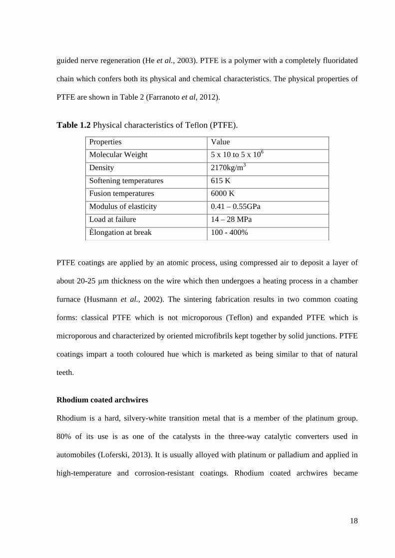
guided nerve regeneration (He et al., 2003). PTFE is a polymer with a completely fluoridated
chain which confers both its physical and chemical characteristics. The physical properties of
PTFE are shown in Table 2 (Farranoto et al, 2012).
Table 1.2 Physical characteristics of Teflon (PTFE).
PTFE coatings are applied by an atomic process, using compressed air to deposit a layer of
about 20-25 µm thickness on the wire which then undergoes a heating process in a chamber
furnace (Husmann et al., 2002). The sintering fabrication results in two common coating
forms: classical PTFE which is not microporous (Teflon) and expanded PTFE which is
microporous and characterized by oriented microfibrils kept together by solid junctions. PTFE
coatings impart a tooth coloured hue which is marketed as being similar to that of natural
teeth.
Rhodium coated archwires
Rhodium is a hard, silvery-white transition metal that is a member of the platinum group.
80% of its use is as one of the catalysts in the three-way catalytic converters used in
automobiles (Loferski, 2013). It is usually alloyed with platinum or palladium and applied in
high-temperature and corrosion-resistant coatings. Rhodium coated archwires became
Properties Value Molecular Weight 5 x 10 to 5 x 10⁶ Density 2170kg/m3 Softening temperatures 615 K Fusion temperatures 6000 K Modulus of elasticity 0.41 – 0.55GPa Load at failure 14 – 28 MPa Èlongation at break 100 - 400%
19
available for commercial use in 2008. These wires have low reflectivity which is promoted as
conferring reduced visibility and improved aesthetics.
1.3.4 Contemporary coated aesthetic archwires
PTFE coated archwires are currently available in thicknesses that range from 0.5 mm to 0.02
mm and come fully coated or with a layer of coating on the labial surface only. They are also
available with a layer of coating just on the anterior segment of the archwire. Sentalloy and
Bioforce (Dentsply GAC, Canada) high aesthetic rhodium coated superelastic archwires are
available with a 0.127 mm rhodium coating.
In 2011 a new aesthetic archwire called Woowa was introduced with a currently
compositionally undeclared polymer coating that is 0.000127 mm thick and tooth-coloured
(Iijima et al., 2012). It is reported as having a double layered coating structure, the inner layer
is silver and platinum and the outer layer is polymeric. The concept is that the outer layer
imparts durability and wear resistance and the inner layer gives the archwires its tooth-
coloured appearance. It is available as a coating on both NiTi and stainless steel archwires.
1.4 EVIDENCE FOR THE PERFORMANCE OF AESTHETIC ORTHODONTIC
ARCHWIRES
1.4.1 Mechanical Properties
Loading and unloading forces produced by PTFE coated archwires have been reported to be
lower than uncoated archwires (Bradley et al, 2013; Alavi and Hosseini, 2012; Iijima et al,
2012; Kaphoor et al, 2011; Elayyan et al, 2010; Elayyan et al, 2008). This may be due to
reduced diameter of the NiTi wires occupying the inner core of the aesthetic wires. A more
recent study did however find that four out of the eleven coated archwires tested, exhibited
20
similar unloading force values when compared with their uncoated counterparts (Washington
et al., 2014). Although lower unloading forces may be desirable, they may not be effective if
it is below the optimum range for orthodontic tooth movement. Clinicians may need larger
wires to get the equivalent force value which increases friction. Friction between the wire,
bracket and ligature may also be important in determining the amount of force delivered by
the wire and as the deflection increases so the angle of emergence of the wire from the bracket
becomes more acute. This increased friction reduces unloading and increases loading forces
and is likely to lead to more damage to the coating.
Elayyan et al., (2008) found that the unloading forces generated by retrieved epoxy resin-
coated archwires with conventional ligation that have been used in vivo for 4 – 6 weeks are
lower than as-received coated archwires. In contrast a more recent study by Bradley et al
(2013) found that retrieved coated archwires produced higher unloading forces when
compared to as-received archwires. They attributed this to the fact that as the coating was lost
the wires behaved more like their uncoated couterparts. When self-ligating brackets are used,
the force value for retrieved archwires is the same as the as-received coated archwires. This
may occur because the self-ligating brackets have reduced friction and are therefore not as
affected by the delamination and increased friction of the retrieved archwires.
1.4.2 Surface Topography
Coated archwires have been shown to have greater surface roughness than uncoated archwires
(Doshi and Wasundhara, 2011; Zufall and Kusy, 2000). Mixed results have been reported
about the relationship between surface roughness and friction. Some studies demonstrated that
there was a positive correlation between surface roughness and frictional resistance, however
other studies reported there is little correlation between surface roughness and friction
21
(Saunders and Kusy, 1994; Doshi and Wasundhara, 2011; Farronato et al., 2012). The coating
layers might influence the frictional characteristics of coated wires but further research is
needed to prove this hypothesis.
Retrieved NiTi archwires have been found to be covered with islands of amorphous
precipitants and accumulated microcrystalline particles. The wires have a proteinaceous
biofilm whose organic constituents are mainly amide, alcohol and carbonate. Elemental
species precipitate on the material surface and include NA, K, Cl, Ca and P, forming NaCl,
KCL and Ca-P precipitates. Porosity and size pore of the wire surface also increases
(Grimsdottir and Hensten-Petersen, 1997).
Coated archwires demonstrate rougher surfaces after use in vivo compared with as received
archwires (Rongo et al., 2013; Wichelhaus et al., 2005; Neumann et al., 2002) which may be
due to the coarse influence of tooth brushing and the interplay of the archwire coating and
bracket edges. Imprints of brackets and areas of degradation have been found in areas related
to the positions of the brackets, and these surface defects may hinder the archwire sliding
through the bracket (Neumann et al., 2002).
1.4.3 Durability
It is noted that coatings on aesthetic archwires had a tendency to split and peel off during use
(Proffit, 2000). Elayyan et al., (2008) found that retrieved PTFE coated archwires suffered
from inconsistent amounts of deterioration after a mean of 33 days in vivo. Many of the
retrieved specimens were characterized by delamination of the coating over large areas.
Although the coating remained intact in some areas, it showed a rougher, discoloured and
deteriorated surface when compared with unused archwires. In total 75% of the PTFE coating
remained on the archwires which is likely to affect the aesthetic value of these aesthetic
22
archwires (Elayyan et al., 2008). Similar results have been reported in more recent studies
with common objectives (Bradley et al, 2013; Da Silva et al, 2013; Alavi and Hosseini,
2012).
Aesthetic archwires can be discoloured by external sources such as food dyes and coloured
mouth rinses. The extent of discolouration depends on the type of coating material and its
surface roughness, the level of oral hygiene and water absorption (Faltermeier et al., 2008).
Da Silva et al., (2013) assessed the colour stability of six aesthetic archwires at different time
periods using a staining coffee solution. The investigators found that all the aesthetic
archwires showed clinically noticeable colour change after 21 days in the staining solution.
The fibre-reinforced metal-free Optis archwire had the most colour alteration, followed by the
coated NiTi and stainless steel archwires (Da Silva et al., 2013).
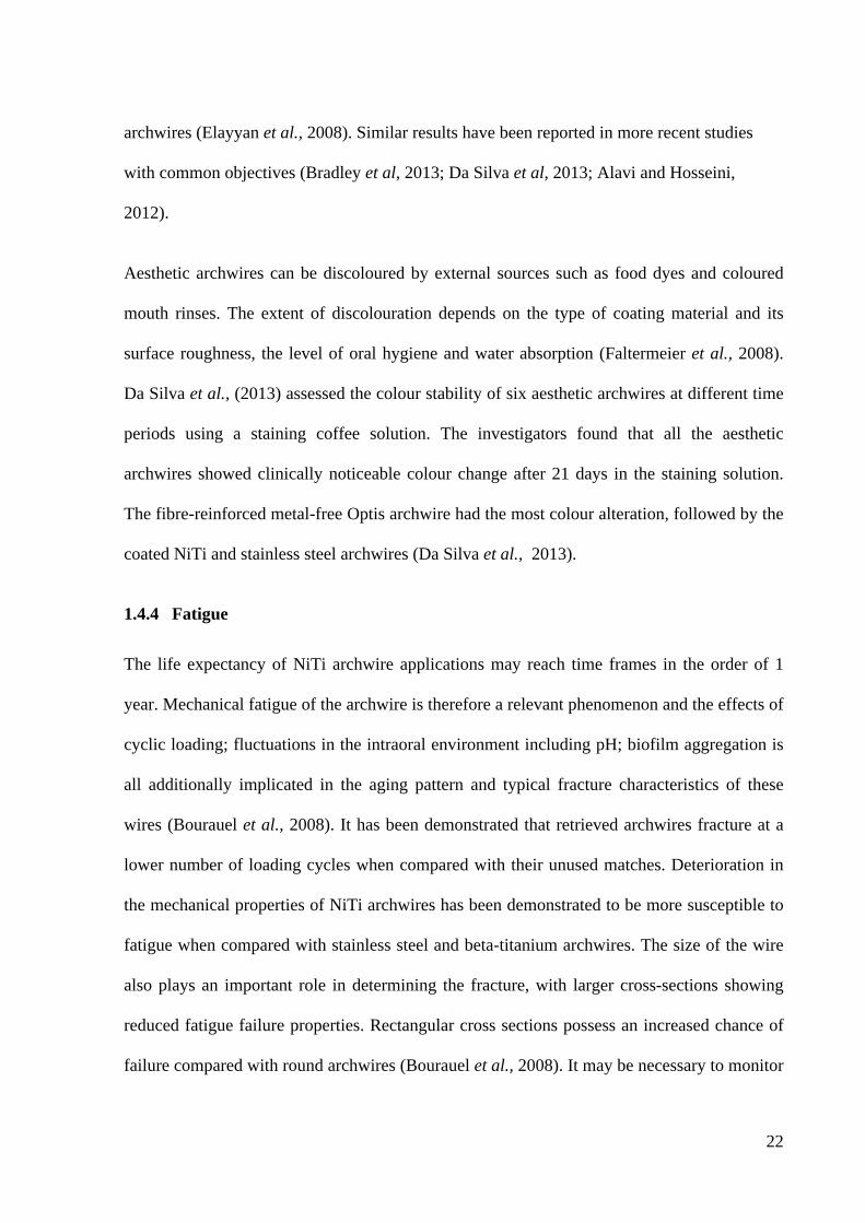
1.4.4 Fatigue
The life expectancy of NiTi archwire applications may reach time frames in the order of 1
year. Mechanical fatigue of the archwire is therefore a relevant phenomenon and the effects of
cyclic loading; fluctuations in the intraoral environment including pH; biofilm aggregation is
all additionally implicated in the aging pattern and typical fracture characteristics of these
wires (Bourauel et al., 2008). It has been demonstrated that retrieved archwires fracture at a
lower number of loading cycles when compared with their unused matches. Deterioration in
the mechanical properties of NiTi archwires has been demonstrated to be more susceptible to
fatigue when compared with stainless steel and beta-titanium archwires. The size of the wire
also plays an important role in determining the fracture, with larger cross-sections showing
reduced fatigue failure properties. Rectangular cross sections possess an increased chance of
failure compared with round archwires (Bourauel et al., 2008). It may be necessary to monitor
23
patients to recognize orthodontic wire failures despite the commonly deployed practice of
increased time between appointments in patients treated using NiTi archwires.
1.5 ANALYSIS OF RETRIEVED ARCHWIRES – COLLECTION AND
MODIFICATION OF PROPERTIES Retrieval analysis has been used for a number of years in the orthopaedic application of
biomaterials. It was first described by Rostoker et al., in 1978 who examined polyethylene
components of hip and knee joint prostheses removed from patients. Due to increasing
interest and the high number of published studies concerning retrieved orthopaedic materials,
standards for the retrieval analysis of orthopaedic materials have been developed.
(International Standards Organization/Draft International Standards, 1996; American Society
for the Testing of Materials, 1997) however to date no ISO or ASTM standardisation exists
for similar objectives in dentistry.
Failure analysis is however gaining popularity in dental materials science due to the
significant information resulting from examining the performance of the material in the
environment in which it functions (Eliades et al., 2000; Bourauel et al., 2008; Daems et al.,
2009; Zegan et al., 2012; Bradley et al., 2014)). It is useful in establishing the effects of intra-
oral aging on the behaviour of orthodontic archwires. Intra-oral use may affect the properties
of archwires such as superelasticity, fracture resistance, force delivery and friction. This
method has also gathered previously undescibed information, such as the assault of specific
microbes on orthodontic materials (Matasa, 1995). One disadvantage of these retrieval studies
is the absence of sequential description of the changes that were induced and the failure to
gather quantitative data.
24
1.6 METHODS OF ASSESSING THE PROPERTIES OF ORTHODONTIC
ARCHWIRES
There are many tests available to assess the mechanical and physical properties of archwires.
Although these tests do not necessarily reflect the clinical situation to which wires are usually
subjected, they provide a basis for comparison of these properties.
1.6.1 Load deflection properties
Springback can be referred to as maximum elastic deflection, maximum flexibility, range of
activation, range of deflection or the working range. It is related to the ratio of yield strength
to the modulus of elasticity of the material. Higher springback values provide the ability to
apply large activations with a resultant increase in working time of the appliance. This implies
that fewer archwire changes will be needed. The load deflection rate is the force magnitude
delivered by an appliance and is proportional to the modulus of elasticity. Low stiffness or
load deflection rates allow lower forces to be applied, a more constant force over time and the
appliance experiences deactivation and greater ease and accuracy in applying a given force
(Kapila and Sachderva, 1989). The load deflection properties are measured using three-point
wire bending tests that were first described by Miura et al. in 1986. The test was designed to
demonstrate the difference between the first nitinol wire and the superelastic nickel-titanium
archwire. This is thought to be the most significant parameter when determining the biologic
nature of orthodontic tooth movement (Krishnan and Kumar, 2004). It provides information
on the behaviour of the wires when exposed to both horizontal and vertical deflections
(Kapila and Sachderva, 1989). This test offers a high degree of reproducibility which enables
comparison between studies (Wilkinson et al., 2002). Other advantages include its close
simulation to clinical application and the capacity to distinguish wires with superelastic
properties. The orthodontic wire is deflected and the generated load is measured. The load-
25
deflection curve generated is analysed to detect the mechanical properties of the archwires. A
fixture between two supports at a pre-determined distance is used. The wire specimen is
secured on orthodontic brackets fixed on the poles using elastomeric ligatures and the testing
is done using a Universal Testing Machine (UTM). A loading platern is attached to the cross
–head of the UTM and the wire is centrally deflected at a fixed deflection rate (most
commonly 1mm/min). The loading and unloading values are then recorded at specific
deflections. The loading curve represents the force needed to engage the wire in the bracket,
whereas the unloading curve represents the forces delivered to teeth.
1.6.2 Surface Topography
The surface topography of orthodontic archwires can be studied with high resolution,
microscopy. Scanning Electron Microscopy (SEM) is a type of electron microscope that
images a sample by scanning it with a beam of electrons in a raster scan pattern. The electrons
interact with the atoms that make up the sample producing signals that contain information
about the sample's surface topography, composition and other properties such as electrical
conductivity. The images are typically qualitatively assessed although image analysis
protocols may enable quantifiable data to be generated.
1.6.3 Surface Roughness
A surface profilometer is a measuring instrument which is used to quantify the features of a
surface topology. A diamond stylus (or non contact guage such as a laser of white light
interferometer) is positioned over the sample and moved laterally for a specified distance
(with a specified contact force for contact methods). Profilometry methods can measure small
surface variations in the vertical access as a function of position, ranging from nanometers to
millimetres depending on the specific guage resolution. Common quantification parameters of
26
surface roughness include the Ra-value which is a mesure of the “roughness” of the surface
and is defined as “the arithmetic mean deviation of the roughness profile from the mean line”.
1.6.4 Fatigue
The fracture resistance of orthodontic archwires can be measured by subjecting the archwire
specimen to cyclic mechanical loading in a set-up that simulates intraoral loading at
deflections of predetermined amounts. The test is performed at 37°C in doubly distilled,
sterile water. The specimen of wire is loaded in a three point bending mode and is fixed at one
end only. The other end can move freely and no additional tensile stress to bending
deformation is applied. The loading frequency is usually set to 1 or 2Hz and cyclic loading is
applied either until fatigue fracture or until a maximum number of loading cycles of 2×10⁶ is
reached (Bourauel et al., 2008).
1.6.5 Durability of the coating
Ellayan described a method of measuring the amount of coating remaining on the archwire
after use using photography. Digital photographs of each side of the wire are taken with the
camera fixed on a tripod and oriented at 90° to the surface on which the archwire is placed.
The distance from the camera to the wire remains constant and a ruler is placed adjacent to the
archwire for calibration purposes. Images are then recorded of the gingival and occlusal
aspects of the archwire and transferred to a computer where the Image J program is used for
analysis. This programme is first calibrated using the ruler in the photograph and the overall
length of the wire and the length of the remaining coated segments is measured. These
measurements are exported to Excel and the percentage of the remaining coating is calculated
by dividing the sum of the length of the remaining coated segments over the overall length of
27
the wire. The average percentage of the two sides of each wire is then calculated (Elayyan et
al., 2008).
1.7 AIMS AND OBJECTIVES
The aim of this study is to assess the mechanical and surface properties of coated archwires
before and after clinical use. The specific objectives of this study are to:
1. Determine the force-displacement relationship of unused 0.014” coated nickel
titanium archwires through 3 point wire bending tests
2. Determine the force-displacement relationship of 0.014” coated nickel titanium
archwires after 6 weeks of clinical use through 3 point wire bending tests
3. Assess the surface of unused coated 0.014” nickel titanium archwires
4. Assess the surface of coated 0.014” nickel titanium archwires after 6 weeks of clinical
use
1.8 NULL HYPOTHESIS
Two null hypotheses are considered in this study:
1. There is no difference in the load deflection properties of coated and uncoated
superelastic 0.014” NiTi archwires.
2. There is no difference in the load deflection properties of unused and retieved 0.014”
NiTi archwires of the same size
28
Chapter 2 - Materials and Methods Acknowledgment
This study, registered with the University of Birmingham, was based at the Orthodontic
Departments of the Birmingham Dental Hospital and Worcester Royal Hospital. The
archwires were sourced by the author and laboratory based studies were carried out in the
Biomaterials Unit, University of Birmingham School of Dentistry and the Materials Science
Unit, Dublin Dental University Hospital, Trinity College Dublin.
2.1 ETHICAL APPROVAL
Clarification on the requirement for necessity for ethical review was sought from National
Research Ethics Service prior to the commencement of the study. A study protocol and self
evaluation of the ethical implications according to the NRES “Does my project require review
by a Research Ethics Committee” algorithm was provided. The evaluation by NRES
confirmed no requirement for ethical review and further correspondence with NRES is
included in Appendix1.
2.2 ARCHWIRE MATERIALS
Five different NiTi archwire systems were identified for inclusion in the study. 0.014” NiTi
archwires were selected because this dimension of archwire is commonly used as the first
archwire after the patient has been bonded up with fixed appliances. As the archwires were to
be fitted by several members of staff in two different units it was more convenient to use a
0.014” NiTi archwire as the majority of clinicians at the two sites use this wire dimension as
their initial aligning archwire.
29
The five selected archwires systems were:
Uncoated Archwires
1. 3M Unitek Nitinol Superelastic Archwire – this archwire is superelastic and uncoated. It is
manufactured by 3M Unitek Orthodontic Products, Monrovia, CA, USA
Batch Number: 4296-911 / 4296-814.
2. Sentalloy Archwire – this archwire is pseudoelastic and thermally activated. It is
manufactured by Dentsply GAC International, Bohemia, NY, USA and supplied by TOC
(The Orthodontic Company), Bristol, UK.
Batch Number: 02-517-112.
Coated Archwires
3. Euroline Micro-Coated Archwire – this archwire is coated labially with a 0.005” PTFE
layer. It is manufactured and supplied by DB Orthodontics Ltd, Silsden, UK.
Batch Number: 102372/102372.
4. Orthocare Tooth Coloured Archwire – this archwire is fully coated with a 0.002” PTFE
coating. It is manufactured and supplied by Orthocare, Ortho-Care (UK) Saltaire, UK.
Batch Number: 5323-940/5232-5890.
5. High Aesthetic Sentalloy Archwire - It is a pseudoelastic nickel titanium archwire with
thermally activated shape memory. It has a 0.002” rhodium coating that reduces its
reflectivity and thus is not a tooth coloured archwire. It is manufactured by Dentsply GAC
International and supplied by The Orthodontic Company.
Batch Number: 02-711-112/02-711-143.
30
Patients were fitted with 3M APC PLUS adhesive coated stainless steel brackets (3M ESPE,
St Paul, MN, USA) with 18% chromium and 8% nickel content. The dimensions of the
brackets were 0.22” x 0.28” and each bracket possessed a formed mesh foil base to aid
retention. The archwires were secured to the brackets with DB Orthodontic elastomeric
modules which are composed polyurethane.
2.3 PATIENT SELECTION
The patients included in this study were undergoing fixed appliance treatment at the
Birmingham Dental Hospital and the Worcester Royal Hospital. No inclusion or exclusion
criteria were provided however all patients had IOTN assessment scores of at least 4
consistent with eligibility for orthodontic care within the two hospital settings. Archwires
were fitted in patients following their initial bond-up with fixed appliances in either the
maxillary or mandibular arches. Orthodontic care was provided by speciality registrars or
consultant orthodontists within the two departments. Archwires were allocated in sequential
blocks by wire type (n=10) to the patients as they presented to the orthodontic care providers.
2.4 PLACEMENT AND RETRIEVAL OF ARCHWIRES
All patients were treated with straight wire appliances with MBT bracket prescriptions. The
slot dimension of the brackets used was 0.022” x 0.028”. The teeth were prepared with 3M
Unitek Transbond self etching primer. The bond was agitated on each tooth surface for 3-5
seconds. It was then lightly blown with non-compressed air away from the gingiva. The
brackets were all precoated with composite and positioned on the facial axis of the clinical
crown of the teeth and light cured for 20 seconds. The archwires were ligated into place with
DB Orthodontic elastomeric modules. No stainless steel ligatures were used and the
elastomeric modules were used in a standard configuration.
31
The archwires were retrieved after six weeks in situ. This time frame was chosen as it is the
average amount of time between the first two appointments following placement of fixed
appliances. As it was not possible to retrieve all of the archwires exactly six weeks later a
tolerance of ± 3 days was given so that all archwires were retrieved between 39 and 45 days
in-vivo. The archwires were wrapped in damp gauze sealed in a plastic bag prior to storage at
4°C. The type of archwire, date of insertion and date of retrieval were recorded.
2.5 DETERMINATION OF FORCE-DISPLACEMENT RELATIONSHIPS OF
UNUSED AND RETRIEVED WIRES
2.5.1 Wire bending tests
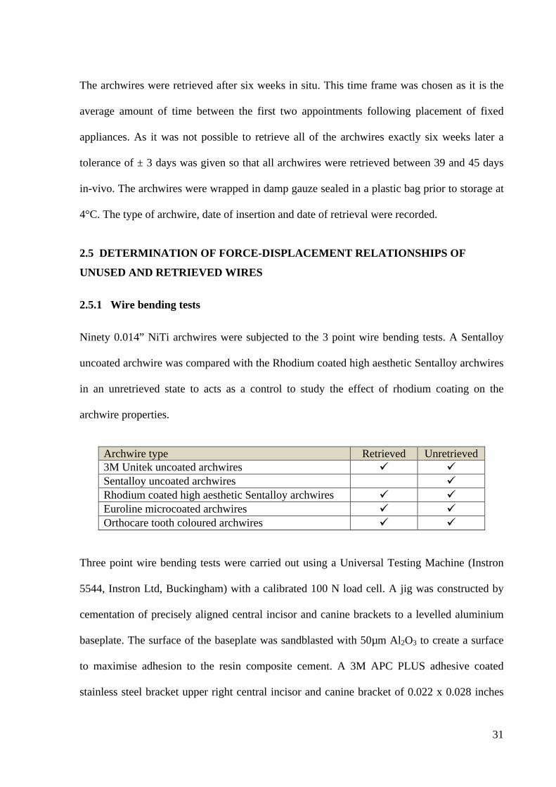
Ninety 0.014” NiTi archwires were subjected to the 3 point wire bending tests. A Sentalloy
uncoated archwire was compared with the Rhodium coated high aesthetic Sentalloy archwires
in an unretrieved state to acts as a control to study the effect of rhodium coating on the
archwire properties.
Archwire type Retrieved Unretrieved 3M Unitek uncoated archwires ü ü Sentalloy uncoated archwires ü Rhodium coated high aesthetic Sentalloy archwires ü ü Euroline microcoated archwires ü ü Orthocare tooth coloured archwires ü ü
Three point wire bending tests were carried out using a Universal Testing Machine (Instron
5544, Instron Ltd, Buckingham) with a calibrated 100 N load cell. A jig was constructed by
cementation of precisely aligned central incisor and canine brackets to a levelled aluminium
baseplate. The surface of the baseplate was sandblasted with 50µm Al2O3 to create a surface
to maximise adhesion to the resin composite cement. A 3M APC PLUS adhesive coated
stainless steel bracket upper right central incisor and canine bracket of 0.022 x 0.028 inches
32
with an MBT prescription was bonded onto the baseplate using 3M Unitek Transbond self
etching primer (3M ESPE, St Paul, MN, USA). The interbracket distance was 14 mm which
is equivalent to the average anatomical distance between the central incisor and canine
brackets. The jig was secured to the base of the UTM.
Each archwire was sectioned at the midpoint into two pieces. The right archwire specimen
was attached to the brackets and ligated using 3M polyurethane elastomeric modules (3M
ESPE, St Paul, MN, USA) in a standard configuration to study displacements up to a
maximum of 1mm whereas the left archwire specimen was similarly ligated and loaded to a
maximum 2 mm displacement. The ligated archwires were centrally loaded using a cylindrical
indenter at a crosshead speed of 1 mm.min-1. A displacement limit of either 1 mm or 2 mm
was set and following loading to this limit unloading at 1 mm.min-1 was immediately
performed. Tests were conducted at 23 ± 1°C. Loading and unloading forces were recorded
with data capture every 15 ms. In total 180 wire specimens from the 9 Groups were tested.
2.5.2 Scanning Electron Microscopy
Representative archwires from each group were examined using Scanning Electron
Microscopy (SEM). The archwires were cut into 10 mm specimens and attached to adhesive
carbon tabs on aluminium studs. The specimens were then gold sputtered using a deposition
current of 20 mA and a deposition time of two minutes using in an Emitech K550x sputter
coater (Quorum Technologies Limited, East Grinstead, UK). Images were captured using a
Zeiss scanning electron microscope was used (Model EVOMA10-159, Series 51-1385-026,
Zeiss GmbH, Jena, Germany) at various magnifications (x100, x1000 and x1500) using an
accelerating voltage of 5 kV and a working distance of 7.5 mm for all magnifications.
33
2.5.3 Surface profilometry
Surface roughness (Ra-value [µm]) of the unused and used archwires was determined using
non-contact profilometry (Talysurf CLI 2000, Taylor-Hobson Precision, Leicester, UK). A
chromatic length aberration gauge (300 µm range in the z-axis; scanning speed of 500 µm/s)
was used to measure line tracts down the long axis of the labial surface of the archwires. A
0.25 mm cut-off Gaussian filter according to ISO 4287 was employed to calculate Ra. One
line track per sample was recorded and the mean Ra-value calculated.
2.6 STATISTICS
Comparions between wire types for parameters obtained from load-deflection curves (peak
load, load at specified values) were made using a one-way ANOVA and post-hoc Tukey tests
(α =0.05). Comparisons for parameters obtained from load-deflection curves (peak load, load
at specified values) between individual wire types in their unused and used states were made
using unpaired t-tests (α =0.05). Mean Ra-data was compared using a two-way ANOVA
where the factors were (wire type and exposure status [used, unused]) (α =0.05). SEM images
were qualitatively assessed at standardised magnifications.
Chapter 3 – Results
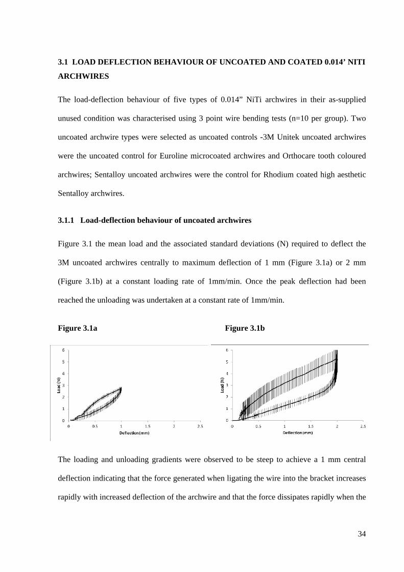
34
3.1 LOAD DEFLECTION BEHAVIOUR OF UNCOATED AND COATED 0.014’ NITI
ARCHWIRES
The load-deflection behaviour of five types of 0.014” NiTi archwires in their as-supplied
unused condition was characterised using 3 point wire bending tests (n=10 per group). Two
uncoated archwire types were selected as uncoated controls -3M Unitek uncoated archwires
were the uncoated control for Euroline microcoated archwires and Orthocare tooth coloured
archwires; Sentalloy uncoated archwires were the control for Rhodium coated high aesthetic
Sentalloy archwires.
3.1.1 Load-deflection behaviour of uncoated archwires
Figure 3.1 the mean load and the associated standard deviations (N) required to deflect the
3M uncoated archwires centrally to maximum deflection of 1 mm (Figure 3.1a) or 2 mm
(Figure 3.1b) at a constant loading rate of 1mm/min. Once the peak deflection had been
reached the unloading was undertaken at a constant rate of 1mm/min.
Figure 3.1a Figure 3.1b The loading and unloading gradients were observed to be steep to achieve a 1 mm central
deflection indicating that the force generated when ligating the wire into the bracket increases
rapidly with increased deflection of the archwire and that the force dissipates rapidly when the
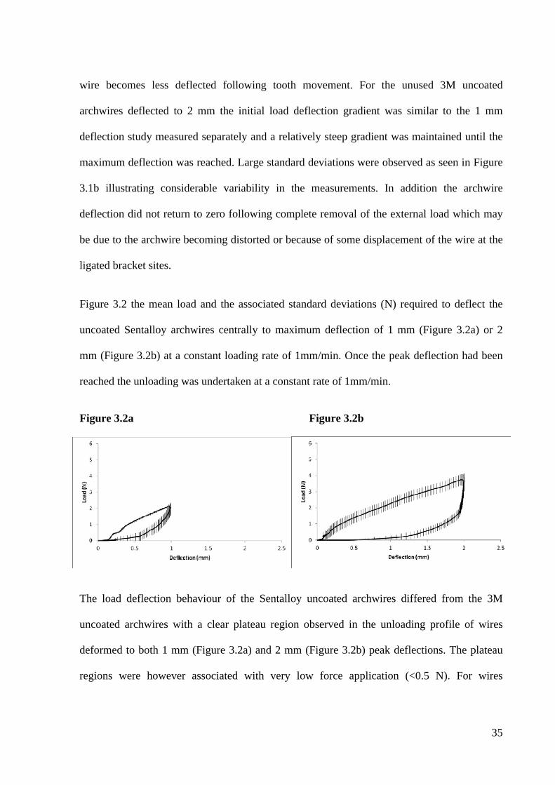
35
wire becomes less deflected following tooth movement. For the unused 3M uncoated
archwires deflected to 2 mm the initial load deflection gradient was similar to the 1 mm
deflection study measured separately and a relatively steep gradient was maintained until the
maximum deflection was reached. Large standard deviations were observed as seen in Figure
3.1b illustrating considerable variability in the measurements. In addition the archwire
deflection did not return to zero following complete removal of the external load which may
be due to the archwire becoming distorted or because of some displacement of the wire at the
ligated bracket sites.
Figure 3.2 the mean load and the associated standard deviations (N) required to deflect the
uncoated Sentalloy archwires centrally to maximum deflection of 1 mm (Figure 3.2a) or 2
mm (Figure 3.2b) at a constant loading rate of 1mm/min. Once the peak deflection had been
reached the unloading was undertaken at a constant rate of 1mm/min.
Figure 3.2a Figure 3.2b
The load deflection behaviour of the Sentalloy uncoated archwires differed from the 3M
uncoated archwires with a clear plateau region observed in the unloading profile of wires
deformed to both 1 mm (Figure 3.2a) and 2 mm (Figure 3.2b) peak deflections. The plateau
regions were however associated with very low force application (<0.5 N). For wires
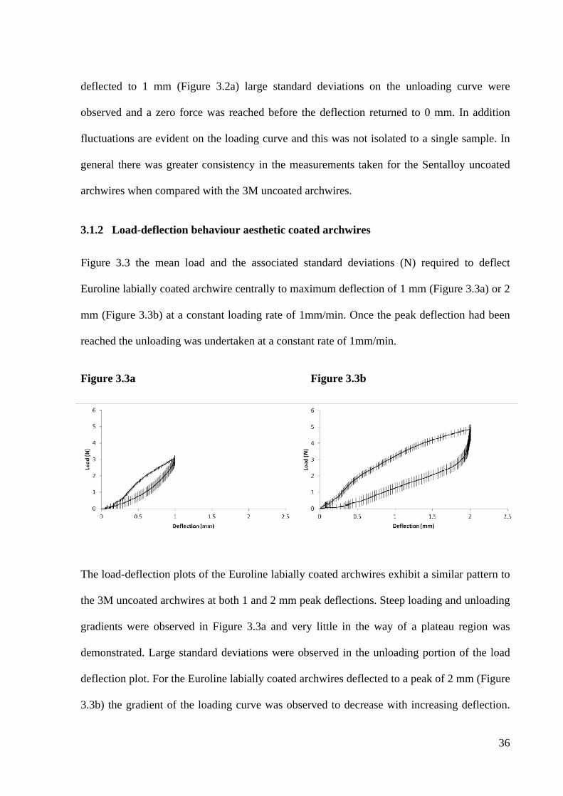
36
deflected to 1 mm (Figure 3.2a) large standard deviations on the unloading curve were
observed and a zero force was reached before the deflection returned to 0 mm. In addition
fluctuations are evident on the loading curve and this was not isolated to a single sample. In
general there was greater consistency in the measurements taken for the Sentalloy uncoated
archwires when compared with the 3M uncoated archwires.
3.1.2 Load-deflection behaviour aesthetic coated archwires
Figure 3.3 the mean load and the associated standard deviations (N) required to deflect
Euroline labially coated archwire centrally to maximum deflection of 1 mm (Figure 3.3a) or 2
mm (Figure 3.3b) at a constant loading rate of 1mm/min. Once the peak deflection had been
reached the unloading was undertaken at a constant rate of 1mm/min.
Figure 3.3a Figure 3.3b
The load-deflection plots of the Euroline labially coated archwires exhibit a similar pattern to
the 3M uncoated archwires at both 1 and 2 mm peak deflections. Steep loading and unloading
gradients were observed in Figure 3.3a and very little in the way of a plateau region was
demonstrated. Large standard deviations were observed in the unloading portion of the load
deflection plot. For the Euroline labially coated archwires deflected to a peak of 2 mm (Figure
3.3b) the gradient of the loading curve was observed to decrease with increasing deflection.
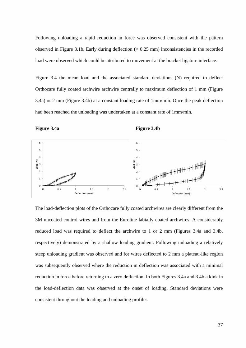
37
Following unloading a rapid reduction in force was observed consistent with the pattern
observed in Figure 3.1b. Early during deflection (< 0.25 mm) inconsistencies in the recorded
load were observed which could be attributed to movement at the bracket ligature interface.
Figure 3.4 the mean load and the associated standard deviations (N) required to deflect
Orthocare fully coated archwire archwire centrally to maximum deflection of 1 mm (Figure
3.4a) or 2 mm (Figure 3.4b) at a constant loading rate of 1mm/min. Once the peak deflection
had been reached the unloading was undertaken at a constant rate of 1mm/min.
Figure 3.4a Figure 3.4b
The load-deflection plots of the Orthocare fully coated archwires are clearly different from the
3M uncoated control wires and from the Euroline labially coated archwires. A considerably
reduced load was required to deflect the archwire to 1 or 2 mm (Figures 3.4a and 3.4b,
respectively) demonstrated by a shallow loading gradient. Following unloading a relatively
steep unloading gradient was observed and for wires deflected to 2 mm a plateau-like region
was subsequently observed where the reduction in deflection was associated with a minimal
reduction in force before returning to a zero deflection. In both Figures 3.4a and 3.4b a kink in
the load-deflection data was observed at the onset of loading. Standard deviations were
consistent throughout the loading and unloading profiles.
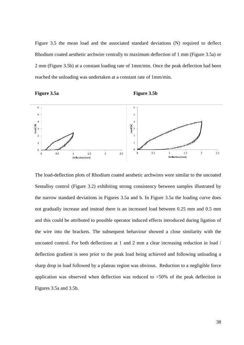
38
Figure 3.5 the mean load and the associated standard deviations (N) required to deflect
Rhodium coated aesthetic archwire centrally to maximum deflection of 1 mm (Figure 3.5a) or
2 mm (Figure 3.5b) at a constant loading rate of 1mm/min. Once the peak deflection had been
reached the unloading was undertaken at a constant rate of 1mm/min.
Figure 3.5a Figure 3.5b
The load-deflection plots of Rhodium coated aesthetic archwires were similar to the uncoated
Sentalloy control (Figure 3.2) exhibiting strong consistency between samples illustrated by
the narrow standard deviations in Figures 3.5a and b. In Figure 3.5a the loading curve does
not gradually increase and instead there is an increased load between 0.25 mm and 0.5 mm
and this could be attributed to possible operator induced effects introduced during ligation of
the wire into the brackets. The subsequent behaviour showed a close similarity with the
uncoated control. For both deflections at 1 and 2 mm a clear increasing reduction in load /
deflection gradient is seen prior to the peak load being achieved and following unloading a
sharp drop in load followed by a plateau region was obvious. Reduction to a negligible force
application was observed when deflection was reduced to <50% of the peak deflection in
Figures 3.5a and 3.5b.
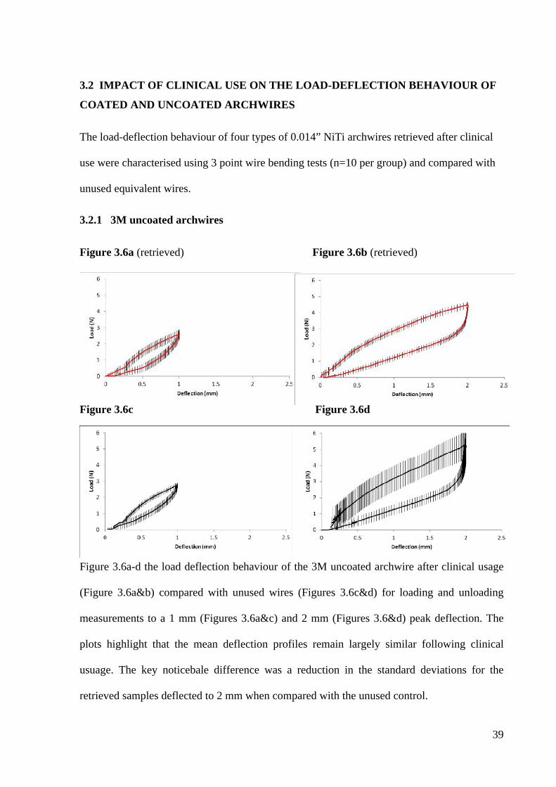
39
3.2 IMPACT OF CLINICAL USE ON THE LOAD-DEFLECTION BEHAVIOUR OF
COATED AND UNCOATED ARCHWIRES
The load-deflection behaviour of four types of 0.014” NiTi archwires retrieved after clinical
use were characterised using 3 point wire bending tests (n=10 per group) and compared with
unused equivalent wires.
3.2.1 3M uncoated archwires
Figure 3.6a (retrieved) Figure 3.6b (retrieved)
Figure 3.6c Figure 3.6d
Figure 3.6a-d demonstrates the load deflection behaviour of the uncoated 3M 0.014” NiTi
Figure 3.6a-d the load deflection behaviour of the 3M uncoated archwire after clinical usage
(Figure 3.6a&b) compared with unused wires (Figures 3.6c&d) for loading and unloading
measurements to a 1 mm (Figures 3.6a&c) and 2 mm (Figures 3.6&d) peak deflection. The
plots highlight that the mean deflection profiles remain largely similar following clinical
usuage. The key noticebale difference was a reduction in the standard deviations for the
retrieved samples deflected to 2 mm when compared with the unused control.
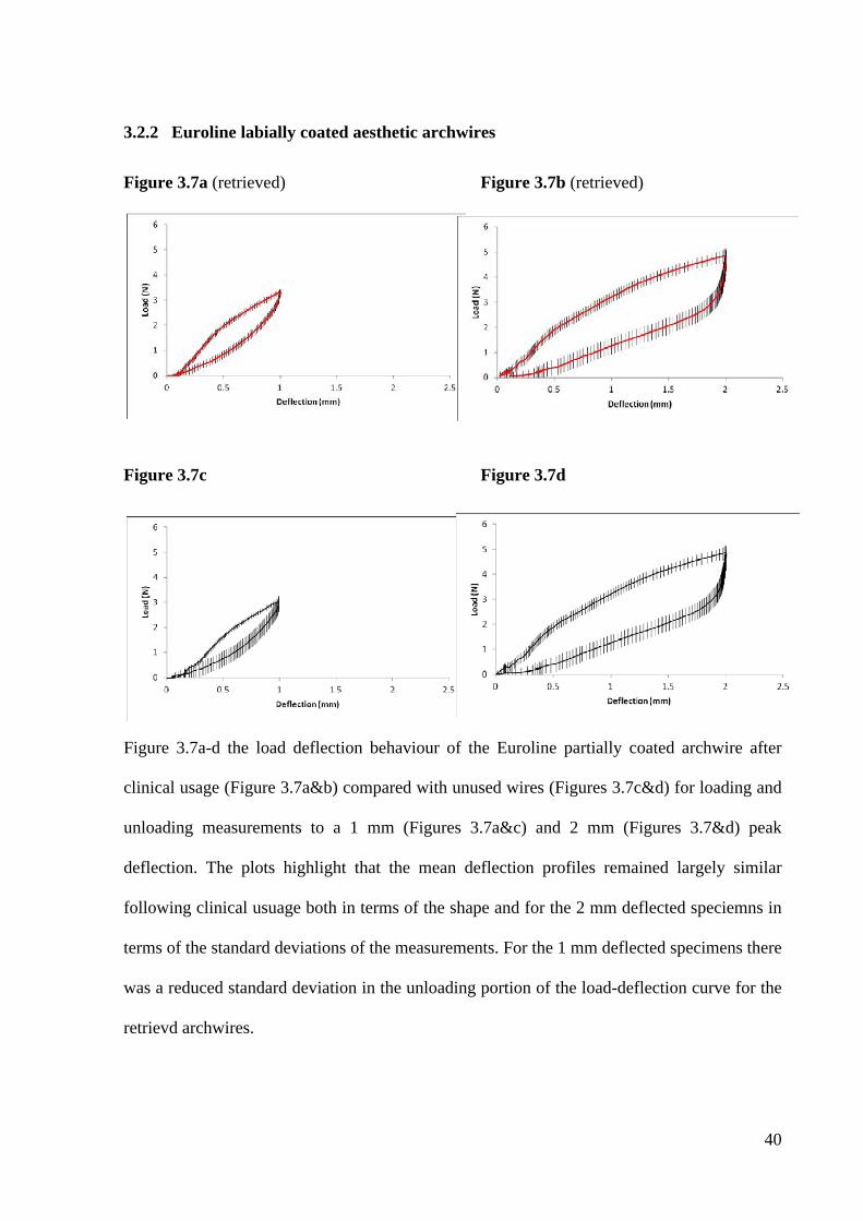
40
3.2.2 Euroline labially coated aesthetic archwires
Figure 3.7a (retrieved) Figure 3.7b (retrieved)
Figure 3.7c Figure 3.7d
Figure 3.7a-d the load deflection behaviour of the Euroline partially coated archwire after
clinical usage (Figure 3.7a&b) compared with unused wires (Figures 3.7c&d) for loading and
unloading measurements to a 1 mm (Figures 3.7a&c) and 2 mm (Figures 3.7&d) peak
deflection. The plots highlight that the mean deflection profiles remained largely similar
following clinical usuage both in terms of the shape and for the 2 mm deflected speciemns in
terms of the standard deviations of the measurements. For the 1 mm deflected specimens there
was a reduced standard deviation in the unloading portion of the load-deflection curve for the
retrievd archwires.
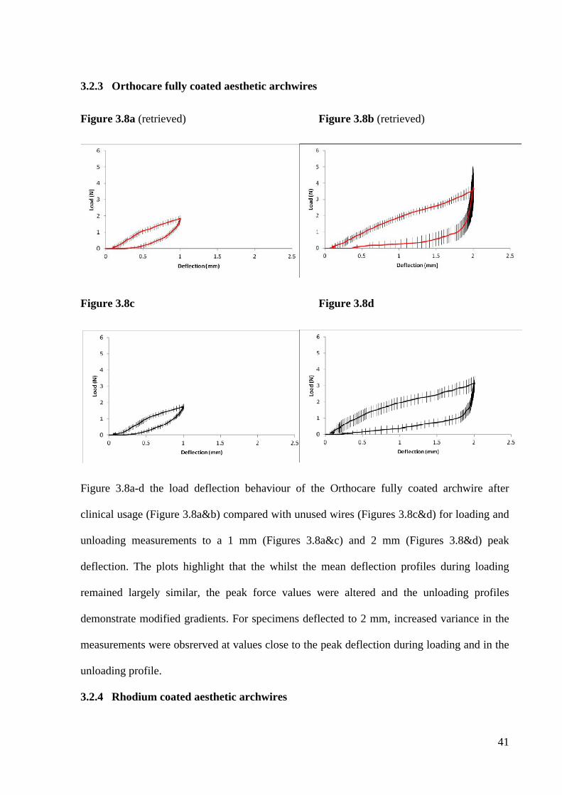
41
3.2.3 Orthocare fully coated aesthetic archwires
Figure 3.8a (retrieved) Figure 3.8b (retrieved)
Figure 3.8c Figure 3.8d
Figure 3.8a-d the load deflection behaviour of the Orthocare fully coated archwire after
clinical usage (Figure 3.8a&b) compared with unused wires (Figures 3.8c&d) for loading and
unloading measurements to a 1 mm (Figures 3.8a&c) and 2 mm (Figures 3.8&d) peak
deflection. The plots highlight that the whilst the mean deflection profiles during loading
remained largely similar, the peak force values were altered and the unloading profiles
demonstrate modified gradients. For specimens deflected to 2 mm, increased variance in the
measurements were obsrerved at values close to the peak deflection during loading and in the
unloading profile.
3.2.4 Rhodium coated aesthetic archwires
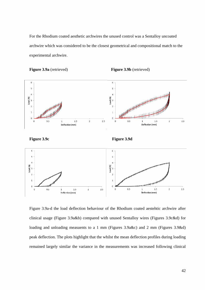
42
For the Rhodium coated aesthetic archwires the unused control was a Sentalloy uncoated
archwire which was considered to be the closest geometrical and compositional match to the
experimental archwire.
Figure 3.9a (retrieved) Figure 3.9b (retrieved)
Figure 3.9c Figure 3.9d
Figure 3.9a-d the load deflection behaviour of the Rhodium coated aestehtic archwire after
clinical usage (Figure 3.9a&b) compared with unused Sentalloy wires (Figures 3.9c&d) for
loading and unloading measuents to a 1 mm (Figures 3.9a&c) and 2 mm (Figures 3.9&d)
peak deflection. The plots highlight that the whilst the mean deflection profiles during loading
remained largely similar the variance in the measurements was increased following clinical
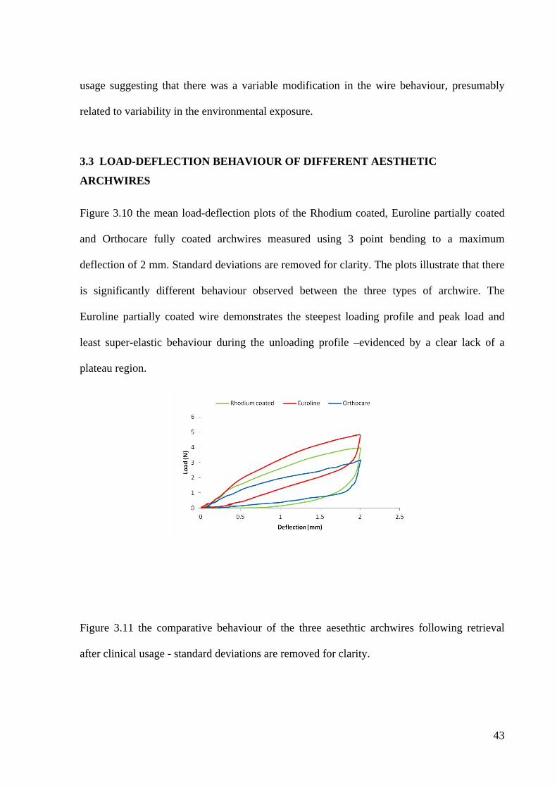
43
usage suggesting that there was a variable modification in the wire behaviour, presumably
related to variability in the environmental exposure.
3.3 LOAD-DEFLECTION BEHAVIOUR OF DIFFERENT AESTHETIC
ARCHWIRES
Figure 3.10 the mean load-deflection plots of the Rhodium coated, Euroline partially coated
and Orthocare fully coated archwires measured using 3 point bending to a maximum
deflection of 2 mm. Standard deviations are removed for clarity. The plots illustrate that there
is significantly different behaviour observed between the three types of archwire. The
Euroline partially coated wire demonstrates the steepest loading profile and peak load and
least super-elastic behaviour during the unloading profile –evidenced by a clear lack of a
plateau region.
Figure 3.11 the comparative behaviour of the three aesethtic archwires following retrieval
after clinical usage - standard deviations are removed for clarity.
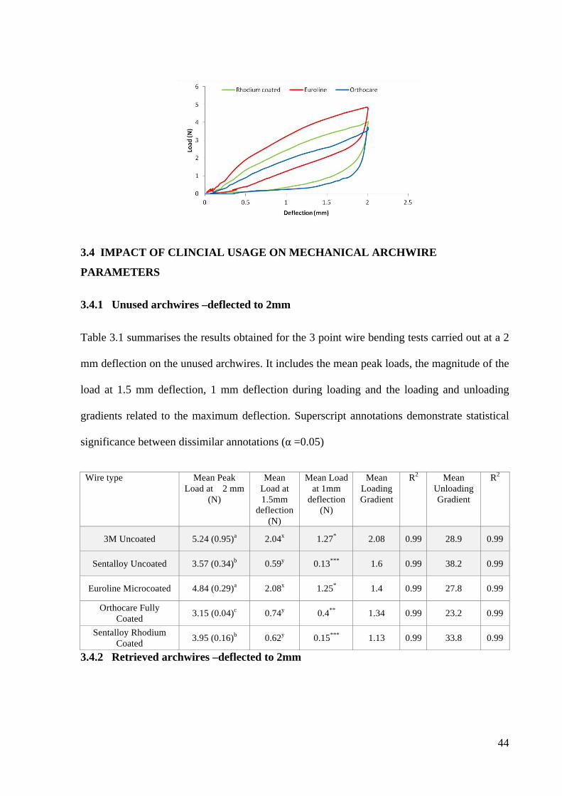
44
3.4 IMPACT OF CLINCIAL USAGE ON MECHANICAL ARCHWIRE
PARAMETERS
3.4.1 Unused archwires –deflected to 2mm
Table 3.1 summarises the results obtained for the 3 point wire bending tests carried out at a 2
mm deflection on the unused archwires. It includes the mean peak loads, the magnitude of the
load at 1.5 mm deflection, 1 mm deflection during loading and the loading and unloading
gradients related to the maximum deflection. Superscript annotations demonstrate statistical
significance between dissimilar annotations (α =0.05)
3.4.2 Retrieved archwires –deflected to 2mm
Wire type Mean Peak Load at 2 mm
(N)
Mean Load at 1.5mm
deflection (N)
Mean Load at 1mm
deflection (N)
Mean Loading Gradient
R2 Mean Unloading Gradient
R2
3M Uncoated 5.24 (0.95)a 2.04x 1.27* 2.08 0.99 28.9 0.99
Sentalloy Uncoated 3.57 (0.34)b 0.59y 0.13*** 1.6 0.99 38.2 0.99
Euroline Microcoated 4.84 (0.29)a 2.08x 1.25* 1.4 0.99 27.8 0.99
Orthocare Fully Coated 3.15 (0.04)c 0.74y 0.4** 1.34 0.99 23.2 0.99
Sentalloy Rhodium Coated 3.95 (0.16)b 0.62y 0.15*** 1.13 0.99 33.8 0.99
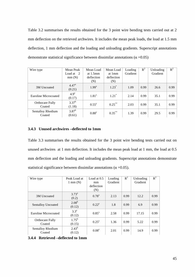
45
Table 3.2 summarises the results obtained for the 3 point wire bending tests carried out at 2
mm deflection on the retrieved archwires. It includes the mean peak loads, the load at 1.5 mm
deflection, 1 mm deflection and the loading and unloading gradients. Superscript annotations
demonstrate statistical significance between dissimilar annotations (α =0.05)
3.4.3 Unused archwires –deflected to 1mm
Table 3.3 summarises the results obtained for the 3 point wire bending tests carried out on
unused archwires at 1 mm deflection. It includes the mean peak load at 1 mm, the load at 0.5
mm deflection and the loading and unloading gradients. Superscript annotations demonstrate
statistical significance between dissimilar annotations (α =0.05).
3.4.4 Retrieved –deflected to 1mm
Wire type Mean Peak Load at 2
mm (N)
Mean Load at 1.5mm deflection
(N)
Mean Load at 1mm
deflection (N)
Loading Gradient
R2 Unloading Gradient
R2
3M Uncoated 4.47a
(0.21) 1.99x 1.23* 1.09 0.99 26.6 0.99
Euroline Microcoated 4.9a
(0.17) 1.81x 1.21* 2.14 0.99 35.1 0.99
Orthocare Fully Coated
3.37b
(1.18) 0.55y 0.25** 2.03 0.99 35.1 0.99
Sentalloy Rhodium Coated
3.87b
(0.61) 0.88y 0.35** 1.39 0.99 29.5 0.99
Wire type Peak Load at 1 mm (N)
Load at 0.5 mm
deflection (N)
Loading Gradient
R2 Unloading Gradient
R2
3M Uncoated 3.73a
(0.2) 0.78x 2.13 0.99 12.2 0.99
Sentalloy Uncoated 2.08b
(0.12) 0.22y 1.8 0.99 6.9 0.99
Euroline Microcoated 3.3a
(0.12) 0.85x 2.58 0.99 17.15 0.99
Orthocare Fully Coated
1.75b
(0.15) 0.25y 1.36 0.99 5.22 0.99
Sentalloy Rhodium Coated
2.43b
(0.12) 0.08z 2.01 0.99 14.9 0.99
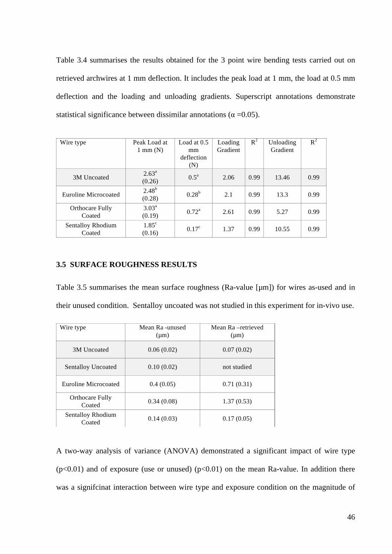
46
Table 3.4 summarises the results obtained for the 3 point wire bending tests carried out on
retrieved archwires at 1 mm deflection. It includes the peak load at 1 mm, the load at 0.5 mm
deflection and the loading and unloading gradients. Superscript annotations demonstrate
statistical significance between dissimilar annotations (α =0.05).
3.5 SURFACE ROUGHNESS RESULTS
Table 3.5 summarises the mean surface roughness (Ra-value [µm]) for wires as-used and in
their unused condition. Sentalloy uncoated was not studied in this experiment for in-vivo use.
A two-way analysis of variance (ANOVA) demonstrated a significant impact of wire type
(p<0.01) and of exposure (use or unused) (p<0.01) on the mean Ra-value. In addition there
was a signifcinat interaction between wire type and exposure condition on the magnitude of
Wire type Peak Load at 1 mm (N)
Load at 0.5 mm
deflection (N)
Loading Gradient
R2 Unloading Gradient
R2
3M Uncoated 2.63a
(0.26) 0.5a 2.06 0.99 13.46 0.99
Euroline Microcoated 2.48b
(0.28) 0.28b 2.1 0.99 13.3 0.99
Orthocare Fully Coated
3.03a
(0.19) 0.72a 2.61 0.99 5.27 0.99
Sentalloy Rhodium Coated
1.85c
(0.16) 0.17c 1.37 0.99 10.55 0.99
Wire type Mean Ra -unused (µm)
Mean Ra –retrieved (µm)
3M Uncoated 0.06 (0.02) 0.07 (0.02)
Sentalloy Uncoated 0.10 (0.02) not studied
Euroline Microcoated 0.4 (0.05) 0.71 (0.31)
Orthocare Fully Coated 0.34 (0.08) 1.37 (0.53)
Sentalloy Rhodium Coated 0.14 (0.03) 0.17 (0.05)
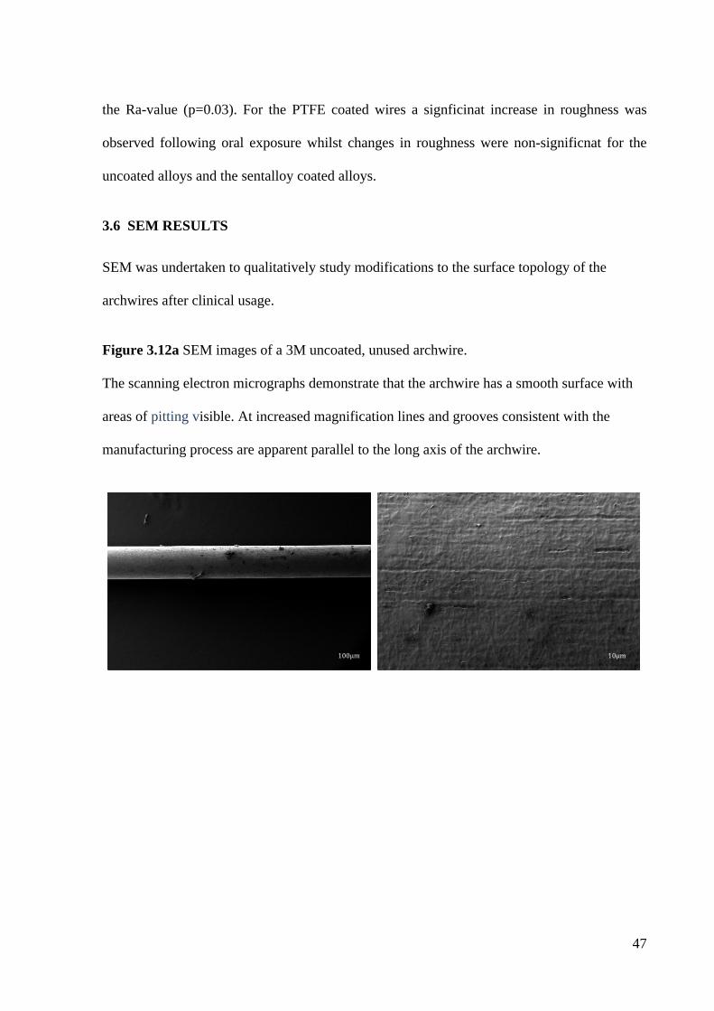
47
the Ra-value (p=0.03). For the PTFE coated wires a signficinat increase in roughness was
observed following oral exposure whilst changes in roughness were non-significnat for the
uncoated alloys and the sentalloy coated alloys.
3.6 SEM RESULTS
SEM was undertaken to qualitatively study modifications to the surface topology of the
archwires after clinical usage.
Figure 3.12a SEM images of a 3M uncoated, unused archwire.
The scanning electron micrographs demonstrate that the archwire has a smooth surface with
areas of pitting visible. At increased magnification lines and grooves consistent with the
manufacturing process are apparent parallel to the long axis of the archwire.
100μm
10μm
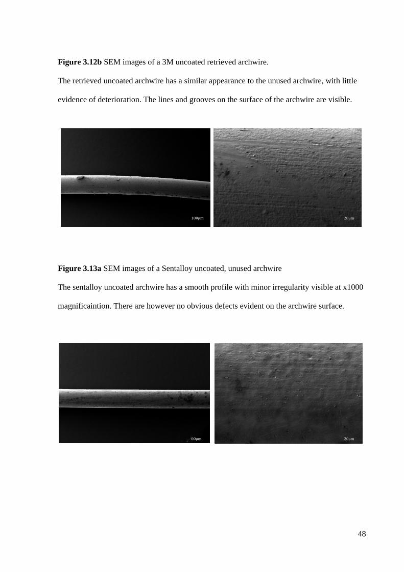
48
Figure 3.12b SEM images of a 3M uncoated retrieved archwire.
The retrieved uncoated archwire has a similar appearance to the unused archwire, with little
evidence of deterioration. The lines and grooves on the surface of the archwire are visible.
Figure 3.13a SEM images of a Sentalloy uncoated, unused archwire
The sentalloy uncoated archwire has a smooth profile with minor irregularity visible at x1000
magnificaintion. There are however no obvious defects evident on the archwire surface.
100μm
20μm
00μm
20μm
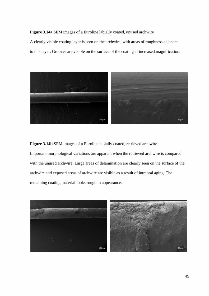
49
Figure 3.14a SEM images of a Euroline labially coated, unused archwire
A clearly visible coating layer is seen on the archwire, with areas of roughness adjacent
to this layer. Grooves are visible on the surface of the coating at increased magnification.
Figure 3.14b SEM images of a Euroline labially coated, retrieved archwire
Important morphological variations are apparent when the retrieved archwire is compared
with the unused archwire. Large areas of delamination are clearly seen on the surface of the
archwire and exposed areas of archwire are visible as a result of intraoral aging. The
remaining coating material looks rough in appearance.
200μm
10μm
10μm
10μm
200μm
1
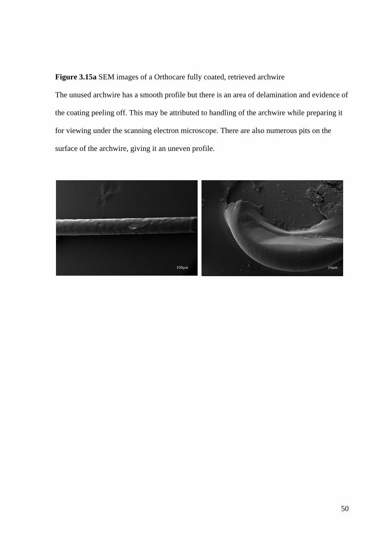
50
Figure 3.15a SEM images of a Orthocare fully coated, retrieved archwire
The unused archwire has a smooth profile but there is an area of delamination and evidence of
the coating peeling off. This may be attributed to handling of the archwire while preparing it
for viewing under the scanning electron microscope. There are also numerous pits on the
surface of the archwire, giving it an uneven profile.
100μm
10μm
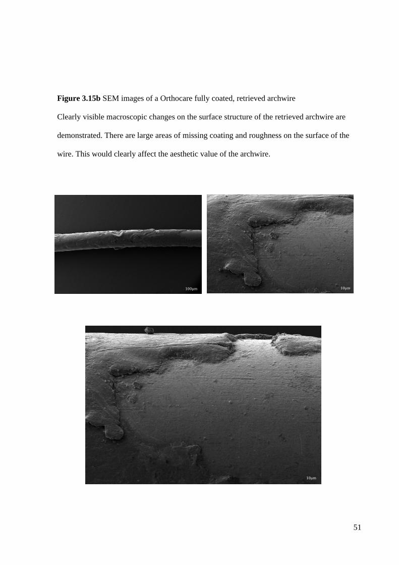
51
Figure 3.15b SEM images of a Orthocare fully coated, retrieved archwire
Clearly visible macroscopic changes on the surface structure of the retrieved archwire are
demonstrated. There are large areas of missing coating and roughness on the surface of the
wire. This would clearly affect the aesthetic value of the archwire.
100μm
10μm
10μm
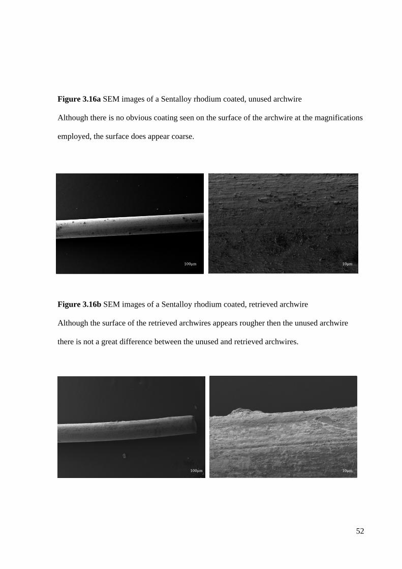
52
Figure 3.16a SEM images of a Sentalloy rhodium coated, unused archwire
Although there is no obvious coating seen on the surface of the archwire at the magnifications
employed, the surface does appear coarse.
Figure 3.16b SEM images of a Sentalloy rhodium coated, retrieved archwire
Although the surface of the retrieved archwires appears rougher then the unused archwire
there is not a great difference between the unused and retrieved archwires.
10μm
100μm
10μm
100μm
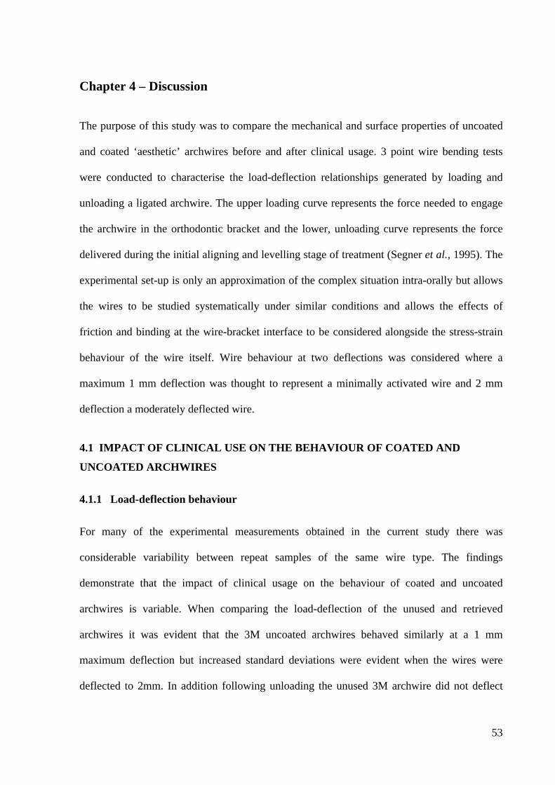
53
Chapter 4 – Discussion The purpose of this study was to compare the mechanical and surface properties of uncoated
and coated ‘aesthetic’ archwires before and after clinical usage. 3 point wire bending tests
were conducted to characterise the load-deflection relationships generated by loading and
unloading a ligated archwire. The upper loading curve represents the force needed to engage
the archwire in the orthodontic bracket and the lower, unloading curve represents the force
delivered during the initial aligning and levelling stage of treatment (Segner et al., 1995). The
experimental set-up is only an approximation of the complex situation intra-orally but allows
the wires to be studied systematically under similar conditions and allows the effects of
friction and binding at the wire-bracket interface to be considered alongside the stress-strain
behaviour of the wire itself. Wire behaviour at two deflections was considered where a
maximum 1 mm deflection was thought to represent a minimally activated wire and 2 mm
deflection a moderately deflected wire.
4.1 IMPACT OF CLINICAL USE ON THE BEHAVIOUR OF COATED AND
UNCOATED ARCHWIRES
4.1.1 Load-deflection behaviour
For many of the experimental measurements obtained in the current study there was
considerable variability between repeat samples of the same wire type. The findings
demonstrate that the impact of clinical usage on the behaviour of coated and uncoated
archwires is variable. When comparing the load-deflection of the unused and retrieved
archwires it was evident that the 3M uncoated archwires behaved similarly at a 1 mm
maximum deflection but increased standard deviations were evident when the wires were
deflected to 2mm. In addition following unloading the unused 3M archwire did not deflect
54
back to a zero reading. These observations can be explained by either permanent distortion of
the archwire (deformation beyond the yield point) occurring or that there has been some
sliding of the archwire at the ligation sites. Given a maximum deflection of 2 mm was
introduced the latter mechanism was considered more likely and therefore is considered in the
context of the behaviour of all of the experimental measurements. The behaviour of Orthocare
fully coated archwires were largely similar and interestingly the loading curves exhibited
small fluctuations in the measured load as the wire was been deflected. This observation was
attributed to inconsistencies in the friction between the wire and the ligation/bracket site and
was only observed in the coated archwire samples. The only notable difference between
unused and retrieved Orthocare fully coated archwires when deflected to 2 mm were the
steeper unloading curves with the retrieved archwires and greater standard deviations
suggesting the retrieved fully coated wires lose force rapidly once the tooth starts to move and
that the force delivered by the wires is more variable.
Load deflection curves for the rhodium coated archwires demonstrated that when the wires
were deflected to 1mm both the unused and retrieved archwires exhibited steep loading and
unloading profiles which is indicative of little sensitivity in force application and rapid loss of
useable force following small amounts of tooth movement. Similarly to the Orthocare fully
coated archwires there was some unevenness in the initial loading curve which was attributed
to wire movement at the ligation site. When deflected to both 1 mm and 2 mm the retrieved
rhodium coated archwires have greater standard deviations than the unused wires, again
suggesting that the behaviour of retrieved archwires is less predictable after 6 weeks of
clinical use. This in turn can be related to either modification of the surface (surface
deterioration or development of surface biofilm) or to alloy modification itself. The latter
55
although less likely cannot be discarded as the control comparisons for the Rhodium coated
archwires were an unused Sentalloy equivalent.
The load-deflection behaviour of the Euroline labially coated archwires was similar for
unused and retrieved samples. Interestingly when the wires were deflected to 1 mm steep
loading and unloading curves were evident with no obvious plateaus and signs of stress
induced phase transformations. The behaviour could be typical of the wire itself or could
represent a modification of the stress-strain behaviour of the wire by the coating itself. The
Euroline archwires were labially coated and the force applied during 3 point bending was on
the contralateral surface putting the coating into tension during the 3 point bending test. When
a greater deflection of 2mm was induced the wire behaved in a more typical manner of NiTi
archwires. As seen with previous archwires there are greater standard deviations in the overall
behaviour of the retrieved archwires which is again indicative of some modification to the
coating and/or wire which is sensitive to the specific environmental exposure.
4.1.2 Engagement and active forces
No differences in the force needed to engage the Orthocare fully coated NiTi archwires before
and after 6 weeks of clinical use were observed despite obvious degradation and delamination
of the coating. The Euroline labially coated archwires did however have a reduced peak load
at 1mm deflection after 6 weeks of usage, suggesting that reduced force is needed to engage
the archwire after clinical use. This suggests that an intact labial coating may contribute some
stiffness to the wire which is subsequently lost after a period of clinical usage. From a clinical
perspective the predictability of this behaviour change in the context of when it happens is
uncertain. Alternatively the reduced load to achieve a 1mm deflection may also be related to
sliding at the ligated brackets but as the load deflection plots tended to return to the unloaded
56
origin following the loading cycle this was considered to be less likely. The 3M uncoated
archwires also produced statistically significant reduced loading forces at 2 mm deflection
following clinical usage.
Retrieved Orthocare fully coated archwires produced lower unloading forces at 1.5 mm, 1 mm
and 0.5 mm deflection compared with as-received fully coated archwires. Similarly, retrieved
Euroline labially coated archwires generated lower unloading forces at 1.5 mm and 0.5 mm
deflection. The most likely reason for this is that increased friction is created between the
irregular surface of the coated archwire and the bracket. Defects on the surface of the
archwires where the edges of the brackets and the archwires contact may impede the wire
sliding through the brackets during the 3 point wire bending tests. A previous study by
Elayyan et al (2008) deflected unused and retrieved coated archwires by 2 mm and 4 mm and
they also found that retrieved coated archwires deflected to 2 mm produced lower unloading
forces whereas when the wires were deflected by 4 mm they generated unloading force values
of zero. After examining the archwires they concluded that they were 'jammed' in place and
prevented from sliding through the brackets due to damage of the coating and increased
friction. This 'jamming' effect resulted in the wires remaining static as the load was released.
Bradley et al (2013) in contrast found that retrieved aesthetic archwires had significantly
higher stiffness and force values than the same wires before use and concluded that as the
coating was lost during clinical use the archwires behaved more like their uncoated
counterparts.
The unloading gradients of the retrieved Orthocare fully coated archwires deflected to 1mm
was significantly increased suggesting that the force delivered to the teeth reduces rapidly
following initial movement and alignment of the teeth. When comparing the peak load of the
57
archwires deflected to 1 mm and 2 mm before and after use differences were observed. The
difference in peak load of the Euroline archwires deflected to 2 mm before and after use was
not statistically significant whereas the Euroline archwires produced reduced forces after 6
weeks of clinical use when deflected to just 1 mm. When the archwires are deflected to 1 mm
some of the movement of the wire will be the stretching of the elastomeric modules and static
friction may not be overcome. When the archwires are deflected to 2 mm however, they are
more likely to displace and overcome static friction irrespective of coating state and hence
you have less of a difference in the peak loads before and after use.
4.2 IMPACT OF COATING ON THE BEHAVIOUR OF NICKEL-TITANIUM
ARCHWIRES
3 point wire bending tests were also used to determine the tooth-moving properties of the
coated and uncoated archwires. The loading and unloading curves of the Sentalloy rhodium
coated archwires are steeper than the uncoated archwires. Both wires have steep unloading
curves which suggest that once the tooth starts moving the force delivered is rapidly reduced.
The rhodium coated archwire deflected to 2 mm performed better than the uncoated Sentalloy
archwire, producing a higher unloading response. The wires also produced higher loading
forces when deflected to 1 mm. This observation may be attributed to minor deviations in the
individual dimensions of the archwires and consequential variations in the load deflection
properties of the uncoated and rhodium coated archwires. It may also be that the
manufacturers use different stock archwires for rhodium coated wires as opposed to simply
coating the original archwires. There were greater standard deviations observed for the
uncoated Sentalloy archwires suggesting these wires behaviour are more unpredictable.
58
The load deflection curves of the 3M uncoated, Euroline labially coated and Orthocare fully
coated archwires when deflected to 1 mm are similar suggesting that at small deflections the
coated archwires behaviour initially in a similar way to the uncoated counterparts. However
when deflected to 2 mm differences in the wire behaviour became apparent. It is likely at
1mm deflection that magnitude of wire movement at the ligated bracket site will be small
however at 2mm deflections there is evidence from inconsistencies in the loading profiles that
some translational movement of the wire through the bracket must occur. Associated with this
was considerable variability between repeat samples leading to large measurement standard
deviations. The 3M uncoated archwire deflected to 2 mm demonstrated particular variability
which may be explained by operator variability in securing the wire to the experimental jig or
by intrinsic variability in the surface finish of the wire provided ‘as manufactured’.
There was no statistically significant difference noted between the loading and unloading
forces of the 3M uncoated, Orthocare fully coated and Euroline labially coated archwires
when deflected to 2 mm and 1 mm. Previous studies that have found lower unloading forces
for the coated archwires suggested this was most likely due to the coated wires having smaller
cross-sectional dimensions. A recent study by Da Silva et al (2013) examined the inner alloy
core dimensions of a variety of coated archwires and found no significant difference in the
cross-sectional diameter of the coated and uncoated archwires for one manufacturer (TP
Orthodontics: Aesthetic Shiny Bright and non-coated Shiny Bright archwires). Subsequently,
Washington et al (2014) used a Nikon Profile Projector to examine the dimensions of
archwires at 100x magnification and found similar results for TP and GH wires. Their study
also found the archwires produced by manufacturers with approximately the same dimensions
as their uncoated counterparts exhibited similar load responses as the uncoated archwires. As
the thickness of the coated wires used in this study was only between 0.002” - 0.005” the
59
archwire dimensions of the coated and uncoated wires may be similar, resulting in coated
wires that perform as well as their uncoated counterparts. The deflection of the archwires by 1
mm or 2 mm did not impact on the behaviour of the wires when subjected to 3 point wire
bending tests.
Ellayan et al (2008) used self-ligating brackets when testing the mechanical properties of the
coated and uncoated archwires before and after clinical use and found similar loading and
unloading forces. This may be due to the reduced friction associated with self-ligating
brackets. They may not be as affected by the delamination and increased surface roughness as
conventional brackets. In addition, Eliades et al (2000) examined the surface characteristics of
coated archwires after 1-6 months of clinical use and found that the method of ligation i.e.
stainless steel ligatures versus elastomeric modules, did not influence the characteristics of
biofilm maturation or the aging pattern.
Comparisons of the force levels generated by coated archwires in previous studies cannot be
made as there are no other studies that have used 0.014” coated archwires in 3 point wire
bending tests, with round 0.016” and 0.018”x 0.025” rectangular archwires being more
commonly used for testing. In addition there are other variables such as method of ligation,
length of archwire span, the size of the loading instrument, loading speed and the direction of
testing that can alter the results between studies.
4.3 SURFACE CHARACTERISTICS OF UNUSED AND RETRIEVED COATED
AND COATED ARCHWIRES
SEM was carried out on unused and retrieved archwires under 100, 1000 and 1,500
magnification to analyse the surfaces of the wires. The uncoated 3M and Sentalloy archwires
showed the typical surface characteristics of superelastic archwires and had smooth surfaces
60
with some evidence of the manufacturing process visible and no obvious defects. The PTFE
coated Orthocare and Euroline unused archwires showed grooves and pitting and the rhodium
coated archwires had a smooth profile with minor irregularities visible at x1000
magnification. After 6 weeks of clinical use the PTFE coated archwires demonstrated a
considerable amount of deterioration, this is consistent with the results of previous studies
(Neumann et al, 2002; Elayyan et al 2008; Bradley et al, 2013). The loss of coating after a
mean period of 21-55 days has been reported to be between 25% to 72.9% ( Elayyan et al
2008; Bradley et al, 2013; Da Silva et al, 2013). Although there was a loss of coating the NiTi
wires beneath the coating appeared smooth and defect-free. The deterioration in the surface
PTFE coating was associated with a concomitant significant increase in the measured surface
rough (mean Ra values) which would clinically impact on friction within the bracket slots.
The delamination and deterioration of the coating of the archwires may affect the aesthetic
properties of the wires and consequently patient satisfaction. There are also a number of
clinical consequences that may arise as a result of the loss of the coating. Plaque may
accumulate more readily around areas of delamination, making oral hygiene more challenging
in these areas. Although the wire beneath where the coating appeared without defects, it may
in time become more susceptible to corrosion. The sliding properties of the archwires are also
likely to reduce significantly as the bracket edges become entrapped inside the defects
although further clarification of the implication of surface roughness on friction is needed.
Excessive wear was noted where the wires were engaged with the brackets. This may be as a
result of the force used to ligate the wires with elastomeric modules or it may be attributed to
the ploughing effect of the coating during sliding of the wires on the brackets.
61
Given the delamination and deterioration of the coating following clinical use it is probable
that these wires may not satisfy the aesthetic demands of the patients that request aesthetic
appliances. Bradley et al (2013) found that at least half of patients were aware of texture and
colour changes to PTFE coated archwires over time. There have been no other studies that
have looked at patient satisfaction with aesthetic archwires. Improvements to the coating
technique or the development of clinically acceptable composite archwires in the future may
overcome the limitations of aesthetic archwires.
4.4 LIMITATIONS OF THE STUDY
The results of this study are limited to the materials tested. Therefore they can only be applied
to the specific 0.014” round NiTi archwires used with pre-adjusted edgewise brackets and
conventional elastomeric ligation. Rectangular and stainless steel archwires may behave
differently. In addition the archwires were deflected to 1 mm and 2 mm and the archwires
may behave differently if they are deflected to greater than 2 mm or indeed less than 1 mm.
As previously discussed the method of ligation may also influence the behaviour of the
superelastic coated and uncoated archwires.
Retrieval analysis has gained interest in recent years as it provides information on the
performance of dental materials in the environment in which they are intended to operate and
it also aids in assessing any alterations of the properties of the materials that occur during
their clinical use. The sequence in the changes to the properties of the archwires cannot be
provided by retrieval analysis and this is a drawback of this form of mechanical testing. The
limitations of using raw data from the mechanical testing of archwires should also be
acknowledged. Although 3 point wire bending tests are the most commonly used tests for
62
assessing the performance of archwires the situation in the mouth may be different and
statistically significant values may not translate into altered clinical performance.
There are many factors which could have influenced the integrity of the coated archwires and
thus the results, such as differences in oral hygiene habits, the use of fluoride mouthwash and
toothpaste, oral pH, biological factors and the intraoral exposure period. Although the SEM
revealed significant areas of delamination of the coating on the archwires it may have been
useful to quantify the amount of remaining coating. This has been carried out in three
previous studies using different methods. Elayyan et al (2008) transferred digital images of
the archwires into a computer and used an Image®J program and excel to calculate the
remaining coating. Bradley et al (2013) scanned images of the wires, imported them though
Matlab and used csvwrite to apply three numerical values for each pixel. The percentage of
the wire was divided by the sum of the percentage of the coating and the wire to calculate an
evaluation percentage. Da Silva et al (2013) used Image ProPlus 4.5 software to calculate the
amount of coating remaining on the retrieved archwires. However, when relating coating loss
to load deflection data it is essential to recognise that quantification of coating deterioration
may not always be relevant as it is likely to be localised patterns of deterioration at zones of
direct interaction with the bracket or ligature which are responsible for the variability in
behaviour observed. A further weakness of this study is that the 3 point wire bending tests
were carried out at 24 °C instead of 36 °C. This reduced temperature may lead to reduced load
response values as the superelastic deformation behaviour of nickel titanium archwires is
highly dependent on deformation temperature. The stresses for superelastic loading and
unloading increase with increasing temperature.
63
Chapter 5 – Conclusion The purpose of this study was to examine the mechanical and surface properties of coated
‘aesthetic’ archwires before and after clinical use.
1. The findings demonstrate that the impact of clinical usage on the behaviour of coated
archwires is variable. The archwires behaviour after 6 weeks of clinical use is more
unpredictable than that of unused archwires with greater variability between the repeat
samples. This can be related to either modification of the surface (surface deterioration
or development of surface biofilm) or to alloy modification itself. In addition the
retrieved PTFE coated archwires produced lower unloading forces than unused
archwires which may be due to increased friction between the irregular surface of the
coated archwire and the bracket.
2. The force generated by the uncoated and PTFE coated archwires is comparable. There
was no statistically significant difference noted between the loading and unloading
forces of the 3M uncoated, Orthocare fully coated and Euroline labially coated
archwires when deflected to 2mm and 1mm. Therefore when selecting the PTFE
coated archwires used in this study operators can expect the teeth to move at
comparable rate to their uncoated counterparts.
3. The coated archwires undergo delamination and degradation of the coating after 6
weeks of clinical use which may affect the aesthetic properties of the wires and
consequently patient satisfaction. It may also make oral hygiene more challenging in
these areas and patients should be warned about this.
64
5.1 FUTURE WORK
Future studies could include coated NiTi and stainless steel archwires of varying cross
sectional diameters, including both round and rectangular archwires. It would also be useful to
test the wires at greater deflections such as 3 mm and 4 mm using the same 3 point wire
bending tests. This would give a greater picture of how the wires perform when there is
greater irregularity of the teeth.
Given the delamination and deterioration of the coating of the archwires used in this study it
might be helpful for future studies to measure the amount of coating remaining on the
archwires after clinical use. In addition obtaining feedback from patients on their satisfaction
with the coated archwires before and after clinical use would also be beneficial.
65
References
Alavi S, Hosseini N. Load-deflection and surface properties of coated and conventional
superelastic orthodontic archwires in conventional and metal-insert ceramic brackets.
Dental Research Journal. 2012; 9(2): 133-138.
Andrease G.F., Hilleman T. Evaluation of 55 cobalt substituted nitinol wire for use in
orthodontics. Journal of the American Dental Association. 1971;82(6):1373-&.
Andreasen GF, Morrow RE. Laboratory and clinical analyses of nitinol wire American
Journal of Orthodontics. 1973;73(2):142-151.
Andrews LF. The six keys to normal occlusion. American Journal of Orthodontics.
1972;62:296-309.
Bezerra Bandeira AM, Alves dos Santos MP, Pulitini G, Elias CN, da Costa MF.
Influence of thermal or chemical degradation on the frictional force of an experimental
coated NiTi wire. Angle Orthodontist. 2011;81(3):484-489.
Bolender Y, Verniere A, Rapin C, Filleul M. Torsional superelasticity of NiTi archwires
myth or reality? Angle Orthodontist. 2010;80(6):1100-1109.
Bourauel C, Scharold W, Jaeger A, Eliades T. Fatigue failure of as-received and retrieved
NiTi orthodontic archwires. Dental Materials. 2008;24(8):1095-1101.
Bradley TG, Berzins DW, Valeri N, Pruszynski J, Eliades T, Katsaros C. An investigation
into the mechanical and aesthetic properties of new generation coated nickel-titanium
66
wires in the as-received state and after clinical use European Journal of Orthodontics
2013:209-296.
Bradley TG, Brantley WA, Culbertson B. Differential scanning calorimetry (DSC)
analyses of superelastic and nonsuperelastic nickel-titanium orthodontic wires American
Journal of Orthodontics and Dentofacial Orthopedics. 1996;109(6):589-597.
Buehler W, Wiley R, Gilrich J. Effect of low-temperature phase changes on mechanical
properties of alloys near composition tini. Journal of Applied Physics. 1963;34(5):1475-
&.
Burstone CJ, Liebler SAH, Goldberg AJ. Polyphenylene polymers as esthetic orthodontic
archwires. American Journal of Orthodontics and Dentofacial Orthopedics.
2011;139(4):e391.
Chan E, Darendeliler MA. Physical properties of root cementum: Part 5. volumetric
analysis of root resorption craters after application of light and heavy orthodontic forces.
American Journal of Orthodontics and Dentofacial Orthopedics. 2003;127:186--195.
Chiapasco M, Abati S, Romeo E, vogel g. Clinical outcome of autogenous bone blocks or
guided bone regeneration with e-PTFE membranes for the reconstruction of narrow
edentulous ridges. Clinical Oral Implants Research. 1999;10:278-288.
Cobourne M, Dibiase A, eds. Handbook of orthodontics. First ed. Mosby, Elsevier; 2010.
Collings E, ed. The physical metallurgy of titanium alloys. metals park, ohio: American
society for metals, 1984, pp. 185 and 157-159.
67
da Silva DL, Mattos CT, Almeida de Araujo MV, de Oliveira Ruellas AC. Color stability
and fluorescence of different orthodontic esthetic archwires. Angle Orthodontist.
2013;83(1):127-132.
da Silva DL, Mattos CT, Sant'Anna EF, de Oliveira Ruellas AC, Elias CN. Cross-section
dimensions and mechanical properties of esthetic orthodontic coated archwires. American
Journal of Orthodontics and Dentofacial Orthopedics. 2013;143(4):S85-S91.
Daems J, Celis J, Willems G. Morphological characterization of as-received and in vivo
orthodontic stainless steel archwires. European Journal of Orthodontics. 2009;31(3):260-
265.
D'Anto V, Rongo R, Ametrano G, et al. Evaluation of surface roughness of orthodontic
wires by means of atomic force microscopy. Angle Orthodontist. 2012;82(5):922-928.
Doshi UH, Bhad-Patil WA. Static frictional force and surface roughness of various
bracket and wire combinations. American Journal of Orthodontics and Dentofacial
Orthopedics. 2011;139(1):74-79.
Elayyan F, Silikas N, Bearn D. Mechanical properties of coated superelastic archwires in
conventional and self-ligating orthodontic brackets. American Journal of Orthodontics
and Dentofacial Orthopedics. 2010;137(2):213-217.
Elayyan F, Silikas N, Bearn D. Ex vivo surface and mechanical properties of coated
orthodontic archwires. European Journal Orthodontics. 2008;30(6):661-667.
Eliades T, Eliades G, Athanasiou A, Bradley T. Surface characterization of retrieved NiTi
orthodontic archwires. European Journal Orthodontics. 2000;22(3):317-326.
68
Evans J, Jones M, Newcombe R. Clinical comparison and performance perspective of
three aligning arch wires American Journal of Orthodontics and Dentofacial Orthopedics.
1998;114(1):32-39.
Fallis D, Kusy R. Variation in flexural properties of photo-pultruded composite archwires:
Analyses of round and rectangular profiles. Journal of Materials Science-Materials in
Medicine. 2000;11(11):683-693.
Fallis D, Kusy R. Variation in flexural properties of photo-pultruded composite archwires:
Analyses of round and rectangular profiles. Journal of Materials Science-Materials in
Medicine. 2000;11(11):683-693.
Faltermeier A, Rosentritt M, Reicheneder C, Behr M. Discolouration of orthodontic
adhesives caused by food dyes and ultraviolet light. European Journal of Orthodontics.
2008;30(1):89-93.
Farronato G, Maijer R, Caria MP, esposito l, Alberzoni D, Cacciatore G. The effect of
teflon coating on the resistance to sliding of orthodontic archwires. European Journal of
Orthodontics.
Farronato G, Maijer R, Caria MP, Esposito L, Alberzoni D, Cacciatore G. The effect of
teflon coating on the resistance to sliding of orthodontic archwires. Eur J Orthod.
2012;34(4):410-417.
Feu D, Catharino F, Duplat CB, Capelli Junior J. Esthetic perception and economic value
of orthodontic appliances by lay Brazilian adults. Dental Press J Orthod. 2012 Sept-
Oct;17(5):102-14
69
Filleul M, Jordan L. Torsional properties of ni-ti and copper ni-ti wires: The effect of
temperature on physical properties. European Journal of Orthodontics.1997;19(6):637-
646.
Gil FJ, Manero JM, Planell JA. Relevant aspects in the clinical applications of NiTi shape
memory alloys. Journal of Mater Sci.1996;7:403–6.
Gil F, Solano E, Campos A, et al. Improvement of the friction behaviour of NiTi
orthodontic archwires by nitrogen diffusion. Biomed Mater Eng. 1998;8(5-6):335-342.
Burstone CJ, Goldberg AJ. Beta titanium: a new orthodontic alloy. American Journal of
Orthodontics. 1980 Feb;77(2):121-32.
Grimsdottir M, Hensten-Pettersen A. Surface analysis of nickel-titanium archwire used in
vivo. Dental Materials. 1997;13(3):163-167.
Gurgel J, Kerr S, Powers J, LeCrone V. Force-deflection properties of superelastic nickel-
titanium archwires. American Journal of Orthodontics and Dentofacial Orthopedics.
2001;120(4):378-382.
Gyo M, Nikaido T, Okada,Koichi,Yamauchi,Junichi, Tagami J, Matin K. Surface
response of fluorine polymer-incorporated resin composites to cariogenic biofilm
Adherence Applied and Environmental Microbiology. 2008;74(5):1428-1435.
Hatzidakis A, Krokidis M, Kalbakis K, Romanos J, Petrakis I, Gourtsoyiannis N.
ePTFE/FEP-covered metallic stents for palliation of malignant biliary disease: Can tumor
70
ingrowth be prevented? Cardiovascular and Interventional Radiology. 2007;30(5):950-
958.
He F, Fan Q, Cushway T, et al. Long-term result of guided nerve regeneration with an
inert microporous polytetrafluoroethylene conduit. Chinese journal of traumatology.
2003;6(3):145-151.
Husmann P, Bourauel C, Michael W, Jäger A. The frictional behavior of coated guiding
archwires. Journal of orofacial orthopaedics. 2002;63(3):199-211.
Iijima M, Muguruma T, Brantley WA, et al. Effect of coating on properties of esthetic
orthodontic nickel-titanium wires. Angle Orthodontist. 2012;82(2):319-325.
Ireland A, McDonald F, eds. The orthodontic patient: Treatment and biomechanics.
Oxford; 2003.
Jones T, Hansen C, Singer M, KESSLER H. Dental implications of nickel
hypersensitivity. Journal of Prosthetic Dentistry. 1986;56(4):507-509.
Kaphoor AA, Sundareswaran S. Aesthetic nickel titanium wires-how much do they
deliver? European Journal of Orthodontics. 2012;34(5):603-609.
Kaplia S, Sachdeva R. Mechanical-properties and clinical-applications of orthodontic
wires. American Journal of Orthodontics and Dentofacial Orthopedics. 1989;96(2):100-
109.
71
Khier S, Brantley W, Fournelle R. Bending properties of superelastic and nonsuperelastic
nickel-titanium orthodontic wire. American Journal of Orthodontics and Dentofacial
Orthopedics. 1991;99:310-8.
Krishnan M, Seema S, Sukumaran K, Pawar V. Phase transitions in coated nickel titanium
arch wires: A differential scanning calorimetric and X-ray diffraction analysis. Bull Mater
Sci. 2012;35(5):905-911.
Krishnan V, Kumar K. Mechanical properties and surface characteristics of three archwire
alloys. Angle Orthodontist. 2004;74(6):825-831.
Krishnan V, Krishnan A, Remya R, et al. Development and evaluation of two PVD-coated
beta-titanium orthodontic archwires for fluoride-induced corrosion protection. Acta
Biomaterialia. 2011;7(4):1913-1927.
Kusy R. A review of contemporary archwires: Their properties and characteristics. Angle
Orthodontist. 1997;67(3):197-207.
Kusy R, Whitley J, Gurgel J. Comparisons of surface roughnesses and sliding resistances
of 6 titanium-based or TMA-type archwires. American Journal of Orthodontics and
Dentofacial Orthopedics. 2004;126(5):589-603.
Kusy R, Whitley J, Mathew M, Buckthal J. Surface-roughness of orthodontic archwires
via laser spectroscopy (vol 58, pg 33, 1988). Angle Orthodontist. 1993;63(3):164-164.
L Y, Kula K. Status of lingual orthodontics. World Journal of Orthodontics.
2006;7(4):361-368.
72
Lagravere M, Flores-Mir C. The treatment effects of invisalign orthodontic aligners - A
systematic review. Journal American Dental Association. 2005;136(12):1724-1729.
Lim K, Lew K, Toh S. Bending stiffness of two aesthetic orthodontic archwires: An in-
vitro comparative study. Clinical Materials. 1994;16(2):63-71.
Loferski P. Commodity report: Platinum group metals. United States Geographical
Survey. 2012.
Matasa C. Microbial attack of orthodontic adhesives. American Journal of Orthodontics
and Dentofacial Orthopedics. 1995;108(2):132-141.
Miura F, Mogi M, Ohura Y, Hamanaka H. The super-elastic property of the japanese niti
alloy wire for use in orthodontics. American Journal of Orthodontics and Dentofacial
Orthopedics. 1986;90(1):1-10.
Muguruma T, Iijima M, Brantley WA, Nakagaki S, Endo K, Mizoguchi I. Frictional and
mechanical properties of diamond-like carbon-coated orthodontic brackets. European
Journal of Orthodontics. 2013;35(2):216-222.
Nakano H, Satoh K, Norris R, et al. Mechanical properties of several nickel-titanium alloy
wires in three-point bending tests. American Journal of Orthodontics and Dentofacial
Orthopedics. 1999;115(4):390-395.
Neumann P, Bourauel C, Jager A. Corrosion and permanent fracture resistance of coated
and conventional orthodontic wires. Journal of Materials Science-Materials in Medicine.
2002;13(2):141-147.
73
O'Brien KD, Lewis D, Shaw W, Combe E. A clinical trial of aligning archwires.
European Journal of Orthodontics. 1990;12:380-384.
Pandis N, Polychronopoulou A, Eliades T. Alleviation of mandibular anterior crowding
with copper-nickel-titanium vs nickel-titanium wires: A double-blind randomized control
trial. American Journal of Orthodontics and Dentofacial Orthopedics.
2009;136(2):152.e1.
Poon KC, Taverne AA. Lingual orthodontics: A review of its history. Australian
Orthodontic Journal. 1998;15(2):101-104.
Profitt W. Contemporary orthodontics. Forth ed. ; 2007. 253-254.
Ren Chao-Chao, Bai Yu-Xing, Wang Hong-Mei, Zheng Yu-Feng, Li Song. Phase
transformation analysis of varied nickel-titanium orthodontic wires. Chin Med J.
2008;121(20):2060-2064.
Rongo R, Ametrano G, Antonio G, et al. Effects of intraoral aging on surface properties of
coated nickel-titanium archwires Angle Orthodontist. 2014;84(4):665-672.
Rostoker W, Chao E, Galante J. Appearances of wear on polyethylene - comparison of
invivo and invitro wear surfaces. J Biomed Mater Res. 1978;12(3):317-335.
Russell J. Aesthetic orthodontic brackets. Journal of Orthodontics. 2005;32(2):146-163.
Saunders C, Kusy R. Surface-topography and frictional characteristics of ceramic brackets
(vol 106, pg 76, 1994). American Journal of Orthodontics and Dentofacial Orthopedics.
1994;106(5):564-564.
74
Segner D, Ibe D. Properties of superelastic wires and their relevance to orthodontic
treatment. Eur J Orthod. 1995;17(5):395-402.
Talass MF. Optical fibers as orthodontic archwires : Optiflex. The Journal of Showa
University Dental Society. 1995;15(2):51-5.
Vreeburg K, Van Hoogstraten I, Von Blomberg B, De Groot K, Scheper R. Oral induction
of immunological tolerance to chromium in the guinea pig. Journal of Dental Research.
1990;69(10):1634-1639.
Washington B, Evans CA, Viana G, Ana B, Megremis S. Contemporary esthetic nickel-
titanium wires: Do they deliver the same forces?. . Angle Orthodontist. 2015;85(1):95-
101.
West AE, Jones ML, Newcombe RG. Multiflex versus superelastic: a randomised clinical
trial of the tooth alignment ability of initial archwires. American Journal of Orthodontics
and Dentofacial Orthopedics. 1995;108:464-471.
Wichelhaus A, Geserick M, Hibst R, Sander F. The effect of surface treatment and clinical
use on friction in NiTi orthodontic wires. Dental Materials. 2005;21(10):938-945.
Wilkinson P, Dysart P, Hood J, Herbison G. Load-deflection characteristics of
superelastic nickel-titanium orthodontic wires. American Journal of Orthodontics and
Dentofacial Orthopedics. 2002;121(5):483-495.
Williams D. Special metals corp, hartford, NY, private communications. . 1986.
75
Zegan G, Sodor A, Munteanu C. Surface characteristics of retrieved coated and nickel-
titanium orthodontic archwires. Romanian Journal of Morphology and Embryology.
2012;53(4):935-939.
Zufall S, Kusy R. Sliding mechanics of coated composite wires and the development of an
engineering model for binding. Angle Orthodontist. 2000;70(1):34-47.
Zufall S, Kusy R. Resistance to sliding of composite archwires before and after coating.
Journal of Dental Research. 1998;77:108-108.
76
Appendix 1A - Email to NRES to clarify the need for ethical approval
Appendix 1B - Email to clarify the need for ethical approval
77
Appendix 1C - Email from NRES confirming that ethical approval is not sought for this research.

78