Embed Size (px)
Citation preview
COMPOSITESSCIENCE AND
Composites Science and Technology 64 (2004) 2021–2029
TECHNOLOGY
www.elsevier.com/locate/compscitech
Comparison of short carbon fibre surface treatmentson epoxy composites
I. Enhancement of the mechanical properties
Hui Zhang, Zhong Zhang *, Claudia Breidt
Institute for Composite Materials, University of Kaiserslautern, Erwin Schr€odinger Strasse 58,
D-67663 Kaiserslautern, Germany
Received 7 August 2003; accepted 22 February 2004
Available online 12 April 2004
Abstract
Pitch-based short carbon fibres were treated by both a gaseous oxidation and a cryogenic treatment approach. It was found by
scanning electron microscopy that the fibre surface roughness was increased by various oxidative conditions, whereas the fibre
diameter was reduced by the cryogenic treatment. In both cases, appropriate treatments could effectively improve the mechanical
properties in their epoxy composites due to the enhanced fibre–matrix interfacial bonding.
� 2004 Elsevier Ltd. All rights reserved.
Keywords: Short carbon fibres; Fibre treatment; Gaseous oxidation; Cryogenic treatment; Epoxy; Mechanical properties
1. Introduction
It is well known that the fibre/matrix adhesion
strength plays an important role on the mechanical
properties of fibre reinforced polymer composites [1–8].
When load is applied to composites, it will be distributed
and transferred through fibre/matrix interfaces. A
strong bonding promotes a better involvement of morefibres, accordingly increases the strength of composites.
However, carbon fibres usually perform a poor bonding
behaviour to polymer matrix due to their nature of
smoothness and chemical inertness. In order to improve
the bonding properties of carbon fibres, various ap-
proaches can be applied, which were classified into ox-
idative and non-oxidative treatments by Park and Kim
[9]. Oxidation treatments involve gas-phase, liquid-phase and anodic oxidations, whereas the non-oxidative
ones include plasma treatment, deposition of more ac-
tive forms of carbon, or grafting of the carbon fibre
surface with polymers [10]. Oxidation treatment of car-
* Corresponding author. Tel.: +49-631-2017213; fax: +49-631-
2017196.
E-mail address: [email protected] (Z. Zhang).
0266-3538/$ - see front matter � 2004 Elsevier Ltd. All rights reserved.
doi:10.1016/j.compscitech.2004.02.009
bon fibres in hot air is one of the commonly used ap-
proaches owing to several advantages, e.g. easy
operation, low cost and lack of pollution [11]. On the
other hand, cryogenic treatment of carbon fibres, which
could increase the fibre strength by clearing the weak
layer of amorphous carbon, seems to be an interesting
and relatively novel method. Few about this approach
were reported. Rashkovan and Korabelnikov [12] trea-ted high-tenacity long carbon fibres in liquid nitrogen
for 30 s, in order to improve the mechanical properties
in composites. However, the effect on short carbon fibres
with an extended treatment time, and the performance
on mechanical properties of their composites are not yet
fully understood.
In the present work, two different approaches, i.e. air
oxidation and cryogenic treatment, were applied to treatpitch-based short carbon fibres at various conditions.
The configurations of treated carbon fibres and the
fractography were studied by using scanning electron
microscopy (SEM). The improvement on the mechani-
cal properties of treated carbon fibres reinforced epoxy
is reported. Further improvement of the tribological
properties will be presented in the subsequent part of
this paper [13].
2022 H. Zhang et al. / Composites Science and Technology 64 (2004) 2021–2029
2. Experimental
2.1. Materials and compounding
Pitch-based short carbon fibres (M-2007S) weresupplied by Kureha Co. without treatment, which have
a density of 1.6 g/cm3, and average diameter and length
of 14.5 and 90 lm, respectively. They are graphite grade
short fibres with excellent mechanical properties, e.g.
tensile strength of 800 MPa, modulus of elasticity of 35
GPa, and elongation of 2.3%. For the oxidative treat-
ment, the carbon fibres were oxidized in a muffle furnace
at various temperatures for 1 h. The air vent was alwaysapplied to keep the air inside the furnace flowing during
processing. In the case of cryogenic treatment, short
carbon fibres containing in a ferrous vessel were im-
mersed into liquid nitrogen ()196 �C) for various min-
utes. All treatment details are summarized in Table 1.
The matrix used in this work was a bisphenol-A type
resin (DER331, Dow) hardened by an amine curing
agent (HY2954, Dow), with densities of 1.16 and 0.95 g/cm3, respectively. The composites were prepared in a
vacuum dissolver by mixing the epoxy resin with 15
vol.% untreated and treated short carbon fibres as de-
scribed in Table 1. The epoxy resin and the curing agent
were preheated at 70 �C in an oven for at least 4 h before
use. The mixing process was carried out at 70 �C with
stirring speed of 2000 rpm for 30 min under vacuum,
subsequently adding definite amount of curing agent,the mixture was stirred at 60 �C with stirring speed of
200 rpm for 15 min and then was poured into a rect-
angular aluminium mould for curing. The applied gel
temperature was 70 �C for 8 h, followed by a curing
stage at 122 �C for 16 h.
2.2. Mechanical properties
A Zwick universal testing machine was applied to in-
vestigate the flexural modulus and strength under a three-
point-bending approach according to DIN-ISO-178.
Specimens were cut at a dimension of 100� 10� 4 mm3.
The test speed was kept constant at 1 mm/min. Five
specimens of each composition were measured and an
Table 1
Details of specimens and treatment conditions
Treatment approach Sample No.
– CF_0
Oxidation (in air) CF_450
CF_500
CF_550
CF_600
Cryogenic treatment (in liquid nitrogen) CF_1
CF_5
CF_10
CF_20
average valuewas reported, with an error scattering of the
maximum absolute error.
2.3. SEM observation
The configuration of as-received, treated carbon fi-
bres as well as fracture surfaces of epoxy composites
were examined using a JEOL-5400 SEM. The diameters
of carbon fibres before and after liquid nitrogen treat-
ment were also determined by SEM. In the latter case,
the sample holder of SEM was adjusted to zero degree
and all samples were coated with gold films previously.
An average value of diameters was calculated from atleast 200 individual carbon fibres.
3. Results and discussion
3.1. SEM observation
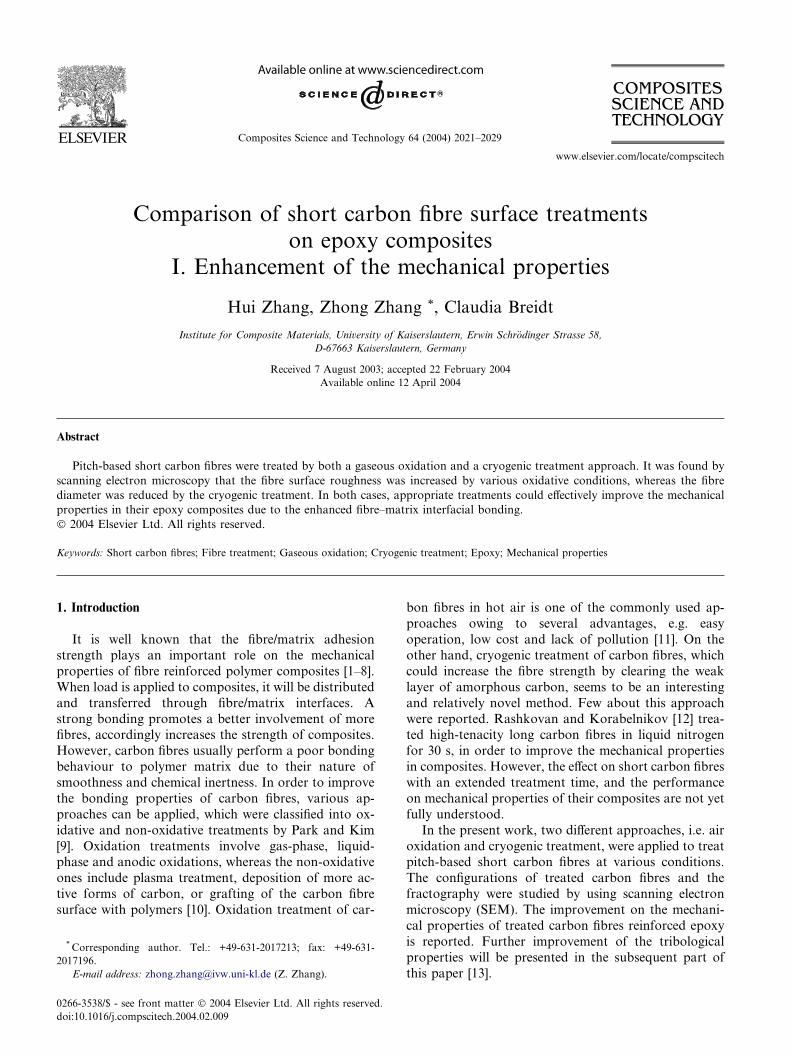
The SEM configurations of as received, oxygen treatedand cryogenic treated short carbon fibres are given in
Fig. 1. Remarkable differences in micrographs can be
observed on untreated and treated carbon fibres. The
surface of as-received fibre (Fig. 1(a)) seems to be rela-
tively smooth and there are some small impurities ab-
sorbed on the fibre surface, which were introduced during
the fibre manufacturing process. Under a treatment
temperature of 450 �C the surface does not look appre-ciably different when compared to untreated ones, which
suggests that the treatment was mild and did not cause
essential morphological changes on the fibre surface [14].
However, by using the gas physical adsorption technique,
Wan et al. [11] reported that after treatment under a
similar condition mentioned above, the total carbon fibre
surface areawas doubled. Their result indicated that some
changes did take place on carbon fibre surface at 450 �C,although it was difficult to be recognized by SEM. Once
the treatment temperature was further increased, the
changes on the surface could be easily observed. At a
treatment temperature of 500 �C for 1 h (Fig. 1(b)), the
fibre surface became relatively rough and more pieces of
tiny fragments stuck to the fibre surface, which suggested
CF volume content Treatment details
15% As-received
15% 450 �C/1 h
15% 500 �C/1 h
15% 550 �C/1 h
15% 600 �C/1 h
15% 1 min
15% 5 min
15% 10 min
15% 20 min
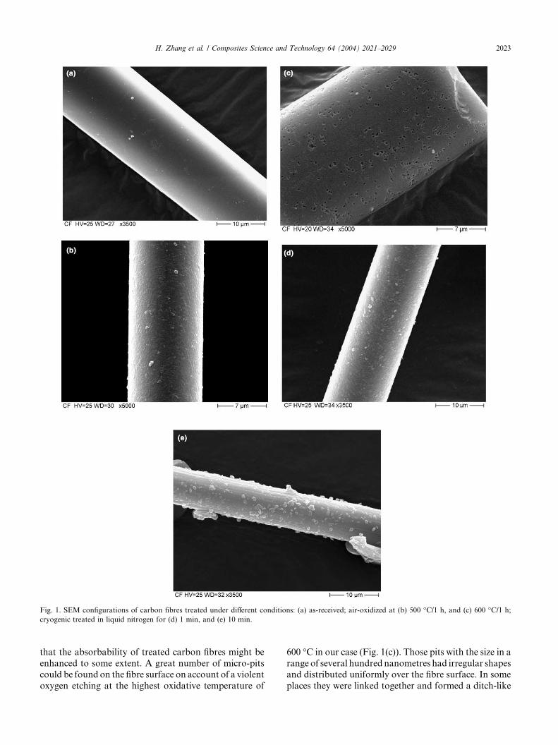
Fig. 1. SEM configurations of carbon fibres treated under different conditions: (a) as-received; air-oxidized at (b) 500 �C/1 h, and (c) 600 �C/1 h;
cryogenic treated in liquid nitrogen for (d) 1 min, and (e) 10 min.
H. Zhang et al. / Composites Science and Technology 64 (2004) 2021–2029 2023
that the absorbability of treated carbon fibres might be
enhanced to some extent. A great number of micro-pits
could be found on the fibre surface on account of a violent
oxygen etching at the highest oxidative temperature of
600 �C in our case (Fig. 1(c)). Those pits with the size in a
range of several hundred nanometres had irregular shapes
and distributed uniformly over the fibre surface. In some
places they were linked together and formed a ditch-like
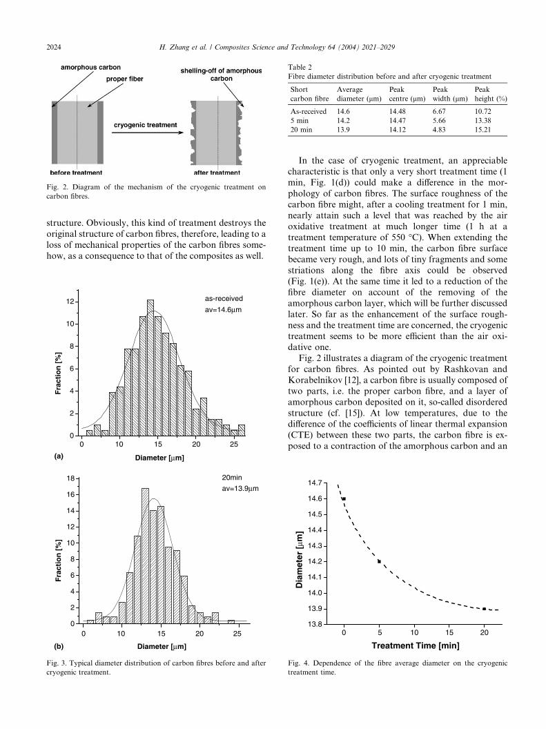
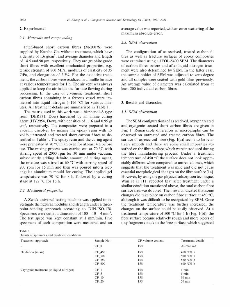
Fig. 2. Diagram of the mechanism of the cryogenic treatment on
carbon fibres.
Table 2
Fibre diameter distribution before and after cryogenic treatment
Short
carbon fibre
Average
diameter (lm)
Peak
centre (lm)
Peak
width (lm)
Peak
height (%)
As-received 14.6 14.48 6.67 10.72
5 min 14.2 14.47 5.66 13.38
20 min 13.9 14.12 4.83 15.21
2024 H. Zhang et al. / Composites Science and Technology 64 (2004) 2021–2029
structure. Obviously, this kind of treatment destroys the
original structure of carbon fibres, therefore, leading to a
loss of mechanical properties of the carbon fibres some-
how, as a consequence to that of the composites as well.
252015100
252015100
0
2
4
6
8
10
12 as-received
av=14.6µm
Fra
ctio
n [
%]
Diameter [µm]
0
2
4
6
8
10
12
14
16
18 20min
av=13.9µm
Fra
ctio
n [
%]
Diameter [µm](b)
(a)
Fig. 3. Typical diameter distribution of carbon fibres before and after
cryogenic treatment.
In the case of cryogenic treatment, an appreciable
characteristic is that only a very short treatment time (1
min, Fig. 1(d)) could make a difference in the mor-
phology of carbon fibres. The surface roughness of the
carbon fibre might, after a cooling treatment for 1 min,
nearly attain such a level that was reached by the air
oxidative treatment at much longer time (1 h at a
treatment temperature of 550 �C). When extending thetreatment time up to 10 min, the carbon fibre surface
became very rough, and lots of tiny fragments and some
striations along the fibre axis could be observed
(Fig. 1(e)). At the same time it led to a reduction of the
fibre diameter on account of the removing of the
amorphous carbon layer, which will be further discussed
later. So far as the enhancement of the surface rough-
ness and the treatment time are concerned, the cryogenictreatment seems to be more efficient than the air oxi-
dative one.
Fig. 2 illustrates a diagram of the cryogenic treatment
for carbon fibres. As pointed out by Rashkovan and
Korabelnikov [12], a carbon fibre is usually composed of
two parts, i.e. the proper carbon fibre, and a layer of
amorphous carbon deposited on it, so-called disordered
structure (cf. [15]). At low temperatures, due to thedifference of the coefficients of linear thermal expansion
(CTE) between these two parts, the carbon fibre is ex-
posed to a contraction of the amorphous carbon and an
0 5 10 15 2013.8
13.9
14.0
14.1
14.2
14.3
14.4
14.5
14.6
14.7
Dia
met
er [
µm]
Treatment Time [min]
Fig. 4. Dependence of the fibre average diameter on the cryogenic
treatment time.
H. Zhang et al. / Composites Science and Technology 64 (2004) 2021–2029 2025
axial expansion of the proper fibre, while the proper fi-
bre has a negative CTE. Shear stresses arise on the in-
terface of the two parts and finally exceed the shear
strength between the proper fibre and the amorphous
carbon layer. Therefore the latter would easily shell offfrom the fibre surface. Due to its heterogeneity, the
amorphous carbon layer shells off along the fibre to
various extents resulting in an increase of the fibre sur-
face roughness, as confirmed by SEM micrographs.
3.2. Fibre diameter distribution
As mentioned above, the amorphous carbon layercan partly shell off from the fibre after the cryogenic
treatment. Accordingly, the diameter of the carbon fibre
is reduced to some degree. Fig. 3 shows the typical
3.5
3.4
3.5
3.5
3.9
3.0
3.5
4.0
4.5
CF_0 CF_450 CF_500 CF_550 CF_600
Fle
xura
l Mo
du
lus
[GP
a]
90.5
109.7107.7
98.1
88.9
80
90
100
110
120
CF_0 CF_450 CF_500 CF_550 CF_600
Fle
xura
l Str
eng
th [
MP
a]
3.473.23.323.333.36
0
1
2
3
4
5
CF_0 CF_450 CF_500 CF_550 CF_600
Elo
ng
atio
n a
t B
reak
[%
]
(a) (d
(e
(f
(b)
(c)
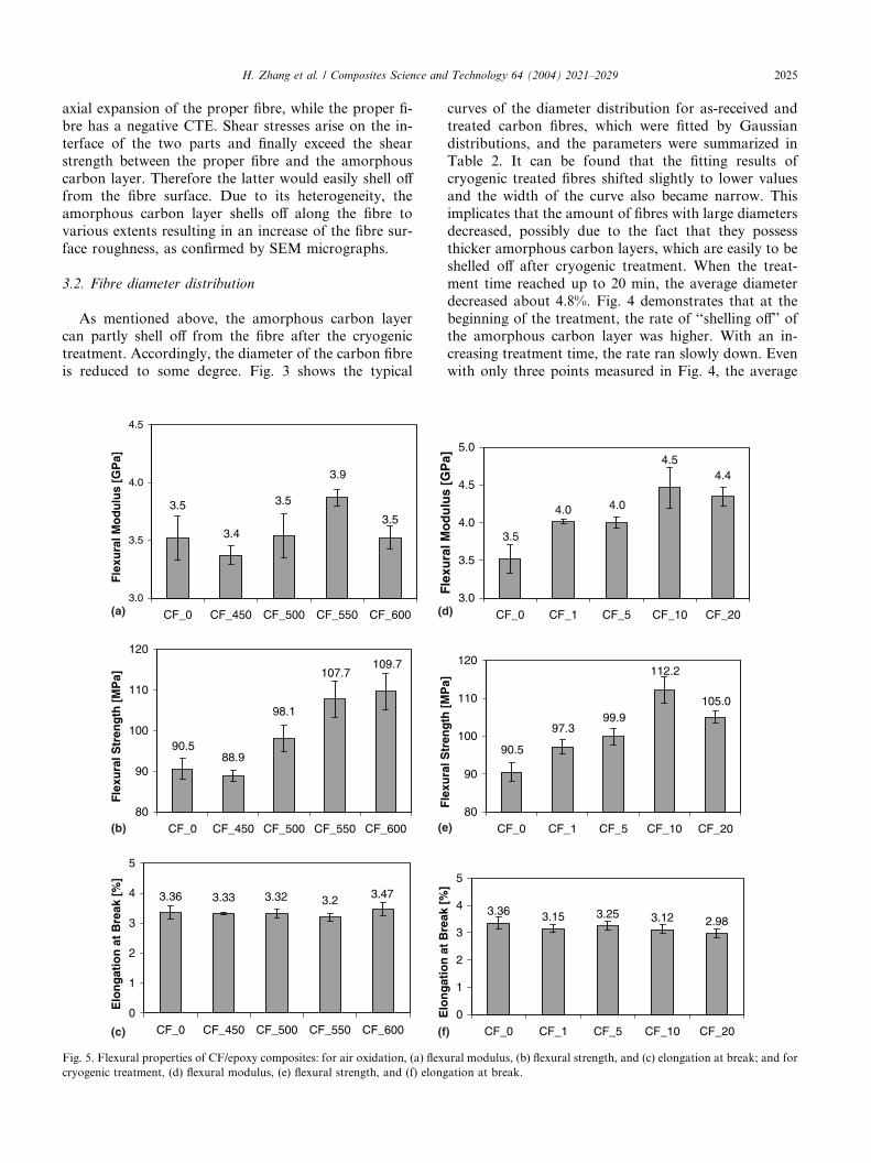
Fig. 5. Flexural properties of CF/epoxy composites: for air oxidation, (a) flex
cryogenic treatment, (d) flexural modulus, (e) flexural strength, and (f) elong
curves of the diameter distribution for as-received and
treated carbon fibres, which were fitted by Gaussian
distributions, and the parameters were summarized in
Table 2. It can be found that the fitting results of
cryogenic treated fibres shifted slightly to lower valuesand the width of the curve also became narrow. This
implicates that the amount of fibres with large diameters
decreased, possibly due to the fact that they possess
thicker amorphous carbon layers, which are easily to be
shelled off after cryogenic treatment. When the treat-
ment time reached up to 20 min, the average diameter
decreased about 4.8%. Fig. 4 demonstrates that at the
beginning of the treatment, the rate of ‘‘shelling off’’ ofthe amorphous carbon layer was higher. With an in-
creasing treatment time, the rate ran slowly down. Even
with only three points measured in Fig. 4, the average
4.0
4.44.5
4.0
3.5
3.0
3.5
4.0
4.5
5.0
CF_0 CF_1 CF_5 CF_10 CF_20
Fle
xura
l Mo
du
lus
[GP
a]
105.0
112.2
90.5
97.399.9
80
90
100
110
120
CF_0 CF_1 CF_5 CF_10 CF_20
Fle
xura
l Str
eng
th [
MP
a]
3.36 3.15 3.25 3.12 2.98
0
1
2
3
4
5
CF_0 CF_1 CF_5 CF_10 CF_20
Elo
ng
atio
n a
t B
reak
[%
]
)
)
)
ural modulus, (b) flexural strength, and (c) elongation at break; and for
ation at break.
CF_0 CF_450 CF_500 CF_550 CF_6000.8
0.9
1.0
1.1
1.2
1.3
1.4
Rel
ativ
e Im
pro
vem
ent
Air Oxidation
flexural modulusflexural strengthelongation
CF_0 CF_1 CF_5 CF_10 CF_200.8
0.9
1.0
1.1
1.2
1.3
1.4
Rel
ativ
e Im
pro
vem
ent
Cryogenic Treatment
flexural modulusflexural strengthelongation
(a)
(b)
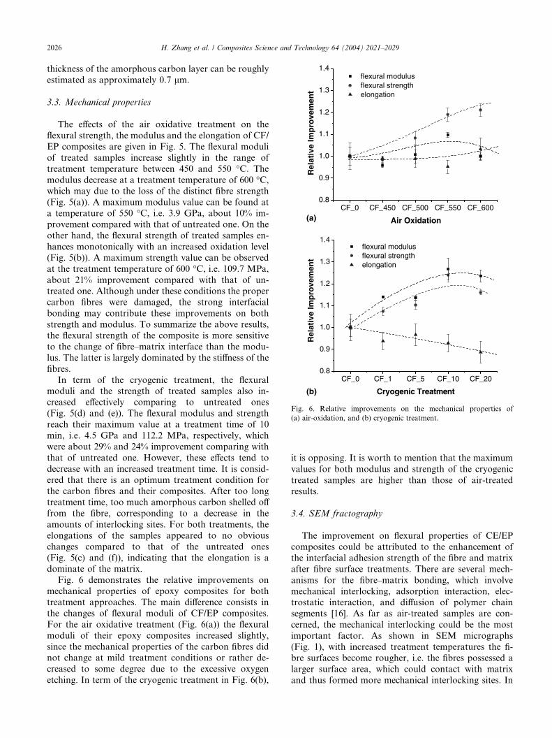
Fig. 6. Relative improvements on the mechanical properties of
(a) air-oxidation, and (b) cryogenic treatment.
2026 H. Zhang et al. / Composites Science and Technology 64 (2004) 2021–2029
thickness of the amorphous carbon layer can be roughly
estimated as approximately 0.7 lm.
3.3. Mechanical properties
The effects of the air oxidative treatment on the
flexural strength, the modulus and the elongation of CF/
EP composites are given in Fig. 5. The flexural moduli
of treated samples increase slightly in the range of
treatment temperature between 450 and 550 �C. The
modulus decrease at a treatment temperature of 600 �C,which may due to the loss of the distinct fibre strength
(Fig. 5(a)). A maximum modulus value can be found ata temperature of 550 �C, i.e. 3.9 GPa, about 10% im-
provement compared with that of untreated one. On the
other hand, the flexural strength of treated samples en-
hances monotonically with an increased oxidation level
(Fig. 5(b)). A maximum strength value can be observed
at the treatment temperature of 600 �C, i.e. 109.7 MPa,
about 21% improvement compared with that of un-
treated one. Although under these conditions the propercarbon fibres were damaged, the strong interfacial
bonding may contribute these improvements on both
strength and modulus. To summarize the above results,
the flexural strength of the composite is more sensitive
to the change of fibre–matrix interface than the modu-
lus. The latter is largely dominated by the stiffness of the
fibres.
In term of the cryogenic treatment, the flexuralmoduli and the strength of treated samples also in-
creased effectively comparing to untreated ones
(Fig. 5(d) and (e)). The flexural modulus and strength
reach their maximum value at a treatment time of 10
min, i.e. 4.5 GPa and 112.2 MPa, respectively, which
were about 29% and 24% improvement comparing with
that of untreated one. However, these effects tend to
decrease with an increased treatment time. It is consid-ered that there is an optimum treatment condition for
the carbon fibres and their composites. After too long
treatment time, too much amorphous carbon shelled off
from the fibre, corresponding to a decrease in the
amounts of interlocking sites. For both treatments, the
elongations of the samples appeared to no obvious
changes compared to that of the untreated ones
(Fig. 5(c) and (f)), indicating that the elongation is adominate of the matrix.
Fig. 6 demonstrates the relative improvements on
mechanical properties of epoxy composites for both
treatment approaches. The main difference consists in
the changes of flexural moduli of CF/EP composites.
For the air oxidative treatment (Fig. 6(a)) the flexural
moduli of their epoxy composites increased slightly,
since the mechanical properties of the carbon fibres didnot change at mild treatment conditions or rather de-
creased to some degree due to the excessive oxygen
etching. In term of the cryogenic treatment in Fig. 6(b),
it is opposing. It is worth to mention that the maximum
values for both modulus and strength of the cryogenic
treated samples are higher than those of air-treated
results.
3.4. SEM fractography
The improvement on flexural properties of CE/EP
composites could be attributed to the enhancement of
the interfacial adhesion strength of the fibre and matrix
after fibre surface treatments. There are several mech-
anisms for the fibre–matrix bonding, which involve
mechanical interlocking, adsorption interaction, elec-trostatic interaction, and diffusion of polymer chain
segments [16]. As far as air-treated samples are con-
cerned, the mechanical interlocking could be the most
important factor. As shown in SEM micrographs
(Fig. 1), with increased treatment temperatures the fi-
bre surfaces become rougher, i.e. the fibres possessed a
larger surface area, which could contact with matrix
and thus formed more mechanical interlocking sites. In
H. Zhang et al. / Composites Science and Technology 64 (2004) 2021–2029 2027
addition, the enhancement of the surface roughness
reduces the contact angle between fibre and matrix and
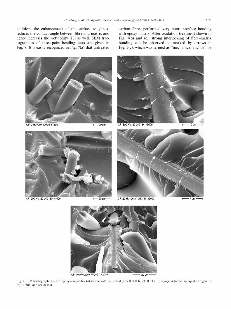
hence increases the wettability [17] as well. SEM frac-
tographies of three-point-bending tests are given in
Fig. 7. It is easily recognized in Fig. 7(a) that untreated
Fig. 7. SEM fractographies of CF/epoxy composites: (a) as-received; oxidized
(d) 10 min, and (e) 20 min.
carbon fibres performed very poor interface bonding
with epoxy matrix. After oxidation treatment shown in
Fig. 7(b) and (c), strong interlocking of fibre–matrix
bonding can be observed as marked by arrows in
Fig. 7(c), which was termed as ‘‘mechanical anchor’’ by
at (b) 500 �C/1 h, (c) 600 �C/1 h; cryogenic treated in liquid nitrogen for
2028 H. Zhang et al. / Composites Science and Technology 64 (2004) 2021–2029
Kalantar and Drzal [16]. The mechanical interlocking
provides a strong interface bonding even though other
effects are weak [18]. Another possible reason for the
enhancement on interfacial adhesion is chemical inter-
action. Many researchers [19–22] have analysed theO1s/C1s ratio of carbon fibre surface by means of a X-
ray photoelectron spectroscopy (XPS), and reported
that gaseous oxidative treatment could increase the
oxygen concentration on carbon fibre surface, which
means that the amount of functional groups could be
increased, e.g. hydroxyl (–OH), carbonyl (–C@O) and
carboxyl (–COOH) groups. These functional groups
may improve the wettability by enhancing the surfaceenergy. Therefore chemical reactions can take place
with epoxy group forming covalent bonding at the
interface.
In the case of cryogenic treatment, similar mechanical
interlocking was also observed which plays an important
role to the improved interfacial adhesion, as shown in
Fig. 7(d) marked by arrows. It is interesting that even
some broken fibres can be found (Fig. 7(e)) which in-dicates the mechanical interlocking in some regions was
very strong. Since the average length of carbon fibres
applied in this study is much shorter compared to the
fibre broken critical length as reported in literatures of
several hundreds microns [23,24], fibre pull-out and
matrix fracture should be the main failure modes in our
case. An improved fibre–matrix bonding with fibre
broken involving will definitely improve the strength ofcomposites. Another reason for the enhancement of the
flexural properties is the strengthening effect of carbon
fibres of the cryogenic treatment [12]. After treatment
the average strength of the carbon fibres usually in-
creased due to the removal of the weak layer and at-
tached particles, which act as concentrators and
decrease the fibre strength to some extent. On the other
hand, it should be mention that not all the carbon fibreshad the similar obvious changes after cryogenic treat-
ment. Some carbon fibres still kept much smoother
surface with poor bonding to the matrix as shown in
Fig. 7(e) as well. The possible reasons of this phenom-
enon could be: (i) the heterogeneity of fibres, while some
carbon fibres, which may possess very thin amorphous
carbon layer, do not form a rough surface after treat-
ment; and (ii) the treatment process, while some fibreswere not effectively treated due to the thermal conduc-
tion. An optimum treatment process is still a task to
fully exert the potential of this approach on the en-
hancement of carbon fibre–matrix bonding of polymer
composites.
4. Conclusions
Based on this work devoted to studying the effect of
surface treatment on mechanical properties of short
carbon fibre reinforced epoxy composites, the following
conclusions can be drawn:
1. Both oxidative and cryogenic treatments could signif-
icantly increase the surface roughness of carbon
fibres, accordingly to improve the interfacial adhe-sion strength of fibre and epoxy bonding due to the
mechanical interlocking.
2. The cryogenic treatment has advantages of very short
treatment time and environment-friendly media, as
well as higher improvement on both modulus and
strength compared to the oxidative one.
3. The carbon fibres used in this study were relatively
short; therefore the improvement on mechanicalproperties was limited. Further enhancement of the
tribological properties will be concentrated on the
subsequent part of this paper [13].
Acknowledgements
Z. Zhang is grateful to the Alexander von Humboldt
Foundation for his Sofja Kovalevskaja Award, financed
by the German Federal Ministry of Education and Re-
search (BMBF) within the German Government’s‘‘ZIP’’ program for investment in the future. The au-
thors appreciate Prof. Dr.-Ing. Dr. h.c. K. Friedrich,
IVW, for his valuable discussions during the course of
this work and the preparation of this paper.
References
[1] Fitzer E, Heine M. Carbon fiber manufacture and surface
treatment. In: Bunsell AR, editor. Fibre reinforcements for
composite materials. Amsterdam, The Netherlands: Elsevier;
1988. p. 124–35 [chapter 3].
[2] Dong S, Gauvin R. Application of dynamic mechanical analysis
for the study of the interfacial region in carbon fiber/epoxy
composite materials. Polym Compos 1993;14:414–20.
[3] Ibarra L, Panos D. Dynamic properties of thermoplastic butadi-
ene-styrene (SBS) and oxidized short carbon fiber composite
materials. J Appl Polym Sci 1998;67:1819–26.
[4] Madhukar MS, Drzal LT. Fiber-matrix adhesion and its effect on
composite mechanical properties. I. Inplane and interlaminar
shear behavior of graphite/epoxy composites. J Compos Mater
1991;25:932–57.
[5] Park BY, Kim SC. A study of the interlaminar fracture
toughness of a carbon-fiber/epoxy composite containing surface-
modified short Kevlar fiber. Compos Sci Technol 1998;58:1599–
606.
[6] Fu X, Chung DDL. Improving the bond strength between carbon
fiber and cement by fiber surface treatment and polymer addition
to cement mix. Cement Concrete Res 1995;25:1391–6.
[7] Blackketter DM, Upadhyaya D, King TR, King JA. Evaluation
of fiber surface treatment and sizing on the shear and transverse
tensile strengths of carbon fiber-reinforced thermoset and
thermoplastic matrix composites. Polym Compos 1993;14:
430–6.
H. Zhang et al. / Composites Science and Technology 64 (2004) 2021–2029 2029
[8] Hughe JDH. The carbon fiber/epoxy interface – a review. Compos
Sci Technol 1991;41:13–45.
[9] Park S-J, Kim M-H. Effect of acidic anode treatment on carbon
fibers for increasing fiber-matrix adhesion and its relationship
to interlaminar shear strength of composites. J Mater Sci
2000;35:1901–5.
[10] Chand S. Review carbon fibers for composites. J Mater Sci
2000;35:1303–13.
[11] Wan YZ, Wang YL, Zhou FG, Chang GX, Han KY.
Three-dimensionally braided carbon fiber-epoxy composites a
new type of materials for osteosynthesis device. II. Influence
of fiber surface treatment. J Appl Polym Sci 2002;85:1040–
6.
[12] Rashkovan IA, Korabelnikov YuG. The effect of fiber surface
treatment on its strength and adhesion to the matrix. Compos Sci
Technol 1997;57:1017–22.
[13] Zhang H, Zhang Z. Comparison of short carbon fibre surface
treatments on epoxy composites. II. Enhancement of the wear
resistance. Compos Sci Technol 2004;64.
[14] Hoffman WP, Hurley WC, Owens TW, Phan HT. Advan-
tage of the scanning tunnelling microscope in documenting
changes in carbon fiber surface morphology brought about
by various surface treatments. J Mater Sci 1991;26:4545–
53.
[15] Yumitori S, Nakanishi Y. Effect of anodic oxidation of coal tar
pitch-based carbon fiber on adhesion in epoxy matrix. Part 1.
Comparison between H2SO4 and NaOH solutions. Composites
Part A 1996;27:1051–8.
[16] Kalantar J, Drzal LT. The bonding mechanism of aramid fibers to
epoxy matrices. Part 1. A review of the literature. J Mater Sci
1990;25:4186–93.
[17] Jang J, Yang H. The effects of surface treatment on the
performance improvement of carbon fiber/polybenzoxazine com-
posites. J Mater Sci 2000;35:2297–303.
[18] Harris B, Braddell OG, Almond DP. Study of carbon fiber surface
treatment by dynamic mechanical analysis. J Mater Sci
1993;28:3353–66.
[19] Boudou JP, Paredes JI, Cuesta A, M-Alonso A, Tascon JM.
Oxygen plasma modification of pitch-based isotropic carbon
fibers. Carbon 2003;41:41–56.
[20] Lee J-S, Kang TJ. Changes in physic-chemical and morphological
properties of carbon fiber by surface treatment. Carbon
1997;35:209–16.
[21] Fu R, Liu L, Huang W, Sun P-C. Studies on the structure of
activated carbon fibers activated by phosphoric acid. J Appl
Polym Sci 2003;87:2253–61.
[22] Shin S, Jang J, Yoon S-H, Mochida I. A study on the effect of heat
treatment on functional groups of pitch based activated carbon
fiber using FTIR. Carbon 1997;35:1743–93.
[23] Netravali AN, Li Z-F, Sachse W, Wu HF. Determination of fiber/
matrix interfacial shear strength by an acoustic emission tech-
nique. J Mater Sci 1991;26:6631–8.
[24] Fjeldly A, Olsen T, Rysjedal JH, Berg JE. Influence of the fiber
surface treatment and hot-wet environment on the mechanical
behaviour of carbon/epoxy composites. Composites Part A
2001;32:373–8.