Embed Size (px)
Citation preview
13th World Conference on Earthquake Engineering Vancouver, B.C., Canada
August 1-6, 2004 Paper No. 3168
COMPARISON OF SEISMIC CODES OF 1981 JAPAN (BSLJ), 2000 USA (IBC) AND 1999 IRAN (ICS)
Marjan FAIZIAN1 and Yuji ISHIYAMA2
SUMMARY Most seismic codes require that structures be designed to resist specified static lateral forces related to the structure and the seismicity of the region. Based on an estimate of the fundamental natural period of the structure, formulas are specified for the base shear and the distribution of lateral forces over height of the buildings. These seismic design provisions in three building codes, 1981 Japan (BSLJ), 2000 USA (IBC) and 1999 Iran (2800), and their similarities and differences are presented in the paper. At first, the codes and their backgrounds are introduced and the design procedures in these three are described. Then for calculating the seismic load in each code the base shear coefficient, seismic zoning, spectral content, fundamental period, structural behavior coefficient, importance factor, effect of soil profile and foundation, and effect of the weight of buildings are precisely discussed and the differences have been mentioned. After calculating the seismic force, the distribution methods over the height of the building and also the torsion and the base shear coefficients are compared. In the next step, the other considerations in these codes such as story drift limitations and overturning moment reduction coefficients are discussed. At last, the dynamic analysis methods, which in all three codes are only necessary for irregular and unusual buildings, as described in the codes, are taken into consideration. Although these three codes differ in details, they have a lot of common features which can be compared. This comparison shows that the Iranian seismic code is very similar to the Americans but the Japanese code is considerably different from the other two codes.
INTRODUCTION Earthquakes all over the world have affected the seismic resistant design in different countries and made a revision necessary in many areas. Great improvements during last 50 years in Japan and USA make a comparison between their codes and other countries’ inevitable. The Building Standard Law in Japan (BSLJ) has been in force since 1950 (after World War II) to safeguard the lives, health and property of people, and to increase the public safety. The current seismic design method comprises the revised
1 PHD candidate, Swiss Federal Institute of Technology, Zurich, Switzerland. Email: [email protected] (Former: Master student in Hokkaido University, Japan) 2 Professor, Graduate school of Engineering, Hokkaido University, Sapporo, Japan. Email: [email protected]
enforcement order, notifications and related regulations in force since 1981 under the Building Standard Law. The regulations were issued after a five-year national research project to develop new seismic design methods and a three-year review. (There is a new version of the Japanese seismic code published in 2000 which is not included in this paper. The regulations since 1981 are still valid. Therefore the new version is considered to be an additional procedure to the current routes.) The 2000 edition of the International Building Code of USA (IBC) is based on the previous code (NEHRP) and contains the results of additional research. This edition is intended to serve as a source document for use by any interested member of the building community and in particular for the development of seismic provisions through out the USA. Occurrence of the 20 June 1990 Manjil, Iran, Earthquake was indeed a breakthrough in the earthquake related activities in Iran, from research to practice, and from earthquake hazard mitigation planning to improving seismic code (ICS). The earthquake also called the attention of the public as well as the authorities of the country. This event accompanied with the International Decade for Natural Disaster Reduction (IDNDR) and consequently various institutes and organizations became involved in conducting relevant research projects and studies. Existing organizations became more active in reducing earthquake induced disasters. At least two centers and several committees were established to have a more effective coverage of the various aspects of the earthquake hazard reduction programs. National Disaster Prevention Center (NDPC) and Center for Earthquake Studies of Tehran (CEST) are among the recently established centers whose main job at the first step was to revise the Iranian Code for Seismic Resistance Design of Buildings (ICS). In 1999, using this revised edition became necessary for all the engineers who were involved in designing buildings.
DESIGN PROCEDURE In the BSLJ design procedure, the stresses on structural members, caused by lateral seismic shear for the moderate earthquake motions, are calculated and the members are designed for the load combinations of permanent load and seismic load, using working stress design method (TABLE 1). Also, for buildings higher than 31 m and for irregular buildings, calculating the ultimate lateral shear strength of each story above the ground is required and confirmed that can not be less than the specified ultimate lateral shear for severe earthquake motions. Buildings exceeding 60 meters in height require special permission from the ministry of land, infrastructure and transport following a detailed review of the dynamic behavior of the structure by the board of technical members. In IBC, for both allowable stress design and strength design methods, where specifically required, elements and components shall be designed to resist the forces due to TABLE 1, first formula in IBC, when the effects of the seismic ground motion are additive to gravity forces and second formula, when the effects of the seismic ground motion counteract gravity forces. In the ICS, the forces in structural members are calculated due to the subjected loads and then designed with working stress design (W.S.D) for steel structures and limit state design (L.S.D) in case of concrete structures under different load combinations (TABLE 1).
Table 1: Load combinations for seismic design
Code Load Combination 1 Load Combination 2 BSLJ D + L + E D + L + S + E IBC 1.2 D + f1 L + Em 0.9 D + Em ICS D + 1.20 L + 1.2 E 0.85 D + 1.20 E
D: dead load, E: seismic load, L: live load, S: snow load, Em: max seismic load effect, f1: coefficient equal to 0.5 or 1.0 for different live loads
Base shear coefficient In BSLJ, the lateral seismic shear coefficient for moderate earthquake motions is determined with Eqn. 1, where Z is the seismic zoning coefficient, Rt is the design spectral coefficient, Ai is the lateral shear distribution factor and C0 is the standard shear coefficient = 0.2 and for severe earthquake motions with Eqn. 2, where Ds is the structural coefficient, Fes is the shape factor and C0 = 1.0.
Ci = Z Rt Ai C0 (1) CB = DS Fes Z Rt C0 (2)
For IBC the seismic response coefficient shall be determined in accordance with Eqn. 3.
=
E
DSS
IR
SC
(3) Where IE is the occupancy importance factor, R is the response modification factor and SDS is the design spectral response acceleration at short period. The value of seismic response coefficient, Cs, computed in accordance with Eqn. 3 need not exceed Eqn. 4 and not less than Eqn. 5 or in some cases Eqn. 6, where, SDI is the design spectral acceleration at 1-second period, S1 is the maximum considered earthquake spectral response at 1-second period and T is the fundamental period of the building.
TIRS
C
E
DIS
≤ (4)
CS ≥ 0.044 SDS IE (5)
≥
E
1S
IR
0.5SC (6)
The base shear coefficient CB for ICS:
RIBACB = (7)
Where A is the design base acceleration in g, B is the response coefficient of the building, I is the importance factor and R is the behavior coefficient of the building. The CB value obtained from Eqn. 7 shall in no case be less than 10% of the design base acceleration. Seismic zoning The BSLJ seismic zoning map in Figure 1 only indicates the relative seismicity, dividing Japan into three zones. The seismic zoning coefficient Z is 1.0, 0.9,0.8 and 0.7. It is not explained how these values are related to acceleration or to velocity nor is the return period specifically stated. By means of the standard shear coefficient C0, two levels of seismic risk are addressed: C0 = 0.2 for moderate earthquake motions and 1.0 for severe earthquake motions. Which indicates the maximum ground acceleration is 0.08g for moderate earthquake motions and 0.4g for severe earthquake motions, assuming the magnification factor for short period a structure is 2.5 to the ground.
SEISMIC LOAD
Figure 1: Seismic hazard zoning coefficient Z (BSLJ)
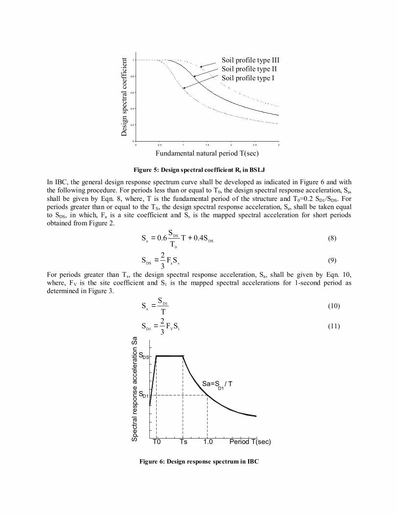
In IBC, the mapped maximum considered earthquake spectral response acceleration at short periods, SS, and at 1-second period, S1, shall be determined from Figures 2 and 3. The seismic zoning map in ICS, Figure 4, only indicates similar parts, dividing Iran to three zones. The design base acceleration A is 0.35, 0.25 and 0.20 for the high, intermediate and low seismic relative hazard.
Figure 2: Max considered earthquake ground motion for the conterminous united states of 0.2 sec spectral
response acceleration

Figure 3: Max considered earthquake ground motion for the conterminous united states of 1.0 sec spectral
response acceleration
Figure 4: Seismic hazard zoning in Iran (ICS)
Spectral Content In BSLJ, the design spectral factor coefficient, Rt, is determined with the help of the TABLE 2 and Figure 5, where T is the fundamental natural period of the building and Tc is critical period, which is equal to 0.4, 0.6 and 0.8 for soil profiles type I, II and III.
Table 2: DESIGN SPECTRAL COEFFICIENT RT (BSLJ)
T T < Tc Tc<T<2Tc 2Tc < T
Rt 1 2
12.01
−−
cTT
TTc6.1
0
0.2
0.4
0.6
0.8
1
0 0.5 1 1.5 2 2.5 3
Fundamental natural period T(sec)
Des
ign
spec
tral c
oeff
icie
nt Soil profile type III Soil profile type II Soil profile type I
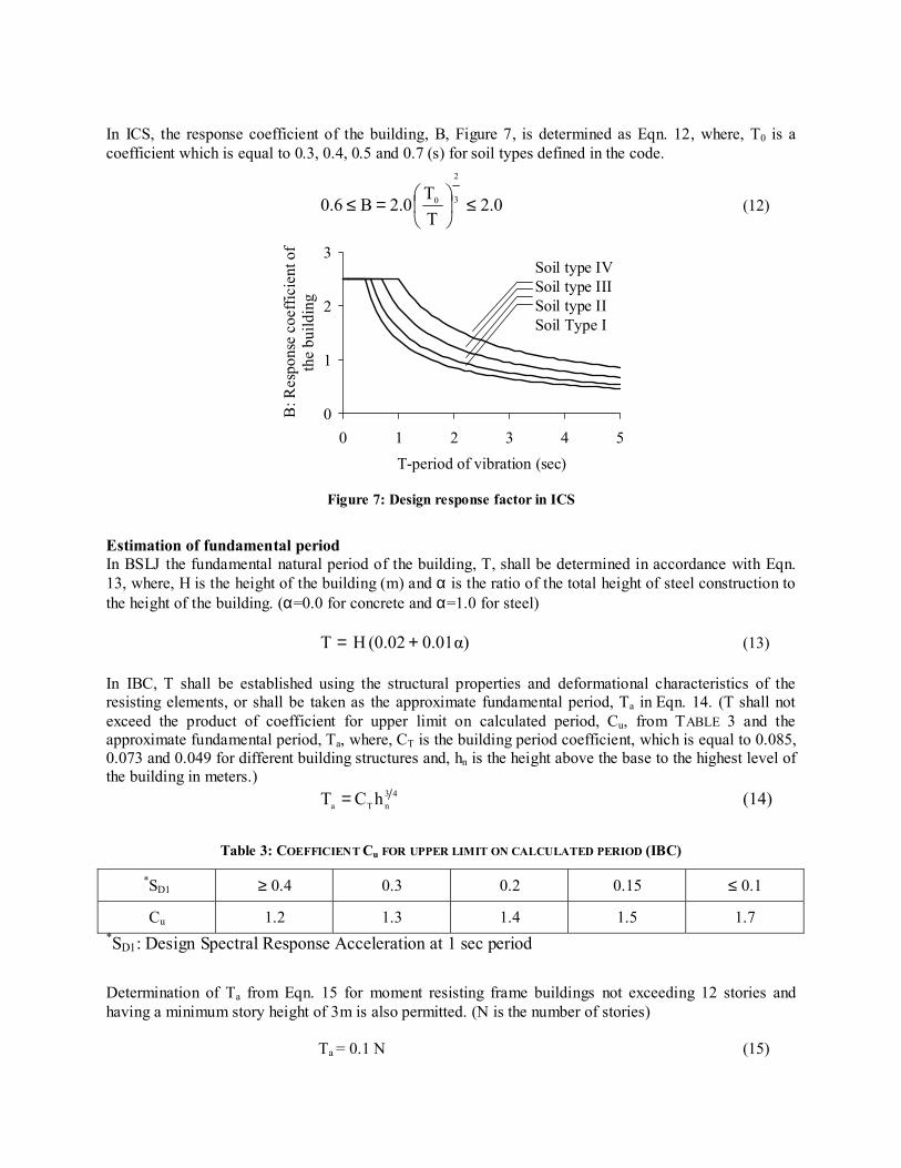
Figure 5: Design spectral coefficient Rt in BSLJ
In IBC, the general design response spectrum curve shall be developed as indicated in Figure 6 and with the following procedure. For periods less than or equal to T0, the design spectral response acceleration, Sa, shall be given by Eqn. 8, where, T is the fundamental period of the structure and T0=0.2 SD1/SDS. For periods greater than or equal to the TS, the design spectral response acceleration, Sa, shall be taken equal to SDS, in which, Fa is a site coefficient and Ss is the mapped spectral acceleration for short periods obtained from Figure 2.
DS0
DSa 0.4ST
TS
0.6S += (8)
saDS SF32S = (9)
For periods greater than Ts, the design spectral response acceleration, Sa, shall be given by Eqn. 10, where, FV is the site coefficient and S1 is the mapped spectral accelerations for 1-second period as determined in Figure 3.
TS
S D1a = (10)
1VD1 SF32S = (11)
Period T(sec)Spec
tral r
espo
nse
acce
lera
tion
Sa
T0 Ts 1.0
SD1
SDS
Sa=SD1
/ T
Figure 6: Design response spectrum in IBC
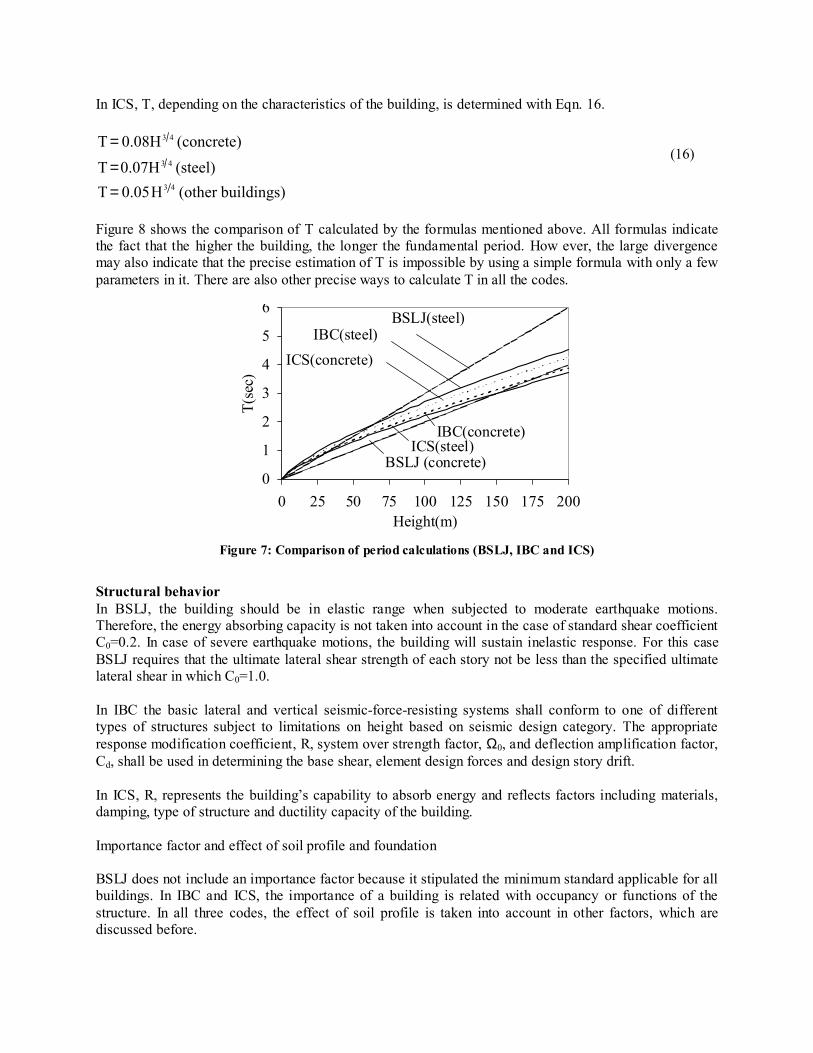
In ICS, the response coefficient of the building, B, Figure 7, is determined as Eqn. 12, where, T0 is a coefficient which is equal to 0.3, 0.4, 0.5 and 0.7 (s) for soil types defined in the code.
2.0TT
2.0B0.6 3
2
0 ≤
=≤ (12)
0
1
2
3
0 1 2 3 4 5T-period of vibration (sec)
B: R
espo
nse
coef
ficie
nt o
f th
e bu
ildin
g
Soil type IVSoil type IIISoil type IISoil Type I
Figure 7: Design response factor in ICS
Estimation of fundamental period In BSLJ the fundamental natural period of the building, T, shall be determined in accordance with Eqn. 13, where, H is the height of the building (m) and α is the ratio of the total height of steel construction to the height of the building. (α=0.0 for concrete and α=1.0 for steel)
α)0.01(0.02HT += (13) In IBC, T shall be established using the structural properties and deformational characteristics of the resisting elements, or shall be taken as the approximate fundamental period, Ta in Eqn. 14. (T shall not exceed the product of coefficient for upper limit on calculated period, Cu, from TABLE 3 and the approximate fundamental period, Ta, where, CT is the building period coefficient, which is equal to 0.085, 0.073 and 0.049 for different building structures and, hn is the height above the base to the highest level of the building in meters.)
43nTa hCT = (14)
Table 3: COEFFICIENT Cu FOR UPPER LIMIT ON CALCULATED PERIOD (IBC)
*SD1 ≥ 0.4 0.3 0.2 0.15 ≤ 0.1
Cu 1.2 1.3 1.4 1.5 1.7 *SD1: Design Spectral Response Acceleration at 1 sec period
Determination of Ta from Eqn. 15 for moment resisting frame buildings not exceeding 12 stories and having a minimum story height of 3m is also permitted. (N is the number of stories)
Ta = 0.1 N (15)
In ICS, T, depending on the characteristics of the building, is determined with Eqn. 16.
(steel)0.07HT(concrete)0.08HT
43
43
==
(16)
buildings)(otherH0.05T 43= Figure 8 shows the comparison of T calculated by the formulas mentioned above. All formulas indicate the fact that the higher the building, the longer the fundamental period. How ever, the large divergence may also indicate that the precise estimation of T is impossible by using a simple formula with only a few parameters in it. There are also other precise ways to calculate T in all the codes.
0
1
2
3
4
5
6
0 25 50 75 100 125 150 175 200Height(m)
T(se
c)
BSLJ (concrete)
BSLJ(steel)
ICS(steel)IBC(concrete)
ICS(concrete)IBC(steel)
Figure 7: Comparison of period calculations (BSLJ, IBC and ICS)
Structural behavior In BSLJ, the building should be in elastic range when subjected to moderate earthquake motions. Therefore, the energy absorbing capacity is not taken into account in the case of standard shear coefficient C0=0.2. In case of severe earthquake motions, the building will sustain inelastic response. For this case BSLJ requires that the ultimate lateral shear strength of each story not be less than the specified ultimate lateral shear in which C0=1.0. In IBC the basic lateral and vertical seismic-force-resisting systems shall conform to one of different types of structures subject to limitations on height based on seismic design category. The appropriate response modification coefficient, R, system over strength factor, Ω0, and deflection amplification factor, Cd, shall be used in determining the base shear, element design forces and design story drift. In ICS, R, represents the building’s capability to absorb energy and reflects factors including materials, damping, type of structure and ductility capacity of the building. Importance factor and effect of soil profile and foundation BSLJ does not include an importance factor because it stipulated the minimum standard applicable for all buildings. In IBC and ICS, the importance of a building is related with occupancy or functions of the structure. In all three codes, the effect of soil profile is taken into account in other factors, which are discussed before.
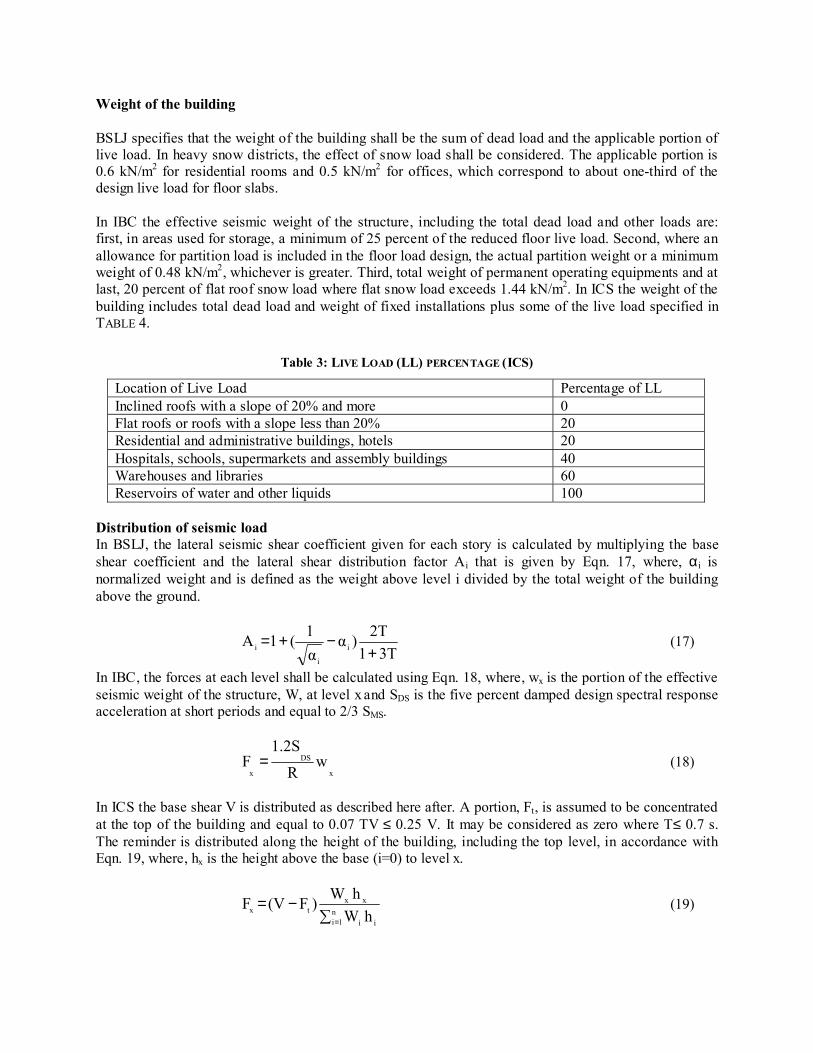
Weight of the building BSLJ specifies that the weight of the building shall be the sum of dead load and the applicable portion of live load. In heavy snow districts, the effect of snow load shall be considered. The applicable portion is 0.6 kN/m2 for residential rooms and 0.5 kN/m2 for offices, which correspond to about one-third of the design live load for floor slabs. In IBC the effective seismic weight of the structure, including the total dead load and other loads are: first, in areas used for storage, a minimum of 25 percent of the reduced floor live load. Second, where an allowance for partition load is included in the floor load design, the actual partition weight or a minimum weight of 0.48 kN/m2, whichever is greater. Third, total weight of permanent operating equipments and at last, 20 percent of flat roof snow load where flat snow load exceeds 1.44 kN/m2. In ICS the weight of the building includes total dead load and weight of fixed installations plus some of the live load specified in TABLE 4.
Table 3: LIVE LOAD (LL) PERCENTAGE (ICS)
Location of Live Load Percentage of LL Inclined roofs with a slope of 20% and more 0 Flat roofs or roofs with a slope less than 20% 20 Residential and administrative buildings, hotels 20 Hospitals, schools, supermarkets and assembly buildings 40 Warehouses and libraries 60 Reservoirs of water and other liquids 100
Distribution of seismic load In BSLJ, the lateral seismic shear coefficient given for each story is calculated by multiplying the base shear coefficient and the lateral shear distribution factor Ai that is given by Eqn. 17, where, α i is normalized weight and is defined as the weight above level i divided by the total weight of the building above the ground.
3T1
2T)αα1(1A i
i
i +−+= (17)
In IBC, the forces at each level shall be calculated using Eqn. 18, where, wx is the portion of the effective seismic weight of the structure, W, at level x and SDS is the five percent damped design spectral response acceleration at short periods and equal to 2/3 SMS.
x
DS
xw
R
1.2SF = (18)
In ICS the base shear V is distributed as described here after. A portion, Ft, is assumed to be concentrated at the top of the building and equal to 0.07 TV ≤ 0.25 V. It may be considered as zero where T≤ 0.7 s. The reminder is distributed along the height of the building, including the top level, in accordance with Eqn. 19, where, hx is the height above the base (i=0) to level x.
∑−=
=n
1i ii
xxtx hW
hW)F(VF (19)
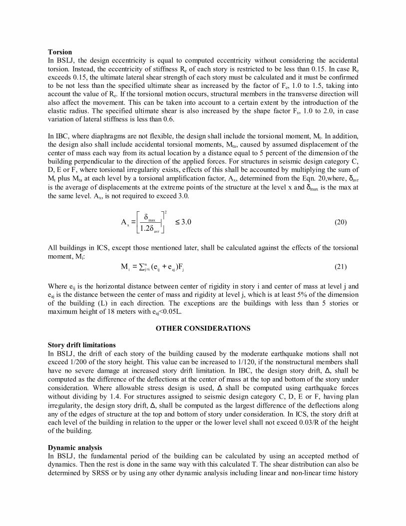
Torsion In BSLJ, the design eccentricity is equal to computed eccentricity without considering the accidental torsion. Instead, the eccentricity of stiffness Re of each story is restricted to be less than 0.15. In case Re exceeds 0.15, the ultimate lateral shear strength of each story must be calculated and it must be confirmed to be not less than the specified ultimate shear as increased by the factor of Fe, 1.0 to 1.5, taking into account the value of Re. If the torsional motion occurs, structural members in the transverse direction will also affect the movement. This can be taken into account to a certain extent by the introduction of the elastic radius. The specified ultimate shear is also increased by the shape factor Fs, 1.0 to 2.0, in case variation of lateral stiffness is less than 0.6. In IBC, where diaphragms are not flexible, the design shall include the torsional moment, Mt. In addition, the design also shall include accidental torsional moments, Mta, caused by assumed displacement of the center of mass each way from its actual location by a distance equal to 5 percent of the dimension of the building perpendicular to the direction of the applied forces. For structures in seismic design category C, D, E or F, where torsional irregularity exists, effects of this shall be accounted by multiplying the sum of Mt plus Mta at each level by a torsional amplification factor, Ax, determined from the Eqn. 20,where, δavr is the average of displacements at the extreme points of the structure at the level x and δmax is the max at the same level. Ax, is not required to exceed 3.0.
3.01.2δδA
2
avr
maxx ≤
= (20)
All buildings in ICS, except those mentioned later, shall be calculated against the effects of the torsional moment, Mi:
∑ += =n
ij jajiji )Fe(eM (21) Where eij is the horizontal distance between center of rigidity in story i and center of mass at level j and eaj is the distance between the center of mass and rigidity at level j, which is at least 5% of the dimension of the building (L) in each direction. The exceptions are the buildings with less than 5 stories or maximum height of 18 meters with eaj<0.05L.
OTHER CONSIDERATIONS Story drift limitations In BSLJ, the drift of each story of the building caused by the moderate earthquake motions shall not exceed 1/200 of the story height. This value can be increased to 1/120, if the nonstructural members shall have no severe damage at increased story drift limitation. In IBC, the design story drift, ∆, shall be computed as the difference of the deflections at the center of mass at the top and bottom of the story under consideration. Where allowable stress design is used, ∆ shall be computed using earthquake forces without dividing by 1.4. For structures assigned to seismic design category C, D, E or F, having plan irregularity, the design story drift, ∆, shall be computed as the largest difference of the deflections along any of the edges of structure at the top and bottom of story under consideration. In ICS, the story drift at each level of the building in relation to the upper or the lower level shall not exceed 0.03/R of the height of the building. Dynamic analysis In BSLJ, the fundamental period of the building can be calculated by using an accepted method of dynamics. Then the rest is done in the same way with this calculated T. The shear distribution can also be determined by SRSS or by using any other dynamic analysis including linear and non-linear time history
analysis. Because BSLJ applies only to buildings less than 60 meters in height, dynamic analysis are required for all buildings higher than 60 meters and the approval of the minister of land, infrastructure and transport must be obtained. In IBC, the following three dynamic analysis procedures performed. Modal Response Spectra Analysis, Linear Time-History Analysis and Nonlinear Time-History Analysis. In ICS, a dynamic analysis is required in regular buildings with the height more than 50 meters and irregular buildings in plan, stiffness and T. There are two ways, one Pseudo-Dynamic Analysis method with the use of modal analysis (SRSS, or CQC) and design response spectrum and the other, Time- History Analysis with the use of accelerograms.
SUMMARY AND CONCLUSIONS The main factors, which constitute the seismic load provisions of ICS, BSLJ and IBC, have been presented and compared. While the three codes differ in detail, they have essential common features and are comparable. The ICS is quit similar to IBC, but there is difference between these two and Japanese BSLJ. All of them include the effect of seismic risk, spectral contents, structural behavior and soil/foundation for seismic load. The importance of a building is included in ICS and IBC but not in BSLJ. The other compared effects are torsion, story drift limitation and dynamic analysis.
REFRENCES
1. Ishiyama Y. and Rainer J. Hans. Comparison of seismic provisions of 1985 NBC of Canada, 1981 BSL of Japan and 1985 NEHRP of the USA. 5th Canadian conference, earthquake engineering, Ottawa, 1987.
2. Ishiyama Y. Seismic Design Method for Buildings in Japan. Comparison of building design practices in the U.S. and Japan, ATC 15, Applied Technology Council, 1984.
3. Regulations for Seismic design, a world list, IAEE,1996 4. Ishiyama Y. Japanese seismic design method and its history. Third US–Japan workshop on the
improvement of building structural design and construction practice, ATC15-2, 1989. 5. Regulations for Seismic design, a world list, 1996, Supplement2000, IAEE. 6. International Code Council. International Building Code of USA, 2000. 7. Anil. K. Chopra. Dynamics of structures. Prentice hall, 2000. 8. Building and housing research center, Iranian code for seismic resistant design, 1999.