Embed Size (px)
Citation preview

American Institute of Aeronautics and Astronautics
1
Comparing Trash Disposal and Reuse Options for Deep
Space Gateway and Mars Missions
Michael Ewert1 and James Broyan2
NASA Johnson Space Center, Houston, Texas, 77058
and
Kandyce Goodliff3, Martha Clowdsley4, and Robert Singleterry5
NASA Langley Research Center, Hampton, Virginia, 23681
Taking out the trash at NASA’s newly proposed Deep Space Gateway (DSG) will not be a
trivial task. While not the most important aspect of planning this cislunar outpost, there are
several options that should be carefully considered since they may affect the crew as well as
mission mass and volume. This study extends an earlier one, which focused on waste disposal
options for a Mars Transit Vehicle. In that study, gasifying and venting trash along the way
was found to noticeably reduce propellant needs and launch mass, whereas keeping
processed trash on board in the form of radiation shielding tiles would significantly lower
the crew’s radiation dose during a solar particle event. Another favorable strategy was
packing trash in a used logistics module for disposal.
Since the DSG does not need much propulsion to maintain its orbit and Orion will be
present with its own radiation storm shelter at the Gateway, the driving factors of the waste
disposal trade study are different than for the Mars mission. Besides reviewing the
propulsion and radiation shielding factors, potential drivers such as mass, power, volume,
crew time, and human factors (e.g. smell) were studied. Disposal options for DSG include
jettison of a used logistics module containing waste after every human stay, jettison of the
same logistics module after several missions once it is full, regular disposal of trash via an
airlock, or gasifying waste products for easier disposal or reuse. Conversely, a heat melt
compactor device could be used to remove water and stabilize trash into tiles which could be
more compactly stored on board and used as radiation shielding.
Equivalent system mass analysis is used to tally the benefits and costs (mass, volume,
power, crew time) of each case on an equivalent mass basis. Other more subjective factors
are also discussed. Recommendations are made for DSG and Mars mission waste disposal.
Nomenclature
ALARA = as low as reasonably achievable
BFO = blood forming organs
Δ = difference
DSG = Deep Space Gateway
DST = Deep Space Transport
EM = exploration mission
ESM = equivalent system mass
GCR = galactic cosmic radiation
HMC = Heat Melt Compactor
ISS = International Space Station
1 Life Support and Thermal Systems Analyst, Crew & Thermal Systems Division, 2101 NASA Parkway. 2 Logistics Reduction Project Manager, Crew & Thermal Systems Division, 2101 NASA Parkway, AIAA Member. 3 Aerospace Engineer, Space Missions Analysis Branch, MS 462, AIAA Senior Member. 4 Physicist, Durability, Damage Tolerance, and Reliability Branch, MS188E. 5 Aerospace Engineer, Durability, Damage Tolerance, and Reliability Branch, MS188E.
https://ntrs.nasa.gov/search.jsp?R=20170007947 2018-05-08T07:16:05+00:00Z

American Institute of Aeronautics and Astronautics
2
LEO = low Earth orbit
MTV = Mars Transit Vehicle
NHV = net habitable volume
PEL = permissible exposure limit
RBE = relative biological effectiveness
SEP = solar electric propulsion
SPE = solar particle event
TtG = Trash-to-gas
I. Introduction
any details must be carefully considered to successfully plan human missions into deep space, including what
to do with the trash. Eventually it will be beneficial if trash and other waste products can be recycled and
reused on the mission, but various factors may make that difficult on early missions. NASA has on-going mission
studies as well as technology development programs to support future exploration missions. This paper builds upon
prior work and explores the options for dealing with trash in a cislunar Deep Space Gateway (DSG), while keeping
an eye toward Mars missions and the technologies that will be needed there.
In 2014, Ref. 1 considered solid waste disposal from human missions at Earth-moon libration points and on the
way to Mars, focusing on small airlock and trash-to-gas (TtG) jettison options. The authors concluded that the trash-
to-gas option was preferred for both mission types, citing the large number of airlock operations that would be
needed and the benefits of using produced gases in resistojets to offset station keeping propellant needs.
In 2017, Ref. 2 evaluated five different trash disposal options for a Mars transit vehicle (MTV), adding use of a
disposable logistics module, long term storage, and use of a heat melt compactor (HMC) device to those considered
by Ref. 1. This current study augments that work by adding additional evaluation criteria and extends it to a DSG
type mission. In the earlier Mars mission study, mass and propulsion analysis illustrated that both the space
transportation architecture and the trash disposal strategy (or lack thereof) had a significant effect on total launch
mass. For the hybrid propulsion system, which was found to be more efficient that the split SEP/Chemical system,
the lowest launch mass options were use of a separate logistics module and use of trash-to-gas technology, as shown
in Table 1. Compared to reference case C, it can be seen that even though more mass had to be launched initially in
case A, the propulsion system mass was quite a bit lower since the logistics module could be dropped prior to the
burn returning the crew to Earth. On the other hand, even though case D had very similar mass to launch, the
propulsion system was much heavier since all trash was kept on board in this case. Radiation analysis showed that
draft minimum requirements for solar particle event (SPE) shielding could be met without any additional shielding
than the spacecraft and its onboard logistics. However, the analysis also demonstrated that creating a storm shelter
prior to a SPE could greatly reduce the astronaut’s radiation dose, especially when HMC technology was used to
create radiation shielding tiles. While the mass of the equipment to deal with trash was included in the previous
study, other factors such as the volume, power, cooling and crew time they require were not. The current study
includes those factors as well as resources that may be recoverable from the trash.
Table 1. Propulsion mass analysis results from prior Mars Transit study (Ref. 2).
Hybrid Case Hab+LM+
Logistics
(kg)
Trash Equip.+
consumables
(kg)
Total to
launch
(kg)
D to launch
vs. case C
(kg)
D propulsion
sys. vs. case
C (kg)
Total stack
launch mass
(kg)
Log module A 44,547 25 44,572 1,111 -1730 111,402
Trash-lock B 43,295 538 43,833 372 800 113,193
Trash-to-gas C 43,295 166 43,461 0 0 112,021
Storage D 43,295 223 43,518 57 6810 118,888
HMC E 43,295 144 43,439 -22 2550 114,549
II. Background
A. Gateway Missions
NASA’s exploration plan beyond low Earth orbit (LEO) assumes a phased approach. Fig. 1 presents these
phases along with time frames of achieving the phases, as presented at the NASA Advisory Council March 30-31,
M

American Institute of Aeronautics and Astronautics
3
2017 Public Meeting3. Phase 0 utilizes the International Space Station (ISS) for testing in support of human
exploration beyond LEO. Phases 1 and 2 focus on the lunar vicinity to conduct cislunar missions, assembly of the
Deep Space Gateway (DSG) and Deep Space Transport (DST), and verification that the DST is ready for Mars.
Phases 3 and 4 leverage knowledge gained in the previous phases to enable missions to the Mars vicinity and
surface. The prior Mars transit study (Ref. 2) was applicable to phase 3. The current DSG analysis is applicable to
phase 1, where several options are considered for analysis purposes.
Figure 1. NASA’s phased approach to exploration3.
The focus of phase 1 is the assembly of the DSG and conducting missions in cislunar space. The DSG is a small
crew-tended facility, able to support crews of four for up to 30 days. As shown in Fig. 2, this instantiation of the
DSG consists of a power/propulsion bus, habitation, and logistics elements. Mission durations in the figure include
transit time in addition to the stay at DSG. An airlock may also be added to the DSG to enhance capabilities of the
facility. Each of the DSG elements will be launched as co-manifested payload with the Orion spacecraft on the
Space Launch System (SLS). NASA is working with commercial and international partners to understand the best
options for buildup of DSG and the elements included to support future beyond-LEO exploration and science
objectives. Other instantiations of DSG using additional logistics launches are also being used in NASA studies, so
care should be taken to understand the DSG definition prior to comparing these results directly to other studies.
Based on the proposed buildup in Fig. 2, the power/propulsion bus will be launched first. This bus is envisioned
as a 40 kW solar electric propulsion (SEP) system augmented with a chemical reaction control system. The bus will
provide power to the DSG elements throughout their lifetime. The habitat will augment Orion’s current capabilities
and allow for extended crew visits of up to 30 days while Orion is docked. For each visit, logistics (crew
consumables, gases, liquids, and spares and maintenance items) will need to be delivered. A robust logistics strategy
will be employed including logistics delivery either co-manifested with the Orion on SLS or with commercial or
international launch vehicles.

American Institute of Aeronautics and Astronautics
4
Figure 2. Deep Space Gateway deployment3.
The DST is a future vehicle that can transport humans to deep space destinations, including Mars orbit. The
propulsion requirements for the DSG are significantly smaller than the requirement of the DST for a Mars mission.
For a Mars mission, due to the large delta-velocity requirements, every kilogram of mass saved results in multiple
kilograms of propellant saved. For the DSG, however, the SEP is assumed as the primary propulsion system and
used for orbital station keeping and any transit maneuvers within cislunar space. As the location of the DSG has not
yet been determined, representative orbits are provided in Table 2 below. These include Near-Rectilinear Halo orbits
(NRHO), lunar Distant Retrograde orbit (DRO), and Earth-Moon Lagrange Point 2 (L2) halo orbit. The transit
between various cislunar orbits was limited to 200 days. The propellant required for these transfers was calculated
assuming an un-crewed transfer of the DSG between orbits utilizing the SEP propulsion system. The station keeping
propellant estimates are provided per year, based on the crew being present for 30 days of the year and the
remainder of the year the DSG is un-crewed, and using SEP as the propulsion system. The SEP requirements in the
previous study for the Hybrid in-space propulsion yielded propellant of 44,000 to 52,000 kg for a single Mars round-
trip mission (~3 years).2 Table 2 indicates up to 900 kg of propellant required for station keeping over an assumed
15-year period.
Table 2. Delta-velocity and estimated propellant requirements for representative cislunar orbits.
NRHO to
L2 Halo
NRHO to
DRO
DRO to NRHO DRO to L2
Halo
Transfer ΔV 145 m/s 150 m/s 150 m/s 80 m/s
One-way Time of Flight 85 days 200 days 200 days 200 days
SEP Transfer Propellant 150 kg 150 kg 150 kg 80 kg
Optional Loiter Station-Keeping ΔV Per Year
in Destination Orbit
6-60 m/s 0 m/s 5-30 m/s 6-60 m/s
SEP Station Keeping Propellant Per Year in
Destination Orbit
10-60 kg ~0 kg 10-30 kg 10-60 kg

American Institute of Aeronautics and Astronautics
5
B. Changes from Previous Study
The primary addition to this study over the one2 described in section I is consideration of the Deep Space
Gateway (DSG) mission in addition to the Mars mission. The Deep Space Transport (DST) mission is analogous to
the previous MTV since DST could perform the same function of ferrying a crew to Mars vicinity. Thus, the details
of the previous MTV were not changed for this follow on analysis; however, only the Hybrid transportation option
was considered here, since that option was more favorable in terms of launch mass.
Additional decision factors were also added to the analysis for both mission cases in order to make the
evaluations more complete. These include consideration of the volume, power, cooling, crew time and resource
recovery aspects of each of the technology options through an equivalent system mass4 (ESM) analysis (section V).
An estimate for spare parts needed to support the trash processing technologies was also added. Other assumptions
remained the same as in Ref. 2, including a life support system for the MTV that is similar to the ISS. A rough
estimate of 20% of the mass of active components was added to the trash processing equipment mass to account for
spare parts. Another small addition was to add an estimate for the extra propellant that would be required to dispose
of the logistics module in Mars orbit when it leaves full of trash.
C. Decision Criteria
The previous study2 evaluated quantitative factors such as mass of the various trash handling devices and the
propellant needed to complete the mission depending on how and when the trash was disposed. It also discussed
factors such as smell, space law, risks of jettisoning trash and how trash could be used to improve radiation
protection for the crew. In the current study, effects on the mass of the spacecraft will be expanded to include
secondary effects such as higher power devices requiring additional solar arrays and waste strategies that take up
more room requiring more pressurized module mass. These details are covered in section V. The radiation issue is
addressed for the DSG in section IV.
The following trash disposal options represent a wider range of options than current DSG architecture
assumptions. The intent is to inform the DSG impacts if DST technologies were demonstrated early on DSG.
III. Trash Disposal Options for Gateway
A. Jettison of Extra Logistics Module
The crew is not expected to visit DSG on EM-2, and sending the trash home with Orion is currently only
considered feasible for the shorter EM-3 stay. So, this study begins with EM-4. For consistency with the previous
Mars mission analysis2, the same five case names are used for DSG with some adaptation. For this study, the
reference case is considered to be D, in which a logistics module is proposed to stay at DSG from EM-4 to EM-6.
Case A is another option for the early missions where a logistics module or smaller “trash pod” can be jettisoned
after each visit to the DSG, giving the advantage of no trash storage between human missions.
B. Trash-Lock
The EVA airlock could be used to “take out the trash”, but it does not arrive until EM-5. A small air-lock, which
could potentially double as a science air-lock, could be included in the Hab and used to jettison the trash overboard.
As discussed in Refs. 1 and 2, ejection mechanism, risk of re-contact with the spacecraft and potential external
contamination are all issues that must be addressed with this option. Weekly operation of the trash-lock and other
assumptions were consistent with the prior study.2 Note that the logistics module was not eliminated from cases B, C
and E just because they used different trash disposal strategies.
C. Gasifying Waste Products (Trash-to-Gas)
Trash-to-gas technologies5 such as incineration, pyrolysis or steam reformation could be used to gasify waste
products for easier disposal or even reuse. Potential external contamination risk should also be considered for this
case, as well as the safety requirements of these high temperature processes. As in the prior study2 steam
reformation was assumed. In this case, water recovery from the trash was also assumed. Non-propulsive venting of
gases was assumed rather than using them in resistojets for station keeping, as this was considered a simpler option.
While TtG may be too ambitious for the initial DSG in either form, it would serve as a demonstration of Mars-
forward technology if it could be added.

American Institute of Aeronautics and Astronautics
6
D. Storage/Logistics Module
In the reference DSG plan pictured in Fig. 2, a logistics module does not come until EM-4 and is not available to
jettison with trash until after EM-6. Thus, this case represents the long term storage of trash between these early
missions. Starting with EM-6, a new logistics module could possibly come and go with each human visit. For the
EM-3 mission of a couple of weeks, trash can be returned in the Orion capsule. However, with subsequent stays
lasting up to 30 days, there is not enough capacity in Orion to return with the trash back to Earth. Thus, storage of
EM-4 trash for 2 years and EM-5 trash for 1 year (between missions) will be required in this scenario. The trash is
expected to be stored in the logistics module near the clean food and other supplies. On board ISS, trash is stored for
up to about 4 months in areas less used by the crew, including the visiting resupply vehicles. In order to store trash
in the DSG for years, better containment and odor absorption will be needed. Thus, estimates were made in this
study to account for that containment.
E. Heat Melt Compactor
A heat melt compactor (HMC) device could be used to remove water and stabilize trash into tiles which could be
used as radiation shielding, or at least more compactly stored until disposal. Daily operation of the HMC and other
assumptions were consistent with the prior study.2 Here a credit was taken for the recovered water, assuming that the
amount of launched stored water could be reduced by that amount. Using HMC or a simpler trash compactor
together with cases B or D are additional possibilities that were not analyzed here, but should be considered.
IV. Radiation Analysis for Gateway
Protecting astronauts from the harmful effects of space radiation is one of the hardest challenges associated with
exploration missions beyond LEO. For free-space missions, there are two environments of concern, the Galactic
Cosmic Ray (GCR) environment and Solar Particle Events (SPEs). The GCR environment is made up of particles
spanning the periodic table, which have been stripped of their electrons. These charged ions move through our solar
system with energies ranging from a few electron volts (eV) to tens of GeV. The high energy component makes this
environment difficult to shield against. The GCR environment is ever-present but modulated by the sun, varying in
intensity by approximately a factor of two over the eleven-year solar cycle. The GCR environment provides minimal
risk to astronauts on short duration missions, but the cumulative exposure received over long duration missions or
multiple missions may lead to an increased risk of stochastic effects such as cancer. Conversely, SPEs are sporadic
events lasting a few hours to a few days. Large SPEs are rare, but unlike the lower intensity GCR environment, large
SPEs could give astronauts without adequate shielding a detrimental dose in a short time. SPEs are usually made up
of a broad energy spectrum of protons, and sometimes include a smaller heavy ion component. The spectral shape of
historic SPEs has varied considerably, but the high energy component tends to be smaller than that of the GCR
environment, making this environment more amenable to mitigation through shielding materials.
A. NASA Standards and Requirements
NASA’s Permissible Exposure Limits (PELs) for human space radiation exposure can be found in NASA
Standard 3001 Volume 1, NASA Space Flight Human Systems Standard Volume 1: Crew Health6. This standard
defines an exposure of 3 percent Risk of Exposure-Induced Death ensured at a 95 percent confidence level for
cancer mortality. It also defines 30-day, annual, and career exposure limits for acute or non-cancer tissue effects, as
shown in Table 3. The PELs for non-cancer effects are defined in terms of gray (Gy), energy deposited per unit
mass, or gray equivalent (Gy-Eq), which is calculated using Relative Biological Effectiveness (RBE) numbers to
account for the varying ability of different types of particles to initiate damage.7,8 The RBEs are also defined in the
standard. In addition to these exposure limits, NASA Standard 3001 Volume 1 also mandates that in-flight exposure
shall be maintained using the “as low as reasonably achievable” (ALARA) principle.
Table 3. Dose limits for short term or career non-cancer effects.6
Organ 30-Day Limit 1-Year Limit Career Limit
Lens 1,000 mGy-Eq 2,000 mGy-Eq 4,000 mGy-Eq
Skin 1,500 mGy-Eq 3,000 mGy-Eq 6,000 mGy-Eq
Blood Forming Organs (BFO) 250 mGy-Eq 500 mGy-Eq Not Applicable
Circulatory System 250 mGy-Eq 500 mGy-Eq 1,000 mGy-Eq
Central Nervous System 500 mGy 1,000 mGy 1,500 mGy
Central Nervous System (Z≥10) - 100 mGy 250 mGy

American Institute of Aeronautics and Astronautics
7
NASA Standard 3001 Volume 2, NASA Space Flight Human Systems Standard Volume 2: Human Factors,
Habitability, and Environmental Health9 provides additional guidance. A crucial part of this guidance is the
following more detailed description of the ALARA principle:
An important function of ALARA is to ensure that astronauts do not approach radiation limits and that such
limits are not considered tolerance values. ALARA is an iterative process of integrating radiation
protection into the design process, ensuring optimization of the design to afford the most protection
possible, within other constraints of the vehicle systems. The protection from radiation exposure is ALARA
when the expenditure of further resources would be unwarranted by the reduction in exposure that would
be achieved.
NASA Standard 3001 Volume 2 also contains a number of requirements related to monitoring the radiation
environment, and of more importance to vehicle design, Volume 2 directs that the program shall set design
requirements to prevent potential crewmembers from exceeding the PELs set forth in Volume 1 and that the
program shall specify the radiation environments to be used in verifying the radiation design requirements.
Following this directive, NASA established a design requirement for the Orion spacecraft which would ensure that
astronaut effective dose would not exceed 150 mSv10 for a design SPE environment equivalent to the August 1972
event as modeled by King11. NASA is in the process of establishing SPE protection requirements for Gateway
habitats. A proposed requirement has been developed and vetted with space radiation experts, first at a technical
interchange meeting organized for that purpose at NASA Langley Research Center in January 2017 and later with
international partners at a technical interchange meeting in Moscow, Russia in June 2017. This new set of
requirements mandates an exposure limit of 250 mGy-Eq to astronaut blood forming organs (BFO), tying it more
closely to the 30-day PELs; and a new harder spectrum design environment equivalent to the sum of the events that
occurred during October 1989, as shown in Fig. 3, is recommended, based on recent studies showing that historic
SPEs with larger numbers of high energy particles pose a greater risk to astronauts behind thick shielding. The
complete set of proposed SPE protection requirements for Gateway habitats is given in the Appendix.
Figure 3. Energy spectra for the King model of the August 1972 SPE, the sum of the events that occurred
during September 1989 as modelled by Tylka, and the sum of the events that occurred during October 1989
as modelled by Tylka. The spectrum for the October 1989 events is the proposed DSG design environment.

American Institute of Aeronautics and Astronautics
8
B. SPE Protection Analysis
Since large SPEs are rare and of relatively short duration, it is not necessary to shield the entire habitat for solar
particle events. A heavily shielded storm shelter, in which the astronauts can stay during large SPEs, can be
incorporated into the habitat design. This storm shelter could be a fixed structure or something that is deployed at
the onset of the event. NASA has previously examined a number of storm shelter concepts.13-18 Two of these
concepts are shown in Figs. 4 and 5. Fig. 4 shows a crew quarters based concept with pantry shelves, which can be
filled with food, HMC trash tiles, and/or water storage containers to augment the shielding surrounding the
astronauts. The prototype for this concept also included water-walls, which could be filled with water from the
environmental control and life support system. Fig. 5 shows a reconfigurable storm shelter which could be deployed
in the central corridor of the habitat at the onset of the solar storm. This concept utilized cargo bags which could be
unfolded to create pallets to which onboard supplies (food, trash tiles (aka bricks), and water bags) could be attached
to create the shelter.
Figure 4. Crew quarters based storm shelter schematic (left) and prototype (right).
The protection provided by both the crew quarters based concept and the reconfigurable shelter in an ISS derived
cis-lunar habitat outfitted for a crew of four on for a 180-day mission was previously analyzed.17 This analysis
focused on astronaut effective dose, not the gray equivalent to BFO prescribed in the new proposed SPE protection
requirement. This analysis showed that it was possible to create both types of shelter with the quantities of food,
water, trash, and other supplies that would be onboard if the astronauts “doubled up” so that only two of the crew
quarters needed augmentation, or if the reconfigurable shelter was no wider than a standard rack, approximately 1
meter. Both of the shelter concepts ensured that astronaut effective dose did not exceed 120 mSv for a SPE
environment similar to, but not exactly the same as, the proposed design environment, making it likely that the new
proposed requirement would be met.
The utility of the reconfigurable shelter has also previously been analyzed for an adaptation of the habitat
described above, which was outfitted to model an MTV with the large quantities of food and supplies needed for a
mission to Mars.2 That analysis showed that that heavily shielded vehicle might provide enough protection to avoid
exceeding the proposed 250 mGy-Eq to BFO limit without a storm shelter. However, in keeping with the ALARA
principle, a storm shelter was examined and the results showed that astronaut BFO exposure could be significantly
reduced using a shelter created from the onboard food and supplies. At the beginning of the mission, gray equivalent
to BFO could be reduced form 154 mGy-Eq to 11 mGy-Eq if the reconfigurable shelter was utilized. At the end of
the mission, when consumable supplies had dwindled, astronaut exposure could be reduced from 234 mGy-Eq to
BFO to 125 mGy-Eq using the shelter, and that exposure could be further reduced to 37 mGy-Eq, if trash was kept
onboard and converted to HMC tiles which were incorporated into the shelter.

American Institute of Aeronautics and Astronautics
9
Figure 5. Reconfigurable storm shelter cartoon pictures (upper left and right) and prototypes (lower left and
right).
A new analysis of the protection provided by the reconfigurable shelter in an ISS-derived habitat designed for a
crew of four on a 30-day mission has recently been completed. This analysis was performed to see if an adequate
shelter could be created in a habitat meeting the requirements of the DSG with only the supplies needed for a 30-day
mission. A shelter inside the DSG was examined for several reasons, even though the Orion module, with its own
reconfigurable shelter, should be present. First, it seemed likely that a shelter could be created that was both easier to
set-up and less cramped than the Orion shelter. Second, the ALARA principle requires that multiple options be
examined. It may be possible to provide better protection in the habitat than in Orion. Finally, having an onboard
shelter may be useful if vehicles other than Orion are used to transport astronauts to the DSG in future missions.
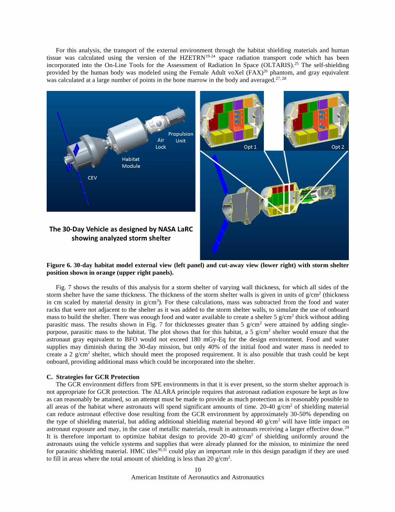
The 30-day habitat used for this analysis was comprised of a habitat module based on the ISS Multi-Purpose
Logistics Module (MPLM), an air-lock, a propulsion unit, and the Orion capsule with its service module, as shown
in Fig. 6. The habitat was outfitted with the vehicle systems and supplies needed for a 30-day mission using a master
equipment list developed for the DSG. The interior layout is a hypothetical layout of systems and not meant to
represent a baseline configuration of the DSG. Fig. 6 shows the location of the storm shelter in the central corridor
surrounded by the third row of racks. The protection provided by the shelter was examined for two astronaut
positions. In Option 1, the radiation exposure was evaluated for a 50th percentile female astronaut with her back to
the port rack and three 50th percentile male astronauts standing in front of her. In Option 2, the female astronaut for
which the analysis was performed was moved to the second position, as shown in Fig. 6, with one of her fellow
astronauts behind her and two others in front of her. Only the results for Option 2 are presented, because this
position provided a higher dose.
American Institute of Aeronautics and Astronautics
10
For this analysis, the transport of the external environment through the habitat shielding materials and human
tissue was calculated using the version of the HZETRN19-24 space radiation transport code which has been
incorporated into the On-Line Tools for the Assessment of Radiation In Space (OLTARIS).25 The self-shielding
provided by the human body was modeled using the Female Adult voXel (FAX)26 phantom, and gray equivalent
was calculated at a large number of points in the bone marrow in the body and averaged.27, 28
Figure 6. 30-day habitat model external view (left panel) and cut-away view (lower right) with storm shelter
position shown in orange (upper right panels).
Fig. 7 shows the results of this analysis for a storm shelter of varying wall thickness, for which all sides of the
storm shelter have the same thickness. The thickness of the storm shelter walls is given in units of g/cm2 (thickness
in cm scaled by material density in g/cm3). For these calculations, mass was subtracted from the food and water
racks that were not adjacent to the shelter as it was added to the storm shelter walls, to simulate the use of onboard
mass to build the shelter. There was enough food and water available to create a shelter 5 g/cm2 thick without adding
parasitic mass. The results shown in Fig. 7 for thicknesses greater than 5 g/cm2 were attained by adding single-
purpose, parasitic mass to the habitat. The plot shows that for this habitat, a 5 g/cm2 shelter would ensure that the
astronaut gray equivalent to BFO would not exceed 180 mGy-Eq for the design environment. Food and water
supplies may diminish during the 30-day mission, but only 40% of the initial food and water mass is needed to
create a 2 g/cm2 shelter, which should meet the proposed requirement. It is also possible that trash could be kept
onboard, providing additional mass which could be incorporated into the shelter.
C. Strategies for GCR Protection
The GCR environment differs from SPE environments in that it is ever present, so the storm shelter approach is
not appropriate for GCR protection. The ALARA principle requires that astronaut radiation exposure be kept as low
as can reasonably be attained, so an attempt must be made to provide as much protection as is reasonably possible to
all areas of the habitat where astronauts will spend significant amounts of time. 20-40 g/cm2 of shielding material
can reduce astronaut effective dose resulting from the GCR environment by approximately 30-50% depending on
the type of shielding material, but adding additional shielding material beyond 40 g/cm2 will have little impact on
astronaut exposure and may, in the case of metallic materials, result in astronauts receiving a larger effective dose.29
It is therefore important to optimize habitat design to provide 20-40 g/cm2 of shielding uniformly around the
astronauts using the vehicle systems and supplies that were already planned for the mission, to minimize the need
for parasitic shielding material. HMC tiles30,31 could play an important role in this design paradigm if they are used
to fill in areas where the total amount of shielding is less than 20 g/cm2.

American Institute of Aeronautics and Astronautics
11
Figure 7. Results of astronaut exposure analysis for an astronaut in a storm shelter in a deep space habitat
designed for 30-day missions.
GCR exposure incurred during a short duration stay on a Gateway habitat would provide minimal risk to
astronauts, but the risk of cancer induction correlates with cumulative radiation exposure. If the Gateway stay is only
one part of a larger mission, perhaps a launching point from which to begin a longer deep space mission, or if the
astronaut has or will participate in additional missions, it would be important to reduce that astronaut’s radiation
exposure as much as possible during each leg of each mission. It is, therefore, important to incorporate an ALARA
approach into the design of the entire habitat from the beginning.
V. Equivalent System Mass Analysis
Equivalent system mass (ESM)4 is an analytical technique that converts mass, volume, power, cooling, and crew
time resources all into equivalent mass that must be launched. The formula for ESM [kg] is given in Eq. (1).
ESM = M + (V*Veq) + (P*Peq) + (C*Ceq) + (CT*D*CTeq) (1)
M = the total mass of the system, including any resupplied items [kg],
V = the total pressurized volume of system [m3],
Veq = the mass equivalency factor for the pressurized volume infrastructure [kg/m3],
P = the total power requirement of the system [kWe],
Peq = the mass equivalency factor for the power generation infrastructure [kg/kWe],
C = the total cooling requirement of the system [kWth],
Ceq = the mass equivalency factor for the cooling infrastructure [kg/kWth],
CT = the total crew time requirement to operate and maintain the system per year [CM-hrs/yr],
D = the duration of the mission segment of interest [yr],
CTeq = the mass equivalency factor for the crew time support [kg/CM-hr].
The system to be studied with ESM can be an entire spacecraft or one particular subsystem. In this study,
difference or “delta” ESM was calculated from a selected reference case for five different trash disposal systems.

American Institute of Aeronautics and Astronautics
12
Thus, Eq. (1), in difference format (DESM), was used to sum up all the differences in mass and resource needs for
the five options relative to the reference case. The ESM mass equivalency factors, also known as “infrastructure cost
factors”, that were used in this trade study are listed in Table 4. Volume and power factors were derived specifically
from the current DSG and recent Evolvable Mars Campaign MTV designs, whereas the cooling and crew time
factors were taken from Ref. 32, since this information was not available for DSG or MTV.
Table 4. ESM mass equivalency factors for DSG and MTV
Equivalency factors: Gateway Mars
Volume (kg/m3) 35.9 29.5
Power (kg/kW) 60.0 41.0
Cooling (kg/kW) 55.4 55.4
Crew time (kg/CM-hr) 0.8 0.8
The components of mass difference (DM) are given in Eq. (2). The first three are combined into “D mass of
equipped module(s)” in the results tables in section VI. Resource differences for volume, power, cooling and crew
time were also computed for each case and shown in the results tables. For volume, both the volume occupied by the
trash processing equipment and the trash itself were considered. The later was accounted for by computing the
difference in net habitable volume (NHV) for the different cases at the midpoint of the mission. NHV is the room
left for astronauts to move about the spacecraft after it is fully loaded, and thus is important for work efficiency and
crew morale. The midpoint for the DSG reference case (D) was considered to be the beginning of EM-5, starting
with 30 days of trash remaining on board from EM-4 and needing to accommodate another 30 days of trash from
EM-5. In that reference case, all 60 days of trash would be stored on DSG for another year before it can be removed
by the departing logistics module. For the MTV mission, the midpoint was considered to be half way to Mars. As
time goes by and supplies are consumed, there will be more room on board (more in some cases than others). Thus,
the trip to Mars will be a worse case than the return trip from a NHV perspective.
DM = DMmodules + DMequip + DMconsumables + DMprop + DMcredit (2)
DMmodules = difference in mass of the habitation and logistics modules [kg],
DMequip = difference in mass of equipment associated with the trash disposal system [kg] (e.g. HMC),
DMconsumables = difference in mass of consumables due to trash disposal [kg] (e.g. trash-lock air loss),
DMprop = difference in propulsion system mass due to trash disposal strategy [kg],
DMcredit = difference in launch mass due to trash recycling [kg] (e.g. water recovery from TtG).
As mentioned above, DESM was computed for each case studied, relative to a reference case. For DSG the
reference case was considered to be D (Storage/logistics module) because that is the longest duration trash storage
option being evaluated by the DSG study team. For MTV the reference case was considered to be C (Trash-to-gas)
because that was the assumption used in the Evolvable Mars Campaign analysis.
VI. Results
A. Deep Space Gateway
A description of the DSG mission was provided in section IIA and details of the trash disposal options were
covered in section III. Results of the ESM analysis described in section V are shown in Table 5 for the early
missions of DSG. The period covered by this analysis was EM-4 through EM-6 with assumed trash generation of 30
days each on EM-4 and EM-5 and storage of up to 2 years total in the reference case (D). The fact that all DESM
totals besides case D are positive indicates that they are all expected to require greater launch mass than the
reference case. Case E (HMC) is the closest to D, with minor mass increases for the HMC device and its power and
cooling requirements. HMC received credits for water recovery from trash and volume recovered by compaction,
but not for producing radiation shielding tiles. While these tiles could help reduce crew radiation exposure, a credit
was not given based on the radiation analysis results described in section IV.
Case C (TtG) and case B (Trash-lock) are both realistic disposal scenarios but show modest increases in launch
mass relative to reference case D. If TtG power could be reduced and if trash-lock mass penalty could be reduced by

American Institute of Aeronautics and Astronautics
13
doing double duty with a small airlock used for other purposes, then these technologies would trade more favorably.
Case A did not trade well here because an extra full-sized logistics module was assumed to dispose of trash;
however, if multiple smaller resupply logistics modules can be used, or if there are other factors driving inclusion of
additional logistics modules, then case A may trade better. Another reason to include one or more of the alternative
trash disposal strategies or technologies on DSG may be to prove them out for future Mars missions.
Differences in the propulsion system mass were considered negligible for all cases based on the data in Table 2,
which indicated that total annual station keeping propellant is small. Thus, savings due to lightening the spacecraft
by trash disposal would be even less. Though not calculated here, a TtG system addition to DSG that could produce
cold gases for a resistojet or even propellants, could reduce the need for SEP propellants and potentially change
these trade study results over time. None of the ESM differences due to crew time were very significant based on the
crew time equivalency used. This factor could become more important to mission planners depending on mission
objectives and level of automation in the DSG.
In Table 5 “D mass of equipped module(s)” includes the differences in mass for logistics modules, trash
processing equipment, spare parts and logistics. Most notable is the extra logistics module assumed in case A, which
could probably be reduced in mass somewhat, depending on the size of the logistics module or trash pod to be sent
to DSG. It is assumed that long term trash storage technologies (barrier materials, odor absorption, and minimal
processing) can be developed to support option D, which had an estimated mass penalty of 13 kg more than regular
trash bags in this study. Another difference in logistics mass was the gas loss from the trash-lock in case B, which
amounted to 3 kg. “Resource credits” come from water recovery from trash in cases C and E. While these early
DSG missions alone cannot justify this added complexity, the benefit over the life of DSG may. Also shown in
Table 5 are the volume differences due to the different types of trash processing equipment and due to NHV, as
described in section V. Similarly, the power, cooling and crew time contributions to ESM differences are shown for
each case. Peak power is used since the maximum device power could drive the size of the spacecraft solar arrays;
however, since trash processing can be scheduled, some reduction may be possible.
Table 5. Results for Gateway trash strategies showing difference in equivalent system mass versus case D
for two 30-day visits. Case Trash strategy D mass of
equipped
module(s)
(kg)
D mass of
propulsion
system
(kg)
D mass
resource
credit
(kg)
Trash
equip.
vol.
(m3)
D volume
of trash
equip.
(m3)
D
NHV
(m3)
D ESM
for vol.
(kg)
D power
of trash
equip.
(kW)
D ESM
for
power
(kg)
D ESM
for
cooling
(kg)
Total
trash
ops. crew
time (hr)
D crew
time for
trash ops.
(hr)
D ESM
for crew
time
(kg)
Total
DESM
(kg)
A Extra log module 4,125 ~0 0 0.01 -0.01 -1.10 -40 0.000 0 0 5 1 1 4086
B Trash-lock 499 ~0 0 0.50 0.48 -1.10 -22 0.020 1 1 2 -2 -2 478
C Trash-to-gas 175 ~0 -31 0.14 0.12 -1.10 -35 2.000 120 111 6 2 2 341
D Storage/Log module 0 ~0 0 0.02 0.00 0.00 0 0.000 0 0 4 0 0 0
E HMC 148 ~0 -38 0.20 0.18 -0.80 -22 0.500 30 28 12 8 6 152
B. Mars Transit
A description of the MTV mission was provided in Ref. 2 along with details of the trash disposal options for that
mission. Updated results are presented here for the Hybrid transportation architecture. Table 6 shows the major
components of ESM and the total difference in ESM for each case relative to reference case C (Trash-to-gas). As in
the previous study, case A shows the lowest launch mass, followed by cases C, B, E and D. However, with all the
ESM factors considered, some of the differences were not as great as before. For example, case A was only 232 kg
less than C, which is only 0.2% of the MTV total launch mass. Most of the case A advantage is due to propellant
savings that come from being able to drop the logistics module mass plus its waste contents prior to the Earth return
burns. In the opposite direction, most of the large case D disadvantage comes from the extra propellant required to
push around the stored trash. Cases B, C and E are all somewhat competitive, with different attributes. Case B
suffers from the structural mass of the trash-lock and case E from the fact that HMC tile mass is kept on board for
radiation protection. A quantitative benefit for improved radiation protection was not assigned to case E, even
though it was significant, since the analysis in Ref. 2 showed that minimum SPE shielding requirements could be
met without the tiles. Case C, a close second based on total ESM, could benefit most from reduced power or other
tangible benefits such as propellant production. The potential benefit of producing cold gases for resistojets, or even
propellants, was not included in this study.
In Table 6 “D mass of equipped module(s)” includes the differences in mass for both habitation and logistics
modules, trash processing equipment, spare parts and logistics. Differences in logistics include extra propellant for
logistics module disposal in case A, gas loss from the trash-lock in case B and extra odor containment in case D.

American Institute of Aeronautics and Astronautics
14
“Resource credits” come from water recovery from trash in cases C and E. Table 6 also shows volume, power,
cooling and crew time contributions to ESM differences for each case.
Table 6. Results for Mars transit trash strategies showing difference in equivalent system mass versus case
C. Case Trash
strategy
D mass of
equipped
module(s)
(kg)
D mass
of prop.
sys. (kg)
Resource
credit
(kg)
D mass
resource
credit
(kg)
Trash
equip.
vol.
(m3)
D vol.
of trash
equip.
(m3)
D NHV
(m3)
D ESM
for
volume
(kg)
Trash
equip. peak
power (kW)
Dpower
of trash
equip
(kW)
D ESM
for
power
(kg)
D ESM
for
cooling
(kg)
Total
trash
ops.
time (hr)
D crew
time for
trash ops.
(hr)
D ESM
for crew
time
(kg)
Total
DESM
(kg)
A Log module 1,113 -1,730 0 314 0.069 -0.067 10.13 296 0.000 -2.000 -82 -111 25 -41 -33 -232
B Trash-lock 349 800 0 314 0.500 0.363 -1.06 -21 0.020 -1.980 -81 -110 27 -39 -31 1220
C Trash-to-gas 0 0 -314 0 0.137 0.000 0.00 0 2.000 0.000 0 0 66 0 0 0
D Storage 24 6,810 0 314 0.267 0.130 3.55 108 0.000 -2.000 -82 -111 20 -46 -37 7027
E HMC -26 2,550 -390 -77 0.200 0.063 0.85 27 0.500 -1.500 -62 -83 127 61 49 2378
VII. Conclusions & Recommendations
With the information available today, a detailed ESM analysis for DSG has shown that the Storage/logistics
module trash strategy leads to the lowest launch mass. A similar ESM analysis for MTV has shown that the
Logistics module strategy leads to the lowest launch mass when compared one at a time to four other options. Given
the fact that several options were competitive and that combinations of the strategies have not yet been considered, it
is recommended that all but the MTV Storage case continue to be developed and analyzed. The DSG Extra logistics
module case should be optimized and analyzed to understand the secondary benefits of being able to offload trash
between each crewed visit compared to the launch costs. Development of trash containers that can sufficiently
contain wastes and suppress smell for two years should be proven for the DSG. Besides analyzing the combination
of Logistic module and TtG for MTV, TtG should be further assessed for its risks and rewards, which could include
resistojet propellant production. The value that HMC radiation tiles provide toward NASA’s ALARA radiation
protection principles should be further refined and quantified for both the DSG and MTV as more detailed vehicle
models are developed.
Interestingly, the ESM drivers for the two missions studied were completely different. For the MTV, propulsion
system consideration and how much mass could be jettisoned during the mission dominated the results. For the
DSG, which has much more modest propulsion requirements, the mass and power of the trash processing equipment
became the most important ESM factors.
Another future refinement to this study could include assessing the disposal of feces and urine brine in addition
to trash. Most of these trash strategies should be able to accommodate those wastes as well, resulting in additional
mission benefits. However, the operational ability to transfer the collected fecal waste, and details of urine brine
processing must be assessed before these can be considered fully feasible. Finally, additional stakeholders such as
crew, medical, operations and human factors representatives should be consulted to speak for the pros and cons of
the leading trash disposal strategies that are difficult to quantify in an ESM analysis.
Appendix
The complete set of proposed SPE protection requirements for Gateway habitats with the related rationale
follows:
1. The habitat shall provide protection to ensure that gray equivalent to astronaut blood forming organs
(BFO) does not exceed 250 mGy-Eq. for the design SPE.
Rationale: Radiation sources in free space, beyond low Earth orbit, include Galactic Cosmic Rays (GCRs)
and Solar Particle Events (SPEs). This radiation design requirement is intended to limit astronaut exposure
to SPEs and does not address GCR exposure or previous mission exposures. SPEs are intermittent events
lasting a few hours to a few days, during which an elevated number of charged particles, primarily
protons, emanating from the sun may impinge on the spacecraft. This requirement is imposed to prevent
clinically significant non-cancer tissue effects, such as performance degradation, sickness, or death during
the mission, resulting from SPEs. Short duration and career Permissible Exposure Limits (PELs), which
can be found in NASA Standard 3001, Volume 1, have been established for astronaut space flight radiation
exposure for lens, skin, BFO, circulatory system, and central nervous system to prevent non-cancer effects.
Of these PELs, the requirement that gray equivalent to BFO not exceed 250 mGy-Eq during any 30 day

American Institute of Aeronautics and Astronautics
15
period is expected to drive shielding design; a shield design which ensures that this exposure limit has not
been exceeded will also ensure that the other PELs for non-cancer tissue effects have not been exceeded.
Gray equivalent is calculated by weighting the particle flux impinging on the body with Relative Biological
Effectiveness (RBE) values which take into account the varying ability of different types of particles to
cause non-cancer effects. In accordance with NASA Standard 3001, Volume 1, the RBEs recommended by
the National Council on Radiation Protection and Measurements in 2000 (NCRP 132) shall be used for
this calculation.
2. The proton energy spectrum given in Table 7 shall be used as the design reference SPE environment.
Table 7. Energy spectrum for the design reference SPE environment.
Energy
(MeV)
Proton Fluence
(#/cm2-MeV)
Energy
(MeV)
Proton Fluence
(#/cm2-MeV)
Energy
(MeV)
Proton Fluence
(#/cm2-MeV)
Energy
(MeV)
Proton Fluence
(#/cm2-MeV)
Energy
(MeV)
Proton Fluence
(#/cm2-MeV)
1.000E-02 7.761E+14 5.770E-01 3.651E+11 4.810E+00 9.004E+09 3.426E+01 1.641E+08 2.484E+02 5.714E+05
1.338E-02 4.329E+14 6.480E-01 2.979E+11 5.317E+00 7.510E+09 3.775E+01 1.298E+08 2.756E+02 4.006E+05
1.790E-02 2.424E+14 7.263E-01 2.442E+11 5.875E+00 6.257E+09 4.160E+01 1.022E+08 3.060E+02 2.773E+05
2.391E-02 1.369E+14 8.129E-01 2.008E+11 6.490E+00 5.208E+09 4.584E+01 8.008E+07 3.407E+02 1.862E+05
3.183E-02 7.805E+13 9.086E-01 1.655E+11 7.168E+00 4.330E+09 5.052E+01 6.136E+07 3.794E+02 1.230E+05
4.210E-02 4.531E+13 1.014E+00 1.368E+11 7.914E+00 3.594E+09 5.568E+01 4.700E+07 4.232E+02 8.060E+04
5.511E-02 2.697E+13 1.130E+00 1.135E+11 8.736E+00 2.979E+09 6.137E+01 3.600E+07 4.728E+02 5.236E+04
7.112E-02 1.657E+13 1.258E+00 9.421E+10 9.641E+00 2.465E+09 6.765E+01 2.754E+07 5.291E+02 3.367E+04
9.027E-02 1.055E+13 1.400E+00 7.839E+10 1.064E+01 2.035E+09 7.460E+01 2.103E+07 5.930E+02 2.141E+04
1.125E-01 6.989E+12 1.556E+00 6.527E+10 1.174E+01 1.677E+09 8.226E+01 1.603E+07 6.665E+02 1.337E+04
1.375E-01 4.810E+12 1.729E+00 5.441E+10 1.294E+01 1.379E+09 9.074E+01 1.219E+07 7.505E+02 8.141E+03
1.657E-01 3.411E+12 1.919E+00 4.541E+10 1.427E+01 1.131E+09 1.001E+02 9.237E+06 8.471E+02 4.859E+03
1.968E-01 2.489E+12 2.129E+00 3.792E+10 1.574E+01 9.248E+08 1.105E+02 6.966E+06 9.588E+02 2.856E+03
2.303E-01 1.872E+12 2.361E+00 3.168E+10 1.735E+01 7.542E+08 1.220E+02 5.234E+06 1.091E+03 1.633E+03
2.675E-01 1.428E+12 2.617E+00 2.647E+10 1.913E+01 6.132E+08 1.348E+02 3.908E+06 1.244E+03 9.199E+02
3.082E-01 1.108E+12 2.900E+00 2.213E+10 2.108E+01 4.969E+08 1.490E+02 2.902E+06 1.418E+03 5.152E+02
3.525E-01 8.711E+11 3.211E+00 1.850E+10 2.323E+01 4.013E+08 1.648E+02 2.134E+06 1.625E+03 2.802E+02
4.010E-01 6.929E+11 3.555E+00 1.546E+10 2.561E+01 3.229E+08 1.824E+02 1.560E+06 1.869E+03 1.486E+02
4.542E-01 5.560E+11 3.933E+00 1.292E+10 2.822E+01 2.588E+08 2.018E+02 1.131E+06 2.158E+03 7.696E+01
5.126E-01 4.493E+11 4.350E+00 1.079E+10 3.109E+01 2.065E+08 2.239E+02 8.074E+05 2.500E+03 3.891E+01
Rationale: This spectrum is equivalent to the sum of the proton spectra for the events which occurred
during October 1989, as modeled by Alan Tylka.12 The combined proton fluence for the events that
occurred on October 19, 22, and 24, 1989 represent the most intense SPE environment occurring during a
30 day period during the era of satellite measurements. Astronaut exposure behind thick shields will be
dominated by the more penetrating high energy particles and these events included a large number of high
energy protons. The Tylka models for the individual events are based on satellite measurements and Earth
surface neutron measurements, to ensure that the high energy component of the events are accurately
represented. The combined environment is approximately equivalent to a 90 percentile event for a one-year
mission, for energies relevant to human exposure inside spacecraft, using the Xapsos model for Emission of
Solar Protons (ESP).
3. If the protection system requires assembly and installation, it must take no more than 30 minutes.
Rationale: Protection systems may take the form of a designated location, or storm shelter, within the
habitat providing superior shielding in which the astronauts will stay during the period of elevated
radiation. This storm shelter may be a permanent structure or it could require assembly, during which
mass is moved from other locations within the habitat to create the shelter. Protections systems could also
take the form of wearable garments or blankets. If time is needed to assemble a shelter and/or don a
protection garment, it must take no more than 30 minutes. The rise time and total duration has varied for
historic events. It is possible that SPE radiation exposure incurred before astronauts enter the shelter will
result in their exceeding 250 mGy-eq to BFO, but if assembly time is no more than 30 minutes, the
probability of this occurring is expected to be low. It should be noted that if onboard supplies,
consumables, and/or equipment are used in the construction of the storm shelter, a method of tracking the

American Institute of Aeronautics and Astronautics
16
necessary items throughout the mission duration that ensures that an adequate quantity exists and
assembly can be completed in no more than 30 minutes would be needed. Similarly, the length of time
astronauts will need to spend in the shelter could be as short as a few hours or as long as a few days.
Access to food, supplies, and vehicle systems should not be limited by storm shelter design. This could take
the form of inclusion of at least a few day’s food and the ability to communicate with vehicle systems in the
shelter or an ability to egress and ingress quickly, to allow astronauts to leave the shelter when necessary.
4. Spacecraft protection systems shall be designed to ensure that astronaut radiation exposure is kept As
Low As Reasonably Achievable (ALARA).
Rationale: Included in the Permissible Exposure Limits in NASA Standard 3001, Volume 1 is the
requirement that in-flight radiation exposure be maintained using the ALARA principle. For space habitat
design, ALARA is an iterative process of integrating radiation protection into the design process, ensuring
optimization of the design to afford the most protection possible, within other constraints of the vehicle
systems. The protection from radiation exposure is ALARA when the expenditure of further resources
would be unwarranted by the reduction in exposure that would be achieved. Following ALARA minimizes
the risk of cancer induction and other stochastic effects, for which there is no threshold dose.
Acknowledgments
The authors would like to thank Molly Anderson (NASA Johnson Space Center) for her technical review and
Matt Simon (NASA Langley Research Center) for his habitation analyses insight. The authors would also like to
thank Chel Stromgren (Binera, Inc.) and Felipe Escobar (Binera, Inc.) for their expertise in estimating logistics,
Ryan Joyce (NASA Langley Research Center) for collecting the delta-velocity and estimated propellant
requirements for cislunar orbits, and Patrick Chai (NASA Langley Research Center) for estimating logistics module
disposal needs at Mars. Finally, the authors would like to thank H. Lee Abston, Charles J. Wittkop, and Nicholos A.
Vitullo (NASA Langley Research Center) for creating and ray-tracing the 30-day habitat model.
References
1 Linne, et al., “Waste Management Options for Long-Duration Space Missions: When to Reject, Reuse, or Recycle,”
AIAA 2014-0497.
2 Ewert, et al., “Comparing Trash Disposal to Use as Radiation Shielding for a Mars Transit Vehicle”, 47th International
Conference on Environmental Systems, ICES-2017-178.
3 National Aeronautics and Space Administration Advisory Council March 30 - 31, 2017 Public Meeting,
https://www.nasa.gov/sites/default/files/atoms/files/heo_update_tagged.pdf
4 Levri, J.A., et al., “Advanced Life Support Equivalent System Mass Guidelines Document”, NASA/TM-2003-212278,
http://ntrs.nasa.gov/archive/nasa/casi.ntrs.nasa.gov/20040021355.pdf
5 Anthony, S. M., Hintze, P. E., Allada, R. (2014) “Trash-to-Gas: Determining the Ideal Technology for Converting Space
Trash into Useful Products,” 44th International Conference on Environmental Systems, American Institute of Aeronautics and
Astronautics.
6 NASA Space Flight Human-System Standard, Volume 1, Revision A: Crew Health, NASA-STD-3001, Volume 1,
Revision A w/ Change 1, 2015.
7 Operational Radiation Safety Program for Astronauts in Low-Earth Orbit: A Basic Framework. NCRP Report No. 142,
2002.
8 Wilson, J.W., Kim, M.H., De Angelis, G., Cucinotta, F.A., Yoshizawa, N., and Badavi, F.F., “Implementation of Gy-Eq
for Deterministic Effects Limitation in Shield Design,” J. Radiat. Res., 43: SUPPL., S103-S106, 2002.
9 NASA Space Flight Human-System Standard, Volume 2, Revision A: Human Factors, Habitability, and Environmental
Health, NASA-STD-3001, Volume 2, Revision A, 2015.
10 Orion Multi Purpose Crew Vehicle (MPCV) Program: Human-Systems Integration Requirements, NASA MPCV 70024,
Revision C, 2016.
11 Cross-Program Design Specification for Natural Environments (DSNE), NASA SLS-SPEC-159, Revision C, 2015.
12 Atwell, W., Tylka, A., Deitrich, W., Badavi, F.F., and Rojdev, K., “Spectral Analyses and Radiation Exposures from
Ground-Level Enhancement (GLE) Solar Proton Events: A Comparison of Methodologies,” 41st International Conference on
Environmental Systems (ICES), AIAA 2011-5253, 2011.
13 Cerro, J.A., “Trade Study of System Level Ranked Radiation Protection Concepts for Deep Space Exploration,” 72nd
Annual SAWE Conference, SAWE Paper No. 3593, St. Louis, MO, 2013.

American Institute of Aeronautics and Astronautics
17
14 Simon, M.A., Clowdsley, M.S., and Walker, S.A., “Habitat Design Considerations for Implementing Solar Particle Event
Radiation Protection,” 43rd International Conference on Environmental Systems (ICES), AIAA 2103-3403, Vail, CO, 2013.
15 Walker, S.A., Clowdsley, M.S., Abston, H.L., Simon, M.A., and Gallegos, A.M., “Radiation Exposure Analysis
Supporting the Development of Solar Particle Event Shielding Technologies,” 43rd International Conference on Environmental
Systems (ICES), AIAA 2103-3402, Vail, CO, 2013.
16 Simon, M.A., Cerro, J.A., and Clowdsley, M.S., “RadWorks Storm Shelter Design for Solar Particle Event Shielding,”
2013 AIAA Space Conference & Exposition, AIAA 2013-5435, San Diego, CA, 2013.
17 Simon, M.A., Cerro, J.A., Latorella, K.A., Clowdsley, M.S., Watson, J.J., Albertson, C., Norman, R.B., and Le Boffe,
V.M., “Design of Two RadWorks Storm Shelters for Solar Particle Event Shielding,” 2014 AIAA Space Conference &
Exposition, AIAA 2014-4473, San Diego, CA, 2014.
18 Cerro, J.A., Latorella, K.A., Simon, M.A., Watson, J.J., Albertson, C., and Le Boffe, V.M., “Development of Logistics
for Building Radiation Storm Shelters and their Operational Evaluation,” 2015 AIAA Space Conference & Exposition, AIAA
2015-4402, Pasedena, CA, 2015.
19 Wilson, J.W., Townsend, L.W., Schimmerling, W., Khandelwal, G.S., Khan, F., Nealy, J.E., Cucinotta, F.A., Simonsen,
L.C., Shinn, J.L., and Norbury, J.W., “Transport Methods and Interactions for Space Radiations.” NASA Reference Publication
1257, 1991.
20 Wilson, J.W., Badavi, F.F., Cucinotta, F.A., Shinn, J.L., Badhwar, G.D., Silberberg, R., Tsao, C.H., Townsend, L.W.,
and Tripathi, R.K., “HZETRN: Description of a Free-Space Ion and Nucleon Transport and Shielding Computer Program,”
NASA TP-3495, 1995.
21 Slaba, T.C, Blattnig, S.R., Clowdsley, M.S., Walker, S.A., Badavi, F.F., An improved neutron transport algorithm for
HZETRN, Adv. Space Res. 46, 800-810, 2010.
22 Slaba, T.C., Blattnig, S.R., Badavi, F.F., Faster and more accurate transport procedures for HZETRN. J. Comput. Phys.
229, 9397–9417, 2010.
23 Slaba, T.C., Faster Heavy Ion Transport for HZETRN. NASA Technical Paper 2013-217803, 2013.
24 Slaba, T.C. Blattnig, S.R., Tweed, J., Reduced discretization error in HZETRN. J. Comput. Phys. 234, 217-229, 2013.
25 Singleterry, R. C., et al., “OLTARIS: On-Line Tool for the Assessment of Radiation in Space,” Acta Astronautica, Vol.
68, 2011, pp. 1086-1097.
26 Kramer, R., et al., “All about FAX: A Female Adult Voxel Phantom for Monte Carlo Calculations in Radiation
Protection Dosimetry,” Physics in Medicine and Biology, Vol. 49, 2004, pp. 5203-5216.
27 Slaba, T.C., Qualls, G.D., Clowdsley, M.S., Blattnig, S.R., Walker, S.A., and Simonsen, L.C., “Utilization of CAM,
CAF, MAX, and FAX for Space Radiation Analysis Using HZETRN,” Adv. Space Res., 45, 866-883, 2010.
28 Slaba, T.C., Qualls, G.D., Clowdsley, M.S., Blattnig, S.A., Simonsen, L.C., S.R., Walker, and Singleterry, R.C.,
“Analysis of Mass Averaged Tissue Doses in CAM, CAF, MAX, and FAX,” NASA TP-2009-215562, 2009.
29 Slaba, T.C., Bahadori, A.A., Reddell, B.D., Singleterry, R.C., Clowdsley, M.S., and Blattnig, S.R., “Optimal Shielding
Thickness for Galactic Cosmic Ray Environments,” Life Sciences in Space Res., Vol. 12, 1-15.
30 Turner, M.F., Fisher, J.W., Broyan, J.L. and Pace, G., “Generation 2 Heat Melt Compactor Development,” paper #ICES-
2014-024, 44th International Conference on Environmental Systems ICES, 13-17 July 2014.
31 Bahadori, A., et al., “Measuring space radiation shielding effectiveness”, Paris, International Conference on Radiation
Shielding 2016.
32 NASA. “Advanced Life Support Baseline Values and Assumptions Document (BVAD).” NASA/ TP-2015-218570.
National Aeronautics and Space Administration, Lyndon B. Johnson Space Center, Houston, TX. 2015.