Embed Size (px)
Citation preview
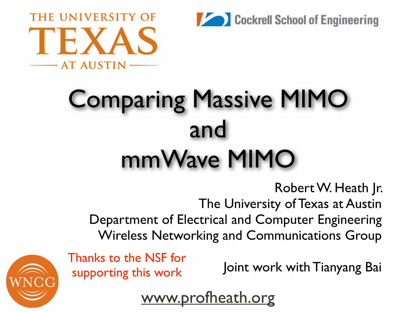
Comparing Massive MIMO and
mmWave MIMORobert W. Heath Jr.
The University of Texas at Austin Department of Electrical and Computer Engineering
Wireless Networking and Communications Group !
Joint work with Tianyang Bai
www.profheath.org
Thanks to the NSF for supporting this work
(c) Robert W. Heath Jr. 2014
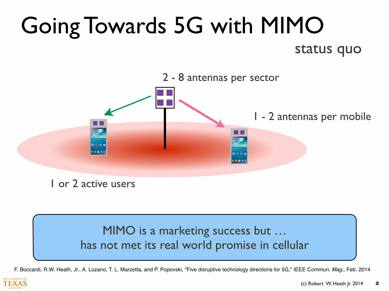
Going Towards 5G with MIMO
2
2 - 8 antennas per sector
1 - 2 antennas per mobile
1 or 2 active users
MIMO is a marketing success but … has not met its real world promise in cellular
status quo
F. Boccardi, R.W. Heath, Jr., A. Lozano, T. L. Marzetta, and P. Popovski, "Five disruptive technology directions for 5G," IEEE Commun. Mag., Feb. 2014

(c) Robert W. Heath Jr. 2014
Going Towards 5G with MIMO
3
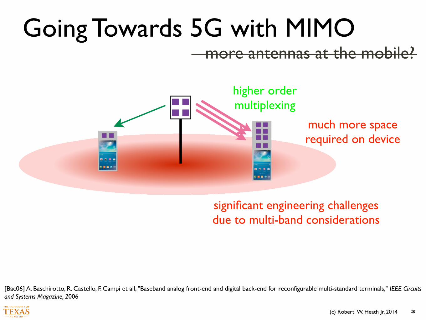
higher order multiplexing
more antennas at the mobile?
much more space required on device
significant engineering challenges due to multi-band considerations
[Bac06] A. Baschirotto, R. Castello, F. Campi et all, "Baseband analog front-end and digital back-end for reconfigurable multi-standard terminals," IEEE Circuits and Systems Magazine, 2006
(c) Robert W. Heath Jr. 2014
Going Towards 5G with MIMO
3
higher order multiplexing
more antennas at the mobile?
much more space required on device
significant engineering challenges due to multi-band considerations
[Bac06] A. Baschirotto, R. Castello, F. Campi et all, "Baseband analog front-end and digital back-end for reconfigurable multi-standard terminals," IEEE Circuits and Systems Magazine, 2006
(c) Robert W. Heath Jr. 2014
Going Towards 5G with MIMO
4
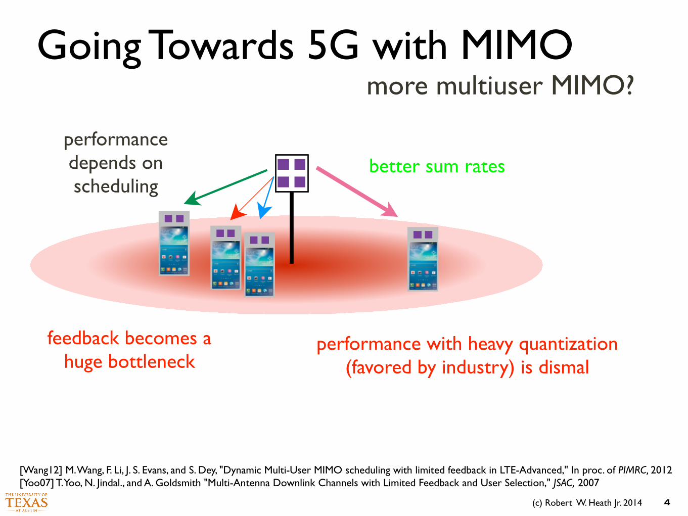
more multiuser MIMO?
better sum rates
feedback becomes a huge bottleneck
performance depends on scheduling
performance with heavy quantization (favored by industry) is dismal
[Wang12] M. Wang, F. Li, J. S. Evans, and S. Dey, "Dynamic Multi-User MIMO scheduling with limited feedback in LTE-Advanced," In proc. of PIMRC, 2012 [Yoo07] T. Yoo, N. Jindal., and A. Goldsmith "Multi-Antenna Downlink Channels with Limited Feedback and User Selection," JSAC, 2007

(c) Robert W. Heath Jr. 2014
Going Towards 5G with MIMO
4
more multiuser MIMO?
better sum rates
feedback becomes a huge bottleneck
performance depends on scheduling
performance with heavy quantization (favored by industry) is dismal
[Wang12] M. Wang, F. Li, J. S. Evans, and S. Dey, "Dynamic Multi-User MIMO scheduling with limited feedback in LTE-Advanced," In proc. of PIMRC, 2012 [Yoo07] T. Yoo, N. Jindal., and A. Goldsmith "Multi-Antenna Downlink Channels with Limited Feedback and User Selection," JSAC, 2007
(c) Robert W. Heath Jr. 2014
Going Towards 5G with MIMO
5
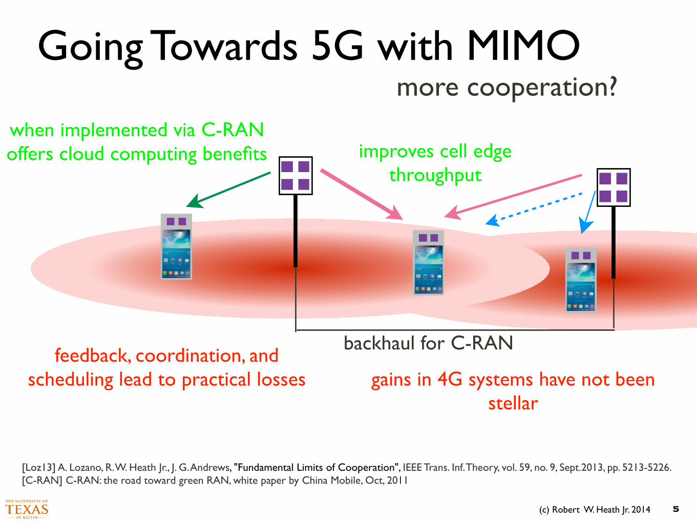
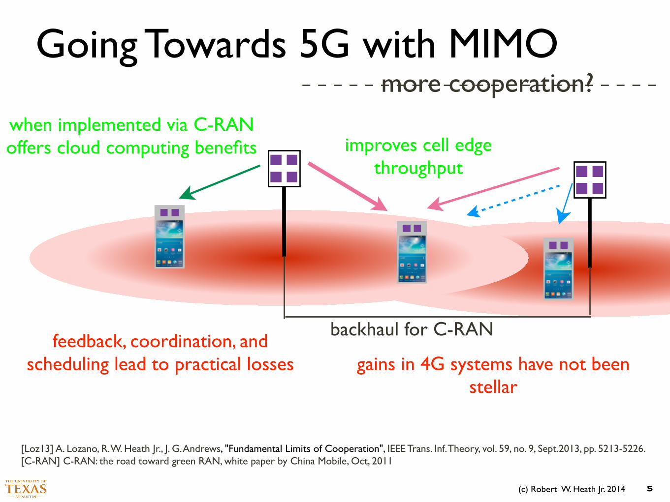
more cooperation?
improves cell edge throughput
feedback, coordination, and scheduling lead to practical losses
when implemented via C-RAN offers cloud computing benefits
gains in 4G systems have not been stellar
backhaul for C-RAN
[Loz13] A. Lozano, R. W. Heath Jr., J. G. Andrews, "Fundamental Limits of Cooperation", IEEE Trans. Inf. Theory, vol. 59, no. 9, Sept.2013, pp. 5213-5226. [C-RAN] C-RAN: the road toward green RAN, white paper by China Mobile, Oct, 2011
(c) Robert W. Heath Jr. 2014
Going Towards 5G with MIMO
5
more cooperation?
improves cell edge throughput
feedback, coordination, and scheduling lead to practical losses
when implemented via C-RAN offers cloud computing benefits
gains in 4G systems have not been stellar
backhaul for C-RAN
[Loz13] A. Lozano, R. W. Heath Jr., J. G. Andrews, "Fundamental Limits of Cooperation", IEEE Trans. Inf. Theory, vol. 59, no. 9, Sept.2013, pp. 5213-5226. [C-RAN] C-RAN: the road toward green RAN, white paper by China Mobile, Oct, 2011
(c) Robert W. Heath Jr. 2014
Going Towards 5G with MIMO
6
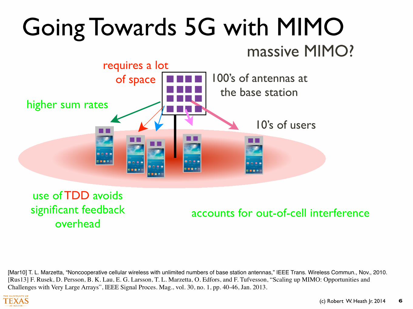
massive MIMO?
100’s of antennas at the base station
use of TDD avoids significant feedback
overhead
higher sum rates
accounts for out-of-cell interference
10’s of users
[Mar10] T. L. Marzetta, “Noncooperative cellular wireless with unlimited numbers of base station antennas,” IEEE Trans. Wireless Commun., Nov., 2010.![Rus13] F. Rusek, D. Persson, B. K. Lau, E. G. Larsson, T. L. Marzetta, O. Edfors, and F. Tufvesson, “Scaling up MIMO: Opportunities and Challenges with Very Large Arrays”, IEEE Signal Proces. Mag., vol. 30, no. 1, pp. 40-46, Jan. 2013.
requires a lot of space
(c) Robert W. Heath Jr. 2014
Going Towards 5G with MIMO
7
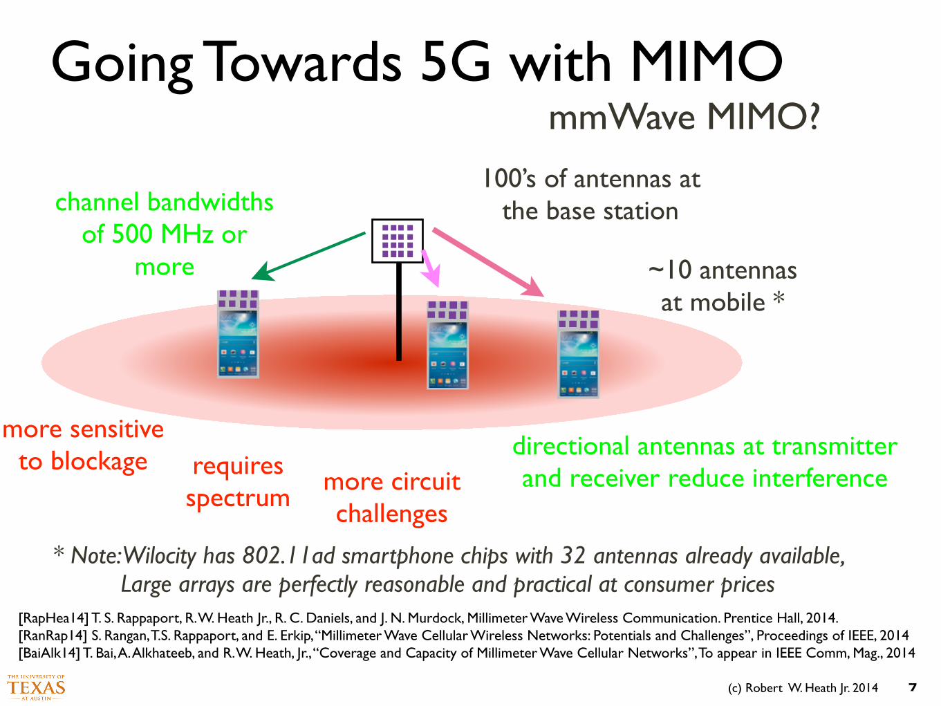
mmWave MIMO?
100’s of antennas at the base station
more sensitive to blockage
channel bandwidths of 500 MHz or
more
directional antennas at transmitter and receiver reduce interference
~10 antennas at mobile *
requires spectrum
[RapHea14] T. S. Rappaport, R. W. Heath Jr., R. C. Daniels, and J. N. Murdock, Millimeter Wave Wireless Communication. Prentice Hall, 2014. [RanRap14] S. Rangan, T.S. Rappaport, and E. Erkip, “Millimeter Wave Cellular Wireless Networks: Potentials and Challenges”, Proceedings of IEEE, 2014 [BaiAlk14] T. Bai, A. Alkhateeb, and R. W. Heath, Jr., “Coverage and Capacity of Millimeter Wave Cellular Networks”, To appear in IEEE Comm, Mag., 2014
more circuit challenges
* Note: Wilocity has 802.11ad smartphone chips with 32 antennas already available, Large arrays are perfectly reasonable and practical at consumer prices
(c) Robert W. Heath Jr. 2014 8
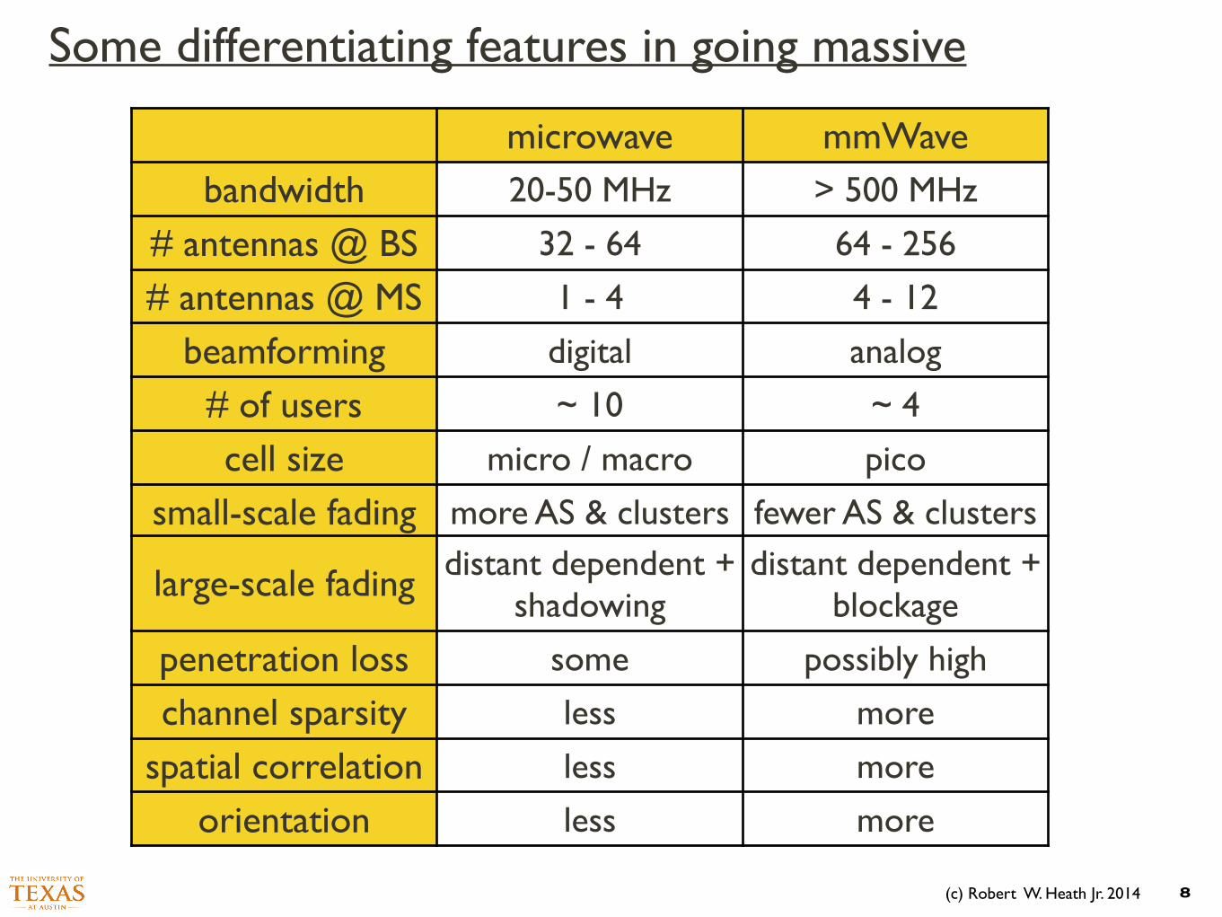
microwave mmWavebandwidth 20-50 MHz > 500 MHz
# antennas @ BS 32 - 64 64 - 256
# antennas @ MS 1 - 4 4 - 12
beamforming digital analog
# of users ~ 10 ~ 4
cell size micro / macro pico
small-scale fading more AS & clusters fewer AS & clusters
large-scale fading distant dependent + shadowing
distant dependent + blockage
penetration loss some possibly high
channel sparsity less more
spatial correlation less more
orientation less more
Some differentiating features in going massive
(c) Robert W. Heath Jr. 2014
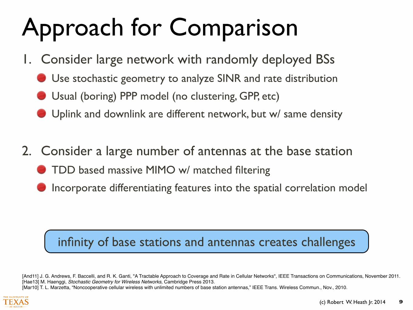
Approach for Comparison
9
infinity of base stations and antennas creates challenges
1. Consider large network with randomly deployed BSs Use stochastic geometry to analyze SINR and rate distribution
Usual (boring) PPP model (no clustering, GPP, etc)
Uplink and downlink are different network, but w/ same density
!
2. Consider a large number of antennas at the base station TDD based massive MIMO w/ matched filtering
Incorporate differentiating features into the spatial correlation model
!
[And11] J. G. Andrews, F. Baccelli, and R. K. Ganti, "A Tractable Approach to Coverage and Rate in Cellular Networks", IEEE Transactions on Communications, November 2011.![Hae13] M. Haenggi, Stochastic Geometry for Wireless Networks, Cambridge Press 2013.![Mar10] T. L. Marzetta, “Noncooperative cellular wireless with unlimited numbers of base station antennas,” IEEE Trans. Wireless Commun., Nov., 2010.
(c) Robert W. Heath Jr. 2014
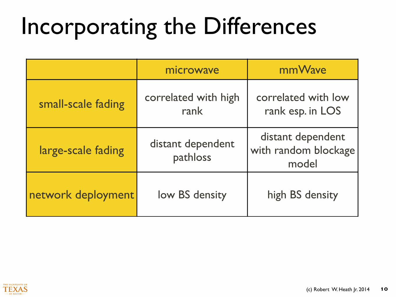
Incorporating the Differences
10
microwave mmWave
small-scale fading correlated with high rank
correlated with low rank esp. in LOS
large-scale fading distant dependent pathloss
distant dependent with random blockage
model
network deployment low BS density high BS density
(c) Robert W. Heath Jr. 2014
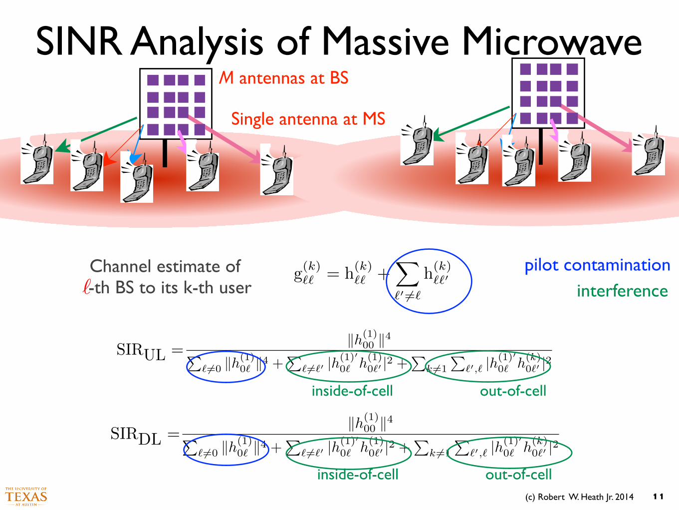
SINR Analysis of Massive Microwave
11
g(k)`` = h(k)`` +X
`0 6=`
h(k)``0Channel estimate of
-th BS to its k-th user`
kh(1)00 k4P
` 6=0 kh(1)0` k4 +
P` 6=`0 |h
(1)0
0` h(1)0`0 |2 +
Pk 6=1
P`0,` |h
(1)0
0` h(k)0`0 |2
SIRUL =
kh(1)00 k4P
` 6=0 kh(1)0` k4 +
P` 6=`0 |h
(1)0
0` h(1)0`0 |2 +
Pk 6=1
P`0,` |h
(1)0
0` h(k)0`0 |2
SIRDL =
pilot contamination
M antennas at BS
Single antenna at MS
interference
inside-of-cell out-of-cell
inside-of-cell out-of-cell
(c) Robert W. Heath Jr. 2014
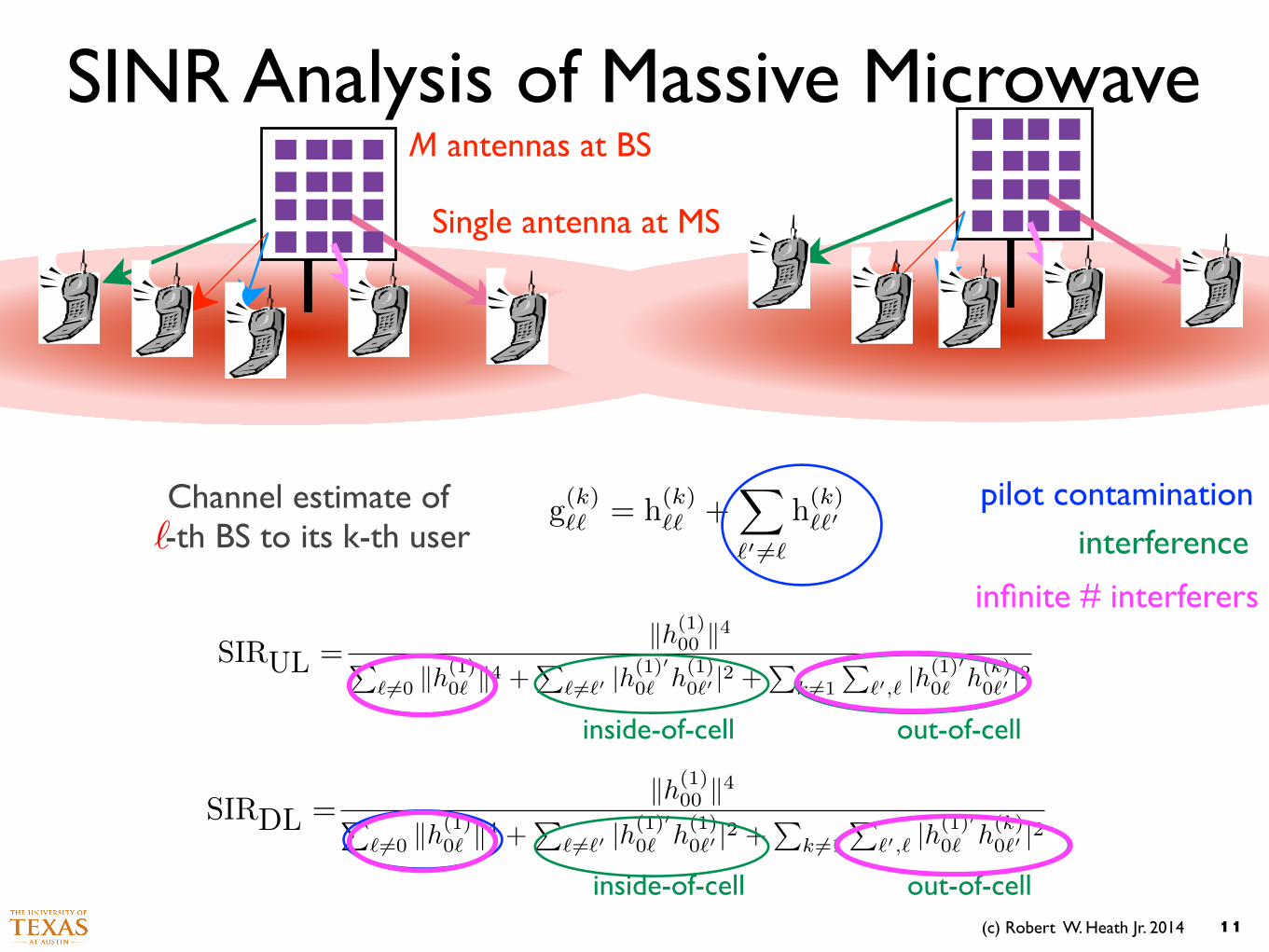
SINR Analysis of Massive Microwave
11
g(k)`` = h(k)`` +X
`0 6=`
h(k)``0Channel estimate of
-th BS to its k-th user`
kh(1)00 k4P
` 6=0 kh(1)0` k4 +
P` 6=`0 |h
(1)0
0` h(1)0`0 |2 +
Pk 6=1
P`0,` |h
(1)0
0` h(k)0`0 |2
SIRUL =
kh(1)00 k4P
` 6=0 kh(1)0` k4 +
P` 6=`0 |h
(1)0
0` h(1)0`0 |2 +
Pk 6=1
P`0,` |h
(1)0
0` h(k)0`0 |2
SIRDL =
pilot contamination
M antennas at BS
Single antenna at MS
interference
inside-of-cell out-of-cell
inside-of-cell out-of-cell
infinite # interferers
(c) Robert W. Heath Jr. 2014
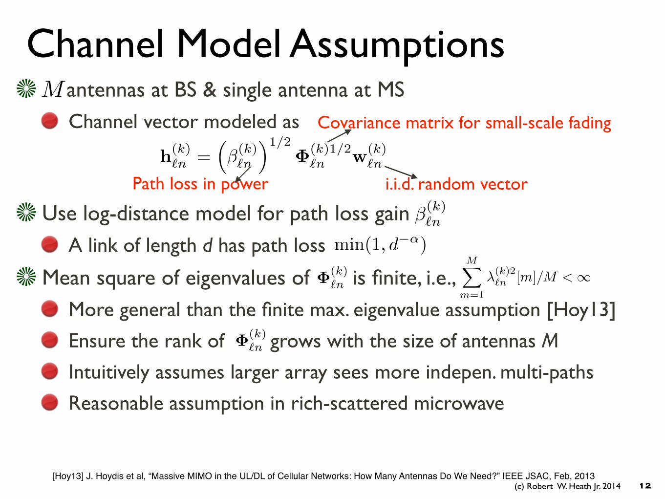
Channel Model Assumptions
12
antennas at BS & single antenna at MS Channel vector modeled as
M
h(k)`n =
⇣�(k)`n
⌘1/2�(k)1/2
`n w(k)`n
Path loss in power
Covariance matrix for small-scale fading
i.i.d. random vector
Use log-distance model for path loss gain A link of length d has path loss
Mean square of eigenvalues of is finite, i.e., More general than the finite max. eigenvalue assumption [Hoy13]
Ensure the rank of grows with the size of antennas M
Intuitively assumes larger array sees more indepen. multi-paths
Reasonable assumption in rich-scattered microwave
min(1, d�↵)
�(k)`n
�(k)`n
MX
m=1
�(k)2`n [m]/M < 1
[Hoy13] J. Hoydis et al, “Massive MIMO in the UL/DL of Cellular Networks: How Many Antennas Do We Need?” IEEE JSAC, Feb, 2013
�(k)`n
(c) Robert W. Heath Jr. 2014
SINR Convergence Results
13T. Bai, R. W. Heath, Jr., “ Asymptotic coverage and rate analysis in massive MIMO cellular networks”, under preparation for submission, May 2014, prior version available on Arxiv
(c) Robert W. Heath Jr. 2014
SINR Convergence Results
13
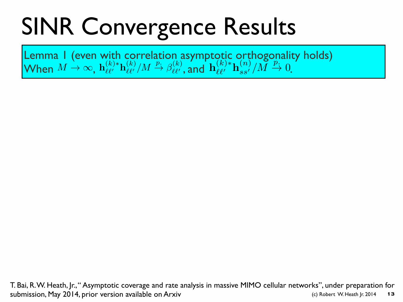
Lemma 1 (even with correlation asymptotic orthogonality holds) When , , and . h(k)⇤
``0 h(k)``0 /M
p.! �(k)``0M ! 1 h(k)⇤
``0 h(n)ss0 /M
p.! 0
T. Bai, R. W. Heath, Jr., “ Asymptotic coverage and rate analysis in massive MIMO cellular networks”, under preparation for submission, May 2014, prior version available on Arxiv
(c) Robert W. Heath Jr. 2014
SINR Convergence Results
13
Lemma 1 (even with correlation asymptotic orthogonality holds) When , , and . h(k)⇤
``0 h(k)``0 /M
p.! �(k)``0M ! 1 h(k)⇤
``0 h(n)ss0 /M
p.! 0
T. Bai, R. W. Heath, Jr., “ Asymptotic coverage and rate analysis in massive MIMO cellular networks”, under preparation for submission, May 2014, prior version available on Arxiv
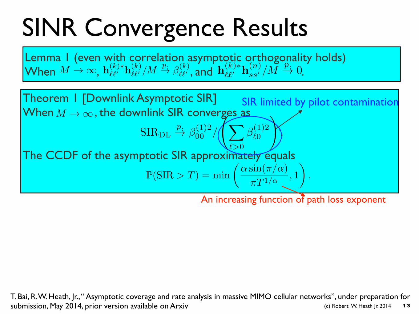
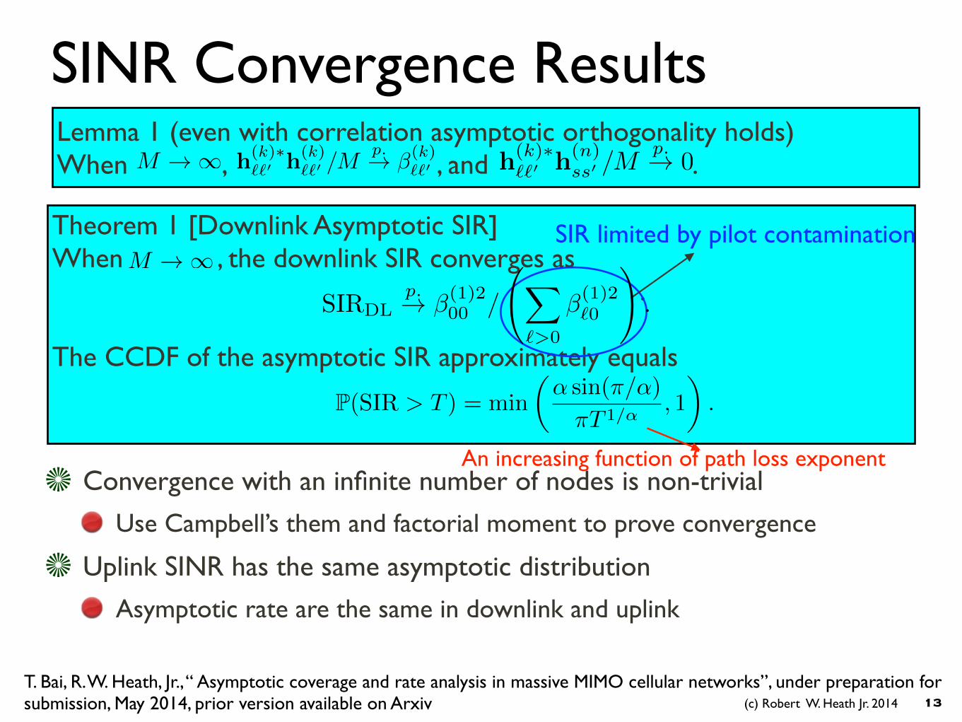
Theorem 1 [Downlink Asymptotic SIR] When , the downlink SIR converges as . The CCDF of the asymptotic SIR approximately equals
P(SIR > T ) = min
✓↵ sin(⇡/↵)
⇡T 1/↵, 1
◆.
M ! 1SIR limited by pilot contamination
An increasing function of path loss exponent
SIRDLp.! �(1)2
00 /
X
`>0
�(1)2`0
!.
(c) Robert W. Heath Jr. 2014
SINR Convergence Results
13
Convergence with an infinite number of nodes is non-trivial
Use Campbell’s them and factorial moment to prove convergence
Uplink SINR has the same asymptotic distribution
Asymptotic rate are the same in downlink and uplink
Lemma 1 (even with correlation asymptotic orthogonality holds) When , , and . h(k)⇤
``0 h(k)``0 /M
p.! �(k)``0M ! 1 h(k)⇤
``0 h(n)ss0 /M
p.! 0
T. Bai, R. W. Heath, Jr., “ Asymptotic coverage and rate analysis in massive MIMO cellular networks”, under preparation for submission, May 2014, prior version available on Arxiv
Theorem 1 [Downlink Asymptotic SIR] When , the downlink SIR converges as . The CCDF of the asymptotic SIR approximately equals
P(SIR > T ) = min
✓↵ sin(⇡/↵)
⇡T 1/↵, 1
◆.
M ! 1SIR limited by pilot contamination
An increasing function of path loss exponent
SIRDLp.! �(1)2
00 /
X
`>0
�(1)2`0
!.
(c) Robert W. Heath Jr. 2014
−10 −5 0 5 10 15 20 25 30 35 400
0.1
0.2
0.3
0.4
0.5
0.6
0.7
0.8
0.9
1
SINR Threshold in dB
Cov
erag
e Pr
obab
ility
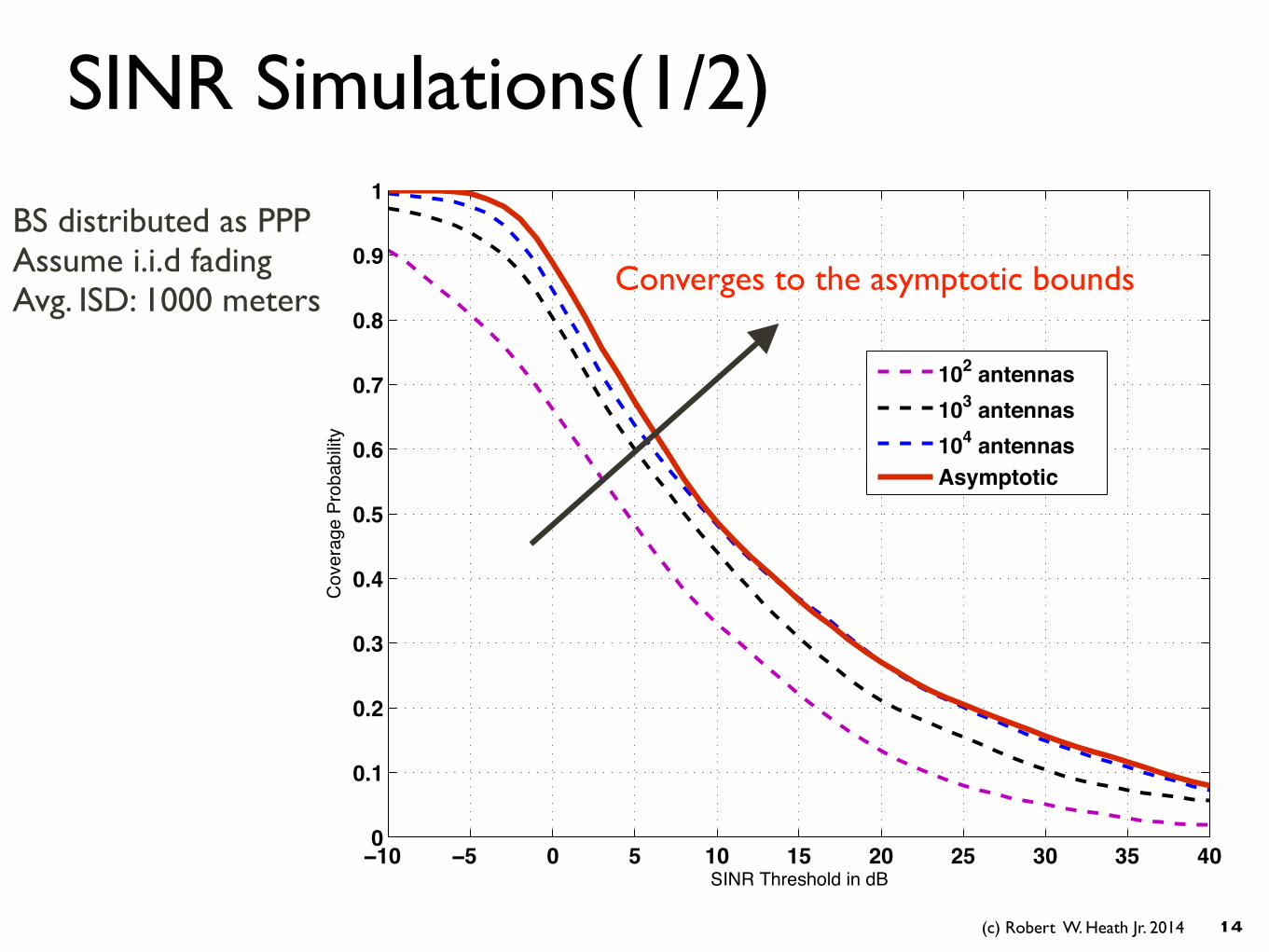
102 antennas103 antennas104 antennasAsymptotic
SINR Simulations(1/2)
14
BS distributed as PPP Assume i.i.d fading Avg. ISD: 1000 meters
Converges to the asymptotic bounds
(c) Robert W. Heath Jr. 2014
−10 −5 0 5 10 15 20 25 30 35 400
0.1
0.2
0.3
0.4
0.5
0.6
0.7
0.8
0.9
1
SINR threshold in dB
SIN
R C
over
age
prob
abilit
y
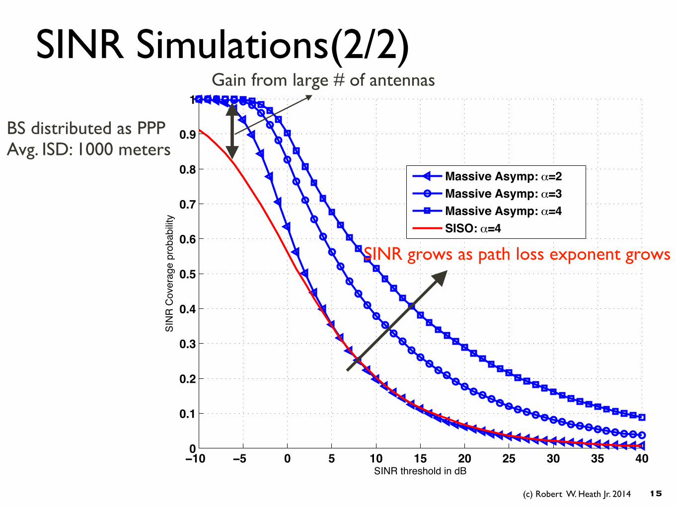
Massive Asymp: _=2Massive Asymp: _=3Massive Asymp: _=4SISO: _=4
SINR Simulations(2/2)
15
Gain from large # of antennas
BS distributed as PPP Avg. ISD: 1000 meters
SINR grows as path loss exponent grows
(c) Robert W. Heath Jr. 2014
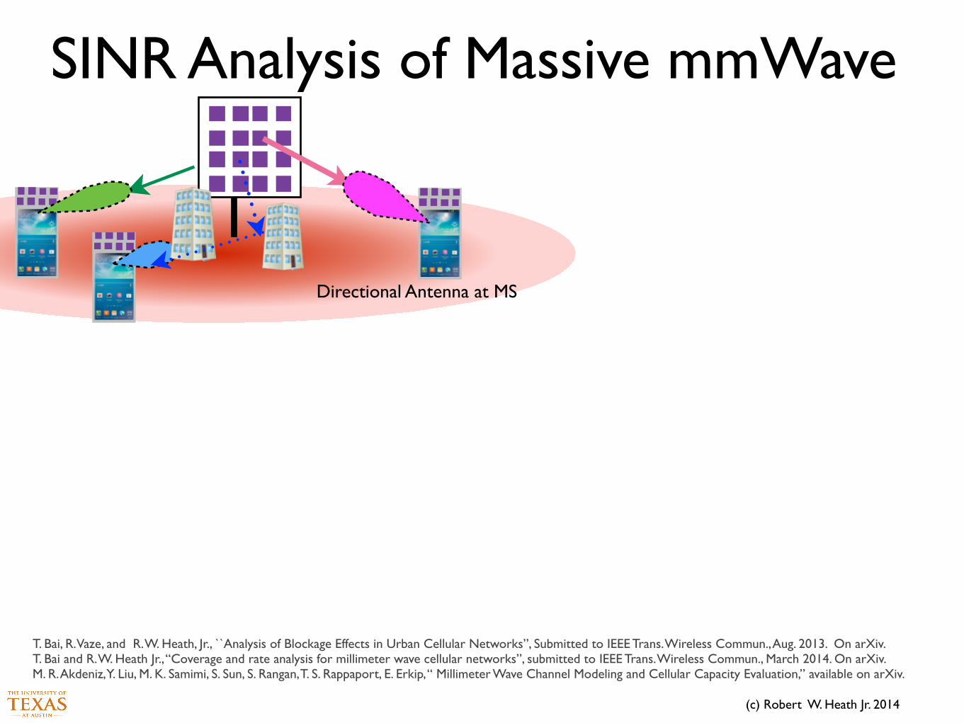
SINR Analysis of Massive mmWave
Directional Antenna at MS
T. Bai, R. Vaze, and R. W. Heath, Jr., ``Analysis of Blockage Effects in Urban Cellular Networks”, Submitted to IEEE Trans. Wireless Commun., Aug. 2013. On arXiv. T. Bai and R. W. Heath Jr., “Coverage and rate analysis for millimeter wave cellular networks”, submitted to IEEE Trans. Wireless Commun., March 2014. On arXiv. M. R. Akdeniz, Y. Liu, M. K. Samimi, S. Sun, S. Rangan, T. S. Rappaport, E. Erkip, “ Millimeter Wave Channel Modeling and Cellular Capacity Evaluation,” available on arXiv.
(c) Robert W. Heath Jr. 2014
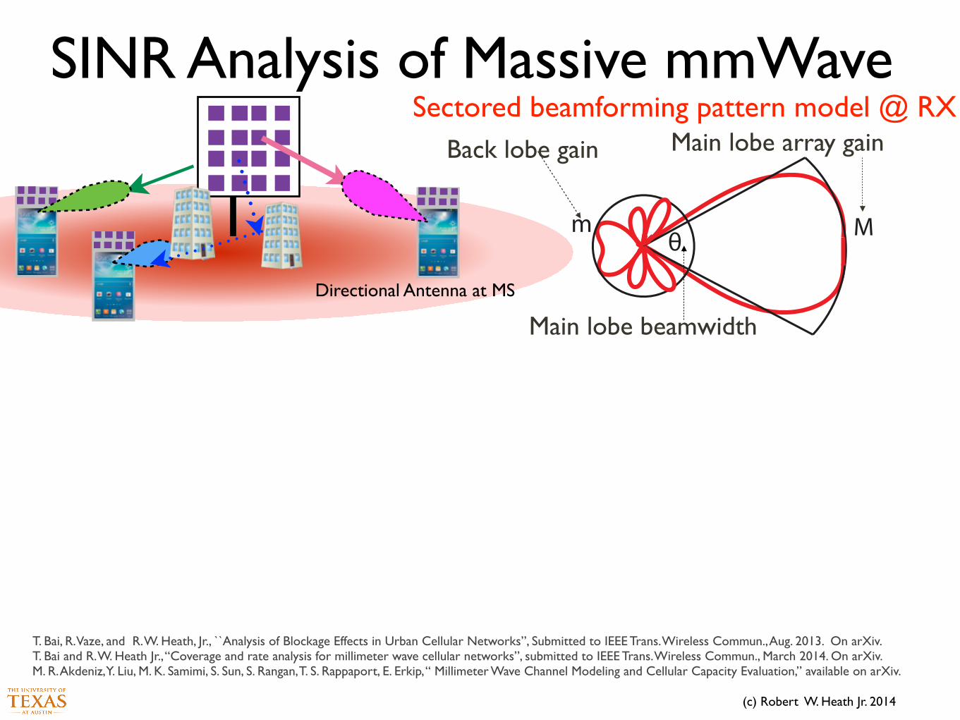
SINR Analysis of Massive mmWave
Directional Antenna at MS
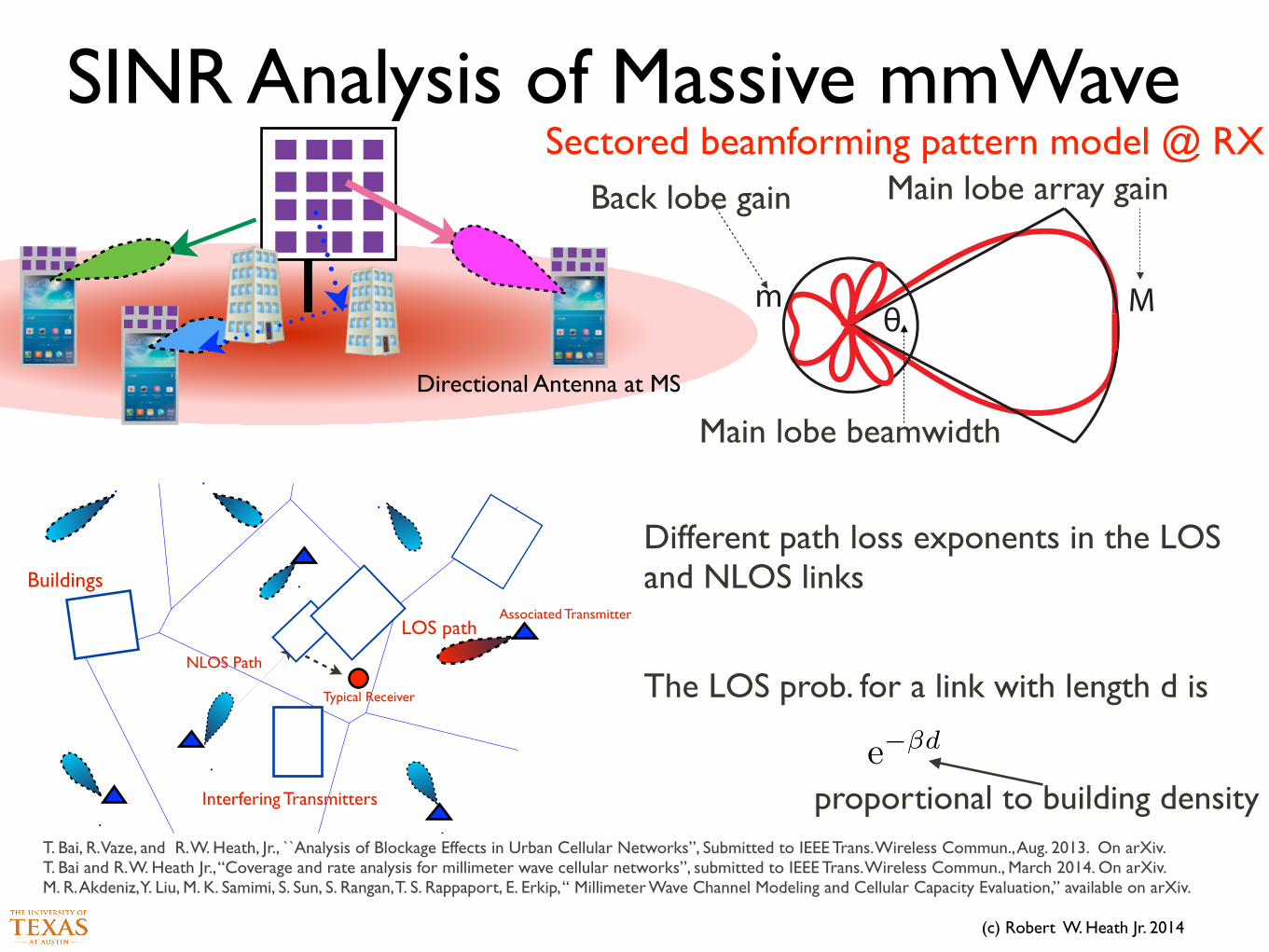
Sectored beamforming pattern model @ RX
5
[2], we also remove the constraint that the LOS path loss exponent is 2, and extend the results
in [2] to general path loss exponents, in addition to providing derivations for all results, and new
simulation results.
This paper is organized as follows. We introduce the system model in Section II. We derive
expressions for the SINR and rate coverage in a general mmWave network in Section III. A
systematic approach is also proposed to approximate general LOS probability functions as a step
function to further simplify analysis. In Section IV, we apply the simplified system model to
analyze performance and examine asymptotic trends in dense mmWave networks, where outdoor
users observe more than one LOS base stations with high probability. Finally, conclusions and
suggestions for future work are provided in Section V.
II. SYSTEM MODEL
(a) System model for mmWave cellular networks
Mmθ
(b) Sectored model to approximate beamforming patterns.
Fig. 1: In (a), we illustrate the proposed system model for mmWave cellular networks. Blockages are modeled as a random
process of rectangles, while base stations are assumed to be distributed as a Poisson point process on the plane. An outdoor
typical user is fixed at the origin, and the base stations can be categorized into three groups: indoor base stations, outdoor base
stations that is LOS to the typical user, and outdoor base station NLOS to the user. Directional beamforming is performed at
both base stations and mobile stations to exploit directivity gains. In (b), we illustrate the sectored antenna model G
M,m,✓
,
which is used to approximate the beamforming patterns.
In this section, we introduce our system model for evaluating the performance of a mmWave
network. We focus on the downlink coverage and rate performance experienced by an outdoor
user, as illustrated in Fig. 1(a). We make the following assumptions when formulating the system
model.
Main lobe beamwidth
Main lobe array gainBack lobe gain
T. Bai, R. Vaze, and R. W. Heath, Jr., ``Analysis of Blockage Effects in Urban Cellular Networks”, Submitted to IEEE Trans. Wireless Commun., Aug. 2013. On arXiv. T. Bai and R. W. Heath Jr., “Coverage and rate analysis for millimeter wave cellular networks”, submitted to IEEE Trans. Wireless Commun., March 2014. On arXiv. M. R. Akdeniz, Y. Liu, M. K. Samimi, S. Sun, S. Rangan, T. S. Rappaport, E. Erkip, “ Millimeter Wave Channel Modeling and Cellular Capacity Evaluation,” available on arXiv.
(c) Robert W. Heath Jr. 2014
SINR Analysis of Massive mmWave
Directional Antenna at MS
Sectored beamforming pattern model @ RX
5
[2], we also remove the constraint that the LOS path loss exponent is 2, and extend the results
in [2] to general path loss exponents, in addition to providing derivations for all results, and new
simulation results.
This paper is organized as follows. We introduce the system model in Section II. We derive
expressions for the SINR and rate coverage in a general mmWave network in Section III. A
systematic approach is also proposed to approximate general LOS probability functions as a step
function to further simplify analysis. In Section IV, we apply the simplified system model to
analyze performance and examine asymptotic trends in dense mmWave networks, where outdoor
users observe more than one LOS base stations with high probability. Finally, conclusions and
suggestions for future work are provided in Section V.
II. SYSTEM MODEL
(a) System model for mmWave cellular networks
Mmθ
(b) Sectored model to approximate beamforming patterns.
Fig. 1: In (a), we illustrate the proposed system model for mmWave cellular networks. Blockages are modeled as a random
process of rectangles, while base stations are assumed to be distributed as a Poisson point process on the plane. An outdoor
typical user is fixed at the origin, and the base stations can be categorized into three groups: indoor base stations, outdoor base
stations that is LOS to the typical user, and outdoor base station NLOS to the user. Directional beamforming is performed at
both base stations and mobile stations to exploit directivity gains. In (b), we illustrate the sectored antenna model G
M,m,✓
,
which is used to approximate the beamforming patterns.
In this section, we introduce our system model for evaluating the performance of a mmWave
network. We focus on the downlink coverage and rate performance experienced by an outdoor
user, as illustrated in Fig. 1(a). We make the following assumptions when formulating the system
model.
Main lobe beamwidth
Main lobe array gainBack lobe gain
T. Bai, R. Vaze, and R. W. Heath, Jr., ``Analysis of Blockage Effects in Urban Cellular Networks”, Submitted to IEEE Trans. Wireless Commun., Aug. 2013. On arXiv. T. Bai and R. W. Heath Jr., “Coverage and rate analysis for millimeter wave cellular networks”, submitted to IEEE Trans. Wireless Commun., March 2014. On arXiv. M. R. Akdeniz, Y. Liu, M. K. Samimi, S. Sun, S. Rangan, T. S. Rappaport, E. Erkip, “ Millimeter Wave Channel Modeling and Cellular Capacity Evaluation,” available on arXiv.
15
Fig. 8. .
Interfering Transmitters
Associated Transmitter
Buildings
Typical Receiver
NLOS Path
LOS path
Different path loss exponents in the LOS and NLOS links
!The LOS prob. for a link with length d is
e��d
proportional to building density
(c) Robert W. Heath Jr. 2014
Channel Model Assumptions
17
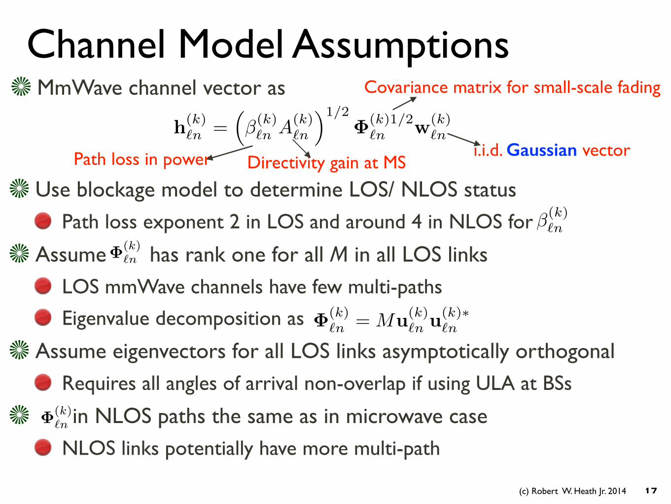
MmWave channel vector as
Path loss in power
Covariance matrix for small-scale fading
i.i.d. Gaussian vector
Use blockage model to determine LOS/ NLOS status Path loss exponent 2 in LOS and around 4 in NLOS for
Assume has rank one for all M in all LOS links LOS mmWave channels have few multi-paths
Eigenvalue decomposition as
Assume eigenvectors for all LOS links asymptotically orthogonal Requires all angles of arrival non-overlap if using ULA at BSs
in NLOS paths the same as in microwave case NLOS links potentially have more multi-path
�(k)`n
�(k)`n
h(k)`n =
⇣�(k)`n A(k)
`n
⌘1/2�(k)1/2
`n w(k)`n
Directivity gain at MS
�(k)`n = Mu(k)
`n u(k)⇤`n
�(k)`n
(c) Robert W. Heath Jr. 2014
SINR Convergence Results
18* T. Bai, R. W. Heath, Jr., “ Asymptotic coverage and rate analysis in massive MIMO cellular networks”, to be submitted soon, prior version available on Arxiv
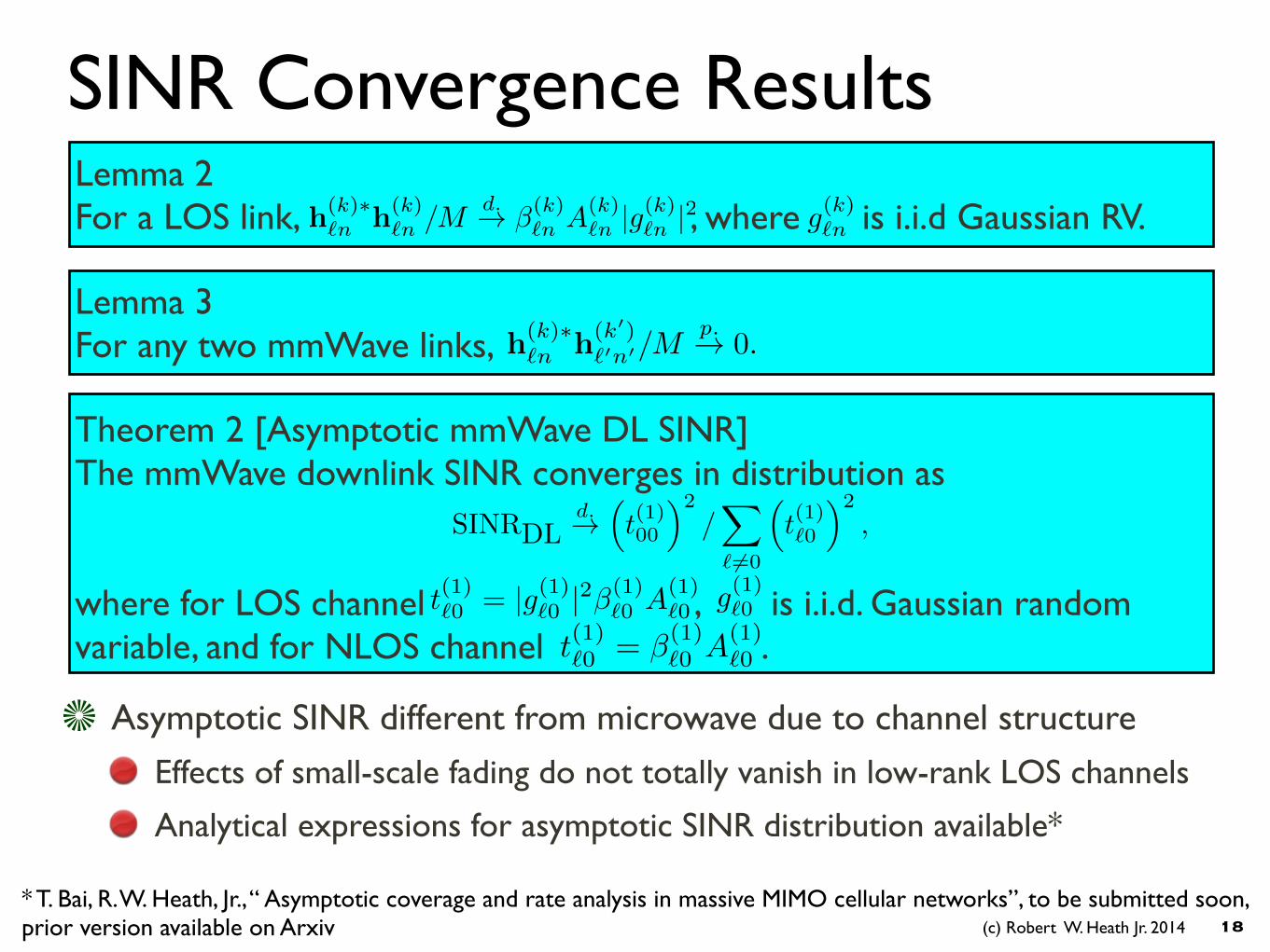
Lemma 2 For a LOS link, , where is i.i.d Gaussian RV. g(k)`n
Lemma 3 For any two mmWave links, h(k)⇤
`n h(k0)`0n0/M
p.! 0.
Theorem 2 [Asymptotic mmWave DL SINR] The mmWave downlink SINR converges in distribution as !!where for LOS channel , is i.i.d. Gaussian random variable, and for NLOS channel .
g(1)`0
SINRDLd.!
⇣t(1)00
⌘2/X
` 6=0
⇣t(1)`0
⌘2,
Asymptotic SINR different from microwave due to channel structure
Effects of small-scale fading do not totally vanish in low-rank LOS channels
Analytical expressions for asymptotic SINR distribution available*
h(k)⇤`n h(k)
`n /Md.! �(k)
`n A(k)`n |g(k)`n |2
t(1)`0 = |g(1)`0 |2�(1)`0 A(1)
`0
t(1)`0 = �(1)`0 A(1)
`0
(c) Robert W. Heath Jr. 2014
−10 −5 0 5 10 15 20 250
0.1
0.2
0.3
0.4
0.5
0.6
0.7
0.8
0.9
SINR Threshold in dB
Cov
erag
e Pr
obab
ility
Asymptotic102 antennas103 antennas104 antennas
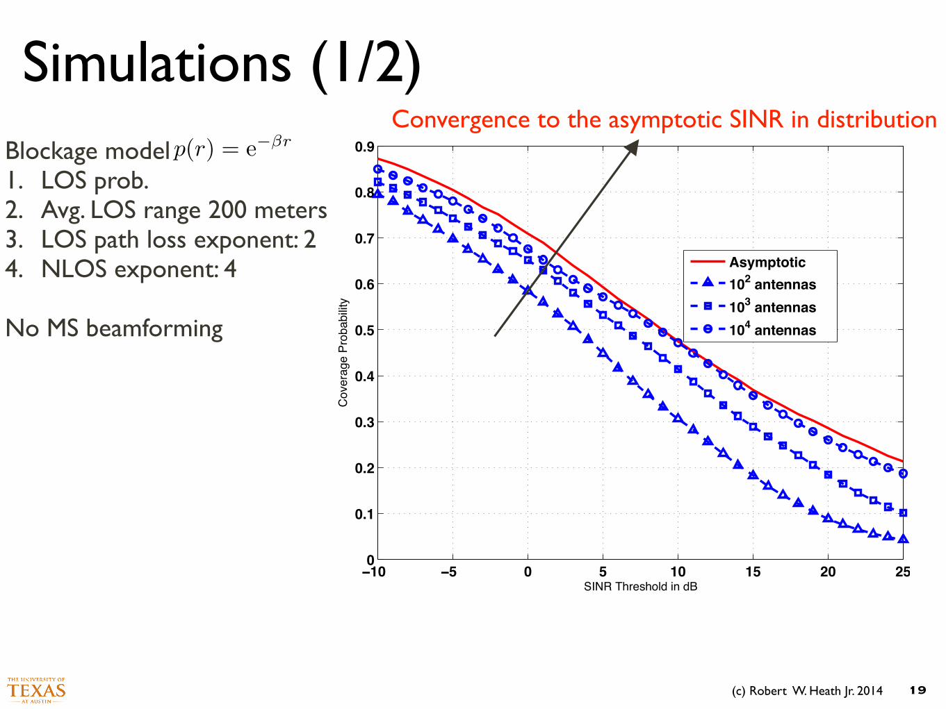
Simulations (1/2)
19
Blockage model 1. LOS prob. 2. Avg. LOS range 200 meters 3. LOS path loss exponent: 2 4. NLOS exponent: 4 !No MS beamforming
p(r) = e��rConvergence to the asymptotic SINR in distribution
(c) Robert W. Heath Jr. 2014
Simulations (2/2)
20
−10 −5 0 5 10 15 20 25 30 35 400
0.1
0.2
0.3
0.4
0.5
0.6
0.7
0.8
0.9
1
SINR Threshold in dB
SIN
R C
over
age
Prob
abilit
y
ISD:100 mISD:200 mISD: 400 mall NLOSall LOSISD: 200 m + 10dB BF gain
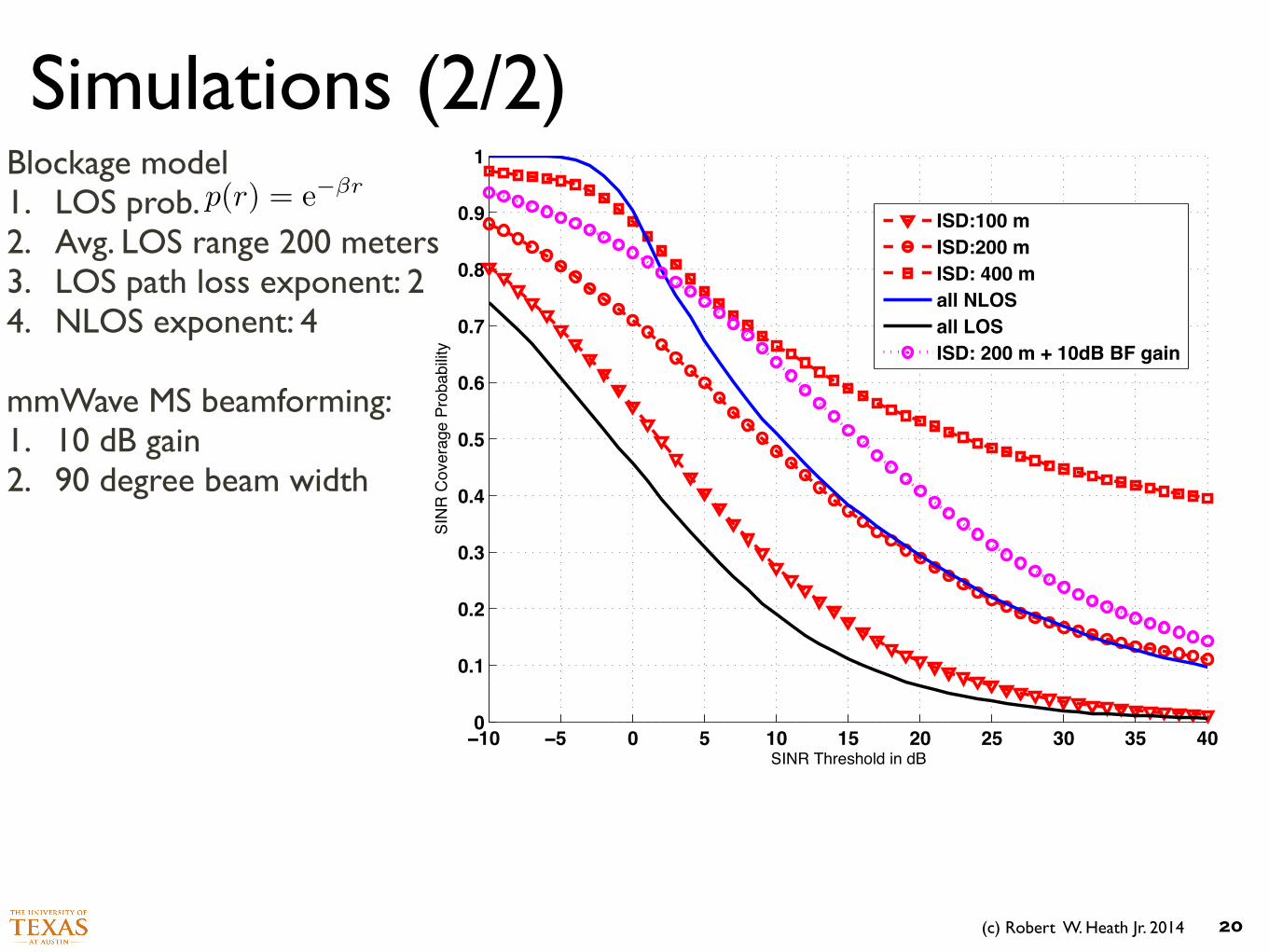
Blockage model 1. LOS prob. 2. Avg. LOS range 200 meters 3. LOS path loss exponent: 2 4. NLOS exponent: 4 !mmWave MS beamforming: 1. 10 dB gain 2. 90 degree beam width
p(r) = e��r
(c) Robert W. Heath Jr. 2014
Simulations (2/2)
20
−10 −5 0 5 10 15 20 25 30 35 400
0.1
0.2
0.3
0.4
0.5
0.6
0.7
0.8
0.9
1
SINR Threshold in dB
SIN
R C
over
age
Prob
abilit
y
ISD:100 mISD:200 mISD: 400 mall NLOSall LOSISD: 200 m + 10dB BF gain
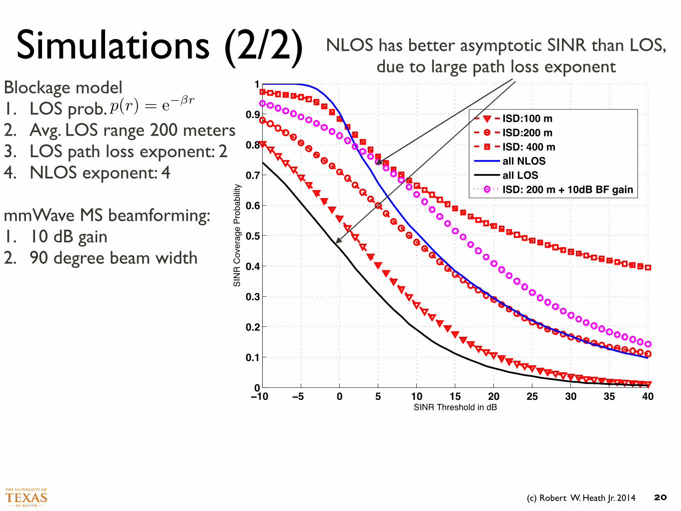
Blockage model 1. LOS prob. 2. Avg. LOS range 200 meters 3. LOS path loss exponent: 2 4. NLOS exponent: 4 !mmWave MS beamforming: 1. 10 dB gain 2. 90 degree beam width
p(r) = e��r
NLOS has better asymptotic SINR than LOS, due to large path loss exponent
(c) Robert W. Heath Jr. 2014
Simulations (2/2)
20
−10 −5 0 5 10 15 20 25 30 35 400
0.1
0.2
0.3
0.4
0.5
0.6
0.7
0.8
0.9
1
SINR Threshold in dB
SIN
R C
over
age
Prob
abilit
y
ISD:100 mISD:200 mISD: 400 mall NLOSall LOSISD: 200 m + 10dB BF gain
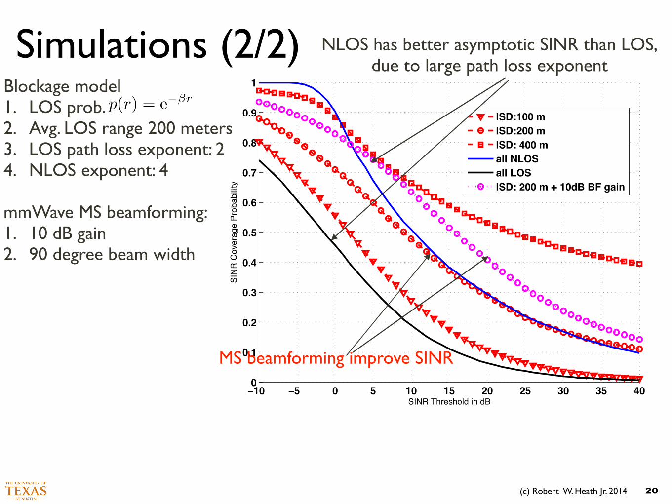
Blockage model 1. LOS prob. 2. Avg. LOS range 200 meters 3. LOS path loss exponent: 2 4. NLOS exponent: 4 !mmWave MS beamforming: 1. 10 dB gain 2. 90 degree beam width
p(r) = e��r
NLOS has better asymptotic SINR than LOS, due to large path loss exponent
MS beamforming improve SINR
(c) Robert W. Heath Jr. 2014
Simulations (2/2)
20
−10 −5 0 5 10 15 20 25 30 35 400
0.1
0.2
0.3
0.4
0.5
0.6
0.7
0.8
0.9
1
SINR Threshold in dB
SIN
R C
over
age
Prob
abilit
y
ISD:100 mISD:200 mISD: 400 mall NLOSall LOSISD: 200 m + 10dB BF gain
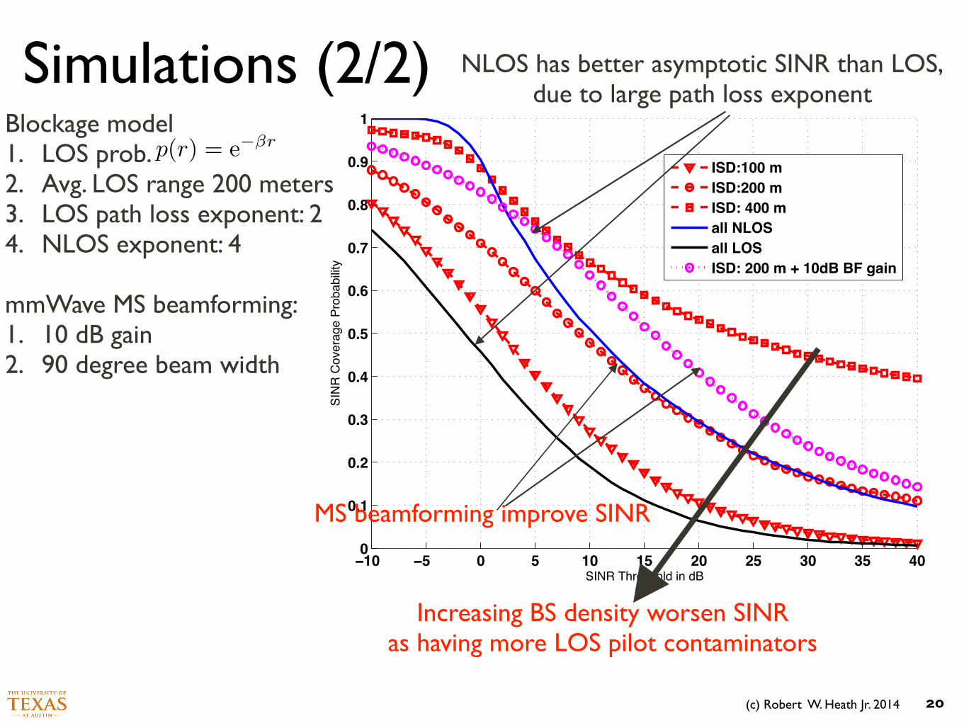
Blockage model 1. LOS prob. 2. Avg. LOS range 200 meters 3. LOS path loss exponent: 2 4. NLOS exponent: 4 !mmWave MS beamforming: 1. 10 dB gain 2. 90 degree beam width
p(r) = e��r
NLOS has better asymptotic SINR than LOS, due to large path loss exponent
MS beamforming improve SINR
Increasing BS density worsen SINR as having more LOS pilot contaminators
(c) Robert W. Heath Jr. 2014
−10 −5 0 5 10 15 20 25 30 35 400
0.1
0.2
0.3
0.4
0.5
0.6
0.7
0.8
0.9
1
SINR Threshold in dB
SIN
R C
over
age
Prob
abilit
y
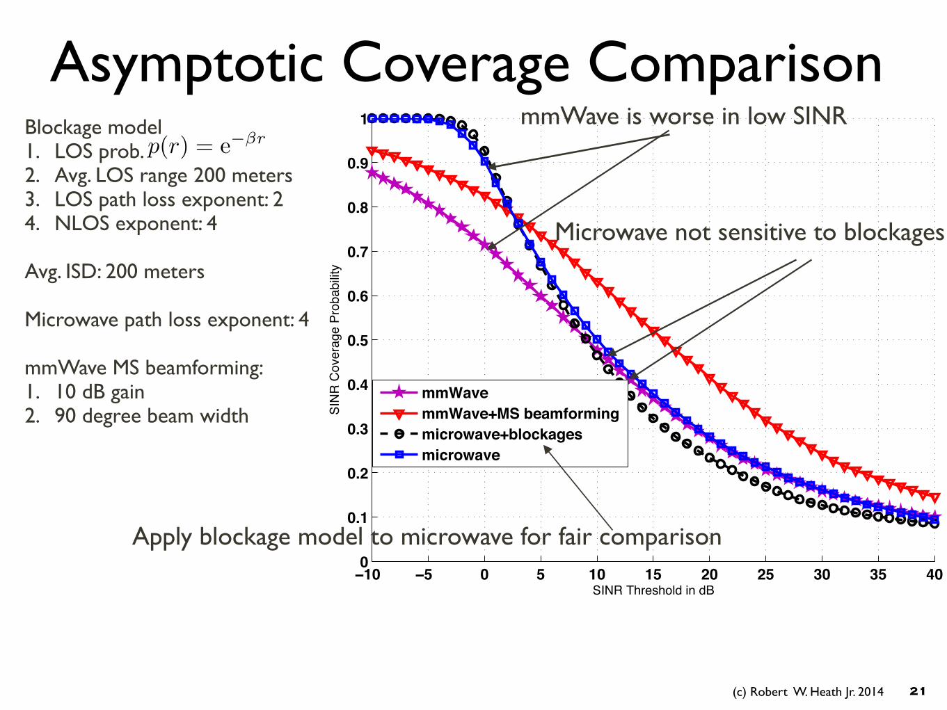
mmWavemmWave+MS beamformingmicrowave+blockagesmicrowave
Asymptotic Coverage Comparison
21
mmWave is worse in low SINRBlockage model 1. LOS prob. 2. Avg. LOS range 200 meters 3. LOS path loss exponent: 2 4. NLOS exponent: 4 !Avg. ISD: 200 meters !Microwave path loss exponent: 4 !mmWave MS beamforming: 1. 10 dB gain 2. 90 degree beam width
p(r) = e��r
Microwave not sensitive to blockages
Apply blockage model to microwave for fair comparison
(c) Robert W. Heath Jr. 2014
−10 −5 0 5 10 15 20 25 30 35 400
0.1
0.2
0.3
0.4
0.5
0.6
0.7
0.8
SINR threshold in dB
SIN
R C
over
age
Prob
abilit
y
Microwave 64 antennasMmWave 16 antennasMmWave 128 antennas
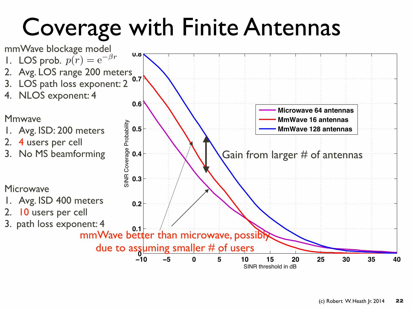
Coverage with Finite Antennas
22
mmWave blockage model 1. LOS prob. 2. Avg. LOS range 200 meters 3. LOS path loss exponent: 2 4. NLOS exponent: 4 !Mmwave 1. Avg. ISD: 200 meters 2. 4 users per cell 3. No MS beamforming !!Microwave 1. Avg. ISD 400 meters 2. 10 users per cell 3. path loss exponent: 4 !
p(r) = e��r
Gain from larger # of antennas
mmWave better than microwave, possibly due to assuming smaller # of users
(c) Robert W. Heath Jr. 2014
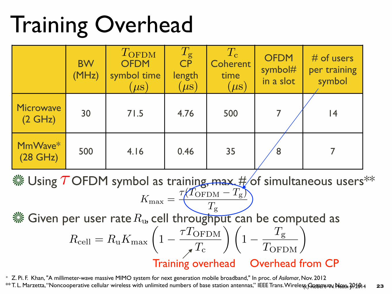
Training Overhead
Using OFDM symbol as training, max. # of simultaneous users**
23
* Z. Pi. F. Khan, "A millimeter-wave massive MIMO system for next generation mobile broadband," In proc. of Asilomar, Nov. 2012 ** T. L. Marzetta, “Noncooperative cellular wireless with unlimited numbers of base station antennas,” IEEE Trans. Wireless Commun., Nov., 2010.
⌧Kmax =
⌧(TOFDM � Tg)
Tg
Given per user rate , cell throughput can be computed asRu
BW (MHz)
OFDM symbol time
CP length
Coherent time
OFDM symbol# in a slot
# of users per training
symbol
Microwave (2 GHz)
30 71.5 4.76 500 7 14
MmWave* (28 GHz)
500 4.16 0.46 35 8 7
(µs)(µs) (µs)
TgTOFDM Tc
Training overhead
Rcell = RuKmax
✓1� ⌧TOFDM
Tc
◆✓1� Tg
TOFDM
◆
Overhead from CP
(c) Robert W. Heath Jr. 2014
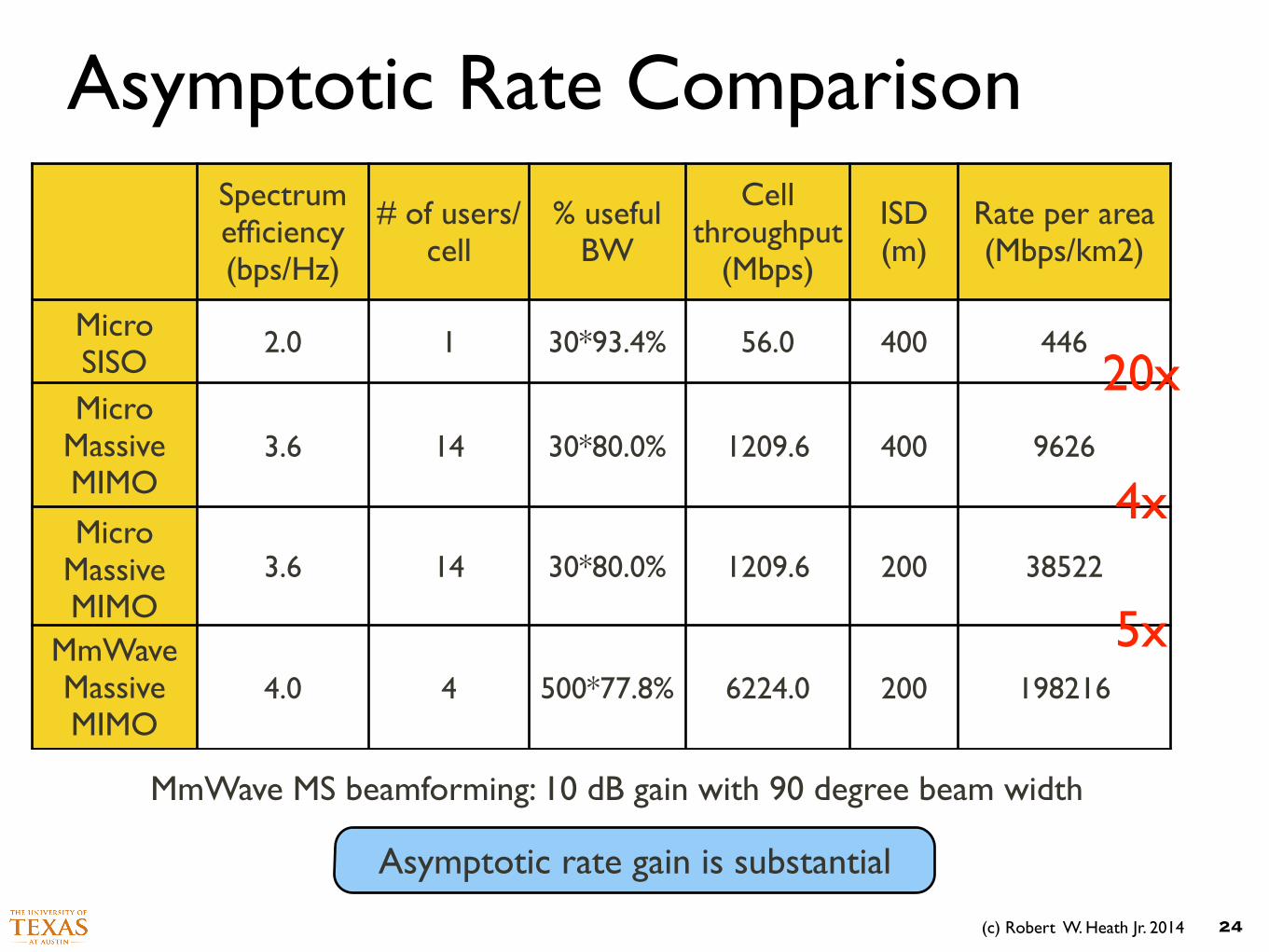
Asymptotic Rate Comparison
24
Spectrum efficiency (bps/Hz)
# of users/cell
% useful BW
Cell throughput
(Mbps)
ISD (m)
Rate per area (Mbps/km2)
Micro SISO
2.0 1 30*93.4% 56.0 400 446
Micro Massive MIMO
3.6 14 30*80.0% 1209.6 400 9626
Micro Massive MIMO
3.6 14 30*80.0% 1209.6 200 38522
MmWave Massive MIMO
4.0 4 500*77.8% 6224.0 200 198216
MmWave MS beamforming: 10 dB gain with 90 degree beam width
Asymptotic rate gain is substantial
20x
4x
5x
(c) Robert W. Heath Jr. 2014
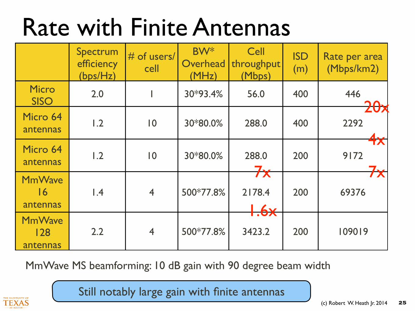
Rate with Finite Antennas
25
MmWave MS beamforming: 10 dB gain with 90 degree beam width
Still notably large gain with finite antennas
Spectrum efficiency (bps/Hz)
# of users/cell
BW* Overhead
(MHz)
Cell throughput
(Mbps)
ISD (m)
Rate per area (Mbps/km2)
Micro SISO
2.0 1 30*93.4% 56.0 400 446
Micro 64 antennas 1.2 10 30*80.0% 288.0 400 2292
Micro 64 antennas 1.2 10 30*80.0% 288.0 200 9172
MmWave 16
antennas1.4 4 500*77.8% 2178.4 200 69376
MmWave 128
antennas2.2 4 500*77.8% 3423.2 200 109019
20x
4x
7x7x
1.6x

Conclusion
Go Massive


![Research Article SDN Controlled mmWave Massive MIMO Hybrid ...downloads.hindawi.com/journals/misy/2016/9767065.pdf · massive MIMO systems [ , ]. Nevertheless, the development of](https://img.dokumen.tips/doc/110x75/5f76bbf22d75835b156df745/research-article-sdn-controlled-mmwave-massive-mimo-hybrid-massive-mimo-systems.jpg)