Embed Size (px)
Citation preview

Comparative study of wind tunnel test results to international and Egyptian design codes
*Chang- Abdulmonem A. Badri1), *Manar M. Hussein2) and Walid A. Attia3)
1), 2), 3) 1Department of Structural Engineering, Cairo University, Giza, Egypt 2) [email protected]
ABSTRACT
International codes that have been developed for evaluating wind loads on structures, could not capture the wind structure interaction due to the gusty nature of wind and the dynamic behavior of structures. Therefore, the alternative wind tunnel testing was introduced. In this paper, a comparative study between different codes: the Egyptian code, EC Draft 201-08, ASCE 7-05, BS 6399-2, and wind tunnel test results was conducted. An investigation has been carried out on two case studies tall buildings located within the Arabian Gulf region using (ETABS) software for wind loads in the along and across wind directions. Results for the main structural responses: including stories forces, shears, overturning moments, lateral displacements, and drifts were presented graphically. The conclusions and recommendations for future works help improving Egyptian code provisions and show limitations for different cases. 1. INTRODUCTION In the past few decades, several international building codes and standards have been developed and established for evaluating the effect of wind loads on flexible tall buildings, taking into account the influence of structural geometry, surrounding constructions, terrain and site exposures, and wind characteristics as well. However, the actual wind structure interaction was not always accurately captured by these standards due to the gusty nature of wind flow and the complicated dynamic behavior of structures. Building exposure with respect to surrounding structures could have major impact on the applied wind loads according to different structural shape, which is not exactly captured by codes. Therefore, irregular structural shapes and complex geometries are not recommended to be studied by the codes conventional procedures. As a result of the above, the need for alternative methods to evaluate wind loads on buildings and other structures became a must in order to give accurate wind pressures
1) Graduate Student 2) Associate professor 3) Professor
on super tall buildings and special structures which are not often covered by these standards. Thus, the wind tunnel testing (WTT) of structures was introduced, which is the most accurate method used to evaluate wind loads on all types of buildings and structures. (McNamara 2001) checked the Massachusetts State Building Code and National Building Code BOCA 93. It was concluded that wind tunnel predicts more pressure at 100 m and above, but diminished quickly on lower floors. In 2002, (Yin Zhou 2002) presented a comprehensive assessment of the source of results scatter in the along wind loads recommended by major international codes including the ASCE 7-98, AS 1170.2-89, NBC 1995, AIJ 1993, and Eurocode 1993. It was noted that this scatter arises primarily from variations in the definition of wind field characteristics in the respective codes and standards. A theoretical study by (Boggs 2005) stated through that building codes procedures are based on general assumptions, which are usually but not always conservative, and do not provide accurate wind loads because of exposure conditions, directional properties of the wind climate, complex geometrical shapes, torsion, aerodynamic interactions, and load combinations. However, structural reliability under wind loading improves significantly with wind tunnel study, which is capable of more accurate load definition and can be addressed in terms of loading and serviceability limit states. Then, (Bhami 2009) compared the Indian standard (IS 875) and code (NBC 2005) for wind induced loads to the wind tunnel test data. The results indicate that IS 875 pressure values on edges stand much lower than wind tunnel test and ASCE figures. In this research, a comparative study was conducted between the ASCE 7-05, BS 6399-2, and EC Draft 201-08 codes analytical procedures, as well as the wind tunnel experimental tests, for evaluating the wind induced lateral loads in the along and across wind directions. The conclusions obtained and the recommendations for future work were all presented in later section. 2. MAIN OBJECTIVES In this research, two study cases tall buildings located within the Arabian Gulf region, and having a height range of 200 to 300 m, were selected to establish a comparative study between the codes analytical methods and the wind tunnels experimental test results. Their plans are rectangle, near rectangle, or near triangle. The main scope and objectives of this study can be summarized in the following points:
1. To present an introduction to the wind engineering problem, including explanations of the wind climate and characteristics.
2. To review the historical works and literature studies made on comparing wind tunnel tests results to the corresponding international codes values.
3. To produce numerical models using (ETABS) software, in order to obtain the along and across wind structural responses for each case study.
4. To illustrate graphically a comparative study between the ASCE 7-05, the BS 6399-2, the EC Draft 201-08, and the wind tunnel tests outputs.
3. WIND ENGINEERING APPROACHES
Several international buildings codes of practice give their own limitations and recommendations for calculating wind loads of structures, which correspond to the local wind climate and exposure category of each region. Out of these international codes, two majors were selected to discuss in detail their provisions for wind loads on buildings, along with the Egyptian Draft Code, in order to be compared to the wind tunnel results:
1. American Society for Civil Engineers: Minimum Design Loads for Buildings and Other Structures (ASCE/SEI 7-05: Chapter 6: Wind Loads 2006).
2. British Standard: Loading for Buildings (BS 6399-2: 1997 corrected 2002: Part 2: Code of Practice for Wind Loads 1997).
3. The Egyptian Draft Code for Calculating Loads and Forces in Buildings and Structural Works (EC Draft 201-08: Chapter 7: Wind Loads 2008).
4. Wind Tunnel Testing (WTT) Method. 3.1 ASCE/SEI 7-05 ASCE 7-05 gives three procedures for calculating wind loads on buildings:
1. Method 1: Simplified Procedure. 2. Method 2: Analytical Procedure. 3. Method 3: Wind Tunnel Procedure.
Method 1, the simplified procedure, is restricted to regular shaped buildings with a maximum height of 18 m. This method gives the wind pressures on buildings directly without calculations when the building meets the above conditions. Method 2, the analytical procedure, can be used for high rise buildings that are regular in shape, but they should not be sensitive to cross wind loading, vortex shedding, instability due to galloping or flutter; and does not have a site location for which channeling effects or buffeting warrant special consideration. This method applies to a majority of buildings, as it is taking into account most of the main factors related to the wind engineering problem. Method 3, the wind tunnel procedure, which is recommended for buildings with irregular and complex shapes, flexible with natural frequencies less than 1 Hz, subject to cross wind loading and vortex shedding or where a more accurate wind pressure distribution is desired. In this study, the analytical procedure is applied and the design wind loads for buildings at height Z above ground level was determined according to the following equation (1) (ASCE/SEI 7-05 2006).
P = qz Gf Cp (windward) + qh Gf Cpi (leeward) (1)
Where, Gf is the gust effect factor that accounts for the dynamic amplification of loading in the along wind direction due to wind turbulence and structure interaction. There are three methods for calculating the gust effect factor (Gf) in (ASCE/SEI 7-05 2006) depending on structure rigidity. The external pressure coefficients (Cp) and the internal pressure coefficients (Cpi) shall be determined from Tables in (ASCE/SEI 7-05 2006). The velocity wind pressure qz at height Z and the velocity suction qh are given by equations in (ASCE/SEI 7-05 2006).

(Gf) does not include allowances for the across wind loading effects, vortex shedding, and instability due to galloping, flutter, or dynamic torsion effects. Buildings susceptible to these effects should be designed using the wind tunnel test results. 3.2 BS 6399-2: 1997 Two methods are introduced by the BS 6399-2: 1997 for calculating wind loads on buildings and structures, in addition to its recommendations for wind tunnel testing: 1. Standard Method. 2. Directional Method. The standard method is simpler than directional method, but it does not account for gust peak factor or wind directions, and is limited to 100 m maximum building height, whereas the directional method is valid up to 300 m height and accounts for all factors. A hybrid combination of both methods is advised by the BS code. The procedure for calculating wind loads on buildings using the standard method can be summarized as follows (BSI 1997) :
pe = qs Cpe Ca (2) pi = qs Cpi Ca (3) p = pe – pi (4)
Where (qs) in N/m2 is the dynamic pressure. (pe). (pi), and (p) are respectively external, internal and net pressures. (Cpe), (Cpi), and (Ca) are the external and internal pressure coefficients and size effect factor respectively. All factors can be calculated from equations in (BSI 1997).
P = 0.85 × (∑Pfront – ∑Prear) × (1 + Cr) (5)
The overall load (P), where (P = pA) and (A) is the loaded area is calculated from (BSI 1997). Dynamic augmentation factor (Cr) is determined from Figure 3.9 in (BSI 1997). The factor 0.85 in equation accounts for the non simultaneous action between faces. It should be noted that as the effect of internal pressure on the front and rear faces is equal and opposite when they are of equal size, internal pressure can be ignored in the calculation of overall horizontal loads on enclosed buildings. The directional wind load method requires knowledge of the wind direction, the degrees relative to normal to each building face, represented by (θ), used to determine the pressure coefficients. The equation for calculating the overall load becomes:
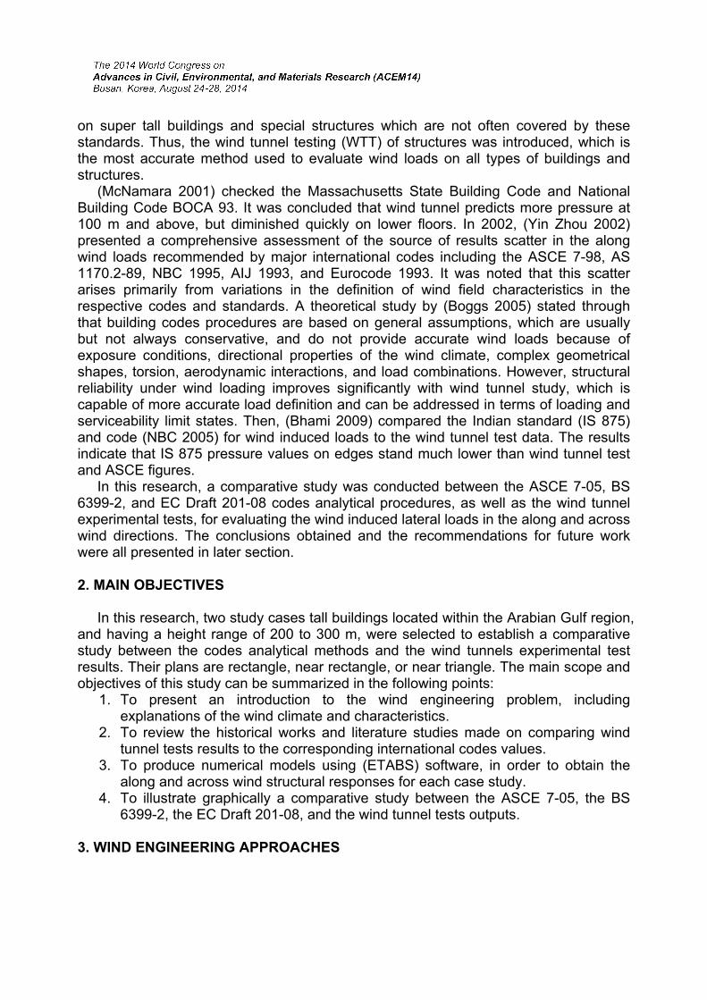
P = 0.85 × [∑(Pfront cosθ) – ∑(Prear cosθ)] × (1 + Cr) (6) The overall load on a building of arbitrary shape may be represented by the cases shown in Fig. 1 where the loaded area is taken as the smallest enclosed rectangle (BSI 1997).
Fig.1 General Case for arbitrary shaped building
3.3. ECP-2008 The method introduced by ECP-08 for calculating wind loads on buildings and structures is as follows: For high rise buildings the wind total force is determined directly from:
F = Cf k q A (7)
Where: (A) is the area subjected to wind. (Cf) is the summation of external coefficients on the windward and leeward faces, the wind exposure height factor (k) is determined from tables in (EC Draft 201-08 2008), and (q) the wind direct pressure is determined from Eq. 8.
q = 0.5 ρ V2 Ct Cs (8)
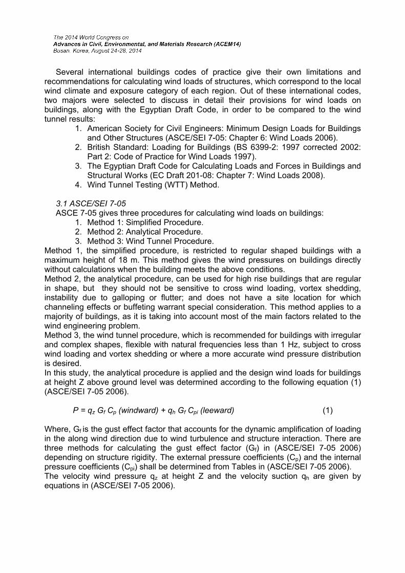
Whereas V is the wind 3 second gust speed at 10 m above the ground for a return period of 50 years from the available wind climate data is determined, taking the air density in Eq. (8) as 1.25 kg/m3, the terrain topographic factor (Ct) is determined from (EC Draft 201-08 2008). The structural factor (Cs) accounts for the dynamic effect of both wind and structure, it is corresponding to the gust factor of ASCE 7-05. 3.4. Wind Tunnel Testing (WTT) Method. The wind tunnel testing (WTT), which is the most reliable technique to expect wind loads on all types of structures. It is valid for complex shapes, irregular structures, and all buildings heights. Finally it takes into account effect of terrains and surroundings as illustrated in Fig. 2 (Davenport 2007). In wind tunnel tests, structures and surrounding buildings and features are converted from full scale into model scale based on consistent length, time, and velocity scales, in order to produce the correct full scale
aerodynamic pressure coefficients. Fig. 2 is schematic of boundary layer wind tunnels (BLWT) model. The model is mounted on a turntable to allow measurement of pressures for any wind direction, typically conducted for 36 wind directions at 10° intervals. Wind tunnel tests typically offer the following important benefits Simiu (2009):
1. Provides accurate distribution of wind loads on structures, by determining the impact of the surroundings. 2. Provides predictions of wind induced building motions, accelerations, and torsion velocities. 3. Pretest estimate of cladding pressures to develop design of structure lateral loads resisting system. 4. Provides an assessment of expected pedestrian wind comfort criteria. 5. The overall design wind load is generally, but not always, lowers than code values, taking into account wind directions and surroundings effects.
Fig. 2 Schematic and internal view of wind tunnel test 4. ETABS PROGRAM ANALYSIS TECHNIQUES (ETABManE.htm) offers the widest assortment of analysis and design tools, including; multi-storey buildings, buildings with steel, concrete, composite or joist floor framing, flat and waffle concrete slab buildings, automated wind and seismic loads, multiple response spectrum cases, P-delta analysis, construction sequence loading analysis, multiple linear and nonlinear time history load cases, and much more. Linear static analysis is used to obtain the structural induced responses of the study cases tall buildings under the effect of wind loads, taking into consideration the P-delta effects. However, modal analysis, using Ritz vector technique, is selected to estimate the structural dynamic properties such as mass distribution and participation ratio, overall stiffness, natural frequencies and periods, damping, and mode shapes. It should be noted that this study is concerned with the effect of wind loads in the along and across wind directions, in order to compare the codes analytical values with the wind tunnel experimental results. Generally, all wind tunnels testing produce the results in the three major directions; set of forces in (x) direction, set of forces in (y) direction, and set of torsion moments

about (z) direction, where (x), (y), and (z) are the building three major dimensions. A set of recommended load combinations, typically 24, are provided by the (BLWT) consultant with the simultaneous application of the floor by floor wind loads. These load combinations represent the worst wind loading scenarios and are produced through consideration of structural responses to various wind directions, modal coupling, correlation of wind gusts, and the directionality of strong winds in the local wind climate. 6. CASE-STUDY Five study cases were studied; two of them will be presented here: The Rolex tower in Dubai and the Lamar Tower in Jeddah. The Rolex tower is 250 meter height, rectangle shape plan (Fig. 3 and 4).
Fig. 3 Typical floor plans for levels (4-16) for Rolex Tower
Fig. 4. Rolex Tower (ETABS) modal analysis

The next case study is Lamar tower in Jeddah with 295 meter height and its plan is near triangle (Fig. 5 and 6).
Fig. 5 Floor plan at L15 for Lamar Tower-1
Fig. 6 Lamar Tower-1 (ETABS) modal analysis

6. PARAMETERS OF CASE STUDIES 6.1 Fixed Parameters
1. Analysis Method: Linear static analysis is used. 2. Main Wind Force Resisting System (MWFRS): Reinforced concrete dual system is used. 3. Section Properties: Gross section properties for strength design and cracked section properties for serviceability checks are used (ACI 318R-05). 4. Diaphragm Type: Rigid diaphragm is used.
6.2 Variable Parameters All buildings are Located within Arabian Gulf region. They are either residential,
hotel, or office building. Number of stories is in range of 50 – 85 stories. Building heights are in the range of
220 – 300 m. Plans are rectangle, near rectangle, or near triangle. Height to width aspect ratio is
in range of 1:4 – 1:8. Natural frequencies are in the range of 0.125 – 0.200 Hz and corresponding
periods are from 5 – 8 seconds. Basic wind speed to ASCE and ECP codes is in range of 35 – 45 m/s, and to BS is
in range of 20 – 30 m/s.
7. RESULTS AND DISCUSSIONS A parametric study using graphical representation is performed on each of the case study buildings, in order to illustrate the relation between codes analytical values and wind tunnel experimental test results, for wind loads in the along wind and across wind directions expressed in terms of the followings: Stories forces, stories shears, overturning moments, lateral displacements, and inter story drifts between floors (ASCE Task Committee 1988). Stories forces are the direct impact of wind load on each level, which depend on the elevation, height, and width of that level, as well as the applied wind pressure. It requires relatively stiff diaphragm to distribute the story force between the available vertical elements of the (MWFRS). Stories shears are the accumulative effect of stories forces over the height of building; or the summation of stories forces for all stories above the studied level. Overturning moments result from multiplying stories forces by the corresponding elevations above ground level, it should be noted that both the stories shears and moments are minimum at the building top level and maximum at the base. Lateral displacements are the horizontal movements of floors due to lateral wind loads, whereas the inter story drifts are the relative lateral displacements between two successive floors divided by the story height (Stafford 1991). Figs. 7-11 illustrates structural responses in the along wind directions of the first case study building; Rolex Tower. The Rolex case study shows almost similar results for all values except for the EC Draft 201-08, which always gave conservative values when compared to ASCE 7-05, BS 6399-2, or wind tunnel. Codes values for stories shears are almost linear, whereas the wind tunnel results are somehow curved. The wind
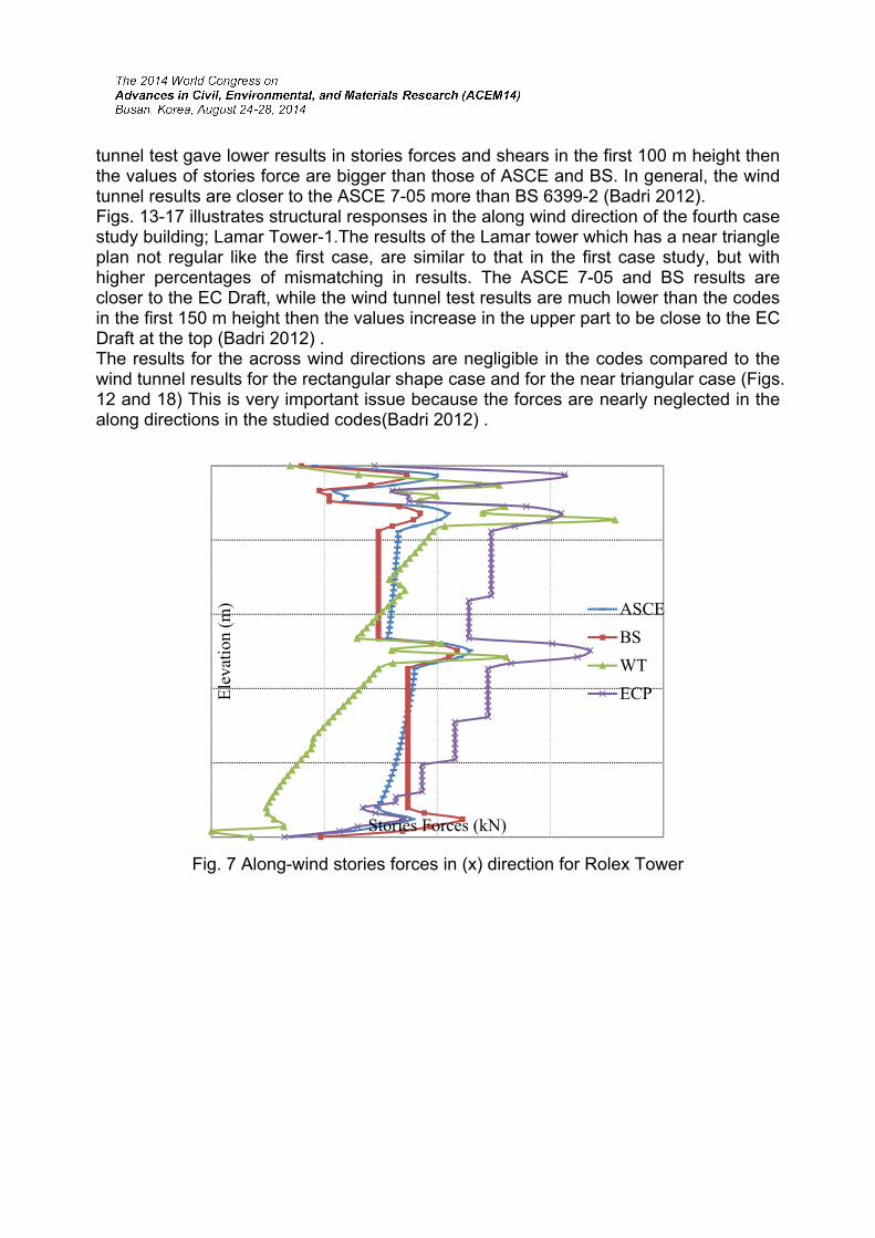
tunnel test gave lower results in stories forces and shears in the first 100 m height then the values of stories force are bigger than those of ASCE and BS. In general, the wind tunnel results are closer to the ASCE 7-05 more than BS 6399-2 (Badri 2012). Figs. 13-17 illustrates structural responses in the along wind direction of the fourth case study building; Lamar Tower-1.The results of the Lamar tower which has a near triangle plan not regular like the first case, are similar to that in the first case study, but with higher percentages of mismatching in results. The ASCE 7-05 and BS results are closer to the EC Draft, while the wind tunnel test results are much lower than the codes in the first 150 m height then the values increase in the upper part to be close to the EC Draft at the top (Badri 2012) . The results for the across wind directions are negligible in the codes compared to the wind tunnel results for the rectangular shape case and for the near triangular case (Figs. 12 and 18) This is very important issue because the forces are nearly neglected in the along directions in the studied codes(Badri 2012) .
Fig. 7 Along-wind stories forces in (x) direction for Rolex Tower
Ele
vati
on (
m)
Stories Forces (kN)
ASCE
BS
WT
ECP
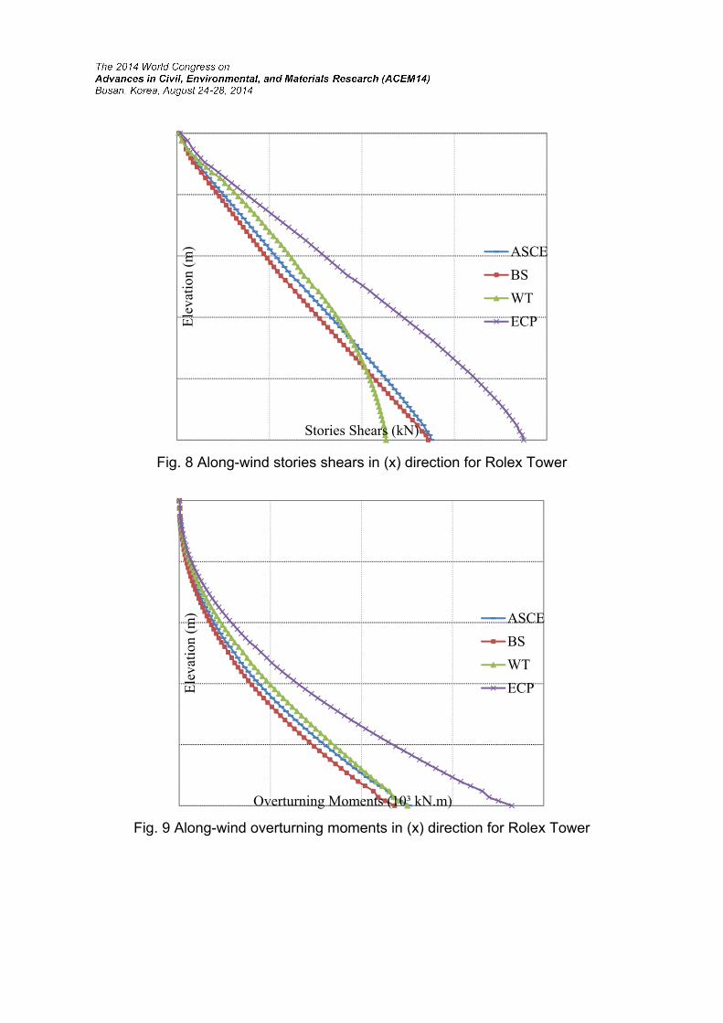
Fig. 8 Along-wind stories shears in (x) direction for Rolex Tower
Fig. 9 Along-wind overturning moments in (x) direction for Rolex Tower
Ele
vati
on (
m)
Stories Shears (kN)
ASCE
BS
WT
ECP
Ele
vati
on (
m)
Overturning Moments (10³ kN.m)
ASCE
BS
WT
ECP

Fig.10 Along-wind lateral displacements in (x) direction for Rolex Tower
Fig. 11 Along-wind stories drifts in (x) direction for Rolex Tower
Ele
vati
on (
m)
Lateral Displacements (mm)
ASCE
BS
WT
ECP
Ele
vati
on (
m)
Stories Drifts (10ˉ³)
ASCE
BS
WT
ECP

Fig.12 Across-wind stories shears in (x) direction for Rolex Tower
Fig. 13 Along-wind stories forces in (x) direction for Lamar Tower-1
Ele
vati
on (
m)
Stories Shears (kN)
ASCE
BS
WT
EC
Ele
vati
on (
m)
Stories Forces (kN)
ASCE
BS
WT
ECP
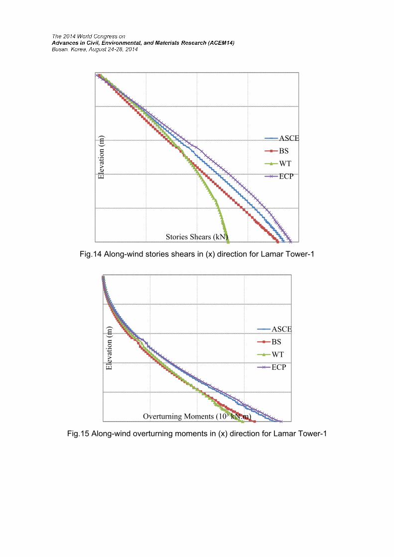
Fig.14 Along-wind stories shears in (x) direction for Lamar Tower-1
Fig.15 Along-wind overturning moments in (x) direction for Lamar Tower-1
Ele
vati
on (
m)
Stories Shears (kN)
ASCE
BS
WT
ECP
Ele
vati
on (
m)
Overturning Moments (10³ kN.m)
ASCE
BS
WT
ECP

Fig. 16 Along-wind lateral displacements in (x) direction for Lamar Tower-1
Fig. 17 Along-wind stories drifts in (x) direction for Lamar Tower-1
Ele
vati
on (
m)
Lateral Displacements (mm)
ASCE
BS
WT
ECP
Ele
vati
on (
m)
Stories Drifts (10ˉ³)
ASCE
BS
WT
ECP

Fig. 18 Across-wind stories shears in (x) direction for Lamar Tower-1
11. CONCLUSIONS The following conclusions are based on the results obtained in this study:
1. In general, all the ASCE 7-05, BS 6399-2, and EC Draft 201-08 codes underestimate the overall effect of the across wind loading on tall buildings, by assuming it to have two equal side suctions on buildings envelopes. However, wind tunnel tests account for this effect correctly, and produce across wind load values much higher than the corresponding codes results. 2. Buildings shape in plan and elevation has major influence on the degree of results agreement between the codes and wind tunnel tests outputs. Rectangular buildings produce the most similar results between codes and tests, whereas other buildings shapes produce conservative codes values for along wind direction when compared to tests results, depending on the degree of building shape irregularity in plan or elevation. 3. The overall design wind loads obtained from wind tunnels are generally lower than that estimated by codes analytical procedures, which could have positive impact on the cost saving for tall buildings. At the same time, wind tunnel tests take into account the effects of surroundings, wind directions, and masses distribution, which are not accurately captured by corresponding codes and
Ele
vati
on (
m)
Stories Shears (kN)
ASCE
BS
WT
EC

standards, making it the most accurate method for evaluating wind loads on all types of buildings and structures. 4. The EC Draft 201-08 gives conservative wind loads and structural responses when compared to the ASCE 7-05, BS 6399-2, and to the wind tunnel test results for flexible tall buildings. On the other side, the ASCE 7-05 code gives results closer to wind tunnels outputs more than the BS 6399-2 or EC Draft 201-08 codes.
5. All the ASCE 7-05, BS 6399-2, and EC Draft 201-08 codes show almost linear distribution of shear forces with the height above ground, whereas the wind tunnel tests results are somehow curved, this allows for a reduced overall effect of wind tunnel loads when compared to these codes values.
Some recommendations could be drawn from this research:
1. Figures and charts investigated in the parametric study of this research can be used to facilitate the preliminary prediction of along and across wind loads on flexible tall buildings 2. Buildings of height range 200 – 300 m, number of stories 50 – 90 stories, and height to width or depth aspect ratios 1:4 – 1:8, are only considered in this study; other buildings ranges are required to be tested for the same criteria. 3. Only the along and across winds are considered in this research, the torsion effects of wind loads on tall buildings should be tested
REFERENCES ASCE 7-05 (2006), “Minimum Design Loads for Buildings and Other Structures”,
STANDARD, American Society of Civil Engineers, Reston, VA. ASCE Task Committee on Drift Control of Steel Building Structures (1988), “Wind drift
design of steel-framed buildings”: state of the art." J. Struct. Eng., Vol.114(9), 2085-2108.
Badri, A. A. (2012), M.Sc. , Thesis “Study of wind tunnel test results of high-rise buildings compared to international and Egyptian design codes”, Faculty of Engineering, Cairo University.
Bhami Mohammed, Cini, C. and Suresh Kumar, K. (2009), “Wind Loads: Where does our code of practice stand”, Proceedings of the Fifth National Conference on Wind Engineering, Surat, India.
Boggs, D., and Lepage A. (2006). “Wind Tunnel Methods”, SP-240 CD Performance-Based Design of Concrete Buildings for Wind Loads. Special Publication sponsored by ACI Committee 375, American Concrete Institute, Farmington Hills, MI., pp. 125-142.

BSI (1997). “Loading for buildings, part 2: code of practice for wind loads.” BS 6399-2, British Standards Institute, London.
Building Code Requirements for Structural Concrete and Commentary “ACI 318R-05”, ACI Committee 318 (2005), American Concrete Institute, - Building - 430 pages.
Alan G. Davenport (2007), “Wind Tunnel Testing: a General Outline.” The Boundary Layer Wind Tunnel Laboratory. The University of Western Ontario, Faculty of Engineering Science London, Ontario, Canada N6A 5B9.
EC Draft 201-08 (2008), “Egyptian Draft Code for Calculating Loads and Forces in Buildings and Structural Works”, Cairo, Egypt.
http://www.comp-engineering.com/ETABManE.htm R. J. McNamara (2001), “Practical Solution to Reduce the Wind Induced Response of
Tall Buildings”, Proceedings of the 6th World Congress of the Council on Tall Buildings and Urban Habitat, Council on Tall Buildings and Urban Habitat, Melbourne Organizing Committee, pp. 603-618.
E. Simiu (2009). "Toward A Standard on the Wind Tunnel Method." NIST Technical Note 1655.
Bryan Stafford Smith and Alex Coull (1991), “Tall Building Structures: Analysis and Design”, New York: John Wiley & Sons, Inc.
Yin Zhou, Tracy Kijewski and Ahsan Kareem (2002), "Along-Wind Load Effects on Tall Buildings: Comparative Study of Major International Codes and Standards", Journal of Structural Engineering, ASCE, Vol.128 (6), 788-796.


