Embed Size (px)
Citation preview
English
0476
compact piezo P2K
Installation manual
2 compact piezo P2K - Installation manual
Summary
00.0 Introduction ........................................................................................................................ .....300.1 Introduction ............................................................................................................... .....300.2 Description of the device ............................................................................................ .....300.3 Use ............................................................................................................................. .....400.4 Safety measures ......................................................................................................... .....4
01.0 Identification data .............................................................................................................. .....501.1 Identification data ....................................................................................................... .....501.2 Device identification tag ............................................................................................ .....501.3 Scaler handpiece identification tag ............................................................................. .....6
02.0 Type testing ........................................................................................................................ .....602.1 Type testing ................................................................................................................ .....6
03.0 Delivery............................................................................................................................... .....603.1 Delivery of the device ................................................................................................. .....603.2 Standard tool supply list ............................................................................................ .....6
04.0 Installation.......................................................................................................................... .....804.1 Size of unit .................................................................................................................. .....804.2 Connecting the device ................................................................................................ .....9
05.0 Diagnostics ........................................................................................................................ ...1206.0 Disposal procedures and precautions ............................................................................ ...1307.0 Symbols.............................................................................................................................. ...1308.0 Problem solving................................................................................................................. ...14
08.1 Procedure for sending the device, inserts and accessories for servicing ................... ...1408.2 Rapid problem solving ................................................................................................ ...14
09.0 Technical data .................................................................................................................... ...1609.1 EN 60601-1-2 electromagnetic compatibility .............................................................. ...17
3 compact piezo P2K - Installation manual
00.0 Introduction00.1 Introduction
Read this manual carefully before you begin any operation for installation, use, maintenance or any other handling of the device.Always keep this manual at hand.
Important: In order to avoid injury to persons or damage to property, read the paragraphs on “Safety measures” in this manual very carefully. Depending on the level of seriousness, the safety measures are classified as follows:� DANGER (always referred to injuries to people)� WARNING (referred to possible damage to property)
The purpose of this manual is to inform the operator of all safety measures, instructions for proper use and maintenance of the device.Tampering with the device is not authorized for any reason. If any anomaly is detected, contact Mectron Assistance Centre. Any attempt to tamper with or modify the device by the operator or non authorized personnel will invalidate the guarantee and relieve the Manufacturer of any responsibility in case of injury to people or damage to property. All the information and illustrations have been updated to the date of issue referred to on the last page.MECTRON has undertaken to continuously upgrade its products with possible modifications and accessories. In the case of discrepancies between the descriptions contained in this manual and the components of the device, contact your Retailer or MECTRON’s Post-sale Service.The use of this manual for purposes other than those strictly concerning installation, use and maintenance of the device is strictly forbidden.
00.2 Description of the device
The Compact piezo P2K is the most modern piezoelectric ultrasound scaler which uses ultrasound technology in dentistry. An integrated feedback system controls the power charge and adapts it to the requirements of the operator in just a few hundredths of a second. In this way, in all fields of application such as endo, scaling and perio, the compact piezo offers the best performance for every situation.The Compact piezo P2K can be used together with the Starlight p (optional), a photopolymerizing light for dental composites. The light is connected to the scaler cord. The device automatically recognizes its insertion.
4 compact piezo P2K - Installation manual
00.3 Intended use
With the relative accessories the device can be applied for the following treatments:- endodontia: for reaming ducts;- tartar removal: for removing plaque and tartar from the dental surface;- periodontal therapy for scaling and root-planning without damaging the periodontal tissues;- retrograde micro-surgery for ultrasound treatment of the root apex;- condensation of the amalgam and of the gutta-percha;- removal of bridges and crowns;- polishing of fillings.
00.4 Safety measures
Mectron declines all responsibility for direct or indirect injury to persons or damage to property in the following cases:1 The device is not used for the purpose for which it was designed.2 The device is used not in conformity with the instructions and prescriptions described in this
manual. 3 The electric system to which the device is connected does not conform to the existing laws and
relative prescriptions.4 The assembly, extension, adjustment, modification and repair operations are carried out by
personnel other than Mectron authorized personnel.5 The environmental conditions in which the device is kept and stored do not conform to the
prescriptions indicated in the technical data section6 � DANGER Using non original Mectron inserts: this causes a permanent damage to the
threading of the handpiece thereby prejudicing a correct performance and risking injury to the patient. In this case the manufacturer’s guarantee and the type-approval of the device will no longer be valid!
� DANGER: Qualified and specialized personnel only.This device must be operated exclusively by specialized or specifically trained personnel. Operating the device does not cause any collateral effects if used properly
� DANGER: Use.Only use the device for the purpose for which it was designed (see paragraph “00.3”). Failure to comply to this prescription may cause serious injury to the patient, the operator and damage/faults to the device.
� DANGER:Contraindications.Do not use the ultrasound tartar scaler on patients with cardiac stimulator (Pace-maker) or other electronic implants. This prescription is intended also for the operator.
� DANGER: Cleaning, disinfecting, sterilizing new and repaired products.All new or repaired products are delivered un-sterilized. Before using, all new or repaired products must be cleaned, disinfected and sterilized scrupulously following the instructions in chapter “05.0”.
� DANGER: Infection control.For maximum security of patient and operator, only use clean, disinfected and sterilized accessories. Scrupulously follow the instructions in chapter “05.0”.
5 compact piezo P2K - Installation manual
� DANGER: Only use original Mectron accessories and spares.
� WARNING: Contraindications.Do not scale the tartar on metal or ceramic prosthetic dentures. The ultrasound vibrations could loosen the dentures.
� DANGER: Contraindications.Do not scale without water irrigation to avoid over heating the insert which can damage the tooth.Scaling without irrigation can be done exclusively with the special “Dry Work” inserts.
� DANGER: Insert wear and breaking.The high frequency vibrations and wear and tear can, in some rare cases, lead to the insert breaking.Deformed or otherwise damaged inserts are susceptible to breaking during use. Broken or worn inserts must never be used.When the nitriding wears off, the insert looses its effectiveness; always check that the insert is not worn. While using, avoid prolonged contact with other metal instruments. Do not use excessive force on the inserts while using.To avoid the patient swallowing a fragment of broken insert, always instruct the patient to breath through the nose during treatment.
� DANGER: Do not use the device in places where there is a risk of explosion.The device must not be operated in the presence of inflammable gases (anaesthetic compounds, oxygen, etc.).
01.0 Identification data01.1 Identification data
An exact description of the model and indication of the serial number of the device will make it easier for our Post Sales Service to give prompt and effective answers to the purchaser’s queries.Always refer to this data when contacting Mectron’s Technical Assistance centre.
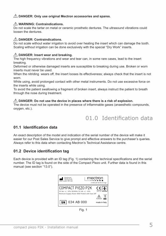
01.2 Device identification tag
Each device is provided with an ID tag (Fig. 1) containing the technical specifications and the serial number. The ID tag is found on the side of the Compact Piezo unit. Further data is found in this manual (see section “13.0”).
Fig. 1
24 Vac +/- 10% 50/60Hz 32 Vdc +/- 10%Minimum Supply Power 40W Protect with fuse 2AT
034 AB 000
Manufacturer Mectron S.p.A. Via Loreto 15/a16042 Carasco -GE- Italy
0476
made in Italy
COMPACT PIEZO P2K
6 compact piezo P2K - Installation manual
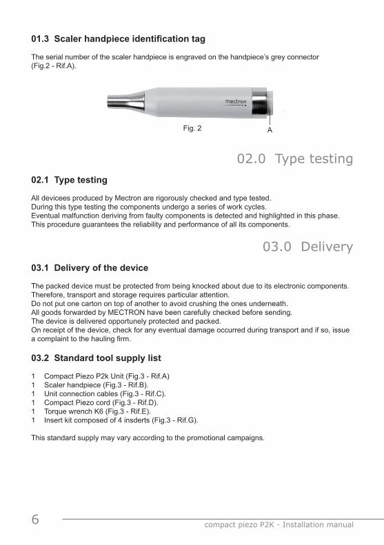
AFig. 2
01.3 Scaler handpiece identification tag The serial number of the scaler handpiece is engraved on the handpiece’s grey connector (Fig.2 - Rif.A).
02.0 Type testing02.1 Type testing
All devicees produced by Mectron are rigorously checked and type tested.During this type testing the components undergo a series of work cycles.Eventual malfunction deriving from faulty components is detected and highlighted in this phase.This procedure guarantees the reliability and performance of all its components.
03.0 Delivery03.1 Delivery of the device
The packed device must be protected from being knocked about due to its electronic components. Therefore, transport and storage requires particular attention.Do not put one carton on top of another to avoid crushing the ones underneath. All goods forwarded by MECTRON have been carefully checked before sending.The device is delivered opportunely protected and packed.On receipt of the device, check for any eventual damage occurred during transport and if so, issue a complaint to the hauling firm.
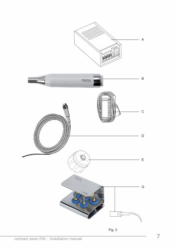
03.2 Standard tool supply list
1 Compact Piezo P2k Unit (Fig.3 - Rif.A)1 Scaler handpiece (Fig.3 - Rif.B).1 Unit connection cables (Fig.3 - Rif.C).1 Compact Piezo cord (Fig.3 - Rif.D).1 Torque wrench K6 (Fig.3 - Rif.E).1 Insert kit composed of 4 insderts (Fig.3 - Rif.G).
This standard supply may vary according to the promotional campaigns.
7 compact piezo P2K - Installation manual
G
B
E
Fig. 3
D
C
A
8 compact piezo P2K - Installation manual
04.0 InstallationThis device does not have any particular positioning indications.
� WARNING: Place the device where it is safe from being knocked or sprayed with water. When installing make sure there is an adequate space around the device, particularly in correspondence of the air vents.
� WARNING: The voltage of the electric power supply to which the device will be connected must be compatible with the indications on the ID tag and the chosen connection diagram.
� WARNING: For a correct power supply use a double isolation transformer.
� WARNING: Do not for any reason invert the position on the connector (Fig. 8) of the red wire and black wire of the scaler handpiece .
� WARNING: Do not wire the red and black wires of the scaler handpiece cord with other wires.
� WARNING: If lengthy connections are needed for the power supply, only use adequate section wires, for example 1,5 mm2.
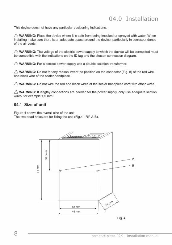
04.1 Size of unit
Figure 4 shows the overall size of the unit. The two dead holes are for fixing the unit (Fig.4 - Rif. A-B).
Fig. 4
42 mm
71 m
m
36.5
mm
34 mm
46 mm
A
B
9 compact piezo P2K - Installation manual
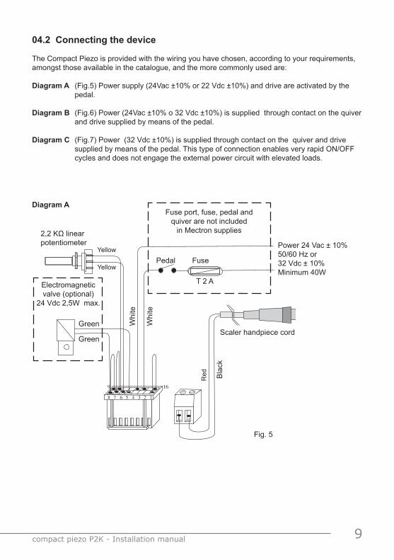
04.2 Connecting the device
The Compact Piezo is provided with the wiring you have chosen, according to your requirements, amongst those available in the catalogue, and the more commonly used are:
Diagram A (Fig.5) Power supply (24Vac ±10% or 22 Vdc ±10%) and drive are activated by the pedal.
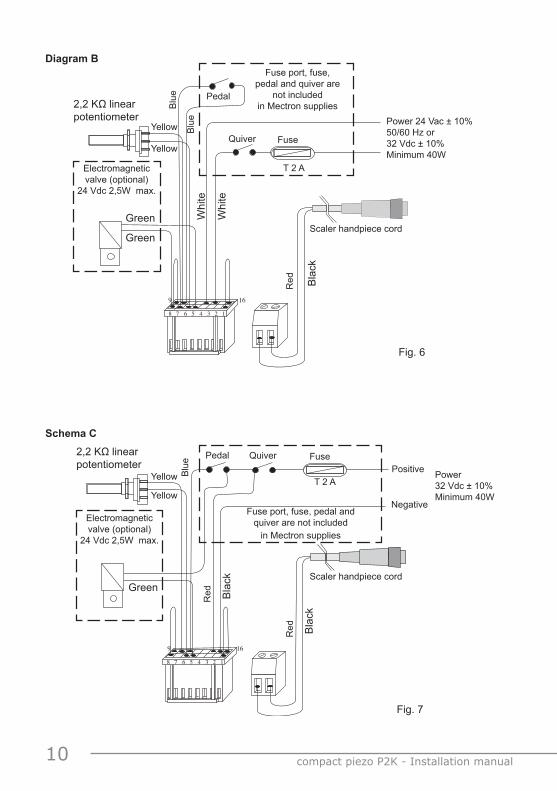
Diagram B (Fig.6) Power (24Vac ±10% o 32 Vdc ±10%) is supplied through contact on the quiver and drive supplied by means of the pedal.
Diagram C (Fig.7) Power (32 Vdc ±10%) is supplied through contact on the quiver and drive supplied by means of the pedal. This type of connection enables very rapid ON/OFF cycles and does not engage the external power circuit with elevated loads.
9 16
8 7 6 5 4 3 2 1
Fuse port, fuse, pedal and quiver are not included
in Mectron supplies
Pedal
T 2 A
FuseYellow
Yellow
2,2 KΩ linear potentiometer
Bla
ck
Red
Green
Green
Whi
te
Whi
te
Electromagnetic valve (optional)
24 Vdc 2,5W max.
Scaler handpiece cord
Power 24 Vac ± 10% 50/60 Hz or 32 Vdc ± 10% Minimum 40W
Fig. 5
Diagram A
10 compact piezo P2K - Installation manual
9 16
8 7 6 5 4 3 2 1
Fuse port, fuse, pedal and quiver are
not included in Mectron supplies
Quiver
T 2 A
FuseYellow
Yellow
2,2 KΩ linear potentiometer
Bla
ck
Red
Green
Green
Whi
te
Whi
te
Electromagnetic valve (optional)
24 Vdc 2,5W max.
Scaler handpiece cord
Power 24 Vac ± 10% 50/60 Hz or 32 Vdc ± 10% Minimum 40W
Pedal
Blu
e
Blu
e
Fig. 6
Diagram B
9 16
8 7 6 5 4 3 2 1
Fuse port, fuse, pedal and quiver are not included
in Mectron supplies
Quiver
T 2 A
Fuse
Yellow
Yellow
2,2 KΩ linear potentiometer
Bla
ck
Red
Green
Electromagnetic valve (optional)
24 Vdc 2,5W max.
Scaler handpiece cord
Pedal
Blu
e
Bla
ck
Red
Positive
Negative
Fig. 7
Schema C
Power 32 Vdc ± 10% Minimum 40W
11 compact piezo P2K - Installation manual
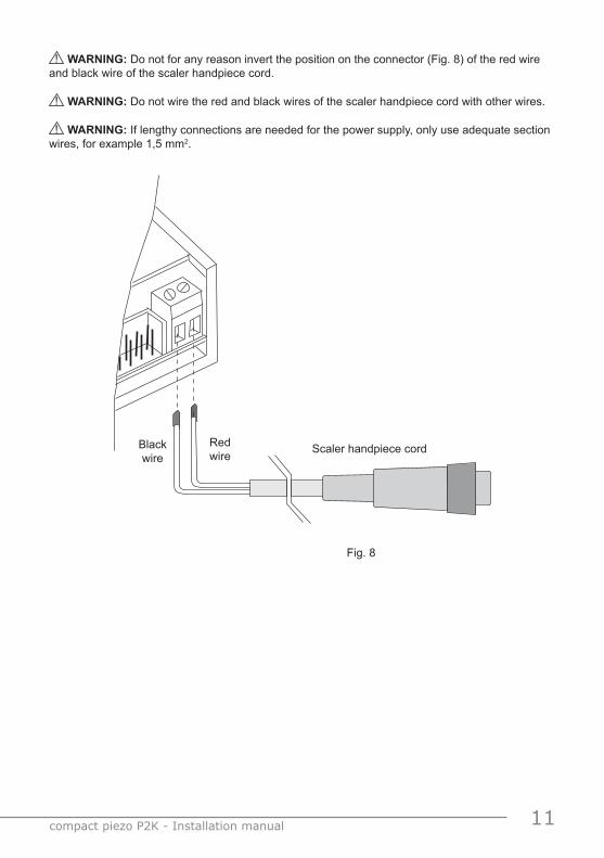
� WARNING: Do not for any reason invert the position on the connector (Fig. 8) of the red wire and black wire of the scaler handpiece cord.
� WARNING: Do not wire the red and black wires of the scaler handpiece cord with other wires.
� WARNING: If lengthy connections are needed for the power supply, only use adequate section wires, for example 1,5 mm2.
Scaler handpiece cordBlack wire
Red wire
Fig. 8
12 compact piezo P2K - Installation manual
05.0 DiagnosticsThe device is provided with an APC, Automatic Protection Circuit, which is enabled when there are anomalies in the function of the components and in the bi-colour (green-red) led diagnostics which indicate when the device is connected to the power line.
Description of diagnostic indicators
Device powered without pedal drive:
Green led on Functioning correctly.
Green and red led flashing in alternation Incorrect installation: - Potentiometer not connected.
Green and red led on Indicates that during the previous work cycle the general protection has been activated.
Green led on, red led flashing Indicates that during the previous work cycle the failed syntonic scan protection has
been activated.
Device powered with pedal drive:
Green led on Correct function.
Green/red led on Current limiter functioning
Green and red led flashing in alternation Incorrect installation: - Power supply too low. - Power supply too high. - Potentiometer not connected.
Red led on General protection activated: - Handpiece not connected to the cord. - Syntonic circuit malfunction. - Cord wire interruption. - Handpiece malfunction.
Red flashing led Failed syntonic scan protection activated: - Insert not correctly connected to the handpiece. - Worn, broken or deformed insert. - Handpiece/cord electric contacts are wet
13 compact piezo P2K - Installation manual
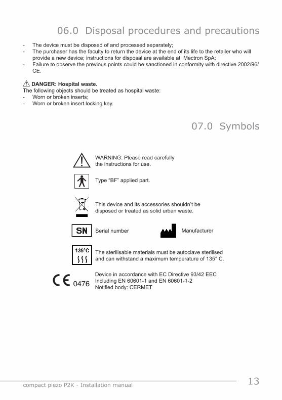
06.0 Disposal procedures and precautions- The device must be disposed of and processed separately;- The purchaser has the faculty to return the device at the end of its life to the retailer who will
provide a new device; instructions for disposal are available at Mectron SpA;- Failure to observe the previous points could be sanctioned in conformity with directive 2002/96/
CE.
� DANGER: Hospital waste.The following objects should be treated as hospital waste:- Worn or broken inserts;- Worn or broken insert locking key.
07.0 Symbols
WARNING: Please read carefully the instructions for use.�Type “BF” applied part.
This device and its accessories shouldn’t be disposed or treated as solid urban waste.
0476Device in accordance with EC Directive 93/42 EECIncluding EN 60601-1 and EN 60601-1-2Notified body: CERMET
The sterilisable materials must be autoclave sterilised and can withstand a maximum temperature of 135° C.
Serial number Manufacturer
14 compact piezo P2K - Installation manual
08.0 Problem solving08.1 Procedure for sending the device, inserts and accessories for
servicing
When sending the device, inserts and accessories for servicing at Mectron authorized centers, customers are kindly invited to respect the following norms:
1 Clean the device, inserts and accessories following the instructions in chapter “05.0 Cleaning, disinfecting and sterilizing”;
2 Sterilize the parts which can be sterilized following the instructions in chapter l“05.0 Cleaning, disinfecting and sterilizing”:
- Handpiece; - Insert/s; - Torque wrench.3 Leave the sterilized components in the disposable bag which states the contents is sterilized;4 If the device is still under guarantee, attach a photocopy of the purchase document;5 When sending, if possible use the original packing or pack adequately to avoid damage during
transport.
The above mentioned requests (points 1 and 2) conform to the compulsory requisites for health and safety on the work place as provided for in Leg. Decr. 626/9 and 81/08 and subsequent amendments, of the Italian C.C.If the customer does not comply with the requirements as in Points 1 and 2, Mectron reserves the right to charge cleaning and sterilizing costs or refuse the goods received for servicing in non conforming conditions.
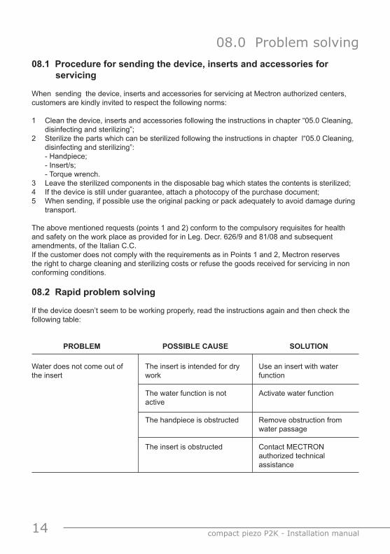
08.2 Rapid problem solving
If the device doesn’t seem to be working properly, read the instructions again and then check the following table:
PROBLEM POSSIBLE CAUSE SOLUTION
Water does not come out of the insert
The insert is intended for dry work
The water function is not active
The handpiece is obstructed
The insert is obstructed
Use an insert with water function
Activate water function
Remove obstruction from water passage
Contact MECTRON authorized technical assistance
15 compact piezo P2K - Installation manual
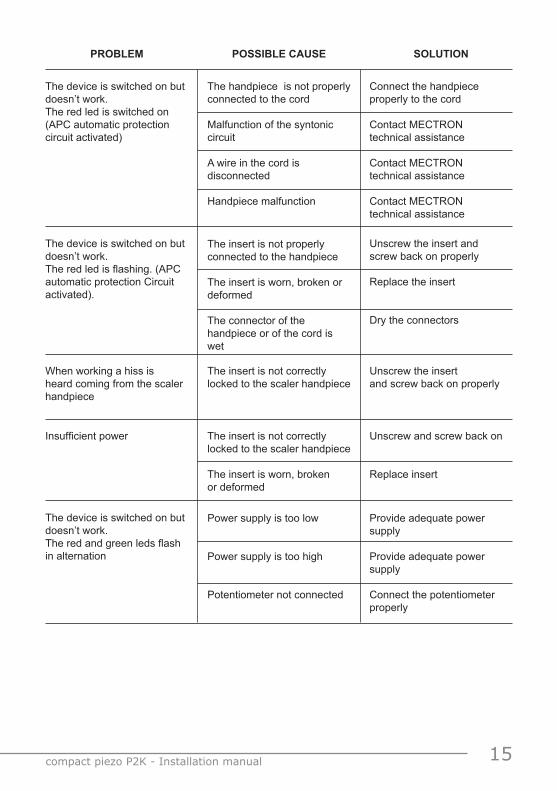
The device is switched on but doesn’t work. The red led is switched on (APC automatic protection circuit activated)
The handpiece is not properly connected to the cord
Malfunction of the syntonic circuit
A wire in the cord is disconnected
Handpiece malfunction
Connect the handpiece properly to the cord
Contact MECTRON technical assistance
Contact MECTRON technical assistance
Contact MECTRON technical assistance
When working a hiss is heard coming from the scaler handpiece
The insert is not correctly locked to the scaler handpiece
Unscrew the insert and screw back on properly
Insufficient power The insert is not correctly locked to the scaler handpiece
The insert is worn, broken or deformed
Unscrew and screw back on
Replace insert
PROBLEM POSSIBLE CAUSE SOLUTION
The device is switched on but doesn’t work. The red led is flashing. (APC automatic protection Circuit activated).
The insert is not properly connected to the handpiece
The insert is worn, broken or deformed
The connector of the handpiece or of the cord is wet
Unscrew the insert and screw back on properly
Replace the insert
Dry the connectors
The device is switched on but doesn’t work. The red and green leds flash in alternation
Power supply is too low
Power supply is too high
Potentiometer not connected
Provide adequate power supply
Provide adequate power supply
Connect the potentiometer properly
16 compact piezo P2K - Installation manual
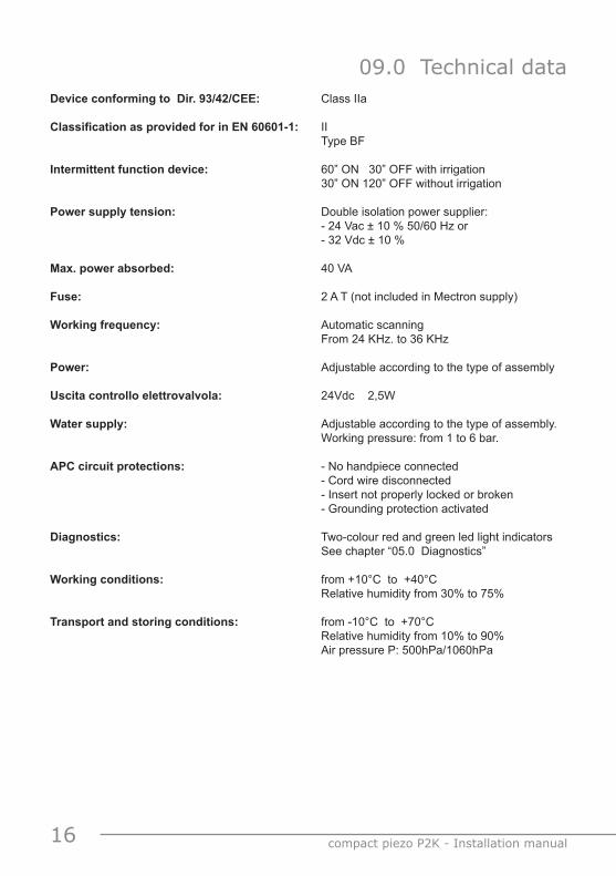
09.0 Technical dataDevice conforming to Dir. 93/42/CEE: Class IIa
Classification as provided for in EN 60601-1: II Type BF Intermittent function device: 60” ON 30” OFF with irrigation 30” ON 120” OFF without irrigation
Power supply tension: Double isolation power supplier: - 24 Vac ± 10 % 50/60 Hz or - 32 Vdc ± 10 %
Max. power absorbed: 40 VA
Fuse: 2 A T (not included in Mectron supply)
Working frequency: Automatic scanning From 24 KHz. to 36 KHz
Power: Adjustable according to the type of assembly
Uscita controllo elettrovalvola: 24Vdc 2,5W
Water supply: Adjustable according to the type of assembly. Working pressure: from 1 to 6 bar.
APC circuit protections: - No handpiece connected - Cord wire disconnected - Insert not properly locked or broken - Grounding protection activated Diagnostics: Two-colour red and green led light indicators See chapter “05.0 Diagnostics”
Working conditions: from +10°C to +40°C Relative humidity from 30% to 75%
Transport and storing conditions: from -10°C to +70°C Relative humidity from 10% to 90% Air pressure P: 500hPa/1060hPa
17 compact piezo P2K - Installation manual
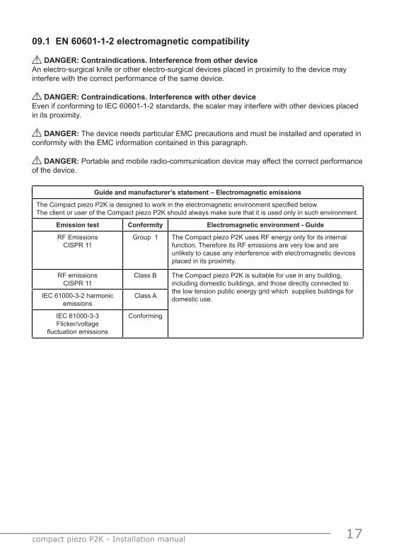
09.1 EN 60601-1-2 electromagnetic compatibility
� DANGER: Contraindications. Interference from other device An electro-surgical knife or other electro-surgical devices placed in proximity to the device may interfere with the correct performance of the same device.
� DANGER: Contraindications. Interference with other deviceEven if conforming to IEC 60601-1-2 standards, the scaler may interfere with other devices placed in its proximity.
� DANGER: The device needs particular EMC precautions and must be installed and operated in conformity with the EMC information contained in this paragraph.
� DANGER: Portable and mobile radio-communication device may effect the correct performance of the device.
Guide and manufacturer’s statement – Electromagnetic emissions
The Compact piezo P2K is designed to work in the electromagnetic environment specified below.The client or user of the Compact piezo P2K should always make sure that it is used only in such environment.
Emission test Conformity Electromagnetic environment - Guide
RF EmissionsCISPR 11
Group 1 The Compact piezo P2K uses RF energy only for its internal function. Therefore its RF emissions are very low and are unlikely to cause any interference with electromagnetic devices placed in its proximity.
RF emissionsCISPR 11
Class B The Compact piezo P2K is suitable for use in any building, including domestic buildings, and those directly connected to the low tension public energy grid which supplies buildings for domestic use.IEC 61000-3-2 harmonic
emissionsClass A
IEC 61000-3-3 Flicker/voltage
fluctuation emissions
Conforming
18 compact piezo P2K - Installation manual
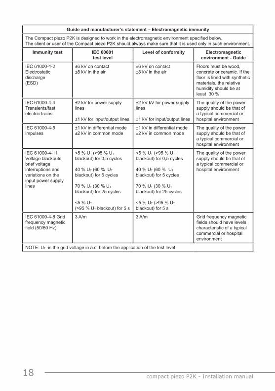
Guide and manufacturer’s statement – Electromagnetic immunity
The Compact piezo P2K is designed to work in the electromagnetic environment specified below.The client or user of the Compact piezo P2K should always make sure that it is used only in such environment.
Immunity test IEC 60601test level
Level of conformity Electromagneticenvironment - Guide
IEC 61000-4-2 Electrostatic discharge(ESD)
±6 kV on contact±8 kV in the air
±6 kV on contact±8 kV in the air
Floors must be wood, concrete or ceramic. If the floor is lined with synthetic materials, the relative humidity should be at least 30 %
IEC 61000-4-4Transients/fast electric trains
±2 kV for power supply lines
±1 kV for input/output lines
±2 kV kV for power supply lines
±1 kV for input/output lines
The quality of the power supply should be that of a typical commercial or hospital environment
IEC 61000-4-5impulses
±1 kV in differential mode±2 kV in common mode
±1 kV in differential mode ±2 kV in common mode
The quality of the power supply should be that of a typical commercial or hospital environment
IEC 61000-4-11 Voltage blackouts, brief voltage interruptions and variations on the input power supply lines
<5 % UT (>95 % UT blackout) for 0,5 cycles
40 % UT (60 % UT blackout) for 5 cycles
70 % UT (30 % UT blackout) for 25 cycles
<5 % UT
(>95 % UT blackout) for 5 s
<5 % UT (>95 % UT blackout) for 0,5 cycles
40 % UT (60 % UT blackout) for 5 cycles
70 % UT (30 % UT blackout) for 25 cycles
<5 % UT (>95 % UT blackout) for 5 s
The quality of the power supply should be that of a typical commercial or hospital environment
IEC 61000-4-8 Grid frequency magnetic field (50/60 Hz)
3 A/m 3 A/m Grid frequency magnetic fields should have levels characteristic of a typical commercial or hospital environment
NOTE: UT is the grid voltage in a.c. before the application of the test level
19 compact piezo P2K - Installation manual
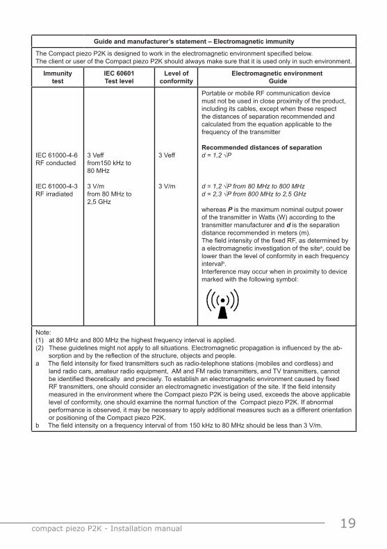
Guide and manufacturer’s statement – Electromagnetic immunity
The Compact piezo P2K is designed to work in the electromagnetic environment specified below.The client or user of the Compact piezo P2K should always make sure that it is used only in such environment.
Immunity test
IEC 60601Test level
Level of conformity
Electromagnetic environment Guide
IEC 61000-4-6RF conducted
IEC 61000-4-3RF irradiated
3 Vefffrom150 kHz to 80 MHz
3 V/mfrom 80 MHz to 2,5 GHz
3 Veff
3 V/m
Portable or mobile RF communication device must not be used in close proximity of the product, including its cables, except when these respect the distances of separation recommended and calculated from the equation applicable to the frequency of the transmitter
Recommended distances of separationd = 1,2 √P
d = 1,2 √P from 80 MHz to 800 MHzd = 2,3 √P from 800 MHz to 2,5 GHz
whereas P is the maximum nominal output power of the transmitter in Watts (W) according to the transmitter manufacturer and d is the separation distance recommended in meters (m).The field intensity of the fixed RF, as determined by a electromagnetic investigation of the sitea, could be lower than the level of conformity in each frequency intervalb.Interference may occur when in proximity to device marked with the following symbol:
Note:(1) at 80 MHz and 800 MHz the highest frequency interval is applied.(2) These guidelines might not apply to all situations. Electromagnetic propagation is influenced by the ab-
sorption and by the reflection of the structure, objects and people.a The field intensity for fixed transmitters such as radio-telephone stations (mobiles and cordless) and
land radio cars, amateur radio equipment, AM and FM radio transmitters, and TV transmitters, cannot be identified theoretically and precisely. To establish an electromagnetic environment caused by fixed RF transmitters, one should consider an electromagnetic investigation of the site. If the field intensity measured in the environment where the Compact piezo P2K is being used, exceeds the above applicable level of conformity, one should examine the normal function of the Compact piezo P2K. If abnormal performance is observed, it may be necessary to apply additional measures such as a different orientation or positioning of the Compact piezo P2K.
b The field intensity on a frequency interval of from 150 kHz to 80 MHz should be less than 3 V/m.
20 compact piezo P2K - Installation manual
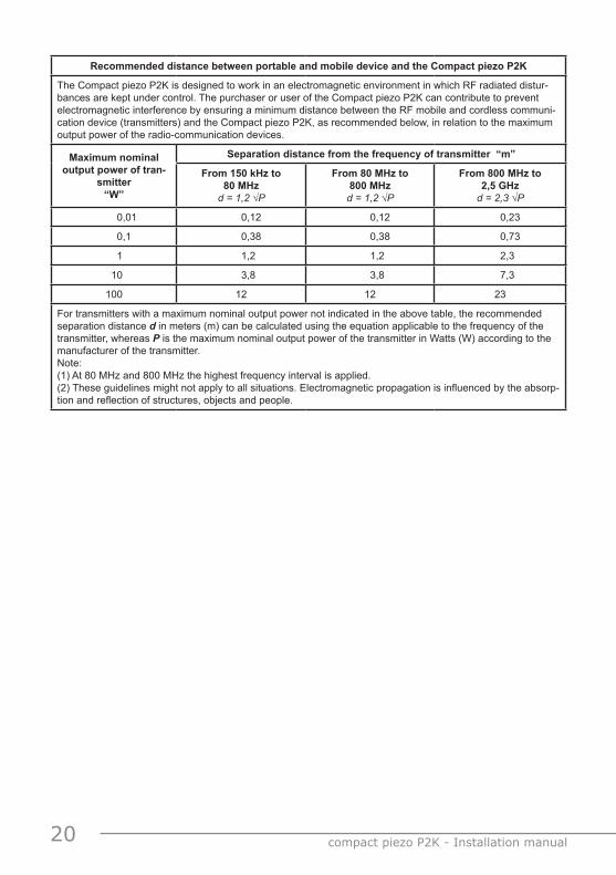
Recommended distance between portable and mobile device and the Compact piezo P2K
The Compact piezo P2K is designed to work in an electromagnetic environment in which RF radiated distur-bances are kept under control. The purchaser or user of the Compact piezo P2K can contribute to prevent electromagnetic interference by ensuring a minimum distance between the RF mobile and cordless communi-cation device (transmitters) and the Compact piezo P2K, as recommended below, in relation to the maximum output power of the radio-communication devices.
Maximum nominal output power of tran-
smitter“W”
Separation distance from the frequency of transmitter “m”
From 150 kHz to 80 MHz
d = 1,2 √P
From 80 MHz to 800 MHz d = 1,2 √P
From 800 MHz to 2,5 GHz
d = 2,3 √P
0,01 0,12 0,12 0,23
0,1 0,38 0,38 0,73
1 1,2 1,2 2,3
10 3,8 3,8 7,3
100 12 12 23
For transmitters with a maximum nominal output power not indicated in the above table, the recommended separation distance d in meters (m) can be calculated using the equation applicable to the frequency of the transmitter, whereas P is the maximum nominal output power of the transmitter in Watts (W) according to the manufacturer of the transmitter.Note:(1) At 80 MHz and 800 MHz the highest frequency interval is applied.(2) These guidelines might not apply to all situations. Electromagnetic propagation is influenced by the absorp-tion and reflection of structures, objects and people.

21 compact piezo P2K - Installation manual

22 compact piezo P2K - Installation manual

23 compact piezo P2K - Installation manual
Rivenditore - Reseller - Wiederverkäufer - Revendeur - Revendedor
inst
.com
pact
pie
zo P
2K V
. EN
Re
v. 0
8 de
l 19-
02-2
010manufacturer:
Mectron S.p.A.Via Loreto 15/A16042 Carasco (Ge) ItalyTel. +39 0185 35361Fax +39 0185 351374www.mectron.come-mail: [email protected]


![[DESIGN] Piezo-Piezo to Pie](https://img.dokumen.tips/doc/110x75/5571f8bb49795991698df909/design-piezo-piezo-to-pie.jpg)