Embed Size (px)
Citation preview
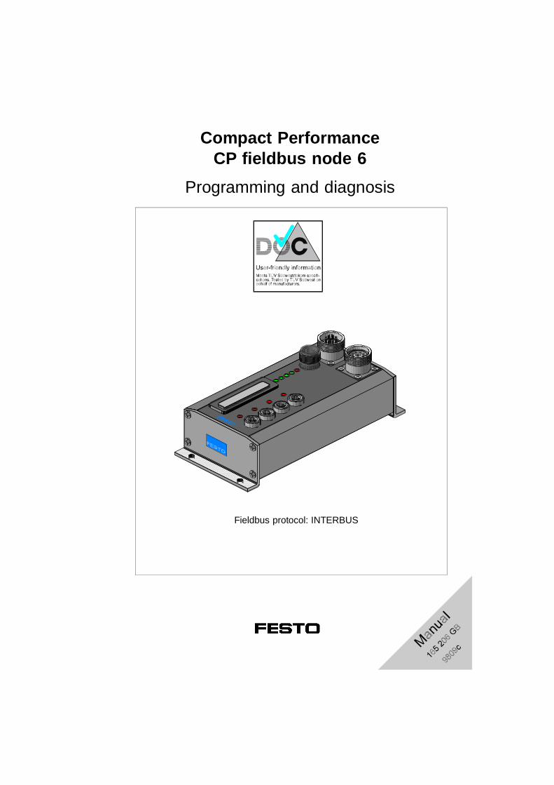
Compact PerformanceCP fieldbus node 6
Programming and diagnosis
Fieldbus protocol: INTERBUS
Author: H.-J. Drung, E. KlotzEditors: H.-J. Drung, M. HolderTranslation: D.Smith Layout: Festo, Dept. KI-TDType setting: PV-IDM
Edition: 9809c
(Festo AG & Co., 73726 Esslingen, Federal Republic of Germany, 1998)
The copying, distribution and utilization of this docu-ment as well as the communication of its contents toothers without expressed authorization is prohibited. Of-fenders will be held liable for the payment of damages.All rights reserved, in particular the right to carry outpatent, utility model or ornamental design registrations. P
rinte
d on
100
% r
ecyc
led
pape
rContents and general safety instructions
CP FB6-E 9809c I

Order no.: 165 206Title: ManualDesignation: P.BE CP-FB6-E-GB
Contents and general safety instructions
II CP FB6-E 9809c
Contents
Designated use. . . . . . . . . . . . . . . . . . . . . . . . . . . . . . . . . . . . . . . . . . . . . . VTarget group . . . . . . . . . . . . . . . . . . . . . . . . . . . . . . . . . . . . . . . . . . . . . . . . VInformation on this manual . . . . . . . . . . . . . . . . . . . . . . . . . . . . . . . . . . . . . VImportant user instructions . . . . . . . . . . . . . . . . . . . . . . . . . . . . . . . . . . . . VI
1. Installation
1.1 General instructions . . . . . . . . . . . . . . . . . . . . . . . . . . . . . . . . . . . 1-31.2 Setting the DIL switches . . . . . . . . . . . . . . . . . . . . . . . . . . . . . . . 1-41.3 Connecting the INTERBUS interface. . . . . . . . . . . . . . . . . . . . . . 1-61.3.1 Floating structure . . . . . . . . . . . . . . . . . . . . . . . . . . . . . . . . . . . . 1-81.3.2 Non-floating structure . . . . . . . . . . . . . . . . . . . . . . . . . . . . . . . . . 1-91.4 Connection to the remote bus . . . . . . . . . . . . . . . . . . . . . . . . . . 1-101.4.1 Floating remote bus . . . . . . . . . . . . . . . . . . . . . . . . . . . . . . . . . 1-101.4.2 Non-floating remote bus . . . . . . . . . . . . . . . . . . . . . . . . . . . . . . . 1-111.5 Connection to the installation remote bus . . . . . . . . . . . . . . . . . 1-141.5.1 Non-floating installation remote bus. . . . . . . . . . . . . . . . . . . . . 1-141.6 Connecting CP modules . . . . . . . . . . . . . . . . . . . . . . . . . . . . . . 1-161.7 Connecting the operating voltage . . . . . . . . . . . . . . . . . . . . . . . 1-17
2. Commissioning
2.1 Preparing the CP system for operation on the INTERBUS . . . . . . . . . . . . . . . . . . . . . . . . . . . . . . . . . . . . 2-3
2.1.1 Operating voltage . . . . . . . . . . . . . . . . . . . . . . . . . . . . . . . . . . . . 2-32.1.2 Saving the string assignment . . . . . . . . . . . . . . . . . . . . . . . . . . . 2-32.2 Preparing the INTERBUS interface module . . . . . . . . . . . . . . . . 2-42.2.1 Creating the configuration list . . . . . . . . . . . . . . . . . . . . . . . . . 2-42.2.2 Bus configuration via the CMD software . . . . . . . . . . . . . . . . . . 2-52.2.3 Bus configuration without CMD software. . . . . . . . . . . . . . . . . . 2-122.3 Commissioning the CP system on the INTERBUS . . . . . . . . . . 2-172.4 Configuration . . . . . . . . . . . . . . . . . . . . . . . . . . . . . . . . . . . . . . . 2-192.4.1 Addressing the inputs/outputs . . . . . . . . . . . . . . . . . . . . . . . . . 2-192.4.2 Manufacturer-specific addressing (byte swap). . . . . . . . . . . . . 2-212.4.3 Process data assignment via the CMD software (byte swap). 2-242.4.4 Other instructions . . . . . . . . . . . . . . . . . . . . . . . . . . . . . . . . . . . 2-27
Contents and general safety instructions
CP FB6-E 9809c III
3. Diagnosis
3.1 LED displays on the bus node . . . . . . . . . . . . . . . . . . . . . . . . . . 3-33.1.2 Normal operating status . . . . . . . . . . . . . . . . . . . . . . . . . . . . . . . 3-43.1.3 Diagnosis operating voltage POWER or POWER V . . . . . . . . . 3-53.1.4 Diagnostic bus LEDs . . . . . . . . . . . . . . . . . . . . . . . . . . . . . . . . . 3-63.2 Testing the valves. . . . . . . . . . . . . . . . . . . . . . . . . . . . . . . . . . . . 3-83.3 Diagnosis via INTERBUS. . . . . . . . . . . . . . . . . . . . . . . . . . . . . 3-103.3.1 Diagnostic status register . . . . . . . . . . . . . . . . . . . . . . . . . . . . . 3-103.3.2 Periphery fault (PF) . . . . . . . . . . . . . . . . . . . . . . . . . . . . . . . . . 3-113.4 Reaction to faults in the control system . . . . . . . . . . . . . . . . . 3-12
A. Technical appendix
A.1 Technical specifications of the field bus node CP FB6-E . . . . . A-3A.2 Index . . . . . . . . . . . . . . . . . . . . . . . . . . . . . . . . . . . . . . . . . . . . . . A-5
Contents and general safety instructions
IV CP FB6-E 9809c
Designated use
The CP field bus node CP-FB6-E documented in thismanual is designated exclusively for use as a slave onthe INTERBUS. Festo CP modules can be connectedto the field bus node CP-FB6-E. The specified limitvalues for pressures, temperatures, electrical data, mo-ments, etc. must be observed when additional commer-cially-available components such as sensors and actua-tors are connected.
Please comply also with national and local safety lawsand regulations.
Target group
This manual is directed exclusively at technicians whoare trained in control and automation technology andwho have experience in installing, commissioning, pro-gramming and diagnosing INTERBUS slaves.
Information on this manual
This manual contains specific information on the instal-lation, commissioning, programming and diagnosis ofthe CP field bus node 6 for INTERBUS.
Information on further CP modules can be found in therelevant manual. This is summarized in Fig. 0/1.
Contents and general safety instructions
CP FB6-E 9809c V
Important user instructions
This manual contains instructions on the dangers whichmay occur if the CP system is not used correctly. Theseinstructions are always printed in italics, are framed andalso signalled by a pictogram.
Dangercategories
A distinction is made between the following:
WARNINGThis means that personal injury tor damage to property may occur if these instructions are not observed.
CAUTIONThis means that damage to property may occur if these instructions are not observed.
PLEASE NOTEThis means that this instruction must also be ob-served.
Contents and general safety instructions
VI CP FB6-E 9809c
Pictograms and symbols complement the danger warn-ings and draw attention to the nature and conse-quences of dangers.
Pictograms
The following pictograms are used:
Uncontrolled movements of loose tubing.
Unintentional movements of the connected actuators.
Electrostatically vulnerable components.These will be damaged if you touch the contact sur-faces.
•• This mark indicates activities which can be carriedout in any order.
Text markings
1. Figures indicate activities which must be carried outin the numerical order of the figures.
– Hyphens indicate general activites.
Contents and general safety instructions
CP FB6-E 9809c VII
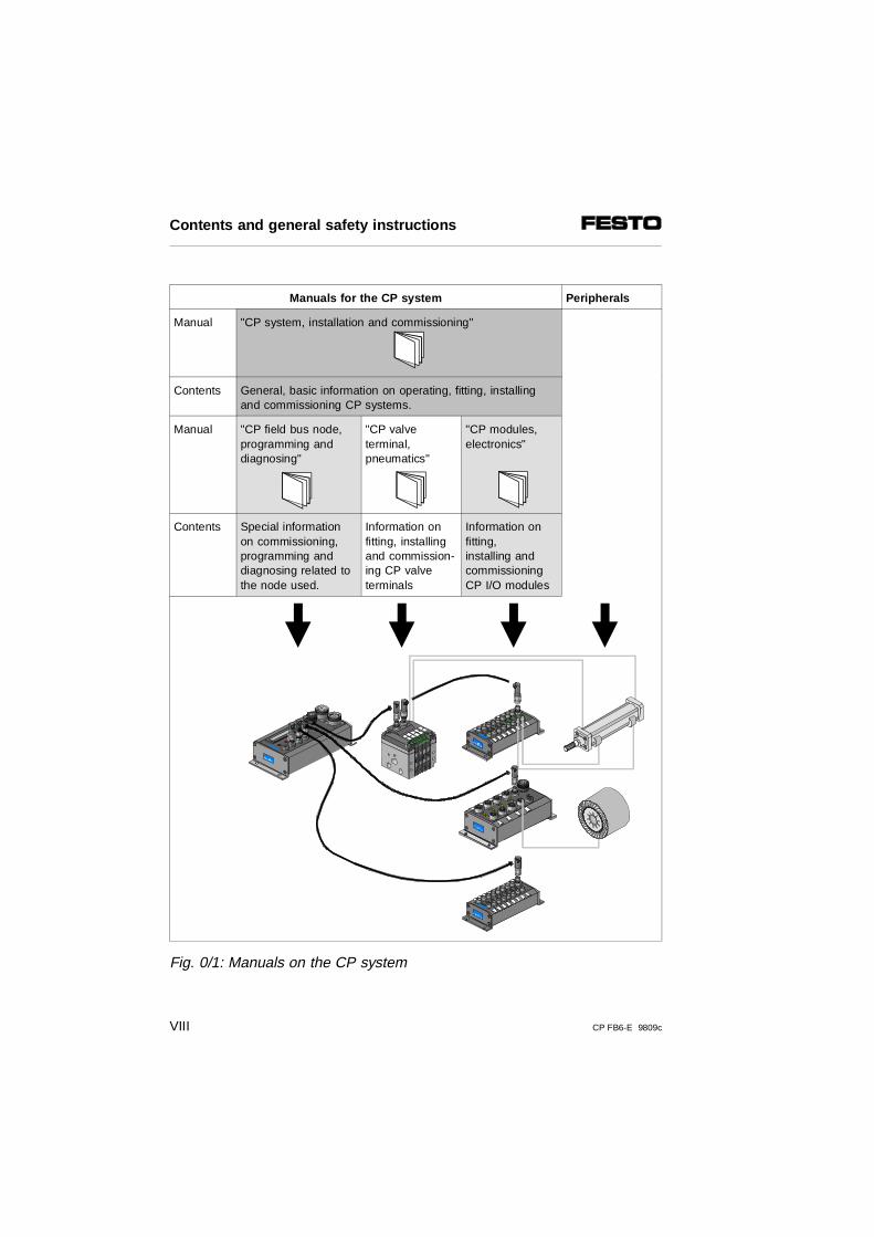
Manuals for the CP system Peripherals
Manual "CP system, installation and commissioning"
Contents General, basic information on operating, fitting, installingand commissioning CP systems.
Manual "CP field bus node,programming anddiagnosing"
"CP valveterminal,pneumatics"
"CP modules,electronics"
Contents Special informationon commissioning,programming anddiagnosing related tothe node used.
Information onfitting, installingand commission-ing CP valveterminals
Information onfitting,installing andcommissioningCP I/O modules
Fig. 0/1: Manuals on the CP system
Contents and general safety instructions
VIII CP FB6-E 9809c
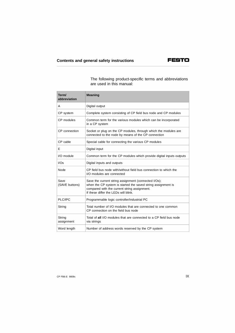
The following product-specific terms and abbreviations are used in this manual:
Term/abbreviation
Meaning
A Digital output
CP system Complete system consisting of CP field bus node and CP modules
CP modules Common term for the various modules which can be incorporatedin a CP system
CP connection Socket or plug on the CP modules, through which the modules areconnected to the node by means of the CP connection
CP cable Special cable for connecting the various CP modules
E Digital input
I/O module Common term for the CP modules which provide digital inputs outputs
I/Os Digital inputs and outputs
Node CP field bus node with/without field bus connection to which the I/O modules are connected
Save(SAVE buttons)
Save the current string assignment (connected I/Os);when the CP system is started the saved string assignment is compared with the current string assignment. If these differ the LEDs will blink.
PLC/IPC Programmable logic controller/industrial PC
String Total number of I/O modules that are connected to one commonCP connection on the field bus node
Stringassignment
Total of all I/O modules that are connected to a CP field bus node via strings
Word length Number of address words reserved by the CP system
Contents and general safety instructions
CP FB6-E 9809c IX

Contents and general safety instructions
X CP FB6-E 9809c
Chapter 1
Installation
1. Installation
CP FB6-E 9809c 1-1
Contents
1. Installation
1.1 General instructions . . . . . . . . . . . . . . . . . . . . . . . . . . . . . . . . . . 1-31.2 Setting the DIL switches. . . . . . . . . . . . . . . . . . . . . . . . . . . . . . . 1-41.3 Connecting the INTERBUS interface . . . . . . . . . . . . . . . . . . . 1-61.3.1 Floating structure . . . . . . . . . . . . . . . . . . . . . . . . . . . . . . . . . . . 1-81.3.2 Non-floating structure . . . . . . . . . . . . . . . . . . . . . . . . . . . . . . . . 1-91.4 Connection to the remote bus . . . . . . . . . . . . . . . . . . . . . . . . 1-101.4.1 Floating remote bus . . . . . . . . . . . . . . . . . . . . . . . . . . . . . . . 1-10
Connecting to optical-fibre waveguide . . . . . . . . . . . . . . . . . . . 1-101.4.2 Non-floating remote bus . . . . . . . . . . . . . . . . . . . . . . . . . . . . . 1-11
Connecting the incoming remote bus . . . . . . . . . . . . . . . . . . 1-12Connecting the continuing remote field bus . . . . . . . . . . . . . 1-13
1.5 Connection to the installation remote bus . . . . . . . . . . . . . . . 1-141.5.1 Non-floating installation remote bus . . . . . . . . . . . . . . . . . . 1-14
Connecting the incoming installation remote bus. . . . . . . . . . . 1-14Connecting the continuing installation remote bus . . . . . . . . 1-15
1.6 Connecting CP modules. . . . . . . . . . . . . . . . . . . . . . . . . . . . . . 1-161.7 Connecting the operating voltage. . . . . . . . . . . . . . . . . . . . . . . 1-17
1. Installation
1-2 CP FB6-E 9809c
1.1 General instructions
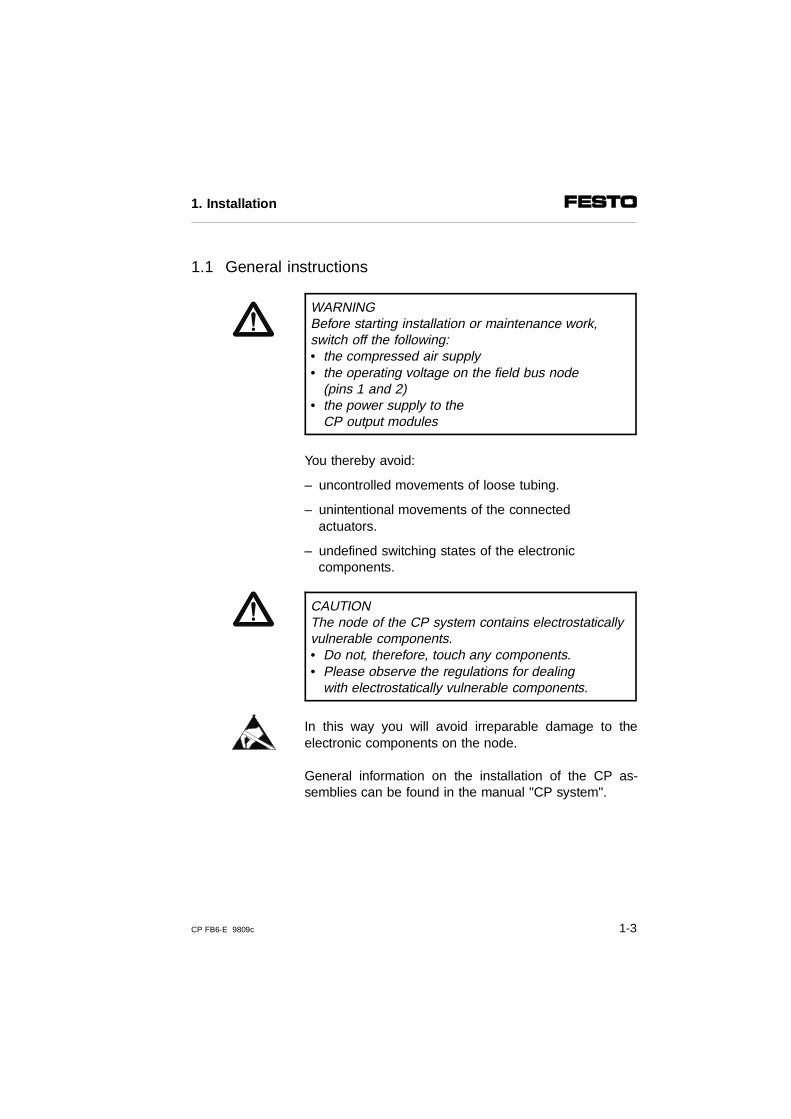
WARNINGBefore starting installation or maintenance work,switch off the following:• the compressed air supply• the operating voltage on the field bus node
(pins 1 and 2)• the power supply to the
CP output modules
You thereby avoid:
– uncontrolled movements of loose tubing.
– unintentional movements of the connectedactuators.
– undefined switching states of the electroniccomponents.
CAUTIONThe node of the CP system contains electrostaticallyvulnerable components.• Do not, therefore, touch any components.• Please observe the regulations for dealing
with electrostatically vulnerable components.
In this way you will avoid irreparable damage to theelectronic components on the node.
General information on the installation of the CP as-semblies can be found in the manual "CP system".
1. Installation
CP FB6-E 9809c 1-3
1.2 Setting the DIL switches
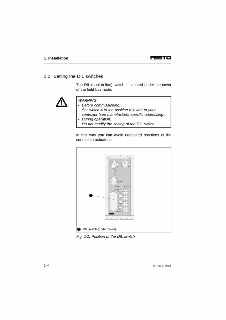
The DIL (dual in-line) switch is situated under the coverof the field bus node.
WARNING• Before commissioning:
Set switch 4 to the position relevant to your controller (see manufacturer-specific addressing).
• During operation:Do not modify the setting of the DIL switch.
In this way you can avoid undesired reactions of theconnected actuators.
1 DIL switch (under cover)
Fig. 1/1: Position of the DIL switch
1
1. Installation
1-4 CP FB6-E 9809c
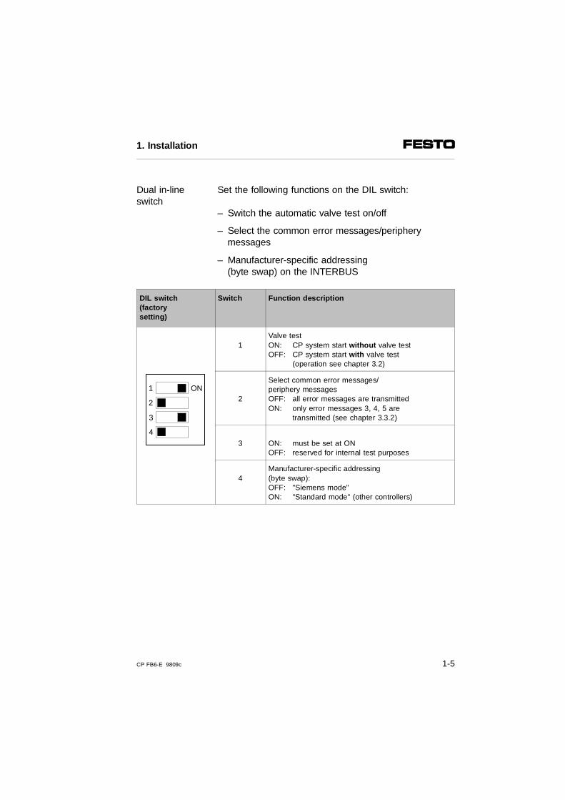
Set the following functions on the DIL switch:Dual in-lineswitch
– Switch the automatic valve test on/off
– Select the common error messages/peripherymessages
– Manufacturer-specific addressing (byte swap) on the INTERBUS
DIL switch(factorysetting)
Switch Function description
1Valve testON: CP system start without valve test OFF: CP system start with valve test
(operation see chapter 3.2)
2
Select common error messages/periphery messagesOFF: all error messages are transmittedON: only error messages 3, 4, 5 are
transmitted (see chapter 3.3.2)
3 ON: must be set at ONOFF: reserved for internal test purposes
4Manufacturer-specific addressing (byte swap):OFF: "Siemens mode"ON: "Standard mode" (other controllers)
1
2
3
4
ON
1. Installation
CP FB6-E 9809c 1-5
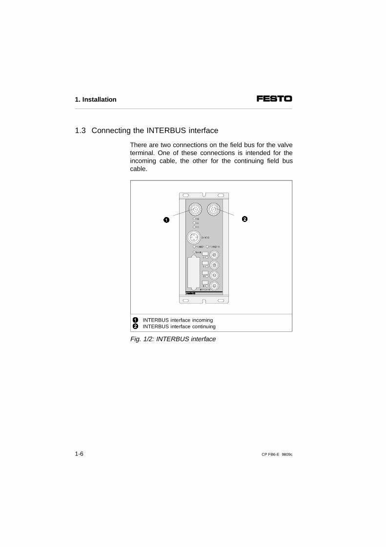
1.3 Connecting the INTERBUS interface
There are two connections on the field bus for the valveterminal. One of these connections is intended for theincoming cable, the other for the continuing field buscable.
12
INTERBUS interface incomingINTERBUS interface continuing
Fig. 1/2: INTERBUS interface
1 2
1. Installation
1-6 CP FB6-E 9809c
Different INTERBUS modules and therefore differentscreening/shielding and connection methods must beused, depending on your application.
Possible screening/shielding variants:Screening/shieldingvariants
– Floating structure: (interference suppression via RC network or con-nection to optical-fibre waveguide)
– Non-floating structure: (interference suppression via earthing on both sides)
Possible connection variants:Connectionvariants
– Remote bus (floating/non-floating)
– Remote bus with optical-fibre waveguide
– Installation remote bus (non-floating)
Please observe the following differences between theremote bus and the installation remote bus.
1. Installation
CP FB6-E 9809c 1-7
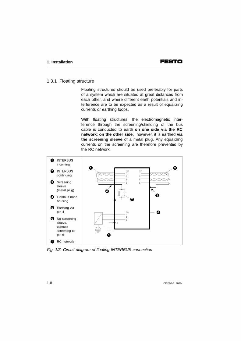
1.3.1 Floating structure
Floating structures should be used preferably for partsof a system which are situated at great distances fromeach other, and where different earth potentials and in-terference are to be expected as a result of equalizingcurrents or earthing loops.
With floating structures, the electromagnetic inter-ference through the screening/shielding of the buscable is conducted to earth on one side via the RCnetwork ; on the other side, however, it is earthed viathe screening sleeve of a metal plug. Any equalizingcurrents on the screening are therefore prevented bythe RC network.
1 INTERBUSincoming
2 INTERBUScontinuing
3 Screeningsleeve(metal plug)
4 Fieldbus nodehousing
5 Earthing viapin 4
6 No screeningsleeve,connectscreening topin 6
7 RC network
Fig. 1/3: Circuit diagram of floating INTERBUS connection
5
3
21
6
4
7
1. Installation
1-8 CP FB6-E 9809c
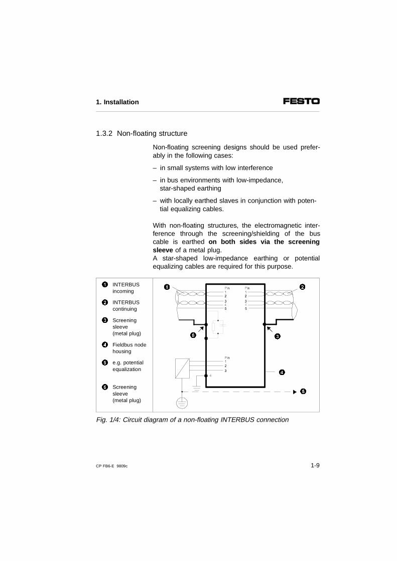
1.3.2 Non-floating structure
Non-floating screening designs should be used prefer-ably in the following cases:
– in small systems with low interference
– in bus environments with low-impedance, star-shaped earthing
– with locally earthed slaves in conjunction with poten-tial equalizing cables.
With non-floating structures, the electromagnetic inter-ference through the screening/shielding of the buscable is earthed on both sides via the screeningsleeve of a metal plug. A star-shaped low-impedance earthing or potentialequalizing cables are required for this purpose.
1 INTERBUSincoming
2 INTERBUScontinuing
3 Screeningsleeve(metal plug)
4 Fieldbus nodehousing
5 e.g. potentialequalization
6 Screeningsleeve(metal plug)
Fig. 1/4: Circuit diagram of a non-floating INTERBUS connection
5
3
21
6
4
1. Installation
CP FB6-E 9809c 1-9
1.4 Connection to the remote bus
1.4.1 Floating remote bus
The field bus node is prepared for floating operation onthe remote bus. Check the valid standards and guide-lines for your application to see if a floating structure issuited to your requirements. Further information on in-stalling an INTERBUS system can be found in the IN-TERBUS installation manual. Obtainable from:Phoenix Contact GmbH & Co.Postfach 134132 819 Blomberg, Germany
Article: IBS SYS INST UMOrder no. : 27 54 28 6
Connecting to optical-fibre waveguide
Connection to the bus can also be made with a optical-fibre waveguide. Contact connectors offer a ready-to-use data transfer system "ZYLIN RS485" for this pur-pose. This can be connected to the valve terminal. TheZYLIN RS485 system is self-supplying and consists oftwo pin-compatible 9-pin IP 67 round plugs, integratedoptoelectronics and plastic optical-fibre waveguide.
1. Installation
1-10 CP FB6-E 9809c
Advantages:– large transmission band width– insensitive to electrical and magnetic interference– low weight– low space requirements
Further information, order forms and technical specifica-tions can be obtained from:Fa. Contact Connectors GmbHGewerbestrasse 3070565 Stuttgart, Germany
Internet: Lappgroup.com
1.4.2 Non-floating remote bus
The plugs or sockets and cables listed below can beobtained from the suppliers quoted. The plugs orsockets are suitable only for the cables named here.You must order different plugs if you wish to use cableswith other outer diameters, as the dimensions of thescreening sleeve and the inner diameter of the cablemust fit exactly.
Address of suppliers
Plug/socket Cable
CONINVERS GmbHDaimlerstr. 13D-71083 HerrenbergGermany
PhoenixPostfach 1341D-32819 BlombergGermany
1. Installation
CP FB6-E 9809c 1-11

Connecting the incoming remote bus
PLEASE NOTEAlways connect the screening/shielding to both sidesof the sleeve.
Incomingremote bus
Pin no. * Designation Meaning
1 DO Data out
2 /DO Data out inverse
3 DI Data in
4 /DI Data in inverse
5 Earth/GND Reference conductor
Sleeve Screening Screening/shielding
* Do not connect pins not listed here
Plug selection Part no.
9-pin plug with socket insert,screened/shielded with sleeve/housing.Possible designs:a) straight socketb) angled socketc) angled socket (locking)
a) RC-09 S 1 N 128 049b) RC-09 S 1 N 12T 049c) RC-09 S 3 N 12T 0Z0
Cable selection
LIYCY 3x2x0.25 mm2
IBS RBC METER-T28 06 28 6
9
1
2 3
4
5
678
1. Installation
1-12 CP FB6-E 9809c
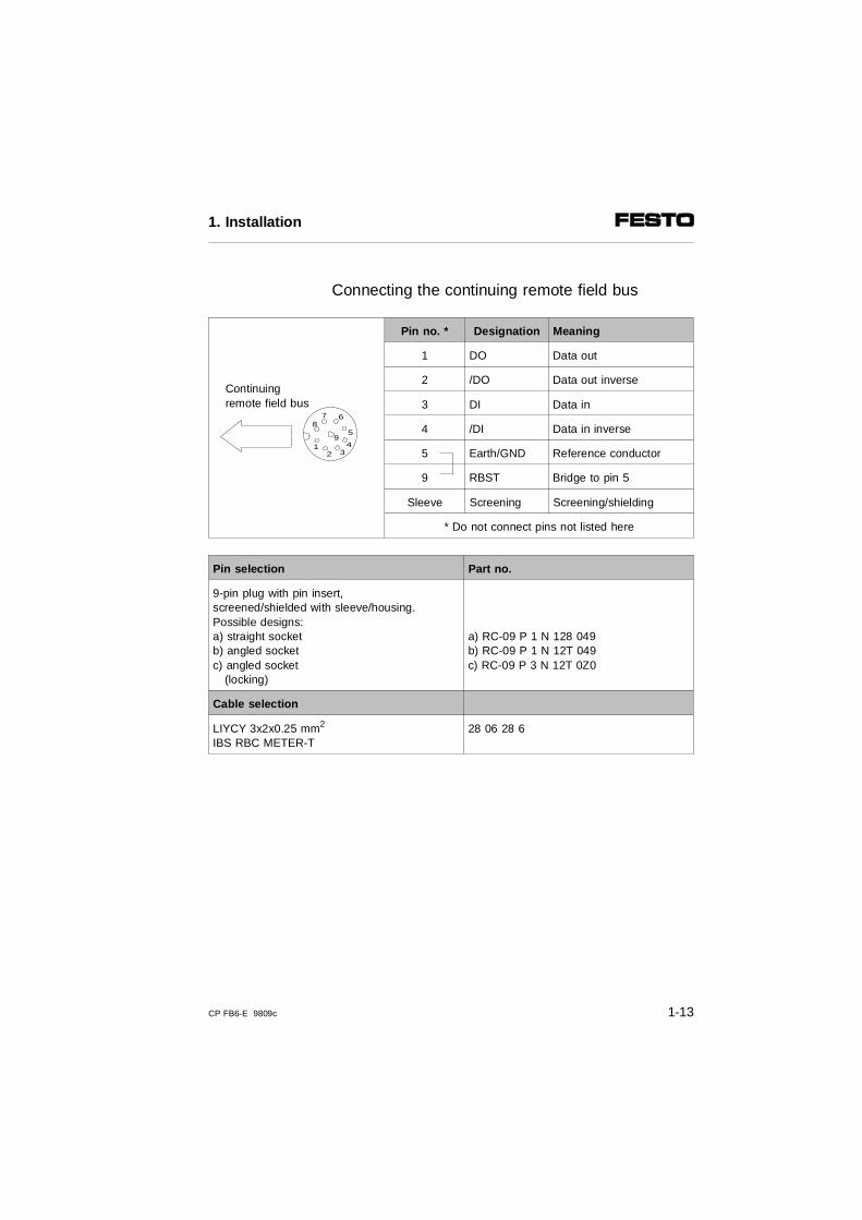
Connecting the continuing remote field bus
Continuingremote field bus
Pin no. * Designation Meaning
1 DO Data out
2 /DO Data out inverse
3 DI Data in
4 /DI Data in inverse
5 Earth/GND Reference conductor
9 RBST Bridge to pin 5
Sleeve Screening Screening/shielding
* Do not connect pins not listed here
Pin selection Part no.
9-pin plug with pin insert,screened/shielded with sleeve/housing.Possible designs:a) straight socketb) angled socketc) angled socket (locking)
a) RC-09 P 1 N 128 049b) RC-09 P 1 N 12T 049c) RC-09 P 3 N 12T 0Z0
Cable selection
LIYCY 3x2x0.25 mm2 IBS RBC METER-T
28 06 28 6
9
87 6
5
432
1
1. Installation
CP FB6-E 9809c 1-13
1.5 Connection to the installation remote bus
1.5.1 Non-floating installation remote bus
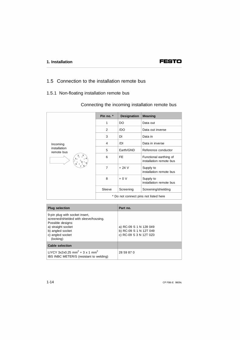
Connecting the incoming installation remote bus
Incominginstallationremote bus
Pin no. * Designation Meaning
1 DO Data out
2 /DO Data out inverse
3 DI Data in
4 /DI Data in inverse
5 Earth/GND Reference conductor
6 FE Functional earthing ofinstallation remote bus
7 + 24 V Supply toinstallation remote bus
8 + 0 V Supply toinstallation remote bus
Sleeve Screening Screening/shielding
* Do not connect pins not listed here
Plug selection Part no.
9-pin plug with socket insert,screened/shielded with sleeve/housing.Possible designs:a) straight socketb) angled socketc) angled socket (locking)
a) RC-09 S 1 N 128 049b) RC-09 S 1 N 12T 049c) RC-09 S 3 N 12T 0Z0
Cable selection
LIYCY 3x2x0.25 mm2 + 3 x 1 mm2
IBS INBC METER/S (resistant to welding)28 59 87 0
9
1
2 3
4
5
678
1. Installation
1-14 CP FB6-E 9809c
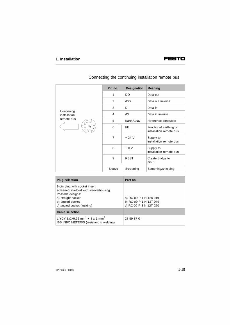
Connecting the continuing installation remote bus
Continuinginstallationremote bus
Pin no. Designation Meaning
1 DO Data out
2 /DO Data out inverse
3 DI Data in
4 /DI Data in inverse
5 Earth/GND Reference conductor
6 FE Functional earthing ofinstallation remote bus
7 + 24 V Supply toinstallation remote bus
8 + 0 V Supply to installation remote bus
9 RBST Create bridge to pin 5
Sleeve Screening Screening/shielding
Plug selection Part no.
9-pin plug with socket insert,screened/shielded with sleeve/housing.Possible designs:a) straight socketb) angled socketc) angled socket (locking)
a) RC-09 P 1 N 128 049b) RC-09 P 1 N 12T 049c) RC-09 P 3 N 12T 0Z0
Cable selection
LIYCY 3x2x0.25 mm2 + 3 x 1 mm2
IBS INBC METER/S (resistant to welding)28 59 87 0
9
87 6
5
432
1
1. Installation
CP FB6-E 9809c 1-15
1.6 Connecting CP modules
WARNING• Use the special cable (type KVI-CP-1-...) from
Festo for connecting the CP modules to a string.• The total cable length on one string must not
exceed 10 m.
You thereby avoid:
– faults in data exchange between the node and theconnected CP modules.
Information on this procedure can be found in the ma-nual "CP system, installation and commissioning."
1. Installation
1-16 CP FB6-E 9809c
1.7 Connecting the operating voltage
WARNINGUse only power units which guarantee reliable elec-trical isolation of the operating voltages as per IEC 742/EN 60742/VDE 0551 with at least 4 kV isolation resistance (protected extra low voltage,PELV). Switch power packs are permitted if they guarantee reliable isolation as per EN 60950/VDE 0805.
Remark:By using PELV power units, protection against electricshock (protection against direct and indirect contact) inaccordance with EN 60204-1/IEC 204 is guaranteed onFesto valve terminals.Safety transformers with the adjacent designation mustbe used for supplying PELV networks. The valve termi-nals must be earthed in order to ensure their function(e.g. EMC).
Information on this procedure as well as the connectingcables and current consumption can be found in themanual "CP system, installation and commissioning."
1. Installation
CP FB6-E 9809c 1-17

1. Installation
1-18 CP FB6-E 9809c

Chapter 2
Commissioning
2. Commissioning
CP FB6-E 9809c 2-1
Contents
2. Commissioning
2.1 Preparing the CP system for operation on the INTERBUS . . . 2-32.1.1 Operating voltage . . . . . . . . . . . . . . . . . . . . . . . . . . . . . . . . . . 2-32.1.2 Saving the string assignment . . . . . . . . . . . . . . . . . . . . . . . . 2-32.2 Preparing the INTERBUS interface module . . . . . . . . . . . . . . . 2-42.2.1 Creating the configuration list . . . . . . . . . . . . . . . . . . . . . . . . . . 2-42.2.2 Bus configuration via the CMD software . . . . . . . . . . . . . . . . . . 2-5
Inserting with the Ident-code . . . . . . . . . . . . . . . . . . . . . . . . . . . 2-6Insert Device Description . . . . . . . . . . . . . . . . . . . . . . . . . . . . . . 2-8
2.2.3 Bus configuration without CMD software . . . . . . . . . . . . . . . . . 2-12Logical addressing . . . . . . . . . . . . . . . . . . . . . . . . . . . . . . . . 2-12Physical addressing . . . . . . . . . . . . . . . . . . . . . . . . . . . . . . . 2-15Ascertaining the number of bits for the process data channel per CP system . . . . . . . . . . . . . . . . . . . . . . . . . . . . . . 2-16
2.3 Commissioning the CP system on the INTERBUS . . . . . . . . . 2-172.4 Configuration . . . . . . . . . . . . . . . . . . . . . . . . . . . . . . . . . . . . . . 2-192.4.1 Addressing the inputs/outputs . . . . . . . . . . . . . . . . . . . . . . . . . 2-192.4.2 Manufacturer-specific addressing (byte swap) . . . . . . . . . . 2-212.4.3 Process data assignment via the CMD software (byte swap) . 2-242.4.4 Other instructions . . . . . . . . . . . . . . . . . . . . . . . . . . . . . . . . . . . 2-27
Preprocessing . . . . . . . . . . . . . . . . . . . . . . . . . . . . . . . . . . . . . . 2-27Periphery faults (PF). . . . . . . . . . . . . . . . . . . . . . . . . . . . . . . . . 2-27Commissioning tips. . . . . . . . . . . . . . . . . . . . . . . . . . . . . . . . . . 2-28
2. Commissioning
2-2 CP FB6-E 9809c
2.1 Preparing the CP system for operation on the INTERBUS
2.1.1 Operating voltage
PLEASE NOTE• The CP fieldbus node must have a separate
operating voltage supply.The operating voltage for the remote bus/installationremote bus is not used by the CP system. This volt-age is looped through in order to supply further INTERBUS slaves.
2.1.2 Saving the string assignment
PLEASE NOTEBefore commissioning the CP system, you must firstprepare the CP system (see "CP System" manual).
Before commissioning the CP system on the INTERBUS, proceed as follows:
1. Connect the operating voltage for the node(see "CP system" manual).
2. Connect the CP modules.
3. Switch on the operating voltage.
4. Save the string assignment by pressing the SAVEbutton.
5. Switch off the operating voltage for the node.
2. Commissioning
CP FB6-E 9809c 2-3
2.2 Preparing the INTERBUS interface module
2.2.1 Creating the configuration list
Before commissioning or programming you must createa configuration list of all connected field bus stations.On the basis of this list, you can:
Configurationlist
• Make a comparison between the NOMINAL andACTUAL configurations, in order to detect any addressing errors
• Access these specifications during a syntax check ofa program, in order to avoid addressing errors.
Configuration of the CP system requires a very accu-rate procedure, as different configuration specificationsmay be required for each system due to the modularstructure. Please also observe the specifications in sub-sequent sections.
2. Commissioning
2-4 CP FB6-E 9809c
2.2.2 Bus configuration via the CMD software
This chapter describes as an example the main stepswhich you will require in the CMD software, in order toinsert a Festo CP system in your project. A general andcomprehensive description can be found in the relevantmanual for the CMD software. It is assumed here thatthe user is already familiar with the information in theCMD manual.
PLEASE NOTEThe software packages are subjected to modificationswhich are not taken into account in this manual.
The examples of screen displays used here are takenfrom the CMD software version 4.
Further and current information can be found in themanual for your CMD software.
2. Commissioning
CP FB6-E 9809c 2-5
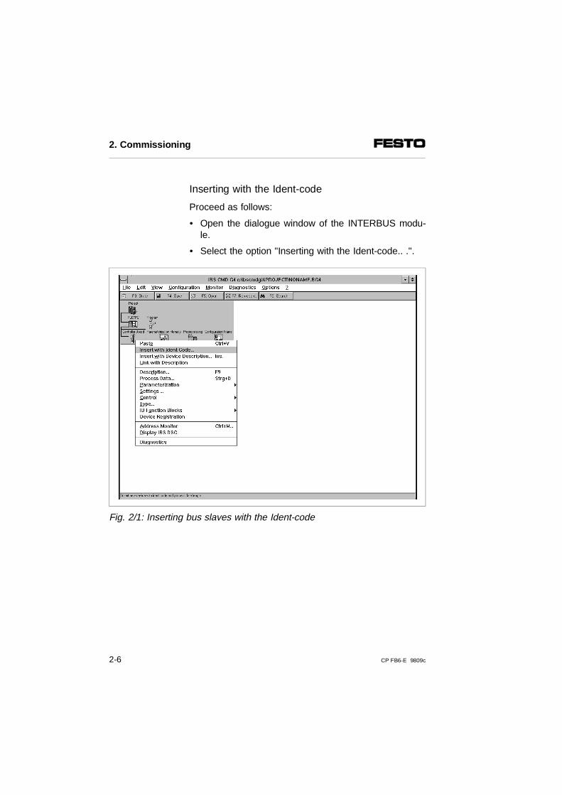
Inserting with the Ident-code
Proceed as follows:
• Open the dialogue window of the INTERBUS modu-le.
• Select the option "Inserting with the Ident-code.. .".
Fig. 2/1: Inserting bus slaves with the Ident-code
2. Commissioning
2-6 CP FB6-E 9809c
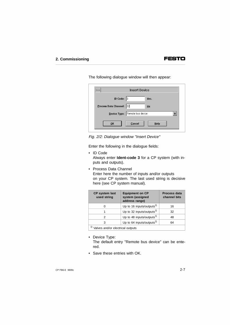
The following dialogue window will then appear:
Fig. 2/2: Dialogue window "Insert Device"
Enter the following in the dialogue fields:
• ID CodeAlways enter Ident-code 3 for a CP system (with in-puts and outputs).
• Process Data ChannelEnter here the number of inputs and/or outputson your CP system. The last used string is decisivehere (see CP system manual).
CP system lastused string
Equipment on CPsystem (assignedaddress range)
Process datachannel bits
0 Up to 16 inputs/outputs1) 16
1 Up to 32 inputs/outputs1) 32
2 Up to 48 inputs/outputs1) 48
3 Up to 64 inputs/outputs1) 641) Valves and/or electrical outputs
• Device Type:The default entry "Remote bus device" can be ente-red.
• Save these entries with OK.
2. Commissioning
CP FB6-E 9809c 2-7

Insert Device Description
In the dialogue window below you can describe theslave and enter information about the valve terminal,e.g. the name of the station and a picture of the slave.
Fig. 2/3: Dialogue window "Insert Device Description"
2. Commissioning
2-8 CP FB6-E 9809c
Possible entries:
• Profile NumberThe Festo CP system complies with the INTERBUSI/O profile 12H. Enter this value in the box "ProfileNumber."
• Interface TypeThe default entry "Interface Universal” can be trans-ferred. Alternatively you can select thetypes Remote bus or Installation remote bus.
• IconOpen the dialogue window "Icon ...,”, if you wish touse specific icons for the Festo CP system.
PLEASE NOTE The specific icons for the Festo valve terminals canbe found on the accompanying CD-ROM. • If necessary, read the file "Readme.txt" on the
CD-ROM, in order to obtain a brief summary of thecontents of the CD-ROM.
• Copy the file "Festo.ICL" into the CMD directory \PICTURE\.
2. Commissioning
CP FB6-E 9809c 2-9
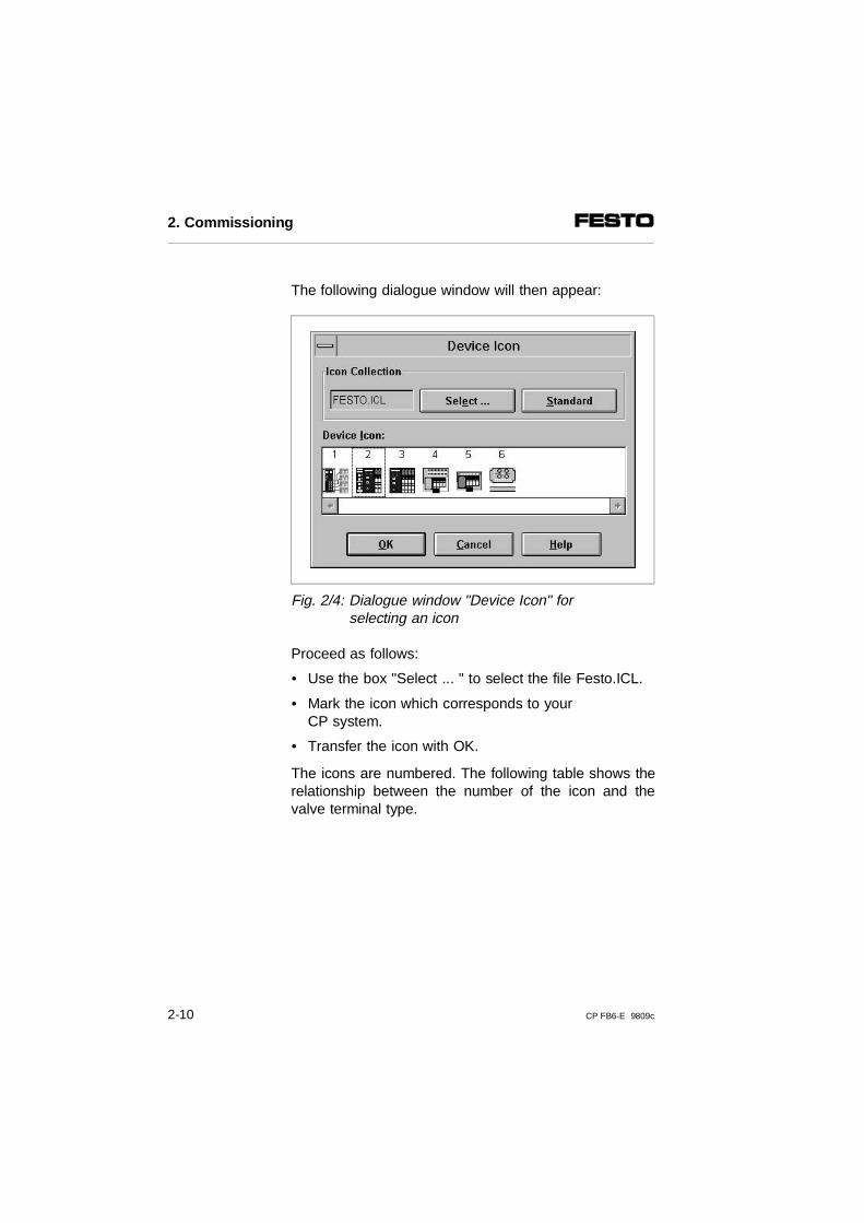
The following dialogue window will then appear:
Fig. 2/4: Dialogue window "Device Icon" for selecting an icon
Proceed as follows:
• Use the box "Select ... " to select the file Festo.ICL.
• Mark the icon which corresponds to your CP system.
• Transfer the icon with OK.
The icons are numbered. The following table shows therelationship between the number of the icon and thevalve terminal type.
2. Commissioning
2-10 CP FB6-E 9809c
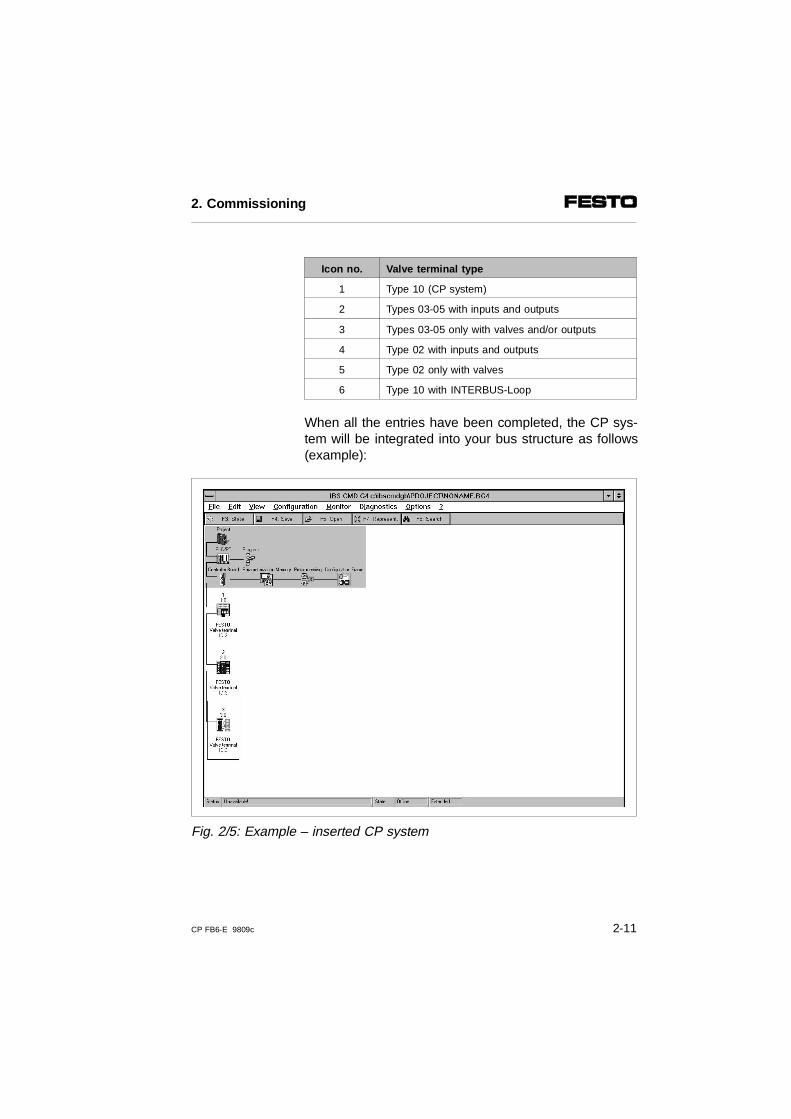
Icon no. Valve terminal type
1 Type 10 (CP system)
2 Types 03-05 with inputs and outputs
3 Types 03-05 only with valves and/or outputs
4 Type 02 with inputs and outputs
5 Type 02 only with valves
6 Type 10 with INTERBUS-Loop
When all the entries have been completed, the CP sys-tem will be integrated into your bus structure as follows(example):
Fig. 2/5: Example – inserted CP system
2. Commissioning
CP FB6-E 9809c 2-11
2.2.3 Bus configuration without CMD software
The CP system supports the following addressing andprogramming variants, depending on the module youare using:
– logical addressing
– physical addressing
Logical addressing
PLEASE NOTE• ID CODE
Always configure a CP system (with inputs and outputs1)) with Ident code 3.
1)Valve coils and/or electrical outputs
One or more configuration lists have been created inthe PLC or in the INTERBUS module for logical ad-dressing. These lists contain at least the following en-tries:
– the ID codes of all slaves
– the logical addresses of all slaves
– the number of inputs
– the number of outputs
2. Commissioning
2-12 CP FB6-E 9809c
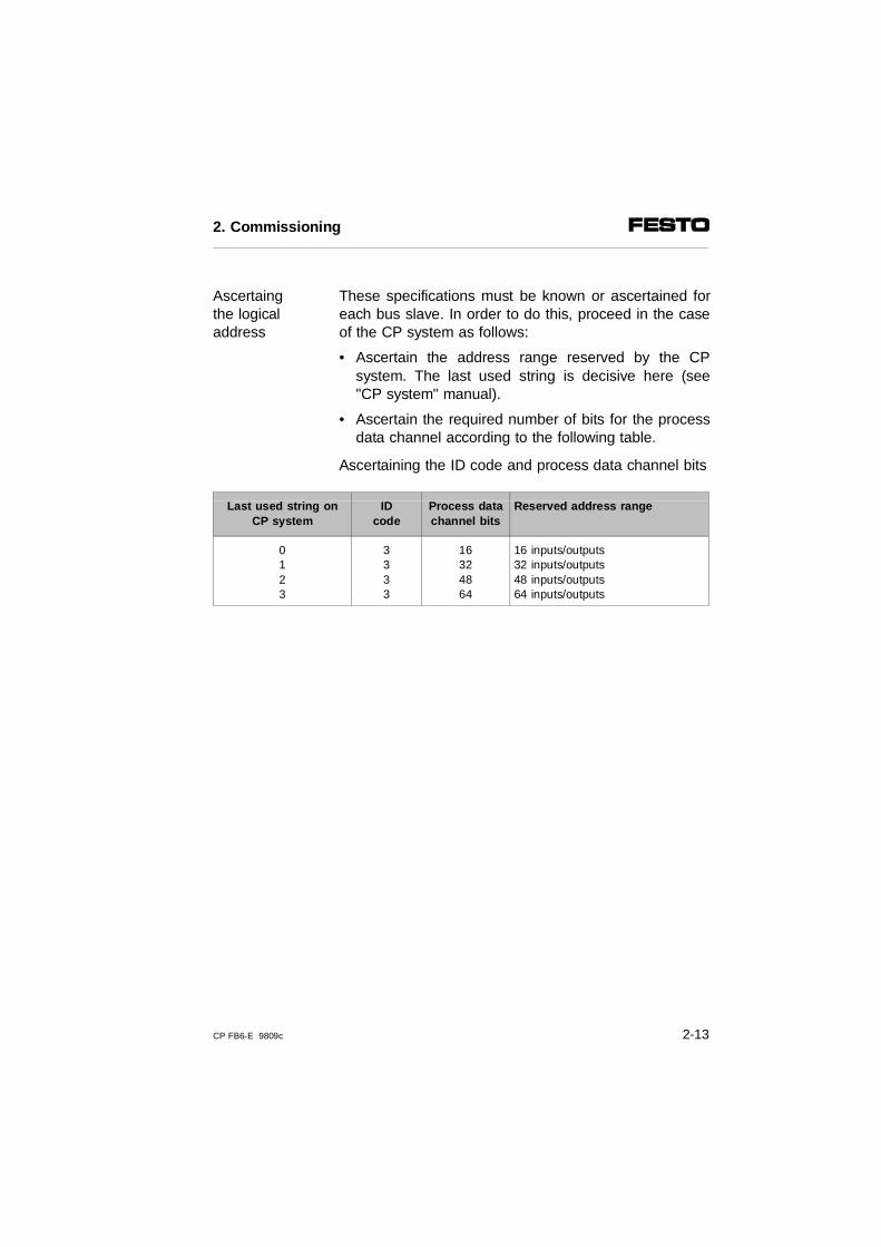
These specifications must be known or ascertained foreach bus slave. In order to do this, proceed in the caseof the CP system as follows:
Ascertaingthe logicaladdress
• Ascertain the address range reserved by the CPsystem. The last used string is decisive here (see"CP system" manual).
• Ascertain the required number of bits for the processdata channel according to the following table.
Ascertaining the ID code and process data channel bits
Last used string onCP system
IDcode
Process datachannel bits
Reserved address range
0123
3333
16324864
16 inputs/outputs 32 inputs/outputs 48 inputs/outputs 64 inputs/outputs
2. Commissioning
CP FB6-E 9809c 2-13
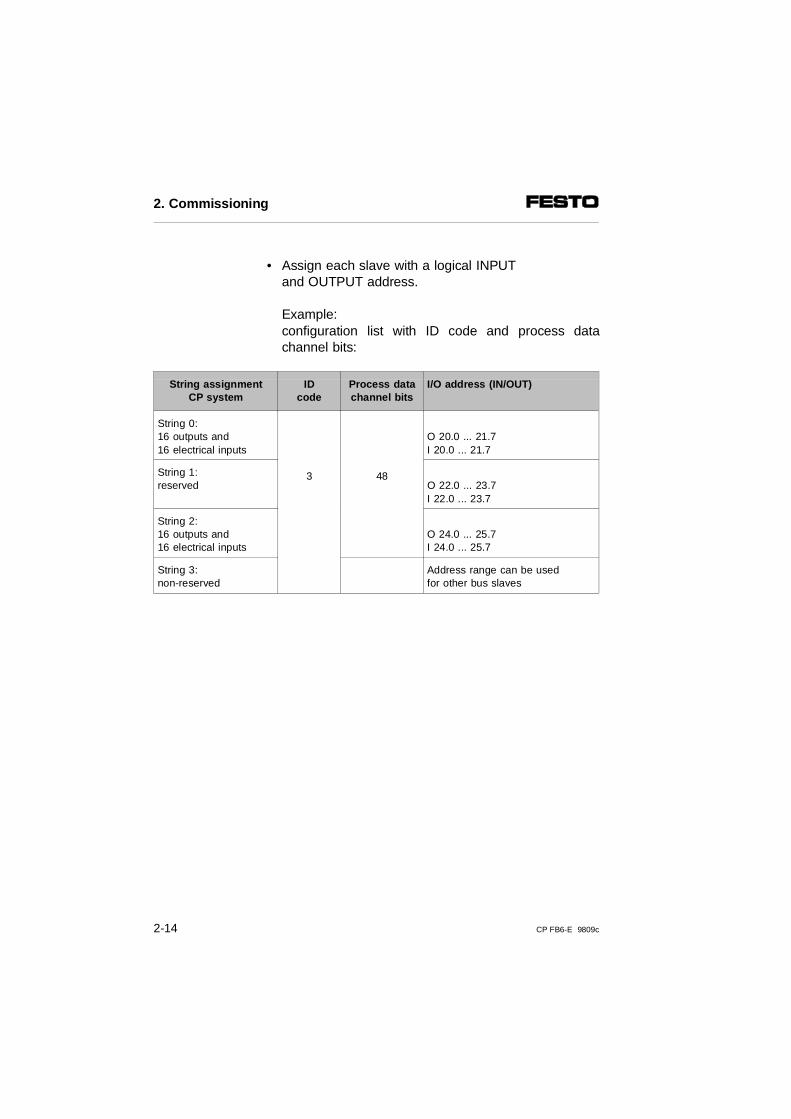
• Assign each slave with a logical INPUT and OUTPUT address.
Example: configuration list with ID code and process datachannel bits:
String assignmentCP system
IDcode
Process datachannel bits
I/O address (IN/OUT)
String 0:16 outputs and16 electrical inputs
3 48
O 20.0 ... 21.7I 20.0 ... 21.7
String 1:reserved O 22.0 ... 23.7
I 22.0 ... 23.7
String 2:16 outputs and16 electrical inputs
O 24.0 ... 25.7I 24.0 ... 25.7
String 3:non-reserved
Address range can be used for other bus slaves
2. Commissioning
2-14 CP FB6-E 9809c
Physical addressing
PLEASE NOTEUse the logical addressing or the bus configurationvia the CMD software, if your INTERBUS modulepermits this.You can thereby avoid shifting input and output ad-dresses during any later extensions.
The first bus slave is addressed with the basis addressof the INTERBUS module. You can obtain the addressof the next bus slave by adding to the basis addressthe appropriate number of bits in the process datachannel of all the slaves. This process must be carriedout separately for the inputs and the outputs.
PLEASE NOTEThe number of inputs on a CP system may differfrom the number of outputs.
1. Ascertain the address range reserved by the CPsystem. The last used string is decisive here (see"CP system" manual).
2. Ascertain the required number of bits for the processdata channel according to the following table.
3. Calculate the physical addresses of all the slaves(see following example).
2. Commissioning
CP FB6-E 9809c 2-15
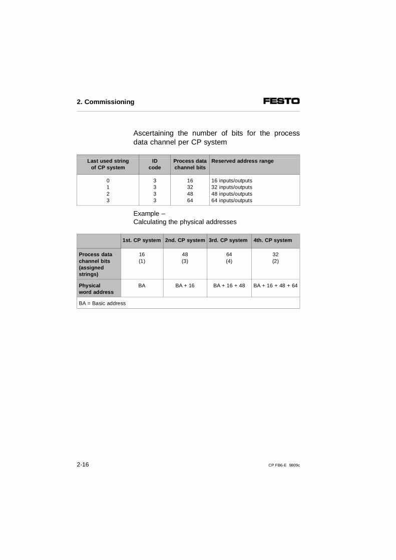
Ascertaining the number of bits for the processdata channel per CP system
Last used stringof CP system
IDcode
Process datachannel bits
Reserved address range
0123
3333
16324864
16 inputs/outputs 32 inputs/outputs 48 inputs/outputs64 inputs/outputs
Example –Calculating the physical addresses
1st. CP system 2nd. CP system 3rd. CP system 4th. CP system
Process datachannel bits(assigned strings)
16(1)
48(3)
64(4)
32(2)
Physicalword address
BA BA + 16 BA + 16 + 48 BA + 16 + 48 + 64
BA = Basic address
2. Commissioning
2-16 CP FB6-E 9809c
2.3 Commissioning the CP system on the INTERBUS
PLEASE NOTEThe switching-on instructions in the manual for theINTERBUS module must also be observed.
Proceed as follows:
1. Connect the INTERBUS cables to the field busnode.
2. Switch on the operating voltages:• for all remote bus/installation remote bus slaves, • for the CP system.
3. Switch on the operating voltage for the master module.
When you switch your controller on, it will automaticallycarry out a comparison between the NOMINAL and AC-TUAL configurations. For this configuration run it is im-portant that:
Configura-tion run
– the specifications for the NOMINAL configuration arecomplete and correct.
– the power supplies to the PLC and to the field busslaves are switched on either simultaneously or inthe sequence specified above.The bus is not able to operate until all the bus slavesare switched on.
2. Commissioning
CP FB6-E 9809c 2-17
If the message "PF periphery fault" occurs when theoperating voltages are switched on (pin 1 of the fieldbus node), the operating voltage is probably notswitched on at pin 2. This will lead to an error messagebecause of the factory setting of the DIL switch.
Recommendation.If the safety concept of your machine/system permits,commission the CP system with both operating voltages(pins 1 and 2), but without compressed air.In this way, you have the possibility of testing withoutthe risk of undesired reactions.
2. Commissioning
2-18 CP FB6-E 9809c
2.4 Configuration
2.4.1 Addressing the inputs/outputs
Further specifications on addressing and programmingcan be found in the manuals for your controller and theINTERBUS module.
PLEASE NOTEA CP valve location occupies two addresses. The following applies:- lower-value address: pilot solenoid 14- higher-value address: pilot solenoid 12
The address assignment (process data assignment) ofthe CP inputs/outputs and of the CP valve terminal onthe INTERBUS or compatible bus systems dependsprincipally on the INTERBUS module and your control-ler.
CAUTIONThere are different address assignments on the INTERBUS. This is due to the assignment of the processing data within the INTERBUS module andnot within the Festo CP system. • Make sure that DIL switch element 4 is set
correctly for your addressing (see chapter 1).• Observe the position of the high and low bytes
(byte n/n+1) when assigning the addresses for theCP system, as the position of these bytes may beswapped in the case of some control systems.
You thereby avoid errors in addressing the inputs/out-puts.
2. Commissioning
CP FB6-E 9809c 2-19
The following examples show the different address as-signments and the position of the low byte (n) and thehigh byte (n+1). A distinction is made here between the:
– Siemens mode and the
– Standard mode
Example:
– In the Siemens mode the lower value output byte(byte n) is mapped on valve coils 0-7 of the valveterminal, byte n+1 is mapped on coils (8-15), etc.
– In the Standard mode the lower value output byte(byte n) is mapped on valve coils 8-15 of the valveterminal, byte n+1 is mapped on coils 0-7.
In the following chapters you will find instructions onmodifying the position of the low bytes and high bytes("Byte swap").
– with hardware by means of the DIL switch setting(chapter 2.4.2, "Manufacturer-specific addressing bymeans of the DIL switch")
– with software in a user-friendly manner by re-addres-sing with the CMD software (chapter 2.4.3 "Processdata assignment by means of CMD software”). TheDIL switch setting remains unchanged (factory set-ting).
2. Commissioning
2-20 CP FB6-E 9809c
2.4.2 Manufacturer-specific addressing (byte swap)
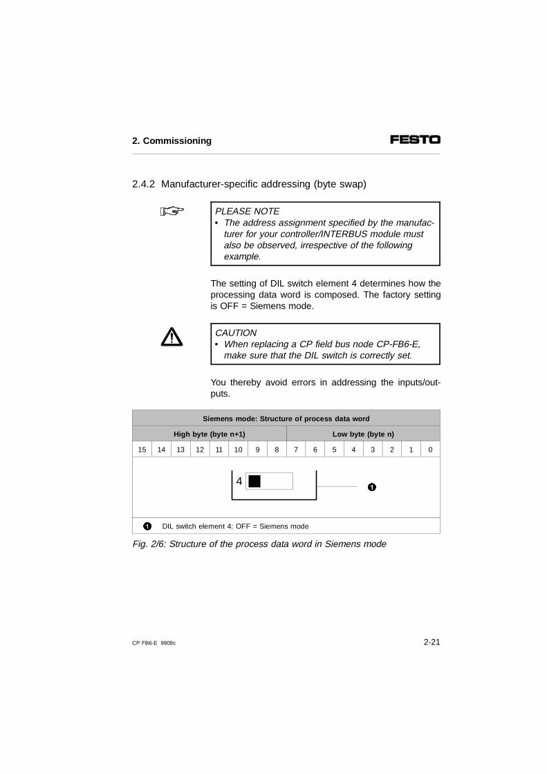
PLEASE NOTE• The address assignment specified by the manufac-
turer for your controller/INTERBUS module mustalso be observed, irrespective of the following example.
The setting of DIL switch element 4 determines how theprocessing data word is composed. The factory settingis OFF = Siemens mode.
CAUTION• When replacing a CP field bus node CP-FB6-E,
make sure that the DIL switch is correctly set.
You thereby avoid errors in addressing the inputs/out-puts.
Siemens mode: Structure of process data word
High byte (byte n+1) Low byte (byte n)
15 14 13 12 11 10 9 8 7 6 5 4 3 2 1 0
1 DIL switch element 4: OFF = Siemens mode
Fig. 2/6: Structure of the process data word in Siemens mode
41
2. Commissioning
CP FB6-E 9809c 2-21
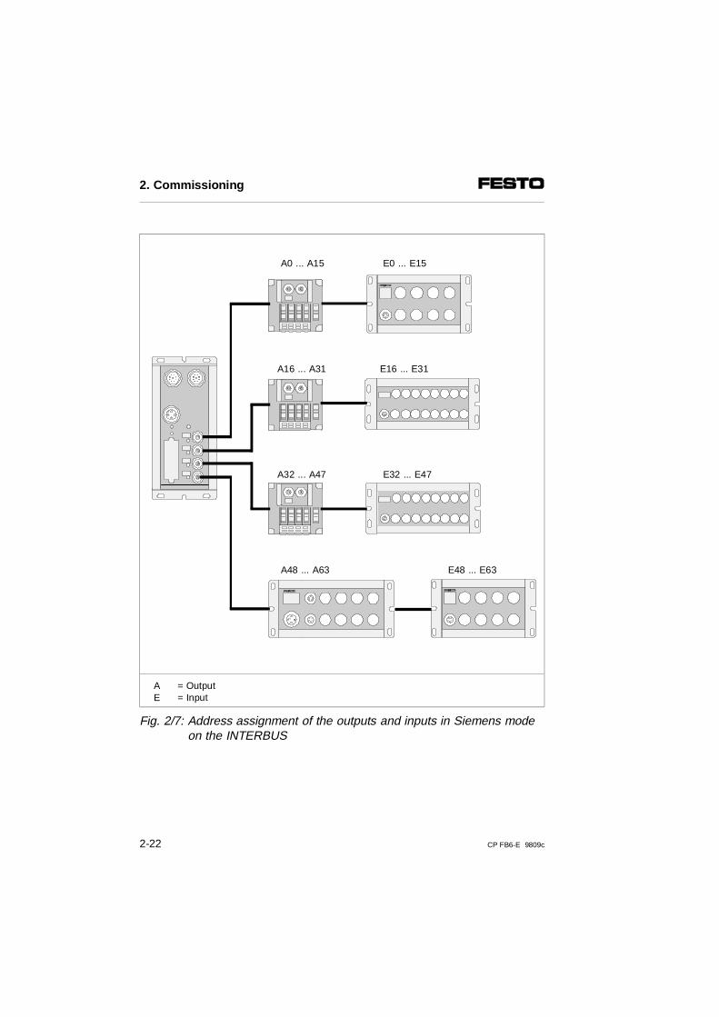
AE
= Output= Input
Fig. 2/7: Address assignment of the outputs and inputs in Siemens modeon the INTERBUS
A0 ... A15 E0 ... E15
A16 ... A31 E16 ... E31
A32 ... A47 E32 ... E47
A48 ... A63 E48 ... E63
2. Commissioning
2-22 CP FB6-E 9809c
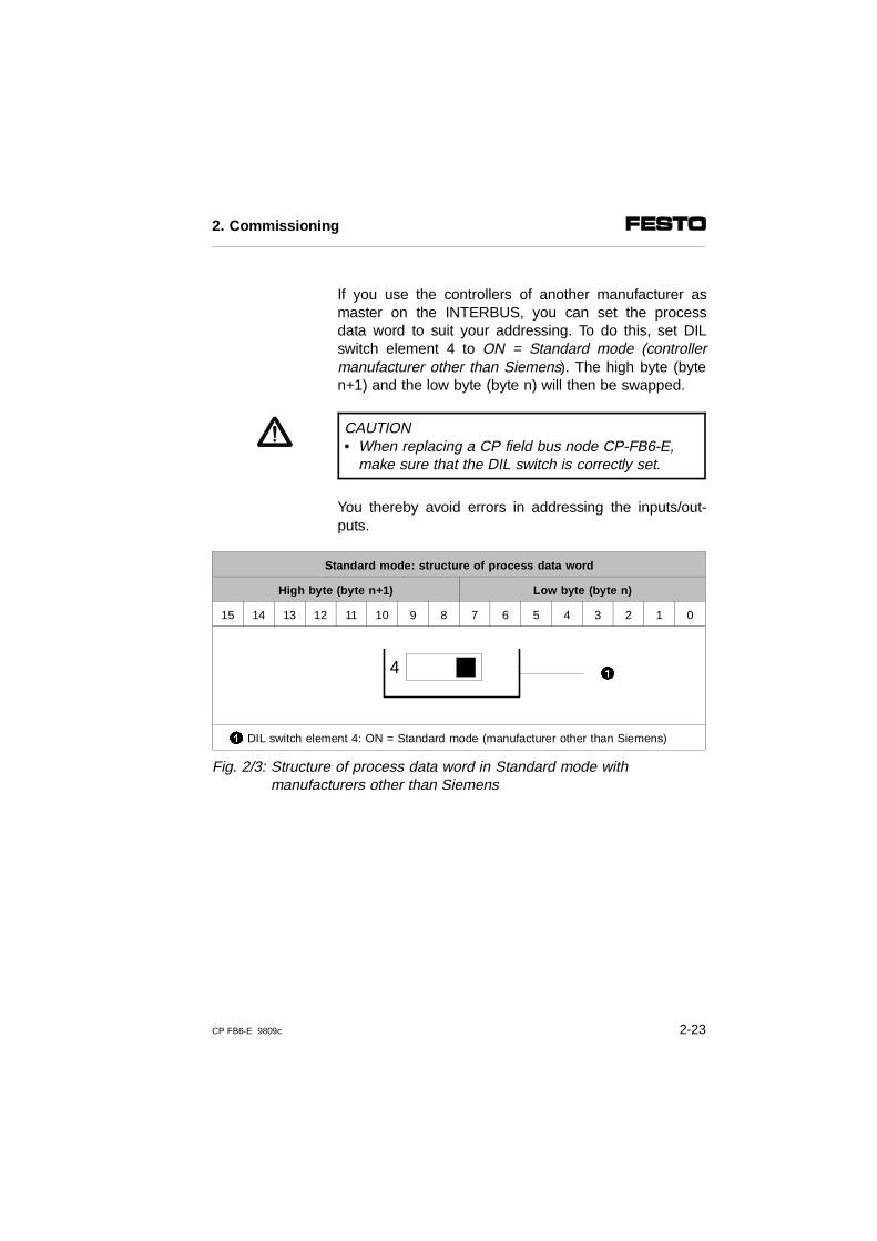
If you use the controllers of another manufacturer asmaster on the INTERBUS, you can set the processdata word to suit your addressing. To do this, set DILswitch element 4 to ON = Standard mode (controllermanufacturer other than Siemens). The high byte (byten+1) and the low byte (byte n) will then be swapped.
CAUTION• When replacing a CP field bus node CP-FB6-E,
make sure that the DIL switch is correctly set.
You thereby avoid errors in addressing the inputs/out-puts.
Standard mode: structure of process data word
High byte (byte n+1) Low byte (byte n)
15 14 13 12 11 10 9 8 7 6 5 4 3 2 1 0
1 DIL switch element 4: ON = Standard mode (manufacturer other than Siemens)
Fig. 2/3: Structure of process data word in Standard mode withmanufacturers other than Siemens
4 1
2. Commissioning
CP FB6-E 9809c 2-23
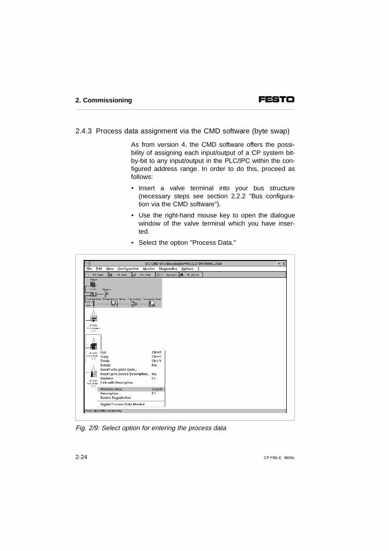
2.4.3 Process data assignment via the CMD software (byte swap)
As from version 4, the CMD software offers the possi-bility of assigning each input/output of a CP system bit-by-bit to any input/output in the PLC/IPC within the con-figured address range. In order to do this, proceed asfollows:
• Insert a valve terminal into your bus structure(necessary steps see section 2.2.2 "Bus configura-tion via the CMD software").
• Use the right-hand mouse key to open the dialoguewindow of the valve terminal which you have inser-ted.
• Select the option "Process Data."
Fig. 2/9: Select option for entering the process data
2. Commissioning
2-24 CP FB6-E 9809c
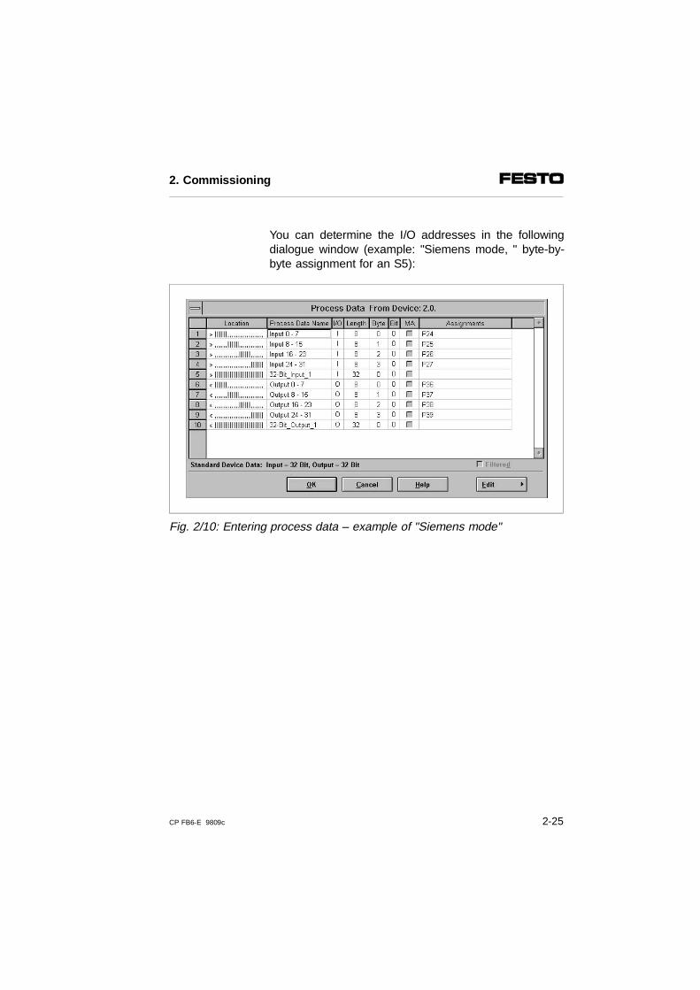
You can determine the I/O addresses in the followingdialogue window (example: "Siemens mode, " byte-by-byte assignment for an S5):
Fig. 2/10: Entering process data – example of "Siemens mode"
2. Commissioning
CP FB6-E 9809c 2-25
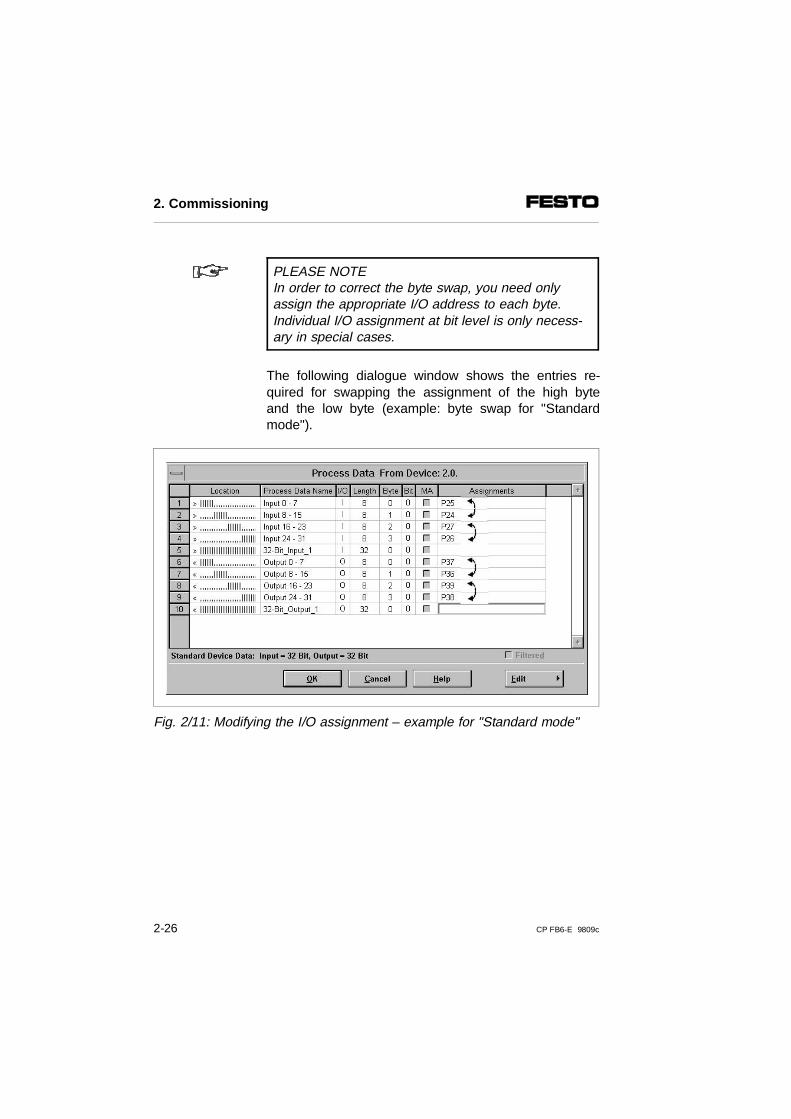
PLEASE NOTEIn order to correct the byte swap, you need only assign the appropriate I/O address to each byte.Individual I/O assignment at bit level is only necess-ary in special cases.
The following dialogue window shows the entries re-quired for swapping the assignment of the high byteand the low byte (example: byte swap for "Standardmode").
Fig. 2/11: Modifying the I/O assignment – example for "Standard mode"
2. Commissioning
2-26 CP FB6-E 9809c
2.4.4 Other instructions
Preprocessing
Under preprocessing on the INTERBUS we understandthe logical linking of the processing data within the IN-TERBUS module (previously called "Event programm-ing" or "Receive bit manipulation").
PLEASE NOTEAll the inputs/outputs of a CP system can be prepro-cessed.
Periphery faults (PF)
If a fault is recognized by the CP system, a peripheryfault will also be triggered, transmitted to the moduleand displayed there. The causes of the fault in the CPsystem can, however, be partly suppressed (see Chap-ter 3.3.2).
Periphery faults do not cause the system to stop. Youcan determine the reaction to periphery faults by par-ametrizing the module. You can also acknowledge theperiphery fault by parametrizing the INTERBUS mo-dule.
2. Commissioning
CP FB6-E 9809c 2-27
Commissioning tips
If the error message "PF" appears when the operatingvoltage is switched on, one of the causes is that theoperating voltage for the valves and electrical outputs isnot switched on (pin 2 of the operating voltage connec-tion of the valve terminal is without voltage). This is al-ways the case when the load voltage is not switched onuntil after the power-up phase of the controller. Due tothe factory setting of DIL switch element 2, this leadscorrectly to an error message.
Recommendation: In this case, switch off the monitoring of the valve/out-put voltage and evaluate the undervoltage message viathe diagnostic status register.
2. Commissioning
2-28 CP FB6-E 9809c

Chapter 3
Diagnosis
3. Diagnosis
CP FB6-E 9809c 3-1
Contents
3. Diagnosis
3.1 LED displays on the bus node . . . . . . . . . . . . . . . . . . . . . . . . . 3-33.1.2 Normal operating status . . . . . . . . . . . . . . . . . . . . . . . . . . . . . . 3-43.1.3 Diagnosis operating voltage POWER or POWER V . . . . . . . . . 3-53.1.4 Diagnostic bus LEDs . . . . . . . . . . . . . . . . . . . . . . . . . . . . . . . 3-63.2 Testing the valves . . . . . . . . . . . . . . . . . . . . . . . . . . . . . . . . . . 3-8
Starting the test routine . . . . . . . . . . . . . . . . . . . . . . . . . . . . . . . 3-9Stopping the test routine . . . . . . . . . . . . . . . . . . . . . . . . . . . . . . 3-9
3.3 Diagnosis via INTERBUS . . . . . . . . . . . . . . . . . . . . . . . . . . . . 3-103.3.1 Diagnostic status register . . . . . . . . . . . . . . . . . . . . . . . . . . . . . 3-103.3.2 Periphery fault (PF) . . . . . . . . . . . . . . . . . . . . . . . . . . . . . . . . . 3-113.4 Reaction to faults in the control system . . . . . . . . . . . . . . . . . 3-12
3. Diagnosis
3-2 CP FB6-E 9809c
3.1 LED displays on the bus node
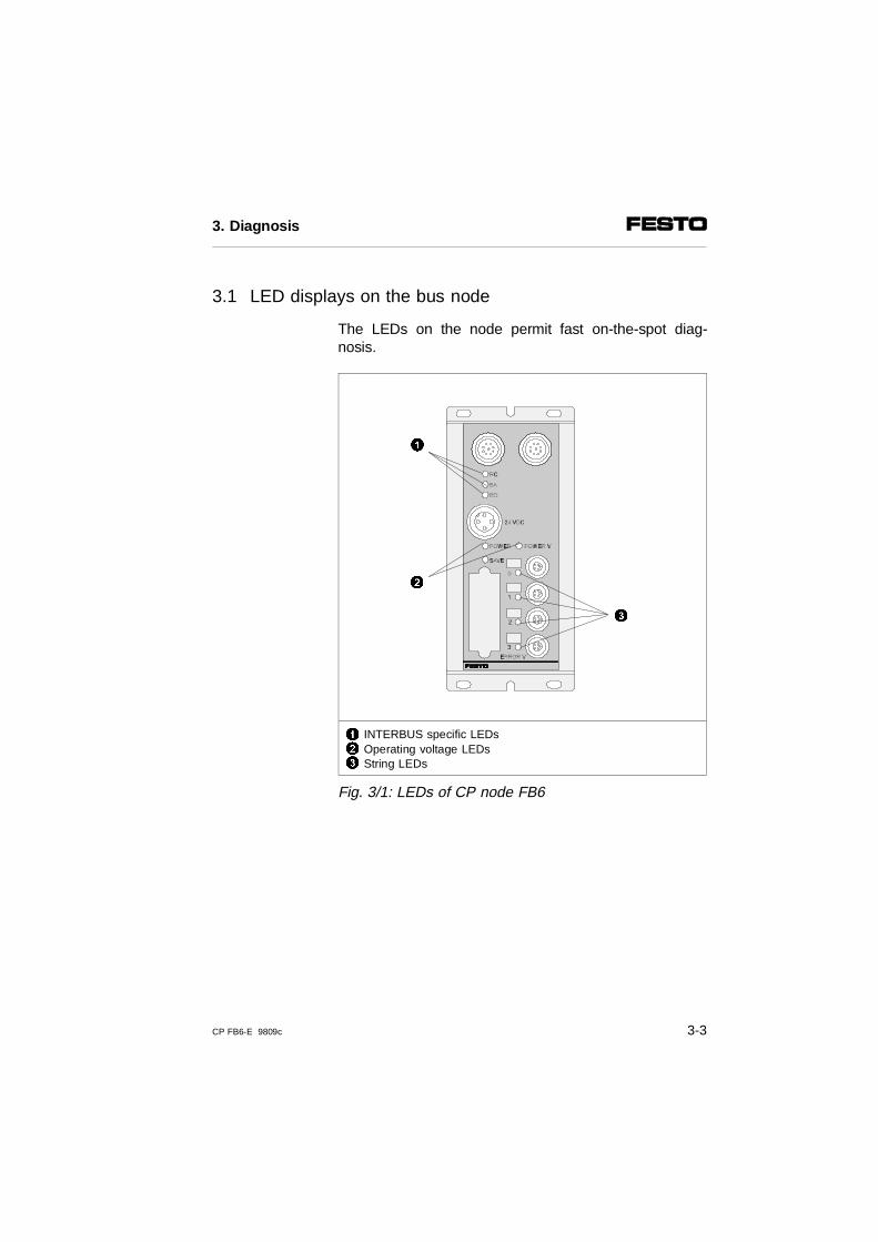
The LEDs on the node permit fast on-the-spot diag-nosis.
123
INTERBUS specific LEDsOperating voltage LEDsString LEDs
Fig. 3/1: LEDs of CP node FB6
1
2
3
3. Diagnosis
CP FB6-E 9809c 3-3
LEDs LED designation Meaning
RC Remote bus check Lights up when connection is made to the master
BA Bus active Lights up during data transfer
RD Remote bus disable Lighs up when data transferon the bus is interrupted orwhen interface "REMOTE OUT"is switched off.
POWER Operating voltage display ofinternal electronics
Lights up when operatingvoltage is applied to pin 1 andthe node is ready to operate.
POWER V Operating voltage display ofvalves
Lights up when operatingvoltage is OK (pin 2)
0..3 CP string LED In starting phase:blinks if the string assignmenthas been modified since lastoperation.
During operation: lights up if a CP connectionis interrupted.
3.1.2 Normal operating status
In normal operating status the following LEDs on CPnode 6 light up:
( = lights up; = LED flashes; = out)
LEDs Operating status Error treatment
RC BA RD
POWERPOWER V
0...3 ERROR
normal none
3. Diagnosis
3-4 CP FB6-E 9809c
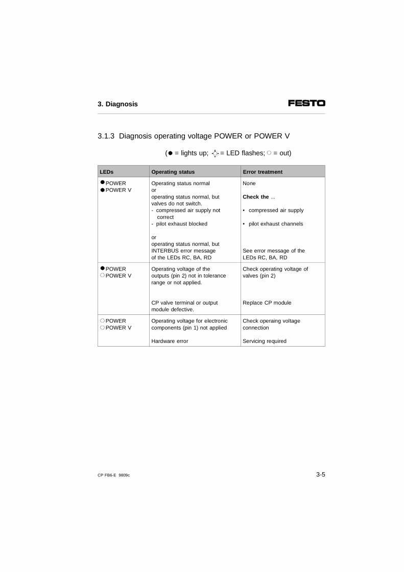
3.1.3 Diagnosis operating voltage POWER or POWER V
( = lights up; = LED flashes; = out)
LEDs Operating status Error treatment
POWER POWER V
Operating status normaloroperating status normal, but valves do not switch.- compressed air supply not
correct- pilot exhaust blocked
oroperating status normal, but INTERBUS error messageof the LEDs RC, BA, RD
None
Check the ...
• compressed air supply
• pilot exhaust channels
See error message of theLEDs RC, BA, RD
POWERPOWER V
Operating voltage of the outputs (pin 2) not in tolerancerange or not applied.
CP valve terminal or output module defective.
Check operating voltage of valves (pin 2)
Replace CP module
POWERPOWER V
Operating voltage for electroniccomponents (pin 1) not applied
Hardware error
Check operaing voltageconnection
Servicing required
3. Diagnosis
CP FB6-E 9809c 3-5
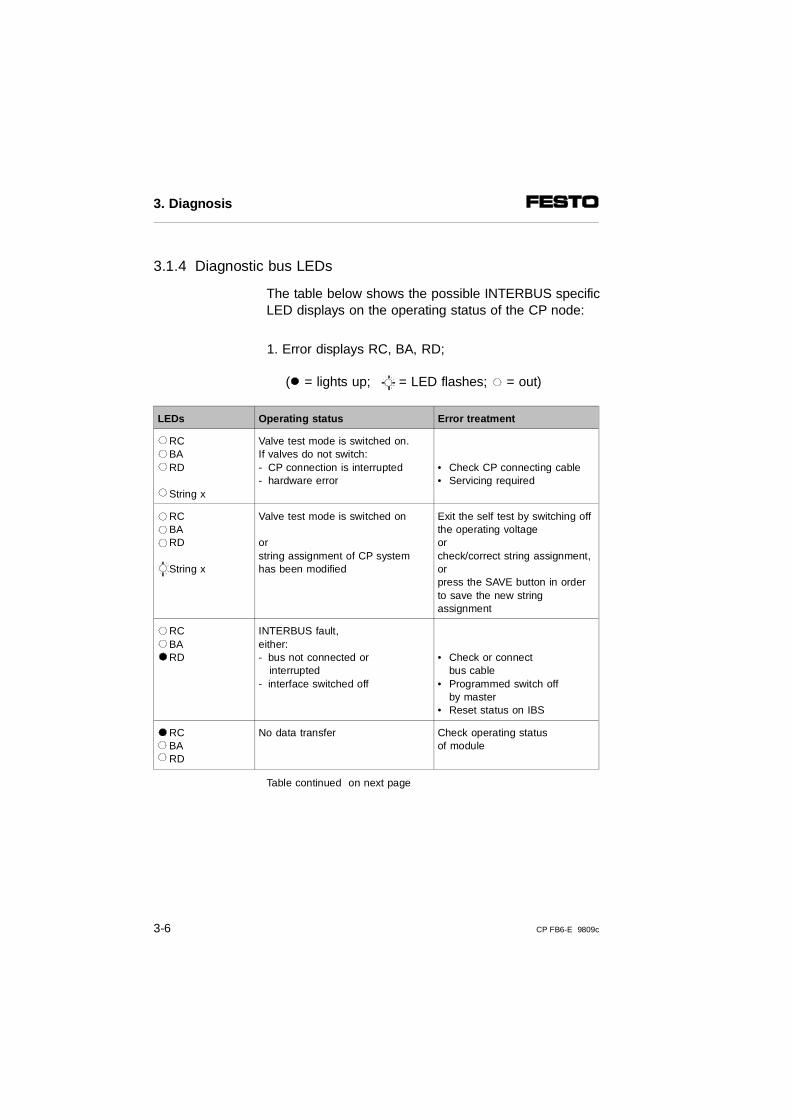
3.1.4 Diagnostic bus LEDs
The table below shows the possible INTERBUS specificLED displays on the operating status of the CP node:
1. Error displays RC, BA, RD;
( = lights up; = LED flashes; = out)
LEDs Operating status Error treatment
RCBARD
String x
Valve test mode is switched on.If valves do not switch:- CP connection is interrupted- hardware error
• Check CP connecting cable• Servicing required
RCBARD
String x
Valve test mode is switched on
orstring assignment of CP systemhas been modified
Exit the self test by switching offthe operating voltageorcheck/correct string assignment,or press the SAVE button in orderto save the new stringassignment
RCBARD
INTERBUS fault, either:- bus not connected or interrupted- interface switched off
• Check or connect bus cable
• Programmed switch offby master
• Reset status on IBS
RCBARD
No data transfer Check operating statusof module
Table continued on next page
3. Diagnosis
3-6 CP FB6-E 9809c
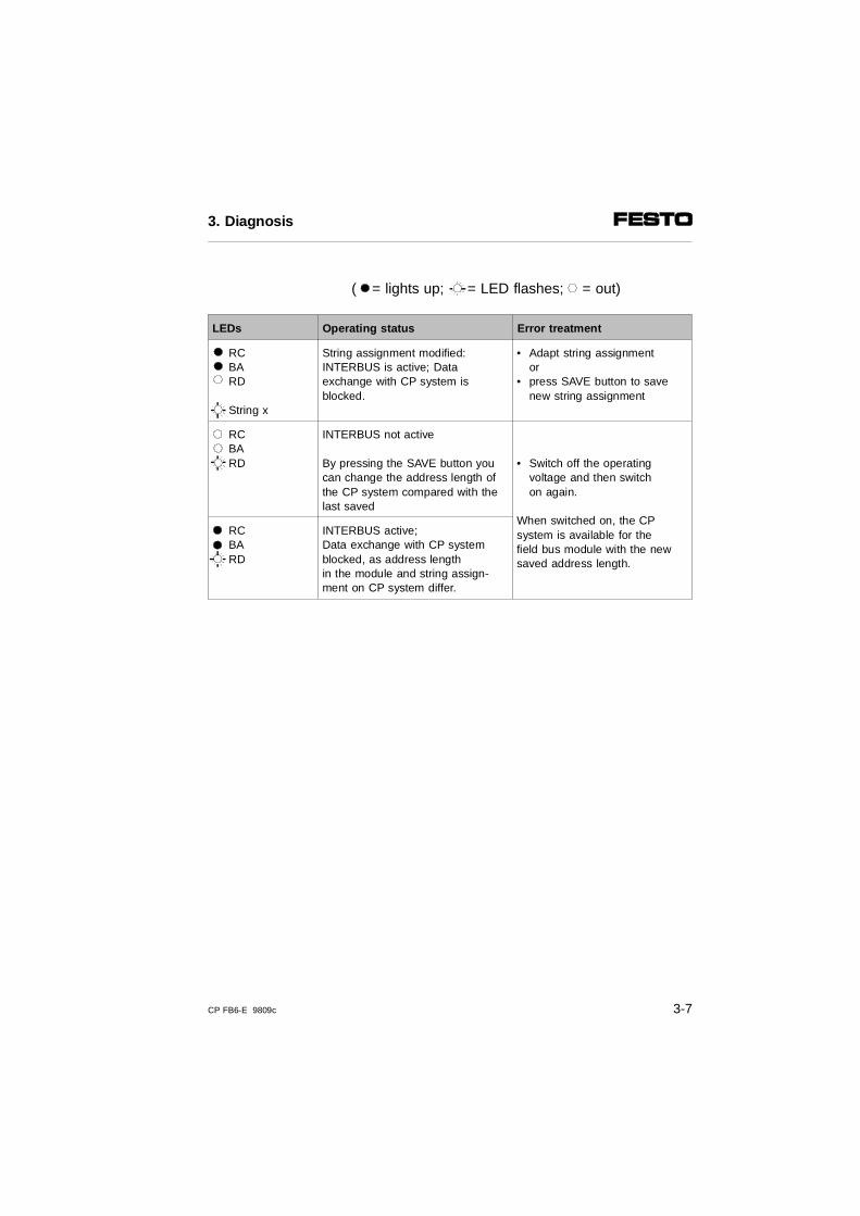
( = lights up; = LED flashes; = out)
LEDs Operating status Error treatment
RC BA RD
String x
String assignment modified:INTERBUS is active; Data exchange with CP system isblocked.
• Adapt string assignmentor
• press SAVE button to save new string assignment
RC BA RD
INTERBUS not active
By pressing the SAVE button youcan change the address length ofthe CP system compared with the last saved
• Switch off the operating voltage and then switch on again.
When switched on, the CPsystem is available for thefield bus module with the newsaved address length.
RC BA RD
INTERBUS active;Data exchange with CP systemblocked, as address length in the module and string assign-ment on CP system differ.
3. Diagnosis
CP FB6-E 9809c 3-7
3.2 Testing the valves
WARNING Before starting the test, switch off the compressedair supply to the valves.
You thereby avoid undesired or dangerous movements of the actuators.
CAUTION• This test function runs automatically in the CP
valve terminals. All valves are switched on/off cyclically.
• All programmed interlocks or continue conditionsare ignored.
During the test routine of the CP terminal, all the valveswill be switched on/off at 1 second intervals.
Test routine
3. Diagnosis
3-8 CP FB6-E 9809c
Starting the test routine
1. Switch off the operating voltages (pins 1 and 2) atthe node.
2. Switch off the operating voltages at the output modules.
3. Remove the DIL switch cover.
4. Note the settings of the DIL switch.
5. Set DIL switch element 1 to OFF.
6. Switch on the operating voltages (pins 1 and 2).
7. Set DIL switch element 1 to ON within 5 seconds.
If the 5 second interval is exceeded, the CP valve ter-minal/CP system will resume normal operation.
Then switch on the operating voltage at the output modules again.
Stopping the test routine
1. Switch off the operating voltages (pins 1 and 2) ofthe terminal.
As DIL switch element 1 is set to ON = Test routine offthe CP system will start again when the power is switched on without the test routine.
3. Diagnosis
CP FB6-E 9809c 3-9
3.3 Diagnosis via INTERBUS
The CP system makes available the following diagnostic options via the INTERBUS:
– Entries in the diagnostic status register of the module.
3.3.1 Diagnostic status register
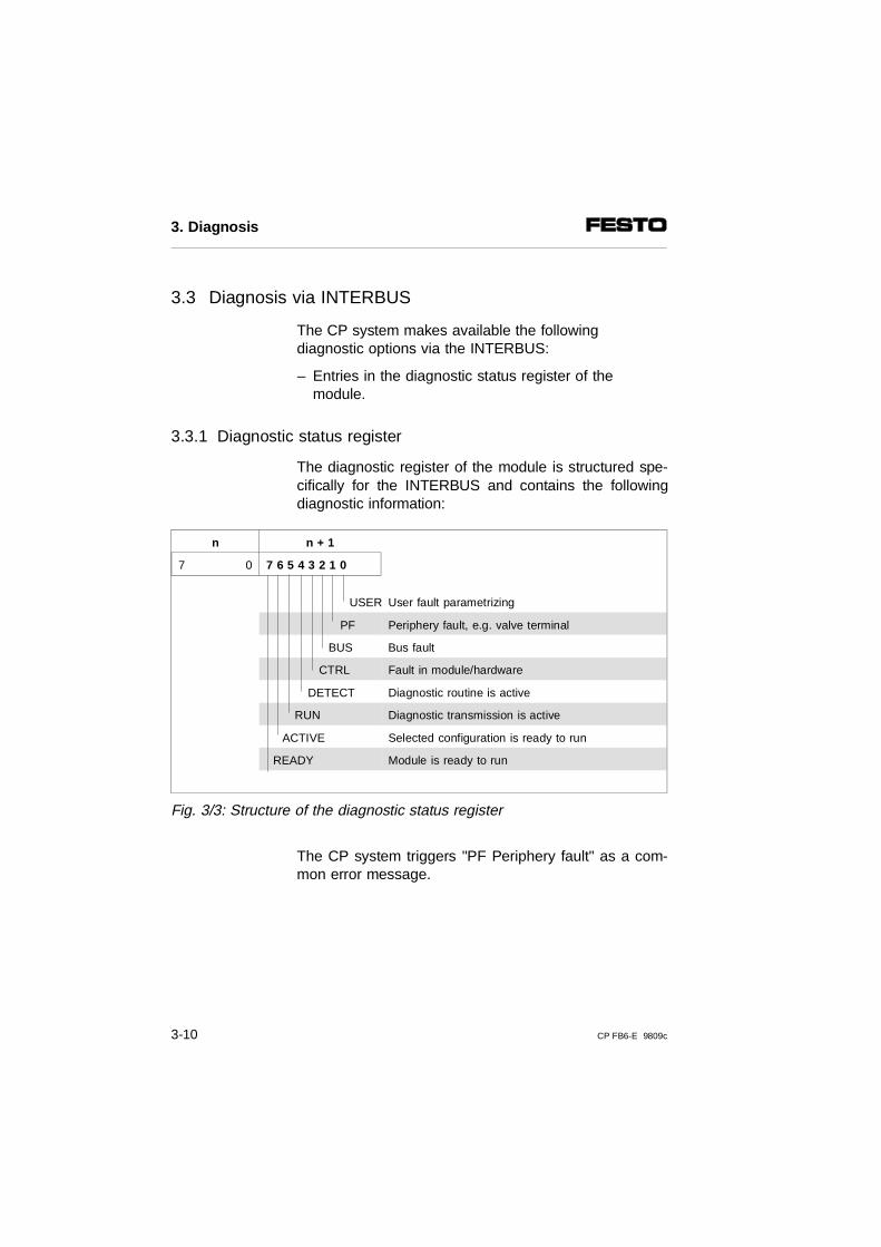
The diagnostic register of the module is structured spe-cifically for the INTERBUS and contains the followingdiagnostic information:
n n + 1
7 0 7 6 5 4 3 2 1 0
USER User fault parametrizing
PF Periphery fault, e.g. valve terminal
BUS Bus fault
CTRL Fault in module/hardware
DETECT Diagnostic routine is active
RUN Diagnostic transmission is active
ACTIVE Selected configuration is ready to run
READY Module is ready to run
Fig. 3/3: Structure of the diagnostic status register
The CP system triggers "PF Periphery fault" as a com-mon error message.
3. Diagnosis
3-10 CP FB6-E 9809c
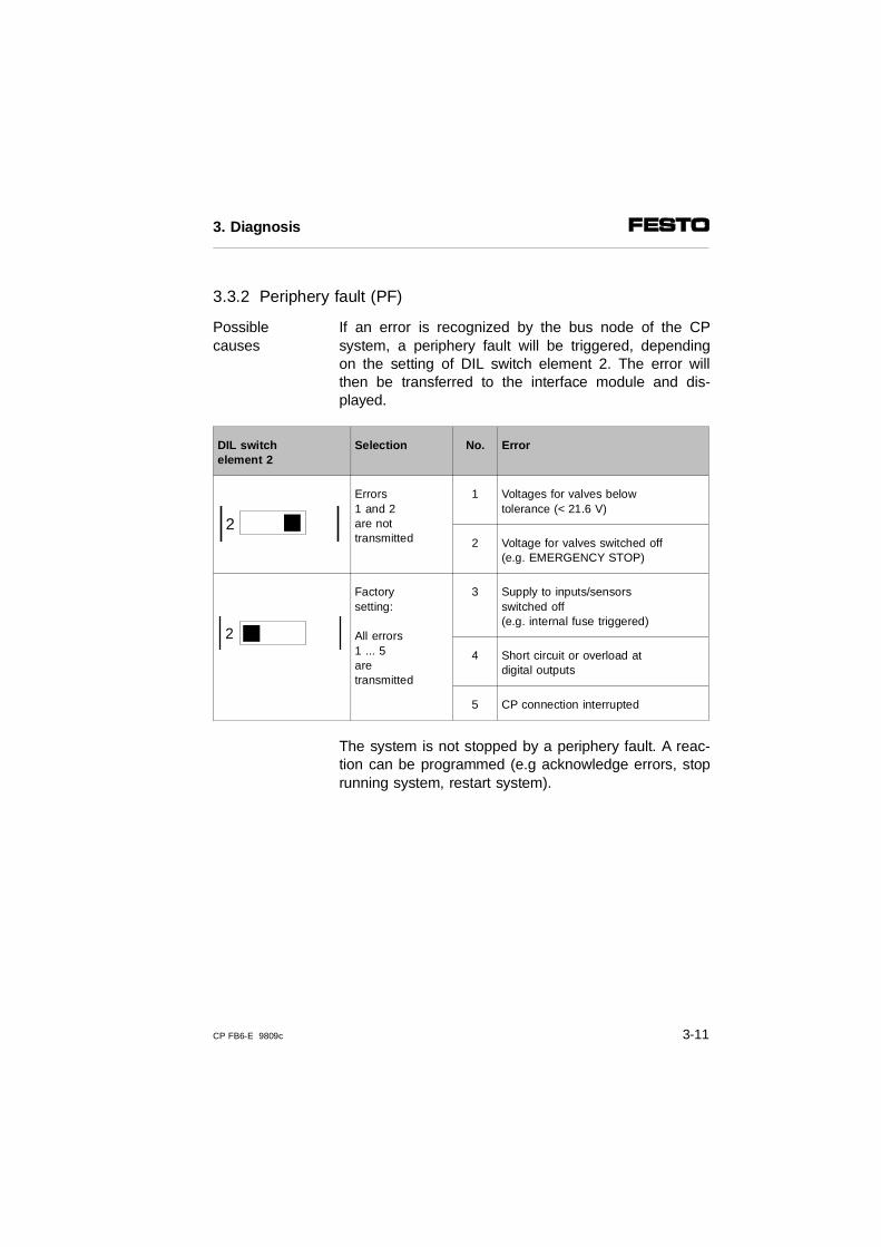
3.3.2 Periphery fault (PF)
If an error is recognized by the bus node of the CPsystem, a periphery fault will be triggered, dependingon the setting of DIL switch element 2. The error willthen be transferred to the interface module and dis-played.
Possiblecauses
DIL switchelement 2
Selection No. Error
Errors 1 and 2are nottransmitted
1 Voltages for valves belowtolerance (< 21.6 V)
2 Voltage for valves switched off(e.g. EMERGENCY STOP)
Factorysetting:
All errors1 ... 5are transmitted
3 Supply to inputs/sensorsswitched off (e.g. internal fuse triggered)
4 Short circuit or overload atdigital outputs
5 CP connection interrupted
The system is not stopped by a periphery fault. A reac-tion can be programmed (e.g acknowledge errors, stoprunning system, restart system).
2
2
3. Diagnosis
CP FB6-E 9809c 3-11
3.4 Reaction to faults in the control system
Reaction of the system to faults
of the INTERBUS in the control system
In the case of field busfaults due to failure of thefield bus signal orinterruption of the field bus cable all outputs(valves and electrical outputs) will be switchedoff after25 ms.
With programmed INTERBUSreset or processor reset, all outputs(valves and electrical outputs) on theCP system will be switched off.
Please note.- unilaterally-actuated valves move
to the basic position- double solenoid valves remain in
the current position
3. Diagnosis
3-12 CP FB6-E 9809c
Appendix A
Technical appendix
A. Technical appendix
CP FB6-E 9808c A-1
Contents
A. Technical appendix
A.1 Technical specifications of the field bus node CP FB6-E . . . . . A-3A.2 Index . . . . . . . . . . . . . . . . . . . . . . . . . . . . . . . . . . . . . . . . . . . . . . A-5
A. Technical appendix
A-2 CP FB6-E 9808c
A.1 Technical specifications of the field bus node CP FB6-E
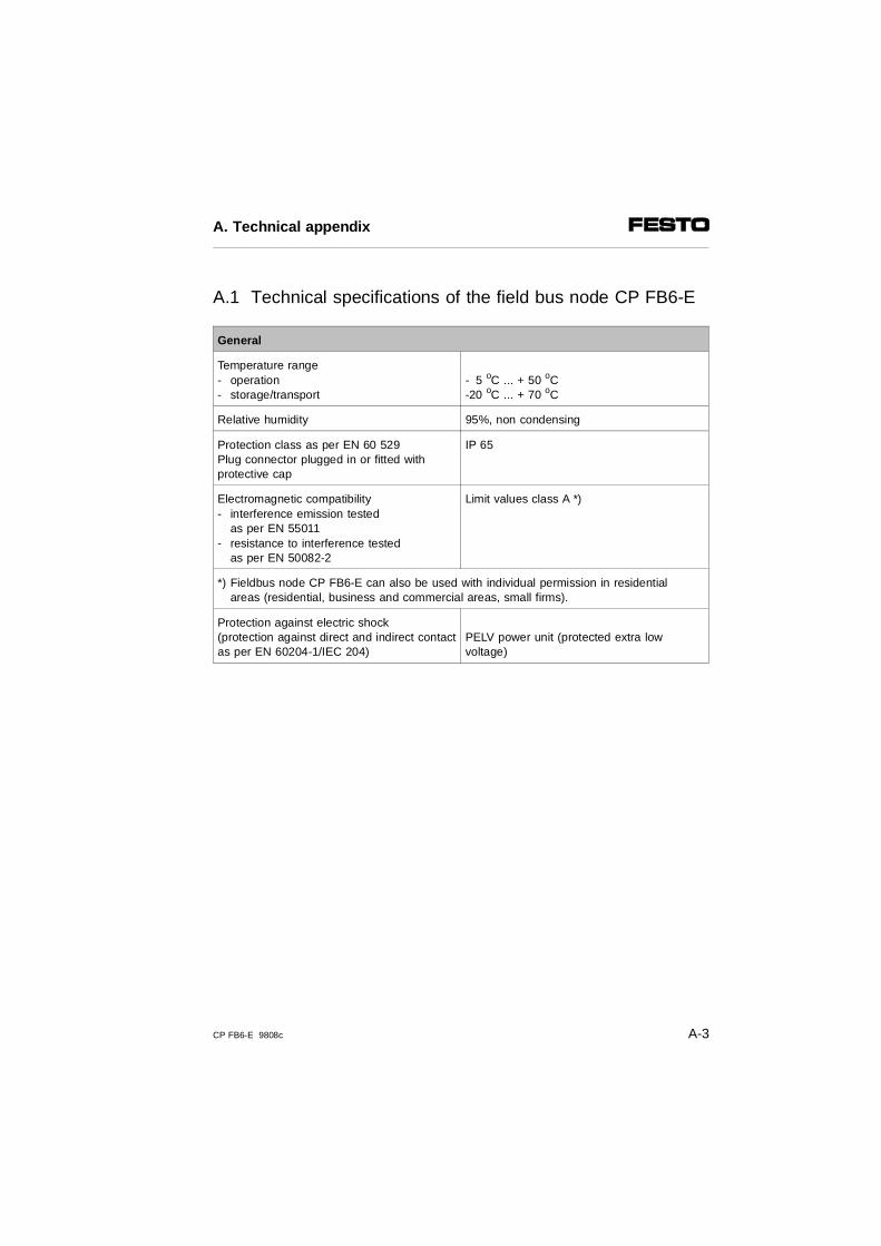
General
Temperature range- operation- storage/transport
- 5 oC ... + 50 oC-20 oC ... + 70 oC
Relative humidity 95%, non condensing
Protection class as per EN 60 529Plug connector plugged in or fitted with protective cap
IP 65
Electromagnetic compatibility- interference emission tested
as per EN 55011- resistance to interference tested
as per EN 50082-2
Limit values class A *)
*) Fieldbus node CP FB6-E can also be used with individual permission in residentialareas (residential, business and commercial areas, small firms).
Protection against electric shock (protection against direct and indirect contactas per EN 60204-1/IEC 204)
PELV power unit (protected extra low voltage)
A. Technical appendix
CP FB6-E 9808c A-3
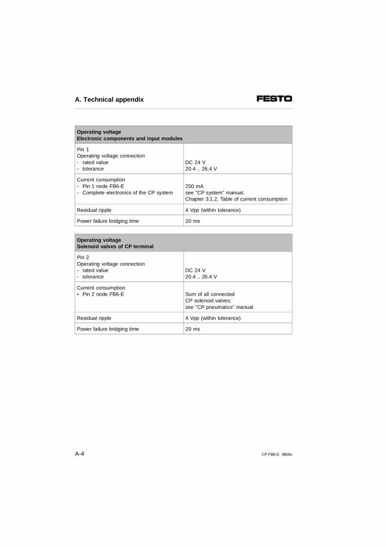
Operating voltage Electronic components and input modules
Pin 1Operating voltage connection- rated value - tolerance
DC 24 V20.4 .. 26.4 V
Current consumption- Pin 1 node FB6-E- Complete electronics of the CP system
250 mAsee "CP system" manual,Chapter 3.1.2, Table of current consumption
Residual ripple 4 Vpp (within tolerance)
Power failure bridging time 20 ms
Operating voltage Solenoid valves of CP terminal
Pin 2Operating voltage connection- rated value- tolerance
DC 24 V20.4 .. 26.4 V
Current consumption• Pin 2 node FB6-E Sum of all connected
CP solenoid valves;see "CP pneumatics" manual
Residual ripple 4 Vpp (within tolerance)
Power failure bridging time 20 ms
A. Technical appendix
A-4 CP FB6-E 9808c
A.2 Index
AAbbreviations
product-specific . . . . . . . . . . . . . . . . . . . . . . . . . . . IXAddress assignment . . . . . . . . . . . . . . . . . . . . . . . . 2-19Addressing
logical. . . . . . . . . . . . . . . . . . . . . . . . . . . . . . . . . 2-12manufacturer-specific. . . . . . . . . . . . . . . . . . . . . . 1-5physical . . . . . . . . . . . . . . . . . . . . . . . . . . . . . . . 2-15
Ascertaining the ID code . . . . . . . . . . . . . . . . . . . . . 2-13Ascertaining the process data channel bits. . . . . . . 2-13
BBus LEDs
diagnosis . . . . . . . . . . . . . . . . . . . . . . . . . . . . . . . 3-6Byte swap . . . . . . . . . . . . . . . . . . . . . . . . . . . . . . . . 2-21
CConfiguration list . . . . . . . . . . . . . . . . . . . . . . . . . . . . 2-4
creating . . . . . . . . . . . . . . . . . . . . . . . . . . . . . . . . 2-4Configuration run . . . . . . . . . . . . . . . . . . . . . . . . . . . 2-17Connecting
INTERBUS interface . . . . . . . . . . . . . . . . . . . . . . 1-6Connection variants . . . . . . . . . . . . . . . . . . . . . . . . . . 1-7CP system
operating voltage . . . . . . . . . . . . . . . . . . . . . . . . . 2-3preparing for operation on the INTERBUS . . . . . 2-3
A. Technical appendix
CP FB6-E 9808c A-5
DDesignated use . . . . . . . . . . . . . . . . . . . . . . . . . . . . . . VDiagnosis
bus LEDs . . . . . . . . . . . . . . . . . . . . . . . . . . . . . . . 3-6diagnostic register . . . . . . . . . . . . . . . . . . . . . . . 3-10operating voltage LEDs . . . . . . . . . . . . . . . . . . . . 3-5
EErrors
treatment . . . . . . . . . . . . . . . . . . . . . . . . . . . . . . 3-10
FFaults
field bus . . . . . . . . . . . . . . . . . . . . . . . . . . . . . . . 3-12PLC . . . . . . . . . . . . . . . . . . . . . . . . . . . . . . . . . . 3-12
Floating structure . . . . . . . . . . . . . . . . . . . . . . . . . . . . 1-8
IInformation on this manual. . . . . . . . . . . . . . . . . . . . . . VInstallation remote bus
connection . . . . . . . . . . . . . . . . . . . . . . . . . . . . . 1-14continuing. . . . . . . . . . . . . . . . . . . . . . . . . . . . . . 1-15incoming. . . . . . . . . . . . . . . . . . . . . . . . . . . . . . . 1-14non-floating . . . . . . . . . . . . . . . . . . . . . . . . . . . . 1-14
INTERBUSaddressing . . . . . . . . . . . . . . . . . . . . . . . . . 2-4, 2-19preparing . . . . . . . . . . . . . . . . . . . . . . . . . . . . . . . 2-4
INTERBUS interfaceconnecting . . . . . . . . . . . . . . . . . . . . . . . . . . . . . . 1-6
A. Technical appendix
A-6 CP FB6-E 9808c
LLEDs . . . . . . . . . . . . . . . . . . . . . . . . . . . . . . . . . . . . . 3-3
diagnosis . . . . . . . . . . . . . . . . . . . . . . . . . . 3-5 - 3-6Logical addressing . . . . . . . . . . . . . . . . . . . . . . . . . . 2-12
MManufacturer-specific addressing . . . . . . . . . . 1-5, 2-21
NNominal/actual configurations . . . . . . . . . . . . . . . . . . 2-4Non-floating remote bus . . . . . . . . . . . . . . . . . . . . . 1-11Non-floating structure. . . . . . . . . . . . . . . . . . . . . . . . . 1-9
OOperating status. . . . . . . . . . . . . . . . . . . . . . . . . . . . . 3-4Operating voltage
CP system . . . . . . . . . . . . . . . . . . . . . . . . . . . . . . 2-3
PPhysical addresses
calculating . . . . . . . . . . . . . . . . . . . . . . . . . . . . . 2-16Physical addressing . . . . . . . . . . . . . . . . . . . . . . . . . 2-15Pictograms . . . . . . . . . . . . . . . . . . . . . . . . . . . . . . . . . VIIPOWER LEDs
diagnosis . . . . . . . . . . . . . . . . . . . . . . . . . . . . . . . 3-5
A. Technical appendix
CP FB6-E 9808c A-7
RRemote bus
connection . . . . . . . . . . . . . . . . . . . . . . . . . . . . . 1-10floating . . . . . . . . . . . . . . . . . . . . . . . . . . . . . . . . 1-10incoming. . . . . . . . . . . . . . . . . . . . . . . . . . . . . . . 1-12
Remote field buscontinuing. . . . . . . . . . . . . . . . . . . . . . . . . . . . . . 1-13
SSAVE
string assignment. . . . . . . . . . . . . . . . . . . . . . . . . 2-3Screening/shielding variants . . . . . . . . . . . . . . . . . . . 1-7Siemens
settings. . . . . . . . . . . . . . . . . . . . . . . . . . . . . 1-4, 2-3String assignment
saving. . . . . . . . . . . . . . . . . . . . . . . . . . . . . . . . . . 2-3Switching status
valves . . . . . . . . . . . . . . . . . . . . . . . . . . . . . . . . . . 3-8
TTarget group . . . . . . . . . . . . . . . . . . . . . . . . . . . . . . . . . VTechnical specifications . . . . . . . . . . . . . . . . . . . . . . A-3Test routine for valves . . . . . . . . . . . . . . . . . . . . . . . . 3-8
UUser instructions . . . . . . . . . . . . . . . . . . . . . . . . . . . . . VI
A. Technical appendix
A-8 CP FB6-E 9808c
![Profibus PA Fieldbus Display [ Revision 2 ] and Fieldbus ... Instruments... · Profibus PA Fieldbus Display [ Revision 2 ] and Fieldbus Indicator Fieldbus Interface Guide. ... Siemens](https://img.dokumen.tips/doc/110x75/5b2fe38e7f8b9ae16e8da83d/profibus-pa-fieldbus-display-revision-2-and-fieldbus-instruments.jpg)