Embed Size (px)
Citation preview

COMMUNICATIONSMANUAL
EVO - Microprocessor Controlled Float Battery Charger
EVO AT SERIES BATTERY CHARGER
AT SERIES BATTERY CHARGER
EEEVVVOOO AAATTT SSSEEERRRIIIEEESSS BBBAAATTTTTTEEERRRYYY CCCHHHAAARRRGGGEEERRR
P R O D U C T
JA5011-54
A


NOTICE
! WARNING

iiAT SERIES BATTERY CHARGER
Table of Contents - ATevo
TABLE OF CONTENTS1. INTRODUCTION . . . . . . . . . . . . . . . . . . . . . . . . . . . . . . . . . . . . . . . . . . . . . . . . . . . . . 1
1.1 Overview . . . . . . . . . . . . . . . . . . . . . . . . . . . . . . . . . . . . . . . . . . . 2
2. PROTOCOLS . . . . . . . . . . . . . . . . . . . . . . . . . . . . . . . . . . . . . . . . . . . . . . . . . . . . . . . .32.1 Modbus Overview. . . . . . . . . . . . . . . . . . . . . . . . . . . . . . . . . . . . 42.2 DNP3 Overview . . . . . . . . . . . . . . . . . . . . . . . . . . . . . . . . . . . . . 5
3. HARDWARE . . . . . . . . . . . . . . . . . . . . . . . . . . . . . . . . . . . . . . . . . . . . . . . . . . . . . . . . 73.1 Serial Communications Adapter . . . . . . . . . . . . . . . . . . . . . . . 8
3.1.1 Serial Communications Adapter . . . . . . . . . . . . . . . . . . . . . . . . . . . .83.1.2 RS-232 . . . . . . . . . . . . . . . . . . . . . . . . . . . . . . . . . . . . . . . . . . . . . .93.1.3 3-Wire RS-232 Connections . . . . . . . . . . . . . . . . . . . . . . . . . . . . . . .93.1.4 5-Wire RS-232 Connections . . . . . . . . . . . . . . . . . . . . . . . . . . . . . .103.1.5 RS-485 . . . . . . . . . . . . . . . . . . . . . . . . . . . . . . . . . . . . . . . . . . . . .113.1.6 2-Wire RS-485 Connections . . . . . . . . . . . . . . . . . . . . . . . . . . . . . .133.1.7 Optional Serial Fiber Modems . . . . . . . . . . . . . . . . . . . . . . . . . . . .14
3.2 Ethernet Communications Adapter Option . . . . . . . . . . . . . 143.2.1 Ethernet Communication Adapter Installation . . . . . . . . . . . . . . . . .143.2.2 Ethernet . . . . . . . . . . . . . . . . . . . . . . . . . . . . . . . . . . . . . . . . . . . .163.2.3 Ethernet Connections . . . . . . . . . . . . . . . . . . . . . . . . . . . . . . . . . .163.2.4 Optional Fiber Ethernet Interface . . . . . . . . . . . . . . . . . . . . . . . . . .16
4. CONFIGURATION . . . . . . . . . . . . . . . . . . . . . . . . . . . . . . . . . . . . . . . . . . . . . . . . . . 174.0 Confi guration . . . . . . . . . . . . . . . . . . . . . . . . . . . . . . . . . . . . . . 184.1 Serial Communications Adapter Confi guration . . . . . . . . . . 18
4.1.1 Assigning the PORT Protocol . . . . . . . . . . . . . . . . . . . . . . . . . . . . . .194.1.2 Changing the Common PORT Communication Parameters . . . . . . . .204.1.3 Changing the Modbus Serial PORT Communication Parameters . . . .264.1.4 Changing the DNP3 Serial PORT Communication Parameters . . . . .27
iiiAT SERIES BATTERY CHARGER
Table of Contents - ATevo
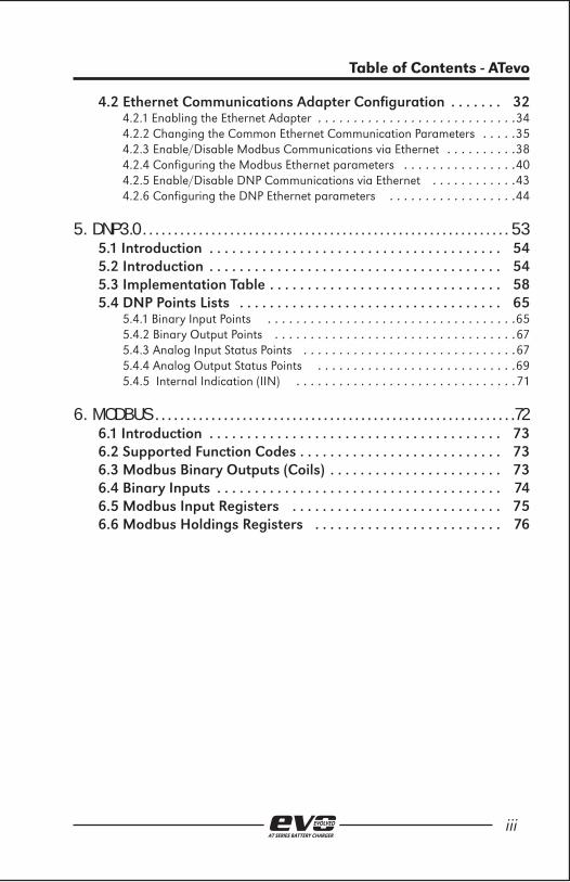
4.2 Ethernet Communications Adapter Confi guration . . . . . . . 324.2.1 Enabling the Ethernet Adapter . . . . . . . . . . . . . . . . . . . . . . . . . . . .344.2.2 Changing the Common Ethernet Communication Parameters . . . . .354.2.3 Enable/Disable Modbus Communications via Ethernet . . . . . . . . . .384.2.4 Configuring the Modbus Ethernet parameters . . . . . . . . . . . . . . . .404.2.5 Enable/Disable DNP Communications via Ethernet . . . . . . . . . . . .434.2.6 Configuring the DNP Ethernet parameters . . . . . . . . . . . . . . . . . .44
5. DNP3.0 . . . . . . . . . . . . . . . . . . . . . . . . . . . . . . . . . . . . . . . . . . . . . . . . . . . . . . . . . . . 535.1 Introduction . . . . . . . . . . . . . . . . . . . . . . . . . . . . . . . . . . . . . . . 545.2 Introduction . . . . . . . . . . . . . . . . . . . . . . . . . . . . . . . . . . . . . . . 545.3 Implementation Table . . . . . . . . . . . . . . . . . . . . . . . . . . . . . . . 585.4 DNP Points Lists . . . . . . . . . . . . . . . . . . . . . . . . . . . . . . . . . . . 65
5.4.1 Binary Input Points . . . . . . . . . . . . . . . . . . . . . . . . . . . . . . . . . . .655.4.2 Binary Output Points . . . . . . . . . . . . . . . . . . . . . . . . . . . . . . . . . .675.4.3 Analog Input Status Points . . . . . . . . . . . . . . . . . . . . . . . . . . . . . .675.4.4 Analog Output Status Points . . . . . . . . . . . . . . . . . . . . . . . . . . . .695.4.5 Internal Indication (IIN) . . . . . . . . . . . . . . . . . . . . . . . . . . . . . . .71
6. MODBUS . . . . . . . . . . . . . . . . . . . . . . . . . . . . . . . . . . . . . . . . . . . . . . . . . . . . . . . . . .726.1 Introduction . . . . . . . . . . . . . . . . . . . . . . . . . . . . . . . . . . . . . . . 736.2 Supported Function Codes . . . . . . . . . . . . . . . . . . . . . . . . . . . 736.3 Modbus Binary Outputs (Coils) . . . . . . . . . . . . . . . . . . . . . . . 736.4 Binary Inputs . . . . . . . . . . . . . . . . . . . . . . . . . . . . . . . . . . . . . . 746.5 Modbus Input Registers . . . . . . . . . . . . . . . . . . . . . . . . . . . . 756.6 Modbus Holdings Registers . . . . . . . . . . . . . . . . . . . . . . . . . 76


1. INTRODUCTION
AT SERIES BATTERY CHARGER

2AT SERIES BATTERY CHARGER
1 Receiving & Mounting the AT SERIES EVO
1.1 OverviewThe EVO Communications options allow users to remotely observe any status or perform any function that is accessible at the charger’s front panel display. Two communications option boards are available, the Serial Communications Adapter and the Ethernet Communications Adapter.
The Serial Communication option supports 3-wire or 5-wire RS-232 and 2-wire or 4-wire RS-485 connections at BAUD rates from 9600 to 115.2K. The Ethernet Communications option supports standard RJ-45 10/100 Mbps copper Ethernet connections. The communications options support DNP3 Level 2 and Modbus protocols..

2. PROTOCOLS
AT SERIES BATTERY CHARGER

4AT SERIES BATTERY CHARGER
2 Protocols
2.1 Modbus OverviewThe communications options can be setup to communicate on standard Modbus networks using either of two transmission modes: ASCII (American Standard Code for Information Interchange) or RTU (Remote Terminal Unit). The advantage of ASCII mode is that it allows less strict serial timing requirements without causing communication errors. The advantage of RTU mode is that it allows more data to be transmitted with less overhead than ASCII mode for higher throughput.
Modbus ASCII mode supports the following serial settings:
• No parity, 7 data bits, 2 stop bits
• Even parity, 7 data bits, 1 stop bit
• Odd parity, 7 data bits, 1 stop bit
Modbus RTU mode supports the following serial settings:
• No parity, 8 data bits, 1 stop bits
• No parity, 8 data bits, 2 stop bits
• Even parity, 8 data bits, 1 stop bit
• Odd parity, 8 data bits, 1 stop bit
Refer to Section 6.0 for more details about the Modbus protocol and the EVO Modbus Register set.

5AT SERIES BATTERY CHARGER
2 Protocols
2.2 DNP3 OverviewThe communications options support DNP3 Level 2. This implementation of DNP3 meets Level 2 conformance and supports change events with unsolicited messaging.
The DNP3 Level 2 protocol supports the following serial settings:
• No parity, 8 data bits, 1 stop bit
• No parity, 8 data bits, 2 stop bits
• Even parity, 8 data bits, 1 stop bit
• Odd parity, 8 data bits, 1 stop bit
Refer to Section 5.0 for more details about the DNP3 protocol and the EVO DNP3 Point list.


3. HARDWARE
AT SERIES BATTERY CHARGER

8AT SERIES BATTERY CHARGER
3 Hardware
3.1 Serial Communications Adapter The EVO can support up to three (3) Serial Communication Adapters. Each Serial Communications Adapter will support connections to either RS-232 or RS-485 networks. The Serial Adapter hardware must be confi gured correctly before connecting to the network.
3.1.1 Serial Communications Adapter Each Serial Adapter is confi gured independently and can be set up to connect to different network types.
Serial Communication Adapters can be plugged in to “PORT 1” (P10), “PORT 2” (P11), and/or “PORT 3” (P12) located along the left side of the Main Control Board. Both PORT 2 (P11) and PORT 3 (P12) will support DNP3 and Modbus protocols
To install a Serial Communications Adapter:• Open (turn off) both the AC Input (CB1) and DC Output (CB2)
circuit breakers.
• Wait for the charger voltage to ramp down (the display will go blank and all LEDs will be off).
• Open the charger front door.
• Remove the ground connection from the lower left corner of the Main Control Board.
• Carefully disengage the Main Control Board from the standoffs

9AT SERIES BATTERY CHARGER
3 Hardware
on the left side of the Main Control Board.
• Make sure you correctly confi gured the Serial Communication Adapter Boards hardware settings (see sections 3.1.2 – 3.1.7).
• Locate the Serial Communication Adapter connection ports (P10, P11, & P12) along the left side of the Main Control Board attached to the door.
• Carefully slide the socket (P1) of the Serial Communications Adapter on to the pins of one of the connection ports (P10, P11,P12) of the Main Control Board (for Modbus or DNP3, use P11 or P12)
• You will need to hold the Serial Communications Adapter at an angle to clear the stand-off on the door.
• Once the Serial Communications Adapter socket is fully engaged on to the Main Control Board header pins, line up the hole on the Serial Connection Board with the plastic stand-off pin.
• Press down on the Serial Communications Adapter and the Main Control Board to lock them on to the stand-offs.
• Replace the ground connection on the bottom left hand side of the Main Control Board.
• Make note of which PORT (2 or 3 for Modbus or DNP3) you connect the Serial Communications Adapter to.
• Close the charger’s door.
• Close (turn on) the AC Input Breaker (CB1) and then close the DC Output Breaker (CB2).
• The Serial Communication Adapter hardware is now installed.
• Refer to the PORT SETUP instructions in the protocol section to assign a protocol to the Serial Communication Adapter and to confi gure the communication parameters (baud rate, parity, etc).
3.1.2 RS-232 RS-232 is a standard for serial transmission of data. The RS-232 standard was commonly used in computer serial ports for connections to modem, mice, and printers. RS-232 only permits two devices to be connected together, has a limited cable distance, and is susceptible to electrical noise.
3.1.3 3-Wire RS-232 Connections To confi gure the Serial Adapter for 3-Wire RS-232 connections:

10AT SERIES BATTERY CHARGER
3 Hardware
• P3, “MEDIA” must be set to “232”
• P6 and P7, “# WIRES” must be set to “4W”
• P2, “RXCTRL” must be set to “ON”
• P4 and P5, “485-TERM” must be set to “OFF”
To connect the Serial Adapter to the RS-232 network:
• Wire RXD (TB1-1) to the RS-232 network TXD
• Wire TXD (TB1-2) to the RS-232 network RXD
• Wire GND (TB1-5) to the RS-232 network COM
3.1.4 5-Wire RS-232 Connections To confi gure the Serial Adapter for 5-Wire RS-232 connections:

11AT SERIES BATTERY CHARGER
3 Hardware
• P3, “MEDIA” must be set to “232”
• P6 and P7, “# WIRES” must be set to “4W”
• P2, “RXCTRL” must be set to “ON”
• P4 and P5, “485-TERM” must be set to “OFF”
To connect the Serial Adapter to the RS-232 network:
• Wire RXD (TB1-1) to the RS-232 network TXD
• Wire TXD (TB1-2) to the RS-232 network RXD
• Wire CTS (TB1-3) to the RS-232 network RTS
• Wire RTS (TB1-4) to the RS-232 network CTS
• Wire GND (TB1-5) to the RS-232 network COM
3.1.5 RS-485 RS-485 is a standard defi ning electrical characteristics of drivers and receivers for use in balanced digital multipoint systems. RS-485 networks can be used effectively over long distances in electrically noisy industrial environments. Multiple devices may be connected to the same network.
Some RS-485 networks may require terminating resistors at both

12AT SERIES BATTERY CHARGER
3 Hardware
ends of the serial network. The decision of whether or not to use termination resistors should be based on the BAUD rate, the cable distance, and the type of cable being used to build the network. In most cases for BAUD rates less than 19.2K, terminating resistors are not required. If termination resistors are used, the network must be designed with the appropriate biasing resistors to ensure reliable communications.
The biasing resistors are responsible for ensuring that the network remains in the idle state when all drivers are tri-stated. In order to guarantee that the receivers remain in a known state, +/- 200mV must always be maintained across the (+) and (-) or (A) and (B) RS-485 inputs. The use of termination resistors requires a signifi cantly lower value of biasing resistors which results in greater dc loading of the network.
Network design and biasing resistor calculations depend on the number of nodes on the network, the type of drivers and receivers on the network, and any biasing already designed into other devices sharing the network. As a result, whether or not use termination resistors and biasing resistor calculation is beyond the scope of this manual. For more information on biasing and termination details see the following ref-erences:
1. EIA/TIA-485 StandardTelecommunication Industry Associationhttp://www.tiaonline.org/standards/catalog/
2. RS-422/RS-485 Application NoteCopyright: B&B Electronics http://www.bb-elec.com/tech_articles/rs422_485_app_note/table_of_contents.asp http://www.ATSeries.net/PDFs/RS422+485AppNote.pdf
The Serial Communication Adapter board has confi gurable 120 ohm termination resistors. Jumper P4 and P5 enables or disables the terminating resistors.

13AT SERIES BATTERY CHARGER
3 Hardware
3.1.6 2-Wire RS-485 Connections To confi gure the Serial Adapter for 2-Wire RS-485 connections:
• P3, “MEDIA” must be set to “485”
• P6 and P7, “# WIRES” must be set to “2W”
• P2, “RXCTRL” must be set to “TXE”
• P4 and P5, “485-TERM” should be set to “OFF”
NOTE:If you want to utilize the on-board termination resistor located on the Serial Adapter, set “P5” to the “ON” position. Termination resistors should only be placed on the extreme ends of the network (2 de-vices only). In addition, the network must be biased correctly or the termination resistors may cause communication errors.
To connect the Serial Adapter to the RS-485 network:
• Wire A- (TB1-1) to the RS-485 network A-
• Wire B+ (TB1-3) to the RS-485 network B+
• Wire GND (TB1-5) to the RS-485 network COM

14AT SERIES BATTERY CHARGER
3 Hardware
NOTE:P6 when set to “2W” connects TB1-1 to TB1-2. P7 when set to “2W” connects TB1-3 to TB1-4.
3.1.7 Optional Serial Fiber Modems Several optional fi ber optics to serial converters are available for EVO Chargers. When ordered, this option (EJ5230-##) will be installed in the charger at the factory, and will allow direct connection of fi ber connections compatible with standard “B&B” and “DYMEC” type converters. Please refer to the following supplemental documentation for the available Fiber Optics Interface options.
EJ5230-0X “B&B” Fiber Optics Interface for EVO
EJ5230-1X“DYMEC” RS485 Fiber Optics Interface for EVO
EJ5230-2X“DYMEC” RS232 Fiber Optics Interface for EVO
3.2 Ethernet Communications Adapter Option The EVO can support one (1) Ethernet Communication Adapter. The Ethernet Communications Adapter contains a standard RJ-45 connector and will support copper 10/100 Mbps Ethernet connections. The Ethernet Communication Adapter will support multiple protocols (Modbus and DNP3) simultaneously.
3.2.1 Ethernet Communication Adapter Installation The Ethernet Communications Option plugs in to the “Ethernet” port (P13), located near the bottom of the left side of the Main Control Board.

15AT SERIES BATTERY CHARGER
3 Hardware
To install an Ethernet Communications Adapter:
• Open (turn off) both the AC Input (CB1) and DC Output (CB2) circuit breakers.
• Wait for the charger voltage to ramp down (the display will go blank and all LEDs will be off).
• Open the charger front door.
• Remove the ground connection from the lower left corner of the Main Control Board.
• Carefully disengage the Main Control Board from the standoffs on the left side of the Main Control Board.
• Locate the Ethernet Communication Adapter connection port (P13) near the bottom along the left side of the Main Control Board attached to the door.
• Carefully slide the socket (P1) of the Ethernet Communications Adapter on to the pins of the connection port (P13) of the Main Control Board.
• You will need to hold the Ethernet Communications Adapter at an angle to clear the stand-offs on the door.
• Once the Ethernet Communications Adapter socket is fully engaged on to the Main Control Board header pins, line up the holes on the Ethernet Connection Board with the plastic stand-off pins.
• Press down on the Ethernet Communications Adapter and the Main Control Board to lock them on to the stand-offs.

16AT SERIES BATTERY CHARGER
3 Hardware
• Replace the ground connection on the bottom left hand side of the Main Control Board.
• Close the charger’s door.
• Close (turn on) the AC Input Breaker (CB1) and then close the DC Output Breaker (CB2).
• The Ethernet Communication Adapter hardware is now installed.
• Refer to the Ethernet Communications Confi guration to assign a protocol to the Serial Communication Adapter and to confi gure the communication parameters (IP address, Netmask, Gateway, etc).
3.2.2 Ethernet Ethernet is a family of computer networking technologies commonly used in local area networks (LANs). Several variants of Ethernet are available and newer variants typically use copper twisted pair or fi ber optic links in conjunction with hubs or switch to form the network. Ethernet permits a large number of devices to be interconnected and allows the devices to communicate via multiple protocols concurrently.
3.2.3 Ethernet Connections The EVO can be connected to a 10/100 Mbps Ethernet network with a standard Ethernet RJ-45 cable. Plug one end of the cable into J1 of the Ethernet Adapter and the other end into an Ethernet hub, switch or directly into the SCADA master.
3.2.4 Optional Fiber Ethernet Interface Although Ethernet interfaces are standardized, several variants of Ethernet over fi ber exist. The variants are based on different data rates, fi ber type, wavelength, and connector types. At the time of the writing of this manual, over 75 know variants exist.
The EVO Optional Fiber Ethernet Interface can be confi gured to accommodate most if not all of these variants. Due to the vast number of the variants and the continuous additions of new ones, the specifi c offerings and capabilities needed to interface to your fi ber Ethernet network need to be verifi ed with your EVO distributer. Contact the supplier of your EVO for the latest information on the fi ber Ethernet interfaces supported.

4. CONFIGURATION
AT SERIES BATTERY CHARGER

18AT SERIES BATTERY CHARGER
4 Confi guration
4.0 Confi guration Confi guration of EVO Serial Communication Adapter and the Ethernet Communication Adapter are performed by accessing the EVO Main Menu. The Serial Communication and Ethernet Communications Adapter settings appear when the “COMMUNICATION” icon is selected. For information on how to access the EVO Main Menu and select icons see Section 5.0 of the “EVO Operation & Service Instructions” manual.
4.1 Serial Communications Adapter Confi guration Before confi guring EVO Serial Communication Adapters, refer to Section 3.1 to make sure the hardware jumper settings on the serial communication adapter cards are correct for your application. To change or verify the Serial Communications Adapter Confi guration:
• Press the MENU button. The menu selection icons will appear on the display.
• Use the UP, DOWN, LEFT and RIGHT buttons to navigate to the COMMUNICATION icon. Note that there are multiple pages of icons, observe the arrow(s) at the top right of the display to de-termine which direction to scroll to view the next page of icons.
• Press the EDIT/ENTER button when the COMMUNICATION icon is selected (shown in inverse video).
• The EVO COMMUNICATION screen will appear which will allow you to select a PORT and change any of the confi guration settings for that PORT.

19AT SERIES BATTERY CHARGER
4 Confi guration
NOTE:You must have a Serial Communications Adapter installed in the associated PORT in order for that port to be operational. Any of the PORTs without a Serial Communications Adapter must be set up as “Unconfi gured” (appears as “none”). See Section 3.1.1 for details on installed Communication Adapters.
4.1.1 Assigning the PORT Protocol When confi guring a PORT, always set the protocol fi rst. If a serial PORT is not assigned a protocol, “(none)” will appear next to the PORT name. If the Serial PORT is already assigned a protocol, see Section 4.1.2 for instructions on how to change the PORT confi guration. The remaining parameters of the PORT con-fi guration will be different and depends on the protocol selected. To assign a protocol to a serial PORT that is not presently assigned a protocol:
• Follow the instructions in Section 4.1 to navigate to and highlight the serial PORT you want to change.
• Press the EDIT/ENTER button. If the serial PORT has not been assigned a protocol, “(none)” will appear after PORT selection, and the following message will appear.

20AT SERIES BATTERY CHARGER
4 Confi guration
• If this message does appear, press any button to advance to the Protocol Selection screen, otherwise refer to Section 4.1.2 for instruction on how to change the PORT parameters.
• Use the UP or DOWN button to navigate through the protocol choices and stop when the desired protocol is being displayed.
• Press the EDIT/ENTER button to confi gure the serial PORT to use the selected protocol.
4.1.2 Changing the Common PORT Communication Parameters
Several of the serial PORT confi guration parameters are used by all protocols, other parameters are only used by specifi c protocols. This section specifi es the confi guration of the common parameters that are used by all protocols. To change these parameters:

21AT SERIES BATTERY CHARGER
4 Confi guration
NOTE:The PORT must have a protocol assigned before proceeding. See Section 4.1.1 for instructions on how to assign a protocol to an unconfi gured PORT.
• Follow the instructions in Section 4.1 to navigate to and highlight the serial PORT you want to change.
• Use the UP, DOWN, LEFT and RIGHT buttons to navigate to the serial PORT (2, or 3) you want to change, and press the EDIT/ENTER button.
• To change the protocol, press the UP or DOWN buttons to navigate to the “Protocol:” parameter and press the EDIT/ENTER button.
• Use the UP or DOWN button to navigate through the protocol choices and stop when the desired protocol is selected.
22AT SERIES BATTERY CHARGER
4 Confi guration
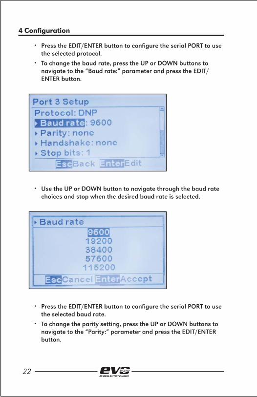
• Press the EDIT/ENTER button to confi gure the serial PORT to use the selected protocol.
• To change the baud rate, press the UP or DOWN buttons to navigate to the “Baud rate:” parameter and press the EDIT/ENTER button.
• Use the UP or DOWN button to navigate through the baud rate choices and stop when the desired baud rate is selected.
• Press the EDIT/ENTER button to confi gure the serial PORT to use the selected baud rate.
• To change the parity setting, press the UP or DOWN buttons to navigate to the “Parity:” parameter and press the EDIT/ENTER button.
23AT SERIES BATTERY CHARGER
4 Confi guration
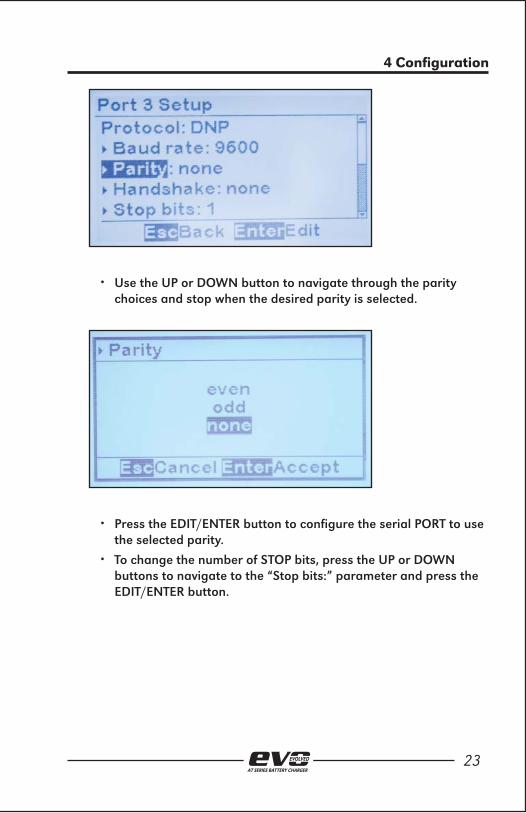
• Use the UP or DOWN button to navigate through the parity choices and stop when the desired parity is selected.
• Press the EDIT/ENTER button to confi gure the serial PORT to use the selected parity.
• To change the number of STOP bits, press the UP or DOWN buttons to navigate to the “Stop bits:” parameter and press the EDIT/ENTER button.

24AT SERIES BATTERY CHARGER
4 Confi guration
• Use the UP or DOWN button to change the number of STOP bits.
• Press the EDIT/ENTER button to confi gure the serial PORT to use the number of STOP bits displayed.
• To change the handshake setting, press the UP or DOWN buttons to navigate to the “Handshake:” parameter and press the EDIT/ENTER button.

25AT SERIES BATTERY CHARGER
4 Confi guration
NOTE: Handshaking is never used in RS-485 applications and is rarely used in RS-232 applications. Handshaking was typically used many years ago when communicating through older dial-up phone modems. It is strongly suggested that this parameter be set to “none”.
• Use the UP or DOWN button to navigate through the handshake choices and stop when the desired setting is selected. The recommended setting is “none”.
• Press the EDIT/ENTER button to confi gure the serial PORT to use the selected handshake setting

26AT SERIES BATTERY CHARGER
4 Confi guration
4.1.3 Changing the Modbus Serial PORT Communication Parameters
Several of the serial PORT confi guration parameters are used by all protocols, these parameters are described in Section 4.1.2. In addition to the common parameters listed in Section 4.1.2, the Modbus protocols require a unique device ID address in the range of 1 to 247. To change the Modbus ID address:
• The PORT must have Modbus assigned as the protocol before proceeding. See Section 4.1.1 for instructions on how to assign an unused PORT to use Modbus protocol, or Section 4.1.2 for instruction on how to change a confi gured PORT to use Modbus protocol.
• Follow the instructions in Section 4.1 to navigate to and highlight the serial PORT you want to change.
• To change the Modbus ID address, press the UP or DOWN buttons to navigate to the “Address:” parameter and press the EDIT/ENTER button.
• Press the LEFT or RIGHT buttons to select the digit to change. Press the UP or DOWN button to adjust the address.

27AT SERIES BATTERY CHARGER
4 Confi guration
• Press the EDIT/ENTER button to confi gure the serial PORT Modbus address
4.1.4 Changing the DNP3 Serial PORT Communication Parameters
Several of the serial PORT confi guration parameters are used by all protocols, these parameters are described in Section 4.1.2. In addition to the common parameters listed in Section 4.1.2, the DNP3 protocol requires a unique device source address in the range of 1 to 65535 and specifi c confi guration parameters associated with the unsolicited response feature. To change theses DNP3 parameters:
• The PORT must have DNP assigned as the protocol before proceeding. See Section 4.1.1 for instructions on how to assign an unused PORT to use the DNP protocol, or Section 4.1.2 for instruction on how to change a confi gured PORT to use the DNP protocol.
• Follow the instructions in Section 4.1 to navigate to and highlight the serial PORT you want to change.
• To change the DNP3 source address, press the UP or DOWN buttons to navigate to the “Address:” parameter and press the EDIT/ENTER button.

28AT SERIES BATTERY CHARGER
4 Confi guration
• Press the LEFT or RIGHT buttons to select the digit to change. Press the UP or DOWN button to adjust the address.
• Press the EDIT/ENTER button to confi gure the displayed serial PORT DNP source address.
• To enable or disable DNP unsolicited messages, press the UP or DOWN buttons to navigate to the “Unsolicited:” parameter and press the EDIT/ENTER button.
NOTE: Unsolicited messages are rarely used in DNP. Before enabling unsolicited messages check with the network administrator to make sure the network is capable of supporting the DNP unsolicited messages.

29AT SERIES BATTERY CHARGER
4 Confi guration
• Press the UP or DOWN button to select enable or disable unsolicited messaging.
• Press the EDIT/ENTER button to confi gure the serial DNP3 PORT unsolicited messaging.
NOTE: The remaining DNP parameters are only used when DNP unsolicited messages are enabled. If unsolicited messages are disabled, there is no need to confi gure the remaining DNP parameters.
• To change the DNP unsolicited response destination address, press the UP or DOWN buttons to navigate to the “Destination address:” parameter and press the EDIT/ENTER button.

30AT SERIES BATTERY CHARGER
4 Confi guration
• Press the LEFT or RIGHT buttons to select the digit to change. Press the UP or DOWN button to adjust the DNP unsolicited response destination address.
• Press the EDIT/ENTER button to confi gure the displayed serial PORT DNP unsolicited response destination address.
• To change the DNP unsolicited response acknowledgement timeout, press the UP or DOWN buttons to navigate to the “Timeout ms:” parameter and press the EDIT/ENTER button.

31AT SERIES BATTERY CHARGER
4 Confi guration
• Press the LEFT or RIGHT buttons to select the digit to change. Press the UP or DOWN button to adjust the timeout (value is in milliseconds).
• Press the EDIT/ENTER button to confi gure the displayed DNP unsolicited response acknowledgement timeout.
• To change the DNP number of unsolicited response retries, press the UP or DOWN buttons to navigate to the “Retries:” parameter and press the EDIT/ENTER button.

32AT SERIES BATTERY CHARGER
4 Confi guration
• Press the LEFT or RIGHT buttons to select the digit to change. Press the UP or DOWN button to adjust the number of DNP unsolicited response retries.
• Press the EDIT/ENTER button to confi gure the displayed number of DNP unsolicited response retries.
4.2 Ethernet Communications Adapter Confi guration
To change or verify the EVO Ethernet Communications Adapter Confi guration:
• Press the MENU button. The menu selection icons will appear on the display.
• Use the UP, DOWN, LEFT and RIGHT buttons to navigate to the COMMUNICATION icon. Note that there are multiple pages of

33AT SERIES BATTERY CHARGER
4 Confi guration
icons, observe the arrow(s) at the top right of the display to de-termine which direction to scroll to view the next page of icons.
• Press the EDIT/ENTER button when the COMMUNICATION icon is selected (shown in inverse video).
• The EVO COMMUNICATION screen will appear which will allow you to select the “Ethernet setup”. If “(none)” appears after the “Ethernet setup” selection, the Ethernet adapter will need to be enabled. See Section 4.2.1 for instructions on how to enable the Ethernet adapter.
NOTE: You must have an Ethernet Communications Adapter installed in order for Ethernet communications to be operational. If an Ethernet Communications Adapter is not installed, the Ethernet confi guration must be setup as “disabled” (appears as “none”). See Section 3.2.1 for details

34AT SERIES BATTERY CHARGER
4 Confi guration
on installed Communication Adapters.
4.2.1 Enabling the Ethernet Adapter The fi rst step in confi guring the Ethernet Adapter is to enable it. To enable the Ethernet Adapter:
• Follow the instructions in Section 4.2 to navigate to and highlight the “Ethernet setup” selection.
• Press the EDIT/ENTER button. If the Ethernet setup selection is not enabled, “(none)” will appear after PORT selection, and the following message will appear.
• Press The EDIT/ENTER button
• Use the UP or DOWN button to select “enable”.

35AT SERIES BATTERY CHARGER
4 Confi guration
• Press the EDIT/ENTER button to enable the Ethernet adapter. The Ethernet confi guration parameters will now appear on the display. Refer to Sections 4.2.2 - 4.2.6 for instruction on how to confi gure the remaining Ethernet parameters.
4.2.2 Changing the Common Ethernet Communication Parameters
Several of the Ethernet confi guration parameters are used by all protocols, other parameters are only used by specifi c protocols. This section specifi es the confi guration of the common parameters that are used by all protocols. To change these parameters:
• The Ethernet adapter must be enabled. See Section 4.2.1 for instructions on how to enable the Ethernet adapter.
• After selecting Ethernet setup from the COMMUNICATIONS Main Menu icon menu, the display should look similar to:
• Use the UP, DOWN, LEFT and RIGHT buttons to navigate to the “IP addr:” selection.

36AT SERIES BATTERY CHARGER
4 Confi guration
• Press the EDIT/ENTER button to edit the IP address.
• Press the LEFT and RIGHT buttons to scroll through each digit of the address and the UP or DOWN buttons to change the value of the address. Press the EDIT/ENTER button to store the new IP address.
• Use the UP, DOWN, LEFT and RIGHT buttons to navigate to the “Netmask:” selection.

37AT SERIES BATTERY CHARGER
4 Confi guration
• Press the EDIT/ENTER button to edit the Netmask.
• Press the LEFT and RIGHT buttons to scroll through each digit of the netmask and the UP or DOWN buttons to change the value of the netmask. Press the EDIT/ENTER button to store the new netmask.
• Use the UP, DOWN, LEFT and RIGHT buttons to navigate to the “Gateway:” selection.

38AT SERIES BATTERY CHARGER
4 Confi guration
• Press the EDIT/ENTER button to edit the gateway address.
• Press the LEFT and RIGHT buttons to scroll through each digit of the gateway address and the UP or DOWN buttons to change the value of the gateway address. Press the EDIT/ENTER button to store the new gateway address.
4.2.3 Enable/Disable Modbus Communications via Ethernet The EVO Ethernet adapter is capable of communicating via multiple protocols simultaneously. To enable or disable the Ethernet adapter to communicate via Modbus:
• Refer to Section 4.2.1 to make sure the Ethernet adapter is enabled.
• Refer to Section 4.2.2 to make sure the common Ethernet

39AT SERIES BATTERY CHARGER
4 Confi guration
parameters are confi gured and are correct (confi rm these settings with your network administrator).
• Navigate to the Ethernet setup and press the EDIT/ENTER button (see Section 4.2).
• Press the UP or DOWN buttons to navigate to and select the “Modbus:” parameter.
• Press the EDIT/ENTER button to modify the enable or disable status of the Modbus protocol.

40AT SERIES BATTERY CHARGER
4 Confi guration
• Press the UP or DOWN buttons to select either “enable” or “disable” Modbus Ethernet communication, and then press the EDIT/ENTER button.
4.2.4 Confi guring the Modbus Ethernet parameters Several of the Ethernet confi guration parameters are used by all protocols, these parameters are described in Section 4.2.2. In addition to the common parameters listed in Section 4.2.2, the Modbus Ethernet protocol requires confi guration of the following Modbus specifi c parameters. To change the Modbus specifi c Ethernet parameters:
• Refer to Section 4.2.1 to make sure the Ethernet adapter is enabled.
• Refer to Section 4.2.2 to make sure the common Ethernet parameters are confi gured and are correct (confi rm these settings with your network administrator).
• Refer to Section 4.2.3 to make sure the Modbus protocol is enabled on the Ethernet adapter.
• Navigate to the Ethernet setup and press the EDIT/ENTER button (see Section 4.2).

41AT SERIES BATTERY CHARGER
4 Confi guration
• To change the Modbus Ethernet Port number, press the UP or DOWN buttons to navigate to and select the “> Port:” parameter located directly after the “Modbus: enabled” selection.
• Press the EDIT/ENTER button to change the Modbus Ethernet Port setting.
NOTE: The default setting for the Modbus Ethernet Port is 502. It is highly recommended that this port number not be changed.
• Press the LEFT or RIGHT buttons to select the digit to change. Press the UP or DOWN button to adjust the Modbus Ethernet Port number.

42AT SERIES BATTERY CHARGER
4 Confi guration
• Press the EDIT/ENTER button to store the displayed Modbus Ethernet Port number.
• To change the Modbus ID address for the Ethernet interface, press the UP or DOWN buttons to navigate to and select the “> Address:” parameter located after the “Modbus: enabled” selection.
• Press the EDIT/ENTER button to change the Modbus slave ID address for the Ethernet interface.
• • Press the LEFT or RIGHT buttons to select the digit to change.
Press the UP or DOWN button to adjust the Modbus ID address for the Ethernet interface.

43AT SERIES BATTERY CHARGER
4 Confi guration
• Press the EDIT/ENTER button to store the displayed Modbus ID address for the Ethernet interface.
4.2.5 Enable/Disable DNP Communications via Ethernet The EVO Ethernet adapter is capable of communicating via multiple protocols simultaneously. To enable or disable the Ethernet adapter to communicate via DNP:
• Refer to Section 4.2.1 to make sure the Ethernet adapter is enabled.
• Refer to Section 4.2.2 to make sure the common Ethernet parameters are confi gured and are correct (confi rm these settings with your network administrator).
• Navigate to the Ethernet setup and press the EDIT/ENTER button (see Section 4.2).

44AT SERIES BATTERY CHARGER
4 Confi guration
• Press the UP or DOWN buttons to navigate to and select the “DNP:” parameter.
• Press the EDIT/ENTER button to modify the enable or disable status of the DNP protocol.
• Press the UP or DOWN buttons to select either “enable” or “disable” DNP Ethernet communication, and then press the EDIT/ENTER button.
4.2.6 Confi guring the DNP Ethernet parameters Several of the Ethernet confi guration parameters are used by all protocols, these parameters are described in Section 4.2.2. In addition to the common parameters listed in Section 4.2.2, the DNP Ethernet protocol requires confi guration of the following DNP specifi c

45AT SERIES BATTERY CHARGER
4 Confi guration
parameters. To change the DNP specifi c Ethernet parameters:
• Refer to Section 4.2.1 to make sure the Ethernet adapter is enabled.
• Refer to Section 4.2.2 to make sure the common Ethernet parameters are confi gured and are correct (confi rm these settings with your network administrator).
• Refer to Section 4.2.5 to make sure the DNP protocol is enabled on the Ethernet adapter.
• Navigate to the Ethernet setup and press the EDIT/ENTER button (see Section 4.2).
• To change the DNP Ethernet Port number, press the UP or DOWN buttons to navigate to and select the “> Port:” parameter located directly after the “DNP: enabled” selection.

46AT SERIES BATTERY CHARGER
4 Confi guration
• Press the EDIT/ENTER button to change the DNP Ethernet Port setting.
NOTE: The default setting for the DNP Ethernet Port is 20000. It is highly recommended that this port number not be changed.
• Press the LEFT or RIGHT buttons to select the digit to change. Press the UP or DOWN button to adjust the DNP Ethernet Port number.
• Press the EDIT/ENTER button to store the displayed DNP Ethernet Port number.
• To change the DNP source address for the Ethernet interface, press the UP or DOWN buttons to navigate to and select the “> Address:” parameter located after the “DNP: enabled” selection.

47AT SERIES BATTERY CHARGER
4 Confi guration
• Press the EDIT/ENTER button to change the DNP source address for the Ethernet interface.
• Press the LEFT or RIGHT buttons to select the digit to change. Press the UP or DOWN button to adjust the DNP source address for the Ethernet interface.
• Press the EDIT/ENTER button to store the displayed DNP source address for the Ethernet interface.
• To enable or disable DNP unsolicited messages for the Ethernet interface, press the UP or DOWN buttons to navigate to the “>Unsolicited:” parameter located after the “DNP: enabled” selection and press the EDIT/ENTER button.
NOTE: Unsolicited messages are rarely used in DNP. Before enabling unsolicited messages check with the network administrator to make sure the network is capable of supporting DNP unsolicited messages.

48AT SERIES BATTERY CHARGER
4 Confi guration
• Press the UP or DOWN button to select “enable” or “disable” unsolicited messaging.
• Press the EDIT/ENTER button to confi gure Ethernet DNP3 unsolicited messaging.
NOTE:The remaining DNP parameters are only used when Ethernet DNP unsolicited messages are enabled. If unsolicited messages are disabled, there is no need to confi gure the remaining DNP parameters.
• To change the DNP destination address for the Ethernet interface, press the UP or DOWN buttons to navigate to and select the “> Unsol dest addr:” parameter located after the “DNP: enabled” selection.

49AT SERIES BATTERY CHARGER
4 Confi guration
• Press the EDIT/ENTER button to change the DNP destination address for the Ethernet interface.
• Press the LEFT or RIGHT buttons to select the digit to change. Press the UP or DOWN button to adjust the DNP destination address for the Ethernet interface.
• Press the EDIT/ENTER button to store the displayed DNP destination address for the Ethernet interface.
• To change the DNP unsolicited response acknowledgement timeout for the Ethernet interface, press the UP or DOWN buttons to navigate to and select the “> Timeout ms:” parameter located after the “DNP: enabled” selection.
50AT SERIES BATTERY CHARGER
4 Confi guration
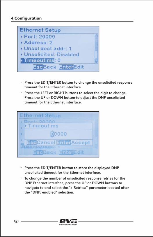
• Press the EDIT/ENTER button to change the unsolicited response timeout for the Ethernet interface.
• Press the LEFT or RIGHT buttons to select the digit to change. Press the UP or DOWN button to adjust the DNP unsolicited timeout for the Ethernet interface.
• Press the EDIT/ENTER button to store the displayed DNP unsolicited timeout for the Ethernet interface.
• To change the number of unsolicited response retries for the DNP Ethernet interface, press the UP or DOWN buttons to navigate to and select the “> Retries:” parameter located after the “DNP: enabled” selection.

51AT SERIES BATTERY CHARGER
4 Confi guration
• Press the EDIT/ENTER button to change the number of unsolicited response retries for the DNP Ethernet interface.
• Press the LEFT or RIGHT buttons to select the digit to change. Press the UP or DOWN button to adjust the number of unsolicited response retries for the DNP Ethernet interface.
• Press the EDIT/ENTER button to store the displayed number of unsolicited response retries for the DNP Ethernet interface.


5. DNP3.0
AT SERIES BATTERY CHARGER

54AT SERIES BATTERY CHARGER
5 DNP3.0
5.1 Introduction This manual section describes the specifi c implementation of the DNP3 Level 2 protocol via the EVO communications adapters. This section, in conjunction with the DNP3 Basic 4 Document Set, and the DNP Subset Defi nitions Document, provides complete information on how to communicate to the charger via the DNP3 interface.
This implementation of DNP3 is fully compliant with DNP3 Subset Defi nition Level 2, contains many Subset Level 3 features, and contains some functionality even beyond Subset Level 3.
5.2 Introduction The following table provides a “Device Profi le Document” in the standard format defi ned in the DNP3 Subset Defi nitions Document. While it is referred to in the DNP3 Subset Defi nitions as a “Document,” it is only a component of a total interoperability guide. This table, in combination with the following should provide a complete interoperability/confi guration guide for the DNP3 interface on the EVO Serial Communications Adapter:
• The Implementation Table provided in Section 5.3
• The Point List Tables in beginning in Section 5.4
DNP3 DEVICE PROFILE DOCUMENTVendor Name: HindlePower, Inc. - 1075 Saint John Street - Easton, PA 18042
Device Name: ATevo Communications Modules
Highest DNP Level Supported Device Function
For Request Level 2 - Master
For Responses Level 2 Slave
Notable objects, functions, and/or qualifi ers supported in addition to the Highest DNP Levels Support-ed (the complete list is described in the attached table):
Maximum Data Link Frame Size (octets) Maximum Application Fragment Size (octets)
Transmitted 292 Transmitted 2048
Received 292 Received 2048

55AT SERIES BATTERY CHARGER
5 DNP3.0
DNP3 DEVICE PROFILE DOCUMENT (CONT.)Maximum Data Link Re-tries Maximum Application Layer Re-tries
None None
- Fixed at 3 - Confi gurable
- Confi gurable range 0 - 255
Requires Data Link Confi rmation...
Never
- Always
- Sometimes
- Confi gurable
Requires Application Layer Confi rmation...
- Never
- Always
When reporting event data
- When sending multi-fragment responses
- Sometimes
- Confi gurable
Timeouts While Waiting For...
Data Link Confi rm - None Fixed @ 2000 - Variable - Confi gurable
Complete Appl. Fragment None - Fixed @ ____ - Variable - Confi gurable
Application Confi rm - None Fixed @ 2000 - Variable - Confi gurable
Complete Appl. Repsone None - Fixed @ ____ - Variable - Confi gurable
Others
Inter-character Timeout Fixed @ 50ms
Select/Operate Arm Timeout Fixed @ 5000ms
Binary Input Change Scanning Period Fixed @ 5000ms
Analog Input Change Scanning Period Fixed @ 5000ms
Unsolicited Offl ine Interval
Fixed @ 30000 ms if unsolicited messages is off.Confi gurable if unsolicited messages is on. See setup.
Unsolicted Response Notifi cation Delay Fixed @ 15000ms
Delay Measurement 100ms
Synchronization 1000ms

56AT SERIES BATTERY CHARGER
5 DNP3.0
DNP3 DEVICE PROFILE DOCUMENT (CONT.)Sends/Executes Control Operations
WRITE Binary Outputs Never Always Sometimes Confi gurable
SELECT/OPERATE Never Always Sometimes Confi gurable
DIRECT OPERATE Never Always Sometimes Confi gurable
DIRECT OPERATE - NO ACK Never Always Sometimes Confi gurable
Count >1 Never Always Sometimes Confi gurable
Pulse On Never Always Sometimes Confi gurable
Pluse Off Never Always Sometimes Confi gurable
Latch On Never Always Sometimes Confi gurable
Latch Off Never Always Sometimes Confi gurable
Queue Never Always Sometimes Confi gurable
Clear Queue Never Always Sometimes Confi gurable
Explanation of Sometimes: See the Binary Outputs point list in Section 5.4.2
Reports Binary Input Change Events when no specifi c variation requested
Reports time-tagged Binary Input Change Events when no specifi c variation requested
Never Never
Only time-tagged Binary Input Change With Time
Only non-time-tagged Binary Input Change With Relative Time
Confi gurable Confi gurable (attach explanation)
Sends Unsolicited Responses Sends Static Data in Unsolicited Responses:
Never Never
Confi gurable, See DNP confi guration section
When Device Restarts
Only certain objects When Status Flags Change
Sometimes (attach explanation)No other options are permitted.
ENABLE/DISABLE UNSOLICITED Function codes supported
Default Counter Object/Variation Counters Roll Over at:
No Counters Reported No Counters Reported
Confi gurable Confi gurable (attach explanation)
Default Object: 20 and 21 16 Bits
Default Variation 32 Bits
Point-by-point list attached Other Value:____________
Point-by-point list attached
Sends Multi-Fragment Responses
Yes
No

57AT SERIES BATTERY CHARGER
5 DNP3.0
DNP3 DEVICE PROFILE DOCUMENT (CONT.)Sequential File Transfer Support
Append File Mode Yes No
Custom Status Code Strings Yes No
Permission Field Yes No
File Events Assigned to Class Yes No
File Events Poll Specifi cally Yes No
File Events Send Immediately Yes No
Multiple Blocks in a Fragment Yes No
Max Number of Files Open 0

58AT SERIES BATTERY CHARGER
5 DNP3.0
5.3 Implementation Table The following table identifi es the variations, function codes, and qualifi ers supported by the EVO Communications Adapter in both request messages and in response messages.
For static (non-change-event) objects, requests sent with qualifi ers 00, 01, 06, 07, or 08, will be responded with qualifi ers 00 or 01. Static object requests sent with qualifi ers 17 or 28 will be responded with qualifi ers 17 or 28. For change-event objects, qualifi ers 17 or 28 are always responded except in the case of object 70 change events which respond with qualifi er 1B or 5B.
Indicates Subset Level 3 functionality (beyond Subset Level 2)
Indicates Functionality beyond Subset Level 3
OBJECTREQUEST
(LIBRARY PARSE)
RESPONSE(LIBRARY WILL RE-
SPOND WITH)
Object Number
Variation Number
DescriptionFunction Codes (dec)
Qualifi er Codes (hex)
Function Codes (dec)
Qualifi eir Codes (hex)
1 0
Binary Input (Variation 0 is used to re-quest default
variation)
1 (read)
00,01 (start-stop)
129 (re-sponse)
00,01 (start-stop)
06 (no range, or all)
17,28 (index - see note 2)22 (assign
class)
07,08 (limited qty)
17,28 (index)
1
1 (default see note
1)
BinaryInput
1 (read)
00,01 (start-stop)
129 (response
00,01 (start-stop)
06 (no range, or all)
17,28 (index - see note 2)22 (assign
class)
07,08 (limited qty)
17,28 (index)

59AT SERIES BATTERY CHARGER
5 DNP3.0
1 2Binary Input with Status
1 (read)00,01 (start-
stop)
129 (response
00,01 (start-stop)
06 (no range, or all)
22 (assign class) 17,28 (index -
see note 2)07,08 (limited
qty)
17,28 (index)
2 0
Binary Input Change (Variation 0 is used to re-quest default
variation)
1 (read)
06 (no range, or all)
129 (re-sponse)
17, 28 (index)
07, 08 (limited qty)
130 (unsol. resp)
2 1Binary Input
Changed without Time
1 (read)
06 (no range, or all)
129 (re-sponse)
17, 28 (index)
07, 08 (limited qty)
130 (unsol. resp)
22 (default - see note
1)
Binary Input Change with
Time1 (read)
06 (no range, or all)
129 (re-sponse)
17, 28 (index)07, 08 (limited
qty)130 (unsol.
resp)
10 0
Binary Output Status (Varia-tion 0 is used
to request default
variation)
1 (read)
00,01 (start-stop)
129 (response)
00,01 (start-stop)06 (no range,
or all)
07,08 (limited qty) 17,28 (index -
see note 2)17,28 (index)
102 (default see note
1)
Binary Output Status
1 (read)
00,01 (start-stop)
129 (response)
00,01 (start-stop)
06 (no range, or all)
17,28 (index - see note 2)
07,08 (limited qty)
17,28 (index)

60AT SERIES BATTERY CHARGER
5 DNP3.0
12 1Control Relay Output Block
3 (select) 00,01 (start-stop)
129 (response)
echo of request
4 (operate) 07,08 (limited qty)
5 (direct op)
17,28 (index)6 (dir. op,
noack)
30 0
Analog Input (variation 0
is used to re-quest default
variation)
1 (read)
00,01 (start-stop)
129 (response)
00,01 (start-Stop)06 (no range,
or all)
22 (assign class)
07,08 (limited qty) 17,28 (index -
see note 2)17,28 (index)
30 132-Bit Analog
Input
1 (read)
00,01 (start-stop)
129 (response)
00,01 (start-Stop)
06 (no range, or all)
17,28 (index - see note 2)22 (assign
class)
07,08 (limited qty)
17,28 (index)
30
2default - see note
1)
16-Bit Analog Input
1 (read)
00,01 (start-stop)
129 (response)
00,01 (start-Stop)
06 (no range, or all)
17,28 (index - see note 2)22 (assign
class)
07,08 (limited qty)
17,28 (index)
30 332-Bit Analog Input without
Flag
1 (read)
00,01 (start-stop)
129 (response)
00,01 (start-Stop)
06 (no range, or all)
17,28 (index - see note 2)22 (assign
class)
07,08 (limited qty)
17,28 (index)
30 416-Bit Analog Input without
Flag
1 (read)
00,01 (start-stop)
129 (response)
00,01 (start-Stop)
06 (no range, or all)
17,28 (index - see note 2)22 (assign
class)
07,08 (limited qty)
17,28 (index)

61AT SERIES BATTERY CHARGER
5 DNP3.0
32 0
Analog Change Event (variation 0 is
used to request default
variation)
1 (read)
06 (no range or call)
129 (response)
17,28 (index)
07,08 (limited qty)
130 (unsol. resp)
32 132-bit Analog Change Event without Time
1 (read)
06 (no range or call)
129 (response)
17,28 (index)130
(unsol. resp)07,08 (limited
qty)
322 (default - see note
1)
16-bit Analog Change Event without Time
1 (read)
06 (no range or call)
129 (response
17,28 (index)130 (unsol. resp)
07,08 (limited qty)
32 332-bit Analog Change Event
with Time1 (read)
06 (no range or call)
129 (response)
17,28 (index)130
(unsol. resp)07,08 (limited
qty)
32 416-bit Analog Change Event
with Time1 (read)
06 (no range or call)
129 (response)
17,28 (index)130
(unsol. resp)07,08 (limited
qty)
34 0
Analog Input Reporting Deadband (variation 0
is used to re-quest default
variation)
1 (read)
00,01 (start-stop)
129 (response)
00,01 (start-stop)06 (no range,
or all)
07,08 (limited qty) 17,28 (index -
see note 2)17,28 (index)
341 (default see note
1)
16 bit Analog Input Report-ing Deadband
1 (read)
00,01 (start-stop)
129 (response)
00,01 (start-stop)06 (no range,
or all)
07,08 (limited qty) 17,28 (index -
see note 2)17,28 (index)
2 (write)
00,01 (start-stop)
07,08 (limited qty)
17,28 (index)

62AT SERIES BATTERY CHARGER
5 DNP3.0
34 216 bit Analog Input Report-ing Deadband
1 (read)
00,01 (start-stop)
129 (response)
00,01 (start-stop)06 (no range,
or all)
07,08 (limited qty) 17,28 (index -
see note 2)17,28 (index)
2 (write)
00,01 (start-stop)
07,08 (limited qty)
17,28 (index)
40 0
Analog Output Status
(variation 0 is used to re-quest default
variation)
1 (read)
00,01 (start-stop)
129 (response)
00,01 (start-stop)06 (no range,
or all)
07,08 (limited qty) 17,28 (index -
see note 2)17,28 (index)
40 132-Bit Analog Output Status
1 (read)
00,01 (start-stop)
129 (response)
00,01 (start-stop)06 (no range,
or all)
07,08 (limited qty) 17,28 (index -
see note 2)17,28 (index)
40
2(default - see note
1)
16-Bit Analog Output Status
1 (read)
00,01 (start-stop)
129 (response)
00,01 (start-stop)06 (no range,
or all)
07,08 (limited qty) 17,28 (index -
see note 2)17,28 (index)
41 132-Bit Output
Block
3 (select) 00,01 (start-stop)
129 (response)
echo of request
4 (operate)07,08 (limited
qty)5 (direct op)
17,28 (index)6 (dir. op, noack)
41 216-Bit Output
Block
3 (select) 00,01 (start-stop)
129 (response)
echo of request
4 (operate)07,08 (limited
qty)5 (direct op)
17,28 (index)6 (dir. op, noack)

63AT SERIES BATTERY CHARGER
5 DNP3.0
50 0Time and
Date1 (read)
00,01 (start-stop)
129 (response)
00,01 (start-stop)06 (no range,
or all)
07,08 (limited qty) 17,28 (index -
see note 2)17,28 (index)
501 (default - see note
1)
Time and Date
1 (read)
00,01 (start-stop)
129 (response)
00,01 (start-stop)06 (no range,
or all)
07,08 (limited qty) 17,28 (index -
see note 2)17,28 (index)
2 (write)
00,01 (start-stop)
129 (response)
06 (no range, or all)
07 (limited qty=1)
08 (limited qty)
17,28 (index)
60 1Classs 0,
Data
1 (read)06 (no range,
or all)129
(response)00,01 (start-
stop)22 (assign class)
60 2 Class 1 Data
1 (read)
06 (no range, or all)
129 (response)
17,28 (index - see note 2)
07,08 (limited qty)
20 (enbl. unsol.)
06 (no range, or all)
21 (dsbl. unsol.)
22 (assign class)
60 3 Class 2 Data
1 (read)
06 (no range, or all)
129 (response)
17,28 (index - see note 2)
07,08 (limited qty)
20 (enbl. unsol.)
06 (no range, or all)
21 (dsbl. unsol.)
22 (assign class)

64AT SERIES BATTERY CHARGER
5 DNP3.0
60 4 Class 3 Data
1 (read)
06 (no range, or all)
129 (response)
17,28 (index - see note 2)
07,08 (limited qty)
20 (enbl. unsol.)
06 (no range, or all)
21 (dsbl. unsol.)
22 (assign class)
No Object (function code only) - See Note 313 (Cold Restart)
No Object (function code only)14 (Warm Restart)
No Object (function code only)23 (Delay
Meas.)
Note 1: A Default variation refers to the variation responded when variation 0 is requested and/or in class 0, 1, 2, or 3 scans.
Note 2:For static (non-change-event) objects, qualifi ers 17 or 28 are only responded when a request is sent with qualifi ers 17 or 28, respectively. Otherwise, static object requests sent with qualifi ers 00, 01, 06, 07, or 08, will be responded with qualifi ers 00 or 01. (For change event objects, qualifi ers 17 or 28 are always responded except for object 70, which responds with qualifi er 1B or 5B.)
Note 3:For the EVO Communications Modules, a cold restart is implemented as a warm restart. The ex-ecutable is not restarted, but the DNP process is restarted.
Note 4: Writes of Internal Indications are only supported for index 7 (Restart IIN1-7), and indices 16 and beyond (user-defi ned indications).

65AT SERIES BATTERY CHARGER
5 DNP3.0
5.4 DNP Points Lists The tables in the following sections identify all the individual data points provided by this implementation of DNP3.
5.4.1 Binary Input Points The following table lists Binary Inputs (Object 1).

66AT SERIES BATTERY CHARGER
5 DNP3.0
Binary Input Points
Static (Steady-State) Object Number 1
Change Event Object Number 2
Request Function Codes supported:1 (read)
22 (assign class)
Static Variation reported when variation 0 requested: 1 (Binary Input without status)
Change Event Variation reported when variation 0 requested: 2 (Binary Input Change with Time)
Change Event Scan Rate: 5 seconds
Point Index Name/Description If Point Status is
Logic ‘1’
Initial Event Class
0 High Voltage DC (HVDC) Alarm active 1
1 Low Voltage DC (LVDC) Alarm active 1
2 DC Output Failure Alarm active 1
3 AC input Failure Alarm active 1
4 Positive Ground Fault Alarm active 1
5 Negative Ground Fault Alarm active 1
6 Common Alarm Relay (CAR) Alarm active 1
7 High Voltage DC (HVDC) Shutdown active 1
8 Low Voltage AC (LVAC) Shutdown active 1
9 Forced Load Sharing Enabled enabled 1
10 Temperature Probe Enabled enabled 1
11 Defective Temperature Probe defective 1
12 Equalize Mode (0 = fl oat) equalize 1
13 (Not Used) - 1
14 (Not Used) - 1
15 Auto-Equalize Timer enabled 1
16 HVDC Shutdown Enabled enabled 1
17 (Not Used) - 1
18 High Ripple Alarm active 1
19 End of Discharge Alarm active 1
20 Rectifi er Over Temperature Alarm active 1
21 DC Breaker Status open 1
22 External Voltage Sense Fail Alarm active 1
23 Internal Voltage Sense Fail Alarm active 1
24 DC Power Supply Alarm active 1
25 Open DC Output Alarm active 1
26 High Level Detect Alarm active 1
27 Low Level Detect Alarm active 1
28 Low AC Shutdown Alarm active 1
29 Current Limit Status active 1
30 High Level Detect Shutdown Status active 1
31 Alarm Relay Failure active 1
32 Rectifi er Temperature Sense Failure active 1
33 Display Processor Failure active 1

67AT SERIES BATTERY CHARGER
5 DNP3.0
5.4.2 Binary Output Points The following table lists Binary Outputs (Object 10).
Binary Output Status Points
Object Number Status 10
Binary Output Status Points 1 (read)
Default Variation reported when variation 0 requested 2 (Binary Output Status)
Control Relay Output Blocks
Object Number 12
Request Function Codes supported3 (select), 4 (operate)5 (direct operate), 6 (direct oper-ate, noack)
Point Index Name/Description Latch ‘OFF’ Latch ‘ON’
0 Float / Equalize Mode fl oat equalize
1 (Not Used) - -
2 (Not Used) - -
3 Manual Timer / Auto Equalize Timer manual auto
4 HVDC Shutdown disable enable
5 (Not Used) - -
6 Battery Temperature Compensation disable enable
5.4.3 Analog Input Status Points The following table lists Analog Inputs (Object 30).
It is important to note that 16 bit and 32 bit variations of Analog Inputs, Analog Output Control Blocks, and Analog Output Statuses are transmitted through DNP as signed numbers. Even for analog input points that are not valid as negative values, the maximum positive representation is 32767.
For each point, the “Multiplier” column indicates the value the point data is multiplied by. Since all data is sent in integer format, fl oating point numbers are multiplied by a constant (1, 10, or 100) to maintain the decimal information. For example, points with two decimal places are multiplied by 100 (5.67 is sent as 567), points with one decimal point of resolution are multiplied by 10 (8.2 is sent as 82). To convert the point data to the correct value, simply divide the point by the value listed in the ‘Multiplier’ column.
68AT SERIES BATTERY CHARGER
5 DNP3.0
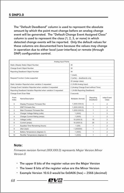
The “Default Deadband” column is used to represent the absolute amount by which the point must change before an analog change event will be generated. The “Default Change Event Assigned Class” column is used to represent the class (1, 2, 3, or none) in which detected change events will be reported. Only the default values for these columns are documented here because the values may change in operation due to either local (user-interface) or remote (through DNP) confi guration control.
Analog Input Points
Static (Steady State) Object Number 30
Change Event Object Number 32
Reporting Deadband Object Number 34
Request Function Codes supported
1 (read),
2 (write) – deadbands only
22 (assign class)
Static Variation Reported when variation 0 requested 2 (16-Bit Analog Input)
Change Event Variation Reported when variation 0 requested 2 (Analog Change Event without Time)
Reporting Deadband Variation Reported when variation 0 requested 1 (16-Bit Reporting Deadband)
Change Event Scan Rate 5 seconds
Point Index Name/Description Multiplier (format) Reporting
DeadbandInitial Event
Class
0 Display Processor Firmware Rev 1 (XXX.XXX.0) 1 2
1 DNP Firmware Rev 1 (XXX.XXX.0) 1 2
2 Main Processor Firmware Rev 1 (XXX.XXX.0) 1 2
3 Charger Voltage Rating (volts) 1 (XXX) 1 2
4 Charger Current Rating (amps) 1 (XXX) 1 2
5 Voltage (volts) 10 (XXX.X) 10 2
6 Current (amps) 10 (XXX.X) 20 2
7 Equalize Time Remaining (hours) 1 (XX) 1 2
8 (Not Used) 1 (XXXXX) 1 2
9 Battery Temperature (degrees C) 1 (XXX) 1 2
10 Rectifi er Temperature (degrees C) 1 (XXX) 1 2
Note: Firmware revision format (XXX.XXX.0) represents Major Version.Minor Version.0
• The upper 8 bits of the register value are the Major Version
• The lower 8 bits of the register value are the Minor Version
• Example Version 10.6.0 would be 0x0A06 (hex) = 2566 (decimal)

69AT SERIES BATTERY CHARGER
5 DNP3.0
5.4.4 Analog Output Status Points The following table lists Analog Outputs (Object 40). The valid range for many of these points depends on the EVO model type (voltage and current rating). Refer to the EVO Operations and Service Manual to determine the valid ranges for these set points. It is important to note that 16 bit and 32 bit variations of Analog Inputs, Analog Output Control Blocks, and Analog Output Statuses are transmitted through DNP as signed numbers. Even for analog input points that are not valid as negative values, the maximum positive representation is 32767.
For each point, the “Multiplier” column indicates the value the point data is multiplied by. Since all data is sent in integer format, fl oating point numbers are multiplied by a constant (1, 10, or 100) to maintain the decimal information. For example, points with two decimal places are multiplied by 100 (5.67 is sent as 567), points with one decimal point of resolution are multiplied by 10 (8.2 is sent as 82). To convert the point data read to the correct value, simply divide the point by the value listed in the ‘Multiplier’ column.
When writing a value to the Analog Output, you must multiply the desired value by the constant in the ‘Multiplier’. For example, if you want to change the ‘Float Voltage Set Point’ to 132 volts, you would need to write 1320 to Analog Output ‘0’ (132 X 10 = 1320). The ‘10’ is the multiplier constant listed in ‘Multiplier’ column for Analog Output Point ‘0’.
The ‘Valid Range’ column lists the possible values that can be successfully written to the associated Analog Output point. This is the true value and does not include the multiplier correction. Attempting to write values outside of this range will result in a DNP3 error response.

70AT SERIES BATTERY CHARGER
5 DNP3.0
Analog Output Status Points
Object Number 40
Request Function Codes Supported 1 (read)
Default variation reported when variation 0 requested 2 (16-Bit Analog Input)
Analog Output Blocks
Object Number 41
Request Function Codes supported3 (select), 4 (operate)5 (direct operate), 6 (direct oper-ate, noack)
Point Index Name/Description Multiplier
(format) Valid Range
0 Float Voltage Set Point (volts)10 XXX.X) See Operation
& Service Manual
1 Equalize Voltage Set Point (volts) 10 (XXX.X) See Operation
& Service Manual
2 Equalize Timer Set Point (hours) 1 (XX) 1 <= XX <= 99
3 Current Limit Set Point (amps)10 (XXX.X) See Operation
& Service Manual
4 High Voltage DC Alarm Set Point (volts)10 (XXX.X) See Operation
& Service Manual
5 Low Voltage DC Alarm Set Point (volts)10 (XXX.X) See Operation
& Service Manual
6 High Level Detect Set Point (volts)10 (XXX.X) See Operation
& Service Manual
7 Low Level Detect Set Point (volts)10 (XXX.X) See Operation
& Service Manual
8 End of Discharge Set Point (volts)10 (XXX.X) See Operation
& Service Manual
9 AC Ripple Alarm Set Point (m-volts)1 (XXX) 50 < XXX <
250 (in 5mV steps)
10 Positive Ground Fault Set Point (k-ohms)1 (XX) 10K <= XX
<= 40K (in 1 K-ohm steps)
11 Negative Ground Fault Set Point (k-ohms)1 (XX) 10K <= XX
<= 40K (in 1 K-ohm steps)
12 Battery Type (chemistry) 1 (X) 0 – lead acid 1 - NiCAD

71AT SERIES BATTERY CHARGER
5 DNP3.0
5.4.5 Internal Indication (IIN) The following Internal Indication bits are defi ned by the DNP3 protocol.
Internal Indications
Object Number 80
Request Function Codes Supported 1 (read), 2 (write)
Default Variation reported when variation 0 requested
Point Index Descriptions and Conditions Writable?
0IIN1-0 All Stations – set after a broadcast message (any me sage using a destination address of 0xff f0 or above) has been received. Does not indicate an error condition.
No
1 IIN1-1 Class 1 event data available. Can be set at any time and does not indicate an error condition.
No
2 IIN1-2 Class 2 event data available. Can be set at any time and does not indicate an error condition.
No
3 IIN1-3 Class 3 event data available. Can be set at any time and does not indicate an error condition.
No
4 IIN1-4 Time synchronization required. Can be set at any time and does not indicate an error condition.
No
5 IIN1-5 Local mode. Set if some points are uncontrollable via DNP.
No
6 IIN1-6 Device Trouble. No
7 IIN1-7 Device restart. Set only under specifi c conditions. Does not indicate an error condition.
Yes
8 IIN2-0 Function Unknown. Generally means that the function code (octet 2 of the request header) cannot be processed.
No
9IIN2-1 Object Unknown. Generally means that the function code could be processed but the object group / variation could not be processed.
No
10IIN2-2 Parameter Error. Generally indicates that both the function code and object group / variation could be processed but that the qualifi er / range fi eld is in error.
No
11IIN2-3 Buff er Overfl ow. Indicates that an event buff er has overfl owed, and that change events, of at least one type, have been lost.
No
12 IIN2-4 Already Executing No
13 IIN2-5 Bad confi guration. No
14 IIN2-6 Reserved. Always 0. No
15 IIN2-7 Reserved. Always 0. No

6. MODBUS
AT SERIES BATTERY CHARGER

73AT SERIES BATTERY CHARGER
6 MODBUS
6.1 Introduction This manual section describes the specifi c implementation of the Modbus protocol via the EVO Communications Adapters. The Modbus protocol was implemented using the Modicon Modbus Protocol Reference Guide PI-MBUS-300 Rev. J.
6.2 Supported Function Codes The following standard Modbus function codes are supported:
• 01 – Read Coil Status
• 02 – Read Input Status
• 03 – Read Holding Registers
• 04 – Read Input Registers
• 05 – Read Single Coil
• 06 – Preset Single Register
• 15 – Force Multiple Coils
• 16 – Preset Multiple Registers
6.3 Modbus Binary Outputs (Coils) The following table lists the Binary Output registers.:
Address Name/Description Status ‘OFF’ (Logic ‘0’) Status ‘ON’ (Logic ‘1’)
00001 Float / Equalize Mode fl oat equalize
00002 (Not Used) - -
00003 (Not Used) - -
00004 Manual Timer / Auto Equalize Timer manual auto
00005 HVDC Shutdown disable enable
00006 (Not Used) - -
00007 Battery Temperature Compensation disable enable

74AT SERIES BATTERY CHARGER
6 MODBUS
6.4 Binary Inputs The following table lists Binary Input Status registers.
Address Name/Description If Status is ‘ON’ (Logic ‘1’)
10001 High Voltage DC (HVDC) Alarm active
10002 Low Voltage DC (LVDC) Alarm active
10003 DC Output Failure Alarm active
10004 AC input Failure Alarm active
10005 Positive Ground Fault Alarm active
10006 Negative Ground Fault Alarm active
10007 Common Alarm Relay (CAR) Alarm active
10008 High Voltage DC (HVDC) Shutdown Active active
10009 Low Voltage AC (LVAC) Shutdown active
10010 Forced Load Sharing Enabled enabled
10011 Temperate Probe Enabled enabled
10012 Defective Temperate Probe defective
10013 Equalize Mode (0 = fl oat) equalize
10014 (Not Used) -
10015 (Not Used) -
10016 Auto-Equalize Timer enabled
10017 HVDC Shutdown Enabled enabled
10018 (Not Used) -
10019 High Ripple Alarm active
10020 End of Discharge Alarm active
10021 Rectifi er Over Temperature Alarm active
10022 DC Breaker Status open
10023 External Voltage Sense Fail Alarm active
10024 Internal Voltage Sense Fail Alarm active
10025 DC Power Supply Alarm active
10026 Open DC Output Alarm active
10027 High Level Detect Alarm active
10028 Low Level Detect Alarm active
10029 Low AC Shutdown Alarm active
10030 Current Limit Status active
10031 High Level Detect Shutdown Status active
10032 Alarm Relay Failure active
10033 Rectifi er Temperature Sense Failure active
10034 Display Processor Failure active

75AT SERIES BATTERY CHARGER
6 MODBUS
6.5 Modbus Input Registers The following table lists the Modbus Input Registers.
For each point, the “Multiplier” column indicates the value the register data is multiplied by. Since all data is sent in integer format, fl oating point numbers are multiplied by a constant (1, 10, or 100) to maintain the decimal information. For example, registers with two decimal places are multiplied by 100 (5.67 is sent as 567), resisters with one decimal point of resolution are multiplied by 10 (8.2 is sent as 82). To convert the register data to the correct value, simply divide the register value by the value listed in the ‘Multiplier’ column.
Address Name/Description Multiplier (format)
30001 Display Processor Firmware Rev 1 (XXX.XXX.0)
30002 Modbus Firmware Rev 1 (XXX.XXX.0)
30003 Main Processor Firmware Rev 1 (XXX.XXX.0)
30004 Charger Voltage Rating (volts) 1 (XXX)
30005 Charger Current Rating (amps) 1 (XXX)
30006 Voltage (volts) 10 (XXX.X)
30007 Current (amps) 10 (XXX.X)
30008 Equalize Time Remaining (hours) 1 (XX)
30009 (Not Used) 1 (XXXXX)
30010 Battery Temperature (degrees C) 1 (XXX)
30011 Rectifi er Temperature (degrees C) 1 (XXX)
Note: Firmware revision format (XXX.XXX.0) represents Major Version.Minor Version.0
• The upper 8 bits of the register value are the Major Version
• The lower 8 bits of the register value are the Minor Version
• Example Version 10.6.0 would be 0x0A06 (hex) = 2566 (decimal)

76AT SERIES BATTERY CHARGER
6 MODBUS
6.6 Modbus Holdings Registers The following table lists the Modbus Holding Registers.
For each point, the “Multiplier” column indicates the value the register data is multiplied by. Since all data is sent in integer format, fl oating point numbers are multiplied by a constant (1, 10, or 100) to maintain the decimal information. For example, registers with two decimal places are multiplied by 100 (5.67 is sent as 567), resisters with one decimal point of resolution are multiplied by 10 (8.2 is sent as 82). To convert the register data to the correct value, simply divide the register value by the value listed in the ‘Multiplier’ column.
When writing a value to a Holding Register, you must multiply the desired value by the constant in the ‘Multiplier’. For example, if you want to change the ‘Float Voltage Set Point’ to 132 volts, you would need to write 1320 to Holding Register ‘40001’ (132 X 10 = 1320). The ‘10’ is the multiplier constant listed in ‘Multiplier’ column for Holding Register ‘40001’.
The ‘Valid Range’ column lists the possible values that can be successfully written to the associated Holding Register. This is the true value and does not include the multiplier correction. Attempting to write values outside of this range will result in a Modbus error returned as an Exception Response.

77AT SERIES BATTERY CHARGER
6 MODBUS
Address Name/Description Multiplier (format) Valid Range
40001 Float Voltage Set Point (volts) 10 (XXX.X) See Operation & Service Manual
40002 Equalize Voltage Set Point (volts) 10 (XXX.X) See Operation & Service Manual
40003 Equalize Timer Set Point (hours) 1 (XX) 1 <= XX <= 99
40004 Current Limit Set Point (amps) 10 (XXX.X) See Operation & Service Manual
40005 High Voltage DC Alarm Set Point (volts) 10 (XXX.X) See Operation & Service Manual
40006 Low Voltage DC Alarm Set Point (volts) 10 (XXX.X) See Operation & Service Manual
40007 High Level Detect Set Point (volts) 10 (XXX.X) See Operation & Service Manual
40008 Low Level Detect Set Point (volts) 10 (XXX.X) See Operation & Service Manual
40009 End of Discharge Set Point (volts) 10 (XXX.X) See Operation & Service Manual
40010 AC Ripple Alarm Set Point (m-volts) 1 (XXX) 50 < XXX < 250 (in 5mV steps)
40011 Positive Ground Fault Set Point (k-ohms) 1 (XX) 10K <= XX <= 40K (in 1 K-ohm steps)
40012 Negative Ground Fault Set Point (k-ohms) 1 (XX) 10K <= XX <= 40K (in 1 K-ohm steps)
40013 Battery Type (chemistry) 1 (X) 0 – lead acid 1 - NiCAD