Embed Size (px)
Citation preview
BR137 C&I Building Systems • December 2016 1
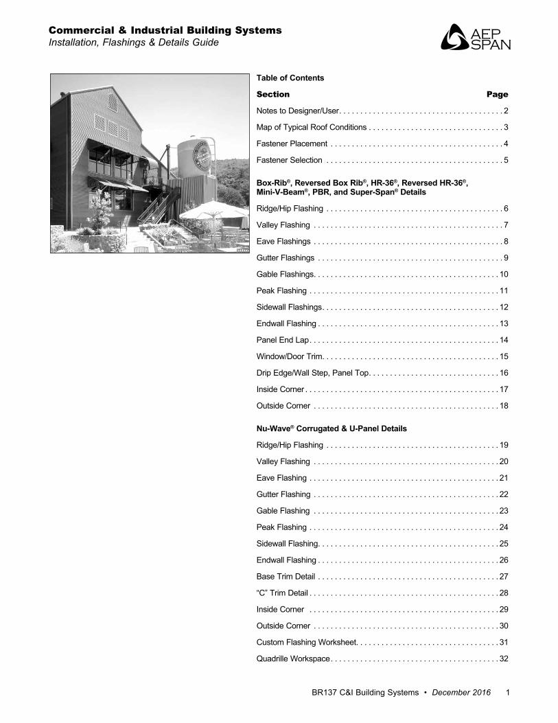
Table of Contents
Section Page
Notes to Designer/User . . . . . . . . . . . . . . . . . . . . . . . . . . . . . . . . . . . . . . . 2
Map of Typical Roof Conditions . . . . . . . . . . . . . . . . . . . . . . . . . . . . . . . . 3
Fastener Placement . . . . . . . . . . . . . . . . . . . . . . . . . . . . . . . . . . . . . . . . . 4
Fastener Selection . . . . . . . . . . . . . . . . . . . . . . . . . . . . . . . . . . . . . . . . . . 5
Box-Rib®, Reversed Box Rib®, HR-36®, Reversed HR-36®,Mini-V-Beam®, PBR, and Super-Span® Details
Ridge/Hip Flashing . . . . . . . . . . . . . . . . . . . . . . . . . . . . . . . . . . . . . . . . . . 6
Valley Flashing . . . . . . . . . . . . . . . . . . . . . . . . . . . . . . . . . . . . . . . . . . . . . 7
Eave Flashings . . . . . . . . . . . . . . . . . . . . . . . . . . . . . . . . . . . . . . . . . . . . . 8
Gutter Flashings . . . . . . . . . . . . . . . . . . . . . . . . . . . . . . . . . . . . . . . . . . . . 9
Gable Flashings . . . . . . . . . . . . . . . . . . . . . . . . . . . . . . . . . . . . . . . . . . . . 10
Peak Flashing . . . . . . . . . . . . . . . . . . . . . . . . . . . . . . . . . . . . . . . . . . . . . 11
Sidewall Flashings . . . . . . . . . . . . . . . . . . . . . . . . . . . . . . . . . . . . . . . . . . 12
Endwall Flashing . . . . . . . . . . . . . . . . . . . . . . . . . . . . . . . . . . . . . . . . . . . 13
Panel End Lap . . . . . . . . . . . . . . . . . . . . . . . . . . . . . . . . . . . . . . . . . . . . . 14
Window/Door Trim . . . . . . . . . . . . . . . . . . . . . . . . . . . . . . . . . . . . . . . . . . 15
Drip Edge/Wall Step, Panel Top . . . . . . . . . . . . . . . . . . . . . . . . . . . . . . . 16
Inside Corner . . . . . . . . . . . . . . . . . . . . . . . . . . . . . . . . . . . . . . . . . . . . . . 17
Outside Corner . . . . . . . . . . . . . . . . . . . . . . . . . . . . . . . . . . . . . . . . . . . . 18
Nu-Wave® Corrugated & U-Panel Details
Ridge/Hip Flashing . . . . . . . . . . . . . . . . . . . . . . . . . . . . . . . . . . . . . . . . . 19
Valley Flashing . . . . . . . . . . . . . . . . . . . . . . . . . . . . . . . . . . . . . . . . . . . . 20
Eave Flashing . . . . . . . . . . . . . . . . . . . . . . . . . . . . . . . . . . . . . . . . . . . . . 21
Gutter Flashing . . . . . . . . . . . . . . . . . . . . . . . . . . . . . . . . . . . . . . . . . . . . 22
Gable Flashing . . . . . . . . . . . . . . . . . . . . . . . . . . . . . . . . . . . . . . . . . . . . 23
Peak Flashing . . . . . . . . . . . . . . . . . . . . . . . . . . . . . . . . . . . . . . . . . . . . . 24
Sidewall Flashing . . . . . . . . . . . . . . . . . . . . . . . . . . . . . . . . . . . . . . . . . . . 25
Endwall Flashing . . . . . . . . . . . . . . . . . . . . . . . . . . . . . . . . . . . . . . . . . . . 26
Base Trim Detail . . . . . . . . . . . . . . . . . . . . . . . . . . . . . . . . . . . . . . . . . . . 27
“C” Trim Detail . . . . . . . . . . . . . . . . . . . . . . . . . . . . . . . . . . . . . . . . . . . . . 28
Inside Corner . . . . . . . . . . . . . . . . . . . . . . . . . . . . . . . . . . . . . . . . . . . . . 29
Outside Corner . . . . . . . . . . . . . . . . . . . . . . . . . . . . . . . . . . . . . . . . . . . . 30
Custom Flashing Worksheet . . . . . . . . . . . . . . . . . . . . . . . . . . . . . . . . . . 31
Quadrille Workspace . . . . . . . . . . . . . . . . . . . . . . . . . . . . . . . . . . . . . . . . 32
Commercial & Industrial Building SystemsInstallation, Flashings & Details Guide
Commercial & Industrial Building SystemsInstallation, Flashings & Details Guide
2 www.aepspan.com
The details contained in this packet are intended to be a design aid and do not depict all situations. Modifications are the responsibility of the designer/user and should take into account climate conditions such as wind and snow, governing code requirements, and the actual usage and maintenance of the structure. Where possible, roof panel side laps and flashings should be lapped away from prevailing winds. Certain flashings should be supported if it is likely that a ladder will be used against them or if foot traffic is anticipated. Check with AEP Span any time you intend to specify a prefinished flashing in a gauge different than the panels. It is good practice to specify that all flashings be of the same material as the panels (gauge, color, finish) to ensure long-term durability. Field-painted flashings rarely equal the durability and color fastness of factory baked-on paint systems. Where possible, we have hemmed the edges of flashings to strengthen them and to minimize the exposure of cut edges.
Framing The details contained in this guide are shown with panels attached to spaced support members.
Slope requirements It is suggested that all panels in this booklet be used on slopes of 1:12 or greater, except Nu-Wave® Corrugated and U-Panel which have a 3:12 minimum slope requirement.
Condensation, Insulation & Ventilation It is the designer’s responsibility to determine the need and composition of condensation control materials including insulation and vapor retarders, as well as ventilation requirements. Metal roofing is susceptible to condensation and its control should be carefully considered.
Valleys Valley dimensions must be the proper width to account for slope, snow, ice, and rain conditions. If valleys are not kept free of debris, water can back up and intrusion may occur under the panels.
Snow Design If possible, valleys, gutters, roof elevation changes and penetrations should be minimized or eliminated in snow areas. Roof penetrations should be located as close to the ridge or peak of the roof as possible to minimize accumulations of ice and snow.
Curved Roofs Box Rib, HR-36®, Super-Span®, U-Panel, and Nu-Wave® Corrugated panels are suitable for installation over curved surfaces. Box Rib, HR-36, U-Panel and Super Span panels are factory crimp curved. Nu-Wave Corrugated panels are factory smooth curved. Mini-V-Beam and PBR panels are not currently available curved.
Oil-Canning Flat metal surfaces will display waviness commonly referred to as “oil-canning”. This is caused by steel mill tolerances, variations in the substrate and roofing underlayments. Oil canning is a characteristic, not a defect, of panels manufactured from light-gauge metal. Coils are factory “corrective-levelled” prior to rollforming to minimize oil canning. Oil canning is not a cause for panel rejection. Additional information is available upon request.
References The Sheet Metal and Air Conditioning Contractors’ National Association Inc. (SMACNA) manual is an excellent reference for sheet metal contractors. Its guidelines for underlayments, gutter and downspout size requirements, and expansion/contraction of metals and flashings joints should be followed.
Technical Assistance Call your AEP Span Sales or Technical Representative for additional information on any of these subjects.
Definitions
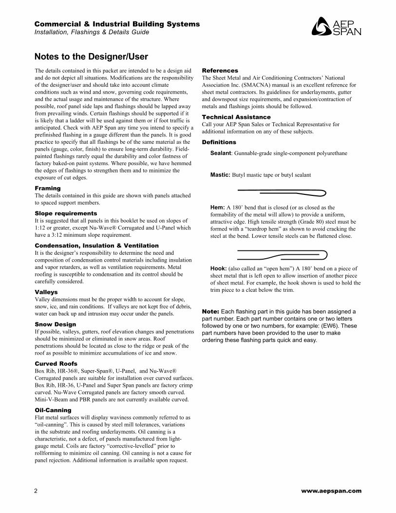
Sealant: Gunnable-grade single-component polyurethane
Mastic: Butyl mastic tape or butyl sealant
Hem: A 180˚ bend that is closed (or as closed as the formability of the metal will allow) to provide a uniform, attractive edge. High tensile strength (Grade 80) steel must be formed with a “teardrop hem” as shown to avoid cracking the steel at the bend. Lower tensile steels can be flattened close.
Hook: (also called an “open hem”) A 180˚ bend on a piece of sheet metal that is left open to allow insertion of another piece of sheet metal. For example, the hook shown is used to hold the trim piece to a cleat below the trim.
Note: Each flashing part in this guide has been assigned a part number . Each part number contains one or two letters followed by one or two numbers, for example: (EW6) . These part numbers have been provided to the user to make ordering these flashing parts quick and easy.
Notes to the Designer/User
BR137 C&I Building Systems • December 2016 3
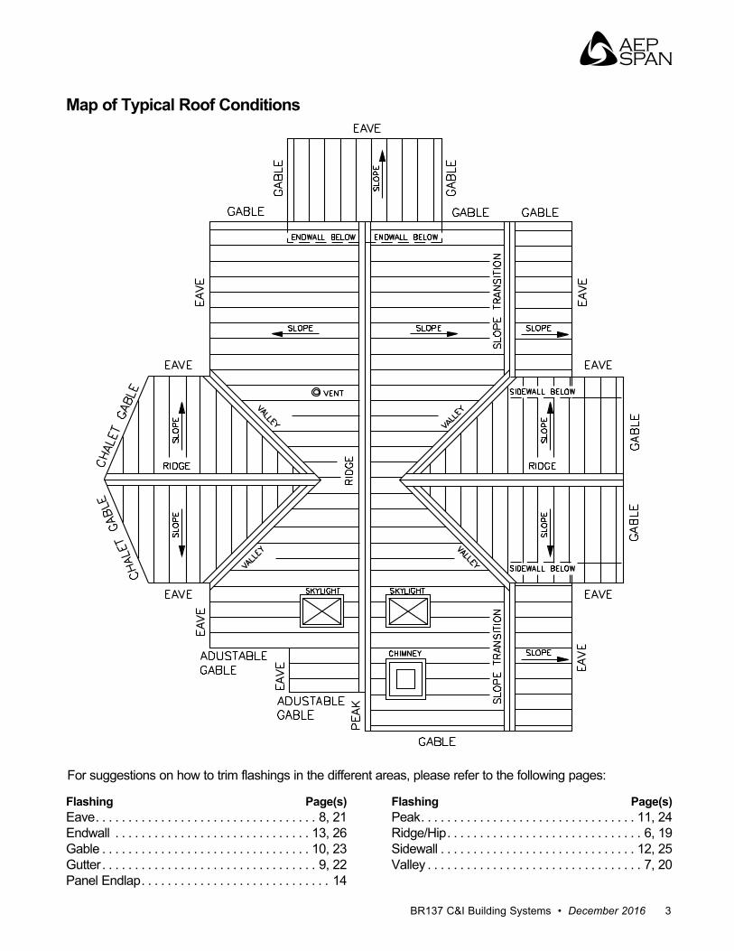
For suggestions on how to trim flashings in the different areas, please refer to the following pages:
Flashing Page(s)Eave . . . . . . . . . . . . . . . . . . . . . . . . . . . . . . . . . . 8, 21Endwall . . . . . . . . . . . . . . . . . . . . . . . . . . . . . . 13, 26Gable . . . . . . . . . . . . . . . . . . . . . . . . . . . . . . . . 10, 23Gutter . . . . . . . . . . . . . . . . . . . . . . . . . . . . . . . . . 9, 22Panel Endlap . . . . . . . . . . . . . . . . . . . . . . . . . . . . . 14
Flashing Page(s)Peak . . . . . . . . . . . . . . . . . . . . . . . . . . . . . . . . . 11, 24Ridge/Hip . . . . . . . . . . . . . . . . . . . . . . . . . . . . . . 6, 19Sidewall . . . . . . . . . . . . . . . . . . . . . . . . . . . . . . 12, 25Valley . . . . . . . . . . . . . . . . . . . . . . . . . . . . . . . . . 7, 20
Map of Typical Roof Conditions
Commercial & Industrial Building SystemsInstallation, Flashings & Details Guide
4 www.aepspan.com
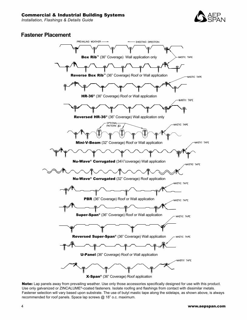
Fastener Placement
Note: Lap panels away from prevailing weather. Use only those accessories specifically designed for use with this product. Use only galvanized or ZINCALUME®-coated fasteners. Isolate roofing and flashings from contact with dissimilar metals. Fastener selection will vary based upon substrate . The use of butyl mastic tape along the sidelaps, as shown above, is always recommended for roof panels . Space lap screws @ 18” o .c . maximum .
Box Rib™ (36” Coverage) Wall application only
Reverse Box Rib™ (36” Coverage) Roof or Wall application
HR-36® (36” Coverage) Roof or Wall application
Reversed HR-36® (36” Coverage) Wall application only
Mini-V-Beam (32” Coverage) Roof or Wall application
Nu-Wave® Corrugated (342⁄3”coverage) Wall application
Nu-Wave® Corrugated (32” Coverage) Roof application
PBR (36” Coverage) Roof or Wall application
Super-Span® (36” Coverage) Roof or Wall application
Reversed Super-Span® (36” Coverage) Wall application
U-Panel (36” Coverage) Roof or Wall application
X-Span® (36” Coverage) Roof application
BR137 C&I Building Systems • December 2016 5
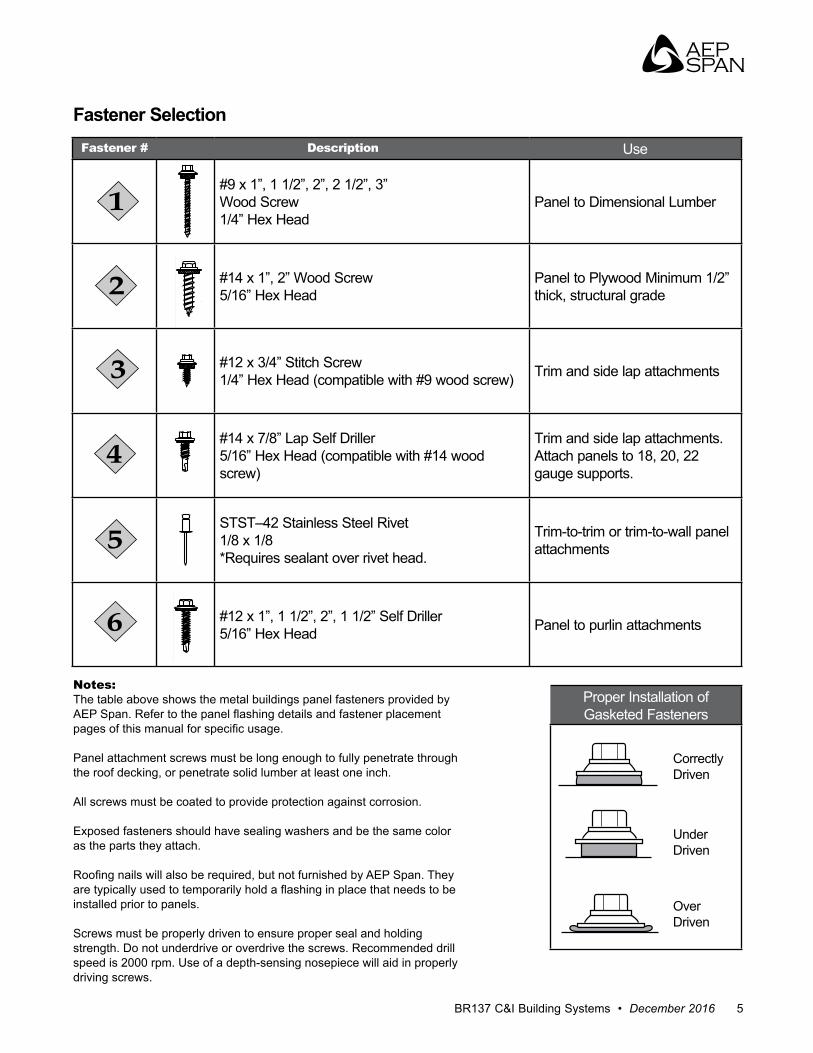
Fastener # Description Use
#9 x 1”, 1 1/2”, 2”, 2 1/2”, 3”Wood Screw1/4” Hex Head
Panel to Dimensional Lumber
#14 x 1”, 2” Wood Screw5/16” Hex Head
Panel to Plywood Minimum 1/2” thick, structural grade
#12 x 3/4” Stitch Screw1/4” Hex Head (compatible with #9 wood screw) Trim and side lap attachments
#14 x 7/8” Lap Self Driller5/16” Hex Head (compatible with #14 wood screw)
Trim and side lap attachments .Attach panels to 18, 20, 22 gauge supports .
STST–42 Stainless Steel Rivet1/8 x 1/8*Requires sealant over rivet head.
Trim-to-trim or trim-to-wall panel attachments
#12 x 1”, 1 1/2”, 2”, 1 1/2” Self Driller5/16” Hex Head Panel to purlin attachments
Fastener Selection
Notes: The table above shows the metal buildings panel fasteners provided by AEP Span. Refer to the panel flashing details and fastener placement pages of this manual for specific usage.
Panel attachment screws must be long enough to fully penetrate through the roof decking, or penetrate solid lumber at least one inch .
All screws must be coated to provide protection against corrosion .
Exposed fasteners should have sealing washers and be the same color as the parts they attach .
Roofing nails will also be required, but not furnished by AEP Span. They are typically used to temporarily hold a flashing in place that needs to be installed prior to panels .
Screws must be properly driven to ensure proper seal and holding strength . Do not underdrive or overdrive the screws . Recommended drill speed is 2000 rpm . Use of a depth-sensing nosepiece will aid in properly driving screws .
Proper Installation of Gasketed Fasteners
CorrectlyDriven
UnderDriven
OverDriven
Commercial & Industrial Building SystemsInstallation, Flashings & Details Guide
6 www.aepspan.com
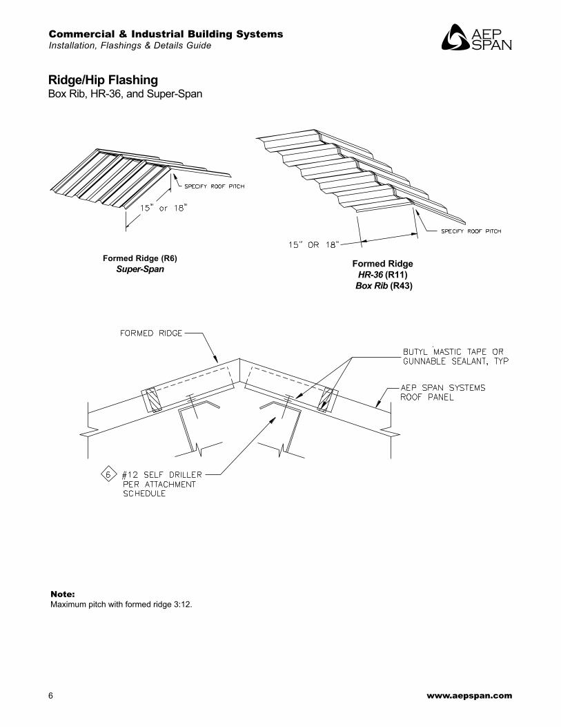
Ridge/Hip FlashingBox Rib, HR-36, and Super-Span
Formed Ridge (R6)Super-Span Formed Ridge
HR-36 (R11) Box Rib (R43)
Note:Maximum pitch with formed ridge 3:12 .
BR137 C&I Building Systems • December 2016 7
*
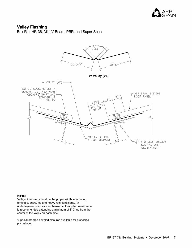
Valley FlashingBox Rib, HR-36, Mini-V-Beam, PBR, and Super-Span
W-Valley (V6)
Note:Valley dimensions must be the proper width to account for slope, snow, ice and heavy rain conditions . An underlayment such as a rubberized cold-applied membrane is recommended extending a minimum of 3’-0” up from the center of the valley on each side .
*Special ordered beveled closures available for a specific pitch/slope .
Commercial & Industrial Building SystemsInstallation, Flashings & Details Guide
8 www.aepspan.com
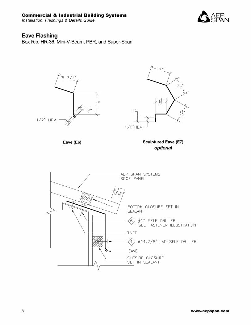
Eave FlashingBox Rib, HR-36, Mini-V-Beam, PBR, and Super-Span
Eave (E6) Sculptured Eave (E7)optional
BR137 C&I Building Systems • December 2016 9
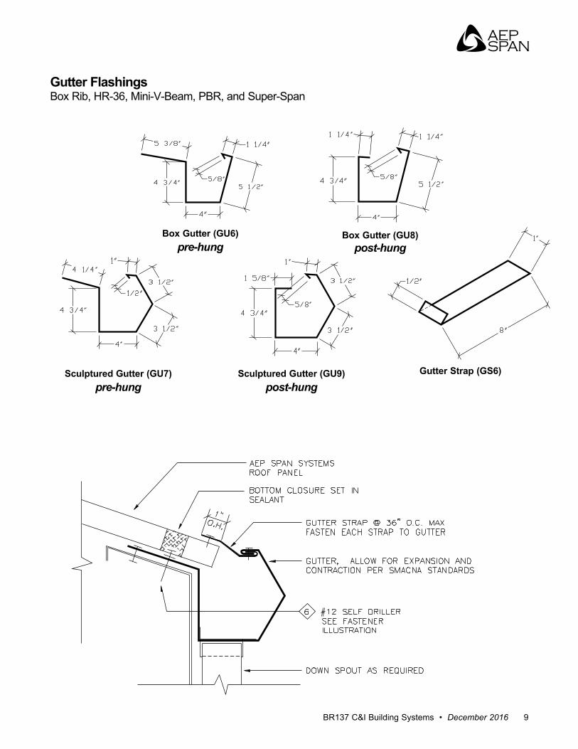
Gutter FlashingsBox Rib, HR-36, Mini-V-Beam, PBR, and Super-Span
Box Gutter (GU6)pre-hung
Sculptured Gutter (GU7)pre-hung
Gutter Strap (GS6)Sculptured Gutter (GU9)post-hung
Box Gutter (GU8)post-hung
Commercial & Industrial Building SystemsInstallation, Flashings & Details Guide
10 www.aepspan.com
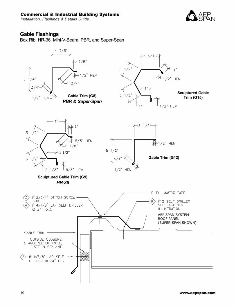
Gable FlashingsBox Rib, HR-36, Mini-V-Beam, PBR, and Super-Span
AEP SPAN SYSTEMROOF PANEL(SUPER-SPAN SHOWN)
1"
1 1/2”
Gable Trim (G8)PBR & Super-Span
Sculptured Gable Trim (G15)
Sculptured Gable Trim (G9)HR-36
Gable Trim (G12)
BR137 C&I Building Systems • December 2016 11
1/2" HEM
1/2" HEM
5-1/2"(VARIES)
5"(VARIES)
1/2"
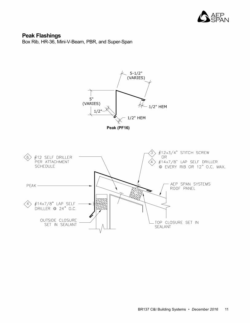
Peak FlashingsBox Rib, HR-36, Mini-V-Beam, PBR, and Super-Span
Peak (PF16)

Commercial & Industrial Building SystemsInstallation, Flashings & Details Guide
12 www.aepspan.com
Sidewall FlashingsBox Rib, HR-36, Mini-V-Beam, PBR, and Super-Span
RIVET ORPAN HEAD SCREW
-
Sidewall (SW7)PBR & Super-Span
Sidewall (SW8)
BR137 C&I Building Systems • December 2016 13
4 1/2"6"
1/2" HEM
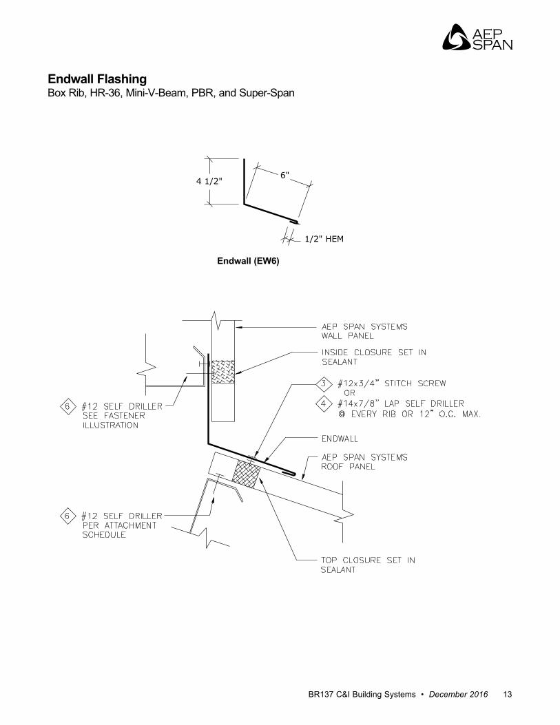
Endwall FlashingBox Rib, HR-36, Mini-V-Beam, PBR, and Super-Span
Endwall (EW6)
Commercial & Industrial Building SystemsInstallation, Flashings & Details Guide
14 www.aepspan.com
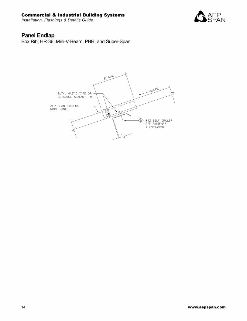
Panel EndlapBox Rib, HR-36, Mini-V-Beam, PBR, and Super-Span

BR137 C&I Building Systems • December 2016 15
Wall DetailsWindow/Door Trim
3 7/8"3 7/8" 3 1/2"
3 1/2" 3 3/4"
C-Metal (C-6)PBR & Super-Span
Jamb Trim (J6)PBR & Super-Span
C-Metal (C12)Mini -V-Beam
C-Metal (C-13)Nu-Wave & U-Panel
C-Metal (C11)Box Rib & HR-36
Commercial & Industrial Building SystemsInstallation, Flashings & Details Guide
16 www.aepspan.com
4 1/8"
1 5/8"
3/4"
1/2" HEM
-
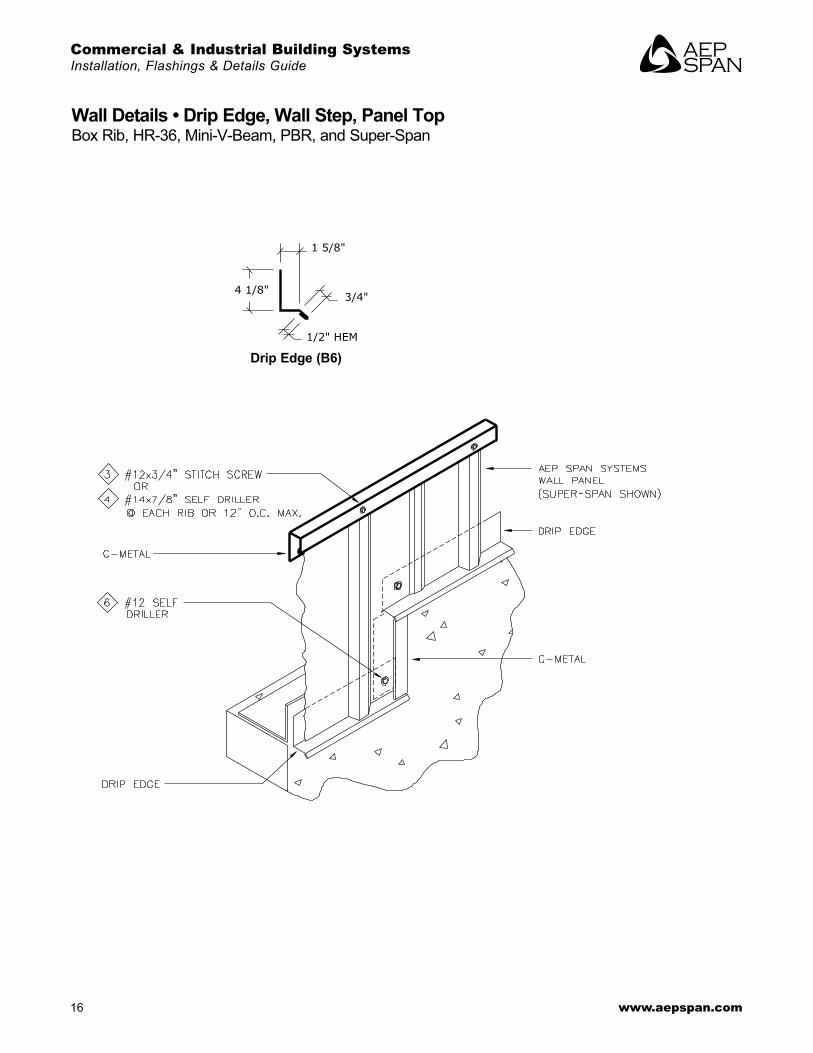
Wall Details • Drip Edge, Wall Step, Panel TopBox Rib, HR-36, Mini-V-Beam, PBR, and Super-Span
Drip Edge (B6)
BR137 C&I Building Systems • December 2016 17
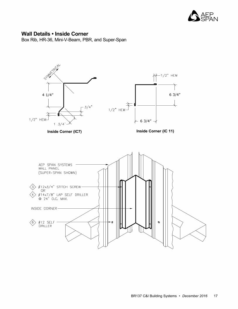
Wall Details • Inside CornerBox Rib, HR-36, Mini-V-Beam, PBR, and Super-Span
4 1/4”
6 3/4”
6 3/4”
-
Inside Corner (IC7) Inside Corner (IC 11)
Commercial & Industrial Building SystemsInstallation, Flashings & Details Guide
18 www.aepspan.com
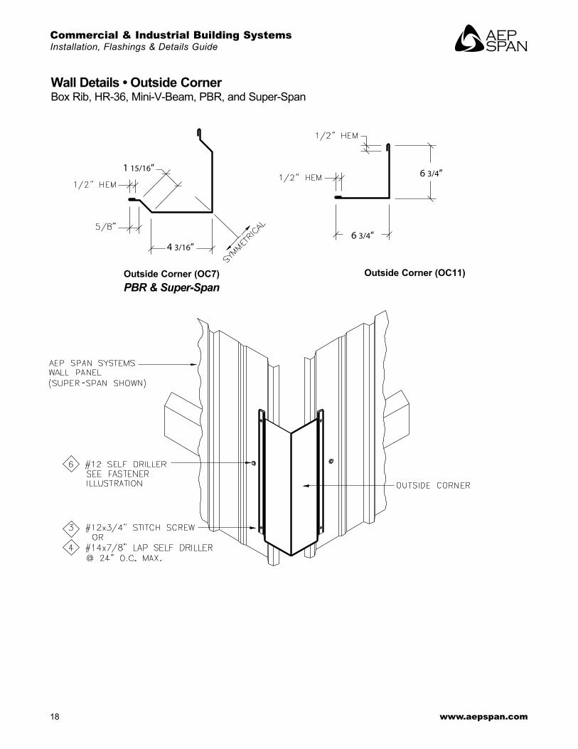
Wall Details • Outside CornerBox Rib, HR-36, Mini-V-Beam, PBR, and Super-Span
1 15/16”
4 3/16”6 3/4”
6 3/4”
-
Outside Corner (OC7)PBR & Super-Span
Outside Corner (OC11)
BR137 C&I Building Systems • December 2016 19
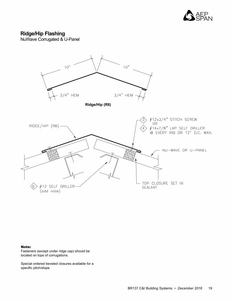
Ridge/Hip FlashingNuWave Corrugated & U-Panel
Ridge/Hip (R8)
Note: Fasteners (except under ridge cap) should be located on tops of corrugations .
Special ordered beveled closures available for a specific pitch/slope.
Commercial & Industrial Building SystemsInstallation, Flashings & Details Guide
20 www.aepspan.com
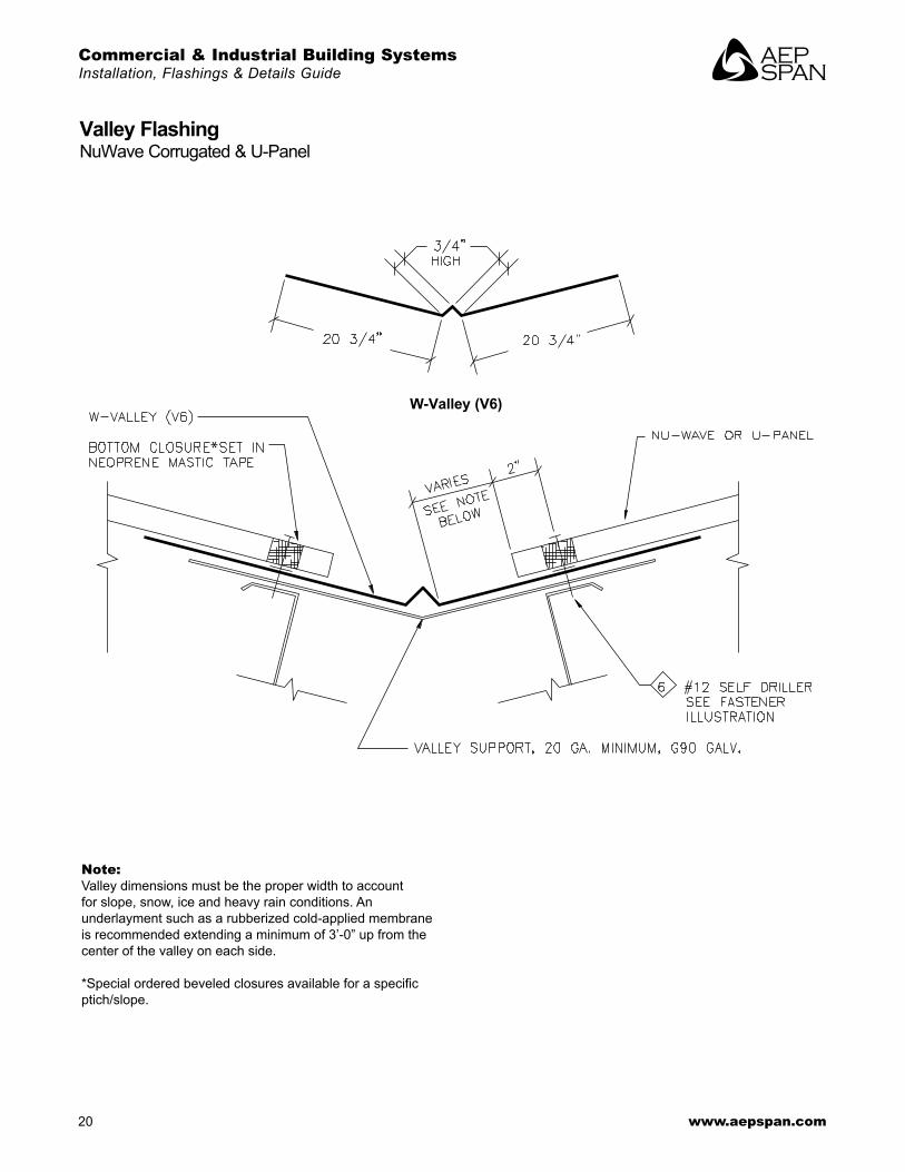
Valley FlashingNuWave Corrugated & U-Panel
Note:Valley dimensions must be the proper width to account for slope, snow, ice and heavy rain conditions . An underlayment such as a rubberized cold-applied membrane is recommended extending a minimum of 3’-0” up from the center of the valley on each side .
*Special ordered beveled closures available for a specific ptich/slope .
*
W-Valley (V6)
BR137 C&I Building Systems • December 2016 21
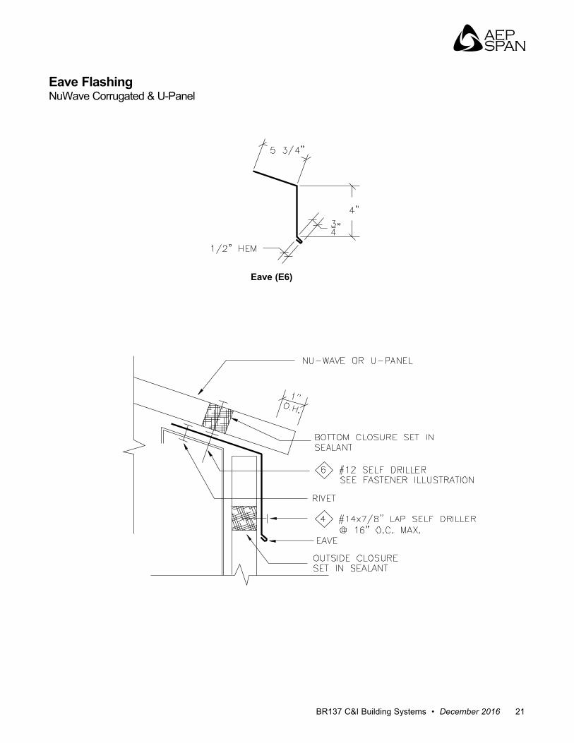
Eave FlashingNuWave Corrugated & U-Panel
Eave (E6)
Commercial & Industrial Building SystemsInstallation, Flashings & Details Guide
22 www.aepspan.com
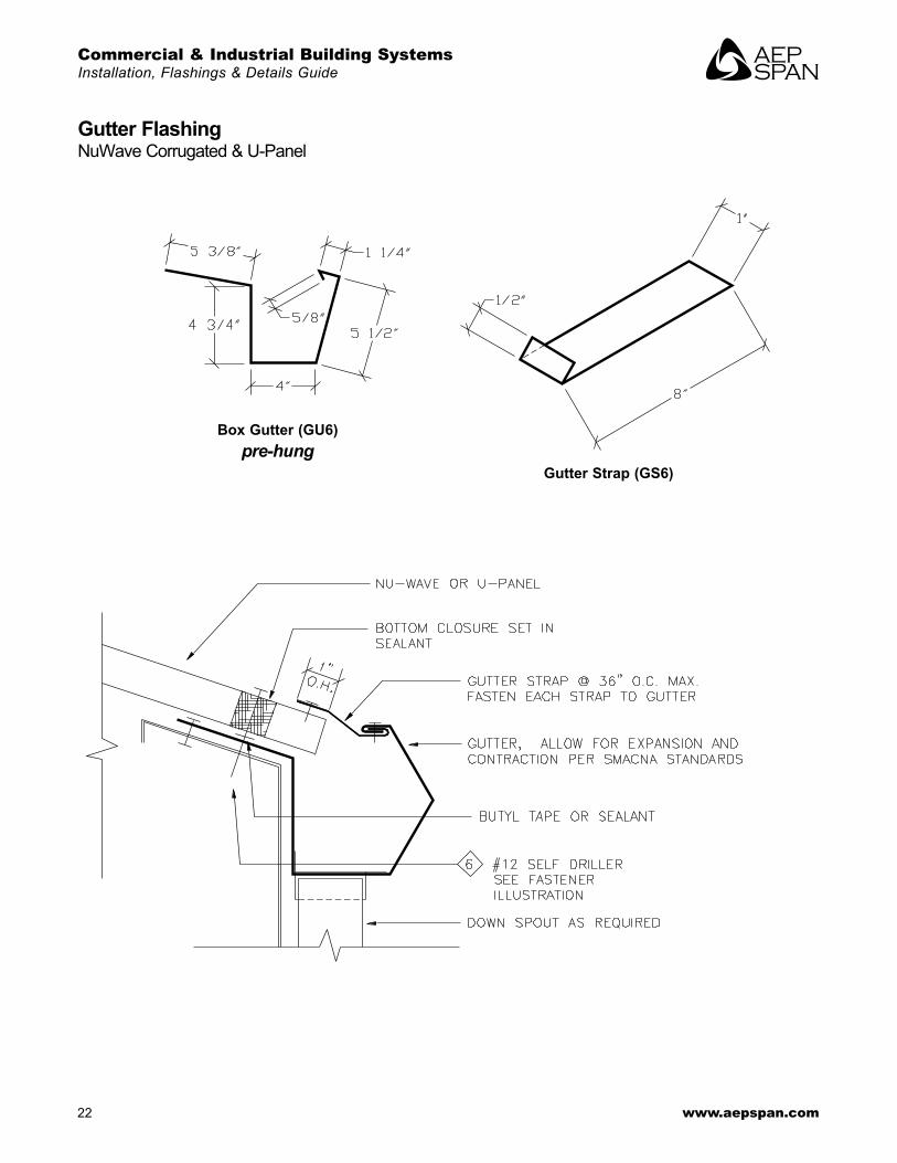
Gutter FlashingNuWave Corrugated & U-Panel
Box Gutter (GU6)pre-hung
Gutter Strap (GS6)
BR137 C&I Building Systems • December 2016 23
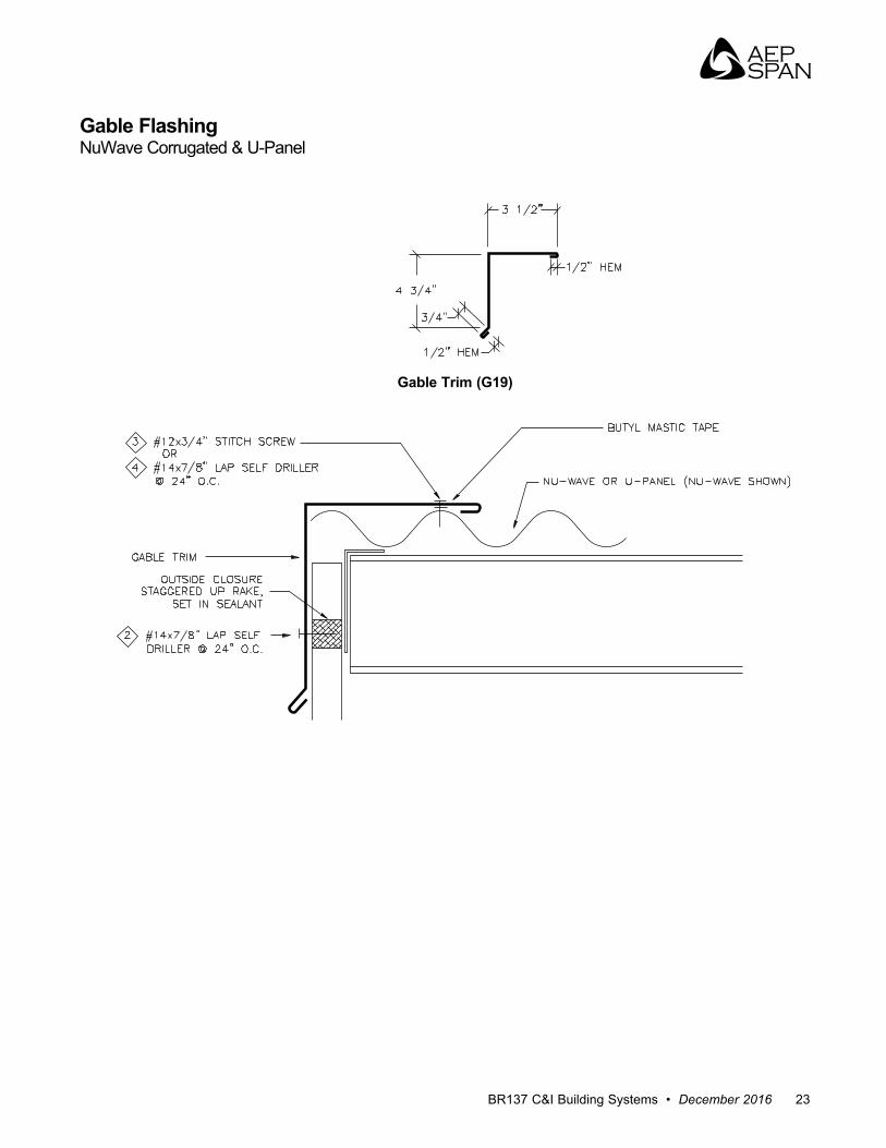
Gable FlashingNuWave Corrugated & U-Panel
Gable Trim (G19)
Commercial & Industrial Building SystemsInstallation, Flashings & Details Guide
24 www.aepspan.com
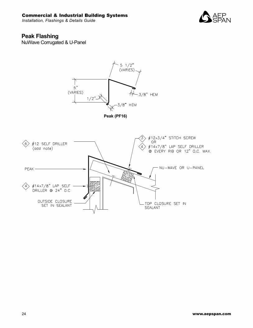
Peak FlashingNuWave Corrugated & U-Panel
Peak (PF16)

BR137 C&I Building Systems • December 2016 25
Sidewall FlashingNuWave Corrugated & U-Panel
Sidewall (SW8)
Commercial & Industrial Building SystemsInstallation, Flashings & Details Guide
26 www.aepspan.com
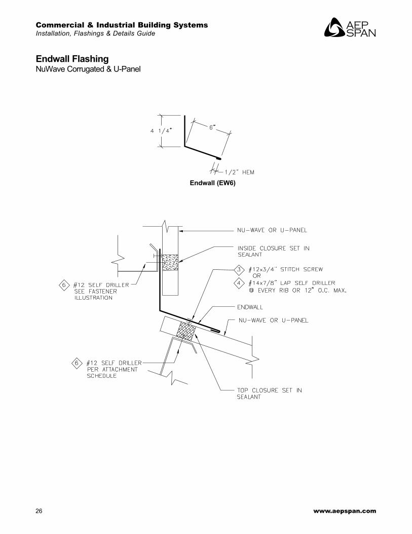
Endwall FlashingNuWave Corrugated & U-Panel
Endwall (EW6)
BR137 C&I Building Systems • December 2016 27
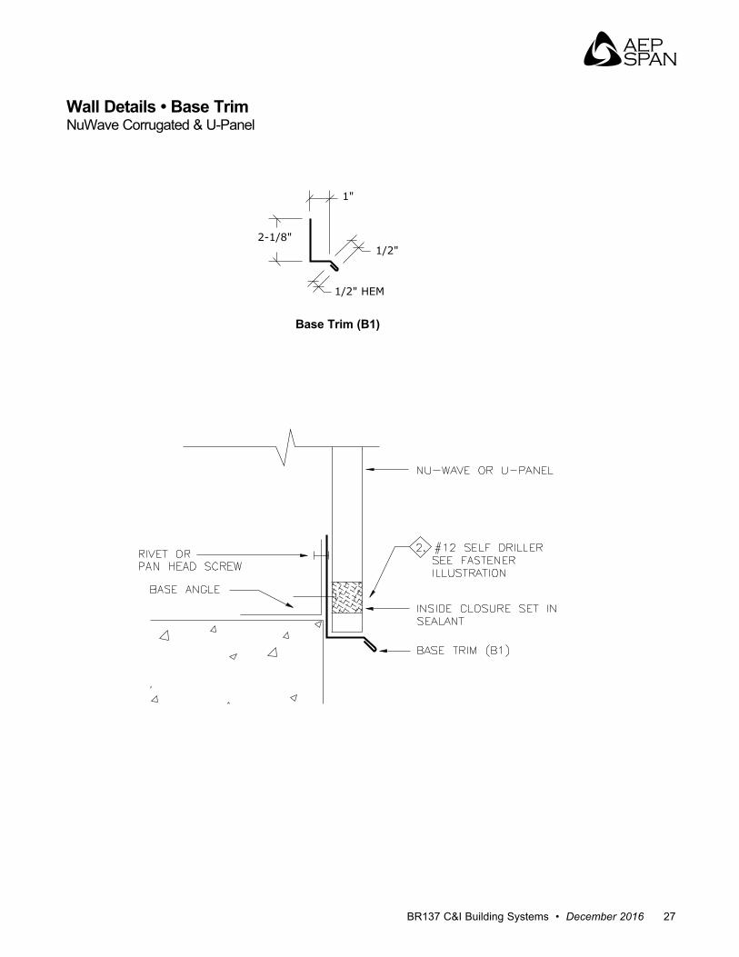
1/2" HEM
1/2"
1"
2-1/8"
Wall Details • Base TrimNuWave Corrugated & U-Panel
Base Trim (B1)
Commercial & Industrial Building SystemsInstallation, Flashings & Details Guide
28 www.aepspan.com
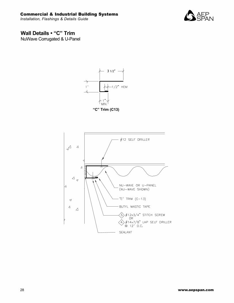
3 1/2”
Wall Details • “C” TrimNuWave Corrugated & U-Panel
“C” Trim (C13)
BR137 C&I Building Systems • December 2016 29
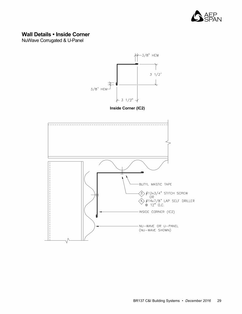
Wall Details • Inside CornerNuWave Corrugated & U-Panel
Inside Corner (IC2)
Commercial & Industrial Building SystemsInstallation, Flashings & Details Guide
30 www.aepspan.com
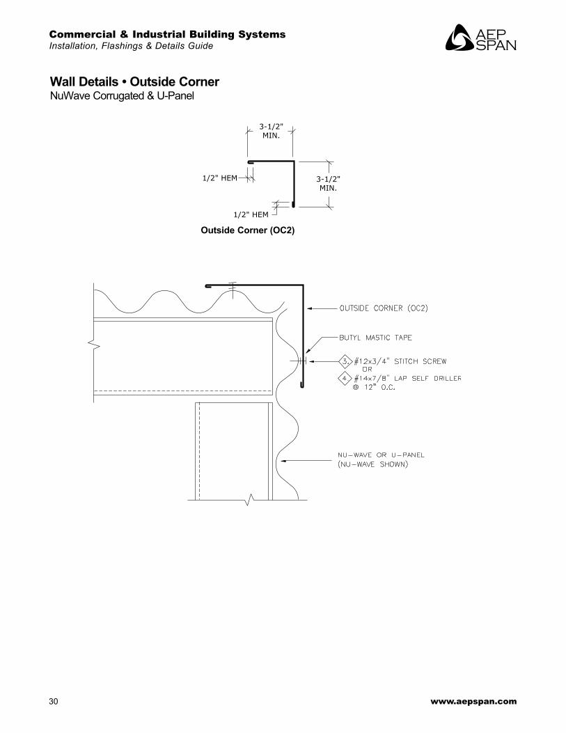
1/2" HEM
1/2" HEM
3-1/2"MIN.
3-1/2"MIN.
Wall Details • Outside CornerNuWave Corrugated & U-Panel
Outside Corner (OC2)
BR137 C&I Building Systems • December 2016 31
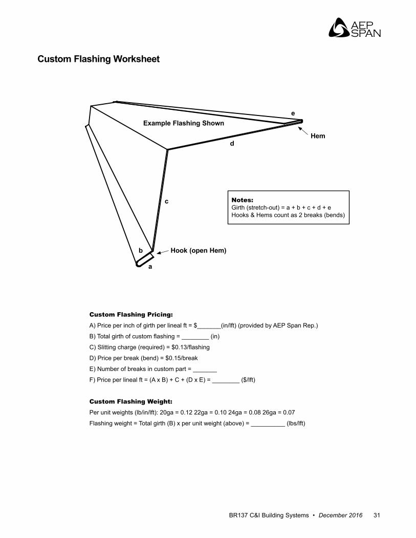
Custom Flashing Worksheet
Notes: Girth (stretch-out) = a + b + c + d + eHooks & Hems count as 2 breaks (bends)
Custom Flashing Pricing:
A) Price per inch of girth per lineal ft = $_______(in/lft) (provided by AEP Span Rep .)
B) Total girth of custom flashing = ________ (in)
C) Slitting charge (required) = $0.13/flashing
D) Price per break (bend) = $0 .15/break
E) Number of breaks in custom part = _______
F) Price per lineal ft = (A x B) + C + (D x E) = ________ ($/lft)
Custom Flashing Weight:
Per unit weights (lb/in/lft): 20ga = 0 .12 22ga = 0 .10 24ga = 0 .08 26ga = 0 .07
Flashing weight = Total girth (B) x per unit weight (above) = __________ (lbs/lft)
Example Flashing Shown
Hem
Hook (open Hem)
e
b
c
d
a
Commercial & Industrial Building SystemsInstallation, Flashings & Details Guide
32 www.aepspan.com