Embed Size (px)
Citation preview
44
MAIN FEATURES 8 analogue inputs with sensor supply for any sensor
and signal type
· Charge, IEPE, Voltage, Strain, Torque, Temperature…
Two versions in speed and resolution:
· SIRIUSi-HS-CA: 16 bit, 1 MS/s for high speed engines
· SIRIUSi-CA: 24 bit, 200 kS/s for low rpm diesel engines
Direct connection of any rpm sensor:
InCar (e.g. 60-2), Encoder, CDM+Trg
1 isolated high speed CAN bus interface
Expandable to higher channel count
Interface to Test-bed and INCA™
Multiple data interfaces CAN, FlexRay, Counter, GPS,
Video...
Simultaneous online analysis of
· Torsional and rotational vibration
· Order tracking
· Electrical power
· Combustion noise
· Sound power
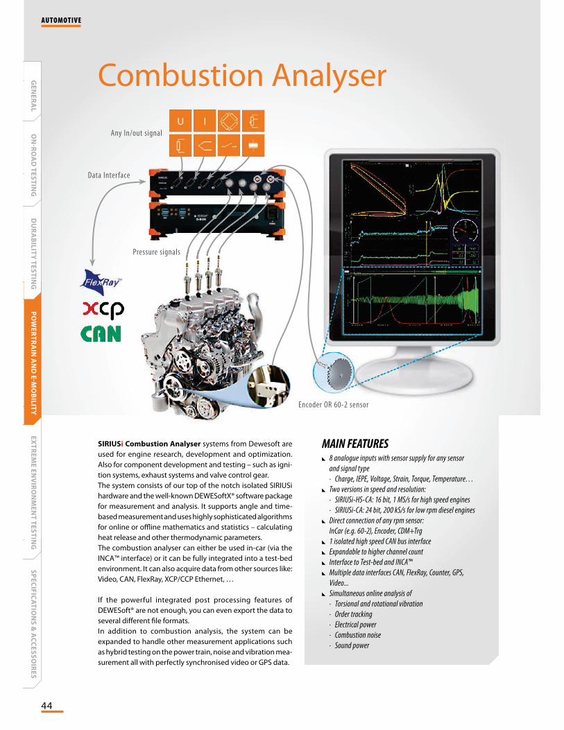
Combustion Analyser
SIRIUSi Combustion Analyser systems from Dewesoft are
used for engine research, development and optimization.
Also for component development and testing – such as igni-
tion systems, exhaust systems and valve control gear.
The system consists of our top of the notch isolated SIRIUSi
hardware and the well-known DEWESoftX® software package
for measurement and analysis. It supports angle and time-
based measurement and uses highly sophisticated algorithms
for online or offline mathematics and statistics – calculating
heat release and other thermodynamic parameters.
The combustion analyser can either be used in-car (via the
INCA™ interface) or it can be fully integrated into a test-bed
environment. It can also acquire data from other sources like:
Video, CAN, FlexRay, XCP/CCP Ethernet, …
If the powerful integrated post processing features of
DEWESoft® are not enough, you can even export the data to
several different file formats.
In addition to combustion analysis, the system can be
expanded to handle other measurement applications such
as hybrid testing on the power train, noise and vibration mea-
surement all with perfectly synchronised video or GPS data.
Encoder OR 60-2 sensor
Any In/out signal
Pressure signals
Data Interface
essure signals
AUTOMOTIVE
SP
EC
IFIC
AT
ION
S &
AC
CE
SS
OIR
ES
EX
TR
EM
E E
NV
IRO
NM
EN
T T
ES
TIN
GP
OW
ER
TR
AIN
AN
D E
-MO
BIL
ITY
DU
RA
BIL
ITY
TE
ST
ING
ON
-RO
AD
TE
ST
ING
GE
NE
RA
L
45
Combustion analysis is a standard application for all
research, development and calibration tasks of a com-
bustion engine and development of exhaust gas after
treatment. Combustion analysis is already required from
the beginning of a prototype: e.g. for friction testing or
in research for basic particle or emission analysis.
Exact identification of the top dead centre and a cali-
brated and compensated measurement chain are key to
accurate measurement results. Combustion analysis is
often used on a chassis dyno or even for the prototype
within the driveability calibration procedure to optimize
engine and vehicle behaviour.
On the engine test bed combustion analysis is a stan-
dard tool to calculate and visualise relevant physical
parameters from the combustion engine and to moni-
tor and protect the unit under test. Different commu-
nication protocols to the control room via Ethernet or
RS-232 are supported: e.g. Tornado, AVL PUMA Open.
Analogue output channels are of course also supported.
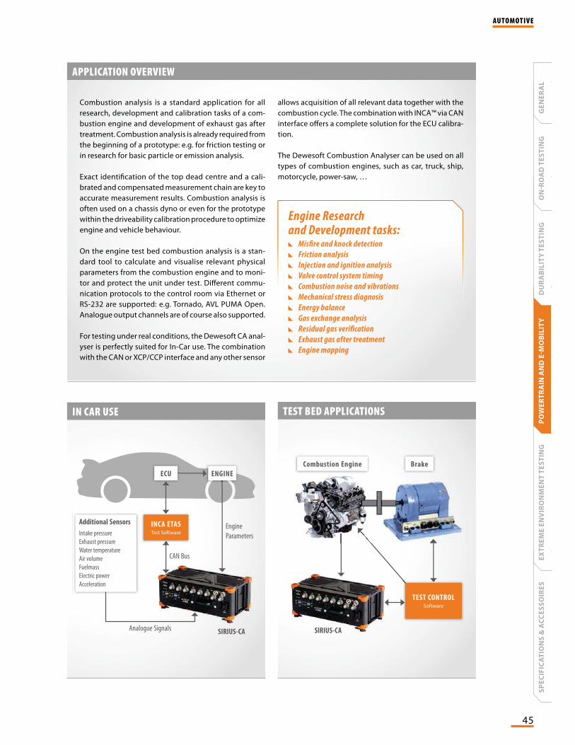
For testing under real conditions, the Dewesoft CA anal-
yser is perfectly suited for In-Car use. The combination
with the CAN or XCP/CCP interface and any other sensor
allows acquisition of all relevant data together with the
combustion cycle. The combination with INCA™ via CAN
interface offers a complete solution for the ECU calibra-
tion.
The Dewesoft Combustion Analyser can be used on all
types of combustion engines, such as car, truck, ship,
motorcycle, power-saw, …
IN CAR USE TEST BED APPLICATIONS
Analogue Signals
CAN Bus
Engine
Parameters
SIRIUS-CA
Additional Sensors
Intake pressure
Exhaust pressure
Water temperature
Air volume
Fuelmass
Electric power
Acceleration
INCA ETASTest Software
ENGINEECU
SIRIUS-CASIRIUS-CA
TEST CONTROLSoftware
Combustion Engine Brake
APPLICATION OVERVIEW
Engine Research and Development tasks:
Misfire and knock detection
Friction analysis
Injection and ignition analysis
Valve control system timing
Combustion noise and vibrations
Mechanical stress diagnosis
Energy balance
Gas exchange analysis
Residual gas verification
Exhaust gas after treatment
Engine mapping
AUTOMOTIVE
GE
NE
RA
LO
NR
OA
D T
ES
TIN
GD
UR
AB
ILIT
Y T
ES
TIN
GP
OW
ER
TR
AIN
AN
D E
MO
BIL
ITY
EX
TR
EM
E E
NV
IRO
NM
EN
T T
ES
TIN
GS
PE
CIF
ICA
TIO
NS
& A
CC
ES
SO
IRE
S
46
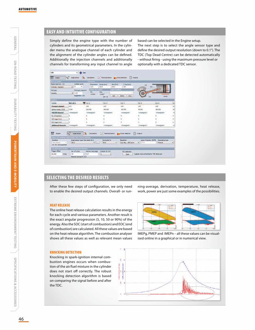
Simply define the engine type with the number of
cylinders and its geometrical parameters. In the cylin-
der menu the analogue channel of each cylinder and
the alignment of the cylinder angles can be defined.
Additionally the injection channels and additionally
channels for transforming any input channel to angle
EASY AND INTUITIVE CONFIGURATION
based can be selected in the Engine setup.
The next step is to select the angle sensor type and
define the desired output resolution (down to 0.1°). The
TDC (Top Dead Centre) can be detected automatically
- without firing - using the maximum pressure level or
optionally with a dedicated TDC sensor.
After these few steps of configuration, we only need
to enable the desired output channels. Overall- or run-
SELECTING THE DESIRED RESULTS
ning-average, derivation, temperature, heat release,
work, power are just some examples of the possibilities.
HEAT RELEASE
The online heat release calculation results in the energy
for each cycle and various parameters. Another result is
the exact angular progression (5, 10, 50 or 90%) of the
energy. Also the SOC (start of combustion) and EOC (end
of combustion) are calculated. All these values are based
on the heat release algorithm. The combustion analyser
shows all these values as well as relevant mean values
KNOCKING DETECTION
Knocking in spark-ignition internal com-
bustion engines occurs when combus-
tion of the air/fuel mixture in the cylinder
does not start off correctly. The robust
knocking detection algorithm is based
on comparing the signal before and after
the TDC.
IMEPg, PMEP and IMEPn – all these values can be visual-
ised online in a graphical or in numerical view.
AUTOMOTIVE
SP
EC
IFIC
AT
ION
S &
AC
CE
SS
OIR
ES
EX
TR
EM
E E
NV
IRO
NM
EN
T T
ES
TIN
GP
OW
ER
TR
AIN
AN
D E
-MO
BIL
ITY
DU
RA
BIL
ITY
TE
ST
ING
ON
-RO
AD
TE
ST
ING
GE
NE
RA
L

47
SELECTING THE DESIRED RESULTS
KNOCKING DETECTION
The combustion noise option allows the
measurement of noise level caused by an
internal combustion engine during opera-
tion. The CA-noise must be calculated in the
time domain. First the value is scaled from
bar to Pascal. This is followed by the U-filter,
which simulates the transfer function of the
engine (1. and 2. filter in the overview).
MATHEMATICS AND STATISTICS
The physical channels can be
supplemented with the online
mathematics like statistics, fil-
ters, FFT, alarm conditions and
many others.
Online calculated values may
be used for optimisation or
other automated procedures.
With the new post-processing
feature of DEWESoft X®, all the
powerful mathematical and
analysis functions can now also
be used for the already stored
data (offline mode).
GROUP NAME DESCRIPTION
Pressures MAX P Peak pressure value
MAP P Pos Peak pressure position [degrees]
Pressure Current pressure cycle
Derivates MAX D Peak pressure derivate value
MAX D POS Peak pressure derivate position
Derivate Current pressure derivative
Volume Volume Cylinder volume curve
Zero correction P CORR Zero correction factor for pressures
MEP PI Work delivered to the piston over engine cycle
PIH Work performed by cylinder gasses on the piston during compression and expansion
PIL Work performed by the piston during exhaust and induction
GROUP NAME DESCRIPTION
Work, Power,Torque
Work Work [Joule]
Power Power [kWh]
Torque Torque [Nm]
Heat release I5 Position of the heat release at 5% [deg]
I10 Position of the heat release at 10% [deg]
I50 Position of the heat release at 50% [deg]
I90 Position of the heat release at 90% [deg]
IXX Position of the heat release at user defined % [deg]
SOC Start of combustion [deg]
EOC End of combustion [deg]
TQ Heat release during combustion
TI Integrated heat release
Knocking KF Knocking factor
Injection SOI Start of injection
EOI End of injection
SUMMARY OF CALCULATED RESULTS
The overview below shows the power of the Dewesoft
CA module. Most of them are available as cylinder and
engine averaged results as well.
AUTOMOTIVE
GE
NE
RA
LO
NR
OA
D T
ES
TIN
GD
UR
AB
ILIT
Y T
ES
TIN
GP
OW
ER
TR
AIN
AN
D E
MO
BIL
ITY
EX
TR
EM
E E
NV
IRO
NM
EN
T T
ES
TIN
GS
PE
CIF
ICA
TIO
NS
& A
CC
ES
SO
IRE
S
48
DEWESOFT® POSTPROCESSING
In DEWESoft® X calculations (i.e. mathematical channels)
can be added to datafiles after the measurement has been
finished. It can even resample the settings of the encoder or
of the engine. Those parameters are then recalculated and
saved in the datafile.
This powerful feature allows to delay CPU intense calcula-
tions until after the measurement has finished. i.e. during the
measurement you only store the relevant raw measurement
data. And after the measurement is done, you can run all the
mathematical calculations on a powerful PC in your office.
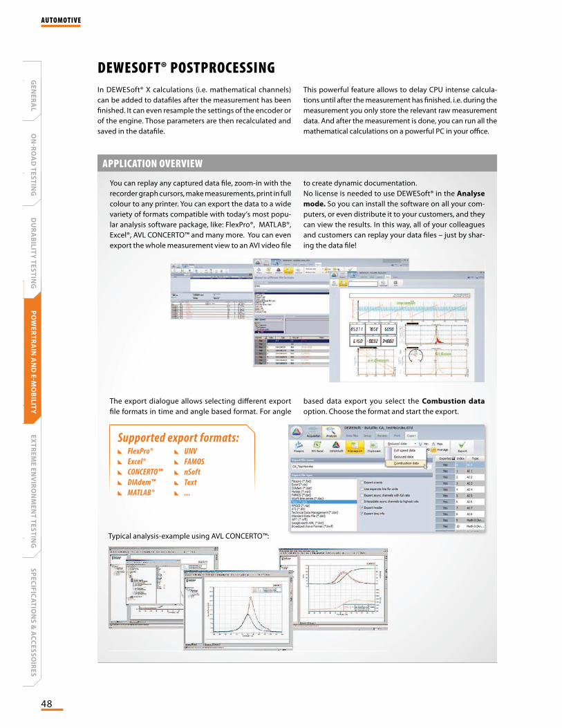
You can replay any captured data file, zoom-in with the
recorder graph cursors, make measurements, print in full
colour to any printer. You can export the data to a wide
variety of formats compatible with today‘s most popu-
lar analysis software package, like: FlexPro®, MATLAB®,
Excel®, AVL CONCERTO™ and many more. You can even
export the whole measurement view to an AVI video file
to create dynamic documentation.
No license is needed to use DEWESoft® in the Analyse
mode. So you can install the software on all your com-
puters, or even distribute it to your customers, and they
can view the results. In this way, all of your colleagues
and customers can replay your data files – just by shar-
ing the data file!
APPLICATION OVERVIEW
The export dialogue allows selecting different export
file formats in time and angle based format. For angle
based data export you select the Combustion data
option. Choose the format and start the export.
Supported export formats: FlexPro®
Excel®
CONCERTO™
DIAdem™
MATLAB®
UNV
FAMOS
nSoft
Text
...
Typical analysis-example using AVL CONCERTO™:
AUTOMOTIVE
SP
EC
IFIC
AT
ION
S &
AC
CE
SS
OIR
ES
EX
TR
EM
E E
NV
IRO
NM
EN
T T
ES
TIN
GP
OW
ER
TR
AIN
AN
D E
-MO
BIL
ITY
DU
RA
BIL
ITY
TE
ST
ING
ON
-RO
AD
TE
ST
ING
GE
NE
RA
L
49
CASYSTEM
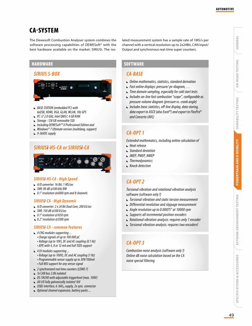
BASE STATION (embedded PC) with 6xUSB, HDMI, VGA, GLAN, WLAN, 1Hz GPS
PC: i7 2.0 GHz, Intel QM57, 4 GB RAM Storage : 128 GB removable SSD Including DEWESoft™ X Professional Edition and Windows® 7 Ultimate version (multilang. support) 9-36VDC supply
The Dewesoft Combustion Analyser system combines the
software processing capabilities of DEWESoft® with the
best hardware available on the market: SIRIUSi. The iso-
lated measurement system has a sample rate of 1MS/s per
channel with a vertical resolution up to 2x24Bit, CAN Input/
Output and synchronous real-time super counters.
SOFTWAREHARDWARE
SIRIUS S-BOX
SIRIUSi-HS-CA - High Speed
A/D converter: 16 Bit; 1 MS/sec SNR: 89 dB @100 kHz BW 0.1° resolution @6000 rpm and 8 channels
SIRIUSi-CA - High Dynamic
A/D converter: 2 x 24 Bit Dual Core; 200 kS/sec SNR: 150 dB @100 kS/sec 0.1° resolution @1650 rpm
0.2° resolution @3300 rpm
SIRIUSi-CA - common features
4 CHG modules supporting ... • Charge signals of up to 100 000 pC • Voltage (up to 10V), DC and AC coupling (0.1 Hz) • IEPE with 4, 8 or 12 mA and full TEDS support
4 LV modules supporting ... • Voltage (up to 100V), DC and AC coupling (1 Hz) • Programmable sensor supply up to 30V/100mA • Full MSI support for any sensor signal
2 synchronized real time counters (LEMO 7) 1x CAN bus 2.0b isolated DS-TACHO with adjustable triggerlevel (max. 100V) All I/O fully galvanically isolated 1kV USB2 interface, 6-36VDC supply, 2x sync. connector Optional channel expansion, battery packs ...
SIRIUSi-HS-CA or SIRIUSi-CA
CA-BASE
Online mathematics, statistics, standard derivation
Fast online displays: pressure/ pv-diagram, …
Time domain sampling, especially for cold start tests
Includes on-line fast combustion “scope”, configurable as
pressure-volume diagram (pressure vs. crank angle)
Includes basic statistics, off-line display, data storing,
data export to ASCII (also Excel®) and export to FlexPro®
and Concerto (AVL)
CA-OPT 1
Extended mathematics, including online calculation of
Heat release
Standard deviation
IMEP, PMEP, NMEP
Thermodynamics
Knock detection
CA-OPT 2
Torsional vibration and rotational vibration analysis
software (software only !)
Torsional vibration and static torsion measurement
Differential revolution and slippage measurement
Angle resolution up to 0.00075° at 10000 rpm
Supports all incremental position encoders
Rotational vibration analysis: requires only 1 encoder
Torsional vibration analysis: requires two encoders!
CA-OPT 3
Combustion noise analysis (software only !)
Online dB noise calculation based on the CA
noise special filtering
AUTOMOTIVE
GE
NE
RA
LO
NR
OA
D T
ES
TIN
GD
UR
AB
ILIT
Y T
ES
TIN
GP
OW
ER
TR
AIN
AN
D E
MO
BIL
ITY
EX
TR
EM
E E
NV
IRO
NM
EN
T T
ES
TIN
GS
PE
CIF
ICA
TIO
NS
& A
CC
ES
SO
IRE
S