Embed Size (px)
Citation preview
1Immunity Tests: Combination Wave Test System
Combination Wave
Test System
Imm
unit
y Te
sts
Brief Overview of Phenomena. . . . . . . . . . . . . . . . 2
Applicable Standards . . . . . . . . . . . . . . . . . . . 3
Test System Overview. . . . . . . . . . . . . . . . . . . 4
Generator Specifications. . . . . . . . . . . . . . . . . . 8
Accessories and Options. . . . . . . . . . . . . . . . . 12
Software . . . . . . . . . . . . . . . . . . . . . . . 14
EMC PARTNER’s Product Range . . . . . . . . . . . . . . 15
2 Immunity Tests: Combination Wave Test System
The most frequent cause of damage in industrial electronic systems is overvoltages, caused either by switching actions in the equipment itself or by atmospheric discharges such as lightning. If the interference source is in the same circuit as the electronic equipment, the transfer impedance is low and the impulse takes a current form. If the interference is from some external source, the transfer impedance will be higher and a voltage impulse results. To simulate both these conditions, a Combination Wave Generator (CWG) is designed to deliver a voltage impulse into an open circuit and a current impulse into a short circuit. This is also known as a “Hybrid” generator. Combi-nation Wave Generators have a virtual impedance (open circuit voltage / short circuit current) of 2 ohms.
Power network transients can be modified by the cable properties so that in a well protected domestic or commercial environment, the impulse energy has an oscillatory form. This is known as a “Ring wave”.
EMC Partner Combination Wave and Ring wave Generators are used to simulate transient (impulses) in the public power supply network.
Brief Overview of Phenomena
Combination wave and Ring wave testing is performed on power or communication networks, which require Coupling and Decoupling Networks (CDNs) to superimpose the impulses and provide protection for auxiliary equipment that is not part of the test setup. Synchronization of the impulse with power frequencies is also required
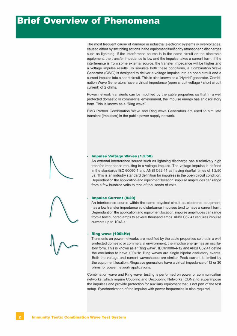
- Impulse Voltage Waves (1.2/50) An external interference source such as lightning discharge has a relatively high
transfer impedance resulting in a voltage impulse. The voltage impulse is defined in the standards IEC 60060-1 and ANSI C62,41 as having rise/fall times of 1,2/50 μs. This is an industry standard definition for impulses in the open circuit condition. Dependant on the application and equipment location, impulse amplitudes can range from a few hundred volts to tens of thousands of volts.
- Impulse Current (8/20) An interference source within the same physical circuit as electronic equipment,
has a low transfer impedance so disturbance impulses tend to have a current form. Dependant on the application and equipment location, impulse amplitudes can range from a few hundred amps to several thousand amps. ANSI C62.41 requires impulse currents up to 10kA.s.
- Ring wave (100kHz) Transients on power networks are modified by the cable properties so that in a well
protected domestic or commercial environment, the impulse energy has an oscilla-tory form. This is known as a “Ring wave”. IEC61000-4-12 and ANSI C62.41 define the oscillation to have 100kHz. Ring waves are single bipolar oscillatory events. Both the voltage and current waveshapes are similar. Peak current is limited by the equipment location. Ringwave generators have a virtual impedance of 12 or 30 ohms for power network applications.

3Immunity Tests: Combination Wave Test System
American National Standards Institute (ANSI)ANSI C62.41 (1991): IEEE Recommended Practice on Surge Voltages in Low Voltage AC Power Circuits..
Applicable Standards
International Electrotechnical Committee (IEC)IEC 61000-4-5 Ed 2: Electromagnetic compatibility (EMC) - Testing and measurement techniques - Surge immunity test.
IEC61000-4-12 Ed 2: Electromagnetic compatibility (EMC) - Testing and measurement techniques - Ring wave immunity test.
International Telecommunications Union (ITU)K.44 (2008): Resistibility tests for telecommunications equipment exposed to overvolt-ages and overcurrents - Basic recommendation
K.20 (2008): Resistibility of telecommunication equipment installed in a telecommunica-tions centre to overvoltages and overcurrents
K.21 (2008): Resistibility of telecommunication equipment installed in customer premises to overvoltages and overcurrents.
4 Immunity Tests: Combination Wave Test System
Test System Feature- Up to 24000V impulse voltage- Up to 12000A impulse current- Combined Surge and Ring wave generator combinations- Power CDNs up to 100A per phase- Automatic coupling path selection- Accurate and stable phase angle synchronisation- Telecom and dataline CDNs- Impulse parameters defined at CDN output- Parameter ramp feature- Electronic polarity change- Semiconductor switches - Generators use patented EMC PARTNER impulse modules- Integrated emergency stop switch- Safety circuit design to protect operators- Compact designs- High degree of automation without software- 2 year warranty
User BenefitsThe technical excellence and many unique features of combination and ring wave generators translate directly into benefits for the user:
- Impulse repeatability pulse to pulse- Reproducible test results between locations- Automation reduces operator error- Combined coupler for all EMC power tests- Operator safety ensured- Reduced test time- ANSI coupling path compatible- Save operator time with the automated test routines and test report facility- Unparalleled reliability and system up-time
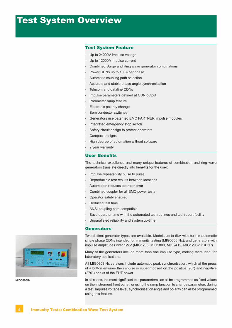
Generators Two distinct generator types are available. Models up to 6kV with built-in automatic single phase CDNs intended for immunity testing (MIG0603INx), and generators with impulse amplitudes over 12kV (MIG1206, MIG1809, MIG2412, MIG1206-1P & 3P).
Many of the generators include more than one impulse type, making them ideal for laboratory applications.
All MIG0603INx versions include automatic peak synchronisation, which at the press of a button ensures the impulse is superimposed on the positive (90°) and negative (270°) peaks of the EUT power.
In all cases, the most significant test parameters can all be programmed as fixed values on the instrument front panel, or using the ramp function to change parameters during a test. Impulse voltage level, synchronisation angle and polarity can all be programmed using this feature.
Test System Overview
MIG0603IN

5Immunity Tests: Combination Wave Test System
- MIG0603IN S The “classic” combination wave generator for IEC, EN and ANSI applications up
to 6kV/3kA. The integrated single phase CDN operates with EUT power up to 280V/16Aac and 110V/16Adc. Three applications can be programmed with the MIG0603IN; CWG 1.2/50us 2 ohm, CWG 1.2/50us 2+10 ohm and CWG 1.2/50us IEC. There is a direct output for data line testing as well as the CDN output.
- MIG0603IN1 S-R A combination wave generator with Ringwave for IEC, EN and ANSI applications up
to 6kV. The integrated single phase CDN operates with EUT power up to 280V/16Aac and 110V/16Adc. Six applications can be programmed with the MIG0603IN1; CWG 1.2/50us 2 ohm, CWG 1.2/50us 2+10 ohm, CWG 1.2/50us IEC, ringwave 12 ohms, ringwave 30 ohms and ringwave 200 ohms. There is a direct output for data line testing as well as the CDN output.
- MIG0603IN3 S-R-T A compact generator with three distinct waveforms for IEC, EN, ANSI and ITU tel-
ecom applications up to 6kV. A combination wave, ringwave and 10/700us impulse can be applied through the integrated single phase CDN or for telecom applications using the direct output to the external CDN-UTP. The integrated single phase CDN operates with EUT power up to 280V/16Aac and 110V/16Adc. The addition of a 10/700us impulse makes this unit ideal for basic level telecom applications.
- MIG0603IN4 R A pure ringwave generator with three outputs at 12, 30 and 200 ohms. This genera-
tor is appropriate for IEC, EN and ANSI applications. The integrated single phase CDN operates with EUT power up to 280V/16Aac and 110V/16Adc.
- MIG0603-3P100 S The “flag ship” Combination Wave generator with fully automatic 100A three phase
CDN and optional EFT/Burst. Specially designed for higher current EUTs. The fully automatic CDN outputs are placed at the correct height for floor standing EUTs to fulfill both the IEC61000-4-5 and IEC61000-4-4 requirements. A high degree of automation, enables this generator to be programmed for a complete test suite including voltage ramping, phase angle ramping and coupling path selection. -
- MIG1206-1P A 12kV Combination wave generator with integrated and automatic single phase
CDN. EUT current is 32Aac and 25Adc.
- MIG1206-3P Similar to the MIG1206-1P except that a fully automatic three phase CDN is inte-
grated with the combination wave generator. EUT current through the CDN is rated at 32A per phase.
- MIG1206 A pure combination wave generator, MIG1206 can be applied for component testing
using the TC-MIG24 test cabinet accessory. The high voltage outputs are conven-iently located on the generator top. For applications requiring connection to AC or DC power, the CDN-MIG12-32 can be used. Coupling path selection is manual on the front panel using safety high voltage connectors.
- MIG1809 Like the MIG1206, MIG1809 is a combination wave generator conceived for direct
connection to components. The high voltage outputs on top of the instrument are protected by the TC-MIG24 test cabinet which is integrated into the generator safety circuit.
- MIG2412 This, is the highest level stand alone combination wave generator from EMC PART-
NER. It is also designed for component testing with the high voltage outputs on top and the TC-MIG24 test cabinet.
MIG0603-3P100 S
MIG1206-1P
MIG0603IN4
MIG0603IN3

6 Immunity Tests: Combination Wave Test System
Flowcharts
Combination wave up to 6kV
TEMA TEST MANAGERcustomized solution
DSO Optioncontrol TEK DSO
CDN2000-06-32
MIG0603-3P100
EUT
MF1000-1MF1000-2
MIG0603IN S MIG0603IN1 S-R
MIG0603IN3 S-T-R
CN-MIG12-80C1
CDN-UTP
MIG0603IN4 R
CDN-A-3P100-480 FS
CDN-A-3P100-690-FS
Combination wave up to 12kV
MIG1206-1P
TEMA TEST MANAGERcustomized solution
DSO Optioncontrol TEK DSO
TC-MIG24
MIG1206-3P
EUT
EUT POWER
CDN-MIG12-80C1
7Immunity Tests: Combination Wave Test System
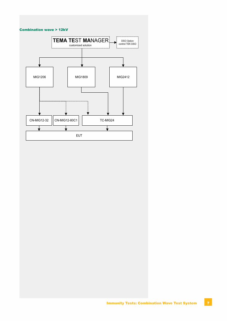
Combination wave > 12kV
MIG1809
TEMA TEST MANAGERcustomized solution
DSO Optioncontrol TEK DSO
TC-MIG24
MIG2412
EUT
CN-MIG12-32
MIG1206
CN-MIG12-80C1
8 Immunity Tests: Combination Wave Test System
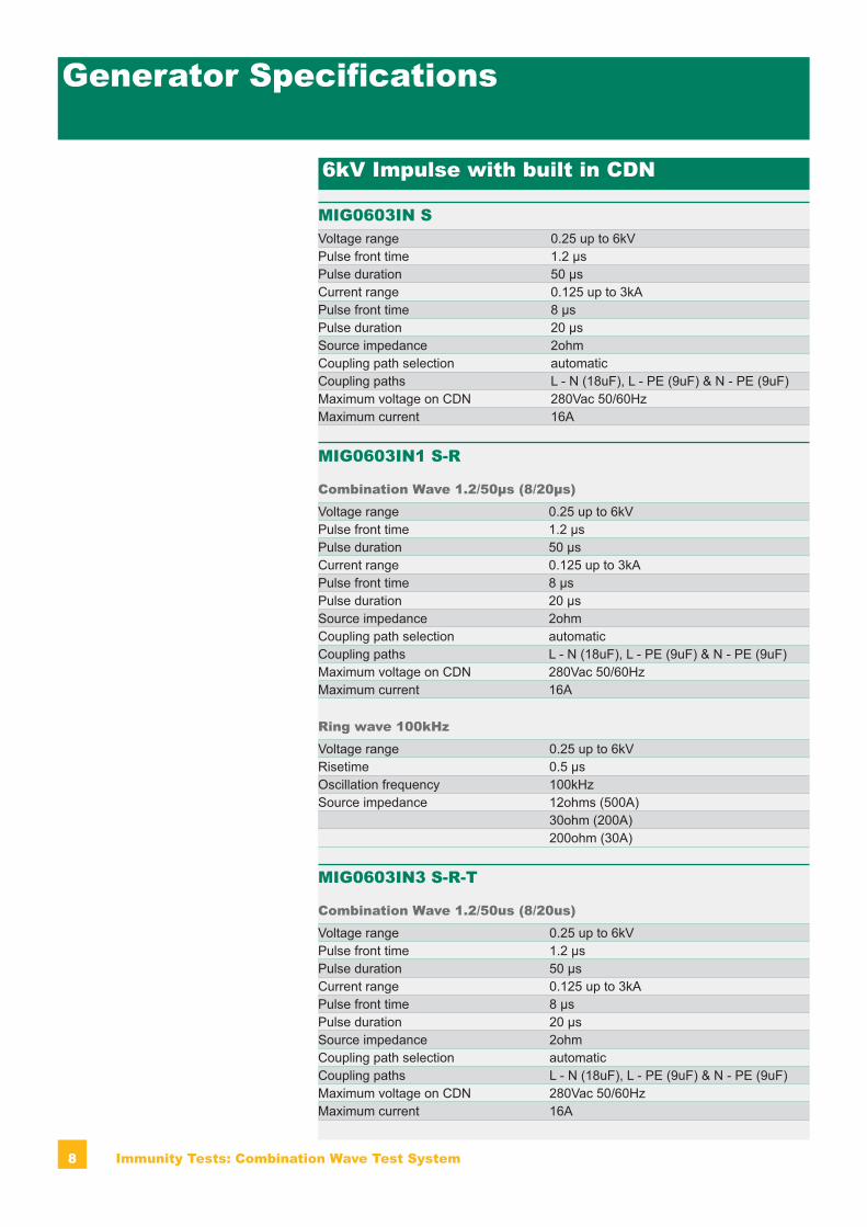
Generator Specifications
6kV Impulse with built in CDN
MIG0603IN SVoltage range 0.25 up to 6kVPulse front time 1.2 μsPulse duration 50 μsCurrent range 0.125 up to 3kAPulse front time 8 μsPulse duration 20 μsSource impedance 2ohmCoupling path selection automaticCoupling paths L - N (18uF), L - PE (9uF) & N - PE (9uF)Maximum voltage on CDN 280Vac 50/60HzMaximum current 16A
MIG0603IN1 S-R
Combination Wave 1.2/50μs (8/20μs)Voltage range 0.25 up to 6kVPulse front time 1.2 μsPulse duration 50 μsCurrent range 0.125 up to 3kAPulse front time 8 μsPulse duration 20 μsSource impedance 2ohmCoupling path selection automaticCoupling paths L - N (18uF), L - PE (9uF) & N - PE (9uF)Maximum voltage on CDN 280Vac 50/60HzMaximum current 16A
Ring wave 100kHzVoltage range 0.25 up to 6kVRisetime 0.5 μsOscillation frequency 100kHzSource impedance 12ohms (500A)
30ohm (200A)200ohm (30A)
MIG0603IN3 S-R-T
Combination Wave 1.2/50us (8/20us)Voltage range 0.25 up to 6kVPulse front time 1.2 μsPulse duration 50 μsCurrent range 0.125 up to 3kAPulse front time 8 μsPulse duration 20 μsSource impedance 2ohmCoupling path selection automaticCoupling paths L - N (18uF), L - PE (9uF) & N - PE (9uF)Maximum voltage on CDN 280Vac 50/60HzMaximum current 16A
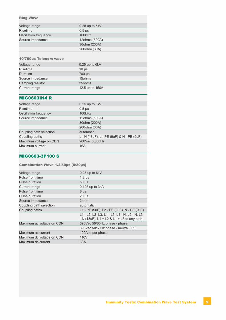
9Immunity Tests: Combination Wave Test System
Ring Wave
Voltage range 0.25 up to 6kVRisetime 0.5 μsOscillation frequency 100kHzSource impedance 12ohms (500A)
30ohm (200A)200ohm (30A)
10/700us Telecom waveVoltage range 0.25 up to 6kVRisetime 10 μsDuration 700 μsSource impedance 15ohmsDamping resistor 25ohmsCurrent range 12.5 up to 150A
MIG0603IN4 RVoltage range 0.25 up to 6kVRisetime 0.5 μsOscillation frequency 100kHzSource impedance 12ohms (500A)
30ohm (200A)200ohm (30A)
Coupling path selection automaticCoupling paths L - N (18uF), L - PE (9uF) & N - PE (9uF)Maximum voltage on CDN 280Vac 50/60HzMaximum current 16A
MIG0603-3P100 S
Combination Wave 1.2/50μs (8/20μs)
Voltage range 0.25 up to 6kVPulse front time 1.2 μsPulse duration 50 μsCurrent range 0.125 up to 3kAPulse front time 8 μsPulse duration 20 μsSource impedance 2ohmCoupling path selection automaticCoupling paths L1 - PE (9uF), L2 - PE (9uF), N - PE (9uF)
L1 - L2, L2 -L3, L1 - L3, L1 - N, L2 - N, L3 - N (18uF), L1 + L2 & L1 + L3 to any path
Maximum ac voltage on CDN 690Vac 50/60Hz phase - phase398Vac 50/60Hz phase - neutral / PE
Maximum ac current 100Aac per phaseMaximum dc voltage on CDN 110VMaximum dc current 63A
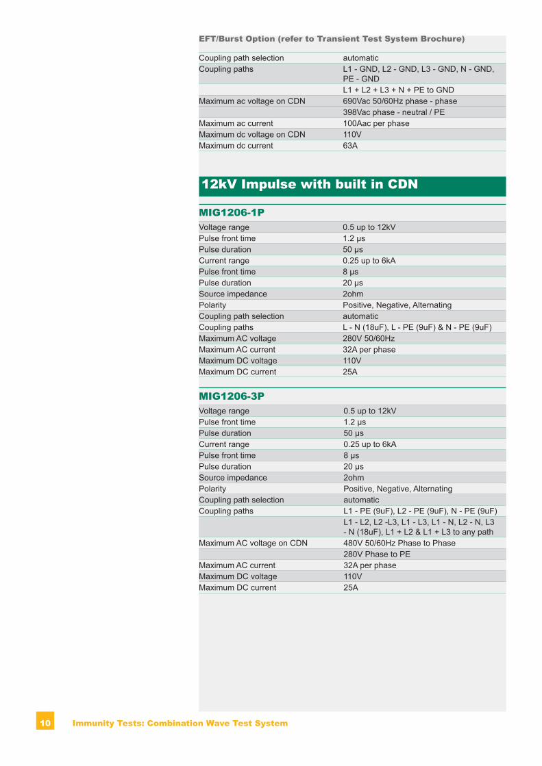
10 Immunity Tests: Combination Wave Test System
EFT/Burst Option (refer to Transient Test System Brochure)
Coupling path selection automaticCoupling paths L1 - GND, L2 - GND, L3 - GND, N - GND,
PE - GNDL1 + L2 + L3 + N + PE to GND
Maximum ac voltage on CDN 690Vac 50/60Hz phase - phase398Vac phase - neutral / PE
Maximum ac current 100Aac per phaseMaximum dc voltage on CDN 110VMaximum dc current 63A
12kV Impulse with built in CDN
MIG1206-1PVoltage range 0.5 up to 12kVPulse front time 1.2 μsPulse duration 50 μsCurrent range 0.25 up to 6kAPulse front time 8 μsPulse duration 20 μsSource impedance 2ohmPolarity Positive, Negative, AlternatingCoupling path selection automaticCoupling paths L - N (18uF), L - PE (9uF) & N - PE (9uF)Maximum AC voltage 280V 50/60HzMaximum AC current 32A per phaseMaximum DC voltage 110VMaximum DC current 25A
MIG1206-3PVoltage range 0.5 up to 12kVPulse front time 1.2 μsPulse duration 50 μsCurrent range 0.25 up to 6kAPulse front time 8 μsPulse duration 20 μsSource impedance 2ohmPolarity Positive, Negative, AlternatingCoupling path selection automaticCoupling paths L1 - PE (9uF), L2 - PE (9uF), N - PE (9uF)
L1 - L2, L2 -L3, L1 - L3, L1 - N, L2 - N, L3 - N (18uF), L1 + L2 & L1 + L3 to any path
Maximum AC voltage on CDN 480V 50/60Hz Phase to Phase280V Phase to PE
Maximum AC current 32A per phaseMaximum DC voltage 110VMaximum DC current 25A
11Immunity Tests: Combination Wave Test System
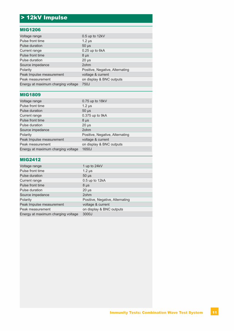
> 12kV Impulse
MIG1206Voltage range 0.5 up to 12kVPulse front time 1.2 μsPulse duration 50 μsCurrent range 0.25 up to 6kAPulse front time 8 μsPulse duration 20 μsSource impedance 2ohmPolarity Positive, Negative, AlternatingPeak Impulse measurement voltage & currentPeak measurement on display & BNC outputsEnergy at maximum charging voltage 750J
MIG1809Voltage range 0.75 up to 18kVPulse front time 1.2 μsPulse duration 50 μsCurrent range 0.375 up to 9kAPulse front time 8 μsPulse duration 20 μsSource impedance 2ohmPolarity Positive, Negative, AlternatingPeak Impulse measurement voltage & currentPeak measurement on display & BNC outputsEnergy at maximum charging voltage 1650J
MIG2412Voltage range 1 up to 24kVPulse front time 1.2 μsPulse duration 50 μsCurrent range 0.5 up to 12kAPulse front time 8 μsPulse duration 20 μsSource impedance 2ohmPolarity Positive, Negative, AlternatingPeak Impulse measurement voltage & currentPeak measurement on display & BNC outputsEnergy at maximum charging voltage 3000J
12 Immunity Tests: Combination Wave Test System
Accessories and Options
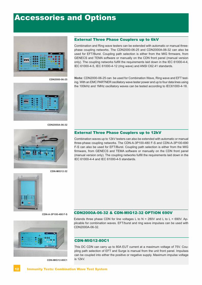
External Three Phase Couplers up to 6kVCombination and Ring wave testers can be extended with automatic or manual three-phase coupling networks. The CDN2000-06-25 and CDN2000A-06-32 can also be used for EFT/Burst. Coupling path selection is either from the MIG firmware, from GENECS and TEMA software or manually on the CDN front panel (manual version only). The coupling networks fulfill the requirements laid down in the IEC 61000-4-4, IEC 61000-4-5, IEC 61000-4-12 (ring wave) and ANSI C62.41 standards.
Note: CDN2000-06-25 can be used for Combination Wave, Ring wave and EFT test-ing. With an EMC PARTNER oscillatory wave tester power and up to four data lines using the 100kHz and 1MHz oscillatory waves can be tested according to IEC61000-4-18.
CDN-MIG12-80C1
External Three Phase Couplers up to 12kVCombination waves up to 12kV testers can also be extended with automatic or manual three-phase coupling networks. The CDN-A-3P100-480 F-S and CDN-A-3P100-690 F-S can also be used for EFT/Burst. Coupling path selection is either from the MIG firmware, from GENECS and TEMA software or manually on the CDN front panel (manual version only). The coupling networks fulfill the requirements laid down in the IEC 61000-4-4 and IEC 61000-4-5 standards.
CDN-MIG12-32
CDN2000A-06-32
CDN2000-06-25
CDN-A-3P100-480 F-S CDN2000A-06-32 & CDN-MIG12-32 OPTION 690VExtends three phase CDN for line voltages L to N = 280V and L to L = 690V. Ap-plicable for combination waves. EFT/burst and ring wave impulses can be used with CDN2000A-06-32.
CDN-MIG12-80C1This DC CDN can carry up to 80A EUT current at a maximum voltage of 75V. Cou-pling path selection of EFT and Surge is manual from the unit front panel. Impulses can be coupled into either the positive or negative supply. Maximum impulse voltage is 12kV.
13Immunity Tests: Combination Wave Test System
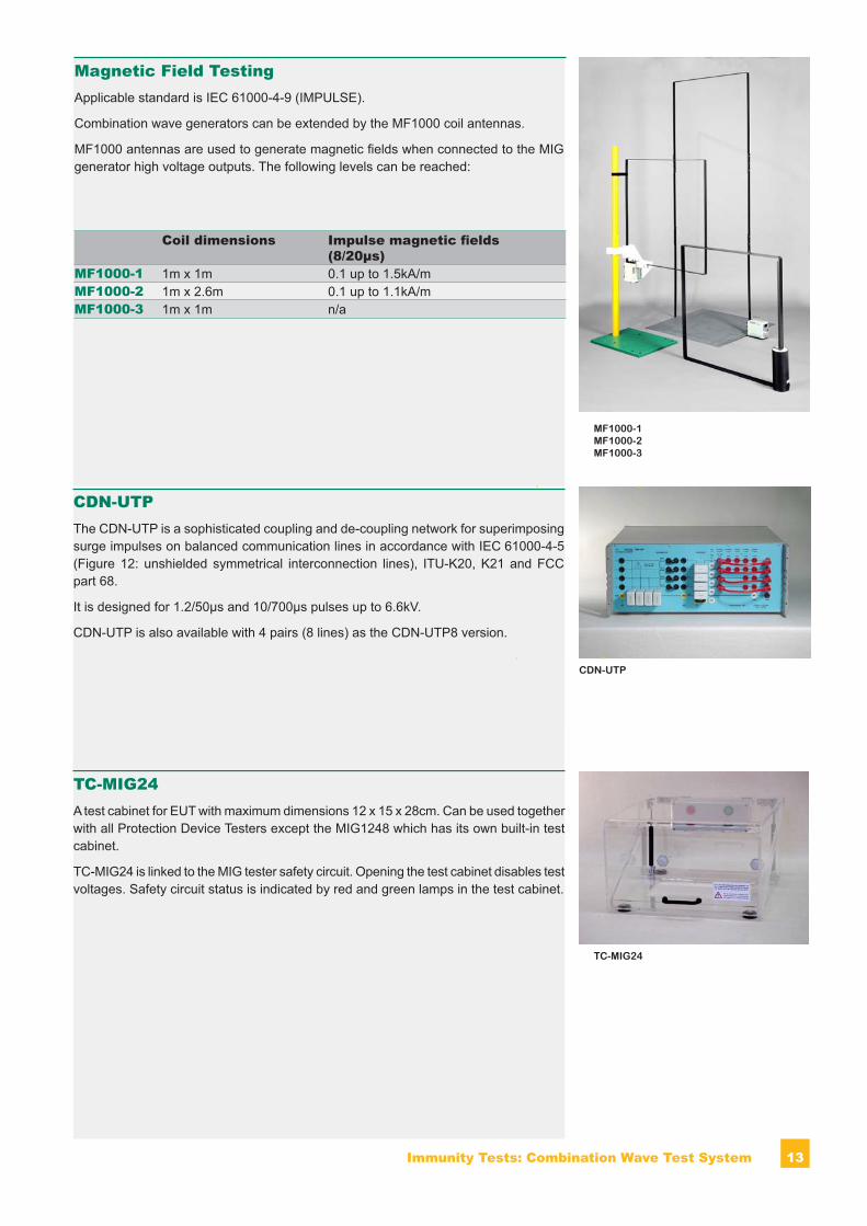
Magnetic Field TestingApplicable standard is IEC 61000-4-9 (IMPULSE).
Combination wave generators can be extended by the MF1000 coil antennas.
MF1000 antennas are used to generate magnetic fields when connected to the MIG generator high voltage outputs. The following levels can be reached:
Coil dimensions Impulse magnetic fields (8/20μs)
MF1000-1 1m x 1m 0.1 up to 1.5kA/mMF1000-2 1m x 2.6m 0.1 up to 1.1kA/mMF1000-3 1m x 1m n/a
MF1000-1 MF1000-2 MF1000-3
TC-MIG24A test cabinet for EUT with maximum dimensions 12 x 15 x 28cm. Can be used together with all Protection Device Testers except the MIG1248 which has its own built-in test cabinet.
TC-MIG24 is linked to the MIG tester safety circuit. Opening the test cabinet disables test voltages. Safety circuit status is indicated by red and green lamps in the test cabinet.
TC-MIG24
CDN-UTPThe CDN-UTP is a sophisticated coupling and de-coupling network for superimposing surge impulses on balanced communication lines in accordance with IEC 61000-4-5 (Figure 12: unshielded symmetrical interconnection lines), ITU-K20, K21 and FCC part 68.
It is designed for 1.2/50μs and 10/700μs pulses up to 6.6kV.
CDN-UTP is also available with 4 pairs (8 lines) as the CDN-UTP8 version.
CDN-UTP
14 Immunity Tests: Combination Wave Test System
Software
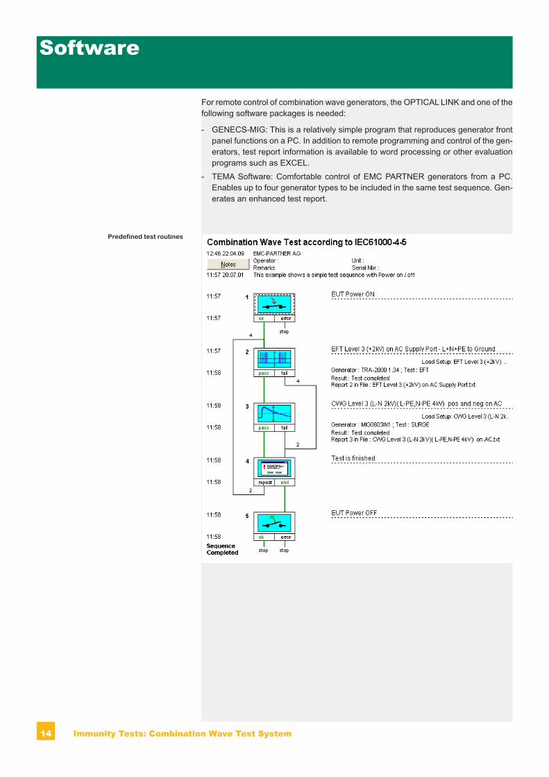
For remote control of combination wave generators, the OPTICAL LINK and one of the following software packages is needed:
- GENECS-MIG: This is a relatively simple program that reproduces generator front panel functions on a PC. In addition to remote programming and control of the gen-erators, test report information is available to word processing or other evaluation programs such as EXCEL.
- TEMA Software: Comfortable control of EMC PARTNER generators from a PC. Enables up to four generator types to be included in the same test sequence. Gen-erates an enhanced test report.
Predefined test routines
15Immunity Tests: Combination Wave Test System
EMC PARTNER’s Product RangeHidden Heading to provoke a TOC entry
EMC PARTNER’s Product RangeThe Largest Range of Impulse Test Equip ment up to 100kA and 100kV.
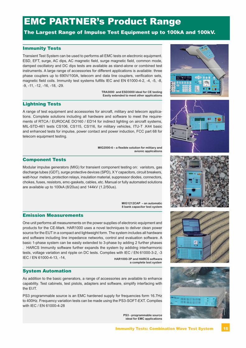
Lightning TestsA range of test equipment and accessories for aircraft, military and telecom applica-tions. Complete solutions including all hardware and software to meet the require-ments of RTCA / EUROCAE DO160 / ED14 for indirect lighting on aircraft systems,MIL-STD-461 tests CS106, CS115, CS116, for military vehicles, ITU-T .K44 basic
rand enhanced tests for impulse, power contact and power induction, FCC part 68 for telecom equipment testing.
Component TestsModular impulse gen er a tors (MIG) for transient com po nent testing on: varistors, gas discharge tubes (GDT), surge pro tec tive devices (SPD), X Y ca pac i tors, cir cuit break ers, watt-hour meters, pro tec tion re lays, in su la tion ma te ri al, sup pres sor di odes, con nec tors,chokes, fus es, re sis tors, emc-gaskets, ca bles, etc. Manual or fully automated solutionsare available up to 100kA (8/20us) and 144kV (1.2/50us).
Emission MeasurementsOne unit per forms all meas ure ments on the power sup plies of elec tron ic equip ment and
rprod ucts for the CE-Mark. HAR1000 uses a novel techniques to deliver clean pow er source for the EUT in a compact and lightweight form. The system includes all hardware
A and software including line im ped ance net works, control and evaluation software. Abasic 1-phase system can be easily extended to 3-phase by adding 2 further phases . HARCS Immunity soft ware further expands the system by addidng interharmonic tests, voltage variation and ripple on DC tests. Com plies with IEC / EN 61000-3-2, -3 IEC / EN 61000-4-13, -14,
Immunity TestsTransient Test System can be used to per forms all EMC tests on elec tron ic equip ment. ESD, EFT, surge, AC dips, AC mag net ic fi eld, surge mag net ic fi eld, com mon mode, damped oscillatory and DC dips tests are available as stand-alone or combined testinstruments. A large range of ac ces so ries for dif fer ent ap pli ca tions is avail a ble: three phase cou plers up to 690V/100A, telecom and data line couplers, ver i fi ca tion sets, magnetic fi eld coils. Immunity test systems fulfi lls IEC and EN 61000-4-2, -4, -5, -8, -9, -11, -12, -16, -18, -29.
MIG2000-6 – a flexible solution for military andavionic applications
MIG1212CAP – an automatic8 bank capacitor test system
System AutomationAs addition to the basic generators, a range of accessories are available to enhance capability. Test cabinets, test pistols, adapters and software, simplify interfacing withthe EUT.
PS3 programmable source is an EMC hardened supply for frequencies form 16.7Hz to 400Hz. Frequency variation tests can be made using the PS3-SOFT-EXT. Complies with IEC / EN 61000-4-28
HAR1000-3P and HARCS softwarea complete test system
PS3 - programmable source ideal for EMC applications
TRA3000 and ESD3000 ideal for CE testing Easily extended to meet other applications
16 Immunity Tests: Combination Wave Test System
For further information please do not hesitate to contact EMC PARTNER’s representa-tive in your region. You will find a complete list of our representatives and a lot of other useful information on our website:
The Headquarters in SwitzerlandEMC PARTNER AG Baselstrasse 160 CH - 4242 Laufen Switzerland
Phone: +41 61 775 20 30 Fax: +41 61 775 20 59 Email: [email protected] Web-Site: www.emc-partner.com
Your local representative
Version May 2010 . Subject to change without notice.
www.emc-partner.com


