Embed Size (px)
Citation preview

Combating Inter-cell Interference in 802.11ac-basedMulti-user MIMO Networks
Hang Yu, Oscar Bejarano, and Lin ZhongDepartment of Electrical and Computer Engineering, Rice University, Houston, TX
{Hang.Yu, obejarano, lzhong}@rice.edu
AbstractIn an 802.11ac-based MU-MIMO network comprised of multiplecells1, inter-cell interference allows only a single AP to serveits clients at the same time, significantly limiting the networkcapacity. In this work, we overcome this limitation by lettingthe APs and clients in interfering cells coordinately cancel theinter-cell interference using their antennas for beamforming. Toachieve such coordinated interference cancellation in a practicalway, we propose a novel two-step optimization. First, withoutrequiring any channel knowledge, each AP and client optimizesthe use of its antennas for either data communication or inter-cellinterference cancellation, in order to maximize the total numberof deliverable streams in the MU-MIMO network. Second, withonly partial channel knowledge, each AP and client optimizes theirbeamforming weights after the optimal antenna usage has beenidentified in the first step. Our solution, CoaCa, integrates thistwo-step optimization into 802.11ac with small modifications andnegligible overhead, allowing each AP and client to locally performthe two-step optimization. Our experimental evaluation indicatesthat for a MU-MIMO network with two cells, by cancellingthe inter-cell interference CoaCa can convert the majority of theexpected number of streams increase (50%-67%) into networkcapacity improvement (41%-52%).
Categories and Subject DescriptorsC.2.1 [COMPUTER-COMMUNICATION NETWORKS]: Net-work Architecture and Design - Wireless Communication
KeywordsInter-cell interference; multi-user MIMO; 802.11ac; CoaCa
1. INTRODUCTIONFor 802.11 networks comprised of multiple cells, inter-cell
interference has become a key factor that limits the network
1We use cell to denote the domain of an access point (AP) and itsassociated clients.
Permission to make digital or hard copies of all or part of this work for personal orclassroom use is granted without fee provided that copies are not made or distributedfor profit or commercial advantage and that copies bear this notice and the full citationon the first page. Copyrights for components of this work owned by others thanACM must be honored. Abstracting with credit is permitted. To copy otherwise, orrepublish, to post on servers or to redistribute to lists, requires prior specific permissionand/or a fee. Request permissions from [email protected]’14, September 7-11, 2014, Maui, Hawaii, USA.Copyright 2014 ACM 978-1-4503-2783-1/14/09 ...$15.00http://dx.doi.org/10.1145/2639108.2639122.
capacity because it prevents the APs in neighboring cells fromserving their clients concurrently. To cancel inter-cell interferencewith beamforming, the interfering AP and client are required to(i) be aware of the channel between them, and (ii) coordinateto determine their duty of cancellation. Yet, neither of the tworequirements is directly supported by existing 802.11 protocols.There have been efforts in supporting them in 802.11n that featuressingle-user MIMO (SU-MIMO). 802.11n+ proposed in [10] seeksto enable concurrent links across multiple cells. n+ cancels theinter-cell interference by (i) letting nodes in one cell overhear thetransmissions from nodes in the other cell to acquire necessarychannel knowledge, and (ii) coordinating nodes in the two cellsby opportunistically starting the concurrent link in the overhearingcell afterwards. Notably, the interference cancellation coordinationin n+ is one-way: nodes in the overhearing cell must use their spareantennas to cancel the inter-cell interference. The number of spareantennas should be no smaller than that of the ongoing streams inthe overheard cell. Since an 802.11n link with SU-MIMO usuallyincludes one or two streams, only one or two spare antennas areneeded for each node in the overhearing cell.
For the newer 802.11ac supporting multi-user MIMO (MU-MIMO), an AP can transmit to multiple, say K (e.g., K=4)clients simultaneously. When a cell is congested with more clientsthan antennas on the AP, the AP delivers a single stream to eachserved client so that the number of streams is equal to the numberof clients, denoted as the multiplexing gain of MU-MIMO. Toincrease the multiplexing gain by starting concurrent streams inthe overhearing cell, n+ would require each AP and client in it tohave at least K spare antennas to cancel the inter-cell interference,which is usually infeasible in practice. The fundamental reasonwhy n+ does not effectively extend to 802.11ac is its one-waycoordination for inter-cell interference cancellation, where nodes inthe overhearing cell have to contribute all the required antennas tosolely carry the burden of cancellation. Our key insight in this workis that when two congested MU-MIMO cells “jointly coordinate,”the number of required antennas on their nodes can be reduced andmore streams can be delivered concurrently.
Let us consider the example in Figure 1. With three antennason each AP and three clients in each cell, n+ only allows a singleAP (AP1 or AP2) to serve its clients at a time, therefore activatingonly up to three streams in the network. Instead of solely relyingon the nodes in one cell to cancel the inter-cell interference likein n+, we do it in the following alternative way. First, each APuses two antennas to serve two clients (Client 1 and Client 3 inCell 1, Client4 and Client6 in Cell 2), and the third antenna tocancel the inter-cell interference to one client in the other cell(Client1 in Cell 1, Client4 in Cell 2). Then, the other clientin each cell (Client3 in Cell 1, Client6 in Cell 2) uses its three

Client2
AP1
Client1
AP2
Client3
Client5
Client4
Client6
Transmitting Cancelling
Figure 1: An example with two APs each serving up to three clients.Jointly coordinating the two cells to cancel the inter-cell interferencedelivers the maximum number of (four) streams.
antennas to cancel the inter-cell interference from the two streamssent by each AP. Consequently, we can activate four simultaneousstreams in the network. Observe that both APs and clients haveproperly shared the responsibility of canceling the interferencebetween them. Therefore, compared to n+ this is a more effectiveway to use the antennas on each AP and client. In fact, suchjoint cell coordination maximizes the number of streams or clients.The central question we seek to answer is: how to practicallyachieve this cell coordination in a MU-MIMO network composedof multiple interfering cells?
Determining the beamforming weights for each AP and clientthat cancel inter-cell interference with joint coordination is a non-trivial process. The theoretically optimal solution that maximizesnetwork capacity can be empirically found by jointly optimizingthe beamforming weights for all APs and clients. The optimalsolution may not completely eliminate inter-cell interference sinceinterference below the noise power is often no longer consideredthe capacity-limiting factor. However, identifying the optimalsolution is neither practical nor compatible with 802.11ac because(i) it is computationally intractable due to the lack of an analyticalsolution, and (ii) it has to be done in a centralized way with fullchannel knowledge of the entire MU-MIMO network.
In this work, we present a novel solution that allows distributedcell coordination for inter-cell interference cancellation, and canbe practically integrated into 802.11ac. The key idea in oursolution is that the process of identifying the beamforming weightscan be broken into two separate steps, namely antenna usageoptimization and beamforming weight optimization. The first stepdetermines how each AP and client antenna should be used: datacommunication or inter-cell interference cancellation. The optimalantenna usage of each AP and client collectively maximizes thenumber of streams in the MU-MIMO network. The second stepdetermines the beamforming weights of each AP and client basedon its optimized antenna usage. Given the use of antennas, it ispossible to adopt practical beamforming techniques with a closed-form solution such as zero-forcing beamforming. The feasibilityof such two-step optimization is based on an important heuristicwe use to simplify the problem: we strive to completely eliminateinter-cell interference and maximize the multiplexing gain of MU-MIMO. Only with this heuristic the antenna usage can be reducedinto a binary form including data communication and inter-cellinterference cancellation, and optimized in a separate step prior tothe optimization of beamforming weights.
The separation of the antenna usage optimization andbeamforming weight optimization greatly simplifies the cellcoordination effort, allowing us to practically integrate such two-step optimization into 802.11ac. Our proposed protocol, calledCoaCa (Coordinated optimization of the AP and Client antennas),leverages the channel sounding process in 802.11ac to let each APand client locally perform the two-step optimization in a distributedway. CoaCa includes two key designs. First, by interleavingthe channel sounding process from all the APs, each node caneasily acquire the necessary global information to optimize theuse of their antennas. Such information including the number ofantennas on each node only needs a few bits to be representedand can be explicitly shared by each AP. Second, by reporting andoverhearing the beamformed channels in the interleaved channelsounding, each node can obtain just enough channel knowledgeto optimize its beamforming weights. CoaCa incurs negligibleoverhead over 802.11ac and compatibly works with unmodified802.11ac clients. While the current design of CoaCa onlyallows downlink MU-MIMO which is consistent to 802.11ac, theoptimized beamforming weights for the APs and clients can bealso used for uplink MU-MIMO leveraging channel reciprocity.However, realizing uplink MU-MIMO faces a new set of challengessuch as misaligned symbol timing and clock frequency offsetbetween clients, which are studied by other prior work, e.g., [17]and outside the scope of this work.
We realize a prototype of CoaCa on the WARP platform[14], and evaluate its performance in realistic indoor wirelessenvironments. Our experimental results show that on averageCoaCa is able to improve the capacity of a two-cell MU-MIMOnetwork by 41% to 52%, with no more than four antennas oneach AP and client. Even though the capacity gain is lower thanthe multiplexing gain increase (50% to 67%), CoaCa considerablyoutperforms existing solutions that often only allow a single cellto operate. While our evaluation does not include a large-scaleMU-MIMO network, a cell clustering technique can be adoptedto transform a large-scale network into several small clusters whereeach of them includes only two to three cells. In fact, the distributednature of CoaCa makes it hard to gracefully scale with the numberof cells. Unlike centralized solutions such as Network-MIMO[2,12] that can convert interference into signals, CoaCa must cancelthe interference, requiring a much larger number of antennas onthe interfering AP and clients. By transferring a large-scale MU-MIMO network into small clusters, we can apply CoaCa to eachcluster independently, requiring only a small thus practical numberof antennas on the APs and clients.
In summary, this work makes the following contributions:
• A novel solution that allows the APs and clients in multipleinterfering MU-MIMO cells to coordinately cancel the inter-cell interference in two separate steps, including antennausage optimization and beamforming weight optimization.
• An algorithm that efficiently identifies the optimal antennausage for each AP and client in the MU-MIMO network tomaximize the multiplexing gain.
• An analytical study of the channel knowledge requirementfor each AP and client to locally optimize the beamformingweights based on its optimal antenna usage.
• A protocol that integrates antenna usage optimization andbeamforming weight optimization into 802.11ac with smallmodifications and negligible overhead.

APIntra-cell interference: ���� � 0
���� � 0
Inter-cell interference: ���� � 0
���� � 0
���� � ��
�� �� ��
��
Client1 Client2 Client3
��
��
��
Client4
Aligning
Clients in the served cell Clients in interfering cells
Figure 2: Intra-cell and inter-cell interference cancellation in a MU-MIMO network. The AP uses three antennas to cancel the intra-cell interference between Client1 and Client2, and the inter-cellinterference to Client3. Given two additional antennas Client3 couldcancel the inter-cell interference from the AP, saving one antenna forthe latter. Client4 employs interference alignment to align its channelto that of Client3, so that the inter-cell interference from the AP isnaturally eliminated when the AP cancels the interference to Client3.
2. BACKGROUNDIn this section first we discuss relevant MU-MIMO techniques
for interference cancellation. Then we present an overview of thesupported MU-MIMO feature in the IEEE 802.11ac protocol.
2.1 Interference Cancellation in MU-MIMOMU-MIMO improves network capacity by achieving a multi-
plexing gain, defined as the number of concurrent streams or si-multaneously served clients. To appreciate the multiplexing gain ina MU-MIMO network composed of multiple interfering cells, bothintra-cell and inter-cell interference must be sufficiently suppressedwith the beamforming technique which we introduce below.
Intra-cell interference cancellation. To cancel the intra-cellinterference, a MU-MIMO AP uses transmit beamforming toprecode the data stream to each client. The downlink channelsof the simultaneously served clients must be orthogonalized suchthat each client only receives its own stream without interference.The precoding strategy of the AP that achieves such orthogonalityis known as zero-forcing beamforming (ZFBF). In zero-forcingbeamforming, the transmit beamforming weight vectors, a.k.a. theprecoding vectors of the AP, wj , are chosen to orthogonalize thechannel vectors from the AP to the clients, hk, i.e., wjhk=0(j 6= k). To satisfy the orthogonality constraints, the dimensionof wj , which is the number of antennas on the AP, must be nosmaller than the number of served clients. This is the maximummultiplexing gain that can be achieved in a single MU-MIMO cell.
Inter-cell interference cancellation. The zero-forcingbeamforming technique can be extended to cancel the inter-cellinterference. That is, if there are any spare antennas on the APafter cancelling the intra-cell interference, they can be used toorthogonalize the channel vectors of the clients in other cells inthe same way. Note that in the proper context without introducingambiguity, we use antenna to refer to the Degree of Freedom (DoF)provided by a physical antenna on an AP or a client. In Figure 2,since there are three antennas, the AP uses two of them to cancel theintra-cell interference between Client1 and Client2, and the third(spare) one to cancel the inter-cell interference to Client3 in theinterfering cell.
Inter-cell interference can be alternatively cancelled by a clientif the client features multiple antennas for receive beamforming,a.k.a., post-combining [23]. Note that receive beamformingactually allows a client to separate and recover both the intended
Client1
Client2
NDP-AAP NDP
BF-R
BF-P
BF-R
DATA
Figure 3: The channel sounding process in 802.11ac. First the AP sendsa NDP-A frame and a NDP frame for all specified clients to estimatetheir downlink channels, and then each client sequentially replies witha BF-R frame containing the estimated channels.
and interference streams. For ease of explanation we simply usethe term interference cancellation to denote such capability of areceive beamforming client. To cancel the inter-cell interference,the client j chooses its receive beamforming weight vector, a.k.a.the post-combining vector, vj , such that wkHjvj=0 for all servedclients k by the AP, where Hj is the channel matrix from the AP toclient j. For example, in Figure 2 if Client3 had two spare antennasthey could be used to cancel the two streams from the AP to Client1and Client2, saving the third antenna on the AP. This would providethe AP with the flexibility to use its third antenna to potentiallyserve another client. Without inter-cell interference, multiple clientantennas can be used to increase the SNR of the received streamvia maximum ratio combining (MRC) [18].
Another technique for dealing with inter-cell interference isinterference alignment [6, 8, 10, 11]. The key idea in interferencealignment is to align the channel vectors of multiple clients, i.e.,Hjvj=Hkvk, so that the interference between the AP and theseclients traverses a single aligned channel and requires fewer APantennas to be cancelled. Such alignment can be conceptuallyunderstood as if the client used its own antennas to cancel theinterference saving the antennas on the AP. Note that interferencealignment is more commonly assumed for uplink transmission,e.g., multiple clients transmit to an AP they interfere with on analigned channel. In this work we leverage channel reciprocity toapply interference alignment to downlink MU-MIMO in whichthe AP transmits to multiple clients it interferes with on the samealigned channel. In Figure 2, without interference alignment,the AP would need two spare antennas to cancel the inter-cellinterference to both Client3 and Client4. When Client4 aligns itschannel to that of Client3 by setting H4v4=h3, the AP only needsone antenna to cancel the inter-cell interference.
2.2 MU-MIMO in 802.11acNow we briefly introduce the MU-MIMO feature supported
by 802.11ac [4], the latest amendment to the 802.11 protocolfamily. 802.11ac allows the AP to use MU-MIMO techniques tosimultaneously transmit downlink streams to up to four of its servedclients. For APs in the interference range of each other, 802.11acdoes not allow them to transmit at the same time; instead, the APscontend to access the medium using CSMA/CA.
Channel knowledge is necessary for the AP to calculatethe transmit beamforming weights that cancel the intra-cellinterference. To acquire channel knowledge, 802.11ac mandatesan explicit channel sounding process, which we show in Figure3. To sound the channel, the AP first broadcasts a Null DataPacket Announcement (NDP-A) frame. The purpose of the NDP-Aframe is to specify the set of clients the AP is about to serve, andnotify them to prepare for estimating and reporting their downlinkchannels. After the NDP-A frame, the AP sends a Null Data Packet(NDP) frame that allows the clients to estimate their downlinkchannels leveraging the training symbols in the frame. Then, the

Client3
AP1
Client2
Client1
Client4
AP2
Transmitting Cancelling
1 2 1 2
1 2 3
1
1 2
1
Figure 4: The optimal use of the AP and client antennas in ourillustrative example. The interference from AP2 to Client1 is cancelledby Client1, while the interference from AP1 to Client3 and Client4 arecancelled by Client3 and AP1, respectively.
specified clients sequentially report their estimated channels tothe AP with a Beamforming Report (BF-R) frame. The NDP-A frame designates a client that must immediately reply with theBF-R frame after the NDP frame, while other clients must waitfor the Beamforming Report Poll (BF-P) frame from the AP torespond. The explicit channel sounding process in 802.11ac doesnot require channel reciprocity which is needed by implicit channelestimation [16]. The inter-frame interval in the channel soundingprocess is SIFS (16 µs), which is shorter than DIFS (34 µs) andthereby provides the APs and clients guaranteed medium accesswithout being intervened by other 802.11 nodes.
3. OVERVIEWTo improve the capacity of an 802.11ac-based MU-MIMO
network by allowing more streams in its cells, we proposea novel solution that practically achieves coordinated inter-cellinterference cancellation with AP and client beamforming. Thekey idea in our solution is that the process of determining thebeamforming weights for each AP and client can be broken intotwo steps, namely antenna usage optimization and beamformingweight optimization. We are motivated by the following importantobservation: when we strive to completely eliminate interference,the two optimizations can be executed sequentially. This is becausethe constraint of completely eliminating inter-cell interferencereduces the antenna usage into a binary form. That is, oneantenna can be used for either transmitting or receiving streams,or cancelling inter-cell interference. It is therefore plausible tooptimize the beamforming weights solely based on the givenoptimized antenna usage.
Such two-step optimization significantly reduces the cellcoordination effort for cancelling the inter-cell interference. First,coordinately optimizing the antenna usage by each AP and clientmerely requires the information of the number of antennas on allnodes in the network. Without needing any channel knowledge,cell coordination in this step is simplified since the requiredinformation can be represented with only a few bits and explicitlyshared by each AP with negligible overhead. Second, given theoptimized antenna usage, an AP or a client is fully aware of itsduty toward cancelling the inter-cell interference. To determinethe optimal beamforming weights that fulfill this duty, the AP orclient only needs a subset of channel knowledge in the network.Such reduction of the required channel knowledge further makescell coordination easier. With much simplified cell coordination,
Table 1: The optimal use of the AP and client antennas inour illustrative example, where “→” and “99K” indicate datacommunication and inter-cell interference cancellation, respectively.
Antenna 1 Antenna 2 Antenna 3AP1 → Client1 99K Client4 ×AP2 → Client3 → Client4 ×
Client1 ← AP1 L99 AP2 L99 AP2Client3 L99 AP1 ← AP2 ×Client4 ← AP2 × ×
the two-step optimization can be integrated into 802.11ac retainingthe distributed nature of the protocol. Our proposed solution,called CoaCa, leverages interleaved channel sounding and channelreporting and overhearing to let each AP and client optimize theirantenna usage and beamforming weights in a local but coordinatedway.
4. ANTENNA USAGE OPTIMIZATIONIn this section, we provide an algorithm that identifies the best
antenna usage for each AP and client to maximize the multiplexinggain of the MU-MIMO network. Recall that an AP or a clientantenna is used for either delivering streams or cancelling inter-cellinterference. Therefore, our algorithm finds the optimal allocationof the AP and client antennas for such two uses. In the following,we first use a simple but illustrative example with two APs and fourclients to demonstrate the process of finding the optimal antennausage, and then provide the algorithm that applies to MU-MIMOnetworks with arbitrary number of cells.
4.1 Illustrative ExampleOur example shown in Figure 4 includes two MU-MIMO cells
where each AP is equipped with two antennas and serves up totwo clients simultaneously. To find the optimal antenna usage,our algorithm needs to identify the best set of clients in each cellthat can be simultaneously served by their corresponding AP. Inother words, the selected clients must be capable of coordinatelycancelling the inter-cell interference with their interfering AP.
Our algorithm starts by letting a single AP, say AP1, serve bothof its clients, and tries to add concurrently served clients in the othercell similarly to n+. Clearly, with only two antennas, AP2 cannotcancel the interference to both clients in Cell 1 while serving eitherof its own clients. Then, unlike n+ which simply stops and lets AP1serve its two clients, our algorithm asks AP1 to serve only a singleclient, say Client1, and again seeks to add concurrently servedclients in Cell 2. Noticeably, now AP2 can serve both of its clientsif the inter-cell interference is cancelled in the following way. First,Client1 uses its three antennas to cancel the two interfering streamsfrom AP2. Second, Client3 uses its two antennas to cancel theinterfering stream from AP1. Last, while Client4 with a singleantenna cannot cancel the interfering stream from AP1, observethat AP1 has a spare antenna that can be just leveraged to cancelthe interference to Client4. This way, we have found the best set ofclients to serve in each cell that collectively achieves a multiplexinggain of three. We illustrate the optimal use of each AP and clientantenna in Table 1.
4.2 Network of Two CellsWe next present our algorithm that identifies the best antenna
usage for a two-cell MU-MIMO network with arbitrary number ofclients and arbitrary number of antennas on each AP and client.

Our algorithm is motivated by the optimization process for theillustrative example in Section 4.1.
Since we are only interested in congested MU-MIMO networkswhere the number of associated clients is no smaller than that ofthe AP antennas, we assume in Cell 1 AP1 has N antennas and theN clients have Pn (n = 1, 2, · · · , N) antennas, and in Cell 2 AP2has M antennas and the M clients have Qm (m = 1, 2, · · · ,M)antennas. We further assume the clients in each cell are sortedbased on their number of equipped antennas:
P1 ≤ P2 ≤ · · · ≤ PN ,Q1 ≤ Q2 ≤ · · · ≤ QM .
Algorithm for optimizing the antenna usage. Similar to theexample in Section 4.1, to obtain the optimal antenna usage, ouralgorithm needs to determine the optimal set of served clients inboth cells given that the inter-cell interference can be coordinatelycancelled. Initially, our algorithm allows only Cell 1 to operate, byletting AP1 serve all its N clients. Then, it seeks to add clientsin Cell 2 that can be concurrently served by AP2. The maximumnumber of added clients in Cell 2, denoted as L, is constrained bythe inter-cell interference from AP2 to clients in Cell 1 and thatfrom AP1 to clients in Cell 2. First, AP2 may use up to L′ antennasto transmit L′ streams to L′ clients in Cell 2. While these L′ datastreams as inter-cell interference may be cancelled by a few clientsin Cell 1 with enough (≥L′+1) antennas, the remaining clients inCell 1 that do not have enough (≤L′) antennas must rely on thespare M -L′ antennas on AP2 to cancel the inter-cell interference.We can keep increasing L′ until those clients in Cell 1 that mustcancel their inter-cell interference do not have enough antennas:
L′ = max(n : PM−n+1 ≥ n+ 1). (1)
Second, up to L′′ clients in Cell 2 can be served by AP2 wherethese clients must have enough (≥N+1) antennas to cancel theinterference from AP1. We can keep increasing L′′ until theseclients do not have enough antennas:
L′′ =M −min(m : Qm ≥ N + 1) + 1. (2)
Note, we define PN+1 = QM+1 = +∞ to ensure the correctness ofEquation (1) and (2) in cases whereL′=0 andL′′=0. The maximumnumber of added clients in Cell 2 is then given by
L = min(L′, L′′). (3)
In the next step, we let AP1 remove clients from its served set.When AP1 removes K (K = 1, 2, · · · , N) clients, these clientsmust have the fewest (P1, P2, · · · , PK ) antennas. Afterwards,AP1 has K spare antennas that can be exploited to cancel theinterference to clients in Cell 2. Naturally, up to K clients in Cell2 can be served by AP2 not subject to the interference from AP1.Since such interference cancellation is performed by AP1, clients inCell 2 with the fewest (Q1, Q2, · · · , QK ) antennas can be pickedto enjoy such benefit. Therefore, Cell 2 is left with M -K clientswithQK+1, · · · , QM antennas, and Cell 1 is left withN -K clientswith PK+1, · · · , PN antennas. Similar to the previous step whereK=0, we have
L′(K) = max(n : PK+M−n+1 ≥ n+ 1), (4)
L′′(K) =M −min(m : QK+m ≥ N −K + 1) + 1, (5)
and
L(K) = min(L′(K), L′′(K)). (6)
It is easy to verify that L(N)=M where only a single cell (Cell 2)is operating similar to 802.11ac.
Finally, for eachK=0, 1, · · · , N our algorithm calculatesL(K),and finds the optimal set of clients (N -K in Cell 1, L in Cell 2) thatmaximizes the number of streams N -K+L(K). Given the optimalset of clients in each cell and their duty in cancelling the inter-cell interference, the optimal use of the AP and client antennas ismeanwhile determined.
We must note that our algorithm is orchestrated to maximizethe number of streams or clients without (i) considering fairnessbetween clients, and (ii) avoiding channel hardening that mayreduce network capacity when serving more clients [18, 22]. Thatis, our algorithm preferably selects clients with more antennas overthose with fewer antennas, and lets each AP simultaneously serveall selected clients. To consider these two issues, client selectionschemes can be combined with our algorithm without modificationto the latter. First, to take client fairness into account, an APcan remove clients with lower priority from the selected set eventhough they have more antennas, and sort clients with the samenumber of antennas based on their relative priority. Second, toavoid channel hardening to occur, an AP can select clients furtherbased on the historical observations of their channel orthogonality,which is the key to determine the capacity scaling toward thenumber of served clients. Additionally, even among the selectedclients, an AP has the freedom to serve only a subset of them, afterreceiving their reported channels and more accurately evaluatingtheir channel orthogonality. Clearly, such client selection schemescan be executed separately, before or after our algorithm outputsthe best set of clients and their antenna usage.
4.3 Network of More than Two CellsWe next extend our algorithm to T (T>2) cells. With T cells,
we need to rewrite N and K as vectors, meaning that the T -1 APsserve (N1-K1, · · · , NT−1-KT−1) clients respectively. Then, themaximum number of clients that can be added in the last cell isgiven by
L′(K1, · · · ,KT−1) = max(n : P ′M−n+1 ≥ n+ 1), (7)
L′′(K1, · · · ,KT−1) = |{Q′m : Q′m ≥T−1∑t=1
(Nt−Kt)+1}|, (8)
and
L(K1, · · · ,KT−1) = min(L′, L′′), (9)
where “|·|” represents the cardinality of a set, P ′n the number ofspare antennas on client n, and Q′m the equivalent number ofantennas on client m, determined by K′t, the number of spareantennas on AP t. The spare antennas on an AP or a client aredefined as the remaining antennas after a few of them are usedto cancel the inter-cell interference within the first T -1 cells. Theequivalent number of antennasQ′m is defined in the following way.For a given client in the last cell, if an AP in the previous T -1cells uses one spare antenna to cancel the interference to the client,the client can be considered to equivalently have Nt-Kt additionalantennas for canceling this AP’s interference. In other words, onecan “transfer” the interference cancellation capability from an APto a client it interferes with by providing the client such equivalentantennas. Given Q′m, the best allocation of the spare antennas onthe T -1 APs is given by successively assigning those of each AP tothe K′t clients in the last cell that have the smallest Q′m.
Given the definitions of P ′n, Q′m and K′t, we next explain howEquation (7) and (8) are derived. For Equation (7), notice thatthe last AP can only cancel the interference to M -L′ clients inall previous T -1 cells. These clients who may belong to morethan one cell must have the fewest spare antennas. The remaining

clients must have enough spare antennas to cancel the L′ streamsfrom the last AP. For Equation (8), the served clients in the lastcell should not be subject to the interference from all previous T -1APs. Since we have considered the interference cancellation fromthe T -1 APs with their spare antennas, we just need to find themaximum number of clients in the last cell with enough antennas,i.e., Q′m ≥
∑T−1t=1 (Nt − Kt) + 1. After calculating L for each
(K1, · · · ,KT−1), we can find the optimal set of clients in eachcell with the maximum multiplexing gain.
It is noticed that the above algorithm works in a recursivemanner. Therefore, the complexity exponentially increases withthe number of cells, T . To deal with this scalability issue, a cellclustering technique can be leveraged to convert a large-scale MU-MIMO network into a few small clusters, each of which includes upto three cells. We elaborate the cell clustering technique in Section7.
4.4 Practical ImplicationsIt is observed that our proposed algorithm only requires the
information about the number of antennas on each AP and clientto identify the optimal antenna usage. Such information is globalin the MU-MIMO network, but can be compactly represented withonly a few bits. Therefore, explicitly sharing such informationin the network does not incur noticeable overhead, significantlysimplifying the cell coordination. Given such information, eachAP and client can execute the same algorithm in a synchronizedway to achieve coordination. In section 6.1, we discuss how CoaCaleverages interleaved channel sounding to easily provide each APand client such information with standard 802.11ac control frames.
5. CHANNEL ANALYSIS FOR BEAMFORM-ING WEIGHT OPTIMIZATION
In this section, we analyze the channel knowledge requirementfor an AP or a client to optimize its transmit or receivebeamforming weights. To calculate the beamforming weights thatenable the optimal antenna usage, an AP or client must have certainchannel knowledge based on which it cancels the intra-cell andinter-cell interference using the beamforming techniques presentedin Section 2. In the following, we first study the two-cell example inSection 4.1 in order to simplify the analysis and obtain insightfulfindings, and then extend our analysis to a MU-MIMO networkwith arbitrary number of cells.
5.1 Illustrative ExampleWe reuse the example in Figure 4 to study the channel knowledge
each AP and client needs to compute its optimal beamformingweights. We use Hi→j (hi→j) to denote the channel matrix(vector) from AP i to client j, and wj , vj to denote the AP’stransmit beamforming weight vector for client j, and the receivebeamforming weight vector of client j, respectively.
Channel knowledge for AP1. AP1 uses its two antennas tosend a data stream to Client1 and cancel the inter-cell interferenceto Client4. To do this, w1 must be orthogonal to h1→4, i.e.,w1=h⊥1→4 where “⊥” represents the null space of a vector. Asa result, AP1 only needs the knowledge of h1→4.
Channel knowledge for AP2. AP2 performs zero-forcingbeamforming to simultaneously send streams to Client3 andClient4 without cancelling inter-cell interference. To do this, AP2only needs the knowledge of H2→3v3 and h2→4. Note thatH2→3v3 is the beamformed channel of Client3: it combines thephysical channel matrix from AP2 to Client3 (H2→3) and thedetermined beamforming weight vector of Client3 (v3) as a single
channel vector (H2→3v3). Compared to a physical channel matrix,a beamformed channel vector is much more efficient for a clientto report since it needs fewer bits to be represented [18]. Tocancel the intra-cell interference with zero-forcing beamforming,the knowledge of such beamformed channels is enough for AP2 bysetting w4=(H2→3v3)
⊥ and w3=h⊥2→4.Channel knowledge for Client1. Client1 uses its three antennas
to receive its stream from AP1 and cancel the inter-cell interferencefrom AP2. Since AP2 sends two streams to Client3 and Client4,Client1 needs to cancel both of them. To do this, Client1 simplycancels the signals sent from the two physical antennas at AP2.In other words, v1 is chosen as v1=H⊥2→1 where “⊥” here refersto the joint null space of all rows of the matrix. Consequently,the required channel knowledge for Client1 is restricted to its ownchannels from AP2, H2→1.
Channel knowledge for Client3. Unlike Client4 who has asingle antenna and needs not cancel the inter-cell interference,Client3 uses its two antennas to receive its stream from AP2 andcancel the inter-cell interference from AP1. Therefore, v3 must beorthogonal to the signal vector from AP1, i.e., v3=(w1H1→3)
⊥,which suggests w1 is needed for Client3 to calculate v3. However,observe that w1=h⊥1→4 so that the required channel knowledge forClient3 actually becomes h1→4 and its own channel from AP1,H1→3.
5.2 Network of Two CellsMotivated by the findings from the illustrate example, we next
analyze the channel knowledge requirement of the beamformingweight optimization for a two-cell MU-MIMO network witharbitrary configuration. In particular, we prove three key theoremsregarding such requirement that can be summarized as follows: tocalculate the optimal beamforming weights based on the optimalantenna usage, an AP or a client only needs the channel knowledgeowned by a particular set of clients in the network. With thisrequirement, we can not only reduce the cell coordination effort,but also guarantee the optimality of the computed beamformingweights. We next elaborate the three theorems:
THEOREM 1. To calculate the optimal beamforming weights,an AP only needs the channel knowledge owned by the clients itserves, and the clinets it interferes with holding the interferencecancellation responsibility.
THEOREM 2. To calculate the optimal beamforming weights, aclient only needs the channel knowledge owned by certain clientsin the same cell.
THEOREM 3. For clients in the same cell, there exists a properorder of them with which each client can calculate the optimalbeamforming weights solely based on the channel knowledgeowned by clients ranked before it.
To prove these theorems, let us consider a two-cell network afterantenna usage optimization, where AP1 having N antennas servesN -K clients and AP2 having M antennas serves M -J clients (seeSection 4.2). Recall that the optimal use of an AP antenna is toeither deliver a stream to a served client, or cancel the inter-cellinterference to a client the AP interferes with. As a result, we canpartition the antennas on AP1 into two sets: N -K antennas usedto serve N -K clients in Cell 1, and K antennas used to cancel theinterference to K clients in Cell 2. Similar antenna partitioningcan be applied to AP2. Afterwards, clients in each cell can be alsopartitioned according to their responsibility of cancelling the inter-cell interference. In Cell 1 and Cell 2, J and K clients rely on

AP2 and AP1 to cancel the inter-cell interference, while the restN -K-J and M -J-K clients use their own antennas to cancel theinterference, respectively.
Proof of Theorem 1. We use AP1 for the proof of Theorem 1.To serve the N -K clients in Cell 1 and cancel the interference tothe K clients in Cell 2, AP1 only needs to know the channels fromitself to these clients. The channels from AP2 to theses clients arenot needed since AP1 is not involved in the inter-cell interferencefrom AP2. The channels from AP1 to the M -J-K clients in Cell 2are also unnecessary, since these clients use their own antennas tocancel the interference.
Proof of Theorem 2 and Theorem 3. We use clients in Cell1 for the proof of Theorem 2 and 3. First, the J clients do notneed any channel knowledge owned by other clients to optimizeits beamforming weights. This is because their antennas do notcontribute to inter-cell interference cancellation. Instead, they canbe used to improve the client SNR by employing MRC based ontheir own channels H1→j . We call these J clients the MRC clients.Second, theN -K-J clients need certain channel knowledge ownedby other clients to cancel the interference from AP2. To do this,they perform interference alignment toward the channels of theother J clients, so that
span(H2→1v1, · · · ,H2→JvJ) =
span(H2→J+1vJ+1, · · · ,H2→N−KvN−K). (10)
Through interference alignment, the beamformed channels of theN -K-J clients, which we call the IA clients, are aligned tothe channels of the MRC clients. When there are no MRCclients, the IA clients simply cancel the interference from the Mphysical antennas on AP2. When AP2 cancels the interferenceto the J MRC clients, the signal vector must be perpendicularto span(H2→1v1, · · · ,H2→JvJ), which meanwhile creates nointerference to the N -K-J IA clients. Clearly, the IA clients onlyneed the knowledge of the beamformed channels, H2→jvj , fromthe MRC clients, and the optimal client order is given by rankingthe MRC clients before the IA clients. The relative order betweenthe MRC clients or between the IA clients does not have an impact.
5.3 Network of More than Two CellsThe above three theorems hold true for a MU-MIMO network
with more than two cells, which we briefly explain as follows.First, Theorem 1 is self-explanatory given its proof for the two-cell network. Second, for Theorem 2, observe that for a giveninterfering AP, the process of partitioning the clients into MRCclients and IA clients is still feasible. Then, a client only needs thechannel knowledge from those that are identified as MRC clientswhile the client itself is identified as an IA client. Apparentlysuch channel knowledge is restricted to the client’s own cell. ForTheorem 3, the best client order is decided by the number ofantennas the client carries in an increasing manner. This is becausean IA client always has more antennas than a MRC client does.Then, after sorting all clients in a cell based on their number ofantennas, a client only needs the channel knowledge from clientsthat are ranked before it.
5.4 Practical ImplicationsThe analysis on the channel knowledge requirement tells us that
the beamforming weight optimization for an AP or a client canbe potentially performed in a distributed way due to reduced cellcoordination. Theorem 1 indicates that an AP does not need thechannel knowledge owned by all clients, and does not need toshare its channel knowledge with other APs. Theorem 2 suggests
that a client does not need to acquire any channel knowledgefrom clients in other cells. Theorem 3 implies that even in asingle cell, a client only needs the channel knowledge from aparticular set of clients. In Section 6.2, we elaborate how CoaCaleverages channel reporting and overhearing to provide each APand client the necessary channel knowledge for its beamformingweight optimization, without incurring any coordination overhead.
6. INTEGRATION WITH 802.11acWe next present CoaCa, a protocol that integrates both antenna
usage optimization and beamforming weight optimization into802.11ac. CoaCa includes two key designs to achieve coordinatedinter-cell interference cancellation, namely interleaved channelsounding and channel reporting and overhearing. With thesetwo designs, each AP and client can locally perform the two-stepoptimization in a distributed but coordinated way.
6.1 Interleaved Channel SoundingTo provide the APs and clients with necessary information to
optimize their antenna usage, CoaCa proposes interleaved channelsounding, in which the key idea is to let the APs in all cells sendtheir NDP-A and NDP frame sequentially one after another, beforeeach AP polls its served clients. The NDP-A frame can containthe information about the number of antennas on the AP and thaton the clients the AP plans to serve. With interleaved channelsounding, such information can be timely broadcast to the entireMU-MIMO network, and used by all APs and clients to optimizetheir antenna usage with the same algorithm provided in Section4 in a coordinated way. Moreover, the NDP frames allow the IAclients to estimate their channel matrix from the interfering APs,which is necessary to optimize their beamforming weights togetherwith the overheard channel vectors from the MRC clients (seeSection 6.2).
We illustrate the timeline of interleaved channel sounding inFigure 5 using the example in Figure 4. In the channel soundingprocess of 802.11ac, after an AP, say AP1, sends the NDP-A andNDP frame, the first served client, say Client1, will immediatelyrespond with the BF-R frame after SIFS time. Unlike 802.11ac,in CoaCa no clients in Cell 1 is allowed to immediately respond;instead, AP2 sends its NDP-A and NDP frame SIFS time afterAP1 sends its NDP frame. Only after both AP1 and AP2 sendtheir NDP-A and NDP frame, each of them sequentially polls theirclients with a BF-P frame and their clients respond with their BF-Rframes in the same order.
Viability. The interleaved channel sounding ensures correctbehaviour of the involved APs and their served clients. Tointerleave the channel sounding from multiple APs, an AP mustbe able to send its NDP-A and BF-P frame at the proper time withguaranteed medium access. In addition, the APs must sound theirchannels in a pre-determined order without introducing collision.For example, according to Figure 5, AP2 must (i) send its NDP-A frame immediately after AP1 sends its NDP frame, and (ii)poll its clients only after Client1 has sent its BF-R frame. CoaCauses two techniques to ensure this coordinated behaviour, whichwe discuss based on Figure 5. First, CoaCa adopts CHAIN, atechnique proposed in [24]. The key idea in CHAIN is that AP2piggybacks its NDP-A or BF-P frame SIFS time after the ongoingframe from AP1 or Client1 finishes; this gives AP2 prioritizedmedium access since other 802.11 nodes must wait for at leastDIFS time to contend for the medium. To determine their relativechannel sounding order, AP1 and AP2 only need to coordinate onceto initiate the transmissions in CHAIN. Second, to avoid collisionbetween AP2 and Client1 who might also send its BF-R frame after

Client1
Client3
Client4
NDP-AAP1 NDP
Overhear
AP2 NDP-A NDP
BF-R
BF-P
BF-R
BF-R
DATA
DATA
�, ���, ���, ���, ��
�,���,���,���,��
��→���→���→�
��→���→���→�
��→�����→���
Compute ��
BF-P
BF-P
Compute ����→���→���→�
Figure 5: Timeline of CoaCa where two APs concurrently serve their clients. To provide each AP and client the necessary information to optimizeits antenna usage, the first AP starts polling its clients with the optimal order only after all the APs have transmitted their NDP-A and NDP frames.To optimize its beamforming weights based on the optimal antenna usage, a client overhears the reported beamformed channels from other clients inthe same cell that report before it.
SIFS time, CoaCa refrains Client1 from immediately responding.This is achieved by having AP1 specify a “fake” client with aninvalid MAC address as the first responding client in the NDP-Aframe. This way, all clients in Cell 1 yield to AP2.
Interoperability. CoaCa APs and clients can interoperatewith unmodified 802.11ac clients. The key reason is that inthe proposed interleaved channel sounding a CoaCa client stillpassively responds to the BF-P frame from its AP, similar to anunmodified 802.11ac client. In addition, CoaCa concatenates thenumber of antennas information (2 bytes) to the NDP-A frame andmodifies the duration field, to ensure it can be decoded even by anunmodified 802.11ac client.
Overhead. The interleaved channel sounding introducesnegligible overhead compared to 802.11ac. First, observe that inthe interleaved channel sounding an extra BF-P frame from eachAP is required to poll the first served client. Such overhead isnot only negligible but also justified since (i) the BF-P frame ismuch shorter than the NDP-A and BF-R frame that constitutethe major portion of channel sounding, and (ii) the extra BF-P frame eliminates the necessity for the first client to initiatethe transmissions in CHAIN, which would otherwise require theclient to overhear clients in other cells and negate the reduction ofcell coordination in CoaCa˙Second, the BF-R frame may have tocontain the estimated channels from not only the associated AP butalso the interfering APs. Such extra channel information seeminglyincreases the size of the BF-R frame in a proportional manner.However, due to the use of beamformed channels (see Section 6.2),such extra channel information can be more than compensated bythe proportionally reduced information in each estimated channel,once the client is equipped with multiple antennas.
6.2 Channel Reporting and OverhearingTo provide the APs and clients with required channel knowledge
to optimize their beamforming weights, similarly to the techniqueadopted by [18], in CoaCa a client reports the necessarybeamformed channels in the BF-R frame and overhears otherclients’ BF-R frames for their beamformed channels, as illustratedin Figure 5. First, reporting the beamformed channel Hi→jvj
instead of the physical channel Hi→j can proportionally reducethe size of the BF-R frame which is known to incur substantialoverhead [5,21] to the channel sounding process of 802.11ac. Thisis because the beamformed channel is a vector while the physicalchannel is a matrix that needs many more bits to encode when
the client has multiple antennas. Reducing the size of the BF-R frame is especially beneficial for the MRC clients who mustreport the channels to not only its associated AP but also theinterfering APs holding the interference cancellation responsibility(see Theorem 1). Such extra channel information as additionaloverhead can be more than compensated by the reduced size ofthe BF-R frame when the client has multiple antennas. Second,since the beamformed channels are explicitly contained in the BF-R frame, a client that overhears the BF-R frame can easily acquiresuch knowledge by decoding the frame. The channel knowledge isguaranteed accurate once the BF-R frame is successfully decoded.
Decodability. An AP or a client is able to decode the overheardBF-R frames with high probability, given the following twoobservations. First, Theorem 1 and Theorem 2 indicate that an APonly needs to overhear the BF-R frames from the MRC clients itinterferes with, and a client only needs to overhear the BF-R framesfrom the MRC clients in the same cell. This significantly reducesthe likelihood that an AP or a client is too distant from the client itseeks to overhear. Second, the BF-R frame is considered a controlframe and commonly sent at base rate (6 Mbps) in order to improveits reliability [4]. This in turn extends its transmission range andreduces the possibility of frame decoding failure.
Sufficiency. Reporting and overhearing the beamformedchannels can provide the APs and clients just enough channelknowledge. First, according to Section 5.2, the beamformedchannel is sufficient for the APs to perform interferencecancellation, and for the IA clients to perform interferencealignment. Second, the AP can poll its clients in the optimal orderto make sure a client has acquired enough beamformed channelsbefore it determines the optimal beamforming weights and reportsits own beamformed channel. This is because Theorem 3 indicatesthat if the clients in each cell send their BF-R frames following theoptimal order, each client only needs the channel knowledge ownedby clients ranked before it.
7. CELL CLUSTERINGIn this section, we address the scalability issue of CoaCa
toward the number of cells in the MU-MIMO network. Inparticular, the following reasons make it hard to apply CoaCato a large-scale network with more than a few cells. First andmost importantly, the number of required antennas on the APsand clients to appreciate the multiplexing gain improvement from

CoaCa significantly increases with more cells. Given that eachAP and each client usually cannot afford more than eight andmore than four antennas respectively, we find that CoaCa cannotprovide obvious capacity improvement when the network includesmore than three cells. Second, as revealed in Section 4.3, thecomplexity of the recursive algorithm to identify the optimalantenna usage exponentially increases with the number of cells.Third, the duration of the interleaved channel sounding scales upproportionally to the number of cells, which may lead to havingoutdated estimated channels. Finally, to receive the NDP-A framesand enable CHAIN, an AP must be in the overhearing range of allother APs, which becomes much more challenging with more cells.
We rely on a cell clustering technique to tackle the scalabilityissue of CoaCa. That is, we group all cells in the MU-MIMOnetwork into clusters such that within each cluster there are up tothree cells. Then, we apply CoaCa to each cluster, and employstandard CSMA/CA for the medium access between clusters.There are two important motivations for us to allow up to threecells in each cluster. First, cell clustering with such scale does notreduce the effectiveness of CoaCa. As mentioned earlier, when anAP has no more than eight antennas and a client has no more thanfour antennas, to maximize the number of streams CoaCa usuallydoes not need to allow more than three APs to concurrently servetheir clients. Therefore, even if the MU-MIMO network includedmore than three cells, they would not lead to a multiplexing gainincrease. Notably, CoaCa seeks to most effectively leverage theavailable antennas from each AP and client in the network, byletting them coordinately cancel the inter-cell interference in adistributed way. Yet, it is incapable of going beyond such numberof antenna constraint. To further increase the number of streamsin the network, one must employ centralized solutions such asNetwork-MIMO [2, 12, 19] to convert interference into signals.Second, cell clustering with up to three APs can greatly simplifythe operation of CHAIN in situations where only a subset of APs ina cluster intend to serve their clients. That is, in CHAIN, to ensurecorrect medium access the AP without packets to its clients mayhave to send an intermediate frame that triggers the NDP-A framefrom the AP following it. With up to three APs in a cluster, this canbe replaced by a much simpler design where the second and thirdAP use SIFS (16 µs) and PIFS (25 µs) in CHAIN to guarantee theirrelative priority, without the need of sending the triggering frameby the second AP.
Determining the included cells in a cluster can be accomplishedby a cluster formation algorithm, which is outside of the scopeof this work. We believe existing approaches based on assigninga master AP for managing each cluster, e.g., the one proposedby [25], can be adopted with appropriate adaptation.
8. EXPERIMENTAL EVALUATIONFinally we experimentally evaluate the performance of CoaCa in
real-world indoor environments.
8.1 WARP-based ImplementationWe implement CoaCa on WARP [14], a flexible software
defined radio (SDR) platform. We choose the WARPLabframework [13] for our implementation and evaluation but haveextensively modified it to improve its real-time capability. InWARPLab, through gigabytes Ethernet cables, multiple WARPboards configured as APs or clients are interconnected toand controlled by a central computer that runs MATLAB. Byimplementing part of the baseband processing in MATLAB, onecan achieve great flexibility to develop and evaluate physical layertechniques such as beamforming; this feature of WARPLab makes
it a desirable framework for our implementation and evaluation ofCoaCa.
Since the baseband processing occurs in MATLAB, we cannotimplement the 802.11ac MAC satisfying the timing constraint.Therefore, our evaluation of CoaCa is focused on its PHY, i.e.,the network capacity improvement from the increased multiplexinggain achieved by antenna usage optimization and beamformingweight optimization. We move the process of client polling,beamformed channel reporting and overhearing in the interleavedchannel sounding into emulation. That is, after each APsequentially sends its NDP-A and NDP frame that allows the clientsto estimate their channels, we emulate the BF-P and BF-R frameson the central computer. To do this, we assume each AP andclient possesses the same knowledge of the reported and overheardbeamformed channels, as if they were obtained from actual BF-R frames over the air. Note that such emulation is close-to-reality since the BF-R frame delivers the channel knowledge in anexplicit and reliable way. Then, based on the channel knowledge,the APs and clients calculate their optimal beamforming weights,with which they coordinately cancel the inter-cell interference, andtransmit and receive the data frames. We calculate the networkcapacity based on the measured signal-to-noise-and-interferenceratio (SINR) at each served client. While the actual throughput gainby MU-MIMO is known to be reduced by the channel soundingoverhead [5, 21], we do not incorporate such overhead into ourevaluation since it equally exists in 802.11ac according to Section6.1.
8.2 Experimental SetupIn our experiments we construct a MU-MIMO network with
two cells. We use each WARP board to serve as either an802.11ac AP or an 802.11ac client so that the number of AP andclient antennas can be up to four. To evaluate the capability ofCoaCa to eliminate inter-cell interference, we deploy the APs andclients within a single interference domain so that the capacityof each served client is interference instead of noise limited.Our experiments are conducted in a three-floor campus buildingthat is representative of indoor environments. To make surethe interleaved channel sounding does not exceed the channelcoherence time, we run the experiments at nighttime when weobserve the wireless environment is static. To limit the interferencewithin our MU-MIMO network, we select a clean Wi-Fi channel (#14) that does not have any ongoing traffic.
8.3 Accuracy of Interference Cancellationand Interference Alignment
Since CoaCa relies on interference cancellation and interferencealignment to eliminate inter-cell interference, we first evaluatetheir accuracy on WARP under realistic indoor wireless channels.Note that interference cancellation and alignment can be inaccuratedue to (i) errors in the estimated and overheard channels usedto compute the beamforming weights, and (ii) channel noise andhardware imperfection that distort the received signals. Towardthis, we use three micro-benchmarks with two or three nodesto study how much inter-cell interference between an AP and aclient can be eliminated. To evaluate interference cancellation bythe AP, we assume an AP having two to four antennas cancelsthe interference to a client via transmit beamforming; to evaluateinterference cancellation by the client, we assume a client havingtwo to four antennas cancels the interference from an interferingAP with receive beamforming; to evaluate interference alignmentby the client, we assume an AP cancels the interference to oneclient via transmit beamforming, and another client aligns its
0
10
20
30
40
2 3 4
Inte
rfe
ren
ce r
ed
uct
ion
(d
B)
Number of AP antennas
0
10
20
30
40
2 3 4
Inte
rfe
ren
ce r
ed
uct
ion
(d
B)
Number of client antennas
0
10
20
30
40
2 3 4
Inte
rfe
ren
ce r
ed
uct
ion
(d
B)
Number of client antennas
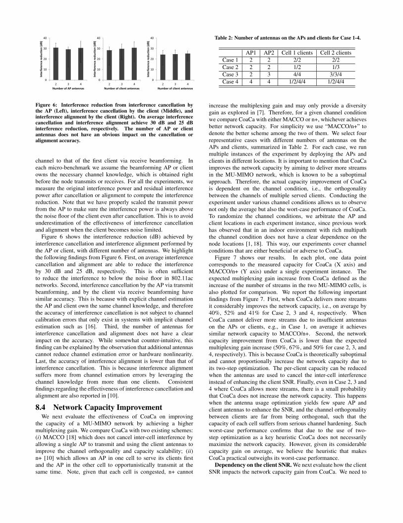
Figure 6: Interference reduction from interference cancellation bythe AP (Left), interference cancellation by the client (Middle), andinterference alignment by the client (Right). On average interferencecancellation and interference alignment achieve 30 dB and 25 dBinterference reduction, respectively. The number of AP or clientantennas does not have an obvious impact on the cancellation oralignment accuracy.
channel to that of the first client via receive beamforming. Ineach micro-benchmark we assume the beamforming AP or clientowns the necessary channel knowledge, which is obtained rightbefore the node transmits or receives. For all the experiments, wemeasure the original interference power and residual interferencepower after cancellation or alignment to compute the interferencereduction. Note that we have properly scaled the transmit powerfrom the AP to make sure the interference power is always abovethe noise floor of the client even after cancellation. This is to avoidunderestimation of the effectiveness of interference cancellationand alignment when the client becomes noise limited.
Figure 6 shows the interference reduction (dB) achieved byinterference cancellation and interference alignment performed bythe AP or client, with different number of antennas. We highlightthe following findings from Figure 6. First, on average interferencecancellation and alignment are able to reduce the interferenceby 30 dB and 25 dB, respectively. This is often sufficientto reduce the interference to below the noise floor in 802.11acnetworks. Second, interference cancellation by the AP via transmitbeamforming, and by the client via receive beamforming havesimilar accuracy. This is because with explicit channel estimationthe AP and client own the same channel knowledge, and thereforethe accuracy of interference cancellation is not subject to channelcalibration errors that only exist in systems with implicit channelestimation such as [16]. Third, the number of antennas forinterference cancellation and alignment does not have a clearimpact on the accuracy. While somewhat counter-intuitive, thisfinding can be explained by the observation that additional antennascannot reduce channel estimation error or hardware nonlinearity.Last, the accuracy of interference alignment is lower than that ofinterference cancellation. This is because interference alignmentsuffers more from channel estimation errors by leveraging thechannel knowledge from more than one clients. Consistentfindings regarding the effectiveness of interference cancellation andalignment are also reported in [10].
8.4 Network Capacity ImprovementWe next evaluate the effectiveness of CoaCa on improving
the capacity of a MU-MIMO network by achieving a highermultiplexing gain. We compare CoaCa with two existing schemes:(i) MACCO [18] which does not cancel inter-cell interference byallowing a single AP to transmit and using the client antennas toimprove the channel orthogonality and capacity scalability; (ii)n+ [10] which allows an AP in one cell to serve its clients firstand the AP in the other cell to opportunistically transmit at thesame time. Note, given that each cell is congested, n+ cannot
Table 2: Number of antennas on the APs and clients for Case 1-4.
AP1 AP2 Cell 1 clients Cell 2 clientsCase 1 2 2 2/2 2/2Case 2 2 2 1/2 1/3Case 3 2 3 4/4 3/3/4Case 4 4 4 1/2/4/4 1/2/4/4
increase the multiplexing gain and may only provide a diversitygain as explored in [7]. Therefore, for a given channel conditionwe compare CoaCa with either MACCO or n+, whichever achievesbetter network capacity. For simplicity we use “MACCO/n+” todenote the better scheme among the two of them. We select fourrepresentative cases with different numbers of antennas on theAPs and clients, summarized in Table 2. For each case, we runmultiple instances of the experiment by deploying the APs andclients in different locations. It is important to mention that CoaCaimproves the network capacity by aiming to deliver more streamsin the MU-MIMO network, which is known to be a suboptimalapproach. Therefore, the actual capacity improvement of CoaCais dependent on the channel condition, i.e., the orthogonalitybetween the channels of multiple served clients. Conducting theexperiment under various channel conditions allows us to observenot only the average but also the wort-case performance of CoaCa.To randomize the channel conditions, we arbitrate the AP andclient locations in each experiment instance, since previous workhas observed that in an indoor environment with rich multipaththe channel condition does not have a clear dependence on thenode locations [1, 18]. This way, our experiments cover channelconditions that are either beneficial or adverse to CoaCa.
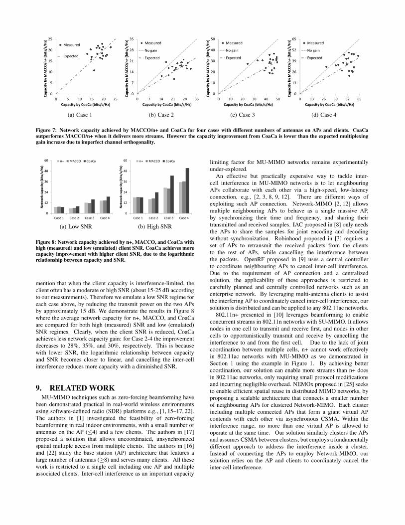
Figure 7 shows our results. In each plot, one data pointcorresponds to the measured capacity for CoaCa (X axis) andMACCO/n+ (Y axis) under a single experiment instance. Theexpected multiplexing gain increase from CoaCa defined as theincrease of the number of streams in the two MU-MIMO cells, isalso plotted for comparison. We report the following importantfindings from Figure 7. First, when CoaCa delivers more streamsit considerably improves the network capacity, i.e., on average by40%, 52% and 41% for Case 2, 3 and 4, respectively. WhenCoaCa cannot deliver more streams due to insufficient antennason the APs or clients, e.g., in Case 1, on average it achievessimilar network capacity to MACCO/n+. Second, the networkcapacity improvement from CoaCa is lower than the expectedmultiplexing gain increase (50%, 67%, and 50% for case 2, 3, and4, respectively). This is because CoaCa is theoretically suboptimaland cannot proportionally increase the network capacity due toits two-step optimization. The per-client capacity can be reducedwhen the antennas are used to cancel the inter-cell interferenceinstead of enhancing the client SNR. Finally, even in Case 2, 3 and4 where CoaCa allows more streams, there is a small probabilitythat CoaCa does not increase the network capacity. This happenswhen the antenna usage optimization yields few spare AP andclient antennas to enhance the SNR, and the channel orthogonalitybetween clients are far from being orthogonal, such that thecapacity of each cell suffers from serious channel hardening. Suchworst-case performance confirms that due to the use of two-step optimization as a key heuristic CoaCa does not necessarilymaximize the network capacity. However, given its considerablecapacity gain on average, we believe the heuristic that makesCoaCa practical outweighs its worst-case performance.
Dependency on the client SNR. We next evaluate how the clientSNR impacts the network capacity gain from CoaCa. We need to
0
5
10
15
20
25
0 5 10 15 20 25
Ca
pa
city
by
MA
CC
O/n
+ (
bit
s/s/
Hz)
Capacity by CoaCa (bits/s/Hz)
Measured
Expected
(a) Case 1
0
7
14
21
28
35
0 7 14 21 28 35
Ca
pa
city
by
MA
CC
O/n
+ (
bit
s/s/
Hz)
Capacity by CoaCa (bits/s/Hz)
Measured
No gain
Expected
(b) Case 2
0
10
20
30
40
50
0 10 20 30 40 50
Ca
pa
city
by
MA
CC
O/n
+ (
bit
s/s/
Hz)
Capacity by CoaCa (bits/s/Hz)
Measured
No gain
Expected
(c) Case 3
0
13
26
39
52
65
0 13 26 39 52 65
Ca
pa
city
by
MA
CC
O/n
+ (
bit
s/s/
Hz)
Capacity by CoaCa (bits/s/Hz)
Measured
No gain
Expected
(d) Case 4
Figure 7: Network capacity achieved by MACCO/n+ and CoaCa for four cases with different numbers of antennas on APs and clients. CoaCaoutperforms MACCO/n+ when it delivers more streams. However the capacity improvement from CoaCa is lower than the expected multiplexinggain increase due to imperfect channel orthogonality.
0
12
24
36
48
60
Case 1 Case 2 Case 3 Case 4
Ne
two
rk c
ap
aci
ty (
bit
s/s/
Hz)
n+ MACCO CoaCa
(a) Low SNR
0
12
24
36
48
60
Case 1 Case 2 Case 3 Case 4
Ne
two
rk c
ap
aci
ty (
bit
s/s/
Hz)
n+ MACCO CoaCa
(b) High SNR
Figure 8: Network capacity achieved by n+, MACCO, and CoaCa withhigh (measured) and low (emulated) client SNR. CoaCa achieves morecapacity improvement with higher client SNR, due to the logarithmicrelationship between capacity and SNR.
mention that when the client capacity is interference-limited, theclient often has a moderate or high SNR (about 15-25 dB accordingto our measurements). Therefore we emulate a low SNR regime foreach case above, by reducing the transmit power on the two APsby approximately 15 dB. We demonstrate the results in Figure 8where the average network capacity for n+, MACCO, and CoaCaare compared for both high (measured) SNR and low (emulated)SNR regimes. Clearly, when the client SNR is reduced, CoaCaachieves less network capacity gain: for Case 2-4 the improvementdecreases to 28%, 35%, and 30%, respectively. This is becausewith lower SNR, the logarithmic relationship between capacityand SNR becomes closer to linear, and cancelling the inter-cellinterference reduces more capacity with a diminished SNR.
9. RELATED WORKMU-MIMO techniques such as zero-forcing beamforming have
been demonstrated practical in real-world wireless environmentsusing software-defined radio (SDR) platforms e.g., [1, 15–17, 22].The authors in [1] investigated the feasibility of zero-forcingbeamforming in real indoor environments, with a small number ofantennas on the AP (≤4) and a few clients. The authors in [17]proposed a solution that allows uncoordinated, unsynchronizedspatial multiple access from multiple clients. The authors in [16]and [22] study the base station (AP) architecture that features alarge number of antennas (≥8) and serves many clients. All thesework is restricted to a single cell including one AP and multipleassociated clients. Inter-cell interference as an important capacity
limiting factor for MU-MIMO networks remains experimentallyunder-explored.
An effective but practically expensive way to tackle inter-cell interference in MU-MIMO networks is to let neighbouringAPs collaborate with each other via a high-speed, low-latencyconnection, e.g., [2, 3, 8, 9, 12]. There are different ways ofexploiting such AP connection. Network-MIMO [2, 12] allowsmultiple neighbouring APs to behave as a single massive AP,by synchronizing their time and frequency, and sharing theirtransmitted and received samples. IAC proposed in [8] only needsthe APs to share the samples for joint encoding and decodingwithout synchronization. Robinhood proposed in [3] requires aset of APs to retransmit the received packets from the clientsto the rest of APs, while cancelling the interference betweenthe packets. OpenRF proposed in [9] uses a central controllerto coordinate neighbouring APs to cancel inter-cell interference.Due to the requirement of AP connection and a centralizedsolution, the applicability of these approaches is restricted tocarefully planned and centrally controlled networks such as anenterprise network. By leveraging multi-antenna clients to assistthe interfering AP to coordinately cancel inter-cell interference, oursolution is distributed and can be applied to any 802.11ac networks.
802.11n+ presented in [10] leverages beamforming to enableconcurrent streams in 802.11n networks with SU-MIMO. It allowsnodes in one cell to transmit and receive first, and nodes in othercells to opportunistically transmit and receive by cancelling theinterference to and from the first cell. Due to the lack of jointcoordination between multiple cells, n+ cannot work effectivelyin 802.11ac networks with MU-MIMO as we demonstrated inSection 1 using the example in Figure 1. By achieving bettercoordination, our solution can enable more streams than n+ doesin 802.11ac networks, only requiring small protocol modificationsand incurring negligible overhead. NEMOx proposed in [25] seeksto enable efficient spatial reuse in distributed MIMO networks, byproposing a scalable architecture that connects a smaller numberof neighbouring APs for clustered Network-MIMO. Each clusterincluding multiple connected APs that form a giant virtual APcontends with each other via asynchronous CSMA. Within theinterference range, no more than one virtual AP is allowed tooperate at the same time. Our solution similarly clusters the APsand assumes CSMA between clusters, but employs a fundamentallydifferent approach to address the interference inside a cluster.Instead of connecting the APs to employ Network-MIMO, oursolution relies on the AP and clients to coordinately cancel theinter-cell interference.

In this work, we exploit the multiple antennas on clients tocombat the inter-cell interference in multiple MU-MIMO cells andto achieve a higher multiplexing gain. Alternatively, MACCOproposed in [18] seeks to use the client antennas to improve thechannel orthogonality between the clients, in order to make thecapacity of a single MU-MIMO cell better scale with the numberof clients. Our work and [18] actually represent two different waysof leveraging the client antennas to achieve either a SNR gainor a multiplexing gain, and therefore need to address completelydifferent technical challenges. More importantly, the applicabilityof [18] is restricted to a single cell or multiple cells where inter-cellinterference is insignificant; in this work we focus on situationswhere inter-cell interference stands as the bottleneck of the MU-MIMO network capacity and proposes a solution to overcome it.
10. CONCLUSIONIn this work, we tackle the inter-cell interference problem
in 802.11ac-based MU-MIMO networks by seeking to enablecoordinated interference cancellation in a practical way. Toachieve this, we propose a solution consisting of two separateoptimizations: antenna usage optimization and beamformingweight optimization. With the separation, both optimizations canbe integrated into 802.11ac with small modifications and negligibleoverhead. The experimental evaluation of our protocol, CoaCa,demonstrates its effectiveness to eliminate inter-cell interferenceand improve the network capacity in realistic indoor wirelessenvironments.
ACKNOWLEDGEMENTSThis work was funded in part by NSF grants MRI 0923479,NetSE 101283, MRI 1126478, CNS 1218700 and CNS 1314822.The authors would like to thank Ashutosh Sabharwal for manyinsightful suggestions. The authors also thank the anonymousreviewers and the paper shepherd for their constructive commentsthat have considerably improved the paper.
11. REFERENCES[1] E. Aryafar, N. Anand, T. Salonidis, and E. W. Knightly.
Design and Experimental Evaluation of Multi-UserBeamforming in Wireless LANs. In Proc. ACM Int. Conf.Mobile Computing and Networking (MobiCom), 2010.
[2] H. V. Balan, R. Rogalin, A. Michaloliakos, and K. Psounis.Achieving High Data Rates in a Distributed MIMO System.In Proc. ACM Int. Conf. Mobile Computing and Networking(MobiCom), 2012.
[3] T. Bansal, B. Chen, K. Srinivasan, and P. Sinha. RobinHood:Sharing the Happiness in a Wireless Jungle. In Proc. ACMInt. Workshop Mobile Computing Systems and Applications(HotMobile), 2014.
[4] O. Bejarano, E. W. Knightly, and M. Park. IEEE 802.11ac:From Channelization to Multi-User MIMO. IEEECommunication Magazine, 2013.
[5] O. Bejarano, E. Magistretti, O. Gurewitz, and E. W.Knightly. MUTE: Sounding Inhibition for MU-MIMOWLANs. In Proc. IEEE Int. Conf. Sensing, Communicationand Networking (SECON), 2014.
[6] V. R. Cadambe and S. A. Jafar. Interference Alignment andDegrees of Freedom of the K-User Interference Channel.IEEE Trans. on Information Theory, 2008.
[7] B. Chen, K. C. Lin, and H. Wei. Harnessing ReceiveDiversity in Distributed Multi-User MIMO Networks. InProc. ACM SIGCOMM (Poster), 2013.
[8] S. Gollakota, S. D. Perli, and D. Katabi. InterferenceAlignment and Cancellation. In Proc. ACM SIGCOMM,2009.
[9] S. Kumar, D. Cifuentes, S. Gollakota, and D. Katabi.Bringing Cross-Layer MIMO to TodayâAZs Wireless LANs.In Proc. ACM SIGCOMM, 2013.
[10] K. C. Lin, S. Gollakota, and D. Katabi. Random AccessHeterogeneous MIMO networks. In Proc. ACM SIGCOMM,2011.
[11] M. A. Maddah-Ali, A. S. Motahari, and A. K. Khandani.Communication Over MIMO X Channels: InterferenceAlignment, Decomposition, and Performance Analysis.IEEE Trans. on Information Theory, 2008.
[12] H. Rahul, S. Kumar, and D. Katabi. JMB: Scaling WirelessCapacity with User Demands. In Proc. ACM SIGCOMM,2012.
[13] Rice University. WARPLab.http://warp.rice.edu/trac/wiki/WARPLab.
[14] Rice University. Wireless Open Access Research Platform(WARP). http://warp.rice.edu/trac.
[15] W. Shen, Y. Tung, K. Lee, K. C. Lin, S. Gollakota,D. Katabi, and M. Chen. Rate Adaptation for 802.11Multiuser MIMO Networks. In Proc. ACM Int. Conf. MobileComputing and Networking (MobiCom), 2012.
[16] C. Shepard, H. Yu, N. Anand, E. Li, T. Marzetta, R. Yang,and L. Zhong. Argos: Practical Many-antenna Base Stations.In Proc. ACM Int. Conf. Mobile Computing and Networking(MobiCom), 2012.
[17] K. Tan, H. Liu, J. Fang, W. Wang, J. Zhang, M. Chen, andG. M. Voelker. SAM: Enabling Practical Spatial MultipleAccess in Wireless LAN. In Proc. ACM Int. Conf. MobileComputing and Networking (MobiCom), 2009.
[18] Withheld for blind review. Achieving Better ChannelOrthogonality for Improved User Scaling of Multi-userMIMO. In submission to MobiCom (submission ID: 107),2014.
[19] S. Venkatesan, A. Lozano, and R. Valenzuela. NetworkMIMO: Overcoming Intercell Interference in IndoorWireless Systems. In Proc. IEEE Asilomar Conf. on Signals,Systems and Computers (ACSSC), 2007.
[20] X. Xie and X. Zhang. Scalable User Selection forMU-MIMO Networks. In Proc. IEEE Conf. ComputerCommunications (INFOCOM), 2014.
[21] X. Xie, X. Zhang, and K. Sundaresan. Adaptive FeedbackCompression for MIMO Networks. In Proc. ACM Int. Conf.Mobile Computing and Networking (MobiCom), 2013.
[22] Q. Yang, X. Li, H. Yao, J. Fang, K. Tan, W. Hu, J. Zhang,and Y. Zhang. BigStation: Enabling Scalable Real-timeSignal Processing in Large MU-MIMO Systems. In Proc.ACM SIGCOMM, 2013.
[23] H. Yu, L. Zhong, A. Sabharwal, and D. Kao. Beamformingon Mobile Devices: A First Study. In Proc. ACM Int. Conf.Mobile Computing and Networking (MobiCom), 2011.
[24] Z. Zeng, Y. Gao, K. Tan, and P. R. Kumar. CHAIN:Introducing Minimum Controlled Coordination into RandomAccess MAC. In Proc. IEEE Conf. ComputerCommunications (INFOCOM), 2011.
[25] X. Zhang, K. Sundaresan, M. A. Khojastepour,S. Rangarajan, and K. G. Shin. NEMOx: Scalable NetworkMIMO for Wireless Networks. In Proc. ACM Int. Conf.Mobile Computing and Networking (MobiCom), 2013.


![Radar Communication for Combating Mutual Interference of ... · frequency division multiplexing (OFDM) for radar commu-nications [9]–[11]. OFDM is widely used for communication](https://img.dokumen.tips/doc/110x75/5f42b1d6aa51657a3e22026c/radar-communication-for-combating-mutual-interference-of-frequency-division.jpg)