Embed Size (px)
Citation preview

1
ME 430ME 430 Lecture
Collection of Solar Energy (Solar Collectors)
Slides prepared by C. Cruickshankand S. Harrison
Components of Solar Thermal Systems
Standard solar water heating system with heating boiler for additional heating (S = temperature sensor)
How does a solar thermal system work?
From “Planning and Installing Solar Thermal Systems”, James & James/Earthscan, London, UK

2
Typical Indirect North American Solar Domestic Hot Water System
SolarCollector
FixedFlow Rate
Roof Line
HeatExchanger
VariableFlowRate
StorageTank
Cold MainsInlet
Electric Pump
Hot Waterto Load
StorageTank
Positioning of Collectors Rule of ThumbFor a year-round solar system in Canada, the best performance is from collectors facing due south, tilted at an angle equal to the latitude of the location and never shaded.
For a summer-only system, such as pool-heating, the tilt angle will be at a shallow angle.
If most of the use is in the winter, the panels will be at a steeper angle to capture the sunlight at lower sun altitude angles.
Summer Biased: Latitude – 15o
Winter Biased: Latitude + 15o

3
Solar Collector Designs
Different collector designs
The task of a solar collector is to achieve the highest possible thermal yield.
From “Planning and Installing Solar Thermal Systems”, James & James/Earthscan, London, UK
Solar Collector Designs
Concentration of solar radiation
Concentration of solar radiation: single reflector with two-axis tracking
Concentration of solar radiation: multiple reflectors with two-axis tracking
From “Planning and Installing Solar Thermal Systems”, James & James/Earthscan, London, UK

4
Geometry of Solar Collectors
Cross-section of a flat-plate collector
The gross surface area (collector area) is the product of the outside dimensions, and defines for example the minimum amount of roof area that is required for mounting.
The aperture area corresponds to the light entry area of the collector – that is the area through with the solar radiation passes to the collector itself.
The absorber area (also called the effective collector area) corresponds to the area of the actual absorber panel.
From “Planning and Installing Solar Thermal Systems”, James & James/Earthscan, London, UK
Reference Area
When comparing collectors, the reference area is important – that is, the surface area from which the collector’s characteristics values are drawn. For North American ratings, the reference area is equal to the gross area.
For the energy yield, it is not the collector (gross) area that is crucial but the absorber area. The exception to this is evacuated tube collectors with reflectors.

5
Geometry of Solar Collectors
Cross-section of a heat-pipe evacuated tube collector with description of the different surface areas
From “Planning and Installing Solar Thermal Systems”, James & James/Earthscan, London, UK
Geometry of Solar Collectors
Cross-section of a double evacuated tube collector (“Sydney tubes”) with description of the different surface areas
From “Planning and Installing Solar Thermal Systems”, James & James/Earthscan, London, UK

6
Unglazed CollectorsUnglazed collectors
• no glazing or insulated collector box
• consists only of an absorber (usually made of plastic)
• high thermal losses, used only at low operating temperatures
• typically used for swimming pools
• inexpensive
From “Planning and Installing Solar Thermal Systems”, James & James/Earthscan, London, UK
Glazed Flat-Plate Collectors
Section through a glazed flat-plate collector
1. Frame2. Seal3. Transparent cover4. Frame – side-wall
profile5. Thermal insulation6. Full-surface
absorber7. Fluid channel8. Fixing slot9. Rear wall
Design of glazed flat-plate collectors
From “Planning and Installing Solar Thermal Systems”, James & James/Earthscan, London, UK

7
Glazed Flat-Plate CollectorsThe absorber consists of a heat conducting metal sheet (made of copper or aluminium, as a single surface or in strips) with a dark coating. The tubes for the heat transfer medium, which are usually made of copper, are connected conductively to the absorber.
Source: http://www.sunraysolar.com/Source: http://www.daviddarling.info
Absorber fin attached to copper tube by arc welding
Absorber wrapped around copper tube
SunstripHigh performance absorber fin constructed of aluminium with a copper “water way” to prevent corrosion.
Geometry is optimized to use minimum material.
Laser WeldingAluminium absorber fin attached to copper tube by laser welding.

8
Absorber FinsTemperature Profile
Arrangement of Absorbers
From “Solar Thermal Systems”, James & James, London, UK
Collector with harp absorber
Rear side of an absorber made of aluminium with enclosed, sunk-in stainless steel meander tubes
9
Radiation Terms
degree of transmission
degree of absorption(absorption coefficient)
degree of reflection
τ transmitted radiation = incident radiation
ρ reflected radiation = incident radiation
α absorbed radiation = incident radiation
The variables are dependent on the material and wavelength. The sum of and is equal to 1 (100%).ρ α τ,
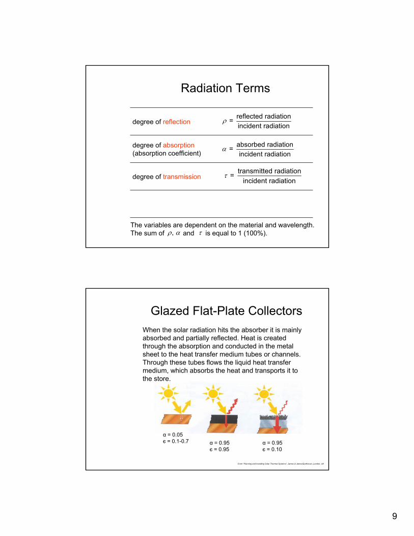
Glazed Flat-Plate CollectorsWhen the solar radiation hits the absorber it is mainly absorbed and partially reflected. Heat is created through the absorption and conducted in the metal sheet to the heat transfer medium tubes or channels. Through these tubes flows the liquid heat transfer medium, which absorbs the heat and transports it to the store.
α = 0.95є = 0.95
α = 0.95є = 0.10
α = 0.05є = 0.1-0.7
From “Planning and Installing Solar Thermal Systems”, James & James/Earthscan, London, UK

10
Glazed Flat-Plate CollectorsMost spectral-selective layers have an absorption rate of 90-95%, and an emission rate of 5-15%. Commonly used selective coatings consist of black chrome or black nickel.
From “Planning and Installing Solar Thermal Systems”, James & James/Earthscan, London, UK
The optical losses are dependent on the transparency of the glass cover (transmission) and the absorption capacity of the absorber surface (absorption) and are described by the optical efficiency:
The thermal losses are dependent on the temperature difference between the absorber and the outside air, on the insolation, and on the construction of the collector. The influence of the construction is described by the heat loss coefficient , k (or k-value) measured in W/m2K.
Solar Collector Efficiency
Optical and thermal losses
From “Planning and Installing Solar Thermal Systems”, James & James/Earthscan, London, UK
Optical losses
Thermal losses
Usable thermal energyη τα=

11
Glazed Flat-Plate Collector Advantages
• offers multiple mounting options
• good price/performance ratio
• cheaper than vacuum collector
Disadvantages
• lower efficiency than vacuum collectors for high temperature applications, because the heat loss coefficient is higher
• not suitable for generating high temperatures (+100oC)
• requires more roof space than vacuum collectors do
• support system is necessary for flat roof mounting
Vacuum Collectors Evacuated tube collectors
In order to suppress thermal losses through convection, the volume enclosed in the glass tubes must be evacuated to less than 10-2 bar. Additional evacuation prevents losses through thermal conduction. The radiation losses cannot be reduced by creating a vacuum. The losses are kept low by selective coatings(small ε value).
From “Planning and Installing Solar Thermal Systems”, James & James/Earthscan, London, UK

12
Vacuum CollectorsEvacuated tube collectorsThe absorber is installed as either flat (A) or upwards vaulted (B) metal strips or as a coating applied to an internal glass bulb in an evacuated glass tube.
A B
The tubes are linked at the top by an insulated distributor or collector box, in which the feed or return lines run.
At the base, the tubes are fitted to a rail with tube holders.
Vacuum CollectorsConcentrating systems providing process heat
Schematic structure of a compound parabolic concentrator (CPC) tube collector
From “Planning and Installing Solar Thermal Systems”, James & James/Earthscan, London, UK
Cross-section through a “Sydney” tube with round absorber

13
Vacuum Collectors Advantages
• achieves a high efficiency even with large ΔT’s between absorber and surroundings
• supports space heating applications more effectively than do glazed flat-plate collectors
• low in weight, can be assembled at installation site
Disadvantages
• more expensive than a glazed flat-plate collector
• cannot be used for in-roof installation
• heat pipe systems need to be inclined at least 25O
Efficiencies of Collectors
Efficiency characteristics curves for different types of collector and their areas of applications (at irradiation of 1000 W/m2K)
Collector characteristics curves and applications
From “Planning and Installing Solar Thermal Systems”, James & James/Earthscan, London, UK

14
Economics
40 – 50Unglazed
150 – 200Glazed flat plate(with a selective surface)
500 – 1000Vacuum tube
Price ( $ / m2 )Type of Collector