Embed Size (px)
Citation preview
IS : 3043 - 1987 (Reaffirmed 2001 )
Indian Standard
CODE OF PRACTICE FOR EARTHING (First Revision)
Second Repriat FEBRUARY1998
UDC 621316.99:006.76
© Copyright 1988
B U R E A U O F I N D I A N S T A N D A R D S MANAK BHAVAN, 9 BAHADUR SHAH ZAFAR MARG
NEW DELHI 110002
Price Rs 225.00 September 1988
IS 13043-1987
Indian Standard CODE OF PRACTICE FOR EARTHING
(First Revision) Electrical Installations Sectional Committee, ETDG 20
Chmrmmn SHBI M. L. DONQKE
M-3 Satyam, 88 Sion Circle, Bombay 400022 Representing
Engineer-in-Chief's Branch, Army Headquarters ( Ministry of Defence ) , New Delhi
Members SHBI P. AMANTHABAMAN
SHBI S. K. SHANOABI ( Alternate) SHBI P. D. BAOADE
SHBI R. K. K A U L ( Alternate) SHBI V. S. BHATIA
SHBI M. M. SHKTHMA ( Alternate) SHBI K. V. CHAUBAL
SHBI K. S. JOSHI ( Altirnatt) SHBI R. R. CHOCDHUBI
SHBI N. BALASUBRAMANIAN ( Alternate ) CHIEF ELECTRICAL ENGINEER
DEPUTY DIBECTOB STANDARDS ( ELEO )-DI, RDSO ( Alternate )
CHIEF ELECTRICAL IMSFKOTOB TO GOVEBN«BNT OF TAMIL NADTJ
ELECTBICAL INSPECTOR ( TECHNICAL ) TO GOVERNMENT OF TAMIL N A D U ( Alternate)
CHIEF ENGINEER ( ELEC )-I SUPERINTENDENT SUBVKYOB or WORKS
( ELEC )-I ( Alternate ) SHBI DEVENDKB N A T H
SHBI T . P. R. SABMA ( Alternate ) SHBI K. W. DHABMADHIKABI
D B V. N. MALLBB ( Alternate ) SHBI G. L. D C A
SHBI S. K. SETHI ( Alternate ) SHBI R. G KHANNA
SHBI P. S. SAWHKKY (Alternate ) MEMBEB ( HYDRO-ELECTBIC )
DIBECTOB ( HED )-I ( Alternate) ER S. PANEERSELVAM
SHBI V. JANABDEANAH (Alternate ) SHRI K. P. R. PILLAI
SHBI C. R. R. MENON ( Alternate ) SHBI V. R A D B A KRISHNAN SHBI H. S. R A O PBOF G. RAVEENDRAN N A I B SHBI S. R. SARDA SHBI R. SATHIYABAL
SHBI K. K. MONDAL ( Alternate ) SHBI H. K. SITABAM
SHBI S. K. PALIT ( Alternate ) SHBI P. SBINIVASA POTI
SHBI JOSEPH PHILOMBNY ( Alternate ) SHBI D, S. T A W A B I
SHBI S. J. HABIDAS ( Alternate ) SHBI G. N. THADANI
SHBI S. K, GHOSH (Alternate ) SHBI G. S. T H A K U B SHBI V. T. WABANG
S H B I R. P. PATKL ( Alternate ) SHBI S. P. SACHDEV,
Director ( Elec tech )
Tata Consulting Engineers, Bombay
Siemens India Ltd, Bombay
Federation of Electricity Undertaking of India, Bombay
Larsen & Toubro ( Construction Group ) , Madras
Railway Board ( Ministry of Railways ) , New Delhi
Chief Electrical Inspector to Government of Tamil Nadu, Madras
Central Public Works Department, New Delhi
Larsen & Toubro Ltd, Bombay
Jyoti Ltd, Vadodara
Rural Electrification Corporation Ltd, New Delhi
Delhi Electric Supply Undertaking, New Delhi
Central Electricity Authority, New Delhi
Tamil Nadu Electricity Board, Madras
Fact Engineering and Design Organization, Udhyogamandal
Bharat Heavy Electricals Ltd, Hyderabad Crompton Greaves Ltd, Bombay Chief Electrical Inspector to the Government of Kerala, Trivandrum. Maharashtra State Electricity Board, Bombay Tariff Advisory Committee ( General Insurance ) , Bombay
Calcutta Electric Supply Corporation Ltd, Calcutta
Karnataka Electricity Board, Bangalore
Electrical Engineer to Government of Maharashtra, Bombay
Engineers India Ltd, New Delhi
Chief Electrical Inspector, Government of Madhya Pradesh, Bhopal Bombay Electric Supply and Transport Undertaking, Bombay
Director General, BIS ( Ex-qfficio Member )
Secretary SHBI K. GANESH
Deputy Director ( Elec tech ) , BIS ( Continued on page 2 )
© Copyright 1988 BUREAU OF INDIAN STANDARDS
This publication is protected under the Indian Copyright Act ( XIV 1957 ) and production in whole or in part by any means except with written permission of the publisher shall be deemed to be an infringment of copyright under thesaid Act.
IS > 3643 ■ 1987
( Continued from page I )
Panel for the Revision of IS : 3043, ETDC 20 : P38
Convener S U B i N. BALASOBBAMANIAN
Members PBOF G. RAVEENDBAN N A I R SHBI V. SATHTANATHAN S H B I G. S. THAKTJB S H B I R. SATHIYABAL S H B I K. P. R. PILLAI
Representing Larsen & Toubro ( Construction Group ) , Madras
Chief Electrical Inspector to the Government of Kerala, Trivandrum Tamil Nadu Electricity Board, Madras Chief Electrical Inspector, Government of Madhya Pradesh, Bhopai Tariff Advisory Committee, Madras Fact Engineering and Design Organization, Udyogamandal
2
I S J
CONTENTS Page
0 . FOREWORD . . . 5
1. SCOPE . . . 6
SECTION 1 GENERAL GUIDELINES 2. TERMINOLOGY . . . ?
3. EXCHANGE OF INFORMATION . . . 8
4. STATUTORY PROVISIONS FOR EARTHING . . . 9
5. FACTORS INFLUENCING THE CHOICE OF EARTHED AND UNEARTHED SYSTEMS . . . 10
6. SYSTEM EARTHING . . . 11
7. EQUIPMENT EARTHING . . . 15
SECTION 2 CONNECTIONS TO EARTH
8. RESISTANCE TO EARTH . . . 16
9. EARTH ELECTRODE . . . 19
10. CURRENT DENSITY AT THE SURFACE OF AN EARTH ELECTRODE . . . 27
11. VOLTAGE GRADIENT AROUND EARTH ELECTRODES . . . 27
12. CONNECTIONS TO EARTH ELECTRODES — EARTHING AND PROTECTIVE CONDUCTORS . . . 27
13. EARTHING ARRANGEMENT FOR PROTECTIVE PURPOSES . . . 32
14. EARTHING ARRANGEMENT FOR FUNCTIONAL PURPOSES . . . 32
15. EARTHING ARRANGEMENTS FOR COMBINED PROTECTIVE AND FUNCTIONAL PURPOSES . . . 32
16. EQUIPOTENTIAL BONDING CONDUCTORS . . 33
17. TYPICAL SCHEMATIC OF EARTHING AND PROTECTIVE CONDUCTORS . . . 33
SECTION 3 EARTH FAULT PROTECTION ON CONSUMER'S PREMISES
18. EARTH FAULT PROTECTION IN INSTALLATIONS . . . 34
19. SELECTION OF DEVICES FOR AUTOMATIC DISCONNECTION OF SUPPLY . . . 39
SECTION 4 POWER STATIONS, SUBSTATIONS AND OVERHEAD LINES
20. EARTHING IN POWER STATIONS AND SUBSTATIONS . . . 43
21. EARTHING ASSOCIATED*WITH OVERHEAD POWER LINES . . . 52
SECTION 5 INDUSTRIAL PREMISES
22. GUIDELINES FOR EARTHING IN INDUSTRIAL PREMISES . . . 53
SECTION 6 STANDBY AND OTHER PRIVATE GENERATING PLANTS
23. EARTHING IN STANDBY AND O T H E R PRIVATE GENERATING PLANTS ( INCLUDING PORTABLE AND MOBILE GENERATORS ) . . . 56
3
IS t 3049 - 19f7
Page SLCTION 7 MEDICAL ESTABLISHMENT
24. PROTECTIVE MEASURES THROUGH EARTHING IN MEDICAL ESTABLISHMENT . . . 64
25. SUPPLY CHARACTERISTICS AND PARAMETERS . . . 65
SECTION 8 STATIC AND LIGHTNING PROTECTION EARTHING
( Under consideration. Clauses 26 and 27 reserved for Section 8 )
SECTION 9 MISCELLANEOUS INSTALLATIONS AND CONSIDERATIONS
28. 29. 30. 31. 32.
33. 34.
EARTHING IN POTENTIALLY HAZARDOUS AREAS TELECOMMUNICATION CIRCUITS AND APPARATUS BUILDING SITES MINES AND QUARRIES STREET LIGHTING AND OTHER ELECTRICALLY FURNITURE EARTHING OF CONDUCTORS FOR SAFE WORKING MAINTENANCE OF EARTH ELECTRODES
SUPPLIES STREET
69 70 71 71
73 74 76
SECTION 10 MEASUREMENTS AND CALCULATIONS
35. CALCULATION OF EARTH FAULT CURRENTS . . . 76 36. MEASUREMENT OF EARTH RESISTIVITY . . . 77 37. MEASUREMENT OF EARTH ELECTRODE RESISTANCE . . . 79 38. MEASUREMENT OF EARTH LOOP IMPEDANCE . . . 80
SECTION 11 DATA PROCESSING INSTALLATIONS
39. EARTHING REQUIREMENTS FOR INSTALLATIONS OF DATA PROCESSING EQUIPMENT #> 80
40. EXAMPLE OF USE OF TRANSFORMERS . . . 83
4
IS i 3043 • 1987
Indian Standard CODE OF PRACTICE FOR EARTHING
(First Revision)
0. FOREWORD
0.1 This Indian Standard ( First Revision ) was adopted by the Bureau of Indian Standards on € August 1987, after the draft finalized by the Electrical Installations Sectional Committee, had been approved by the Electrotechnical Division Council.
0.2 The Indian Electricity Rules, together with the supplementary regulations of the State Electricity Departments and Electricity Undertakings, govern the electrical installation work in generating stations, substations, industrial locations, buildings, etc, in the country. To ensure safety of life and apparatus against earth faults, it was felt necessary to prepare a code of practice for earthing. This code of practice is intended to serve as a consolidated guide to all those who are concerned with the design, installation, inspection and maintenance of electrical systems and apparatus.
0.3 The subject of earthing covers the problems relating to conduction of electricity through earth. The terms earth and earthing have been used in this code irrespective of reliance being placed on the earth itself as a low impedance return path of the fault current. As a matter of fact, the earth now rarely serves as a part of the return circuit but is being used mainly for fixing the voltage of system neutrals. The earth connection improves seivice continuity and avoids damage to equipment and danger to human life.
0.4 The object or an earthing system is to provide as nearly as possible a surface under and around a station which shall be at a uniform potential and as nearly zero or absolute earth potential as possible. The purpose of this is to ensure that, in general, all parts of apparatus other than live parts, shall be at earth potential, as well as to ensure that operators and attendants shall be at earth potential at all times. Also by providing such an earth surface of uniform potential under and surrounding the station, there can exist no difference of potential in a short distance big enough to shock or injure an attendant when short-circuits or other abnormal occurrences take place. The recommendations in this code are made in order that these objects may be carried out.
0.5 Earthing associated with current-carrying conductor is normally essential to the security of the system and is generally known as system earthing, while earthing of non-current carrying metal work and conductor is essential-to the safety of human life, animals and property, and is generally known as equipment earthing. 0.6 Since the publication of this standard in 1966, considerable experience has been gained through the implementation of its various stipulations. Moreover, several new concepts have been introduced the world over, on the understanding of functional and protective earthing with a view to take into account a variety of complex problems encountered in actual practice. In the context of increased use of electric power and the associated need for safety in the design of installations, it had become necessary to prepare an overall revision of the earlier version of the Code.
0.7 In this Code, the terms 'earthing' and 'grounding' are used synonymously. However, this Code introduces several new terms ( see 2.15, 2.17, 2.28, etc ) and distinguishes earthing 'conductor' from 'protective conductor'.
0.8 This Code includes comprehensive guidelines on choosing the proper size of the various components ot the earthing system, particularly earthing and protective conductors as well as earth electrodes. Guidance included on determination of relevant 'k' factor depending on ( see Sec 2 ) material properties and boundary conditions, and the associated minimum cross-sectional area would assist in a more scientific design of the earthing system under various circumstances.
0.9 For the first time, the Code also includes comprehensive guidelines on earth fault protection in consumers' premises to commensurate with the provisions of IE RuUs 1956. It includes specific guidelines on earthing system design to achieve the desired degree of shock hazard protection from earth leakages. The rules given in Section 3 of the Code should be read in conjunction with corresponding regulations given in the wiring code ( see IS : 732 ).
0.9.1 Protection against shock, both in normal service ( direct contact ) and in case of fault ( indirect contact) can be achieved by several
5
IS i 3043-1987
measures. Details of such protective measures and guidance on their choice is the subject matter of debate in the process of revision of IS : 732*. Earth fault/leakage protection sought to be achieved through equi potential bonding and automatic disconnection of supply is envisaged to prevent a touch voltage from persisting for such a duration that would be harmful to human beings. Guidance on achieving this protection is covered in Sec 3 of the Code.
0.9.2 While detailed guidelines are covered in specific portions of the Code, the following shall be noted:
a) For solidly grounded systems, it shall be sufficient to check whether the characteristics of protective device for automatic disconnection, earthing arrangements and relevant impedances of the circuits are properly coordinated to ensure that voltages appearing between simultaneously accessible, exposed and extraneous conductive parts are within the magnitudes that would not cause danger;
b) For systems where the earthing is deemed to be adequate, it shall be checked whether the main overcurrent protective device is capable of meeting the requirements in the wiring code; and
c) Where the main overcurrent protective device did not fulfil the requirements or where the earthing is considered inadequate, then a separate residual current device would be necessary to be installed, the earth fault loop impedance and the tripping characteristics so chosen that they comply with safe touch voltage limits.
0. |0 The revision of the Code aims at consolidating in one volume all the essential guidelines needed for preparing a good earthing design in an electrical installation. The revision also attempts to be more elaborate than the earlier version, especially in areas of specific interest keeping in view the need and wide experience gained the world over.
0*11 For convenience of identifying areas of interest by any specific users of the Code, the information contained in this standard is divided into different Sections as follows:
Section 1 General guidelines; Section 2 Connections to earth; Section 3 Earth-fault protection in con
sumer's premises; Section 4 Power stations, substations and
overhead lines; v
Section 5 Industrial premises; Section 6 Standby and other private gene
rating plant; Section 7 Medical establishments; Section 8 Static and lightning protection
grounding; Section 9 Miscellaneous installations and
considerations; Section 10 Measurements and calculations;
and Section 11 Data processing installations.
0.12 In the preparation of the Code, assistance has been taken from the following:
I EC Pub 364 ( and Parts ) Electrical installations in buildings. International Electro-technical Commission.
BS Document 84/21243 Draft standard code of practice on earthing ( revision of CP 1013: 1965 ). British Standards Institution.
ANSI/IEEE Std 142-1982 IEEE Recommended practice for grounding of industrial and commercial power systems. American National Standards Institute ( USA ).
0.13 For the purpose of deciding whether a particular requirement of this standard is complied with, the final value, observed or calculated, expressing the result of a test or analysis shall be rounded off in accordance witrTIS : 2-1960*. The number of significant places retained in the rounded off value should be the same as that of the specified value in this standard.
•Code of practice for electrical wiring installation. 'Rules for rounding off numerical values ( rnised }.
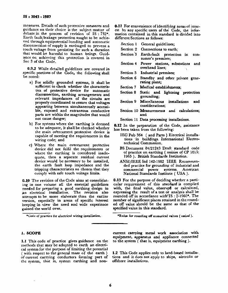
1. SCOPE
1.1 This code of practice gives guidance on the methods that may be adopted to earth an electrical system for the purpose of limiting the potential ( with respect to the general mass of the earth ) of current carrying conductors forming part of the system, that is, system earthing and non-
current carrying metal work association with, equipment, apparatus and appliance connected to the system ( that is, equipment earthing ).
1.2 This Code applies only to land-based installations and it does not apply to ships, aircrafis or offshore installations.
6
IS t 3043 - 1987
SECTION 1 GENERAL GUIDELINES
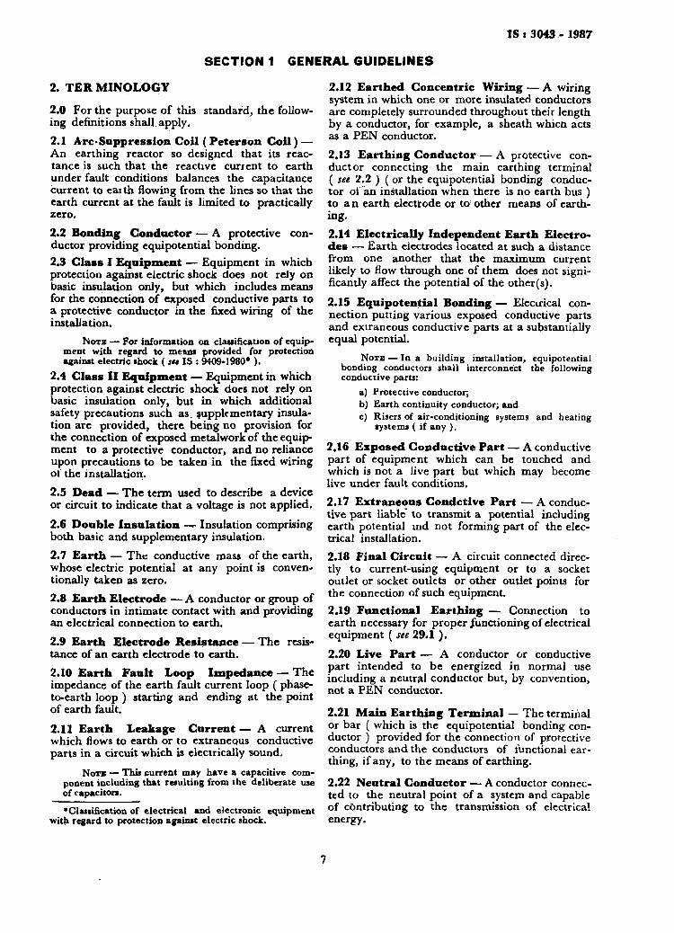
2. TER M1NOLOGY
2.0 For the purpose of this standard, the following definitions shall apply. 2.1 Arc-Suppression Coil ( Peterson Coil) — An earthing reactor so designed that its reactance is such that the reactive curient to earth under fault conditions balances the capacitance current to earth flowing from the lines so that the earth current at the fault is limited to practically zero. 2.2 Bonding Conductor — A protective conductor providing equipotential bonding. 2.3 Class I Equipment — Equipment in which protection against electric shock does not rely on basic insulation only, but which includes means for the connection of exposed conductive parts to a protective conductor in the fixed wiring of the installation.
Nor* — For information on classification of equipment with regard to means provided for protection against electric shock ( su IS : 9409-1980* ).
2.4 Class II Equipment — Equipment in which protection against electric shock does not rely on basic insulation only, but in which additional safety precautions such as. supplementary insulation are provided, there being no provision for the connection of exposed metalwork of the equipment to a protective conductor, and no reliance upon precautions to be taken in the fixed wiring of the installation. 2.5 Dead — The term used to describe a device or circuit to indicate that a voltage is not applied.
2.6 Double Insulation —r Insulation comprising both basic and supplementary insulation. 2.7 Earth — The conductive mass of the earth, whose electric potential at any point is conventionally taken as zero. 2.8 Earth Electrode — A conductor or group of conductors in intimate contact with and providing an electrical connection to earth. 2.9 Earth Electrode Resistance — The resistance of an earth electrode to earth. 2.10 Earth Fault Loop Impedance — The impedance of the earth fault current loop ( phase-to-earth loop ) starting and ending at the point of earth fault.
2.11 Earth Leakage Current — A current which flows to earth or to extraneous conductive parts in a circuit which is electrically sound.
NOTB — This current may have a capacitive component including that resulting from the deliberate use of capacitors. 'Classification of electrical and electronic equipment
with regard to protection against electric shock.
2.12 Earthed Concentric Wiring — A wiring system in which one or more insulated conductors are completely surrounded throughout their length by a conductor, for example, a sheath whicn acts as a PEN conductor. 2.13 Earthing Conductor — A protective conductor connecting the main earthing terminal ( see 2.2 ) ( or the equipotential bonding conductor oi an installation when there is no earth bus ) to a n earth electrode or to other means of earthing. 2.14 Electrically Independent Earth Electrodes — Earth electrodes located at such a distance from one another that the maximum current likely to flow through one of them does not significantly affect the potential of the other(s).
2.15 Equipotential Bonding — Elecirical connection putting various exposed conductive parts and extraneous conductive parts at a substantially equal potential.
NOTE — In a building installation, equipotential bonding conductors shall interconnect the following conductive parts:
a) Protective conductor; b) Earth continuity conductor; and c) Risers of air-conditioning systems and heating
systems ( if any ).
2.16 Exposed Conductive Part — A conductive part of equipment which can be touched and which is not a Jive part but which may become live under fault conditions. 2.17 Extraneous Condctive Part — A conductive part liable to transmit a potential including earth potential md not forming part of the electrical installation. 2.18 Final Circuit — A circuit connected directly to current-using equipment or to a socket outlet or socket outlets or other outlet points for the connection of such equipment. 2.19 Functional Earthing — Connection to earth necessary for proper functioning of electrical equipment ( see 29.1 ) . 2.20 Live Part — A conductor or conductive part intended to be energized in normal use including a neutral conductor but, by convention, not a PEN conductor.
2.21 Main Earthing Terminal — The terminal or bar ( which is the equipotential bonding conductor ) provided for the connection of protective conductors and the conductors of functional earthing, if any, to the means of earthing.
2.22 Neutral Conductor — A conductor connected to the neutral point of a system and capable of contributing to the transmission of electrical energy.
7

IS t 3043 . 1987
2.23 PEN Conductor — A conductor combining the functions of both protective conductor and neutral conductor. 2.24 Portable Equipment — Equipment which is moved while in operation or which can easily be moved from one place to another while connected to the supply. 2.25 Potential Gradient ( At a Po in t ) — The potential difference per unit length measured in the direction in which it is maximum.
N O T * 1 — When an electric force is due to potential difference, it is equal to the potential gradient.
NOTB 2 — Potential gradient is expressed in volts per unit length.
2.26 Protective Conductor — A conductor used as a measure of protection against electric shock and intended for connecting any of the following parts:
a) Exposed conductive parts, b) Extraneous conductive parts, c) Main earthing terminal, and d) Earthed point of the source or an artificial
neutral. 2.27 Reinforced Insulation — Single insulation applied to live parts, which provides a degree of protection against electric shock equivalent to double insulation under the conditions specified in the relevant standard.
NOTB — The term 'single insulation' does not imply that the insulation has to be one homogeneous piece. It may comprise several layers that cannot be tested singly as supplementary or basic insulation.
2.28 Residual Current Device — A mechanical switching device or association of devices intended to cause the opening of the contacts when the residual current attains a given value under specified conditions. 2.29 Residual Operating Current — Residual current which causes the residual current device to operate under specified conditions. 2.30 Resistance Area ( For an Earth Electrode only ) — The surface area of ground ( around an earth electrode ) on which a significant voltage gradient may exist. 2.31 Safety Extra Low Voltage — See IS : 9409-1980*. 2.32 Simultaneously Accessible Parts — Conductors or conductive parts which can be touched simultaneously by a person or, where applicable, by livestock.
NOTE 1 — Simultaneously accessible parts may be: a) live parts, b) exposed conductive parts, c) extraneous conductive parts, d) protective conductors, and e) earth electrodes.
•Classification of electrical and electronic equipment with regard to protection against electrical shock.
NOTB 2 — This term applies for livestock in locations specifically intended for these animals.
2.33 Supplementary Insulation — Independent insulation applied in addition to basicv insulation, in order to provide protection against electric shock in the event of a failure of basic insulation.
2.34 Switchgear — An assembly of main and auxiliary switching apparatus for operation, regulation, protection or other control of electrical installations.
NOTB — A more comprehensive definition of the term 'Switchgear' can be had from IS : 1885 ( Part 17 )-1979».
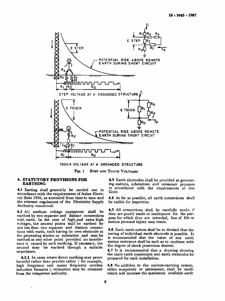
2.35 Voltage, Nominal — Voltage by which an installation ( or part of an installation ) is designated. 2.36 Touch Voltage — The potential difference between a grounded metallic structure and a point on the earth's surface separated by a distance equal to the normal maximum horizontal reach, approximately one metre ( see Fig. 1 ).
2.37 Step Voltage — The potential difference between two points on the earth's surface, separated by distance of one pace, that will be assumed to be one metre in the direction of maximum potential gradient ( see Fig. 1 ). 2.38 Equipotential Line or Contour — The locus of points having the same potential at a given time. 2.39 Mutual Resistance of Grounding Electrodes — Equal to the voltage change in one of them produced by a change of one ampere of direct current in the other and is expressed in ohms.
2.40 Earth Grid — A system of grounding electrodes consisting of inter-connected connectors buried in the earth to provide a common ground for electrical devices and metallic structures.
NOTE—The term 'earth grid' does not include 'earth mat'.
2.41 Earth Mat — A grounding system formed by a grid of horizontally buried conductors and which serves to dissipate the earth fault current to earth and also as an equipotential bonding conductor system.
3. EXCHANGE OF INFORMATION
3.1 When the earthing of a consumer's installation is being planned, prior consultation shall take place between the consultant or contractor and the supply authority. Where necessary, con ;ulta-tions with the Posts & Telegraphs Department shall also be carried out in order to avoid any interference with the telecommunication system.
♦Electrotechnical vocabulary: Part 17 Switchgear and controlgear (first revision).
8
IS i 3043 - 1987
£ STEP
| R IQRF RX
I R0U R1 "*T7
POTENTIAL RISE ABOVE REMOTE EARTH DURING SHORT CIRCUIT
STEP VOLTAGE AT A GROUNDED STRUCTURE j
E TOUCH Rl
]R0 IK
POTENTIAL RISE ABOVE REMOTE EARTH DURING SHORT CIRCUIT
TOUCH VOLTAGE AT A GROUNDED STRUCTURE
Fio. 1 STEP AND TOUCH VOLTAGES
4. STATUTORY PROVISIONS FOR EARTHING
4.1 Earting shall generally be carried out in accordance with the requirements of Indian Electricity Rides 1956, as amended from time to time and the relevant regulations of the Electricity Supply Authority concerned. 4.2 All medium voltage equipment shall be earthed by two separate and distinct connections with earth. In the case of highland extra high voltages, the neutral points shall be earthed by not less than two separate and distinct connections with earth, each having its own electrode at the generating station or substation and may be earthed at any other point provided no interference is caused by such earthing. If necessary, the neutral may be earthed through a suitable impedance.
4.2.1 In cases where direct earthing may prove harmful rather than provide safety ( for example, high frequency and mains frequency coreless induction furnaces ), relaxation may be obtained from the competent authority.
4.3 Earth electrodes shall be provided at generating stations, substations and consumer premises in accordance with the requirements of this Code. .4.4 As far as possible, all earth connections shall be Visible for inspection.
4.5 All connections shall be carefully made; if they are poorly made or inadequate for the purpose for which they are intended, loss of life or serious personal injury may result.
4.6 Each earth system shall be so devised that the testing of individual earth electrode is possible. I t is recommended that the value of any earth system resistance shall be such as to conform with the degree of shock protection desired. 4.7 It is recommended that a drawing showing the main earth connection and earth electrodes be prepared for each installation.
4.8 No addition to the current-carrying system, either temporary or permanent, shall be made which will increase the maximum available earth
9
IS : 3043 . 1987
fault current or its duration until it has been ascertained that the existing arrangement of earth electrodes, earth bus-bar, etc, are capable of carrying the new value of earth fault current which may be obtained by this addition. 4.9 No cut-out, link or switch other than a linked switch arranged to operate simultaneously on the earthed or earthed neutral conductor and the live conductors, shall be inserted on any supply system. This, however, does not include the case of a switch for use in controlling a generator or a transformer or a link for test purposes. 4.10 All materials, fittings, etc, used in earthing shall conform to Indian Standard specifications, wherever these exist.
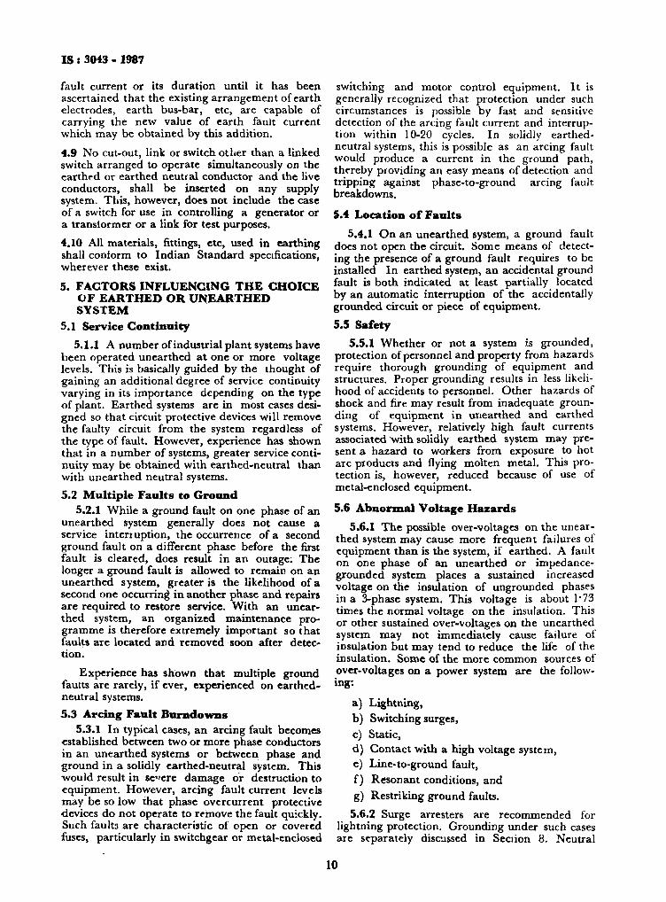
5. FACTORS INFLUENCING THE CHOICE OF EARTHED OR UNEARTHED SYSTEM
5.1 Service Continuity 5.1.1 A number of industrial plant systems have
been operated unearthed at one or more voltage levels. This is basically guided by the thought of gaining an additional degree of service continuity varying in its importance depending on the type of plant. Earthed systems are in most cases designed so that circuit protective devices will remove the faulty circuit from the system regardless of the type of fault. However, experience has shown that in a number of systems, greater service continuity may be obtained with earthed-neutral than with unearthed neutral systems.
5.2 Multiple Faults to Ground 5.2.1 While a ground fault on one phase of an
unearthed system generally does not cause a service interruption, the occurrence of a second ground fault on a different phase before the first fault is cleared, does result in an outage; The longer a ground fault is allowed to remain on an unearthed system, greater is the likelihood of a second one occurring in another phase and repairs are required to restore service. With an unearthed system, an organized maintenance programme is therefore extremely important so that faults are located and removed soon after detection.
Experience has shown that multiple ground faults are rarely, if ever, experienced on earthed-neutral systems. 5.3 Arcing Fault Burndowns
5.3.1 In typical cases, an arcing fault becomes established between two or more phase conductors in an unearthed systems or between phase and ground in a solidly earthed-neutral system. This would result in sce re damage or destruction to equipment. However, arcing fault current levels may be so low that phase overcurrent protective •devices do not operate to remove the fault quickly. Such faults are characteristic of open or covered fuses, particularly in switchgcar or metal-enclosed
switching and motor control equipment. It is generally recognized that protection under such circumstances is possible by fast and sensitive detection of the arcing fault current and interruption within 10-20 cycles. In solidly earthed-neutral systems, this is possible as an arcing fault would produce a current in the ground path, thereby providing an easy means of detection and tripping against phase-to-ground arcing fault breakdowns.
5.4 Location of Faults 5.4.1 On an unearthed system, a ground fault
does not open the circuit. Some means of detecting the presence of a ground fault requires to be installed In earthed system, an accidental ground fault is both indicated at least partially located by an automatic interruption of the accidentally grounded circuit or piece of equipment.
5.5 Safety 5.5.1 Whether or not a system is grounded,
protection of personnel and property from hazards require thorough grounding of equipment and structures. Proper grounding results in less likelihood of accidents to personnel. Other hazards of shock and fire may result from inadequate grounding of equipment in unearthed and earthed systems. However, relatively high fault currents associated with solidly earthed system may present a hazard to workers from exposure to hot arc products and flying molten metal. This protection is, however, reduced because of use of metal-enclosed equipment.
5.6 Abnormal Voltage Hazards 5.6.1 The possible over-voltages on the unear
thed system may cause more frequent failures of equipment than is the system, if earthed. A fault on one phase of an unearthed or impedance-grounded system places a sustained increased voltage on the insulation of ungrounded phases in a 3-phase system. This voltage is about 1*73 times the normal voltage on the insulation. This or other sustained over-voltages on the unearthed system may not immediately cause failure of insulation but may tend to reduce the life of the insulation. Some of the more common sources of over-voltages on a power system are the following:
a) Lightning, b) Switching surges, c) Static, d) Contact with a high voltage system, e) Line-to-ground fault, f) Resonant conditions, and g) Restriking ground faults.
5.6.2 Surge arresters are recommended for lightning protection. Grounding under such cases are separately discussed in Section 8. Neutral
10
IS t 3043 • 1987
grounding is not likely to reduce the total magnitude of over-voltage produced by lightning or switching surges. It can, however, distribute the voltage between phases and reduce the possibility of excessive voltage stress on the phase-to-ground insulation of a particular phase. A system ground connection even of relatively high resistance can effectively prevent static voltage build-up ( see Sec 8 ). Even under conditions of an HV line breaking and falling on an LV system, an effectively grounded LV system will hold the system neutral close to the ground potential thus limiting the over-voltage. An unearthed system will be subjected to resonant over-voltages. Field experience and theoretical studies have shown the world over that arcing, restriking or vibrating ground faults on unearthed systems can, under certain conditions, produce surge voltages as high as 6 times the normal voltage. Neutral grounding is effective in reducing transient build up by reducing the neutral displacement from ground potential and the destructiveness of any high frequency voltage oscillations following each arc initiation or restrike.
5.7 Cost 5.7.1 The cost differential between earthed
and unearthed neutral system will vary, depending on the method of grounding the degree of protection desired, and whether a new or an existing system is to be earthed.
6. SYSTEM EARTHING 6.0 Basic Objectives
6.0.1 Earthing of system is designed primarily to preserve the security of the system by ensuring that the potential on each conductor is restricted to such a value as is consistent with the level of insulation applied. From the point of view of safety, it is equally important that earthing should ensure efficient and fast operation of protective gear in the case of earth faults. Most high voltage public supply systems are earthed. Approval has been given in recent years to unearthed overhead line systems in certain countries, but these have only been small 11 kV systems derived from 33 kV mains, where the capacity earth current is less than 4 A and circumstances are such that the system will not be appreciably extended.
6.0.2 The limitation of earthing to one point on each system is designed to prevent the passage of current through the earth under normal conditions, and thus to avoid the accompanying risks of electrolysis and interference with communication circuits. With a suitable designed system, properly operated and maintained, earthing at several points may be permitted. This method of earthing becomes economically essential in systems at 200 kV and upwards.
6.0.3 The system earth-resistance should be such that, when any fault occurs against which
earthing is designed to give protection, the protective gear will operate to make the faulty main or plant harmless. In most cases, such operation involves isolation of the faulty main or plant, for example, by circuit-breakers or fuses.
6.0.4 In the case of underground systems, there is no difficulty whatever but, for example, in the case of overhead-line systems protected by fuses or circuit-breakers fitted with overcurrent protection only, there may be difficulty in arranging that the value of the system earth-resistance is such that a conductor falling and making good contact with the ground results in operation of the protection. A low system-earth resistance is required even in the cases where an arc-suppression coil is installed, as its operation may be frustrated by too high an earth-electrode resistance.
6.0.5 Earthing may not give protection against faults that are not essentially earth faults. For example, if a phase conductor on an overhead spur line breaks, and the part remote from the supply falls to the ground, it is unlikely that any protective gear relying on earthing, other than current balance protection at the substation, will operate since the earth-fault current circuit includes the impedance of the load that would be high relative to the rest of the circuit.
6.0.6 For the purposes of this code of practice, it is convenient to consider a system as comprising a source of energy and an installation; the former including the supply cables to the latter.
6.1 Classification of Systems Based on Types of System Earthing
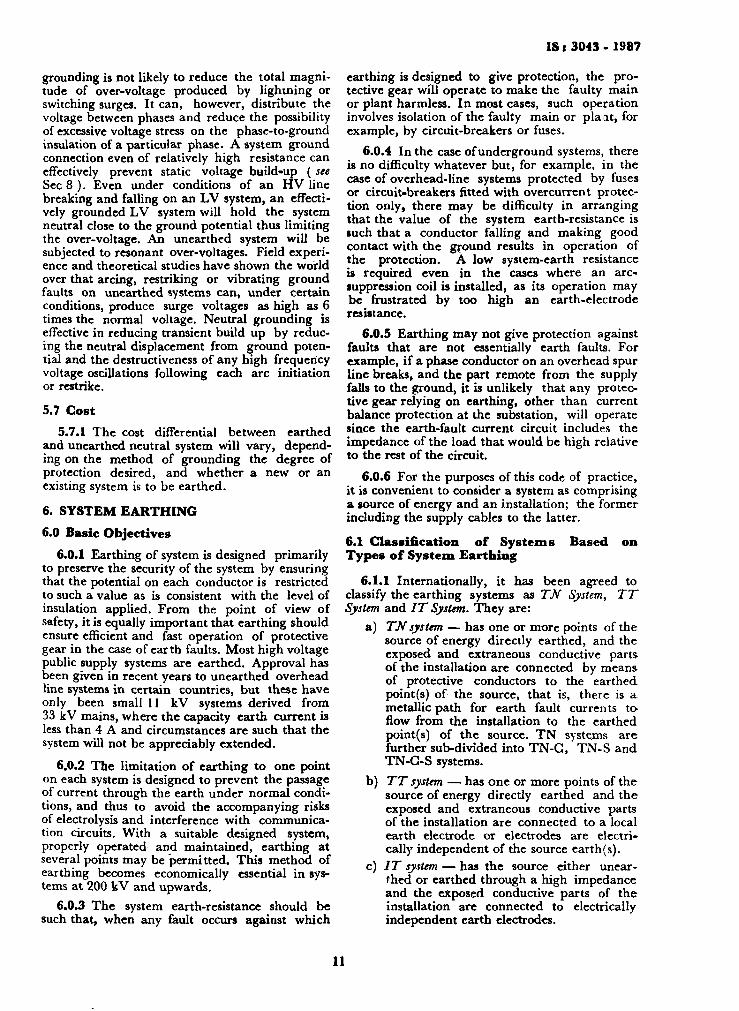
6.1.1 Internationally, it has been agreed to classify the earthing systems as TN System, TT System and IT System. They are:
a) TN system — has one or more points of the source of energy directly earthed, and the exposed and extraneous conductive parts of the installation are connected by means of protective conductors to the earthed point(s) of the source, that is, there is a metallic path for earth fault currents to flow from the installation to the earthed point(s) of the source. TN systerns are further sub-divided into TN-G, TN-S and TN-C-S systems.
b) TT system — has one or more points of the source of energy directly earthed and the exposed and extraneous conductive parts of the installation are connected to a local earth electrode or electrodes are electrically independent of the source earth (s).
c) IT system — has the source either unearthed or earthed through a high impedance and the exposed conductive parts of the installation are connected to electrically independent earth electrodes.
11
I S : 3043 . 1987
6.1.2 It is also recognized that, in practice, a system may be an admixture of type for the purposes of this code, earthing systems are designated as follows:
a)
c)
TN-S System {for 240 V single phase domestic! commercial supply ) — Systems where there are separate neutral and protective conductors throughout the system. A system where the metallic path between the installation and the source of energy is the sheath and armouring of the supply cable ( see Fig. 2 ).
b) Indian TN-S System {for 415 V three-phase domestic commercial supply ) — An independent earth electrode within the consumer's premises is necessary ( See Fig. 3 ). Indian TNC-System—The neutral and protective functons are combined in a single
SOURCE OF ENERGY
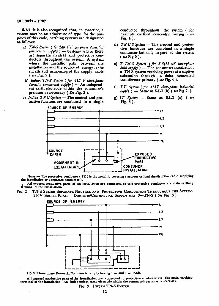
couductor throughout the system ( for example earthed concentric wiring (see Fig. 4 ).
d) TN-C-S Systtm — The neutral and protective functions are combined in a single conductor but only in part of the system ( set Fig 5 ) .
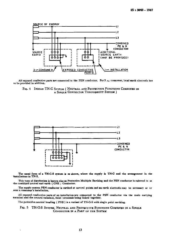
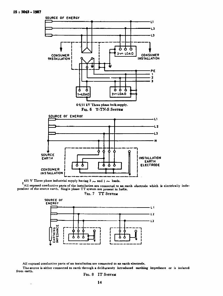
e) T-TN-S System {for 6-6\ll kV thtee-phase bulk supply ) — The consumers installation, a TN-S system receiving power at a captive substation through a delta connected transformer primary ( see Fig. 6 ).
f) TT System {for 415V three-phase industrial supply ) — Same as 6.1.1 (b) ( see Fig 7. ).
g) IT System Fig. 8 ).
Same as 6.1.1 (c) ( see
SOURCE f EARTH {
I EQUIPMENT IN \ INSTALLATION
-L2
-L3
-N
•PE
EXPOSED CONOUCTIVE PART
'CONSUMER INSTALLATION
NOTE — The protective conductor ( FE ) is the metallic covering ( armour or load sheath of the cable supplying the installation or a separate conductor ). . AH exposed conductive parts of an installation are connected to this protective conductor via main earthing terminal of the installation.
Fio. 2 TN-S SYSTEM SEPARATE NEUTRAL AND PROTECTIVE CONDUCTORS THROUGHOUT THE SYSTEM, 230V SIMPLE PHASE. DOMESTIC/COMMERCIAL SUPPLY FOR 3~TN-S ( >SM FIO. 3 )
SOURCE OF ENERGY LI
L2
N
PE
r — _ _
r i < ! J~ i
i ' i i i
— i ; A o
_ 1 i
r-<> A A j
415 V Three phase Domestic/Commercial supply having 3 <~ and 1 r~ loads. All exposed conductive parts of the installation are connected to protective conductor via the main earthing
terminal'of the installation. An independent earth electrode within the consumer's permises is necessary. FIO. 3 INDIAN TN-S SYSTEM
12
IS t 3843 • 1987
SOURCE OF ENERGY
SOURC EART
CE I 0
" i It v.^ 3 ^CONSUMER / \EXPOSEO CONDUCTIVE \ \ ^
— LI
— L2
— 1 3
—COMBINEO PE & N
CONDUCTOR I ADDITIONAL I SOURCE EARTH j (MAY BE PROVIDED) I
T
•-> INSTALLATION PARTS
All exposed conductive parts are connected to the PEN conductor. For 3 /— consumer, local earth electrode has to be provided in addition.
Fio. 4 INDIAN TN-C SYSTEM ( NEUTRAL AND PROTECTIVE FUNCTIONS COMBINED IN A SINGLE CONDUCTOR THROUGHOUT SYSTEM )
COMBINED PE &. N
C0N0UCTDR
The usual form of a TN-C-S system it at shown, where the supply it TN-C and the arrangement in the installations in TN-S.
This type of distribution is known also as Protective Multiple Earthing and the PEN conductor it referred to as the combined neutral and earth ( CNE ) Conductor.
The supply system PEN conductor is earthed at several points and an earth electrode may be necessary at or near a consumer's installation.
All exposed conductive parts of an installation are connected to the PEN conductor via the main earthing terminal and the neutral terminal, these terminals being linked together.
The protective neutral bonding ( PNB ) is a variant of TN-C-S with single point earthing.
FIQ. 5 TN-C-S SYSTEM, NEUTRAL AND PROTECTIVE FUNCTIONS COMBINED IN A SINGLE CONDUCTOR IN A PART OF THE SYSTEM
13
IS t 3043 • 1987 SOURCE OF ENERGY
rr CONSUMER
INSTALLATION
I - ,
< 1«
<>
" " T"
i ! |
ii i iJ-6 6 6
' 3 ^ LOAD 1
CONSUMER INSTALLATION
^ *
1 A
>LOAD t_
6 6 6 ' 3~LOAD <
66/11 kV Three phase bulk supply. Fio. 6 T-TN-S SYSTEM
SOURCE OF ENERGY
SOURCE EARTH
CONSUMER | INSTALLATION |
if J (i 0 v
■LI
-L2
■L3
■N
6 6 6 T3L
NSTALLATION EARTH
ELECTRODE
415 V Three phase industrial supply having 3 r~ and 1 ~ loads. All exposed conductive parts of the installation are connected to an earth electrode which is electrically inde
pendent of the source earth. Single phase T T system not present in India. Fio. 7 TT SYSTEM
SOURCE OF ENERGY
X^ !_.' L J 1 J L
All exposed conductive parts of an installation are connected to an earth eleetrode. The source is either connected to earth through a deliberately introduced earthing impedance or is isolated
from earth. Fio. 8 IT SYSTEM
14
IS : 3043 < 1987
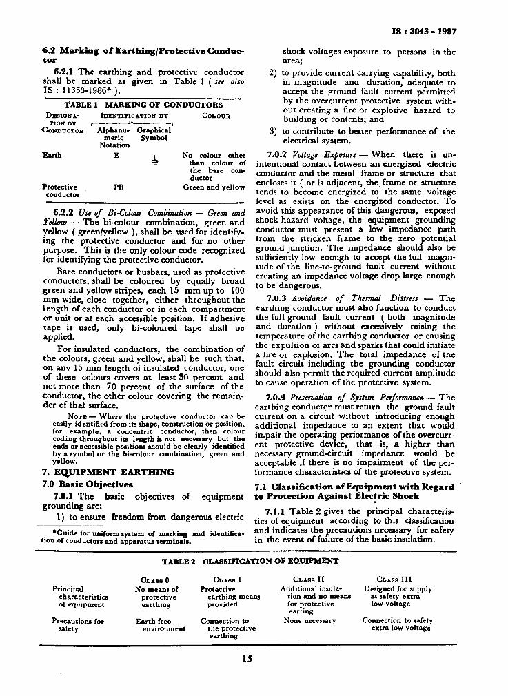
6.2 Marking of Earthing/Protective Conductor
6.2.1 The earthing and protective conductor shall be marked as given in Table 1 ( see also IS : 11353-1986*).
TABLE 1 MARKING OF CONDUCTORS D E S I G N A
TION o» CONDUCTOR
Earth
Protective conductor
IDENTIFICATION B Y * , Alphanu- Graphical
meric Symbol Notation
PB
CoLOTJB
No colour other than colour of the bare conductor
Green and yellow
6.2.2 Use of Bi-Colour Combination — Green and Yellow — The bi-colour combination, green and yellow ( green/yellow ), shall be used for identifying the protective conductor and for no other purpose. This is the only colour code recognized for identifying the protective conductor.
Bare conductors or busbars, used as protective conductors, shall be coloured by equally broad green and yellow stripes, each 15 mm up to 100 mm wide, close together, either throughout the length of each conductor or in each compartment or unit or at each accessible position. If adhesive tape is used, only bi-coloured tape shall be applied.
For insulated conductors, the combination of the colours, green and yellow, shall be such that, on any 15 mm length of insulated conductor, one of these colours covers at least 30 percent and not more than 70 percent of the surface of the conductor, the other colour covering the remainder of that surface.
N O T E — Where the protective conductor can be easily identified from its shape, Construction or position, for example, a concentric conductor, then colour coding throughout its length is not necessary but the ends or accessible positions should be clearly identified by a symbol or the bi-colour combination, green and yellow.
7. EQUIPMENT EARTHING 7.0 Basic Objectives
7.0.1 The basic objectives of equipment grounding are:
1) to ensure freedom from dangerous electric
•Guide for uniform system of marking and identification of conductors and apparatus terminals.
shock voltages exposure to persons in the area;
2) to provide current carrying capability, both in magnitude and duration, adequate to accept the ground fault current permitted by the overcurrent protective system without creating a fire or explosive hazard to building or contents; and
3) to contribute to better performance of the electrical system.
7.0.2 Voltage Exposure — When there is unintentional contact between an energized electric conductor and the metal frame or structure that encloses it ( or is adjacent, the frame or structure tends to become energized to the same voltage level as exists on the energized conductor. To avoid this appearance of this dangerous, exposed shock hazard voltage, the equipment grounding conductor must present a low impedance path from the stricken frame to the zero potential ground junction. The impedance should also be sufficiently low enough to accept the full magnitude of the line-to-ground fault current without creating an impedance voltage drop large enough to be dangerous.
7.0.3 Avoidance of Thermal Distress — The earthing conductor must also function to conduct the full ground fault current ( both magnitude and duration) without excessively raising the temperature of the earthing conductor or causing the expulsion of arcs and sparks that could initiate a fire or explosion. The total impedance of the fault circuit including the grounding conductor should also permit the required current amplitude to cause operation of the protective system.
7.0.4 Preservation of System Performance?— The earthing conductor must return the ground fault current on a circuit without introducing enough additional impedance to an extent that would impair the operating performance of the overcurrent protective device, that is, a higher than necessary ground-circuit impedance would be acceptable if there is no impairment of the performance characteristics of the protective system.
7.1 Classification of Equipment with Regard to Protection Against Electric Shock
7.1.1 Table 2 gives the principal characteristics of equipment according to this classification and indicates the precautions necessary for safety in the event of failure of the basic insulation.
TABLE 2 CLASSIFICATION OF EQUIPMENT
Principal characteristics of equipment
Precautions for safety
C L A S S 0 No means of
protective earthing
Earth free environment
C L A S S I Protective
earthing means provided
Connection to the protective earthing
C L A S S I I Additional insula
tion and no means for protective earting
None necessary
C L A S S I I I Designed for supply
at safety extra low voltage
Connection to safety extra low voltage
15

IS : 3043 - 1987
SECTION 2 CONNECTIONS TO EARTH
8. RESISTANCE TO EARTH 8.0 Nature of Earthing Resistance
8.0.1 The earthing resistance of an electrode is made up of:
a) resistance of the ( metal ) electrode, b) contact resistance between the electrode
and the soil, and c) resistance of the soil from the electrode sur
face outward in the geometry set up for the flow of current outward from the electrode to infinite earth;
The first two factors are very small fractions of an ohm and can be neglected for all practical purposes. The factor of soil resistivity is discussed in 8.1. 8.1 Soil Resistivity
8.1.1 The resistance to earth of a given electrode depends upon the electrical resistivity of the soil in which it is installed. This factor is, therefore, important in deciding which of many protective systems to adopt.
The type of soil largely determines its resistivity and examples are given in Table 3. Earth conductivity is, however, essentially electrolytic in nature and is affected, by the moisture content of the soil and by the chemical composition and
concentration of salts dissolved in the contained water. Grain size and distribution, and closeness-of packing are also contributory factors since they control the manner in which the moisture is held in the soil. Many of these factors vary locally and some seasonally so that the table should only be taken as a general guide.
Local values should be verified by actual measurement, and this is especially important where the soil is stratified as, owing to the dispersion of the earth current, the effective resistivity depends not only on the surface layers but also on the underlying geological formation.
It should also be noted that soil temperature has some effect ( see 8.7 ), but is only important near and below freezing point, necessitating the installation of earth electrodes at depths to which frost will not penetrate. It is, therefore, recommended that the first metre of any earth electrode should not be regarded as being effective under frost conditions.
While the fundamental nature and properties of a soil in a given area cannot be changed, use can be made of purely local conditions in choosing suitable electrode sites and methods of preparing the site selected to secure the optimum resistivity. These measures may be summarized as in 8.2 to 8.7.
T Y P E o r SOIL
TABLE 3 EXAMPLES OF SOIL RESISTIVITY
CLIMATIC COKDITION
(1)
Alluvium and lighter clays Clays ( excluding alluvium ) Marls ( for example, keuper marl ) Porous lime&tone ( for example, chalk ) Porous sandstone (for example, keuper
sandstone and clay shales ) Quartzites, compact and crystalline
limestone ( for example, carboniferous marble, etc )
Clay slates and slatey shales Granite
Fossile slates, schists gneiss igneous rocks
r— - ' ■■ ■" - '■ ■-
Normal and High Low Rainfall and Rainfall ( For Desert Condition ( For
Example, Greater Examples, Less than than 500 mm a Year ) 250 mm a Year )
Probable Range of value values
encountered (2) (3) Q.m i i .m
5 • 10 5 to 20 20 10 to 30 50 30 to 100
100 30 to 300
300 100 to 1 000
1 000 300 to 3 000 1 000
2 000 1 000 upwards
Range of values
encountered (4)
Q.m •
10 to 100 50 to 300
1 000 upwards
Underground Waters
( Saline )
Range of values
encountered (5)
Q.m
1 to 5
30 to 100
•Depends on water level of locality
16

IS < 3043 • 1987
8.2 Where there is any option, a site should be chosen in one of the following types of soil in the order of preference given:
a) Wet marshy ground ( see8.3 ); b) Clay, loamy soil, arable land, clayey soil,
clayey soil or loam mixed with small quantities of sand;
c) Clay and loam mixed with varying proportions of sand, gravel and stones;
d) D a m p and wet sand, peat.
Dry sand, gravel chalk, limestone, granite and any very stony ground should be avoided, and also all locations where virgin rock i s very close to the surface.
8.3 A site should be chosen that is not naturally well-drained. A water-logged situation is not, however, essential, unless the soil is sand or gravel, as in general no advantage results from an increase in moisture content above about 15 to 20 percent. Care should be taken to avoid a site kept moist by water flowing over it ( for example, the bed of a stream ) as the beneficial salts may be entirely removed from the soil in such situations.
8.4 Where building has taken place, the site conditions may be altered by disturbance of the local stratification and natural geological formation when the electrodes have to be installed in this disturbed area.
If a cut and fill exercise has been carried out then the top layer may be similar to the natural formation but increased in depth , whether it is good or bad in terms of resistivity.
If an imported fill exercise has been carried out, the conditions of the upper layers may be altered considerably.
In these cases, deeper driving of the electrode may be necessary to reach layers of reasonable resistivity and also to reach stable ground, such that the value of the electrode resistance remains stable if t he top layers of the ground dry out.
8.5 Soil t reatment to improve earth electrode contact resistance may be applied in special or difficult locations, but migration and leaching of applied chemicals over a period of time reduces the efficiency of the system progressively, requiring constant monitoring and replacement of the additives. Ecological considerations are inherent before such t rea tment is commenced and any deleterious effect upon electrode material has to be taken into account. However , for some temporary electrical installations in areas of high ground resistivity, this may be the most economic method for obtaining satisfactory earth contact over a short period of working. If a greater degree of permanence is envisaged, ear th electrodes packaged in material such as bentonite are preferable.
Bentonite or similar material may be used to advantage in rocky terrain. Where holes are bored
for the insertion of vertical electrodes or where strip electrodes are laid radially under shallow areas of low resistivity overlaying rock strata, bentonite packing will increase the contact efficiency with the general mass of ground.
8.6 Effect o f M o i s t u r e C o n t e n t o n E a r t h R e s i s t i v i t y — Moisture content is one of the controlling factors in earth resistivity. Figure 9 shows the variation of resistivity of red clay soil with percentage of moisture. The moisture content is expressed in percent by weight of the dry soil. Dry earth weighs about 1 440 kg per cubic metre and thus 10 percent moisture content is equivalent to 144 kg of water per cubic metre of dry soil. I t will be seen from Fig. 9 that above about 20 percent moisture, the resistivity is very little affected, while below 20 percent the resistivity increases very abruptly with the decrease in moisture content. A difference of a few percent moisture will therefore, make a very marked difference in the effectiveness of ea r th connection if the moisture content falls below 20 percent. T h e normal moisture content of soils ranges from 10 percent in dry seasons to 35 percent in wet seasons, and an approximate average may be perhaps 16 to 18 percent.
I t should be recognized, however, that moisture alone is not the predominant factor in the low resistivity of soils; for example, ear th electrodes driven directly in the beds of rivers or mountain streams may present very high resistance to ear th . If the water is relatively pure, it will be high resistivity and unless the soil contains sufficient natura l elements to form a conducting electrolyte, the abundance of water will not provide the soil with adequate conductivity. T h e value ' o f high moisture content in soils is advantageous in increasing the solubility of existing natural elements in the soil, and in providing for the solubility of ingredients which may be artificially introduced to improve the soil conductivity.
8.7 Effect o f T e m p e r a t u r e o n Ear th R e s i s t a n c e — T h e temperature coefficient of resistivity for soil is negative, but is negligible for temperatures above freezing point . At about 20°C, the resistivity change is about 9 percent per degree Celsius. Below 0°C t h e water in the soil begins t o freeze and introduces a tremendous increase in the temperature coefficient, so tha t as the temperature becomes lower the resistivity rises enormously. I t is, therefore, recommended that in areas where the temperature is expected to be quite low, the earth electrodes should be installed well below the frost line. Where winter seasons are severe, th is may be about 2 metres below the surface, whereas in mild climates the frost may penetrate only a few centimetres or perhaps the ground may not freeze at all. Ear th electrodes which are not driven below the first depth may have a very great variation in resistance throughout the seasons of the year. Even when driven below the frost line, there is some variation, because the upper soil, when
17

IS : 3043 - 1987
frozen, presents a decided increase in soil resistivity and has the effect of shortening the active length of electrode in contact with soil of normal resistivity. 8.8 Artificial T r e a t m e n t of Soil — Multiple rods, even in large number, may sometime fail to produce an adequately low resistance to earth. This condition arises in installations involving soils of high resistivity. The alternative is to reduce the resistivity of the soil immediately surrounding the earth electrode. To reduce the soil resistivity, it is necessary to dissolve in the moisture, normally contained in the soil, some substance which is highly conductive in its water solution. The most commonly used substances are sodium chloride ( NaCl ), also known as common salt, calcium chloride ( CaClj ), sodium carbonate ( Na sCO s ), copper sulphate ( CuS04 ), salt, and soft coke, and salt and charcoal in suitable proportions.
8.8.1 With average or high moisture content, these agents form a conducting electrolyte throughout a wide region surrounding the earth electrode. Approximately 90 percent of the resistance between a driven rod and earth lies within a radius of about two metres from the rod. This should be kept in mind when applying the agents for artificial treatment of soil. The simplest application is by excavating a shallow basin around the top of the rod, one metre in diameter and about 30 cm deep, and applying the artificial agent in this basin. The basin should subsequently be filled several times with water, which should be allowed each time to soak into the ground, thus carrying the artificial treatment, in electrolyte form, to considerable depths and allowing the artificial agent to become diffused throughout the greater part of the effective cylinder of earth surrounding the driven rod.
400
300
200
o
* >-> f—
100
it
'"
.
4 ■
1_ _
-E T 1 A
=--=E-EEEEEEE============ 0 5 K) 15 20 25 30 35 40 45 50 55 60 65 70
MOISTURE IN SOIL,PERCENT
FIG. 9 VARIATION OF SOIL RESISTIVITY WITH MOISTURE CONTENT
18
IS : 3043 • 2987
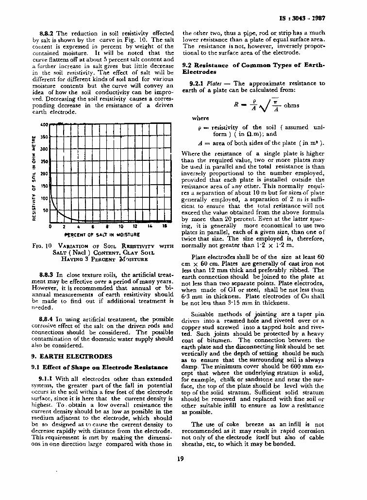
8.8.2 The reduction in soil resistivity effected by salt is shown by the curve in Fig. 10. The salt content is expressed in percent by weight of the contained moisture. It will be noted that the curve flattens off at about 5 percent salt content and a further increase in salt gives but little decrease in the soil resistivity. The effect of salt will be different for different kinds of soil and for various moisture contents but the curve will convey an idea of how the soil conductivity can be improved. Decreasing the soil resistivity causes a corresponding decrease in the resistance of a driven earth electrode.
Ul a «-b l 5 5
5 ? =? c in «fc o * ■
»-> « VI u <£
400
350
300
240
200
1*0
too sn
0 2 4 6 « 10 12 1 * IB
PERCENT OF SALT IN MOISTURE
Fio. 10 VARIATION OF SOIL RESISTIVITY WITH SALT ( Nacl ) CONTENT, CLAY SOIL
HAVING 3 PERCENT MOISTURE
8.8.3 In close texture soils, the artificial treatment may be effective over a period of many years. However, it is recommended that annual or biannual measurements of earth resistivity should be made to find out if additional treatment is needed.
8.8.4 In using artificial treatment, the possible corrosive effect of the salt on the driven rods and connections should be considered. The possible contamination of the domestic water supply should also be considered.
9. EARTH ELECTRODES 9.1 Effect of Shape on Electrode Resistance
9.1.1 With all electrodes other than extended systems, the greater part of the fall in potential occurs in the soil within a few feet of the electrode surface, since it is here that the current density is highest. To. obtain a low overall resistance the current density should be as low as possible in the medium adjacent to the electrode, which should be so designed as to cause the current density to decrease rapidly with distance from the electrode. This requirement is met by making the dimensions in one direction large compared with those in
the other two, thus a pipe, rod or strip has a much lower resistance than a plate of equal surface area. The resistance is not, however, inversely proportional to the surface area of the electrode.
9.2 Resistance of Common Types of Earth-Electrodes
9.2.1 Plates — The approximate resistance to earth of a plate can be calculated from:
R~ i:\/irohms
where p «■= resistivity of the soil ( assumed uni
form ) ( in Q.m); and A = area of both sides of the plate (in m* ).
Where the resistance of a single plate is higher than the required value, two or more plates may be used in parallel and the total resistance is than inversely proportional to the number employed, provided that each plate is installed outside the resistance area of any other. This normally requires a separation of about 10 m but for sizes of plate generally employed, a separation of 2 ni is sufficient to ensure that the total resistance will not exceed the value obtained from the above formula by more than 20 percent. Even at the latter spacing, it is generally more economical to use two plates in parallel, each of a given size, than one of twice that size. The size employed is, therefore, normally not greater than 12 x l ' 2 m .
Plate electrodes shall be of the size at least 60 cm x 60 cm. Plates are generally of cast iron not less than 12 mm thick and preferably ribbed. The earth connection should be joined to the plate at not less than two separate points. Plate electrodes, when made of GI or steel, shall be not less than 6*3 mm in thickness. Plate electrodes of Cu shalL be not less than 3*15 mm in thickness.
Suitable methods of jointing are a taper pin-driven into a reamed hole and riveted over or a copper stud screwed into a tapped hole and riveted. Such joints should be protected by a heavy coat of bitumen. The connection between the earth plate and the disconnecting link should be set vertically and the depth of setting should be such as to ensure that the surrounding soil is always damp The minimum cover should be 600 mm except that where the underlying stratum is solid, for example, chalk or sandstone and near the surface, the top of the plate should be level with the top of the solid stratum. Sufficient solid stratum should be removed and replaced with fine soil or other suitable infill to ensure as low a resistance as possible.
The use of coke breeze as an infill is not recommended as it may result in rapid corrosion not only of the electrode itself but also of cable sheaths, etc, to which it may be bonded.
19
IS i 3043 • 1987
The resistance R ( in O ) of a 1-2 m x 1*2 m plate is given approximately by the formula:
R 275 For conventional sizes, the resistance is appro
ximately inversely proportional to the linear dimensions, not the surface area, that is a 0*9 m x 0*9 m plate would have a resistance approximately 25 percent higher than a 12 x 12 m plate. The current loading capacity of a 1*2 m x l ' 2 m plate is of the order of 1 600 A for 2 s and 1 300 A for 3 s.
Plate electrodes shall be buried such that its top edge is at a depth not less than 1 5 m from the surface of the ground. However, the depth at which plates are set should be such as to ensure that the surrounding soil is always damp. Where the underlying stratum is solid, for example chalk or sandstone and near the surface, the top of the plate should be approximately level with the top of the solid stratum.
9.2.2 Pipes or Rods — The resistance of a pipe or rod electrode is given by:
R
where
100 p 2 T C /
log0 —T- ohms
/ = length of rod or pipe ( in cm ), d = diameter of rod or pipe in cm, and p «= resistivity of the soil ( in £}.m )
( assumed uniform ).
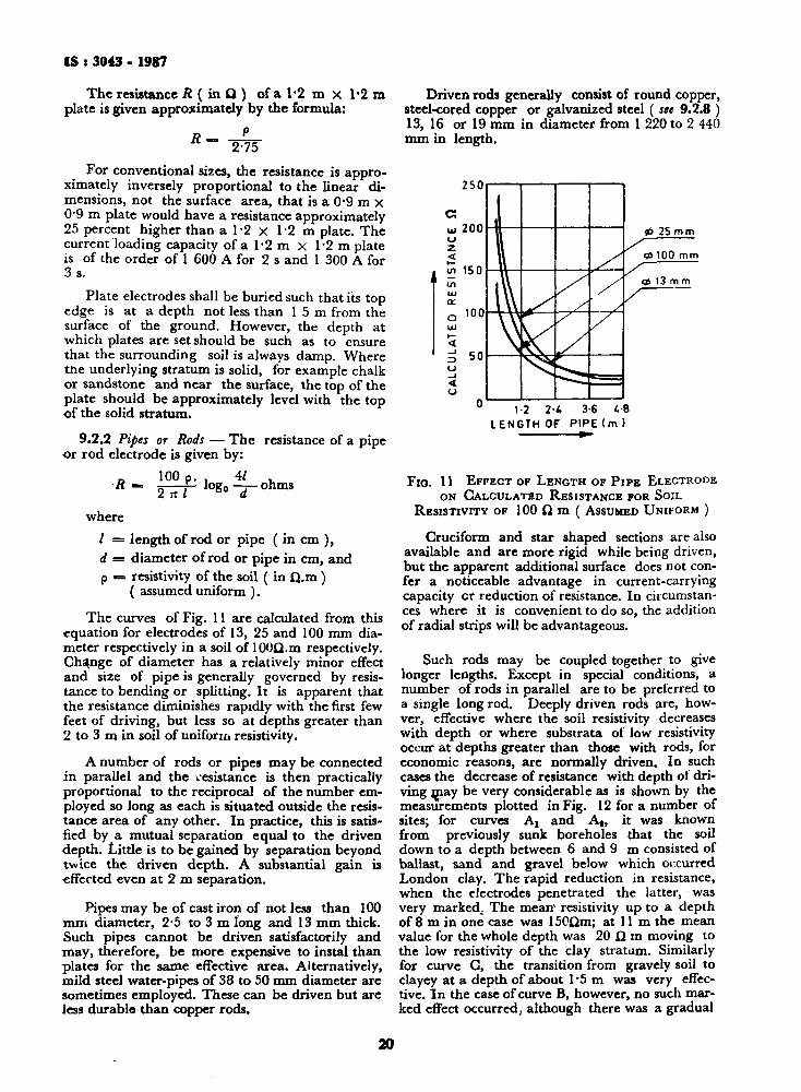
The curves of Fig. 11 are calculated from this equation for electrodes of 13, 25 and 100 mm diameter respectively in a soil of lOOQ.m respectively. Change of diameter has a relatively minor effect and size of pipe is generally governed by resistance to bending or splitting.lt is apparent that the resistance diminishes rapidly with the first few feet of driving, but less so at depths greater than 2 to 3 m in soil of uniform resistivity.
A number of rods or pipes may be connected in parallel and the resistance is then practically proportional to the reciprocal of the number employed so long as each is situated outside the resistance area of any other. In practice, this is satisfied by a mutual separation equal to the driven depth. Little is to be gained by separation beyond tvvice the driven depth. A substantial gain is effected even at 2 m separation.
Pipes may be of cast iron of not less than 100 mm diameter, 2-5 to 3 m long and 13 mm thick. Such pipes cannot be driven satisfactorily and may, therefore, be more expensive to instal than plates for the same effective area. Alternatively, mild steel water-pipes of 38 to 50 mm diameter are sometimes employed. These can be driven but are less durable than copper rods.
Driven rods generally consist of round copper, steel-cored copper or galvanized steel ( see 9.2.8 ) 13, 16 or 19 mm in diameter from 1 220 to 2 440 mm in length.
2S0
w 200 o z < v> 150 UJ
a. 100
ID u <
50
/ / /
1-2 2-i. 3-6 4-8 LENGTH OF PIPE ( m )
& 25 mm
<t> 100 mm
qk 13 m m
Fio. 11 EFFECT OF LENGTH OF P I P E ELECTRODE ON CALCULATED RESISTANCE FOR SOIL
RESISTIVITY OF 100 Q m ( ASSUMED UNIFORM )
Cruciform and star shaped sections are also available and are more rigid while being driven, but the apparent additional surface does not confer a noticeable advantage in current-carrying capacity or reduction of resistance. In circumstances where it is convenient to do so, the addition of radial strips will be advantageous.
Such rods may be coupled together to give longer lengths. Except in special conditions, a number of rods in parallel are to be preferred to a single long rod. Deeply driven rods are, how-ver, effective where the soil resistivity decreases with depth or where substrata of low resistivity occur at depths greater than those with rods, for economic reasons, are normally driven. In such cases the decrease of resistance with depth of driving may be very considerable as is shown by the measurements plotted in Fig. 12 for a number of sites; for curves Ax and A t, it was known from previously sunk boreholes that the soil down to a depth between 6 and 9 m consisted of ballast, sand and gravel below which occurred London clay. The rapid reduction in resistance, when the electrodes penetrated the latter, was very marked.. The mean resistivity up to a depth of 8 m in one case was 150Qm; at 11 m the mean value for the whole depth was 20 Cl m moving to the low resistivity of the clay stratum. Similarly for curve C, the transition from gravely soil to clayey at a depth of about 1 -5 m was very effective. In the case of curve B, however, no such marked effect occurred; although there was a gradual
20

IS t 3043 - 1987
a
300
200
100 ao
40
20 u z < w 10 (/> 8 ui u. 6
P = 20 000flcrr.
PrIQOOOficm
•~ \ .Ap = 5000n cm
LENGTH OF DRIVEN ELECTRODE m *»-
Fio. 12 CALCULATED AND EXPERIMENTAL CURVES OF RESISTANCE OF 13 mm DIA DRIVEN ELECTRODES
reduction in average resistivity with increase in depth, as can be seen by comparison with the dotted curves, which are calculated on the assumption of uniform resistivity.
Other factors that affect a decision whether to drive deep electrodes or to employ several rods or pipes in parallel are the steep rise in the energy required to drive them with increase in depth and the cost of couplings. The former can be offset by reducing die diameter of the rods, since a 13 mm diameter rod can be driven to considerable depths without deformation or bending if the technique of using a large number of comparatively light blows is adopted rather than a smaller number of blows with a sledge hammer. Power-driven hammers suitable for this purpose are available.
In cases where impenetrable strata or high-resistivity soil occur at relatively small depths, considerable advantage may result from driving rods at an angle of about 30° to the horizontal, thus increasing the length installed for a given depth.
9.2.3 Strip or Conductor Electrodes — These have special advantages where high resistivity soil underlies shallow surface layers of low resistivity. The minimum cross-sectional area of strip electro
des shall be according to 12.1.1. If round conductors are used as earth electrodes, their cross-sectional area shall inot be less than the sizes recommended for strip electrodes. The resistance R is given by:
where
lOOp 2*/ loge _2/*_
w t ohms
p — resistivity of the soil ( i n Q.m ) ( assumed uniform);
/ = length of the strip in cm;
w «= depth of burial of the electrode in cm; and
t = width ( in the case of strip ) or twice the diameter ( fir conductors ) in cm.
Care should be taken in positioning these electrodes, especially to avoid damage by agricultural operations.
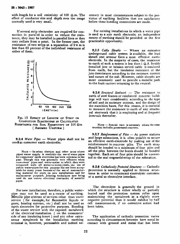
Figure 13 shows the variation oi calculated earth-resistance of strip or conductor electrodes
21
IS : 3043 * 1987
with length for a soil resistivity of 100 Q.m. The effect of conductor size and depth over the range normally used is very small.
cessary in most circumstances subject to the provision of earthing facilities that are satisfactory before these bonding connections are made.
If several strip electrodes are required for connection in parallel in order to reduce the resistance, they may be installed in parallel lines or they may radiate from a point. In the former case, the resistance of two strips at a separation of 2*4 m is less than 65 percent of the individual resistance of either of them.
60 120 180 240 LENGTH(m)
300
FIG. 13 EFFECT OF LENGTH OF STRIP OR CONDUCTOR ELECTRODES IN CALCULATED
RESISTANCE FOR SOIL RESISTIVITY OF 100 fim ( ASSUMED UNIFORM )
9.2.4 Water Pipes — Water pipes shall not be usedjas consumer earth electrodes.
NOTE — In urban districts and other areas where piped water supply is available the use of water pipes for consumers' earth electrodes has been common in the past. Though this was generally very effective when consumers' pipes and water-mains to which they were connected were all metal-to-metal joints, the use of public water-pipes for this purpose has not been acceptable for many years because of the use of nonconducting material for pipes on new installations and for replacement purposes. Jointing techniques now being used do not ensure electrical continuity of metallic pipes.
For new installations, therefore, a public water-pipe may not be used as a means of earthing. Metallic pipe systems of services other than water service ( for example, for flammable liquids or gases, heating systems, etc ) shall not be used as earth electrodes for protective purposes. Bonding of the water service with the exposed metalwork of the electrical installation ( on the consumers' side of any insulating insert ) and any other extraneous metalwork to the installation earthing terminal is, however, permissible and indeed ne-
For existing installations in which a water pipe is used as a sole earth electrode; an independent means of earthing should be provided at the first practicable opportunity.
9.2.5 Cable Sheaths — Where an extensive underground cable system is available, the lead sheath and armour form a most effective earth-electrode. In the majority of cases, the resistance to earth of such a system is less than 1 Q.A freshly installed jute or hessian served cable is insulated from earth, but the insulation resistance of the jute deteriorates according to the moisture content and nature of the soil. However, cable sheaths are more commonly used to provide a metallic path to the fault current returning to the neutral.
9.2.6 Structural Steelwork — The resistance to earth of steel frames or reinforced concrete buildings will vary considerably according to the type of soil and its moisture content, and the design of the stanchion bases. For this reason, it is essential to measure the resistance to earth of any structural steetwork that it is employing and at frequent intervals thereafter.
NOTE — Special care is necessary truction includes prestressed concrete.
where the cons-
9.2.7 Reinforcement of Piles — At power stations and large substations, it is often possible to secure an effective earth-electrode by making use of the reinforcement in concrete piles. The earth strap should be bonded to a minimum of four piles and all the piles between the bonds should be bonded together. Each set of four piles should be connected to the mai nngearthi-strap of the substation.
9.2.8 Cathodically Protected Structures — Cathodic protection is normally applied to ferrous structures in order to counteract electrolytic corrosion at a metal to electrolyte interface.
The electrolyte is generally the ground in which the structure is either wholly or partially buried and the protection system relies upon maintaining the metalwork at a slightly more negative potential than it would exhibit by half cell measurements, if no corrective action had been taken.
The application of cathodic protection varies according to circumstances between bare metal in contact with ground and metal that has been
22
IS : 3043 - 1987
deliberately coated or wrapped against corrosion. In the latter case, cathodic protection is used to supplement the coating and guard against localized corrosion due to coating flaws or faults. Protective system current drain is proportional to the area of bare metal in earth contact and if a normal earthing electrode is attached to a cathodically protected structure, the increased drain current taken by the electrode could be completely unacceptable. This is especially true where the system has been designed to protect a well wrapped or coated structure.
Nevertheless, there may be a necessity to connect earth electrodes to cathodically protected structures, especially where the coating or wrapping tends to electrically insulate the structure from ground, for example:
a) diversion of earth fault currents from electrical apparatus mounted on the structure;
b) diversion of stray current to ground, a problem often met where well coated pipelines ire substantially parallel to the route of a
high voltage overhead line; c) prevention of elevated voltages where struc
tures encroach into hazardous ( flammable ) areas; and
d) Prevention of power surges into the apparatus providing cathodic protection, or similar invasion of delicate low current instrumentation circuits.
In addition to the guidance given in- 9.3, selection of metals for earth electrodes and determination of their ground contact area is most important where cathodically protected structures are involved.
The material selected should exhibit a galvanic potential with respect to ground as nearly equal to that exhibited by the structure in its natural or unprotected condition. For ferrous structures, austenitic iron ( austenitic cast nickel chromium alloy with spheroidal graphite present ) is often used. Vertically driven rods of this material are preferred in order to minimize contact area and thus reduce cathodic protection drain, whilst obtaining optimum performance from the electrode. Copper should be avoided, wherever possible, not only for its increased drain but also for its ability to become cathodic to the protected structure. Magnesium or zinc electrodes have been used successfully, but are anodic to the protected structure and thus sacrificial in action.
9.3 Selection of Metals for Earth-Electrodes — Although electrode material does not affect initial earth resistance, care should be taken to select a material that is resistant to corrosion in the type of soil in which it will be used. Tests in a wide variety of soils have shown that copper, whether
tinned or not, is entirely satisfactory ( subject to the precautions given in this subclause), the average loss in weight of specimens 150 mm X 25 mm X 3 mm buried for 12 years in no case exceed 0*2 percent per year. Corresponding average losses for unprotected ferrous specimens ( for example, cast iron, wrought iron or mild steel) used in the tests were as high as 2"2 percent per year. Considerable and apparently permanent protection appears to be given to mild steel by galvanizing, the test showing galvanized mild steel to be little inferior to copper with an average loss not greater than 0'5 percent per year. Only in a few cases was there any indication in all these tests that corrosion was accelerating and in these cases the indications were not very significant.
The possibility on damage to cables and other underground services and structural metalwork in the vicinity of earth-electrode due to electrolytic action between dissimilar materials should not be overlooked when the material for earth-electrodes is selected. Materials compatible with other metal structures in the vicinity should be selected or other remedial action taken.
It may be essential to use materials of types other than those mentioned earlier in special circumstances, when cathodically protected structures such as pipelines are encountered.
A modern high pressure gas pipeline, wrapped and cathodically protected may have a galvanic potential of — 0 5 V, the accepted material of copper for an earth electrode with a galvanic potential of —0 2 V decreases the total galvanic voltage and increases the need for current from the corrosion protection impressed current system, when the earth electrode is connected to the pipeline.
An earth electrode with a galvanic potential nearer to the protected structure has, to be used to overcome the above and be certain the pipeline is being protected. Such a material is termed an austenitic iron and is an austenitic cast nickel-chromium alloy, with spheroidal graphite present.
It may be necessary to earth the pipeline for one or more of the following reasons:
a) It should not 'on its own be a carrier of any low voltage fault current,
b) It may have low voltage equipment connected to it, for example, for the purpose of valve operation;
c) It may have instrumentation connected to it that require it to be earthed for this purpose and to provide a signal reference earth as well as for earthing requirement relative to electrical equipment used in hazardous areas; and
23
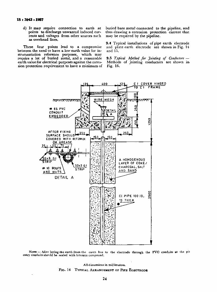
IS > 3043 • 1987
d) It may require connection to earth at points to discharge unwanted induced currents and voltages from other sources such as overhead lines.
These four points lead to a compromise between the need to have a low earth value for instrumentation reference purposes, which may require a lot of buried metal, and a reasonable earth value for electrical purpose's against the corrosion protection requirement to have a minimum of
buried bare metal connected to the pipeline, and thus drawing a corrosion protection current that may be required by the pipeline.
9.4 Typical installations of pipe earth electrode and plate earth electrode are shown in Fig. 14 and 15.
9.5 Typical M,ethod for Jointing of Conductors — Methods of jointing conductors are shown in Fig. 16.
•J25.
* 65 PVC CONDUIT EMBEDDED
400 JlXi jjjjj/f-. ZEE^29jT/
AFTER FIXING SURFACE SHOULD COVERED WITH BITUMIN
OR GREASE
MESH 'J-'Jfi.
I DETAIL ■ & #
11 » ■ <-J!T*»\__
C I COVER HINGED "TO C I FRAME
v^V/i sv/As
o
NOTE — After laying the earth from the earth bus to the electrode through the PVC conduits at the pit entry conduits should be sealed with bitumin compound.
All dimensions in millimetres.
FIG. 14 TYPICAL ARRANGEMENT OF PIPE ELECTRODB
24
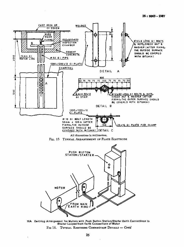
IS t 3043 - 1987
CAST IRON OR
<P 10 Gl BOLT LENGTH SOmm a 100 m (AFTER FIXING,THE OUTSIDE SURFACE SHOULD BE COVERED WITH BITUMIN)
25x10. Gl PLATE FOR CLAMP
DETAIL C All dimensions in millimetres.
FIG. 15 TYPICAL ARRANGEMENT OF PLATE ELECTRODE
PUSH BUTTON STATION/STARTER-
16A Earthing Arrangement for Motors with Push Button Station/Starter Earth Connections to Starter Looped from Earth Connections of Motor
FIG 16. TYPICAL EARTHING CONNECTION DETAILS — Contd
25
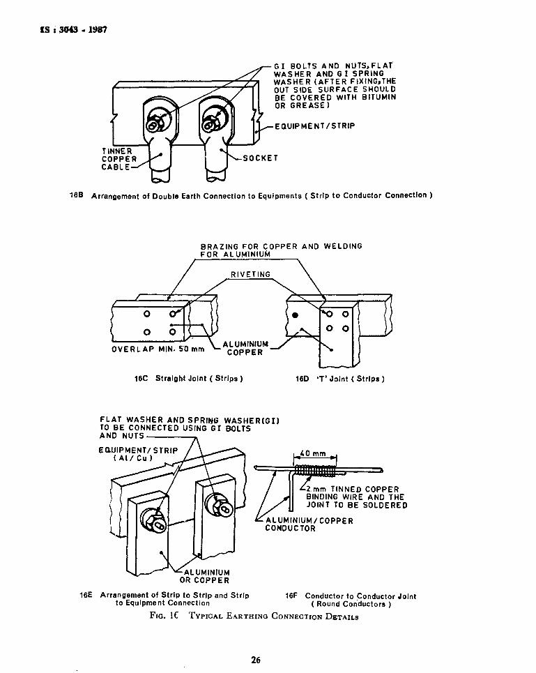
IS i 3043 - 1987
^r G I BOLTS AND NUTS,FLAT WASHER AND G I SPRING WASHER (AFTER FIXINGjTHE OUT SIDE SURFACE SHOULD BE COVERED WITH BITUMIN OR GREASE)
EQUIPMENT/STRIP
TINNER COPPER CABLE
SOCKET
16B Arrangement of Double Earth Connection to Equipments ( Strip to Conductor Connection )
BRAZING FOR COPPER AND WELDING FOR ALUMINIUM
OVERLAP MIN. 50 mm * - COPPER
16C Straight Joint ( Strips )
A L U M I N I U M ^ / v ^
16D 'T'Joint ( Strips )
FLAT WASHER AND SPRING WASHER(GI ) TO BE CONNECTED USING G I BOLTS AND NUTS
EO.UIPMENT/ STRIP ( A l / C u )
-ALUMINIUM OR COPPER
JiO mm
-2 mm TINNED COPPER BINDING WIRE AND THE JOINT TO BE SOLDERED
ALUMINIUM/COPPER CONDUCTOR
16E Arrangement of Strip to Strip and Strip to Equipment Connection
16F Conductor to Conductor Joint ( Round Conductors )
FIG. 1C TYPICAL EARTHINO CONNECTION DETAILS
26
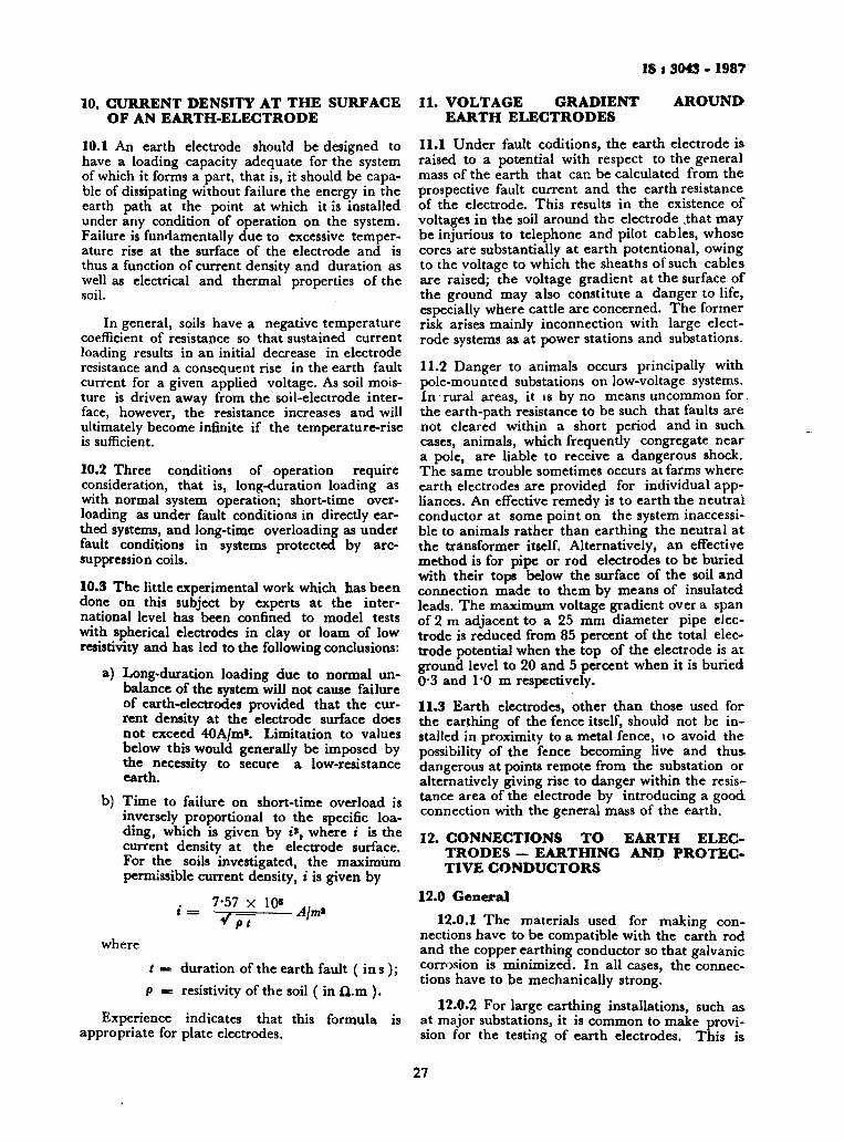
IS i 3043 - 1987
10. CURRENT DENSITY AT THE SURFACE OF AN EARTH-ELECTRODE
10.1 An earth electrode should be designed to have a loading capacity adequate for the system of which it forms a part, that is, it should be capable of dissipating without failure the energy in the earth path at the point at which it is installed under any condition of operation on the system. Failure is fundamentally due to excessive temperature rise at the surface of the electrode and is thus a function of current density and duration as well as electrical and thermal properties of the soil.
In general, soils have a negative temperature coefficient of resistance so that sustained current loading results in an initial decrease in electrode resistance and a consequent rise in the earth fault current for a given applied voltage. As soil moisture is driven away from the soil-electrode interface, however, the resistance increases and will ultimately become infinite if the temperature-rise is sufficient.
10.2 Three conditions of operation require consideration, that is, long-duration loading as with normal system operation; short-time overloading as under fault conditions in directly earthed systems, and long-time overloading as under fault conditions in systems protected by arc-suppression coils.
10.3 The little experimental work which has been done on this subject by experts at the international level has been confined to model tests with spherical electrodes in clay or loam of low resistivity and has led to the following conclusions:
a) Long-duration loading due to normal unbalance of the system will not cause failure of earth-electrodes provided that the current density at the electrode surface does not exceed 40A/m*. Limitation to values below this would generally be imposed by the necessity to secure a low-resistance earth.
b) Time to failure on short-time overload is inversely proportional to the specific loading, which is given by »», where i is the current density at the electrode surface. For the soils investigated, the maximum permissible current density, i is given by
7-57 x 10" .. . • - ~VJT A'm
where
t — duration of the earth fault ( i n s ); P = resistivity of the soil ( i n fl.m ).
Experience indicates that this formula is appropriate for plate electrodes.
11. VOLTAGE GRADIENT AROUND EARTH ELECTRODES
11.1 Under fault coditions, the earth electrode is raised to a potential with respect to the general mass of the earth that can be calculated from the prospective fault current and the earth resistance of the electrode. This results in the existence of voltages in the soil around the electrode .that may be injurious to telephone and pilot cables, whose cores are substantially at earth potentional, owing to the voltage to which the sheaths of such cables are raised; the voltage gradient at the surface of the ground may also constitute a danger to life, especially where cattle are concerned. The former risk arises mainly inconnection with large electrode systems as at power stations and substations.
11.2 Danger to animals occurs principally with pole-mounted substations on low-voltage systems. In rural areas, it is by no means uncommon for the earth-path resistance to be such that faults are not cleared within a short period and in such cases, animals, which frequently congregate near a pole, are liable to receive a dangerous shock. The same trouble sometimes occurs at farms where earth electrodes are provided for individual appliances. An effective remedy is to earth the neutrai conductor at some point on the system inaccessible to animals rather than earthing the neutral at the transformer itself. Alternatively, an effective method is for pipe or rod electrodes to be buried with their tops below the surface of the soil and connection made to them by means of insulated leads. The maximum voltage gradient over a span of 2 m adjacent to a 25 mm diameter pipe electrode is reduced from 85 percent of the total electrode potential when the top of the electrode is at ground level to 20 and 5 percent when it is buried 0"3 and 1*0 m respectively.
11.3 Earth electrodes, other than those used for the earthing of the fence itself, should not be installed in proximity to a metal fence, 10 avoid the possibility of the fence becoming live and thus. dangerous at points remote from the substation or alternatively giving rise to danger within the resistance area of the electrode by introducing a good-connection with the general mass of the earth.
12. CONNECTIONS TO EARTH ELECTRODES — EARTHING AND PROTECTIVE CONDUCTORS
12.0 General 12.0.1 The materials used for making con
nections have to be compatible with the earth rod and the copper earthing conductor so that galvanic corrosion is minimized. In all cases, the connections have to be mechanically strong.
12.0.2 For large earthing installations, such as at major substations, it is common to make provision for the testing of earth electrodes. This is
27
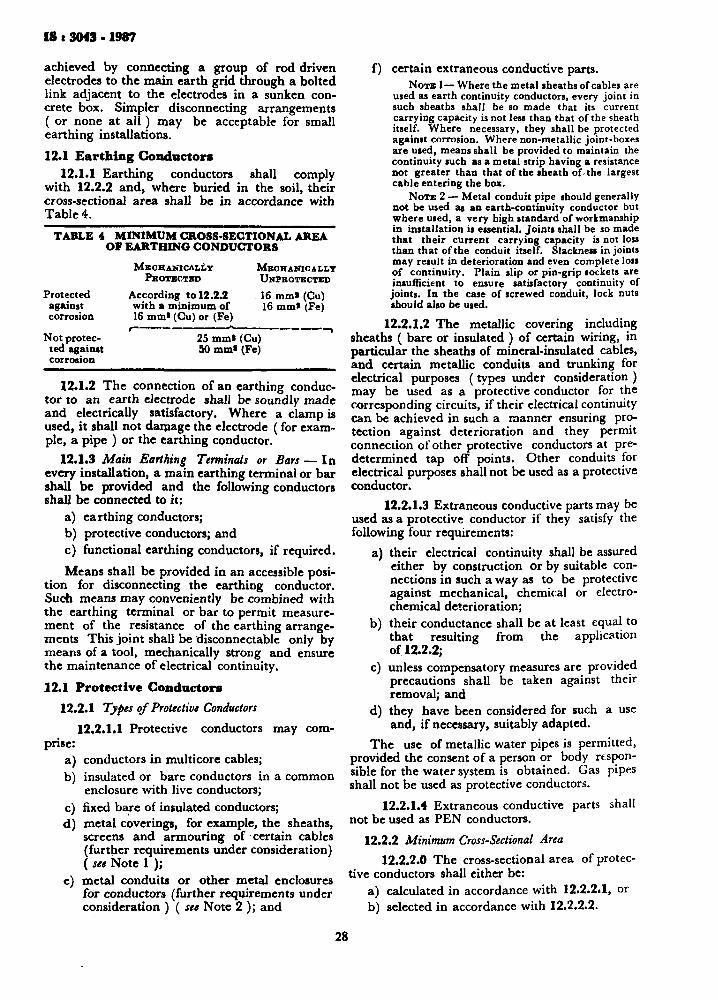
IS t 3043 . 1987
achieved by connecting a group of rod driven electrodes to the main earth grid through a bolted link adjacent to the electrodes in a sunken concrete box. Simpler disconnecting arrangements ( or none at a l l ) may be acceptable for small earthing installations. 12.1 Earthing Conductors
12.1.1 Earthing conductors shall comply with 12.2.2 and, where buried in the soil, their cross-sectional area shall be in accordance with Table 4.
TABLE 4 (
Protected against corrosion
Not protected against corrosion
MINIMUM CROSS-SECTIONAL AREA OF EARTHING CONDUCTORS
MECHANICALLY MECHANICALLY PBOTECTED UNPROTECTED
According to 12.2.2 16 mm* (Cu) with a minimum of 16 mm* (Fe) 16 mm* (Cu) or (Fe)
25 mm* (Cu) 50 mm* (Fe)
12.1.2 The connection of an earthing conductor to an earth electrode shall be soundly made and electrically satisfactory. Where a clamp is used, it shall not damage the electrode (for example, a pipe ) or the earthing conductor.
12.1.3 Main Earthing Terminals or Bars — In every installation, a main earthing terminal or bar shall be provided and the following conductors shall be connected to it:
a) earthing conductors; b) protective conductors; and c) functional earthing conductors, if required. Means shall be provided in an accessible posi
tion for disconnecting the earthing conductor. Such means may conveniently be combined with the earthing terminal or bar to permit measurement of the resistance of the earthing arrangements This joint shall be disconnectable only by means of a tool, mechanically strong and ensure the maintenance of electrical continuity.
12.1 Protective Conductors 12.2.1 Types of Protective Conductors
12.2.1.1 Protective conductors may comprise:
a) conductors in multicore cables; b) insulated or bare conductors in a common
enclosure with live conductors; c) fixed bare of insulated conductors; d) metal coverings, for example, the sheaths,
screens and armouring of certain cables (further requirements under consideration) ( see Note 1 );
e) metal conduits or other metal enclosures for conductors (further requirements under consideration ) ( see Note 2 ); and
f) certain extraneous conductive parts. NOTE 1— Where the metal sheaths of cables are
used as earth continuity conductors, every joint in such sheaths shall be so made that its current carrying capacity is not less than that of the sheath itself. Where necessary, they shall be protected against corrosion. Where non-metallic joint-boxes are used, means shall be provided to maintain the continuity such as a metal strip having a resistance not greater than that of the sheath of the largest cable entering the box.
NOTE 2 — Metal conduit pipe should generally not be used as an earth-continuity conductor but where used, a very high standard of workmanship in installation is essential. Joints shall be so made that their current carrying capacity is not loss than that of the conduit itself. Slackness in joints may result in deterioration and even complete loss of continuity. Plain slip or pin-grip sockets are insufficient to ensure satisfactory continuity of joints. In the case of screwed conduit, lock nuts should also be used.
12.2.1.2 The metallic covering including sheaths ( bare or insulated ) of certain wiring, in particular the sheaths of mineral-insulated cables, and certain metallic conduits and trunking for electrical purposes (types under consideration ) may be used as a protective conductor for the corresponding circuits, if their electrical continuity can be achieved in such a manner ensuring protection against deterioration and they permit connection of other protective conductors at predetermined tap off points. Other conduits for electrical purposes shall not be used as a protective conductor.
12.2.1.3 Extraneous conductive parts may be used as a protective conductor if they satisfy the following four requirements:
a) their electrical continuity shall be assured either by construction or by suitable connections in such a way as to be protective against mechanical, chemical or electrochemical deterioration;
b) their conductance shall be at least equal to that resulting from the application of 12.2.2;
c) unless compensatory measures are provided precautions shall be taken against their removal; and
d) they have been considered for such a use and, if necessary, suitably adapted.
The use of metallic water pipes is permitted, provided the consent of a person or body responsible for the water system is obtained. Gas pipes shall not be used as protective conductors.
12.2.1.4 Extraneous conductive parts shall not be used as PEN conductors.
12.2.2 Minimum Cross-Sectional Area 12.2.2.0 The cross-sectional area of protec
tive conductors shall either be: a) calculated in accordance with 12.2.2.1, or b) selected in accordance with 12.2.2.2.
28

IS t 3043 - 1987
In both cases, 12.2.2.3 shall be taken into account.
NOTE — The installation should be so prepared that equipment terminals are capable of accepting these protective conductors.
12.2.2.1 The cross-sectional area shall be so calculated that the current density value determined by the following formula is not exceeded ( applicable only for disconnection times not exceeding 5 s ) .
1 - j t - L -where
S = cross-sectional area, in square millimetres;
/ = value ( ac, rms ) of fault current for a fault of negligible-impedance, which can flow through the protective device, in amperes;
t = operating time of the disconnecting device, in seconds; and
NOTE — Account should be taken of the current-limiting effect of the circuit impedances and the limiting capability (joule integral) of the protective device.
k = factor dependent on the material of the protective conductor, the insulation and other parts, and the initial and final temperatures. Values of k for protective conductors in various use or service for t =» 1 and 3 s respectively are given in Table 6A to 6D.
230
The k factors for protective conductors of copper, steel and aluminium are shown in Fig. 17 to 19.
If application of the formula produces non-standard sizes, conductors of the nearest higher standard cross-sectional area shall be used.
NOTE 1 — It is necessary that the cross-sectional area so calculated be compatible with the conditions imposed by fault loop impedance.
NOTE 2 — Maximum permissible temperatures for joints should be taken into account.
NOTE 3 — Values for mineral'insulated cables are under consideration.
Method of deriving the factor k The factor k is determined from the formula:
where Q.0 = volumetric heat capacity of conduc
tor material (j/°C mm8 ), B = reciprocal of temperature coefficient
of resistivity at 0°C for the conductor ( ° C ) ,
Sj0 — electrical resistivity of couductor material at 20°C ( Q-mm ),
6i = initial temperature of conductor ( °C ), and
6t = final temperature of conductor (°C). These material constants are given in Table 5.
100 200 300 FINAL TEMPERATURE *C
400 508
Fro. 17 k FACTORS FOR COPPER PROTECTIVE CONDUCTORS ( See 12.2.2.1 )
29
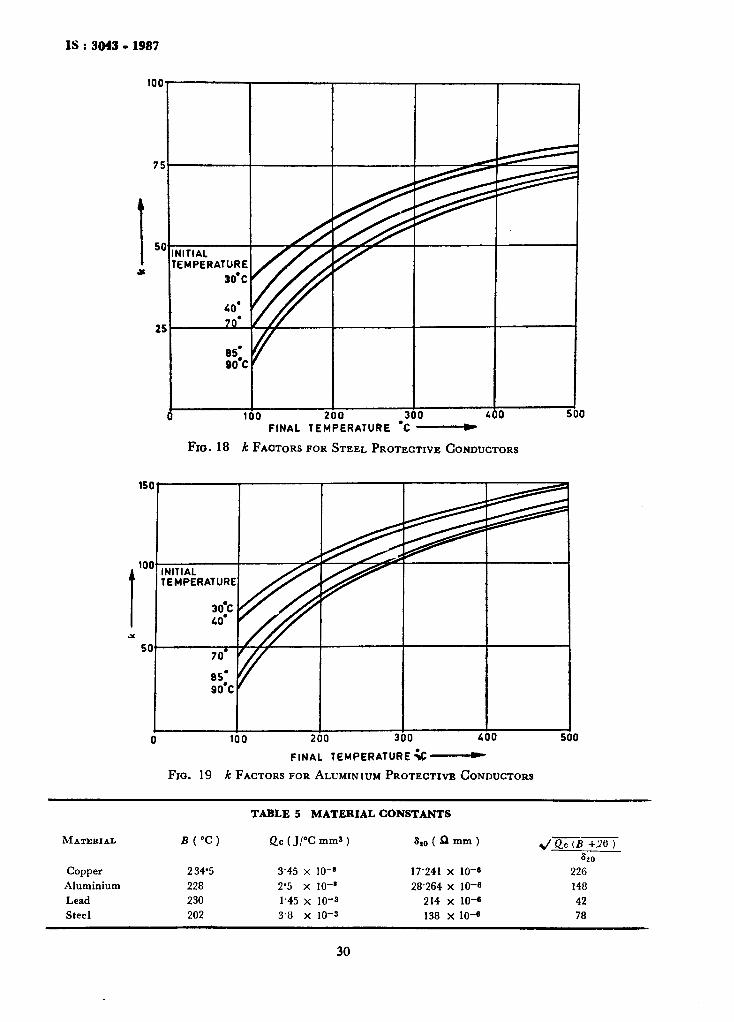
IS : 3043 • 1987
100 200 FINAL TEMPERATURE
500
Fro. 18 k FACTORS FOR STEEL PROTECTIVE CONDUCTORS
100 «00 500
M A T E R I A L
Copper Aluminium Lead Steel
FlO. 19
B ( ° C )
234-5 228 230 202
FINAL TEMPERA k FACTORS FOR ALUMINIUM PROTECTIVE CONDUCTORS
TABLE 5 MATERIAL CONSTANTS
(MjrCmmS)
3-45 x 10- ' 2-5 x 10-* 1-45 x 10-3 3-a x 10-3
5,0 ( U mm )
17-241 x 10~« 28264 X 10-«
214 x 10-« 138 X 10-«
y/ fie (£ +.26 ) 820
226 148 42 78
30
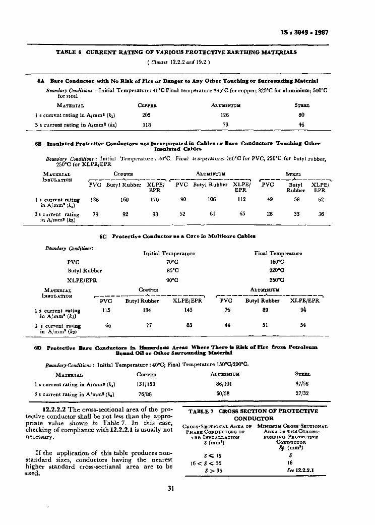
IS < 3043 - 1987
TABLE 6 CURRENT RATING OF VARIOUS PROTECTIVE EARTHING MATERIALS
{Clauses 12.2.2and 19.2 )
6A Bare Conductor with N o Risk of Fire or Danger to Any Other Touching or Surrounding Material
Boundary Conditions : Initial Ttmperatvre : 40°C Final temperature 395CC for copper; 325°C for aluminium; 500CC for steel
M A T E R I A L COPPER
1 s current rating in A/mm* (k{) 205
3 s current rating in A/mm 2 (As) 118
ALUMINIUM
126
73
STEEL
80
46
6B Insulated Protective Conductors not Incorporated in Cables or Bare Conductors Touching Other Insulated Cables
Boundary Conditions: Initial Temperature : 40°C. Fical Umperature: 160CC for PVC, 220°C for butyl rubber, 250°C for XLPE/EPR
M A T E R I A L INSULATION
1 s current rating in A/mm* (k,)
C O P P E R A L U M I M U M STEEL
PVC Butyl Rubber XLPE/ PVC Butyl Rubber XLPE/ PVC Butyl XLPE/ EPR EPR Rubber EPR
136
3 s current rating 79 in A/mm* (ts)
160
92
170
98
90
52
106
61
112
65
49
28
58
33
62
36
6C Protect ive Conductor as a Core in Multicore Cables
Boundary Conditions:
PVC Butyl Rubber
XLPE/EPR
M A T E R I A L INSULATION
1 s current rating in A/mm* (ki)
3 s current rating in A/mm* (A3)
' "PVC 115
66
Init ial Temperature
C O P P E R
Butyl Rubher
134
77
70°C 85"C
90°C
XLPE/EPR"1
143
83
PVC
76
44
Final Tempe 160°C 220°C
250°C
ALUMINIUM
Butyl Rubber
89
51
rature
XLPE/EPR
94
54
6D Protect ive Bare Conductors in Hazardous Areas Where There is Risk o f Fire f r o m Petro leum Bound Oil or Other Surrounding Material
Boundary Conditions : Initial Temperature : 40°C; Final Temperature 150°C/200oC.
M A T E R I A L C O P P E R ALUMINIUM
1 J current rating in A/mm* (kj) 131/153 86/101
3 s current rating in A/mm* (*,) 76/88 50/58
STEEL
47/56
27/32
12.2.2.2 The cross-sectional area of the protective conductor shall be not less than the appropriate value shown in Table 7. In this case, checking of compliance with 12.2.2.1 is usually not necessary.
If the application of this table produces non-standard sizes, conductors having the nearest higher standard crOss-sectianal area are to be used.
TABLE 7 CROSS SECTION OF PROTECTIVE CONDUCTOR
CROSS-SECTIONAL A R E A OF MINIMUM CROSS-SECTIONAL P H A S E CONDUCTORS OP
THE INSTALLATION S (mm1)
S< 16 16 < S < 35
5 > 3 5
A R E A OP T H E CORRESPONDING PROTECTIVE
CONDUCTOR Sp (mm*)
S 16 Set 12.2.2.1
31
IS i 3043 • 1987
The values in Table 7 are valid only if the protective conductor is made of the same metal as the phase conductors. If this is not so, the cross-sectional area of the protective conductor is to be determined in a manner which produces a conductance equivalent to that which results from the application of Table 7 ( see also 18.3.3 ).
12.2.2.3 The cross-sectional area of every protective conductor which does not form part of the supply cable or cable enclosure shall be, in any case, not less than:
a) 2-5 m m ' , if mechanical protection is provided; and
b) 4 mm*, if mechanical protection is not provided.
12.2.3 Preservation of Electrical Continuity of Protective Conductors
12.2.3.1 Protective conductors shall be suitably protected against mechanical and chemical deterioration and electrodynamic forces.
12.2.3.2 Joints of protective conductors shall be accessible for inspection and testing except in compound-filled or encapsulated joints .
12.2.3.3 No switching device shall be inserted in the protective conductor, but joints which can be disconnected for test purposes by use of a tool may be provided.
12.2.3.4 Where electrical monitoring of earth-continuity is used, the operating coils shall not be inserted in protective conductors.
12.2.3.5 Exposed conductive parts of apparatus shall not be used to form part of the protective conductor for other equipment except as allowed by the preconditions in 12.2.1.2.
13. EARTHING ARRANGEMENTS FOR PROTECTIVE PURPOSES
NOTE — For protective measures for various systems of earthing, see Section 3.
13.1 Protec t ive Conductors u s e d w i t h O v e r -current Protect ive D e v i c e s
13.1.1 When overcurrent protective devices are used for protection against electric shock, the incorporation of the protective conductor in the same wiring system as the live conductors or in their immediate proximitv is strongly recommended.
13.2 Earth ing and Protec t ive Conductors for Fault -Voltage-Operated Protec t ive Dev ice s
13.2.1 An auxiliary earth electrode shall be provided electrically - independent of all other earthed metal, for example, constructional metal-work, pipers, or metal-sheathed cables. This requirement is considered to be fulfilled if the
auxiliary earth electrode is installed at a specified distance from all other earthed metal ( value of distance under consideration ).
13.2.2 T h e earthing conductor leading to the auxiliary earth electrode shall be insula ted to avoid contact with the protective conductor or any of the parts connected thereto or ex t raneous conductive parts which are, or may be, in contac t with them.
NOTE — This requirement is necessary to prevent the voltage-sensitive element being inadvertently bridged.
13.2.3 T h e protective conductor shalj be connected only to the exposed conductive parts of those items of electrical equipment whose supply will be interrupted in the event of the protective device operating under fault conditions.
13.2.4 Excessive Earthed-leakage Current — U n d e r consideration.
14. EARTHING ARRANGEMENTS FOR FUNCTIONAL PURPOSES
14.1 General —Earthing arrangements for functional purposes shall be provided to ensure correct operation of equipment or to permit reliable a n d proper functioning of installations.
( Further requirements under consideration ).
14.2 Low N o i s e — See 39.22.
15. EARTHING ARRANGEMENTS FOR COMBINED PROTECTIVE AND FUNCTIONAL PURPOSES
15.1 Genera l — Where earthing for combined protective and functional purposes is required, the requirements for protective measures shall prevail.
15.2 P E N Conductors
15.2.1 I n T N systems, for cables in fixed installations having a cross-sectional area not less than 10 mm* for copper and 16 mm* for- aluminium, a single conductor may serve both as protective conductor and neutral conductor, provided that the part of the installation concerned is not protected by a residual current-operated device.
However, the minimum cross-sectional area of a PEN conductor may be 4 mm 1 , provided t h a t the cable is of a concentric type conforming t o Indian Standards and tha t duplicate continuity connections exist at all joints and terminations in the run of the concentric conductors.
15.2.2 T h e PEN conductor shall be insulated for the highest voltage to which it may be subjected to avoid stray currents.
NOTE — The PEN conductor need not be insulated inside switchgear and controlgear assemblies.
32

IS i 3043 • 1987
15.2.3 If from any point of the installation the neutral and protective functions are provided by separate conductors, it is inadmissible to connect these conductors to each other from that point. At the point of separation, separate terminals or bars shall be provided for the protective and neutral conductors. The PEN conductor shall be connected to the terminal or bare intended for the protective conductor.
16. EQUIPOTENTIAL BONDING CONDUCTORS
16.1 Minimum Cross-Sectional Areas
16.1.1 Equipotential See 12.2.2.1.
Bonding Conductors —
16.1.2 Bonding of Water Meters — Bonding of water meters is not permitted ( see 9.2.4 ).
16.2 Non-Earthed Equipotential Bonding — Under consideration.
17. TYPICAL SCHEMATIC OF EARTHING AND PROTECTIVE CONDUCTORS
17.1 A typical schematic of earthing and protective conductors is given in Fig. 20.
EE ^ 3
W?7? V/////////////////Z7X
LED
INSTALLATION EARTHING
[ 35
EJ::
II v;;j;;;/s;;j////s;;;;j;;;y.
/ EE
-E CQUfPMFNT EE E E EQUIPMENT EARTHING
Af «» Exposed conductive parts P =• Incoming metallic service C —■ Extraneous conductive parts
EE — Earth electrode 1 — Equipotential bonding conductor ( in case of small domestic installations 1 takes the form
of neutral link ) 2 = Protective conductor ( in duplicate ) 3 = Earthing conductor
Fio. 20 EARTHING ARRANGEMENTS AND PROTECTIVE CONDUCTOR
33
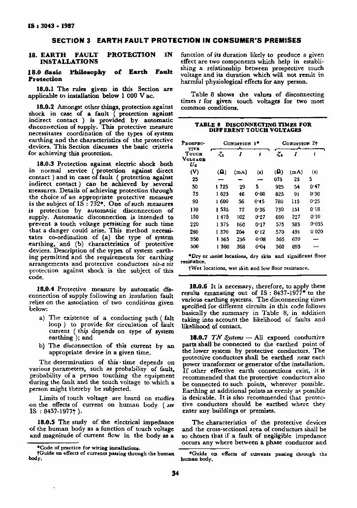
IS t 3043 - 1987
SECTION 3 EARTH FAULT PROTECTION IN CONSUMER'S PREMISES
18. EARTH FAULT PROTECTION IN INSTALLATIONS
18.0 Basic Philosophy of Earth Fault Protection
18.0.1 The rules given in this Section are applicable to installation below 1 000 V ac.
18.0.2 Amongst other things, protection against shock in case of a fault ( protection against indirect contact ) is provided by automatic disconnection of supply. This protective measure necessitates coordination of the types of system earthing and the characteristics of the protective devices. This Section discusses the basic criteria for achieving this protection.
18.0.3 Protection against electric shock both in normal service (protection against direct contact ) and in case of fault ( protection against indirect contact) can be achieved by several measures. Details of achieving protection through the choice of an appropriate protective measure is the subject of IS : 732*. One of such measures is protection by automatic disconnection of supply. Automatic disconnection is intended to prevent a touch voltage persisting for such time that a danger could arise. This method necessitates co-ordination of (a) the type of system earthing, and (b) characteristics of protective devices. Description of the types of system earthing permitted and the requirements for earthing arrangements and protective conductors vis-avis protection against shock is the subject of this code.
18.0.4 Protective measure by automatic disconnection of supply following an insulation fault relies on the association of two conditions given below:
a) The existence of a conducting path ( fait loop ) to provide for circulation of fault current ( this depends on type of system earthing ); and
b) The disconnection of this current by an appropriate device in a given time,
The determination of this • time depends on various parameters, such as probability of fault, probability of a person touching the equipment during the fault and the touch voltage to which a person might thereby be subjected.
Limits of touch voltage are based on studies on the effects of current on human body (see IS : 8437-1977t )•
18.0.5 The study of the electrical impedance of the human body as a function of touch voltage and magnitude of current flow in the body as a
•Code of practice for wiring installations. tGuide on effects of currents passing through the human
body.
function of its duration likely to produce a given effect are two components which help in establishing a relationship between prospective touch voltage and its duration which will not result in harmful physiological effects for any person.
Table 8 shows the values of disconnecting times t for given touch voltages for two most common conditions.
18.0.6 It is necessary, therefore, to apply these results emanating out of IS : 8437-1977* to the various earthing systems. The disconnecting times specified for different circuits in this code follows basically the summary in Table 8, in addition taking into account the likelihood of faults and likelihood of contact.
18.0.7 TN SysUms — All exposed conductive parts shall be connected to the earthed point of the lower system by protective conductors. The protective conductors shall be earthed near each power transformer or generator of the installation. If other effective earth connections exist, it is recommended that the protective conductors also be connected to such points, wherever possible. Earthing at additional points as evenly as possible is desirable. It is also recommended that protective conductors should be earthed where they enter any buildings or premises.
The characteristics of the protective devices and the cross-sectional area of conductors shall be so chosen that if a fault of negligible impedance occurs any where between a phase conductor and
•Guide on effects of currents passing through the human body.
TABLE 8 DISCONNECTING TIMES FOR DIFFERENT TOUCH VOLTAGES
PB08PBC-
TOUCH VoLTAOB
(V) 25 50 75 90
no 150 220 280 350 500
♦Dry or
CONDITION 1*
Zx
(O)
1725 1625 1 600 1 535 1475 1375 1 370 1 365 1 360
H
29 46 56 72
102 160 204 256 368
moist locations,
t
w 5 0-60 0-45 0-36 0-27 0-17 0M2 0-08 0*04
dry skin
CONDITIO , * _ Zx I
(A) (mA) 075 23 925 825 780 730 660 575 570 565 560
and
54 91
115 151 227 383 491 620 893
m 2f
t
(•) 5 0-47 030 0-25 0 18 o-io 0-035 0 020 — —
significant floo: resistance.
fWet locations, wet skin and low floor resistance.
34

IS t 3043 - 1987
a protective conductor or exposed conductive part, automatic disconnection of the supply will occur within the minimum possible safe time. The time of operation would depend on the magnitude of the contact potential. As a general rule, 65 V may be cleared within 10 seconds and voltages of the order of 240 V and above shall be cleared instantaneously.
This requirement is met if: Zn X 7a < U0
where Zt ■= fault loop impedance, /» = current ensuring the automatic
operation of disconnecting device, and
U0 — conventional voltage limits. NOTE \ — Zt may be calculated or measured. NOTE 2 — The duration of It, permitted depends
on the prospective touch voltage. The touch voltage is calculated from the voltage of the system and the ratio of the impedance of the source and the fault loop. Higher touch voltages should be cleared in shorter times. If this condition cannot be fulfilled, supple
mentary bonding in accordance with 18.0.10 may be necessary.
18.0.8 TT Systems — All exposed conductive parts collectively protected by the same protective device shall be interconnected by protective conductors with an earth electrode common to all those parts. Where several protective devices are used in series, this requirement applies separately to all the exposed conductive parts protected by each device. For compliance with the requirement of 18.0.7 ( para 2 ), the following shall be fulfilled:
* A X / . < Ue
where R± = resistance of the earthed system for
exposed conductive parts, / a = operating currents of the disconne
cting series device or settings of shunt relays, and
U0 = conventional voltage limit ( 32 V in case of relays with time lag ) .
18.0.9 IT Systems — The impedance of the power system earth shall be such that on the occurrence of a single fault to exposed conductive parts or to earth, the fault current is of low value. Disconnection of the supply is not essential on the occurrence of the first fault. Protective measures must, however, prevent danger on the occurrence of two simultaneous faults involving different live conductors.
The following condition shall be fulfilled:
*A X It < U0
where RA = resistance of the earthed system for
exposed conductive parts, Ia = operating currents of the disconne
cting series device, and Ue = conventional voltage limit.
18.0.10 Equipotential Bonding — If the conditions specified in 18.0.7 to 18.0.9 cannot be fulfilled for automatic disconnection ot supply, it is necessary to provide local equipotential bonding { see also 18.3.4 ). This applies to entire installation or a part thereof, an item of apparatus or a location. The protective conductors for local bonding shall also conform to 12.2. Where doubt exists regarding effectiveness of supplementary equipotential bonding, it shall be confirmed if:
'a where
Z = impedance between simultaneously accessible exposed conductive parts and extraneous conductive parts, and earthing system;
Ja = operating current of the disconnecting series device; and
U = conventional voltage limit.
18.1 Basic Purpose of E a r t h Fau l t P ro tec t ion — The occurrence of an earth fault in an installation creates two possible hazards. Firstly, voltages appear between exposed conductive parts and extraneous conductive parts, and if these parts are simultaneously accessible, these voltages constitute a shock hazard, this condition being known as indirect contact.
Secondly, the fault current that flows in the phase and protective conductors of the circuit feeding the faulty equipment ( the earth fault may, of course, occur in the fixed wiring of the circuit itself ) may be of such a magnitude as to cause an excessive temperature rise in those conductors, thereby creating a fire hazard.
The protective measure known as 'earthed equipotential bonding and automatic disconnection of the supply' is intended to give a high degree of protection against both hazards. The choice of protective device used to give disconnection is influenced by the type of system of which the installation is part, because either:
a) the earth fault loop impedance has to be low enough to allow adequate earth fault current to low to cause an overcurrent protective device ( for example, a fuse or circuit breaker) in the faulty circuit to operate in a sufficiently short time; or
b) where it is not possible to achieve a low enough earth fault loop impedance, disconnection may be initiated by fitting either
35
IS : 3043 - 1987
a residual current device or a voltage operated earth leakage circuit breaker with the former being preferred.
18.2 Earthing of Installations
18.2.1 Protection Against Indirect Contact ( Against Electric Shock in Case of a Fault) — Protection against indirect contact is achieved by the adoption of one of the following protective measures:
a) Safety extra low voltage; b) The use of Glass II equipment or by equi
valent insulation; c) A non-conducting location; d) Earth free local equipotential bonding; e) Electrical separation; and f) Earthed equipotential bonding and auto
matic disconnection of the supply. NOTB 1 — The primary concern of this Code is (d)
and (f) while other methods of protection against indirect contact are covered in other relevant Indian Standard Codes of Practice.
NOTE 2 — Item (a) requires that the nominal voltage of the circuit concerned does not exceed extra low voltage that tire source has a high degree of isolation from higher voltage circuits ( for example, a Class II safety isolation transformer ) and that live parts also have a similar degree of isolation or separation from those circuits. The most important requirement, however, is that live parts and exposed conductive parts of a safety extra low voltage circuit should not be connected to earth, protective conductors or exposed conductive parts of another circuit. Where these general requirements are not met but the nominal voltage still does not exceed extra low voltage, the circuit is described as a functional extra low voltage circuit and one part of it may be connected to earth.
N O T E 3 — Item (b) is generally applicable and covers the selection and use of equipment complying
W i t h either insulation encased Class II equipment ( 'all-insulated' ) or metal cased Class II equipment. In some cases, such as factory built assemblies of switchgear and controlgear, the equivalent term used is 'total insulation'. Item (b) can also be achieved by the application of suitable supplementary or reinforced insulation to equipment on site.
Earthing of the equipment is not required; in fact, by definition there will be no facility for earthing provided in Class II equipment.
NOTB 4 — Items (c), (d) and (e) are of limited interest as they can be applied only in special situations and used under effective supervision. They all include a high degree of isolation from earth.
None 5 — In this Section, detailed consideration is limited to earthed equipotential bonding and automatic disconnection of the supply.
1 8 . 2 . 2 Earthed Equipotential Bonding and Automatic Disconnection of the Supply — T h e t w o a ims of this pro tec t ive measure are to:
a) ensure that w h e n a n earth fault occurs, t h e vo l tages appear ing b e t w e e n exposed c o n duct ive parts a n d extraneous conduct ive parts in the locat ion served by the installat ion c o n c e r n e d are min imized; a n d
b) ensure rapid d i s connec t ion o f the circuit in w h i c h that earth fault occurs.
In order to meet (a), a zone is created by first connecting all extraneous conductive parts by means of equipotential bonding conductors to the main earthing terminal or earth electrode (s) of the installation.
The zone is completed by the connection of all exposed conductive parts of the circuits in the installation and of current-using equipment fed from those circuits to the main earthing terminal ( or installation earth electrode ) using circuit protective conductors.
Whilst such a zone is called an equipotential zone, this does not mean that voltages cannot exist between conductive parts in that zone when an earth fault occurs. The voltages referred to earlier ( see 18.1 ) will still exist between the exposed conductive parts of perfecdy sound equipment and between such parts and extraneous conductive parts, but the application of bonding minimizes these voltages in each case.
An installation may consist of a number of zones; for instance, when an installation supplies a number of buildings, equipotential bonding is necessary in each building so that each constitutes a zone having a reference point to which the exposed conductive parts of the circuits and current-using equipment in that building are connected.
The second aim of this protective measure is met by limiting the upper value of the earth fault loop impedance of each circuit to a value determined by the type and current rating of the protective device concerned such that, on the occurrence of an earth fault ( assumed to be of negligible impedance ), disconnection will occur before the prospective touch voltage reaches a harmful value.
18.2.3 Extraneous Conductive Parts — The extraneous conductive parts that are required to be bonded to the main earthing terminal of the installation ( or to the earth electrode of the installation ) include:
a gas pipes; b) other service pipes and ducting; c) risers and pipe? of fire protection equip
ment; d) exposed metallic parts of the building
structure; and e) lightening conductors ( see Section 8 ).
NOTB — Connections to pipes, ducting and exposed metallic parts of building structure should be considered most carefully. In some types of earthing systems, especially TN-C or TN-C-S systems effectively connect extraneous conducting metalwork to the supply system neutral and could cause continuously circulating currents and standing voltages that might result in electrochemical corrosion or random spark hazards in potentially flammable atmospheres.
36

IS i 3043 - 1987
18.2.4 Exposed Conductive Parts — Exposed conductive parts that are required to be connected by means of protective conductors to the main earthing terminal ( or earth flectrode ) of the installation are as follows:
a) All metalwork associated with wiring system ( other than current-carrying parts ) including cable sheaths and armour, conduit, ducting, trunking, boxes and catenary wires;
b) The exposed metalwork of all Glass I fixed and portable current-using equipment. Even where at the time of the erection of the installation this equipment is of Class II construction or its equivalent, because there is a possibility that in the life of the installation the equipment may be replaced by Class I equipment, all fixed wiring accessories should incorporate an earthing terminal that is connected to the main earthing terminal by means of the protective conductors of the circuits concerned.
c) The exposed metalwork of transformers used in the installation other than those that are an integral part ol equipment. The secondary windings of transformers should also be earthed at one point of the winding, unless the transformer is a safety isolating transformer supplying a part of the installation where the protective measure 'electrical separation' is being used).
Exposed conductive parts that ( because of their small dimensions or disposition ) cannot be gripped or contacted by a major surface of the human body ( that is, a human body surface not exceeding 50 mm x 50 mm) need not be earthed if the connection of those parts to a protective conductor cannot readily be made and reliably maintained. Typical examples of such parts are screws and nameplate, cable clips and lamp caps. Fixing screws for non-metallic accessories need not be earthed provided there is no appreciable risk of the screws coming into contact with live parts.
Other exposed conductive parts not required to be earthed are:
1) Overhead line insulator brackets and metal parts connected to them if such parts are not within arm's reach; and
2) Short lengths of metal conduit or other metal enclosures used to give mechanical protection to equipment of Class II or equivalent cunstruction.
18. Protection against Excessive Temperature Rise and Mechanical Damage
18.3.1 General — The protective circuit of an installation includes the following ( see Fig. 20 ):
a) Circuit protective conductors;
b) Equipotential bonding conductors; and c) Earthing conductors.
Under certain circumstances, there may also be local equipotential bonding conductors.
The determination of cross-sectional areas of all these conductors is the subject of Section 2 ( also see 18.4 ) and here consideration is limited to the types of conductor that can be used with some indication of the precautions that should be taken during erection, particularly those concerned with mechanical and chemical deterioration and electro-dynamic effects.
18.3.2 Earthing Conductors — Copper earthing conductors, in general, need not be protected against corrosion when they are buried in the ground if their cross-sectional area is equal to or greater than 25 mm*. In case of buried steel conductors, appropriate corrosion factors based upon the summed up corrosion indexes corresponding to different parameters connected with the material for grounding, environmental conditions, nature of soil, etc ( see Section 4 ) should be applied in determining the size of the earthing conductor, however, the minimum size should not be less than 50 mm*. If the earthing conductor is of tape or strip, the thickness should be adequate to withstand mechanical damage and corrosion.
It should be remembered that plain uncoated copper is positive to plain uncoated buried steel and when interconnected by a current carrying conductor, these metals will form an electrochemical cell that can cause accelerated corrosion of steel. As a rough guide, a dc current of 1 A leaving a buried steel structure can remove nearly 9 kg of metal in one year.
Where such conductors are protected against corrossion but are not mechanically protected, the minimum cross-sectional area is 16 mm* if the conductor is of copper or coated steel ( Table 4 ) . The determination of the cross-sectional area where the earthing conductor is both mechanically protected and protected against corrosion is considered in a later section.
Aluminium or copper clad aluminium conductors should not be used for final underground connections to earth electrodes. Where a copper conductor is to be joined to aluminium, the copper should be tinned, unless an approved conductor is used.
The connection of the earthing conductor to the earth electrode or other means of earthing should be readily accessible and soundly made by the use of soldered joints or substantial clamps of non-ferrous material. Where the earthing conductor is to be connected to the metal armour and sheath of a cable, the armour should be bonded to the metal sheath and the principal connection between the cable and the earthing conductor
37

IS t 3043 - 1987
should be to the metal sheath, and should preferably be soldered. However, if a clamp is used for this connection the clamp should be so designed and installed as to provide reliable connection without damage to the cable.
18.3.3 Circuit Protective Conductors — A circuit protective conductor may form part of the same cable as the associated live conductors, either as a core of that cable or the metallic sheath or armouring, or it may be separately run insulated conductor, the insulation being at least equivalent to that provided for a single core non-sheathed cable of appropriate size. A separately run circuit protective conductor having a cross-sectional area greater than 6 mm' or of copper strip is not required to be insulated. All protective conductors should, however, be protected against physical damage and other forms of damage, for example, welding current stray return paths. Where the sheath of a cable incorporating an uninsulated protective conductor having a cross-sectional area of 6 mm* or less is removed at joints and the termination, the conductor should be protected by insulating sleeving.
When the metallic sheath is used every joint in that sheath should be so made that its current carrying capacity is not less than that of the sheath and where non-metallic joint boxes are used, means such as a metal strip having a resistance not greater than that of the corresponding length of sheath of the largest cable entering the box should be provided to maintain continuity.
When using the metallic sheath or armour as a protective conductor, attention should be paid to the ability of cable glands and connections to carry prospective earth fault currents. Particular, care should be taken to avoid problems with nonconducting finishes.
Metallic enclosures for cables, such as conduit, ducting and trunking, may be used as circuit protective conductors but where flexible or pliable conduit is used, separate protective conductors should be used to maintain the integrity of the earth path. Where conduit is used, a high standard of workmanship in installation is essential. Joints should be so made that their current carrying capacity is not less than the conduit itself. Slackness in joints can result in deterioration in and even complete loss of continuity. Plain slip or pin-grip sockets are considered insufficient to ensure satisfactory electrieal continuity of joints. In the case of unscrewed conduit, the use of lug-grip fitting is recommended, but for outdoor installations and where otherwise subjected to atmosphere corrosion, screwed conduit should always be used, suitably protected against corrosion. In screwed conduit installations, the liberal use of locknuts is recommended. Joints in all conduit systems should be painted overall after assembly.
Thrse precautions should be adequate, but periodical tests should be made to verify that electrical continuity is satisfactorily maintained.
18.3.4 Local Equipotential Bonding ( 18.0.10 ) — The equipotential zone partially created by the bonding of extraneous conductive parts to the main earthing terminal depends for its efficacy on metal-to-metal contact of negligible impedance. Within a particular part of the zone where extraneous conductive parts are simultaneously accessible with either other extraneous conductive parts or exposed conductive parts or both, tests may show that it is necessary to carry out local equipotential bonding between the parts concerned in order to obtain satisfactory low impedance.
18.3.5 Electrolytic Corrosion —■ Under damp conditions, electrolytic corrosion is liable to occur at contacts between dissimilar metals. Copper and alloys having a high copper content are particularly liable to cause corrosion under these conditions when in contact with aluminium based alloys.
When disimilar metals form part of an electrical circuit, the joints should be clean and assembled free of moisture, and then immediately sealed with a suitable medium against the ingress of moisture.
Where damp conditions prevail, the fittings, fixing screws and saddles used to secure aluminium based alloy conductors, should be made of aluminium alloy or suitably protected steel ( zone coated ) and all the points of contact between them painted.
Particular attention should be paid to pipework because of the risk of replacement of part of the pipe system by non-metallic pipes or joints. Metalwork that may require bonding includes exposed metal pipes, sinks taps, tanks, radiators, and where practicable and accessible, structural components.
18.4 Cross-Sectional Areas of the Conductors of an Installation Protective Circuit — The cross-sectional areas of the conductors of the protective circuit are influenced by the limitatioa placed on earth loop impedances to ensure disconnection of the circuit in which and earth fault occurs in the prescribed time, that is, instantaneous disconnection for higher control potential and disconnection with time lag for lower voltages.
Where a protective device concerned is a fuse,. miniature circuit breaker or other types of series-over-current device, those disconnecting times-imply that the earth fault loop impedances should be such that the earth fault current is considerably greater than the rated current of the device ( or of the same order as occurring under short-circuit conditions) Residual Current Devices-( RCDs ) shall be provided'to disconnect the circuit within the same time in case of impedance or arcing fault conditions. The device setting should be interlinked with earth fault loop impedance, safe contact potential and permissible time for disconnection.
38
IS : 3043 - 1987
All the constituent conductors of the protective circuit should therefore be of adequate cross-sectional area to ensure that the temperatures attained by the conductors do not exceed their prescribed limiting values.
18.5 Consumers'Earth Connections (see 6.1.1) — The method of connection of the main earthing terminal of an installation to earth depends on the type of system of vvhich that installation is part. The different systems are described in Fig. 2 to 8.
When the source of energy is privately owned, there should be no metallic connection with the general public supply unless there has been consultation with the electricity authority concerned.
It should be emphsized that an installation together with its source of energy may not consist entirely of one particular type of system. In such cases, each part of that installation may be required to be treated separately without detriment to other parts of the same installation. By and large, the types of system encountered fall in one or other categories shown in Fig. 2 to 8.
19. SELECTION OF DEVICES FOR AUTOMATIC DISCONNECTION OF SUPPLY
19.1 General — In general, every circuit is provided with a means of overcurrent protection. If the earth fault loop impedance is low enough to cause these devices to operate within the specified times ( that is, sufficient current can flow to earth under fault conditions ), such devices may be Telied upon to give the requisite automatic disconnection of supply. If the earth fault loop impedance does not permit the overcurrent protective devices to give automatic disconnection of the supply under earth fault conditions, the first option is to reduce that impedance. It may be permissible for this to be achieved by the use of protective multiple earthing or by additional earth electrodes. There are practical limitations to both approaches.
In case of impedance/arcing faults, series protective devices may be ineffective to clear the faults. An alternate approach is to be adopted for the complete safety of the operating personnel and equipment from the hazards that may result from earth faults. This is to use residual current devices with appropriate settings to clear the faults within the permissible time, based on the probable contact potential. This method is equally applicable where earth loop impedances cannot be improved.
In T T systems, there is an additional option of the use of fault voltage operated protective devices; Whilst these devices will always give protection against shock risk, provided they are correctly installed, the presence of parallel earths from the bonding will reduce the effectiveness of the fire risk protection they offer. These are,
therefore, more suited for isolated installations that do not have interconnections to other installations. It should also be remembered that every socket outlet circuit that do not have earthing facility in a household or similar installation should be protected by a residual current device having a rated residual operating current not exceeding 30 mA.
On all other systems where equipment is supplied by means of a socket outlet not having earthing facility or by means of a flexible cable or cord used outside the protective zone created by the main equipotential bonding of the installation such equipment should be protected by a residual current operated device having an operating current of 30 mA or less.
19.2 Use of Overcurrent Protective Devices for Earth Fault Protection — Where over-current protective devices are used to give automatic disconnection of supply in case of earth fault in order to give shock risk protection, the basic requirement is that any voltage occurring between simultaneously accessible conductive parts during a fault should be of such magnitude and duration as not to cause danger. The duration will depend on the characteristic of the overcurrent device and the earth fault current which, in turn, depends on the total earth fault loop impedance. The magnitude will depend on the impedance of that part of the earth fault loop path that lies between the simultaneously accessible parts.
The basic requirement can be met if: a) a contact potential of 65 volts is within the
tolerable limits of human body for 10 seconds. Hence protective relay or device characteristic should be such that this 65 volts contact potential should be eliminated within 10 seconds and higher voltages with shorter times.
b) a voltage of 250 volts can be withstood by a human body for about 100 milli seconds, which requires instantaneous disconnection of such faults, giving rise to potential rise of 250 volts or more above the ground potential.
The maximum earth fault loop impedance corresponding to specific ratings of fuse or miniature circuit breaker that will meet the criteria can be calculated on the basis of a nominal voltage to earth ( U0 ) and tne time current characteristics of the device assuming worst case conditions, that is, the slowest operating time accepted by the relevant standards. Thus, if these values are not exceeded, compliance with this code covering automatic disconnection in case of an earth fault is assured.
Where it is required to .know the maximum earth fault loop impedance acceptable in a circuit feeding, a fixed appliance or set of appliances and protected by an over current device, the minimum
39
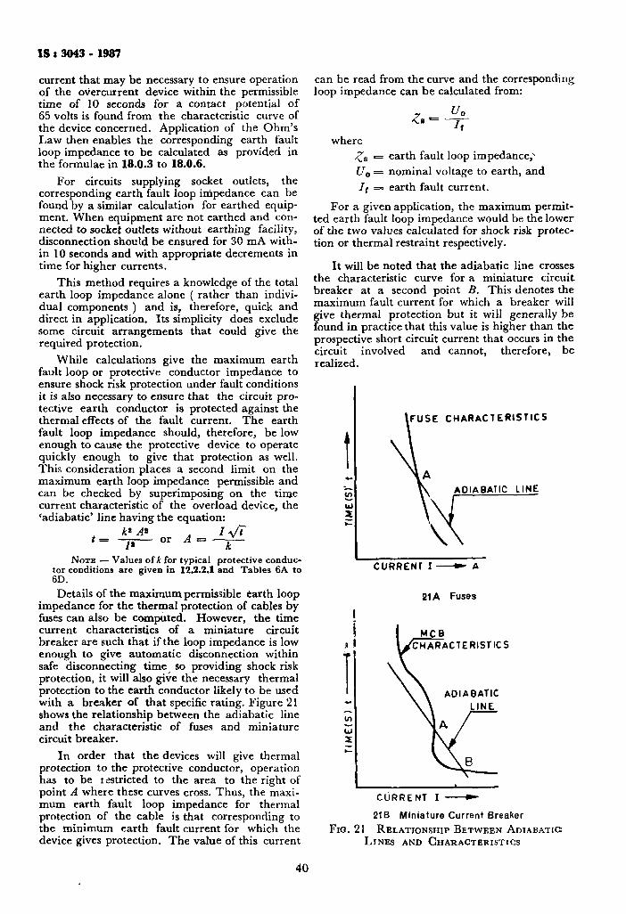
IS t 3043 - 1987
current that may be necessary to ensure operation of the overcurrent device within the permissible time of 10 seconds for a contact potential of 65 volts is found from the characteristic curve of the device concerned. Application of the Ohm's Law then enables the corresponding earth fault loop impedance to be calculated as provided in the formulae in 18.0.3 to 18.0.6.
For circuits supplying socket outlets, the corresponding earth fault loop impedance can be found by a similar calculation for earthed equipment. When equipment are not earthed and connected to socket outlets without earthing facility, disconnection should be ensured for 30 mA within 10 seconds and with appropriate decrements in time for higher currents.
This method requires a knowledge of the total earth loop impedance alone ( rather than individual components ) and is, therefore, quick and direct in application. Its simplicity does exclude some circuit arrangements that could give the required protection.
While calculations give the maximum earth fault loop or protective conductor impedance to ensure shock risk protection under fault conditions it is also necessary to ensure that the circuit protective earth conductor is protected against the thermal effects of the fault current. The earth fault loop impedance should, therefore, be low enough to cause the protective device to operate quickly enough to give that protection as well. This consideration places a second limit on the maximum earth loop impedance permissible and can be checked by superimposing on the time current characteristic of the overload device, the 'adiabatic' line having the equation:
can be read from the curve and the corresponding loop impedance can be calculated from:
t = 1* or A — NOTE — Values of A for typical protective conduc
tor conditions are given in 12.2.2.1 and Tables 6A to 6D. Details of the maximum permissible earth loop
impedance for the thermal protection of cables by fuses can also be computed. However, the time current characteristics of a miniature circuit breaker are such that if the loop impedance is low enough to give automatic disconnection within safe disconnecting time so providing shock risk protection, it will also give the necessary thermal protection to the earth conductor likely to be used with a breaker of that specific rating. Figure 21 shows the relationship between the adiabatic line and the characteristic of fuses and miniature circuit breaker.
In order that the devices will give thermal protection to the protective conductor, operation has to be restricted to the area to the right of point A where these curves cross. Thus, the maximum earth fault loop impedance for thermal protection of the cable is that corresponding to the minimum earth fault current for which the device gives protection. The value of this current
£s = u0
where gB t= earth fault loop impedance,-1
U0 = nominal voltage to earth, and Jt = earth fault current.
For a given application, the maximum permitted earth fault loop impedance would be the lower of the two values calculated for shock risk protection or thermal restraint respectively.
It will be noted that the adiabatic line crosses the characteristic curve for a miniature circuit breaker at a second point B. This denotes the maximum fault current for which a breaker will give thermal protection but it will generally be found in practice that this value is higher than the prospective short circuit current that occurs in the circuit involved and cannot, therefore, be realized.
FUSE CHARACTERISTICS
ADIABATIC LINE
CURRENT I » - A
21A Fuses
MCB ^CHARACTERISTICS
\ \ ADIABATIC \ \ LINE
N|A /
\ \ B ^
CURRENT I » -
21B Miniature Current Breaker Fio. 21 RELATIONSHIP BETWEEN ADIABATIC
LINES AND CHARACTERISTICS
40
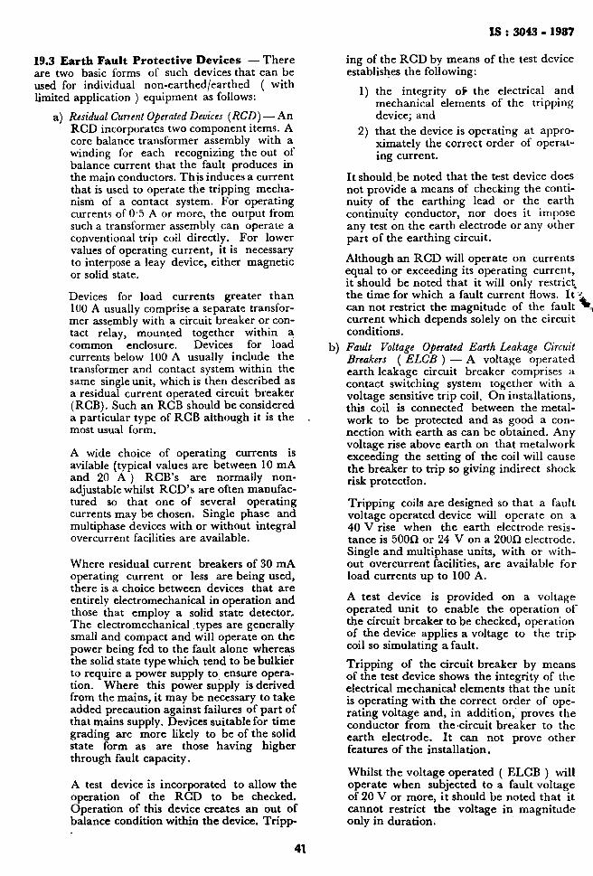
IS : 3043 . 1987
19.3 Earth Fault Protective Devices — There are two basic forms of such devices that can be used for individual non-earthed/earthed ( with limited application ) equipment as follows:
a) Residual Current Operated Devices (RCD) — An RCD incorporates two component items. A core balance transformer assembly with a winding for each recognizing the out of balance current that the fault produces in the main conductors. This induces a current that is used to operate the tripping mechanism of a contact system. For operating currents of 0 5 A or more, the output from such a transformer assembly can operate a conventional trip coil directly. For lower values of operating current, it is necessary to interpose a leay device, either magnetic or solid state.
Devices for load currents greater than 100 A usually comprise a separate transformer assembly with a circuit breaker or contact relay, mounted together within a common enclosure. Devices for load currents below 100 A usually include the transformer and contact system within the same single unit, which is then described as a residual current operated circuit breaker (RGB). Such an RCB should be considered a particular type of RGB although it is the most usual form.
A wide choice of operating currents is avilable (typical values are between 10 mA and 20 A ) RCB's are normally non-adjustable whilst RGD's are often manufactured so that one of several operating currents may be chosen. Single phase and multiphase devices with or without integral overcurrent facilities are available.
Where residual current breakers of 30 mA operating current or less axe being used, there is a choice between devices that are entirely electromechanical in operation and those that employ a solid state detector. The electromechanical types are generally small and compact and will operate on the power being fed to the fault alone whereas the solid state type which tend to be bulkier to require a power supply to ensure operation. Where this power supply is derived from the mains, it may be necessary to take added precaution against failures of part of that mains supply. Devices suitable for time grading are more likely to be of the solid state form as are those having higher through fault capacity.
A test device is incorporated to allow the operation of the RCD to be checked. Operation of this device creates an out of balance condition within the device. Tripp
ing of the RCD by means of the test device establishes the following:
1) the integrity ofc the electrical and mechanical elements of the tripping device; and
2) that the device is operating at approximately the correct order of operating current.
Itshould.be noted that the test device does not provide a means of checking the continuity of the earthing lead or the earth continuity conductor, nor does it impose any test on the earth electrode or any other part of the earthing circuit.
Although an RCD will operate on currents equal to or exceeding its operating current, it should be noted that it will only restrict the time for which a fault current flows. It i can not restrict the magnitude of the fault ^ current which depends solely on the circuit conditions.
b) Fault Voltage Operated Earth Leakage Circuit Breakers ( ELCB ) — A voltage operated earth leakage circuit breaker comprises a contact switching system together with a voltage sensitive trip coil. On installations, this coil is connected between the metal-work to be protected and as good a connection with earth as can be obtained. Any voltage rise above earth on that metalwork exceeding the setting of the coil will cause the breaker to trip so giving indirect shock risk protection.
Tripping coils are designed so that a fault voltage operated device will operate on a 40 V rise when the earth electrode resistance is 500£2 or 24 V on a 200Q electrode. Single and multiphase units, with or without overcurrent facilities, are available for load currents up to 100 A.
A test device is provided on a voltage operated unit to enable the operation of the circuit breaker to be checked, operation of the device applies a voltage to the trip coil so simulating a fault. Tripping of the circuit breaker by means of the test device shows the integrity of the electrical mechanical elements that the unit is operating with the correct order of operating voltage and, in addition, proves the conductor from the-circuit breaker to the earth electrode. It can not prove other features of the installation.
Whilst the voltage operated ( ELCB ) will operate when subjected to a fault voltage of 20 V or more, it should be noted that it cannot restrict the voltage in magnitude only in duration.
4t
IS : 3043 - 1987
c) Current Operated Earth Leakage Circuit Breakers— For industrial applications, ear th leakage circuit breakers operating on mil l iampere residual currents or working on fault voltage principle are of little use, since milli-amperes of earth leakage current for an extensive industrial system is a normal operat ing situation. Tripping based on these currents will result in nuisance for the normal operat ion. Milliamperes of current in a system, where exposed conductive parts of equipments are effectively earthed and fault loop impedance is within reasonable values, will give rise only to a ground potential/contact potential rise of a few millivolts. This will in no way contribute to shock or fire hazard . H e r e objectionable fault currents will be a few or a few tenths of amperes . In such cases, residual current opera ted devices sensitive to these currents must be m a d e use of for earth fault current and stable operation of the plant without nuisance tripping./ This is achieved either by separate relays or in-built releases initia t ing trip signals to the circuit-breakers ( For details, refer to Section 5 ).
19.4 Se l ec t ion o f Ear th Faul t Pro tec t ive D e v i c e s — In general, residual current operated devices are preferred and may be divided into two groups according to their final current operating characteristics.
a) RCD's Having Minimum Operating Currents Greater Than 30 mA — These devices are intended to give indirect shock risk protection to persons in contact with earthed metal.
t>) RCD's Having Minimum Operating Current of 30 mA and Below — These devices are generally referred to as having 'high sensitivity' and can give direct shock risk protection to persons who may come in contact with live conductors and earth provided that the R C D operating times are better than those given in IS : 8437-1977*. It should be noted that such R C D ' s can only be used to supplement an earth conductor and not replace one.
I n addit ion to giving protection against indirect contact or direct contact R C D ' s may also give fire risk protection, the degree of protection being related to the sensitivity of the device.
An R C D should be chosen having the lowest suitable operating current. The lower the operating current the greater the degree of protection given, it can also introduce possibilities of nuisance tripping and may become unnecessarily expensive.
♦Guide on effects of current passing through the human body.
The minimum operating current will be above any standing leakage that may be unavoidable on the system. A further consideration arises if it is intended to have several devices in series. It is not always possible to introduce time grading to give discrimination whereas a limited amount of current discrimination can be obtained by grading the sensitivities along the distribution chain.
The maximum permitted operating current depends on the earth fault loop impedance. The product of the net residual operating current loop impedance should not exceed 65 volts.
I t is often acceptable on commercial grounds to have several final circuits protected by the same residua] current devices. This, however, does result in several circuits being affected if a fault occurs on one of the circuits so protected and the financial advantages have to be weighed against the effects of loosing more than one circuit.
I t should also be noted that different types of R C D in different circuits may react differently to the presence of a neutral to eaith fault on the load side. Such an earth connection together with the earthing of the supply at the neutral point will constitute a shunt across the neutral winding on the R C D transformer. Consequently, a portion of the neutral load current will be shunted away from the transformer and it may result in the device tripping. On the other hand, such a shunt may reduce the sensitivity of the device and prevent its tripping even under line to earth fault conditions. In general, therefore, care should be taken to avoid a neutral to earth fault where R C D ' s are in use, although there are some designs being developed that will detect and operate under such conditions. On installations with several RCD's , care should be taken to ensure that neutral currents are returned via the same device that carries the corresponding phase current and no other. Failure to observe this point could result in devices tripping even in the absence of a fault on the circuit they are protecting.
When using fault voltage operated ELCB's, the metalwork to be protected should be isolated from earth so that any fault current passes through the tripping coil gives both shock and fire risk protection. However, this isolation is not always practicable and the presence of a second parallel path to earth will reduce the amount of fire risk protection offered. Because the coil is voltage sensitive, the presence of such a parallel path wil! not reduce the shock risk protection offered provided that this second path goes to earth well clear of the point at which the earth leakage circuit breaker trip coil is earthed. It is required that the earthing conductor is insulated to avoid contact with other protective conductors or any exposed conductive parts or extraneous conductive parts so
42
IS : 3043 - 1987
as to prevent the voltage sensitivity element from being shunted, also the metalwork being protected should be isolated from that associated with other circuits in order to prevent imported faults.
Voltage operated ELGB's are suitable for protection of isolated installations on a T T system such as occur in rural areas. Table 9 shows the maximum earth electrode impedance with switch different types of breaker may be used.
TABLE 9 MAXIMUM EARTH ELECTRODE RESISTANCE FOR DIFFERENT TYPES OF
CIRCUIT BREAKER T Y P E OF BKKAKBB
RCD
Voltage Operated ELCB
O P E R A T I N G CuBBENT
300 mA
f 30 mA I -
M A X I M U M E A B T H ELECTRODE
RESISTANCE (£1)
166
1 666 500
SECTION 4 POWER STATIONS, SUBSTATIONS AND OVERHEAD LINES
20. E A R T H I N G I N P O W E R STATIONS A N D SUBSTATIONS
20.1 Genera l — In general , earthing installations will be required at power stations and substations for:
a) T h e neutral points of each separate electricity system which has to be earthed at the power station or substation;
b) Apparatus fremework or cladding or other non-current carrying metalwork associated with each system, for example, transformer tanks, power cable sheaths;
c) Extraneous metalwork not associated with the powersystems, for example boundary fences, sheaths of control or communicat ion cables.
For safety, the objective of earth bonding is to ensure that , in normal or abnormal conditions, any voltage appearing on equipment to which there is access should be below a dangerous level. It is not practicable to ensure that metal parts are earthed and remain near t rue ear th potential during the passage of earth fault currents, particularly on high voltage systems with directly earthed neutrals. T h e objective should, therefore, be to provide effective bonding of low impedance and adequate current-carrying capacity between parts with which anyone may be in simultaneous contact, and to arrange, as far as possible, tha t large fault currents do not flow between such points.
T o minimize risk of damage to certain auxiliary plant, the rise of potential of a station ear thing installation above the potential of true or remote ear th should be as low as practicable, since this potential will be applied across protective insulation of any plant with connections to earth external to the substation, for example, plant with connections to pilot or telephone cables or cable sheaths. For similar reasons, the potential difference between earthed points in the station should also be kept to a minimum. Where surge protection is provided, the connection of the protective devices to ear th should be as direct as possible. T h e discharge of high currents with high-frequency components requires earth connections of low resistance and reactance, that is, short connections with as few changes of direction as possible.
Where the neutral points of two electrically separate electricity systems are connected to a common earth electrode system at a site, there is a coupling of the systems in the event of an earth fault occurring on either system by virtue of the rise of earth potential due to the passage of the fault current through the earth electrode system. Similarly, if non-current carrying metalwork is bonded to the same earth electrode as the neutral point of the supply the metalwork will experience the same rise of earth potential. If complete separation of electrical systems were required, it would be essential that the neutral points of each system and its associated metalwork be separately earthed. If such a method were adopted, each earthing system would require insulation from other earthing systems to withstand the maximum rise of earth potential occurring in any system by virtue of lightning currents or power system fault currents. Insulation to this level is rarely practicable.
T h e choice of using a common ear th or separa te earths for the system of different voltages at a transforming point affect:
a) the probability of breakdown occurring in a transformer between the higher and lower voltage sides due to lighting or other surges; and
b) the safety of consumers or their proper ty supplied by any low voltage system distributed from the station against arise of potential of the earthed neutral by a high voltage system ear th fault at the station.
T h e former risk is reduced by use of a common earth system, and the latter danger only arises if the resistance of the ear th electrode system is not sufficiently low to limit the rise of earth potential to a safe value. The re is advantage in using a common earth where the earth electrode resistance, including the parallel resistance of any bonded metalwork, etc, t o ear th is 1 Q, or less, as is usual at power stations, large outdoor substations or substations supplying a network of cables whose sheaths have a low impedance to ear th .
T h e substation earth system rise of potential will not be excessive if the resistance of the earth electrode system is small compared to the total earth fault circuit impedance. Systems of higher
43
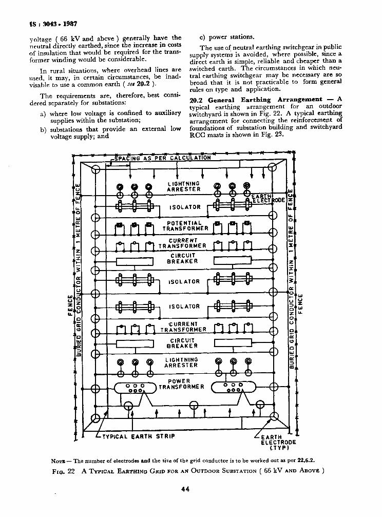
IS : 3043 • 1987
yoltage ( 66 kV and abcve ) generally have the neutral directly earthed, since the increase in costs of insulation that would be required for the transformer winding would be considerable.
In rural situations, where overhead lines are used, it may, in certain circumstances, be inadvisable to use a common earth ( set 20.2 ).
The requirements are, therefore, best considered separately for substations:
a) where low voltage is confined to auxiliary supplies within the substation;
b) substations that provide an external low voltage supply; and
c) power stations. The use of neutral earthing switchgear in public
supply systems is avoided, where possible, since a direct earth is simple, reliable and cheaper than a switched earth. The circumstances in which neutral earthing switchgear may be necessary are so broad that it is not practicable to form general rules on type and application. 20.2 General Ear th ing Arrangement — A typical earthing arrangement for an outdoor switchyard is shown in Fig. 22. A typical earthing arrangement for connecting the reinforcement of foundations of substation building and switchyard RCG masts is shown in Fig. 23.
u
u. u.
! 1 0
u
re |pAd'lNGffAS"PER' C A L C U L A T T O N '
JO " I -u a o o
: i— o: C9
a
a <>
a
EFF:f 144- LIGHTNING
ARRESTER
< H ^ i—i n
8 SS w\
ISOLATOR &zM> htlty tODE
nnn POTENTIAL TRANSFORMER nnn o
CURRENT ^i^T.»as«"» nnn ^ CIRCUIT
BREAKER >
4^#" ISOLATOR ^ ^
O
«
<M^ ISOLATOR * = £ * o -o
n n n TRANSFORMER n n n — Q
***. " * U-; I
O i til ac
a.
EARTH ELECTRODE
( T Y P )
NOTB — The number of electrodes and the size of the grid conductor is to be worked out as per 22.6.2.
F I G . 22 A T Y P I C A L EARTHING G R I D FOR AN O U T D O O R SUBSTATION ( 66 kV AND ABOVE )
44
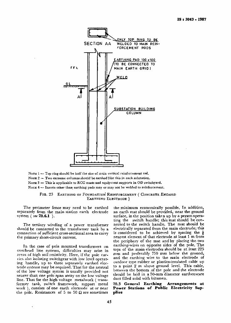
IS t 3043 . 1987
SECTION AA .ONLY TOP RINS TO BE WELDED TO MAIN REINFORCEMENT RODS
FFL
GL „
I
s
EARTHING PAD 100x100 /(TO BE CONNECTED TO
MAIN EARTH GRID)
WELD
J SUBSTATION BUILDING
' COLUMN
NOTE 1 — Top ring should be half the size of main vertical reinforcement rod. N O T E 2 — Two extreme columns should be earthed like this in each substation. N O T E 3 — This is applicable to RCG masts and equipment supports in OD switchyard. N O T E 4 — Inserts other than earthing pads may or may not be welded to reinforcement.
Fio. 23 EARTHING OF FOUNDATION REINFORCEMENT ( CONCRETE ENCASED EARTHING ELECTRODE )
The perimeter fence may need to be earthed separately from the main station earth electrode system ( see 20.6.1 ).
The tertiary winding of a power transformer should be connected to the transformer tank by a connection of sufficient cross-sectional area to carry the primary short-circuit current.
In the case of pole mounted transformers on overhead line systems, difficulties may arise in areas of high soil resistivity. Here, if the pole carries also isolating switchgear with low level operating handle, up to three separately earthed electrode systems may be required. That for the neutral of the low voltage system is usually provided not nearer than one pole span away on the low voltage line. That for the high voltage metalwork ( transformer tank, switch framework, support metal work ), consists of one earth electrode at or near the pole. Resistances of 5 to 50 ii are sometimes
the minimum economically possible. In addition, an earth mat should be provided, near the ground surface, in the position taken up by a person operating the switch handle; this mat should be connected to the switch handle. The mat should be electrically separated from the main electrode; this is considered to be achieved by spacing the J nearest element of that electrode at least 1 m from the periphery of the mat and by placing the two earthing-wires on opposite sides of the pole. The tops of the main electrodes should be at least 225 mm and preferably 750 mm below the ground, and the earthing wire to the main electrode of outdoor type rubber or plastics-insulated cable up to a point 2 m above ground level. This cable, between the bottom of the pole and the electrode should be laid in a 50-mm diameter earthenware duct filled solid with bitumen. 20.3 General Ear th ing Ar rangemen t s a t Power Stat ions of Public Electr ici ty Supplies
45
IS i J043 - 1987
20.3.1 Neutral Earthing of Generator Circuits — At modern large power stations for public electricity supply the generation circuits generally comprise a star-connected stator circuit with an operating voltage up to about 26 kV, directly connected to a step-up delta/star transformer, the higher voltage winding generally operating at 132 Vk, 275 kV or 400 kV, with the transmission system neutral point directly earthed.
T h e following three methods have been used for earthing the neutral of the generator windings:
a) Earthing through the primary winding of a matching transformer, with resistor connected across the secondary winding;
b) earthing through a resistor; and c) earthing through the primary winding of
a voltage transformer.
Method (a) — is current practice, the design being such that the maximum substained earth fault current in the generator circuit is restricted to 10 to 15 A, thus limiting the damage at the point of fault. T h e neutral and earthing connections, however, are of adequate capacity to withstand for 3 s the earth fault current that would flow in the event of the matching transformer terminals flashing over during an earth fault. T h e resistor used for the arrangement is of the metallic grid non-inductive type.
Method (b) — can be used to achieve the same degree of fault-current limitation, by design of a suitable high-current resistor, but is not preferred on the grounds of cost and its less robust construction than that of the equipment used in method (a) . I t was earlier practice, however, to individually earth each generator at rJower stations by liquid earthing resistors designed to limit the earth-fault current to about 300 A.
Method (c) —is now historic, but had the advantage that minimal damage resulted at an ea r th fault. If desired, the generator could remain in circuit while operational arrangements were made to permit its withdrawal. However, this imposed a higher voltage stress on the stator windings and plant on the unfaulted phases, and the machine design usually imposed limitations on this. The output from the secondary winding of the voltage transformer could be arranged to activate an alarm or trip the generator circuit as desired. In designing the neutral and earthing connections to the voltage transformer, the earth-fault current used was that resulting by flashover of the voltage transformer during an earth fault.
Some old power stations have generators connected directly to distribution system busbars; in general, the neutral terminals of such generators have been earthed via liquid neutral earthing resistors of such a value that the maximum sustained earth fault current is of the order of full load current of the generator. Installations of neutral point switchboards with switching of neutral points a n d
earthing resistors have been abandoned in favour of individual unswitched earthing resistors .
20.3.2 Earthing of Power Station Auxiliary Systems — There are, in common use, three methods of earthing the neutral point in power station auxiliary systems:
a) Solid earthing; b) earthing through a voltage transformer ( or
voltage relay ) with a surge diverter ( but not a fuse ) shunting the primary winding ( or the relay);
c) Resistance earthing.
Methods (a) and (c) involve the automatic disconnection of the individual fault circuit.
With method (b), an alarm can be arranged to be operated from the secondary of the'voltage transformer and the scheme enables all auxiliaries to be kept in service until it is convenient to make the auxiliary switchboard dead.
Method (a) is normally used in power stations with smaller generating sets and method (c) used in the larger power stations. Method (b) has certain disadvantages, such as the complication in arranging for speedy identification of the individual faulty circuit and the possible difficulties arising from functioning of the surge diverter.
20.4 E q u i p m e n t E a r t h i n g a t P o w e r S t a t i o n s — Practice in equipment earthing at power stations is identical to that for large substations not giving external low voltage supplies ( see 20.2 ). A common earth is used for the neutral earthing of generators and power station auxiliaries, and for all equipment framework, cladding, power cables sheaths and extraneous metalwork not associated with the power systems, other than the perimeter fence ( see 20.6.1. ) .
20.5 P o w e r S ta t ion a n d S u b s t a t i o n E a r t h E l e c t r o d e s
20.5.1 General — T h e required characteristics of ear th electrode system are:
a) a suitably low resistance, under all variations due to climatic conditions, for the fault currents envisaged;
b) current carrying capability for all currents and durations that may arise in normal operating conditions or during fault or surge discharge conditions, without undue increase in resistance;
c) suitable location in the vicinity of any lighting discharge devices such that earth connection conductors from such devices are as short and straight as possible to minimize surge impedance; and
d) earth electrode installations should be durable and of such material and design to avoid corrosions.
46

IS : 3043 ■ 1987
For high voltage system earthing, the value of the resistance of the earth electrode system, with any adventitious earths due to the bonding of metalwork, etc, in contact with earth, should be such that the rise in potential of the electrode system above the potential of remote earth is as low as economically possible. In the absence of any specific restriction, attempt should be made to restrict the rise of potential within safe value. At some sites; the rise in earth potential will inevitably exceed these values, and special precautions are necessary.
Where the soil of a site is hostile by virtue of alkalinity or acidity it may be necessary to embed ■earth electrodes in rammed neutral soil to avoid ■corrosion.
Earth electrode systems can also represent some hazard to adjacent underground services or structural steelwork through electrolytic action between dissimilar metals ( see 23 ). Where this danger cannot be avoided by selection of compatible metals, the adoption of cathodic protection or other remedical action may be necessary.
At power stations and substations the steel inforcement in foundations and piles can be used to provide an effective electrode system, without necessity to provide further buried electrodes. Where piles are used they should be bonded by welding and connected to earth bonding bars at least four points.
Where no substantial adventitious earths exist or where they are in adequate, it is necessary to install electrodes ( see 9.1, 9-2 and 12.1.1 ).
All cladding or steel work at a station should be bonded to the earthing system as should all structural steel work, but attention is drawn to precautions against undue reliance on the latter as an electrode.
20.5.2 Choice and Design — Where electrodes •of large surface area are necessary to provide the requisite current carrying capacity, earth plates are recommended. These are generally of cast-iron, not less than 12*5 mm thick, and are usually 1'22 m by T22 m. As an alternative to plates, cast iron pipes may be installed. These are, for example, about 100 mm in diameter and 3 m long, but are not generally as cost-effective as plates for equivalent surface area.
For lower current rating requirements, driven rods are preferred, usually, of die copper-clad steel type. They are generally driven in groups, preferably with a spacing of not less than their length, although this is not always achievable. Closer spacing reduces their effectiveness. The use of driven rods is advantageous where the deeper stratas of a site have a lower resistivity than the upper stratas but they may not be suitable if the site is stony or has a rock sub-strata.
At large substation compounds, it is usual to lay a mesh of underground earth strips to which system neutral terminals and the earth bonding conductors from above-ground structures are connected. In addition to providing an approximately equi-potential surface over the substation, the earth strip mesh frequently suffices to provide an electrode of suitable resistance and current carrying capacity without augmentation.
20.6 Earthing Conductors for Power Stations and Substations
20.6.1 Disposition — It is necessary to provide permanent and substantial connections between all equipment and the earth electrodes so as to afford a low resistance path for fault currents both to earth and between items of equipment. In addition, all other metal plant in or about the station should be connected to the main station earthing system. The most efficient disposition of earthing conductors required will depend on the layout of equipment and the following may be taken as a guide:
a) Indoor Equipment — A main earth bar should be provided and connected to the framework of each item and to the earth-electrodes. Except for the smallest installations, there should be a connection to the earth electrodes at each end of the earth bar or, if this is in the form of a ring, at several points on the ring. These Connections may, depending on the layout be buried cables of a size adequate for the short-circuit current. Where the structure of a switchboard is extensive or occupies more than one floor, a further parallel main earth bar may be required which should be cross-connected to its companion bar at one point at least in each section of the switchboard.
The main earthbar should be so placed that cable sheaths can be readily connected to it. When cables are so connected, the bonds should be made to the cable gland on which the lead sheath should be plumbed and the armouring clamped. The main earth bar should be accessible for the connection of any detachable earthing devices provided with the switchgear.
Branch connections from the main earth bar should be provided to all accessory equipment, such as control and relay panels, constructional steelwork and fire-extinguishing equipment.
Where busbar protection is effected at switchboards by frame leakage, two main earth bars are required. The frame bar interconnecting the framework of the switch units will be connected to the true earth bar through a current transformer and bolted links for test purposes. The true earth bar should be run separately from the frame earth bar in convenient position for the
47
IS t 3043 . 1987
connection of cable sheaths and earthing devices. Where it is mounted on the switch units, it should be insulated therefrom by insulation capable of withstanding a test voltage of 4 kV rms alternating current for 1 minutes.
Where insulated cable glands are used, it is recommended that 'island' insulation should be provided to facilitate testing.
b) Outdoor Equipment ( Excluding Pole Mounted Transformers ) — A main earth bar should be provided, so disposed as to allow of the shortest subsidiary connections to all major equipment, such as transformers or circuit breakers. Wherever possible, this should be arranged to form a ring round the station. The main earth bar ( or ring) should be connected where required to earth electrodes. For larger stations, the ring should be reinforced by one or more cross-connections.
From the main earth bar, branch connections should be taken to each item of apparatus and where several such items lie together, a , subsidiary ring with short branches is preferable to a number of longer individual branches from the main bar. The aim should be to provide a mesh system wherever this can be contrived with reasonable economy.
The operating mechanisms for outdoor airbreak switch disconnectors and earth switches and circuit breaker control kiosks, etc, not integral with the circuit breaker should be connected to the main earth grid by a branch earth connection entirely separate from that employed for earthing the air-break switch-disconnector or earth switch base, or the circuit-breaker structure. The further contribution to safety given by an insulated insert in the mechanism drive is small compared with that obtained from such a branch earth connection and, therefore, insulated inserts are not recommended in operating mechanisms of apparatus installed in substations. While sites covered with hard core and stone chippings will constitute a surface layer with a relatively high specific resistance, in .the interests of safety, a metal grid can be provided at the operating points to give a level standing area and an earth connection made from this grid to the operating handle.
Where it can be proved that the current carrying capacity of a main aluminium or steel member or welded sections forming a structure are at least equal to that of the required aluminium or copper earth conductor, the structure may form part of the connection and thece is no need to fix an «arth conductor along this section. A struc
ture made up of bolted sections should not be relied upon to form an efficient earth bond between equipment and the main earth grid, and loops bonding across structural joints are required.
Connections to metal cladding, steel structure and metal door frames and windows or any other metallic panels should be made inside buildings.
Where the earth wire of an incoming line ends at the terminal supports and is not connected to a point on the substation structures, a subsidiary earth connection should be provided between the substation earth system and the base of the support. If the latter lies outside the sub-station fence, the earth connection should be buried where it passes under the fence and should be kept well clear of the latter.
Earth connections to surge diverters should be of sample cross-section and as direct as possible; they should not pass through iron pipes which would increase the impedance to surges of the connection. The earth connections of the diverters should be interconnected with the main earthing system since, for the effective protection of the substation equipment, a definite connection of low impedance bptween the equipment and the diverters is essential.
20.6.2 Design
20.6.2.0 General — The term earthing grid applies only to that part of the grid which is buried in soil. For design calculations of the grid resistance to the soil, only the buried part of the grid is to be taken into account. That part of the grid which lies embedded in concrete and also reinforcement connected to the grounding pads do lower the combined grid resistance but this contribution may not be taken into account while designing the earthing grid.
20.6.2.1 Conductors installed above ground — Earthing conductors for power stations and substations will normally be selected from copper or aluminium or steel sections adequately rated in size to carry the designed earth fault or three phase fault current for the appropriate designed maximum duration without exceeding a temperature given in Table 6A. Compliance with this requirement will additionally ensure satisfactory bonding without excessive voltage difference along any conductor.
The required cross-sectional area of the earthing conductor is determined by the choice of conductor material and the maximum duration of the fault current. The generally accepted duration for design purposes are one second for voltages above 33 kV and 3 seconds for lower voltages.
48
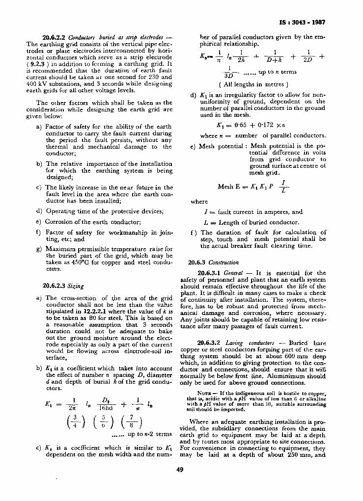
IS : 3043 ■ 1987
20.6.2.2 Conductors buried as strip electrodes — The earthing grid consists of the vertical pipe electrodes or plate electrodes interconnected by horizontal conductors which serve as a strip electrode ( 9.2.3 ) in addition to forming a earthing grid. It is recommended that the duration of earth fault current should be taken as one second for 230 and 400 kV substations, and 3 seconds while designing earth grids for all other voltage levels.
The other factors which shall be taken as the consideration while designing the earth grid are given below:
a) Factor of safety for the ability of the earth conductor to carry the fault current during the period the fault persists, without any thermal and mechanical damage to the conductor;
b) The relative importance of the installation for which the earthing system is being designed;
c) The likely increase in the near future in the fault level in the area where the earth conductor has been installed;
d) Operating time of the protective devices;
e) Corrosion of the earth conductor; f) Factor of safety for workmanship in join
ting, etc; and g) Maximum permissible temperature raise for
the buried part of the grid, which may be taken as 450°G for copper and steel conductors.
20.6.2.3 Sizing
a) The cross-section of the area of the grid conductor shall not be less than the varue stipulated in 12.2.2.1 where the value of k is to be taken as 80 for steel. This is based on a reasonable assumption that 3 seconds duration could not be adequate to bake out the ground moisture around the electrode especially as only a part of the current would be flowing across electrode-soil interface,
b) Kt is a coefficient which takes into account the effect of number n spacing D, diameter d and depth of burial h of the grid conductors.
Kt = 1
2-K L Ds
16hd + 1 In
(4-) (v) (4-) up to n-2 terms
c) Ke is a coefficient which is similar to A\ dependent on the mesh width and the num
ber of parallel conductors given by the em-phirical relationship.
1 1 *•.' -1 i-L-1
-4- + 3D
D+h ^ 2D
up to n terms
+
( All lengths in metres ) d) K\ is an irregularity factor to allow for non-
uniformity of ground, dependent on the number of parallel conductors in the ground used in the mesh.
K{ = 0-65 + 0-172 xn where n = number of parallel conductors.
e) Mesh potential : Mesh potential is the potential difference in volts from grid conductor to ground surface at centre of mesh grid.
Mesh E = Kt K1 P -L-
where / = fault current in amperes, and L =s Length of buried conductor.
f) The duration of fault for calculation of step, touch and mesh potential shall be the actual breaker fault clearing time.
20.6.3 Construction 20.6.3.1 General — It is essential for the
safety of personnel and plant that an earth system should remain effective throughout the life of the plant. It is difficult in many cases to make a check of continuity after installation. The system, therefore, has to be robust and protected from mechanical damage and corrosion, where necessary. Any joints should be capable of retaining low resistance after many passages of fault current.
20.6.3.2 Laving conductors — Buried bare copper or steel conductors forming part of the earthing system should be at about 600 mm deep which, in addition to giving protection to the conductor and connections, should ensure that it will normally be below frost line. Aluminimum should only be used for above ground connections.
N O T E — If the indigeneous soil is hostile to copper, that is, acidic with a pH value of less than 6 or alkaline with a^H value of more than 10, suitable surrounding soil should be imported.
Where an adequate earthing installation is provided, the subsidiary connections from the main earth grid to equipment may be laid at a depth and by routes most appropriate to site connections. For convenience in connecting to equipment, they may be laid at a depth of about 250 mm, and
49
18:3043-1987
as they are, therefore, in ground more subject to seasonal or progressive changes of resistivity, it may be assumed that they make negligible contribution towards reducing station earth resistance. On the other hand, they do serve to reduce surface gradient within the station site. Conversely where these connection are also required to improve the earth value of the station, tbe 600 mm depth is required. The above recommendations deal mainly with stations on normal sites. Where ground conditions restrict the installation depth or where the soil resistivity is excessive, additional measures may be required beyond the station boundary to improve the overall earth value.
The earthing installation within the station will, however, bond the station plant and restrict touch potentials to acceptable limits.
Where bare metal conductor is buried under metal fencing, and the fencing is independently earthed, the conductor should be insulated by threading through non metallic pipe extending for at least 2 m each side of the fence or alternatively insulated conductor may be used.
When laying stranded conductor for earthing purposes, care should be taken to avoid birdcaging of the strands.
20.6.3.3 Fixing conductors — In fixing aluminium or copper conductors to structures, etc, insulated elips should be used to avoid drilling and prevent electrolytic action. Galvanized clips should not be used. Fixing should be spaced not more than 1 m apart.
Earth conductors in trenches containing power and/or multi-core cables should be fixed to the walls near the top ( for example, 100 mm from the top ).
Copper earth strip supported from or in contact with galvanized steel should be tinned to prevent electrolytic action.
Sharp bends required in aluminium strip should be formed by the use of a bending machine.
Aluminium earthing conductors will give satisfactory performance in contact with concrete, cement, plaster and brickwork, and may be buried in concrete or plaster, provided it remains dry after setting. In outdoor installations, the conductor will weather to a grey appearance and in marine or industrial atmospheres slight surface pitting may occur. This will not affect performance since the sections are relatively large. The interfaces of all 'mechanical' joints should be protected with a suitable electrical joint compound, particularly any bimetallic joints. All bimetallic joints should then be encapsulated in a grease impregnated tape, mastic compound or bitumastic paint, etc, to exclude moisture.
In general, aluminium should only be used above -ground and the connections to earth ele
ctrodes made above ground with bimetallic joints. Aluminium can be used below ground only if efficiently protected or sheathed against contact with soil and moisture.
20.6.3.4 Jointing conductors a) General — All crossings of conductors in the
main earth grid should be jointed. Compression type joints may be used for stranded conductors. Non-conductor strip should be drilled for a bolt having a diameter greater than one-third of the width of the strip. If this diameter will be exceeded, than a wider flag should be jointed to the strip.
b) Aluminium to aluminium — When possible, joints on strip conductor should be arc welded using either the tungsten inert-gas arc ( TIC ) or metal inert gas arc ( MIG ) techniques. Oxy-acetylene gas welding or brazing may also be used.
Ranges of compression fittings and tools are available for round conductors. Round conductors can also be flattened and punched with suitable tools to form a terminal.
Round and rectangular conductors can be joined with bolted clamps.
Rectangular conductors can be joined or terminated by drilling and bolting. When making a bolted type joint, the surface of the aluminium should be cleaned thoroughly by wire brushing and greased or an approved jointing compound applied immediately to both mating surfaces. Bolts should then be tightened and all excess grease or compound wiped off and discarded.
To ensure adequate contact pressure and avoid overstressing, torque spanners should be used. The conductor manufacturers literature should be consulted for further details for the joints and procedures.
Cold pressure welding and explosive bonding can be used for jointing rectangular conductors. The appropriate manufacturer should be consulted for details of these procedures.
c) Aluminium to copper — Joints between aluminium and copper should be of the bolted type and be installed in the vertical plane at a minimum distance of 150 mm above ground level.
The rating surface of the aluminium should be cleaned thoroughly by wire brushing and greased or an approved jointing compound applied and the copper tinned. Grease or an approved jointing compound should be applied to the melting surface of
so

IS t 3043 - 1987
the aluminium. After bolt tightening by torque spanner, excess grease or compound should be wiped off and discarded, and the joint protected from the ingrease of moisture by the application of suitable plastics compound or irradiated polyethylene sleeve with mastic lining. Alternatively, the joint may be protected by a bitumastic paint.
Aluminium conductor connections to equipment should, where possible, be in the vertical plane. Surface preparation of the aluminium and the making of the joint should be as previously described. The finished joint should be protected by a bitumastic paint.
d) Copper to copper — The following methods may be used: 1) Brazing using zinc-free brazing material
with a melting point of at least 600°G; 2) Bolting; 3) Riveting and sweating; and 4) Explosive welding.
Earthing conductor connections to equipment should, as far as practicable, be made onto vertical surfaces only. In the case of painted metal, the paint should be carefully removed. Earthing conductors should be tinned where connected to galvanized steelwork. No connection point should be less than 150 mm above ground level. In any position, subject to corrosion, the finished joint should be protected by bitumastic paint.
e) Loops for portable earths — Loops of plain aluminium or copper should be provided on the earth conductor at each location where portable earthing leads may be applied. The loops should not be less than 180 mm long and 75 mm clear of the earth conductor; they should be at a convenient height and should be formed separately, not by bending the earth strip itself. Loops should be jointed to the earth conductor using a method given in 20.6.8.4 (d).
f) Steel — For steel, it is recommended to use only welded joints.
20.7 Earthing of High Voltage Cable Sheaths
20.7.1 Three-Core Cables — Modern high voltage power cables are generally provided with a polymeric insulating oversheaths. The sheath of solid tpye cables are generally directly earthed at their terminations and joints, the cable sheaths being bonded at joints. The sheath earth connections of pressure type cables are generally made via a removable link in 'a lockable box to permit periodic testing of the oversheath insulation, the joints being insulated, but the sheaths bonded through. The test requirement also means that insulating glands should be provided at the cable
termination boxes of transformers, switchgear, etc and at cable sealing ends or joints.
20.7.2 Single-Core Cable Tails — The sheaths of single-core cables have a longitudinal induced voltage, the magnitude of which is directly proportional to the current flowing in the core. When both ends of a single-core cable are bonded to earth, a current flows in the sheath and the thermal effects of this sheath current derates the capacity of the cable core. Where this derating is unacceptable and the value of the standing induced voltage is acceptable, it is usual to earth the sheaths of the single-core cables at the trifurcating box or in the case of single-core mains, the end of the trefoil formation, the cable glands at sealing ends or plant cable boxes being of the insulated type. The acceptable level of the maximum sheath voltage is generally taken as 65V with full rated current flowing in the cable, but where the ratio of fault current to full rated current is so high that the voltage developed across an insulated gland is unacceptable, it is necessary to derate the permissible voltage to some level lower than 65 V.
20.7.3 Single-Core Cable Mains — The choice of termination and earthing arrangements for single-core cable mains is a matter of economics. The possible methods of earthing are as follows:
a) Solid Bonding — In this system, the sheath bonding and earthing arrangements are such that the sheaths are maintained near earth potential throughout their length.
b) Single Point Bonding — This method is as described in 20.7.2 for single core tails, and is subjected to practical limitations of cable lengths permissible.
c) Cross-Bonding — In this method, the cable length is divided into three equal sections ( or into a multiple of three such sections ) and at each section junction, an insulating joint is provided. At these joints, the sheath of each cable section is bonded to the sheath of a different phase cable of the next section through lockable link boxes. By suitable connection, the phaser sum of the longitudinal sheath voltage is zero, and at the cable terminations, the sheaths of all three cables are bonded to earth. It is usual to provide a three-phase star-connected set of cable protections at each intermediate insulating joint; these protectors are non-linear resistors presenting low impedance to surge currents. The cross-bonding method permits the full rating of the cable to be maintained, but incurs considerable cost in the provision of insulating joints, link boxes, protectors, etc.
20.8 Miscellaneous Matters in Power Stations and Substations — If two or more stations are adjacent on what may be considered to be one site, the earthing systems and the stations should be interconnected to form a single earthing
51
I S : 3043 -1987
system. Where the stations actually adjoin, the extremities of their earthing systems should be connected together so that the whole area is enclosed by the earthing system. Where the separation is too large to treat as adjoining stations, an interconnecting earth conductor of substantial cross-section should be run to ensure that , as far as practicable, fault currents are diverted from cable sheaths and armour. This is of particular imporatnce where fault current flowing in one station is provided from the adjoining station, for example, where a switching station adjoins power or transforming station sites so tha t an earth fault in the switchgear causes current flow between the two sites in order to reach the system neutral at the generators or transformers. Such interconnections between sites can include links suitably disposed to assist in testing.
Except where special insulation is called for, sheaths of all main cables should be connected to the station earth system. With multi-core cables the connection is generally made at the termination.
Where high earth-fault currents a re to be expected, and an appreciable rise of potential of the station system with respect to the general body of the earth may ensure, special care is necessary with connections other than main cables or lines entering the station, such as water pipes and telephone or pilot cables, water pipes should include a n insulated section; polymeric piping is often suitable. In several cases, isolating transformers may be necessary for telephone connections. British Telecom provides isolation equipment at their circuit terminations when the potential rise exceeds 430 V ( 650 V for high reliability lines ) . Pilot cables should be provided with insulated glands and so disposed as to minimize the possibility of fauttt currents being carried by the sheaths.
Where carrier-current equipment is employed, a further earth-electrode, normally a driven rod, should be provided at or immediately adjacent to each structure supporting the coupling capacitors. This ear th electrode is an additional one for the high frequency equipment and should be bonded in to the main earthing system. T h e structures supporting the coupling capacitors should be earthed in the normal way.
2 1 . E A R T H I N G ASSOCIATED WITH O V E R H E A D POWER LINES
21.1 T y p e o f Support — A n y consideration of "whether metalwork associated with overhead power lines should be earthed and/or bonded has t o take account of the type of support. Some overhead lines are supported by lattica towers of metallic construction, others by poles, which may be of steel, wood, concrete or of fabricated cons
t ruc t ion , for example, glass-reinforced plastics; brackets attached to buildings are also used to
support conductors.
21.2 Insu la t ion Fai lure — Following an insulation failure, a voltage may exist between any supporting metalwork and earth. The public are generally protected if no metalwork within 3 m of the ground is liable to become live on failure of insulation. If the supports are close to buildings, etc, the particular circumstances have to be considered.
21.3 Lat t i ce Steel Structures — There will often be satisfactory earthing of lattice steel structures, poles of metallic construction and reinforced concrete poles through their contact with the ground. In areas of high earth resistivity, special earthing arrangements may be necessary; an overhead protective conductor attached at each support and connected to the neutral of the supply and of the line may be the most economical solution. This conductor if positioned above the live conductors, will also provide a measure of lightning protection.
21.4 Po le s o f Non-conduct ing Mater ia l
21.4.1 General — Where a pole is of non-conducting material, for example wood or glass-reinforced plastics, the pole will act against the flow of leakage current and can be expected to prevent danger near ground level due to leakage across or failure of any insulator supporting a line conductor, except where there is intervening equipment or metalwork that is or may become live.
For the reasons given in 21.4.2 to 21.4.5, there are advantages in not earthing the pole-top metalwork of such poles and in not making bonding connections to it.
21.4.2 Omission of Bonding — Where insulators are at tached to a pole or to non-conducting cross-arms, etc, attached to the pole, ommission of bonding of pole-top metalwork gives a greater impulse withstand voltage, so there is less risk of faults due to phase-to-phase flashover. T o reduce risk of fire, where wooden cross-arms are used, care should be taken to make close, fire contact between the cross-arm and the insulator pipe.
21.4.3 Omission of Earthing — If pole top metalwork is not earthed, transient faults due to birds, flying branches, etc, bridging the clearance between line conductors and the metalwork are greatly reduced.
21.4.4 Transformers, Rod-operated Switchgear and Cable Terminations — In cases where equipment, such as transformers, rod-operated switchgear or cable terminations are mounted on a wooden or reinforced plastics pole, the impulse flashover value of the additional insulation provided by the pole is impaired, and all the metal work on the pole needs to be bonded and earthed.
21.5 Stays — T o prevent stay corrosion that would otherwise occur due to passage of small leakage currents occurring even in normal operation, stay insulators should be fitted in stay wires on poles.
52
IS : 3043 - 1987
TVo part of the stay insulator should be less than 3 m above ground; it should be fitted as high up the stay as possible, but the stay insulator should be so positioned that there can be no contact below the stay insulator between the stay wire and any phase conductor ( including a jumper connection ), should either of them break or become loose
21.6 Meta l Brackets At tached to Bu i ld ings — A metal bracket attached to or adjacent to any
metalwork on or joining part of any building or structure and supporting a phase conductor needs to be earthed unless the conductor is both insulated and supported by an insulator, each form of insulation being suitable for the conditions under which it will be required to operate in the event of failure of the other.
21.7 Earth W i r e s and Ear th Connect ion — Any connection between metalwork and earth has to be of low resistivity, both to provide for prompt operation of protective equipment and to minimize inductive inteiference with communications circuits in the event of a flow of fault current. Electro-
22. GUIDELINES O N EARTHING OF INDUSTRIAL PREMISES
22.1 General — T h e design of earthing system for any scheme is developed on the basis of basic requirements.
22.1.1 So far as the consumers taking supply at 240 V are concerned according to the provisions of the basic statutes, it is the responsibility ■of the supplier to provide earthed terminal at the premises of the consumer. In the cases of consumers taking supply at higher voltages, earthing scheme should be so designed as to satisfy the basic statutory requirements and also to provide adequate protection against ground faults.
22.1.2 The earthing system in the premises of ■consumers at voltages above 240 V should be ■designed as a PMP system with separate protective conductor. The neutral of the transformer should be connected to be earth electrodes by duplicate connections and adequate number of •earth electrodes should be provided with interlinking earth bus for getting an opt imum value of the earth resistance depending upon the setting of the earth fault/earth leakage relays and also to limit the extent of rise of potential in the case of solidly earthed systeiu, the ground fault current can be of the order of symmetrical short-circuit
-current and hence the thermal design of the earth bus and the earthing system should depend upon the maximum 'symmetrical short circuit
-current available. The duration of the earth fault current according to the existing design practice is 3 seconds. Howevei, in case of installations where adequate protective arrangements have
i magnetic interference is reduced if the resistance p of the earth return path is small compared with its 1 reactance. At 50 Hz, inductive interference may ! be caused by the use of a high-resistivity wire ( for / example, steel wire ) even if it is perfectly earthed. , A. single low-resistivity earth wire made of copper,
aluminium etc, should be used and it should avoid passing close to conductors or cables belonging to other circuits. I t should be protected against
' mechancial damage for a distance of 3 m above r ground level. 3
21.8 L ightn ing Protec t ion — A lightning con-f ductor attached to a stiucture and earthed at its r lower end acts to reduce the likelihood of a lightn-t ing strike. An over-running aerial earth-wire on
overhead power line, .besides forming part , of the earth return path, also gives a degree of lightning protection. T h e lower the impedance between
s aerial earth-wire and earth, the better is the t protection since this reduces the possibility of a ; back flashover from the earthed metalwork to line s conductors on the occasion of a direct strike to the
earth wire.
been incorporated so as to instantaneously isolate the system in the event of a ground fault, a lesser duration can be considered for design purposes.
22.1.3 As far as the value of the earth resistance is concerned, the objective from the point of safety consideration is not to at tain min imum value of the earth resistance as is sometimes understood. But the consideration should be whether there is adequate co-ordination between the practically obtainable value of the earth resistance and setting of the protective relays. This aspect is very much relevant in the case of installations where the value of the earth resistivity which is to be taken for the calculations is abnormally high. T h e disposition of the earth electrodes, and the extent and size of earth grid will always depend upon the disposition of plant electrics; the layout should be done in such a manner as to keep the earth continuity resistance to within the stipulated figure. The thermal rat ing of the earth electrode is specified by this code which gives the formula for the maximum allowable current density in an earth electrode. However, in the case of a protective mult iple earthing system where the neutral of the supply transformer and the non-current carrying metal parts in the system are interconnected by the common earth grid, which is designed for the prospective fault current, there is no reason to design the earth electrodes assuming that total ear th fault current is dissipated through the earth electrodes. In the case of an interconnected system, earth fault current is returned to the neutral mostly through the interconnected system, earth fault grid. However, depending upon t h e
SECTION 5 INDUSTRIAL PREMISES
53
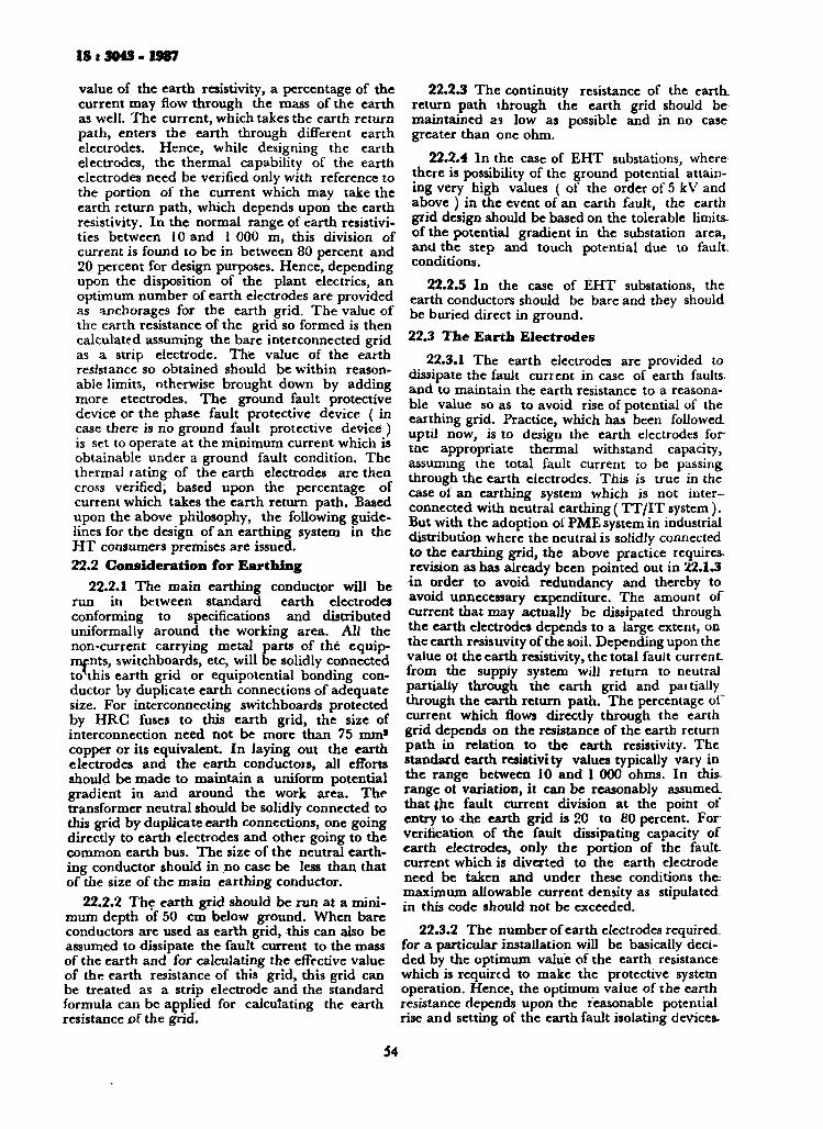
IS t 3043 - 1987
value of the earth resistivity, a percentage of the current may flow through the mass of the earth as well. The current, which takes the earth return path, enters the earth through different earth electrodes. Hence, while designing the earth electrodes, the thermal capability of the earth electrodes need be verified only with reference to the portion of the current which may take the earth return path, which depends upon the earth resistivity. In the normal range of earth resistivities between 10 and 1 000 m, this division of current is found to be in between 80 percent and 20 percent for design purposes. Hence, depending upon the disposition of the plant electrics, an optimum number of earth electrodes are provided as anchorages for the earth grid. The value of the earth resistance of the grid so formed is then calculated assuming the bare interconnected grid as a strip electrode. The value of the earth resistance so obtained should be within reasonable limits, otherwise brought down by adding more etectrodes. The ground fault protective device or the phase fault protective device ( in case there is no ground fault protective device ) is set to operate at the minimum current which is obtainable under a ground fault condition. The thermal rating of the earth electrodes are then cross verified, based upon the percentage of current which takes the earth return path. Based upon the above philosophy, the following guidelines for the design of an earthing system in the H T consumers premises are issued. 22.2 Consideration for Earthing
22.2.1 The main earthing conductor will be run in between standard earth electrodes conforming to specifications and distributed uniformally around the working area. All the non-current carrying metal parts of the equipments, switchboards, etc, will be solidly connected tonhis earth grid or equipotential bonding conductor by duplicate earth connections of adequate size. For interconnecting switchboards protected by HRC fuses to this earth grid, the size of interconnection need not be more than 75 mm* copper or its equivalent. In laying out the earth electrodes and the earth conductors, all efforts should be made to maintain a uniform potential gradient in and around the work area. The transformer neutral should be solidly connected to this grid by duplicate earth connections, one going directly to earth electrodes and other going to the common earth bus. The size of the neutral earthing conductor should in no case be less than that of the size of the main earthing conductor.
22.2.2 The earth grid should be run at a minimum depth of 50 cm below ground. When bare conductors are used as earth grid, this can also be assumed to dissipate the fault current to the mass of the earth and for calculating the effective value of the earth resistance of this grid, this grid can be treated as a strip electrode and the standard formula can be applied for calculating the earth resistance o( the grid.
22.2.3 The continuity resistance of the earth. return path through the earth grid should be maintained as low as possible and in no case greater than one ohm.
22.2.4 In the case of EHT substations, where there is possibility of the ground potential attaining very high values ( of the order of 5 kV and above ) in the event of an earth fault, the earth grid design should be based on the tolerable limits-of the potential gradient in the substation area, and the step and touch potential due to fault conditions.
22.2.5 In die case of EHT substations, the earth conductors should be bare and they should be buried direct in ground. 22.3 The Ea r th Electrodes
22.3.1 The earth electrodes are provided to dissipate the fault current in case of earth faults-and to maintain the earth resistance to a reasonable value so as to avoid rise of potential of the earthing grid. Practice, which has been followed uptil now, is to design the earth electrodes for the appropriate thermal withstand capacity, assuming the total fault current to be passing through the earth electrodes. This is true in the case ol an earthing system which is not interconnected with neutral earthing (TT/ IT system). But with the adoption ol PME system in industrial distribution where the neutral is solidly connected to the earthing grid, the above practice requires. revision as has already been pointed out in 22.1.3 -in order to avoid redundancy and thereby to avoid unnecessary expenditure. The amount of current that may actually be dissipated through. the earth electrodes depends to a large extent, on the earth resistivity of the soil. Depending upon the value ol the earth resistivity, the total fault current from the supply system will return to neutral partially through the earth grid and paitially through the earth return path. The percentage of current which flows directly through the earth grid depends on the resistance of the earth return path in relation to the earth resistivity. The standard earth resistivity values typically vary in the range between 10 and 1 000 ohms. In this range ot variation, it can be reasonably assumed. that {he fault current division at the point of entry to the earth grid is 20 to 80 percent. For verification of the fault dissipating capacity of earth electrodes, only the portion of the fault current which is diverted to the earth electrode need be taken and under these conditions the. maximum allowable current density as stipulated in this code should not be exceeded.
22.3.2 The number of earth electrodes required for a particular installation will be basically decided by the optimum value of the earth resistance which is required to make the protective system operation. Hence, the optimum value of the earth resistance depends upon the reasonable potential rise and setting of the earth fault isolating devices-
54
IS t 3043 • 1987
or the series protective devices in case where there is no ground fault detecting devices. The main criterion is that the value of the earth return resistance should not be so high as not to produce the required ground fault current for actuating the protective devices within the stipulated time. Or in other words, the optimum value of the earth resistance is closely related to setting of the earth fault protective devices used in the system. For a small installation, as a general rule, in the event of a direct earth fault the earth fault current produced should not be less than five times the highest rating of the maximum protective fuses or the setting of the earth fault relay if such a device is provided. 22.4 Determination of Earth Resistivity — As has already been pointed out, the value of the earth resistivity plays an important role in the design of the earth electrodes. In the conventional method, the earth resistivity which is to be applied in the design calculations is taken as the arithmetic mean of a number of measured values in the area under consideration. The figure so obtained seldom projects a realistic value. A more scientific approach is to measure the earth resistivity in different radial directions from a central point which may be taken as the proposed load centre. With the values so obtained, a polar curve is drawn. The polar curve is converted to an equivalent circle (see 36.6) . The radius of the circle is taken to be the average value of the earth resistivity figure which is to be applied in design calculations. Necessary allowance should, of course, be given for factors such as variations in climatic conditions, treatment of soil, etc
22.5 Design of Earth Bus
22.5.1 Design of earth bus is based upon the general guidelines given in Seetion 2. The size of the main earth grid will be decided on the basts of line to ground fault current assumed to be symmetrical short-circuit current in the system. This assumption is fairly reasonable in the case of a solidly earthed system where the ratio between XO/XI is limited to less than 3 and the ohmic value of the earth return path to the supply neutral is reasonably low. The minimum fault level existing at the supply point will be assumed to be 131 kA or the actual fault current,whichever is greater for premises at voltages above 1 kV.
22.5.2 Bare copper, PVC covered aluminium or Gl subject to relevant restrictions based on the location and nature of installation may be used as earthing to conductors. The size of the earthing conductors will be calculated according to guidelines given in the code. The time duration of the fault current as recommended is 3 seconds. According to standards developed in this regard, the size of the earthing conductors will be based upon current densities as given in Section 2 of this code. A corrosion factor of 5 percent of unit drop in the value of corrosion
index up to —10 is recommeded for steel/GI earthing conductors while designing an earthing scheme, situations of corrosion index of below - 10 should not be allowed.
22.5.3 In the case of systems where standard protective arrangments have been provided for isolating the ground faults instantaneously, due consideration can be given to this aspect in deciding upon the size of the earthing conductor by giving due allowance to lower duration of the ground fault currents.
22.6 Correlation Between Grounding and Earth Fault Protection
22.6.1 The phase fault protective device normally used in systems operating at 415 V afford reasonable protection against arcing ground faults. The ground fault current depends upon the impedance to zero sequence current flows and depends to a large extent on the grounding network and the earth resistivity. The pick up value of the ground fault relays or the value of the phase fault protective device should be coordinated for the required protection for the system. In case the impedance of the earth return path for ground fault current cannot be regulated so as to produce adequte fault current for operating the phase fault protective devices like fuses, such circuits should be protected by separate ground fault protective devices. Hence, the necessity of separate ground fault protection depends on the grounding network and its effective impedance and earth grid design is closely related to the effectiveness of the phase fault protective device in clearing a ground fault in place where separate ground fault protective devices are not provided.
22.7 Grounding and Ground Fault Protection
22.7.1 In recent, years, there has been an increasing interest in the use of ground fault protection in industrial distribution circuits. This interest has been brought about by a disturbing number of electric failures. Hence it is worthwhile to explore the need for better ground fault protection and to examine the grounding practices in the light of the required protection.
22*7.2 Distribution circuits which are solidly grounded or grounded through low impedances require fast clearing of ground faults. This involves high sensitivity in detecting low groud fault currents as wall as the co-ordination between main and feeder circuit protective devices. Fault clearing must be extremely fast where arcing is present.
22.7.3 The appeal of effective ground fault protection is based on the following:
1) The majority of electric faults involve ground. Ungrounded systems are also sub-
55

IS t 3043 - 1987
ject to ground faults and require careful attention to ground fault detection and ground fault protections.
2) T h e ground fault protective sensitivity can be relatively independent of continuous load current values and thereby have lower pick up settings than phase protective devices.
3) Ground fault currents are not transferred through system, in the case of power transformers which are connected delta-star, delta-delta. T h e ground fault protection for each system voltage level should be independent of the protection at other voltage levels. This permits much faster relaying than can be afforded by phase protective device which require co-ordinate using pick up values and time delays which extend from the load to the service generators, often resulting in considerable time delay a t some parts in the system.
4) Arcing ground faults which are not promptly detected and cleared can be extremely destructive. A relatively small investment can provide very valuable protections.
22.8 Much of the present emphasis on ground fault protection centres around or circuits below 550 V. Protective devices have usually fuse switches of circuit breakers with integrally mounted phase tr ipping devices. These protective elements are termed as overload or fault overcurr-ent devices because they carry the current in each phase and clear the circuit only when the current reaches a magnitude greater than full load current. T o accommodate inrush currents such as motor starting or transformer magnetising inrush', phase over current devices are designed with inverse characteristics, which are rather slow at overcurrent values upto about 5 times ra t ing. For
23. E A R T H I N G IN STANDBY A N D O T H E R P R I V A T E GENERATING PLANTS ( I N C L U D I N G PORTABLE A N D M O B I L E G E N E R A T O R S )
23.1 Genera l — T h e ear thing of standby and other private generat ing plant is necessary to protect against indirect contact tha t may result in electric shock. T h e objective is to create a zone in which voltage between exposed conductive parts and extraneous conductive parts are minimized in the event of an earth fault.
In this section the requirement is met by connecting the generating set frame(s), metallic cable sheaths and armouring, and all exposed conductive parts to an earthing conductor, and by connecting the system to ear th ( normally at one point only ).
example, a 1 600 A circuit breaker with conventional phase protection will clear a 3 200 A fault in about 100 seconds. Although it can be adjusted in the range ot 30 to 200 seconds, at this fault value. A 1 600 A fuse may require 10 minutes or more to clear the same 3 200 A fault. These low values of fault currents are associated predominantly with fault to ground and have generally received little attention in the design of earthing systems, until the occurrence oi many serious electric failures in recent years. In contrast, on grounded systems of 3-3 kV and above, it has been a s tandard practice to apply some form of ground fault protection.
22.9 T h e action initiated by ground fault sensing devices will vary depending upon the installation. In some cases, such as services to dwelling, it may be necessary to i m m e d i a t e l y disconnect the faulted circuit to prevent loss of life and property. However, the opening of some circuits in critical applications may in itself, endanger life or property. Therefore, each particular application should be studied carefully before selecting the action to be initiated by the ground fault protective devices.
22.10 P r o t e c t i o n A g a i n s t Arc ing Ground F a u l t s a n d E a r t h L e a k a g e
22.10.1 Necessity of arcing ground fault protection especially for 415 V installations is not very well understood and protective schemes suggested for normal industrial installations never give much importance to this aspect. I t is also seen that the fact that a series protective device like breaker or a fuse does not offer protection against an earth fault or arcing ground fault in a 415 V system, is very often forgotten. In the case of such installations, the avoidance of arcing ground faults is important from the point of view of personal safety and equipment damage.
Except in some special applications, there is, in every case, need for an independent earth electrode for energy source ear thing at the premises where the generator is located. ( Any suppliers' protective ear th terminal at the premises should also be connected to the independent earth electrode ).
The re are many variations in system design and for any particular application, the precise method of energy source earthing is subject to the recommendations of the machine manufacturers, the system parameters and, where mains supplies are also involved, the agreement of the concerned supply authority.
I t may, however, be noted that the guidance included in this section, applies to stock protection as well as protection of equipment.
SECTION 6 STANDBY AND OTHER PRIVATE GENERATING PLANTS
56

IS : 3043 - 1987
23.2 Low Voltage Up to 1 000 V Generators 23.2.1 Earth Electrodes — The overall resistance
to earth of the electrodes forming the connection to the general mass of earth from the low voltage energy source has to be consistent with the earth fault protection provided and shall be as lovv as possible.
23.2.2 Single Low Voltage ( Synchronous Machines )
Generator Earthing
23.2.2.1 Generator operating in isolation {from the mains or other supplies ) — In this basic arrangement, the generator neutral point should- be connected to the neutral of the low voltage switchgear which is itself connected through a bolted link ( for test purposes ) to an earthing conductor and the independent earth electrode.
23.2.2.2 Standby generator ( without paralleling facility ) — In addition to the earthing requirements stated for a set operating in isolation from other supplies, special attention needs to be given to the change-over, arrangement for standby set, which has to ensure that there can be no inadvertent parallel connection ( see Fig. 24 ).
In general four-pole changeover switching between the mains and standby, supplies should be used to provide isolation of the generator and electricity board neutral earths. However, in the case of a protective multiple earthing ( PME ) supply, three- or four-pole switching may be used.
23.2.2.3 Standby generator ( capable of parallel operation with incoming mains supply ) — Electricity boards will not generally permit continuous parallel operation of a synchronous machine with the low voltage mains supply, unless there are no other consumers on the network. However, short-term parallel operation for no-break load transfer or testing may be permitted. Also, if a synchronus machine output is rectified and connected through a mains modulated static inverter continuous parallel operation will usually be permitted. In the latter case, the generator neutral terminal should be connected to the independent earth electrode and to any electricity board earth.
For short-term parallel operation, giving no-break load transfer, the alternative energy source earthing arrangements, which may be used, are as described in 23.2.3.1, except that only one generating set is involved.
PRIME MOVER
CHANGEOVER FACILITY (AUTOMATIC OR MANUAL)
INCOMING ELEC BOARD
Y
EX CO PA :TRANEOUS| I NOUCTIVE r RTS i.-h-X-h EARTHING BAR
INDEPENDENT EARTH ELECTRO0E
N O T E 1 — Cable sheath earth of provided/shown
NOTE 2 — PNE link of provided/shown
NOTE 3 — Changeover switch could be 3-pole with linked neutral.
FIG. 24 SINGLE LOW VOLTAGE STANDBY GENERATOR ( WITHOUT PARELLELING FACILITY )
57
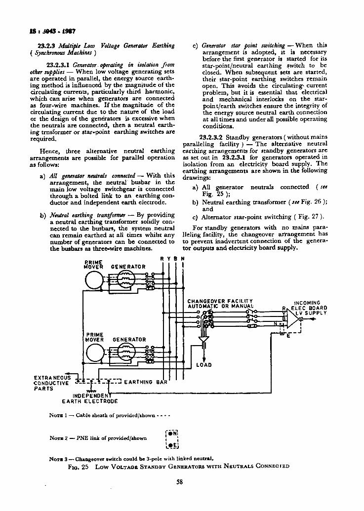
IS i 3043 - 1987
23.2.3 Multiple Low ( Synchronous Machines )
Voltage Generator Earthing
23.2.3.1 Generator. operating in isolation from other supplies — When low voltage generating sets are operated in parallel, the energy source earthing method is influenced by the magnitude of the circulating currents, particularly third harmonic, which can arise when generators are connected as four-wire machines. If the magnitude of the circulating current due to the nature of the load or the design of the generators is excessive when the neutrals are connected, then a neutral earthing trnsformer or star-point earthing switches are required.
Hence, Lhree alternative neutral earthing arrangements are possible for parallel operation as follows:
a) All generator neutrals connected — With this arrangement, the neutral busbar in the main low voltage switchgear is connected through a bolted link to an earthing conductor and independent earth electrode.
b) Neutral earthing transformer — By providing a neutral earthing transformer solidly connected to the busbars, the system neutral can remain earthed at all times whilst any number of generators can be connected to the busbars as three-wire machines.
PRIME MOVER GENERATOR
PRIME MOVER
EXTRANEOUS J. CONDUCTIVE *--PARTS INDEPENDENT
EARTH ELECTRODE
c) Generator star point switching — When this arrangement is adopted, it is necessary before the first generator is started for its star-point/neutral earthing switch to be closed. When subsequent sets are started, their star-point earthing switches remain open. This avoids the circulating* current problem, but it is essential that electrical and mechanical interlocks on the star-point/earth switches ensure the integrity of the energy source neutral earth connection at all times and under all possible operating conditions.
23.2.3.2 Standby generators (without mains paralleling facility ) — The alternative neutral earthing arrangements for standby generators are as set out in 23.2.3.1 for generators operated in isolation from an electricity board supply. The earthing arrangements are shown in the following drawings:
a) All generator neutrals connected (see Fig. 25 );
b) Neutral earthing transformer (seeFig. 26 ); and
c) Alternator star-point switching ( Fig. 27). For standby generators with no mains para
lleling facility, the changeover arrangement has to prevent inadvertent connection of the generator outputs and electricity board supply.
R Y B N
CHANGEOVER FACILITY AUTOMATIC OR MANUAL
-o &£> o>o-INCOMING
ELEC BOARD LV SUPPLY
NOTE 1 — Cable sheath of provided/shown •
Nora 2 — PNE link of provided/shown IN!
LfEJ
NOTB 3 — Changeover switch could be 3-pole with linked neutral. FIG. 25 Low VOLTAGE STANDBY GENERATORS WITH NEUTRALS GONNECIED
58

IS < 3043 . 1987
EXTRANEOUS CONDUCTIVE PARTS
NEUTRAL EARTHING TRANSFORMER
PRIME MOVER INCOMING ELEC
BOARD LV SUPPLY
INDEPENDENT FARTH ELECTRODE
NOTE 1 — Cable sheath earth of provided/shown ■
Nora 2 — PNE link of provided/shown r r j i ONi i >
Nora 3 — If a bus section switch is installed a neutral earthing transformer will be required on each section of busbar.
FIG. 26 Low VOLTAGE STANDBV GENERATORS WITH NEUTRAL EARTHING TRANSFORMERS
In general, four-pole changeover switching between the electricity board supply and the standby supply should be used to provide isolation of the neutral earths. However, in the case of a protective multiple earthing ( P M E ) electricity board supply, three- or four-pole switching may be used.
23.2.3.3 Standby generators ( capable of parallel operation with the incoming mains supply ) — The conditions for which parallel operation of multiple generating set installations with the mains supply may be permitted by the electricity board are the same as apply for single generators (see 23.2.2.3 ).
The possible alternative energy source earthing arrangements are as listed in 23.2.3.2.
23.2.4 Single and Multiple Generator Earthing ( Synchronous Machines ) — The parallel operation of synchronous machines is generally permitted; such machines are normally provided where the prime mover is driven by wind, water or biochemical plant, but may be provided with any prime mover. Any neutral point of such machine windings should be earthed, but the machine framework and any other extraneous metalwork should be connected to the electricity board earth terminal, if provided.
23.2.5 Small Portable Low Voltage Generators upto 5 kVA in Rating — Where portable generators are used to provide a supply and earthing is considered as a means of protection against electric shock, they are required to be connected as follows:
a) Single-phase machines should have either a centre tap on the winding connected to earth or, if not compatible with the system, one end connected to earth and designated the neutral. The Centre tap method reduces the effective line-earth voltage and is particularly used where the generator is to feed 110 V portable tools; and
b) Three-phase machines should have their windings connected in star, with the star connection made available and connected to earth.
In all cases, the exposed metalwork of the generator should be adequately connected to the earth terminal, preferably with a bolted connection.
The earth electrode should have a minimum cross-section area if it is not protected against corrosion of 25 mm* for copper and 50 mm* for steel. Whilst there is no minimum value of earth
59
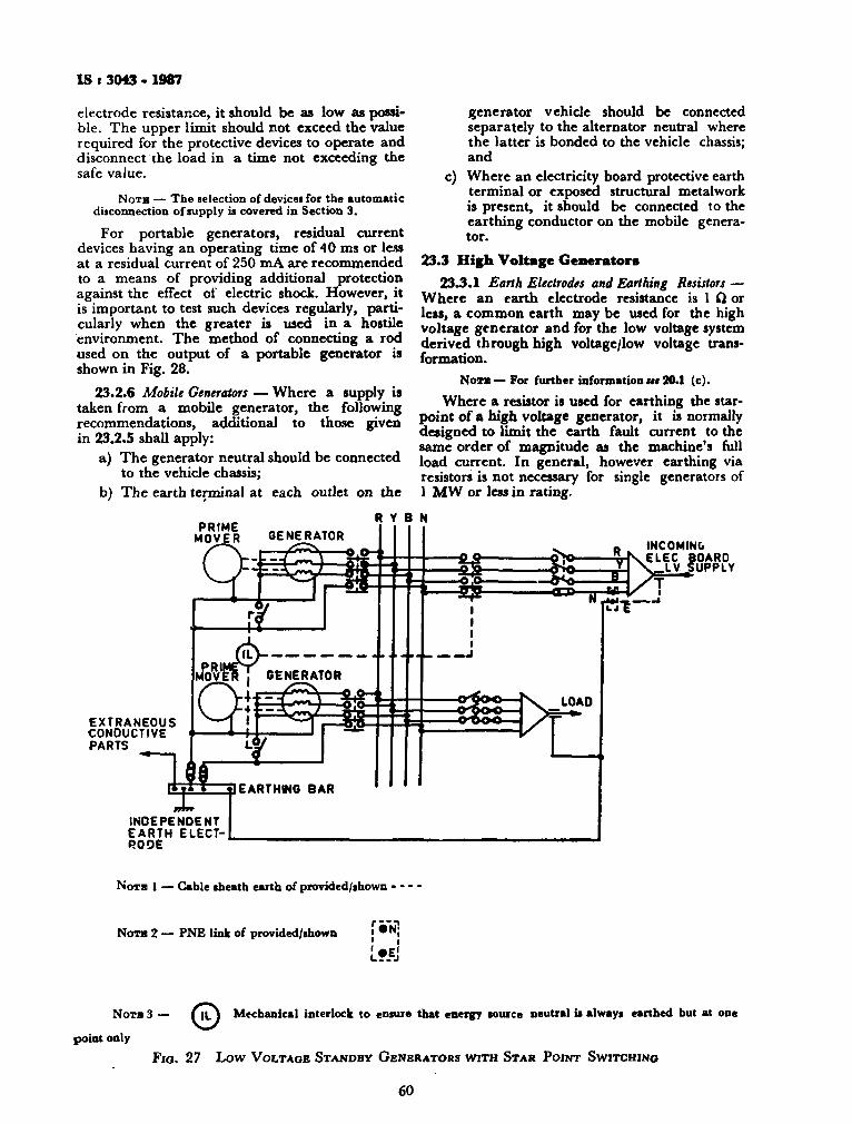
IS t 3043 - 1987
electrode resistance, it should be as low as possible. The upper limit should not exceed the value required for the protective devices to operate and disconnect the load in a time not exceeding the safe value.
NOTB — The selection of devices for the automatic disconnection of supply is covered in Section 3. For portable generators, residual current
devices having an operating time of 40 ms or less at a residual current of 250 mA are recommended to a means of providing additional protection against the effect of electric shock. However, it is important to test such devices regularly, particularly when the greater is used in a hostile environment. The method of connecting a rod used on the output of a portable generator is shown in Fig. 28.
23.2.6 Mobile Generators — Where a supply is taken from a mobile generator, the following recommendations, additional to those given in 23.2.5 shall apply:
a) The generator neutral should be connected to the vehicle chassis;
b) The earth terminal at each outlet on the
generator vehicle should be connected separately to the alternator neutral where the latter is bonded to the vehicle chassis; and
c) Where an electricity board protective earth terminal or exposed structural metalwork is present, it should be connected to the earthing conductor on the mobile generator.
23.3 High Voltage Generators 23.3.1 Earth Electrodes and Earthing Resistors —
Where an earth electrode resistance is 1 Q or less, a common earth may be used for the high voltage generator and for the low voltage system derived through high voltage/low voltage transformation.
Nora— For further information u$ 20.1 (c). Where a resistor is used for earthing the star-
point of a high voltage generator, it is normally designed to limit the earth fault current to the same order of magnitude as the machine's full load current. In general, however earthing via resistors is not necessary for single generators of 1 MW or less in rating.
PRIME MOVER
R Y 8 N GENERATOR
EXTRANEOUS CONDUCTIVE PARTS
PRIfc © - - ■ M O V E R , GENERATOR
INCOMING EC BOA _ LV SUPPLY ELEC B0AR0
su—
^>f INDEPENDENT EARTH ELECTRODE
NOTB 1 — Cable sheath earth of provided/shown
NOTB 2 — PNE link of provided/shown i * N ;
L?.fcJ
NOTB 3 — ( i t ) Mechanical interlock to ensure that energy source neutral is always earthed but at one
point only FIG. 27 Low VOLTAGE STANDBY GENERATORS WITH STAR POINT SWITCHING
60
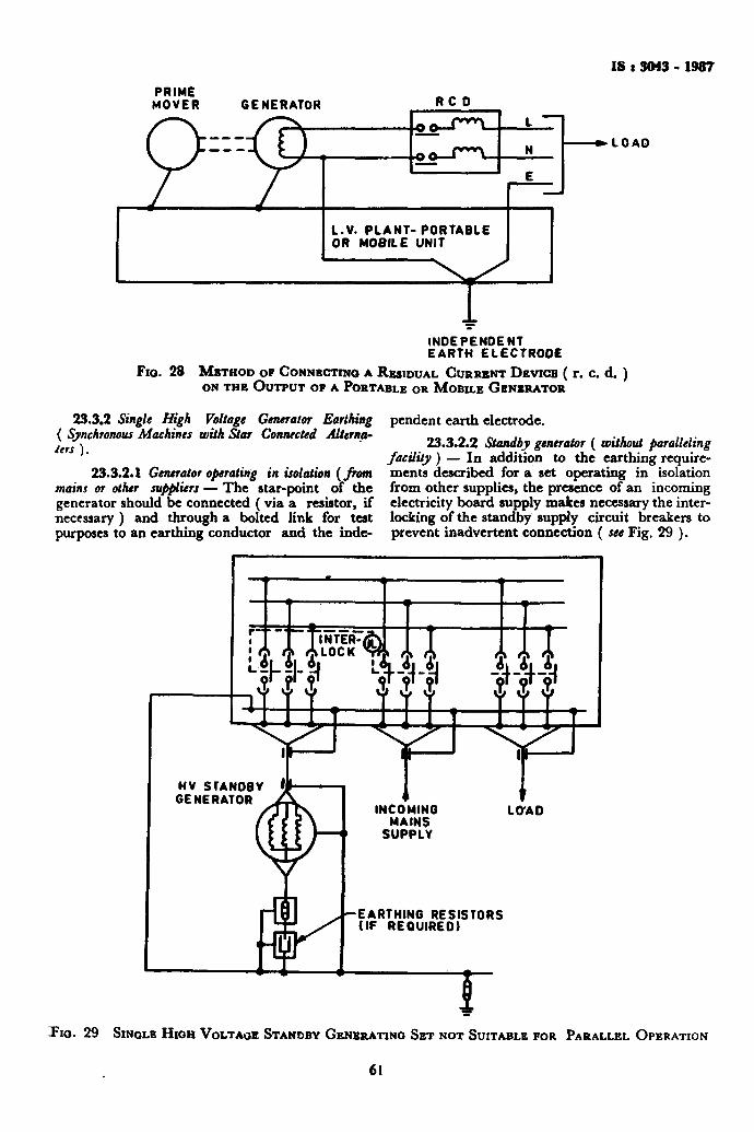
IS t 3043 - 1987
PRIME MOVER GENERATOR RC 0
o-T^. oo-
L.V. PLANT- PORTABLE OR MOBILE UNIT
LOAD
Fio.
INDEPENDENT EARTH ELECTRODE
28 METHOD OP CONNECTING A RESIDUAL CURRENT DEVIOB ( r. c. ON THE OUTPUT OP A PORTABLE OR MOBILE GENERATOR
d . )
23.3.2 Single High Voltage Generator Earthing ( Synchronous Machines with Star Connected Alterna-Urs ) .
23.3.2.1 Generator operating in isolation {from mains or other suppliers — The star-point of the generator should be connected ( via a resistor, if necessary ) and through a bolted link for test purposes to an earthing conductor and the inde
pendent earth electrode. 23.3.2.2 Standby generator ( without paralleling
facility ) — In addition to the earthing requirements described for a set operating in isolation from other supplies, the presence of an incoming electricity board supply makes necessary the interlocking of the standby supply circuit breakers to prevent inadvertent connection ( see Fig. 29 ).
• X X ALOCK'^SI i X I I I L*L*L4J ikJti.h AAA X X X
PIG. 29 SINGLE HIGH VOLTAGE STANDBY GENERATING SET NOT SUITABLE FOR PARALLEL OPERATION
61
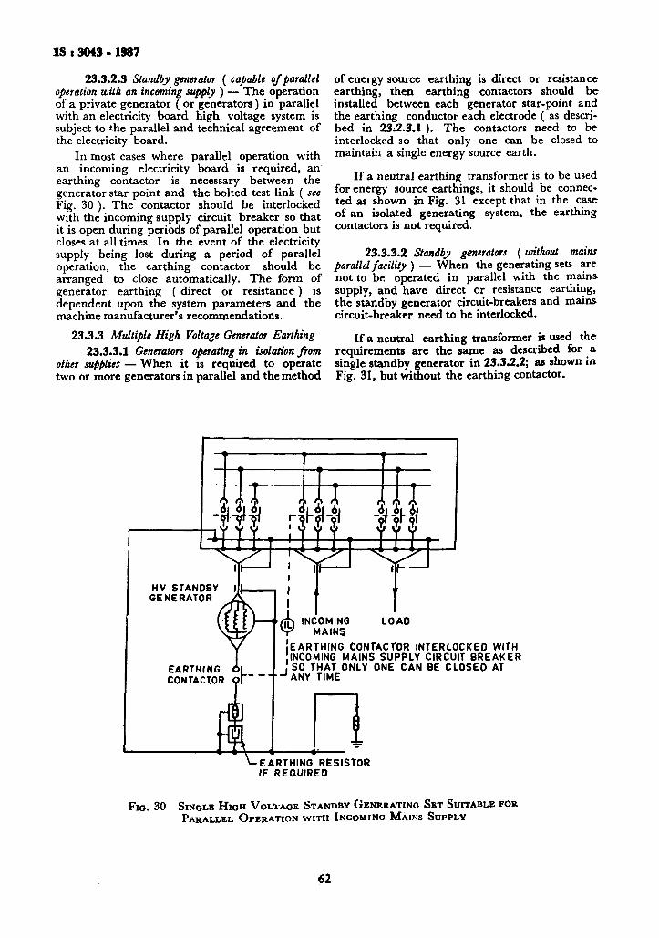
I S t 3043 • 1987
23.3.2.3 Standby generator ( capable of parallel operation with an incoming supply ) — The operation of a private generator ( or generators) in parallel with an electricity board high voltage system is subject to the parallel and technical agreement of the electricity board.
In most cases where parallel operation with an incoming electricity board is required, an earthing contactor is necessary between the generator star point and the bolted test link ( see Fig. 30 ). The contactor should be interlocked with the incoming supply circuit breaker so that it is open during periods of parallel operation but closes at all times. In the event of the electricity supply being lost during a period of parallel operation, the earthing contactor should be arranged to close automatically. The form of generator earthing ( direct or resistance) is dependent upon the system parameters and the machine manufacturer's recommendations.
23.3.3 Multiple High Voltage Generator Earthing 23.3.3.1 Generators operating in isolation from
other supplies — When it is required to operate two or more generators in parallel and the method
of energy source earthing is direct or resistance earthing, then earthing contactors should be installed between each generator star-point and the earthing conductor each electrode ( as described in 23*2.3.1 ). The contactors need to be interlocked so that only one can be closed to maintain a single energy source earth.
If a neutral earthing transformer is to be used for energy source earthings, it should be connected as shown in Fig. 31 except that in the case of an isolated generating system, the earthing contactors is not required.
23.3.3.2 Standby generators (witkout mains parallel facility ) — When the generating sets are not to be operated in parallel with the mains supply, and have direct or resistance earthing, the standby generator circuit-breakers and mains circuit-breaker need to be interlocked.
If a neutral earthing transformer is used the requirements are the same as described for a single standby generator in 23.3.2.2; as shown in Fig. 31, but without the earthing contactor.
HV STANDBY GENERATOR
EARTHING CONTACTOR 'ANY TIME
LOAD
EARTHING CONTACTOR INTERLOCKED WITH INCOMING MAINS SUPPLY CIRCUIT BREAKER SO THAT ONLY ONE CAN BE CLOSED AT
EARTHING RESISTOR IF REQUIRED
Fio. 30 SINGLE HIGH VOLIAOE STANDBY GENERATING SET SUITABLE FOR PARALLEL OPERATION WITH INCOMING MAINS SUPPLY
62
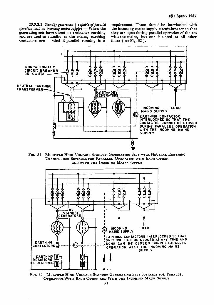
18 s 3043-1987
23.3.3.3 Standby generators ( capable of parallel operation with an incoming mains supply) — When the generating sets have direct or resistance earthing and are used as standby to the mains, earthing contactors are ^ded if parallel running is a
requirement. These should be interlocked with the incoming mains supply circuit-breaker so that they are open during parallel operation of the set with the mains, but one is closed at all other times ( see Fig. 32 ).
NON -AUTOMATIC CIRCUIT BREAKER OR SWITCH
NEUTRAL EARTHING TRANSFORMER-
I S ffl$ Hi ft Uli tUi nJi i uli ly
I INCOMING ± MAINS SUPPLY
LOAD
Flo.
EARTHING CONTACTOR INTERLOCKED SO THAT THE
! CONTACTOR CANNOT BE CLOSED ' DURING PARALLEL OPERATION
WITH THE INCOMING MAINS SUPPLY
31 MULTIPLE HIGH VOLTAGE STANDBY GENERATING SETS WITH NEUTRAL EARTHING TRANSFORMER SUITABLE FOR PARALLEL OPERATION WITH EACH OTHER
AND WITH THE INCOMING MAINS SUPPLY
EARTHING 0i CONTACTORS o|"
EARTHING RESISTORS
[IF REQUIRED^
■-©-a-
LOAD
'EARTHING CONTACTORS INTERLOCKED SO THAT ONLY ONE CAN BE CLOSED AT ANY TIME AND
.iNONE CAN BE CLOSED DURING PARALLEL OPERATION WITH THE INCOMING MAINS
SUPPLY
LC Fia. 32 MULTIPLE HIGH VOLTAGE STANDBY GENERATING SETS SUITABLE FOR PARALLEL
OPBRATIOIOVITH EACH OTHER AND WITH THE INCOMING MAINS SUPPLY
63
IS i 3043 • 1987
SECTION 7 MEDICAL ESTABLISHMENTS
24. PROTECTIVE M E A S U R E S T H R O U G H EARTHING I N MEDICAL ESTABLISHM E N T S
24.0 General — In the context of this Section "installation", means any combination of interconnected electrical equipment within a given space or location intended to supply power to electrical equipment used in medical practice.
24.0.1 For the purposes of this Section, reference may also be made to SP : 30 ( Part 3/ Sec 4 )- l985*.
24.0.2 As such, some parts of the installation may be present in the patient 's environment, where potential differences, that could lead to excessive currents through the patient, must be avoided. For this purpose a combination or earthing of equipment and potential equalization in the installation seems to provide the best solution. A disadvantage of such a system is that in the case of an insulation fault in circuits directly connected to supply mains, the fault current may cause a considerable voltage drop over the protective earth conductor of the relevant circuit. Since a reduction of such a voltage drop by the application of increased cross-sectional areas of protective conductors is usually impractical, available solutions are the reduction of the duration of fault currents to earth by special devices or the application of a power supply which is isolated from earth.
24.0.3 Generally a power supply system including a separated protective conductor is required. ( TN-S System ) in medical establishment ( see 6.1.1 ).
In addition the following provisions may be required, depending upon the nature of the examinations or treatments performed:
a) Additional requirements concerning protective conductors and protective devices to restrict continuous voltage differences.
b) Restriction of voltage differences by supplementary equipotential bonding. During the application of equipment with direct contact to the patient, at least a potential equalized zone around the patient shall be provided with a patient centre bonding bar to which the protective and functional earth conductors of the equipment are connected. All accessible extraneous conductive parts in the zone shall be connected to this potential equalization bar.
c) Restriction of the potential equalization zone around one patient, meaning practically around one operation table or around one bed in an intensive care room.
d) If more than one patient is present in an area, connection of the various potent ia l equalization centres to a central potential equalization busher, which should preferably be connected to the protective earth system of the power supply for the given area. In its completed form, the equipotential bonding network may consist partly of fixed and permanently installed bonding and partly of a number of separate bondings which are made when the equipment is set up near the patient. T h e necessary terminals for these bonding connection should be present on equipment and in t h e installation.
e) Restriction of the duration of transient voltage difference by the application of residual current operated protective devices ( earth leakage circuit-breakers ).
f) Continuity of power supply to certain equipment in the case of a first insulation fault to earth and restriction of transient voltage differences by application of isolating transformers.
g) Monitoring of first insulation fault to earth in an I T Systems ( see 6.1.1 ) ( the secon dary side of an isolating transformer ) with sufficiently high impedance to ear th .
NOTE—Additional safety measures are required besides earthing described in this Section. These cover fire safety, safety supply systems and interference suppression. Reference may be made to-NEC (Par t 3, Section 4 ) * .
24.1 Safety P r o v i s i o n s 24.1.1 Safety measures from the point of view
of earthing are divided into a number of provisions as given in Table 10.
24.1.2 Provision Po shall be applicable to all buildings containing medically used rooms. Provision PI shall be applicable for all medically used rooms.
Other requirements of this Section, need no t be complied with, if:
a) a room is not intended for the use of medical electrical equipment, or
b) patients do not come intentionally in contact with medical electrical equipment during diagnosis or treatment, or
c) only medical electrical equipment is used which is internally powered or of protection Class I I .
The rooms mentioned under (a), (b) and (c) may be, for example, massage rooms, general wards, doctor's examining room (office, consulting room), where medical electrical equipment is no t used.
♦National Electrical Code. •National Electrical Code.
64
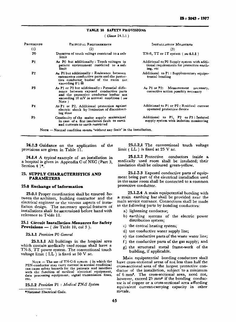
18:3043-19*7
TABLE 10 SAFETY PROVISIONS
( Clause 24.1.1 )
PROVISIONS PRINCIPAL R E Q U I R E M E N T S
(1) (2) PO Duration of touch voltage restricted to a safe
limit Pi As PO but additionally : Touch voltages in
patient environment restricted to a safe limit
P2 As PI but additionally : Resistance between extraneous conductive parts and the protective conductor busbar of the room not exceeding O ' l f l
As PI or P2 but additionally: Potential difference between exposed conductive parts and the protective conductor busbar not exceeding 10 mV in normal condition ( see Note )
As PI or P2. Additional protection against electric shock by limitation of disconnecting t ime
Continuity of the mains supply maintained in case of a first insulation fault to earth and currents to earth restricted
P3
P4
P5
INSTALLATION M E A S U R E S
(3) TN-S, T T or I T system ( see 6.1.1 )
Additional to PO Supply system with additional requirements for protective earthing, etc
Additional to PI : Supplementary equipo-tential bonding
As PI or P2: Measurement necessary, corrective action possibly necessary
Additional to PI or P2 : Residual current operated protective device
Additional to P I , P2 or P3 : Isolated supply system with isolation monitoring
N O T E — Normal condition means 'without any fault' in the installation.
24.1.3 Guidance on the application of the provisions are given in Table 11.
24.1.4 A typical example of an installation in a hospital is given in Appendix C of NEC (Part 3, Section 4 )*.
25. SUPPLY CHARACTERISTICS AND PARAMETERS
25.0 Exchange of Information
25.0.1 Proper coordination shall be ensured between the architect, building contractor and the electrical engineer or the various aspects of installation design. The necessary special features of installations shall be ascertained before hand with reference to Table 11.
25.1 Circuit Installation Measures for Safety Provisions — ( See Table 10, col 3 ).
25.1.1 Provision P0 General 25.1.1.1 All buildings in the hospital area
which contain medically used rooms shall have a TN-S, TT power system. The conventional touch voltage limit ( LL ) is fixed at 50 V ac.
N O T E — The use of TN-C-S system ( in which the PEN-conductor may carry current in normal condition) can cause safety hazards for the patients and interfere with the function of medical electrical equipment, data processing equipment, signal transmission lines, etc.
25.1.2 Provision PI : Medical TN-S System
'Nat ional Electrical Code.
25.1.2.1 The conventional touch voltage limit ( LL ) is fixed at 25 V ac.
25.1.2.2 Protective conductors inside a medically used room shall be insulated; their insulation shall be coloured green-yellow.
25.1.2.3 Exposed conductive parts of equipment being part of the electrical installation used in the same room shall be connected to a common protective conductor.
25.1.2.4 A main equipotential bonding with a main earthing bar shall be provided near the main service entrance. Connections shall be made to the following parts by bonding conductors:
a) lightening conductor; b) earthing systems of the electric power
distribution system; c) the central heating system; d) tne conductive water supply line; e) the conductive parts of the waste water line; f) the conductive parts of the gas supply; and g) the structural metal frame-work of the
building, if applicable. Main equipotential bonding conductors shall
have cross-sectional areas of not less than half the cross-sectional area of the largest protective conductor of the installation, subject to a minimum of 6 mm*. The cross-sectional area, need not, however, exceed 25 mm* if the bonding conductor is of copper or a cross-sectional area affording equivalent current-carrying capacity in other metals.
65
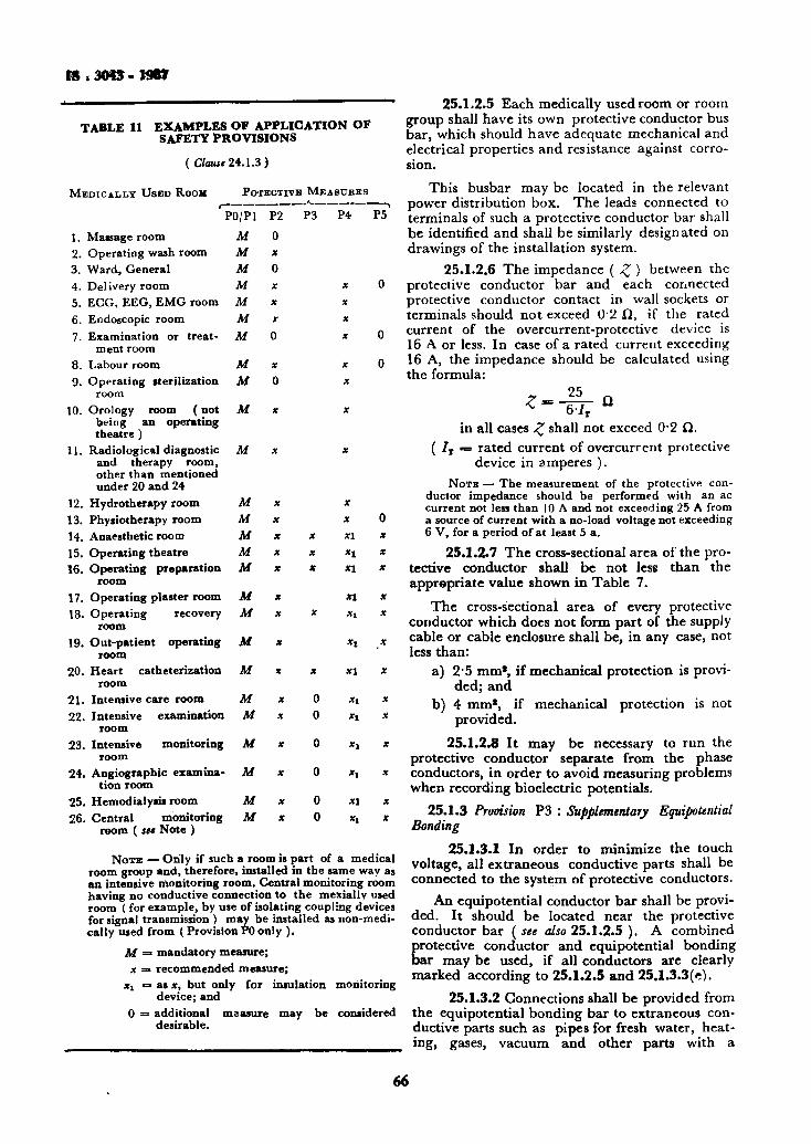
is ,3043-wet
TABLE 11 EXAMPLES OF APPLICATION OF SAFETY PROVISIONS
( C/<uo«24.1.3)
MEDICALLY U S E D ROOM
r
1. Massage room 2. Operating wash room 3. Ward, General 4. Delivery room 5. ECG, EEG, EMG room 6. Endoscopic room 7. Examination or treat
ment room 8. Labour room 9. Operating sterilization
room 10. Orology room (not
being an operating theatre )
11. Radiological diagnostic and therapy room, other than mentioned under 20 and 24
12. Hydrotherapy room 13. Physiotherapy room 14. Anaesthetic room 15. Operating theatre 16. Operating preparation
room 17. Operating plaster room 18. Operating recovery
room
POTEOTITB M E A
PO/Pl
At M At M M M M
M At
M
M
M M At M M
M M
P2 0 X 0 X X
X
0
X 0
X
X
X X X X X
X X
P3
X X X
X
SURES
P4
X X X
X
X X
X
X
X X XI
* 1 XI
XI
Xl
P5
19. Out-patient operating At x xx room
20. Heart catheterization At x x x\ room
21. Intensive care room At x 0 xj 22. Intensive examination At x 0 Xi
room 23. Intensive monitoring At x 0 xt
room 24. Angiographic examina- At x 0 xt
tion room 25. Hemodialysis room At x 0 xi 26. Central monitoring At x 0 xt
room ( jet Note )
0 x x X
X
X
X
X
X
X
NOTE — Only if such a room is part of a medical room group and, therefore, installed in the same way as an intensive monitoring room. Central monitoring room having no conductive connection to the mexially used room ( for example, by use of isolating coupling devices for signal transmission ) may be installed as non-medical ly used from ( Provision PO only ).
At = mandatory measure; x = recommended measure;
X! = as x, but only for insulation monitoring device; and
0 = additional measure may be considered desirable.
25.1.2.5 Each medically used room or room group shall have its own protective conductor bus bar, which should have adequate mechanical and electrical properties and resistance against corrosion.
This busbar may be located in the relevant power distribution box. The leads connected to terminals of such a protective conductor bar shall be identified and shall be similarly designated on drawings of the installation system.
25.1.2.6 The impedance ( Z ) between the protective conductor bar and each connected protective conductor contact in wall sockets or terminals should not exceed 0 2 £1, if the rated current of the overcurrent-protective device is 16 A or less. In case of a rated current exceeding 16 A, the impedance should be calculated using the formula:
* 6 / r
in all cases % shall not exceed 0 2 ft. ( IT = rated current of overcurrent protective
device in amperes ) . NOTB — The measurement of the protective con
ductor impedance should be performed with an ac current not less than 10 A and not exceeding 25 A from a source of current with a no-load voltage not exceeding 6 V, for a period of at least 5 a.
25.1.2.7 The cross-sectional area of the protective conductor shall be not less than the appropriate value shown in Table 7.
The cross-sectionai area of every protective conductor which does not form part of the supply cable or cable enclosure shall be, in any case, not less than:
a) 2 5 mm*, if mechanical protection is provided; and
b) 4 mm*, if mechanical protection is not provided.
25.1.2.8 It may be necessary to run the protective conductor separate from the phase conductors, in order to avoid measuring problems when recording bioelectric potentials.
25.1.3 Provision P3 : Supplementary Equipotential Bonding
25.1.3.1 In order to minimize the touch voltage, all extraneous conductive parts shall be connected to the system of protective conductors.
An equipotential conductor bar shall be provided. It should be located near the protective conductor bar ( see also 25.1.2.5 ). A combined
Erotective conductor and equipotential bonding ar may be used, if all conductors are clearly
marked according to 25.1.2.5 and 25.1.3.3(c).
25.1.3.2 Connections shall be provided from the equipotential bonding bar to extraneous conductive parts such as pipes for fresh water, heating* gases, vacuum and other parts with a
66
IS ', 3043 - 19S7
conductive surface area larger than C*02 m* or a linear dimension exceeding 20 cm or smaller part that may be grasped by hand.
Additionally, the following requirements apply: a) Such connections need not be made to:
1) Extraneous conductive parts inside of walls (for example, structural metal work of buildings ) having no direct connection to any accessible conductive part inside the room, and
2) Conductive parts in a non-conductive enclosure;
b) In locations where the position of the patient can be predetermined this provision may be restricted to extraneous conductive parts within the patient environment ( see Apppendix B of NEC (Part 3, Section 4 ); and
c) In operating theatres, intensive care rooms, heart catheterization rooms and rooms intended for the recording of bioelectrical action potentials all parts should be connected to the equipotential bonding bar via direct and separate conductors.
25.1.3.3 The following requirements shall be fulfilled:
a) The impedance between extraneous conductive parts and the equipotential bonding bar shall not exceed 0 1 Q .
NOTE — The measurement of this impedance should be perfoimed with a current not less than 10 A and not exceeding 25 A during not less than 5 s from a current source with a no-load potential not exceeding 6 V ac.
b) All equipotential bonding conductors shall be insulated, the insulation being coloured green-yellow.
NOTE — Insulation of the equipotential bonding conductors is necessary, to avoid loops by contact and to avoid picking up of stray currents.
c) Equipotential conductors between permanently installed extraneous conductive parts and the equipotential bonding bar shall have a cross-sectional area of not less than 4 mm* copper or copper equivalent.
d) The equipotential bonding bar, if any, should have adequate mechanical and electrical properties, and resistance against corrossion.
e) The conductors connected to the equipotential bonding bar shall be marked and shall be similarly designated on drawings of the installation system.
f) A separate protective conductor bar and an equipotential bonding bar in a medically used room or in a room group shall be interconnected with a conductor having a cross-sectional area of not less than 16 mm1
copper or copper equivalent (see 25.1.3.1).
g) An adequate number (under consideration) of equipotential bonding terminals other than those for protective conductor contact or pins of socket outlets should be provided in each room for the connection of an additional protective conductor of equipment or for reasons of functional earthing of equipment.
25.1.4 Provision P3 : Restriction of Touch Voltage in Rooms Equipped for Direct Cardiac Application
25.1.4.1 The continuous current through a resistance of 1 000 connected between the equipotential bonding bar and any exposed conductive part as well as any extraneous conductive part in the patient environment shall not exceed 10 MA in normal condition for frequencies from dc to 1 kHz.
For a description of patient environment, see Appendix B of NEC ( Part 3, Section 4 ). Where the measuring device has an impedance and a frequency characteristics, the current may also be indicated as a continuous voltage with a limit of 10 mV between the parts mentioned above.
a) During the test, it is assumed that fixed and permanently installed medical electrical equipment is operating.
b) 'Normal conditions' means without any fault in the installation and in the medical electrical equipment.
NOTE — To comply with this requirement, it may be necessary to apply one or more of the following methods: Extraneous conductive parts may be: a) connected to the equipotential bonding bar by
a conductor of a large cross-sectional area in order to reduce the voltage drop across such a conductor,
b) insulated so that it is not possible to touch them unintentionally, and
c) provided with isolating joints at those places where they enter and leave the room.
Exposed conductive parts of permanently installed equipment may be isolated from the conductive building construction.
25.1.5 Provision P4: Application of Residual-Current Protective Devices
25.1.5.1 The use of a residual-current protective device is not recognized as a sole means of protection and does not obviate the need to apply the provisions PI and P2.
25.1.5.2 Each room or each room group shall be provided with at least one residual-current protective device.
25.1.5.3 A residual-current protective device shall have a standard rated operating residual-current / A N < 30 mA.
25.1.5.4 A medical isolating transformer and the circuits supplied from it shall not be protected by a residual current protective device.
67

I S : 3043 - 1987
25.1.5.5 Electrical equipment, for example, general lighting luminaries, installed more than 2 5 m above floor level, need not be protected by a residual-current protective device.
25.1.5.6 Fixed and permanently installed electromedical equipment with a power consumption requiring an overcurrent protective device of more than 63 A rated value may be connected to the supply mains by use of a residual-current protective device with / £\ JV ^ 300 mA.
25.1.6 Provision P5: Medical IT System 25.1.6.0 The use of a medical IT-System for
the supply of medically used room for example, operating theatres, may be desirable for different reasons:
a) A medical IT-System increases the reliability of power supply in areas where an
v interruption of power supply may cause a hazard to patient or user;
b) A medical IT-System reduces an earth fault current to a low value and thus also reduces the touch voltage across a protective conductor through which this earth fault current.may flow;
c) A medical IT-System reduces leakage currents of equipment to a low value, where the medical IT-System is approximately symmetrical to earth.
It is necessary to keep the impedance to earth of the medical IT-System as high as possible. This may be achieved by:
a) restriction of the physical dimensions of the medical isolating transformer,
b) restriction of the system supplied by this transformer,
c) restriction of the number of medical electrical equipment connected to such a system, and
d) high internal impedance to earth of the insulation monitoring device connected to such a circuit.
If the primary reason for the use of a medical IT-System is the reliability of the power supply, it is not possible to define, for such system, a hazard current and an insulation resistance monitoring device should be used.
If, on the other hand, the restriction of leakage current of equipment is the main reason for the use of the medical IT-System, an insulation impedance monitoring device should be used.
25.1.6.1 For'each room or each room group at least one fixed and permanently installed medical isolating transformer shall be provided.
25.1.6.2 A medical isolating transformer shall be protected against short-circuit and overload.
In case of a short-circuit or a double earth fault in parts of opposite polarity of the medical IT-System, the defective system shall be disconnected by the relevant overcurrent protective device.
If more than one item of equipment can be connected to the same secondary winding of the transformer, at least two separately protected circuits should be provided for reasons of continuity of supply.
25.1.6.3 Overcurrent protective devices shall be easily accessible and shall be marked to indicate the protective circuit.
25.1.6.4 An insulation monitoring device shall be provided to indicate a fault of the insulation to earth of a live part of the medical IT-System.
25.1.6.5 Fixed and permanently installed equipment with a rated power input of more than 5 kVA and all X-ray equipment ( even with a rated power input of less than 6 kVA) shall be protected by Provision P4. Electrical equipment, for example, general lighting, more than 2 5 m above floor level, may be connected directly to the supply mains.
25.1.6.6 General requirements for insulation monitoring devices — A separate insulation resistance or impedance monitoring device shall be provided for each secondary system. It shall comply with the requirements of (a) to (d) below:
a) It shall not be possible to render such a device inoperative by a switch. It shall indicate visibly and audibly if the resistance or impedance of the insulation falls below the value given in 25.1.6.7 and 23.1.6.8.
b) A test button shall be provided to enable checking the response of the monitor to a fault condition as described in 25.1.6.4.
c) The visible indication mentioned in (a) of the insulation monitoring device shall be visible in the monitored room or room group.
d) The insulation monitoring device should be ■* connected symmetrically to the secondary
circuit of the transformer.
25.1.6.7 Insulation resistance monitoring device — The ac-resistance of an insulation resistance monitoring device shall be at least 100 kQ. The measuring voltage of the monitoring device shall not exceed 25 V, and the measuring current ( in case of a short-circuit of an external conductor to earth ) shall not exceed 1 mA. The alarm shall operate if the resistance between the monitored isolated circuit and earth is 50 kQ or less, setting to a higher value is recommended.
25.1.6.8 Insulation impedance monitoring device — An insulation-impedance monitoring device shall
68
I S : 3043-1987
give reading calibrated in total hazard current with the value of 2 mA near the centre of the metre scale.
The device shall not fail to alarm for total hazard currents in excess of 2 mA. In no case, however, shall the alarm be activated until the fault hazard current exceeds 0*7 mA.
NOTE — The value of 2 mA or 0-7 mA are based on practical experience with 110 to 120 V power supplies. For a 220-240 V power supply, it may be .necessary to increase these values to 4 and 1"4 mA because of the higher leakage current of equipment.
During the checking of the response of the monitor to a fault condition the impedance between the medical IT-System and earth shall not decrease.
SECTION 8 STATIC AND LIGHTNING PROTECTION EARTHING
NOTE — For the time being, the general principles of static and lightning protection earthing, together with the relevant rulei for such purposes as contained in IS : 7689-1974 'Guide for control of undesirable static electricity' and IS : 2309-1969'Code of practice for the protection of buildings and allied structures against lightning (first revision )' are considered as valid in this section.
A simultaneous review/revision of these standards is in progress.
For completeness of the earthing code, it is propos-edto include relevant earthing and bonding details for control of static electricity and lightning protection in Section 8 in due course.
SECTION 9 MISCELLANEOUS INSTALLATIONS AND CONSIDERATIONS
28. EARTHING IN POTENTIALLY HAZARDOUS AREAS
28.1 Ear th ing and Bonding 28.1.1 Earthing should be in accordance with
the relevant sections of this code. The connection between metal part to be grounded and the grounding conductor shall be made secure mechanically and electrically by using adequate metallic fitting. The grounding conductors shall be sufficiently strong and thick, and the portions of conductor which are likely to be corroded or damaged shall be well protected. Grounding conductors which shall not reach a hazardous high temperature due to the anticipated maximum earth fault current flowing shall be used
28.1.2 Protection against lightning shall be provided in accordance with Section 8. Specific guidelines for installations in hazardous locations arc given in IS : 2309-1969*. Inter-connection system with other buried metal services and/or earth terminations for equipment grounding for the purpose of equalizing the potential distribution in the ground should preferably be made below ground.
28.1.3 Portable and transportable apparatus shall be grounded with one ofthe cores of flexible cable for power supply. The earth continuity conductor and the metallic screen^ wherever provided for the flexible cable, should be bonded to the appropriate metalwork of the apparatus and to earthing pin of the plug,
28.1.4 Efficient bonding should be installed where protection against stray currents or electrostatic charges is necessary.
28.1.5 Earthing and Bonding of Pipelines and Pipe Racks — Unless adequately connected to earth
elsewhere, all utility and process pipelines should be bonded to a common conductor by means of earth bars or pipe clamps and connected to the earthing system at a point where the pipelines enter or leave the hazardous area except where conflicting with the requirements of cathodic protection. In addition, it is recommended that steel pipe racks in the process units and off-site areas should be grounded at every 25 m.
28.2 Permiss ib le Type of Ear th ing System
28.2.1 Guidance on permissible power systems is given below:
a) if a power system with an earthed neutral is used, the type TN-S system with separate neutral {M) and protective conductor (PE) throughout the system is preferred.
The neutral and the protective conductor shall not be connected together or combined in a single conductor in a hazardous area.
A power system of type Indian TN-C ( having combined neutral and protective functions in a single conductor throughout the system ) is not allowed in hazardous area.
b) If a type IT power system ( separate earths for power system and exposed conductive parts ) is used in Zone 1, it shall be protected with a residual current device even if it is a safety extra-low voltag cuit (below 50 V ) . ee cir-
•Code of practice for the protection of buidings and allied structures against lighting (first rtvision ) .
The type TT power system is not permitted in Zone 0.
c) For an IT power system ( neutral isolated from earth or earthed through impedance ), an insulation monitoring device should be
69
IS : 3043 - 1987
used to indicate the first earth fault. However, equipment in Zone 0 shall be disconnected instantaneously in case of the first earth fault, either by the monitoring device or by a residual current operated device.
d) For power systems at all voltage levels installed in Zone 0, due attention should be paid to the limitation of earth fault currents in magnitude and duration. Instantaneous earth fault protection shall be installed.
It may also be necessary to provide instantaneous earth fault protection devices for certain applications in Zone 1.
28.2.2 Potential Equalization — To avoid dangerous sparking between metallic parts of structures, potential equalization is always required for installations in Zone 0 and Zone 1 areas and may be necessary for installations in Zone 2 areas. Therefore, all exposed and extraneous conductive parts shall be connected to the main or supplementary equipotential bonding system.
The bonding system may include normal protective conductors, conduits, metal cable sheaths, steel wire armouring and metallic parts of structures but shall not include neutral conductors. The conductance between ^metallic parts of structures shall correspond to a cross-section of at least 10 mm* of copper.
Enclosures are not to be separately connected to the equipotential bonding system if they are secured to and are in metallic contact with structural parts or piping which are connected to the equipotential bonding system.
For additional information, see relevant section of this code.
However, there are certain pieces of equipment, for kxample, some intrinsically safe apparatus, which are not intended to be connected to the equipotential bonding system.
29. TELECOMMUNICATION CIRCUITS AND EQUIPMENT
29.1 General — In addition to protective earthing which may be required in accordance with this code, telecommunication systems may require functional earths for any or all of the following purposes:
a) to complete the circuits of telegraph or telephone systems employing on-earth path for signalling purposes;
b) to earth . the power supply circuit and stabilize the potential of the equipment with respect to earth;
c) for lightning-protective apparatus; and d) to earth screening conductors to reduce
electrical interference to the telecommunication circuits.
If equipment requires both a protective earth and a functional earth connection, it is preferred that the two earths should be separated within the equipment so that power system fault currents cannot flow in the functional earthing conductors. The functional earthing system and conductors can then be designed solely in accordance with the requirements of the telecommunication system. Alternatively, the protective and functional earth may be connected together within the equipment but in this case the functional earth system and conductors should be suitable for the current they may carry under power system fault conditions.
The general recommendations for lightning protection apply to earth systems for telecommunication lightning protection.
The telecommunication functional earth should be obtained from a point which even under power system fault conditions is unlikely to have a dangerous potential to remote earth.
The consumer's earth terminal of a TN system is suitable, otherwise a suitable earth electrode system, separate from the protective earth, should be provided. 29.2 Telecommunication Circuits Association with High Voltage Supply Systems — Telecommunication circuits used in any way in connection with or in close proximity to high voltage equipment require special attention and due consideration should be given to the safeguarding of such circuits against rise in potential of the supply system earth-electrodes.
When a telecommunication circuit is provided in a building, where a high voltage system terminates and the telecommunication circuit is part of or is electrically connected to a system outside the 'earth-electrode area', precautions should be taken to safeguard personnel and telecommunication plant against rise of potential of the earth-electrode system.
The term 'earth-electrode system' includes all metalwork, such as power cable sheaths, pipes, frameworks of buildings and metal fences, bonded to the power system earth electrodes and situated within a distance of 100 m outside the fencing that surrounds the high voltage compound or compounds; it also includes the first three supports of any overhead line leaving the station. The 'earth-electrode area' is any area within 5 m of any part of the earth-electrode system.
The following practice is recommended: a) In all cases as great a separation as is-
practicable should be provided between the telecommunication cables and the station earth-electrode system. Nevertheless* within a station, to prevent the appearance of potential differences between normally accessible metal parts, all such parts of the telecommunication installation should be
70

IS t 3043 - 1987
connected to the station earth-electrode system.
b) At stations where the neutral of the high voltage system is earthed, it is generally practicable from a knowledge of the impedance of the earth-electrode system and of the maximum earth-fault current to estimate the rise of earth potential that will occur upon the incidence of a fault. Where the estimate does not exceed safe values no precaution additional to that described in (a) is necessary. This limit may be extended to higher values if all the power lines contributing to the earth fault current are in the 'high-reliability' category.
If the estimate is above safe limits { see 20.5.1), the following additional precautions should be observed.
c) Where the telecommunication circuit lies within the 'earth-electrode area', it should be run in insulated cable capable of withstanding the application of a test voltage of 2 200 V dc (or ac 50 Hz peak) c* (1 500+2U) V dc ( o r ac 50 Hz peak) , where U is the estimated rise of earth potential, whichever is the greater, between conductors and earth for 1 min. It is preferred that the cables have no metallic sheath, armouring or screen but, if any exists, it should be isolated either from the rise of earth potential or from the rest of the telecommunication network by insulation capable of withstanding the above test voltage. The station terminal equipment and wiring should be isolated from the line by a barrier designed to withstand th,e test voltage as above. All wiring and apparatus connected to the line side of this barrier should be insulated from the station earth to withstand the same test voltage.
d) Any earth connection for the telecommunication circuit required on the line side of isolating barrier should be obtained from a point outside the earth electrode area via either a pair in the telecommunication cable or a cable insulated in accordance with (c).
In practice, (c) and (d) are normally confined to stations where the neutral of a 33 kV or higher voltage system is earthed since, at other stations, line faults do not usually produce dangerous conditions. 30. BUILDING SITES 30.1 In the often damp and rough environment of building sites, precautions to prevent electrical hazards have to be robust and regularly inspected and this particularly applies to the earthing system.
Because of the great difficulty of ensuring that all incoming metallic services and extraneous metalwork are bonded to the neutral of the supply system, where the supply is at 415 V/240 V, to thus satisfy the requirements of the PME approval,
it is unlikely that the supply authority will offer an earth terminal where the supply system has a multiple earthed neutral. If the supply is at a voltage higher than 415 V, the developer will have to provide the neutral earthing on the low voltage system.
30.2 The main protection against electrical hazards on a construction site is the use of a reduced low voltage system for power tools (110 V between phases and 55 V to mid-point earth or 65 V to star-point earth ) and safety extra low voltage for supplies to headlamps, etc.
The earth fault loop impedances on a reduced voltage system or on a 240/415 V system serving fixed equipment should allow disconnection within the safe duration. 30.3 Early discussions with the electricity board are essential so that agreement on the type of supply, including earthing facilities, can be obtained. Where the supply is provided from the low voltage distribution system, the increasing use of protective multiple earthing ( PME ) will usually prevent an earthing terminal being provided by the electricity board because of the developers inability to comply with the requirements of the PME approval during construction work.
31. MINES AND QUARRIES 31.1 General — Earthing requirements for mines and quarries are based on the broad principle that exposed conductive parts of apparatus should be efficiently connected to earth or otherwise protected by other equally effective means to prevent danger resulting from a rise in potential ( above earth ) on these conductive parts.
In some mines and certain quarries ( quarries include open cast coal sites), in addition to shock risk, there are also dangers associated with the possible presence of flammable gas and explosive materials. In these cases, separate local earthing may be necessary to avoid incendive sparks caused by static electrical discharge. 31.2 Power System Earthing — At most mines and quarries, the incoming supply is provided by the Supply authority who will instal switchgear and metering for their own purpose. It is important to clearly establish in all cases, the point at which the supply authorities' responsibilities terminate and where the consumer's responsibility commence.
If the supply is from a transformer ( or generator ), that is, the property of the supply authority, and is on site, a request should be made for them to facilitate connection of the consumer's earthing system to the neutral or mid-voltage point. In some cases, the supply authority will allow the use of their earth electrode for joint use, in this event the consumer may not have to provide and maintain his own earth electrode. If the supply is from a transformer
71
IS : 3043 - 1987
that is not the property of the supply authority, or if the consumer generates electricity privately, then the consumer should provide and maintain the earth electrodes that have the neutral or mid-voltage points bonded to them.
If the supply transformer ( or generator ) is distant from the consumer's premises, provision of an earth terminal at the premises should be requested. Where this is possible, the earth terminal should be made available by means of an additional earth conductor in the supply cable or overhead l ine .
NOTE — The supply cable sheath and armouring may serve the purpose of this earth conductor provided that they are bonded to the supply source earth, neutral or mid-voltage point and meet the 50 percent conductivity requirement.
If the provision of such an earth terminal is impracticable, then it is imperative that the earth electrodes at the supply source and consumers' premises are maintained such that their resistance to the general mass of earth is as low as possible, for example, less than 2 Q, and appropriate earth fault protection is provided.
In all cases, the aim should be to maintain earth electrode resistance, as low as is practicable, taking account of the site conditions, for example, soil/rock resistivity. Except, however, for the instance quoted above, the achievement of a low resistance is not so important as adequate bonding of all exposed metallic parts back to the supply source neutral or mid-voltage point earth electrode.
The mains supply system neutral or mid-voltage points should be earthed at one point only and in the case of mines, this should be on the surface. The connection to earth may either be a solid connection or via an impedance to limit the prospective earth fault current and in the case of impedance earthed systems, suitable earth fault provided, that is, capable of detecting the restricted flow of fault current.
No switch or circuit-breaker or fuse should be placed in any earthing conductor, although an interlocked changeover linking device is allowed in certain cases where two or more earth electrodes are provided. Such a device would be used to allow periodic testing of an electrode resistance to the general mass of earth.
31.3 Apparatus Earthing at Goal and Other Mines — Every metallic covering of any cable should be earthed. This may be considered as forming part of the earthing conductor except in the case of flexible trailing cables where specific earthing conductors may also be required.
Earthing conductors installed for that purpose should have a conductivity throughout ( including joints ) of not less than half that of the conductor having the greatest current carrying capacity, to which that earth conductor is related and
should have a cross-sectional area of not less than 14 mm*, in the case of flexible cable working a t less than 125 V, the cross-section area need rot be greater than 6 mm*; also a flexible cable on the surface of the mine supplying a load less than 3 kW need not have an earth conductor larger than the power conductors.
Cables incorporating steel tape armour (unless supplementing steel wire ), aluminium armour or copper sheathed ( mineral insulated ) cables are unsuitable' for use below ground. Generally single or double, steel wire armoured cables are used. The use of paper-insulated lead covered cable is also discouraged from use below ground owing to the poor mechanical strength of the paper insulating material.
The following are released from the requirements to be earthed, when used solely at the surface of the mine:
a) any lamp holder, that is, efficiently protected by a covering which is insulated or earthed and made of fire resisting material;
b) any hand held tool that is double insulated;
c) any portable apparatus working at less than 50 V dc or 30 V ac; and
d) any other non-portable apparatus working at less than 250 V dc or 125 V ac.
In the case of electrical circuits used for control, interlocking and indicating instruments, the regulations allow one pole of the auxiliary transformer secondary winding serving these circuits to be connected to earth as an alternative to midpoint earthing.
Where mobile apparatus containing its own source of electricity, for example, mobile generator sets and diesel-electric vehicles/cranes, is used on the surface, then an exception is required from the present regulations if the requirement to earth these to the main earth electrode is impracticable. However, the bonding together of all exposed metallic parts is required.
New regulations are proposed which, it is hoped, will eliminate this anomally by calling for all parts of such apparatus to be securely bonded together to prevent danger and relex the requirement to connect the structure to the main earth system.
Below ground, where self-contained mobile apparatus is used, for example, battery locomotives, these should be operated as totally insulated systems ( to avoid sparks between metal parts of the apparatus ). Warning systems should be provided to give an indication of leakage to frame.
At places below ground, where flammable gas-may occur in quantity to indicate danger ( usually deemed to be places where 0 25 percent
72
IS 13043 - 1987
flammable gas could be present in the general body of a i r ) , then limitation of the maximum prospective earth fault current is called for on power systems working at voltages between 250 and 1 200 V ( the range of voltage normally used for coal winding machinery served by flexible trailing cables ). In these cases, the maximum prospective earth fault current should be limited ( normally by impedance earthing ) to 16 A at voltages between 250 and 650 V and to 2 A at voltages between 650 and 1 200 V. In either case, the switchgear contorlling the circuit should be able to detect and cut-off the supply of electricity with less than one-third of the maximum prospective earth fault current flowing.
NOTB — The ratio between maximum prospective earth fault current and protection settings is known as the'tripping ratio'. In practice it has been found that in order to take account of voltage depressions occurring when a. short circuit coincides with an earth fault the tripping ratio should beset to at least 5 : 1 . Multipoint earthing of a power circuit ( sometimes referred to as an 'insulated' or 'free neutral system' ) is allowed at any place in a mine, including places where flammable gas may occur, provided that a transformer is used which has a means to cut off the supply and prevent danger should a breakdown occur between the primary and secondary windings. In these systems the maximum prospective earth fault current does not usually exceed 2 A and switchgear is set to trip at less than one-fifth of this value.
Signalling and telephone circuits may be connected to earth where safety is enhanced and the method of connection is approved by the concerned authority for that type of apparatus.
31.4 Apparatus Earthing at Miscellaneous Mines and Quarries — Every earthing conductor should have an equivalent cross-sectional area of not less than 14 mm* except this requirement does not appTy to an earthing conductor, that is:
a) the metallic covering of a cable, which should have conductance not less than half that of the largest current carrying capacity conductor in that cable;
b) one of the conductors in a multi-Core flexible cable used to supply portable apparatus, in which case the earth conductor has to be equal in cross-sectional area to that of the largest current carrying conductor; and
c) a part of an overhead line on the surface which should have a cross-sectional area of not less than 12 mm*.
Every cable at a miscellaneous mine or quarry operating at voltages exceeding 250 V dc or 125 V ac, other than flexible cables and those not required co be covered by insulating material, should be protected throughout by a suitable metallic covering that has to be earthed. Metallic covering is defined in the regulations and it should be noted that this does not include any
metals other than fro* or steel, therefore cables with armourings or metallic cover made of soft metals such as aluminium and copper ( MIGG cable ) cannot be used on these premises where the voltages exceed 250 V dc or 125 V ac.
Where a cable is provided with a lead sheath, in addition to the required 'metallic' covering, the conductance of the lead sheath may be taken as contributing to that of the metallic covering. For such,installations, plumbed joints have to be used where the lead sheath is jointed or terminated.
Where flexible cable is used to supply portable apparatus at voltages exceeding 250 V dc or 125 V ac, such cable should be protected by one of the following:
a) A metallic covering ( flexible wire armouring ) that encloses all the conductors and having a conductance of not less than half that of the largest current carrying conductor, or where this is impracticable, having a conductance not less than that of a 14 mm* cross-sectional area copper conductor.
b) A screen of wires to enclose all the conductors ( collectively screened type cable ) having a conductance not less than that of a 14 mm* cross-sectional area copper con* ductor.
c) A screen of wires arranged to individually enclose each conductor ( individually screened type cable ) , other than the earth conductor. Cables of this construction for use in quarries have to be approved by HSE. For miscellaneous mines, the screens should each have -a conductance of not less than that of 6 mm* cross-sectional area copper conductor.
Where flexible cables are used with portable apparatus at quarries and the size of the conductor is such as to make the use of one multicore cable impracticable, single core cables of such construction aud bonded in such a manner as HSE may approve, may be used.
32. STREET LIGHTING AND OTHER ELECTRICALLY SUPPLIED STREET FURNITURE
N o r a — Street furniture includes fixed lighting columns, illuminated traffic signs, bollards and other electrically supplied equipment permanently placed i a the street.
32.1 In all cases the local supply authority should be consulted before design work on new street furniture is commenced to ascertain the type of system that will supply the new installation.
32.2 Street furniture may be frd from the circuit protected by a TN-S system and in such arrangements a supply cable with separate phase, neutral
73
IS i 3043 • 1987
and protective conductor is required, that is, an SNE cable. The wiring on the load side of the protective device in the unit should consist of separate phase, neutial and circuit protective conductors. Exposed extraneous conductive parts of the item of street furniture being supplied should be bonded to the earthing terminal within the equipment. The earthing tetminal is itself connected to the supply protective conductor.
32.3 An alternative method of supplying and protecting street furniture is by means of a T-G-S system. In such cases, a combined neutral and earth conductor cable is normally used, that is, a CNE cable. 32.4 Wiring on the load side of the protective device in the units being supplied should use, unless a special approval has been obtained, separate phase, neutral and circuit protective conductors. Exposed extraneous conductive parts should be bonded to the neutral terminal by a conductor with a copper equivalent cross-section of 6 mm or the same as that of the supply neutral conductor if this is less. This requirement does not apply to small isolated metal parts not likely to come into contact with exposed metallic or extraneous metal parts or with earth, for example, small metallic doors and door frames in concrete or plastics units should not be so connected. 32.5 In the case of circuits feeding more than one item of street furniture, for example, by looping, an earth electrode should be installed at the last or penultimate unit and this electrode should be such as to make the resistance to earth of the neutral at any point less than 20 £} before the connection of any circuit protective or bonding conductors to the neutral terminal. Should the provision of one electrode result in not meeting the 20 ft requirement other earth electrodes equally spaced along the circuit have to be installed. Alternatively, the earth electrode may be omitted if it is possible to connect the neutral at the ultimate unit to a neutral connected to a different supply system.
There are two further possibilities that may arise:
a) where the supply system is TN-C but where the lighting authority wishes to use SNE cable in the installation and does not wish to use the supply authority's CNE conductor as a fault path, and
b) where the supply authority does not provide an earth terminal.
32.6 In both of these cases, the lighting authority should provide its own protective earthing electrode and the system will be the TT-system. Care is necessary to ensure that both the initial and continuing impedance of the fault path is sufficiently low to ensure the operation of the protective device on the occurrence of a fault in the fixtures. The neutral earth electrode at the supply transformer is an important part of the fault loop but
its resistance to earth is not under the control of the lighting authority. In such circumstances, consideration should be given to the use of residual current devices to ensure disconnection of faulty equipment.
The use of metallic street light columns or the metal carcasses of control units, etc, as protective earth electrodes is not recommended.
33. EARTHING OF CONDCTORS FOR SAFE WORKING
33.1 General — This clause deals only with the broad principles of the earthing of conductors for safety purposes. It is intended to cover the safety earthing of both light and heavy current equipment and is generally applicable to high voltage equipment; however, in some circumstances it may, where required, be applied as an additional safety feature to low voltage equipment. Where applicable, the use of safety earths should be part of overall safe system of work, which will include isolation, locking off, permits to work or similar documents and liaison between parties in control of the supplies and in control of the work. To ensure that a safe system of work is clearly set out, a set of detailed rules and procedures will be necessary in each particular case.
33.2 Safety Earthing — When maintenance or repair work, etc, is to be undertaken on or near to high voltage apparatus or conductors, precautions in connection with safety earthing should be taken generally as indicated below. All phases or conductors of any apparatus or main to be worked on should be made dead, isolated and earthed and should remain earthed until work is completed. Due regard should be taken of changing conditions during the progress of work which may necessitate revision of earthing arrangements to ensure the continuous of safety measures, for example, if a connection is made to another source of supply, whilst work is in progress, then additional earths would be necessary as work proceeds.
Safety earthing equipment may be available as permanent equipment, such as earthing switches, as part of permanent equipment such as provision for integral earthing of a circuit breaker, or as portable earthing equipment such as portable earthing leads. All such equipment needs to receive regular maintenance and should be inspected before use.
Wherever possible, initial earthing should be carried out via a circuit-breaker of other suitable fault-rated device.
Earthing leads should, in every case, be of adequate cross-sectional area to carry with safety, during the time of operation of the protective devices, the maximum short-circuit current that may flow under fault conditions. If possible, they should either be flexible, braided or stranded bare copper conductors or aluminium conductors suitably protected against corrosion and mechanical
74
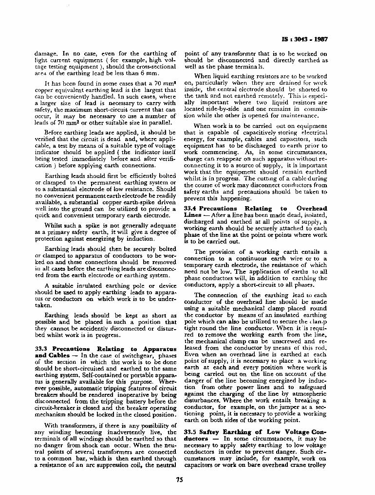
IS : 3043 - 1987
damage. In no case, even for the earthing of light current equipment ( for example, high voltage testing equipment), should the cross-sectional area of the earthing lead be less than 6 mm.
It has been found in some cases that a 70 mm' copper equivalent earthing lead is the largest that can be conveniently handled. In such cases, where a larger size of lead is necessary to carry with safety, the maximum short-circuit current that can occur, it may be necessary to Use a number of leads of 70 mm2 or other suitable size in parallel.
Before earthing leads are applied, it should be verified that the circuit is dead and, where applicable, a test by means of a suitable type of voltage indicator should be applied ( the indicator itself being tested immediately before and after verification ) before applying earth connections.
Earthing leads should first be efficiently bolted or clamped to the permanent earthing system or to a substantial electrode of low resistance. Should no convenient permanent earth electrode be readily available, a substantial copper earth-spike driven well into the ground can be utilized to provide a quick and convenient temporary earth electrode.
Whilst such a spike is not generally adequate as a primary safety earth, it will give a degree of protection against energizing by induction.
Earthing leads should then be securely bolted or clamped to apparatus of conductors to be worked on and these connections should be removed in all cases before the earthing leads are disconnected from the earth electrode or earthing system.
A suitable insulated earthing pole or device should be used to apply earthing leads to apparatus or conductors on which work is to be undertaken.
Earthing leads should be kept as short as possible and be placed in such a position that they cannot be accidently disconnected or disturbed whilst work is in progress.
33.3 Precautions Relating to Apparatus and Gables — In the case of switchgear, phases of the section in which the work is to be done Should be short-circuited and earthed to the same earthing system. Self-contained or portable apparatus is generally available for this purpose. Wherever possible, automatic tripping featnres of circuit breakers should be rendered inoperative by being disconnected from the tripping battery before the circuit-breaker is closed and the breaker operating mechanism should be locked in the closed position.
With transformers, if there is any possibility of any winding becoming inadvertently live, the terminals of all windings should be earthed so that no danger from shock can occur. When the neutral points of several transformers are connected to a common bar, which is then earthed through a resistance of an arc suppression coil, the neutral
point of any transformer that is to be worked on should be disconnected and directly earthed as well as the phase terminals.
When liquid earthing resistors are to be worked on, particularly when they are drained for work inside, the central electrode should be shorted to the tank and not earthed remotely. This is especially important where two liquid resistors are located side-by-side and one remains in commission while the other is opened for maintenance.
When work is to be carried out on equipment that is capable of capacitively storing electrical energy, for example, cables and capacitors, such equipment has to be discharged to earth prior to work commencing. As, in some circumstances, charge can reappear on such apparatus without reconnecting it to a source of supply, it is important work that the equipment should remain earthed whilst is in progress. The cutting of a cable during the course of work may disconnect conductors from safety earths and precautions should be taken to prevent this happening.
33.4 Precautions Relating to Overhead Lines — After a line has been made dead, isolated, discharged and earthed at all points of supply, a working earth should be securely attached to each phase of the line at the point or points where work is to be carried out.
The provision of a working earth entails a connection to a continuous earth wire or to a temporary earth electrode, the resistance of which need not be low. The application of earths to all phase conductors will, in addition to earthing the conductors, apply a short-circuit to all phases.
The connection of the earthing lead to each conductor of the overhead line should be made using a suitable mechanical clamp placed round the conductor by means of an insulated earthing pole which can also be utilized to secure the clamp tight round the line conductor. When it is required to remove the working earth from the line, the mechanical clamp can be unscrewed and released from the conductor by means of this rod. Even when an overhead line is earthed at each point of supply, it is necessary to place a working earth at each and every position where work is being carried out on the line on account of the danger of the line becoming energized by induction from other power lines and to safeguard against the charging of the line by atmospheric disturbances. Where the work entails breaking a conductor, for example, on the jumper at a sectioning point, it is necessary to provide a working earth on both sides of the working point.
33.5 Saftey Earthing of Low Voltage Conductors — In some circumstances, it may be necessary to apply safety earthing to low voltage conductors in order to prevent danger. Such circumstances may include, for example, work on capacitors or work on bare overhead crane trolley
75

IS* 3043-190
wires. Where the earthing- of low voltage conductors is adopted, then the general principles set out in 33.2, 33.3 and 33.4 should be applied and due consideration should be taken of fault current levels ( which can be as nigh or higher than on high voltage systems ), when the size of earth conductor is chosen. 34. MAINTENANCE
TRODES OF EARTH ELEC-
34.1 It is recommended that periodical check tests of all earth electrodes should be carried out. Records should be maintained of such checks. 34.2 Where earth-leakage circuit-breakers are employed, a check shall be kept on the associated earth-electrode by periodically operating the testing device which is embodied in the earthed-leakage circuit-breaker. 34.3 The neighbouring soil to the earth electrode shall be kept moist, where necessary, by periodically pouring water through a pipe where fitted alongwith it or by pouring water in the immediate vicinity of the earth electrode. 34.4 Substations and Generating Station*
34.4.1 Records'shall be kept of the initial resistance of substation and generating station earth electrodes and of subsequent tests carried out.
34.4.2 Normally annual measurement of earth resistance of substation shall be carried out but local circumstances in the light of experience may
justify increase or decrease in this interval but it should not be less than once in two years.
34.4.3 Periodical visual inspection of all earth electrode connection, wherever available, shall be carried out to ensure their rigidity and other signs of deterioration.
34.4.4 In rural substations, particularly those connected to overhead high-voltage and low-voltage lines, greater reliance should be placed on the electrode system, and therefore facilities for testing the resistance of the electrode to general mass of earth, annually or as required by experience, should be provided.
34.4.5 Where installations are earthed to a metal sheath of the supply cable, it shall be verified periodically that the earth-fault loop is in a satisfactory state.
34.4.6 Where an installation is earthed to a cable sheath which is not continuous to the substation neutral ( that is, there is an intervening section of overhead line without earth wire ), a supplementary eleetrode system may be necessary. The adequacy of the electrode system shall be checked initially by an earth-fault loop test.
34.4.7 The neighbouring soil to the earth electrode shall be kept moist, where necessary by periodically pouring water through a pipe where fitted along with it or by pouring water in the immediate vicinity of the earth electrode.
SECTION 10 MEASUREMENTS AND CALCULATIONS
35) CALCULATION OF EARTH FAULT CURRENTS 35.0 General — The magnitude of the current that will flow in the event of a line-to-earth fault on an earthed system is determined by the impedance from the source to the fault plus the impedance of the earth return path, including the impedances of earthing transformers, resistors and reactors (see IS : 5728-1970*). For interconnected systems, the calculation of the current may be complicated.
35.1 Resistance Earthing 35.1.1 When a single line-to-earth fault occurs
on a resistance grounded system, a voltage appears across the resistor nearly equal to the normal line-to-neutral voltage of the system.
35.1.2 In low-resistance grounded systems, the resistor current is approximately equal to die current in the fault, Thus the current is practically equal to the line-to-neutral voltage divided by the resistance in ohms. This simple method is only
♦Guide for ihort-circuitealculatioM.
suitable when the earth fault current is small compared to 3-phase fault current.
35.2 In a resistance-earthed system with a single line-to-earth fault, the earth fault current may be computed from:
'' - Xi X X% + X, + 3 (Xn + Xm) where
/ , — earth fault current in A, Xi ■= system + ve sequence reactance in
O/phase including the subtransient reactance of the rotating machines,
X% — — ve sequence reactance as for Xx, Xo ™ zero sequence reactance as for Zj, Xn ■■ reactance of neutral grounding
reactor, Xar ■» reactance of ground return circuits,
and E =» line-to-earth voltage in V.
In most industrial and commercial systems without inplant generator Xt — X\.
T6
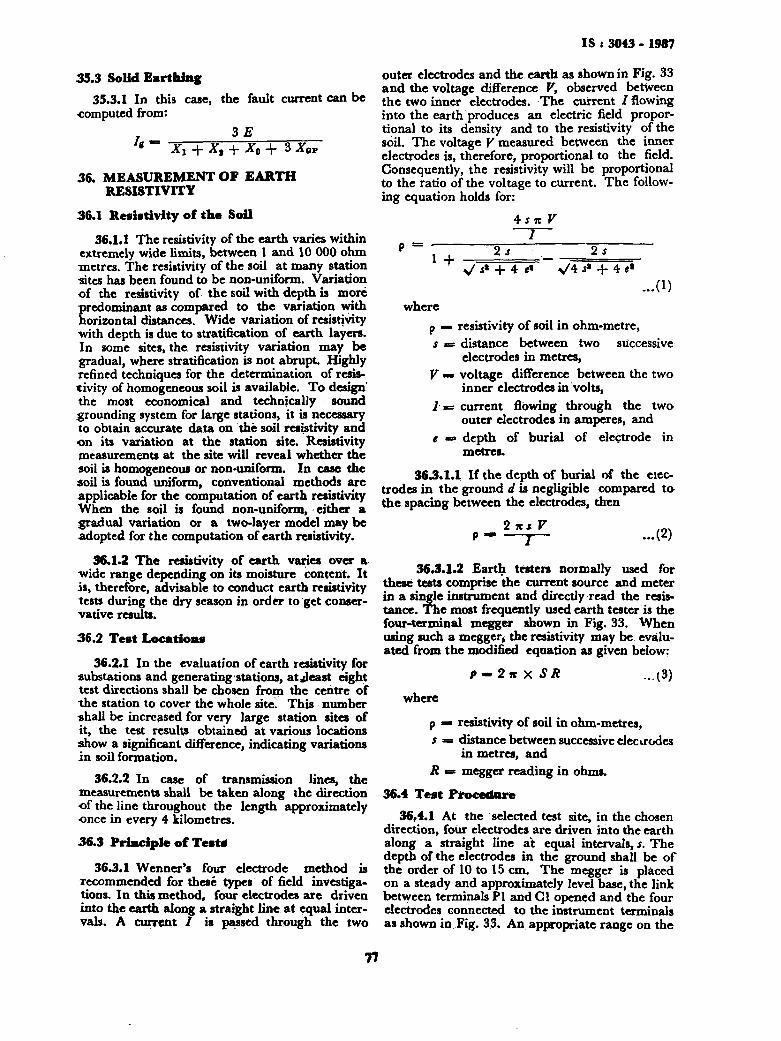
IS : 3043 - 1987
35.3 Solid Earthing 35.3.1 In this case, the fault current can be
computed from:
J* Xt + Xt + X0 + 3 Xar
36. MEASUREMENT OF EARTH RESISTIVITY
36.1 Resistivity of the Soil
36.1.1 The resistivity of the earth varies within extremely wide limits, between 1 and 10 000 ohm metres. The resistivity of the soil at many station -sites has been found to be non-uniform. Variation of the resistivity of the soil with depth is more
Sredominant as compared to the variation with orizontal distances. Wide variation of resistivity
with depth is due to stratification of earth layers. In some sites, the resistivity variation may be gradual, where stratification is not abrupt. Highly refined techniques for the determination of resistivity of homogeneous soil is available. To design' the most economical and technically sound grounding system for large stations, it is necessary to obtain accurate data on the soil resistivity and on its variation at the station site. Resistivity measurements at the site will reveal whether the soil is homogeneous or non-uniform. In case the soil is found uniform, conventional methods are applicable for the computation of earth resistivity When the soil is found non-uniform, either a gradual variation or a two-layer model may be adopted for the computation of earth resistivity.
36.1.2 The resistivity of earth varies over a -wide range depending on its moisture content. It is, therefore, advisable to conduct earth resistivity tests during the dry season in order to get conservative results.
36.2 Test Locations
36.2.1 In the evaluation of earth resistivity for substations and generating stations, at Jeast eight test directions shall be chosen from the centre of the station to cover the whole site. This number shall be increased for very large station sites of it, the test results obtained at various locations show a significant difference, indicating variations in soil formation.
36.2.2 In case of transmission lines, the measurements shall be taken along the direction of the line throughout the length approximately once in every 4 kilometres.
36.3 Principle of Tests
36.3.1 Wenner's four electrode method is recommended for these types of field investigations. In this method, four electrodes are driven into the earth along a straight line at equal intervals. A current / is passed through the two
outer electrodes and the earth as shown in Fig. 33 and the voltage difference V, observed betjveen the two inner electrodes. The current I flowing into the earth produces an electric field proportional to its density and to the resistivity of the soil. The voltage V measured between the inner electrodes is, therefore, proportional to the field. Consequently, the resistivity will be proportional to the ratio of the voltage to current. The following equation holds for:
4sn V I
>/** + *«* V* J* + 4 «* ...(1)
where p — resistivity of soil in ohm-metre, s = distance between two successive
electrodes in metres, V wm voltage difference between the two
inner electrodes in volts, I = current flowing through the two
outer electrodes in amperes, and e «=• depth of burial of electrode in
metres.
36.3.1.1 If the depth of burial of the electrodes in the ground d is negligible compared to the spacing between the electrodes, then
36.3.1.2 Earth testers normally used for these tests comprise the current source and meter in a single instrument and directly read the resistance. The most frequently used earth tester is the four-terminal megger shown in Fig. 33. When using such a megger, the resistivity may be evaluated from the modified equation as given below:
P-2n X SR ...(3)
where
p B resistivity of soil in ohm-metres, s = distance between successive electrodes
in metres, and R = megger reading in ohms.
36.4 Test Procedure 36,4.1 At the selected test site, in the chosen
direction, four electrodes are driven into the earth along a straight line at equal intervals, s. The depth of the electrodes in the ground shall be of the order of 10 to 15 cm. The megger is placed on a steady and approximately level base, the link between terminals PI and Gl opened and the four electrodes connected to the instrument terminals as shown in Fig. 33. An appropriate range on the
77
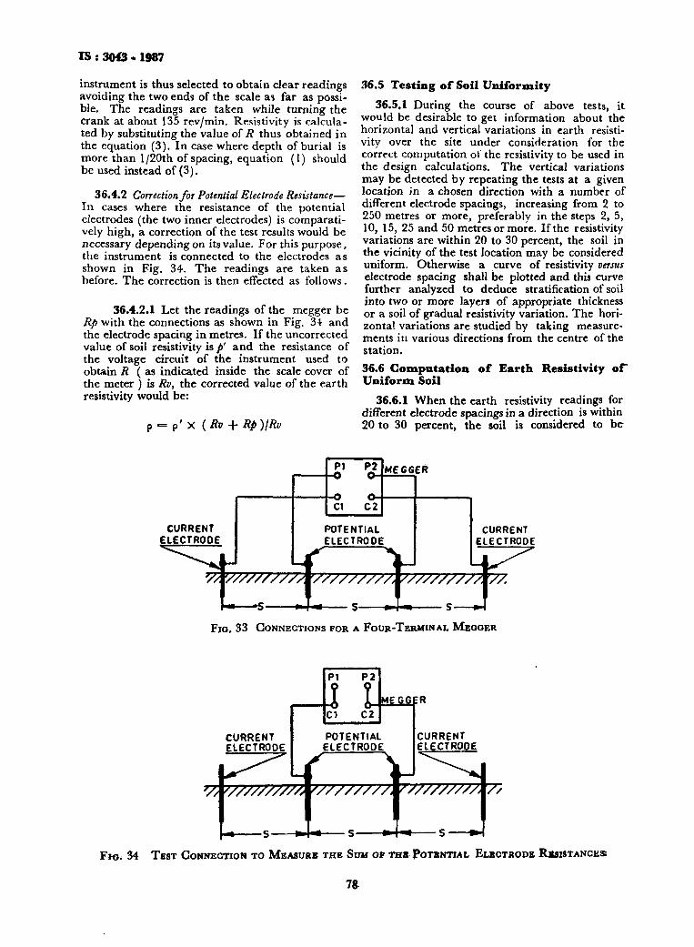
IS : 3043 - 1987
instrument is thus selected to obtain clear readings avoiding the two ends of the scale as far as possible. The readings are taken while turning the crank at about 135 rev/min. Resistivity is calculated by substituting the value of R thus obtained in the equation (3). In case where depth of burial is more than l/20th of spacing, equation (1) should be used instead of (3).
36.4.2 Correction for Potential Electrode Resistance— In cases where the resistance of the potential electrodes (the two inner electrodes) is comparatively high, a correction of the test results would be necessary depending on its value. For this purpose, the instrument is connected to the electrodes as shown in Fig. 34. The readings are taken as before. The correction is then effected as follows.
36.4.2.1 Let the readings of the megger be Rp with the connections as shown in Fig. 34 and the electrode spacing in metres. If the uncorrected value of soil resistivity is p' and the resistance of the voltage circuit of the instrument used to obtain R ( as indicated inside the scale cover of the meter ) is Rv, the corrected value of the earth resistivity would be:
p = p ' x (Rv + Rp)IRv
36.5 Testing of Soil Uniformity 36.5.1 During the course of above tests, it
would be desirable to get information about the horizontal and vertical variations in earth resistivity over the site under consideration for the correct computation of the resistivity to be used in the design calculations. The vertical variations may be detected by repeating the tests at a given location in a chosen direction with a number of different electrode spacings, increasing from 2 to 250 metres or more, preferably in the steps 2, 5, 10, 15, 25 and 50 metres or more. If the resistivity variations are within 20 to 30 percent, the soil in the vicinity of the test location may be considered uniform. Otherwise a curve of resistivity versus electrode spacing shall be plotted and this curve further analyzed to deduce stratification of soil into two or more layers of appropriate thickness or a soil of gradual resistivity variation. The horizontal variations are studied by taking measurements in various directions from the centre of the station. 36.6 Compatation of Earth Resistivity o f Uniform Soil
36.6.1 When the earth resistivity readings for different electrode spacings in a direction is within 20 to 30 percent, the soil is considered to be
MEGGER
CURRENT ELECTRODE
W////////7&7.
Fio. 33 CONNECTIONS FOR A FOUR-TERMINAL MEGGER
FHJ. 34 TEST CONNECTION TO MEASURE THE SUM OP THB POTENTIAL ELECTRODE RESISTANCES
78
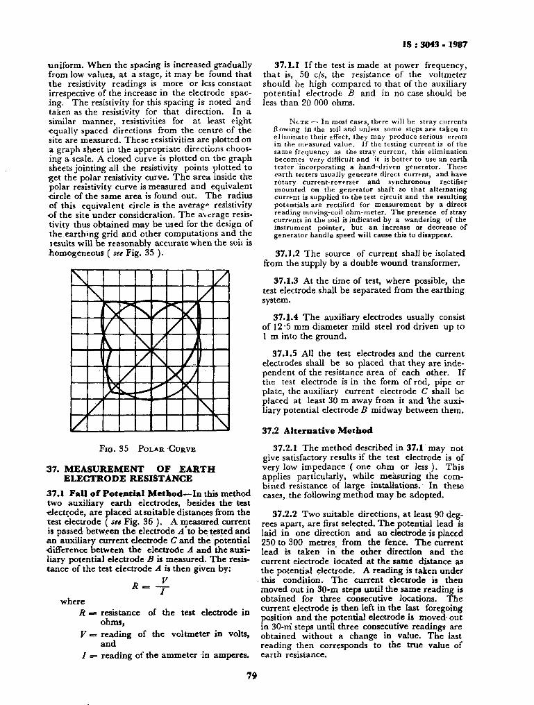
IS : 3043 - 1987
■uniform. When the spacing is increased gradually from low values, at a stage, it may be found that the resistivity readings is more or less constant irrespective of the increase in the electrode spacing. The resistivity for this spacing is noted and taken as the resistivity for that direction. In a similar manner, resistivities for at least eight equally spaced directions from the centre of the site are measured. These resistivities are plotted on a graph sheet in the appropriate directions choosing a scale. A closed curve is plotted on the graph sheets jointing all the resistivity points plotted to get the polar resistivity cixrve. The area inside the polar resistivity curve is measured and equivalent circle of the same area is found out. The radius of this equivalent circle is the average resistivity of the site under consideration. The average resistivity thus obtained may be used for the design of the earthmg grid and other computations and the results will be reasonably accurate when the soil is homogeneous ( see Fig. 35 ).
Fio.35 POLAR CURVE
37. MEASUREMENT OF EARTH ELECTRODE RESISTANCE
37.1 Fall of Potential Method—In this method two auxiliary earth electrodes, besides the test ■electrode, are placed at suitable distances from the test electrode ( see Fig. 36 ). A measured current is passed between the electrode A to be tested and ■an auxiliary current electrode C and the potential difference between the electrode A and the auxiliary potential electrode £ is measured. The resistance of the test electrode A is then given by:
' - - £ where
R -= resistance of the test electrode in ohms,
V = reading of the voltmeter in volts, and
/ = reading of the ammeter in amperes.
79
37.1.1 If the test is made at power frequency, that is, 50 c/s, the resistance of the voltmeter should be high compared to that of the auxiliary potential electrode B and in no case should be less than 20 000 ohms.
N O T E — In most cases, there will be stray currents flowing in the soil and unless some steps are taken to el iminate their effect, they may produce serious errors in the measured value. If the testing current is of the same frequency as the stray current, this elimination becomes very difficult and it is better to use an earth tester incorporating a hand-driven generator. These earth tetters usually generate direct current, and have rotary current-reverser and synchronous rectifier mounted on the generator shaft so that alternating current is supplied to the test circuit and the resulting potentials are rectified for measurement by a direct reading moving-coil ohm-meter. The presence of stray currents in the soil is indicated by a wandering of the instrument pointer, but an increase or decrease of generator handle speed will cause this to disappear.
37.1.2 The source of current shall be isolated from the supply by a double wound transformer.
37.1.3 At the time of test, where possible, the test electrode shall be separated from the earthing system.
37.1.4 The auxiliary electrodes usually consist of 12 '5 mm diameter mild steel rod driven up to 1 m into the ground.
37.1.5 All the test electrodes and the current electrodes shall be so placed that they are independent of the resistance area of each other. If the test electrode is in the form of rod, pipe or plate, the auxiliary current electrode C shall be placed at least 30 m away from it and 'the auxiliary potential electrode B midway between them.
37.2 Alternative Method
37.2.1 The method described in 37.1 may not give satisfactory results if the test electrode is of very low impedance ( one ohm or less ). This applies particularly, while measuring the combined resistance of large installations. In these cases, the following method may be adopted.
37.2.2 Two suitable directions, at least 90 degrees apart, are first selected. The potential lead is laid in one direction and an electrode is placed 250 to 300 metres, from the fence. The current lead is taken in the other direction and the current electrode located at the same distance as the potential electrode. A reading is taken under this condition. The current electrode is then moved out in 30-m steps until the same reading is obtained for three consecutive locations. The current electrode is then left in the last foregoing position and the potential electrode is moved- out in 30-m steps until three consecutive readings are obtained without a change in value. The last reading then corresponds to the true value of earth resistance.
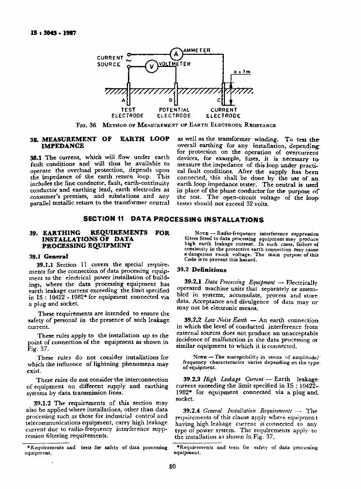
IS t 3043 - 1987
AMMETER CURRENT SOURCE
TEST ELECTRODE
POTENTIAL ELECTROOE
CURRENT ELECTRODE
FIG. 36 METHOD OF MEASUREMENT OF EARTH ELECTRODE RESISTANCE
38. MEASUREMENT OF IMPEDANCE
EARTH LOOP
38.1 The current, which will flow under earth fault conditions and will thus be available to operate the overload protection, depends upon the impedance of the earth return loop. This includes the line conductor, fault, earth-continuity conductor and earthing lead, earth electrodes at consumer's premises, and substations and any parallel metallic return to the transformer neutral
as well as the transformer winding. To test the-overall earthing for any installation, depending: for protection on the operation of overcurrent devices, for example, fuses, it is necessary to-measure the impedance of this loop under practical fault conditions. After the supply has been connected, this shall be done by the use of an earth loop impedance tester. The neutral is used in place of the phase conductor for the purpose of the test. The open-circuit voltage of the loop-tester should not exceed 32 volts.
SECTION 11 DATA PROCESSING INSTALLATIONS
39. EARTHING REQUIREMENTS FOR INSTALLATIONS OF DATA PROCESSING EQUIPMENT
39.1 General 39.1.1 Section l i covers the special require
ments for the connection of data processing equipment to the electrical power installation of buildings, where the data processing equipment has earth leakage current exceeding the limit specified in IS : 10422 - 1982* for equipment connected via a plug and socket.
These requirements are intended to ensure the safety of personal in the presence of such leakage current.
These rules apply to the installation up to the point of connection of the equipment as shown in Fig. 37.
These rules do not consider installations for which the influence of lightning phenomena may exist.
These rules do not consider the interconnection of equipment on different supply and earthing systems by data transmission lines.
39.1.2 The requirements of this section may also be applied where installations, other than data processing such as those for industrial control and telecommunications equipment, carry high leakage current due to radio-frequency interference suppression filtering requirements.
NOTE — Radio-frequency interference suppression filters fitted to data processing equipment may produce high earth leakage current. In such cases, failure of continuity in the protective earth connection may cause a dangerous touch voltage. The main purpose of this Code is to prevent this hazard.
39.2 Definitions
39.2.1 Data Processing Equipment — Electrically operated machine units that separately or assembled in systems, accumulate, process and store data. Acceptance and divulgence of data may or may not be electronic means.
39.2.2 Low Noise Earth — An earth connection-. in which the level of conducted interference from external sources does not produce an unacceptable incidence of malfunction in the data processing or similar equipment to which it is connected.
N O T E — T h e susceptibility in terms of amplitude/' frequency characteristics varies depending on the type-of equipment.
39.2.3 High Leakage Current — Earth leakage-current exceeding the limit specified in IS : 10422-1982* for equipment connected via a plug and socket.
39.2.4 General Installation Requirements — The requirements of this clause apply where equipmen t having high leakage current is connected to any type of power system. The requirements apply to the installation as shown in Fig. 37.
•Requirements and tests for safety of data processing equipment.
•Requirements and tests for safety of data processing equipment.
80
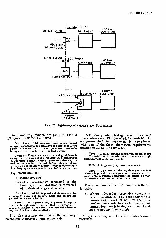
IS i 3043-1387
I
I N S T A L L A T I O N '
EQUIPMENT
EQUIPMENT LOOPED
EQUIPMENT
Cp)— INDUSTRIAL!
PLUG+SOCKETI I I I
INSTALLATION | EQUIPMENT LOOPED
EQUIPMENT
LOOPED INSTALLATION i E Q U I P M | N T EQUIPMENT
WIRING , TERMINALS
FlG. 37 EftUIPMEJW-lNSTALLATION BOUNDARIES
Additional requirements are given for I T and T T systems in 39.2.4.4 and 39.3.
Nora 1 — On TNC systems, where the neutral and protective conductors are contained in a single conductor (PEN conductor ) up to the equipment terminals, leakage current may be treated as load current.
NOTE 2 — Equipment normally having high earth leakage current may not be compatible with installations incorporating residual current protective devices, as well as the standing residual current due to leakage current. The possibility of nuisance tripping due to capacitor charging currents at switch-on shall be considered.
Equipment shall be:
a) stationary, and b) either permanently connected to the
building wiring installation or connected via industrial plugs and sockets.
NOTF. 1 — Industrial plugs and sockets are examples of suitable plugs and sockets. Plugs and sockets .for general use are not suitable.
NOTE 2 — It is particularly important for equipment with high leakage currpnt that earth continuity should be checked at the time it is installed and-after any modification to the installation.
I t is also recommended tha t ear th continuity be checked thereafter at regular intervals.
Additionally, where leakage current measured in accordance with I S : 10422-1982* exceeds 10 mA, equipment shall be connected in accordance with one of the three al ternative requirements detailed in 39 .2 .4 .1 to 39.2.4.3.
NOTE — Leakage current measurements prescribed by IS : 10422-1982* include likely undetected fault conditions within the equipment.
39.2.4.1 High integrity earth connections
NOTE — The aim of the requirements detailed below is to provide high integrity earth connections by using robust or duplicate conductors in association with permanent connections or robust connectors.
Protective conductors shall comply with the following:
a) Where independent protective conductors are, there shall be one conductor with a cross-sectional area of not less than 1 <f> mm* or two conductors with independent terminations, each having a cross-sectional area of not less t han 4 m m ' ;
•Requirements and equipment.
tests for safety of data processing
81
IS < 3043 - 1987
b) When incorporated in a multicore cable together with the supply conductors, the sum total cross-sectional area of all the conductors shall be not less than 1 <f> mm* and the protective conductors shall comply with Section 2;
c) Where the protective conductor is installed in, and connected in parallel with a metal conduit having electrical continuity according to relevant Indian Standard specification on conduits for electrical purposes, a conductor of not less than 2-5 mm* shall be used; and
d) Rigid and flexible metallic conduits, metallic ducting and metallic screens, and armouring which meet the requirements of Section 2.
Each conductor specified in (a), (b), (c) and (d) shall meet the requirements of Section 2.
39.2.4.2 Earth integrity monitoring — A protective device shall be provided which will disconnect the equipment, in the event of a discontinuity occurring in the earth conductor, within the voltage/time limits prescribed by relevant standards.
The protective conductors shall comply with Section 2.
NOTE — The aim of the requirements detailed above is to monitor the continuity of the protective earth connection and provided means of automatic supply disconnection in case of failure.
3^.2.4.3 Use of double wound transformer — Equipment shall be connected to the supply via a double wound transformer of other units in which the input and output circuits are separated, such as motor-alternator sets ( see 40 ) .
The secondary circuit should preferably be connected as a T N system but an I T system may be used where required for the specific application.
NOTE — The aim of the requirements above is to localize the path of the leakage current, and minimize the possibility of a break in continuity in this path.
39.2.4.4 Additional requirements for TT system — The requirements below ensure that the leakage in normal operation of^all equipment protected by one and the same protective device is less than half of that required to operate earth fault protective devices for the installation circuit.
a) The total leakage current 1^ ( in amperes ) , the resistance of the earth electrode RA ( in o h m s ) and the nominal operating residual current of the protective device 7An ( i n amperes) shall be related as follows:
T / A » «r Uj-1 2 ^ 2 RA
b) If the requirements of (a) cannot be met, the requirements of 39.2.4.3 shall apply.
39.3 Addi t i ona l R e q u i r e m e n t s for IT S y s t e m s
39.3.1 It is preferred that equipment with high leakage current is not connected directly to II' systems because ol the difficulty of satisfying touch voltage requirements on a first fault.
Where possible, the equipment is supplied by a T N system derived from the mains supply by means of a double wound transformer.
Where it is possible, the equipment may be connected directly to the equipment may be connected directly to the IT system. This may be facilitated ^by connecting all protective earth connections for equipment using the I T system directly to the power system earth electrode.
39.3.2 Before making direct connection to an I T system, installers shall ensure that equipment is suitable for connection to IT systems according to the declaration of the manufacutrer.
39.4 Safety R e q u i r e m e n t for L o w N o i s e E a r t h i n g Connec t ions
NOTE — It may be found that the electrical noise levels on the protective earthing system of building installations cause an unacceptable incidence of malfunction on a data processing equipment connected to it.
39.4.1 Whatever measures are taken to provide a low-noise earthing connection, it is required that exposed conductive parts of data processing shall be connected to the main earthing terminal.
NOTE — The use of separate earth electrodes for simultaneously accessible exposed conductive parts is not permitted.
This requirement shall also apply to metallic enclosures of Class II and Class III equipment, and to FELV circuits when these are earthed for functional reasons.
Earth conductors, which serve functional purposes only, need not comply with Section 2.
39.4.2 Other Special Methods — In extreme cases, if the safety requirements of 39.4.1 are fulfilled but electrical noise on the main earthing terminal of the installation cannot be reduced to an acceptable level, the installation has to be treated as a special case.
The earthing arrangement has to provide the same level of protection as is generally provided by these requirements and particular attention should be given to ensure that the arrangement:
a) provides adequate protection against over-current;
82
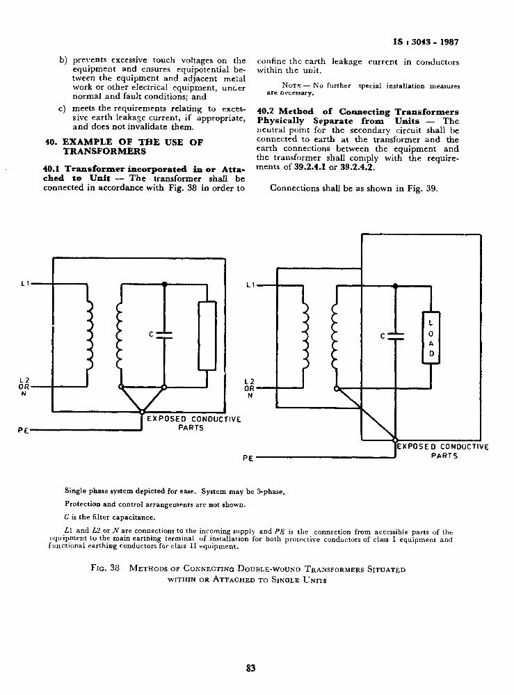
IS i 3043 - 1987
b) prevents excessive touch voltages on the equipment and ensures equipotential between the equipment and adjacent metal work or other electrical equipment, unaer normal and fault conditions; and
c) meets the requirements relating to excessive earth leakage current, if appropriate, and does not invalidate them.
40. EXAMPLE OF THE USE OF TRANSFORMERS
40.1 Transformer incorporated in or Attached to Unit — The transformer shall be connected in accordance with Fig. 38 in order to
confine the earth leakage current in conductors within the unit.
N O T E — No further special installation measures are necessary,
40.2 Method of Connecting Transformers Physically Separate from Units — The neutral point for the secondary circuit shall be connected to earth at the transformer and the earth connections between the equipment and the transformer shall comply with the requirements of 39.2.4.1 or 39.2.4.2.
Connections shall be as shown in Fig. 39.
PC EXPOSED CONDUCTIVE
PARTS
PE EXPOSED CONDUCTIVE
PARTS
Single phase system depicted for ease. System may be 3-phase.
Protection and control arrangements are not shown.
C is the filter capacitance.
L\ and Ul or N are connections to the incoming supply and PE is the connection from accessible parts of the equipment to the main earthing terminal of installation for both protective conductors of class I equipment and functional earthing conductors for class I I equipment.
FIG. 38 METHODS OF GONNEGTINQ DOUBLE-WOUND TRANSFORMERS SITUATED WITHIN OR ATTACHED TO SINGLE UNITS
S3
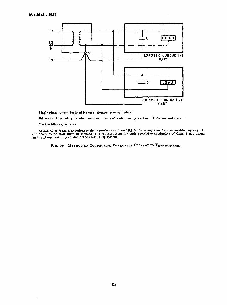
IS i 3043 - 1987
11
12 OR-N
PE- 7K
T l C | L 0 ADJ
EXPOSED CONDUCTIVE PART
T ZJZC | LOAD |
EXPOSED CONDUCTIVE PART
Single-phase system depicted for ease. System may be 3-phase.
Primary and secondary circuits must have means of control and protection. These are not shown.
C is the filter capacitance.
L\ and VI or .Yare connections to the incoming supply and PE is the connection frqm accessible parts of the equipment to the main earthing terminal of the installation for both protective conductors of Class I equipment and functional earthing conductors of Class II equipment.
Fio. 39 METHOD OF CONNECTING PHYSICALLY SEPARATED TRANSFORMERS
84
Bureau of Indian Standards
BIS is a statutory institution established under the Bureau of Indian Standards Act, 1986 to promote harmonious development of the activities of standardization, marking and quality certification of goods and attending to connected matters in the country.
Copyright
BIS has the copyright of all its publications. No part of these publications may be reproduced in any form without the prior permission in writing of BIS. This does not preclude the free use, in the course of implementing the standard, of necessary details, such as symbols and sizes, type or grade designations. Enquiries relating to copyright be addressed to the Director (Publication), BIS.
Review of Indian Standards
Amendments are issued to standards as the need arises on the basis of comments. Standards are also reviewed periodically; a standard along with amendments is reaffirmed when such review indicates that no changes are needed; if the review indicates that changes are needed, it is taken up for revision. Users of Indian Standards should ascertain that they are in possession of the latest amendments or edition by referring to the latest issue of *BIS Handbook' and 'Standards Monthly Additions'.
Amendments Issued Since Publication
Amend No. Date of Issue Text Affected
BUREAU OF INDIAN STANDARDS Headquarters: Manak Bhavan, 9 Bahadur Shah Zafar Marg, New Delhi 110002 Telephones: 323 01 31,323 33 75,323 94 02
Regional Offices:
Central : Manak Bhavan, 9 Bahadur Shah Zafar Marg NEW DELHI 110002
Eastern : 1/14 C.I.T. Scheme VIIM, V.I.P. Road, Maniktola CALCUTTA 700054
Northern : SCO 335-336, Sector 34-A, CHANDIGARH 160022
Southern : C.I.T. Campus, IV Cross Road, CHENNAI 600113
Western : Manakalaya, E9 MIDC, Marol, Andheri (East) MUMBAI400093
Branches : AHMADABAD. BANGALORE. BHCPAL. BHUBANESHWAR. COIMBATORE. FARIDABAD. GHAZIABAD. GUWAHATI. HYDERABAD. JAIPUR. KANPUR. LUCKNOW. NAGPUR. PATNA. PUNE. THIRUVANANTHAPURAM.
Printed at Simco Printing Pros, Delhi, India
Telegrams: Manaksanstha (Common to all offices)
Telephone
323 76 17,323 38 41
f337 84 99,337 85 61 1337 86 26,337 9120
f 60 38 43 160 20 25
f235 0216,235 04 42 123515 19,235 23 15
f 832 92 95, 832 78 58 183278 91,832 78 92