Embed Size (px)
Citation preview

50144829 A August 10, 2015
Thermo Scientific
STERI-CYCLE i160/
STERI-CYCLE i250CO2 Incubator
User Manual

©2015 Thermo Fisher Scientific Inc. All rights reserved.
TrademarksHERACELL VIOS™, Steri-run™, Steri-cycle™, iCan™ and THRIVE™ are registered trademarks of Thermo Scientific.Thermo Scientific is a brand of Thermo Fisher Scientific Inc.All other trademarks mentioned in the operating instructions are the exclusiveproperty of the respective manufacturers.
Thermo Electron LED GmbHRobert-Bosch-Straße 1D - 63505 LangenselboldGermany
Thermo Electron LED GmbH is a subsidiary company of:Thermo Fisher Scientific Inc.81 Wyman StreetWaltham, MA 02454USA
Thermo Fisher Scientific Inc. provides this document to its customers with a product purchase to use in the product operation. This document is copyright protected and any reproduction of the whole or any part of this document is strictly prohibited, except with the written authorization of Thermo Fisher Scientific Inc.
The contents of this document are subject to change without notice. All technical information in this document is for reference purposes only. System configurations and specifications in this document supersede all previous information received by the purchaser.
Thermo Fisher Scientific Inc. makes no representations that this document is complete, accurate or error-free and as-sumes no responsibility and will not be liable for any errors, omissions, damage or loss that might result from any use of this document, even if the information in the document is followed properly.
This document is not part of any sales contract between Thermo Fisher Scientific Inc. and a purchaser. This document shall in no way govern or modify any Terms and Conditions of Sale, which Terms and Conditions of Sale shall govern all conflicting information between the two documents.

T
Table of Contents
Preface .............................................................................................................................................. 1
General notes..........................................................................................................................................1Identification of the device and of the documentation ............................................................................1Identification of the device ................................................................................................................1
Instruction of the operating personnel ....................................................................................................1Applicability of the instructions ..............................................................................................................2Original document for translation .....................................................................................................2
Warranty ................................................................................................................................................2Requirements for warranty .................................................................................................................2
Explanation of safety information and symbols.......................................................................................3Safety information and symbols used in the operating instructions ....................................................3Additional symbols for safety informations: .......................................................................................4Symbols on the device .......................................................................................................................5
Intended purpose of the device ...............................................................................................................5Correct use ........................................................................................................................................5Incorrect use ......................................................................................................................................6
Standards and directives .........................................................................................................................6Safety notes on gases ...............................................................................................................................7Instruction of the personnel: ..............................................................................................................7Safety notes on carbon dioxide (CO2) ...............................................................................................7Safety notes on oxygen (O2) ..............................................................................................................8Safety notes on nitrogen (N2) ............................................................................................................8
Chapter 1 Delivery of the Incubator ................................................................................................... 1-1
Packaging ........................................................................................................................................... 1-1Acceptance inspection......................................................................................................................... 1-1Standard equipment components STERI-CYCLE i160 / i250 ........................................................... 1-2Optional equipment components STERI-CYCLE i160 / i250 ........................................................... 1-2Optional equipment components STERI-CYCLE i160 ..................................................................... 1-2Optional equipment components STERI-CYCLE i250 ..................................................................... 1-3
Chapter 2 Installation of the device ................................................................................................... 2-1
Environmental Conditions ................................................................................................................. 2-1Requirements: ............................................................................................................................... 2-1
Room ventilation................................................................................................................................ 2-2Space requirements ............................................................................................................................. 2-2Transport ........................................................................................................................................... 2-3Stacking.............................................................................................................................................. 2-3Retrofitting/Modifications.................................................................................................................. 2-6
Thermo Scientific STERI-CYCLE i160 / i250 1

Table of Contents
Chapter 3 Description of the device .................................................................................................. 3-1
STERI-CYCLE i160 / i250 Front view .............................................................................................. 3-2STERI-CYCLE i160 / i250 Rear view................................................................................................ 3-4Looped-through gas supply at STERI-CYCLE i160 / STERI-CYCLE i250: ................................. 3-5
Safety devices STERI-CYCLE i160 / i250.......................................................................................... 3-6Workspace atmosphere ....................................................................................................................... 3-6Temperature: ................................................................................................................................. 3-6Relative humidity: ......................................................................................................................... 3-7Water quality recommendations: ................................................................................................... 3-7Prefilter .......................................................................................................................................... 3-7HEPA-filter and air duct ............................................................................................................... 3-8CO2 supply: .................................................................................................................................. 3-9O2 supply: ..................................................................................................................................... 3-9N2 supply: ................................................................................................................................... 3-10
Door switch...................................................................................................................................... 3-10Sensor system ................................................................................................................................... 3-11Supply interface ................................................................................................................................ 3-13Standard interfaces ....................................................................................................................... 3-13Optional interfaces ...................................................................................................................... 3-14Gas connection: ........................................................................................................................... 3-15Label: ........................................................................................................................................... 3-15USB interface: ............................................................................................................................. 3-154-20 mA interface: ....................................................................................................................... 3-15Alarm contact: ............................................................................................................................. 3-16Power supply connection: ............................................................................................................ 3-16
Workspace Components................................................................................................................... 3-17Interior container ......................................................................................................................... 3-17Glass door and optional gas-tight screen ...................................................................................... 3-17Water reservoir ............................................................................................................................ 3-19Heating system ............................................................................................................................ 3-21Rear panel openings ..................................................................................................................... 3-21Shelf system ................................................................................................................................. 3-22
Chapter 4 Start-up ............................................................................................................................... 4-1
Adapting the unit to the ambient atmosphere..................................................................................... 4-1Preparing the workspace ..................................................................................................................... 4-1Installing the “MAX” fill level indicator and the pre-filter .................................................................. 4-2Install the air duct............................................................................................................................... 4-4Installing the HEPA-filter and the water reservoir cover panel ............................................................ 4-5Installing the shelf system ................................................................................................................... 4-7Installation/removal of the support rail .......................................................................................... 4-7Shelf support installation ............................................................................................................... 4-8Levelling the device ........................................................................................................................ 4-8
Mount the split inserts (optional) into the STERI-CYCLE i250 ........................................................ 4-9Gas connection................................................................................................................................. 4-10Installing gas pressure hoses ......................................................................................................... 4-10Gas connection without gas monitoring system ........................................................................... 4-11CO2 connection with gas monitoring system (optional) .............................................................. 4-12Combined CO2 and O2/N2 connection with gas monitoring system (optional) ......................... 4-13
2 STERI-CYCLE i160 / i250 Thermo Scientific

Table of Contents
Power supply connection .................................................................................................................. 4-15Connecting the USB interface: ......................................................................................................... 4-16Connecting the alarm contact: .......................................................................................................... 4-16Connecting the 4-20 mA interface: ................................................................................................... 4-18
Chapter 5 Operation ............................................................................................................................ 5-1
Preparing the device............................................................................................................................ 5-1Starting operation ............................................................................................................................... 5-3
Chapter 6 Handling and control ....................................................................................................... 6-1
Power switch....................................................................................................................................... 6-2Operating panel and operating structure ............................................................................................. 6-3Versions without O2/N2 control ................................................................................................... 6-4Version with combined CO2/O2/N2 control (optional) ............................................................... 6-5Structure of the operating levels ..................................................................................................... 6-5
Factory presettings of the iCan™ Touchscreen controls ....................................................................... 6-7Heat-up phase of the control loop sensors........................................................................................... 6-7Behavior of keys during adjustments ................................................................................................... 6-8Setting the temperature set value......................................................................................................... 6-8Setting the CO2 set value ................................................................................................................... 6-9Setting the O2 set value .................................................................................................................... 6-10auto-start function ............................................................................................................................ 6-12Activating the auto-start routine .................................................................................................. 6-14Interrupting the auto-start routine ............................................................................................... 6-15
Launching steri-run .......................................................................................................................... 6-16User configuration ............................................................................................................................ 6-17Settings / Setup ............................................................................................................................ 6-17Data Logging ............................................................................................................................... 6-27Options ....................................................................................................................................... 6-31Icon description ........................................................................................................................... 6-40Enabling/disabling the keypad lock .............................................................................................. 6-42Software versions ......................................................................................................................... 6-43
Trend display scaling ........................................................................................................................ 6-43Error messages .................................................................................................................................. 6-45Response to an error message event .............................................................................................. 6-45Resetting overtemperature protection ........................................................................................... 6-46
Measures after power outage ............................................................................................................. 6-47Troubleshooting .......................................................................................................................... 6-48
Chapter 7 Shut-down........................................................................................................................... 7-1
Shutting the device down.................................................................................................................... 7-1
Chapter 8 Cleaning and disinfection.................................................................................................. 8-1
Cleaning, ............................................................................................................................................ 8-1Decontamination procedures .............................................................................................................. 8-2Preparing for disinfection or steri-run ................................................................................................. 8-2Wipe/spray disinfection ...................................................................................................................... 8-3Steri-run decontamination routine...................................................................................................... 8-7Activating steri-run ........................................................................................................................ 8-9
Thermo Scientific STERI-CYCLE i160 / i250 3

Table of Contents
cancel steri-run ............................................................................................................................ 8-10Steri-run interruption due to error ............................................................................................... 8-11Completing steri-run ................................................................................................................... 8-12
Chapter 9 Maintenance ....................................................................................................................... 9-1
Inspections and checks........................................................................................................................ 9-1Service Intervals .................................................................................................................................. 9-2Preparing Temperature Calibration .................................................................................................... 9-2Temperature Calibration Procedure ................................................................................................... 9-3Preparing the CO2 calibration............................................................................................................ 9-5CO2 calibration procedure ................................................................................................................. 9-6Replacing the HEPA-filter .................................................................................................................. 9-7Replacing the gas inlet filter................................................................................................................ 9-9Device fusing replacement ................................................................................................................ 9-10Replacing the Door Seal ................................................................................................................... 9-11
Chapter 10 Waste disposal ............................................................................................................... 10-1
Overview of the materials used: ........................................................................................................ 10-1
Chapter 11 Specifications................................................................................................................. 11-1
STERI-CYCLE i160 ........................................................................................................................ 11-2STERI-CYCLE i160 ........................................................................................................................ 11-4STERI-CYCLE i250 ........................................................................................................................ 11-6STERI-CYCLE i250 ........................................................................................................................ 11-8
Chapter 12 Annex: Data communication......................................................................................... 12-1
USB interface .............................................................................................................................. 12-1Installing the USB port driver ...................................................................................................... 12-2
Structure of the command sequences for data communication.......................................................... 12-4Description of protocol ................................................................................................................ 12-4
Overview of general parameters (addresses 0xxx) .............................................................................. 12-5Reading general parameters .......................................................................................................... 12-5
Overview of incubator parameters (addresses 2xxx)........................................................................... 12-5Reading basic parameters ............................................................................................................. 12-6Reading internal function parameters .......................................................................................... 12-7
Error memory structure .................................................................................................................... 12-8Error memory data set structure scheme: ..................................................................................... 12-9Overview of the possible error messages in hex coding ............................................................... 12-10Overview of the possible error messages in bit codingGeneral device status, temperature and CO2 control loop: ..................................................... 12-10
O2 control loop and water level: ................................................................................................ 12-11Data logger structure ...................................................................................................................... 12-11Data logger data set structure scheme: ....................................................................................... 12-13Overview of possible event entries in bit codingOverview of event entries, Part I: ............................................................................................ 12-14
Overview of event entries, Part II: .............................................................................................. 12-15Examples of data logger codes......................................................................................................... 12-15Functions for data logger queries ............................................................................................... 12-16Example of a code for a a data logger query ............................................................................... 12-16
4 STERI-CYCLE i160 / i250 Thermo Scientific

Table of Contents
Program STERI-CYCLE i160 / STERI-CYCLE i250 .................................................................... 12-21Installing the STERI-CYCLE i160 & STERI-CYCLE i250 ...................................................... 12-22Operating the STERI-CYCLE i160 & STERI-CYCLE i250 ..................................................... 12-23
Chapter 13 Device log ....................................................................................................................... 13-1
Chapter 14 Contact Information Thermo Scientific ........................................................................ 14-1
Thermo Scientific STERI-CYCLE i160 / i250 5

Table of Contents
6 STERI-CYCLE i160 / i250 Thermo Scientific

F
Figures
Figure 2-1. Device dimensions ................................................................................................................2-2
Figure 2-2. Lift points .............................................................................................................................2-3
Figure 2-3. Stacking ................................................................................................................................2-4
Figure 2-4. Stacking adapter and base rack with stacking elements ..........................................................2-5
Figure 2-5. Fastening the adapter plate to the lower unit.........................................................................2-5
Figure 3-1. STERI-CYCLE i160 / i250 Front view.................................................................................3-2
Figure 3-2. STERI-CYCLE i160 / i250 Rear view ..................................................................................3-4
Figure 3-3. Looped-through gas supply STERI-CYCLE i160 / STERI-CYCLE i250..............................3-5
Figure 3-4. HEPA-filter and airbox .........................................................................................................3-8
Figure 3-5. Air duct.................................................................................................................................3-9
Figure 3-6. Door switch ........................................................................................................................3-10
Figure 3-7. Temperature, O2, CO2 and humidity sensors ....................................................................3-11
Figure 3-8. Sensors for water level .........................................................................................................3-12
Figure 3-9. Interfaces (right side of control box)....................................................................................3-13
Figure 3-10. Optional interfaces (left side of control box) .....................................................................3-14
Figure 3-11. STERI-CYCLE i160 with glass door.................................................................................3-18
Figure 3-12. STERI-CYCLE i160 with threefold gas-tight screen .........................................................3-19
Figure 3-13. Water reservoir..................................................................................................................3-20
Figure 3-14. Drain valve of water reservoir............................................................................................3-20
Figure 3-15. Rear panel openings ..........................................................................................................3-21
Figure 3-16. Shelf system components ..................................................................................................3-22
Figure 4-1. “MAX” fill level indicator .....................................................................................................4-2
Figure 4-2. „MAX“ fill level indicator and pre-filter ................................................................................4-3
Figure 4-3. Assembling the air duct .........................................................................................................4-4
Figure 4-4. Assembling the HEPA-filter and the airbox...........................................................................4-5
Figure 4-5. Place the airbox onto the Water reservoir cover panel............................................................4-6
Figure 4-6. Installing the airbox ..............................................................................................................4-6
Figure 4-7. Support rail installation/removal ...........................................................................................4-7
Figure 4-8. Shelf support installation.......................................................................................................4-8
Figure 4-9. Installation of split inserts .....................................................................................................4-9
Figure 4-10. Installing gas pressure hoses...............................................................................................4-10
Figure 4-11. Gas connection without gas monitoring system ................................................................4-11
Figure 4-12. CO2 connection with gas monitoring system (optional) ...................................................4-12
Thermo Scientific STERI-CYCLE i160 / i250 1

Figures
Figure 4-13. Combined CO2/O2/N2 connection with gas monitoring system (optional).....................4-13
Figure 4-14. Power supply connection ..................................................................................................4-15
Figure 4-15. Connection example alarm contact ...................................................................................4-17
Figure 4-16. Pin-out of the 4-20 mA interface ......................................................................................4-18
Figure 5-1. Water reservoir......................................................................................................................5-3
Figure 5-2. “MAX” fill level indicator .....................................................................................................5-4
Figure 6-1. Power switch.........................................................................................................................6-2
Figure 6-2. Main screen: Touch-sensitive screen areas .............................................................................6-3
Figure 6-3. iCan™ Touchscreen without O2/N2 gas supply ....................................................................6-4
Figure 6-4. iCan™ Touchscreen with combined gas connection...............................................................6-5
Figure 6-5. Menu structure overview.......................................................................................................6-6
Figure 6-6. Heat-up phase display ...........................................................................................................6-7
Figure 6-7. Temperature display field and temperature selection menu ...................................................6-8
Figure 6-8. Setting the temperature set value...........................................................................................6-9
Figure 6-9. CO2 display and CO2 menu ................................................................................................6-9
Figure 6-10. Setting the CO2 set value..................................................................................................6-10
Figure 6-11. O2 display and O2 menu..................................................................................................6-11
Figure 6-12. Setting the O2 set value ....................................................................................................6-11
Figure 6-13. Activating the auto-start routine........................................................................................6-14
Figure 6-14. auto-start-status display window .......................................................................................6-15
Figure 6-15. Interrupting the auto-start routine ....................................................................................6-16
Figure 6-16. Error message subsequent to aborted auto-start .................................................................6-16
Figure 6-17. User configuration menu ..................................................................................................6-17
Figure 6-18. Settings/Setup menu .........................................................................................................6-18
Figure 6-19. Changing the keypad lock code.........................................................................................6-18
Figure 6-20. Changing the keypad lock code.........................................................................................6-19
Figure 6-21. Date/Time menu ..............................................................................................................6-20
Figure 6-22. Setting the date .................................................................................................................6-20
Figure 6-23. Setting the time.................................................................................................................6-21
Figure 6-24. Adjusting display brightness ..............................................................................................6-22
Figure 6-25. Adjusting key tone volume................................................................................................6-23
Figure 6-26. Interface USB menu..........................................................................................................6-24
Figure 6-27. USB interface baud rate setting .........................................................................................6-24
Figure 6-28. Language setting ...............................................................................................................6-25
Figure 6-29. Choose the desired reminder interval function. .................................................................6-26
Figure 6-30. Setting the reminder interval for steri-run .........................................................................6-27
Figure 6-31. Event logging menu ..........................................................................................................6-28
Figure 6-32. Event display.....................................................................................................................6-28
Figure 6-33. Logging cycle setting .........................................................................................................6-29
Figure 6-34. Displaying the error table..................................................................................................6-31
2 STERI-CYCLE i160 / i250 Thermo Scientific

Figures
Figure 6-35. Options menu.................................................................................................................. 6-32
Figure 6-36. Alarm menu ..................................................................................................................... 6-32
Figure 6-37. Alarm relay setting............................................................................................................ 6-33
Figure 6-38. Low humidity setting ....................................................................................................... 6-34
Figure 6-39. Gas tight screen setting..................................................................................................... 6-35
Figure 6-40. Setting the water level sensor ............................................................................................ 6-36
Figure 6-41. Alarm relay setting............................................................................................................ 6-37
Figure 6-42. Switching the O2 control on and off ................................................................................ 6-38
Figure 6-43. HEPA configuration ........................................................................................................ 6-39
Figure 6-44. Activating / de-activating the HEPA-filter........................................................................ 6-39
Figure 6-45. Icon description ............................................................................................................... 6-40
Figure 6-46. Gas monitoring icons ....................................................................................................... 6-41
Figure 6-47. Enabling/disabling the keypad lock .................................................................................. 6-43
Figure 6-48. Software versions.............................................................................................................. 6-43
Figure 6-49. Invoking the CO2 concentration graph display................................................................ 6-44
Figure 6-50. Invoking the CO2 concentration graph display................................................................ 6-44
Figure 6-51. Event error messages......................................................................................................... 6-46
Figure 6-52. Failure message Overtemperature ..................................................................................... 6-46
Figure 6-53. Failure message Overtemperature ..................................................................................... 6-47
Figure 7-1. Drain valve of water reservoir ............................................................................................... 7-1
Figure 8-1. Drain valve of water reservoir ............................................................................................... 8-2
Figure 8-2. HEPA-filter and airbox ........................................................................................................ 8-5
Figure 8-3. Air duct................................................................................................................................ 8-6
Figure 8-4. Decontamination routine phases .......................................................................................... 8-9
Figure 8-5. steri-run menu - Progress ..................................................................................................... 8-9
Figure 8-6. activate steri-run................................................................................................................. 8-10
Figure 8-7. Interrupting / cancelling steri-run....................................................................................... 8-11
Figure 8-8. To stop steri-run ................................................................................................................ 8-12
Figure 9-1. Preparing Temperature Calibration...................................................................................... 9-3
Figure 9-2. Temperature display field and temperature selection menu .................................................. 9-4
Figure 9-3. Temperature Calibration Procedure ..................................................................................... 9-4
Figure 9-4. Gas-tight screen measurement opening ................................................................................ 9-6
Figure 9-5. CO2 calibration procedure................................................................................................... 9-7
Figure 9-6. Removing the airbox ............................................................................................................ 9-8
Figure 9-7. Installing the HEPA-filter .................................................................................................... 9-9
Figure 9-8. Gas inlet filter installation .................................................................................................. 9-10
Thermo Scientific STERI-CYCLE i160 / i250 3

Figures
4 STERI-CYCLE i160 / i250 Thermo Scientific

P
Preface
General notes
Identification of the device and of the documentation
Identification of the device
Identification dataDevice name: CO2 incubatorType designation: STERI-CYCLE i160
STERI-CYCLE i250
Allocation of product documentation
Documents CD-ROM 50143971
Certifications and quality audit:Certification: CE CertificationTest mark: TÜV GS, cCSAus, EAC
Instruction of the operating personnel
These operating instructions describe the CO2 incubator STERI-CYCLE i160 / STERI-CYCLE i250. The CO2 incubator has been manufactured in keeping with the latest technological developments and is operationally safe. However, the device may present potential hazards, particularly if it is operated by inadequately trained personnel or if it is not used in accordance with the intended purpose. Therefore, the following must be observed to prevent accidents:
• The CO2 incubator must be operated only by trained and authorized personnel.
• For any operation of this device, the operator must prepare clear and concise written instructions in the language of the operating and cleaning personnel based on these operating instructions, applicable safety data sheets, plant hygiene guidelines, and technical regulations, in particular:
• which decontamination measures are to be applied for the device and accessories,
• which protective measures apply when specific agents are used,
• which measures are to be taken in the case of an accident.
• Repairs to the device must be carried out only by trained and authorized expert personnel.
Thermo Scientific STERI-CYCLE i160 / i250 1

PrefaceApplicability of the instructions
Applicability of the instructions
Original document for translation
• The contents of the operating instructions are subject to change without further notice.
• In case of conflicting translations into foreign languages the German-language version of these operating instructions shall be binding.
• Keep these operating instructions close to the device so that safety instructions and important information are always accessible.
Should you encounter problems that are not detailed adequately in these operating instructions, please contact Thermo Scientific immediately for your own safety.
Warranty
Requirements for warranty
Thermo Scientific warrants the operational safety and functions of the CO2 incubator only under the condition that:
• the device is operated and serviced exclusively in accordance with its intended purpose and as described in these operating instructions,
• the device is not modified,
• only original spare parts and accessories that have been approved by Thermo Fisher Scientific are used,
• inspections and maintenance are performed at the specified intervals.
The warranty is valid from the date of delivery of the device to the operator.
2 STERI-CYCLE i160 / i250 Thermo Scientific
Preface
Explanation of safety information and symbols
Explanation of safety information and symbols
Safety information and symbols used in the operating instructions
WARNING Indicates a hazardous situation which, if not avoided, could result in death or serious injuries.
CAUTION Indicates a hazardous situation which, if not avoided, could result in minor or moderate injuries.
CAUTION Indicates a situation which, if not avoided, could result in property damage.
Note Is used for application al hints and useful information.
Thermo Scientific STERI-CYCLE i160 / i250 3

PrefaceExplanation of safety information and symbols
Additional symbols for safety informations:
Wear safety gloves!
Wear safety goggles!
Harmful liquids!
Electric shock!
Hot surfaces!
Fire hazard!
Explosion hazard!
Suffocation hazard!
4 STERI-CYCLE i160 / i250 Thermo Scientific

Preface
Intended purpose of the device
Symbols on the device
Intended purpose of the device
Correct use
This CO 2 incubator is designed for preparing and cultivating cell cultures, but it is not to be used for medical applications or for in-vitro-diagnostics. To that end, a controlled set of physiological ambient conditions is produced in the workspace of the device by exerting precise control of the following parameters:
• Temperature
• CO2 content
• O2/N2 content
• Relative humidity
CE conformity mark: confirms conformity according to EU Guidelines
TÜV-tested safety
Mark of conformity USA/Canada
EAC conformity mark: confirms conformity according to all technical regulations of the Eurasian customs union (Russia, Kazakhstan and Belarus)
Observe operating instructions!
Hot surfaces!
Thermo Scientific STERI-CYCLE i160 / i250 5

PrefaceStandards and directives
Typically, this CO2 incubator has been designed for being installed and operated in the following areas:
• Laboratories for cytobiological and biotechnological experiments of safety levels L1, L2, and L3
• Medical-microbiological laboratories in accordance with DIN EN 12128
• Research labs in clinics and hospitals
This device is intended for professional use only and must only be operated by trained staff.
Incorrect use
Do not use cell or tissue cultures in the device that are not in accordance with the regulations of safety levels L1, L2, and L3. Do not use tissues, substances or liquids that:
• Are easily ignitable or explosive,
• release vapors that form combustible or explosive mixtures when exposed to air,
• release poisons.
Standards and directives
The device complies with the following standards and guidelines:
• Low Voltage Directive 2006/95/EC
• IEC 61010-1:2010+Corr. 2011, Safety requirements for electrical equipment for measurement, control and laboratory use - Part 1: General requirements
• IEC 61010-2-010:2003, Safety requirements for electrical equipment for measurement, control, and laboratory use - Part 2-010: Particular requirements for laboratory equipment for the heating of material
• EMC Directive 2004/108/EC
• IEC 61326-1:2012, Electrical equipment for measurement, control and laboratory use - EMC requirements, Part 1: General requirements
• FCC 47, Part 15, § 15.107, Measurement 2015, EMC regulation FCC
• FCC 47. Part 15, § 15.109, Measurement 2015, EMC regulation FCC
For other countries, the applicable national regulations are binding.
6 STERI-CYCLE i160 / i250 Thermo Scientific

Preface
Safety notes on gases
Safety notes on gases
Instruction of the personnel:
Personnel operating devices with CO2 supply must be instructed about the particularities in the handling of CO2 before starting their work:
• Correct operation of pressurized gas containers and gas supply systems,
• obligation to report damages and shortcomings in CO2 supply lines,
• measures to be taken in case of accidents or failures.
These instructions must be repeated at appropriate intervals and must comprise the particular operating instructions of the gas supplier.
Safety notes on carbon dioxide (CO2)
Since CO2 is rated as a harmful gas, certain safety instructions must be observed when the CO2 incubator is started up and when the device is operated.
Note Installation work:Any work on supply lines and pressurized gas containers, cylinders or containers used for storing CO2- or O2/N2 must only be carried out by expert personnel using the appropriate tools.
Note
It must be ensured that the exposure limits at work place for CO2 and/or O2/N2 are not exceeded.For the Federal Republic of Germany the TRGS 900 should be observed; other countries may have different limit values. The country-specific national exposure limits at work place shall be met.
Suffocation hazard!Large amounts of carbon dioxide (CO2) released into the room atmosphere may cause suffocation.If CO2 is released, initiate safety measures immediately!
• Leave the room immediately and do not allow others to enter the room!
• Inform security service or fire department!
Thermo Scientific STERI-CYCLE i160 / i250 7

PrefaceSafety notes on gases
Safety notes on oxygen (O2)
O2 is a gas that promotes combustion and may explode in combination with grease-containing materials.
Safety notes on nitrogen (N2)
Nitrogen mixes easily with air. High concentrations of nitrogen reduce the oxygen content in the air.
Oxygen explosion!Oxygen (O2) may explode in combination with oils, greases, and lubricants. If highly compressed oxygen comes in contact with grease- or oil-containing substances, the mixture may explode! Control panel and display window protective foil!
• For cleaning these device components, use only oil- and grease-free lubricants.
Keep all connections and components of the oxygen system free from substances that contain oil, grease, or lubricant!
Fire hazard!
Released oxygen (O2) promotes combustion. Do not use open flames in the vicinity of oxygen-operated systems!
• Do not smoke in the vicinity of oxygen systems.
Do not expose the components of an oxygen system to excessive heat.
Suffocation hazard!Large amounts of nitrogen (N2) released into the room atmosphere may cause suffocation. If N2 is released, initiate safety measures immediately!
• Leave the room immediately and do not allow others to enter the room!
• Inform security service or fire department!
8 STERI-CYCLE i160 / i250 Thermo Scientific

1
Delivery of the Incubator
Packaging
The CO2-Incubator STERI-CYCLE i160 / STERI-CYCLE i250 is delivered in a stable packaging box. All packaging materials can be separated and are reusable:
• Packaging carton: Recycled paper
• Foam elements: Styrofoam (CFC-free)
• Packaging film: Polyethylene
• Packaging ribbons: Polypropylene
• Feet: Polypropylene
• Pallet: Untreated wood
Acceptance inspection
After the incubator has been delivered, check the delivery immediately for:
• completeness,
• possible damage.
If components are missing or damage is found on the device or the packaging, esp. damages caused by humidity and water, please contact the linehauler as well as the Technical Support of Thermo Scientific immediately.
Content
• “Packaging“ on page 1-1
• “Acceptance inspection“ on page 1-1
• “Standard equipment components STERI-CYCLE i160 / i250“ on page 1-2
• “Optional equipment components STERI-CYCLE i160 / i250“ on page 1-2
• “Optional equipment components STERI-CYCLE i250“ on page 1-3
Thermo Scientific STERI-CYCLE i160 / i250 1-1

1 Delivery of the IncubatorStandard equipment components STERI-CYCLE i160 / i250
Standard equipment components STERI-CYCLE i160 / i250
Optional equipment components STERI-CYCLE i160 / i250
Optional equipment components STERI-CYCLE i160
Quantity of components supplied Pieces
Water reservoir cover panel 1
Max. water level sensor 1
Rear wall air duct 1
Airduct top 1
Airbox with sealing package 1
Prefilter 1
Shelves 3
Support rails for shelves 4
Shelf support for inserts 6
Plug for access port 1
Power Cord 1
CO2 connecting hose set 1
User Manual 1
Quick-release connector with hose for water draining 1
Components delivered with oxygen supply control option Pieces
O2 sensor head 1
O2 connecting hose set 1
Components delivered with CO2 gas tank monitor option
CO2 gas tank monitor connecting hose set 1
Components delivered with O2/N2 gas tank monitor option
O2 connecting hose set/N2 gas tank monitor 1
Components delivered with filter option
HEPA-filter or VOC filter 1
Optional equipment components 4...20mA interface
Connector 4...20mA 1
Components Pieces
Threefold gas-tight screen 1
1-2 STERI-CYCLE i160 / i250 Thermo Scientific

1 Delivery of the Incubator
Optional equipment components STERI-CYCLE i250
Optional equipment components STERI-CYCLE i250
Components delivered with 250 liter units with split inserts Pieces
Support brackets 3
Split inserts 6
Sixfold gas-tight screen 1
Thermo Scientific STERI-CYCLE i160 / i250 1-3

1 Delivery of the IncubatorOptional equipment components STERI-CYCLE i250
1-4 STERI-CYCLE i160 / i250 Thermo Scientific

2
Installation of the device
Environmental Conditions
The device must only be operated at locations that meet the particular ambient conditions listed below:
Requirements:
• Draft-free and dry location.
• The minimal distance to adjacent surfaces must be observed on all sides, see “Space requirements“ on page 2-2.
• The operating room must be equipped with appropriate room ventilation.
• Solid, level, fire-proof surface.
• Vibration-proof substructure (floor stand, lab table) capable of bearing the weight of the device and of accessories (particularly if several devices are stacked).
• The electrical system of the device has been designed for an operating height of up to 2000 m above sea level.
• To ensure a constant incubation temperature of 37 °C, the ambient temperature must be within a range of +18 °C to +34 °C.
• Relative humidity up to 80% (max.).
• No direct exposure to sunlight.
• Devices that produce excessive heat must not be placed near the location of STERI-CYCLE i160 / STERI-CYCLE i250
Table of Contents
• “Environmental Conditions“ on page 2-1
• “Room ventilation“ on page 2-2
• “Space requirements“ on page 2-2
• “Transport“ on page 2-3
• “Stacking“ on page 2-3
• “Retrofitting/Modifications“ on page 2-6
Thermo Scientific STERI-CYCLE i160 / i250 2-1

2 Installation of the deviceRoom ventilation
Room ventilation
When CO2-/O2-/N2 is supplied, the workspace of the incubator is slightly pressurized. The pressure is released through the pressure compensation opening into the operating room. Pressure compensation and any opening of the glass door/gas-tight screen during the operation of the device will release very small quantities of CO2-/O2-/N2 into the operating room. The room ventilation must be capable of carrying the released gas safely off into the open.In addition, heat dissipating from the device during continuous operation may cause a change in the room climate.
• Therefore, the STERI-CYCLE i160 / STERI-CYCLE i250 must only be installed in rooms with sufficient ventilation.
• Do not install the device in room recesses without ventilation.
• The room ventilation should be a technical ventilation that complies with the national requirements for laboritories or some other suited ventilation system with appropriate capacity.
Space requirements
Figure 2-1. Device dimensions
WARNING EMERGENCY STOP!The mains socket must be accessible at all times for the case of an EMERGENCY STOP. The mains socket must be easily identifiable by the user and freely accessible at all times.
Note Accessibility of the devices: To ensure the accessibility for care and maintenance works, keep larger side and rear distances.
STERI-CYCLE
i250
780
934
970
173
945
90
75 STERI-CYCLE
i160
637
≥173
90
7509
All dimensions in mm.
2-2 STERI-CYCLE i160 / i250 Thermo Scientific

2 Installation of the device
Transport
Transport
For transport, do not lift the device using the doors or components attached to the device (e.g. control box on rear panel) as lift points.
Figure 2-2. Lift points
Stacking
STERI-CYCLE i160 / STERI-CYCLE i250 is suited for stacking up to two devices of the same device type. This is accomplished by placing an optional stacking adapter (1/Figure 2-3) between the two units.
As an option, a mobile base rack (2/Figure 2-3) is available in order for the units to be movable. The rollers of the base rack are fitted with a locking brake.
Note Lift points:
Lift the device only using the lift points.
CAUTION Heavy loads! Lift with care!To avoid injury through physical strain, such as strain traumata and slipped discs, do not attempt to lift the incubator alone!To avoid injury through dropped loads, be sure to wear Personal Protection Equipment, such as safety shoes, when lifting the incubator.To avoid crushing your fingers or hands (particularly in a closing door) or damaging the incubator, do not use any other lift points than those indicated in the illustration above.
Note
when installing the stacking adapter and stacking the units, follow the assembly instructions delivered with the stacking adapter.
Thermo Scientific STERI-CYCLE i160 / i250 2-3

2 Installation of the deviceStacking
Figure 2-3. Stacking
Note Moving stacked devices:Stacked devices provided with a mobile base rack must only be moved inside rooms on even floors without any slopes.
2-4 STERI-CYCLE i160 / i250 Thermo Scientific

2 Installation of the device
Stacking
STERI-CYCLE i160 and STERI-CYCLE i250:
1. Place the lower unit with the device stands (3/Figure 2-4) on the stacking elements (1/Figure 2-4 on top of the mobile base rack (2/Figure 2-4).
Figure 2-4. Stacking adapter and base rack with stacking elements
2. Place bottom of adapter plate (7/Figure 2-5) on the top panel of the lower unit (8/Figure 2-5.
3. On both sides, align the bores in the connecting tab (9/Figure 2-5) of the adapter plate (7/Figure 2-5) with the bores in the rear wall of the lower unit (8/Figure 2-5).
Figure 2-5. Fastening the adapter plate to the lower unit
4. Use the fastening screws supplied to bolt the adapter plate (7/Figure 2-5) to the rear wall of the lower unit (8/Figure 2-5).
5. Fasten adapter plate (7/Figure 2-5) to the opposite corner of the unit using two screws.
6. Place the device to be stacked with the device stands (6/Figure 2-5) onto the stacking elements (1/Figure 2-4) at the top of the adapter plate.
3
2
1
6
7
8
9
Thermo Scientific STERI-CYCLE i160 / i250 2-5

2 Installation of the deviceRetrofitting/Modifications
The devices are secured to one another by their own weight..
Retrofitting/Modifications
The following components can be retrofitted to the standard version:
STERI-CYCLE i160
• threefold gas-tight screen (the gas-tight screen is installed in place of the glass door),
• door hinge replacement on outer door and glass door,
• lockable outer door,
• infrared (IR) CO2 sensor (replaces the standard TCD sensor),
• 4-20 mA data interface.
• gas cylinder monitor
STERI-CYCLE i250
• threefold gas-tight screen (the gas-tight screen is installed in place of the glass door),
• door hinge replacement on outer door and glass door,
• lockable outer door,
• split inserts,
• infrared (IR) CO2 sensor (replaces the standard TCD sensor),
• 4-20 mA data interface.
• gas cylinder monitor
CAUTION Transporting stacked devices!Stacking elements are no connection elements. Stacked devices provided with a mobile base rack must only be moved inside rooms on even floors without any slopes.
Note Fastening on mobile racks:If the devices are installed onto mobile racks, make sure that the rollers are secured with a locking brake during the operation of the incubators and that the rollers are oriented toward the front for increased stability.
Condensate formation during the operation of stacked devices: As a rule when operating stacked devices of type STERI-CYCLE i160 and i250, an adapter plate should be placed between the two devices for thermal separation.If stacked devices are operated at an ambient temperature of more than 28 °C, an overtemperature alarm is triggered on the upper device while the steri-run decontamination routine is run for the lower device. Condensate formation may then occur on the upper device.
Note Modifications: Retrofittings and modifications must only be performed by the Technical Service of Thermo Electron LED GmbH.
2-6 STERI-CYCLE i160 / i250 Thermo Scientific

3
Description of the device
Table of Contents
• “STERI-CYCLE i160 / i250 Front view“ on page 3-2
• “STERI-CYCLE i160 / i250 Rear view“ on page 3-4
• “Safety devices STERI-CYCLE i160 / i250“ on page 3-6
• “Workspace atmosphere“ on page 3-6
• “Door switch“ on page 3-10
• “Sensor system“ on page 3-11
• “Supply interface“ on page 3-13
• “Workspace Components“ on page 3-17
Thermo Scientific STERI-CYCLE i160 / i250 3-1

3 Description of the deviceSTERI-CYCLE i160 / i250 Front view
STERI-CYCLE i160 / i250 Front view
Figure 3-1. STERI-CYCLE i160 / i250 Front view
1
18
432
8
6
5
7
1920
21
16
14a,b
17
15
13
10
9
11
4
9
16
10
9
12
14a
14b
3-2 STERI-CYCLE i160 / i250 Thermo Scientific

3 Description of the device
STERI-CYCLE i160 / i250 Front view
1. Pressure compensation opening /Access port with plug
2. Door switch for glass door
3. Temperature Sensor
4. O2 sensor (optional)
5. Door handle for the glass door or the gas-tight screen
6. Glass door or gas-tight screen (optional)
7. Outer door
8. Magnetic door seal, replaceable
9. Prefilter
10. Water drain
11. Stand, height-adjustable
12. Glass door seal, replaceable
13. Airbox with seal and HEPA-filter
14. a: Bottom insert (standard feature set)b: Bottom insert with cut-out for refilling (optional, only for STERI-CYCLE i160)
15. Support rail
16. Insert with shelf support
17. rH sensor (with TCD sensor only)
18. CO2 sensor
19. Door handle, outer door
20. iCan™ Touchscreen (Control panel)
21. Power switch
Thermo Scientific STERI-CYCLE i160 / i250 3-3

3 Description of the deviceSTERI-CYCLE i160 / i250 Rear view
STERI-CYCLE i160 / i250 Rear view
Figure 3-2. STERI-CYCLE i160 / i250 Rear view
1. Control box with supply interface for combined gas connection (optional) CO2 and O2/N2 without gas monitoring
2. Diagram: CO2 and O2/N2 gas connection without gas monitoring
3. O2 /N2 gas cylinder
4. CO2 gas cylinder
5. Primary CO2 gas supply A with optional gas monitoring
6. Secondary CO2 gas supply B with optional gas monitoring
7. Control box with supply interface for combined gas connection (optional) CO2 and O2 /N2 with gas monitoring (optional)
8. Primary O2-/N2 gas supply A with optional gas monitoring
9. Secondary O2-/N2 gas supply B with optional gas monitoring
10. Diagram: CO2 and O2/N2 gas connection with optional gas monitoring
1
7
8
9
1011
2
3
5
4
6
3-4 STERI-CYCLE i160 / i250 Thermo Scientific

3 Description of the device
STERI-CYCLE i160 / i250 Rear view
11. Distributor connection for looping through the CO2 gas supply for up to three additional devices (independent of device type)
Hidden: Distributor connection for looping through the O2-/N2 gas supply for three additional devices, opposite to the control box
Looped-through gas supply at STERI-CYCLE i160 / STERI-CYCLE i250:
Figure 3-3. Looped-through gas supply STERI-CYCLE i160 / STERI-CYCLE i250
1. Control box with supply interface for combined gas connection (optional) CO2 and O2/N2 with gas monitoring (optional)
2. Distributor connection for looping through the CO2 gas supply for up to three additional devices (independent of device type)
3. Distributor connection (hidden) for looping through the O2-/N2-gas supply for three additional devices (independent of device type)
4. Tee joint for fitting the gas pressure hoses together
CO2
O2/N2
O2/N2
B
STERI-CYCLE
2-4
STERI-CYCLE
2-4
A
B
A
CO2
Thermo Scientific STERI-CYCLE i160 / i250 3-5

3 Description of the deviceSafety devices STERI-CYCLE i160 / i250
5. Gas pressure hose for looping-through the gas supply
6. Diagram: CO2 and O2/N2 gas connection with optional CO2 and O2 gas monitoring
7. STERI-CYCLE i160 / STERI-CYCLE i250 with looped-through gas supply; therefore the device must only be equipped with combined gas connection (optional) CO2 and O2/N2.
Safety devices STERI-CYCLE i160 / i250
The device is equipped with the following safety devices:
• A door switch interrupts the CO2/O2/N2 supply and the workspace heating when the glass door is opened.
• When operated with the gas monitoring option, a gas monitor switches the gas supply to a full gas tank.
• An overtemperature protection protects the samples from harmful overheating in case of failures.
• A pressure compensation opening ensures pressure compensation in the device workspace.
• The alarm relay circuit uses audible and visual alarms to indicate errors during operation.
Workspace atmosphere
In the workspace of the incubator, the particular physiological ambient conditions for the preparation and cultivation of cell and tissue cultures are simulated. The workspace atmosphere is determined by the following factors:
• Temperature
• Relative humidity
• CO2 concentration
• O2 concentration (optional)
Temperature:
To ensure undisturbed operation, the temperature in the operating room must be at least 18 °C and the incubation temperature must exceed this temperature by at least 3 °C. The heating system controls the incubation temperature from this temperature threshold up to 55 °C. By heating the inner compartment with independent heater circuits and by separately heating the outer door in addition, condensation is prevented on the sidewalls and the ceiling of the workspace and the glass door or gas-tight screen.
3-6 STERI-CYCLE i160 / i250 Thermo Scientific

3 Description of the device
Workspace atmosphere
Relative humidity:
The heating of the workspace promotes the condensation of the water, thereby ensuring a constant humidity within the workspace. For continuous operation, a sufficient quantity of processed water with the recommended water quality must be provided:
• max. fill volume for STERI-CYCLE i160 and STERI-CYCLE i250: 3 l.
Water quality recommendations:
For trouble-free operation, fill the water reservoir with sterilized distilled water or water treated to an equivalent quality level. The acceptable conductivity should be within the range of 1 to 20 µS/cm (resistivity should be within the range of 50 kOhmcm to 1 MOhmcm).
Under normal operating conditions and at the usual incubation temperature of 37 °C, a constant relative humidity of approx 93% is achieved in the workspace.If condensation occurs on the culture containers due to high relative humidity, the humidity in the workspace can be set to a lower level. The relative humidity in the workspace is lowered from approx. 93% to approx. 90%. The modification requires an extended adaption phase. To ensure that it effectively prevents dew formation on culture containers, it must be used as a permanent setting.
Instructions for activating the Low Humidity function are given in section “Low humidity setting“ on page 6-33.
Prefilter
Placed on the front section of the water reservoir cover is a pre-filter. The pre-filter consists of a dual-layer wire mesh with a silicone frame and is autoclavable as well as heat-resistant. The pre-filter must remain installed in the device during the Steri-run decontamination routine, but needs to be removed for refilling the water reservoir.
CAUTION Termination of warranty!Using chlorinated tap water or additives that contain chlorine will void the manufacture warranty. Similarly, the use of ultrapure water whose conductivity is out of the range of 20 µS/cm and whose resistivity is out of the range of 50 kOhmcm to 1 MOhmcm will void the manufacture warranty.If you should have any questions, please contact Technical Support of Thermo Fisher Scientific.
Thermo Scientific STERI-CYCLE i160 / i250 3-7

3 Description of the deviceWorkspace atmosphere
HEPA-filter and air duct
The air stream from the water reservoir towards the workspace is channeled through a HEPA-filter in order to minimize the risk of contamination. The filter works with separation rate of 99.998 % for a particle size of 0.3 µm (HEPA-filter quality).
The HEPA-Filter (2/Figure 3-4) must be inserted into the airbox (1/Figure 3-4) from below. The airbox rests on the water reservoir cover panel (2/Figure 4-5) and is pushed against the air intake.ç
Figure 3-4. HEPA-filter and airbox
Instructions for activating the HEPA-filter monitor are given in section “Activating / de-activating the HEPA-filter:“ on page 6-39.
The air duct feeds the flow of aire from the fan along the rear wall (3/Figure 3-5) to the workspace ceiling, thus ensuring an optimum temperature distribution. At the same time, it directs the incoming stream of process gases into workspace and ensures that the gases are optimally intermixed.
CLICK
1
2
3
34 4
7
8
5
6
3-8 STERI-CYCLE i160 / i250 Thermo Scientific

3 Description of the device
Workspace atmosphere
Figure 3-5. Air duct
The air duct consists of two shaped pieces of sheet metal:
1. Ceiling duct (1/Figure 3-5)
2. Rear wall duct (2/Figure 3-5)
3. Back wall of the workspace (3/Figure 3-5)
The air duct and HEPA-filter can be installed and removed without any tooling.
CO2 supply:
To ensure the growth conditions for the cell and tissue cultures, the workspace is supplied with CO2.The pH of the bicarbonate-buffered culture media largely depends on the CO2 content of the workspace atmosphere.The CO2 content of the workspace atmosphere can be controlled within a range of 0-20 %.The supplied CO2 must have one of the following quality characteristics:
• Purity 99.5 % min
• medical gas quality.
O2 supply:
If the CO2 incubator is to be operated with more than 21 % oxygen, the workspace is supplied with oxygen (optional).The O2 content of the workspace atmosphere can be controlled within a range of 21 % to 90 %.
Operation with higher oxygen concentrations requires that the fire protection caution notes in Preface in the section Safety notes on gases on page 7 be heeded.
3
1
2
Thermo Scientific STERI-CYCLE i160 / i250 3-9

3 Description of the deviceDoor switch
N2 supply:
If the oxygen content during operation is to be lowered to less than 21% (air oxygen content), the workspace is supplied with nitrogen. The O2 concentration in the workspace atmosphere can be controlled depending on sensor technology.
Door switch
Figure 3-6. Door switch
A door switch is installed at the upper edge of the workspace opening. When the door switch is activated by opening the glass door, the gas supply and workspace heating are suspended. The display shows a corresponding message. An alarm sounds, if the door is open longer than 30 seconds. If the door remains open for more than 10 minutes, an audible alarm sounds and the alarm relay responds.The outer door can only be closed after the glass door has been latched properly..
Note Versions with gas-tight screen: For devices with the optional gas-tight screen, the door switch function described above is activated when the outer door is opened.
3-10 STERI-CYCLE i160 / i250 Thermo Scientific

3 Description of the device
Sensor system
Sensor system
Mounted in the rear wall of the workspace are the fan wheel and the sensor modules:
• Sensor for the acquisition of the workspace temperature and the overtemperature protection (1/Figure 3-7).
• O2 sensor (optional) for the acquisition of the oxygen content in the workspace atmosphere (2/Figure 3-7).
• CO2 sensor for the acquisition of the CO2 content in the workspace atmosphere (3/Figure 3-7). Depending on the configuration, a TCD sensor or IR sensor (option) is mounted in this location.
• rH sensor for monitoring the humidity of the workspace atmosphere (4/Figure 3-7). The rH sensor (option) teams up with the TCD sensor to provide for humidity compensation. It is not present on units operated with an IR sensor.
Figure 3-7. Temperature, O2, CO2 and humidity sensors
• The water level sensor (1/Figure 3-8) alerts the user when the water reservoir (2/Figure 3-8) needs to be refilled. When the water reservoir level falls to 0,5 l, the display field rH shows Error - rH -
No water (see also “Error messages“ on page 6-45).
1 2
3
4
Thermo Scientific STERI-CYCLE i160 / i250 3-11

3 Description of the deviceSensor system
Figure 3-8. Sensors for water level
• Additionally, a mechanical/visual indicator for the maximum water level is available to assist the user in filling the water reservoir (see/Figure 3-8).
The sensor for the acquisition of the workspace temperature as well as the CO2 sensor and the optional O2 sensor are integral to the control system of the device. Their measured values are compared to the selected set values. Based on this data, the control system controls heating and CO2-/O2-/N2 supply.The fan ensures that the incoming gases are well intermixed with the humidified air, thus providing for an even temperature distribution throughout the workspace.
The overtemperature protection feature is factory-preprogrammed and requires specially trained service personnel in case changes are needed. It protects the stored cultures from overheating. If the set temperature is exceeded by more than 1°C, the thermal protection responds and the workspace temperature is automatically reduced to the selected set value so that the incubation process can be continued even in case of a failure. Any response of the thermal protection will simultaneously trigger a visual alarm. If the thermal protection is enabled:
• An error message (Temp.-Actual value high) and an acoustic alarm signal are issued,
• the alarm relay responds.
If the error message is accepted, the display shows the Overtemperature icon to indicate the response of the thermal protection, and the temperature display is highlighted in red.
1 2 3 2
3-12 STERI-CYCLE i160 / i250 Thermo Scientific

3 Description of the device
Supply interface
Supply interface
Standard interfaces
Figure 3-9. Interfaces (right side of control box)
CO2
O2
Thermo Scientific STERI-CYCLE i160 / i250 3-13

3 Description of the deviceSupply interface
All supply connections are installed in the supply interface (control box) in the rear of the device.
Mounted on the right side (Figure 3-9) of the control box are the connectors for the basic functions of the unit as well as various optional elements:
1. four connectors to the built-in gas distributor used for the gas monitoring option and for looping through the CO2 gas supply to additional units
2. O2 connector (not available with CO2 and O2/N2gas supply sources and simultaneous use of gas monitoring option)
3. CO2 connector
4. Label
5. USB interface
6. Alarm contact
7. Power supply connection
Optional interfaces
Figure 3-10. Optional interfaces (left side of control box)
The connectors on the left side (Figure 3-10) are only available with units equipped with the respective options:
1. four connectors to the built-in gas distributor used for the gas monitoring option and for looping through the – likewise optional - O2 gas supply to additional units
2. 4...20 mA interface (option)
3. O2 connector (option, only available with CO2- and O2-/N2- gas supply sources and simultaneous use of gas monitoring option)
3-14 STERI-CYCLE i160 / i250 Thermo Scientific

3 Description of the device
Supply interface
Gas connection:
The gas supply lines between the device and the gas supply system are connected using the supplied connecting hoses. CO2 and O2/N2 are supplied to the unit through dedicated connectors (2 and 3/Figure 3-9 as well as 3/Figure 3-10).All process gases must be supplied to the device at a fixed pressure that has been preset within a range of 0.8 to 1.0 bar (11.6 to 14.5 psi) and must remain unchanged. Before the gases are fed into the workspace, they flow through a gas inlet filter with a separation rate of 99.998 % for a particle size of 0.3 µm (HEPA-filter quality).The illustration shows the optional combined gas connection without the optional gas monitoring system.
Label:
The label (4/Figure 3-9) contains information about gas supply, an alarm contact terminal legend, and notes about the electrical fusing of the device.
USB interface:
The USB interface (5/Figure 3-9) allows for connecting the incubator to a PC. This connection - USB 1.1 / USB 2.0 / USB 3.0 full speed compatible - allows the fast (and temporary) acquisition of the major operating parameters (temperature, CO2-/O2-/N2 concentration, error codes, etc.).
4-20 mA interface:
The optional 4-20 mA interface (2/Figure 3-10) converts the digital actual values displayed for temperature, CO2 concentration, O2 concentration (optional) and relative humidity into a continuous output current of 4-20 mA each. This is accomplished by a microprocessor supported by a 4-channel D/A converter. The D/A converter provides a resolution of 16 bit per channel, equivalent to 65536 incremental values.
The interface port accepts various customer-supplied external measurement devices with 4-20 mA inputs - for example, the Thermo Scientific Smart-Vue Wireless Monitoring System (not supplied).
The table below lists the output signals:
The measured samples are governed by the following function:
Channel
No.
Output Parameter (actual
value)Resolution
Measuring
range
Output
signal
1 Temperature 0.08 MA/°C 0...200 °C 4...20mA
2 CO2 concentration 0.8 mA/% 0...20% CO2 4...20mA
3 O2- concentration* 0.16 mA/% 0...100% O2 4...20mA
4 Not used
Parameters marked with an asterisk “*” are only output if the respective option is installed.
MW I0
IImax
I0
–
MB--------------------×+=
Thermo Scientific STERI-CYCLE i160 / i250 3-15

3 Description of the deviceSupply interface
I0 = 4m A, MV = measured value (°C, % or rH%)Imax = 20m A, MB = measurement range
The meaning of the output signals is explained in the table below:
The four 4-20 mA output signals are broken out onto a detachable, 8-pin terminal block (3,5 mm / 0.14 inch). The mating connector is delivered as a standard accessory. The pin-out can be taken from the following table.
Alarm contact:
The device can be connected to an on-site, external alarm system (such as a private branch telephone exchange, a facility monitoring system, visual or audible alarm indicators.For this purpose, a potential-free alarm contact is preinstalled in the device. This contact is broken out to the control box on the backside of the unit (6/Figure 3-9).
Power supply connection:
Mains power is connected to the unit using a cable with an IEC connector plugged into the IEC socket in the control box (7/Figure 3-9). The mains socket must be easily identifiable by the user and freely accessible at all times.
Current Significance
4 mA The measured value is smaller than or equal to the lower boundary of the measurement range.
20 mA The measured value is greater than or equal to the upper boundary of the measurement range.
2 mA The unit is fully functional, but there is no valid measured value available (for example, the optional sensor is not installed, the unit is still in the warm-up phase, or similar.).
0 mA Error
Pin No. Channel Description
1 Channel 1: Temperature
2 Channel 1 Ground
3 Channel 2: CO2
4 Channel 2 Ground
5 Channel 3: O2
6 Channel 3 Ground
7 Channel 4: Not used
8 Channel 4 Ground
Note Alarm contact: The alarm contact responds for all errors reported by the control loops (see chapter Error Messages).
3-16 STERI-CYCLE i160 / i250 Thermo Scientific

3 Description of the device
Workspace Components
Workspace Components
The incubator workspace is designed to prevent the formation of condensates and unwanted contamination by means of a HEPA-filter mounted directly into the workspace. The HEPA-filter in the workspace protects the water used for humidifying the aire, ensures near clean room conditions (clean room Class ISO 5) while at the same time having no negative impact on the stored cultures.
Interior container
The workspace of the incubator is designed to rule out any contamination that may prove detrimental to incubation operation. Condensate prevention and the use of a HEPA filtration system - built directly into the workspace, yet without compromising the surface area available for incubating cultures - protect the water supply used for humidifying and provides for a Class 5 clean room ISO air quality.
Interior container materials
The standard version is equipped with an interior container made of stainless steel or copper.
Depending on the material of the interior container, workspace components such as the air duct and shelving is also made of the same stainless steel or copper material.
The airbox for the HEPA-filter is made of thermally resistant plastics material and must remain installed while the Steri-Run decontamination routine is running.
The shelving system components, the airbox, the air duct and the cover of the water reservoir can be removed without any need for tools, leaving only the easily treated, surface-reduced interior container for cleaning and manual disinfection of the unit.
Glass door and optional gas-tight screen
The standard version of the STERI-CYCLE i160 and STERI-CYCLE i250 units is equipped with a single-locked door made of tempered safety glass.
WARNING The HEPA-filter cartridge is only resistant to temperatures up to 60°C, not
autoclavable and must be removed prior to starting Steri-Run decontamination.
Note Oxidation of copper components:When exposed to heat and humid air, the copper material of the interior container will oxidize. This results in a discoloration of the copper components during the test run for checking the device functions.Do not remove the oxide layer during routine cleaning as the antimicrobial effect of the copper material is based on it.
Thermo Scientific STERI-CYCLE i160 / i250 3-17

3 Description of the deviceWorkspace Components
Figure 3-11. STERI-CYCLE i160 with glass door
Due to the significantly smaller cross-section of the openings for accessing the samples, devices that are equipped with the optional gas-tight screen have a considerably lower contamination hazard and the recovery times of the incubation parameters are shorter for:
• workspace temperature,
• CO2 concentration,
• O2-/N2 concentration,
• relative humidity.
Gas-tight screens are available as options for both types of products:
• STERI-CYCLE i160: threefold gas-tight screen (see Figure 3-12),
• STERI-CYCLE i250: sixfold gas-tight screen.
3-18 STERI-CYCLE i160 / i250 Thermo Scientific

3 Description of the device
Workspace Components
Figure 3-12. STERI-CYCLE i160 with threefold gas-tight screen
Each door of the gas-tight screen (2/Figure 3-12) is separately locked (1/Figure 3-12).
Water reservoir
The water reservoir is sunk into the interior container bottom and separated from the workspace by means of a cover panel. A drain (2/Figure 3-13) provided in the front section of the water reservoir allows for quickly draining the water through a drain valve (3/Figure 3-13) located at the front section of the device.
Placed on the front section of the water reservoir cover is a pre-filter (4/Figure 3-13). The pre-filter consists of a dual-layer wire mesh with a silicone frame and is autoclavable as well as heat-resistant. The pre-filter must remain installed in the device during the Steri-run decontamination routine, but needs to be removed for refilling the water reservoir. The pre-filter must remain installed in the device during the Steri-run decontamination routine, but needs to be removed for refilling the water reservoir.
1
2
Thermo Scientific STERI-CYCLE i160 / i250 3-19

3 Description of the deviceWorkspace Components
Figure 3-13. Water reservoir
The water reservoir is monitored by the water level sensor described in section “Sensor system“ on page 3-11.
A fill level indicator with the punched-out word “MAX“ (1/ Figure 3-13) is suspended above the water reservoir to indicate the maximum fill level. The maximum fill volume of the water reservoir is 3 liters.
In order to minimize interference to the workspace atmosphere during water replacement without disruption of incubation operation, the unit has a front-side quick-drain valve. Plugging the drain tube supplied into the front-side quick-drain valve starts draining immediately.
Figure 3-14. Drain valve of water reservoir
1, 2
3
4
2
2 1
3-20 STERI-CYCLE i160 / i250 Thermo Scientific

3 Description of the device
Workspace Components
Heating system
The workspace is heated by a surface heater system. The arrangement of the heating elements ensures that condensate formation above the water reservoir is prevented.The outer door of the unit and the perimeter of the door opening are heated as well. The heat radiated onto the interior glass door/gas-tight screen prevents condensate formation.The workspace of the device always remains visible, despite high humidity.
Rear panel openings
Figure 3-15. Rear panel openings
The access port with insert (Figure 3-15 Ø 42 mm / 1.66 inch) can be sealed with a plug (1/Figure 3-15) and allows for feeding cables, tubes or additional sensors into the workspace of the unit.
The pressure compensation opening (3/Figure 3-15) located directly beneath the access port in the rear wall of the unit ensures pressure compensation between the workspace of the unit and the operating room.
1
3
2
Thermo Scientific STERI-CYCLE i160 / i250 3-21

3 Description of the deviceWorkspace Components
Shelf system
Figure 3-16. Shelf system components
The support rails (3/Figure 3-16) of the shelf system are perforated every 42 mm (1.66 inch) so that the support hooks (2/Figure 3-16) can be inserted variably for any culture container size required. The shelves (1/Figure 3-16) have an integrated tilt protection and withdrawal stop. STERI-CYCLE i250 models come equipped with a single-piece bottom insert, as shown on the left side in Figure 3-16, STERI-CYCLE i160 with a cutout for refilling (4/Figure 3-16). For details on using the shelf system, see “Start-up“ on page 4-1.
Note Operating conditions: When accessories are to be operated in the workspace of the CO2 incubator, the ambient condition requirements must be observed (see table). The energy introduced into the workspace affects the beginning of the temperature control range. When additional heating sources are introduced into the workspace, condensation (e.g. at the glass door) may occur.
Introduced energy Beginning of the temperature control range
General Example:RT* = 21 °C
0 W RT + 3 °C 24 °C
5 W RT + 6.5 °C 27.5 °C
10 W RT + 9.5 °C 30.5 °C
15 W RT + 13 °C 34 °C
20 W RT + 16 °C 37 °C
*RT = Room temperature
1
2
34
3-22 STERI-CYCLE i160 / i250 Thermo Scientific

4
Start-up
Adapting the unit to the ambient atmosphere
Preparing the workspace
Upon delivery, the CO2 incubator is not in a sterile state. Before the initial start-up, the device must be decontaminated. Before the decontamination is performed, the following workspace components must be cleaned:
• Support rail
• Shelf support
Table of Contents
• “Adapting the unit to the ambient atmosphere“ on page 4-1
• “Preparing the workspace“ on page 4-1
• “Installing the “MAX” fill level indicator and the pre-filter“ on page 4-2
• “Install the air duct“ on page 4-4
• “Installing the shelf system“ on page 4-7
• “Mount the split inserts (optional) into the STERI-CYCLE i250“ on page 4-9
• “Gas connection“ on page 4-10
• “Power supply connection“ on page 4-15
• “Connecting the USB interface:“ on page 4-16
• “Connecting the alarm contact:“ on page 4-16
CAUTION Adapting the unit to the ambient atmosphere!
Prior to commissioning allow sufficient time the unit to adapt to the ambient atmosphere.
• Prior to powering up, place the unit for approx. 2 hours in the operating room at the expected prevailing operating room temperature.
• Open device doors.
Thermo Scientific STERI-CYCLE i160 / i250 4-1
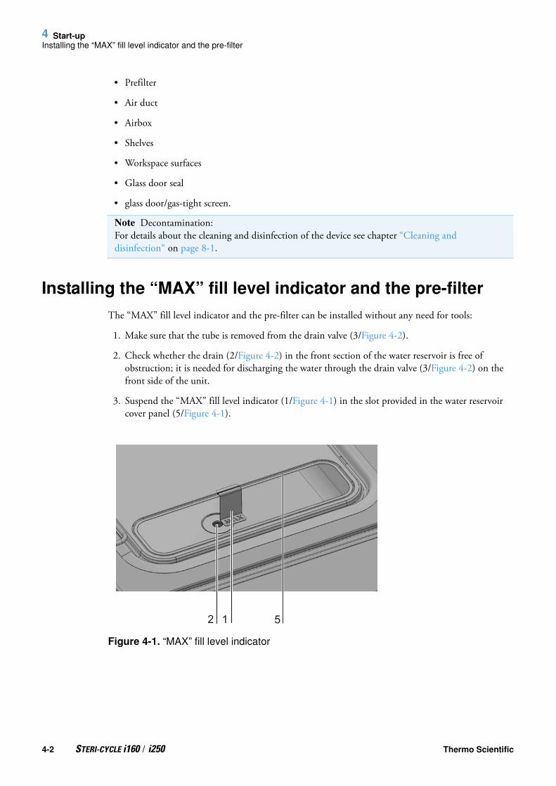
4 Start-upInstalling the “MAX” fill level indicator and the pre-filter
• Prefilter
• Air duct
• Airbox
• Shelves
• Workspace surfaces
• Glass door seal
• glass door/gas-tight screen.
Installing the “MAX” fill level indicator and the pre-filter
The “MAX” fill level indicator and the pre-filter can be installed without any need for tools:
1. Make sure that the tube is removed from the drain valve (3/Figure 4-2).
2. Check whether the drain (2/Figure 4-2) in the front section of the water reservoir is free of obstruction; it is needed for discharging the water through the drain valve (3/Figure 4-2) on the front side of the unit.
3. Suspend the “MAX” fill level indicator (1/Figure 4-1) in the slot provided in the water reservoir cover panel (5/Figure 4-1).
Figure 4-1. “MAX” fill level indicator
Note Decontamination: For details about the cleaning and disinfection of the device see chapter “Cleaning and disinfection“ on page 8-1.
12 5
4-2 STERI-CYCLE i160 / i250 Thermo Scientific

4 Start-up
Installing the “MAX” fill level indicator and the pre-filter
4. Insert the pre-filter (4/Figure 4-2) into the water reservoir cover panel.
Figure 4-2. „MAX“ fill level indicator and pre-filter
1, 2
3
4
2
2 1
Thermo Scientific STERI-CYCLE i160 / i250 4-3

4 Start-upInstall the air duct
Install the air duct1. Join the top part (1/Figure 4-3) of the air duct with the rear part (2/Figure 4-3) (see Figure 4-3, steps A-E). Make sure, that in step C of Figure 4-3 the positioning tab at the rear part clicks into place in the rectangular hole of the bottom part.
2. Place the tab at the bottom of the rear part (2/Figure 4-3) on the two rear wall studs and tilt the air duct backwards.
3. Lock the lateral keyholes of the top part (step G/Figure 4-3) into the retaining screws in the workspace ceiling.
Figure 4-3. Assembling the air duct
B C D
E G
1 2
F
4-4 STERI-CYCLE i160 / i250 Thermo Scientific

4 Start-up
Installing the HEPA-filter and the water reservoir cover panel
Installing the HEPA-filter and the water reservoir cover panel
The HEPA-filter (2/Figure 4-4) must be inserted into the airbox (1/Figure 4-4) from below. The airbox rests on the water reservoir cover panel (2/Figure 4-5) and is pushed against the air intake.
Figure 4-4. Assembling the HEPA-filter and the airbox
1. Place the HEPA-filter (2/Figure 4-4) on a flat surface.
2. Tilt the airbox (1/Figure 4-4) to the left and insert the tabs on the left (3/Figure 4-4) into the corresponding slots provided in the HEPA-filter (4/Figure 4-4).
3. Insert the tabs (5/Figure 4-4) on the right side of the airbox into the HEPA-filter catches (6/Figure 4-4).
4. Place the seal (8/Figure 4-4) into the groove (7/Figure 4-4) provided at the airbox tubing and press it down evenly.
CLICK
1
2
3
34 4
7
8
5
6
Thermo Scientific STERI-CYCLE i160 / i250 4-5

4 Start-upInstalling the HEPA-filter and the water reservoir cover panel
5. Place the airbox (1/Figure 4-5) onto its seat (2/Figure 4-5) on the water reservoir cover panel.
Figure 4-5. Place the airbox onto the Water reservoir cover panel.
6. Mount the water reservoir cover panel on the bottom of the workspace.
7. Lift the water reservoir cover at the front side and push it towards the rear wall (1/Figure 4-6).
Figure 4-6. Installing the airbox
8. Push the water reservoir cover panel all the way towards the rear wall. Doing so lets the cover panel slide into its final position in the reservoir and the tube end of the airbox into the fan outlet.
9. Let the front edge of the water reservoir cover slide into the water reservoir (2/Figure 4-6). The airbox tubing slides into the fan outlet.
1
2
1
2
11
4-6 STERI-CYCLE i160 / i250 Thermo Scientific

4 Start-up
Installing the shelf system
Installing the shelf system
Figure 4-7. Support rail installation/removal
Tools are not required for the installation of the shelf system. The support rails are secured using spring pressure. After the support hooks have been inserted into the rail, the shelves are pushed onto the support hooks.
Installation/removal of the support rail
The support rails are guided and held in place by the embossings. The locksprings of the support rails must point upwards.
1. Position the support rail onto the lower embossing and tilt it toward the workspace side wall so that the rail is positioned over the two embossings.
2. Clamp the lockspring behind the upper embossing.
3. To remove the support rails, pull the lockspring tab down out of the embossing and remove the rail.
Thermo Scientific STERI-CYCLE i160 / i250 4-7

4 Start-upInstalling the shelf system
Shelf support installation
Figure 4-8. Shelf support installation
1. Insert the shelf supports into the perforations of the support rail with the bar facing down.
2. Make sure that the two vertical elements of the shelf support are flush with the support rail.
Installing the shelves:
1. Slide the shelves tilt with the protection device (5/Figure 4-8) ahead onto the shelf support. The tilt protection is also used as a guide for the shelf.
2. Slightly raise the shelf so that the withdrawal stop (6/Figure 4-8) can be routed over the shelf supports.
3. Make sure that the shelf support is positioned in the two tilt protections in a way that allows it to move freely.
Levelling the device
1. Position a bubble level onto the center shelf or onto the roller holder.
Note With the STERI-CYCLE i160 incubator be sure to install the insert with the cut-out for refilling at the bottom position only.
4-8 STERI-CYCLE i160 / i250 Thermo Scientific

4 Start-up
Mount the split inserts (optional) into the STERI-CYCLE i250
2. Rotate the adjustable device stands using the supplied 24 mm (0.94 inch) wrench until the shelf is positioned horizontally in all directions. Perform the height adjustment of the device stands from left to right and from rear to front.
Mount the split inserts (optional) into the STERI-CYCLE i250
Figure 4-9. Installation of split inserts
For a STERI-CYCLE i250 equipped with an optional six-fold gas screen and 6-segment split inserts, three support frames with two shelves each are placed onto the shelf supports of the lateral support rails instead of the one-piece shelves of the standard version.
1. Place both these shelves (1/Figure 4-9) onto the support frame (2/Figure 4-9) (step A).
2. Suspend the support frame (2/Figure 4-9) in the shelf supports (3/Figure 4-9) (step B).
3
1
2
Thermo Scientific STERI-CYCLE i160 / i250 4-9

4 Start-upGas connection
Gas connection
Installing gas pressure hoses
Figure 4-10. Installing gas pressure hoses
The gas supply from the gas supply system to the device is established using the supplied flexible gas pressure hoses:
1. Connect the gas pressure hose to the sleeve of the gas supply system.
2. Remove the protective cap (3/Figure 4-10) from the sterile filter.
3. Slide the hose clamp (1/Figure 4-10) onto the gas pressure hose (2/Figure 4-10) and connect hose to the sleeve (4/Figure 4-10) of the sterile filter (5/Figure 4-10).
Note Gas quality:The gases must have one of the following qualities:
• Purity 99.5 % min
• medical gas quality.
CAUTION Overpressure!The operating pressure of the gas applied to the device must not exceed 1 bar (14.5 psi). If the gas is supplied at a higher pressure, the valves integral to the device may not close correctly and the gas supply control may be impaired.Set the gas supply to a range between 0.8 bar (11.6 psi) min. and 1.0 bar (14.5 psi) max. and make sure that this pressure setting cannot be changed!
4-10 STERI-CYCLE i160 / i250 Thermo Scientific

4 Start-up
Gas connection
4. Secure the gas pressure hose to the sleeve of the sterile filter using the hose clamp.
Gas connection without gas monitoring system
Figure 4-11. Gas connection without gas monitoring system
Note Pressure compensation opening:
To ensure permanent pressure compensation, the pressure compensation opening must not be connected to an exhaust air system. The pipe of the pressure compensation opening must not be extended or redirected.
Thermo Scientific STERI-CYCLE i160 / i250 4-11

4 Start-upGas connection
The gas supply from the gas supply system to the device is established using the supplied flexible gas pressure hoses:
CO2 connection:
• For a device with CO2 connection, connect the gas supply to the gas inlet filter (2/Figure 4-11) in accordance with the connection diagram (1/Figure 4-11).
Combined CO2 and O2-/N2 connection (optional):
On units with a combined CO2 /O2 /N2 connection, the gas supply tubes must be routed according to the following connection diagram (3/Figure 4-11):
• Connect the O2/N2 supply line to the upper gas inlet filter (4/Figure 4-11),
• connect the CO2 supply line to the lower gas inlet filter (5/Figure 4-11).
CO2 connection with gas monitoring system (optional)
Figure 4-12. CO2 connection with gas monitoring system (optional)
Note Manual gas monitoring:
On devices without the optional gas monitoring system, there is no automatic gas monitoring.Therefore, the filling level of the gas bottles must be checked every day.
4-12 STERI-CYCLE i160 / i250 Thermo Scientific

4 Start-up
Gas connection
The supplied gas pressure hoses feed the gas from the central gas supply system to the device.Devices with CO2 connections that are equipped with the optional gas monitoring system are
connected according to the connection diagram (7/Figure 4-12).
CO2 connection:
For a device that is operated with process gas CO2 and equipped with the optional gas monitoring system, connect the gas supply lines as follows:
• Item 1/Figure 4-12: Distributor connection for the CO2 gas supply for up to three additional devices. For looping the gas supply through, the devices must be interconnected with a gas pressure hose.
• Item 2/Figure 4-12: Connect the gas container B to the upper connection of the gas monitoring system.
• Item 3/Figure 4-12: Connect the gas container A to the lower connection of the gas monitoring system.
• Items 4 & 5/Figure 4-12: The outlet of the gas monitoring system is connected at the factory to the gas inlet filter by a short gas pressure hose (item 6/Figure 4-12).
Combined CO2 and O2/N2 connection with gas monitoring system (optional)
Figure 4-13. Combined CO2/O2/N2 connection with gas monitoring system (optional)
Note Looping the gas supply through:By looping the gas supply through, up to 4 devices can be supplied by a CO2 gas supply.
Thermo Scientific STERI-CYCLE i160 / i250 4-13

4 Start-upGas connection
The supplied gas pressure hoses feed the gas from the central gas supply system to the device.
Devices with combined CO2/O2/N2 connections that are equipped with the optional gas monitoring system are connected according to the connection diagram (10/Figure 4-13).
O2/N2 supply:
• Distributor connection for the O2-/N2 gas supply for up to three additional devices (hidden in Figure 4-13). For looping the gas supply through, the devices must be interconnected with a gas pressure hose.
• Item 2/Figure 4-13: Connect the gas container B to the connection of the gas monitoring system,
• Item 3/Figure 4-13: Connect the gas container A to the connection of the gas monitoring system.
• Item 1/Figure 4-13: The outlet of the gas monitoring system is connected at the factory to the gas inlet filter (item 8/Figure 4-13) by a short gas pressure hose.
CO2 supply:
• Item 4/: Distributor connection for the CO Figure 4-132 gas supply for up to three additional devices. For looping the gas supply through, the devices must be interconnected with a gas pressure hose.
• Item 5/Figure 4-13: Connect the gas container B to the connection of the gas monitoring system,
• Item 6/Figure 4-13: Connect the gas container A to the connection of the gas monitoring system.
• Item 7/Figure 4-13: The outlet of the gas monitoring system is connected at the factory to the gas inlet filter by a short gas pressure hose.
Note Looping the gas supply through:
By looping the gas supply through, up to 4 devices (independent of device type) can be supplied by a CO2 gas supply or a O2-/N2 gas supply.
4-14 STERI-CYCLE i160 / i250 Thermo Scientific

4 Start-up
Power supply connection
Power supply connection
Figure 4-14. Power supply connection
Connect the unit to a correctly installed and grounded power supply source fused with a B 16 circuit breaker.
Connection to the power supply system:
1. Before connecting the device to the power supply, check to see if the voltage of the power outlet corresponds with the specifications on the nameplate to the left of the power switch. If the ratings given for voltage (V) and current (A) are not correct, the device must not be connected to the power supply.
2. Connect the IEC connector to the socket of the control box of the device.
3. Connect the grounding plug of the power supply cable to a correctly grounded and fused socket.
4. Make sure the power supply cable is not subjected to tensile or compressive force.
5. Mains connection: The mains socket must be easily identifiable by the user and freely accessible at all times. The power cord plug is the all-pole disconnecting device from the mains supply.
WARNING Electric shock!Contact with current-carrying components may cause a lethal electric shock. Before connecting the device to the power supply, check plug and power supply cable for damage.Do not use damaged components when connecting the device to the power supply!
Thermo Scientific STERI-CYCLE i160 / i250 4-15

4 Start-upConnecting the USB interface:
Connecting the USB interface:
The units come equipped with a USB interface as a standard feature. The connection to the PC is made using a commercially available USB 1 or USB 2 cable (incubator side: USB male connector of Type B, PC side: USB male connector of Type A.
The USB interface complies with Standard USB 1.1 and is compatible with Standard USB 2.0 and 3.0 (full speed). Data communication between the PC and incubator across the USB interface requires that suitable driver software be installed on the PC, unless such software is provided by the currently installed Windows-version. The installation of the driver software is described in “Annex: Data communication“ on page 12-1.
The bit rate of the interface can be changed within the pre-set Baud rates limits (9.600, 19.200, 38.400, 57.600 Baud). Baud rate adjustment is described in section “USB interface baud rate setting“ on page 6-23.
Connecting the alarm contact:
Function:When system errors and failures occur in the temperature or gas control circuits, an alarm message is issued to the connected alarm/monitoring system. The potential-free contact (1 changeover contact) has been designed for the following circuits:
Alarm relay:
Note Skilled work:Thermo Scientific warrants the operational safety and the operativeness of the device only if installation and repairs are performed properly.The connection of the device to an external alarm system must only be carried out by adequately trained and authorized expert electrical/telecommunication personnel!
Circuit Mains Voltage External fusing
Circuits with AC mains voltage
250 V ~ max. 6 A max.
SELV – circuits (cf. VDE 0100, part 410)
25 V ~ 2 A max.
60 V = 1 A max.
SELV E – circuits (cf. VDE 0100, part 410)
50 V ~ 1 A max.
120 V = 0.5 A max.
Operating states Contact 3 - 2 Contact 3 - 1
Operating state power failure “OFF”
X O
Operating state power failure “ON”
..% o X
Error power failure “OFF”
..% o X
4-16 STERI-CYCLE i160 / i250 Thermo Scientific

4 Start-up
Connecting the alarm contact:
Connection example:
Figure 4-15. Connection example alarm contact
The connector for connecting the interface cable is not included in the scope of delivery and must be ordered separately. Specifications for the operating voltage and the fusing of external alarm circuitry are given in the table above.
1. Wire the individual conductors as shown in the wiring diagram.
2. Connect the connector of the alarm system connecting cable to the interface at the control box at the rear panel of the device.
Error power failure “ON”
X ..% o
Key: X: Contact closed / O: Contact open
Note Switching structure:The alarm relay switches for all failures reported by the control loops (see “Error messages“ on page 6-45).
Operating states Contact 3 - 2 Contact 3 - 1
Thermo Scientific STERI-CYCLE i160 / i250 4-17

4 Start-upConnecting the 4-20 mA interface:
Connecting the 4-20 mA interface:
The following illustration shows the pin-out of the 4-20mA data interface:
Figure 4-16. Pin-out of the 4-20 mA interface
Retrofitting of the 4-20 mA data interface is reserved exclusively to Thermo Fisher Scientific Technical Field Service staff.
Note Skilled work:Thermo Scientific warrants the operational safety and the operativeness of the device only if installation and repairs are performed properly.The connection of the device to an external alarm system must only be carried out by adequately trained and authorized expert electrical/telecommunication personnel!
4-18 STERI-CYCLE i160 / i250 Thermo Scientific

5
Operation
Preparing the device
The device must not be released for operation before all major start-up activities (see “Start-up“ on page 4-1) have been completed.
Device check:
Prior to starting operation, the following device components must be checked for their correct function
• Gas hoses must be seated tight on the connecting filter and must be secured using a hose clamp.
• The access port must be capped.
• The pressure compensation opening must be permeable, its insert must be installed in the workspace.
• The glass door seal must not be damaged.
• The glass door/gas-tight screen measurement opening must be capped.
• The shelf system components must be installed safely.
• The airbox with the HEPA-filter and the air duct must be installed according to the instructions.
Decontaminating the device workspace:
• Run the steri-run decontamination routine (see “Steri-run decontamination routine“ on page 8-7) or decontaminate the workspace according to the hygiene regulations set forth by the operator.
Table of Contents
• “Preparing the device“ on page 5-1
• “Starting operation“ on page 5-3
Thermo Scientific STERI-CYCLE i160 / i250 5-1

5 OperationPreparing the device
Fill volume for STERI-CYCLE i160 and STERI-CYCLE i250: 3 l
Note Hygiene regulations:Prior to any operation, the user must clean and disinfect the workspace in accordance with the hygiene regulations set forth by the operator to protect the cultures.
Water supply: see “Relative humidity:“ on page 3-7.
When the filling level drops below a minimum value, it must be possible to top up water during the work process.
5-2 STERI-CYCLE i160 / i250 Thermo Scientific

5 Operation
Starting operation
Starting operation1. Open glass door or gas-tight screen.
2. Remove pre-filter (2/Figure 5-1).
3. Insert with cut-out for refilling (STERI-CYCLE i160 ): Open flap (3/Figure 5-1).Single-piece insert (STERI-CYCLE i250): Remove bottom insert if there is not enough space for the container used for filling.
4. Fill reservoir with sufficiently purified water (beneath cover item 1 in Figure 5-1) of the workspace.
Figure 5-1. Water reservoir
1
2
1
2
3
Thermo Scientific STERI-CYCLE i160 / i250 5-3

5 OperationStarting operation
5. Do not exceed the maximum level mark “MAX” (1/Figure 5-2). The maximum fill volume of the water reservoir (5/Figure 5-2) is 3 l.
Figure 5-2. “MAX” fill level indicator
6. Wipe off excess water from the cover of the water reservoir.
7. Reinstall pre-filter (2/Figure 5-1).
8. Reinstall the bottom shelf or close flap over cut-out for filling.
9. Make sure that the valves of the CO2 /O2 /N2 supply system are open.
10. Turn on the device using the power switch.
11. Adjust set values for temperature and CO2 /O2 concentration on the iCan™ touchscreen.
Starting the device:
12. Start the device with the auto-start routine (see “Activating the auto-start routine“ on page 6-14).
13. The auto-start progress indicator appears on the display, and the automatic start routine is run.
14. The temperature control adjusts the temperature to the selected set value, humidity rises.
15. When temperature and relative humidity are constant, the automatic adjustment of the CO2-/O2 measuring system is performed.
16. The CO2-/O2 control supplies the set amount of CO2-/O2.
17. If the auto-start routine has been completed, the progress indicator is hidden, and the main menu is displayed. The device is operational.
12 5
5-4 STERI-CYCLE i160 / i250 Thermo Scientific

5 Operation
Starting operation
Loading the device:
18. Load the workspace with cultures.
Note
Duration of the auto-start routine:When the device is cold and when the ambient temperature is low, the auto-start routine may take up to 10 hours.
Loading:To ensure sufficient air circulation and even heating of the samples, the loading surface within the workspace should be used up to 70% max. Bulky objects in the workspace that dissipate heat may impair heat distribution. Bulky objects in the use able space that dissipate heat may impair heat distribution.
Thermo Scientific STERI-CYCLE i160 / i250 5-5

5 OperationStarting operation
5-6 STERI-CYCLE i160 / i250 Thermo Scientific

6
Handling and control
Table of Contents
• “Power switch“ on page 6-2
• “Operating panel and operating structure“ on page 6-3
• “Factory presettings of the iCan™ Touchscreen controls“ on page 6-7
• “Heat-up phase of the control loop sensors“ on page 6-7
• “Behavior of keys during adjustments“ on page 6-8
• “Setting the temperature set value“ on page 6-8
• “Setting the CO2 set value“ on page 6-9
• “Setting the O2 set value“ on page 6-10
• “auto-start function“ on page 6-12
• “Launching steri-run“ on page 6-16
• “User configuration“ on page 6-17
• “Trend display scaling“ on page 6-43
• “Error messages“ on page 6-45
• “Measures after power outage“ on page 6-47
Thermo Scientific STERI-CYCLE i160 / i250 6-1

6 Handling and controlPower switch
Power switch
Figure 6-1. Power switch
The power switch is mounted in the side panel of the unit.
• Powering up: Press the power switch; the switch illumination comes on.
• After a short beep the blank screen vanishes and the touchscreen is displayed.
• The control loop sensors pass the heat-up phase (“Heat-up phase of the control loop sensors“ on page 6-7).
• Powering down: Press the power switch; the switch illumination goes off.
6-2 STERI-CYCLE i160 / i250 Thermo Scientific

6 Handling and control
Operating panel and operating structure
Operating panel and operating structure
The control panel works as a touchscreen (iCan™ Touchscreen) and can be controlled performing light pressure using a finger or a blunt pin.
Figure 6-2. Main screen: Touch-sensitive screen areas
The following screen areas of the operating panel are touch-sensitive and accept operating commands:
• Temperature display T,
• CO2 display CO2,
• Display field water level RH,
• O2 display (optional),
• Icon bar with symbolic representations of operating states, allowing direct access to installed options (see also “Icon description“ on page 6-40),
• steri-run key,
• Menu key,
• auto-start key.,
Note Extended pressure-sensitive area:To accept a failure message, the entire touchscreen can be used as a pressure-sensitive area.
Thermo Scientific STERI-CYCLE i160 / i250 6-3

6 Handling and controlOperating panel and operating structure
Versions without O2/N2 control
Figure 6-3. iCan™ Touchscreen without O2/N2 gas supply
Function keys and actual value readouts on the operating panel for versions without O2/N2 gas supply source:
1. Workspace temperature display field with actual value (large numeric readout at center), set value (small numeric readout top right) and physical unit (bottom right)
2. CO2 concentration display field with actual value (large numeric readout at center), set value (small numeric readout top right) and physical unit (bottom right)
3. HEPA-filter activity display (icons for further options see “Icon description“ on page 6-40)
4. Key for starting the steri-run decontamination routine
5. Key for opening the menu navigation
6. Key for starting the auto-start routine
7. Display field water level RH
6-4 STERI-CYCLE i160 / i250 Thermo Scientific

6 Handling and control
Operating panel and operating structure
Version with combined CO2/O2/N2 control (optional)
Figure 6-4. iCan™ Touchscreen with combined gas connection
Function keys and actual value readouts on the operating panel for versions with a combined CO2/O2/N2 gas supply source:
1. Workspace temperature display field with actual value (large numeric readout at center), set value (small numeric readout top right) and unit (bottom right)
2. CO2 concentration display field with actual value (large numeric readout at center), set value (small numeric readout top right) and unit (bottom right)
3. HEPA-filter activity display (icons for further options see “Icon description“ on page 6-40)
4. Key for starting the steri-run decontamination routine
5. Key for opening the menu navigation
6. Key for starting the auto-start routine
7. O2 concentration display field with actual value (large numeric readout at center), set value (small numeric readout top right) and physical unit (bottom right)
8. Display field water level RH
Structure of the operating levels
Operation is divided into three levels:
• A: Direct access to the control loop settings: Temperature, CO2, O2-setpoint,
• B: Starting the Steri-Run or auto-start routine of the unit,
• C: Navigation through the submenus for device configuration.
Thermo Scientific STERI-CYCLE i160 / i250 6-5

6 Handling and controlOperating panel and operating structure
Figure 6-5. Menu structure overview
A
B
C
6-6 STERI-CYCLE i160 / i250 Thermo Scientific

6 Handling and control
Factory presettings of the iCan™ Touchscreen controls
Factory presettings of the iCan™ Touchscreen controls
Upon delivery of the device, the following set values have been preset:
• Temperature: 37 °C
• CO2-content: 5,0 %
• O2-content (optional): 21,0 %
Heat-up phase of the control loop sensors
When the device has been switched on, the control loop sensors pass through a heat-up phase of varying duration during the start process:
1. Temperature control loop: 10 s
2. CO2 sensor heat-up period (TCD and IR): 5 min
3. O2 control loop: 5 min
Figure 6-6. Heat-up phase display
The start process is indicated by an audible signal. During the heat-up phase, the displays show dots (...) instead of values:
• Temperature display,
• CO2 display and
• O2 display field
Note CO2-/O2 control:Since the CO2 concentration of the air is nearly 0%, the CO2 control and the control loop error monitoring system are disabled at a set value of 0%.Since the O2 concentration of the air is 21%, the O2 control and the control loop error monitoring system are disabled at a set value of 21%.
Thermo Scientific STERI-CYCLE i160 / i250 6-7

6 Handling and controlBehavior of keys during adjustments
After the heat-up phase has been completed, the control loop actual values are indicated.
Behavior of keys during adjustments
Pressing a key can increase or reduce a value gradually:
• Keeping the “–“ or “+” key depressed switches to rapid scan mode,
• after the key has been kept depressed for more than 3 seconds, the quick run speed increases.
Setting the temperature set value1. Press the Temperature key.• The Temperature menu (Figure 6-7) is displayed.
Figure 6-7. Temperature display field and temperature selection menu
2. To exit the Temperature menu:• Press the End key [3].
3. To set the temperature set value:• Press the Set value key.
Note CO2 gas supply:During the 5-minute heat-up phase of the O2 control circuit, the CO2 supply to the workspace and monitoring of the CO2 control circuit are suspended.
Note Saving the settings:To save changed values, press the Enter key.
Resetting the settings:Unless a user action (contact with the pressure-sensitive areas and keys) occurs within 30 seconds, the system automatically exits the menu and the most recently confirmed setting defaults.
6-8 STERI-CYCLE i160 / i250 Thermo Scientific

6 Handling and control
Setting the CO2 set value
Figure 6-8. Setting the temperature set value
To increase the set value:• Press the + key.
To reduce the set value:• Press the - key.
4. To accept and save the set value:• Press the Enter key.• The system returns to the main menu. The temperature displays shows the actual value currently measured in the workspace.
Setting the CO2 set value1. Press the CO2 display key.• The CO2 menu is displayed.
Figure 6-9. CO2 display and CO2 menu
2. To exit the CO2 menu:• Press the End key [3].
Thermo Scientific STERI-CYCLE i160 / i250 6-9

6 Handling and controlSetting the O2 set value
3. To set the CO2 set value:• Press the Set value key.
To increase the set value:• Press the + key.
To reduce the set value:• Press the - key.
4. To accept and save the set value:• Press the Enter key.• The system returns to the main menu. The CO2 display shows the actual value currently measured in the workspace.
Figure 6-10. Setting the CO2 set value
Setting the O2 set value
This setting is possible only on versions with the optional O2-/N2 control.
1. Press the O2 display key.• The O2 menu is displayed.
Note Deactivating the CO2 control loop:To deactivate the CO2 control, the set value is set to 0 %.If the control loop is deactivated, error monitoring is enabled as well.
Gas monitoring:The switching state of the CO2 control loop does not affect the function of the optional gas monitoring system. The gas monitoring system remains active even when the CO2 control is switched off.
6-10 STERI-CYCLE i160 / i250 Thermo Scientific

6 Handling and control
Setting the O2 set value
Figure 6-11. O2 display and O2 menu
2. To exit the O2 menu:• Press the End key.
3. To set the O2 set value:• Press the Set value key.
To increase the set value:• Press the + key.
To reduce the set value:• Press the - key.
4. To accept and save the set value:• Press the Enter key.• The system returns to the main menu. The O2 display shows the actual value currently measured in the workspace.
Figure 6-12. Setting the O2 set value
Thermo Scientific STERI-CYCLE i160 / i250 6-11
6 Handling and controlauto-start function
auto-start function
The auto-start function is a fully automated routine for startup and subsequent adjustment of the CO2 sensing circuits. After the start, the device control adjusts the temperature to the set value while humidity is generated. When temperature and relative humidity have reached constant values, the CO2 measuring system is automatically adjusted to these values, and the workspace is supplied with the preset quantity of CO2.
Note Factory settings:Depending on the type of the O2 sensor, one of the two O2 control ranges has been preset at the factory:Control range I: 1 % - 21 %Control range II: 5 % - 90 %
Usage of the process gases:
For set values below 21 % O2, the device must be connected to a nitrogen supply system.For set values above 21 % O2, the device must be connected to an oxygen supply system.For set values of 21 % O2, the O2 control is switched off and error monitoring is disabled as well. The control loop error monitoring system (optional) is enabled.
Note
Please make sure that the sensor has been correctly plugged into the socket. Improper installation of the sensor may cause corrosion at the contacts and calibration errors during the auto-start routine. You can verify the proper function by simply activating the sensor. When no error message occurs within 10 minutes, the unit is ready for the auto-start routine.
6-12 STERI-CYCLE i160 / i250 Thermo Scientific

6 Handling and control
auto-start function
Notes on using the auto-start routine:
To ensure that the specified accuracy of the CO2 measuring system is maintained, the device should always be started using the auto-start routine if:
• a difference of more than 1 °C is entered upon setting the temperature set value,
• the Low Humidity function is enabled/disabled,
• the device is restarted after an extended interruption of operation.
The auto-start routine should be run at least every three months on the occasion of cleaning and maintenance works.
Duration of the auto-start routine:
Running the auto-start-routine usually takes 5 to 7 hours. At low room temperatures and when the device is cold, it may take up to 10 hours until the auto-start routine has been completed. If the glass door is opened or if the power supply of the device is interrupted while the auto-start routine is running, the routine is interrupted and rerun after the glass door has been closed or the power supply has been reestablished.
Start conditions for the auto-start routine:
Prior to running the auto-start routine, set the CO2 and O2 set values to the desired values and make sure that the atmosphere in the work space only consists of ambient air. The water reservoir in the workspace must be filled sufficiently with water.
Inhibition of the auto-start routine:
The auto-start routine will not start if any of the following error conditions exists.
Temperature control loop:
• Sensor breakage,
• Actual value high, exceeding set value (excessive deviation),
• Actual value low, falling short of set value (excessive deviation),
• Actual value not plausible
• calibration values too high or too low,
• No communication with sensor.
Gas supply CO2 control loop:
• No communication with sensor.In this case, the auto-start key is dimmed and its function is not available.
Thermo Scientific STERI-CYCLE i160 / i250 6-13

6 Handling and controlauto-start function
Activating the auto-start routine
Preparations for the start:
1. Make sure that the valves of the CO2 /O2 /N2 gas supply system are open.
2. Fill the reservoir with purified water. Do not exceed the upper level mark.
Launching the auto-start routine:
1. Press the auto-start key.• The auto-start instruction menu is displayed.
Figure 6-13. Activating the auto-start routine
2. To exit from the auto-start instruction menu and stop auto-start:• Press the End key [3].
3. Refill water, if necessary.
4. Activate the auto-start routine:• Press the Start key.
5. To air the workspace, open both device doors. When the audible alarm sounds after 30 seconds,
Auto-start routine aborted due to error:
The auto-start routine is aborted if:
• an error is detected in the temperature control loop,
• an error is sensed in the CO2 control circuit,
• the water filling level is insufficient,
• the CO2 value to be set is out of tolerance.
Dry execution of auto-start routine:
If the routine is to be run dry (without water in the water reservoir of the workspace), the water level sensor must be disabled prior to its start (chapter “Options“ on page 6-31).
6-14 STERI-CYCLE i160 / i250 Thermo Scientific

6 Handling and control
auto-start function
6. close both device doors.• A status display window showing data on the process is displayed.
Figure 6-14. auto-start-status display window
Interrupting the auto-start routine
If the Stop key in the status display is depressed, the auto-start routine is interrupted and the auto-start stop dialog box is displayed for a safety scan. The routine can now be permanently cancelled or resumed.
1. To resume the auto-start routine:• Press the Back key.• The system returns to the status display, and the auto-start routine is resumed.
2. To cancel the auto-start routine:• Press the End key [3].• The warning triangle is displayed as a failure message together with the audible signal.
Note Cancellation:The auto-start routine can be cancelled at any time!Press the Stop key.
Automatic restart:The auto-start routine is restarted automatically if the routine is cancelled due to one of the following events:
• The glass door is opened,
• the outer door is opened on a device with optional gas-tight screen,
• the power supply is interrupted.
Thermo Scientific STERI-CYCLE i160 / i250 6-15

6 Handling and controlLaunching steri-run
Figure 6-15. Interrupting the auto-start routine
3. To accept the failure message:• Press any position on the display.• The Error dialog box with the description of the error is displayed.
Figure 6-16. Error message subsequent to aborted auto-start
4. To accept the failure message:• Press the End key [3].• The system returns to the main menu.
Launching steri-run
The steri-run decontamination routine is used to decontaminate the complete workspace. An in-depth description of the function is given in the chapter Cleaning and disinfection (Chapter 8‚ page 1).
6-16 STERI-CYCLE i160 / i250 Thermo Scientific

6 Handling and control
User configuration
User configuration
The user configuration settings allow the user interface and the additional device functions to be adjusted to the requirements of everyday operation.The user configuration selection menu (Figure 6-17) is invoked by pressing the Menu key on the main screen.
Figure 6-17. User configuration menu
The user configuration menu is split into six categories:• Settings,• Event logging,• Options,• Icon description,• Keypad lock,• Software versions.
To make a user-specific setting in a dialog box, navigate through the submenus listed in the illustrations and open the dialog box.
Settings / Setup
The Settings selection menu (Figure 6-18) allows for accessing a series of dialog windows with adjustment options for customizing the user interface:• Changing the keypad lock code,• Date/time setting,• Adjusting display brightness,• Key tone setting,• Interface configuration,• User display screen language setting,• Reminder interval setting.
Thermo Scientific STERI-CYCLE i160 / i250 6-17

6 Handling and controlUser configuration
Figure 6-18. Settings/Setup menu
Changing the keypad lock code
The keypad lock prevents the unauthorized changing of the operational settings. Only those keys are locked where values can be entered.The keypad is locked by entering four numbers.
• Upon delivery, the default code is: 0000.
This default can be changed into a user-defined code that is then enabled using the KEYPAD LOCK dialog box (“Enabling/disabling the keypad lock“ on page 6-42).
Changing the keypad lock code:
1. Press the Menu key.
2. Select the menu command Keypad lock code.• The input dialog shown in Figure 6-19 is displayed.
Figure 6-19. Changing the keypad lock code
3. To enter the default 0000:• Press the corresponding numeric keys.• The number combination is displayed as encrypted text in the input box.
6-18 STERI-CYCLE i160 / i250 Thermo Scientific

6 Handling and control
User configuration
4. Confirm your input:• Press the Enter key.• The Code new prompt appears in the display. Four blanks indicate that a new key code may be entered.
Figure 6-20. Changing the keypad lock code
Entering the new 4-digit code:• Press the corresponding numeric keys.• The number combination is displayed in the input box.
5. To set the cursor to the left to overwrite a value:• Press the Backspace (<<) key.
6. To accept and save the input value:• Press the Enter key.• The system returns to the Settings/Setup menu.• A padlock icon appears on the Icon bar in the main menu (Figure 6-2 on page 3) as an activity indicator for the keypad lock.
Date/time setting
The input dialog allows date and time to be set to the required time zone.
1. Press the Menu key.
2. Select the menu command Date / Time.• The selection dialog shown in Figure 6-21 is displayed.
Note Changing the user-defined code:The user-defined code can be changed as often as required using the same procedure:
• Activate the recoding function by entering the valid code,
• enter the new code and confirm it.
Thermo Scientific STERI-CYCLE i160 / i250 6-19

6 Handling and controlUser configuration
Figure 6-21. Date/Time menu
3. For changing the date, choose the Date option.• The input dialog shown in Figure 6-22 is displayed.
Figure 6-22. Setting the date
4. To enter the date:• Press the numeric keys.• The input numbers are displayed in the input box.
5. To set the cursor to the left to overwrite a value:• Press the Backspace (<<) key.
6. To accept and save the input value:• Press the Enter key.
7. The system returns to the Date/Time menu.
8. For changing the time, choose the Time option.• The input dialog shown in Figure 6-23 is displayed.
6-20 STERI-CYCLE i160 / i250 Thermo Scientific

6 Handling and control
User configuration
Figure 6-23. Setting the time
9. To enter the time:• Press the numeric keys.• The input numbers are displayed in the input box.
10. To set the cursor to the left to overwrite a value:• Press the Backspace (<<) key.
11. To accept and save the input value:• Press the Enter key.
12. The system returns to the Date/Time menu.
Adjusting display brightness
The selection menu allows for adjusting the brightness of the operating panel over a range from 1 to 100 %.
Setting the contrast
1. Press the Menu key.
2. Select the menu command Settings / Setup.
3. Select the option Display contrast.• The input dialog shown in Figure 6-24 is displayed.
Thermo Scientific STERI-CYCLE i160 / i250 6-21

6 Handling and controlUser configuration
Figure 6-24. Adjusting display brightness
4. To increase the value:• Press the + key.
5. To reduce the value:• Press the - key.
6. The value change appears in the display. The New message indicates that the selection has been changed, but not saved yet.
7. To accept and save the change:• Press the Enter key.• The system returns to the Settings/Setup menu.
Key tone setting
The input dialog allows the loudness of the key tone that sounds whenever a key is depressed to be set.The value range is 0 to 100. The change occurs in increments of 5.
Adjusting key tone volume
1. Press the Menu key.
2. Select the menu command Settings / Setup.
3. Select the option Key tones.• The input dialog shown in Figure 6-25 is displayed.
6-22 STERI-CYCLE i160 / i250 Thermo Scientific

6 Handling and control
User configuration
Figure 6-25. Adjusting key tone volume
1. To increase the value:• Press the + key.
2. To reduce the value:• Press the - key.
3. The value change appears in the display. The New message indicates that the selection has been changed, but not saved yet.
4. To accept and save the change:• Press the Enter key.• The system returns to the Settings/Setup menu.
USB interface baud rate setting
This selection menu allows for adjusting the data rate of the USB interface:
The baud rate can be changed within the defined baud rates (9,600, 19,200, 38,400, 57,600 baud).
Setting the baud rate
1. Press the Menu key.
2. Select the menu command Settings / Setup.• The selection dialog shown in Figure 6-26 is displayed.
Thermo Scientific STERI-CYCLE i160 / i250 6-23

6 Handling and controlUser configuration
Figure 6-26. Interface USB menu
3. Select the option Interface USB (Figure 6-26).• The input dialog shown in Figure 6-27 is displayed.
Figure 6-27. USB interface baud rate setting
4. Press the + or key to set the Baud rate of the USB interface (Figure 6-27).• To increase the baud rate: Press the + key.• To reduce the baud rate: Press the - key.
5. The value change appears in the display. The New message indicates that the selection has been changed, but not saved yet.
6. To accept and save the change:• Press the Enter key.• The display returns to Interface USB selection menu.
7. To activate the new settings:• Browse back to the main menu.• Wait for approx. 10 seconds and perform a reset by switching the device off and on using the power switch.
6-24 STERI-CYCLE i160 / i250 Thermo Scientific

6 Handling and control
User configuration
Setting the language of the display screen
The input dialog allows the language of the display screen to be set. Seven languages are available:• German,• English,• Spanish,• French,• Italian,• Chinese,• Japanese.
Selecting the display language:
1. Press the Menu key.
2. Select the menu command Language.• The input dialog shown in Figure 6-28 is displayed.
Figure 6-28. Language setting
3. To browse upward in the selection:• Press the + key.
4. To browse downward in the selection:• Press the - key.
5. The new language appears in the display. The New message indicates that the selection has been changed, but not saved yet.
6. To accept and save the selection:• Press the Enter key.• The system returns to the Settings/Setup menu.
Thermo Scientific STERI-CYCLE i160 / i250 6-25

6 Handling and controlUser configuration
Reminder interval setting
The reminder intervals are integral components of the alarm and monitoring system of the device control. For the two essential functions steri-run and auto-start as well as for routine service work, the user can set dates that trigger an alarm whenever they occur. The counting begins at 00:00 hrs of the day on which the previously set reminder interval has elapsed.
On the due date, the display shows a reminder message for the activated reminder interval:• Steri-run: Please run Steri-Run routine.• auto-start: Please run auto-start routine. Appears upon successful completion of the Steri-Run decontamination routine.
• Service interval: Request service. The service message can be confirmed. In this case, the Request Service icon is displayed.
After the routines have been run successfully, the reminder messages are hidden.
Factory settings
Steri-run decontamination routine 90 daysauto-start routine OffService interval OffHEPA interval 365 days
Reminder interval setting
1. Press the Menu key.
2. Select the Reminder intervals menu option.• The selection dialog shown in Figure 6-29 is displayed.
Figure 6-29. Choose the desired reminder interval function.
3. Select the appropriate menu option, for example Steri-run.• The input dialog shown in Figure 6-29 is displayed.
6-26 STERI-CYCLE i160 / i250 Thermo Scientific

6 Handling and control
User configuration
Figure 6-30. Setting the reminder interval for steri-run
1. To increase the number of days:• Press the + key.
2. To reduce the number of days:• Press the - key.
3. The value change appears in the display. The New message indicates that the selection has been changed, but not saved yet.
4. To deactivate the reminder interval:• Set the value to Off.• Press the - key.
5. To accept and save the change:• Press the Enter key.• The display returns to the reminder intervals selection menu.
Data Logging
The Event logging selection menu (Figure 6-31) allows for accessing dialog screens for logging and displaying events that occur during ongoing operation of the unit:• Event display,• Recording interval,• Error table.
Thermo Scientific STERI-CYCLE i160 / i250 6-27

6 Handling and controlUser configuration
Figure 6-31. Event logging menu
Event display
The event display uses short, single-line entries specifying date and time to report the events that were logged during the operation of the device.The entries are listed in chronological order with the most recent event at the top position. The list can be displayed but not edited. If the event display consists of several pages, the user can browse through the list. The status indicator indicates which page of the total number of pages is currently being displayed.
Invoking the event log
1. Press the Menu key.
2. Select the menu command Event logging.• The selection dialog shown in Figure 6-31 is displayed.
3. Select the menu command Event display.• The list shown in Figure 6-32 appears on the display.
Figure 6-32. Event display
6-28 STERI-CYCLE i160 / i250 Thermo Scientific

6 Handling and control
User configuration
1. To browse forward in the list:• Press the Continue key.
2. To browse backward in the list:• Press the Previous key.
3. Exit the display:• Press the End key [3].• The system returns to the Event logging menu.
Changing the logging cycle time:
Due to limited memory resources, the oldest entries are deleted as new entries are logged. The period from which the displayed entries originate depends largely on the selected logging cycle time.
Invoking the event log
1. Press the Menu key.
2. Select the menu command Event logging.• The selection dialog shown in Figure 6-31 is displayed.
3. Select the menu command Recording interval.• The input dialog shown in Figure 6-33 is displayed.
Figure 6-33. Logging cycle setting
Thermo Scientific STERI-CYCLE i160 / i250 6-29

6 Handling and controlUser configuration
The setting controls the logging cycle in sections of seconds during which the control loop measured values are logged during the operation of the device and displayed by the trend display (“Trend display scaling“ on page 6-43).
The settings can be made within the value range of 10 seconds to 3600 seconds.
1. To increase the value:• Press the + key.
2. To reduce the value:• Press the - key.
3. The value change appears in the display. The New message indicates that the selection has been changed, but not saved yet.
4. To accept and save the change:• Press the Enter key.• The system returns to the Event logging menu.
Displaying the error table
The error table lists the errors detected by the device-integral monitoring system in descending chronological order. The most recently detected error is listed at the top position of 22 possible entries. An entry consists of the control loop in which the error occurred, the date, the time, and an error description. The error table can be displayed but not edited. If the event display consists of two pages, the user can browse through the list. The status indicator 001/002 or 002/002 indicates which page of the two pages is currently being displayed.
Displaying the error table
1. Press the Menu key.
2. Select the menu command Event logging.• The selection dialog shown in Figure 6-31 is displayed.
3. Select the menu command Event display.• The list shown in Figure 6-34 appears on the display.
Logging cycle Maximum period displayed
10 s 22.5 hours
30 s 2.8 days
60 s 5.6 days
120 s 11.2 days
180 s 16.8 days
3600 s 336 days
Note Event logger interval time: The logging cycle time does not affect the entries of the error table.
6-30 STERI-CYCLE i160 / i250 Thermo Scientific

6 Handling and control
User configuration
Figure 6-34. Displaying the error table
1. To browse forward in the error table:• Press the Continue key.
2. To browse backward in the list:• Press the Previous key.
3. Exit the display:• Press the End key [3].• The system returns to the Event logging menu.
Options
The Options selection menu (Figure 6-35) allows for accessing all selection dialogs for the functional options of the unit:• Alarm,• Low humidity,• Gas-tight screen (optional),• Humidity sensor,• Audible alarm,• O2 gas supply (optional),• HEPA-filter.
Note Troubleshooting:For a detailed overview of causes for errors and their correction, please refer to the end of this chapter!
Thermo Scientific STERI-CYCLE i160 / i250 6-31

6 Handling and controlUser configuration
Figure 6-35. Options menu
Alarm relay setting
The alarm relay is the electrical interface for wiring the internal control subsystem of the unit to an external power monitoring system. Depending on the required input signal of the external monitoring system, network monitoring can be enabled or disabled. If network monitoring is enabled, a power failure is detected as an error. Wiring details for the alarm relay are described in the section“Connecting the alarm contact:“ on page 4-16.
1. Press the Menu key.
2. Select the menu command Options.• The selection dialog shown in Figure 6-35 is displayed.
3. Select the menu command Alarm.• The selection dialog shown in Figure 6-36 is displayed.
Figure 6-36. Alarm menu
4. Select the menu command Alarm relay.• The input dialog shown in Figure 6-37 is displayed.
6-32 STERI-CYCLE i160 / i250 Thermo Scientific

6 Handling and control
User configuration
Figure 6-37. Alarm relay setting
1. To toggle between two states:• Press the + key.or
• Press the - key.
2. To accept and save the change:• Press the Enter key.• The system returns to the Options menu.
Low humidity setting
If condensation occurs on the culture containers due to high relative humidity, the humidity in the workspace can be set to a lower level. At the factory, the device control is preset to high humidity (approx. 93% relative humidity.The relative humidity in the workspace is lowered from approx. 93% to approx. 90%.The modification requires an extended adaption phase. To ensure that it effectively prevents dew formation on culture containers, it must be used as a permanent setting.
Reducing humidity in the workspace
1. Press the Menu key.
2. Select the menu command Options.• The selection dialog shown in Figure 6-35 is displayed.
3. Select the menu command Low humidity.• The input dialog shown in Figure 6-38 is displayed.
Thermo Scientific STERI-CYCLE i160 / i250 6-33

6 Handling and controlUser configuration
Figure 6-38. Low humidity setting
1. To toggle between two states:• Press the + key.or
• Press the - key.
2. To accept and save the change:• Press the Enter key.
The system returns to the Options menu.
Upon return to the main menu the Low humidity icon appears.
Gas tight screen setting
As the aperture cross-sections are smaller when accessing the samples, devices equipped with the optional gas-tight screen achieve shorter recovery times for the incubation parameters:• Workspace temperature,• CO2 concentration,• O2 concentration,• relative humidity.
After conversion of the device, the device control system must be adjusted to the gas-tight screen option.
Gas tight screen setting
1. Press the Menu key.
2. Select the menu command Options.
Note Low humidity:The enabling/disabling of the Low humidity function is entered into the event list.
Note Malfunction:The conversion to gas-tight screen causes a change of the control parameters. Failure to set the gas-tight screen function in accordance with the actually installed door version may impair the incubation performance.
6-34 STERI-CYCLE i160 / i250 Thermo Scientific

6 Handling and control
User configuration
• The selection dialog shown in Figure 6-35 is displayed.
3. Select the menu command Gas tight screen.• The input dialog shown in Figure 6-39 is displayed.
Figure 6-39. Gas tight screen setting
1. To toggle between two options:• Press the + key.or
• Press the - key.
2. To accept and save the change:• Press the Enter key.• The system returns to the Options menu.
Activating/de-activating the water level sensor
For incubation operation with ambient humidity or if the auto-start routine is to be run dry (without water), the water level sensor can be switched off. This prevents alarm messages for the water level sensor by the device-integral monitoring system from being issued:
Activating/de-activating the water level sensor
1. Press the Menu key.
2. Select the menu command Options.• The selection dialog shown in Figure 6-35 is displayed.
3. Select the menu command Water level sensor.• The input dialog shown in Figure 6-40 is displayed.
WARNING When the water level sensor is de-activated, the steri-run routine can be started despite of the presence of a water fill in the water reservoir. This is improper usage and may destroy the fan motor.
Thermo Scientific STERI-CYCLE i160 / i250 6-35

6 Handling and controlUser configuration
Figure 6-40. Setting the water level sensor
1. To toggle between two states:• Press the + key.or
• Press the - key.
2. To accept and save the change:• Press the Enter key.• The system returns to the Options menu.
Switching the audible alarm on/off:
If the device-integral monitoring system detects an error:• an audible alarm sounds in addition to • the visual error message and the switching of the alarm relay.
The audible alarm can be permanently disabled.
Switching the audible alarm on/off:
1. Press the Menu key.
2. Select the menu command Options.• The selection dialog shown in Figure 6-35 is displayed.
3. Select the menu command Buzzer.• The input dialog shown in Figure 6-41 is displayed.
6-36 STERI-CYCLE i160 / i250 Thermo Scientific

6 Handling and control
User configuration
Figure 6-41. Alarm relay setting
1. To toggle between two states:• Press the + key.or
• Press the - key.
2. To accept and save the change:• Press the Enter key.• The system returns to the Options menu.
Switching the O 2 control on and off
Depending on the requirements to the work process, the O2 control can be switched on and off. This setting is possible only on versions with the optional O2/N2 control.
Switching the O 2 control on and off
1. Press the Menu key.
2. Select the menu command Options.• The selection dialog shown in Figure 6-35 is displayed.
3. Select the menu command O2.• The input dialog shown in Figure 6-42 is displayed.
Thermo Scientific STERI-CYCLE i160 / i250 6-37

6 Handling and controlUser configuration
Figure 6-42. Switching the O2 control on and off
1. To toggle between two states of the O2 control:• Press the + key.or
• Press the - key.
2. The value change appears in the display. The New message indicates that the selection has been changed, but not saved yet.
3. To accept and save the setting:• Press the Enter key.• The system returns to the Options menu.
Airing the workspace
If the unit is operated with an O2 or N2 supply, the workspace must be vented after de-activating O2-control.
Gas monitoring
The switching state of the O2 control loop does not affect the function of the optional gas monitoring system. The gas monitoring system remains active even when the O2control is switched off or the O2-sensor is disabled.
Note Display of O2 value:When O2 control is de-activated, the actual value readout shows three dashes (- - -) in the O2 display field.This procedure provides protection for the O2 sensor. If the set value is set to 21%, the O2 control loop is not monitored. This is true for both O2 control ranges:• Control range I: 1 % - 21 %• Control range II: 5 % - 90 %
In this case, the O2 display shows the actual value.
6-38 STERI-CYCLE i160 / i250 Thermo Scientific

6 Handling and control
User configuration
Activating / de-activating the HEPA-filter:
If the unit is to be operated without the built-in HEPA-filter, the latter must be de-activated in the configuration menu to avoid malfunctions.
Activating / de-activating the HEPA-filter
1. Press the Menu key.
2. Select the menu command Options.• The selection dialog shown in Figure 6-35 is displayed.
3. Select the menu command HEPA.• The selection dialog shown in Figure 6-43 is displayed.
Figure 6-43. HEPA configuration
4. Select the menu command HEPA configuration.• The input dialog shown in Figure 6-44 is displayed.
Figure 6-44. Activating / de-activating the HEPA-filter
1. To toggle between two states:• Press the + key.or
Thermo Scientific STERI-CYCLE i160 / i250 6-39

6 Handling and controlUser configuration
• Press the - key.
2. To accept and save the change:• Press the Enter key.• The system returns to the Options menu.• After 5 minutes the activity indicator ISO 5 for the HEPA-filter appears in the icon bar on the main menu (Figure 6-2 on page 3).
Icon description
Essential operating states or error messages, e.g. keypad lock or low humidity are displayed as icons in the touchscreen main menu in addition to the entries in the event or in the error table. The Icon description dialog box explains the meaning of the individual icons.
Invoking the icon description
1. Press the Menu key.
2. Select the menu command Icon description.• The information dialog shown in Figure 6-45 is displayed.
Figure 6-45. Icon description
• Exit the display:• Press the End key [3].• The system returns to the User configuration menu.
Function of the individual icons:
Cylinder empty:
Error message, indicating, that the filling level of one or of several gas cylinders is too low to ensure regular gas supply. The monitoring function is available only for device versions with the optional gas monitoring system.
6-40 STERI-CYCLE i160 / i250 Thermo Scientific

6 Handling and control
User configuration
Overtemperature:
This error indicator shows that the device control has activated the overtemperature protection and has switched to backup control.
Keypad lock:
This function indicator shows that the keypad lock has been activated so that currently the settings cannot be changed (see “Enabling/disabling the keypad lock“ on page 6-42).
Low humidity:
This function indicator shows that the relative humidity in the workspace has been lowered from approx. 93% to approx. 90 (see “Low humidity setting“ on page 6-33).
HEPA-filter active:
Activity indicator showing the enabled state of the HEPA-filter in the workspace (see “Activating / de-activating the HEPA-filter:“ on page 6-39 for instructions).
Request service:
This indicator shows that the routine service is due. The display of the icon is controlled by the time entry in the Reminder Interval dialog box and it appears after the reminder message has been confirmed.
Gas cylinder filling level display (optional):
If the device is equipped with the optional gas monitoring system the icons for gas cylinder A and gas cylinder B appear in the corresponding CO2- / O2 display. The icons indicate the gas cylinder filling level (full / empty). The icon with the blue frame indicates the cylinder not in use that will be switched over to continue the supply.
Figure 6-46. Gas monitoring icons
• Manual changeover to a full gas cylinder is possible.
Thermo Scientific STERI-CYCLE i160 / i250 6-41

6 Handling and controlUser configuration
• Press the cylinder icon with the blue frame. or
• changeover can occur automatically, if:• the cylinder pressure drops below 0.6 bar (8.7 psi).
After a manual or automatic changeover of the gas supply, another changeover is inhibited for 30 seconds. It takes approximately 2 minutes before the filling level of the new cylinder has been determined and can be displayed.The gas monitoring system monitors the filling state of the two connected gas cylinders. If one bottle is empty:• no audible alarm is sounded,• an error message is displayed,• an entry is written into the event list.
If both bottles are empty:• an audible alarm sounds and the alarm relay switches,• an error message is displayed,• an entry is written into the error table,• an entry is written into the event list.
Enabling/disabling the keypad lock
This input dialog box allows the keypad lock to be enabled or disabled. At the factory, the keypad lock is preset to the standard code 0000.
1. Enter the 4-digit code using the keypad. The input appears encrypted in the display.
2. To delete complete incorrect input:• Press the Delete key.
3. To break off the input:• Press the Back key.• The system returns to the User configuration menu.
4. Confirm your input:• Press the End key [3].• The system returns to the User configuration menu.
Note Cylinder changeover:A manual or automatic changeover of a gas cylinder is entered into the event display.
Note Changing an existing code:The currently valid code can be redefined in the Keypad Lock Code dialog box of the Settings/Setup menu (“Changing the keypad lock code“ on page 6-18).
Resetting the code:If the keypad lock code is no longer available, the code must be reset to the standard code by the Technical Support of Thermo Fisher Scientific.
6-42 STERI-CYCLE i160 / i250 Thermo Scientific

6 Handling and control
Trend display scaling
Figure 6-47. Enabling/disabling the keypad lock
Software versions
This menu shows the unit software versions in the display.
• Exit the display:• Press the End key [3].• The system returns to the User configuration menu.
Figure 6-48. Software versions
Trend display scaling
The trend display of the three control loops:• temperature,• 0...20% CO2,• 0...100% O2,
can be scaled to two different versions.
1. Full screen display• Press the CO2 display field in the main menu.
Thermo Scientific STERI-CYCLE i160 / i250 6-43

6 Handling and controlTrend display scaling
• The CO2-menu (Figure 6-9) menu is displayed.
Figure 6-49. Invoking the CO2 concentration graph display
2. Press the Show trend icon.• The progress indicator appears.
Figure 6-50. Invoking the CO2 concentration graph display
3. To display an enlarged section:• Open a rectangular section in the desired area of the diagram using a finger or a pen. The size of the rectangle is determined by dragging a diagonal from the start (press onto screen at left of upper diagram frame) to the end (release at right of lower diagram frame.
• Press any position within the marked rectangle area. The section is now enlarged.• This may be repeated as often as necessary, until the section of the graph is shown at the desired magnification or until the maximum magnification (max. 30 data logger elements, equivalent to 30 minutes of logging operation at a storage rate of 60 seconds) is attained.
• During zoom mode the trend display can be scrolled forward and back.
4. To return to the total trend:• Open rectangle over a small diagram section and press any position outside the marked area.
6-44 STERI-CYCLE i160 / i250 Thermo Scientific

6 Handling and control
Error messages
5. To exit the trend display:• Press the End key [3].• The system returns to the main menu.
Error messages
The error detection system is an integral element of the device-internal control system. It monitors the control loops and their sensors. If an error is detected in the system, the alarm relay switches and issues the following signals and messages:
• An audible alarm sounds,
• The main menu is overlaid by a flashing warning triangle and the pertinent icon; the value indicators are no longer updated,
• the detected error is listed in the error table,
• the event is entered into the event display,
• When an error condition persists although it has been acknowledged, that error can be redisplayed by pressing a red key (T, CO2, O2, RH or system, Menu key).
Response to an error message event
If the alarm relay was switched due to a user action, the switching state can be reset by accepting the error message (e.g. for the manual cancellation of the steri-run decontamination routine).If the alarm relay was switched due to a technical defect, the switching state remains active until the defect has been corrected (e.g. low water level in workspace).
1. To accept the failure message:• If the warning triangle is displayed, press any position on the touchscreen.• The Error dialog box appears and the detected error is displayed,• the audible alarm is switched off.
2. To exit the error display:• Press the End key [3].• The error message disappears.
Note Logging cycle:The time interval of the data logging cycle can be redefined in the Recording interval dialog box (“Changing the logging cycle time:“ on page 6-29).
Thermo Scientific STERI-CYCLE i160 / i250 6-45

6 Handling and controlError messages
Figure 6-51. Event error messages
Resetting overtemperature protection
When the controller of the unit has activated overtemperature protection and switched over to emergency control mode, the main menu is overlaid by a flashing warning triangle and the pertinent icon.
Figure 6-52. Failure message Overtemperature
1. Displaying the cause of an error:• Press anywhere on the touchscreen.• The Error dialog box appears and the detected error is displayed.• The audible alarm is switched off.
6-46 STERI-CYCLE i160 / i250 Thermo Scientific

6 Handling and control
Measures after power outage
Figure 6-53. Failure message Overtemperature
2. To exit the error display:• Press the End key [3].• The error message disappears.• The temperature display field is displayed with a red bounding box.
3. Resetting the error message:• Turn the device off.
4. Open the door and allow the workspace to cool down.
5. Turn the device on.
When overtemperature protection kicks back in although possible causes (see error log) have been remedied, shut down the unit and call technical field service.
Measures after power outage
After a power outage, the formation of condensation can occur at the sensors due to moisture. This can impair the sensor function and lead to erroneous values being displayed or to failure messages (sensor breakage, see “Troubleshooting“ on page 6-48).
The following measures must be taken to ensure safe operation:
1. Drain the water and wipe the interior dry.
2. Let the device warm up without water for 1 hour to 55 °C.
3. Then let the device cool down with the doors opened.
4. After this, start the device at incubation temperature according to Chapter “Start-up“ on page 4-1.
Alternatively, or when the above mentioned measures were not effective, start a disinfection run at 180 °C. Refer to Chapter “Steri-run decontamination routine“ on page 8-7.
The disinfection routine can be interrupted after appro. 1 hour. The sensors should then have dried.
Thermo Scientific STERI-CYCLE i160 / i250 6-47

6 Handling and controlMeasures after power outage
Troubleshooting
The error tables indicate source of error, cause of error, and possible corrections.For any communication with the Technical Service of Thermo Fisher Scientific, please have the device data ready.
Control
loopFailure message Cause Remedy
Alarm
relay
Audible
alarmLog
System Device door open too long
Device door has been open for longer than 10 minutes
Close device door X X X
Error: Display Display not communicating with the main board *1)
Reset unit. If the error occurs repeatedly, call service.
X X X
Error: EEPROM main board
EEPROM on main board is defective
Reset unit. If the error occurs repeatedly, call service.
X X X
Error: data logger Error while writing to the memory of the data logger. Incubator is still operative.
Reset unit. If the error occurs repeatedly, call service.
Error: steri-run Error in Steri-Run routine
Reset unit. If the error occurs repeatedly, call service.
X X X
Power down during steri-run
Power failure during Steri-Run routine
Restart unit and re-launch Steri-Run.
X X X
Error: auto-start Error in auto-start routine
Re-launch auto-start. If the error occurs repeatedly, call ser-vice.
X X X
Error: ADC Measurement of reference resistance out of tolerance
Reset unit. If the error occurs repeatedly, call service.
x x x
Error: Fan Actual value of the fan is out of tolerance.
Reset unit. If the error occurs repeatedly, call service.
X X X
IR sensor changed New serial number detected
Acknowledge the alarm
X X X
6-48 STERI-CYCLE i160 / i250 Thermo Scientific

6 Handling and control
Measures after power outage
Tem-perature
Sensor breakage Measured value exceeds accepted limit
Request service.Dry the heaters.
X X X
Actual value above Actual value > Set value + 1 °C*2) *4)
Do not exceed permissible ambient temperature / call field service.
X X X
Actual value low Actual value > Set value + 1 °C*3) *4)
If the error does not reset automatically, call field service.
X X X
Actual value not plausible
Implausible temperature signal
Reset unit. If the error occurs repeatedly, call service.
X X X
Calibration values too high/low
Max. adjust value for temperature exceeded / not attained
Acknowledge alarm, enter different target value.
X
Control
loopFailure message Cause Remedy
Alarm
relay
Audible
alarmLog
Thermo Scientific STERI-CYCLE i160 / i250 6-49

6 Handling and controlMeasures after power outage
0...20% CO2
Sensor breakage Measured value exceeds accepted limit
Run auto-start. When the error occurs again, troubleshoot the unit on the basis of Section “Measures after power outage“ on page 6-47. When the error persists, request service.
X X X
Actual value above Actual value > Set value + 1% *4)
automatic X X X
Actual value below Actual value < Set value - 1% *3) *4)
automatic X X X
RH Error communication
RH sensor not communicating with the main board
automatic X X X
Calibration values too high/low
Max. adjust value for CO2 exceeded / not attained
Acknowledge the alarm
X
Error communication Sensor not communicating with the main board
automatic X X X
Error: Gas cylinder changeover switch
Gas cylinder changeover switch not communicating with the main board
automatic X X X
No gas Both CO2 cylinders are empty
Swap at least one CO2 cylinder.
X X X
RH sensor breakage Measured value exceeds accepted limit
Request service. See also Chapter “Measures after power outage“ on page 6-47.
X X X
Cylinder A empty Gas cylinder A is empty Replace gas cylinder A
Cylinder B empty Gas cylinder B is empty Replace gas cylinder B
Control
loopFailure message Cause Remedy
Alarm
relay
Audible
alarmLog
6-50 STERI-CYCLE i160 / i250 Thermo Scientific

6 Handling and control
Measures after power outage
*1) This error appears on the display only; it is not entered in the error log.*2) When this error occurs, a special control mode is activated to protect the samples. An icon appears to indicate this mode.*3) waiting time before error message: - 45 min. after a door was opened, - 159 min. after a setpoint change.*4) This setting can be changed by field service.
0...100% O2
Sensor breakage Measured value exceeds accepted limit
Request service X X X
Actual value above Actual value > Set value + 1% *4)
Check the gas supply source. Reduce primary pressure to 1 bar (14.5 psi) max.
X X X
Actual value below Actual value < Set value - 1% *4)
Check the gas supply source. Replace gas cylinder. Increase primary pressure to 1 bar (14.5 psi) max. Check feeding line.
X X X
Error communication Sensor not communicating with the main board
Request service X X X
Error: Gas cylinder changeover switch
Gas cylinder changeover switch not communicating with the main board
automatic X X X
No gas Both O2 gas cylinders are empty
Swap at least one O2 cylinder.
X X X
Cylinder A empty Gas cylinder A is empty Replace gas cylinder A
Cylinder B empty Gas cylinder B is empty Replace gas cylinder B
rH No water Not enough water in water reservoir.
Refill water or, if dry operation is desired, de-activate the water level sensor. In case the failure message occurs again after filling, troubleshoot the device according to Section “Measures after power outage“ on page 6-47. If the error persists, request service.
X X X
Control
loopFailure message Cause Remedy
Alarm
relay
Audible
alarmLog
Thermo Scientific STERI-CYCLE i160 / i250 6-51

6 Handling and controlMeasures after power outage
6-52 STERI-CYCLE i160 / i250 Thermo Scientific

7
Shut-down
Shutting the device down
1. Remove the culture containers and all accessories from the workspace.
2. Procure a collecting vessel of sufficient capacity.
3. Hold open end of hose into collecting vessel and lock drain hose valve safely into receptacle.
4. The water reservoir starts draining.
Figure 7-1. Drain valve of water reservoir
5. Allow the water reservoir to drain completely into the collecting vessel.
6. Remove drain hose valve again.
7. Start the Steri-Run decontamination routine („Launching steri-run“ on page 6-16).
Table of Contents
• „Shutting the device down“ on page 7-1
CAUTION Contamination hazard!If the workspace surfaces are contaminated, germs may spread to the environment of the oven.In case of a shut-down, the device must be decontaminated!
Thermo Scientific STERI-CYCLE i160 / i250 7-1

7 Shut-downShutting the device down
8. Turn the device off using the power switch when the steri-run decontamination routine has been completed.
9. Unplug the power connector and protect it against accidental reconnection.
10. Close shut-off valves of the CO2 /O2 /N2 supply system.
11. Disconnect the gas pressure hoses from the sleeve at the rear of the device.
12. Until the device is shut down, the workspace must be continuously ventilated. Leave the glass door and the outer door open and secure them in this state.
7-2 STERI-CYCLE i160 / i250 Thermo Scientific

8
Cleaning and disinfection
Cleaning,
Cleaning exterior surfaces:
1. Thoroughly remove dirt residues and deposits using a solution of tepid water and dishwashing agent.
2. Wipe the surfaces clean using a clean cloth and clear water.
3. Then, wipe the surfaces dry using a clean cloth.
Cleaning display:
• Clean display using a dry cloth of 100% micro fiber!
Table of Contents
• “Cleaning,“ on page 8-1
• “Decontamination procedures“ on page 8-2
• “Preparing for disinfection or steri-run“ on page 8-2
• “Wipe/spray disinfection“ on page 8-3
• “Steri-run decontamination routine“ on page 8-7
CAUTION Incompatible cleaners!Some device components are made of plastic. Solvents can dissolve plastics. Strong acids or caustic solutions can cause to become brittle of the plastic. For cleaning plastic components and surfaces, do not use solvents that contain hydrocarbons, solvents with an alcohol content of more than 10% or strong acids or caustic solutions!
Moisture-sensitive components!Do not spray cleaning agent onto the touchscreen and the control box at the rear of the device. When wiping the device clean, always make sure that moisture does not enter into these components.
CAUTION Moisture-sensitive display!Do not spray or wipe the display with cleaner.
Thermo Scientific STERI-CYCLE i160 / i250 8-1

8 Cleaning and disinfectionDecontamination procedures
Decontamination procedures
The operator must prepare hygiene regulations for the decontamination of the device in accordance with the application of the device.The following disinfection procedures are compatible with the device:
Wipe/spray disinfection:
The wipe/spray disinfection is used as the standardized manual disinfection procedure for the device and for all accessories.
Steri-run decontamination routine:
The steri-run decontamination routine uses an automated program cycle to decontaminate the complete workspace including the shelf system and the sensors.
Preparing for disinfection or steri-run1. Remove all samples from the workspace and store them in a safe place.
2. Procure a collecting vessel of sufficient capacity.
3. Place open end of hose into collecting vessel and lock drain hose valve safely into receptacle
4. The water reservoir starts draining.
Figure 8-1. Drain valve of water reservoir
5. Allow the water reservoir to drain completely into the collecting vessel.
6. Wipe up residual water with a cloth.
7. Pull airbox (1/Figure 8-2) out of its seat on the water reservoir cover panel and remove it.
8. Take HEPA-filter (2/Figure 8-2) out of airbox (1/Figure 8-2) and reinstall the airbox.
8-2 STERI-CYCLE i160 / i250 Thermo Scientific

8 Cleaning and disinfection
Wipe/spray disinfection
Wipe/spray disinfection
The manual wipe/spray disinfection is carried out in three stages:
• Predisinfection
• Cleaning,
• Final disinfection
CAUTION
• Alcoholic disinfectants!Disinfectants having an alcohol content of more than 10% may form, in combination with air, easily combustible and explosive gas mixtures.When using such disinfectants, avoid open flames or exposure to excessive heat during the entire disinfection process!
• Use such disinfectants only in adequately ventilated rooms.
• After the disinfectant has been allowed to react, wipe the cleaned device components thoroughly dry.
• Observe safety regulations to avoid fire and explosion hazard caused by alcohol-containing disinfectants.
CAUTION
Chloride-containing disinfectants!Chloride-containing disinfectants can corrode stainless steel.
• Use only disinfectants that do not affect stainless steel!
WARNING Electric shock!
Contact with current-carrying components may cause a lethal electric shock. Prior to cleaning and disinfection work, disconnect the device from the power supply!
• Turn the device off using the power switch.
• Unplug the power connector and protect it against accidental reconnection.
• Make sure the device is de-energized.
Thermo Scientific STERI-CYCLE i160 / i250 8-3

8 Cleaning and disinfectionWipe/spray disinfection
Predisinfection:
1. Spray disinfectant onto the surfaces of the workspace and of the accessories and wipe the surfaces clean.
2. Let the disinfectant work on the surfaces/internals as detailed in the manufacturer’s instructions.
Removing accessories and shelf system:
1. Remove the shelves, then remove the entire shelf system from the workspace. The installation and removal of the shelving system are described in the section “Installing the shelf system“ on page 4-7.
2. Remove the airbox and the HEPA-filter. The installation and removal of the airbox and the HEPA-filter are described in section “Replacing the HEPA-filter“ on page 9-7.
CAUTION Health hazard!
The surfaces of the workspace may be contaminated. Contact with contaminated cleaning liquids may cause infections. Disinfectants may contain harmful substances.When cleaning and disinfecting, always observe the safety instructions and hygiene regulations!
• Wear safety gloves.
• Wear safety goggles.
• Wear mouth and respiratory system protection gear to protect your mucous membranes.
• Observe the safety instructions of the disinfectant’s manufacturer and the hygiene supervisor.
CAUTION Moisture-sensitive components!
Do not spray the CO2 sensor and the 2-/N2 sensor behind the air duct with disinfectant.
8-4 STERI-CYCLE i160 / i250 Thermo Scientific

8 Cleaning and disinfection
Wipe/spray disinfection
Figure 8-2. HEPA-filter and airbox
3. Pull top part the air duct (1/Figure 8-3) towards the front side of the unit, then lift out with a downward movement when the keyholes in the front-side mounting tabs clear the retaining pins in the workspace ceiling.
4. Separate the top part from the rear part of the air duct (2/Figure 8-3) and remove it from the workspace.
CLICK
1
2
3
34 4
7
8
5
6
Thermo Scientific STERI-CYCLE i160 / i250 8-5

8 Cleaning and disinfectionWipe/spray disinfection
Figure 8-3. Air duct
5. Unhinge the rear part of the air duct (2/Figure 8-3) from the rear wall and remove it.
6. Remove pre-filter (9/Figure 3-1).The pre-filter is autoclavable.
7. Remove the cover panel from the water reservoir.
Cleaning the workspace and accessories:
1. Thoroughly remove dirt residues and deposits using a solution of tepid water and dishwashing agent.
2. Wipe the surfaces clean using a clean cloth and plenty of clear water.
3. Remove the cleaning liquid from the water reservoir and wipe all surfaces of the workspace thoroughly dry.
4. Wipe accessories thoroughly dry.
Final disinfection:
1. Spray the surfaces of the workspace, the shelving system and parts removed in previous steps with disinfectant one more time and wipe dry.
2. Allow the disinfectant to react as specified by the manufacturer.
3. Reinstall the shelf system and the removed components.
FE
DCA
1 2
B
G
8-6 STERI-CYCLE i160 / i250 Thermo Scientific

8 Cleaning and disinfection
Steri-run decontamination routine
Steri-run decontamination routine
steri-run is an automated decontamination program cycle that works with a fixed nominal temperature and a software controlled routine for heating up, holding at the nominal temperature and cooling down.
The entire program cycle of the decontamination routine takes less than 12 hours to accomplish.During this routine, a hot and humid atmosphere at 180 °C with highly decontaminating effect is created in the workspace for 90 minutes. The effectiveness of the steri-run decontamination routine has been certified by independent institutes. The germ reduction efficiency achieved is equal to 106 (6-log reduction) to the ISO 11138 standard. On request, Thermo Scientific will supply information on the pertinent tests.Once the program cycle has been completed, restart the unit by launching the auto-start routine.
Progress of a Steri-Run decontamination routine:
1. After cleaning, reinstall the shelf system components into the workspace.
2. Turn on the device using the power switch.
3. Activate and start the decontamination routine.
4. After a steri-run routine, power the unit down.
5. Remove the airbox (1/Figure 8-2) and re-install the HEPA-filter. (2/Figure 8-2).
Note Conditions that prevent the start of the Steri-Run decontamination routine:The steri-run decontamination routine cannot be started if one of the following failure conditions exists.Temperature control loop:• Sensor breakage,• Actual value high (excessive deviation from set value),• Actual value low (excessive deviation from set value),• Actual value not plausible,• Error communication.• Water has been detected.
Overtemperature protection:
If the overtemperature protection was enabled on the device, the steri-run decontamination routine cannot be started before the fault has been corrected or reset.
No gas is supplied during the steri-run decontamination routine on versions with the optional gas monitoring system: If the error “no gas” occurs during the steri-run decontamination routine, the audible alarm is triggered. The alarm can be confirmed by pressing on any position on the display. In this case, the steri-run decontamination routine is not cancelled. The alarm relay remains switched until the gas monitoring system detects a full gas cylinder again.
Thermo Scientific STERI-CYCLE i160 / i250 8-7

8 Cleaning and disinfectionSteri-run decontamination routine
6. Restart operation using auto-start as appropriate.
Operating phases of steri-run decontamination:
The remaining run time of the steri-run decontamination routine describes the time between the start or the current time status to the end of the cooling-downphase. The indicated remaining run times are not measured values but merely used for orientation.The routine is divided into three phases:
1. Heating phase,
2. decontamination phase,
3. cool-down.
Heating phase: approx. 2 h.The workspace is heated up to 180 °C.
Decontamination phase: approx. 1.5 h.After the decontamination temperature has been created, the decontamination phase of approx. 90 minutes is started. The temperature is maintained at 180 °C.
Cool-down phase: approx. 8 h.The device cools down until the originally set temperature set value is reached.
CAUTION Hot surfaces!The handle and the screen of the glass door, the interior panel of the outer door as well as the surfaces of the shelf system and of the workspace become extremely hot during the steri-run decontamination routine.During the routine run or immediately after completion of the run, always wear safety gloves when touching these surfaces!
CAUTION Damage to the samples!
During the steri-run decontamination routine, the workspace is heated up to 180 °C. Make sure that:
• all samples are removed from the workspace,
• all accessories are removed from the workspace.
8-8 STERI-CYCLE i160 / i250 Thermo Scientific

8 Cleaning and disinfection
Steri-run decontamination routine
Figure 8-4. Decontamination routine phases
Activating steri-run
The steri-run decontamination routine is used to decontaminate the complete workspace.
1. Press the steri-run key.• The steri-run menu is displayed.
Figure 8-5. steri-run menu - Progress
2. steri-run menu - Exit and stop steri-run:• Press the End key [3].• The system returns to the main menu.
3. Activating steri-run:• Press the START key.• The steri-run-Progress dialog window is displayed.
4. To air the workspace, open both device doors when the audible alarm sounds after 30 seconds.
5. Remove all samples from the workspace.
6. Drain water from the reservoir, wipe up any residual water.
7. When the audible timer alarm is sounded, close both device doors.
Warming up Decontamination Cooling down
Start End
Time
Temp.
Thermo Scientific STERI-CYCLE i160 / i250 8-9

8 Cleaning and disinfectionSteri-run decontamination routine
• Start steri-run.• The run of the steri-run decontamination routine starts.• While the steri-run decontamination routine is running, the display shows the current status and outputs the following information:
• temperature,
• start time,
• phase,
• remaining run time.
Figure 8-6. activate steri-run
cancel steri-run
The steri-run decontamination routine can be interrupted at any time.
1. Cancel steri-run:• Press the Stop key.
• If the Stop key in the status display is depressed, the steri-run stop dialog box is displayed for a safety scan. The routine can now be permanently cancelled or resumed.
2. To stop steri-run:• Press the End key [3].• The error message is displayed.• If the error message is confirmed, the system returns to the main menu.
3. To resume steri-run:• Press the Back key.• The system returns to the status display, and the decontamination routine is resumed.
4. To interrupt Steri-Run from the status display:• Press the Stop key.• As a safety scan, the steri-run - Stop dialog window appears. Proceed with work step 2 (see section above).
8-10 STERI-CYCLE i160 / i250 Thermo Scientific

8 Cleaning and disinfection
Steri-run decontamination routine
Steri-run interruption due to error
If an error occurs while the decontamination routine is run, an error message is displayed and the following actions are initiated:
• The decontamination routine automatically changes to the cool-down phase,
• the audible alarm sounds.
1. To confirm the audible alarm:• Press any position on the display.• The audible alarm is switched off. The End key is displayed. If the decontamination routine is not cancelled after this, cool-down to the set temperature occurs.
2. Cancel steri-run:• Press the End key [3].• The error message is displayed.• If the error message is confirmed, the system returns to the main menu.
Figure 8-7. Interrupting / cancelling steri-run
Thermo Scientific STERI-CYCLE i160 / i250 8-11

8 Cleaning and disinfectionSteri-run decontamination routine
Completing steri-run
When all three phases have been completed, the Steri-Run End (Figure 8-8) dialog window is displayed automatically. The decontamination routine must be stopped manually.
Figure 8-8. To stop steri-run
• To stop steri-run:
• Press the End key [3].
• The system returns to the main menu.
Note Opening door during contra-con decontamination:
If the door will be opened and closed again whilst contra-con decontamination is running, the routine returns to a phase which will ensure a continuation without faults.
Note
Risk of burns! Do not open the door under any circumstances!
8-12 STERI-CYCLE i160 / i250 Thermo Scientific

9
Maintenance
Inspections and checks
To ensure the operational performance and safety of the device, their functions and the components listed below must be checked at regular intervals.
Daily check:• Gas reserve of the CO2 supply system.• Gas reserve of the O2-/N2 supply system.
Annual inspection:• Tightness of the glass door seal.• Permeability of the pressure compensation opening with insert.• Perform functional check of the control panel and of the incubator’s built-in controller.• Electrical safety check in accordance with the relevant national regulations (e.g. BGV 3).
Table of Contents
• “Inspections and checks“ on page 9-1
• “Service Intervals“ on page 9-2
• “Preparing Temperature Calibration“ on page 9-2
• “Temperature Calibration Procedure“ on page 9-3
• “Preparing the CO2 calibration“ on page 9-5
• “CO2 calibration procedure“ on page 9-6
• “Replacing the HEPA-filter“ on page 9-7
• “Replacing the gas inlet filter“ on page 9-9
• “Device fusing replacement“ on page 9-10
• “Replacing the Door Seal“ on page 9-11
Note Functional check:If safety devices were removed or disabled for inspections, the device must not be operated before the safety devices have been reinstalled and checked for their correct function.
Thermo Scientific STERI-CYCLE i160 / i250 9-1

9 MaintenanceService Intervals
Service Intervals
During running operation, the following service works must be performed:
3-month service:• Run auto-start routine and steri-run decontamination routine.• Perform temperature and CO2-/O2 comparison measurement.
Annual service:• Replace gas inlet filter.• Perform Technical Service service inspection.
Preparing Temperature Calibration
To determine the exact measured value of the oven’s integral temperature sensor, a temperature comparison measurement must be performed every three months. If a major temperature deviation is found during this check, temperature calibration is required. During this process, the temperature controller of the oven is set to the value measured during the temperature comparison measurement.Use a calibrated measuring instrument with an accuracy of < ± 0.1°C for this test.To minimize temperature variations during the measurement, put the measuring sensor in an isothermal container (such as a bowl filled with glycerol) before placing it in the workspace. Use the center of the work space as the reference location for the comparison measurement.
Note Service contract:Thermo Scientifc offer a device-specific service contact that comprises all test and service works required.
Note Isothermal container:Do not use a container filled with water as an isothermal container because the evaporation of water will result in a lower temperature reading.
Excessive workspace temperature:Excessive workspace temperatures after the calibration can be reduced by leaving the doors open for approx. 30 seconds.
9-2 STERI-CYCLE i160 / i250 Thermo Scientific

9 Maintenance
Temperature Calibration Procedure
Figure 9-1. Preparing Temperature Calibration
Comparison measurement procedure:
1. Turn on the device using the power switch.
2. Set the temperature set value and allow the device to heat up. This may take several hours.
3. Place the measuring instrument (2) onto the center area of the workspace.Alternatively, a temperature sensor may be positioned in this location. Route the connecting cable either through the measurement opening in the glass door (3) or through the access port (1) in the rear panel of the device.
4. Close the doors.
5. Wait until the temperature value displayed on the measuring instrument has stabilized.
6. Temperature calibration procedure
Temperature Calibration Procedure
Measurement example:• Temperature set value: 37 °CReference temperature: 36.4 °C
1. Press the Temperature Display key.• The Temperature menu (Figure 9-2) is displayed.
Thermo Scientific STERI-CYCLE i160 / i250 9-3

9 MaintenanceTemperature Calibration Procedure
Figure 9-2. Temperature display field and temperature selection menu
2. To exit the Temperature menu:• Press the End key [3].
3. To enter the Calibration submenu:• Press the Calibration key.
Figure 9-3. Temperature Calibration Procedure
4. Enter the measured value (target value):The targeting value can be increased or reduced in increments; if you keep the + key or the – key depressed, the function switches to a rapid increase/reduction; after approx. 3 seconds, another increase/reduction occurs.
To increase the targeting value:• Press the + key.
To reduce the set value:• Press the - key.
5. Accept and save the target value:• Press the Enter key.• Press the Save key.
9-4 STERI-CYCLE i160 / i250 Thermo Scientific

9 Maintenance
Preparing the CO2 calibration
• The system returns to the main menu. The temperature displays shows the actual value currently measured in the workspace.
Value reset:
If the value isn’t changed within the next 30 seconds, the system automatically exits the menu, and the most recently confirmed value is preserved.
Preparing the CO2 calibration
To determine the exact measured value of the device-integral CO2 sensor, a CO2 comparison measurement has to be performed every three months.If a major deviation is found during this check, a CO2 calibration is required.During this process, the CO2 control of the device is set to the value measured during the comparison measurement. Use a calibrated measuring instrument with an accuracy of < ± 0.3 % CO2 for this test.
Suitable instrument:
• Portable IR readout instrument.The measuring sample is withdrawn through the sealable measurement opening of the glass door. The comparison measurement must be performed when the device is completely heated up.
Comparison measurement procedure:
1. Turn on the device using the power switch.
2. Adjust the CO2 set value and wait until the unit has fully heated up and developed the correct humidity level.
3. Insert the measuring instrument probe through the measurement opening into the workspace. Wait until the CO2 value displayed by the instrument has stabilized.
4. For devices equipped with the optional gas-tight screen, the measurement opening is located:
• with STERI-CYCLE i160 in the center gas-tight screen,
• with STERI-CYCLE i250 in the left or center gas-tight screen.
5. Remove the measuring probe, plug the measurement opening and close the doors.
6. Calibrate the CO2 control.
Note Excessive workspace temperature:Excessive workspace temperatures after the calibration can be reduced by leaving the doors open for approx. 30 seconds.
Note IR measuring cell:For devices with infrared (IR) measuring cells, the 2 calibration can only be performed when the CO2 concentration has been set to 4.0% CO2 or more. Calibration should be performed with the CO2 set value designated for the work process (prospective work process value).
Thermo Scientific STERI-CYCLE i160 / i250 9-5

9 MaintenanceCO2 calibration procedure
Figure 9-4. Gas-tight screen measurement opening
CO2 calibration procedure
Measurement example:• CO2 set value: 5 %Reference value: 5.6 %
1. Press the CO2 display key.• The CO2 menu is displayed.
2. To exit the CO2 menu:• Press the End key [3].
3. To enter the Calibration submenu:• Press the Calibration key.
1
9-6 STERI-CYCLE i160 / i250 Thermo Scientific

9 Maintenance
Replacing the HEPA-filter
Figure 9-5. CO2 calibration procedure
4. Enter the measured value (target value):The targeting value can be increased or reduced in increments; if you keep the + key or the – key depressed, the function switches to a rapid increase/reduction; after approx. 3 seconds, another increase/reduction occurs.
To increase the targeting value:• Press the + key.
To reduce the set value:• Press the - key.
5. Accept and save the target value:• Press the Enter key.• Press the Save key.• The system returns to the main menu. The CO2 display shows the actual value currently measured in the workspace.
Replacing the HEPA-filter
The HEPA-filter is mounted under a plastic airbox at the bottom of the rear wall in the workspace.
Steps for replacing the HEPA-filter:
1. Power down the unit, shut off the gas supply and allow the workspace to vent.
2. Take the center and bottom insert out of the workspace.
Note Excessive CO2 content:Excessive CO2 content after the calibration can be reduced by leaving the device doors open for approx. 30 seconds.
Value reset:If the value isn’t changed within the next 30 seconds, the system automatically exits the menu, and the most recently confirmed value is preserved.
Thermo Scientific STERI-CYCLE i160 / i250 9-7

9 MaintenanceReplacing the HEPA-filter
3. Lift the water reservoir cover at the front side (1/Figure 9-6).
Figure 9-6. Removing the airbox
4. Pull the water reservoir cover out at the front (2/Figure 9-6)
5. Remove the airbox with the HEPA filter.
2
1
22
9-8 STERI-CYCLE i160 / i250 Thermo Scientific

9 Maintenance
Replacing the gas inlet filter
6. Turn the airbox upside down, unlatch the tabs (5/Figure 9-7)on the left-hand side from the HEPA filter tabs (6/Figure 9-7).
7. Unlatch the tabs on the right-hand side (3/Figure 9-7) of the airbox (1/Figure 9-7) from the corresponding slots provided in the HEPA-Filter (4/Figure 9-7).
Figure 9-7. Installing the HEPA-filter
8. Install the new HEPA-filter in airbox (1/Figure 9-7) and engage the locking tabs.
9. Place the airbox on its seat in the water reservoir cover panel.
10. If the unit has been operated without the HEPA-filter previously, activate the HEPA-filter in the user configuration according to instructions “Activating / de-activating the HEPA-filter:“ on page 6-39.
11. If necessary, set the reminder interval for the HEPA-filter replacement in the user configuration according to instructions “Reminder interval setting“ on page 6-26. The reminder interval for HEPA-filter replacement may be set between 1 and 12 months. We recommend setting this parameter to the factory preset value of 6 months.
Replacing the gas inlet filter
The gas inlet filter (CO2-/O2-/N2 supply) has a plastic thread and is screwed by hand into the female thread socket at the control box.
CLICK
1
2
3
34 4
7
8
5
6
Thermo Scientific STERI-CYCLE i160 / i250 9-9

9 MaintenanceDevice fusing replacement
Procedure for gas supply gas inlet filter:
1. Make sure that the gas supply is shut off.
2. Loosen the hose clamp (4/Figure 9-8).
3. Remove the gas hose (5/Figure 9-8) from the gas inlet filter sleeve.
Procedure for all gas inlet filters:
4. Remove the retainer (1/Figure 9-8).
5. Unscrew the gas inlet filter(2/Figure 9-8) from the threaded hole (3/Figure 9-8).
6. When installing the new gas inlet filter, make sure that the plastic thread is not canted. Install the filter using caution.
7. Install the retainer.
Procedure for gas supply gas inlet filter:
8. Connect the gas hose to the gas inlet filter sleeve and secure it using the hose clamp. Check to see if the gas hose is securely seated on the sleeve.
Figure 9-8. Gas inlet filter installation
Device fusing replacement
The device’s fuses are not user-replaceable. If the unit fails due to an electrical fault, call Technical Field Service.
1 2 3
5
4
9-10 STERI-CYCLE i160 / i250 Thermo Scientific

9 Maintenance
Replacing the Door Seal
Replacing the Door Seal
Note
We recommend having the door seal replaced by a service technician or by expert staff.
Thermo Scientific STERI-CYCLE i160 / i250 9-11

9 MaintenanceReplacing the Door Seal
9-12 STERI-CYCLE i160 / i250 Thermo Scientific
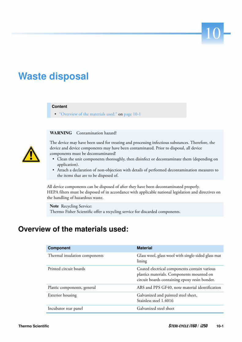
10
Waste disposal
All device components can be disposed of after they have been decontaminated properly.HEPA filters must be disposed of in accordance with applicable national legislation and directives on the handling of hazardous waste.
Overview of the materials used:
Content
• “Overview of the materials used:“ on page 10-1
WARNING Contamination hazard!
The device may have been used for treating and processing infectious substances. Therefore, the device and device components may have been contaminated. Prior to disposal, all device components must be decontaminated!• Clean the unit components thoroughly, then disinfect or decontaminate them (depending on application).
• Attach a declaration of non-objection with details of performed decontamination measures to the items that are to be disposed of.
Note Recycling Service:Thermo Fisher Scientific offer a recycling service for discarded components.
Component Material
Thermal insulation components Glass wool, glass wool with single-sided glass mat lining
Printed circuit boards Coated electrical components contain various plastics materials. Components mounted on circuit boards containing epoxy resin bonder.
Plastic components, general ABS and PPS GF40, note material identification
Exterior housing Galvanized and painted steel sheet,Stainless steel 1.4016
Incubator rear panel Galvanized steel sheet
Thermo Scientific STERI-CYCLE i160 / i250 10-1

10 Waste disposalOverview of the materials used:
Outer door Galvanized and painted steel sheet,Stainless steel 1.4016
Door inner panel 1.4301 stainless steel sheeting
Control panel and display window protective foil Polyethylene
Heater Silicone-sheathed resistance heater wires
Workspace containers, installed components and shelves
Stainless steel 1.4301, Copper
Insert for pressure compensation opening Stainless steel 1.4301 (base), 1.4404 (sinter filter)
Glass screen Sodium silicate glass
Sensor block (TCD) Stainless steel 1.4301
Cables Plastics- and silicon-sheathed copper stranded wire
Elastomers, general Silicone
Filter HEPA-filter, micro-fine glass,Gas filter with polypropylene casing and GF/PTFE membrane,Pre-filter, stainless steel 1.4401 wire mesh
Packaging Corrugated cardboard, polyethylene foil, styrofoam shaped elements and polypropylene
Door seal magnet Permanent magnet
Component Material
10-2 STERI-CYCLE i160 / i250 Thermo Scientific

11
Specifications
Content
• “STERI-CYCLE i160“ on page 11-2
• “STERI-CYCLE i250“ on page 11-6
Thermo Scientific STERI-CYCLE i160 / i250 11-1

11 SpecificationsSTERI-CYCLE i160
STERI-CYCLE i160
Name Unit Value
Mechanical
Outer dimensions (W x H x D) mm 637 x 905 x 790(25.08 x 35.63 x 31.10 inch)
Inner dimensions (W x H x D) mm 470 x 607 x 576(18.50 x 23.90 x 22.68 inch)
Inner space volume,of which useable volume
ll
approx. 165approx. 100
Inserts (B x T)Quantity of components deliveredQuantity, maximumSurface loading capacity, maximum
mmpcs.pcs.kg
423 x 465 (16.65 x 18.31 inch)31110 per insert
Overall device loading capacity, maximum kg 30
Weight kg 83
Weight, without accessories kg 78.4
Thermal
Thermal safety features to DIN 12880:2007-05 Class 3.1 (Overtemperature controller, providing alarming function upon excessive temperature condition)
Ambient temperature range °C +18...34
Ambient temperature for stacked devices °C +18...28
Temperature control range, incubation operation °C RT + 3...55
Temperature deviation from set value, over time (DIN 12880, part 2) at 37 °C
°C ± 0.1
Temperature deviation from set value, spatial (DIN 12880, part 2) at 37 °C *1)
°C <= ± 0.3
Duration of the auto-start routine: to 37 °CAmbient temperature 20 °C
h 5...10
Heat transfer to environment:at 37 °Cduring steri-run decontamination
kWh/hkWh/h
0.060.59
Humidity
Water qualities Electrical resistance:50 kOhmcm to 1 MOhmcmConductivity: 1 to 20 µS/cm
Capacities:Incubation operation
l max. 3 / min 0.5
11-2 STERI-CYCLE i160 / i250 Thermo Scientific

11 Specifications
STERI-CYCLE i160
*1) determined on the basis of DIN 12880 for devices with standard feature set. See calibration instructions for detailed information
Constant humidity at 37 °C (high humidity mode)Constant humidity at 37 °C (low humidity mode)
%rH%rH
approx. 93approx. 90
Others
Sound pressure level (DIN 45 635, part 1) dB(A) < 50
Relative ambient humidity %rH max. 80
Altitude of site m above sea level
max. 2000
Name Unit Value
Thermo Scientific STERI-CYCLE i160 / i250 11-3

11 SpecificationsSTERI-CYCLE i160
STERI-CYCLE i160
Name Unit Value
CO2 gas supply system
Gas purity % min. 99.5 or med. quality
Primary pressure bar min. 0.8 - max. 1 (11.6-14.5 psi)
Measurement and control range Vol -% 0...20
Control deviation over time Vol -% ± 0.1
CO2 measuring cell
Accuracy at 37 °C and 5% CO2 %CO2 ± 0.3
O2 gas supply system
Gas purity % min. 99.5 or med. quality
Primary pressure bar min. 0.8 - max. 1 (11.6-14.5 psi)
Measurement and control range Vol -% 1... 21 or 5...90
Control deviation over time Vol -% ± 0.2
O2 measuring cell
Accuracy at 37 °C and 21% O2 %O2 ± 0.5 (option: 1.....21% O2)± 2,0 (option: 5.....90% O2)
Electrical
Rated voltage V 1/N/PE 230 V, AC (± 10%)1/N/PE 220 V, AC (± 10%)1/N/PE 120 V, AC (± 10%)1/N/PE 100 V, AC (± 10%)
Rated frequency Hz 50/60
Degree of protection (IEC 60529) IP 20
Protection class I
Overvoltage category (EN 61010) II
Pollution degree (EN 61010) 2
Rated current A 230 V:
Decontamination: 4.6 Incubation: 2.4220 V:
Decontamination: 4.4 Incubation: 2.3120 V:
Decontamination: 8.3; Incubation: 4.6100 V:
Decontamination: 7.2; Incubation: 3.9
Circuit breaker 16 A
11-4 STERI-CYCLE i160 / i250 Thermo Scientific

11 Specifications
STERI-CYCLE i160
Rated power kW 230 V: Decontamination: 1.06 Incubation: 0.56220 V:
Decontamination: 0.97Incubation: 0.51120 V:
Decontamination: 1.01Incubation: 0.55100 V:
Decontamination: 0.72Incubation: 0.39
EMV class B
Name Unit Value
Thermo Scientific STERI-CYCLE i160 / i250 11-5

11 SpecificationsSTERI-CYCLE i250
STERI-CYCLE i250
Name Unit Value
Mechanical
Outer dimensions (W x H x D) mm 780 x 970 x 945(30.71 x 38.19 x 37.20 inch)
Inner dimensions (W x H x D) mm 607 x 670 x 629(23.90 x 26.38 x 24.76 inch)
Inner space volume,of which useable volume
l approx. 255approx. 162
Inserts (B x T)Quantity of components deliveredQuantity, maximumSurface loading capacity, maximum
mmpcs.pcs.kg
560 x 500 (22.05 x 19.68 inch)31210 per insert
Overall device loading capacity, maximum kg 30
Weight, without accessories kg 97.5
Thermal
Thermal safety features to DIN 12880:2007-05 Class 3.1(Overtemperature controller, providing alarming function upon excessive temperature condition)
Ambient temperature range °C +18...34
Ambient temperature for stacked devices °C +18...28
Temperature control range °C RT + 3...55
Temperature deviation from set value, over time (DIN 12880, part 2)
°C ± 0.1
Temperature deviation from set value, spatial (DIN 12880, part 2) at 37 °C *1)
°C ± 0.3
Duration of the auto-start routine: to 37 °CAmbient temperature 20 °C
h 5...10
Heat transfer to environment:at 37 °Cduring steri-run decontamination
kWh/hkWh/h
0.070.75
Humidity
Water qualities Electrical resistance:50 kOhmcm to 1 MOhmcm Conductivity: 1 to 20 µS/cm
Capacities:Incubation operation
l max. 3 / min 0.5
Constant humidity at 37 °C (high humidity mode)Constant humidity at 37 °C (low humidity mode)
%rH%rH
approx. 93approx. 90
11-6 STERI-CYCLE i160 / i250 Thermo Scientific
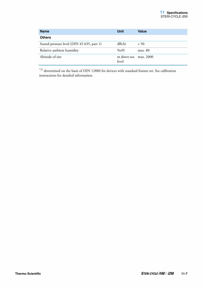
11 Specifications
STERI-CYCLE i250
*1) determined on the basis of DIN 12880 for devices with standard feature set. See calibration instructions for detailed information.
Others
Sound pressure level (DIN 45 635, part 1) dB(A) < 50
Relative ambient humidity %rH max. 80
Altitude of site m above sea level
max. 2000
Name Unit Value
Thermo Scientific STERI-CYCLE i160 / i250 11-7

11 SpecificationsSTERI-CYCLE i250
STERI-CYCLE i250
Name Unit Value
CO2 gas supply system
Gas purity % min. 99.5 or med. quality
Primary pressure bar min. 0.8 - max. 1 (11.6-14.5 psi)
Measurement and control range Vol -% 0...20
Control deviation over time Vol -% ± 0.1
CO2 measuring cell
Accuracy at 37 °C and 5% CO2 %CO2 ± 0.3
O2 gas supply system
Gas purity % min. 99.5 or med. quality
Primary pressure bar min. 0.8 - max. 1 (11.6-14.5 psi)
Measurement and control range VoI -% 1... 21 or 5...90
Control deviation over time VoI -% ± 0.2
O2 measuring cell
Accuracy at 37 °C and 21% O2 %O2 ± 0.5 (option: 1.....21% O2)± 2.0 (option: 5.....90% O2)
Electrical
Rated voltage V 1/N/PE 230 V, AC (± 10%)1/N/PE 220 V, AC (± 10%)1/N/PE 120 V, AC (± 10%)1/N/PE 100 V, AC (± 10%)
Rated frequency Hz 50/60
Degree of protection (IEC 60529) IP 20
Protection class I
Overvoltage category (EN 61010) II
Pollution degree (EN 61010) 2
Rated current A 230 V:
Decontamination: 5.5Incubation: 3.3220 V:
Decontamination: 5.3Incubation: 3.2120 V:
Decontamination: 10.4Incubation: 6.3100 V:
Decontamination: 8.9Incubation: 5.3
Circuit breaker 16 A
11-8 STERI-CYCLE i160 / i250 Thermo Scientific

11 Specifications
STERI-CYCLE i250
Rated power kW 230 V:
Decontamination: 1.26Incubation: 0.76220 V:
Decontamination: 1.16Incubation: 0.69120 V:
Decontamination: 1.25Incubation: 0.75100 V: Decontamination: 0.89 Incubation: 0.53
EMV class B
Name Unit Value
Thermo Scientific STERI-CYCLE i160 / i250 11-9

11 SpecificationsSTERI-CYCLE i250
11-10 STERI-CYCLE i160 / i250 Thermo Scientific

12
Annex: Data communication
USB interface
The units come equipped with a USB interface. The USB interface complies with Standard USB 1.1 / USB 2.0 / USB 3.0 (full speed). The USB port is operated as a virtual COM port. Therefore, the port transmission speed can be changed within the defined baud rates (9,600, 19,200, 38,400, 57,600 baud. Data exchange is accomplished via a defined command sequence structure (frames). The command sequences correspond with the RS 232 interface installation diagram.
Content
• “Structure of the command sequences for data communication“ on page 12-4
• “Overview of general parameters (addresses 0xxx)“ on page 12-5
• “Overview of incubator parameters (addresses 2xxx)“ on page 12-5
• “Error memory structure“ on page 12-8
• “Data logger structure“ on page 12-11
• “Examples of data logger codes“ on page 12-15
• “Program STERI-CYCLE i160 / STERI-CYCLE i250“ on page 12-21
Note Installing the USB port with the virtual COM port:
If the USB port is to be used for data exchange between PC and incubator, the USB port is installed as virtual COM port (USB serial port) using the supplied driver.The assigned COM port can be located in the Windows Device Manager/Ports dialog box, e.g. USB Serial Port (COM5), and is then defined as communication port in the STERI-CYCLE i160 / STERI-CYCLE i250 (see “Program STERI-CYCLE i160 / STERI-CYCLE i250“ on page 12-21).
Thermo Scientific STERI-CYCLE i160 / i250 12-1

12 Annex: Data communication
The driver can be run under the following operating systems:WIN 7, WIN 8, WIN 2000, WIN XP, WIN VISTA.
Installing the USB port driver
Plug the USB cable into the USB interface port (option) in the control box of the STERI-CYCLE i160 / STERI-CYCLE i250 and connect with a PC.As soon as the Windows Hardware Detector has identified the USB port, the Find New Hardware Wizard dialog box opens.
1. Choose the INSTALL FROM A LIST OR SPECIFIC LOCATION (ADVANCED) option.
12-2 STERI-CYCLE i160 / i250 Thermo Scientific

12 Annex: Data communication
2. Select the Install from a list or specific location (Advanced) option.
3. Select the data CD as source.
4. On the data CD, select the DRIVER sub-directory.
5. The installation routine installs the driver: EVAL22 Board USB. After the installation has been completed successfully, the routine is completed with FINISH.
Thermo Scientific STERI-CYCLE i160 / i250 12-3

12 Annex: Data communicationStructure of the command sequences for data communication
The interface transmission speed can be selected within the defined baud rates (9,600, 19,200, 38,400, 57,600 Baud) at the touchscreen of the STERI-CYCLE i160 / STERI-CYCLE i250 (see “Settings / Setup“ on page 6-17).
Structure of the command sequences for data communication
All characters sent and received in the data exchange between a PC and the incubator STERI-CYCLE i160 / STERI-CYCLE i250 are ASCII characters that can be displayed on a conventional terminal.This ensures that communication can be set up, controlled, and programmed easily.
Description of protocol
Character coding ASCII characters, capital letters are not allowed.
Reading parameters:Query: ?:aaaa:bb::cc<CR>or: ?:aaaa:bb:XXXX:cc<CR>Response: !:aaaa:bb:XXXXX:cc<CR>where: aaaa = parameter adress
bb =amount of payload in this telegram (00 – ff )cc = checksum: Inverted XOR of all bytes without checksum and <CR>XXXX = bb-bytes user data
Description of the response elements:aaaa parameter addressbb amount of payload in this telegram (00 – ff )cc Checksum: Inverted XOR of all bytes without
checksum and <CR>
Example of a software version query (50111927):Query: ?:0001:00::cc<CR>Response: !:0001:08:50111927:cc<CR>
Writing parameters:Command: !:aaaa:bb:XXXXX:cc<CR>Response: !:aaaa:bb::cc<CR>where: aaaa = parameter adress
bb =amount of payload in this telegram (00 – ff )cc = checksum: Inverted XOR of all bytes without checksum and <CR>XXXX = bb-bytes user data
Response with an error message:Response: !:aaaa:bb:XX:cc<CR>
12-4 STERI-CYCLE i160 / i250 Thermo Scientific

12 Annex: Data communication
Overview of general parameters (addresses 0xxx)
Description of the response elements:aaaa parameter address,bb amount of payload (always 02)cc Checksum: Inverted XOR of all bytes without
checksum and <CR>XX = 2 bytes error message (see table below)
Example of an unknown command:Query: ?:0005:00::cc<CR>Response !:0005:02:?1:cc<CR>
Significance of the two bytes in the error message:
Overview of general parameters (addresses 0xxx)
General parameters are system values such as date, time, and motherboard version number.
Reading general parameters
Overview of incubator parameters (addresses 2xxx)
Incubator parameters are divided into:• the basic parameters of the three control loops temperature, CO2 and O2,• the internal function parameters of operating functions and data logging.
Failure message Description
?0 Error in telegram structure or check sum
?1 Unknown error or unknown parameter
?2 Internal memory error
?3 Data error (value not within set limits)
Address Description Remarks
0001 Mainboard version number 8 places
0010 Date and time display [hours:minutes:seconds];[day:month:year]
17 bytes / decimal valuewith the format xx:xx:xx;xx:xx:xx
0011 Date[day:month:year]
8 bytes / decimal valuewith the format xx:xx:xx
0012 Time[hours:minutes:seconds]
8 bytes / decimal valuewith the format xx:xx:xx
Thermo Scientific STERI-CYCLE i160 / i250 12-5

12 Annex: Data communicationOverview of incubator parameters (addresses 2xxx)
Reading basic parameters
*1) Example of unit status and (error) status control loops(for details see error messages)
*2) All values have two decimal places.
Address Description Remarks
2000 Device status*1) (Error-) Status of the control loopstemperature,CO2, O2, rH, ref. temp.
33 bytes / hexadecimal valuewith the formatxxxxxxxx;xxxx; ...;xxxx;xxxx;xxxx
2010 Specified, actual and reference temperature*2)
23 bytes / decimal valuewith the format +xxx.xx;+xxx.xx;+xxx.xx
2020 Specified and actual CO2 content*2)
15 bytes / decimal valuewith the format +xxx.xx;+xxx.xx
2030 Specified and actual O2 content*2) 15 bytes / decimal value
with the format +xxx.xx;+xxx.xx
204a Actual water level (100% or 0%) 7 bytes / decimal valuewith the format +xxx.xx
204b Low humidity indicator (1 active, 0 inactive)
2 bytes / hexadecimalwith the format xx
12-6 STERI-CYCLE i160 / i250 Thermo Scientific

12 Annex: Data communication
Overview of incubator parameters (addresses 2xxx)
Reading internal function parameters
*1) See table with notes on disinfection and autostart run status.*2) Two bytes each per level.*3) Cylinder A active (0x01), cylinder B active (0x02), pressure in cylinder A OK (0x10), pressure in cylinder B OK (0x20).*4) For other Informations on the Error Log, see Chapter 13.5.*5) Place the reading pointer on the first entry, read up to 7 entries max.*6) Send the next 7 entries. Set reading pointer automatically to next new entry, read up to 7 entries max.*7) Re-send entries of last telegram. Can be used after communication error has occurred.
Address Description Remarks
2100 Status of run *1) andRemaining run time [hours:minutes]Disinfection, date and time of last start
25 bytes / decimal valuewith the formatxx;+xxx:xx;xx.xx.xx;xx:xx
2105 Status of run *1), current CO2 offset + waiting period [minutes:seconds]auto-start, Date and time of last start
25 bytes / decimal valuewith the format xx;xx.x;+xxx:xx;xx.xx.xx;xx:xx
2140 Status of as cylinder changeover switch Read CO2
*3)
2 bytes / hexadecimalwith the format xx
2141 Status of as cylinder changeover switch Read O2
*3)
2 bytes / hexadecimalwith the format xx
2300 Read the Error Log (current errors) *4)
Up to 241 bytes / hexadecimal valueFormat, see section on this topic
2301 Read the Error Log(older errors) *4)
Up to 241 bytes / hexadecimal valueFormat, see section on this topic
2400 Query (Start) of data stored in the data logger *5)
Up to 224 bytes / hexadecimal valueFormat, see section on this topic
2401 Query of other data stored in the data logger *6)
224 bytes / hexadecimal valueFormat, see section on this topic
2402 (Repeat) query for last data logger query *7)
224 bytes / hexadecimal valueFormat, see section on this topic
2410 Read out writing cycle of the data logger in hours/minutes/seconds
8 bytes / decimal value with the format xx:xx:xx
Thermo Scientific STERI-CYCLE i160 / i250 12-7

12 Annex: Data communicationError memory structure
Note on *3) disinfection and auto-start run status:
Error memory structure
The error memory contains 22 error messages. A query is responded with 22 data sets with a colon as separator and can be queried using the following commands:
Query: ?:2300:00::cc<CR>Reading the first 11 error memory entries.
Query: ?:2301:00::cc<CR>Reading the first 11 error memory entries.
These data sets consist of 11 byte and are encrypted in 21 ASCII characters prior to data transmission. Example: The byte 0x23 is converted into the ASCII characters 0x32 (“2”) and 0x33 (“3”).• Byte 1 consists of 1 characters,• Bytes 2 - 11 consist of 2 characters.
Therefore, a response consists of 1+(10 x 2) = 21 data bytes plus separator.A data set always delivers the date, the time, the faulty control loop, the device status, and the error message.
Bit Disinfection auto-start
0x00 Steri-run not activated auto-start not activated
0x01 Initialization Initialization
0x02 Wait until open door time expires Wait until open door time expires
0x03 Wait until door closes Wait until door closes
0x04 Start Start
0x05 Heating Heating
0x06 Holding Perform reverse voltage adjustment
0x07 Condensation Waiting period 1
0x08 Cooling Set tolerance range
0x09 Drying Build up stable moisture
0x0A Wait for enable Perform reverse voltage adjustment
0x0B Cancellation Waiting period 2
0x0C - Determine offset
0x0D - Read out, check offset
0x0E - Release
0x0F - Cancellation
12-8 STERI-CYCLE i160 / i250 Thermo Scientific

12 Annex: Data communication
Error memory structure
Example of a response:
!:2300:fb:10b01060f372280000002:20b01060f38100001... ...:80
First data set: !:2300:fb:10b01060f372280000002: (with 21 bytes)
Second data set: 20b01060f38100001... ...:80beginning of the second data set after 01060 bytes of the first data set and of the separator [1 byte])
Error memory data set structure scheme:
Therefore, the following information is transmitted in this data set:• Created on 1 January 2006 at 15:55:34 hrs.• A device error has occurred and the set temperature is too high.
00 0b 01 06 0f 37 22 8000 0002
Typ fehlerhafter Regelkreis
0x00 = Fehler im
Regelkreis Temperatur 00
Datum / Tag
0x0b = der 11. des Monats 0b
Datum / Monat
0x01 = Januar 01
Datum / Jahr
0x06 = 2006 06
Uhrzeit / Stunden
0x0f = 15 Uhr 0f
Uhrzeit / Minuten
0x37 = 55 Minuten 37
Uhrzeit / Sekunden
0x22 = 34 Sekunden 22
Gerätestatus
0x8000 = Gerätefehler vor-
handen 8000
Fehlermeldung
0x0002 = Istwert über 0002
Type of erroneous control loop
0x00 = Error in control
loop temperature
Date / Day
0x0b = 11th of months
Date / Month
0x01 = January
Date / Year
0x06 = 2006
Time / Hours
0x0f = 15 o’clock
Time / Minutes
0x37 = 55 minutes
Time / Seconds
0x22 = 34 seconds
Error message
0x0002 = Actual value high
Device status
0x8000 = Device error
present
Thermo Scientific STERI-CYCLE i160 / i250 12-9

12 Annex: Data communicationError memory structure
Overview of the possible error messages in hex coding
Overview of the possible error messages in bit codingGeneral device status, temperature and CO2 control loop:
Hex Code Description / Type
0x00 Temperature control loop
0x01 CO2 control loop
0x02 O2 control loop
0x07 Water level
0x08 General device status
Bit General device status
0x0002 Device door open too long
0x0004 Display not communicating
0x0008 Implausible mainboard parameter (EEPROM defective)
0x0010 Data logger defective (unit can continue to function)
0x0020 Error for disinfection / steri-run
0x0040 Power-down during steri-run
0x0080 Error auto-start
0x0100 ADC-test failed
0x0400 Fan error
0x1000 IR sensor system replaced (info)
0x2000 auto-start active (info)
0x4000 Disinfection active (info)
0x8000 Device error has occurred (info)
Bit Error status of temperature control circuit
0x0001 Sensor breakage
0x0002 Actual value high
0x0004 Actual value low
0x0008 Actual value not plausible
0x0010 Calibration values too high/low
Bit CO2 control loop error status
0x0001 Sensor breakage
0x0002 Actual value high
12-10 STERI-CYCLE i160 / i250 Thermo Scientific

12 Annex: Data communication
Data logger structure
O2 control loop and water level:
Data logger structure
The data logger can store up to 10,000 events. Depending on the setting for the logging cycle (in sections of seconds), e.g. for a value of 10,000 s (default value), the events of about 5 days can be stored.The data logger stores the following information:• important user actions, system events, and error messages,• measured data of the three control loops during incubation operation.
The data logger can be queried using the following commands:Query: ?:2400:00::cc<CR>
Set the data logger pointer to the oldest entry and output thefirst data sets.
Query: ?:2401:00::cc<CR>Output of the following data sets, the reading pointer automatically moves gradually from the older entries to the current entries.
Query: ?:2402:00::cc<CR>
0x0004 Actual value low
0x0010 Calibration values too high/low
0x0020 Error communication (to sensor)
0x0040 Error communication (to gas cylinder changing unit)
0x0080 No gas available, bottle A and B empty
0x0200 Cylinder A empty
0x0400 Cylinder B empty
Bit CO2 control loop error status
Bit O2 control loop error status
0x0001 Sensor breakage
0x0002 Actual value high
0x0004 Actual value low
0x0020 Error communication (to sensor)
0x0040 Gas cylinder changeover switch does not communicate
0x0080 No gas available, bottle A and B empty
0x0200 Cylinder A empty
0x0400 Cylinder B empty
Bit Water level error status
0x0001 No water
Thermo Scientific STERI-CYCLE i160 / i250 12-11

12 Annex: Data communicationData logger structure
Repeated output of the most recently read data, this commanddoes not move the reading pointer. This command can be used to avoid data loss
after a communication error has occurred
Each query command is responded with up to 7 data sets that follow one another without a separator. These data sets consist of 16 bytes and are encrypted into 32 ASCII characters prior to transmission.For example, the byte 0x23 is converted into the ASCII characters:0x32 (“2“) and 0x33 (“3“).Therefore, a response consists of up to 7 X 16 = 112 bytes, i.e. 224 ASCII characters.The date and time (without seconds), the device status and the type of data logger entry are always transmitted in a data set (byte 0-7, and ASCII characters 0-15). Also, depending on the entry, the current actual values or set values of the control loops or other parameters can be entered (byte 8-15 or ASCII character 16-31).
Example of a response:!:2400:e0:010b01060f3700000177002800d40000110b01060f3800000172003200d20352... ...:80
First data set !:2400:e0:010b01060f3700000177002800d4000011(consisting of 32 byte ASCII characters)
Second data set 0b01060f3800000172003200d20352... ...:80(beginning of the second data set after 32 bytes of the first data set)
12-12 STERI-CYCLE i160 / i250 Thermo Scientific

12 Annex: Data communication
Data logger structure
Data logger data set structure scheme:
Therefore, the following information is transmitted in this data set:• Created on 1 January 2006 at 15:55 hrs.• The device status reports no particularities,• the temperature is 37.5°C,• gas concentration 4.0% CO2, 21.2% O2.
01 0b 01 06 0f 37 0000 0177 0028 00d4 0000
01
0b
01
06
0f
37
0000
0177
20028
00d4
0000
Type of data logger entry
0x01 = Standard entry
which is saved every 60 s
Date / Day
0x0b = 11th of months
Date / Months
0x01 = January
Date / Year
0x06 = 2006
Time / Hours
0x0f = 15 o’clock
Time / Minutes
0x37 = 55 minutes
Device status
0x0000 = everything ok
Based on type, here, the current
temperature in 1/10 °Celsius
0x0177 = 37.5 °C
Based on type, here, the current
CO concentration in 1/10 %
0x0028 = 4.0 % CO2
2
Based on type, here, the current
O concentration in 1/10 %
0x00d4 = 21.2 % O2
Reserved for rH in 1/10 %
always
0x0000 = 0 %
Note Example of a code:For an example of a code, please refer to the end of this chapter.
Thermo Scientific STERI-CYCLE i160 / i250 12-13

12 Annex: Data communicationData logger structure
Overview of possible event entries in bit codingOverview of event entries, Part I:
Code Event Special information (Byte 8-15)
0x01 Set values from all servo control circuits (periodically in one-minute cycles)
Current values for temperature, CO2, O2 and rH
0x02 Set value change (at beginning of new section)
Set value for temperature, CO2, O2 and rH
0x10 Set value change T Set value for temperature, CO2, O2 and rH
0x11 Set value change CO2 Set value for temperature, CO2, O2 and rH
0x12 Set value change O2 Set value for temperature, CO2, O2 and rH
0x20 New error T Status / error registration for temperature, CO2, O2 and rH
0x21 New error CO2 Status / error registration for temperature, CO2, O2 and rH
0x22 New error O2 Status / error registration for temperature, CO2, O2 and rH
0x2F New error system Status / error registration for temperature, CO2, O2 and rH
0x30 Power reset Set value for temperature, CO2, O2 and rH
0x31 Door open Current actual values for temperature, CO2, O2 and rH
0x32 Door closed Current actual values for temperature, CO2, O2 and rH
0x40 Calibration T Calibration level (2 bytes), old temperature, new temperature (2 bytes each)
0x41 Calibration CO2 Calibration level (2 bytes), old CO2 value, new CO2 value (2 bytes each (2 bytes each)
0x42 Calibration O2 Calibration level (2 bytes), old O2 value, new O2 value (2 bytes each)
0x50 Start auto-start Status / error registration for temperature, CO2, O2 and rH
0x51 auto-start successfully completed Current actual values for temperature, CO2, O2 and rH
12-14 STERI-CYCLE i160 / i250 Thermo Scientific

12 Annex: Data communication
Examples of data logger codes
Overview of event entries, Part II:
Examples of data logger codes
An entry in the data logger is 16 bytes large and has the following structure:
1st byte: indicates the event (e.g. door open 1x31, measured value entry 0x01)2nd byte: day of entry 3rd byte: month4th byte: year5th byte: hours6th byte: minutes7th and 8th byte: device status9th to 16th byte: various data on the event
Code Event Special information (Byte 8-15)
0x52 auto-start completed with error Status / error registration for temperature, CO2, O2 and rH
0x53 auto-start stopped manually Status / error registration for temperature, CO2, O2 and rH
0x60 Start steri-run Status / error registration for temperature, CO2, O2 and rH
0x61 steri-run successfully completed Current actual values for temperature, CO2, O2 and rH
0x62 steri-run completed with error Status / error registration for temperature, CO2, O2 and rH
0x63 steri-run stopped manually Status / error registration for temperature, CO2, O2 and rH
0x70 Gas mon. cylinder A empty Gas monitoring status (2 bytes), 4 bytes empty
0x71 Gas mon. cylinder B empty Gas monitoring status (2 bytes), 4 bytes empty
0x72 Gas mon. changeover Gas monitoring status (2 bytes), 4 bytes empty
0x90 Start low humidity Current actual values for temperature, CO2, O2 and rH
0x91 Stop low humidity Current actual values for temperature, CO2, O2 and rH
0xe0 Delete data logger Current actual values for temperature, CO2, O2 and rH
0xff Last entry of data logger No information, not even on date, time, and status
Thermo Scientific STERI-CYCLE i160 / i250 12-15

12 Annex: Data communicationExamples of data logger codes
Functions for data logger queries
The following code example for reading the data logger uses six functions:• ahex// converts the received ASCII character into a hexadecimal number,
• send_telegramm// sends a query to the data logger,
• get_telegramm// receives a response data the data logger,
• time_2_str// uses a hexadecimal value to create ASCII characters in time format,
• num_2_string// uses hexadecimal values to create ASCII characters to be entered into a file,
• read_datalogger// edits the received data and writes them into a file.
Example of a code for a a data logger query
char ahex (char a)
char ahex(char a){char i;char hexa[16]=“0123456789abcdef“;
for (i = 0; i < 16; i++)if (a == hexa[i])return (i);
return 0;}
send_telegramm
void send_telegramm(char *p){char string [15];unsigned char bcc = 0xFF;char i;
// copy telegram togetherstrncpy (&string[0], „?:xxxx:00::00\r“, 14);
// insert 4-digit addressstrncpy (&string[2], p, 4);
// calculate checksum: inverted XOR of all bytes// without checksum and <CR>
for (i = 0; i < 11; i ++)bcc = (bcc^string[i]);
// copy checksumstring[11] = hexa(bcc/16);string[12] = hexa(bcc%16);
12-16 STERI-CYCLE i160 / i250 Thermo Scientific

12 Annex: Data communication
Examples of data logger codes
// send telegramComWrt (COM_NR, string, 14);return;}
get_telegramm
int get_telegramm(char *p){int reading_count = 0;
// reading the telegram character by characterdo
ComRd(COM_NR, &p[reading_count], 1);// until reception of <CR>
while ((p[reading_count++] != ‘\r’));// return = number of received characters
return (reading_count);}
time_2_str
char time_2_str (int z, char * b){
char i;// output two numerals
for (i = 1; i >= 0; i--){//calculate value
b[i] = z%10+0x30;// reduce default value
z = z/10;}return (2);}
num_2_string
char num_2_str (int z, char * b){
// number with one decimal placechar a[12];char i, l;int rest = 0;l = 0;
// Negative number? if (z < 0) {
// set algebraic signb[0] = ‘-’;l = 1;
// convert valuez = 0xffffffff-z+1;
}// store decimal place
Thermo Scientific STERI-CYCLE i160 / i250 12-17

12 Annex: Data communicationExamples of data logger codes
rest = z % 10;// cut off decimal place
z = z / 10;// calculate and copy number before decimal separator
for (i = 0; i < 12; i++){// calculate value
a[i] = z%10+0x30;// reduce default value
z = z/10;// Number copied completely?
if (z == 0) break;}for ( ; i >= 0; i--)b[l++] = a[i];
// calculate and copy number after decimal separatorb[l++] = ‘,’;
// calculate valueb[l++] = rest%10+0x30;return (l);}
read_datalogger
int read_datalogger (){#define SIZE_DATA2 16#define EVENT_STATUS 0x01unsigned char buffer[300], string [300];unsigned char zahlenstring [150], datestring, timestring;unsigned char excelstring [150];unsigned char len, h,i;unsigned int read_count,status;#define EVENT_DATA.END 0xFFchar data;int GetTele = 0GetError = 0,// writing the title line in the fileWriteFile (FileHandle, „Date;Time;Comment;Temp Act.;CO2 Act.;O2 Act.;rH Act.;Temp Set;CO2 Set;O2 Set;rH Set;\n“, 85);// infinite loopwhile (1)
{// set data logger to beginning and read
if (!GetTele) {send_telegramm („2400“);}else{
// read additional data setssend_telegramm („2401“);}len = get_telegramm (buffer);
// no telegram received
12-18 STERI-CYCLE i160 / i250 Thermo Scientific

12 Annex: Data communication
Examples of data logger codes
if (!len) {GetError ++;
// requerysend_telegramm („2402“);len = get_telegramm (buffer);
// again, no telegram receivedif (!len) return 1;}
// increase telegram counterGetTele ++;
// length of sent payloadlen = (ahex(buffer[7]) * 0x10 + ahex(buffer[8])) / 2;
// converting ASCII string into usable numeric stringfor (i = 0; i < (string); i++)numeric string [i] = (ahex(buffer[10 + (2*i)]) * 0x10 + ahex(buffer[11 + (2*i)]));
// calculation of the sent data packagesdata = ((len) / SIZE_DATA2);
// evaluation of all data packagesfor (i = 0; i < data; i++)9{len = 0;
// write time and date into filelen += time_2_str (numeric string[1+i*SIZE_DATA2], &excelstring[len]);excelstring[len ++] = ‘.’;len += time_2_str (numeric string[2+i*SIZE_DATA2], &excelstring[len]);excelstring[len ++] = ‘.’;len += time_2_str (numeric string[3+i*SIZE_DATA2], &excelstring[len]);excelstring[len ++] = ‘;’;len += time_2_str (numeric string[4+i*SIZE_DATA2], &excelstring[len]);excelstring[len ++] = ‘:’;len += time_2_str (numeric string[5+i*SIZE_DATA2], &excelstring[len]);excelstring[len ++] = ‘:’;len += time_2_str (0, &excelstring[len]);excelstring[len ++] = ‘;’;
switch (numeric string[i*SIZE_DATA2]){case EVENT_STATUS:
//check cyclic entries for device errorsstatus = numeric string[6+i*SIZE_DATA2]*0x100+numeric string[7+i*SIZE_DATA2];
if (status & INFO_ERROR){str_cpy (&excelstring[len], „Error active;“, 13); len += 13;
}else{
// query all device errors (see “Overview of possible event entries in bit coding Overview of event
Thermo Scientific STERI-CYCLE i160 / i250 12-19

12 Annex: Data communicationExamples of data logger codes
entries, Part I:“ on page 12-14)if (status & DOOR_LONG){
str_cpy (&excelstring[len], „Door open too long;“,19);len += 19;
else {if (status & DOOR_OPEN){
str_cpy (&excelstring[len], „Door open;“, 10); len += 10;}
}// query remaining device errors now// ·// ·// ·// ·// ·//and finally query cyclic nominal values entries without device // errors//query all
else{str_cpy (&string[string], „ok;“, 3);string += 3;
}}
// copy nominal values from numeric string to excel stringlen += num_2_str ((numeric string[8+i*SIZE_DATA2]*0x100+numeric string[9+i*SIZE_DATA2]), &excelstring[len]);excelstring[len ++] = ‘;’;len += num_2_str ((numeric string[10+i*SIZE_DATA2]*0x100+numeric string[11+i*SIZE_DATA2]), &excelstring[len]);excelstring[len ++] = ‘;’;len += num_2_str ((numeric string[12+i*SIZE_DATA2]*0x100+numeric string[13+i*SIZE_DATA2]), &excelstring[len]);excelstring[len ++] = ‘;’;len += num_2_str ((numeric string[14+i*SIZE_DATA2]*0x100+numeric string[15+i*SIZE_DATA2]), &excelstring[len]);excelstring[len ++] = ‘;’;
// enter set values from herelen += num_2_str (SollTemp, &excelstring[len]);excelstring[len ++] = ‘;’;len += num_2_str (SollCO2, &excelstring[len]);excelstring[len ++] = ‘;’;len += num_2_str (SollO2, &excelstring[len]);excelstring[len ++] = ‘;’;len += num_2_str (SollrH, &excelstring[len]);excelstring[len ++] = ‘;’;excelstring[len] = ‘\n’; len += 1; WriteFile (FileHandle, excelstring, len);break;
12-20 STERI-CYCLE i160 / i250 Thermo Scientific

12 Annex: Data communication
Program STERI-CYCLE i160 / STERI-CYCLE i250
// query the remaining events from herecase EVENT_FORMAT_DATALOG:
WriteFile (FileHandle, excelstring, len); WriteFile (FileHandle, „Data logger erased;\n“,20); break;
case EVENT_POWER_ON:// update of set values
SetTemp = numeric string [8+i*SIZE_DATA2]*0x100+numeric string[9+i*SIZE_DATA2];SollCO2 = numeric string[10+i*SIZE_DATA2]*0x100+numeric string[11+i*SIZE_DATA2];SollO2 = numeric string[12+i*SIZE_DATA2]*0x100+numeric string[13+i*SIZE_DATA2];SollrH = numeric string[14+i*SIZE_DATA2]*0x100+numeric string[15+i*SIZE_DATA2];WriteFile (FileHandle, excelstring, len);WriteFile (FileHandle, „Power on;\n“, 10); break;
case..//query all events here (see “Overview of possible event entries in bit coding Overview of event entries, Part I:“ on page 12-14)// cancel 0xFF indicates the end of the data logger
case 0xFF:WriteFile (FileHandle, „End;\n“,5);}
}return 0;}
Program STERI-CYCLE i160 / STERI-CYCLE i250
The program provides a user surface (only with English menu designation) for handling the data communication between a device and a connected PC.
This program is used for:
Thermo Scientific STERI-CYCLE i160 / i250 12-21

12 Annex: Data communicationProgram STERI-CYCLE i160 / STERI-CYCLE i250
• Reading and archiving error messages (error logger). The data sets are stored in the meta format *.CSV.
• Reading and archiving event entries (data logger). The data sets are stored in the meta format *.CSV.
• Creating a service file (servicefile) to be sent to the Technical Service of Thermo Fisher Scientific. The information of the service file is very useful for systematic troubleshooting. The data sets are stored in the proprietary format *.SRF.
Installing the STERI-CYCLE i160 & STERI-CYCLE i250
1. Starting the installation routine:• On the data CD in the subdirectory PROGRAMS, double-click on the file SETUP.EXE to open this file.
2. Locate the installation directory for the program.
3. In the sequence of the given installation steps:
• confirm the licence agreement,
• confirm the extent of installation,
• after the message on the completeness of the installation has been displayed, close the installation surface and restart the computer.
12-22 STERI-CYCLE i160 / i250 Thermo Scientific
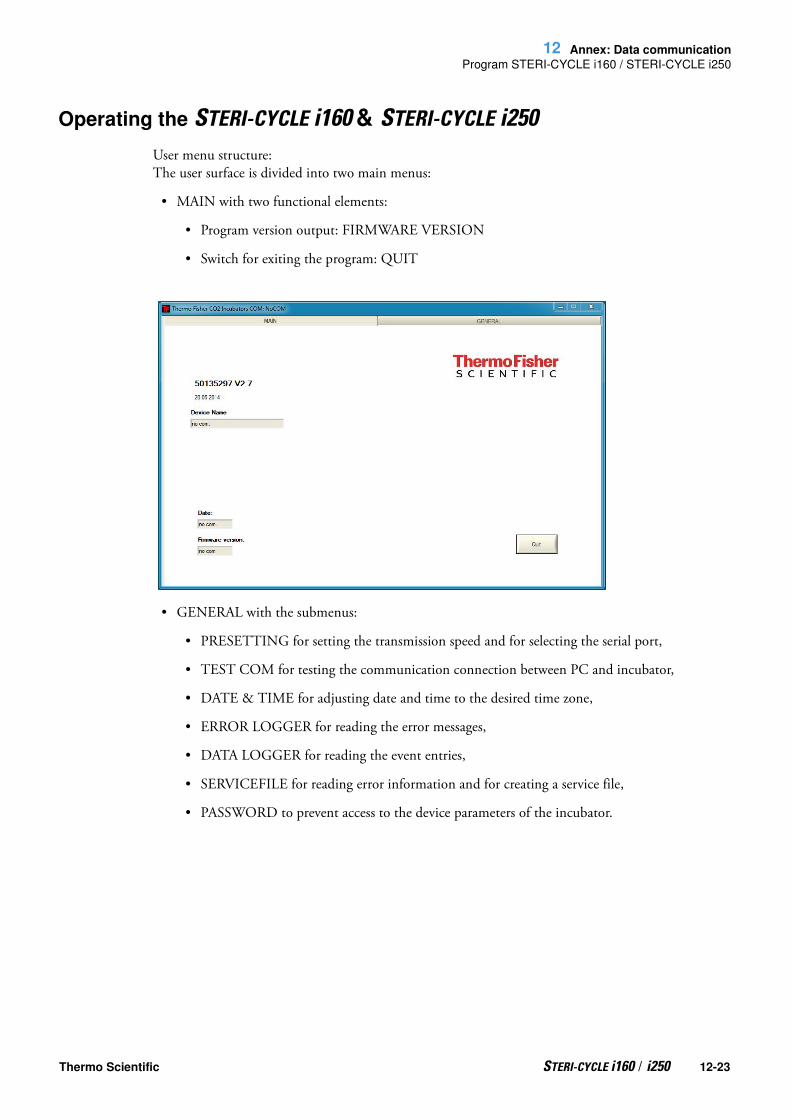
12 Annex: Data communication
Program STERI-CYCLE i160 / STERI-CYCLE i250
Operating the STERI-CYCLE i160 & STERI-CYCLE i250
User menu structure:The user surface is divided into two main menus:
• MAIN with two functional elements:
• Program version output: FIRMWARE VERSION
• Switch for exiting the program: QUIT
• GENERAL with the submenus:
• PRESETTING for setting the transmission speed and for selecting the serial port,
• TEST COM for testing the communication connection between PC and incubator,
• DATE & TIME for adjusting date and time to the desired time zone,
• ERROR LOGGER for reading the error messages,
• DATA LOGGER for reading the event entries,
• SERVICEFILE for reading error information and for creating a service file,
• PASSWORD to prevent access to the device parameters of the incubator.
Thermo Scientific STERI-CYCLE i160 / i250 12-23

12 Annex: Data communicationProgram STERI-CYCLE i160 / STERI-CYCLE i250
Function of the user menu:
PRESETTINGThe submenu PRESETTING is used to set the transmission speed and to select the serial port.
1. Select a transmission speed within the range of 9,600 to 115,200 baud.
2. Select the serial port of the PC. If the USB driver is installed, the (virtual) Com Port assigned to the USB port can be selected (see “USB interface“ on page 12-1).
3. Accept the settings:• Press the CHANGE key.
4. Save the settings (in an INI file):• Press the SAVE TO FILE key.
Note Transmission speeds:The transmission speed settings in the user menu PRESETTING and of the device must be identical!
12-24 STERI-CYCLE i160 / i250 Thermo Scientific

12 Annex: Data communication
Program STERI-CYCLE i160 / STERI-CYCLE i250
TEST COMThe submenu TEST COM is used for testing the communication connection with the settings defined in the submenu PRESETTING.
1. Example of a query for the currently measurable temperature values of the incubator:• Query: ? (default, not changeable)• Address: 2010 (Address temperature value: set value, actual value, reference value)
2. Send the query to the incubator:• Press the SEND key.• If the incubator returns a response string, the communication connection to the incubator has been established.
• If a connection cannot be established, an error dialog is displayed:
• 3. Exit the error dialog:• Press the OK key.
Thermo Scientific STERI-CYCLE i160 / i250 12-25

12 Annex: Data communicationProgram STERI-CYCLE i160 / STERI-CYCLE i250
DATE & TIMEThe submenu DATE & TIME is used for adjusting date and time to the desired time zone.
1. Data in the two text boxes must be entered in the format DD.MM.YY (day, month, year).
2. Accept the input data:• Press the SET key.
ERROR LOGGER The submenu ERROR LOGGER is used for reading the error messages into the text box of the user surface.
The data sets can be stored in the metaformat *.CSV.• Saving data sets as files:• Press the SAVE TO FILE key.
DATA LOGGERThe submenu DATA LOGGER is used for reading the event entries into the text box of the user surface.
12-26 STERI-CYCLE i160 / i250 Thermo Scientific

12 Annex: Data communication
Program STERI-CYCLE i160 / STERI-CYCLE i250
The data sets can be stored in the metaformat *.CSV.
1. Read the data sets:• Press the READ key.
2. The progress of the data transmission is indicated in the three text boxes:• AMOUNT DATA: Total number of transmitted data sets.• AMOUNT TELEGRAMS: Therein the number of transmitted event entries.• AMOUNT ERRORS: Therein the number of transmitted error messages.
SERVICEFILEThe submenu SERVICEFILE is used for reading error informations and for creating a service file from it, saved with the proprietary extension *srf. The service file is transmitted to the Technical Service of Thermo Fisher Scientific for fault analysis.
1. Create the service file :• Press the CREATE SERVICEFILE key.• Define file name and saving directory in the Windows dialog box.
2. Start saving process:• Press the OK key.
Note Duration of the data transmission:As the data logger can contain up to 10,000 data sets, the data transmission to a PC may take some time.
Note Duration of the procedure:The compilation of device informations and the creation of the service file may take some time.
Thermo Scientific STERI-CYCLE i160 / i250 12-27

12 Annex: Data communicationProgram STERI-CYCLE i160 / STERI-CYCLE i250
PASSWORDThe submenu PASSWORD can only be accessed by the service personnel of Thermo Fisher Scientific.
12-28 STERI-CYCLE i160 / i250 Thermo Scientific

13
Device log
Please list carried out works here:
Device type: Part No.:
Serial number: Service number:
Location: Operator’s note:
Work carried out: Comments: Date Signature
Thermo Scientific STERI-CYCLE i160 / i250 13-1

13 Device log
13-2 STERI-CYCLE i160 / i250 Thermo Scientific

14
Contact Information Thermo Scientific
Overview of the Thermo Fisher international sales organisations postal address Germany:
Thermo Electron LED GmbHRobert-Bosch-Straße 1D - 63505 Langenselbold
Enquiries from Germany:Phone Sales 0800 1 536376Phone Service 0800 1 112110Fax Sales/Service 0800 1 112114Email [email protected] email: [email protected]
Enquiries from Europe, Middle East and Africa:Phone + 49 (0) 6184 / 90-6940Fax + 49 (0) 6184 / 90-7474Email [email protected]
Postal address USA:Thermo Scientific275 Aiken RoadAsheville, NC 28804USA
Enquiries from North America:
Phone +1 800-879 7767 +1 800-879 7767Fax +1 828-658 0363Emai: [email protected]
Enquiries from Latin America:
Phone +1 828-658 2711Fax +1 828-645 9466Emai: [email protected]
Enquiries from Asia Pacific:Phone +852-2711 3910Fax +852-2711 3858Emai: [email protected]
Thermo Scientific STERI-CYCLE i160 / i250 14-1

14 Contact Information Thermo Scientific
Enquiries al address USA:
Thermo Scientific275 Aiken RoadAsheville, NC 28804USA
Enquiries from USA/Canada
Sales: +1 866 984 3766Service+1 800 438 4851
Enquiries from Latin AmericaSales: +1 866 984 3766Service:+1 866 984 3766
Enquiries from Asia:China
Sales: +86 10 8419 3588Service:Toll free 8008105118
Support Mobile 4006505118 or +86 10 8419 3588
IndiaSales: +91 22 6716 2200Service:Toll free 1 800 22 8374 or +91 22 6716 2200
JapanSales: +81 45 453 9220Service:+81 45 453 9224
Enquiries from the Rest of Asia/Australia/New Zealand
Sales: +852 2885 4613Service:+65 6872 9720
Enquiries from Countries not listed / Rest of EMEA
Sales: +49 6184 90 6940 or +33 2 2803 2000Service:+49 6184 90 6940
Enquiries from Europe:
AustriaSales: +43 1 801 40 0Service:+43 1 801 40 0
Belgium
Sales: +32 53 73 4241Service:+32 53 73 4241
Finland/Nordic/Baltic countries
Sales: +358 9 329 100Service:+358 9 329 100
France
Sales: +33 2 2803 2180Service:+33 825 800 119
14-2 STERI-CYCLE i160 / i250 Thermo Scientific

14 Contact Information Thermo Scientific
Germany:
Postal Address Germany:Thermo Electron LED GmbHRobert-Bosch-Straße 1D - 63505 Langenselbold
Phone
Sales Toll free 0800 1 536 376or +49 6184 90 6940
Service Toll free 0800 1 112110or +49 6184 90 6940
E-Mail [email protected]
ItalySales +39 02 95059 341Service+39 02 95059 250
Netherlands
Sales +31 76 579 5555Service+31 76 579 5639
Russia/CIS
Sales +7 812 703 4215Service+7 812 703 4215
Spain/Portugal
Sales +34 93 223 0918Service+34 93 223 0918
SwitzerlandSales +41 61 716 7755Service+41 61 716 7755
UK/IrelandService+44 870 609 9203Sales +44 870 609 9203
© 2013 Thermo Fisher Scientific Inc. All rights reserved. All trademarks are the property of Thermo Fisher Scientific Inc. and its subsidiaries. Specifications, terms and pricing are subject to change. Not all products are available in all countries. Please consult your local sales representative for details.
Thermo Scientific STERI-CYCLE i160 / i250 14-3

14 Contact Information Thermo Scientific
thermoscienti c.com
© 2013 Thermo Fisher Scientific Inc. All rights reserved. All trademarks are the property of Thermo Fisher Scientific Inc. and its subsidiaries. Specifications,
terms and pricing are subject to change. Not all products are available in all countries. Please consult your local sales representative for details.
Thermo Fisher Scientific,San Jose, CA USA is ISO Certified.
14-4 STERI-CYCLE i160 / i250 Thermo ScientificThermo Scientific GenPure Pro 103
Thermo Fisher Scienti c
81 Wyman StreetWaltham, MA 02451


![Forma Steri-Cult CO2 Incubator User Manual Rev. 19 [EN]tools.thermofisher.com/content/sfs/manuals/Steri-Cult-Model-3307-and-3310-Incubator... · ii 7023307 Steri-Cult Thermo Scientific](https://img.dokumen.tips/doc/110x75/5d51166388c993a53b8bde6a/forma-steri-cult-co2-incubator-user-manual-rev-19-entools-ii-7023307-steri-cult.jpg)