Embed Size (px)
Citation preview
Workbook TP 111
Festo Didactic
094465 en
Closed-Loop Pneumatics
TP111 � Festo Didactic
Authorised applications and liability
The Learning System for Automation has been developed and preparedexclusively for training in the field of automation. The training organiza-tion and / or trainee shall ensure that the safety precautions described inthe accompanying Technical documentation are fully observed.
Festo Didactic hereby excludes any liability for injury to trainees, to thetraining organization and / or to third parties occurring as a result of theuse or application of the station outside of a pure training situation, un-less caused by premeditation or gross negligence on the part of FestoDidactic.
Order No.: 94465Description: TEACHW. PNEUMDesignation: D.S111-C-SIBU-GBEdition: 04.2001Layout: 14.05.2001, OCKER IngenieurbüroGraphics: OCKER IngenieurbüroAuthors: J. Gerhartz, D. Scholz
© Copyright by Festo Didactic GmbH & Co., D-73770 Denkendorf 2001
The copying, distribution and utilization of this document as well as thecommunication of its contents to others without expressed authorizationis prohibited. Offenders will be held liable for the payment of damages.All rights reserved, in particular the right to carry out patent, utility modelor ornamental design registrations.
Parts of this training documentation may be duplicated, solely for train-ing purposes, by persons authorised in this sense.
TP111� Festo Didactic
3
Preface
The Learning System for Automation by Festo Didactic is formulatedaccording to various training prerequisites and vocational requirements.It has been divided into the following training packages:
� Basic packages which convey basic knowledge spanning a widerange of technologies
� Technology packages which deal with important subjects of open andclosed-loop control technology
� Function packages to explain the basic functions of automated sys-tems
� Application packages to facilitate practice-orientated vocational andfurther training.
The technology packages deal with the technologies of pneumatics,electro-pneumatics, programmable logic controllers, hydraulics, electro-hydraulics, proportional hydraulics, closed-loop pneumatics and hydrau-lics.
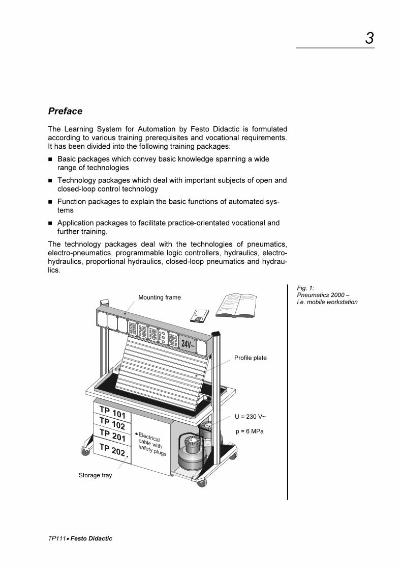
Fig. 1:Pneumatics 2000 –i.e. mobile workstation
Mounting frame
Profile plate
Storage tray
U = 230 V~
p = 6 MPa
TP111� Festo Didactic
4
The modular design of the Learning System permits applications beyondthe scope of the individual packages. It is, for instance, possible to de-sign PLC-controlled systems with pneumatic, hydraulic and electricalactuators.
All training packages are based on an identical structure:
� Hardware
� Teachware
� Software
� Seminars
The hardware consists of industrial components and systems whichhave been adapted for didactic purposes.
The courseware has been designed in line with didactic methods andcoordinated for use with the training hardware. The courseware com-prises:
� Textbooks (with exercises and examples)
� Workbooks (with practical exercises, explanatory notes, solutions anddata sheets)
� Transparencies and videos (to create a lively training environment)
The training and learning media is available in several languages, whichhas been designed for use in the classroom as well as for self-tuition.
The software sector serves as a basis for providing computer trainingprograms and programming software for programmable logic control-lers.
A comprehensive range of seminars on the subject of the various tech-nology packages completes our program of vocational and furthertraining.
TP111� Festo Didactic
5
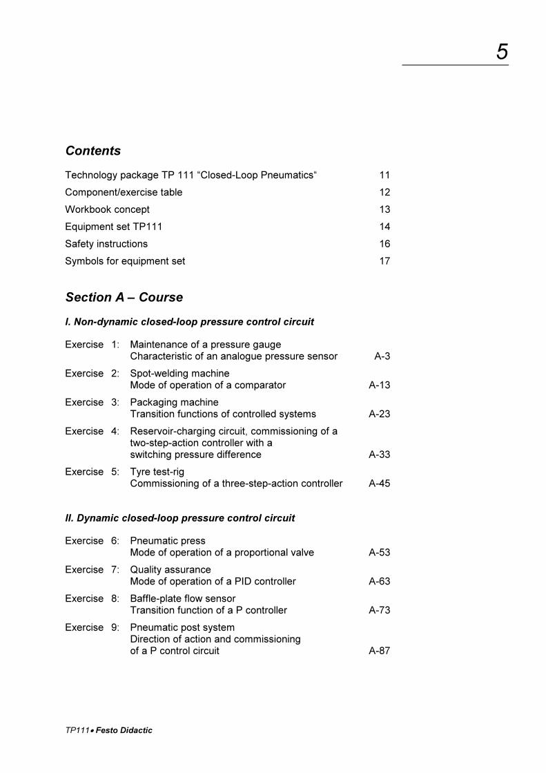
Contents
Technology package TP 111 “Closed-Loop Pneumatics“ 11
Component/exercise table 12
Workbook concept 13
Equipment set TP111 14
Safety instructions 16
Symbols for equipment set 17
Section A – Course
I. Non-dynamic closed-loop pressure control circuit
Exercise 1: Maintenance of a pressure gaugeCharacteristic of an analogue pressure sensor A-3
Exercise 2: Spot-welding machineMode of operation of a comparator A-13
Exercise 3: Packaging machineTransition functions of controlled systems A-23
Exercise 4: Reservoir-charging circuit, commissioning of atwo-step-action controller with aswitching pressure difference A-33
Exercise 5: Tyre test-rigCommissioning of a three-step-action controller A-45
II. Dynamic closed-loop pressure control circuit
Exercise 6: Pneumatic pressMode of operation of a proportional valve A-53
Exercise 7: Quality assuranceMode of operation of a PID controller A-63
Exercise 8: Baffle-plate flow sensorTransition function of a P controller A-73
Exercise 9: Pneumatic post systemDirection of action and commissioningof a P control circuit A-87
TP111� Festo Didactic
6
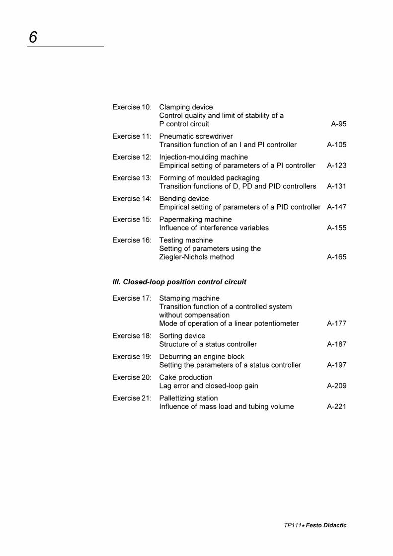
Exercise 10: Clamping deviceControl quality and limit of stability of aP control circuit A-95
Exercise 11: Pneumatic screwdriverTransition function of an I and PI controller A-105
Exercise 12: Injection-moulding machineEmpirical setting of parameters of a PI controller A-123
Exercise 13: Forming of moulded packagingTransition functions of D, PD and PID controllers A-131
Exercise 14: Bending deviceEmpirical setting of parameters of a PID controller A-147
Exercise 15: Papermaking machineInfluence of interference variables A-155
Exercise 16: Testing machineSetting of parameters using theZiegler-Nichols method A-165
III. Closed-loop position control circuit
Exercise 17: Stamping machineTransition function of a controlled system without compensationMode of operation of a linear potentiometer A-177
Exercise 18: Sorting deviceStructure of a status controller A-187
Exercise 19: Deburring an engine blockSetting the parameters of a status controller A-197
Exercise 20: Cake productionLag error and closed-loop gain A-209
Exercise 21: Pallettizing stationInfluence of mass load and tubing volume A-221
TP111� Festo Didactic
7
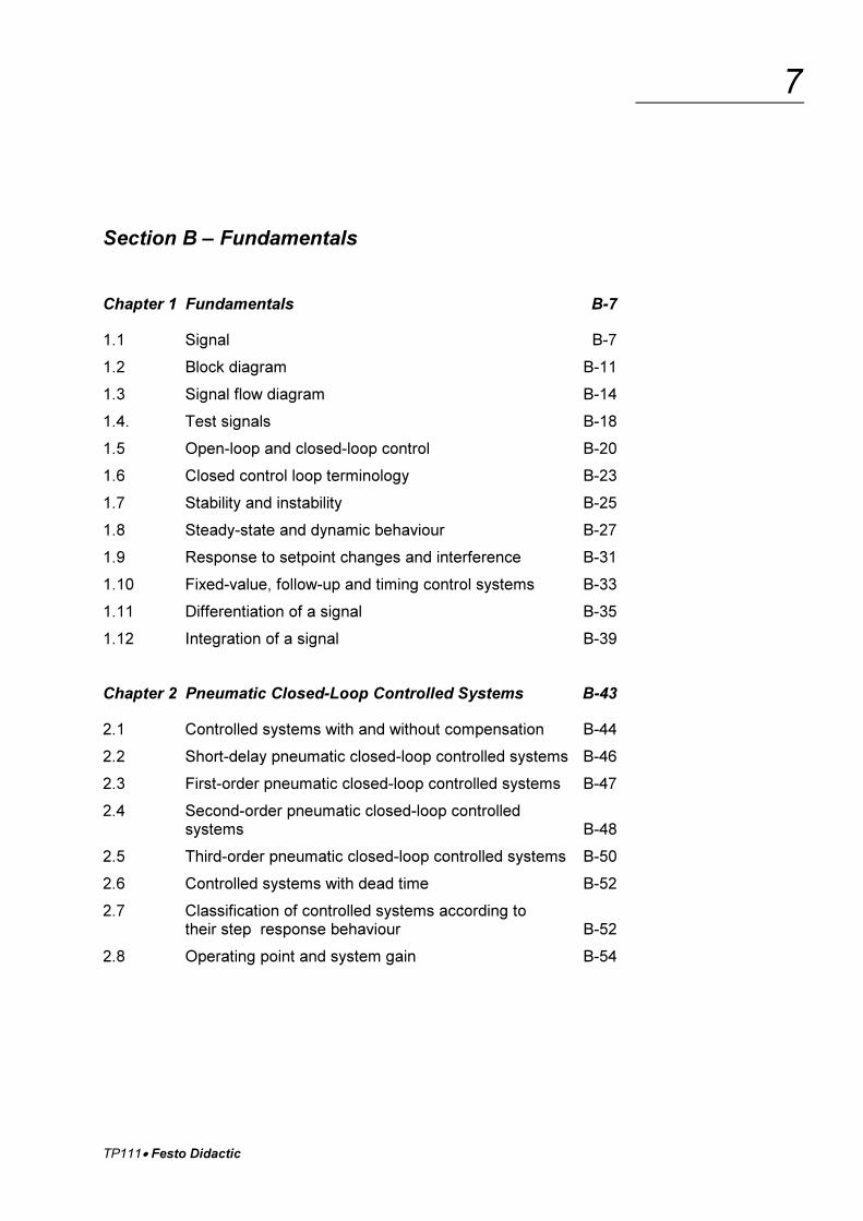
Section B – Fundamentals
Chapter 1 Fundamentals B-7
1.1 Signal B-7
1.2 Block diagram B-11
1.3 Signal flow diagram B-14
1.4. Test signals B-18
1.5 Open-loop and closed-loop control B-20
1.6 Closed control loop terminology B-23
1.7 Stability and instability B-25
1.8 Steady-state and dynamic behaviour B-27
1.9 Response to setpoint changes and interference B-31
1.10 Fixed-value, follow-up and timing control systems B-33
1.11 Differentiation of a signal B-35
1.12 Integration of a signal B-39
Chapter 2 Pneumatic Closed-Loop Controlled Systems B-43
2.1 Controlled systems with and without compensation B-44
2.2 Short-delay pneumatic closed-loop controlled systems B-46
2.3 First-order pneumatic closed-loop controlled systems B-47
2.4 Second-order pneumatic closed-loop controlledsystems B-48
2.5 Third-order pneumatic closed-loop controlled systems B-50
2.6 Controlled systems with dead time B-52
2.7 Classification of controlled systems according totheir step response behaviour B-52
2.8 Operating point and system gain B-54
TP111� Festo Didactic
8
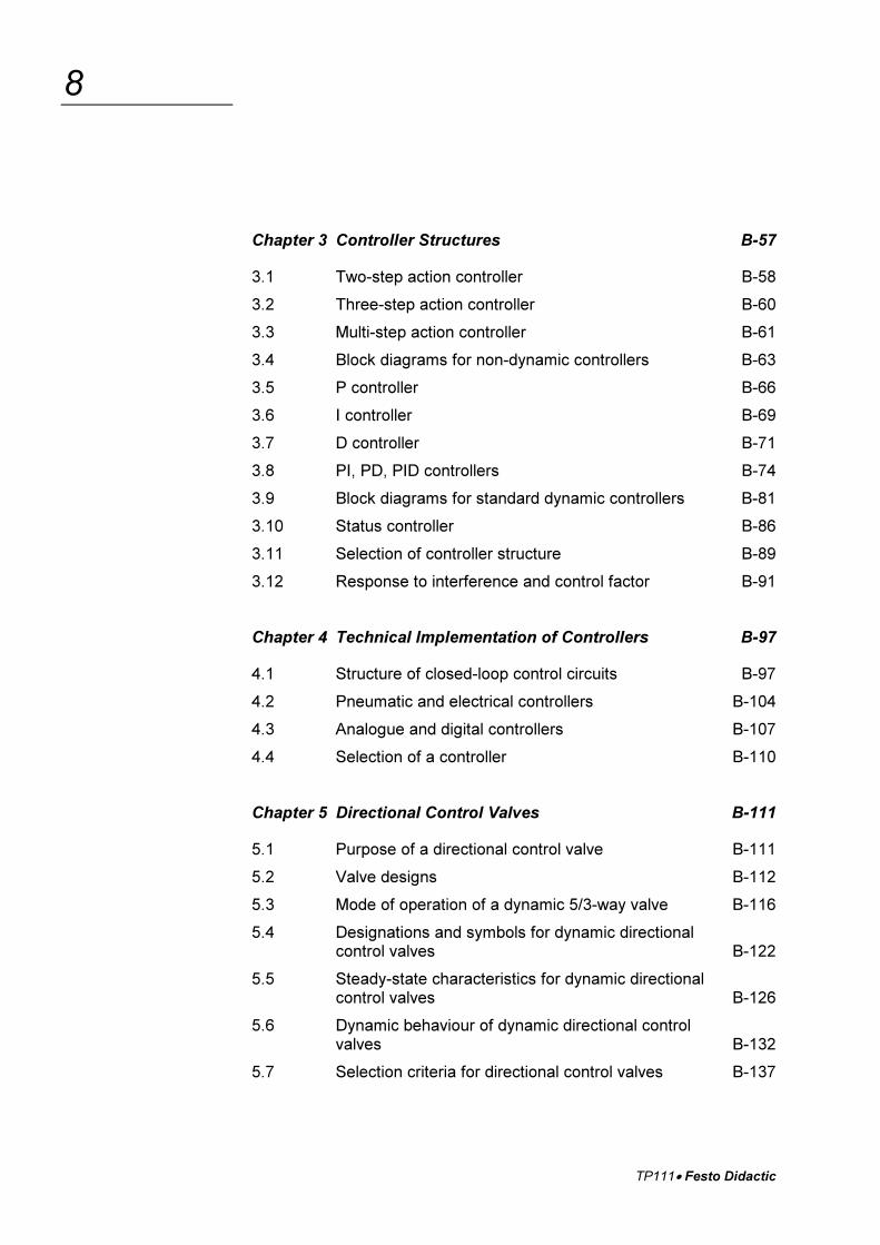
Chapter 3 Controller Structures B-57
3.1 Two-step action controller B-58
3.2 Three-step action controller B-60
3.3 Multi-step action controller B-61
3.4 Block diagrams for non-dynamic controllers B-63
3.5 P controller B-66
3.6 I controller B-69
3.7 D controller B-71
3.8 PI, PD, PID controllers B-74
3.9 Block diagrams for standard dynamic controllers B-81
3.10 Status controller B-86
3.11 Selection of controller structure B-89
3.12 Response to interference and control factor B-91
Chapter 4 Technical Implementation of Controllers B-97
4.1 Structure of closed-loop control circuits B-97
4.2 Pneumatic and electrical controllers B-104
4.3 Analogue and digital controllers B-107
4.4 Selection of a controller B-110
Chapter 5 Directional Control Valves B-111
5.1 Purpose of a directional control valve B-111
5.2 Valve designs B-112
5.3 Mode of operation of a dynamic 5/3-way valve B-116
5.4 Designations and symbols for dynamic directionalcontrol valves B-122
5.5 Steady-state characteristics for dynamic directionalcontrol valves B-126
5.6 Dynamic behaviour of dynamic directional controlvalves B-132
5.7 Selection criteria for directional control valves B-137
TP111� Festo Didactic
9
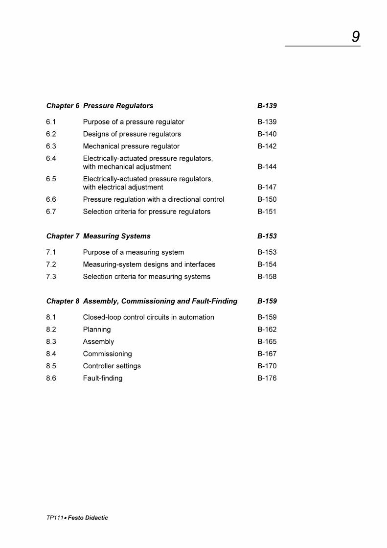
Chapter 6 Pressure Regulators B-139
6.1 Purpose of a pressure regulator B-139
6.2 Designs of pressure regulators B-140
6.3 Mechanical pressure regulator B-142
6.4 Electrically-actuated pressure regulators,with mechanical adjustment B-144
6.5 Electrically-actuated pressure regulators,with electrical adjustment B-147
6.6 Pressure regulation with a directional control B-150
6.7 Selection criteria for pressure regulators B-151
Chapter 7 Measuring Systems B-153
7.1 Purpose of a measuring system B-153
7.2 Measuring-system designs and interfaces B-154
7.3 Selection criteria for measuring systems B-158
Chapter 8 Assembly, Commissioning and Fault-Finding B-159
8.1 Closed-loop control circuits in automation B-159
8.2 Planning B-162
8.3 Assembly B-165
8.4 Commissioning B-167
8.5 Controller settings B-170
8.6 Fault-finding B-176
TP111� Festo Didactic
10
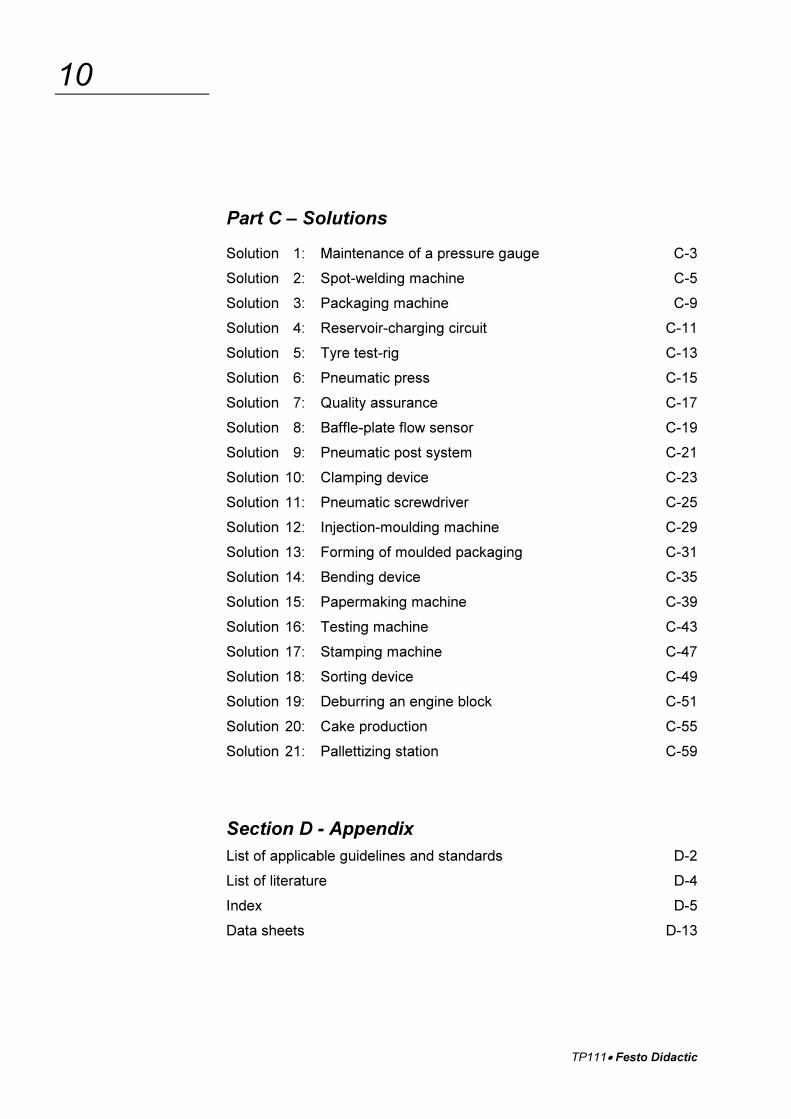
Part C – Solutions
Solution 1: Maintenance of a pressure gauge C-3
Solution 2: Spot-welding machine C-5
Solution 3: Packaging machine C-9
Solution 4: Reservoir-charging circuit C-11
Solution 5: Tyre test-rig C-13
Solution 6: Pneumatic press C-15
Solution 7: Quality assurance C-17
Solution 8: Baffle-plate flow sensor C-19
Solution 9: Pneumatic post system C-21
Solution 10: Clamping device C-23
Solution 11: Pneumatic screwdriver C-25
Solution 12: Injection-moulding machine C-29
Solution 13: Forming of moulded packaging C-31
Solution 14: Bending device C-35
Solution 15: Papermaking machine C-39
Solution 16: Testing machine C-43
Solution 17: Stamping machine C-47
Solution 18: Sorting device C-49
Solution 19: Deburring an engine block C-51
Solution 20: Cake production C-55
Solution 21: Pallettizing station C-59
Section D - Appendix
List of applicable guidelines and standards D-2
List of literature D-4
Index D-5
Data sheets D-13
TP111� Festo Didactic
11
Technology package TP 111
“Closed-Loop Pneumatics“
The technology package TP111 “Closed-Loop Pneumatics” forms partof Festo Didactic’s Learning System for Automation and Communica-tions.
The training aims of TP111 are concerned with analogue closed-loopcontrol technology. Actuators are activated via electrical open andclosed-loop components.
Students working through technology package TP110 should preferablyhave basic knowledge of electropneumatics and measuring systems.
The equipment set is designed in such a way that the number of com-ponents required becomes larger from one exercise to the next. Thismakes it possible to begin a study of closed-loop control technology witha small number of components, which can then be added to as neces-sary.
The exercises of TP111 are concerned with three main subjects:
� Non-dynamic pressure regulation (exercises 1 – 5)
� Dynamic pressure regulation (exercises 6 – 16)
� Position control (exercises 17 – 21)
The components required for particular exercises can be seen in thecomponent/exercise table over leaf.
TP111� Festo Didactic
12
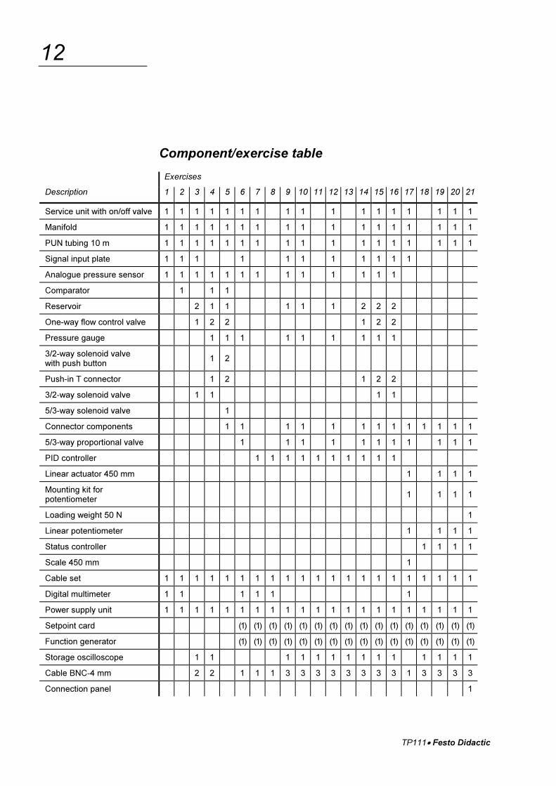
Component/exercise table
Exercises
Description 1 2 3 4 5 6 7 8 9 10 11 12 13 14 15 16 17 18 19 20 21
Service unit with on/off valve 1 1 1 1 1 1 1 1 1 1 1 1 1 1 1 1 1
Manifold 1 1 1 1 1 1 1 1 1 1 1 1 1 1 1 1 1
PUN tubing 10 m 1 1 1 1 1 1 1 1 1 1 1 1 1 1 1 1 1
Signal input plate 1 1 1 1 1 1 1 1 1 1 1
Analogue pressure sensor 1 1 1 1 1 1 1 1 1 1 1 1 1
Comparator 1 1 1
Reservoir 2 1 1 1 1 1 2 2 2
One-way flow control valve 1 2 2 1 2 2
Pressure gauge 1 1 1 1 1 1 1 1 1
3/2-way solenoid valvewith push button
1 2
Push-in T connector 1 2 1 2 2
3/2-way solenoid valve 1 1 1 1
5/3-way solenoid valve 1
Connector components 1 1 1 1 1 1 1 1 1 1 1 1 1
5/3-way proportional valve 1 1 1 1 1 1 1 1 1 1 1
PID controller 1 1 1 1 1 1 1 1 1 1
Linear actuator 450 mm 1 1 1 1
Mounting kit forpotentiometer
1 1 1 1
Loading weight 50 N 1
Linear potentiometer 1 1 1 1
Status controller 1 1 1 1
Scale 450 mm 1
Cable set 1 1 1 1 1 1 1 1 1 1 1 1 1 1 1 1 1 1 1 1 1
Digital multimeter 1 1 1 1 1 1
Power supply unit 1 1 1 1 1 1 1 1 1 1 1 1 1 1 1 1 1 1 1 1 1
Setpoint card (1) (1) (1) (1) (1) (1) (1) (1) (1) (1) (1) (1) (1) (1) (1) (1)
Function generator (1) (1) (1) (1) (1) (1) (1) (1) (1) (1) (1) (1) (1) (1) (1) (1)
Storage oscilloscope 1 1 1 1 1 1 1 1 1 1 1 1 1 1
Cable BNC-4 mm 2 2 1 1 1 3 3 3 3 3 3 3 3 1 3 3 3 3
Connection panel 1
TP111� Festo Didactic
13
Workbook concept
The workbook is divided into the following sections:
Section A – Course
Section B – Fundamentals
Section C – Solutions
Section D – Appendix
In Section A, “Course”, progressive exercises are used to explain theassembly and commissioning of analogue closed-loop control circuits.
The necessary technical knowledge required to complete an exercise isprovided at the start of the exercise concerned. Non-essential detail isavoided. More detailed information is given is Section B.
Section C, “Solutions”, gives the results of the exercises in Section A,with explanatory notes.
Section B, “Fundamentals”, contains general technical knowledgewhich complements the training aims of the exercises in Section A.Theoretical relationships are demonstrated and the necessary specialistterminology is explained in an easily understandable way with examples.
Section D, “Appendix”, is intended for use as a reference work. Itcontains data sheets, a list of literature and an index.
The structure of the book has been designed to allow the use of itscontents both for practical training, e.g. in classroom courses, and forself-study purposes
TP111� Festo Didactic
14
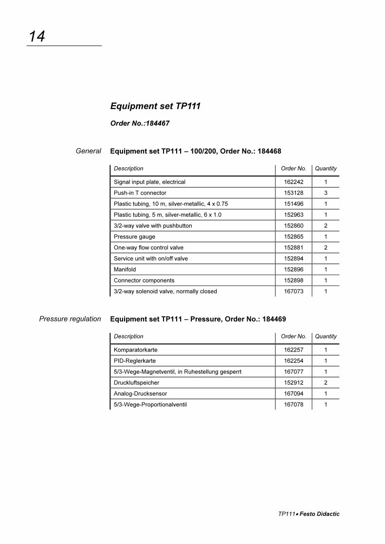
Equipment set TP111
Order No.:184467
Equipment set TP111 – 100/200, Order No.: 184468
Description Order No. Quantity
Signal input plate, electrical 162242 1
Push-in T connector 153128 3
Plastic tubing, 10 m, silver-metallic, 4 x 0.75 151496 1
Plastic tubing, 5 m, silver-metallic, 6 x 1.0 152963 1
3/2-way valve with pushbutton 152860 2
Pressure gauge 152865 1
One-way flow control valve 152881 2
Service unit with on/off valve 152894 1
Manifold 152896 1
Connector components 152898 1
3/2-way solenoid valve, normally closed 167073 1
Equipment set TP111 – Pressure, Order No.: 184469
Description Order No. Quantity
Komparatorkarte 162257 1
PID-Reglerkarte 162254 1
5/3-Wege-Magnetventil, in Ruhestellung gesperrt 167077 1
Druckluftspeicher 152912 2
Analog-Drucksensor 167094 1
5/3-Wege-Proportionalventil 167078 1
General
Pressure regulation
TP111� Festo Didactic
15
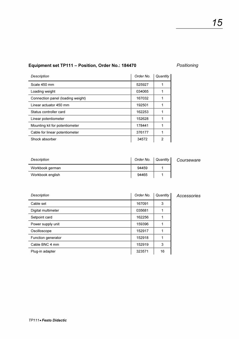
Equipment set TP111 – Position, Order No.: 184470
Description Order No. Quantity
Scale 450 mm 525927 1
Loading weight 034065 1
Connection panel (loading weight) 167032 1
Linear actuator 450 mm 192501 1
Status controller card 162253 1
Linear potentiometer 152628 1
Mounting kit for potentiometer 178441 1
Cable for linear potentiometer 376177 1
Shock absorber 34572 2
Description Order No. Quantity
Workbook german 94459 1
Workbook english 94465 1
Description Order No. Quantity
Cable set 167091 3
Digital multimeter 035681 1
Setpoint card 162256 1
Power supply unit 159396 1
Oscilloscope 152917 1
Function generator 152918 1
Cable BNC 4 mm 152919 3
Plug-in adapter 323571 16
Positioning
Courseware
Accessories
TP111� Festo Didactic
16
Safety instructions
In the interests of your own safety, please follow the instructions givenbelow:
� Mount all components securely on the plate.
� When commissioning control circuits, always switch on first the elec-trical power supply and then the compressed air. When switching off,work in reverse order.
� Do not switch on the compressed air until you have connected upand secured all the tubing.
� Exercise great care when switching on the compressed air. Cylindersmay advance or retract unexpectedly.
� Shut off the compressed air supply immediately if tubing becomesdetached. This will help to prevent accidents.
� Never disconnect tubing while this is under pressure.
� Never exceed the maximum permissible operating pressure of 8 bar.You will need a maximum of 6 bar to carry out the exercises in thecourse.
� Please also observe the general safety instructions of DIN58126 andVDE 100.
� Use only extra-low voltage supplies, maximum 24 V DC.
� Before commissioning closed-loop control circuits, check not only thepneumatic lines but also the electrical cables and connections.
� Please note that the slide of the linear drive is fitted with powerfulmagnets. Do not bring any diskettes or other objects sensitive tomagnetic fields into the vicinity of these magnets.
� Observe the data sheets referring to individual components, particu-larly with regard to safety instructions.
TP111� Festo Didactic
17
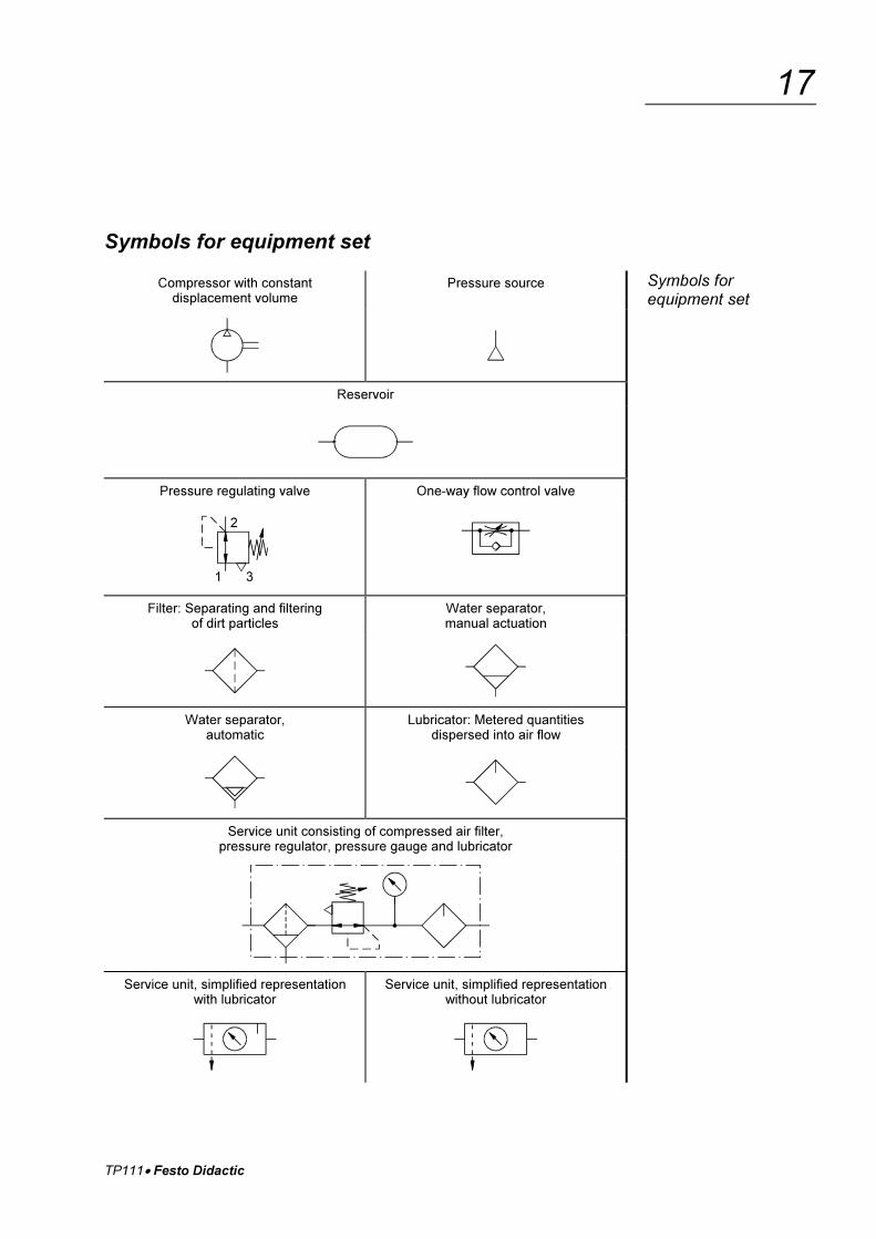
Symbols for equipment set
Compressor with constantdisplacement volume
Pressure source
Reservoir
Pressure regulating valve One-way flow control valve
Filter: Separating and filteringof dirt particles
Water separator,manual actuation
Water separator,automatic
Lubricator: Metered quantitiesdispersed into air flow
Service unit consisting of compressed air filter,pressure regulator, pressure gauge and lubricator
Service unit, simplified representationwith lubricator
Service unit, simplified representationwithout lubricator
Symbols forequipment set

TP111� Festo Didactic
18
Double-acting cylinderwith single-ended piston rod
Double-acting cylinderwith double-ended piston rod
Double-acting cylinder without piston rod Earth/ground
Pressure gauge Shut-off valve
Manual operation Outlet portone threaded connection
Plugged port 3/2-way valvenormally closed
3/3-way valvemid position closed
3/3-way dynamic valvesingle working line
5/2-way valvetwo working lines
5/2-way dynamic valvetwo working lines
5/3-way valvemid position closed
5/3-way dynamic valvetwo working lines
Symbols forequipment set
TP111� Festo Didactic
19
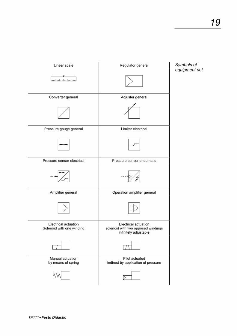
Linear scale Regulator general
Converter general Adjuster general
Pressure gauge general Limiter electrical
Pressure sensor electrical Pressure sensor pneumatic
Amplifier general Operation amplifier general
Electrical actuationSolenoid with one winding
Electrical actuationsolenoid with two opposed windings
infinitely adjustable
Manual actuationby means of spring
Pilot actuatedindirect by application of pressure
Symbols ofequipment set
TP111� Festo Didactic
20
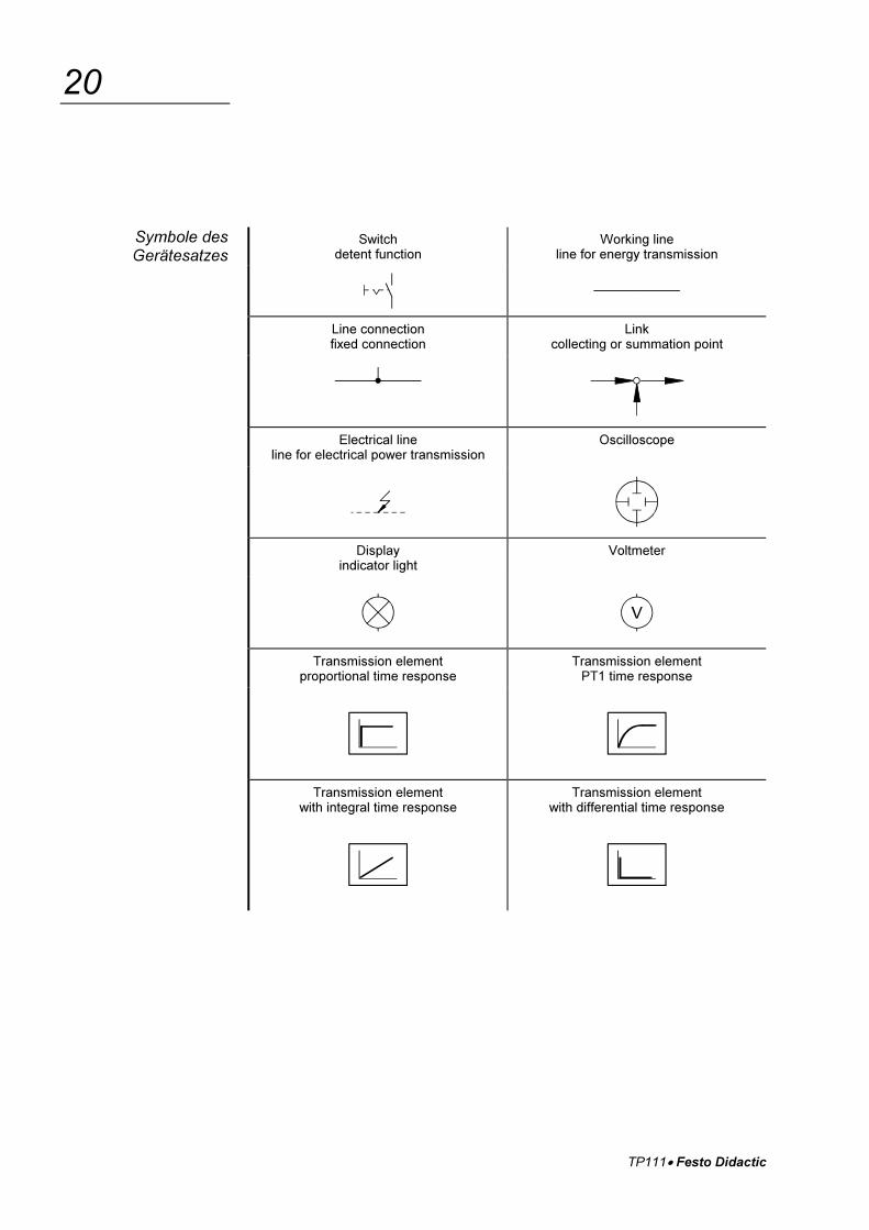
Switchdetent function
Working lineline for energy transmission
Line connectionfixed connection
Linkcollecting or summation point
Electrical lineline for electrical power transmission
Oscilloscope
Displayindicator light
Voltmeter
Transmission elementproportional time response
Transmission elementPT1 time response
Transmission elementwith integral time response
Transmission elementwith differential time response
Symbole desGerätesatzes
TP111� Festo Didactic
21
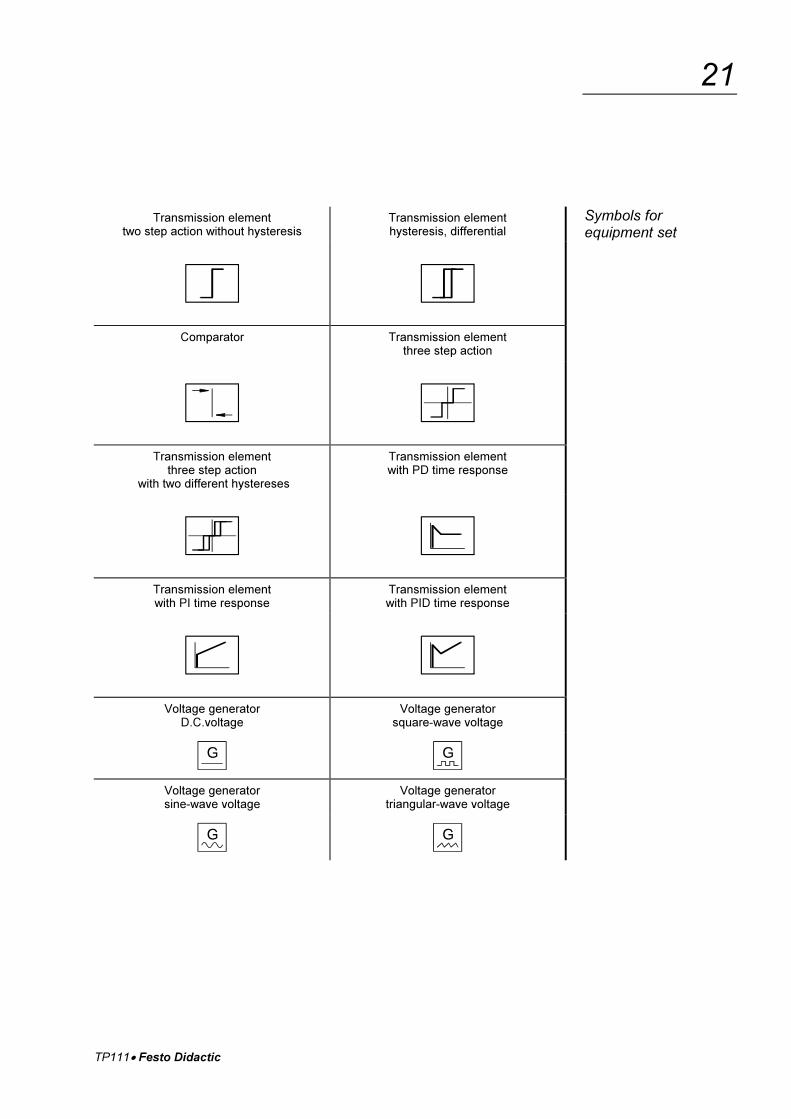
Transmission elementtwo step action without hysteresis
Transmission elementhysteresis, differential
Comparator Transmission elementthree step action
Transmission elementthree step action
with two different hystereses
Transmission elementwith PD time response
Transmission elementwith PI time response
Transmission elementwith PID time response
Voltage generatorD.C.voltage
Voltage generatorsquare-wave voltage
Voltage generatorsine-wave voltage
Voltage generatortriangular-wave voltage
Symbols forequipment set

TP111� Festo Didactic
22
TP111 � Festo Didactic
A-1
Section A – Course
I. Non-dynamic closed-loop pressure control circuit
Exercise 1: Maintenance of a pressure gaugeCharacteristic of an analogue pressure sensor A-3
Exercise 2: Spot-welding machineMode of operation of a comparator A-13
Exercise 3: Packaging machineTransition functions of controlled systems A-23
Exercise 4: Reservoir-charging circuit, commissioning of atwo-step-action controller with aswitching pressure difference A-33
Exercise 5: Tyre test-rigCommissioning of a three-step-action controller A-45
II. Dynamic closed-loop pressure control circuit
Exercise 6: Pneumatic pressMode of operation of a proportional valve A-53
Exercise 7: Quality assuranceMode of operation of a PID controller A-63
Exercise 8: Baffle-plate flow sensorTransition function of a P controller A-73
Exercise 9: Pneumatic post systemDirection of action and commissioningof a P control circuit A-87
Exercise 10: Clamping deviceControl quality and limit of stability of aP control circuit A-95
TP111 � Festo Didactic
A-2
Exercise 11: Pneumatic screwdriverTransition function of an I and PI controller A-105
Exercise 12: Injection-moulding machineEmpirical setting of parameters of a PI controller A-123
Exercise 13: Forming of moulded packagingTransition functions of D, PD and PID controllers A-131
Exercise 14: Bending deviceEmpirical setting of parameters of a PID controller A-147
Exercise 15: Papermaking machineInfluence of interference variables A-155
Exercise 16: Testing machineSetting of parameters using theZiegler-Nichols method A-165
III. Closed-loop position control circuit
Exercise 17: Stamping machineTransition function of a controlled system without compensationMode of operation of a linear potentiometer A-177
Exercise 18: Sorting deviceStructure of a status controller A-187
Exercise 19: Deburring an engine blockSetting the parameters of a status controller A-197
Exercise 20: Cake productionLag error and closed-loop gain A-209
Exercise 21: Pallettizing stationInfluence of mass load and tubing volume A-221
TP111 � Festo Didactic
A-3
Exercise 1
Closed-loop pneumatics
Maintenance of a pressure gauge
� To be able to distinguish between sensors according to their signaltypes
� To be able to explain the design and mode of operation of an ana-logue pressure sensor
� To be able to produce and evaluate characteristics for sensors
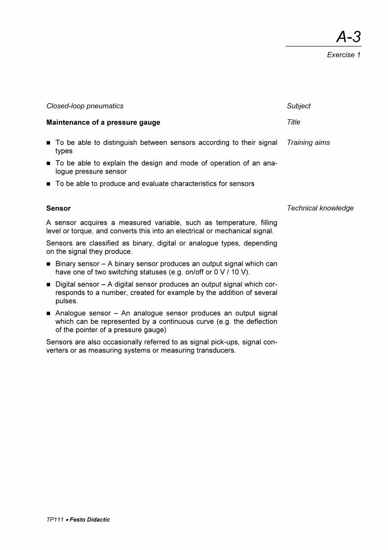
Sensor
A sensor acquires a measured variable, such as temperature, fillinglevel or torque, and converts this into an electrical or mechanical signal.
Sensors are classified as binary, digital or analogue types, dependingon the signal they produce.
� Binary sensor – A binary sensor produces an output signal which canhave one of two switching statuses (e.g. on/off or 0 V / 10 V).
� Digital sensor – A digital sensor produces an output signal which cor-responds to a number, created for example by the addition of severalpulses.
� Analogue sensor – An analogue sensor produces an output signalwhich can be represented by a continuous curve (e.g. the deflectionof the pointer of a pressure gauge)
Sensors are also occasionally referred to as signal pick-ups, signal con-verters or as measuring systems or measuring transducers.
Subject
Title
Training aims
Technical knowledge
TP111 � Festo Didactic
A-4
Exercise 1
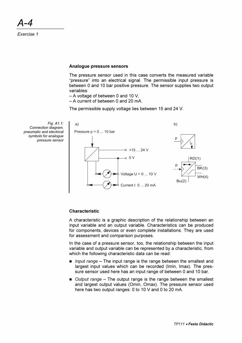
Analogue pressure sensors
The pressure sensor used in this case converts the measured variable“pressure” into an electrical signal. The permissible input pressure isbetween 0 and 10 bar positive pressure. The sensor supplies two outputvariables:– A voltage of between 0 and 10 V,– A current of between 0 and 20 mA.
The permissible supply voltage lies between 15 and 24 V.
Characteristic
A characteristic is a graphic description of the relationship between aninput variable and an output variable. Characteristics can be producedfor components, devices or even complete installations. They are usedfor assessment and comparison purposes.
In the case of a pressure sensor, too, the relationship between the inputvariable and output variable can be represented by a characteristic, fromwhich the following characteristic data can be read:
� Input range – The input range is the range between the smallest andlargest input values which can be recorded (Imin, Imax). The pres-sure sensor used here has an input range of between 0 and 10 bar.
� Output range – The output range is the range between the smallestand largest output values (Omin, Omax). The pressure sensor usedhere has two output ranges: 0 to 10 V and 0 to 20 mA.
Fig. A1.1:Connection diagram,
pneumatic and electricalsymbols for analogue
pressure sensor
TP111 � Festo Didactic
A-5
Exercise 1
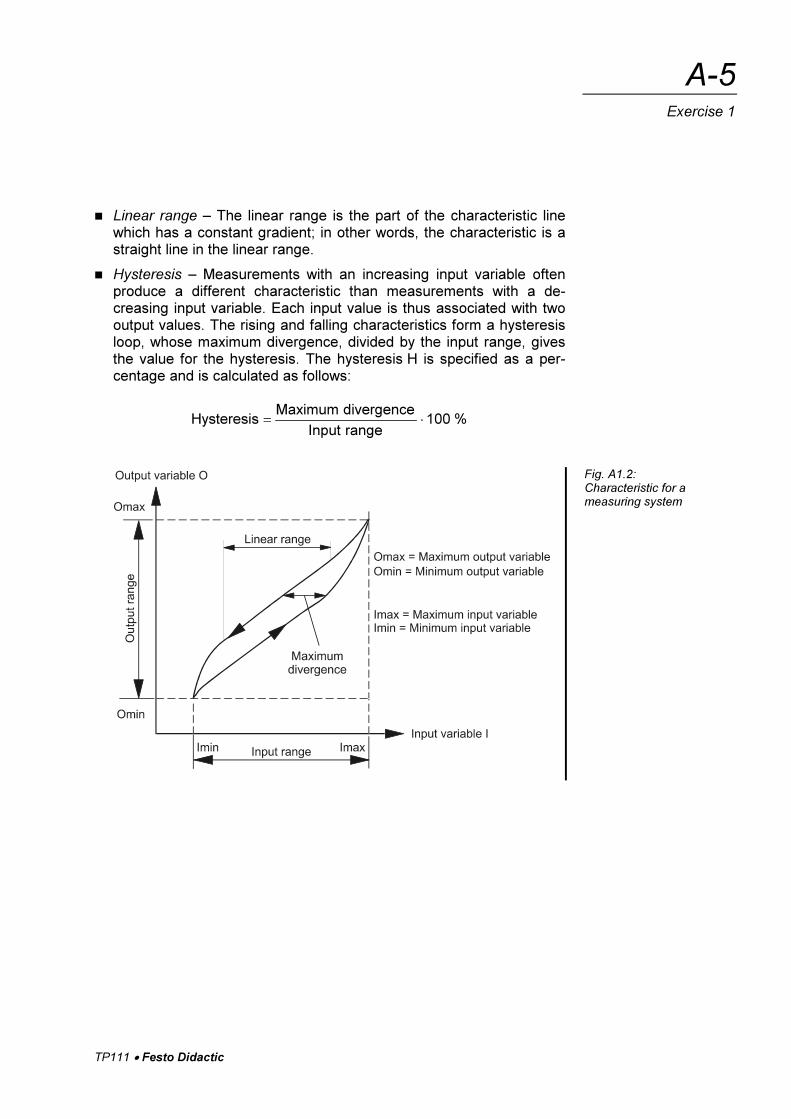
� Linear range – The linear range is the part of the characteristic linewhich has a constant gradient; in other words, the characteristic is astraight line in the linear range.
� Hysteresis – Measurements with an increasing input variable oftenproduce a different characteristic than measurements with a de-creasing input variable. Each input value is thus associated with twooutput values. The rising and falling characteristics form a hysteresisloop, whose maximum divergence, divided by the input range, givesthe value for the hysteresis. The hysteresis H is specified as a per-centage and is calculated as follows:
%100rangeInput
divergenceMaximumHysteresis ��
Fig. A1.2:Characteristic for ameasuring system
TP111 � Festo Didactic
A-6
Exercise 1
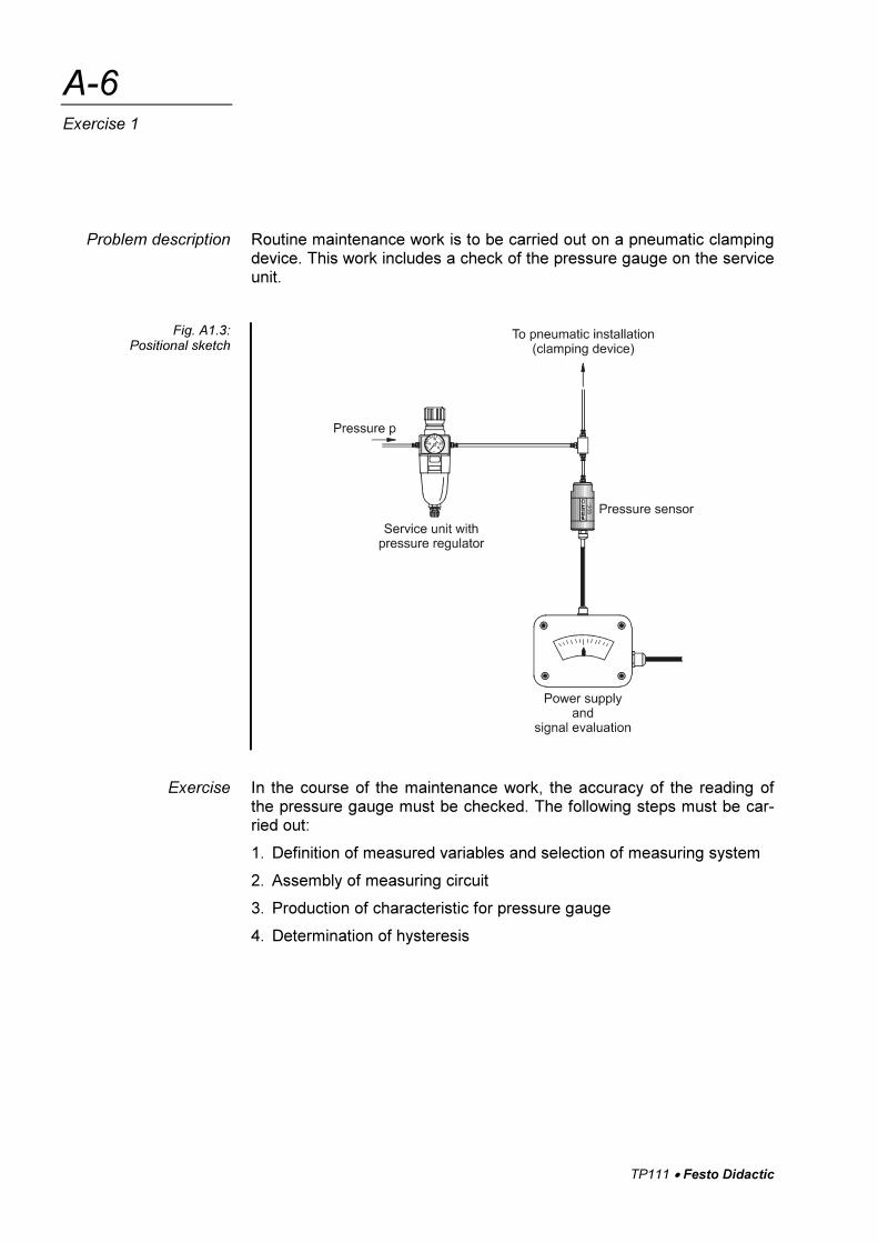
Routine maintenance work is to be carried out on a pneumatic clampingdevice. This work includes a check of the pressure gauge on the serviceunit.
In the course of the maintenance work, the accuracy of the reading ofthe pressure gauge must be checked. The following steps must be car-ried out:
1. Definition of measured variables and selection of measuring system
2. Assembly of measuring circuit
3. Production of characteristic for pressure gauge
4. Determination of hysteresis
Problem description
Fig. A1.3:Positional sketch
Exercise
TP111 � Festo Didactic
A-7
Exercise 1
1.1 Definition of measured variables and selection of measuring
system
� Define the input and output variables of the measuring system. As-sume that the output pressure of the service unit is to be measuredand that you have a voltmeter available to measure the sensor outputsignal. Also specify the associated units for the measured variables.
� Select a measuring system which can handle the input and outputvariables which you have defined.
1.2 Assembly of measuring circuit
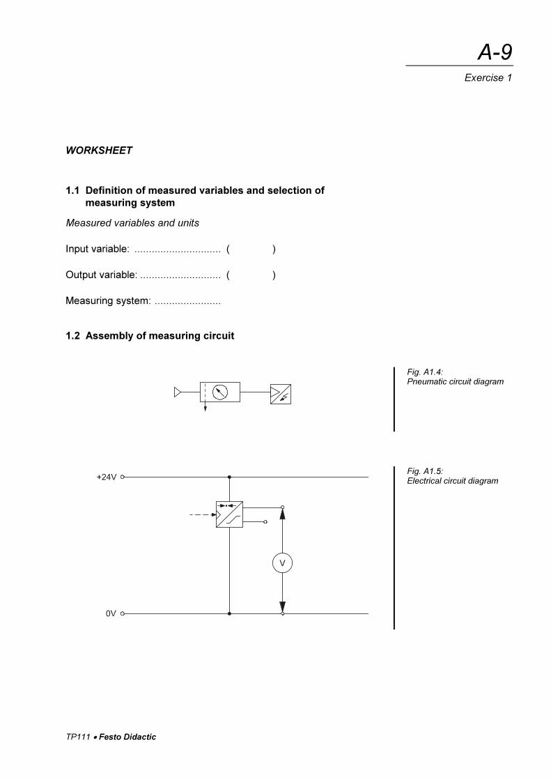
Note the following points with regard to the pneumatic circuit diagram:
� The pressure-gauge function for the pneumatic clamping device isprovided by a service unit with an integral pressure regulator andpressure gauge.
� A pressure sensor is connected directly to the compressed-air outputof the service unit by means of a piece of tubing.
Note the following with regard to the electrical measuring circuit:
� The power supply for the pressure sensor is 24 V.
� A multimeter is used to display the sensor output voltage.
The sockets of the signal input unit are used to connect up the sensorplugs.
Assemble the measuring circuits in accordance with the circuit diagramsprovided.
1.3 Plotting the pressure gauge characteristic
In order to produce the characteristic for the pressure gauge, the outputvoltage of the pressure sensor must be determined and recorded.
� Start the measurements at 0 bar. Then turn the adjusting knob of theservice unit to increase the pressure slowly until the gauge pressurespecified in the worksheet is reached.
Ensure that you go directly to the desired pressure value in order to en-sure that you do not need to turn the adjusting knob back, which wouldreduce the hysteresis.
� Read the measured values carefully and record the values in the ta-ble on the worksheet.
� Take one measurement with rising pressure and one with fallingpressure.
� Then enter the values on the graph provided.
Execution
TP111 � Festo Didactic
A-8
Exercise 1
1.4 Determining the hysteresis
� Determine the maximum divergence between the two measurementcurves.
� Calculate the hysteresis with the aid of the hysteresis equation.
TP111 � Festo Didactic
A-9
Exercise 1
WORKSHEET
1.1 Definition of measured variables and selection of
measuring system
Measured variables and units
Input variable: .............................. ( )
Output variable: ............................ ( )
Measuring system: .......................
1.2 Assembly of measuring circuit
Fig. A1.4:Pneumatic circuit diagram
Fig. A1.5:Electrical circuit diagram
TP111 � Festo Didactic
A-10
Exercise 1
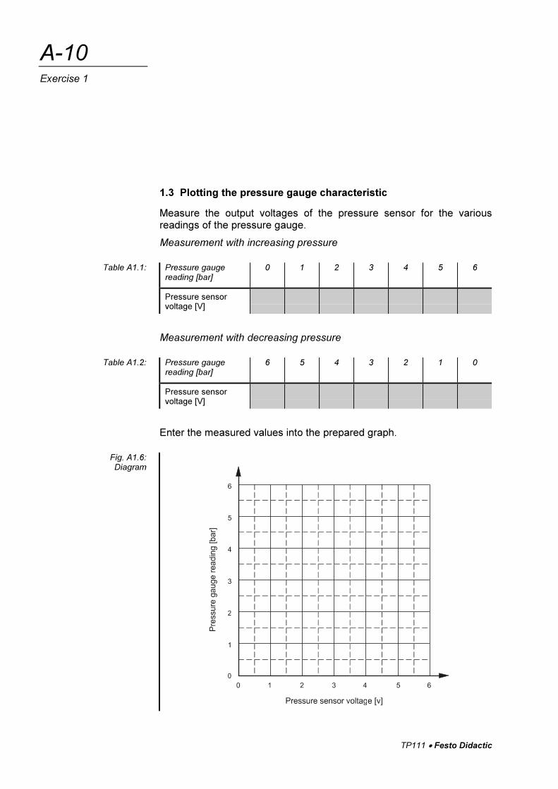
1.3 Plotting the pressure gauge characteristic
Measure the output voltages of the pressure sensor for the variousreadings of the pressure gauge.
Measurement with increasing pressure
Pressure gaugereading [bar]
0 1 2 3 4 5 6
Pressure sensorvoltage [V]
Measurement with decreasing pressure
Pressure gaugereading [bar]
6 5 4 3 2 1 0
Pressure sensorvoltage [V]
Enter the measured values into the prepared graph.
Table A1.1:
Table A1.2:
Fig. A1.6:Diagram
TP111 � Festo Didactic
A-11
Exercise 1
WORKSHEET
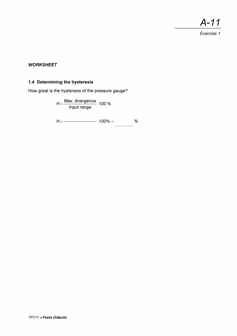
1.4 Determining the hysteresis
How great is the hysteresis of the pressure gauge?
H %100rangeInput
divergence.Max��
H ��� %100...............
%

TP111 � Festo Didactic
A-12
Exercise 1


![[FESTO] Electropneumatics - Workbook Basic Level](https://img.dokumen.tips/doc/110x75/552b9b284a795911588b470d/festo-electropneumatics-workbook-basic-level.jpg)


![[FESTO] Electropneumatics - Basic Level](https://img.dokumen.tips/doc/110x75/552b9b36550346b35d8b46c9/festo-electropneumatics-basic-level.jpg)
