Embed Size (px)
Citation preview

IMpression/Closed Die Forging
Research Report: Material Processing Method
i
APRIL 4, 2014
Name: Theo RidleySt. No.: 100832131

Summary
ii
Table of ContentsSummary____________________________________________________________________ii
List of Figures_______________________________________________________________iii
List of Tables_______________________________________________________________iv
1.0 Main Processes________________________________________________________1
1.1 Overview____________________________________________________________1
1.2 Die Impressions______________________________________________________1
1.3 Flashing Design______________________________________________________2
1.4 Lubrication___________________________________________________________3
2.0 Production Materials___________________________________________________4
2.1 Part Shape___________________________________________________________4
2.2 Die Tolerance________________________________________________________5
2.3 Hot vs Cold Forging__________________________________________________6
3.0 Material Properties of Forged Metal____________________________________8
3.1 Grain Flow by Manufacturing Method_________________________________8
3.2 Grain Flow by Orentation_____________________________________________9
3.3 Defects______________________________________________________________9
4.0 Forging Products_______________________________________________________11
4.1 Connecting Rod______________________________________________________11
4.2 Crankshaft___________________________________________________________12
4.0 Glossary______________________________________________________________13
References_________________________________________________________________14
iii

List of FiguresFigure 1: Example of Fuller and Edger Impressions7_________________________________________1Figure 2: Simple Bender Impression7________________________________________________________2Figure 3: Die Block with Common Impressions2______________________________________________2Figure 4: Flash Land Shape4_________________________________________________________________3Figure 5: Trimmer Die for Connecting Rod8__________________________________________________3Figure 6: Comparison of Friction vs No Friction in Upsetting6_________________________________4Figure 7: Differing Types of Forging Lubrication6_____________________________________________5Figure 8: General Part Shapes for Three Types1______________________________________________7Figure 9: Inner Die Dimensions4_____________________________________________________________7Figure 10: Deformation of Billet in Axisymmetric Die3________________________________________8Figure 11: Comparison of Grain Flow in Bent Bars5___________________________________________9Figure 12: Grain Flow based on Workpiece Orientation7____________________________________10Figure 13:Cold Shut due to Poor Die Radii7_________________________________________________11Figure 14: Connecting Rod Forging Steps3__________________________________________________13Figure 15:Crankshaft Produced in Impression Forging7_____________________________________14
List of TablesTable 1: Shape Groups for Closed Die Forging4______________________________________________4
List of Symbols
iv

1.0 Main ProcessesIn closed die forging, the main process is carried out by hammering or pressing a billet into a die shape. The design of the hammer/press is constrained byto the amount of force and pressure required to forge the part. The shape of the dies are is designed such that metal can reach every corner of the part without creating defects.
1.1OverviewWithin closed die forging, Tthere are two different methods within closed die forging, which that are distinguishedseparated only by their use of flash. Flash is excess metal that is pushed out into flash gutters as the billet is fully compressed. A closed die using flash is referred to as impression die forging, while not using flash is closed die forging in its basic form.
When no flash is used, it is very important that the volume of the forging billet is equal to that of the die shape. If this condition is not met, metal will be pushed out of the die and it will be unable to close.
In order for a part to be forged without defects, it often must be pressed in many intermediate steps to ensure proper grain flow. This requires intermediate dies, which are referred to as “impressions.”
1.2Die ImpressionsDie impressions are used to move metal mass around and shape the part before the final die in order to improve metal flow and prevent the formation of defects.
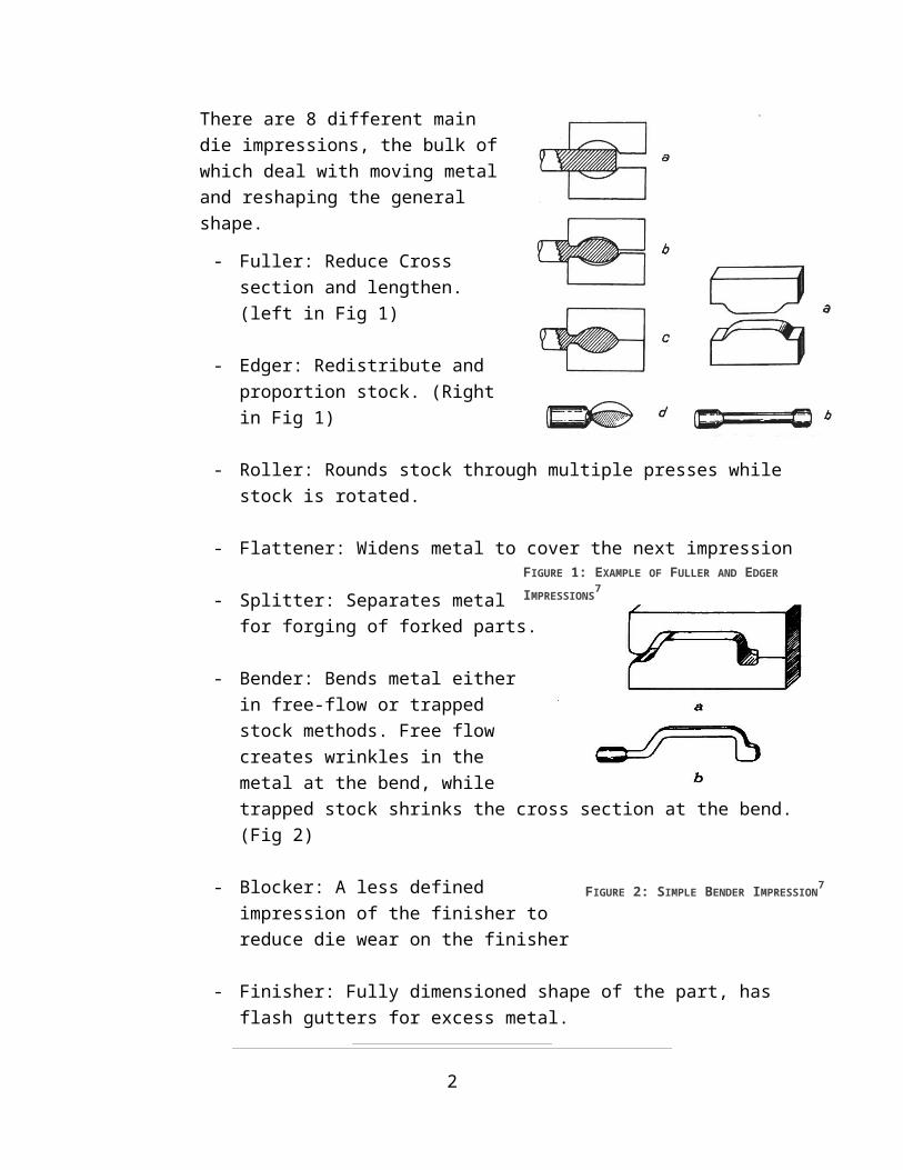
There are 8 different main die impressions, the bulk of which deal with moving metal and reshaping the general shape.
- Fuller: Reduce Cross section and lengthen. (left in Fig 1)
1
- Edger: Redistribute and proportion stock. (Right in Fig 1)
- Roller: Rounds stock through multiple presses while stock is rotated.
- Flattener: Widens metal to cover the next impression
- Splitter: Separates metal for forging of forked parts.
- Bender: Bends metal either in free-flow or trapped stock methods. Free flow creates wrinkles in the metal at the bend, while trapped stock shrinks the cross section at the bend. (Fig 2)
- Blocker: A less defined impression of the finisher to reduce die wear on the finisher
- Finisher: Fully dimensioned shape of the part, has flash gutters for excess metal.
2
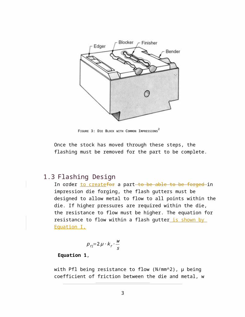
FIGURE 3: DIE BLOCK WITH COMMON IMPRESSIONS2
FIGURE 1: EXAMPLE OF FULLER AND EDGER
IMPRESSIONS7
FIGURE 2: SIMPLE BENDER IMPRESSION7
Once the stock has moved through these steps, the flashing must be removed for the part to be complete.
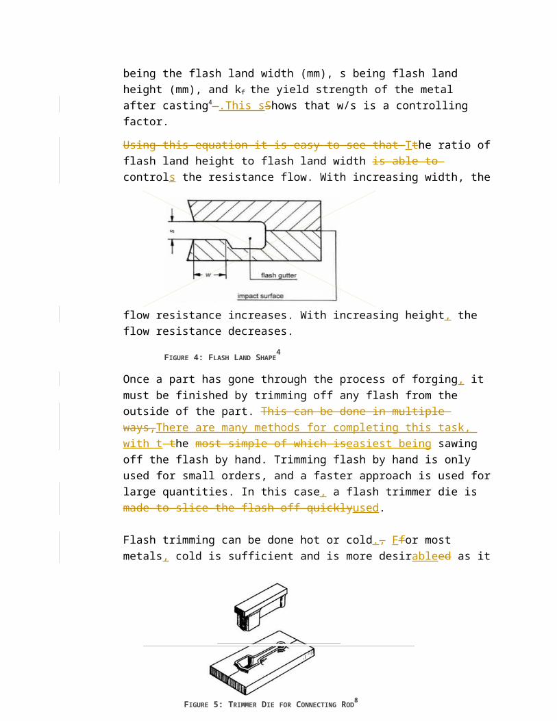
1.3Flashing DesignIn order to createfor a part to be able to be forged in impression die forging, the flash gutters must be designed to allow metal to flow to all points within the die. If higher pressures are required within the die, the resistance to flow must be higher. The equation for resistance to flow within a flash gutter is shown by Equation I,
pfl=2 μ ∙ k f ∙ws
Equation 1,
with Pfl being resistance to flow (N/mm^2), µ being coefficient of friction between the die and metal, w being the flash land width (mm), s being flash land height (mm), and kf the yield strength of the metal after casting4 .This sShows that w/s is a controlling factor.
Using this equation it is easy to see that Tthe ratio of flash land height to flash land width is able to controls the resistance flow. With increasing width, the flow resistance increases. With
increasing height, the flow resistance decreases.
FIGURE 4: FLASH LAND SHAPE4
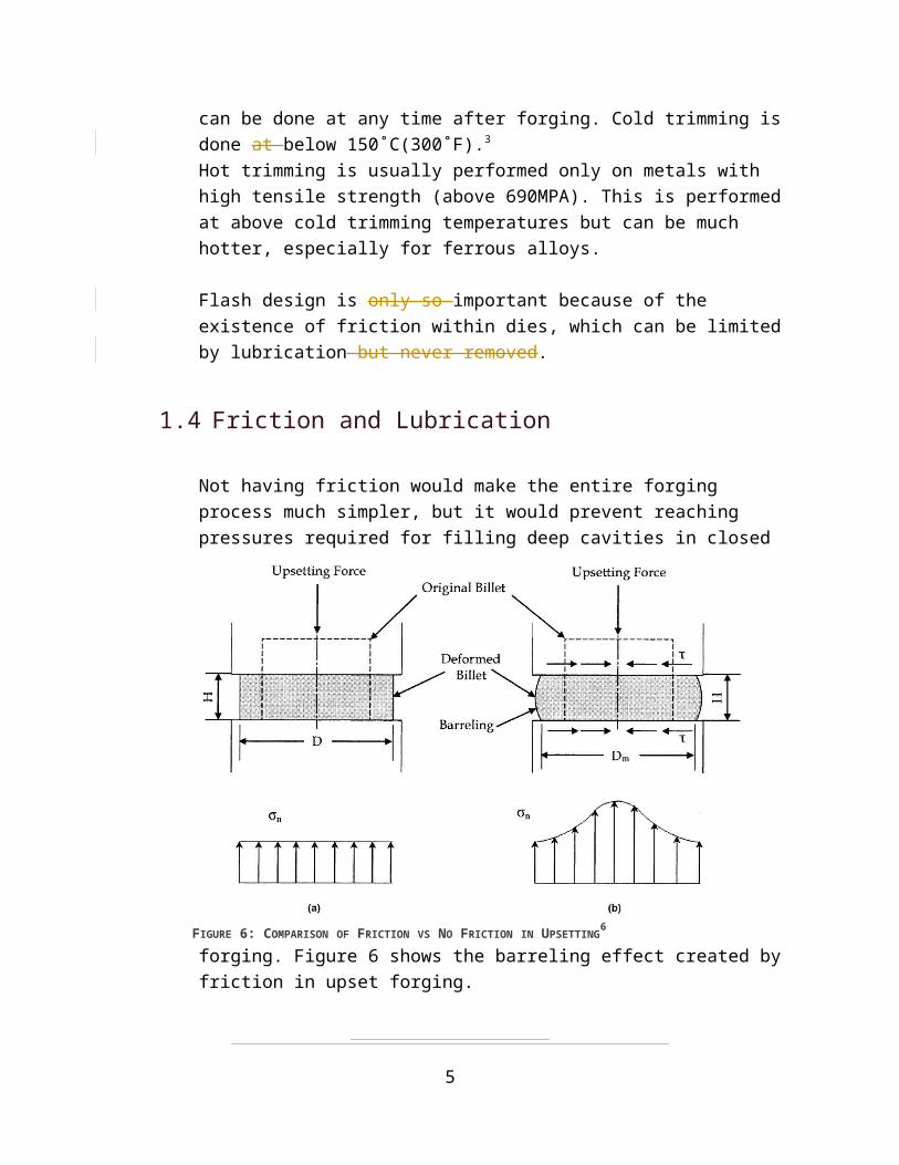
Once a part has gone through the process of forging, it must be finished by trimming off any flash from the outside of the part. This can be done in multiple ways,There are many methods for completing this task, with t the most simple of which iseasiest being sawing off the flash by hand. Trimming flash by hand is only used for small orders, and a faster approach is used for large
3
quantities. In this case, a flash trimmer die is made to slice the flash off quicklyused.
Flash trimming can be done hot or cold., Ffor most metals, cold is sufficient and is more desirableed as it can be done at any time after forging. Cold trimming is done at below 150˚C(300˚F).3
Hot trimming is usually performed only on metals with high tensile strength (above 690MPA). This is performed at above cold trimming temperatures but can be much hotter, especially for ferrous alloys.
Flash design is only so important because of the existence of friction within dies, which can be limited by lubrication but never removed.
1.4Friction and Lubrication
4
FIGURE 5: TRIMMER DIE FOR CONNECTING
ROD8
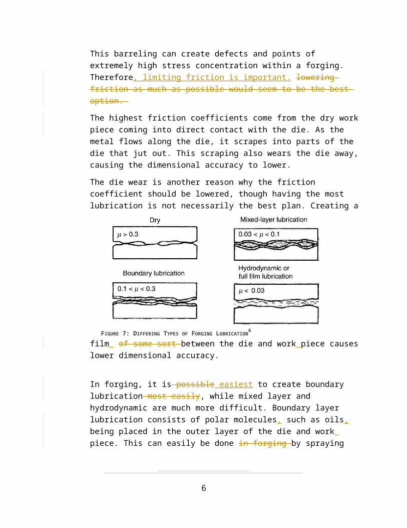
Not having friction would make the entire forging process much simpler, but it would prevent reaching pressures required for filling deep cavities in closed forging. Figure 6 shows the barreling effect
created by friction in upset forging.
This barreling can create defects and points of extremely high stress concentration within a forging. Therefore, limiting friction is important. lowering friction as much as possible would seem to be the best option.
The highest friction coefficients come from the dry work piece coming into direct contact with the die. As the metal flows along the die, it scrapes into parts of the die that jut out. This scraping also wears the die away, causing the dimensional accuracy to lower.
The die wear is another reason why the friction coefficient should be lowered, though having the most lubrication is not necessarily
5
FIGURE 6: COMPARISON OF FRICTION VS NO FRICTION IN UPSETTING6
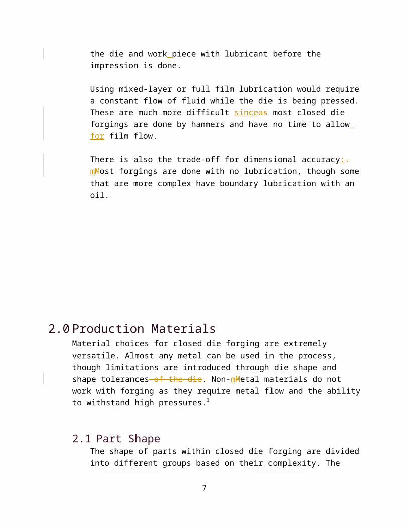
FIGURE 7: DIFFERING TYPES OF FORGING LUBRICATION6
the best plan. Creating a film of some sort between the die and work piece causes lower dimensional accuracy.
In forging, it is possible easiest to create boundary lubrication most easily, while mixed layer and hydrodynamic are much more difficult. Boundary layer lubrication consists of polar molecules, such as oils, being placed in the outer layer of the die and work piece. This can easily be done in forging by spraying the die and work piece with lubricant before the impression is done.
Using mixed-layer or full film lubrication would require a constant flow of fluid while the die is being pressed. These are much more difficult sinceas most closed die forgings are done by hammers and have no time to allow for film flow.
There is also the trade-off for dimensional accuracy:. mMost forgings are done with no lubrication, though some that are more complex have boundary lubrication with an oil.
2.0 Production MaterialsMaterial choices for closed die forging are extremely versatile. Almost any metal can be used in the process, though limitations are introduced through die shape and shape tolerances of the die. Non-mMetal materials do not work with forging as they require metal flow and the ability to withstand high pressures.3
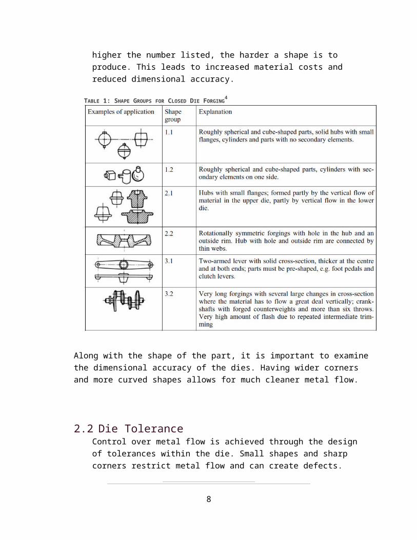
2.1Part ShapeThe shape of parts within closed die forging are divided into different groups based on their complexity. The higher the number
6
listed, the harder a shape is to produce. This leads to increased material costs and reduced dimensional accuracy.
Along with the shape of the part, it is important to examine the dimensional accuracy of the dies. Having wider corners and more curved shapes allows for much cleaner metal flow.
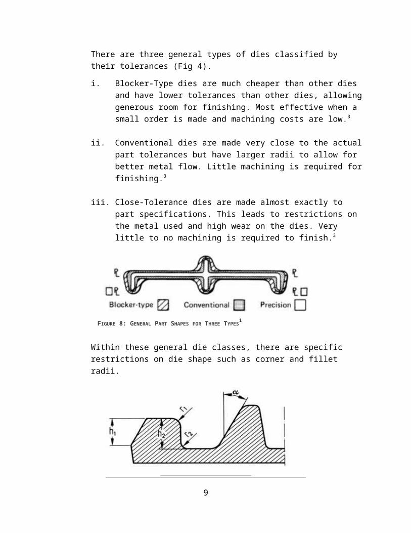
2.2Die ToleranceControl over metal flow is achieved through the design of tolerances within the die. Small shapes and sharp corners restrict metal flow and can create defects. There are three general types of dies classified by their tolerances (Fig 4).
i. Blocker-Type dies are much cheaper than other dies and have lower tolerances than other dies, allowing generous room for finishing. Most effective when a small order is made and machining costs are low.3
7
TABLE 1: SHAPE GROUPS FOR CLOSED DIE FORGING4
ii. Conventional dies are made very close to the actual part tolerances but have larger radii to allow for better metal flow. Little machining is required for finishing.3
iii. Close-Tolerance dies are made almost exactly to part specifications. This leads to restrictions on the metal used and high wear on the dies. Very little to no machining is required to finish.3
Within these general die classes, there are specific restrictions on die shape such as corner and fillet radii.
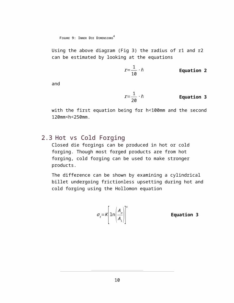
Using the above diagram (Fig 3) the radius of r1 and r2 can be estimated by looking at the equations
r= 110∙h Equation
2
and
r= 120∙h Equation
3
8
FIGURE 9: INNER DIE DIMENSIONS4
FIGURE 8: GENERAL PART SHAPES FOR THREE TYPES1
with the first equation being for h<100mm and the second 120mm<h<250mm.
2.3Hot vs Cold ForgingClosed die forgings can be produced in hot or cold forging. Though most forged products are from hot forging, cold forging can be used to make stronger products.
The difference can be shown by examining a cylindrical billet undergoing frictionless upsetting during hot and cold forging using the Hollomon equation
σ t=K [ ln( AoA1 )]n
Equation 3
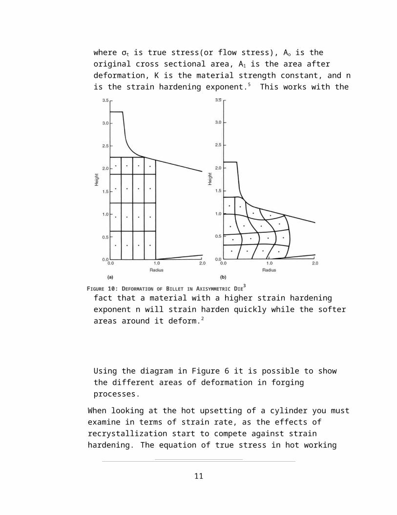
where σt is true stress(or flow stress), Ao is the original cross sectional area, A1 is the area after deformation, K is the material strength constant, and n is the strain hardening exponent.5 This works with the fact that a material with a higher strain hardening
9
FIGURE 10: DEFORMATION OF BILLET IN AXISYMMETRIC DIE3
exponent n will strain harden quickly while the softer areas around it deform.2
Using the diagram in Figure 6 it is possible to show the different areas of deformation in forging processes.
When looking at the hot upsetting of a cylinder you must examine in terms of strain rate, as the effects of recrystallization start to compete against strain hardening. The equation of true stress in hot working
σ t=C ( vh )m
A Equation
4
where σt is true stress, C is strain rate strength constant, m is the strain rate sensitivity exponent, v is the velocity of the die, h is the instantaneous height of the cylinder, and A is the instantaneous area of the cylinder.
This shows a very similar relationship as in cold deformation, only that when in hot deformation the amount of strain hardening is much lower due to the effects of recrystallization.
3.0 Material Properties of Forged MetalForged products have very different material properties from their cast andor machined counterparts. This is due mostly to the flow of grains produced during the forging process. It is also due to strain hardening in the most deformed areas of the metal.
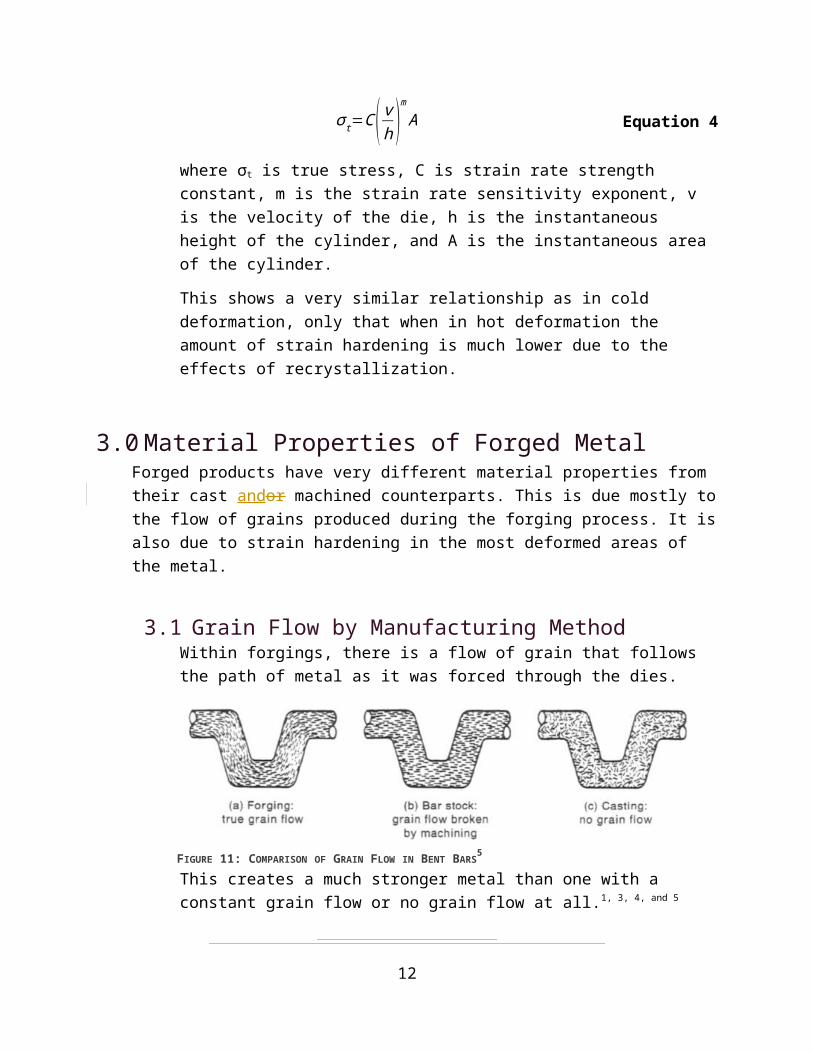
3.1Grain Flow by Manufacturing MethodWithin forgings, there is a flow of grain that follows the path of metal as it was forced through the dies. This creates a much
10FIGURE 11: COMPARISON OF GRAIN FLOW IN BENT BARS5
stronger metal than one with a constant grain flow or no grain flow at all.1, 3, 4, and 5 It can be shown in Figure 6 that a bent bar manufactured through forging has a grain flow that follows the shape of the bar throughout, thus resisting forces that would act against the shape. The machined bar however has a grain that is constant throughout the shape, creating weaker and stronger portions of the bar. In a cast version of the bar, there is no real grain flow due to an equiaxed grain structure.
The conclusion of this data is thatIn conclusion, forging can produce much stronger materials than through other methods, due to the creation of grain flow created. The grain flow can be assisted by the die impression steps to gain the strongest flow possible.
At low temperatures, the friction at the die surfaces causes the grains to stay in place while the rest deform. This friction makes a grain flow that follows very closely to the adheres to the shape of the forging. When forged at higher temperatures, the friction on the die is lower and grains are constantly recrystallizing. From these effects, the grain flow is much less defined and imparts less strength to the finished part.
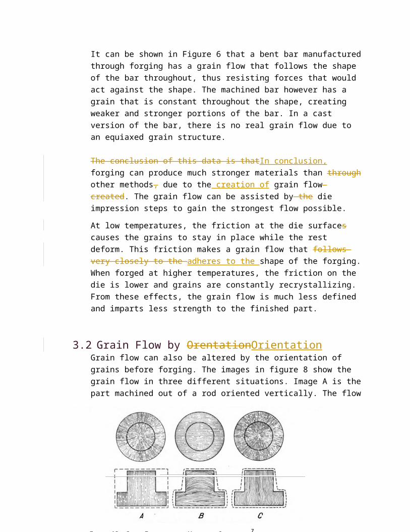
[3.2] Grain Flow by OrentationOrientationGrain flow can also be altered by the orientation of grains before forging. The images in figure 8 show the grain flow in three different situations. Image A is the part machined out of a rod oriented vertically. The flow in image B is created by a rod oriented horizontally to the forging. This causes the flow to follow
11FIGURE 12: GRAIN FLOW BASED ON WORKPIECE ORIENTATION7
in the same path through forging. In image C the rod is vertical and forged.
It is important to note that Wwhile forging can add a grain flow that strengthens the metal, it cannot alter the original orientation of the grains. Hence it is important to align the grains in the direction that imparts the most strength. Which The best option option is best is determined by what the part’s intended purpose is.
3.2[3.3] DefectsDefects within forging can appear due to many factors:
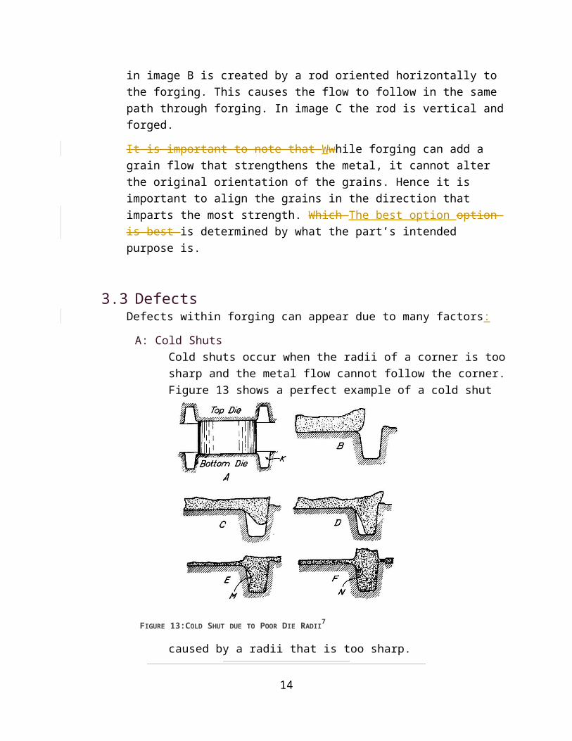
A: Cold ShutsCold shuts occur when the radii of a corner is too sharp and the metal flow cannot follow the corner. Figure 13 shows a perfect example of a cold shut caused by a radii that is too
sharp.
It is clear that between C and D the metal is having a much hard time flowing along the corner into the cavity. In E The cold shut is beginning to form at point M as the metal flowing from above and below meet. In F the metal has moved to point M and a cold shut has been created where the two sides of cold metal shut together. 7
12
FIGURE 13:COLD SHUT DUE TO POOR DIE RADII7
B: CracksCracks are caused by much more material than needed being closed into a finisher impression. For instance, if a large billet is placed directly into the finisher.
They are created after the die cavities fill. Because there is still a large amount of metal to be pushed through the die, the metal that has already filled the die is pushed out. This creates cracks where the cooled metal folds over on the new metal.
C: LapsWhen a blocker impression moves too little material to the webs between bigger impressions, the material in the web can be pushed by the other material to fill up the web. This causes it to fold over on itself as it is pushed. This creates laps periodically along the entire web.7
D: BucklingIf a stock is chosen that is much taller than it is wide, it can buckle under the force of forging instead of just flowing down and out. The entire billet can fold over on itself and ruin the forging.7
4.0 Forging ProductsMost products of metal manufacturing in this day have at least one step involving closed die forging. Some of the most prominent of these are Connecting Rods and Crankshafts for engines.
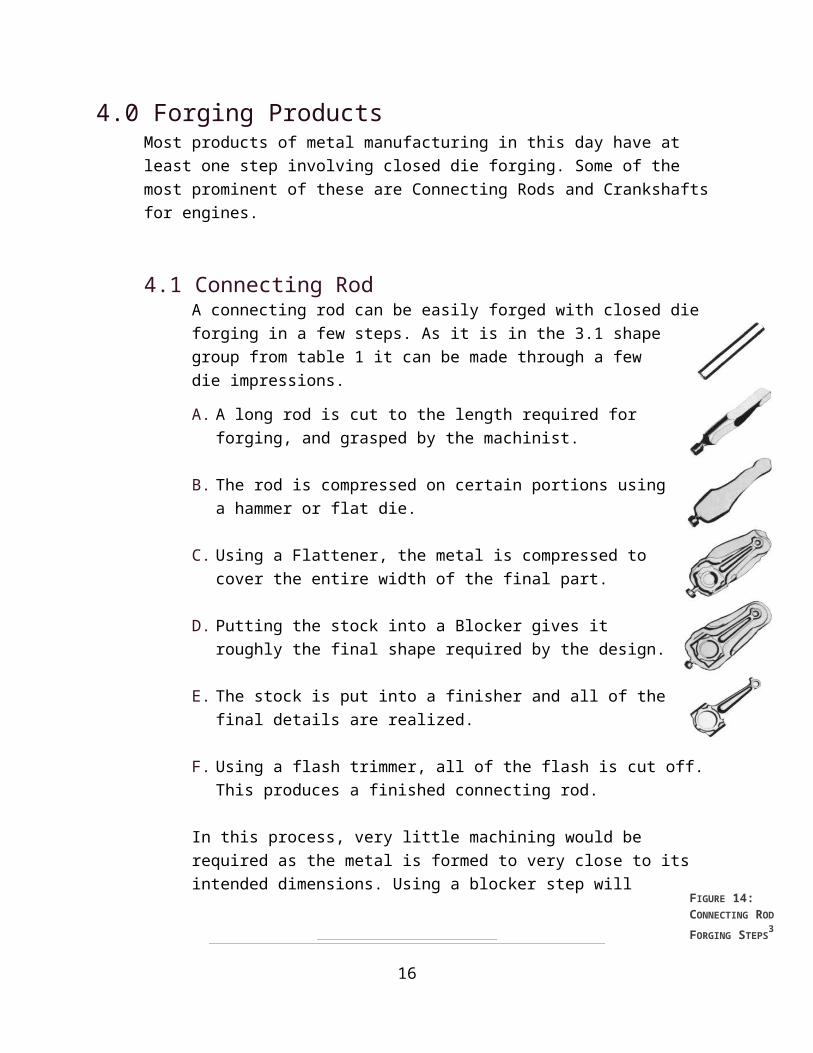
4.1 Connecting RodA connecting rod can be easily forged with closed die forging in a few steps. As it is in the 3.1 shape group from table 1 it can be made through a few die impressions.
A. A long rod is cut to the length required for forging, and grasped by the machinist.
B. The rod is compressed on certain portions using a hammer or flat die.
C. Using a Flattener, the metal is compressed to cover the entire width of the final part.
13
D. Putting the stock into a Blocker gives it roughly the final shape required by the design.
E. The stock is put into a finisher and all of the final details are realized.
F. Using a flash trimmer, all of the flash is cut off. This produces a finished connecting rod.
In this process, very little machining would be required as the metal is formed to very close to its intended dimensions. Using a blocker step will save greatly on material costs for producing dies as the final die will have far less wear.
The grain flow produced by this forging will follow the rod along its length, with some curving around the circular section. This flow should give it great strength against forces acting along its length.
4.2 CrankshaftThe crankshaft of an engine is a very complex part, in the 3.2 shape group. In order to get to the final shape, many steps are required.
The stock in this process is placed in many edgers and fullers, moving the metal around so that it can form each of the counterweights and connecting rod attachments. Within the many steps, it goes through blockers and intermediate trimming steps due to the large amount of flash.
With a forging such as this, close-tolerance dies are rarely used. It is more likely that it would be produced with a blocker-type die and machined afterward.
It is possible to form the entire crankshaft through machining though there is great material waste and costs associated with that method. Using the forging method also creates a stronger crankshaft due to the grain flow created through the rod.
14
FIGURE 14: CONNECTING ROD
FORGING STEPS3
Due to the large number of steps, recrystallization dominates hot casting of crankshafts. This causes the grain flow to be a mixture between a flow following the shape of casting and an equiaxed
grain structure.
4.0 Glossary
15
FIGURE 15:CRANKSHAFT PRODUCED IN IMPRESSION
FORGING7
References
[1]
J.A.Rossow, "Closed Die Forgings," ASM Handbook, vol. 1, no. 10, p. 337–357, 1990.
[2]
R. Shivpuri, "Dies and Die Materials for Hot Forging," ASM Handbook, vol. 14A, pp. 47-61, 2005.
[3]
A. K. Khare, "Forming and Forging," ASM Handbook, vol. 14A, p. 111–118, 2005.
[4]
H. Tschaetsch, "Impression-Die Forging (Closed-Die Forging)," in Metal Forming Practice: Processes - Machines - Tools, Dresden, Springer, 2006,
16
pp. 123-139.
[5]
J. Beddoes, "4.3 Forging," in Principles of Metal Manufacturing Processes, Burlington,MA, Elsevier Butterworth-Heinemann, 1999, pp. 103-115.
[6]
T. Altan, G. Ngaile and G. Shen, "Friction & Lubrication," in Cold and Hot Forging Fundamentals and Apllications, Materials Park, ASM International, 2005, pp. 67-74.
[7]
W. Naujoks and D. C. Fabel, "Forging Practice," in Forging Handbook, Cleveland, OH, American Society for Metals, 1939, pp. 106-205.
[8]
W. Naujoks and D. C. Fabel, "Forge Dies and Tools," in Forging Handbook, Cleveland, OH, American Society for Metals, 1939, pp. 87-105.
17