Embed Size (px)
Citation preview

CityScape Station Installation and Operation Manual
CityScape Spectrum Observatory
CityScape Spectrum Observatory

Page 2 CityScape Spectrum Observatory, CityScape Station Installation and Operation Manual
Contents
0 How To Read This Document ................................................................................................. 4
0.1 For Independent (DIY) Station Deployment ............................................................................................................................. 4
0.2 For Official Station (‘CityScape Traveler’) Deployment ......................................................................................................... 5
0.3 For Third Party Users ......................................................................................................................................................................... 6
1 Introduction ................................................................................................................................... 7
2 Hardware Installation ................................................................................................................. 9
2.1 Antennas ............................................................................................................................................................................................. 10
2.2 Cabling ................................................................................................................................................................................................. 11
2.3 Inside the CityScape Sensor Enclosure .................................................................................................................................... 12
2.3.1 Computer ................................................................................................................................................................ 13
2.3.2 RF Sensor ................................................................................................................................................................ 14
2.3.3 Network Switch ...................................................................................................................................................... 14
2.3.4 Remote Power Switch ........................................................................................................................................... 14
3 System Software Installation and Configuration ......................................................... 15
3.1 Operating System Installation ..................................................................................................................................................... 15
3.2 Network Setup .................................................................................................................................................................................. 15
3.2.1 Hardware Interfaces .............................................................................................................................................. 15
3.2.2 Setting Up the External Network ........................................................................................................................ 16
3.2.3 Setting Up the LAN to the USRP ......................................................................................................................... 16
3.3 USRP (UHD) Software Installation .............................................................................................................................................. 17
3.4 Test USRP Device Setup ................................................................................................................................................................ 18
3.5 USRP Device Calibration ................................................................................................................................................................ 20
3.5.1 UHD Calibration (I-Q Imbalance Correction) .................................................................................................... 21
3.5.2 Amplitude Calibration (for dBm-Scale PSD Estimates) ................................................................................... 22
4 Spectrum Observatory Software Installation ................................................................ 23
4.1 Remove Old Versions, Check Prerequisites ............................................................................................................................ 23
4.2 Spectrum Observatory Measurement Station Installer ...................................................................................................... 24
4.3 Spectrum Data Folder Structure Explained ............................................................................................................................ 25
5 Registering the Station .......................................................................................................... 27

Page 3 CityScape Spectrum Observatory, CityScape Station Installation and Operation Manual
5.1 Making Your Station Known to the Observatory Server ................................................................................................... 27
5.2 Importer Configuration .................................................................................................................................................................. 28
6 Verify Station Installation & Registration ....................................................................... 30
6.1 Checking Service Status ................................................................................................................................................................. 30
7 Station Operation ..................................................................................................................... 31
7.1 RF Sensor Knobs Explained .......................................................................................................................................................... 31
7.1.1 Time averaged PSD ............................................................................................................................................... 31
7.1.2 Raw IQ ..................................................................................................................................................................... 31
7.1.3 Scanner Configuration .......................................................................................................................................... 32
7.1.4 Recommended Settings for the Cityscape Sensor Node ................................................................................ 35
7.2 Viewing or Downloading Uploaded Data From the Web Portal .................................................................................... 36
7.3 Parsing Raw Data Files ................................................................................................................................................................... 40
7.3.1 Using CityScape Project Source .......................................................................................................................... 40
7.3.2 Using Python .......................................................................................................................................................... 41
7.4 Troubleshooting ............................................................................................................................................................................... 41
7.4.1 Station Not Generating or Uploading Data (Gray Station Icon) ................................................................... 41
7.4.2 Uploaded Data (PSD, etc) Does Not Look Right. ............................................................................................. 43
7.4.3 Station Access Key is Lost .................................................................................................................................... 43
7.5 Contributions ..................................................................................................................................................................................... 43
7.5.1 Project Repository ................................................................................................................................................. 43

Page 4 CityScape Spectrum Observatory, CityScape Station Installation and Operation Manual
0 How To Read This Document
This document applies to three categories of audiences:
1. Independent deployers of their own CityScape stations from scratch (i.e. supply their own hardware)
2. Those hosting official CityScape stations at their sites (shipped from SSC) – so that they understand the remaining deployment steps needed.
3. Third party users, seeking only to access archived data from Azure Cloud.
Some sections in this document may not apply to you if you are not deploying a station from scratch. Please see section 0.1 – 0.3 for details.
0.1 For Independent (DIY) Station Deployment
All of Sections 1 to 7 apply to you. You may customize the sensor hardware (described in Section 1 and 2) at your own risk. Please note that your stations will not be able to generate PSD estimates in dBm scale unless you complete a calibration yourself for the specific hardware at your end; please see Section 3.5 for further details.
Deployment flow:

Page 5 CityScape Spectrum Observatory, CityScape Station Installation and Operation Manual
0.2 For Official Station (‘CityScape Traveler’) Deployment
Section 1 – 2, Section 5, and Section 7 apply to you. The rest of the steps are already done for you.
Hardware Build (Sec 2)
OS, USRP Driver Installation (Sec 3)
Sensor Calibration (Sec 3.5)
Station Software Installation (Sec 4)
Station Registration (Sec 5)
Verification (Sec 6)
Site Survey (Recommended)

Page 6 CityScape Spectrum Observatory, CityScape Station Installation and Operation Manual
Deployment flow:
0.3 For Third Party Users
Only Section 1 (introduction) and Section 7 (operation guide) apply to you.
Station Registration (Sec 5)
Verification (Sec 6)
Accept Loan Agreement
Site Survey, Hardware Installation (Done by SSC)
Page 7 CityScape Spectrum Observatory, CityScape Station Installation and Operation Manual
1 Introduction
The CityScape Spectrum Observatory (pilot) project is sponsored by National Science Foundation (NSF) CISE Directorate and executed jointly by U. Washington Fundamentals of Networking Lab (www.ee.washington.edu/research/funlab) and Shared Spectrum Company (www.sharedspectrum.com), with support from Microsoft Corpn. While this effort leverages the earlier Microsoft Spectrum Observatory (https://observatory.microsoftspectrum.com), all the software is Open Source and the collected data is archived on public Azure Cloud (courtesy Microsoft Azure Last Mile Connectivity Group for the duration of the pilot) and released to the spectrum R&D community (with adequate security controls exercised by the Station Administrators).
The focus of CityScape Observatory stations is to provide a new flexible and robust distributed sensor infrastructure that collects and archives raw I-Q sensor data for subsequent processing by the user community. As part of this effort, measurement stations are being installed at various metro locations. This manual – intended for new Station Administrators - provides step-by-step instructions to set up a new CityScape Observatory station.
Hardware Specifications Following are the hardware specifications of the CityScape Spectrum Observatory station set:
Component Type Specification
Dimensions 7ft x 7ft.
Weight Approx. 100lbs.
Mounting The sensor is mounted using a ROHN FRM125 Non-Penetrating Roof Mount with 1.25" x 60" mast. Cinder blocks are used to secure the roof mount.
If the building already has a mast, then the Roof Mount will not be used, and the sensor will be mounted on the existing mast.
Enclosure Hoffman Junction Box, Continuous Hinge with Clamps, EMC, Type 12 (cooling fan attached).
Host PC (in Enclosure) Asus UN62 mini PC. Intel i5 4210U CPU, 16GB DDR3 RAM, 120GByte SSD. Realtek 10/100/1000Base-T LAN (internal), one USB LAN.

Page 8 CityScape Spectrum Observatory, CityScape Station Installation and Operation Manual
RF Sensors (in Enclosure) Ettus Research USRP N200 with UBX40 daughterboard.
Antenna Diamond 130J Discone Antenna (25-1300MHz). PCTEL Maxrad PCTUWB-W Discone Antenna (698Mhz-6GHz).
Misc. Remote power switch included (for remote system reset).
Operating System Windows Server 2012 R2.
Solution Software CityScape Spectrum Observatory Station software.
Internet Connection Standard Ethernet connector (RJ45). 5m, double shielded Ethernet cable provided. Min. download/upload speeds: 500 Kbps / 2 Mbps. Recommended download/upload speeds: 2 Mbps / 8 Mbps.
Power Requirements Standard US 110V AC power. Average power draw : approx. 10W. The enclosure connector is a Power EMI filter, Schaffner EMC Inc.,
FN9244-3-06. A power cord is provided.

Page 9 CityScape Spectrum Observatory, CityScape Station Installation and Operation Manual
2 Hardware Installation
The CityScape station hardware is contained within an environmentally protected Hoffman electrical box. It is installed on the building rooftop alongside the antennas using either a ROHN FRM125 non-penetrating roof mount with a 1.25” x 60” mast (see Figure 1) or pre-existing mast. The installation of the CityScape Station requires access to both power and a Ethernet network connection. Figure 1 shows the set-up and dimensions for one of the CityScape sensors using the non-penetrating roof mount.
Dimensions: 7ft x 7ft.
Weight: ~ 100 pounds.
Figure 1: Typical configuration of CityScape station sensor.
Page 10 CityScape Spectrum Observatory, CityScape Station Installation and Operation Manual
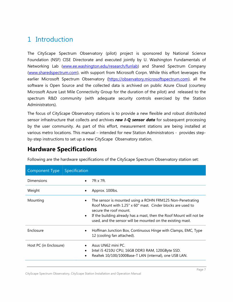
2.1 Antennas
The sensor uses two different antennas for different frequency bands.
DIAMOND D-130J Antenna
This antenna covers the frequency range 25 MHz – 1300 MHz. There is an accompanying 6 ft N Male to N Male RF cable. This requires that the antenna be installed either on the non-penetrating roof mount or a nearby mast.
Mount: Mast mounted
Connection: Type-N connection. Connect to receptacle labeled “RF 1” on bottom of CityScape box.
http://www.diamondantenna.net/picts/D3000N_L.jpg
PCTEL Maxrad PCTUWB-W Discone Antenna This antenna covers the frequency range 698 MHz – 6000 MHz and needs to be installed in such a way that the dome is facing downward (opposite as shown in the picture below). There is a long (~20 ft) cable attached to antenna allowing it to be installed further from the CityScape Station box if needed.
Mount: ¾-inch stud mount with slotted nut. Needs to be mounted on a flat surface. Connection: SMA Male. Connect to receptacle labeled “RF 2” on bottom of CityScape box.

Page 11 CityScape Spectrum Observatory, CityScape Station Installation and Operation Manual
2.2 Cabling
Power
There should be one outlet with 110 V AC power available for the CityScape sensor and the power should be surge protected. The sensor includes a short (~4ft) power cord that plugs to the enclosure connector. The enclosure connector is a Power EMI filter, Schaffner EMC Inc., FN9244-3-06. The sensor uses approximately 10 W of power with an estimate 110 V current of less than 1 amp.
Ethernet
A 5 m double shielded Ethernet cable (Comec 17-101314) is provided to connect to the CityScape sensor. The station administrator may need more cable to connect to the internet backhaul.

Page 12 CityScape Spectrum Observatory, CityScape Station Installation and Operation Manual
2.3 Inside the CityScape Sensor Enclosure
The sensor contains a PC computer, an Ettus Research USRP (as the sensor) and remote power power switch. The remote power switch enables the entire sensor to be rebooted remotely in case of software issues. The enclosure includes a temperature controlled fan to cool the electronics.
5
2
3
4
6 7 8 9 10
1. Asus PC2. Remote Power Switch3. Ettus USRP N2004. 3 Outlet Power Strip5. GB Ethernet Switch/Router6. SMA Female/SMA Female
Receptacle7. SMA Female/N Female Receptacle8. Fan/Temperature controller9. Ethernet Receptacle10. 110 V power/EMI filter11. USB/Ethernet Adapter
Front 11
RF Cable
Ethernet/Internet
Power1
Figure 2: Diagram of the enclosure layout.
Page 13 CityScape Spectrum Observatory, CityScape Station Installation and Operation Manual
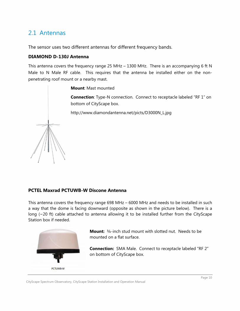
A photograph of the sensor components is shown below. The components are securely mounted to the enclosure walls. The fan and all penetrations are on the bottom. The enclousure has EMI and environmental seals on the door. The EMI shielding prevents RF noise from the components to impact the spectrum measurements.
g
2.3.1 Computer
The computer installed is an ASUS Vivo Mini UN62-M037M, Intel Core i5 4210U, supports 32 GB/128GB/256GB mSATA SSD, Intel HD Graphics 4400, Black Color, No OS. There is an HDMI cable already connected to the computer so the user can connect to the computer because it is difficult to reach within the enclosure.
Figure 3: Photo of the inside of the CityScape sensor enclosure.

Page 14 CityScape Spectrum Observatory, CityScape Station Installation and Operation Manual
2.3.2 RF Sensor
The RF sensor installed is a Ettus USRP N200. The UBX 40 USRP Daughterboard is installed within this component in a manner shown in Figure 4.
Source: https://kb.ettus.com/File:Nseries_wbx_figure_11.png
2.3.3 Network Switch
The network switch installed is a Netgear GS105 Prosafe 5-port Gigabit Switch.
2.3.4 Remote Power Switch
The remote power switch installed is a 3Gstore Remote Power IP Switch with 2 outlets. The two outlets are used for the USRP N200 and the ASUS computer power supplies. The outlets are labeled to show which power supply is to be plugged into each one, with the USRP N200 on the left, and ASUS PC on the right.
Figure 4: Configuration of the wires connected to the UBX 40 Daugtherboard within the USRP N200.

Page 15 CityScape Spectrum Observatory, CityScape Station Installation and Operation Manual
3 System Software Installation and Configuration
This section outlines the setup of the host machine OS, its network interfaces, and the USRP interface drivers and libraries.
When you receive an assembled Cityscape Sensor Node, these system software installations will already have been performed. This manual section is informational and refers to the default, pre-installed system software set. Variations are possible, but step by step instructions are not available in those cases. The only officially supported system software set is the one supplied by Shared Spectrum Corporation.
3.1 Operating System Installation
The supported operating systems are Windows Server 2012 R2 or later, and Windows 8.1 or later. Windows Server 2012 R2 is installed on the Sensor Nodes in the Cityscape Pilot.
If Windows 8.1 or later is used, please make sure that the PC never goes to sleep either by changing the sleep settings or running an application that keeps the PC awake all the time.
3.2 Network Setup
Please note that an Internet connection for the host PC is required with recommended upload speed of 8Mbps or higher. The Internet connection will be used to upload the captured data to the cloud for further analysis, sharing and presentation.
3.2.1 Hardware Interfaces
The station comes with:
USB Ethernet Adapter for Internet connection. Waterproof Ethernet port (mounted on the enclosure) and cable.
The station requires:

Page 16 CityScape Spectrum Observatory, CityScape Station Installation and Operation Manual
1 wired Ethernet connection with Internet access.
3.2.2 Setting Up the External Network
Connect the station’s USB Ethernet Adapter to the Internet-capable Ethernet network.
3.2.3 Setting Up the LAN to the USRP
*Please make sure that the network adapters are correctly recognized and are using up-to-date drivers from the manufacturer before progressing. USRP is very sensitive to the Ethernet hardware & driver performance.
1. Right-click on the network icon from System Tray
2. Click on the Open Network and Sharing Center 3. Click on Change Adapter Settings 4. Right-click the host PC’s Gigabit Ethernet adapter (not the USB-to-Ethernet bridge),
and then click Properties
Figure 5: Station Network Configuration Diagram
Figure 5: Station Network Configuration Diagram
Page 17 CityScape Spectrum Observatory, CityScape Station Installation and Operation Manual
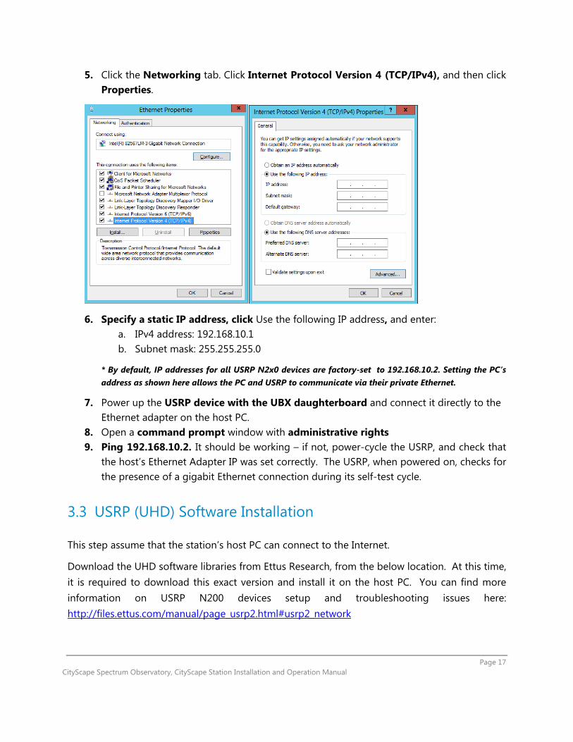
5. Click the Networking tab. Click Internet Protocol Version 4 (TCP/IPv4), and then click Properties.
6. Specify a static IP address, click Use the following IP address, and enter: a. IPv4 address: 192.168.10.1 b. Subnet mask: 255.255.255.0
* By default, IP addresses for all USRP N2x0 devices are factory-set to 192.168.10.2. Setting the PC’s address as shown here allows the PC and USRP to communicate via their private Ethernet.
7. Power up the USRP device with the UBX daughterboard and connect it directly to the Ethernet adapter on the host PC.
8. Open a command prompt window with administrative rights 9. Ping 192.168.10.2. It should be working – if not, power-cycle the USRP, and check that
the host’s Ethernet Adapter IP was set correctly. The USRP, when powered on, checks for the presence of a gigabit Ethernet connection during its self-test cycle.
3.3 USRP (UHD) Software Installation
This step assume that the station’s host PC can connect to the Internet.
Download the UHD software libraries from Ettus Research, from the below location. At this time, it is required to download this exact version and install it on the host PC. You can find more information on USRP N200 devices setup and troubleshooting issues here: http://files.ettus.com/manual/page_usrp2.html#usrp2_network

Page 18 CityScape Spectrum Observatory, CityScape Station Installation and Operation Manual
URL: http://files.ettus.com/binaries/uhd_stable/uhd_003.008.005-release/uhd_003.008.005-release_Win64_VS2013.exe File Name: uhd_003.008.005-release_Win64_VS2013.exe Launch the UHD executable Choose the default install location Select Add UHD to the system PATH for all users, from the installation wizard as given
below: Once the installation is complete, close the UHD Setup dialog.
3.4 Test USRP Device Setup
It is assumed that the ping test in Section 3.2.3 was successful, the commands in this Section will verify higher-level software communication between the host PC and the USRP. All the commands are required to be successfully completed and the output appear on the console as shown.
<install-path>\bin\uhd_find_devices.exe
Figure 6: UHD Software Installation Wizard

Page 19 CityScape Spectrum Observatory, CityScape Station Installation and Operation Manual
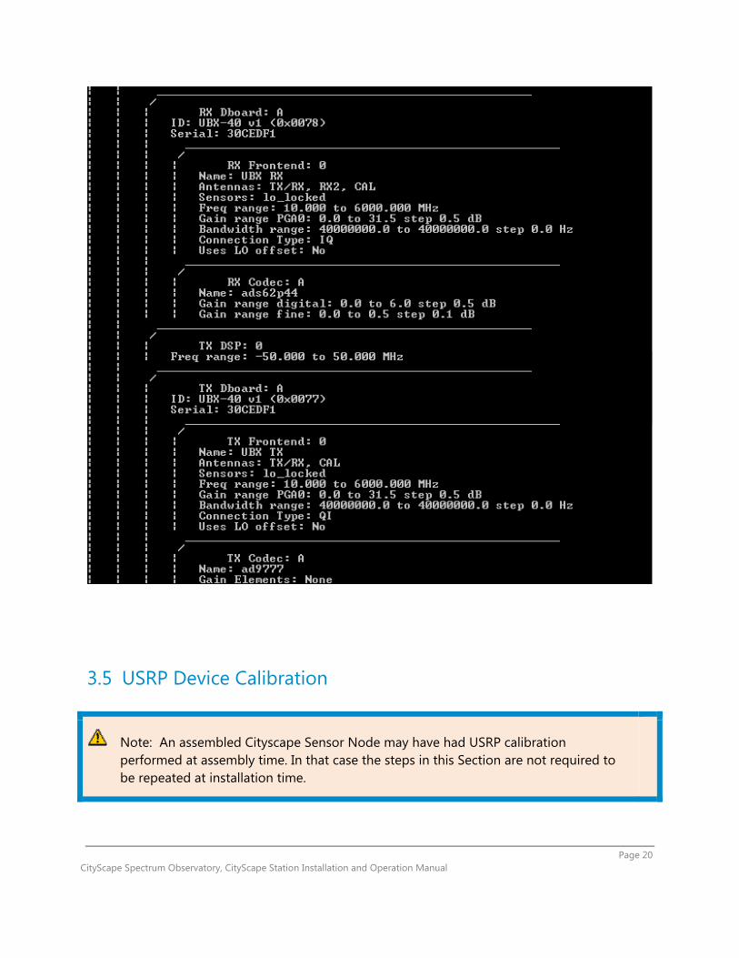
<install-path>\bin\uhd_usrp_probe.exe
Page 20 CityScape Spectrum Observatory, CityScape Station Installation and Operation Manual
3.5 USRP Device Calibration
Note: An assembled Cityscape Sensor Node may have had USRP calibration performed at assembly time. In that case the steps in this Section are not required to be repeated at installation time.

Page 21 CityScape Spectrum Observatory, CityScape Station Installation and Operation Manual
It is recommended that the USRP N200s be calibrated once after the daughterboard (UBX) is installed in the enclosure. The self-calibration tools are part of the Ettus-provided UHD software package. For more details on self-calibration tools, refer to the Ettus site here.
The calibration tools produce data files that tabulate the characteristics of a specific UBX board. These files are stored on the host PC, with names keyed to the UBX serial number. Each time the Scanner service starts, it reads the stored data through its UHD library and uses it to adjust the received data from the USRP.
3.5.1 UHD Calibration (I-Q Imbalance Correction)
3.5.1.1 Determining whether UHD calibration files are installed
Open a command window with administrative privileges. This can be PowerShell, or a Command Prompt window opened by “Run as Administrator”.
Enter the following commands:
cd %windir%\system32\config\systemprofile\AppData\Roaming
dir .uhd\cal
If the calibration files are installed, then the directory will exist and will contain three “.csv” files with your UBX board’s serial number as part of their filenames. If the directory does not exist or is empty, the calibration files have not been installed.
If the directory does not exist, create it now with this command:
mkdir .uhd .uhd\cal
3.5.1.2 Generating and installing the UHD calibration files
The following commands will require exclusive access to the USRP. If the Scanner service (in section #4 below) is already installed and running, stop it (via Control Panel / Administrative Tools / Services) before continuing with this section. From a command window with administrative privileges, enter the following commands:
Page 22 CityScape Spectrum Observatory, CityScape Station Installation and Operation Manual
cd %UHD_PKG_PATH%\bin
set UHD_CONFIG_DIR=%windir%\system32\config\systemprofile\AppData\Roaming\.uhd\cal
uhd_cal_rx_iq_balance.exe --verbose --args arg=192.168.10.2
uhd_cal_tx_iq_balance.exe --verbose --args arg=192.168.10.2
uhd_cal_tx_dc_offset.exe --verbose --args arg=192.168.10.2
Each of the three “uhd_cal” commands will take a few minutes to run, sending some diagnostic output to the console. You do not need to record or act upon this console output; enabling it (by the --verbose argument) merely to allows you to confirm that the command is running. After the above commands have been run, check again (as in Section 3.5.1.1) to verify that the calibration files are now in place.
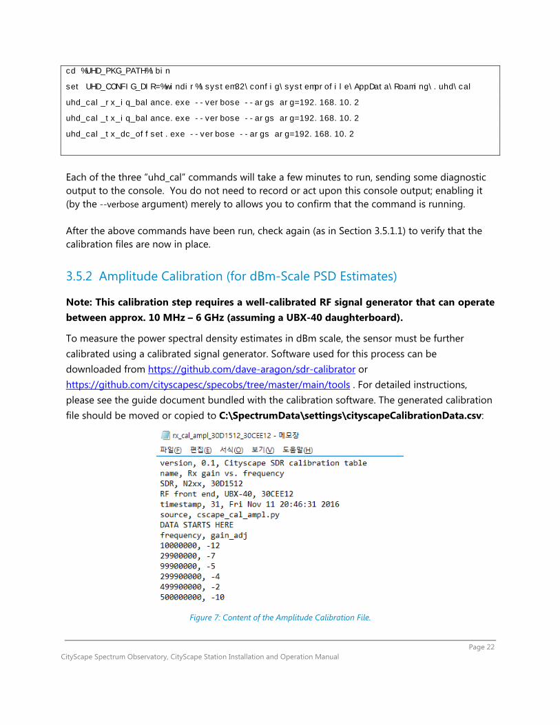
3.5.2 Amplitude Calibration (for dBm-Scale PSD Estimates)
Note: This calibration step requires a well-calibrated RF signal generator that can operate between approx. 10 MHz – 6 GHz (assuming a UBX-40 daughterboard).
To measure the power spectral density estimates in dBm scale, the sensor must be further calibrated using a calibrated signal generator. Software used for this process can be downloaded from https://github.com/dave-aragon/sdr-calibrator or https://github.com/cityscapesc/specobs/tree/master/main/tools . For detailed instructions, please see the guide document bundled with the calibration software. The generated calibration file should be moved or copied to C:\SpectrumData\settings\cityscapeCalibrationData.csv:
Figure 7: Content of the Amplitude Calibration File.
Page 23 CityScape Spectrum Observatory, CityScape Station Installation and Operation Manual
4 Spectrum Observatory Software Installation
Once you have received your approval e-mail, please download the Spectrum Observatory measurement station software from http://cityscape.cloudapp.net/ under the Register Station link. In order to see the link, you’ll be required to sign in.
When you receive an assembled Cityscape Sensor Node, these system software installations will already have been performed. This manual section is informational and refers to the default, pre-installed system software set. Variations are possible, but step by step instructions are not available in those cases. The only officially supported system software set is the one supplied by Shared Spectrum Corporation.
Note: It is assumed that Sections 2 and 3 are complete. At this point, an antenna is installed and wired to the USRP, the USRP is physically connected to the host PC and the necessary network interfaces have been established. If this is not the case, please complete those steps first.
4.1 Remove Old Versions, Check Prerequisites
Below are the software prerequisites that must be installed on the machine before using the import service. In particular:
Remove old spectrum observatory software o If you are upgrading a Spectrum Observatory measurement station from a previous
release, please complete the below two steps: 1. Uninstall “Microsoft Spectrum Observatory” (or “CityScape Spectrum
Observatory”) software from the host PC. This will stop and remove all the software that was installed earlier.
2. Post uninstallation, delete the C:\SpectrumData folder. (The uninstaller will not automatically remove this folder.)
Visual C++ Redistributable 2013 o The Visual Studio 2013 redistributable is required to run the Spectrum Observatory
measurement station software on the host PC. Download the software from here: http://www.microsoft.com/en-us/download/details.aspx?id=40784
Page 24 CityScape Spectrum Observatory, CityScape Station Installation and Operation Manual
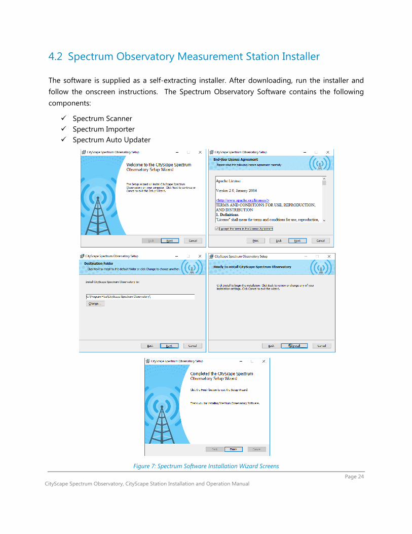
4.2 Spectrum Observatory Measurement Station Installer
The software is supplied as a self-extracting installer. After downloading, run the installer and follow the onscreen instructions. The Spectrum Observatory Software contains the following components:
Spectrum Scanner Spectrum Importer Spectrum Auto Updater
Figure 7: Spectrum Software Installation Wizard Screens

Page 25 CityScape Spectrum Observatory, CityScape Station Installation and Operation Manual
4.3 Spectrum Data Folder Structure Explained
You may notice that folders are created under C:\SpectrumData. Each folder has a role corresponding to a processing step of the Spectrum Observatory Software, as follows:
Figure 8: Spectrum Data Folders
Autoupdate: If there is an updated version of the Spectrum installer available, auto updater service detects and downloads the MSI file here. It will then install and updates the software automatically.
Errors: For any errors when processing a file for upload, an error is logged in the event viewer and the file is moved to this directory
Scan: All spectrum scan data is captured in this folder. A new file is created for each scan file frequency set for the spectrum station.
Settings: Settings will contain all the scan configuration for RF sensors. Settings will be downloaded once the importer service is started. The settings file contains the values entered for the station registration from spectrum observator50y portal.
Logging: If logging enabled in the scanner configuration file, all logging will be stored initially in the scan directory and uploaded to the Azure blob. One logging file will be created for each scan data file raw IQ data (.dsor) and the scan data (.dsox).
Figure 9: Spectrum Software Install Location
Page 26 CityScape Spectrum Observatory, CityScape Station Installation and Operation Manual
Scanner: Scanner runs as a Windows service, reading captured spectrum data from the USRP and formatting it into files. Scanner operation is governed by a config file, which contains settings obtained from the Cityscape portal (web server).
Importer: Importer runs as a Windows service and looks for the pending files (RF scan data) to be processed. Data is imported from these files and uploaded to the Windows Azure cloud. Importer requires a valid Measurement Station Access ID so that the data goes into correct location on the cloud. (Please see Section 5.2, Importer Configuration, for how to update the Measurement Station Access ID.)
Importer by default looks for the files under %WINDOWSROOT%\SpectrumData\scan folder. Importer service is not automatically started after installation. It requires user to restart the service manually once the setup is complete.
Auto Updater: This Windows service runs in the background, checking for any updates to the Spectrum Observatory Software. If a newer version is released, Auto Updater obtains the installer package from the Cityscape portal and updates the software on the Sensor Node. This helps to keep the software versions current and consistent across all the measurement stations.

Page 27 CityScape Spectrum Observatory, CityScape Station Installation and Operation Manual
5 Registering the Station
5.1 Making Your Station Known to the Observatory Server
When the measurement station setup (Host PC Configuration and Device Setup) is complete, you can register the measurement station with the CityScape Spectrum Observatory site. This is a required step and you will need to sign-in using a Microsoft account in order to register the station. Go to http://cityscape.cloudapp.net/ , click sign-in button (located at left menu bar) to log in to your Microsoft account. Once logged in, click “Station Registration” button to register your station.
Figure 10: “Register Station” Button on the Left Menu Bar
The station registration form is a wizard type - fill in details for the station and then submit for approval. For details on the values to be provided, please see the section 7 “RF Sensor Knobs Explained”.
When you click on submit button, you’ll be presented with a station access ID. Please copy this ID down – you will need it for the following step.
Page 28 CityScape Spectrum Observatory, CityScape Station Installation and Operation Manual
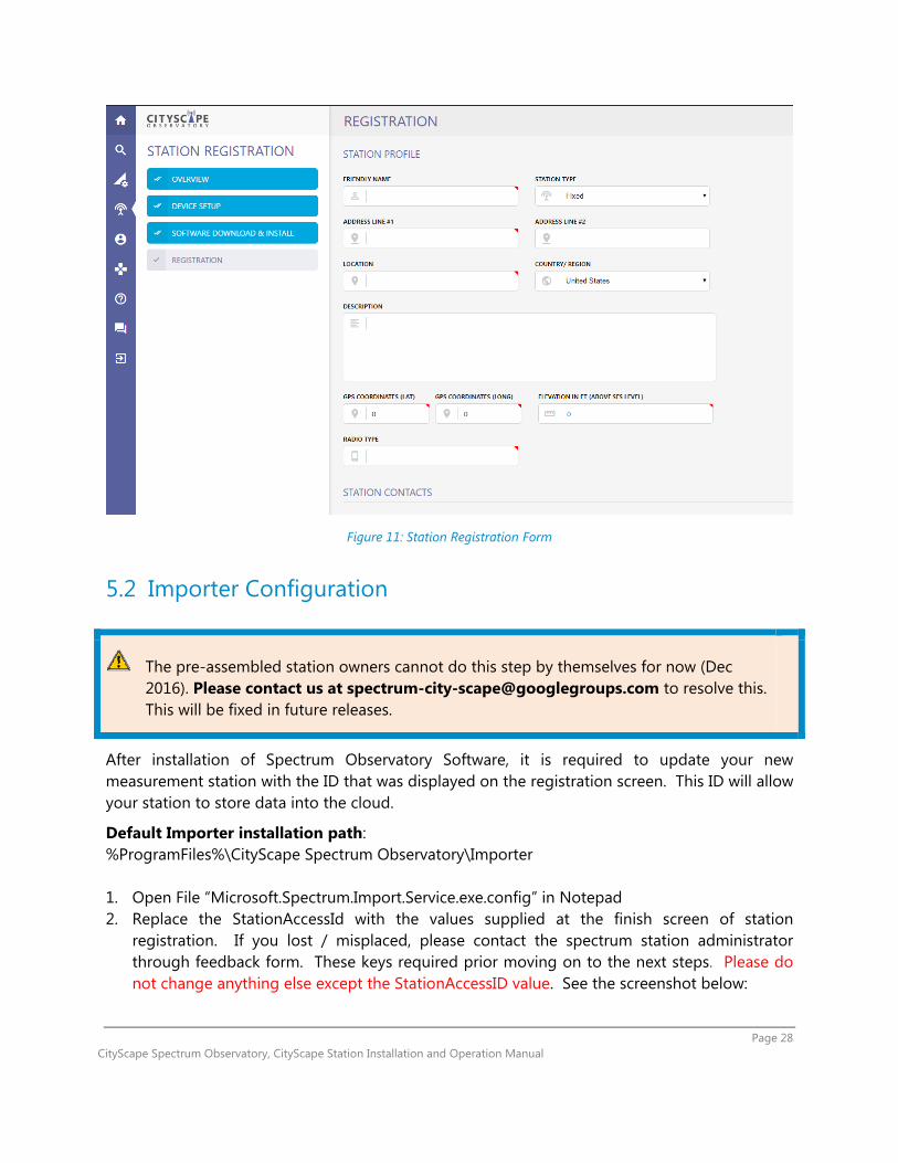
Figure 11: Station Registration Form
5.2 Importer Configuration
The pre-assembled station owners cannot do this step by themselves for now (Dec 2016). Please contact us at [email protected] to resolve this. This will be fixed in future releases.
After installation of Spectrum Observatory Software, it is required to update your new measurement station with the ID that was displayed on the registration screen. This ID will allow your station to store data into the cloud.
Default Importer installation path: %ProgramFiles%\CityScape Spectrum Observatory\Importer 1. Open File “Microsoft.Spectrum.Import.Service.exe.config” in Notepad 2. Replace the StationAccessId with the values supplied at the finish screen of station
registration. If you lost / misplaced, please contact the spectrum station administrator through feedback form. These keys required prior moving on to the next steps. Please do not change anything else except the StationAccessID value. See the screenshot below:

Page 29 CityScape Spectrum Observatory, CityScape Station Installation and Operation Manual
3. Save the config file changes (you may have to allow the write access to Importer folder as it
is protected). 4. Now start the “CityScape Spectrum Observatory Importer” service. You can do this starting
the Windows Services (services.msc from command prompt): 5. From the services list, start the CityScape Spectrum Importer Service as show below:

Page 30 CityScape Spectrum Observatory, CityScape Station Installation and Operation Manual
6 Verify Station Installation & Registration
6.1 Checking Service Status
Open a command prompt and type services.msc Look for the three services below, all of them should in Running state
Open Windows Explorer and locate the scan folder. You should see at least one file being written by the Scanner (with the current date and hour stamp) .dsox – is the scan file that the data is being stored .dsor – is the raw IQ file from the device .dsol – contains logging information for each of the scan file being captured (for example .dsox and .dsor)
Data gets uploaded instantly to Windows Azure for further processing. The processed data should be available within few minutes.
To make sure that the data files are being uploaded to the cloud correctly, please visit the web portal and try plotting or downloading data files by following Section 7.2 of this document after a few hours (the server may take time to process the received data, so the received data may not show up immedately).
Page 31 CityScape Spectrum Observatory, CityScape Station Installation and Operation Manual
7 Station Operation
7.1 RF Sensor Knobs Explained
One of the distinctive features of CityScape is the flexible sensor configuration allowed to end-user for the scan and I-Q data collection. In this section, we explain the “knobs” (or user-accessible settings) of the RF sensor station as they are presented via the web interface. Once submitted through the Cityscape portal, the settings are pushed to the Sensor Node where they will configure (or re-configure) the scanning process. The settings will govern all subsequent data collected by the Sensor Node and pushed to Azure cloud storage, until you decide to change the settings again.
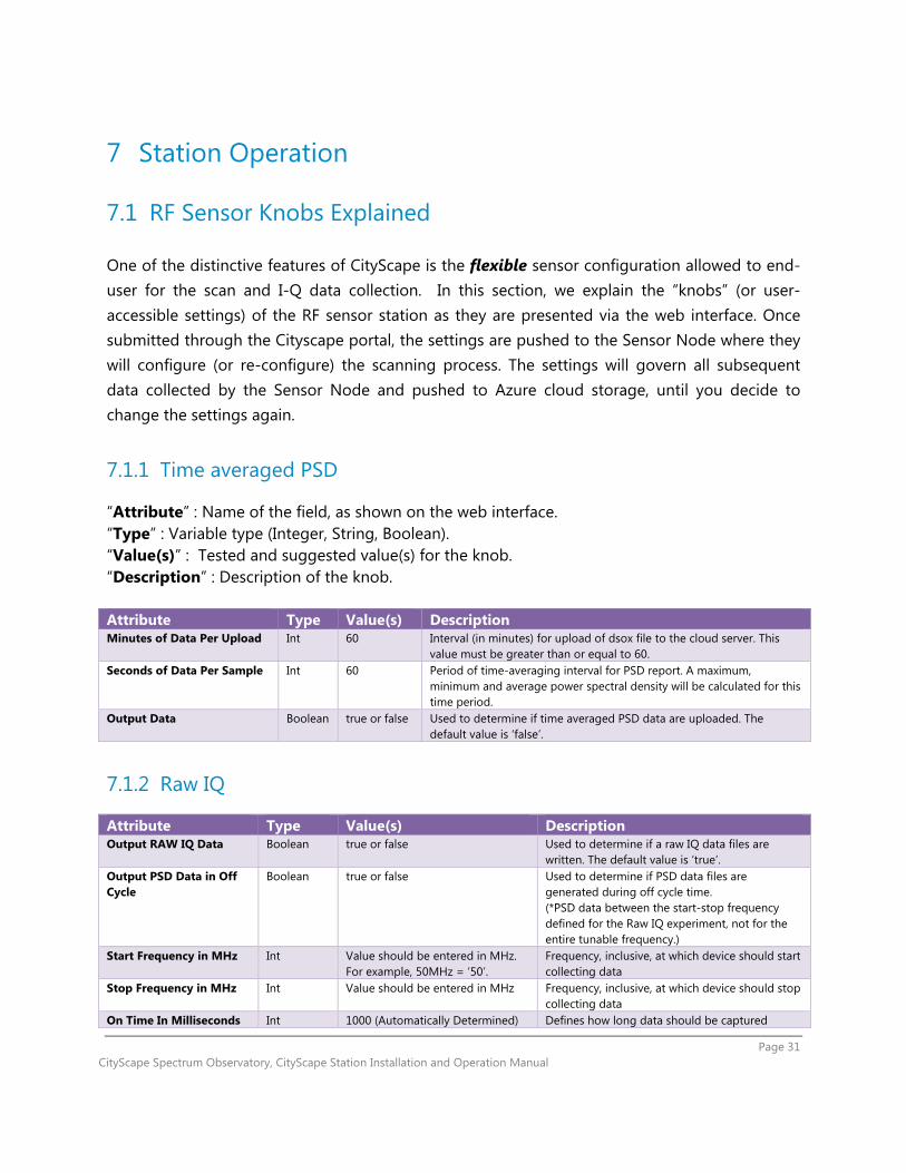
7.1.1 Time averaged PSD
“Attribute” : Name of the field, as shown on the web interface. “Type” : Variable type (Integer, String, Boolean). “Value(s)” : Tested and suggested value(s) for the knob. “Description” : Description of the knob. Attribute Type Value(s) Description Minutes of Data Per Upload Int 60 Interval (in minutes) for upload of dsox file to the cloud server. This
value must be greater than or equal to 60. Seconds of Data Per Sample Int 60 Period of time-averaging interval for PSD report. A maximum,
minimum and average power spectral density will be calculated for this time period.
Output Data Boolean true or false Used to determine if time averaged PSD data are uploaded. The default value is ‘false’.
7.1.2 Raw IQ
Attribute Type Value(s) Description Output RAW IQ Data Boolean true or false Used to determine if a raw IQ data files are
written. The default value is ‘true’. Output PSD Data in Off Cycle
Boolean true or false Used to determine if PSD data files are generated during off cycle time. (*PSD data between the start-stop frequency defined for the Raw IQ experiment, not for the entire tunable frequency.)
Start Frequency in MHz Int Value should be entered in MHz. For example, 50MHz = ‘50’.
Frequency, inclusive, at which device should start collecting data
Stop Frequency in MHz Int Value should be entered in MHz Frequency, inclusive, at which device should stop collecting data
On Time In Milliseconds Int 1000 (Automatically Determined) Defines how long data should be captured

Page 32 CityScape Spectrum Observatory, CityScape Station Installation and Operation Manual
within a cycle. Duty Cycle In Milliseconds
Int 60000 (Automatically Determined) Defines the length of the cycle duration.
File Duration in Seconds Int 60 – for 1 mins of data in each file (Automatically Determined)
Seconds of data written to a file before creating another one.
Retention Seconds Int 3600 – for 1 hour (Automatically Determined)
Duration that a Raw IQ data file (.dsor) can be retained on the host PC (time to live) *, IF it has not been uploaded by uploader
7.1.3 Scanner Configuration
It is required to have a separate section for each device under “Devices”. By default in the scanner configuration file, you’ll notice four sections added. One each for RF Explorer, USRP B200, USRP N200 SBX and USRP N200 WBX. For each device values vary for few of the elements. The CityScape stations are based on a USRP N200 and a UBX daughterboard, and is not listed in there, but this can be simply typed in.
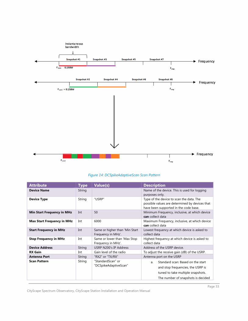
There are two different scan modes for collecting power spectral density: “StandardScan” and “DCSpikeAdaptiveScan”. DCSpikeAdaptiveScan tries to remove DC spikes observed from the PSD data obtained and calculated from homodyne receivers (like USRP), as well as aliasing effects due to the filter imperfection. StandardScan does not do this. Note that, due to the design of the scanner software, this may also affect the I-Q data collection order.
Figure 13: StandardScan Scan Pattern
Figure 12: Meaning of "Retention Seconds" Setting
Page 33 CityScape Spectrum Observatory, CityScape Station Installation and Operation Manual
Figure 14: DCSpikeAdaptiveScan Scan Pattern
Attribute Type Value(s) Description Device Name String Name of the device. This is used for logging
purposes only. Device Type String “USRP” Type of the device to scan the data. The
possible values are determined by devices that have been supported in the code base.
Min Start Frequency in MHz Int 50 Minimum Frequency, inclusive, at which device can collect data
Max Start Frequency in MHz Int 6000 Maximum Frequency, inclusive, at which device can collect data
Start Frequency in MHz Int Same or higher than ‘Min Start Frequency in MHz’.
Lowest frequency at which device is asked to collect data
Stop Frequency in MHz Int Same or lower than ‘Max Stop Frequency in MHz’.
Highest frequency at which device is asked to collect data
Device Address String USRP N200’s IP Address Address of the USRP device. RX Gain Int Gain level of the radio To adjust the receive gain (dB) of the USRP. Antenna Port String “RX2” or “TX/RX” Antenna port on the USRP Scan Pattern String “StandardScan” or
“DCSpikeAdaptiveScan” a. Standard scan: Based on the start
and stop frequencies, the USRP is
tuned to take multiple snapshots.
The number of snapshots is decided
Page 34 CityScape Spectrum Observatory, CityScape Station Installation and Operation Manual
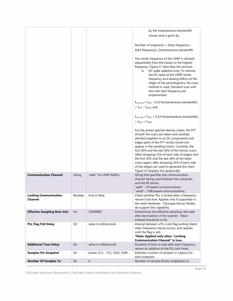
by the instantaneous bandwidth
chosen and is given by
Number of snapshots = (Stop frequency – Start frequency) / Instantaneous bandwidth
The center frequency of the USRP is retuned sequentially from the lowest to the highest frequency. Figure 17 describes this process.
b. DC spike adaptive scan: To remove the DC spike at the USRP center frequency and aliasing effects at the edges of the periodograms, this scan method is used. Standard scan with two new start frequency are implemented:
fnew start = fstart - 0.15*(Instantaneous bandwidth)
= fstart - foffset, and
fnew start = fstart + 0.15*(Instantaneous bandwidth) = fstart + foffset
For the power spectral density charts, the FFT of both the scans are taken and carefully stitched together so as DC components and edges parts of the FFT results would not appear in the resulting charts. Currently, the first 30% and the last 20% of the former scans (after dropping 15% of each side of edges) and the first 20% and the last 30% of the latter scans (again, after dropping 15% of each side of the edges) are used to generate the chart. Figure 14 displays this graphically.
Communication Channel String “addr” for USRP N200’s String that specifies the communication channel being used between the computer and the RF sensor. “addr” – IP based communications “serial” – USB based communications
Locking Communication Channel
Boolean true or false. Check whether PLL is locked after a frequency retune if set true. Applies only if supported in the radio hardware. Cityscape Sensor Nodes do support this capability.
Effective Sampling Rate (Hz) Int 25000000 Dertermines the effective sampling rate (rate after decimation) of the scanner. Value entered should be in Hz.
PLL Flag Poll Delay Int value in milliseconds Interval between a PLL Lock flag polling (starts when frequency retune occurs, and repeats until the flag is set). *Note: Applied only when “Locking Communication Channel” is true..
Additional Tune Delay Int value in milliseconds Duration of time to wait after each frequency retune (in addition to the PLL lock time).
Samples Per Snapshot Int power of 2; - 512, 1024, 2048 … Indicates number of samples to capture for each snapshot.
Number Of Samples To Int 0 Number of sample blocks (snapshots) to

Page 35 CityScape Spectrum Observatory, CityScape Station Installation and Operation Manual
Throw Away discard after tuning the RF Sensor Number of Snapshots per Channel Visit
Int 1 Number of sample blocks (snapshots) to receive before retuning the RF sensor.
GPS Enabled Boolean true or false Include GPS data in the scan files and the raw IQ data files, only if the USRP device supports GPS. The Cityscape Pilot USRPs do not have GPS receivers.
7.1.4 Recommended Settings for the Cityscape Sensor Node
The interface allows far more combinations of knob settings than can be thoroughly tested. The settings given below have been validated by the Cityscape team and are a good starting point.
Attribute Type Value(s)
Device Name String <Any Name> Limit to 64 characters or less
Device Type String USRP
Start Frequency in MHz Int 50 (UBX)
Stop Frequency in MHz Int 6000 (UBX)
Device Address String 192.168.10.2
RX Gain Int 10
Antenna Port String RX2
Scan Pattern String StandardScan for I/Q data collection; DCAdaptiveSpikeScan for PSD data collection.
Communication Channel String addr
Locking Communication Channel Boolean true
Effective Sampling Rate Int 25000000
PLL Flag Poll Delay Int 0
Add. Tune Delay Int 60
Samples Per Snapshot Int 1024
Number Of Sample To Throw Away Int 0
Number of snapshots per channel visit Int 1
GPS Enabled Boolean false
Page 36 CityScape Spectrum Observatory, CityScape Station Installation and Operation Manual
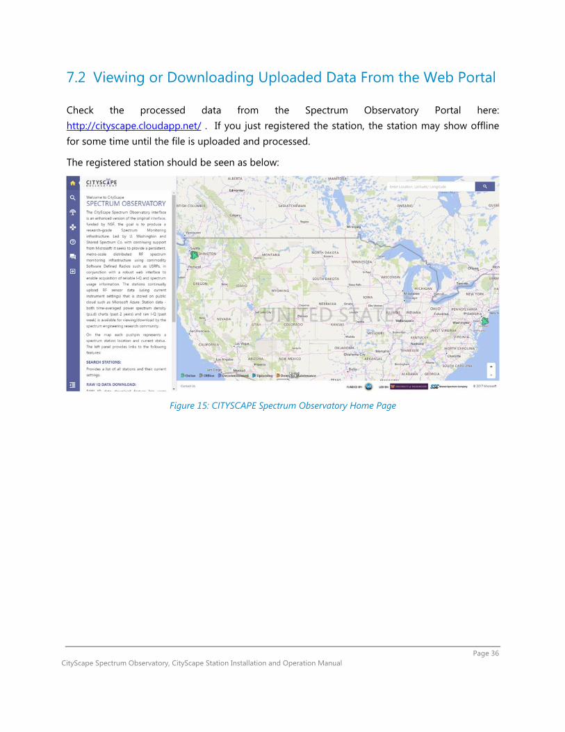
7.2 Viewing or Downloading Uploaded Data From the Web Portal
Check the processed data from the Spectrum Observatory Portal here: http://cityscape.cloudapp.net/ . If you just registered the station, the station may show offline for some time until the file is uploaded and processed.
The registered station should be seen as below:
Figure 15: CITYSCAPE Spectrum Observatory Home Page

Page 37 CityScape Spectrum Observatory, CityScape Station Installation and Operation Manual
Click the satellite icon on the map (to view an individual station) or the magnifier icon at the left top coner (to view a list of registered stations) to see details about the stations.
Figure 16: CityScape Station List Example
Now, click the name of the station (shown on the left pane or overlayed on the map) to go into the station information page.
Figure 17: Name of the Station.
Page 38 CityScape Spectrum Observatory, CityScape Station Installation and Operation Manual
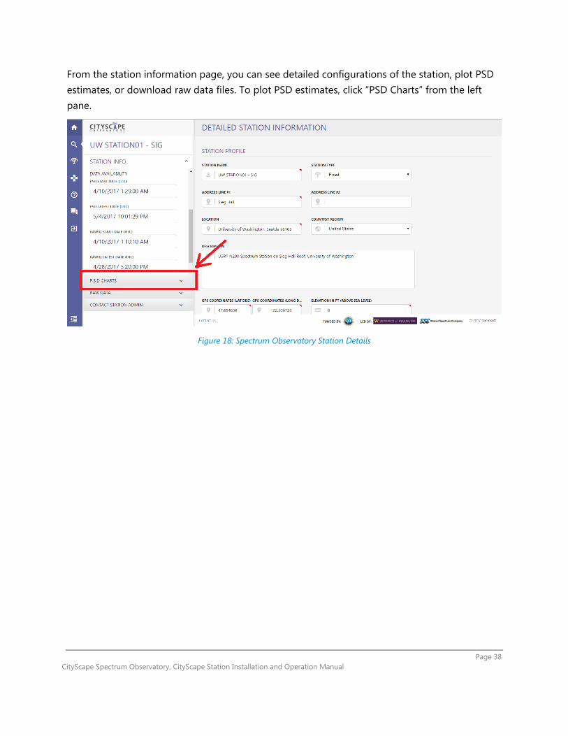
From the station information page, you can see detailed configurations of the station, plot PSD estimates, or download raw data files. To plot PSD estimates, click “PSD Charts” from the left pane.
Figure 18: Spectrum Observatory Station Details

Page 39 CityScape Spectrum Observatory, CityScape Station Installation and Operation Manual
You have to input the range of the frequency and the date to the left pane to generate and display the PSD estimate chart. You will see something like the figure below if everything is done correctly.
(* The Y-axis of the plots is fixed to “dBm/FFT Bin size”(calibrated), or “dB/Hz”(uncliabrated). For now, you will have to download and re-normalize the PSD estimate files if different units are needed.)
Figure 19: Power Spectral Density Chart
Same goes with the raw data download: simply click the “Raw Data” menu from the left pane, instead of “P.S.D Charts”, and input the date range and the type of the raw data (PSD estimates or Raw I-Q data files). You will see file download links on the right pane if there are matching data files.

Page 40 CityScape Spectrum Observatory, CityScape Station Installation and Operation Manual
Figure 20: Raw Data Download
Note: After the station is registered and files are getting uploaded to the cloud, it will take approximately an hour to process all aggregates and make the charts available. From the station information section, you can see the data availability date and time.
7.3 Parsing Raw Data Files
Raw I-Q and PSD data downloadable from the CityScape web portal are stored in Google’s Protocol Buffer (‘Protobuf’) data structure and compressed using System.IO.Compression class in Microsoft .NET framework. To parse the data, users need to decompress the file and then use a Protobuf parser software.
7.3.1 Using CityScape Project Source
Users can develop their own parser from the source code of the CityScape Station project (in C#). Source codes are available at https://github.com/cityscapesc/specobs .
Page 41 CityScape Spectrum Observatory, CityScape Station Installation and Operation Manual
7.3.2 Using Python
Alternatively, users can directly use or modify sample Python-based parser scripts downloadable at https://github.com/cityscapesc/specobs/tree/master/main/tools . Please refer to the quick start guide provided with the parser software.
7.4 Troubleshooting
If you have any questions or issues which are not covered in this document, the release note, and the web portal, please contact the project group email [email protected].
7.4.1 Station Not Generating or Uploading Data (Gray Station Icon)
If you are a third party user, please contact the station administrator to get the problem resolved.
7.4.1.1 New Station
If your station is a pre-assembled unit shipped from Shared Spectrum Company and if you don’t have necessary credentials to access the desktop interface of the host PC, please contact Shared Spectrum Company to get the problem resolved. If not, please follow the checklist below.
* The checklist assumes that you can either remotely (using TeamViewer or similar alternatives) or locally access the desktop of the sensor’s host PC.
Try matching knob settings to the recommended settings (Sec 7.1.4), if they are configured differently.
Make sure that your sation access key is set correctly (See Section 5.2). From Windows’s “Task Manager”, check if “SpectrumScannerService”,
“SpectrumImportService”, and “SpectrumAutoUpdaterService” services are running (they should be).
o Try re-starting these services. Open a command prompt and use “taskkill /F” command to kill the services if they hang and do not restart nicely.
Launch Windows’s “Event Viewer” application, expand “Windows Logs” section and then click “Application” subsection to view event logs. If you see error messages from SpectrumImportService or SpectrumScannerSerivce, please try correcting them.

Page 42 CityScape Spectrum Observatory, CityScape Station Installation and Operation Manual
o If you are not sure what the error message means, contact the group e-mail [email protected] for a help.
Check whether the USRPs are correctly detected by the PC, by following Section 3.4. Temporarily remove calibration files (from Section 3.5) and try re-starting the services.
(Do this if and only if your station is not a pre-built unit from SSC. Place back the calibration files to the right positions once you are done.)
Try re-booting the station. Check the network connectivity and firewall settings.
7.4.1.2 Previously Working Station
If your station is a pre-assembled unit shipped from Shared Spectrum Company and if you don’t have necessary credentials to access the desktop interface of the host PC, please try unplugging and re-plugging in the external power cable and the Ethernet cable. Also, check if the Ethernet connection provides a stable Internet connection to the station and has a valid DHCP server which assigns a proper IP address to connected machines. If the station still does not work, contact Shared Spectrum Company to get the problem resolved. If not, please follow the checklist below.
* The checklist assumes that you can either remotely (using TeamViewer or similar alternatives) or locally access the desktop of the sensor’s host PC.
Try matching knob settings to the recommended settings (Sec 7.1.4), if they are configured differently.
From Windows’s “Task Manager”, check if “SpectrumScannerService”, “SpectrumImportService”, and “SpectrumAutoUpdaterService” services are running (they should be).
o Try re-starting these services. Open a command prompt and use “taskkill /F” command to kill the services if they hang and do not restart nicely.
Launch Windows’s “Event Viewer” application, expand “Windows Logs” section and then click “Application” subsection to view event logs. If you see error messages from SpectrumImportService or SpectrumScannerSerivce, please try correcting them.
o If you are not sure what the error message means, contact the group e-mail [email protected] for a help.
Check whether the USRPs are correctly detected by the PC, by following Section 3.4. Try re-booting the station. Check the network connectivity.

Page 43 CityScape Spectrum Observatory, CityScape Station Installation and Operation Manual
7.4.2 Uploaded Data (PSD, etc) Does Not Look Right.
Verify your assumptions first – maybe the the station is working correctly after all. o Check if your data quality issue is listed on the release note as a known issue.
Try reducing the RX gain level knob or re-positioning the antennas, if circuit overload is suspected.
Try reverting back the knob settings to the recommended settings (Sec 7.1.4), if they are different.
If you assembled your own sensors, try replacing the Ethernet cards and the Etherenet cables which are used to communicate with USRPs (faulty Ethernet connection may cause data loss).
If you assembled your own sensors, make sure that the antenna port that you are using matches the antenna port that you configured from the web portal. You may have to open up your USRP to check this (RF1/RF2 marking on the housing of the USRPs may not match with the internal wirings).
If you assembled your own sensors, try temporarily removing calibration files (from Section 3.5) and re-starting the scan services.
7.4.3 Station Access Key is Lost
Please contact the project group email [email protected].
7.5 Contributions
For general feedbacks, you can use the project group email [email protected] or the feedback page available from the official web portal. If you want to actually access and modify the project source codes, please check the “Contributions” pages available in the web portal or see the section 7.5.1 below.
7.5.1 Project Repository
The source codes of the CityScape project are available at: https://github.com/cityscapesc/specobs .


![CityScape: A Metro-area Spectrum Observatory · Centralized spectrum monitoring systems were implemented in [4] and [5] to enable spectrum sharing. In this work, we report on a newly](https://img.dokumen.tips/doc/110x75/604b4563ee222773fe68cb42/cityscape-a-metro-area-spectrum-observatory-centralized-spectrum-monitoring-systems.jpg)