Embed Size (px)
Citation preview
Cisco Virtual Wireless Controller Deployment Guide, Release 7.5
Last Updated: January, 2018
Contents• Introduction
• Prerequisites
• Deploying Virtual WLC on UCS-E Modules for ISR-G2
– Loading ISR-G2 Image
– Download the Customized VMWare Hypervisor Image for UCS-E
– VMWare Hypervisor Image Installation on UCS-E Module
– Installation with KVM Console on UCS-E Module
– Assign Network and Static IP Address to the VMWare vSphere Hypervisor
– Install Virtual Wireless Lan Controller On UCS-E Module
• Deploying Virtual WLC on SRE Service Modules 710/910 for ISR-G2
– Download the Software Package for SRE Service Module
– Extract the Software Files for SRE Service Module
– Configure the SRE Service Module Interfaces
– Start the Hypervisor Install Script for SRE Service Module
– Connecting to Hypervisor on the SRE 710/910 Service Module on ISR G2
– Install Virtual Wireless Lan Controller On SRE Service Module
• Appendix
– ISR-G2 Configuration with UCS-E Module Example
– CLI option Using UCS-E Console Access for Reference
Cisco Systems, Inc.www.cisco.com
Introduction
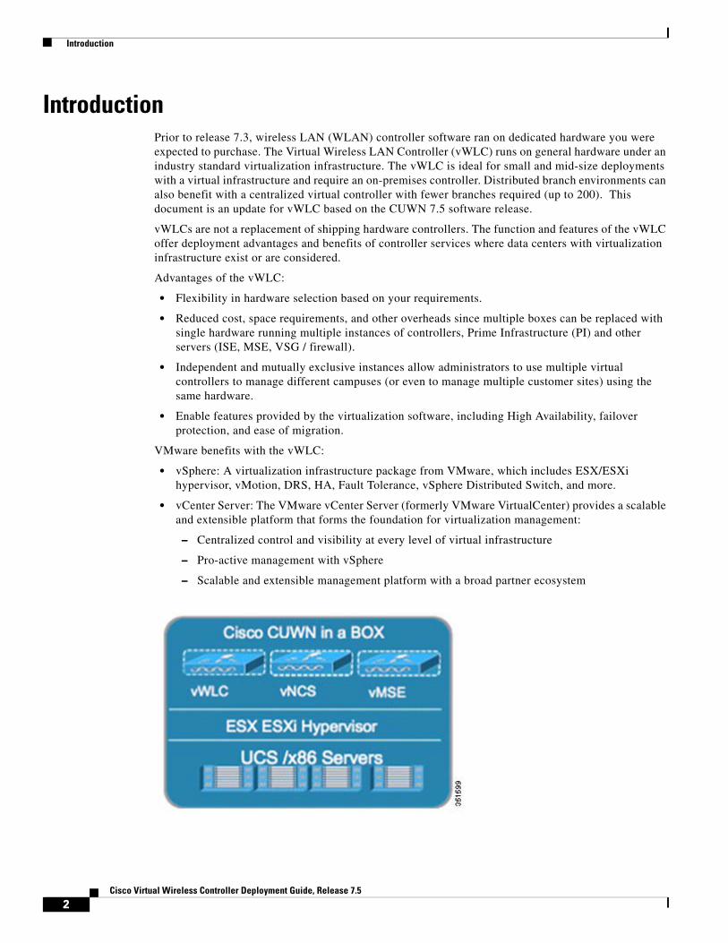
IntroductionPrior to release 7.3, wireless LAN (WLAN) controller software ran on dedicated hardware you were expected to purchase. The Virtual Wireless LAN Controller (vWLC) runs on general hardware under an industry standard virtualization infrastructure. The vWLC is ideal for small and mid-size deployments with a virtual infrastructure and require an on-premises controller. Distributed branch environments can also benefit with a centralized virtual controller with fewer branches required (up to 200). This document is an update for vWLC based on the CUWN 7.5 software release.
vWLCs are not a replacement of shipping hardware controllers. The function and features of the vWLC offer deployment advantages and benefits of controller services where data centers with virtualization infrastructure exist or are considered.
Advantages of the vWLC:
• Flexibility in hardware selection based on your requirements.
• Reduced cost, space requirements, and other overheads since multiple boxes can be replaced with single hardware running multiple instances of controllers, Prime Infrastructure (PI) and other servers (ISE, MSE, VSG / firewall).
• Independent and mutually exclusive instances allow administrators to use multiple virtual controllers to manage different campuses (or even to manage multiple customer sites) using the same hardware.
• Enable features provided by the virtualization software, including High Availability, failover protection, and ease of migration.
VMware benefits with the vWLC:
• vSphere: A virtualization infrastructure package from VMware, which includes ESX/ESXi hypervisor, vMotion, DRS, HA, Fault Tolerance, vSphere Distributed Switch, and more.
• vCenter Server: The VMware vCenter Server (formerly VMware VirtualCenter) provides a scalable and extensible platform that forms the foundation for virtualization management:
– Centralized control and visibility at every level of virtual infrastructure
– Pro-active management with vSphere
– Scalable and extensible management platform with a broad partner ecosystem
2Cisco Virtual Wireless Controller Deployment Guide, Release 7.5
Prerequisites
Prerequisites
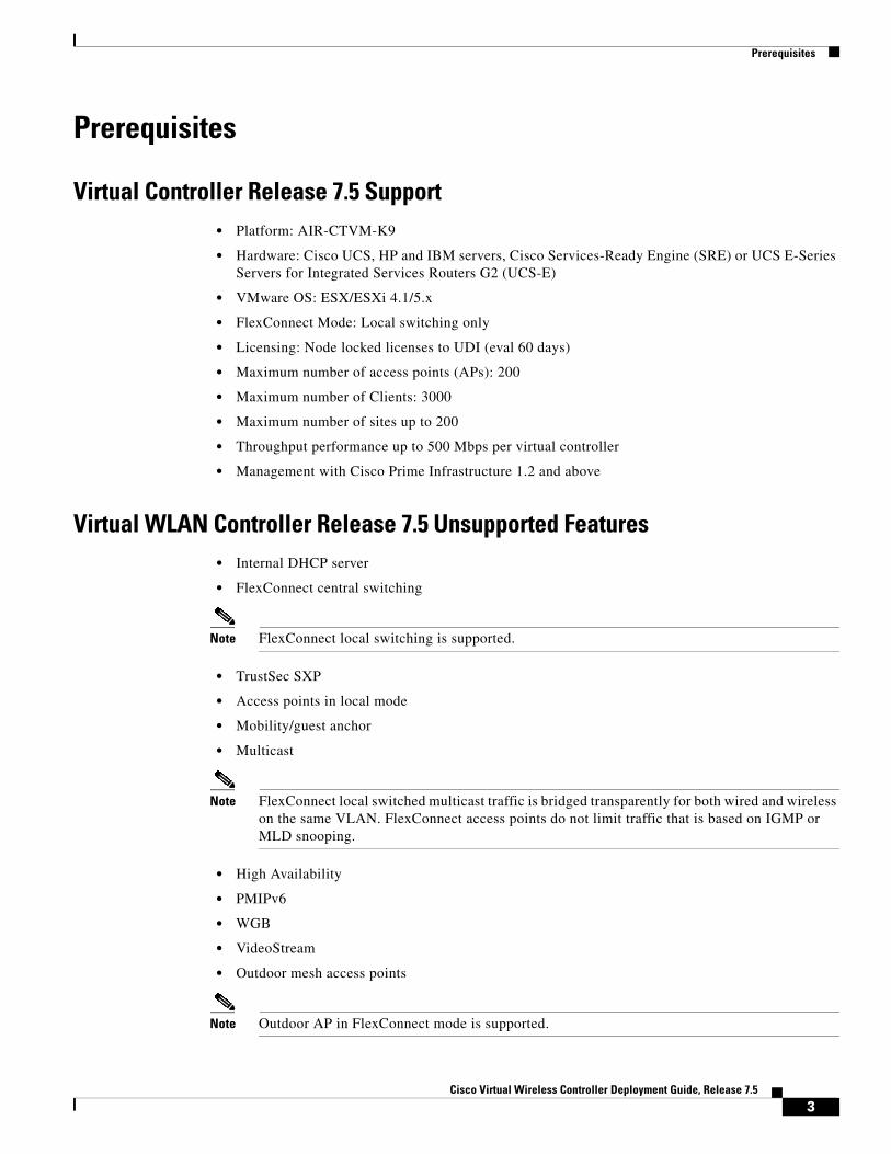
Virtual Controller Release 7.5 Support• Platform: AIR-CTVM-K9
• Hardware: Cisco UCS, HP and IBM servers, Cisco Services-Ready Engine (SRE) or UCS E-Series Servers for Integrated Services Routers G2 (UCS-E)
• VMware OS: ESX/ESXi 4.1/5.x
• FlexConnect Mode: Local switching only
• Licensing: Node locked licenses to UDI (eval 60 days)
• Maximum number of access points (APs): 200
• Maximum number of Clients: 3000
• Maximum number of sites up to 200
• Throughput performance up to 500 Mbps per virtual controller
• Management with Cisco Prime Infrastructure 1.2 and above
Virtual WLAN Controller Release 7.5 Unsupported Features• Internal DHCP server
• FlexConnect central switching
Note FlexConnect local switching is supported.
• TrustSec SXP
• Access points in local mode
• Mobility/guest anchor
• Multicast
Note FlexConnect local switched multicast traffic is bridged transparently for both wired and wireless on the same VLAN. FlexConnect access points do not limit traffic that is based on IGMP or MLD snooping.
• High Availability
• PMIPv6
• WGB
• VideoStream
• Outdoor mesh access points
Note Outdoor AP in FlexConnect mode is supported.
3Cisco Virtual Wireless Controller Deployment Guide, Release 7.5
Prerequisites
• Indoor mesh access points
• Application Visibility and Control (AVC)
• Client downstream rate limiting for central switching
LimitationsWhen multiple VM instances are rebooted simultaneously from the system, it is possible that access points may disconnect from the network even if the primary vWLC instance is active. This is a VMware limitation and not a product issue of vWLC.
Virtual WLAN Controller Release 7.5 Enhancements• Data DTLS
• AP Enforced Rate Limiting
• Additional FlexConnect Enhancements (see release notes for more information.)
Single Virtual Controller Resource Requirement• CPU: 1 virtual CPU
• Memory: 2 GB
• Disk Space: 8 GB
• Network Interfaces: 2 virtual Network Interface cards (vNICs)
Suggested Hardware Recommendations for Hosting Cisco Virtual Controllers• UCS R210-2121605W Rack Mount Server (2 RU):
– 2 * Intel Xeon CPU X5670 @ 2.93 GHz
– 16 G memory
• BM x3550 M3 Server:
– 2 * Intel Xeon 5600 series processors with 4 cores each and each core capable of doing hyper threading which gives you 16 CPUs in total @3.6 GHz
– 12G memory
• ISR G2 Services Ready Engine (SRE) :
– SRE 700/710: Single Core Intel Core Duo 1.86 GHz with 4 GB memory
– SRE 900/910: Dual Core Intel Core Duo 1.86 GHz with 4 GB memory (upgradable to 8 GB)
• UCS E-Series Servers
– UCS E140/160 Single and Double-Wide Blade: 4-6 Cores with up to 48 GB memory.
4Cisco Virtual Wireless Controller Deployment Guide, Release 7.5

Prerequisites
AP Requirement• All 802.11n APs with required software version 7.5 and above are supported.
• APs will be operating in FlexConnect mode only.
• AP autoconvert to FlexConnect is supported on controller.
• New APs ordered will ship with minimum 7.5 software from manufacturing.
• Existing APs must be upgraded to 7.5 software before joining a virtual controller.
• For Cisco 600 Series OEAP to associate with Cisco Virtual Wireless LAN Controller, follow these steps:
1. Configure the OEAP to associate with a physical controller that is using 7.5 or a later release and download the corresponding AP image.
2. Configure the OEAP so that the OEAP does not associate with the physical controller again; for example, you can implement an ACL in the network to block CAPWAP between the OEAP and the physical controller.
3. Configure the OEAP to associate with the Cisco Virtual Wireless LAN Controller.
Note The Virtual Controller in release 7.5 uses Self Signed Certificates (SSC) as against the Manufacturing Installed Certificates (MIC) in the traditional controller. The AP will be able to validate the SSC certificate provided by the virtual controller before joining. See AP Considerations in the following link: http://www.cisco.com/en/US/products/ps12723/products_tech_note09186a0080bd2d04.shtml#tshoot
Components UsedThe information in this document is based on these software and hardware versions:
• Cisco Catalyst Switch
• Wireless LAN Controllers Virtual Appliance
• Wireless LAN Controller 7.5 Software
• Cisco Prime Infrastructure 1.4
• 802.11n Access Points in FlexConnect Mode
• DHCP server
• DNS Server
• NTP
• Wireless Client Laptop, Smartphone, and Tablets (Apple iOS, Android, Windows, and Mac)
The information in this document was created from the devices in a specific lab environment. All of the devices used in this document started with a cleared (default) configuration. If your network is live, make sure that you understand the potential impact of any command.
5Cisco Virtual Wireless Controller Deployment Guide, Release 7.5
Deploying Virtual WLC on UCS-E Modules for ISR-G2
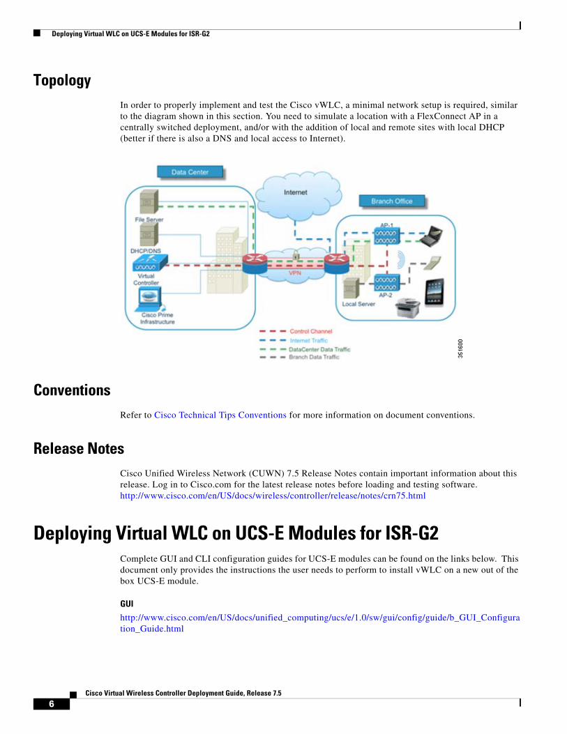
TopologyIn order to properly implement and test the Cisco vWLC, a minimal network setup is required, similar to the diagram shown in this section. You need to simulate a location with a FlexConnect AP in a centrally switched deployment, and/or with the addition of local and remote sites with local DHCP (better if there is also a DNS and local access to Internet).
ConventionsRefer to Cisco Technical Tips Conventions for more information on document conventions.
Release NotesCisco Unified Wireless Network (CUWN) 7.5 Release Notes contain important information about this release. Log in to Cisco.com for the latest release notes before loading and testing software. http://www.cisco.com/en/US/docs/wireless/controller/release/notes/crn75.html
Deploying Virtual WLC on UCS-E Modules for ISR-G2Complete GUI and CLI configuration guides for UCS-E modules can be found on the links below. This document only provides the instructions the user needs to perform to install vWLC on a new out of the box UCS-E module.
GUI
http://www.cisco.com/en/US/docs/unified_computing/ucs/e/1.0/sw/gui/config/guide/b_GUI_Configuration_Guide.html
6Cisco Virtual Wireless Controller Deployment Guide, Release 7.5
Deploying Virtual WLC on UCS-E Modules for ISR-G2
CLI
http://www.cisco.com/en/US/docs/unified_computing/ucs/e/1.0/sw/cli/config/guide/b_CLI_Configuration_Guide.html
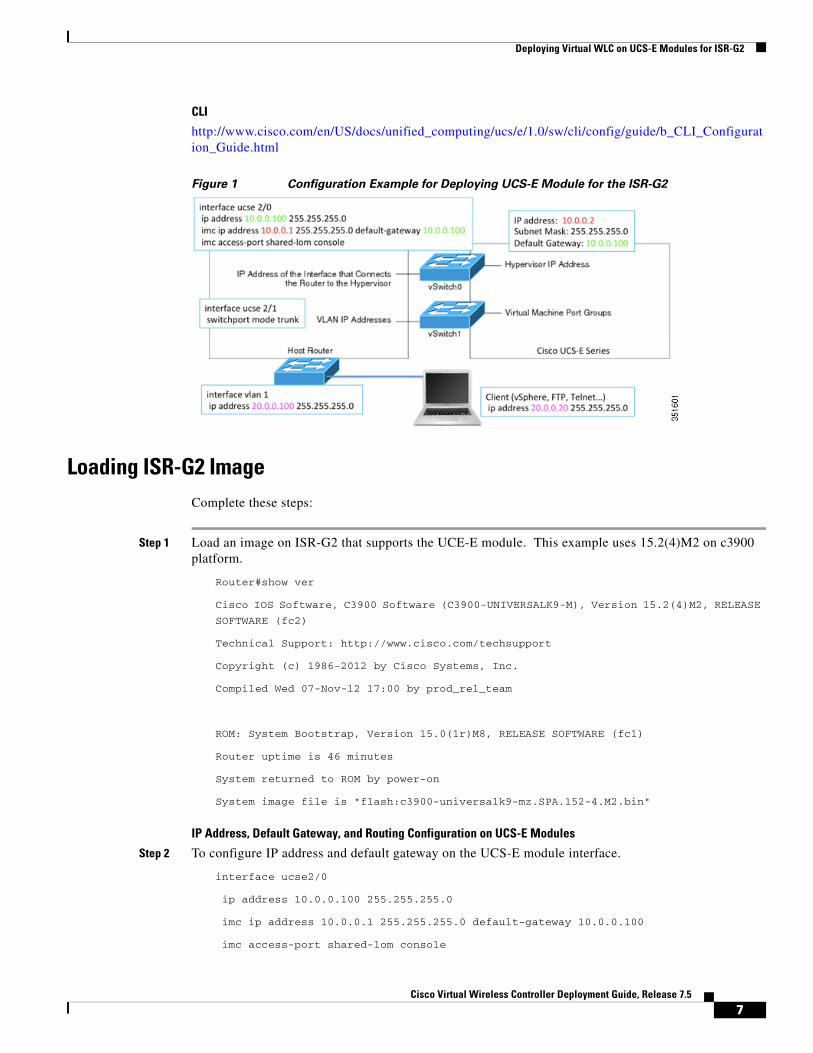
Figure 1 Configuration Example for Deploying UCS-E Module for the ISR-G2
Loading ISR-G2 ImageComplete these steps:
Step 1 Load an image on ISR-G2 that supports the UCE-E module. This example uses 15.2(4)M2 on c3900 platform.
Router#show ver
Cisco IOS Software, C3900 Software (C3900-UNIVERSALK9-M), Version 15.2(4)M2, RELEASE
SOFTWARE (fc2)
Technical Support: http://www.cisco.com/techsupport
Copyright (c) 1986-2012 by Cisco Systems, Inc.
Compiled Wed 07-Nov-12 17:00 by prod_rel_team
ROM: System Bootstrap, Version 15.0(1r)M8, RELEASE SOFTWARE (fc1)
Router uptime is 46 minutes
System returned to ROM by power-on
System image file is "flash:c3900-universalk9-mz.SPA.152-4.M2.bin"
IP Address, Default Gateway, and Routing Configuration on UCS-E Modules
Step 2 To configure IP address and default gateway on the UCS-E module interface.
interface ucse2/0
ip address 10.0.0.100 255.255.255.0
imc ip address 10.0.0.1 255.255.255.0 default-gateway 10.0.0.100
imc access-port shared-lom console
7Cisco Virtual Wireless Controller Deployment Guide, Release 7.5
Deploying Virtual WLC on UCS-E Modules for ISR-G2
!
!
interface ucse2/1
description Internal switch interface connected to Service Module
switchport mode trunk
no ip address
!
Step 3 To add UCS-E module’s IP address routing to the ISR-G2 router.
ip route 10.0.0.2 255.255.255.255 ucse2/0
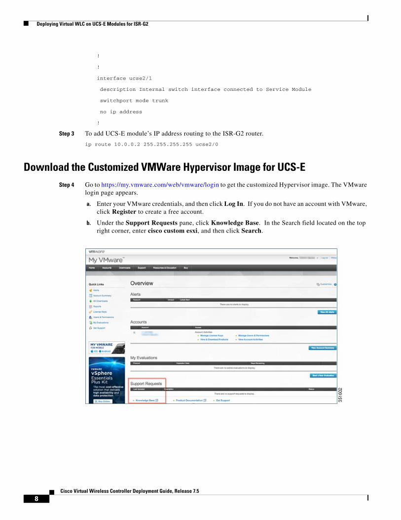
Download the Customized VMWare Hypervisor Image for UCS-EStep 4 Go to https://my.vmware.com/web/vmware/login to get the customized Hypervisor image. The VMware
login page appears.
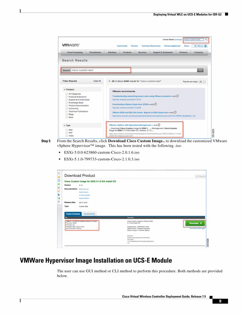
a. Enter your VMware credentials, and then click Log In. If you do not have an account with VMware, click Register to create a free account.
b. Under the Support Requests pane, click Knowledge Base. In the Search field located on the top right corner, enter cisco custom esxi, and then click Search.
8Cisco Virtual Wireless Controller Deployment Guide, Release 7.5
Deploying Virtual WLC on UCS-E Modules for ISR-G2
Step 5 From the Search Results, click Download Cisco Custom Image.. to download the customized VMware vSphere Hypervisor™ image. This has been tested with the following .iso:
• ESXi-5.0.0-623860-custom-Cisco-2.0.1.6.iso
• ESXi-5.1.0-799733-custom-Cisco-2.1.0.3.iso
VMWare Hypervisor Image Installation on UCS-E ModuleThe user can use GUI method or CLI method to perform this procedure. Both methods are provided below.
9Cisco Virtual Wireless Controller Deployment Guide, Release 7.5

Deploying Virtual WLC on UCS-E Modules for ISR-G2
GUI Method using Cisco Integrated Management Controller (CIMC) Interface
Step 6 Open a browser and enter http://<CIMC _ip address> (e.g.10.0.0.1 as configured above).
a. For a new unit, enter admin as username and password as password.
Step 7 CIMC will prompt for a new password – enter new password, then save changes.
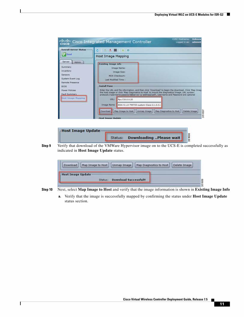
Step 8 Once successfully logged into the CIMC, navigate to Host Image Mapping option in the Server tab.
a. Enter the URL and path to download the Hypervisor image for UCS-E in the Install pane – in this example we are using an FTP server that is also hosting the ISO file.
b. Select download to begin the image download. Host Image Update status should indicate Downloading
10Cisco Virtual Wireless Controller Deployment Guide, Release 7.5
Deploying Virtual WLC on UCS-E Modules for ISR-G2
Step 9 Verify that download of the VMWare Hypervisor image on to the UCS-E is completed successfully as indicated in Host Image Update status.
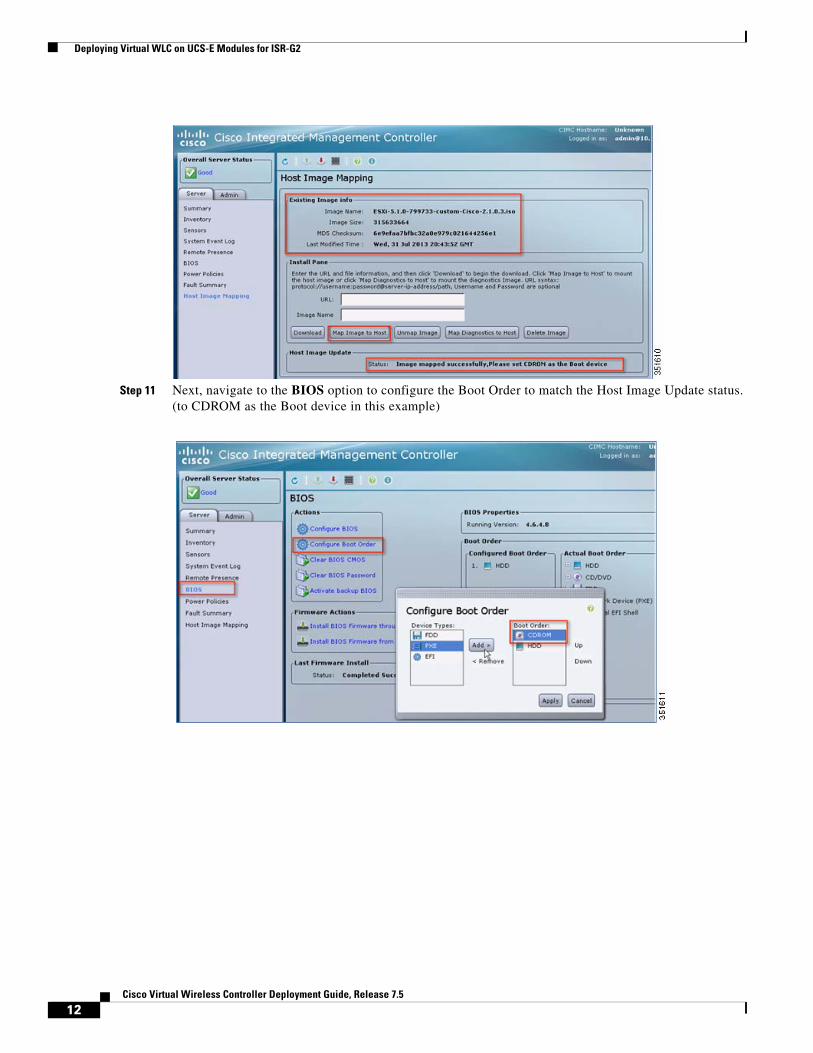
Step 10 Next, select Map Image to Host and verify that the image information is shown in Existing Image Info
a. Verify that the image is successfully mapped by confirming the status under Host Image Update status section.
11Cisco Virtual Wireless Controller Deployment Guide, Release 7.5
Deploying Virtual WLC on UCS-E Modules for ISR-G2
Step 11 Next, navigate to the BIOS option to configure the Boot Order to match the Host Image Update status. (to CDROM as the Boot device in this example)
12Cisco Virtual Wireless Controller Deployment Guide, Release 7.5
Deploying Virtual WLC on UCS-E Modules for ISR-G2
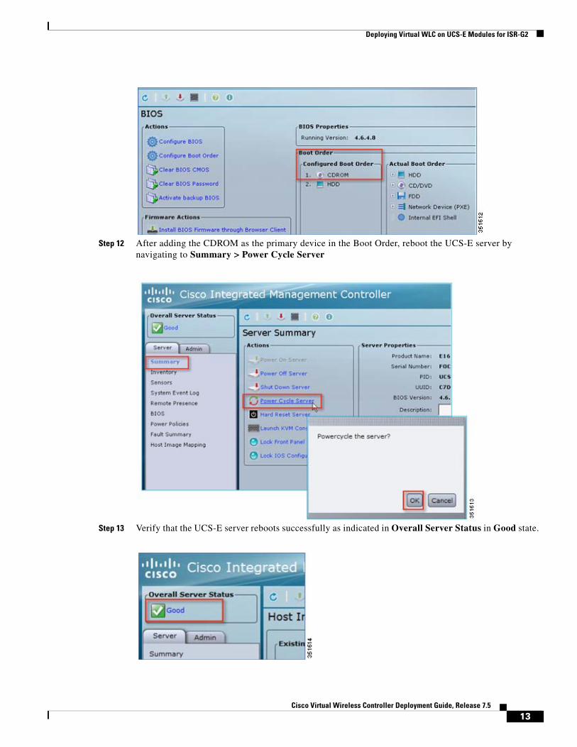
Step 12 After adding the CDROM as the primary device in the Boot Order, reboot the UCS-E server by navigating to Summary > Power Cycle Server
Step 13 Verify that the UCS-E server reboots successfully as indicated in Overall Server Status in Good state.
13Cisco Virtual Wireless Controller Deployment Guide, Release 7.5
Deploying Virtual WLC on UCS-E Modules for ISR-G2
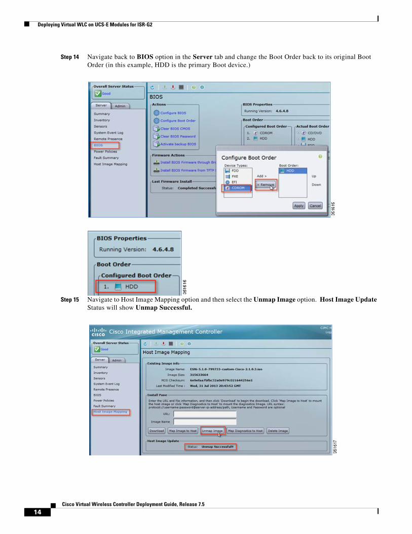
Step 14 Navigate back to BIOS option in the Server tab and change the Boot Order back to its original Boot Order (in this example, HDD is the primary Boot device.)
Step 15 Navigate to Host Image Mapping option and then select the Unmap Image option. Host Image Update Status will show Unmap Successful.
14Cisco Virtual Wireless Controller Deployment Guide, Release 7.5
Deploying Virtual WLC on UCS-E Modules for ISR-G2
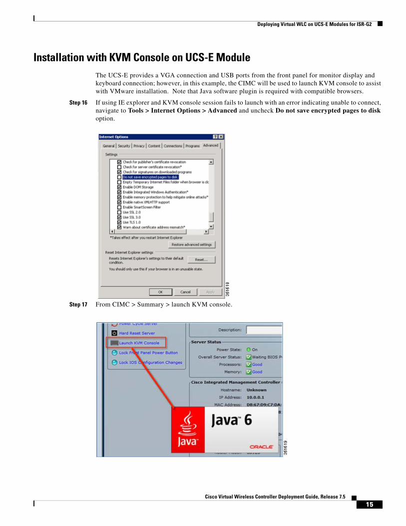
Installation with KVM Console on UCS-E ModuleThe UCS-E provides a VGA connection and USB ports from the front panel for monitor display and keyboard connection; however, in this example, the CIMC will be used to launch KVM console to assist with VMware installation. Note that Java software plugin is required with compatible browsers.
Step 16 If using IE explorer and KVM console session fails to launch with an error indicating unable to connect, navigate to Tools > Internet Options > Advanced and uncheck Do not save encrypted pages to disk option.
Step 17 From CIMC > Summary > launch KVM console.
15Cisco Virtual Wireless Controller Deployment Guide, Release 7.5
Deploying Virtual WLC on UCS-E Modules for ISR-G2
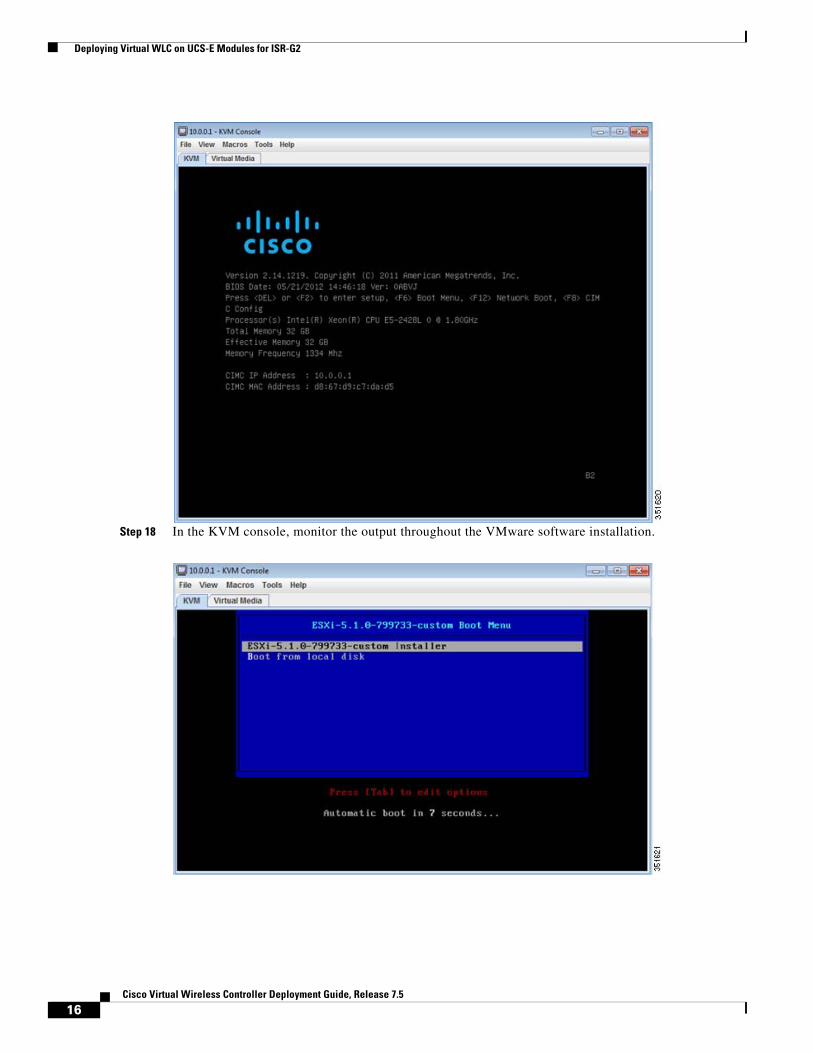
Step 18 In the KVM console, monitor the output throughout the VMware software installation.
16Cisco Virtual Wireless Controller Deployment Guide, Release 7.5
Deploying Virtual WLC on UCS-E Modules for ISR-G2
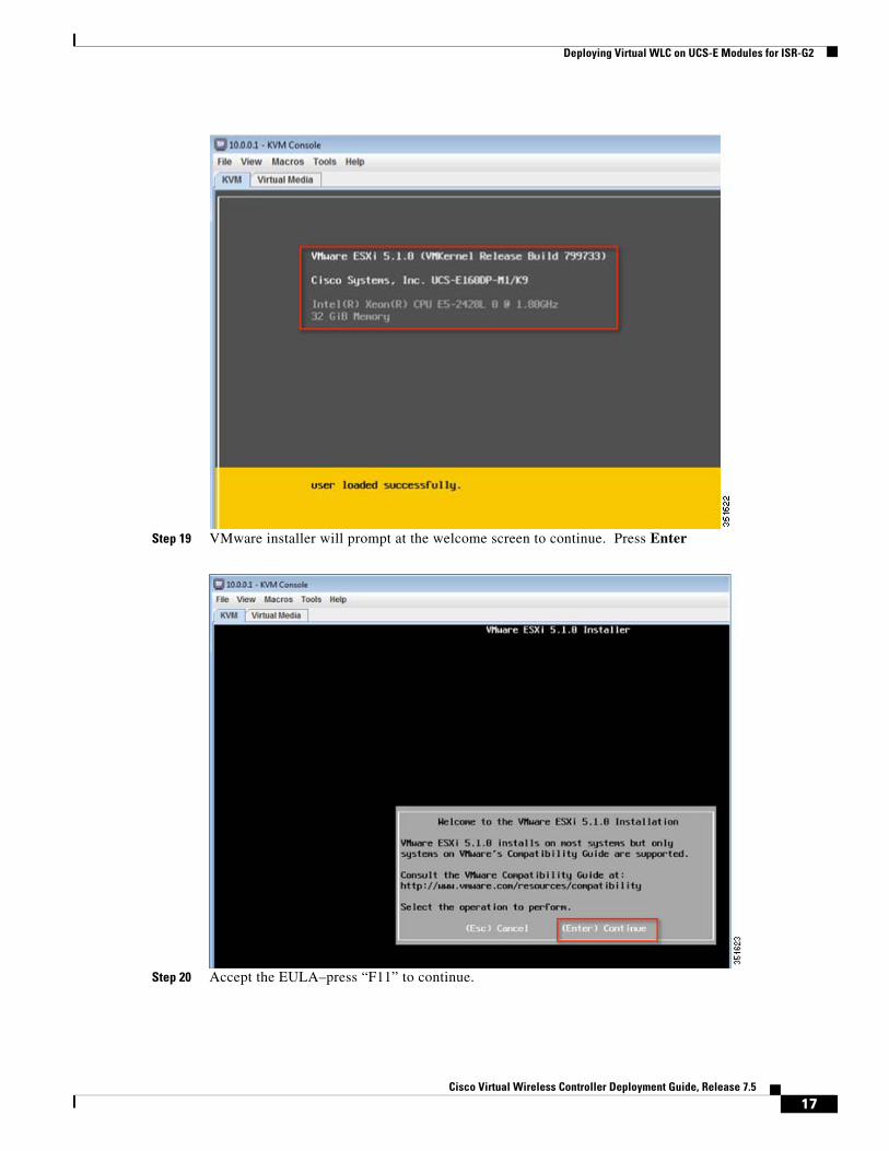
Step 19 VMware installer will prompt at the welcome screen to continue. Press Enter
Step 20 Accept the EULA–press “F11” to continue.
17Cisco Virtual Wireless Controller Deployment Guide, Release 7.5

Deploying Virtual WLC on UCS-E Modules for ISR-G2
Step 21 Make a Disk (or accept default) selection to install, press Enter to continue.
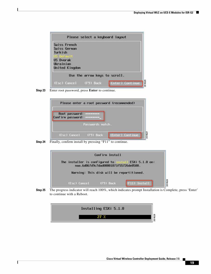
Step 22 Select keyboard layout, press Enter to continue.
18Cisco Virtual Wireless Controller Deployment Guide, Release 7.5
Deploying Virtual WLC on UCS-E Modules for ISR-G2
Step 23 Enter root password, press Enter to continue.
Step 24 Finally, confirm install by pressing “F11” to continue.
Step 25 The progress indicator will reach 100%, which indicates prompt Installation is Complete, press ‘Enter’ to continue with a Reboot.
19Cisco Virtual Wireless Controller Deployment Guide, Release 7.5

Deploying Virtual WLC on UCS-E Modules for ISR-G2
Assign Network and Static IP Address to the VMWare vSphere HypervisorStep 26 Launch KVM console from the CIMC’s Action area of the Server tab
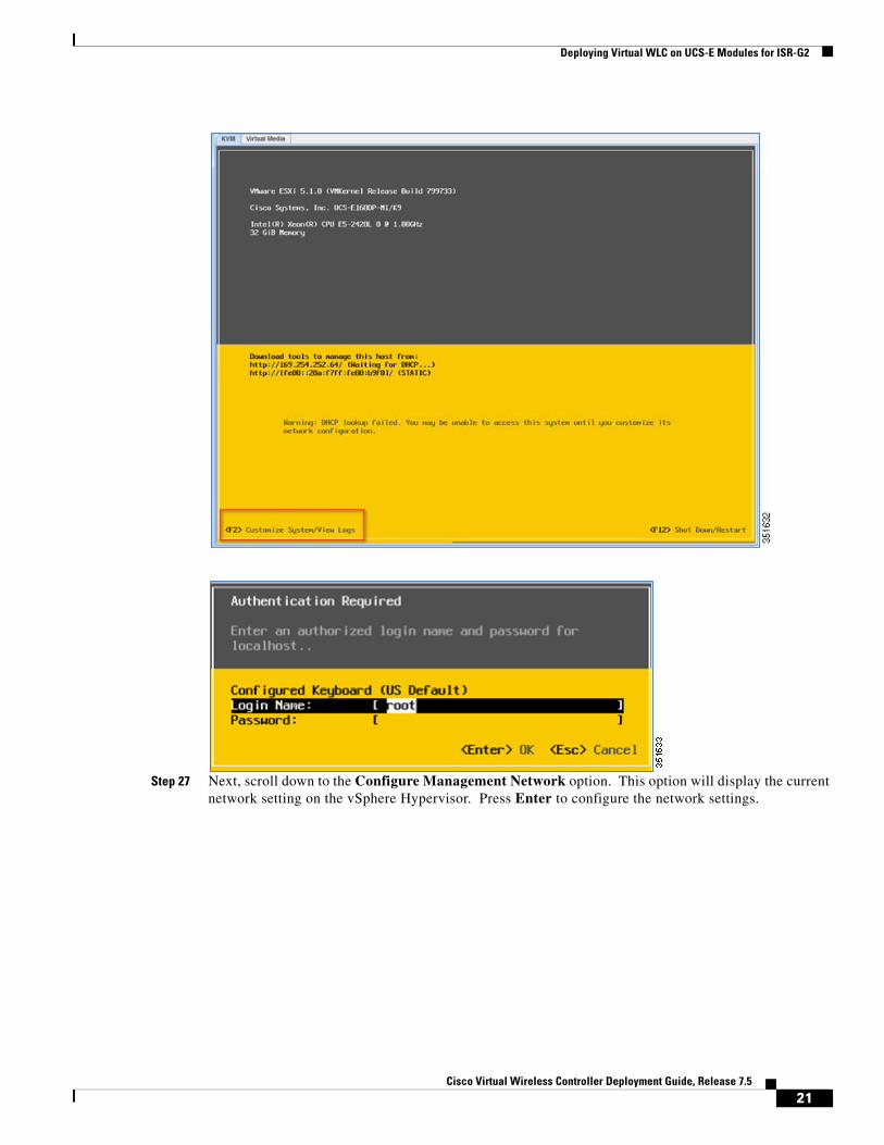
a. Once the KVM console is successfully launched, enter “F2” to enter the Customize System option. Select username and password for vSphere Hypervisor (previously configured).
20Cisco Virtual Wireless Controller Deployment Guide, Release 7.5
Deploying Virtual WLC on UCS-E Modules for ISR-G2
Step 27 Next, scroll down to the Configure Management Network option. This option will display the current network setting on the vSphere Hypervisor. Press Enter to configure the network settings.
21Cisco Virtual Wireless Controller Deployment Guide, Release 7.5
Deploying Virtual WLC on UCS-E Modules for ISR-G2
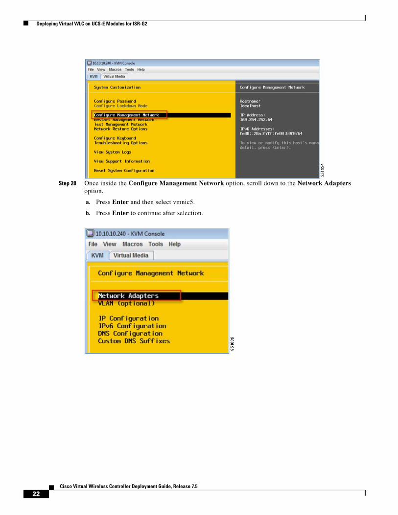
Step 28 Once inside the Configure Management Network option, scroll down to the Network Adapters option.
a. Press Enter and then select vmnic5.
b. Press Enter to continue after selection.
22Cisco Virtual Wireless Controller Deployment Guide, Release 7.5
Deploying Virtual WLC on UCS-E Modules for ISR-G2
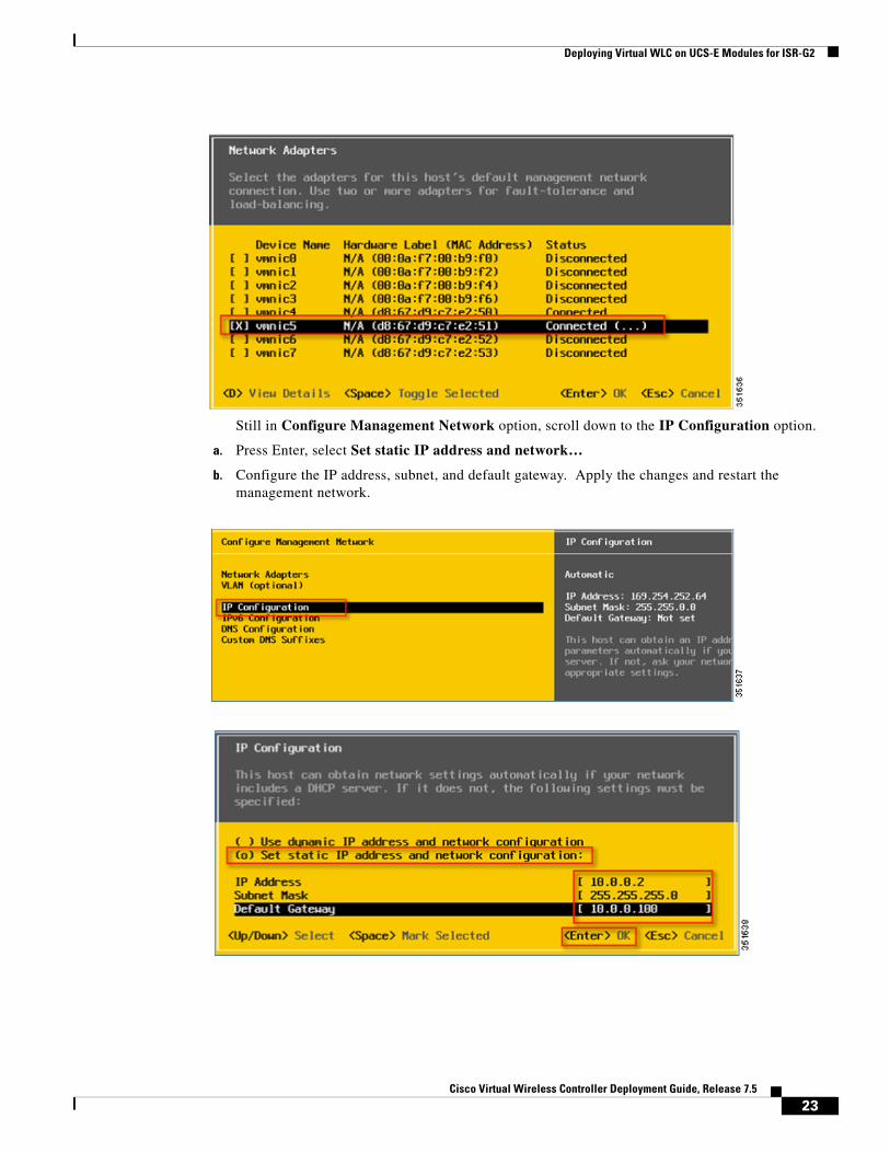
Still in Configure Management Network option, scroll down to the IP Configuration option.
a. Press Enter, select Set static IP address and network…
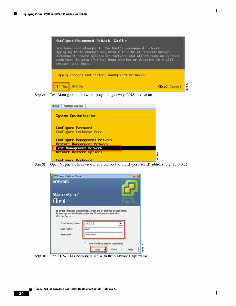
b. Configure the IP address, subnet, and default gateway. Apply the changes and restart the management network.
23Cisco Virtual Wireless Controller Deployment Guide, Release 7.5
Deploying Virtual WLC on UCS-E Modules for ISR-G2
Step 29 Test Management Network–pings the gateway, DNS, and so on.
Step 30 Open VSphere client viewer and connect to the Hypervisor IP address (e.g. 10.0.0.2).
Step 31 The UCS-E has been installed with the VMware Hypervisor.
24Cisco Virtual Wireless Controller Deployment Guide, Release 7.5
Deploying Virtual WLC on SRE Service Modules 710/910 for ISR-G2
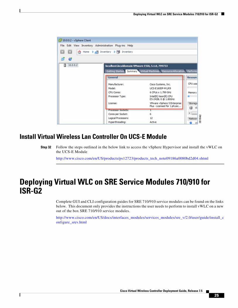
Install Virtual Wireless Lan Controller On UCS-E ModuleStep 32 Follow the steps outlined in the below link to access the vSphere Hypervisor and install the vWLC on
the UCS-E Module
http://www.cisco.com/en/US/products/ps12723/products_tech_note09186a0080bd2d04.shtml
Deploying Virtual WLC on SRE Service Modules 710/910 for ISR-G2
Complete GUI and CLI configuration guides for SRE 710/910 service modules can be found on the links below. This document only provides the instructions the user needs to perform to install vWLC on a new out of the box SRE 710/910 service modules.
http://www.cisco.com/en/US/docs/interfaces_modules/services_modules/sre_v/2.0/user/guide/install_configure_srev.html
25Cisco Virtual Wireless Controller Deployment Guide, Release 7.5
Deploying Virtual WLC on SRE Service Modules 710/910 for ISR-G2
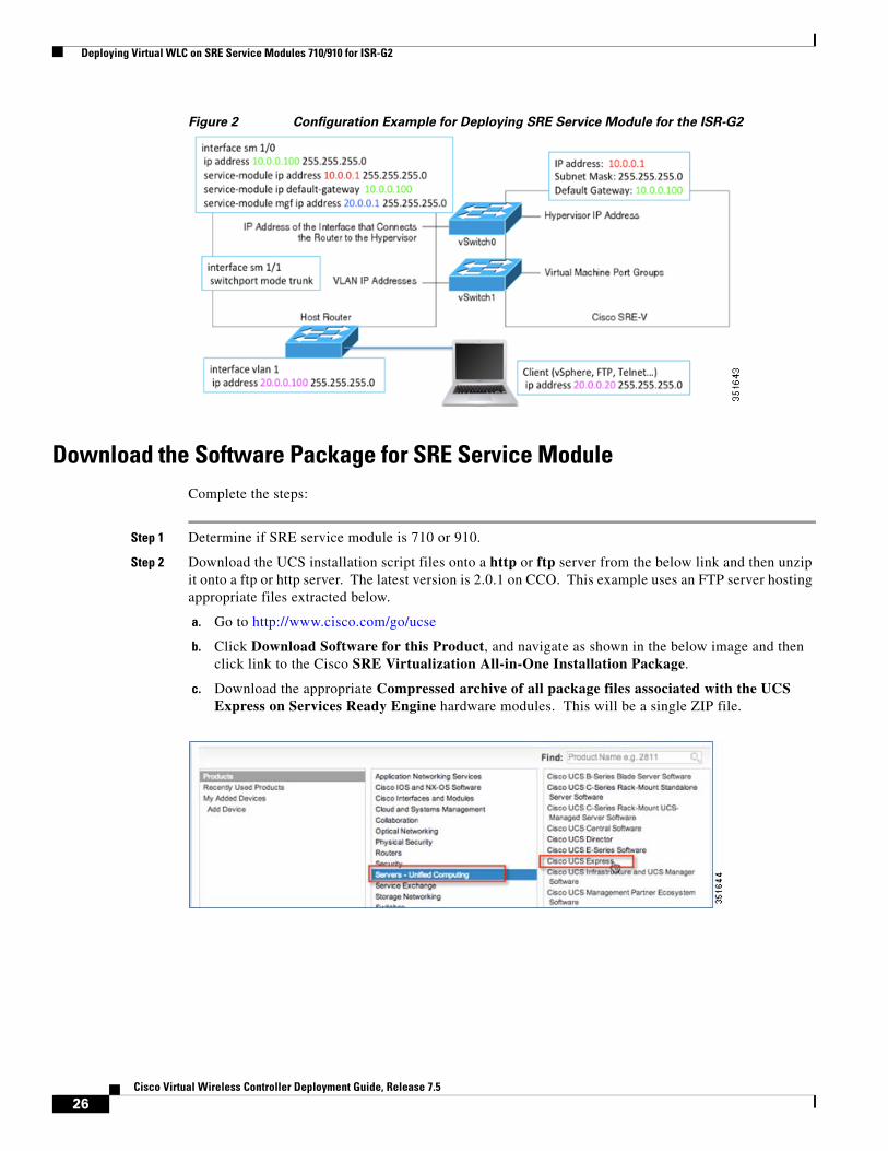
Figure 2 Configuration Example for Deploying SRE Service Module for the ISR-G2
Download the Software Package for SRE Service ModuleComplete the steps:
Step 1 Determine if SRE service module is 710 or 910.
Step 2 Download the UCS installation script files onto a http or ftp server from the below link and then unzip it onto a ftp or http server. The latest version is 2.0.1 on CCO. This example uses an FTP server hosting appropriate files extracted below.
a. Go to http://www.cisco.com/go/ucse
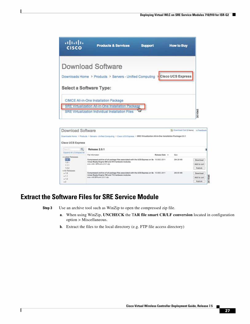
b. Click Download Software for this Product, and navigate as shown in the below image and then click link to the Cisco SRE Virtualization All-in-One Installation Package.
c. Download the appropriate Compressed archive of all package files associated with the UCS Express on Services Ready Engine hardware modules. This will be a single ZIP file.
26Cisco Virtual Wireless Controller Deployment Guide, Release 7.5
Deploying Virtual WLC on SRE Service Modules 710/910 for ISR-G2
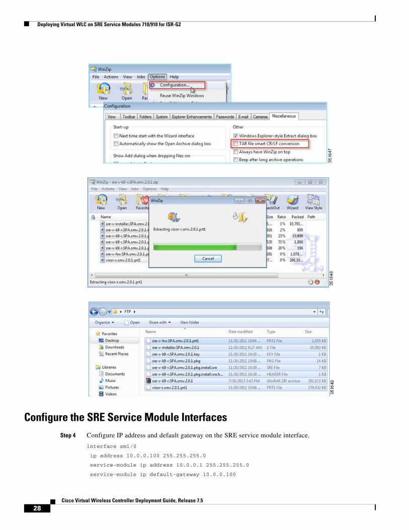
Extract the Software Files for SRE Service ModuleStep 3 Use an archive tool such as WinZip to open the compressed zip file.
a. When using WinZip, UNCHECK the TAR file smart CR/LF conversion located in configuration option > Miscellaneous.
b. Extract the files to the local directory (e.g. FTP file access directory)
27Cisco Virtual Wireless Controller Deployment Guide, Release 7.5
Deploying Virtual WLC on SRE Service Modules 710/910 for ISR-G2
Configure the SRE Service Module InterfacesStep 4 Configure IP address and default gateway on the SRE service module interface.
interface sm1/0
ip address 10.0.0.100 255.255.255.0
service-module ip address 10.0.0.1 255.255.255.0
service-module ip default-gateway 10.0.0.100
28Cisco Virtual Wireless Controller Deployment Guide, Release 7.5
Deploying Virtual WLC on SRE Service Modules 710/910 for ISR-G2
service-module mgf ip address 20.0.0.1 255.255.255.0
no shutdown
!
interface sm1/1
description Internal switch interface connected to Service Module
switchport mode trunk
!
Step 5 Add UCS-E module’s IP address routing to the ISR-G2 router
ip route 10.0.0.2 255.255.255.255 sm1/0
Start the Hypervisor Install Script for SRE Service ModuleStep 6 From the ISR router, use the service-module install command to load the UCS script files onto the
SRE module. Please note that this step takes approximately 10 minutes to complete.
a. Example command from router console:
service-module <sm number> install url <ftp/http:[ip_addr/path/file>
b. Press Enter at two prompts (Proceed and Disk selection) to accept defaults to continue.
Actual Example OutputRouter#service-module sm 1/0 install url ftp://20.0.0.20/sre-v-k9-r.SPA.smv.2.0.1.pkg
Proceed with installation? [no]: yes <<Press Enter>>
Loading sre-v-k9-r.SPA.smv.2.0.1.pkg.install.sre !
[OK - 6520/4096 bytes]
Service module installation
ios_version 15.2(4)M2,
ios_image c3900-universalk9-mz
pkg_name sre-v-k9-r.SPA.smv.2.0.1.pkg
key_file sre-v-k9-r.SPA.smv.2.0.1.key
helper_file sre-v-installer.SPA.smv.2.0.1
pid SM-SRE-910-K9
Check target platform capabilities
cpu 1864
Please select disk configuration (-1 = nonraid, 0 = raid0, 1 = raid1 ) [-1]: <<Press Enter>>
Resource check completed successfully. Proceeding to Install ...
Router#
*Aug 1 17:50:45.203: %SM_INSTALL-6-INST_RESET: SM1/0 is reset for software installation.
*Aug 1 17:52:14.323: %SM_INSTALL-6-INST_RBIP: SM1/0 received msg: RBIP Registration Request
*Aug 1 17:52:14.327: %SM_INSTALL-6-INST_RBIP: SM1/0 received msg: RBIP File Request
*Aug 1 17:52:17.715: %SM_INSTALL-6-INST_RBIP: SM1/0 received msg: RBIP File Request
*Aug 1 17:52:23.543: %SM_INSTALL-6-INST_RBIP: SM1/0 received msg: RBIP File Request
*Aug 1 17:52:23.575: %SM_INSTALL-6-INST_RBIP: SM1/0 received msg: RBIP File Request
29Cisco Virtual Wireless Controller Deployment Guide, Release 7.5

Deploying Virtual WLC on SRE Service Modules 710/910 for ISR-G2
*Aug 1 17:52:51.811: %SRE_SM-6-STATE_CHANGE: SM1/0 changing state from SERVICE_MODULE_STATE_ERRQ to SERVICE_MODULE_STATE_STDY
*Aug 1 17:53:02.799: %SM_INSTALL-6-INST_PROG: SM1/0 PROGRESSING: Validating package signature ....
*Aug 1 17:53:02.915: %SM_INSTALL-6-INST_PROG: SM1/0 PROGRESSING: Parsing package manifest files ....
*Aug 1 17:53:19.811: %SM_INSTALL-6-INST_PROG: SM1/0 PROGRESSING: Starting payload download.
*Aug 1 17:53:21.067: %SM_INSTALL-6-INST_PROG: SM1/0 PROGRESSING: Starting payload download.
*Aug 1 17:53:51.143: %SM_INSTALL-6-INST_PROG: SM1/0 PROGRESSING: Performing Hot install ....
*Aug 1 17:54:53.483: %SM_INSTALL-6-INST_PROG: SM1/0 PROGRESSING: Updating BIOS sata mode to ahci .
Install successful on SM1/0. Please wait for module to reset before next operation.
<<SUCCESS>>
*Aug 1 17:55:01.395: %SM_INSTALL-6-INST_SUCC_RESET: SM1/0 SUCCESS: install-completed. Please wait for module to reset before next operation
*Aug 1 17:55:15.247: %DTP-5-NONTRUNKPORTON: Port SM1/1 has become non-trunk
*Aug 1 17:55:16.247: %DTP-5-TRUNKPORTON: Port SM1/1 has become dot1q trunk
*Aug 1 17:56:30.803: %SM_INSTALL-6-INST_RBIP: SM1/0 received msg: RBIP Status Req
*Aug 1 17:56:30.803: %SM_INSTALL-6-RBIP_STATUS: SM1/0 RBIP status is at Secondary Bootloader Verified Copying to Primary.
*Aug 1 17:57:02.439: %SM_INSTALL-6-INST_RBIP: SM1/0 received msg: RBIP Registration Request
*Aug 1 17:57:02.439: %SM_INSTALL-6-INST_RESET_COMP: SM1/0: Module reset complete.
Step 7 To show the status of the service module.
a. Type in the command service-module sm 1/0 status
Router#service-module sm 1/0 status
Service Module is Cisco SM1/0
Service Module supports session via TTY line 67
Service Module is in Steady state
Service Module heartbeat-reset is enabled
Getting status from the Service Module, please wait..
Cisco SRE-V Software 2.0.1.0
VMware ESXi 5.0.0 build-474610 running on SRE <<This shows VMware Hypervisor has been installed>>
No install/uninstall in progress
Connecting to Hypervisor on the SRE 710/910 Service Module on ISR G2Step 8 Console access to hypervisor from the router with the command service-module <sm number> session
a. Note that VMware Hypervisor has been installed, showing on a CISCO SRE.
b. The IP address has been defined by the command in the interface configuration steps service-module ip address
Router#service-module sm 1/0 session
30Cisco Virtual Wireless Controller Deployment Guide, Release 7.5

Deploying Virtual WLC on SRE Service Modules 710/910 for ISR-G2
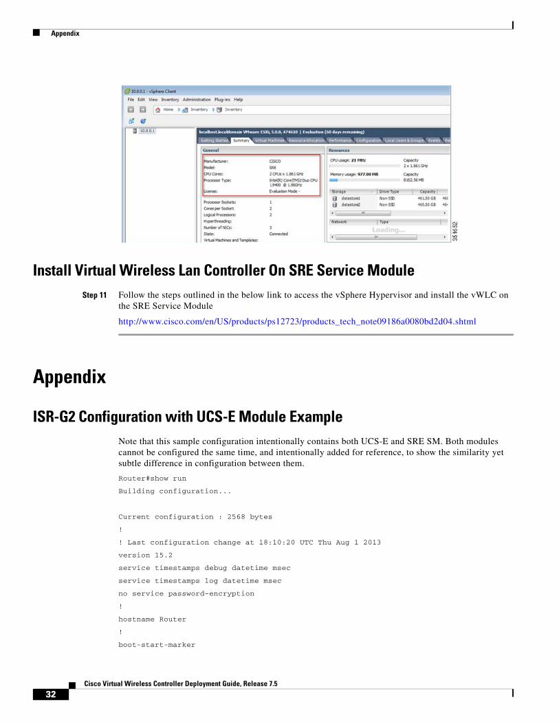
Step 9 Use vSphere Client viewer to connect to the Hypervisor.
a. Log in with default username root, there is no default password initially.
Step 10 The Hypervisor is successfully installed and configured on the SRE service module.
31Cisco Virtual Wireless Controller Deployment Guide, Release 7.5
Appendix
Install Virtual Wireless Lan Controller On SRE Service ModuleStep 11 Follow the steps outlined in the below link to access the vSphere Hypervisor and install the vWLC on
the SRE Service Module
http://www.cisco.com/en/US/products/ps12723/products_tech_note09186a0080bd2d04.shtml
Appendix
ISR-G2 Configuration with UCS-E Module ExampleNote that this sample configuration intentionally contains both UCS-E and SRE SM. Both modules cannot be configured the same time, and intentionally added for reference, to show the similarity yet subtle difference in configuration between them.
Router#show run
Building configuration...
Current configuration : 2568 bytes
!
! Last configuration change at 18:10:20 UTC Thu Aug 1 2013
version 15.2
service timestamps debug datetime msec
service timestamps log datetime msec
no service password-encryption
!
hostname Router
!
boot-start-marker
32Cisco Virtual Wireless Controller Deployment Guide, Release 7.5

Appendix
boot system flash:c3900-universalk9-mz.SPA.152-4.M2.bin
boot-end-marker
!
no aaa new-model
!
ip cef
!
!
no ip domain lookup
no ipv6 cef
multilink bundle-name authenticated
!
!
license udi pid C3900-SPE100/K9 sn FOC14415CF8
hw-module sm 1
!
hw-module sm 2
!
!
csdb tcp synwait-time 30
csdb tcp idle-time 3600
csdb tcp finwait-time 5
csdb tcp reassembly max-memory 1024
csdb tcp reassembly max-queue-length 16
csdb udp idle-time 30
csdb icmp idle-time 10
csdb session max-session 65535
!
!
interface Embedded-Service-Engine0/0
no ip address
shutdown
!
interface GigabitEthernet0/0
ip address 10.10.10.44 255.255.255.0
duplex auto
speed auto
!
interface GigabitEthernet0/1
no ip address
shutdown
duplex auto
speed auto
!
interface GigabitEthernet0/2
no ip address
33Cisco Virtual Wireless Controller Deployment Guide, Release 7.5
Appendix
shutdown
duplex auto
speed auto
!
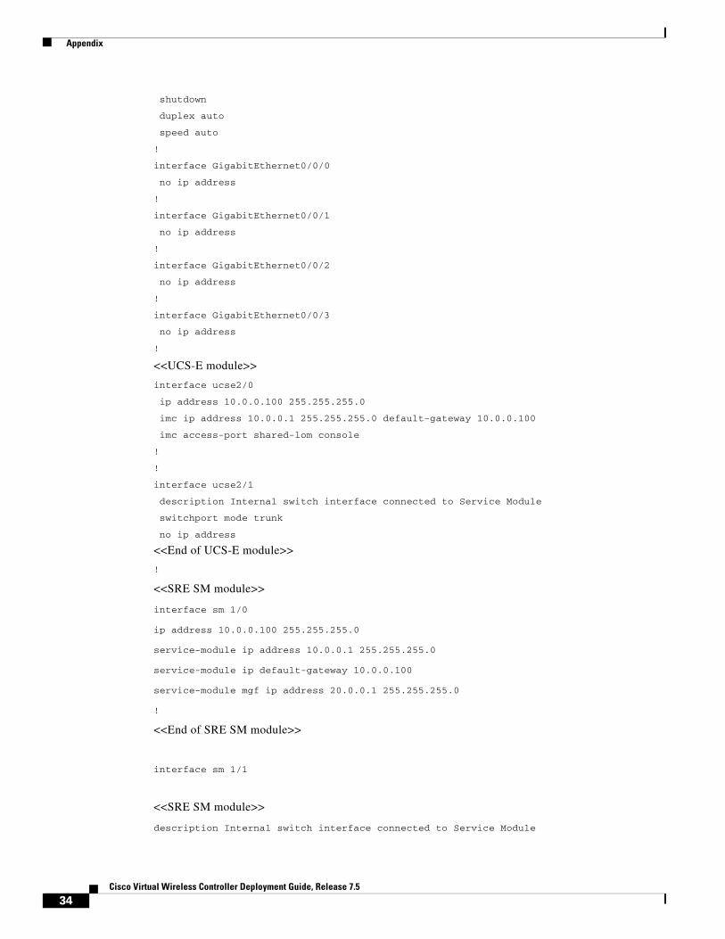
interface GigabitEthernet0/0/0
no ip address
!
interface GigabitEthernet0/0/1
no ip address
!
interface GigabitEthernet0/0/2
no ip address
!
interface GigabitEthernet0/0/3
no ip address
!
<<UCS-E module>>
interface ucse2/0
ip address 10.0.0.100 255.255.255.0
imc ip address 10.0.0.1 255.255.255.0 default-gateway 10.0.0.100
imc access-port shared-lom console
!
!
interface ucse2/1
description Internal switch interface connected to Service Module
switchport mode trunk
no ip address
<<End of UCS-E module>>
!
<<SRE SM module>>
interface sm 1/0
ip address 10.0.0.100 255.255.255.0
service-module ip address 10.0.0.1 255.255.255.0
service-module ip default-gateway 10.0.0.100
service-module mgf ip address 20.0.0.1 255.255.255.0
!
<<End of SRE SM module>>
interface sm 1/1
<<SRE SM module>>
description Internal switch interface connected to Service Module
34Cisco Virtual Wireless Controller Deployment Guide, Release 7.5

Appendix
switchport mode trunk
no ip address
<<End of SRE SM module>>
!
interface Vlan1
ip address 20.0.0.100 255.255.255.0
!
ip forward-protocol nd
!
no ip http server
no ip http secure-server
!
ip route 10.0.0.2 255.255.255.255 ucse2/0 –//UCS-E module
ip route 10.0.0.2 255.255.255.255 sm 1/0 –// SRE SM module
!
control-plane
!
!
!
line con 0
line aux 0
line 2
no activation-character
no exec
transport preferred none
transport input all
transport output pad telnet rlogin lapb-ta mop udptn v120 ssh
stopbits 1
line 67
no activation-character
no exec
transport preferred none
transport input all
transport output pad telnet rlogin lapb-ta mop udptn v120 ssh
stopbits 1
line 131
no activation-character
no exec
transport preferred none
transport input all
transport output pad telnet rlogin lapb-ta mop udptn v120 ssh
stopbits 1
speed 9600
flowcontrol software
35Cisco Virtual Wireless Controller Deployment Guide, Release 7.5
Appendix
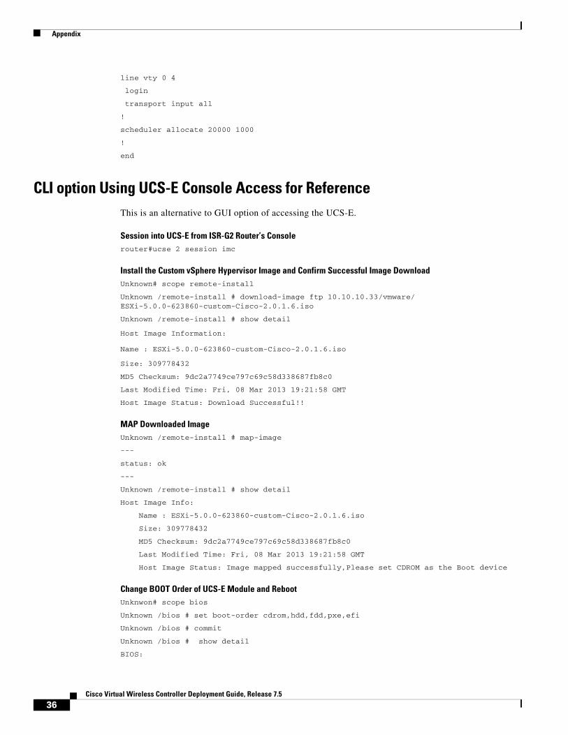
line vty 0 4
login
transport input all
!
scheduler allocate 20000 1000
!
end
CLI option Using UCS-E Console Access for ReferenceThis is an alternative to GUI option of accessing the UCS-E.
Session into UCS-E from ISR-G2 Router’s Consolerouter#ucse 2 session imc
Install the Custom vSphere Hypervisor Image and Confirm Successful Image DownloadUnknown# scope remote-install
Unknown /remote-install # download-image ftp 10.10.10.33/vmware/ ESXi-5.0.0-623860-custom-Cisco-2.0.1.6.iso
Unknown /remote-install # show detail
Host Image Information:
Name : ESXi-5.0.0-623860-custom-Cisco-2.0.1.6.iso
Size: 309778432
MD5 Checksum: 9dc2a7749ce797c69c58d338687fb8c0
Last Modified Time: Fri, 08 Mar 2013 19:21:58 GMT
Host Image Status: Download Successful!!
MAP Downloaded Image Unknown /remote-install # map-image
---
status: ok
---
Unknown /remote-install # show detail
Host Image Info:
Name : ESXi-5.0.0-623860-custom-Cisco-2.0.1.6.iso
Size: 309778432
MD5 Checksum: 9dc2a7749ce797c69c58d338687fb8c0
Last Modified Time: Fri, 08 Mar 2013 19:21:58 GMT
Host Image Status: Image mapped successfully,Please set CDROM as the Boot device
Change BOOT Order of UCS-E Module and Reboot Unknwon# scope bios
Unknown /bios # set boot-order cdrom,hdd,fdd,pxe,efi
Unknown /bios # commit
Unknown /bios # show detail
BIOS:
36Cisco Virtual Wireless Controller Deployment Guide, Release 7.5
Appendix
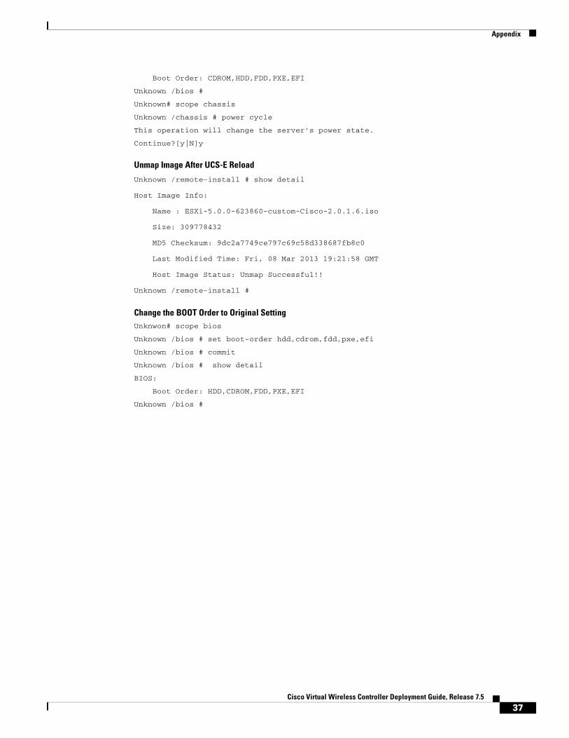
Boot Order: CDROM,HDD,FDD,PXE,EFI
Unknown /bios #
Unknown# scope chassis
Unknown /chassis # power cycle
This operation will change the server's power state.
Continue?[y|N]y
Unmap Image After UCS-E Reload
Unknown /remote-install # show detail
Host Image Info:
Name : ESXi-5.0.0-623860-custom-Cisco-2.0.1.6.iso
Size: 309778432
MD5 Checksum: 9dc2a7749ce797c69c58d338687fb8c0
Last Modified Time: Fri, 08 Mar 2013 19:21:58 GMT
Host Image Status: Unmap Successful!!
Unknown /remote-install #
Change the BOOT Order to Original SettingUnknwon# scope bios
Unknown /bios # set boot-order hdd,cdrom,fdd,pxe,efi
Unknown /bios # commit
Unknown /bios # show detail
BIOS:
Boot Order: HDD,CDROM,FDD,PXE,EFI
Unknown /bios #
37Cisco Virtual Wireless Controller Deployment Guide, Release 7.5

Appendix
38Cisco Virtual Wireless Controller Deployment Guide, Release 7.5