Embed Size (px)
Citation preview

Cisco Unified Serviceability Administration Guide, Release 10.0(1)First Published: December 03, 2013
Americas HeadquartersCisco Systems, Inc.170 West Tasman DriveSan Jose, CA 95134-1706USAhttp://www.cisco.comTel: 408 526-4000 800 553-NETS (6387)Fax: 408 527-0883
Text Part Number: OL-29842-01

THE SPECIFICATIONS AND INFORMATION REGARDING THE PRODUCTS IN THIS MANUAL ARE SUBJECT TO CHANGE WITHOUT NOTICE. ALL STATEMENTS,INFORMATION, AND RECOMMENDATIONS IN THIS MANUAL ARE BELIEVED TO BE ACCURATE BUT ARE PRESENTED WITHOUT WARRANTY OF ANY KIND,EXPRESS OR IMPLIED. USERS MUST TAKE FULL RESPONSIBILITY FOR THEIR APPLICATION OF ANY PRODUCTS.
THE SOFTWARE LICENSE AND LIMITEDWARRANTY FOR THE ACCOMPANYING PRODUCT ARE SET FORTH IN THE INFORMATION PACKET THAT SHIPPED WITHTHE PRODUCT AND ARE INCORPORATED HEREIN BY THIS REFERENCE. IF YOU ARE UNABLE TO LOCATE THE SOFTWARE LICENSE OR LIMITED WARRANTY,CONTACT YOUR CISCO REPRESENTATIVE FOR A COPY.
The Cisco implementation of TCP header compression is an adaptation of a program developed by the University of California, Berkeley (UCB) as part of UCB's public domain versionof the UNIX operating system. All rights reserved. Copyright © 1981, Regents of the University of California.
NOTWITHSTANDINGANYOTHERWARRANTYHEREIN, ALL DOCUMENT FILES AND SOFTWARE OF THESE SUPPLIERS ARE PROVIDED “AS IS"WITH ALL FAULTS.CISCO AND THE ABOVE-NAMED SUPPLIERS DISCLAIM ALL WARRANTIES, EXPRESSED OR IMPLIED, INCLUDING, WITHOUT LIMITATION, THOSE OFMERCHANTABILITY, FITNESS FORA PARTICULAR PURPOSEANDNONINFRINGEMENTORARISING FROMACOURSEOFDEALING, USAGE, OR TRADE PRACTICE.
IN NO EVENT SHALL CISCO OR ITS SUPPLIERS BE LIABLE FOR ANY INDIRECT, SPECIAL, CONSEQUENTIAL, OR INCIDENTAL DAMAGES, INCLUDING, WITHOUTLIMITATION, LOST PROFITS OR LOSS OR DAMAGE TO DATA ARISING OUT OF THE USE OR INABILITY TO USE THIS MANUAL, EVEN IF CISCO OR ITS SUPPLIERSHAVE BEEN ADVISED OF THE POSSIBILITY OF SUCH DAMAGES.
Any Internet Protocol (IP) addresses and phone numbers used in this document are not intended to be actual addresses and phone numbers. Any examples, command display output, networktopology diagrams, and other figures included in the document are shown for illustrative purposes only. Any use of actual IP addresses or phone numbers in illustrative content is unintentionaland coincidental.
Cisco and the Cisco logo are trademarks or registered trademarks of Cisco and/or its affiliates in the U.S. and other countries. To view a list of Cisco trademarks, go to this URL: http://www.cisco.com/go/trademarks. Third-party trademarks mentioned are the property of their respective owners. The use of the word partner does not imply a partnershiprelationship between Cisco and any other company. (1110R)
© 2002-2013 Cisco Systems, Inc. All rights reserved.

C O N T E N T S
P r e f a c e Preface xi
Purpose xi
Audience xii
Related documentation xii
Conventions xii
Obtain documentation, support, and security guidelines xiv
Cisco product security overview xiv
Documentation organization xiv
C H A P T E R 1 Seviceability Administrative Overview 1
Overview 1
Reporting tools 2
Remote serviceability tools 3
Customized login message 3
Browser support 3
C H A P T E R 2 Getting Started 5
Access 5
Access Cisco Unified IM and Presence Serviceability 6
Install server certificate 7
HTTPS 7
Install Internet Explorer 7 certificate 8
Serviceability interface 9
C H A P T E R 3 Alarms 13
Overview 13
Alarm configuration 14
Cisco Unified Serviceability Administration Guide, Release 10.0(1) OL-29842-01 iii

Alarm definitions 15
Alarm information 16
Set up alarms 16
Alarm service setup 17
Syslog agent enterprise parameters 17
Set up alarm service 17
Set up alarm service that use Cisco Tomcat 19
Service groups 19
Alarm configuration settings 20
Alarm definitions and user-defined description additions 24
View alarm definitions and add user-defined descriptions 24
System alarm catalog descriptions 25
CallManager alarm catalog descriptions 26
IM and Presence Alarm Catalog descriptions 27
C H A P T E R 4 Trace 29
Trace 29
Trace configuration 30
Trace settings 30
Trace collection 31
Called Party Tracing 31
Set up trace configuration 31
Configure trace 32
Set up trace parameters 32
Service groups in trace configuration 34
Debug trace level settings 40
Trace field descriptions 41
Database layer monitor trace fields 41
Cisco RIS data collector trace fields 42
Cisco CallManager SDI trace fields 43
Cisco CallManager SDL trace fields 44
Cisco CTIManager SDL trace fields 46
Cisco Extended Functions trace fields 47
Cisco Extension Mobility trace fields 48
Cisco IP manager assistant trace fields 49
Cisco Unified Serviceability Administration Guide, Release 10.0(1)iv OL-29842-01
Contents

Cisco IP voice media streaming app trace fields 49
Cisco TFTP trace fields 50
Cisco Web Dialer web service trace fields 50
IM and Presence SIP proxy service trace filter settings 51
IM and Presence trace field descriptions 52
Cisco Access Log trace fields 52
Cisco Authentication trace fields 52
Cisco Calendar trace fields 52
Cisco CTI Gateway trace fields 53
Cisco Database Layer Monitor trace fields 53
Cisco Enum trace fields 53
Cisco Method/Event trace fields 53
Cisco Number Expansion trace fields 54
Cisco Parser trace fields 54
Cisco Privacy trace fields 54
Cisco Proxy trace fields 54
Cisco RIS Data Collector trace fields 55
Cisco Registry trace fields 55
Cisco Routing trace fields 56
Cisco Server trace fields 56
Cisco SIP Message and State Machine trace fields 56
Cisco SIP TCP trace fields 56
Cisco SIP TLS trace fields 57
Cisco Web Service trace fields 57
Trace output settings 57
Trace setting troubleshooting 58
Troubleshoot trace settings window 58
Troubleshoot trace settings 58
C H A P T E R 5 Services 61
Feature services 61
Database and administration services 62
Locations Bandwidth Manager 62
Cisco AXL Web Service 62
Cisco UXL Web Service 62
Cisco Unified Serviceability Administration Guide, Release 10.0(1) OL-29842-01 v
Contents

Cisco Bulk Provisioning Service 63
Platform Administrative Web Service 63
Cisco TAPS Service 63
Platform Administrative Web Service 63
Performance and monitoring services 64
Cisco Serviceability Reporter 64
Cisco CallManager SNMP Service 64
CM services 64
Cisco CallManager 64
Cisco TFTP 65
Cisco Unified Mobile Voice Access Service 65
Cisco IP Voice Media Streaming App 66
Cisco CTIManager 66
Cisco Extension Mobility 66
Cisco Dialed Number Analyzer 66
Cisco Dialed Number Analyzer Server 66
Cisco DHCP Monitor Service 67
Cisco Intercluster Lookup Service 67
Cisco UserSync Service 67
Cisco UserLookup Web Service 67
IM and Presence services 67
Cisco SIP Proxy 67
Cisco Presence Engine 67
Cisco XCP Text Conference Manager 68
Cisco XCP Web Connection Manager 68
Cisco XCP Connection Manager 68
Cisco XCP SIP Federation Connection Manager 68
Cisco XCP XMPP Federation Connection Manager 68
Cisco XCP Message Archiver 68
Cisco XCP Directory Service 68
Cisco XCP Authentication Service 69
CTI services 69
Cisco IP Manager Assistant 69
Cisco WebDialer Web Service 69
Self-Provisioning IVR 69
Cisco Unified Serviceability Administration Guide, Release 10.0(1)vi OL-29842-01
Contents
CDR services 70
CAR Web Service 70
Cisco SOAP - CDRonDemand Service 70
Security services 70
Cisco CTL Provider 70
Cisco Certificate Authority Proxy Function (CAPF) 71
Directory services 71
Cisco DirSync 71
Voice quality reporter services 71
Cisco Extended Functions 72
Network services 72
Performance and monitoring services 72
Backup and restore services 73
System services 73
Platform services 74
Security services 75
Database services 76
SOAP services 76
CM Services 77
IM and Presence Service services 77
CDR services 79
Admin services 80
Services setup 81
Control center 81
Set up services 81
Service activation 82
Cluster service activation recommendations for Cisco Unified Communications Manager 82
Cluster service activation recommendations for IM and Presence Service 86
Activate feature services 89
Start, stop, and restart services in Control Center or CLI 90
Start, stop, and restart services in Control Center 90
Start, stop, and restart services using command line interface 91
C H A P T E R 6 Tools and Reports 93
Serviceability Reports Archive 93
Cisco Unified Serviceability Administration Guide, Release 10.0(1) OL-29842-01 vii
Contents

Serviceability Reporter service parameters 94
Device Statistics Report 94
Server statistics report 97
Service Statistics Report 100
Call activities report 103
Alert summary report 107
Performance Protection Report 109
Set up serviceability reports archive overview 110
Set up Serviceability Reports Archive 111
Access to Serviceability Reports Archive 112
Activate Serviceability Reports Archive 112
Access Serviceability Reports Archive 112
CDR Repository Manager 113
Set up general parameters 114
General parameter settings 115
Set up application billing servers 116
Application billing server parameter settings 117
Delete application billing servers 118
Audit logs 118
Audit logging 119
System audit logs 123
Application audit logs 123
Database audit logs 123
Set up audit log 124
Audit log configuration settings 124
Locations 128
Locations Topology 128
View locations topology 128
View assertion details 129
Locations discrepancy 130
View locations discrepancy 130
Effective path 130
View effective path 131
Disconnected groups 131
View disconnected groups 132
Cisco Unified Serviceability Administration Guide, Release 10.0(1)viii OL-29842-01
Contents

C H A P T E R 7 Simple Network Management Protocol 135
Simple Network Management Protocol support 135
SNMP basics 136
SNMP Management Information Base 137
Set up SNMP 151
Troubleshooting SNMP 151
SNMP configuration requirements 152
SNMP Version 1 support 152
SNMP Version 2c support 153
SNMP Version 3 support 153
SNMP services 153
SNMP community strings and users 154
SNMP traps and informs 154
SNMP trace configuration 157
SNMP V1 and V2c setup 157
Find community string 157
Set up community string 158
Community string configuration settings 159
Delete community string 160
Find SNMP V1 and V2c notification destination 161
Set up SNMP V1 and V2c notification destination 162
Notification destination settings for SNMP V1 and V2c 163
Delete SNMP V1 and V2c notification destination 164
SNMP V3 setup 164
Find SNMP V3 user 165
Set up SNMP V3 user 165
SNMP V3 user configuration settings 166
Delete SNMP V3 user 168
Find SNMP V3 notification destination 168
Set up SNMP V3 notification destination 169
Notification destination settings for SNMP V3 170
Delete SNMP V3 notification destination 171
MIB2 system group 172
Set up MIB2 system group 172
Cisco Unified Serviceability Administration Guide, Release 10.0(1) OL-29842-01 ix
Contents
MIB2 system group settings 173
SNMP trap settings 173
Set up SNMP traps 173
Generate SNMP traps 174
CISCO-SYSLOG-MIB trap parameters 177
CISCO-CCM-MIB trap parameters 178
CISCO-UNITY-MIB trap parameters 179
C H A P T E R 8 Call Home 181
Call Home 181
Smart Call Home 181
Anonymous Call Home 182
Smart Call Home interaction 185
Pre-requisites for Call Home 186
Access Call Home 186
Call Home settings 186
Call Home Configuration 187
Limitations 190
References for Call Home 190
Cisco Unified Serviceability Administration Guide, Release 10.0(1)x OL-29842-01
Contents
Preface
• Purpose, page xi
• Audience, page xii
• Related documentation, page xii
• Conventions, page xii
• Obtain documentation, support, and security guidelines, page xiv
• Cisco product security overview, page xiv
• Documentation organization, page xiv
PurposeThe Cisco Unified Serviceability Administration Guide provides descriptions and procedures for configuringalarms, traces, SNMP, and through Cisco Unified Serviceability for the following:
• Cisco Unified Communications Manager
• Cisco Unified Communications Manager IM and Presence Service
• Cisco Unity Connection
For Cisco Unity Connection, you must perform serviceability-related tasks in both Cisco UnifiedServiceability and Cisco Unity Connection Serviceability; for example, you may need to start and stopservices, view alarms, and configure traces in both applications to troubleshoot a problem.
Cisco Unified Serviceability supports the functionality that is described in theCisco Unified ServiceabilityAdministration Guide; for tasks that are specific to Cisco Unity Connection Serviceability, refer to theCisco Unity Connection Serviceability Administration Guide.
Tip
Cisco Unified Serviceability Administration Guide, Release 10.0(1) OL-29842-01 xi

AudienceThe Cisco Unified Serviceability Administration Guide assists administrators that configure, troubleshoot,and support Cisco Unified Communications Manager, Cisco Unified Communications Manager IM andPresence Service, or Cisco Unity Connection. This guide requires knowledge of telephony and IP networkingtechnology.
Related documentationUse this guide with the documentation for your configuration.
DocumentationProduct
Cisco Unified Real-Time Monitoring ToolAdministrationGuide,CiscoUnified CommunicationsManager CDRAnalysis and Reporting AdministrationGuide, and Cisco Unified Communications ManagerCall Detail Records Administration Guide
Cisco Unified Communications Manager
Cisco Unified Real-Time Monitoring ToolAdministration Guide
Cisco Unified Communications Manager IM andPresence Service
CiscoUnity Connection Serviceability AdministrationGuide, andCisco Unified Real-TimeMonitoring ToolAdministration Guide
Cisco Unity Connection
These documents provide the following information:
• Cisco Unified Communications Manager CDR Analysis and Reporting Administration Guide - Thisdocument describes how to configure and use Cisco Unified Communications Manager CDR Analysisand Reporting, a tool that is used to create user, system, device, and billing reports.
• Cisco Unified Communications Manager Call Detail Records Administration Guide - This documentincludes call detail record (CDR) definitions.
• Cisco Unified Real-Time Monitoring Tool Administration Guide - This document describes how to useUnified RTMT, a tool that allows you to monitor many aspects of the system, such as critical services,alerts, and performance counters.
• Cisco Unity Connection Serviceability Administration Guide - This document provides descriptions andprocedures for using alarms, traces, clusters, and reports through Cisco Unity Connection Serviceability.
ConventionsThis document uses the following conventions:
Cisco Unified Serviceability Administration Guide, Release 10.0(1)xii OL-29842-01
PrefaceAudience

DescriptionConvention
Commands and keywords are in boldface.boldface font
Arguments for which you supply values are in italics.italic font
Elements in square brackets are optional.[ ]
Alternative keywords are grouped in braces and separated by vertical bars.{ x | y | z }
Optional alternative keywords are grouped in brackets and separated by verticalbars.
[ x | y | z ]
A nonquoted set of characters. Do not use quotation marks around the stringor the string will include the quotation marks.
string
Terminal sessions and information the system displays are in screen font.screen font
Information you must enter is in boldface screen font.boldface screen font
Arguments for which you supply values are in italic screen font.italic screen font
The symbol ^ represents the key labeled Control—for example, the keycombination ^D in a screen display means hold down the Control key whileyou press the D key.
^
Nonprinting characters, such as passwords, are in angle brackets.< >
Notes use the following conventions:
Means reader take note. Notes contain helpful suggestions or references to material not covered in thepublication.
Note
Timesavers use the following conventions:
Means the described action saves time. You can save time by performing the action described in theparagraph.
Timesaver
Tips use the following conventions:
Means the information contains useful tips.Tip
Cautions use the following conventions:
Cisco Unified Serviceability Administration Guide, Release 10.0(1) OL-29842-01 xiii
PrefaceConventions

Means reader be careful. In this situation, you might do something that could result in equipment damageor loss of data.
Caution
Warnings use the following conventions:
This warning symbol means danger. You are in a situation that could cause bodily injury. Before youwork on any equipment, you must be aware of the hazards involved with electrical circuitry and familiarwith standard practices for preventing accidents.
Warning
Obtain documentation, support, and security guidelinesFor information on obtaining documentation, obtaining support, providing documentation feedback, securityguidelines, and also recommended aliases and general Cisco documents, see the monthly What’s New inCisco Product Documentation, which also lists all new and revised Cisco technical documentation, athttp://www.cisco.com/en/US/docs/general/whatsnew/whatsnew.html
Cisco product security overviewThis product contains cryptographic features and is subject to United States and local country laws governingimport, export, transfer and use. Delivery of Cisco cryptographic products does not imply third-party authorityto import, export, distribute or use encryption. Importers, exporters, distributors and users are responsible forcompliance with U.S. and local country laws. By using this product you agree to comply with applicable lawsand regulations. If you are unable to comply with U.S. and local laws, return this product immediately.
Further information regarding U.S. export regulations may be found athttp://www.access.gpo.gov/bis/ear/ear_data.html.
Documentation organizationProvides information about Cisco Unified Serviceability for Unified Communications Manager and IM andPresence Serviceability configuration procedures.
• Cisco Unified Serviceability— Overview of Serviceability, including browser support.
• Getting Started— Description of how to access and use the Serviceability GUI.
• Alarms— Overview of Serviceability GUI alarms and alarm definitions, procedures for configuringalarms, and procedures for searching and editing alarm definitions.
• Trace— Overview of trace parameter configuration, and an overview of trace collection in the CiscoUnified Real-Time Monitoring Tool. Provides procedures for configuring trace parameters for networkand feature services and for configuring the troubleshooting trace settings for services.
• Tools and Reports—Description of each network and feature service that displays; provides proceduresand recommendations for activating, deactivating, starting, and stopping feature and network services.
Cisco Unified Serviceability Administration Guide, Release 10.0(1)xiv OL-29842-01
PrefaceObtain documentation, support, and security guidelines
Provides an overview on the reports that are generated by the Cisco Serviceability Reporter service;provides procedures for viewing reports that are generated by the Cisco Serviceability Reporter service.
• Unified Communications Manager only: Provides information on using the CDR ManagementConfiguration window to set the amount of disk space to allocate call detail record (CDR) and callmanagement record (CMR) files, configure the number of days to preserve files before deletion,and configure billing application server destinations for CDRs.
• Simple NetworkManagement Protocol—Overview of support of Simple NetworkManagement Protocol(SNMP) versions 1, 2c, and 3, and configuration procedures.
• Call Home—Overview of the Call Home service and describes how to configure the Call Home feature.
Cisco Unified Serviceability Administration Guide, Release 10.0(1) OL-29842-01 xv
PrefaceDocumentation organization

Cisco Unified Serviceability Administration Guide, Release 10.0(1)xvi OL-29842-01
PrefaceDocumentation organization

C H A P T E R 1Seviceability Administrative Overview
• Overview, page 1
• Reporting tools, page 2
• Remote serviceability tools, page 3
• Customized login message, page 3
• Browser support, page 3
OverviewCisco Unified Serviceability, a web-based troubleshooting tool, provides the following functionality:
• Saves alarms and events for troubleshooting and provides alarm message definitions.
• Saves trace information to log files for troubleshooting.
• Monitors real-time behavior of components through the Cisco Unified Real-Time Monitoring Tool(Unified RTMT).
• Provides audit capability by logging configuration changes to the system by a user or as a result of theuser action. This functionality supports the Information Assurance feature of Cisco UnifiedCommunications Manager and Cisco Unity Connection.
• Provides feature services that you can activate, deactivate, and view through the Service Activationwindow.
• Generates and archives daily reports; for example, alert summary or server statistic reports.
• Allows Cisco Unified CommunicationsManager, IM and Presence Service and Cisco Unity Connectionto work as a managed device for Simple Network Management Protocol (SNMP) remote managementand troubleshooting.
• Monitors the disk usage of the log partition on a node (or all nodes in the cluster).
• Monitors the number of threads and processes in the system; uses cache to enhance the performance.
• Cisco Unified Communications Manager only: Generates Cisco Unified Communications Managerreports for Quality of Service, traffic, and billing information through Cisco Unified CommunicationsManager CDR Analysis and Reporting.
Cisco Unified Serviceability Administration Guide, Release 10.0(1) OL-29842-01 1
IM and Presence Service uses a different Serviceability interface than the others and therefore is referredto separately when required.
Note
Cisco RIS Data Collector provides Process and Thread statistic counters in the Cisco Unified Real-TimeMonitoring Tool. To configure the maximum number of processes and threads that are allowed, so CiscoRIS Data Collector can provide these associated counters, access the Maximum Number of Threads andProcess service parameter for the Cisco RIS Data Collector service in the administration interface for yourconfiguration.
Cisco Unified Communications Manager: For information on configuring service parameters, refer to theCisco Unified Communications Manager Administration Guide.
Cisco Unity Connection: For information on configuring service parameters, refer to the SystemAdministration Guide for Cisco Unity Connection.
Tip
Cisco Unity Connection only: For Cisco Unity Connection, you must perform serviceability-related tasksin both Cisco Unified Serviceability and Cisco Unity Connection Serviceability; for example, you mayneed to start and stop services, view alarms, and configure traces in both applications to troubleshoot aproblem.
Cisco Unified Serviceability supports the functionality that is described in the Cisco Unified ServiceabilityAdministration Guide; for tasks that are specific to Cisco Unity Connection Serviceability, refer to theCisco Unity Connection Serviceability Administration Guide.
Tip
Reporting toolsCisco Unified Serviceability provides the following reporting tools:
• Cisco Unified Communications Manager only:
◦Cisco Unified Communications Manager only:Cisco Unified Communications Manager CDRAnalysis and Reporting - Generates Cisco Unified Communications Manager reports for Qualityof Service, traffic, and billing information through Cisco Unified Communications Manager CDRAnalysis and Reporting. For more information, see CDR Analysis and Reporting AdministrationGuide.
◦Cisco Unified Communications Manager only: Cisco Unified Communications Manager DialedNumber Analyzer - Allows you to test and diagnose a deployed Cisco Unified CommunicationsManager dial plan configuration, analyze the test results, and use the results to improve the dialplan. For more information on how to access and use Dialed Number Analyzer, see Cisco UnifiedCommunications Manager Dialed Number Analyzer Guide.
◦Cisco Unified CommunicationsManageronly: Cisco Unified ReportingWeb Application - Allowsyou to inspect or troubleshoot data for a standalone server or a cluster. This application, which isseparate from Cisco Unified Serviceability, combines data by category from all accessible CiscoUnified Communications Manager servers in a cluster into one output view. Some reports runhealth checks to identify conditions that could affect server or cluster operations. If you are an
Cisco Unified Serviceability Administration Guide, Release 10.0(1)2 OL-29842-01
Seviceability Administrative OverviewReporting tools
authorized user, you access Cisco Unified Reporting in the main navigation menu in Cisco UnifiedCommunications Manager Administration or with theFile > Cisco Unified Reporting link on theUnified RTMT menu. For more information, see Cisco Unified Reporting Administration Guide.
Serviceability Reports Archive - Archives reports that the Cisco Serviceability Reporter servicegenerates.
• Cisco Unified Real-TimeMonitoring Tool (Unified RTMT) -Monitors real-time behavior of componentsthrough Unified RTMT; creates daily reports that you can access through the Serviceability ReportsArchive. For more information, see Cisco Unified Real-Time Monitoring Tool Administration Guide.
• You can access Cisco Unified IM and Presence Reporting in the main navigation menu in Cisco UnifiedCommunications IM and Presence Service.
Remote serviceability tools
The content in this section does not apply to Cisco Unity Connection.Note
To supplement the management and administration of the Cisco Unified Communications Manager system,you can use remote serviceability tools. Using these tools, you can gather system and debug information fordiagnostic help or remote troubleshooting. The tools can process and report on a collection of local or remoteUnified Communications Manager configuration information. With customer permission, technical supportengineers log in to a Unified Communications Manager server and get a desktop or shell that allows them toperform any function that could be done from a local login session.
Unified Communications Manager supports the following capabilities for remote serviceability:
• Simple Network Management Protocol (SNMP) - Provides remote management for managed devicessuch as Unified Communications Manager.
• Show Command Line Interface - Displays Unified Communications Manager system data.
Customized login messageYou can upload a text file that contains a customized login message that appears on the initial Serviceabilitywindow.
For more information and the procedure for uploading your customized login message, refer to the CiscoUnified Communications Operating System Administration Guide.
Browser supportCisco supports the following browsers with Cisco Unified Serviceability.
Cisco Unified Serviceability Administration Guide, Release 10.0(1) OL-29842-01 3
Seviceability Administrative OverviewRemote serviceability tools

Table 1: Supported Browsers and Operating Systems
...if you use one of these operating systemsYou can access Cisco UnifiedCommunications Manager with thisbrowser...
Microsoft Windows XP SP3Microsoft Internet Explorer 7
• Microsoft Windows XP SP3
• Microsoft Windows Vista SP2
Microsoft Internet Explorer 8
• Microsoft Windows XP SP 3
• Microsoft Windows Vista SP
• Apple Mac OS X
Mozilla Firefox 3.x
Apple Mac OS XSafari 4.x
To access Cisco Unified Serviceability, you must browse to the application from a machine that runs thesupported browser.
Cisco Unified Communications Manager CDR Analysis and Reporting, which is a Cisco UnifiedServiceability tool, supports these same browsers. Cisco Unified Real-Time Monitoring Tool, a separateplug-in, supports a different set of browsers. Refer to the Cisco Unified Real-Time Monitoring ToolAdministration Guide for more information.
Note
Cisco Unified Serviceability uses HTTPS to establish secure connections.
Cisco Unified Serviceability does not support the buttons in your browser. Do not use the browser controls,for example, the Back button, when you perform configuration tasks.
Tip
Cisco Unified Serviceability Administration Guide, Release 10.0(1)4 OL-29842-01
Seviceability Administrative OverviewBrowser support

C H A P T E R 2Getting Started
• Access, page 5
• Install server certificate, page 7
• Serviceability interface, page 9
AccessYou can access the Serviceability application several ways:
• By entering https://<server name or IP address>:8443/ccmservice/ in a browserwindow and then entering a valid username and password.
• By choosingCisco Unified Serviceability in the Navigationmenu in the Cisco Unified CommunicationsManager Administration console.
• By choosing Application > Serviceability Webpage in the Cisco Unified Real-Time Monitoring Tool(Unified RTMT) menu and then entering a valid username and password.
• By choosing Cisco Unified Serviceability in the Navigation menu in Cisco Unity Connection.
• By choosing Cisco Unified Serviceability in the Navigation menu in Cisco IM and PresenceAdministration..
After you log in to Cisco Unified Serviceability, you can access all administrative applications that displayin the Navigation menu, except for Cisco Unified OS Administration and Disaster Recovery System,without logging in again. The web pages that you can access within Cisco Unified Serviceability dependon your assigned roles and privileges. Cisco Unified OS Administration and Disaster Recovery Systemrequire a separate authentication procedure.
Tip
The system uses the Cisco Tomcat service to authenticate users before allowing access to the web application.
Cisco Unified Serviceability Administration Guide, Release 10.0(1) OL-29842-01 5
Cisco Unified Communications Manager only: Any user who has the “Standard CCM Admin Users” roleassigned can access Cisco Unified Serviceability. For information on how to assign this role to a user,refer to the Cisco Unified Communications Manager Administration Guide.
Tip
Cisco Unity Connection only: Any user who has the SystemAdministrator role or Technician role assignedcan access Cisco Unified Serviceability. For information on how to assign this role to a user, refer to theUser Moves, Adds, and Changes Guide for Cisco Unity Connection.
Tip
If you get a security alert that the site is not trusted, this indicates that the server certificate has not yetdownloaded.
To access Cisco Unified Serviceability, perform the following procedure:
Procedure
Step 1 In a supported browser, browse to the server where the Cisco Unified Serviceability service runs.In the supported browser, enter https://<server name or IPaddress>:8443/ccmservice/, where server name or IP address equals the server where theCisco Unified Serviceability service runs and 8443 equals the port number for HTTPS.
Tip
If you enter http://<server name or IP address>:8080 in the browser, the systemredirects you to use HTTP. HTTP uses the port number 8080.
Tip
If the system prompts you about certificates, see topics related to installing the server certificate.Note
Step 2 Enter a valid username and password; click Login.To clear the username and password, click Reset.
Related Topics
Install server certificate, on page 7
Access Cisco Unified IM and Presence ServiceabilityAfter you sign into Cisco Unified IM and Presence Serviceability, you can access all applications that displayin the Navigation list box without having to sign in to each application. Select the application you requirefrom the list box, and select Go.
Before You Begin
If you have already signed in to one of the applications that display in the Navigation list box (not CiscoUnified IM and Presence OS Administration or IM and Presence Disaster Recovery System), you can accessCisco Unified IM and Presence Serviceability without signing in. From the Navigation list box, select CiscoUnified IM and Presence Serviceability; then, select Go.
Cisco Unified Serviceability Administration Guide, Release 10.0(1)6 OL-29842-01
Getting StartedAccess Cisco Unified IM and Presence Serviceability

Procedure
Step 1 Enter https://<server name or IP address>, where the server name or IP address equals theserver where the Cisco Unified IM and Presence Serviceability service runs.
Step 2 Sign in to Unified Communications Manager IM and Presence Administration.Step 3 If the system prompts you about certificates, you must enable HTTPS to secure communications between the
browser client and the web server.Step 4 Enter the application user and application user password that you specified during installation when the system
prompts you for a username and password.Step 5 After Unified CommunicationsManager IM and Presence Administration displays, selectNavigation >Cisco
Unified IM and Presence Serviceability from the menu in the upper right corner of the main window.
Install server certificate
For additional information about using HTTPS with Cisco Unified Communications Manager, refer toCisco Unified Communications Manager Security Guide.
Note
Hypertext Transfer Protocol over Secure Sockets Layer (SSL), which secures communication between thebrowser client and the Tomcat web server, uses a certificate and a public key to encrypt the data that istransferred over the Internet. HTTPS, which ensures the identity of the server, supports applications, such asCisco Unified Serviceability. HTTPS also ensures that the user login password transports securely over theweb.
Ensure that the browser certificate and the server certificate are an exact match.Note
Because of the way Internet Explorer 7 handles certificates, this browser displays an error status after youimport the server certificate. This status persists if you reenter the URL or refresh or relaunch the browserand does not indicate an error. Refer to the Install Internet Explorer 7 certificate, on page 8 for moreinformation.
Note
HTTPSWhen you first attempt to access Cisco Unified Serviceability, a Security Alert dialog box, which indicatesthat the server is not trusted because the server certificate does not exist in the Trusted folder, displays. Whenthe dialog box displays, perform one of the following tasks:
Cisco Unified Serviceability Administration Guide, Release 10.0(1) OL-29842-01 7
Getting StartedInstall server certificate
• By clicking Yes, you choose to trust the certificate for the current web session only. If you trust thecertificate for the current session only, the Security Alert dialog box displays each time that you accessthe application: that is, until you install the certificate in the Trusted folder.
• By clicking View Certificate > Install Certificate, you indicate that you intend to perform certificateinstallation tasks, so you always trust the certificate. If you install the certificate in the Trusted folder,the Security Alert dialog box does not display each time that you access the web application.
• By clicking No, you cancel the action. No authentication occurs, and you cannot access the webapplication.
The system issues the certificate by using the hostname. If you attempt to access a web application byusing the IP address, the Security Alert dialog box displays, even though you installed the certificate.
Note
Install Internet Explorer 7 certificateInternet Explorer 7 adds security features that change the way that the browser handles Cisco certificates forwebsite access. Because Cisco provides a self-signed certificate for the Cisco Unified CommunicationsManager or Cisco Unity Connection server, Internet Explorer 7 flags the Cisco Unified CommunicationsManager Administration or Cisco Unity Connection website as untrusted and provides a certificate error, evenwhen the trust store contains the server certificate.
Internet Explorer 7, which is a Windows Vista feature, also runs on Windows XP Service Pack 2 (SP2),Windows XP Professional x64 Edition, and Windows Server 2003 Service Pack 1 (SP1). Java RuntimeEnvironment (JRE) must be present to provide Java-related browser support for IE.
Note
Be sure to import the Cisco Unified CommunicationsManager or Cisco Unity Connection certificate to InternetExplorer 7 to secure access without having to reload the certificate every time that you restart the browser. Ifyou continue to a website that has a certificate warning and the certificate is not in the trust store, InternetExplorer 7 remembers the certificate for the current session only.
After you download the server certificate, Internet Explorer 7 continues to display certificate errors for thewebsite. You can ignore the security warnings when the Trusted Root Certificate Authority trust store for thebrowser contains the imported certificate.
The following procedure describes how to import the Cisco Unified CommunicationsManager or Cisco UnityConnection certificate to the root certificate trust store for Internet Explorer 7.
Procedure
Step 1 Browse to application on the Tomcat server by entering the hostname (server name) or IP address in thebrowser.The browser displays a Certificate Error: Navigation Blockedmessage to indicate that this website is untrusted.
Step 2 To access the server, click Continue to this website (not recommended)The administration window displays, and the browser displays the address bar and Certificate Error status inred.
Cisco Unified Serviceability Administration Guide, Release 10.0(1)8 OL-29842-01
Getting StartedInstall Internet Explorer 7 certificate

Step 3 To import the server certificate, click the Certificate Error status box to display the status report. Click theView Certificates link in the report.
Step 4 Verify the certificate details.The Certification Path tab displays “This CA Root certificate is not trusted because it is not in the TrustedRoot Certification Authorities store.”
Step 5 Select the General tab in the Certificate window and click Install Certificate.The Certificate Import wizard launches.
Step 6 To start the wizard, click Next.The Certificate Store window displays.
Step 7 Verify that the Automatic option, which allows the wizard to select the certificate store for this certificatetype, is selected and click Next.
Step 8 Verify the setting and click Finish.A security warning displays for the import operation.
Step 9 To install the certificate, click Yes.The Import wizard displays “The import was successful.”
Step 10 Click OK. The next time that you click the View certificates link, the Certification Path tab in the Certificatewindow displays “This certificate is OK.”
Step 11 To verify that the trust store contains the imported certificate, click Tools > Internet Options in the InternetExplorer toolbar and select the Content tab. Click Certificates and select the Trusted Root CertificationsAuthorities tab. Scroll to find the imported certificate in the list.After importing the certificate, the browser continues to display the address bar and a Certificate Error statusin red. The status persists even if you reenter the hostname or IP address or refresh or relaunch the browser.
Serviceability interfaceIn addition to performing troubleshooting and service-related tasks in Cisco Unified Serviceability, you canperform the following tasks:
• Cisco Unified Communications Manager only: To access Dialed Number Analyzer to test and diagnosea deployed Unified Communications Manager dial plan configuration, analyze the test results and usethe results to tune the dial plan, activate the Cisco Dialed Number Analyzer service by choosing Tools> Service Activation and choosing Tools > Dialed Number Analyzer.
• You must activate the Cisco Dialed Number Analyzer Server service needs along with the Cisco DialedNumber Analyzer service by choosingTools > Service Activation and choosingTools >DialedNumberAnalyzer Server. This service needs to be activated only on the node that is dedicated specifically forthe Cisco Dialed Number Analyzer service.
For more information on how to use the Dialed Number Analyzer, refer to the Cisco UnifiedCommunications Manager Dialed Number Analyzer Guide.
• Unified Communications Manager only: To access Cisco Unified Communications Manager CDRAnalysis and Reporting from Tools > CDR Analysis and Reporting, perform the required procedures,as described in the CDR Analysis and Reporting Administration Guide.
Cisco Unified Serviceability Administration Guide, Release 10.0(1) OL-29842-01 9
Getting StartedServiceability interface
You cannot access the Cisco Unified Communications Manager CDR Analysis andReporting tool unless you are a member of the Cisco CAR Administrators user group.Refer to the “Configuring the CDR Analysis and Reporting Tool” chapter in the CDRAnalysis and Reporting Administration Guide for information on how to become amember of the Cisco CAR Administrators user group.
Note
• To display documentation for a single window, chooseHelp >This Page in Cisco Unified Serviceability.
• To display a list of documents that are available with this release (or to access the online help index),choose Help > Contents in Cisco Unified Serviceability.
• To verify the version of Cisco Unified Serviceability that runs on the server, choose Help > About orclick the About link in the upper right corner of the window.
• To go directly to the home page in Cisco Unified Serviceability from a configuration window, chooseCisco Unified Serviceability from the Navigation drop-down list box in the upper right corner of thewindow.
In some scenarios, you cannot access the CiscoUnified Serviceability fromCiscoUnifiedOSAdministration. A “Loading, please wait”message displays indefinitely. If the redirectfails, log out from Cisco Unified OS Administration, select Cisco Unified Serviceabilityfrom the Navigation drop-down list box, and log in to Cisco Unified Serviceability.
Note
• To go directly to the home page in Cisco Unified IM and Presence Serviceability from a configurationwindow, select Cisco Unified IM and Presence Serviceability from the Navigation drop-down listbox in the upper right corner of the window.
• To access other application GUIs, choose the application from the Navigation drop-down list box in theupper right corner of the window; then, click Go.
• To log out of Cisco Unified Serviceability, click the Logout link in the upper right corner of the CiscoUnified Serviceability window.
• In each Cisco Unified Serviceability configuration window, configuration icons display that correspondto the configuration buttons at the bottom of the window; for example, you can either click the Saveicon or the Save button to complete the task.
Cisco Unified Serviceability does not support the buttons in your browser. Do not use the browser buttons,for example, the Back button, when you perform configuration tasks.
Tip
Cisco Unified Serviceability Administration Guide, Release 10.0(1)10 OL-29842-01
Getting StartedServiceability interface

When a session has been idle for more than 30 minutes, the Cisco Unified Serviceability user interfaceallows you to make changes before indicating that the session has timed out and redirecting you to thelogin window. After you log in again, you may have to repeat those changes. This behavior occurs in theAlarm, Trace, Service Activation, Control Center, and SNMP windows. If you know that the session hasbeen idle for more than 30 minutes, log out by using the Logout button before making any changes in theuser interface.
Tip
Cisco Unified Serviceability Icons
Table 2: Cisco Unified Serviceability Icons
PurposeIcon
Adds a new configuration
Cancels the operation
Clears the configuration that you specify
Deletes the configuration that you select
Shows the online help for the configuration
Refreshes the window to display the latest configuration
Restarts the service that you select
Saves the information that you entered
Sets the default for the configuration
Starts the service that you select
Stops the service that you select
Cisco Unified Serviceability Administration Guide, Release 10.0(1) OL-29842-01 11
Getting StartedServiceability interface

Cisco Unified Serviceability Administration Guide, Release 10.0(1)12 OL-29842-01
Getting StartedServiceability interface

C H A P T E R 3Alarms
• Overview, page 13
• Alarm configuration, page 14
• Alarm definitions, page 15
• Alarm information, page 16
• Set up alarms, page 16
• Alarm service setup, page 17
• Alarm definitions and user-defined description additions, page 24
OverviewCisco Unified Serviceability and Cisco Unified IM and Presence Serviceability alarms provide informationon runtime status and the state of the system, so you can troubleshoot problems that are associated with yoursystem; for example, to identify issues with the Disaster Recovery System. Alarm information, which includesan explanation and recommended action, also includes the application name, machine name, and so on, tohelp you perform troubleshooting and also applies to clusters.
You configure the alarm interface to send alarm information to multiple locations, and each location can haveits own alarm event level (from Debug to Emergency). You can direct alarms to the Syslog Viewer (localsyslog), Syslog file (remote syslog), an SDL trace log file (for Cisco CallManager and CTIManager servicesonly), or to all destinations.
When a service issues an alarm, the alarm interface sends the alarm information to the locations that youconfigure and that are specified in the routing list in the alarm definition (for example, SDI trace). The systemcan either forward the alarm information, as is the case with SNMP traps, or write the alarm information toits final destination (such as a log file).
You can configure alarms for services, such as Cisco Database Layer Monitor, on a particular node, or youconfigure alarms for a particular service on all nodes in the cluster.
Cisco Unity Connection SNMP does not support traps.Note
Cisco Unified Serviceability Administration Guide, Release 10.0(1) OL-29842-01 13

For the Remote Syslog Server, do not specify a Cisco Unified Communications Manager server, whichcannot accept syslog messages from other servers.
Tip
You use the Trace and Log Central option in the Cisco Unified Real-Time Monitoring Tool (Unifed RTMT)to collect alarms that get sent to an SDL trace log file (for Cisco CallManager and CTIManager services only).You use the SysLog Viewer in Unifed RTMT to view alarm information that gets sent to the local syslog.
Alarm configurationYou can configure alarms for services, such as Cisco Database LayerMonitor, in Cisco Unified Serviceability.Then, you configure the location or locations, such as Syslog Viewer (local syslog), where you want thesystem to send the alarm information. With this option, you can do the following:
• Configure alarms for services on a particular server or on all servers (Unified CommunicationsManagerclusters only)
• Configure different remote syslog servers for the configured services or servers
• Configure different alarm event level settings for different destinations
Cisco Syslog Agent enterprise parameters in Cisco Unified Communications Manager Administration allowyou to forward all alarms that meet or exceed the configured threshold to a remote syslog server with thesetwo settings: remote syslog server name and syslog severity. To access these Cisco Syslog Agent parameters,go to the applicable window for your configuration:
In Cisco Unified Communications Manager Administration, chooseSystem > Enterprise Parameters.
Cisco Unified CommunicationsManager
In Cisco Unity Connection Administration, choose System Setting >Enterprise Parameters.
Cisco Unity Connection
In Cisco Unified Communications Manager IM and PresenceAdministration, choose System > Enterprise Parameters.
Cisco IM and Presence
The alarms include system (OS/hardware platform), application (services), and security alarms.
If you configure both the Cisco Syslog Agent alarm enterprise parameters and application (service) alarmsin Cisco Unified Serviceability, the system can send the same alarm to the remote syslog twice.
If local syslog is enabled for an application alarm, the system sends the alarm to the enterprise remotesyslog server only when the alarm exceeds both the local syslog threshold and the enterprise threshold.
If remote syslog is also enabled in Cisco Unified Serviceability, the system forwards the alarm to theremote syslog server by using the application threshold that is configured in Cisco Unified Serviceability,which may result in the alarm being sent to the remote syslog server twice.
Note
The event level/severity settings provide a filtering mechanism for the alarms and messages that the systemcollects. This setting helps to prevent the Syslog and trace files from becoming overloaded. The systemforwards only alarms and messages that exceed the configured threshold.
Cisco Unified Serviceability Administration Guide, Release 10.0(1)14 OL-29842-01
AlarmsAlarm configuration

For more information about the severity levels attached to alarms and events, see the Alarm definitions, onpage 15.
Alarm definitionsUsed for reference, alarm definitions describe alarm messages: what they mean and how to recover fromthem. You search the Alarm Definitions window for alarm information. When you click any service-specificalarm definition, a description of the alarm information (including any user-defined text that you have added)and a recommended action display.
You can search for alarm definitions of all alarms that display in the Serviceability GUI. To aid you withtroubleshooting problems, the definitions, which exist in a corresponding catalog, include the alarm name,description, explanation, recommended action, severity, parameters and monitors.
When the system generates an alarm, it uses the alarm definition name in the alarm information, so you canidentify the alarm. In the alarm definition, you can view the routing list, which specifies the locations wherethe system can send the alarm information. The routing list may include the following locations, which correlateto the locations that you can configure in the Alarm Configuration window:
• Unified Communications Manager only: SDL - The system sends the alarm information to the SDLtrace if you enable the alarm for this option and specify an event level in the Alarm Configurationwindow.
• SDI - The system sends the alarm information to the SDI trace if you enable the alarm for this optionand specify an event level in the Alarm Configuration window.
• Sys Log - The system sends the alarm information to the remote syslog server if you enable the alarmfor this option, specify an event level in the Alarm Configuration window, and enter a server name orIP address for the remote syslog server.
• Event Log - The system sends the alarm information to the local syslog, which you can view in theSysLog Viewer in the Cisco Unified Real-Time Monitoring Tool (Unified RTMT), if you enable thealarm for this option and specify an event level in the Alarm Configuration window.
• Data Collector - The system sends the alarm information to the real-time information system (RIS datacollector) for alert purposes only. You cannot configure this option in the Alarm Configuration window.
• SNMP Traps - System generates an SNMP trap. You cannot configure this option in the AlarmConfiguration window.
If the SNMP Traps location displays in the routing list, the system forwards the alarm information to theCCM MIB SNMP agent, which generates traps according to the definition in CISCO-CCM-MIB.
Tip
The system sends an alarm if the configured alarm event level for the specific location in the AlarmConfiguration window is equal to or lower than the severity that is listed in the alarm definition. For example,if the severity in the alarm definition equals WARNING_ALARM, and, in the Alarm Configuration window,you configure the alarm event level for the specific destination as Warning, Notice, Informational, or Debug,which are lower event levels, the system sends the alarm to the corresponding destination. If you configurethe alarm event level as Emergency, Alert, Critical, or Error, the system does not send the alarm to thecorresponding location.
For each alarm definition, you can include an additional explanation or recommendation. All administratorshave access to the added information. You directly enter information into the User Defined Text pane that
Cisco Unified Serviceability Administration Guide, Release 10.0(1) OL-29842-01 15
AlarmsAlarm definitions

displays in the Alarm Details window. Standard horizontal and vertical scroll bars support scrolling. CiscoUnified Serviceability adds the information to the database.
Alarm informationYou view alarm information to determine whether problems exist. The method that you use to view the alarminformation depends on the destination that you chose when you configured the alarm. You can view alarminformation that is sent to the SDL trace log file (Cisco Unified CommunicationsManager) by using the Traceand Log Central option in Unified RTMT or by using a text editor. You can view alarm information that getssent to local syslog by using the SysLog Viewer in Unified RTMT.
Set up alarmsPerform the following steps to configure alarms.
Procedure
Step 1 In Cisco Unified Communications Manager Administration, Cisco Unity Connection Administrationor CiscoUnified IM and Presence Administration, configure the Cisco Syslog Agent enterprise parameters to sendsystem, application (services), and security alarms/messages to a remote syslog server that you specify. Skipthis step to configure application (services) alarms/messages in Cisco Unified Serviceability.
Step 2 In Cisco Unified Serviceability, configure the servers, services, destinations, and event levels for the applications(services) alarm information that you want to collect.
Step 3 (Optional) Add a definition to an alarm.
• All services can go to the SDI log (but must be configured in Trace also).
• All services can go to the SysLog Viewer.
• Cisco Unified Communications Manager only: Only the Cisco CallManager and Cisco CTIManagerservices use the SDL log.
• To send syslog messages to the Remote Syslog Server, check the Remote Syslog destination and specifya host name. If you do not configure the remote server name, Cisco Unified Serviceability does not sendthe Syslog messages to the remote syslog server.
Do not configure a Cisco Unified CommunicationsManager server as a remote Syslog server.Tip
Step 4 If you chose an SDL trace file as the alarm destination, collect traces and view the information with the Traceand Log Central option in Unified RTMT.
Step 5 If you chose local syslog as the alarm destination, view the alarm information in the SysLog Viewer in UnifiedRTMT.
Step 6 See the corresponding alarm definition for the description and recommended action.
Cisco Unified Serviceability Administration Guide, Release 10.0(1)16 OL-29842-01
AlarmsAlarm information
Alarm service setup
Syslog agent enterprise parametersYou can configure the Cisco Syslog Agent enterprise parameters to send system, application, and securityalarms/messages that exceed the configured threshold to a remote syslog server that you specify. To accessthe Cisco Syslog Agent parameters, go to the applicable window for your configuration:
In Cisco Unified Communications Manager Administration, chooseSystem > Enterprise Parameters.
Cisco Unified CommunicationsManager
In Cisco Unity Connection Administration, choose System Setting >Enterprise Parameters.
Cisco Unity Connection
In Cisco Unified Communications Manager IM and PresenceAdministration, choose System > Enterprise Parameters.
Cisco IM and Presence
Next, configure the remote syslog server names (Remote Syslog Server Name 1, Remote Syslog Server Name2, Remote Syslog Server Name 3, Remote Syslog Server Name 4, and Remote Syslog Server Name 5) andsyslog severity. Ensure that you specify valid IP addresses while configuring the server names. The syslogseverity is applicable to all the remote syslog servers that you configure. Then click Save. For the valid valuesto enter, click the ? button. If no server name is specified, Cisco Unified Serviceability does not send theSyslog messages.
While configuring remote syslog servers in Cisco Unified CommunicationsManager, do not add duplicateentries for remote syslog server names. If you add duplicate entries, the Cisco Syslog Agent will ignorethe duplicate entries while sending messages to the remote syslog servers.
Caution
Do not configure a Cisco Unified Communications Manager as a remote syslog server. The Cisco UnifiedCommunications Manager node does not accept Syslog messages from another server.
Note
Set up alarm serviceThis section describes how to add or update an alarm for a feature or network service that you manage throughCisco Unified Serviceability.
Cisco recommends that you do not change SNMP Trap and Catalog configurations.Note
Cisco Unity Connection also uses alarms, which are available in Cisco Unity Connection Serviceability. Youcannot configure alarms in Cisco Unity Connection Serviceability. For details, see theCisco Unity ConnectionServiceability Administration Guide.
Cisco Unified Serviceability Administration Guide, Release 10.0(1) OL-29842-01 17
AlarmsAlarm service setup

Refer to your online OS documentation for more information on how to use your standard registry editor.
Procedure
Step 1 Choose Alarm > Configuration.The Alarm Configuration window displays.
Step 2 From the Server drop-down list, choose the server for which you want to configure the alarm; then, clickGo.Step 3 From the Service Group drop-down list, choose the category of service, for example, Database and Admin
Services, for which you want to configure the alarm; then, click Go.For a list of services that correspond to the service groups, see Service groups.Tip
Step 4 From the Service drop-down list, choose the service for which you want to configure the alarm; then, clickGo.Only services that support the service group and your configuration display.
The drop-down list displays active and inactiveservices.
Tip
In the Alarm Configuration window, a list of alarm monitors with the event levels displays for the chosenservice. In addition, the Apply to All Nodes check box displays.
Step 5 Cisco Unified Communications Manager only: If you want to do so, you can apply the alarm configurationfor the service to all nodes in the cluster by checking the Apply to All Nodes check box, provided yourconfiguration supports clusters.
Step 6 Configure the settings, as described in Alarm configuration settings, which includes descriptions for monitorsand event levels.
Step 7 To save your configuration, click the Save button.To set the default, click the Set Default button; then, clickSave.
Note
What to Do Next
The system sends the alarm if the configured alarm event level for the specific destination in the AlarmConfiguration window is equal to or lower than the severity that is listed in the alarm definition. Forexample, if the severity in the alarm definition equals WARNING_ALARM, and, in the AlarmConfiguration window, you configure the alarm event level for the specific destination asWarning, Notice,Informational, or Debug, which are lower event levels, the system sends the alarm to the correspondingdestination. If you configure the alarm event level as Emergency, Alert, Critical, or Error, which are higherseverity levels, the system does not send the alarm to the corresponding location.
To access the alarm definitions for the Cisco Extension Mobility Application service, Cisco UnifiedCommunications Manager Assistant service, Cisco Extension Mobility service, and the CiscoWeb Dialerservice, choose the JavaApplications catalog in the Alarm Messages Definitions window described inAlarm definitions.
Tip
Cisco Unified Serviceability Administration Guide, Release 10.0(1)18 OL-29842-01
AlarmsSet up alarm service
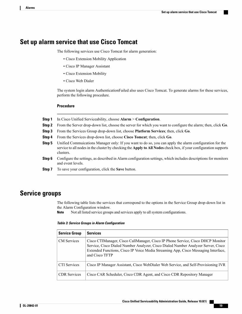
Set up alarm service that use Cisco TomcatThe following services use Cisco Tomcat for alarm generation:
• Cisco Extension Mobility Application
• Cisco IP Manager Assistant
• Cisco Extension Mobility
• Cisco Web Dialer
The system login alarm AuthenticationFailed also uses Cisco Tomcat. To generate alarms for these services,perform the following procedure.
Procedure
Step 1 In Cisco Unified Serviceability, choose Alarm > Configuration.Step 2 From the Server drop-down list, choose the server for which you want to configure the alarm; then, clickGo.Step 3 From the Services Group drop-down list, choose Platform Services; then, click Go.Step 4 From the Services drop-down list, choose Cisco Tomcat; then, click Go.Step 5 Unified Commuications Manager only: If you want to do so, you can apply the alarm configuration for the
service to all nodes in the cluster by checking theApply to All Nodes check box, if your configuration supportsclusters.
Step 6 Configure the settings, as described in Alarm configuration settings, which includes descriptions for monitorsand event levels.
Step 7 To save your configuration, click the Save button.
Service groupsThe following table lists the services that correspond to the options in the Service Group drop-down list inthe Alarm Configuration window.
Not all listed service groups and services apply to all system configurations.Note
Table 3: Service Groups in Alarm Configuration
ServicesService Group
Cisco CTIManager, Cisco CallManager, Cisco IP Phone Service, Cisco DHCP MonitorService, Cisco Dialed Number Analyzer, Cisco Dialed Number Analyzer Server, CiscoExtended Functions, Cisco IP Voice Media Streaming App, Cisco Messaging Interface,and Cisco TFTP
CM Services
Cisco IP Manager Assistant, Cisco WebDialer Web Service, and Self-Provisioning IVRCTI Services
Cisco CAR Scheduler, Cisco CDR Agent, and Cisco CDR Repository ManagerCDR Services
Cisco Unified Serviceability Administration Guide, Release 10.0(1) OL-29842-01 19
AlarmsSet up alarm service that use Cisco Tomcat
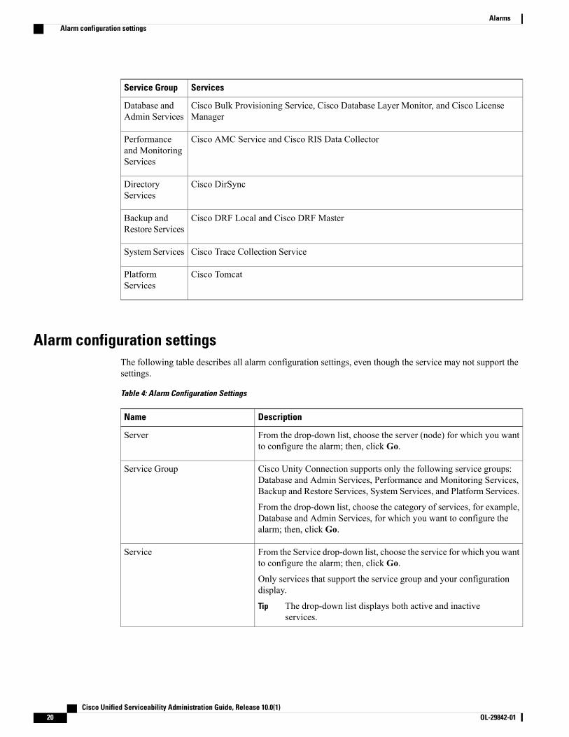
ServicesService Group
Cisco Bulk Provisioning Service, Cisco Database Layer Monitor, and Cisco LicenseManager
Database andAdmin Services
Cisco AMC Service and Cisco RIS Data CollectorPerformanceand MonitoringServices
Cisco DirSyncDirectoryServices
Cisco DRF Local and Cisco DRF MasterBackup andRestore Services
Cisco Trace Collection ServiceSystem Services
Cisco TomcatPlatformServices
Alarm configuration settingsThe following table describes all alarm configuration settings, even though the service may not support thesettings.
Table 4: Alarm Configuration Settings
DescriptionName
From the drop-down list, choose the server (node) for which you wantto configure the alarm; then, click Go.
Server
Cisco Unity Connection supports only the following service groups:Database and Admin Services, Performance and Monitoring Services,Backup and Restore Services, System Services, and Platform Services.
From the drop-down list, choose the category of services, for example,Database and Admin Services, for which you want to configure thealarm; then, click Go.
Service Group
From the Service drop-down list, choose the service for which you wantto configure the alarm; then, click Go.
Only services that support the service group and your configurationdisplay.
The drop-down list displays both active and inactiveservices.
Tip
Service
Cisco Unified Serviceability Administration Guide, Release 10.0(1)20 OL-29842-01
AlarmsAlarm configuration settings

DescriptionName
To apply the alarm settings for the service to all nodes in a cluster, checkthe check box.
Unified CommunicationsManagerandCiscoUnifiedCommunicationsManager IM and Presence Serviceonly:
Apply to All Nodes
The SysLog viewer serves as the alarm destination. The program logserrors in the Application Logs within SysLog Viewer and provides adescription of the alarm and a recommended action. You can access theSysLog Viewer from the Cisco Unified Real-Time Monitoring Tool.
For information on viewing logs with the SysLog Viewer, refer to theCisco Unified Real-Time Monitoring Tool Administration Guide.
Enable Alarm for Local Syslogs
The Syslog file serves as the alarm destination. Check this check boxto enable the Syslog messages to be stored on a Syslog server and tospecify the Syslog server name. If this destination is enabled and noserver name is specified, Cisco Unified Serviceability does not send theSyslog messages.
The configured AMC primary and failover collectors use the remotesyslog settings. The remote syslog settings used by the collectors arethose configured on the respective individual nodes.
If the remote syslog is only configured on AMC primary collectorwithout configuring remote syslog on AMC failover collector andfailover occurs in AMC primary collector, then no remote syslogs willbe generated.
You must configure exactly the same settings on all nodes, to send theremote syslog alarms to the same remote syslog server.
When failover occurs in AMC controller or when the collectorconfiguration changes to a different node, the remote syslog settings ona backup or newly configured node is used.
To prevent too many alarms flooding the system, you can check theExclude End Point Alarms check box. This ensures that the endpointphone-related events get logged into a separate file.
Exclude End Point Alarms check box is displayed only for theCallManager services, and is not checked by default. You need to checkthe Apply to All Nodes also, when you check this check box. Theconfiguration options for endpoint alarms are listed in Alarmconfiguration settings.
Do not specify a Cisco Unified Communications Manager or aCisco Unified Communications Manager IM and PresenceService node as the destination because the node does not acceptsyslog messages from another node.
Tip
Enable Alarm for Remote Syslogs
Cisco Unified Serviceability Administration Guide, Release 10.0(1) OL-29842-01 21
AlarmsAlarm configuration settings

DescriptionName
In each of the Server Name 1, Server Name 2, Server Name 3, ServerName 4, and Server Name 5 fields, enter the name or IP address of theremote syslog server that you want to use to accept syslog messages.For example, if you want to send the alarms to Cisco Unified OperationsManager, specify the Cisco Unified Operations Manager as the servername.
Do not specify a Cisco Unified Communications Manager or aCisco Unified Communications Manager IM and PresenceService node as the destination because the node does not acceptsyslog messages from another node.
Tip
Remote Syslog Servers
The SDI trace library serves as the alarm destination.
To log alarms, check this check box and check the Trace On check boxin the Trace Configuration window for the chosen service. Forinformation on configuring settings in the Trace Configuration windowin Cisco Unified Serviceability, see Set up trace parameters.
Enable Alarm for SDI Trace
The SDL trace library serves as the alarm destination. This destinationapplies only to the Cisco CallManager service and the CTIManagerservice. Configure this alarm destination by using Trace SDLconfiguration. To log alarms in the SDL trace log file, check this checkbox and check the Trace On check box in the Trace Configurationwindow for the chosen service. For information on configuring settingsin the Trace Configuration window in Cisco Unified Serviceability, seethe Set up trace parameters.
Unified CommunicationsManagerand Unified CommunicationsManager BE only:
Enable Alarm for SDL Trace
Cisco Unified Serviceability Administration Guide, Release 10.0(1)22 OL-29842-01
AlarmsAlarm configuration settings

DescriptionName
From the drop-down list, choose one of the following options:
Emergency
This level designates system as unusable.
Alert
This level indicates that immediate action is needed.
Critical
The system detects a critical condition.
Error
This level signifies that error condition exists.
Warning
This level indicates that a warning condition is detected.
Notice
This level designates a normal but significant condition.
Informational
This level designates information messages only.
Debug
This level designates detailed event information that CiscoTechnical Assistance Center engineers use for debugging.
Alarm Event Level
The following tables describe the default alarm configuration settings.
SDL TraceSDI TraceRemote SyslogsLocal Syslogs
CheckedCheckedUncheckedCheckedEnable Alarm
ErrorErrorDisabledErrorAlarm Event Level
Syslog TrapsSyslog Severity andStrangulate Alert
Remote SyslogAlternateSyslog
Local SyslogExclude End PointAlarms
NoNoNoYesNoChecked
YesYesYesYesNoUnchecked
Cisco Unified Serviceability Administration Guide, Release 10.0(1) OL-29842-01 23
AlarmsAlarm configuration settings

Alarm definitions and user-defined description additionsThis section provides procedural information to search, view, and create user information for alarm definitionsthat display in the Serviceability interface.
View alarm definitions and add user-defined descriptionsThis section describes how to search for and view an alarm definitions.
Cisco Unified Communications Manager and Cisco Unity Connection only: You can view Cisco UnityConnection alarm definitions in Cisco Unity Connection Serviceability. You cannot add user-defineddescriptions to alarm definitions in Cisco Unity Connection Serviceability.
Cisco Unity Connection also uses certain alarm definitions in Cisco Unified Serviceability, and they mustbe viewed in Cisco Unified Serviceability. Be aware that alarms that are associated with the catalogs inSystem catalogs are available for viewing.
Tip
Before You Begin
Review the description of alarm definition catalogs.
Procedure
Step 1 Select Alarm > Definitions.Step 2 Perform one of the following actions:
• Select an alarm as follows:
◦Select an alarm catalog from the Find alarms where drop-down list, for example, a SystemAlarmcatalog or IM and Presence alarm catalog.
◦Select the specific catalog name from the Equals drop-down list.
• Enter the alarm name in the Enter Alarm Name field.
Step 3 Select Find.Step 4 Perform one of the following actions if multiple pages of alarm definitions exist:
• To select another page, select the appropriate navigation button at the bottom of the Alarm MessageDefinitions window.
• To change the number of alarms that display in the window, select a different value from the Rows perPage drop-down list.
Step 5 Select the alarm definition for which you want alarm details.Step 6 Enter text in the User Defined Text field if you want to add information to the alarm, and then select Save.
If you add text in the User Defined Text field, you can select Clear All at any time to delete theinformation that you entered.
Tip
Cisco Unified Serviceability Administration Guide, Release 10.0(1)24 OL-29842-01
AlarmsAlarm definitions and user-defined description additions
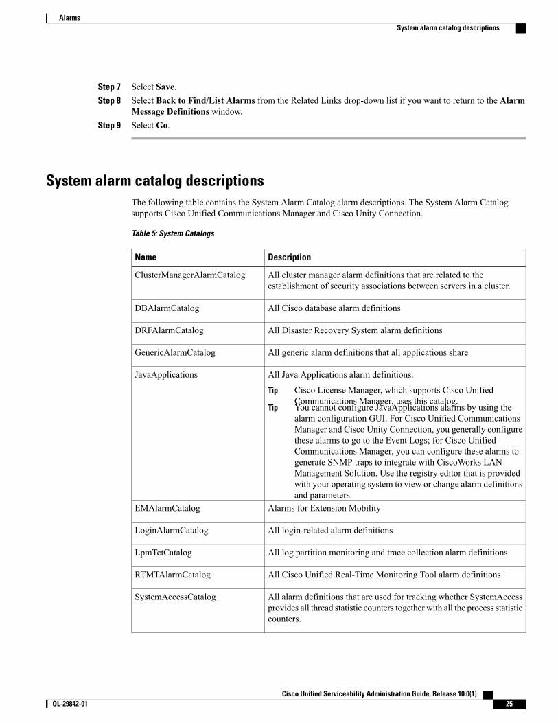
Step 7 Select Save.Step 8 Select Back to Find/List Alarms from the Related Links drop-down list if you want to return to the Alarm
Message Definitions window.Step 9 Select Go.
System alarm catalog descriptionsThe following table contains the System Alarm Catalog alarm descriptions. The System Alarm Catalogsupports Cisco Unified Communications Manager and Cisco Unity Connection.
Table 5: System Catalogs
DescriptionName
All cluster manager alarm definitions that are related to theestablishment of security associations between servers in a cluster.
ClusterManagerAlarmCatalog
All Cisco database alarm definitionsDBAlarmCatalog
All Disaster Recovery System alarm definitionsDRFAlarmCatalog
All generic alarm definitions that all applications shareGenericAlarmCatalog
All Java Applications alarm definitions.
Cisco License Manager, which supports Cisco UnifiedCommunications Manager, uses this catalog.
Tip
You cannot configure JavaApplications alarms by using thealarm configuration GUI. For Cisco Unified CommunicationsManager and Cisco Unity Connection, you generally configurethese alarms to go to the Event Logs; for Cisco UnifiedCommunications Manager, you can configure these alarms togenerate SNMP traps to integrate with CiscoWorks LANManagement Solution. Use the registry editor that is providedwith your operating system to view or change alarm definitionsand parameters.
Tip
JavaApplications
Alarms for Extension MobilityEMAlarmCatalog
All login-related alarm definitionsLoginAlarmCatalog
All log partition monitoring and trace collection alarm definitionsLpmTctCatalog
All Cisco Unified Real-Time Monitoring Tool alarm definitionsRTMTAlarmCatalog
All alarm definitions that are used for tracking whether SystemAccessprovides all thread statistic counters together with all the process statisticcounters.
SystemAccessCatalog
Cisco Unified Serviceability Administration Guide, Release 10.0(1) OL-29842-01 25
AlarmsSystem alarm catalog descriptions

DescriptionName
All service manager alarm definitions that are related to the activation,deactivation, starting, restarting, and stopping of services.
ServiceManagerAlarmCatalogs
All Cisco TFTP alarm definitionsTFTPAlarmCatalog
Alarms for Trust Verification ServiceTVSAlarmCatalog
All alarm definitions that are used for sending test alarms throughSNMP traps from the command line interface (CLI). For informationon the CLI, refer to the Command Line Interface Reference Guide forCisco Unified Solutions.
Cisco Unity Connection SNMP does not support traps in eitherUnified CommunicationsManager and Cisco Unity Connectionsystems.
Tip
TestAlarmCatalog
All certificate expiration definitions.CertMonitorAlarmCatalog
Alarms for Certificate Trust List (CTL) Provider serviceCTLproviderAlarmCatalog
Alarms for Cisco Discovery Protocol (CDP) serviceCDPAlarmCatalog
All user authentication and credential definitions.IMSAlarmCatalog
CallManager alarm catalog descriptionsThe information in this section does not apply to Cisco Unity Connection.
The following table contains the CallManager Alarm Catalog descriptions.
Table 6: CallManager Alarm Catalog
DescriptionName
All Cisco CallManager service alarm definitionsCallManager
All CDRRep alarm definitionsCDRRepAlarmCatalog
All CDR analysis and reporting alarm definitionsCARAlarmCatalog
All Cisco Extended Functions alarm definitionsCEFAlarmCatalog
All Cisco messaging interface alarm definitionsCMIAlarmCatalog
All Cisco computer telephony integration (CTI) manager alarmdefinitions
CtiManagerAlarmCatalog
All IP voice media streaming applications alarm definitionsIpVmsAlarmCatalog
Cisco Unified Serviceability Administration Guide, Release 10.0(1)26 OL-29842-01
AlarmsCallManager alarm catalog descriptions

DescriptionName
All Cisco telephony call dispatcher service alarm definitionsTCDSRVAlarmCatalog
Alarms for phone-related tasks, such as downloadsPhone
Alarms for Certificate Authority Proxy Function (CAPF) serviceCAPFAlarmCatalog
Alarms for SAML Single Sign On feature.SAMLSSOAlarmCatalog
IM and Presence Alarm Catalog descriptionsThe following table contains the IM and Presence Service Alarm Catalog description.
Table 7: IM and Presence Service Alarm Catalog
DescriptionName
All Config Agent alarms that notify the IM and PresenceService SIP Proxy of configuration changes in the IMand Presence Service IDS database.
CiscoUPSConfigAgent
All Intercluster Sync Agent alarms that synchronize enduser information between IM and Presence Serviceclusters for intercluster routing.
CiscoUPInterclusterSyncAgent
All Presence Engine alarms that collect informationregarding the availability status and communicationscapabilities of a user.
CiscoUPSPresenceEngine
All SIP Proxy alarms that are related to routing, requestoridentification, and transport interconnection.
CiscoUPSSIPProxy
All simple object access protocol (SOAP) alarms thatprovide a secure SOAP interface to and from externalclients using HTTPS.
CiscoUPSSOAP
All Sync Agent alarms that keep the IM and PresenceService data synchronized with Cisco UnifiedCommunications Manager data.
CiscoUPSSyncAgent
All XCP alarms that collect information on the status ofXCP components and services on IM and PresenceService.
CiscoUPXCP
All server recovery manager alarms that relate to thefailover and fallback process between nodes in a presenceredundancy group.
CiscoUPServerRecoveryManager
Cisco Unified Serviceability Administration Guide, Release 10.0(1) OL-29842-01 27
AlarmsIM and Presence Alarm Catalog descriptions
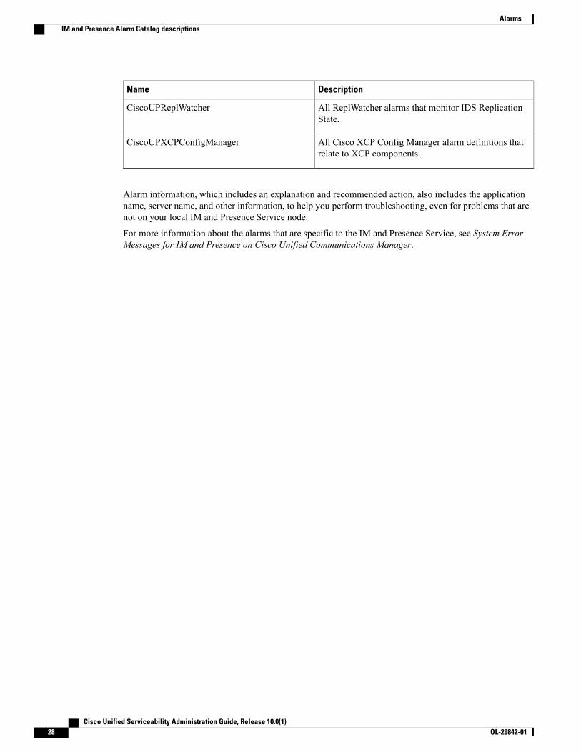
DescriptionName
All ReplWatcher alarms that monitor IDS ReplicationState.
CiscoUPReplWatcher
All Cisco XCP Config Manager alarm definitions thatrelate to XCP components.
CiscoUPXCPConfigManager
Alarm information, which includes an explanation and recommended action, also includes the applicationname, server name, and other information, to help you perform troubleshooting, even for problems that arenot on your local IM and Presence Service node.
For more information about the alarms that are specific to the IM and Presence Service, see System ErrorMessages for IM and Presence on Cisco Unified Communications Manager.
Cisco Unified Serviceability Administration Guide, Release 10.0(1)28 OL-29842-01
AlarmsIM and Presence Alarm Catalog descriptions

C H A P T E R 4Trace
• Trace, page 29
• Configure trace, page 32
TraceCisco Unified Serviceability provides trace tools to assist you in troubleshooting issues with your voiceapplication. Cisco Unified Serviceability supports SDI (System Diagnostic Interface) trace, SDL (SignalingDistribution Layer) trace (for Cisco CallManager and Cisco CTIManager services, applicable to Cisco UnifiedCommunications Manager only), and Log4J trace (for Java applications).
You use the Trace Configuration window to specify the level of information that you want traced as well thetype of information that you want to be included in each trace file.
Cisco Unified Communications Manager only: If the service is a call-processing application such as CiscoCallManager or Cisco CTIManager, you can configure a trace on devices such as phones and gateway.
Cisco Unified Communications Manager only: In the Alarm Configuration window, you can direct alarms tovarious locations, including SDL trace log files. If you want to do so, you can configure trace for alerts in theCisco Unified Real-Time Monitoring Tool (Unified RTMT).
After you have configured information that you want to include in the trace files for the various services, youcan collect and view trace files by using the Trace and Log Central option in the Cisco Unified Real-TimeMonitoring Tool.
Cisco Unified IM and Presence Serviceability provides trace tools to assist you in troubleshooting issues withyour instant messaging and presence application. Cisco Unified IM and Presence Serviceability supports:
• SDI trace
• Log4J trace (for Java applications)
You can configure the level of information that you want traced (debug level), what information you want totrace (trace fields), and information about the trace files (such as number of files per service, size of file, andtime that the data is stored in the trace files). You can configure trace for a single service or apply the tracesettings for that service to all servers in the cluster.
In the Alarm Configuration window, you can direct alarms to various locations. If you want to do so, youcan configure trace for alerts in the IM and Presence Unified RTMT.
Cisco Unified Serviceability Administration Guide, Release 10.0(1) OL-29842-01 29

After you have configured information that you want to include in the trace files for the various services, youcan collect and view trace files by using the Trace and Log Central option in the Unified RTMT. You canconfigure trace parameters for any feature or network service that is available on any IM and Presence nodein the cluster. Use the Trace Configuration window to specify the parameters that you want to trace fortroubleshooting problems. If you want to use predetermined troubleshooting trace settings rather than choosingyour own trace fields, you can use the Troubleshooting Trace Setting window.
Enabling Trace decreases system performance; therefore, enable Trace only for troubleshooting purposes.For assistance in using Trace, contact Cisco Technical Assistance Center (TAC).
Note
Trace configurationYou can configure trace parameters for any feature or network service that displays in the Serviceabilityinterface. If you have clusters, you can configure trace parameters for any feature or network service that isavailable on any server in the cluster. Use the Trace Configuration window to specify the parameters that youwant to trace for troubleshooting problems.
You can configure the level of information that you want traced (debug level), what information you want totrace (trace fields), and information about the trace files (such as number of files per service, size of file, andtime that the data is stored in the trace files). If you have clusters, you can configure trace for a single serviceor apply the trace settings for that service to all servers in the cluster.
If you want to use predetermined troubleshooting trace settings rather than choosing your own trace fields,you can use the Troubleshooting Trace window. For more information on troubleshooting trace, see Tracesettings.
After you have configured information that you want to include in the trace files for the various services, youcan collect trace files by using the trace and log central option in Unified RTMT. For more informationregarding trace collection, see Trace collection.
Trace settingsThe Troubleshooting Trace Settings window allows you to choose the services for which you want to setpredetermined troubleshooting trace settings. In this window, you can choose a single service or multipleservices and change the trace settings for those services to the predetermined trace settings. If you have clusters,you can choose the services on different servers in the cluster, so the trace settings of the chosen services getchanged to the predetermined trace settings. You can choose specific activated services for a single server,all activated services for the server, specific activated services for all servers in the cluster, or all activatedservices for all servers in the cluster. In the window, N/A displays next to inactive services.
The predetermined troubleshooting trace settings for a feature or network service include SDL, SDI, andLog4j trace settings. Before the troubleshooting trace settings are applied, the system backs up the originaltrace settings. When you reset the troubleshooting trace settings, the original trace settings are restored.
Note
When you open the Troubleshooting Trace Settings window after you apply troubleshooting trace settings toa service, the service that you set for troubleshooting displays as checked. In the Troubleshooting TraceSettings window, you can reset the trace settings to the original settings.
Cisco Unified Serviceability Administration Guide, Release 10.0(1)30 OL-29842-01
TraceTrace configuration

After you apply Troubleshooting Trace Setting to a service, the Trace Configuration window displays amessage that troubleshooting trace is set for that service. From the Related Links drop-down list box, you canchoose the Troubleshooting Trace Settings option if you want to reset the settings for the service. For thegiven service, the Trace Configuration window displays all the settings as read-only, except for some parametersof trace output settings, for example, Maximum No. of Files. You can modify these parameters even afteryou apply troubleshooting trace settings.
Trace collectionUse Trace and Log Central, an option in the Cisco Unified Real-Time Monitoring Tool, to collect, view, andzip various service traces or other log files. With the Trace and Log Central option, you can collect SDL/SDItraces, Application Logs, System Logs (such as Event View Application, Security, and System logs), andcrash dump files.
Do not use Windows NotePad to view collected trace files to view collected trace files, because WindowsNotePad does not properly display line breaks.
Tip
Cisco Unified Communications Manager only: For devices that support encryption, the Secure Real-timeTransport Protocol (SRTP) keying material does not display in the trace file.
Note
For more information about trace collection, see Cisco Unified Real-Time Monitoring Tool AdministrationGuide.
Called Party TracingCalled Party Tracing allows you to configure a directory number or list of directory numbers that you wantto trace. You can request on-demand tracing of calls using the Session Trace Tool.
For more information, see the Cisco Unified Real-Time Monitoring Tool Administration Guide.
Set up trace configurationThe following procedure provides an overview of the steps to configure and collect trace for feature andnetwork services in the Serviceability interface.
Procedure
Step 1 Configure the values of the TLC Throttling CPU Goal and TLC Throttling IOWait Goal service parameters(Cisco RIS Data Collector service) by performing one of these steps:
• Cisco Unified Communications Manager Administration and Cisco Unified IM and Presense: SelectSystem > ServiceParameters and configure the values of the TLC Throttling CPU Goal and TLCThrottling IOWait Goal service parameters (Cisco RIS Data Collector service).
Cisco Unified Serviceability Administration Guide, Release 10.0(1) OL-29842-01 31
TraceTrace collection
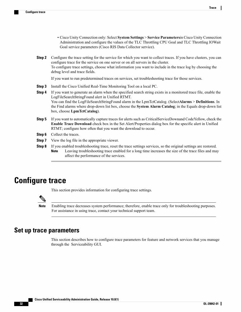
• Cisco Unity Connection only: Select System Settings > Service Parametersin Cisco Unity ConnectionAdministration and configure the values of the TLC Throttling CPU Goal and TLC Throttling IOWaitGoal service parameters (Cisco RIS Data Collector service).
Step 2 Configure the trace setting for the service for which you want to collect traces. If you have clusters, you canconfigure trace for the service on one server or on all servers in the cluster.To configure trace settings, choose what information you want to include in the trace log by choosing thedebug level and trace fields.
If you want to run predetermined traces on services, set troubleshooting trace for those services.
Step 3 Install the Cisco Unified Real-Time Monitoring Tool on a local PC.Step 4 If you want to generate an alarm when the specified search string exists in a monitored trace file, enable the
LogFileSearchStringFound alert in Unified RTMT.You can find the LogFileSearchStringFound alarm in the LpmTctCatalog. (SelectAlarms > Definitions. Inthe Find alarms where drop-down list box, choose the System Alarm Catalog; in the Equals drop-down listbox, choose LpmTctCatalog).
Step 5 If you want to automatically capture traces for alerts such as CriticalServiceDownand CodeYellow, check theEnable Trace Download check box in the Set Alert/Properties dialog box for the specific alert in UnifiedRTMT; configure how often that you want the download to occur.
Step 6 Collect the traces.Step 7 View the log file in the appropriate viewer.Step 8 If you enabled troubleshooting trace, reset the trace settings services, so the original settings are restored.
Leaving troubleshooting trace enabled for a long time increases the size of the trace files and mayaffect the performance of the services.
Note
Configure traceThis section provides information for configuring trace settings.
Enabling trace decreases system performance; therefore, enable trace only for troubleshooting purposes.For assistance in using trace, contact your technical support team.
Note
Set up trace parametersThis section describes how to configure trace parameters for feature and network services that you managethrough the Serviceability GUI.
Cisco Unified Serviceability Administration Guide, Release 10.0(1)32 OL-29842-01
TraceConfigure trace

For Cisco Unity Connection, you may need to run trace in Cisco Unified Serviceability and Cisco UnityConnection Serviceability to troubleshoot Cisco Unity Connection issues. For information on how to runtrace in Cisco Unity Connection Serviceability, refer to the Cisco Unity Connection ServiceabilityAdministration Guide .
Tip
Procedure
Step 1 Select Trace > Configuration.The Trace Configuration window displays.
Step 2 From the Server drop-down list box, select the server that is running the service for which you want to configuretrace; then, click Go.
Step 3 From the Service Group drop-down list box, select the service group for the service that you want to configuretrace; then, click Go.
The Service Groups in Trace Configuration table lists the services and trace libraries that correspondto the options that display in the Service Group drop-down list box.
Tip
Step 4 From the Service drop-down list box, select the service for which you want to configure trace and, click Go.The drop-down list box displays active and inactive services.
Cisco Unity Connection only: For the Cisco CallManager and CTIManager services, you can configureSDL trace parameters. To do so, open the Trace Configuration window for one of those services, andclick the Go button that is next to the Related Links drop-down list box.
Tip
If you configured Troubleshooting Trace for the service, a message displays at the top of the window thatindicates that the Troubleshooting Traces feature is set, which means that the system disables all fields in theTrace Configuration window except for Trace Output Settings. To configure the Trace Output Settings, goto Step 11. To reset Troubleshooting Trace, see the Set up troubleshooting trace settings.
The trace parameters display for the service that you chose. In addition, the Apply to All Nodes check boxdisplays (Cisco Unified Communications Manager only).
Step 5 Unified Communications Manager and IM and Presence only: If you want to do so, you can apply the tracesettings for the service or trace library to all servers in the cluster by checking the Apply to All Nodes checkbox; that is, if your configuration supports clusters.
Step 6 Check the Trace On check box.Step 7 Cisco Unity Connection only: If you are configuring SDL trace parameters, go to Step 10.Step 8 Select the level of information that you want traced from the Debug Trace Level list box, as described in
Debug trace level settings.Step 9 Check theTrace Fields check box for the service that you chose, for example, Cisco Log PartitionMonitoring
Tool Trace Fields.Step 10 If the service does not have multiple trace settings where you can specify the traces that you want to activate,
check the Enable All Trace check box. If the service that you chose has multiple trace settings, check thecheck boxes next to the trace check boxes that you want to enable, as described in Trace field descriptions.
Step 11 To limit the number and size of the trace files, specify the trace output setting. See Trace Ouput Settings fordescriptions.
Step 12 To save your trace parameters configuration, click the Save button.The changes to trace configuration take effect immediately for all services except Cisco Messaging Interface(Cisco Unified CommunicationsManager only). The trace configuration changes for CiscoMessaging Interfacetake effect in 3 to 5 minutes.
Cisco Unified Serviceability Administration Guide, Release 10.0(1) OL-29842-01 33
TraceSet up trace parameters

To set the default, click the Set Defaultbutton.
Note
Service groups in trace configurationThe following table lists the services and trace libraries that correspond to the options in the Service Groupdrop-down list box in the Trace Configuration window.
Table 8: Service Groups in Trace Configuration
NotesServices and Trace LibrariesService Group
For most services in the CMServices group, yourun trace for specific components, instead ofenabling all trace for the service. The Trace fielddescriptions lists the services for which you canrun trace for specific components.
• Cisco CTIManager
• Cisco CallManager
• Cisco CallManager Cisco IPPhone Service
• Cisco DHCP Monitor Service
• CiscoDialedNumberAnalyzer
• CiscoDialedNumberAnalyzerServer
• Cisco Extended Functions,Cisco Extension Mobility
• Cisco Extension MobilityApplication
• Cisco IP Voice MediaStreaming App
• Cisco Messaging Interface
• Cisco TFTP
• Cisco Unified Mobile VoiceAccess Service
Cisco UnifiedCommunicationsManager
CM Services
For these services, you can run trace for specificcomponents, instead of enabling all trace for theservice; see the Trace field descriptions.
• Cisco IP Manager Assistant
• CiscoWebDialerWeb Service
Cisco UnifiedCommunicationsManager
CTI Services
Cisco Unified Serviceability Administration Guide, Release 10.0(1)34 OL-29842-01
TraceService groups in trace configuration

NotesServices and Trace LibrariesService Group
You enable all trace for each service, instead ofrunning trace for specific components.
In Cisco Unified Communications ManagerCDR Analysis and Reporting, when reports arerun that call stored procedures, UnifiedCommunications Manager CDR Analysis andReporting checks the configured debug tracelevel for the Unified Communications ManagerCDR Analysis and Reporting Scheduler serviceand the Unified CommunicationsManager CDRAnalysis and ReportingWeb Service in the TraceConfiguration window before stored procedurelogging begins. For pregenerated reports, UnifiedCommunications Manager CDR Analysis andReporting checks the level for the UnifiedCommunications Manager CDR Analysis andReporting Scheduler service; for on-demandreports, Unified CommunicationsManager CDRAnalysis and Reporting checks the level for theCisco Unified Communications Manager CDRAnalysis and Reporting Web Service. If youchoose Debug from the Debug Trace Leveldrop-down list box, stored procedure logginggets enabled and continues until you chooseanother option from the drop-down list box. Thefollowing Unified Communications ManagerCDR Analysis and Reporting reports use storedprocedure logging: Gateway Utilization report,Route and Line Group Utilization report,Route/Hunt List Utilization report, RoutePattern/Hunt Pilot Utilization report, ConferenceCall Details report, Conference Call Summaryreport, Conference Bridge Utilization report,Voice Messaging Utilization report, and theCDR Search report.
• Cisco UnifiedCommunications ManagerCDR Analysis and ReportingScheduler
• Cisco UnifiedCommunications ManagerCDR Analysis and ReportingWeb Service
• Cisco CDR Agent
• Cisco CDR RepositoryManager
Cisco UnifiedCommunicationsManager
CDR Services
Cisco Unified Serviceability Administration Guide, Release 10.0(1) OL-29842-01 35
TraceService groups in trace configuration
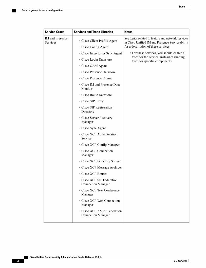
NotesServices and Trace LibrariesService Group
See topics related to feature and network servicesin Cisco Unified IM and Presence Serviceabilityfor a description of these services.
• For these services, you should enable alltrace for the service, instead of runningtrace for specific components.
• Cisco Client Profile Agent
• Cisco Config Agent
• Cisco Intercluster Sync Agent
• Cisco Login Datastore
• Cisco OAM Agent
• Cisco Presence Datastore
• Cisco Presence Engine
• Cisco IM and Presence DataMonitor
• Cisco Route Datastore
• Cisco SIP Proxy
• Cisco SIP RegistrationDatastore
• Cisco Server RecoveryManager
• Cisco Sync Agent
• Cisco XCP AuthenticationService
• Cisco XCP Config Manager
• Cisco XCP ConnectionManager
• Cisco XCP Directory Service
• Cisco XCP Message Archiver
• Cisco XCP Router
• Cisco XCP SIP FederationConnection Manager
• Cisco XCP Text ConferenceManager
• Cisco XCP Web ConnectionManager
• Cisco XCP XMPP FederationConnection Manager
IM and PresenceServices
Cisco Unified Serviceability Administration Guide, Release 10.0(1)36 OL-29842-01
TraceService groups in trace configuration
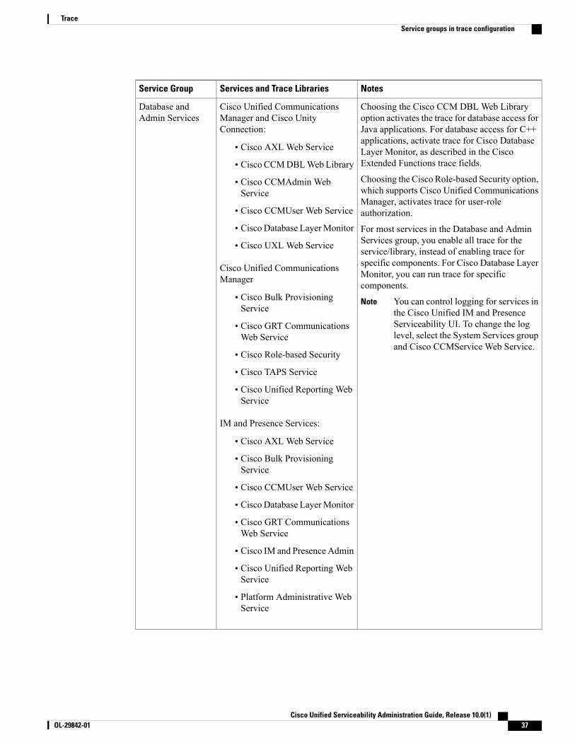
NotesServices and Trace LibrariesService Group
Choosing the Cisco CCM DBL Web Libraryoption activates the trace for database access forJava applications. For database access for C++applications, activate trace for Cisco DatabaseLayer Monitor, as described in the CiscoExtended Functions trace fields.
Choosing the Cisco Role-based Security option,which supports Cisco Unified CommunicationsManager, activates trace for user-roleauthorization.
For most services in the Database and AdminServices group, you enable all trace for theservice/library, instead of enabling trace forspecific components. For Cisco Database LayerMonitor, you can run trace for specificcomponents.
You can control logging for services inthe Cisco Unified IM and PresenceServiceability UI. To change the loglevel, select the System Services groupand Cisco CCMService Web Service.
Note
Cisco Unified CommunicationsManager and Cisco UnityConnection:
• Cisco AXL Web Service
• Cisco CCMDBLWeb Library
• Cisco CCMAdmin WebService
• Cisco CCMUser Web Service
• Cisco Database LayerMonitor
• Cisco UXL Web Service
Cisco Unified CommunicationsManager
• Cisco Bulk ProvisioningService
• Cisco GRT CommunicationsWeb Service
• Cisco Role-based Security
• Cisco TAPS Service
• Cisco Unified Reporting WebService
IM and Presence Services:
• Cisco AXL Web Service
• Cisco Bulk ProvisioningService
• Cisco CCMUser Web Service
• Cisco Database LayerMonitor
• Cisco GRT CommunicationsWeb Service
• Cisco IM and Presence Admin
• Cisco Unified Reporting WebService
• Platform Administrative WebService
Database andAdmin Services
Cisco Unified Serviceability Administration Guide, Release 10.0(1) OL-29842-01 37
TraceService groups in trace configuration
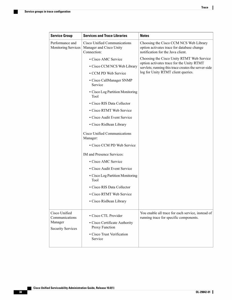
NotesServices and Trace LibrariesService Group
Choosing the Cisco CCM NCS Web Libraryoption activates trace for database changenotification for the Java client.
Choosing the Cisco Unity RTMT Web Serviceoption activates trace for the Unity RTMTservlets; running this trace creates the server-sidelog for Unity RTMT client queries.
Cisco Unified CommunicationsManager and Cisco UnityConnection:
• Cisco AMC Service
• Cisco CCMNCSWeb Library
• CCM PD Web Service
• Cisco CallManager SNMPService
• Cisco Log PartitionMonitoringTool
• Cisco RIS Data Collector
• Cisco RTMT Web Service
• Cisco Audit Event Service
• Cisco RisBean Library
Cisco Unified CommunicationsManager:
• Cisco CCM PD Web Service
IM and Presence Services:
• Cisco AMC Service
• Cisco Audit Event Service
• Cisco Log PartitionMonitoringTool
• Cisco RIS Data Collector
• Cisco RTMT Web Service
• Cisco RisBean Library
Performance andMonitoring Services
You enable all trace for each service, instead ofrunning trace for specific components.• Cisco CTL Provider
• Cisco Certificate AuthorityProxy Function
• Cisco Trust VerificationService
Cisco UnifiedCommunicationsManager
Security Services
Cisco Unified Serviceability Administration Guide, Release 10.0(1)38 OL-29842-01
TraceService groups in trace configuration

NotesServices and Trace LibrariesService Group
You enable all trace for this service, instead ofrunning trace for specific components.
Cisco DirSyncCisco UnifiedCommunicationsManager
Directory Services
You enable all trace for each service, instead ofrunning trace for specific components.• Cisco DRF Local
• Cisco UnifiedCommunicationsManager andCisco Unity Connection only:Cisco DRF Master
Backup and RestoreServices
Choosing the Cisco CCMRealm Web Serviceoption activates trace for login authentication.
Choosing the Cisco Common User Interfaceoption activates trace for the common code thatmultiple applications use; for example, CiscoUnified Operating System Administration andCisco Unified Serviceability.
Choosing the Cisco CCMService Web Serviceoption activates trace for the Cisco UnifiedServiceability web application (GUI).
You enable all trace for each option/service,instead of running trace for specific components.
Cisco Unified CommunicationsManager:
• Cisco CCMRealm WebService
• Cisco CCMService WebService
• Cisco Common User Interface
• Cisco Trace Collection Service
IM and Presence Services:
• Cisco CCMService WebService
• Cisco Trace Collection Service
System Services
Choosing the Cisco SOAP Web Service optionactivates the trace for the AXL ServiceabilityAPI.
You enable all trace for this service, instead ofrunning trace for specific components.
• Cisco SOAP Web Service
• Cisco SOAPMessage Service
SOAP Services
The Cisco Unified OS Admin Web Servicesupports Cisco Unified Operating SystemAdministration, which is the web applicationthat provides management of platform-relatedfunctionality such as certificate management,version settings, and installations and upgrades.
You enable all trace for this service, instead ofrunning trace for specific components.
Cisco Unified OS Admin WebService
Platform Services
Cisco Unified Serviceability Administration Guide, Release 10.0(1) OL-29842-01 39
TraceService groups in trace configuration
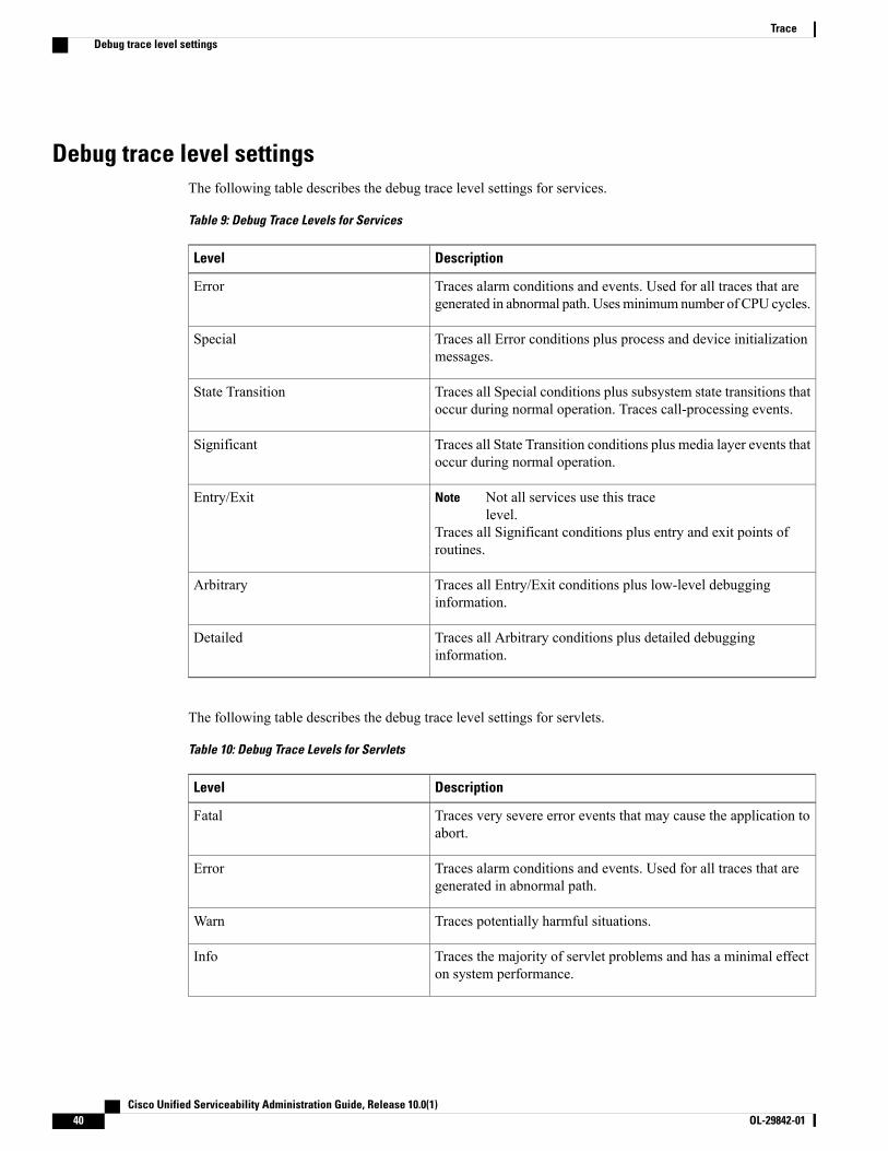
Debug trace level settingsThe following table describes the debug trace level settings for services.
Table 9: Debug Trace Levels for Services
DescriptionLevel
Traces alarm conditions and events. Used for all traces that aregenerated in abnormal path. Usesminimumnumber of CPU cycles.
Error
Traces all Error conditions plus process and device initializationmessages.
Special
Traces all Special conditions plus subsystem state transitions thatoccur during normal operation. Traces call-processing events.
State Transition
Traces all State Transition conditions plus media layer events thatoccur during normal operation.
Significant
Not all services use this tracelevel.
Note
Traces all Significant conditions plus entry and exit points ofroutines.
Entry/Exit
Traces all Entry/Exit conditions plus low-level debugginginformation.
Arbitrary
Traces all Arbitrary conditions plus detailed debugginginformation.
Detailed
The following table describes the debug trace level settings for servlets.
Table 10: Debug Trace Levels for Servlets
DescriptionLevel
Traces very severe error events that may cause the application toabort.
Fatal
Traces alarm conditions and events. Used for all traces that aregenerated in abnormal path.
Error
Traces potentially harmful situations.Warn
Traces the majority of servlet problems and has a minimal effecton system performance.
Info
Cisco Unified Serviceability Administration Guide, Release 10.0(1)40 OL-29842-01
TraceDebug trace level settings

DescriptionLevel
Traces all State Transition conditions plus media layer events thatoccur during normal operation.
Trace level that turns on all logging.
Debug
Trace field descriptionsFor some services, you can activate trace for specific components, instead of enabling all trace for the service.The following list includes the services for which you can activate trace for specific components. Clickingone of the cross-references takes you to the applicable section where a description displays for each trace fieldfor the service. If a service does not exist in the following list, the Enable All Trace check box displays forthe service in the Trace Configuration window.
The following services are applicable to Cisco Unified CommunicationsManager and Cisco Unity Connection:
• Database layer monitor trace fields
• Cisco RIS data collector trace fields
The following services are applicable to Cisco Unified Communications Manager:
• Cisco CallManager SDI trace fields
• Cisco CallManager SDL trace fields
• Cisco CTIManager SDL trace fields
• Cisco Extended Functions trace fields
• Cisco Extension Mobility trace fields
• Cisco IP manager assistant trace fields
• Cisco IP voice media streaming app trace fields
• Cisco TFTP trace fields
• Cisco Web Dialer web service trace fields
Database layer monitor trace fieldsThe following table describes the Cisco Database Layer Monitor trace fields. The Cisco Database LayerMonitor service supports Cisco Unified Communications Manager and Cisco Unity Connection.
Table 11: Cisco Database Layer Monitor Trace Fields
DescriptionField Name
Activates database library trace for C++ applications.Enable DB Library Trace
Activates service trace.Enable Service Trace
Cisco Unified Serviceability Administration Guide, Release 10.0(1) OL-29842-01 41
TraceTrace field descriptions

DescriptionField Name
Activates the database change notification traces forC++ applications.
Enable DB Change Notification Trace
Do not check this check box. Cisco engineering usesit for debugging purposes.
Enable Unit Test Trace
Cisco RIS data collector trace fieldsThe following table describes the Cisco RIS Data Collector trace fields. The Cisco RIS Data Collector servicesupports Cisco Unified Communications Manager and Cisco Unity Connection.
Table 12: Cisco RIS Data Collector Trace Fields
DescriptionField Name
Activates trace for the RISDC thread of the RIS datacollector service (RIS).
Enable RISDC Trace
Activates trace for the system access library in theRIS data collector.
Enable System Access Trace
Activates trace for the link services library in the RISdata collector.
Enable Link Services Trace
Activates trace for the RISDC access library in theRIS data collector.
Enable RISDC Access Trace
Activates trace for the RISDB library in the RIS datacollector.
Enable RISDB Trace
Activates trace for the PI library in the RIS datacollector.
Enable PI Trace
Activates trace for the input/output XML messagesof the RIS data collector service.
Enable XML Trace
Activates trace for the troubleshooting perfmon datalogging in the RIS data collector. Used to trace thename of the log file, the total number of counters thatare logged, the names of the application and systemcounters and instances, calculation of process andthread CPU percentage, and occurrences of log filerollover and deletion.
Enable Perfmon Logger Trace
Cisco Unified Serviceability Administration Guide, Release 10.0(1)42 OL-29842-01
TraceTrace field descriptions

Cisco CallManager SDI trace fieldsThe following table describes the Cisco CallManager SDI trace fields. The Cisco CallManager service supportsCisco Unified Communications Manager.
Table 13: Cisco CallManager SDI Trace Fields
DescriptionField Name
Activates trace of H245 messages.Enable H245 Message Trace
Activates the logging of ISDN type ofDT-24+/DE-30+ device traces.
Enable DT-24+/DE-30+ Trace
Activates trace of primary rate interface (PRI) devices.Enable PRI Trace
Activates ISDN message traces. Used for normaldebugging.
Enable ISDN Translation Trace
Activates trace of H.225 devices. Used for normaldebugging.
Enable H225 & Gatekeeper Trace
Activates trace of miscellaneous devices.
Do not check this check box during normalsystem operation.
Note
Enable Miscellaneous Trace
Activates trace of conference bridges. Used fornormal debugging.
Enable Conference Bridge Trace
Activates trace of music on hold (MOH) devices.Used to trace MOH device status such as registeredwith Cisco Unified Communications Manager,unregistered with Cisco Unified CommunicationsManager, and resource allocation processedsuccessfully or failed.
Enable Music on Hold Trace
Activates Cisco Unified Communications Managerreal-time information traces that the real-timeinformation server uses.
Enable Unified CM Real-Time Information ServerTrace
Activates trace of SIP stack. The default is enabled.Enable SIP Stack Trace
Activates trace for the annunciator, a SCCP devicethat uses the Cisco IP Voice Media StreamingApplication service to enable Cisco UnifiedCommunications Manager to play prerecordedannouncements (.wav files) and tones toCisco Unified IP Phones, gateways, and otherconfigurable devices.
Enable Annunciator Trace
Cisco Unified Serviceability Administration Guide, Release 10.0(1) OL-29842-01 43
TraceTrace field descriptions
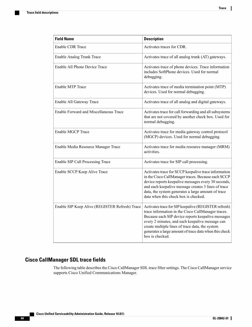
DescriptionField Name
Activates traces for CDR.Enable CDR Trace
Activates trace of all analog trunk (AT) gateways.Enable Analog Trunk Trace
Activates trace of phone devices. Trace informationincludes SoftPhone devices. Used for normaldebugging.
Enable All Phone Device Trace
Activates trace of media termination point (MTP)devices. Used for normal debugging.
Enable MTP Trace
Activates trace of all analog and digital gateways.Enable All Gateway Trace
Activates trace for call forwarding and all subsystemsthat are not covered by another check box. Used fornormal debugging.
Enable Forward and Miscellaneous Trace
Activates trace for media gateway control protocol(MGCP) devices. Used for normal debugging.
Enable MGCP Trace
Activates trace for media resource manager (MRM)activities.
Enable Media Resource Manager Trace
Activates trace for SIP call processing.Enable SIP Call Processing Trace
Activates trace for SCCP keepalive trace informationin the Cisco CallManager traces. Because each SCCPdevice reports keepalive messages every 30 seconds,and each keepalive message creates 3 lines of tracedata, the system generates a large amount of tracedata when this check box is checked.
Enable SCCP Keep Alive Trace
Activates trace for SIP keepalive (REGISTER refresh)trace information in the Cisco CallManager traces.Because each SIP device reports keepalive messagesevery 2 minutes, and each keepalive message cancreate multiple lines of trace data, the systemgenerates a large amount of trace data when this checkbox is checked.
Enable SIP Keep Alive (REGISTER Refresh) Trace
Cisco CallManager SDL trace fieldsThe following table describes the Cisco CallManager SDL trace filter settings. The Cisco CallManager servicesupports Cisco Unified Communications Manager.
Cisco Unified Serviceability Administration Guide, Release 10.0(1)44 OL-29842-01
TraceTrace field descriptions

Cisco recommends that you use the defaults unless a Cisco engineer instructs you to do otherwise.Note
Table 14: Cisco CallManager SDL Configuration Trace Filter Settings
DescriptionSetting Name
Activates traces for Layer 1.Enable all Layer 1 traces.
Activates detailed Layer 1 traces.Enable detailed Layer 1 traces.
Activates traces for Layer 2.Enable all Layer 2 traces.
Activates Layer 2 interface traces.Enable Layer 2 interface trace.
Activates Layer 2 Transmission Control Program(TCP) traces.
Enable Layer 2 TCP trace.
Activates detailed traces for dump Layer 2.Enable detailed dump Layer 2 trace.
Activates traces for Layer 3.Enable all Layer 3 traces.
Activates traces for call control.Enable all call control traces.
Activates traces for miscellaneous polls.Enable miscellaneous polls trace.
Activates miscellaneous traces such as databasesignals.
Enable miscellaneous trace (database signals).
Activates traces for message translation signals.Enable message translation signals trace.
Activates traces for user-to-user informational element(UUIE) output.
Enable UUIE output trace.
Activates traces for gateway signals.Enable gateway signals trace.
Activates CTI trace.Enable CTI trace.
Activates network service data trace.Enable network service data trace
Activates network service event trace.Enable network service event trace
Activates ICCP administration trace.Enable ICCP admin trace
Activates default trace.Enable default trace
The following table describes the Cisco CallManager SDL configuration characteristics.
Cisco Unified Serviceability Administration Guide, Release 10.0(1) OL-29842-01 45
TraceTrace field descriptions

Table 15: Cisco CallManager SDL Configuration Trace Characteristics
DescriptionCharacteristics
Activates trace for intracluster communicationprotocol (ICCP) link state.
Enable SDL link states trace.
Activates trace for low-level SDL.Enable low-level SDL trace.
Activates trace for ICCP link poll.Enable SDL link poll trace.
Activates trace for ICCP raw messages.Enable SDL link messages trace.
Activates traces for signal data dump.Enable signal data dump trace.
Activates traces for correlation tag mapping.Enable correlation tag mapping trace.
Activates traces for SDL process states.Enable SDL process states trace.
Disables trace for pretty print of SDL. Pretty printadds tabs and spaces in a trace file without performingpost processing.
Disable pretty print of SDL trace.
Activates SDL TCP event trace.Enable SDL TCP event trace.
Cisco CTIManager SDL trace fieldsThe following table describes the Cisco CTIManager SDL configuration trace filter settings. The CiscoCTIManager service supports Cisco Unified Communications Manager.
Cisco recommends that you use the defaults unless a Cisco engineer instructs you to do otherwise.Tip
When you choose the CTIManager service from the Service Groups drop-down list box, the TraceConfiguration window displays for SDI traces for this service. To activate SDI trace for the Cisco CTIManager service, check the Enable All Trace check box in the Trace Configuration window for the CiscoCTIManager service. To access the SDL Configuration window, choose SDL Configuration from theRelated Links drop-down list box; the settings that are described in Cisco CTIManager SDL ConfigurationTrace Filter Settings table and Cisco CTIManager SDL Configuration Trace Characteristics table display.
Tip
Table 16: Cisco CTIManager SDL Configuration Trace Filter Settings
DescriptionSetting Name
Activates traces for miscellaneous polls.Enable miscellaneous polls trace.
Cisco Unified Serviceability Administration Guide, Release 10.0(1)46 OL-29842-01
TraceTrace field descriptions

DescriptionSetting Name
Activates miscellaneous traces such as databasesignals.
Enable miscellaneous trace (database signals).
Activates CTI trace.Enable CTI trace.
Activates network service data trace.Enable Network Service Data Trace
Activates network service event trace.Enable Network Service Event Trace
Activates ICCP administration trace.Enable ICCP Admin Trace
Activates default trace.Enable Default Trace
The following table describes the Cisco CTIManager SDL configuration trace characteristics.
Table 17: Cisco CTIManager SDL Configuration Trace Characteristics
DescriptionCharacteristics
Activates trace for ICCP link state.Enable SDL link states trace.
Activates trace for low-level SDL.Enable low-level SDL trace.
Activates trace for ICCP link poll.Enable SDL link poll trace.
Activates trace for ICCP raw messages.Enable SDL link messages trace.
Activates traces for signal data dump.Enable signal data dump trace.
Activates traces for correlation tag mapping.Enable correlation tag mapping trace.
Activates traces for SDL process states.Enable SDL process states trace.
Disables trace for pretty print of SDL. Pretty printadds tabs and spaces in a trace file without performingpost processing.
Disable pretty print of SDL trace.
Activates SDL TCP event trace.Enable SDL TCP Event trace
Cisco Extended Functions trace fieldsThe following table describes the Cisco Extended Functions trace fields. The Cisco Extended Functions servicesupports Cisco Unified Communications Manager.
Cisco Unified Serviceability Administration Guide, Release 10.0(1) OL-29842-01 47
TraceTrace field descriptions

Table 18: Cisco Extended Functions Trace Fields
DescriptionField Name
Activates telephony service provider trace.Enable QBE Helper TSP Trace
Activates QBE helper TSP interface trace.Enable QBE Helper TSPI Trace
Activates quality report tool service dictionary trace.Enable QRT Dictionary Trace
Activates DOM helper trace.Enable DOM Helper Traces
Activates database change notification trace.Enable Redundancy and Change Notification Trace
Activates quality report tool report handler trace.Enable QRT Report Handler Trace
Activates QBE helper CTI trace.Enable QBE Helper CTI Trace
Activates quality report tool service related trace.Enable QRT Service Trace
Activates QRT DB access trace.Enable QRT DB Traces
Activates standard template map andmultimap trace.Enable Template Map Traces
Activates quality report tool event handler trace.Enable QRT Event Handler Trace
Activates quality report tool real-time informationserver trace.
Enable QRT Real-Time Information Server Trace
Cisco Extension Mobility trace fieldsThe following table describes the Cisco ExtensionMobility trace fields. The Cisco ExtensionMobility servicesupports Cisco Unified Communications Manager.
Table 19: Cisco Extension Mobility Trace Fields
DescriptionField Name
Activates trace for the extension mobility service.Enable EM Service Trace
When you activate trace for the Cisco Extension Mobility Application service, you check the Enable AllTrace check box in the Trace Configuration window for the Cisco ExtensionMobility Application service.
Tip
Cisco Unified Serviceability Administration Guide, Release 10.0(1)48 OL-29842-01
TraceTrace field descriptions
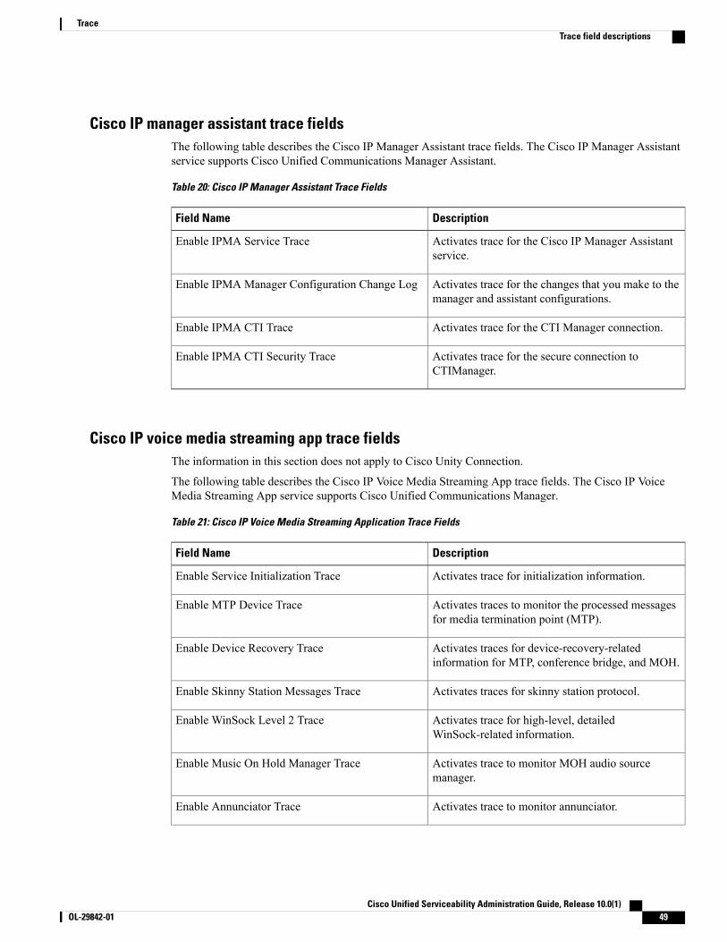
Cisco IP manager assistant trace fieldsThe following table describes the Cisco IP Manager Assistant trace fields. The Cisco IP Manager Assistantservice supports Cisco Unified Communications Manager Assistant.
Table 20: Cisco IP Manager Assistant Trace Fields
DescriptionField Name
Activates trace for the Cisco IP Manager Assistantservice.
Enable IPMA Service Trace
Activates trace for the changes that you make to themanager and assistant configurations.
Enable IPMA Manager Configuration Change Log
Activates trace for the CTI Manager connection.Enable IPMA CTI Trace
Activates trace for the secure connection toCTIManager.
Enable IPMA CTI Security Trace
Cisco IP voice media streaming app trace fieldsThe information in this section does not apply to Cisco Unity Connection.
The following table describes the Cisco IP Voice Media Streaming App trace fields. The Cisco IP VoiceMedia Streaming App service supports Cisco Unified Communications Manager.
Table 21: Cisco IP Voice Media Streaming Application Trace Fields
DescriptionField Name
Activates trace for initialization information.Enable Service Initialization Trace
Activates traces to monitor the processed messagesfor media termination point (MTP).
Enable MTP Device Trace
Activates traces for device-recovery-relatedinformation for MTP, conference bridge, and MOH.
Enable Device Recovery Trace
Activates traces for skinny station protocol.Enable Skinny Station Messages Trace
Activates trace for high-level, detailedWinSock-related information.
Enable WinSock Level 2 Trace
Activates trace to monitor MOH audio sourcemanager.
Enable Music On Hold Manager Trace
Activates trace to monitor annunciator.Enable Annunciator Trace
Cisco Unified Serviceability Administration Guide, Release 10.0(1) OL-29842-01 49
TraceTrace field descriptions

DescriptionField Name
Activates trace to monitor database setup and changesfor MTP, conference bridge, and MOH.
Enable DB Setup Manager Trace
Activates traces to monitor the processed messagesfor conference bridge.
Enable Conference Bridge Device Trace
Activates device driver traces.Enable Device Driver Trace
Activates trace for low-level, general,WinSock-related information.
Enable WinSock Level 1 Trace
Activates traces to monitor the processed messagesfor MOH.
Enable Music on Hold Device Trace
Activates trace to monitor the download of MOHaudio source files.
Enable TFTP Downloads Trace
Cisco TFTP trace fieldsThe following table describes the Cisco TFTP trace fields. The Cisco TFTP service supports Cisco UnifiedCommunications Manager.
Table 22: Cisco TFTP Trace Fields
DescriptionField Name
Activates trace for service system.Enable Service System Trace
Activates trace for build files.Enable Build File Trace
Activates trace for serve files.Enable Serve File Trace
Cisco Web Dialer web service trace fieldsThe following table describes the Cisco Web Dialer Web Service trace fields. The Cisco Web Dialer WebService supports Cisco Unified Communications Manager.
Table 23: Cisco Web Dialer Web Service Trace Fields
DescriptionField Name
Activates trace for Cisco Web Dialer servlet.Enable Web Dialer Servlet Trace
Activates trace for the Redirector servlet.Enable Redirector Servlet Trace
Cisco Unified Serviceability Administration Guide, Release 10.0(1)50 OL-29842-01
TraceTrace field descriptions

IM and Presence SIP proxy service trace filter settingsThe following table below describes the service trace filter settings for the IM and Presence SIP Proxy.
Table 24: IM and Presence SIP proxy service trace filter settings
DescriptionParameter
This parameter enables the proxy access log trace; the first line of each SIPmessage received by the proxy is logged.
Enable Access Log Trace
This parameter enables tracing for the Authentication module.Enable AuthenticationTrace
This parameter enables tracing for the Calendar module.Enable CALENDARTrace
This parameter enables tracing for the CTI Gateway.Enable CTI GatewayTrace
This parameter enables tracing for the Enum module.Enable Enum Trace
This parameter enables tracing for the Method/Event routing module.Enable Method/EventRouting Trace
This parameter enables tracing for the Number Expansion module.Enable NumberExpansion Trace
This parameter enables tracing of parser information related to the operation ofthe per-sipd child SIP parser.
Enable Parser Trace
This parameter enables tracing for information about processing of PAI, RPID,and Diversion headers in relation to privacy requests.
Enable Privacy Trace
This parameter enables tracing for the Registry module.Enable Registry Trace
This parameter enables tracing for the Routing module.Enable Routing Trace
This parameter enables tracing for the SIP UA application module.Enable SIPUA Trace
This parameter enables tracing for the Server.Enable Server Trace
This parameter enables tracing for information related to the operation of theper-sipd SIP state machine.
Enable SIP Message andState Machine Trace
This parameter enables tracing for information related to the TCP transport ofSIP messages by TCP services.
Enable SIP TCP Trace
This parameter enables tracing for information related to the TLS transport ofSIP messages by TCP services.
Enable SIP TLS Trace
Cisco Unified Serviceability Administration Guide, Release 10.0(1) OL-29842-01 51
TraceIM and Presence SIP proxy service trace filter settings
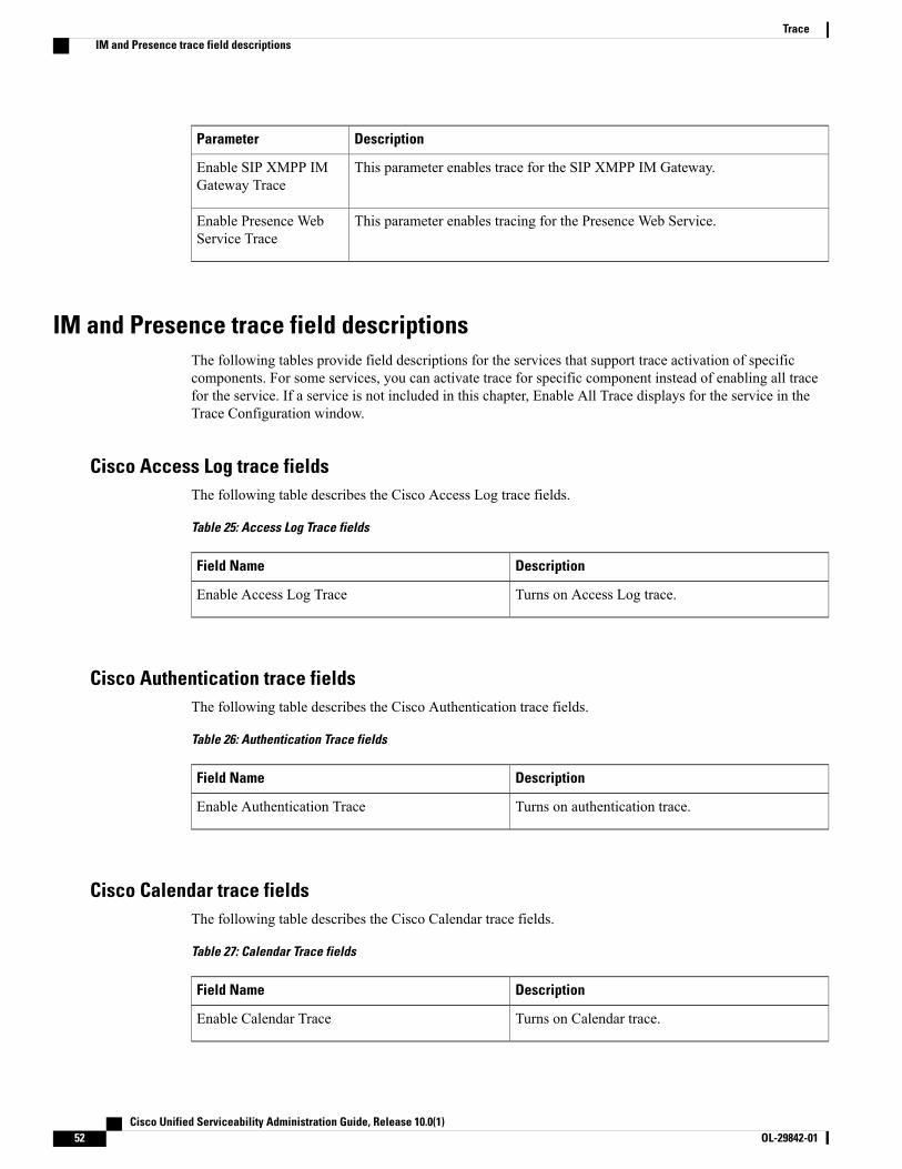
DescriptionParameter
This parameter enables trace for the SIP XMPP IM Gateway.Enable SIP XMPP IMGateway Trace
This parameter enables tracing for the Presence Web Service.Enable Presence WebService Trace
IM and Presence trace field descriptionsThe following tables provide field descriptions for the services that support trace activation of specificcomponents. For some services, you can activate trace for specific component instead of enabling all tracefor the service. If a service is not included in this chapter, Enable All Trace displays for the service in theTrace Configuration window.
Cisco Access Log trace fieldsThe following table describes the Cisco Access Log trace fields.
Table 25: Access Log Trace fields
DescriptionField Name
Turns on Access Log trace.Enable Access Log Trace
Cisco Authentication trace fieldsThe following table describes the Cisco Authentication trace fields.
Table 26: Authentication Trace fields
DescriptionField Name
Turns on authentication trace.Enable Authentication Trace
Cisco Calendar trace fieldsThe following table describes the Cisco Calendar trace fields.
Table 27: Calendar Trace fields
DescriptionField Name
Turns on Calendar trace.Enable Calendar Trace
Cisco Unified Serviceability Administration Guide, Release 10.0(1)52 OL-29842-01
TraceIM and Presence trace field descriptions

Cisco CTI Gateway trace fieldsThe following table describes the Cisco CTI Gateway trace fields.
Table 28: CTI Gateway Trace Fields
DescriptionField Name
Turns on CTI Gateway trace.Enable CTI Gateway Trace
Cisco Database Layer Monitor trace fieldsThe following table describes the Cisco Database Layer Monitor trace fields.
Table 29: Cisco Database Layer Monitor Trace Fields
DescriptionField Name
Turns on database library trace for C++ applications.Enable DB Library Trace
Turns on service trace.Enable Service Trace
Activates the database change notification traces forC++ applications.
Enable DB Change Notification Trace
Do not check. Cisco engineering uses it for debuggingpurposes.
Enable Unit Test Trace
Cisco Enum trace fieldsThe following table describes the Cisco Enum trace fields.
Table 30: Enum Trace fields
DescriptionField Name
Turns on Enum trace.Enable Enum Trace
Cisco Method/Event trace fieldsThe following table describes the Cisco Method/Event trace fields.
Cisco Unified Serviceability Administration Guide, Release 10.0(1) OL-29842-01 53
TraceIM and Presence trace field descriptions

Table 31: Method/Event Trace fields
DescriptionField Name
Turns on Method/Event trace.Enable Method/Event Trace
Cisco Number Expansion trace fieldsThe following table describes the Cisco Number Expansion trace fields.
Table 32: Number Expansion Trace fields
DescriptionField Name
Activates number expansion trace.Enable Number Expansion Trace
Cisco Parser trace fieldsThe following table describes the Cisco Parser trace fields.
Table 33: Parser Trace Fields
DescriptionField Name
Activates parser trace.Enable Parser Trace
Cisco Privacy trace fieldsThe following table describes the Cisco Privacy trace fields.
Table 34: PrivacyTrace fields
DescriptionField Name
Activates Privacy trace.Enable Privacy Trace
Cisco Proxy trace fieldsThe following table describes the Cisco proxy trace fields.
Cisco Unified Serviceability Administration Guide, Release 10.0(1)54 OL-29842-01
TraceIM and Presence trace field descriptions

Table 35: Proxy Trace Fields
DescriptionField Name
Turns on Proxy trace.Add Proxy
Cisco RIS Data Collector trace fieldsThe following table describes the Cisco RIS Data Collector trace fields.
Table 36: Cisco RIS Data Collector Trace Fields
DescriptionField Name
Activates trace for the RISDC thread of the RIS datacollector service (RIS).
Enable RISDC Trace
Activates trace for the system access library in theRIS data collector.
Enable System Access Trace
Activates trace for the link services library in the RISdata collector.
Enable Link Services Trace
Activates trace for the RISDC access library in theRIS data collector.
Enable RISDC Access Trace
Activates trace for the RISDB library in the RIS datacollector.
Enable RISDB Trace
Activates trace for the PI library in the RIS datacollector.
Enable PI Trace
Activates trace for the input/output XML messagesof the RIS data collector service.
Enable XML Trace
Activates trace for the troubleshooting perfmon datalogging in the RIS data collector. Used to trace thename of the log file, the total number of counters thatare logged, the names of the application and systemcounters and instances, calculation of process andthread CPU percentage, and occurrences of log filerollover and deletion.
Enable Perfmon Logger Trace
Cisco Registry trace fieldsThe following table describes the Cisco Registry trace fields.
Cisco Unified Serviceability Administration Guide, Release 10.0(1) OL-29842-01 55
TraceIM and Presence trace field descriptions
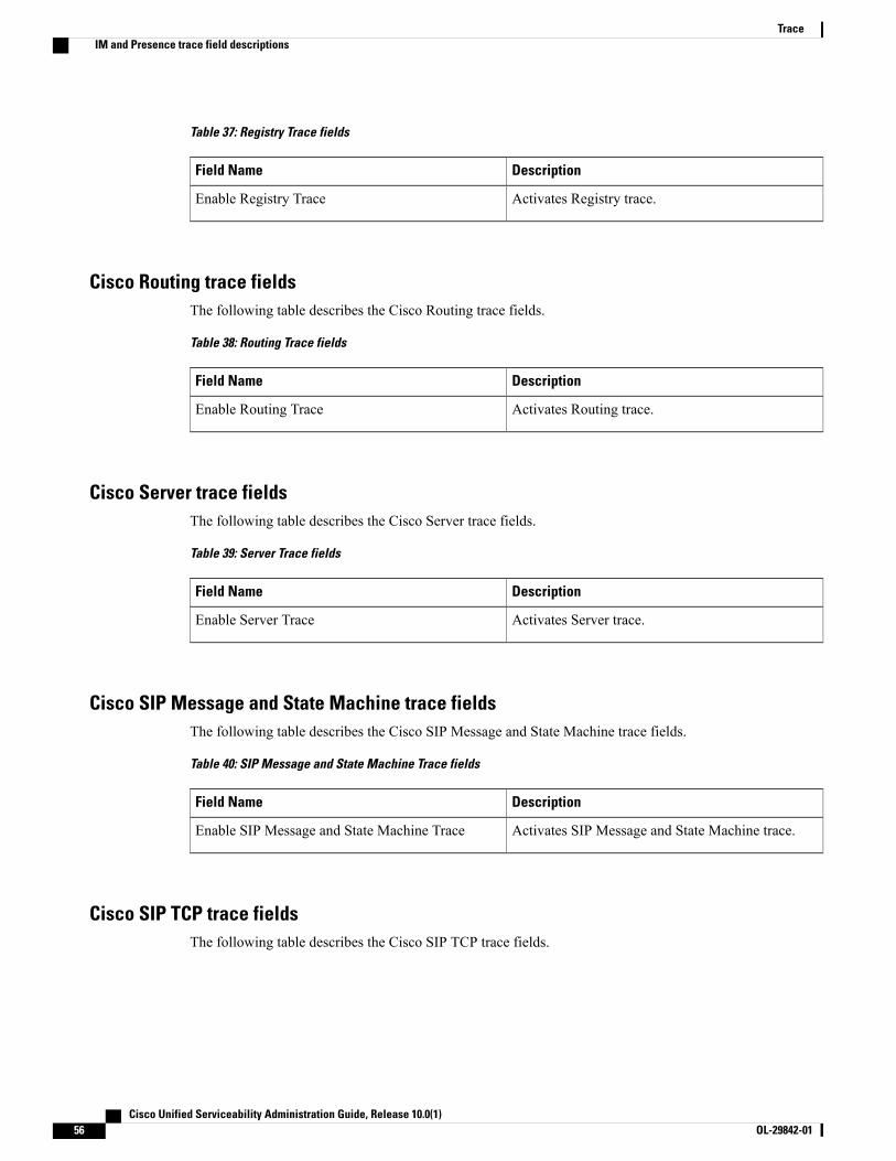
Table 37: Registry Trace fields
DescriptionField Name
Activates Registry trace.Enable Registry Trace
Cisco Routing trace fieldsThe following table describes the Cisco Routing trace fields.
Table 38: Routing Trace fields
DescriptionField Name
Activates Routing trace.Enable Routing Trace
Cisco Server trace fieldsThe following table describes the Cisco Server trace fields.
Table 39: Server Trace fields
DescriptionField Name
Activates Server trace.Enable Server Trace
Cisco SIP Message and State Machine trace fieldsThe following table describes the Cisco SIP Message and State Machine trace fields.
Table 40: SIP Message and State Machine Trace fields
DescriptionField Name
Activates SIP Message and State Machine trace.Enable SIP Message and State Machine Trace
Cisco SIP TCP trace fieldsThe following table describes the Cisco SIP TCP trace fields.
Cisco Unified Serviceability Administration Guide, Release 10.0(1)56 OL-29842-01
TraceIM and Presence trace field descriptions
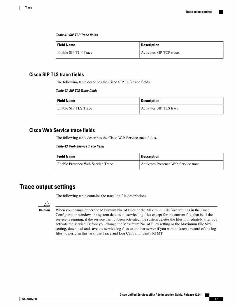
Table 41: SIP TCP Trace fields
DescriptionField Name
Activates SIP TCP trace.Enable SIP TCP Trace
Cisco SIP TLS trace fieldsThe following table describes the Cisco SIP TLS trace fields.
Table 42: SIP TLS Trace fields
DescriptionField Name
Activates SIP TLS trace.Enable SIP TLS Trace
Cisco Web Service trace fieldsThe following table describes the Cisco Web Service trace fields.
Table 43: Web Service Trace fields
DescriptionField Name
Activates Presence Web Service trace.Enable Presence Web Service Trace
Trace output settingsThe following table contains the trace log file descriptions.
When you change either the Maximum No. of Files or the Maximum File Size settings in the TraceConfiguration window, the system deletes all service log files except for the current file, that is, if theservice is running; if the service has not been activated, the system deletes the files immediately after youactivate the service. Before you change the Maximum No. of Files setting or the Maximum File Sizesetting, download and save the service log files to another server if you want to keep a record of the logfiles; to perform this task, use Trace and Log Central in Unity RTMT.
Caution
Cisco Unified Serviceability Administration Guide, Release 10.0(1) OL-29842-01 57
TraceTrace output settings
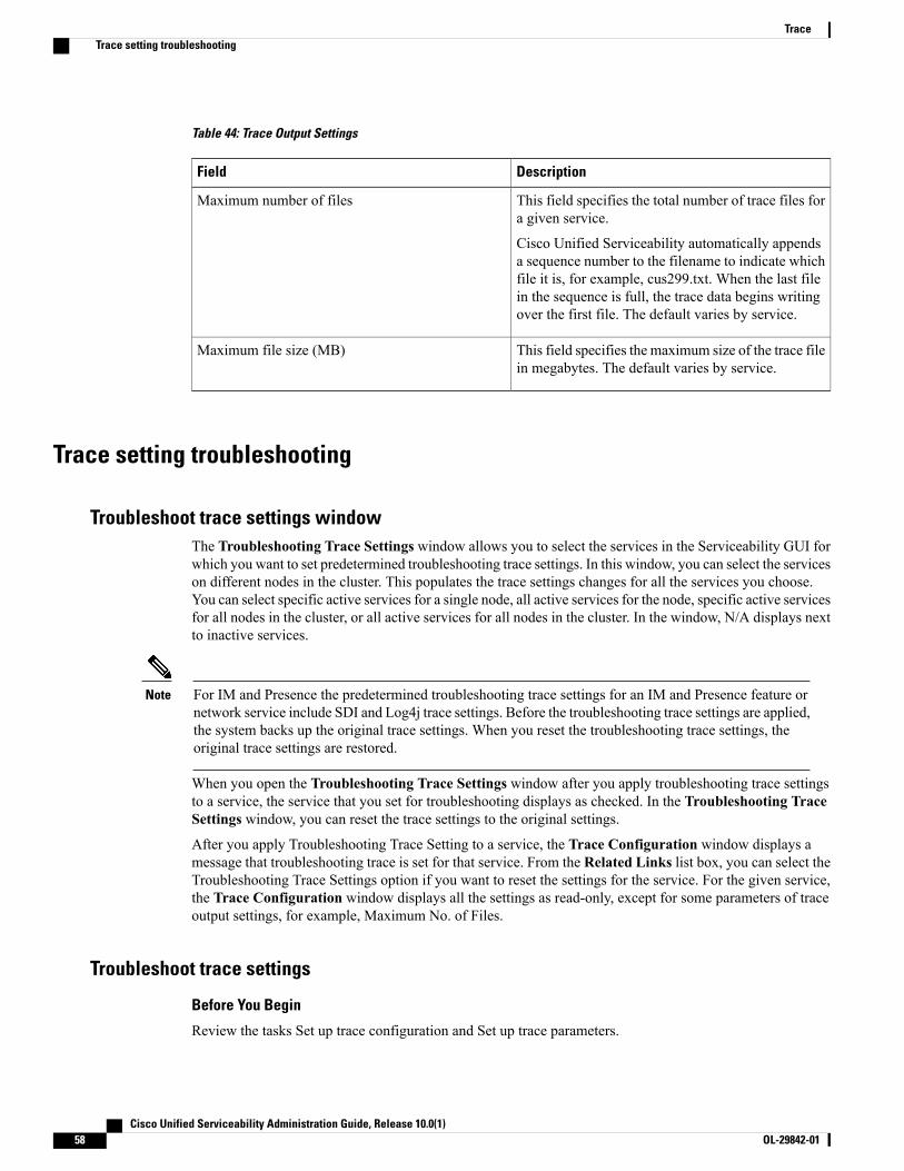
Table 44: Trace Output Settings
DescriptionField
This field specifies the total number of trace files fora given service.
Cisco Unified Serviceability automatically appendsa sequence number to the filename to indicate whichfile it is, for example, cus299.txt. When the last filein the sequence is full, the trace data begins writingover the first file. The default varies by service.
Maximum number of files
This field specifies the maximum size of the trace filein megabytes. The default varies by service.
Maximum file size (MB)
Trace setting troubleshooting
Troubleshoot trace settings windowThe Troubleshooting Trace Settings window allows you to select the services in the Serviceability GUI forwhich you want to set predetermined troubleshooting trace settings. In this window, you can select the serviceson different nodes in the cluster. This populates the trace settings changes for all the services you choose.You can select specific active services for a single node, all active services for the node, specific active servicesfor all nodes in the cluster, or all active services for all nodes in the cluster. In the window, N/A displays nextto inactive services.
For IM and Presence the predetermined troubleshooting trace settings for an IM and Presence feature ornetwork service include SDI and Log4j trace settings. Before the troubleshooting trace settings are applied,the system backs up the original trace settings. When you reset the troubleshooting trace settings, theoriginal trace settings are restored.
Note
When you open the Troubleshooting Trace Settings window after you apply troubleshooting trace settingsto a service, the service that you set for troubleshooting displays as checked. In the Troubleshooting TraceSettings window, you can reset the trace settings to the original settings.
After you apply Troubleshooting Trace Setting to a service, the Trace Configuration window displays amessage that troubleshooting trace is set for that service. From the Related Links list box, you can select theTroubleshooting Trace Settings option if you want to reset the settings for the service. For the given service,the Trace Configuration window displays all the settings as read-only, except for some parameters of traceoutput settings, for example, Maximum No. of Files.
Troubleshoot trace settings
Before You Begin
Review the tasks Set up trace configuration and Set up trace parameters.
Cisco Unified Serviceability Administration Guide, Release 10.0(1)58 OL-29842-01
TraceTrace setting troubleshooting
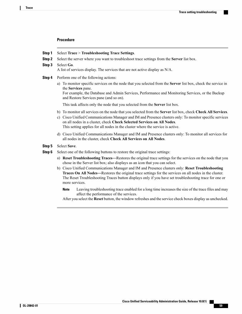
Procedure
Step 1 Select Trace > Troubleshooting Trace Settings.Step 2 Select the server where you want to troubleshoot trace settings from the Server list box.Step 3 Select Go.
A list of services display. The services that are not active display as N/A.
Step 4 Perform one of the following actions:a) To monitor specific services on the node that you selected from the Server list box, check the service in
the Services pane.For example, the Database and Admin Services, Performance and Monitoring Services, or the Backupand Restore Services pane (and so on).
This task affects only the node that you selected from the Server list box.
b) To monitor all services on the node that you selected from the Server list box, check Check All Services.c) Cisco Unified Communications Manager and IM and Presence clusters only: To monitor specific services
on all nodes in a cluster, check Check Selected Services on All Nodes.This setting applies for all nodes in the cluster where the service is active.
d) Cisco Unified Communications Manager and IM and Presence clusters only: To monitor all services forall nodes in the cluster, check Check All Services on All Nodes.
Step 5 Select Save.Step 6 Select one of the following buttons to restore the original trace settings:
a) Reset Troubleshooting Traces—Restores the original trace settings for the services on the node that youchose in the Server list box; also displays as an icon that you can select.
b) Cisco Unified Communications Manager and IM and Presence clusters only: Reset TroubleshootingTraces On All Nodes—Restores the original trace settings for the services on all nodes in the cluster.The Reset Troubleshooting Traces button displays only if you have set troubleshooting trace for one ormore services.
Leaving troubleshooting trace enabled for a long time increases the size of the trace files and mayaffect the performance of the services.
Note
After you select theReset button, the window refreshes and the service check boxes display as unchecked.
Cisco Unified Serviceability Administration Guide, Release 10.0(1) OL-29842-01 59
TraceTrace setting troubleshooting

Cisco Unified Serviceability Administration Guide, Release 10.0(1)60 OL-29842-01
TraceTrace setting troubleshooting

C H A P T E R 5Services
• Feature services, page 61
• Network services, page 72
• Services setup, page 81
Feature servicesUse the Serviceability GUI to activate, start, and stop Cisco Unified Communications Manager and IM andPresence services. Activation turns on and starts a service. You must manually activate the feature service forall features that youwant to use. For service-activation recommendations, see topics related to service activation.
If you try to access a Cisco Unified Communications Manager server from an IM and Presence node orvice versa, you may encounter the following error: "Connection to the Server cannot be established (unableto access Remote Node)" . If this error message appears, see theCisco Unified Communications OperatingSystem Administration Guide, Release 10.0(1).
Note
After you activate a service in the Service Activation window, you do not need to start it in the ControlCenter - Feature Serviceswindow. If the service does not start for any reason, you must start it in theControlCenter - Feature Services window.
After the system is installed, it does not automatically activate feature services, You need to activate the featureservice to use your configuration features, for example, the Serviceability Reports Archive feature.
Cisco Unified CommunicationsManager and CiscoUnified IM and Presence Service only: If you are upgradingCisco Unified Communications Manager, those services that you activated on the system before the upgradeautomatically start after the upgrade.
After you activate feature services, you can modify service parameter settings using the administrative GUIfor your product:
• Cisco Unified Communications Manager Administration
• Cisco Unity Connection Administration
Cisco Unified Serviceability Administration Guide, Release 10.0(1) OL-29842-01 61
Feature services categories
In Cisco Unified Serviceability, the Service Activation window and the Control Center - Feature Serviceswindow categorize feature services into the following groups:
• Database and administration services
• Performance and monitoring services
• CM services
• CTI services
• CDR services
• Security services
• Directory services
• Voice quality reporter services
In Cisco Unified IM and Presence Serviceability, the Service Activation window and the Control Center -Feature Services window categorize feature services into the following groups:
• Database and administration services
• Performance and monitoring services
• IM and Presence Service services
Database and administration services
Locations Bandwidth ManagerThis service is not supported by IM and Presence Service.
The Locations Bandwidth Manager service assembles a network model from configured Location and Linkdata in one or more clusters, determines the Effective Paths between pairs of Locations, determines whetherto admit calls between a pair of Locations based on the availability of bandwidth for each type of call, anddeducts (reserves) bandwidth for the duration of each call that is admitted.
Cisco AXL Web ServiceThe Cisco AXL Web Service allows you to modify database entries and execute stored procedures fromclient-based applications that use AXL.
In an IM and Presence Service system, this service supports both Cisco Unified Communications Managerand Cisco Unity Connection.
Cisco UXL Web ServiceThis service is not supported by IM and Presence Service.
The TabSync client in Cisco IP Phone Address Book Synchronizer uses the Cisco UXL Web Service forqueries to the Cisco Unified Communications Manager database, which ensures that Cisco IP Phone Address
Cisco Unified Serviceability Administration Guide, Release 10.0(1)62 OL-29842-01
ServicesDatabase and administration services
Book Synchronizer users have access only to end-user data that pertains to them. The Cisco UXLWeb Serviceperforms the following functions:
• Conducts authentication checks by verifying the end-user username and password when an end userlogs in to Cisco IP Phone Address Book Synchronizer.
• Conducts a user authorization check by only allowing the user that is currently logged in to Cisco IPPhone Address Book Synchronizer to perform functions such as listing, retrieving, updating, removing,and adding contacts.
Cisco Bulk Provisioning ServiceThis service does not support Cisco Unity Connection.
If your configuration supports clusters (Cisco Unified Communications Manager only), you can activate theCisco Bulk Provisioning Service only on the first server. If you use the Cisco Unified CommunicationsManager Bulk Administration Tool to administer phones and users, you must activate this service.
Platform Administrative Web ServiceThe Platform Administrative Web Service provides a web-based interface to facilitate your system upgradesand Cisco Options Package (COP) file installs. This web-based interface also enables large-scale deploymentsof to be initiated and monitored from a single management client. If you need to manage system upgrades,this service must be turned on for all IM and Presence Service and Cisco Unified Communications Managernodes.
Cisco TAPS ServiceThis service does not support Cisco Unity Connection or IM and Presence Service.
The Cisco Tools for Auto-Registered Phones Support (TAPS) Service supports the Cisco UnifiedCommunicationsManager Auto-Register Phone Tool, which allows a user to upload a customized configurationon an auto registered phone after a user responds to Interactive Voice Response (IVR) prompts.
If your configuration supports clusters (Cisco Unified Communications Manager only), you activate thisservice on the first server. When you want to create dummyMAC addresses for the tool, ensure that the CiscoBulk Provisioning Service is activated on the same server.
The CiscoUnified CommunicationsManager Auto-Register Phone Tool relies on Cisco Customer ResponseSolutions (CRS). Before the tool can work as designed, verify that the CRS server is configured andrunning, as described in the CRS documentation.
Tip
Platform Administrative Web ServiceThe PlatformAdministrativeWeb Service is a Simple Object Access Protocol (SOAP) API that can be activatedon Cisco Unified Communications Manager, IM and Presence Service, and Cisco Unity Connection systemsto allow the PAWS-M server to upgrade the system.
Cisco Unified Serviceability Administration Guide, Release 10.0(1) OL-29842-01 63
ServicesDatabase and administration services

Do not activate the Platform Administrative Web Service on the PAWS-M server.Important
Performance and monitoring services
Cisco Serviceability ReporterThe Cisco Serviceability Reporter service generates daily reports. For details, see topics that are related tothe serviceability reports archive.
If your configuration supports clusters (Cisco Unified CommunicationsManager only), this service is installedon all the Cisco Unified Communications Manager servers in the cluster. Reporter generates reports once aday based on logged information. You can access the reports that Reporter generates in Cisco UnifiedServiceability from the Tools menu. Each summary report comprises different charts that display the statisticsfor that particular report. After you activate the service, report generation may take up to 24 hours.
Related Topics
Serviceability Reports Archive, on page 93
Cisco CallManager SNMP ServiceThis service does not support IM and Presence Service and Cisco Unity Connection.
This service, which implements the CISCO-CCM-MIB, provides SNMP access to provisioning and statisticsinformation that is available for Cisco Unified Communications Manager.
If your configuration supports clusters (Cisco Unified Communications Manager only), activate this serviceon all servers in the cluster.
CM servicesThis section describes the CM Services and does not apply to IM and Presence Service and Cisco UnityConnection.
Cisco CallManagerThe Cisco CallManager Service provides software-only call processing as well as signaling and call controlfunctionality for Cisco Unified Communications Manager.
Cisco Unified Serviceability Administration Guide, Release 10.0(1)64 OL-29842-01
ServicesPerformance and monitoring services
Cisco Unified Communications Manager clusters only: Before you activate this service, verify that theCiscoUnified CommunicationsManager server displays in the Find and List CiscoUnified CommunicationsManagers window in Cisco Unified Communications Manager Administration. If the server does notdisplay, add the Cisco Unified Communications Manager server before you activate this service. Forinformation on how to find and add the server, see the Cisco Unified Communications ManagerAdministration Guide.
Cisco Unified Communications Manager clusters only: If you deactivate the Cisco CallManager orCTIManager services in Service Activation, the Cisco Unified Communications Manager server whereyou deactivated the service no longer exists in the database, which means that you cannot choose thatCisco Unified Communications Manager server for configuration operations in Cisco UnifiedCommunicationsManager Administration because it does not display in the graphical user interface (GUI).If you then reactivate the services on the same Cisco Unified CommunicationsManager server, the databasecreates an entry for Cisco Unified Communications Manager again and adds a “CM_” prefix to the servername or IP address; for example, if you reactivate the Cisco CallManager or CTIManager service on aserver with an IP address of 172.19.140.180, then CM_172.19.140.180 displays in Cisco UnifiedCommunications Manager Administration. You can now choose the server, with the new “CM_” prefix,in Cisco Unified Communications Manager Administration.
Tip
The following services rely on Cisco CallManager service activation:
• CM services
• CDR services
Cisco TFTPCisco Trivial File Transfer Protocol (TFTP) builds and serves files that are consistent with the trivial filetransfer protocol, a simplified version of FTP. Cisco TFTP serves embedded component executable, ringerfiles, and device configuration files.
Cisco Unified Communications Manager only: A configuration file includes a list of Cisco UnifiedCommunications Managers to which devices (telephones and gateways) make connections. When a deviceboots, the component queries a Dynamic Host Configuration Protocol (DHCP) server for its networkconfiguration information. The DHCP server responds with an IP address for the device, a subnet mask, adefault gateway, a Domain Name System (DNS) server address, and a TFTP server name or address. Thedevice requests a configuration file from the TFTP server. The configuration file contains a list of CiscoUnified Communications Managers and the TCP port through which the device connects to those CiscoUnified Communications Managers. The configuration file contains a list of Cisco Unified CommunicationsManagers and the TCP port through which the device connects to those Cisco Unified CommunicationsManagers.
Cisco Unified Mobile Voice Access ServiceThe Cisco Unified Voice Access Service starts the mobile voice access capability within Cisco UnifiedMobility; mobile voice access, which is an integrated voice response (IVR) system, allows Cisco UnifiedMobility users to perform the following tasks:
• Make calls from the cellular phone as if the call originated from the desk phone.
• Turn Cisco Unified Mobility on.
Cisco Unified Serviceability Administration Guide, Release 10.0(1) OL-29842-01 65
ServicesCM services
• Turn Cisco Unified Mobility off.
Cisco IP Voice Media Streaming AppThe Cisco IP Voice Media Streaming Application service provides voice media streaming functionality forCisco Unified Communications Manager for use with Media Termination Point (MTP), conferencing, musicon hold (MOH), and annunciator. The Cisco IP Voice Media Streaming Application relays messages fromCisco Unified Communications Manager to the IP voice media streaming driver, which handles Real-TimeProtocol (RTP) streaming.
The Cisco IP Voice Media Streaming Application service does not generate the Call Management Record(CMR) files for call legs that involve any IP VoiceMedia Streaming Application components like conference,MOH, annunciator, or MTP.
Cisco CTIManagerThe Cisco CTI Manager contains the CTI components that interact with applications. This service allowsapplications to monitor or control phones and virtual devices to perform call control functionality.
Cisco Unified Communications Manager clusters only: With CTI Manager, applications can access resourcesand functionality of all Cisco Unified Communications Managers in the cluster and have improved failovercapability. Although one or more CTI Managers can be active in a cluster, only one CTI Manager can existon an individual server. An application (JTAPI/TAPI) can have simultaneous connections to multiple CTIManagers; however, an application can use only one connection at a time to open a device with mediatermination.
Cisco Extension MobilityThis service, which supports the Cisco Extension Mobility feature, performs the login and automatic logoutfunctionality for the feature.
Cisco Dialed Number AnalyzerThe Cisco Dialed Number Analyzer service supports Cisco Unified CommunicationsManager Dialed NumberAnalyzer. When activated, this application consumes a lot of resources, so activate this service only duringoff-peak hours when minimal call-processing interruptions may occur.
Cisco Unified CommunicationsManager clusters only: Cisco does not recommend that you activate the serviceon all the servers in a cluster. Cisco recommends that you activate this service only on one of the servers ofa cluster where call-processing activity is the least.
Cisco Dialed Number Analyzer ServerThe Cisco Dialed Number Analyzer Server service along with The Cisco Dialed Number Analyzer servicesupports Cisco Unified CommunicationsManager Dialed Number Analyzer. This service needs to be activatedonly on the node that is dedicated specifically for the Cisco Dialed Number Analyzer service.
Cisco Unified CommunicationsManager clusters only: Cisco does not recommend that you activate the serviceon all the servers in a cluster. Cisco recommends that you activate this service only on one of the servers ofa cluster where call-processing activity is the least.
Cisco Unified Serviceability Administration Guide, Release 10.0(1)66 OL-29842-01
ServicesCM services

Cisco DHCP Monitor ServiceCisco DHCP Monitor Service monitors IP address changes for IP phones in the database tables. When achange is detected, it modifies the /etc./dhcpd.conf file and restarts the DHCPD daemon.
Cisco Intercluster Lookup ServiceThe Intercluster Lookup Service (ILS) runs on a cluster-wide basis. ILS allows you to create networks ofremote Cisco Unified Communications Manager clusters. The ILS cluster discovery feature allows CiscoUnified Communications Manager to connect to remote clusters without the need for an administrator havingto manually configure connections between each cluster. The ILS Global Dial Plan Replication feature enablesclusters in the ILS network with the ability to exchange global dial plan data with the other clusters in an ILSnetwork.
ILS can be activated from the ILSConfigurationwindow that can be accessed in CiscoUnified CommunicationsManager Administration by selecting Advanced Features > ILS Configuration.
Cisco UserSync ServiceCisco UserSync service synchronizes the data from Cisco Unified Communications Manager end-user tableto the LDAP database.
Cisco UserLookup Web ServiceCisco UserLookup Web service routes the commercial calls (calls through external gateways) to an alternateinternal number of the called party in order to avoid the commercial cost of calling an external number.
If a caller within a Cisco Unified Communications Manager network makes a call on an external number,Cisco Unified Communications Manager checks if an internal number exists for the called party in the LDAPdatabase. If an internal number exists, the call is routed to that internal number. If the internal number is notfound in the LDAP database, the call is routed to the original (external) number.
IM and Presence servicesIM and Presence services apply only to IM and Presence Service.
Cisco SIP ProxyThe Cisco SIP Proxy service is responsible for providing the SIP registrar and proxy functionality. Thisincludes request routing, requestor identification, and transport interconnection.
Cisco Presence EngineThe Cisco Presence Engine collects, aggregates, and distributes user capabilities and attributes using thestandards-based SIP and SIMPLE interface. It collects information about the availability status andcommunications capabilities of a user.
Cisco Unified Serviceability Administration Guide, Release 10.0(1) OL-29842-01 67
ServicesIM and Presence services

Cisco XCP Text Conference ManagerThe Cisco XCP Text Conference Manager supports the Chat feature. The Chat feature allows users tocommunicate with each other in online chat rooms. It supports chat functionality using ad hoc (temporary)and permanent chat rooms, which remain on a Cisco-supported external database until they are deleted.
Cisco XCP Web Connection ManagerThe Cisco XCPWeb ConnectionManager service enables browser-based clients to connect to IM and PresenceService.
Cisco XCP Connection ManagerThe Cisco XCP Text Conference Manager supports the Chat feature. The Chat feature allows users tocommunicate with each other in online chat rooms. It supports chat functionality using ad hoc (temporary)and permanent chat rooms, which remain on a Cisco-supported external database until they are deleted.
Cisco XCP SIP Federation Connection ManagerThe Cisco XCP SIP Federation Connection Manager supports interdomain federation with Microsoft OCSover the SIP protocol. You must also turn on this service when your deployment contains an interclusterconnection between an IM and Presence Service Release 9.0 cluster, and a Cisco Unified Presence Release8.6 cluster.
Cisco XCP XMPP Federation Connection ManagerThe Cisco XCP XMPP Federation Connection Manager supports interdomain federation with third partyenterprises such as IBM Lotus Sametime, Cisco Webex Meeting Center, and GoogleTalk over the XMPPprotocol, as well as supports interdomain federation with another IM and Presence Service enterprise overthe XMPP protocol.
Cisco XCP Message ArchiverThe Cisco XCP Message Archiver service supports the IM Compliance feature. The IM Compliance featurelogs all messages sent to and from the IM and Presence Service server, including point-to-point messages,and messages from ad hoc (temporary) and permanent chat rooms for the Chat feature. Messages are loggedto an external Cisco-supported database.
Cisco XCP Directory ServiceThe Cisco XCP Directory Service supports the integration of XMPP clients with the LDAP directory to allowusers to search and add contacts from the LDAP directory.
Cisco Unified Serviceability Administration Guide, Release 10.0(1)68 OL-29842-01
ServicesIM and Presence services

Cisco XCP Authentication ServiceThe Cisco XCP Authentication Service handles all authentication requests from XMPP clients that areconnecting to IM and Presence Service.
CTI servicesThis section describes the CTI Services and does not apply to Cisco Unity Connection or IM and PresenceService.
Cisco IP Manager AssistantThis service supports Cisco Unified Communications Manager Assistant. After service activation, CiscoUnified Communications Manager Assistant enables managers and their assistants to work together moreeffectively. Cisco Unified Communications Manager Assistant supports two modes of operation: proxy linesupport and shared line support.
The feature comprises a call-routing service, enhancements to phone capabilities for the manager, and desktopinterfaces that are primarily used by the assistant.
The service intercepts calls that are made to managers and routes them to selected assistants, to managers, orto other targets on the basis of preconfigured call filters. The manager can change the call routing dynamically;for example, by pressing a softkey on the phone, the manager can instruct the service to route all calls to theassistant and can receive status on these calls.
CiscoUnified CommunicationsManager users comprisemanagers and assistants. The routing service interceptsmanager calls and routes them appropriately. An assistant user handles calls on behalf of a manager.
Cisco WebDialer Web Service
Cisco WebDialer Web Service for Cisco Unified Communications Manager Systems
CiscoWeb Dialer provides click-to-dial functionality. It allows users inside a Cisco Unified CommunicationsManager cluster to initiate a call to other users inside or outside the cluster by using a web page or a desktopapplication. CiscoWeb Dialer provides a web page that enables users to call each other within a cluster. CiscoWeb Dialer comprises two components: Web Dialer servlet and Redirector servlet.
The Redirector servlet provides the ability for third-party applications to use CiscoWeb Dialer. The Redirectorservlet finds the appropriate Cisco Unified Communications Manager cluster for the Cisco Web Dialer userand redirects the request to the Cisco Web Dialer in that cluster. The Redirector functionality applies only forHTTP/HTML-based Web Dialer client applications because it is not available for Simple Object AccessProtocol (SOAP)-based Web Dialer applications.
Self-Provisioning IVRWith the introduction of Self-Provisioning IVR Service, the autoregistered IP phones on the Cisco UnifiedCommunications Manager are assigned to users quickly with less effort. When you dial the CTI RP DN, thatis configured on the Self-Provisioning page, from an extension of a user that uses the IVR service, the phoneconnects to the Self-Provisioning IVR application and prompts you to provide the Self-Service credentials.
Cisco Unified Serviceability Administration Guide, Release 10.0(1) OL-29842-01 69
ServicesCTI services

Based on the validation of the Self-Service credentials that you provide, the IVR service assigns theautoregistered IP phones to the users.
You can configure self-provisioning even if the service is deactivated, but the administrator cannot assign IPphones to users using the IVR service. By default, this service is deactivated.
To enable the Self-Provisioning IVR service, you must also enable the Cisco CTI Manager service.
For more information about how to configure self-provisioning, see the Cisco Unified CommunicationsManager Administration Guide.
CDR servicesThis section describes the CDR Services and does not apply to IM and Presence Service and Cisco UnityConnection.
CAR Web ServiceThe Cisco CARWeb Service loads the user interface for CAR, a web-based reporting application that generateseither CSV or PDF reports by using CDR data.
Cisco SOAP - CDRonDemand ServiceThe Cisco SOAP - CDRonDemand Service, a SOAP/HTTPS-based service, runs on the CDR Repositoryserver. It receives SOAP requests for CDR filename lists that are based on a user-specified time interval (upto a maximum of 1 hour) and returns a list of filenames that fit the time duration that is specified in the request.This service also receives requests for delivery of a specific CDR/CMR file with the filename and the transfermethod (SFTP/FTP, server name, login info, directory) that is specified in the request.
If you are using a third-party billing application that accesses CDR data through an HTTPS/SOAP interface,activate this service.
Security servicesThis section describes the Security Services and does not apply to IM and Presence Service and Cisco UnityConnection.
Cisco CTL ProviderCisco Unified CommunicationsManager only: The Cisco Certificate Trust List (CTL) Provider service, whichruns with local system account privileges, works with the Cisco CTL Provider Utility, a client-side plug-in,to change the security mode for the cluster from nonsecure to mixed mode. When you install the plug-in, theCisco CTL Provider service retrieves a list of all Cisco Unified Communications Manager and Cisco TFTPservers in the cluster for the CTL file, which contains a list of security tokens and servers in the cluster. Youmust install and configure the Cisco CTL Client and activate this service for the clusterwide security modeto change from nonsecure to secure.
After you activate the service, the Cisco CTL Provider service reverts to the default CTL port, which is 2444.If you want to change the port, see the Cisco Unified Communications Manager Security Guide for moreinformation.
Cisco Unified Serviceability Administration Guide, Release 10.0(1)70 OL-29842-01
ServicesCDR services

Cisco Certificate Authority Proxy Function (CAPF)Working in conjunction with the Cisco Certificate Authority Proxy Function (CAPF) application, the CAPFservice can perform the following tasks, depending on your configuration:
• Issue locally significant certificates to supported Cisco Unified IP Phone models.
• Upgrade existing certificates on the phones.
• Retrieve phone certificates for troubleshooting.
• Delete locally significant certificates on the phone.
Cisco Unified Communications Manager only: When you view real-time information in the Real-TimeMonitoring Tool (RTMT), the CAPF service displays only for the first server.
Note
Directory servicesThis section describes the Directory Services and does not apply to IM and Presence Service and Cisco UnityConnection.
Cisco DirSyncCisco Unified Communications Manager: The Cisco DirSync service ensures that the Cisco UnifiedCommunications Manager database stores all user information. If you use an integrated corporate directory,for example, Microsoft Active Directory or Netscape/iPlanet Directory, with Cisco Unified CommunicationsManager, the Cisco DirSync service migrates the user data to the Cisco Unified Communications Managerdatabase. The Cisco DirSync service does not synchronize the passwords from the corporate directory.
Users with duplicate email IDs are not synchronized and the administrator receives no notification aboutthe list of users which are not synced. These IDS are shown in the DirSync error logs fromUnified RTMT.
Note
Cisco Unity Connection: When Cisco Unity Connection is integrated with an LDAP directory, the CiscoDirSync service synchronizes a small subset of user data (first name, last name, alias, phone number, and soon) in the Cisco Unified Communications Manager database on the Cisco Unity Connection server with thecorresponding data in the LDAP directory. Another service (CuCmDbEventListener) synchronizes data inthe Cisco Unity Connection user database with data in the Cisco Unified Communications Manager database.When a Cisco Unity Connection cluster is configured, the Cisco DirSync service runs only on the publisherserver.
Voice quality reporter servicesThis section describes the Voice Quality Reporter Services and does not apply to IM and Presence Serviceand Cisco Unity Connection.
Cisco Unified Serviceability Administration Guide, Release 10.0(1) OL-29842-01 71
ServicesDirectory services
Cisco Extended FunctionsThe Cisco Extended Functions service provides support for Cisco Unified Communications Managervoice-quality features, including Quality Report Tool (QRT). For more information about individual features,see the Cisco Unified Communications Manager System Guide and the Cisco Unified IPPhone Administration Guide for Cisco Unified Communications Manager.
Network servicesInstalled automatically, network services include services that the system requires to function, for example,database and platform services. Because these services are required for basic functionality, you cannot activatethem in the Service Activation window. If necessary, for example, for troubleshooting purposes, you mayneed to stop and start (or restart) a network service in the Control Center - Network Services window.
After the installation of your application, network services start automatically, as noted in the Control Center- Network Services window. The serviceability GUI categorizes services into logical groups.
Performance and monitoring services
Cisco CallManager Serviceability RTMT
The Cisco CallManager Serviceability RTMT servlet supports the IM and Presence Real-Time MonitoringTool (RTMT), which allows you to collect and view traces, view performance monitoring objects, work withalerts, and monitor system performance and performance counters, and so on.
Cisco RTMT Reporter Servlet
The Cisco RTMT Reporter servlet allows you to publish reports for RTMT.
Cisco Log Partition Monitoring Tool
The Cisco Log PartitionMonitoring Tool service supports the Log PartitionMonitoring feature, whichmonitorsthe disk usage of the log partition on a node (or all nodes in the cluster) by using configured thresholds anda polling interval.
Cisco Tomcat Stats Servlet
The Cisco Tomcat Stats Servlet allows you to monitor the Tomcat perfmon counters by using RTMT or theCLI. Do not stop this service unless you suspect that this service is using too many resources, such as CPUtime.
Cisco RIS Data Collector
The Real-Time Information Server (RIS) maintains real-time information such as device registration status,performance counter statistics, critical alarms generated, and so on. The Cisco RIS Data Collector serviceprovides an interface for applications, such as the IM and Presence Real-Time Monitoring Tool (RTMT),SOAP applications, and so on, to retrieve the information that is stored in all RIS nodes in the cluster.
Cisco Unified Serviceability Administration Guide, Release 10.0(1)72 OL-29842-01
ServicesNetwork services

Cisco AMC Service
Used for the Real-Time Monitoring Tool (RTMT), this service, Alert Manager and Collector service, allowsRTMT to retrieve real-time information that exists on the server (or on all servers in the cluster).
Cisco Audit Event Service
The Cisco Audit Event Service monitors and logs any administrative configuration change to the Cisco UnifiedCommunications Manager or IM and Presence system by a user or as a result of the user action. The CiscoAudit Event Service also monitors and logs end user events such as login, logout, and IM chat room entryand exit.
Backup and restore services
Cisco DRF Master
This does not apply to IM and Presence Service.
The CiscoDRFMaster Agent service supports the DRFMaster Agent, which works with the Disaster RecoverySystem GUI or CLI to schedule backups, perform restorations, view dependencies, check status of jobs, andcancel jobs, if necessary. The Cisco DRF Master Agent also provides the storage medium for the backup andrestoration process.
Cisco DRF Local
The Cisco DRF Local service supports the Cisco DRF Local Agent, which acts as the workhorse for the DRFMaster Agent. Components register with the Cisco DRF Local Agent to use the disaster recovery framework.The Cisco DRF Local Agent executes commands that it receives from the Cisco DRF Master Agent. CiscoDRF Local Agent sends the status, logs, and command results to the Cisco DRF Master Agent.
System services
Cisco CallManager Serviceability
The Cisco CallManager Serviceability service supports Cisco Unified Serviceability and the IM and PresenceService serviceability GUIs, which are web application/interfaces that you use to troubleshoot issues andmanage services. This service, which is installed automatically, allows you access to the serviceability GUIs.If you stop this service on the server, you cannot access the serviceability GUI when you browse into thatserver.
Cisco CDP
Cisco Discovery Protocol (CDP) advertises the voice application to other network management applications,so the network management application, for example, SNMP or Cisco Unified Operations Manager, canperform network management tasks for the voice application.
Cisco Trace Collection Servlet
The Cisco Trace Collection Servlet, along with the Cisco Trace Collection Service, supports trace collectionand allows users to view traces by using RTMT. If you stop this service on a server, you cannot collect orview traces on that server.
Cisco Unified Serviceability Administration Guide, Release 10.0(1) OL-29842-01 73
ServicesBackup and restore services

For SysLog Viewer and Trace and Log Central to work in RTMT, the Cisco Trace Collection Servlet and theCisco Trace Collection Service must run on the server.
Cisco Trace Collection Service
The Cisco Trace Collection Service, along with the Cisco Trace Collection Servlet, supports trace collectionand allows users to view traces by using the RTMT client. If you stop this service on a server, you cannotcollect or view traces on that server.
For SysLog Viewer and Trace and Log Central to work in RTMT, the Cisco Trace Collection Servlet and theCisco Trace Collection Service must run on the server.
If necessary, Cisco recommends that, to reduce the initialization time, you restart the Cisco Trace CollectionService before you restart Cisco Trace Collection Servlet.
Tip
Platform services
A Cisco DB
A Cisco DB service supports the Progres database engine on Cisco Unified Communications Manager. OnIM and Presence Service, A Cisco DB service supports the IDS database engine.
A Cisco DB Replicator
Unified Communications Manager and IM and Presence only: The A Cisco DB Replicator service ensuresdatabase configuration and data synchronization between the first and subsequent servers in the cluster.
Cisco Tomcat
The Cisco Tomcat service supports the web server.
SNMP Master Agent
This service, which acts as the agent protocol engine, provides authentication, authorization, access control,and privacy functions that relate to SNMP requests.
After you complete SNMP configuration in the serviceability GUI, you must restart the SNMP MasterAgent service in the Control Center—Network Features window.
Tip
MIB2 Agent
This service provides SNMP access to variables, which are defined in RFC 1213, that read and write variables,for example, system, interfaces, and IP.
Host Resources Agent
This service provides SNMP access to host information, such as storage resources, process tables, deviceinformation, and installed software base. This service implements the HOST-RESOURCES-MIB.
Cisco Unified Serviceability Administration Guide, Release 10.0(1)74 OL-29842-01
ServicesPlatform services
Native Agent Adaptor
This service, which supports vendor Management Information Bases (MIBs), allows you to forward SNMPrequests to another SNMP agent that runs on the system.
For IM and Presence Service and Cisco Unified Communications Manager, this service will not be presentif installed on a Virtual Machine.
System Application Agent
This service provides SNMP access to the applications that are installed and executing on the system. Thisimplements the SYSAPPL-MIB.
Cisco CDP Agent
This service uses the Cisco Discovery Protocol to provide SNMP access to network connectivity informationon the node. This service implements the CISCO-CDP-MIB.
Cisco Syslog Agent
This service supports gathering of syslog messages that various Cisco Unified Communications Managercomponents generate. This service implements the CISCO-SYSLOG-MIB.
Stopping any SNMP service may result in loss of data because the network management system no longermonitors the network. Do not stop the services unless your technical support team tells you to do so.
Caution
Cisco Certificate Expiry Monitor
This service periodically checks the expiration status of certificates that the system generates and sendsnotification when a certificate is close to its expiration date. For Cisco Unified Communications Manager,you manage the certificates that use this service in Cisco Unified Operating System Administration. For IMand Presence Service, you manage the certificates that use this service in Cisco Unified IM and PresenceOperating System Administration.
Cisco License Manager
This service is not supported by IM and Presence Service and Cisco Unity Connection.
Cisco License Manager keeps track of the Cisco Unified Communications Manager-related licenses that acustomer purchases and uses. It controls license checkins and checkouts, and it takes responsibility for issuingand reclaiming Cisco Unified CommunicationsManager-related licenses. For Cisco Unified CommunicationsManager, Cisco License Manager manages the Cisco Unified Communications Manager application and thenumber of IP phone unit licenses.When the number of phones exceeds the number of licenses, it issues alarms.
Cisco Unified Communications Manager clusters only: This service runs on all the servers, but the serviceon the first server has the responsibility for issuing and reclaiming licenses.
Security services
Cisco Trust Verification Service
This service is not supported by IM and Presence Service.
Cisco Unified Serviceability Administration Guide, Release 10.0(1) OL-29842-01 75
ServicesSecurity services

Cisco Trust Verification Service is a service running on a CallManager server or a dedicated server, thatauthenticates certificates on behalf of phones and other endpoints. It associates a list of roles for the ownerof the certificate. A certificate or the owner can be associated with one or many roles.
The protocol between phones and Trust Verification Service allows phones to request for verification. TrustVerification Service validates the certificate and returns a list of roles associated with it. The protocol allowsTrust Verification Service to authenticate a request and conversely, a phone to authenticate the response fromTrust Verification Service. The protocol protects the integrity of the request and the response. Confidentialityof the request and the response is not required.
Multiples instances of Cisco Trust Verification Service run on different servers in the cluster to providescalability. These servers may or may not be the same as the ones hosting the Cisco Unified CallManager.Phones obtain a list of Trust Verification Services in the network and connect to one of them using a selectionalgorithm (example: Round Robin). If the contacted Trust Verification Service does not respond, the phoneswitches to the next Trust Verification Service in the list.
Database services
Cisco Database Layer Monitor
The Cisco Database LayerMonitor service monitors aspects of the database layer. This service handles changenotification and monitoring.
Cisco Unified CommunicationsManager uses Automatic Update Statistics, an intelligent statistics updatefeature that monitors the changes that are made in the database tables and updates only tables that needstatistic updates. This feature saves considerable bandwidth, especially on VMware deployments of CiscoUnified Communications Manager. Automatic Update Statistics is the default indexing method.
Note
SOAP services
Cisco SOAP-Real-Time Service APIs
IM and Presence Service only: The Cisco SOAP-Real-Time Service APIs support client login and third-partyAPIs for presence data.
Cisco Unified Communications Manager and Cisco Unity Connection only: The Cisco SOAP-Real-TimeService APIs allow you to collect real-time information for devices and CTI applications. This service alsoprovides APIs for activating, starting, and stopping services.
Cisco SOAP-Performance-Monitoring APIs
The Cisco SOAP-Performance-Monitoring APIs service allows you to use performance monitoring countersfor various applications through SOAP APIs; for example, you can monitor memory information per service,CPU usage, and performance monitoring counters.
Cisco Unified Serviceability Administration Guide, Release 10.0(1)76 OL-29842-01
ServicesDatabase services

Cisco SOAP-Log-Collection APIs
The Cisco SOAP-Log-Collection APIs service allows you to collect log files and to schedule collection oflog files on a remote SFTP server. Examples of log files that you can collect include syslog, core dump files,and Cisco application trace files.
CM ServicesThis section describes the Cisco Unified Communications Manager CM Services and does not apply to IMand Presence Service and Cisco Unity Connection.
Cisco Extension Mobility Application
The Cisco Extension Mobility Application service allows you to define login settings such as duration limitson phone configuration for the Cisco Extension Mobility feature.
Cisco Unified Communications Manager only: The Cisco Extension Mobility feature allows users within aCisco Unified CommunicationsManager cluster to temporarily configure another phone in the cluster as theirown phone by logging in to that other phone. After a user logs in, the phone adopts the personal phone numbers,speed dials, services links, and other user-specific properties of the user. After logout, the phone adopts theoriginal user profile.
Cisco User Data Services
Cisco User Data Services provides Cisco Unified IP Phones with the ability to access user data from the CiscoUnified CommunicationsManager database. Cisco User Data Services also provides support for Cisco PersonalDirectory and for Cisco IP phone services. If you disable Cisco User Data Services, the Directory button onCisco Unified IP phones will be disabled and your phones will not be able to use Cisco IP Phone services.
IM and Presence Service servicesIM and Presence Service services apply only to IM and Presence Service.
Cisco Login Datastore
The Cisco Login Datastore is a real-time database for storing client sessions to the Cisco Client Profile Agent.
Cisco Route Datastore
The Cisco Route Datastore is a real-time database for storing a cache of route information and assigned usersfor the Cisco SIP Proxy and the Cisco Client Profile Agent.
Cisco Config Agent
The Cisco Configuration Agent is a change-notification service that notifies the Cisco SIP Proxy ofconfiguration changes in the IM and Presence Service IDS database.
Cisco Sync Agent
The Cisco Sync Agent keeps IM and Presence data synchronizedwith Cisco Unified CommunicationsManagerdata. It sends SOAP requests to the Cisco Unified Communications Manager for data of interest to IM and
Cisco Unified Serviceability Administration Guide, Release 10.0(1) OL-29842-01 77
ServicesCM Services

Presence and subscribes to change notifications from Cisco Unified Communications Manager and updatesthe IM and Presence IDS database.
Cisco OAM Agent
The Cisco OAMAgent servicemonitors configuration parameters in the IM and Presence Service IDS databasethat are of interest to the Presence Engine. When a change is made in the database, the OAM Agent writes aconfiguration file and sends an RPC notification to the Presence Engine.
Cisco Client Profile Agent
The Cisco Client Profile Agent service provides a secure SOAP interface to or from external clients usingHTTPS.
Cisco Intercluster Sync Agent
The Cisco Intercluster Sync Agent service provides the following: DND propagation to Cisco UnifiedCommunications Manager and syncs end user information between IM and Presence Service clusters forintercluster SIP routing.
Cisco XCP Router
The XCP Router is the core communication functionality on the IM and Presence Service server. It providesXMPP-based routing functionality on IM and Presence Service; it routes XMPP data to the other active XCPservices on IM and Presence Service, and it accesses SDNS to allow the system to route XMPP data to IMand Presence Service users. The XCP router manages XMPP sessions for users, and routes XMPP messagesto and from these sessions.
After IM and Presence Service installation, the system turns on Cisco XCP Router by default.
If you restart the Cisco XCPRouter, IM and Presence Service automatically restarts all active XCP services.Note that you must select the Restart option to restart the Cisco XCP Router; this is not the same as turningoff and turning on the Cisco XCP Router. If you turn off the Cisco XCP Router, rather than restart thisservice, IM and Presence Service stops all other XCP services. Subsequently when you turn on the XCProuter, IM and Presence Service does not automatically turn on the other XCP services; you need tomanually turn on the other XCP services.
Note
Cisco XCP Config Manager
The Cisco XCP Config Manager service monitors the configuration and system topology changes madethrough the administration GUI (as well as topology changes that are synchronized from an InterCluster Peer)that affect other XCP components (for example, Router andMessage Archiver), and updates these componentsas needed. The Cisco XCP ConfigManager service creates notifications for the administrator indicating whenan XCP component requires a restart (due to these changes), and it automatically clears the notifications afterthe restarts are complete.
Cisco Server Recovery Manager
The Cisco Server Recovery Manager (SRM) service manages the failover between nodes in a presenceredundancy group. The SRMmanages all state changes in a node; state changes are either automatic or initiatedby the administrator (manual). Once you turn on high availability in a presence redundancy group, the SRMon each node establishes heartbeat connections with the peer node and begins to monitor the critical processes.
Cisco Unified Serviceability Administration Guide, Release 10.0(1)78 OL-29842-01
ServicesIM and Presence Service services

Cisco IM and Presence Data Monitor
The Cisco IM and Presence Data Monitor monitors IDS replication state on the IM and Presence Service.Other IM and Presence services are dependent on the Cisco IM and Presence Data Monitor. These dependentservices use the Cisco service to delay startup until such time as IDS replication is in a stable state.
The Cisco IM and Presence Data Monitor also checks the status of the Cisco Sync Agent sync from CiscoUnified Communications Manager. Dependent services are only allowed to start after IDS replication has setup and the Sync Agent on the IM and Presence database publisher node has completed its sync from CiscoUnified Communications Manager. After the timeout has been reached, the Cisco IM and Presence DataMonitor on the Publisher node will allow dependent services to start even if IDS replication and the SyncAgent have not completed.
On the subscriber nodes, the Cisco IM and Presence Data Monitor delays the startup of feature services untilIDS replication is successfully established. The Cisco IM and Presence Data Monitor only delays the startupof feature services on the problem subscriber node in a cluster, it will not delay the startup of feature serviceson all subscriber nodes due to one problem node. For example, if IDS replication is successfully establishedon node1 and node2, but not on node3, the Cisco IM and Presence Data Monitor allows feature services tostart on node1 and node2, but delays feature service startup on node3.
Cisco Presence Datastore
The Cisco Presence Datastore is a real-time database for storing transient presence data and subscriptions.
Cisco SIP Registration Datastore
The Cisco Presence SIP Registration Datastore is a real-time database for storing SIP Registration data.
Cisco RCC Device Selection
The Cisco RCCDevice Selection service is the Cisco IM and Presence user device selection service for RemoteCall Control.
CDR servicesThis section describes the CDR Services and does not apply to IM and Presence Service and Cisco UnityConnection.
Cisco CDR Repository Manager
This service maintains and moves the generated Call Detail Records (CDRs) that are obtained from the CiscoCDR Agent service. In a system that supports clusters (Cisco Unified Communications Manager only), theservice exists on the first server.
Cisco CDR Agent
Cisco Unified Communications Manager supports Cisco CDR Agent in Cisco Unified CommunicationsManager systems.
Note
This service does not support IM and Presence Service and Cisco Unity Connection.
Cisco Unified Serviceability Administration Guide, Release 10.0(1) OL-29842-01 79
ServicesCDR services
The Cisco CDR Agent service transfers CDR and CMR files that are generated by Cisco UnifiedCommunications Manager from the local host to the CDR repository server, where the CDR RepositoryManager service runs over a SFTP connection.
This service transfers CDR and CMR files generated from the local host to the CDR repository server in acluster. The CDR Agent in the CDR Repository Node standalone server transfers the files that are generatedby the standalone server to the Cisco CDR Repository Manager over a SFTP connection. The CDR Agentmaintains and moves the files.
For this service to work, activate the Cisco CallManager service on the server and ensure that it is running.If your configuration supports clusters (Cisco Unified Communications Manager only), activate the CiscoCallManager service on the first server.
Cisco CAR Scheduler
The Cisco CDR Analysis and Reporting (CAR) Scheduler service does not support IM and Presence Serviceand Cisco Unity Connection.
The Cisco CAR Scheduler service allows you to schedule CAR-related tasks; for example, you can schedulereport generation or CDR file loading into the CAR database.
Admin servicesThis section describes the Admin Services and does not apply to Cisco Unity Connection.
Cisco CallManager Admin
The Cisco CallManager Admin service is not supported by IM and Presence Service and Cisco UnityConnection.
TheCiscoCallManagerAdmin service supports CiscoUnified CMAdministration, theweb application/interfacethat you use to configure Cisco Unified Communications Manager settings. After the Cisco UnifiedCommunicationsManager installation, this service starts automatically and allows you to access the graphicaluser interface (GUI). If you stop this service, you cannot access the Cisco Unified CMAdministration graphicaluser interface when you browse into that server.
Cisco IM and Presence Admin
The Cisco IM and Presence Admin service is not supported by Cisco Unified Communications Manager andCisco Unity Connection.
The Cisco IM and Presence Admin service supports Cisco Unified CM IM and Presence Administration, theweb application/interface that you use to configure IM and Presence Service settings. After the IM and PresenceService installation, this service starts automatically and allows you to access the GUI. If you stop this service,you cannot access the Cisco Unified CM IM and Presence Administration GUI when you browse into thatserver.
Cisco Unified Serviceability Administration Guide, Release 10.0(1)80 OL-29842-01
ServicesAdmin services

Services setup
Control centerFrom Control Center in the serviceability GUI, you can view status and start and stop one service at a time.To start, stop, and restart network services, access the Control Center - Network Services window. To start,stop, and restart feature services, access the Control Center - Feature Services window.
Use the Related Links drop-down list box and the Go button to navigate to Control Center and ServiceActivation windows.
Tip
Cisco Unified Communications Manager and IM and Presence only: In a cluster configuration, you can viewstatus and start and stop services for one server in the cluster at a time.
Cisco Unified CommunicationsManager only: Starting and stopping a feature service causes all Cisco UnifiedIP Phones and gateways that are currently registered to that service to fail over to their secondary service.Devices and phones need to restart only if they cannot register with their secondary service. Starting andstopping a service may cause other installed applications (such as a conference bridge or Cisco MessagingInterface) that are homed to that Cisco Unified Communications Manager to start and stop as well.
Cisco Unified CommunicationsManager only: Stopping a service also stops call processing for all devicesthat the service controls. When a service is stopped, calls from an IP phone to another IP phone stay up;calls in progress from an IP phone to a Media Gateway Control Protocol (MGCP) gateway also stay up,but other types of calls drop.
Caution
Set up servicesYou can perform the following tasks when working with services:
Procedure
Step 1 Activate the feature services that you want to run.Step 2 Configure the appropriate service parameters.Step 3 If necessary, troubleshoot problems by using the serviceability GUI trace tools.
Cisco Unified Serviceability Administration Guide, Release 10.0(1) OL-29842-01 81
ServicesServices setup
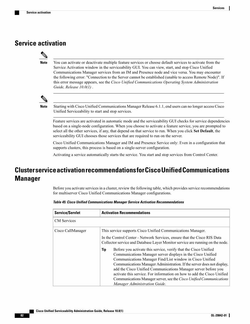
Service activation
You can activate or deactivate multiple feature services or choose default services to activate from theService Activation window in the serviceability GUI. You can view, start, and stop Cisco UnifiedCommunications Manager services from an IM and Presence node and vice versa. You may encounterthe following error: "Connection to the Server cannot be established (unable to access Remote Node)". Ifthis error message appears, see the Cisco Unified Communications Operating System AdministrationGuide, Release 10.0(1) .
Note
Starting with Cisco Unified CommunicationsManager Release 6.1.1, end users can no longer access CiscoUnified Serviceability to start and stop services.
Note
Feature services are activated in automatic mode and the serviceability GUI checks for service dependenciesbased on a single-node configuration. When you choose to activate a feature service, you are prompted toselect all the other services, if any, that depend on that service to run. When you click Set Default, theserviceability GUI chooses those services that are required to run on the server.
Cisco Unified Communications Manager and IM and Presence Service only: Even in a configuration thatsupports clusters, this process is based on a single-server configuration.
Activating a service automatically starts the service. You start and stop services from Control Center.
Cluster service activation recommendations for Cisco Unified CommunicationsManager
Before you activate services in a cluster, review the following table, which provides service recommendationsfor multiserver Cisco Unified Communications Manager configurations.
Table 45: Cisco Unified Communications Manager Service Activation Recommendations
Activation RecommendationsService/Servlet
CM Services
This service supports Cisco Unified Communications Manager.
In the Control Center - Network Services, ensure that the Cisco RIS DataCollector service and Database LayerMonitor service are running on the node.
Before you activate this service, verify that the Cisco UnifiedCommunications Manager server displays in the Cisco UnifiedCommunications Manager Find/List window in Cisco UnifiedCommunicationsManager Administration. If the server does not display,add the Cisco Unified Communications Manager server before youactivate this service. For information on how to add the Cisco UnifiedCommunicationsManager server, see theCiscoUnified CommunicationsManager Administration Guide.
Tip
Cisco CallManager
Cisco Unified Serviceability Administration Guide, Release 10.0(1)82 OL-29842-01
ServicesService activation

Activation RecommendationsService/Servlet
Activate only if using an SMDI integration to a third-party Voicemail systemusing a server-attached USB-to-serial adapter.
Cisco Messaging Interface
For mobile voice access to work, you must activate this service on the firstnode in the cluster after you configure the H.323 gateway to point to the firstVXML page. In addition, make sure that the Cisco CallManager and the CiscoTFTP services run on one server in the cluster, not necessarily the same serverwhere the Cisco Unified Mobile Voice Access Service runs.
Cisco Unified MobileVoice Access Service
If you have more than one node in the cluster, activate on one or two serversper cluster. You may activate on a node that is dedicated specifically for musicon hold. This service requires that you activate Cisco TFTP on one node in thecluster. Do not activate this service on the first node or on any nodes that runthe Cisco CallManager service.
Cisco IP Voice MediaStreaming App
Activate on each node to which JTAPI/TAPI applications will connect.CTIManager activation requires the Cisco CallManager service also to beactivated on the node. See topics related to CM services for more informationon CTIManager and Cisco CallManager services interaction.
Cisco CTIManager
Activate on all nodes in the cluster.Cisco Extension Mobility
Activate this service, which supports the Quality Report Tool (QRT), on oneor more servers that run the Cisco RIS Data Collector. Make sure that youactivate the Cisco CTIManager service on a node in the cluster.
Cisco Extended Functions
When the DHCPMonitor service is enabled, it detects changes in the databasethat affect IP addresses for the IP phones, modifies the /etc/dhcpd.conf file,and stops and restarts the DHCPD daemon with the updated configuration file.Activate this service on the node that has DHCP enabled.
Cisco DHCP MonitorService
If you plan to use Cisco Location Call Admission Control functionality tomanage bandwidth allocation for audio and video calls, you must activate thisservice. This service works in conjunction with the Cisco CallManager service.It is recommended to run the Cisco Location Bandwidth Manager on the sameserver that runs the Cisco CallManager service. If the Location BandwidthManager is not running on the same server as the CallManager service, ensurethat you configure the Location Bandwidth Manager Group correctly.
Cisco Location BandwidthManager
If you plan to propagate the URI and numeric routing information betweenmultiple Cisco Unified Communications Manager clusters, you must activatethis service on the publisher of the cluster that participates in this exchange.
Cisco Intercluster LookupService
If you have more than one node in the cluster, activate this service on one nodethat is dedicated specifically for the Cisco Dialed Number Analyzer service.
Cisco Dialed NumberAnalyzer Server
Cisco Unified Serviceability Administration Guide, Release 10.0(1) OL-29842-01 83
ServicesCluster service activation recommendations for Cisco Unified Communications Manager

Activation RecommendationsService/Servlet
If you are planning to use Cisco Unified Communications Manager DialedNumber Analyzer, activate this service. This service may consume a lot ofresources, so only activate this service on the node with the least amount ofcall-processing activity or during off-peak hours.
Cisco Dialed NumberAnalyzer
If you have more than one node in the cluster, activate this service on one nodethat is dedicated specifically for the Cisco TFTP service. Configure Option150 if you activate this service on more than one node in the cluster.
Cisco TFTP
CTI Services
If you are planning to use Cisco Unified Communications Manager Assistant,activate this service on any two servers (Primary and Backup) in the cluster.Ensure that Cisco CTIManager service is activated in the cluster. See theCiscoUnified Communications Manager Features and Services Guide for otherrecommendations.
Cisco IPManager Assistant
Activate on one node per cluster.Cisco WebDialer WebService
To enable the Self-Provisioning IVR service, you must also enable the CiscoCTI Manager service.
You can configure self-provisioning even if the service is deactivated, but theadministrator cannot assign IP phones to users using the IVR service. By default,this service is deactivated.
Self-Provisioning IVR
CDR Services
You can activate the Cisco SOAP-CDROnDemand Service only on the firstserver, and it requires that the Cisco CDRRepositoryManager and Cisco CDRAgent services are running on the same server.
CiscoSOAP-CDRonDemandService
You can activate the Cisco CAR Web Service only on the first server, and itrequires that the Cisco CAR Scheduler service is activated and running on thesame server and that the CDR Repository Manager service also is running onthe same server.
Cisco CAR Web Service
Database and Admin Services
Following installation, Cisco AXL Web Service is enabled by default on allcluster nodes. Cisco recommends that you always leave the service activatedon the publisher node. This ensures that you are able to configure products thatare dependent on AXL, such as Unified Provisioning Manager.
Based on your needs, you can activate or deactivate the service on specificsubscriber nodes in Cisco Unified Serviceability under Feature Services.
Cisco AXL Web Service
Cisco Unified Serviceability Administration Guide, Release 10.0(1)84 OL-29842-01
ServicesCluster service activation recommendations for Cisco Unified Communications Manager

Activation RecommendationsService/Servlet
You can activate the Cisco Bulk Provisioning Service only on the first node.If you use the Bulk Administration Tool (BAT) to administer phones and users,you must activate this service.
Cisco Bulk ProvisioningService
This service performs authentication and user authorization checks. TheTabSync client in Cisco IP Phone Address Book Synchronizer uses the CiscoUXLWeb Service for queries to the Cisco Unified Communications Managerdatabase.
If you plan to use the Cisco IP Phone Address Book Synchronizer, you mustactivate this service on one node, preferably publisher. If you are not usingCisco IP Phone Address Book Synchronizer, then Cisco recommends that youdeactivate this service . By default, this service is deactivated.
Cisco UXL Web Service
You must activate this service if you plan to use a Cisco Prime CollaborationDeployment (PCD) server to manage upgrades, switch version, restart orreaddress operations. Platform Administrative Web Service (PAWS) allowsSOAP communication between the Call Manager and Prime CollaborationDeployment (PCD). If you have more than one node in the cluster, you mustactivate this service on each server in the cluster.
Cisco PlatformAdministrative WebService
Before you can use the Cisco Unified CommunicationsManager Auto-RegisterPhone Tool, you must activate this service on the first node. When you createdummy MAC addresses for the Cisco Unified Communications ManagerAuto-Register Phone Tool, ensure that the Cisco Bulk Provisioning Service isactivated on the same node.
Cisco TAPS Service
Performance and Monitoring Services
Activate on only the first node.
The service only generates reports on the first node even if you activatethe service on other nodes.
Note
Cisco ServiceabilityReporter
If you use SNMP, activate this service on all servers in the cluster.Cisco CallManager SNMPService
Security Services
Activate on all servers in the cluster.Cisco CTL Provider
Activate on only the first node.Cisco Certificate AuthorityProxy Function (CAPF)
Directory Services
Activate only on the first node.Cisco DirSync
Cisco Unified Serviceability Administration Guide, Release 10.0(1) OL-29842-01 85
ServicesCluster service activation recommendations for Cisco Unified Communications Manager

Cluster service activation recommendations for IM and Presence Service
Before you turn on any services for a feature, you must complete all the required configuration on IM andPresence for that feature. See the relevant documentation for each IM and Presence feature.
Caution
Before you turn on services in a cluster, review the following table, which provides service recommendationsfor multinode IM and Presence configurations.
Table 46: IM and Presence Service Activation Recommendations
RecommendationsService/Servlet
Database and Admin Services
Following installation, Cisco AXL Web Service isenabled by default on all cluster nodes. Ciscorecommends that you always leave the serviceactivated on the IM and Presence database publishernode. This ensures that you are able to configureproducts that are dependent on AXL.
Based on your needs, you can activate or deactivatethe service on specific IM and Presence subscribernodes in Cisco Unified Serviceability under FeatureServices.
Cisco AXL Web Service
• You turn on the Cisco Bulk ProvisioningService only on the first node.
• If you use the Bulk Administration Tool (BAT)to administer users, you must turn on thisservice.
Cisco Bulk Provisioning Service
Performance and Monitoring Services
Turn on this service on the publisher node only.The service only generates reports on thepublisher node even if you turn on theservice on other nodes.
NoteCisco Serviceability Reporter
IM and Presence Services
Turn on this service on all nodes in the cluster.Cisco SIP Proxy
Turn on this service on all nodes in the cluster.Cisco Presence Engine
Turn on this service on all nodes in the cluster.Cisco Sync Agent
Cisco Unified Serviceability Administration Guide, Release 10.0(1)86 OL-29842-01
ServicesCluster service activation recommendations for IM and Presence Service
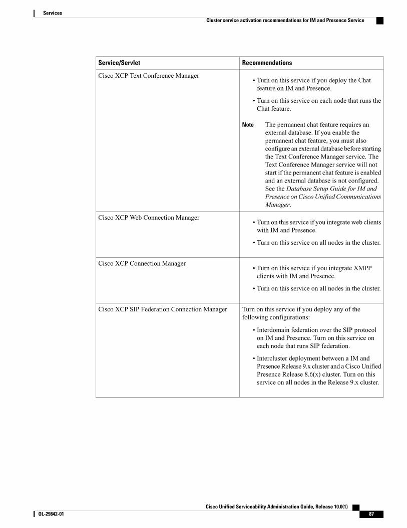
RecommendationsService/Servlet
• Turn on this service if you deploy the Chatfeature on IM and Presence.
• Turn on this service on each node that runs theChat feature.
The permanent chat feature requires anexternal database. If you enable thepermanent chat feature, you must alsoconfigure an external database before startingthe Text Conference Manager service. TheText Conference Manager service will notstart if the permanent chat feature is enabledand an external database is not configured.See the Database Setup Guide for IM andPresence on Cisco Unified CommunicationsManager.
Note
Cisco XCP Text Conference Manager
• Turn on this service if you integrate web clientswith IM and Presence.
• Turn on this service on all nodes in the cluster.
Cisco XCP Web Connection Manager
• Turn on this service if you integrate XMPPclients with IM and Presence.
• Turn on this service on all nodes in the cluster.
Cisco XCP Connection Manager
Turn on this service if you deploy any of thefollowing configurations:
• Interdomain federation over the SIP protocolon IM and Presence. Turn on this service oneach node that runs SIP federation.
• Intercluster deployment between a IM andPresence Release 9.x cluster and a CiscoUnifiedPresence Release 8.6(x) cluster. Turn on thisservice on all nodes in the Release 9.x cluster.
Cisco XCP SIP Federation Connection Manager
Cisco Unified Serviceability Administration Guide, Release 10.0(1) OL-29842-01 87
ServicesCluster service activation recommendations for IM and Presence Service
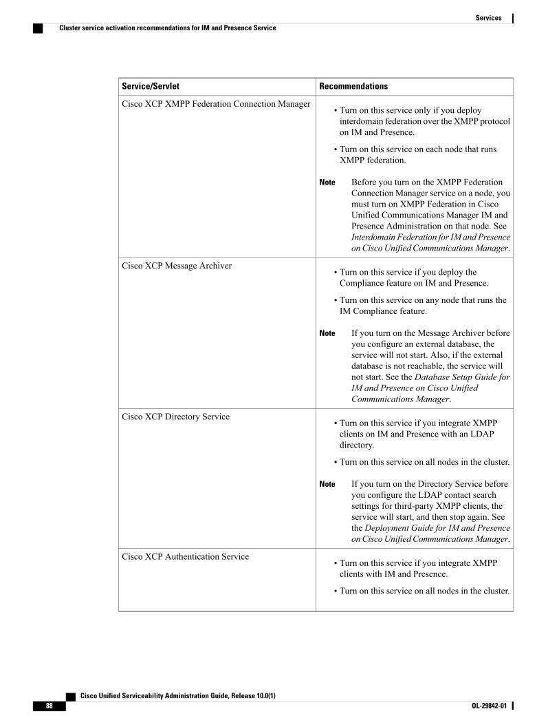
RecommendationsService/Servlet
• Turn on this service only if you deployinterdomain federation over the XMPP protocolon IM and Presence.
• Turn on this service on each node that runsXMPP federation.
Before you turn on the XMPP FederationConnection Manager service on a node, youmust turn on XMPP Federation in CiscoUnified Communications Manager IM andPresence Administration on that node. SeeInterdomain Federation for IM and Presenceon CiscoUnified CommunicationsManager.
Note
Cisco XCP XMPP Federation Connection Manager
• Turn on this service if you deploy theCompliance feature on IM and Presence.
• Turn on this service on any node that runs theIM Compliance feature.
If you turn on the Message Archiver beforeyou configure an external database, theservice will not start. Also, if the externaldatabase is not reachable, the service willnot start. See the Database Setup Guide forIM and Presence on Cisco UnifiedCommunications Manager.
Note
Cisco XCP Message Archiver
• Turn on this service if you integrate XMPPclients on IM and Presence with an LDAPdirectory.
• Turn on this service on all nodes in the cluster.
If you turn on the Directory Service beforeyou configure the LDAP contact searchsettings for third-party XMPP clients, theservice will start, and then stop again. Seethe Deployment Guide for IM and Presenceon CiscoUnified CommunicationsManager.
Note
Cisco XCP Directory Service
• Turn on this service if you integrate XMPPclients with IM and Presence.
• Turn on this service on all nodes in the cluster.
Cisco XCP Authentication Service
Cisco Unified Serviceability Administration Guide, Release 10.0(1)88 OL-29842-01
ServicesCluster service activation recommendations for IM and Presence Service
Activate feature servicesYou activate and deactivate feature services in the Service Activation window in the serviceability GUI.Services that display in the Service Activation window do not start until you activate them.
You can activate and deactivate only features services (not network services). You may activate or deactivateas many services as you want at the same time. Some feature services depend on other services, and thedependent services get activated before the feature service activates.
Cisco Unified Communications Manager and IM and Presence Service only: Before you activate servicesin the Service Activation window, review topics related to cluster service activation recommendations.
Tip
Procedure
Step 1 Choose Tools > Service Activation.The Service Activation window displays.
Step 2 Select the server (node) from the Server list box, and then select Go.You can access Cisco Unified Communications Manager services from an IM and Presence Service node andvice versa. You may encounter the following error when trying to access a remote node: "Connection to theServer cannot be established (unable to connect to Remote Node)". If this error message appears, see theCiscoUnified Communications Operating System Administration Guide, Release 10.0(1).
Step 3 Perform one of the following actions to turn on or turn off services:a) To turn on the default services required to run on a single server, select Set to Default.
This option selects default services based on the configuration of a single server, and checks forservice dependencies.
Note
b) To turn on all services, check Check All Services.c) To turn on a specific service, check the service that you want to turn ond) To turn off a service, uncheck the services that you want to turn off.
Step 4 Cisco Unified Communications Manager and IM and Presence Service only: For a cluster configuration,review the cluster service activation recommendations, and then check the check boxes next to the servicesthat you want to activate.
Step 5 After you check the check boxes for the services that you want to activate, click Save.To deactivate services that you activated, uncheck the check boxes next to the services that you wantto deactivate; then, click Save.
Tip
To obtain the latest status of the services, click theRefresh button.Tip
Related Topics
Cluster service activation recommendations for Cisco Unified Communications Manager, on page 82Cluster service activation recommendations for IM and Presence Service, on page 86
Cisco Unified Serviceability Administration Guide, Release 10.0(1) OL-29842-01 89
ServicesActivate feature services

Start, stop, and restart services in Control Center or CLITo perform these tasks, the serviceability GUI provides two Control Center windows. To start, stop, andrestart network services, access the Control Center—Network Services window. To start, stop, and restartfeature services, access the Control Center—Feature Services window.
Use the Related Links list box and the Go button to navigate to Control Center and Service Activationwindows.
Tip
Start, stop, and restart services in Control CenterControl Center in the serviceability GUI allows you to:
• view status
• refresh status
• start, stop, and restart feature and network services on a particular server, or for a server in a cluster ina cluster configuration
When a service is stopping, you cannot start it until after the service is stopped.
Cisco Unified CommunicationsManager only: Stopping a service also stops call processing for all devicesthat the service controls. When a service is stopped, calls from an IP phone to another IP phone remainconnected; calls in progress from an IP phone to a Media Gateway Control Protocol (MGCP) gatewayalso remain connected, but other types of calls get dropped.
Caution
Procedure
Step 1 Depending on the service type that you want to start/stop/restart/refresh, perform one of the following tasks:
• Choose Tools > Control Center - Feature Services.Before you can start, stop, or restart a feature service, it must be activated.Tip
• Choose Tools > Control Center - Network Services.
Step 2 Choose the server from the Server drop-down list box, and then click Go.The window displays the following items:
• The service names for the server that you chose.
• The service group.
• The service status, for example, Started, Running, Not Running, and so on. (Status column)
• The exact time that the service started running. (Start Time column)
• The amount of time that the service has been running. (Up Time column)
Cisco Unified Serviceability Administration Guide, Release 10.0(1)90 OL-29842-01
ServicesStart, stop, and restart services in Control Center or CLI
Step 3 Perform one of the following tasks:
• Click the button next to the service that you want to start, and then click Start. The Status changes toreflect the updated status.
• Click the button next to the service that you want to stop, and then click Stop. The Status changes toreflect the updated status.
• Click the button next to the service that you want to restart, and then clickRestart. A message indicatesthat restarting may take a while. Click OK.
• Click Refresh to get the latest status of the services.
• To go to the Service Activation window or to the other Control Center window, choose an option fromthe Related Links drop-down list box, and then click Go.
Start, stop, and restart services using command line interfaceYou can start and stop some services through the CLI. For a list of services that you can start and stop throughthe CLI and for information on how to perform these tasks, refer to the Command Line Interface ReferenceGuide for Cisco Unified Solutions.
You must start and stop most services from Control Center in the serviceability GUI.Tip
Cisco Unified Serviceability Administration Guide, Release 10.0(1) OL-29842-01 91
ServicesStart, stop, and restart services in Control Center or CLI

Cisco Unified Serviceability Administration Guide, Release 10.0(1)92 OL-29842-01
ServicesStart, stop, and restart services in Control Center or CLI
C H A P T E R 6Tools and Reports
• Serviceability Reports Archive, page 93
• CDR Repository Manager, page 113
• Audit logs, page 118
• Locations, page 128
Serviceability Reports ArchiveThe Cisco Serviceability Reporter service generates daily reports containing charts that display a summaryof the statistics for that particular report. Reporter generates reports once a day on the basis of loggedinformation.
Using the serviceability GUI, view reports from Tools > Serviceability Reports Archive. You must activatethe Cisco Serviceability Reporter service before you can view reports. After you activate the service, reportgeneration may take up to 24 hours.
The reports contain 24-hour data for the previous day. A suffix that is added to the report names shows thedate for which Reporter generated them; for example, AlertRep_mm_dd_yyyy.pdf. The Serviceability ReportsArchive window uses this date to display the reports for the relevant date only. The reports generate from thedata that is present in the log files, with the timestamp for the previous day. The system considers log filesfor the current date and the previous two days for collecting data.
The time that is shown in the report reflects the server “System Time.”You can retrieve log files from the server while you are generating reports.
The Cisco Unified Reporting web application provides snapshot views of data into one output and runsdata checks. The application also allows you to archive generated reports. See theCisco Unified ReportingAdministration Guide for more information.
Note
Serviceability Report Archive considerations for cluster configurations
This section applies to Cisco Unified Communications Manager and IM and Presence Service only.
Cisco Unified Serviceability Administration Guide, Release 10.0(1) OL-29842-01 93
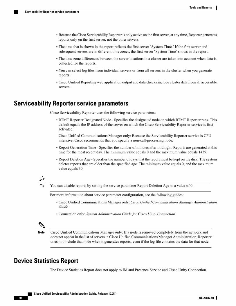
• Because the Cisco Serviceability Reporter is only active on the first server, at any time, Reporter generatesreports only on the first server, not the other servers.
• The time that is shown in the report reflects the first server “System Time.” If the first server andsubsequent servers are in different time zones, the first server “System Time” shows in the report.
• The time zone differences between the server locations in a cluster are taken into account when data iscollected for the reports.
• You can select log files from individual servers or from all servers in the cluster when you generatereports.
• Cisco Unified Reporting web application output and data checks include cluster data from all accessibleservers.
Serviceability Reporter service parametersCisco Serviceability Reporter uses the following service parameters:
• RTMT Reporter Designated Node - Specifies the designated node on which RTMT Reporter runs. Thisdefault equals the IP address of the server on which the Cisco Serviceability Reporter service is firstactivated.
Cisco Unified Communications Manager only: Because the Serviceability Reporter service is CPUintensive, Cisco recommends that you specify a non-call-processing node.
• Report Generation Time - Specifies the number of minutes after midnight. Reports are generated at thistime for the most recent day. The minimum value equals 0 and the maximum value equals 1439.
• Report Deletion Age - Specifies the number of days that the report must be kept on the disk. The systemdeletes reports that are older than the specified age. The minimum value equals 0, and the maximumvalue equals 30.
You can disable reports by setting the service parameter Report Deletion Age to a value of 0.Tip
For more information about service parameter configuration, see the following guides:
• Cisco Unified CommunicationsManager only:Cisco Unified CommunicationsManager AdministrationGuide
• Connection only: System Administration Guide for Cisco Unity Connection
Cisco Unified Communications Manager only: If a node is removed completely from the network anddoes not appear in the list of servers in Cisco Unified CommunicationsManager Administration, Reporterdoes not include that node when it generates reports, even if the log file contains the data for that node.
Note
Device Statistics ReportThe Device Statistics Report does not apply to IM and Presence Service and Cisco Unity Connection.
Cisco Unified Serviceability Administration Guide, Release 10.0(1)94 OL-29842-01
Tools and ReportsServiceability Reporter service parameters

The Device Statistics Report provides the following line charts:
• Number of Registered Phones per Server
• Number of H.323 Gateways in the Cluster
• Number of Trunks in the Cluster
Number of Registered Phones per Server
A line chart displays the number of registered phones for each Cisco Unified CommunicationsManager server(and cluster in a Cisco Unified Communications Manager cluster configuration). Each line in the chartrepresents the data for a server for which data is available, and one extra line displays the clusterwide data(Cisco Unified Communications Manager clusters only). Each data value in the chart represents the averagenumber of phones that are registered for a 15-minute duration. If a server shows no data, Reporter does notgenerate the line that represents that server. If no data exists for the server (or for all servers in a Cisco UnifiedCommunications Manager cluster configuration), for registered phones, Reporter does not generate the chart.The message “No data for Device Statistics report available” displays.
The following figure shows an example of a line chart representing the number of registered phones per CiscoUnified CommunicationsManager server in a Cisco Unified CommunicationsManager cluster configuration.
Figure 1: Line Chart That Depicts Number of Registered Phones Per Server
Number of MGCP Gateways Registered in the Cluster
A line chart displays the number of registered MGCP FXO, FXS, PRI, and T1CAS gateways. Each linerepresents data only for the Cisco Unified Communications Manager server (or cluster in a Cisco UnifiedCommunications Manager cluster configuration); so, four lines show server (or clusterwide) details for eachgateway type. Each data value in the chart represents the average number ofMGCP gateways that are registeredfor a 15-minute duration. If no data exists for a gateway for the server (or all the servers in a cluster), Reporterdoes not generate the line that represents data for that particular gateway. If no data exists for all gatewaysfor the server (or for all servers in a cluster), Reporter does not generate the chart.
Cisco Unified Serviceability Administration Guide, Release 10.0(1) OL-29842-01 95
Tools and ReportsDevice Statistics Report
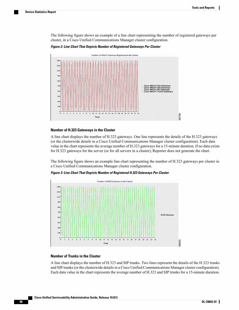
The following figure shows an example of a line chart representing the number of registered gateways percluster, in a Cisco Unified Communications Manager cluster configuration.
Figure 2: Line Chart That Depicts Number of Registered Gateways Per Cluster
Number of H.323 Gateways in the Cluster
A line chart displays the number of H.323 gateways. One line represents the details of the H.323 gateways(or the clusterwide details in a Cisco Unified Communications Manager cluster configuration). Each datavalue in the chart represents the average number of H.323 gateways for a 15-minute duration. If no data existsfor H.323 gateways for the server (or for all servers in a cluster), Reporter does not generate the chart.
The following figure shows an example line chart representing the number of H.323 gateways per cluster ina Cisco Unified Communications Manager cluster configuration.
Figure 3: Line Chart That Depicts Number of Registered H.323 Gateways Per Cluster
Number of Trunks in the Cluster
A line chart displays the number of H.323 and SIP trunks. Two lines represent the details of the H.323 trunksand SIP trunks (or the clusterwide details in a Cisco Unified CommunicationsManager cluster configuration).Each data value in the chart represents the average number of H.323 and SIP trunks for a 15-minute duration.
Cisco Unified Serviceability Administration Guide, Release 10.0(1)96 OL-29842-01
Tools and ReportsDevice Statistics Report
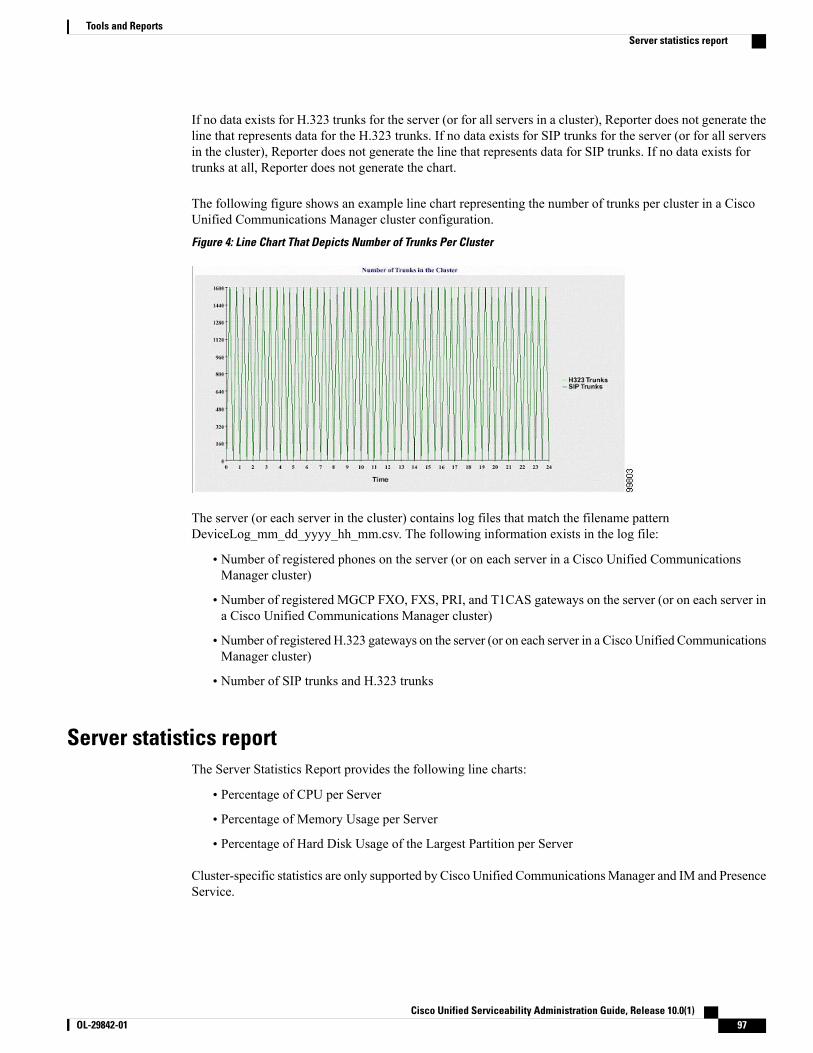
If no data exists for H.323 trunks for the server (or for all servers in a cluster), Reporter does not generate theline that represents data for the H.323 trunks. If no data exists for SIP trunks for the server (or for all serversin the cluster), Reporter does not generate the line that represents data for SIP trunks. If no data exists fortrunks at all, Reporter does not generate the chart.
The following figure shows an example line chart representing the number of trunks per cluster in a CiscoUnified Communications Manager cluster configuration.
Figure 4: Line Chart That Depicts Number of Trunks Per Cluster
The server (or each server in the cluster) contains log files that match the filename patternDeviceLog_mm_dd_yyyy_hh_mm.csv. The following information exists in the log file:
• Number of registered phones on the server (or on each server in a Cisco Unified CommunicationsManager cluster)
• Number of registered MGCP FXO, FXS, PRI, and T1CAS gateways on the server (or on each server ina Cisco Unified Communications Manager cluster)
• Number of registered H.323 gateways on the server (or on each server in a Cisco Unified CommunicationsManager cluster)
• Number of SIP trunks and H.323 trunks
Server statistics reportThe Server Statistics Report provides the following line charts:
• Percentage of CPU per Server
• Percentage of Memory Usage per Server
• Percentage of Hard Disk Usage of the Largest Partition per Server
Cluster-specific statistics are only supported by Cisco Unified CommunicationsManager and IM and PresenceService.
Cisco Unified Serviceability Administration Guide, Release 10.0(1) OL-29842-01 97
Tools and ReportsServer statistics report
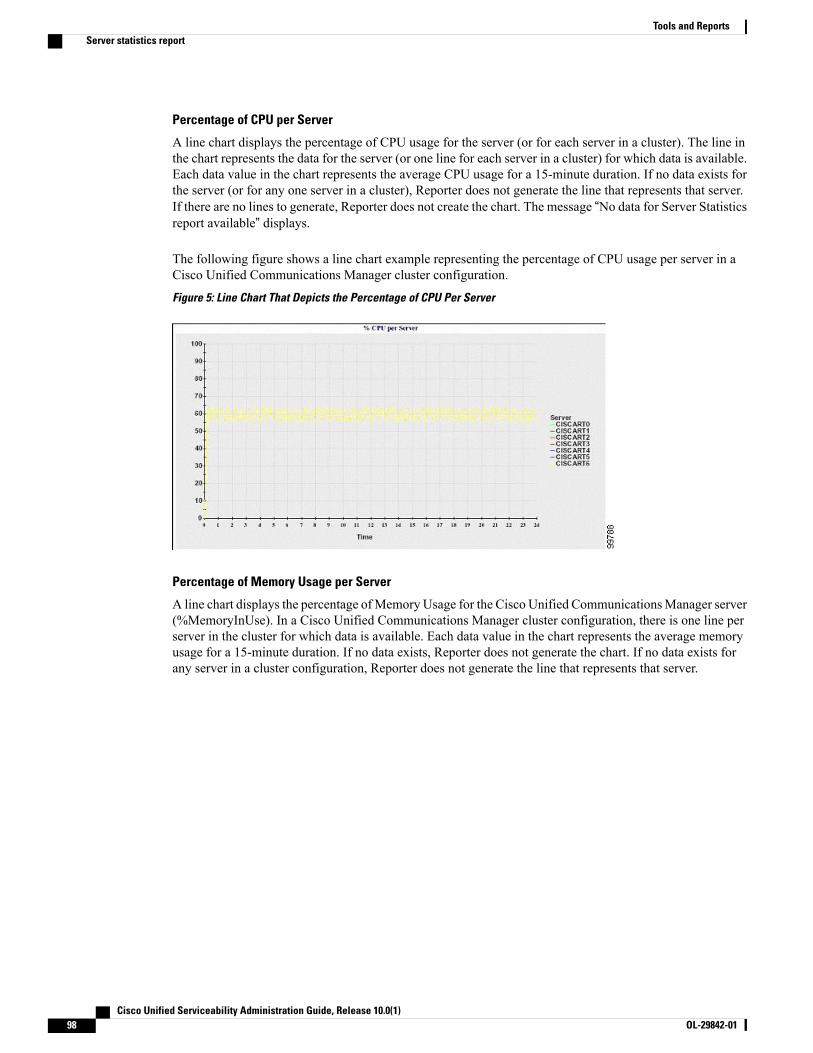
Percentage of CPU per Server
A line chart displays the percentage of CPU usage for the server (or for each server in a cluster). The line inthe chart represents the data for the server (or one line for each server in a cluster) for which data is available.Each data value in the chart represents the average CPU usage for a 15-minute duration. If no data exists forthe server (or for any one server in a cluster), Reporter does not generate the line that represents that server.If there are no lines to generate, Reporter does not create the chart. The message “No data for Server Statisticsreport available” displays.
The following figure shows a line chart example representing the percentage of CPU usage per server in aCisco Unified Communications Manager cluster configuration.
Figure 5: Line Chart That Depicts the Percentage of CPU Per Server
Percentage of Memory Usage per Server
A line chart displays the percentage ofMemory Usage for the Cisco Unified CommunicationsManager server(%MemoryInUse). In a Cisco Unified Communications Manager cluster configuration, there is one line perserver in the cluster for which data is available. Each data value in the chart represents the average memoryusage for a 15-minute duration. If no data exists, Reporter does not generate the chart. If no data exists forany server in a cluster configuration, Reporter does not generate the line that represents that server.
Cisco Unified Serviceability Administration Guide, Release 10.0(1)98 OL-29842-01
Tools and ReportsServer statistics report
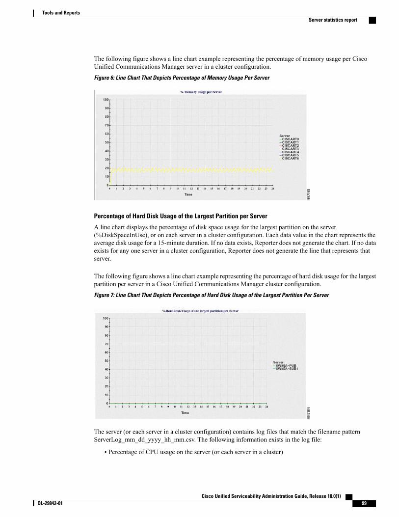
The following figure shows a line chart example representing the percentage of memory usage per CiscoUnified Communications Manager server in a cluster configuration.
Figure 6: Line Chart That Depicts Percentage of Memory Usage Per Server
Percentage of Hard Disk Usage of the Largest Partition per Server
A line chart displays the percentage of disk space usage for the largest partition on the server(%DiskSpaceInUse), or on each server in a cluster configuration. Each data value in the chart represents theaverage disk usage for a 15-minute duration. If no data exists, Reporter does not generate the chart. If no dataexists for any one server in a cluster configuration, Reporter does not generate the line that represents thatserver.
The following figure shows a line chart example representing the percentage of hard disk usage for the largestpartition per server in a Cisco Unified Communications Manager cluster configuration.
Figure 7: Line Chart That Depicts Percentage of Hard Disk Usage of the Largest Partition Per Server
The server (or each server in a cluster configuration) contains log files that match the filename patternServerLog_mm_dd_yyyy_hh_mm.csv. The following information exists in the log file:
• Percentage of CPU usage on the server (or each server in a cluster)
Cisco Unified Serviceability Administration Guide, Release 10.0(1) OL-29842-01 99
Tools and ReportsServer statistics report

• Percentage of Memory usage (%MemoryInUse) on the server (or on each server in a cluster)
• Percentage of Hard disk usage of the largest partition (%DiskSpaceInUse) on the server (or on eachserver in a cluster)
Service Statistics ReportThe Service Statistics Report does not support IM and Presence Service and Cisco Unity Connection.
The Service Statistics Report provides the following line charts:
• Cisco CTI Manager: Number of Open Devices
• Cisco CTI Manager: Number of Open Lines
• Cisco TFTP: Number of Requests
• Cisco TFTP: Number of Aborted Requests
Cisco CTI Manager: Number of Open Devices
A line chart displays the number of CTI Open Devices for the CTI Manager (or for each CTI Manager in aCisco Unified Communications Manager cluster configuration). Each line chart represents the data for theserver (or on each server in a Cisco Unified Communications Manager cluster) on which service is activated.Each data value in the chart represents the average number of CTI open devices for a 15-minute duration. Ifno data exists, Reporter does not generate the chart. If no data exists for any one server in a Cisco UnifiedCommunicationsManager cluster configuration, Reporter does not generate the line that represents that server.The message “No data for Service Statistics report available” displays.
The following figure shows a line chart example representing the number of open devices per Cisco CTIManager in a Cisco Unified Communications Manager cluster configuration.
Figure 8: Line Chart That Depicts Cisco CTI Manager: Number of Open Devices
Cisco CTI Manager: Number of Open Lines
A line chart displays the number of CTI open lines for the CTI Manager (or per CTI Manager in a CiscoUnified Communications Manager cluster configuration). A line in the chart represents the data for the server
Cisco Unified Serviceability Administration Guide, Release 10.0(1)100 OL-29842-01
Tools and ReportsService Statistics Report

(or one line for each server in a Cisco Unified Communications Manager cluster configuration) where theCisco CTI Manager service is activated. Each data value in the chart represents the average number of CTIopen lines for a 15-minute duration. If no data exists, Reporter does not generate the chart. If no data existsfor any one server in a Cisco Unified Communications Manager cluster configuration, Reporter does notgenerate the line that represents that server.
The followings figure shows a line chart example representing the number of open lines per Cisco CTIManagerin a Cisco Unified Communications Manager cluster configuration.
Figure 9: Line Chart That Depicts Cisco CTI Manager: Number of Open Lines
Cisco TFTP: Number of Requests
A line chart displays the number of Cisco TFTP requests for the TFTP server (or per TFTP server in a CiscoUnified Communications Manager cluster configuration). A line in the chart represents the data for the server(or one line for each server in a Cisco Unified Communications Manager cluster) where the Cisco TFTPservice is activated. Each data value in the chart represents the average number of TFTP requests for a 15-minuteduration. If no data exists, Reporter does not generate the chart. If no data exists for any one server in a CiscoUnified Communications Manager cluster configuration, Reporter does not generate the line that representsthat server.
Cisco Unified Serviceability Administration Guide, Release 10.0(1) OL-29842-01 101
Tools and ReportsService Statistics Report
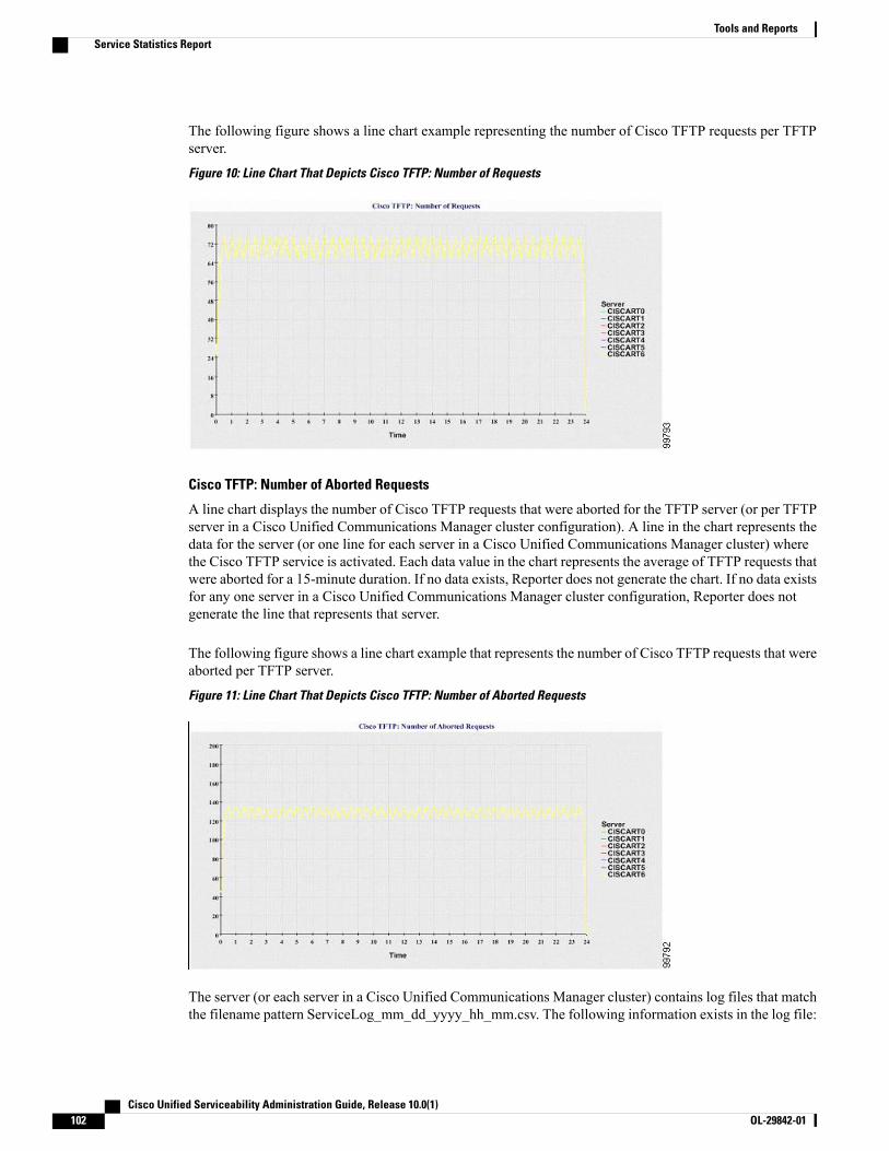
The following figure shows a line chart example representing the number of Cisco TFTP requests per TFTPserver.
Figure 10: Line Chart That Depicts Cisco TFTP: Number of Requests
Cisco TFTP: Number of Aborted Requests
A line chart displays the number of Cisco TFTP requests that were aborted for the TFTP server (or per TFTPserver in a Cisco Unified Communications Manager cluster configuration). A line in the chart represents thedata for the server (or one line for each server in a Cisco Unified Communications Manager cluster) wherethe Cisco TFTP service is activated. Each data value in the chart represents the average of TFTP requests thatwere aborted for a 15-minute duration. If no data exists, Reporter does not generate the chart. If no data existsfor any one server in a Cisco Unified Communications Manager cluster configuration, Reporter does notgenerate the line that represents that server.
The following figure shows a line chart example that represents the number of Cisco TFTP requests that wereaborted per TFTP server.
Figure 11: Line Chart That Depicts Cisco TFTP: Number of Aborted Requests
The server (or each server in a Cisco Unified Communications Manager cluster) contains log files that matchthe filename pattern ServiceLog_mm_dd_yyyy_hh_mm.csv. The following information exists in the log file:
Cisco Unified Serviceability Administration Guide, Release 10.0(1)102 OL-29842-01
Tools and ReportsService Statistics Report

• For each CTI Manager - Number of open devices
• For each CTI Manager - Number of open lines
• For each Cisco TFTP server - TotalTftpRequests
• For each Cisco TFTP server - TotalTftpRequestsAborted
Call activities reportThe Call Activities Report does not support IM and Presence Service and Cisco Unity Connection.
The Call Activities Report provides the following line charts:
• Cisco Unified Communications Manager Call Activity for a cluster
• H.323 Gateways Call Activity for the Cluster
• MGCP Gateways Call Activity for the Cluster
• MGCP Gateways
• Trunk Call Activity for the Cluster
Cisco Unified Communications Manager Call Activity for the Cluster
A line chart displays the number of Cisco Unified Communications Manager calls that were attempted andcalls that were completed. In a Cisco Unified Communications Manager cluster configuration, the line chartdisplays the number of calls attempted and completed for the entire cluster. The chart comprises two lines,one for the number of calls that were attempted and another for the number of calls that were completed. Fora Cisco Unified CommunicationsManager cluster configuration, each line represents the cluster value, whichis the sum of the values for all the servers in the cluster (for which data is available). Each data value in thechart represents the total number of calls that were attempted or calls that were completed for a 15-minuteduration.
If no data exists for Cisco Unified Communications Manager calls that were completed, Reporter does notgenerate the line that represents data for the calls that were completed. If no data exists for Cisco UnifiedCommunications Manager calls that were attempted, Reporter does not generate the line that represents datafor the calls that were attempted. In a Cisco Unified Communications Manager cluster configuration, if nodata exists for a server in the cluster, Reporter does not generate the line that represents calls attempted orcompleted on that server. If no data exists for Cisco Unified Communications Manager call activities at all,Reporter does not generate the chart. The message “No data for Call Activities report available” displays.
Cisco Unified Serviceability Administration Guide, Release 10.0(1) OL-29842-01 103
Tools and ReportsCall activities report

The following figure shows a line chart representing the number of attempted and completed calls for a CiscoUnified Communications Manager cluster.
Figure 12: Line Chart That Depicts Cisco Unified Communications Manager Call Activity for a Cluster
H.323 Gateways Call Activity for the Cluster
A line chart displays the number of calls that were attempted and calls that were completed for H.323 gateways.In a Cisco Unified CommunicationsManager cluster configuration, the line chart displays the number of callsattempted and completed for the entire cluster. The chart comprises two lines, one for the number of calls thatwere attempted and another for the number of calls that were completed. For a Cisco Unified CommunicationsManager cluster configuration, each line represents the cluster value, which equals the sum of the values forall the servers in the cluster (for which data is available). Each data value in the chart represents the totalnumber of calls that were attempted or calls that were completed for a 15-minute duration. If no data existsfor H.323 gateways calls that were completed, Reporter does not generate the line that represents data forcalls that were completed. If no data exists for H.323 gateways calls that were attempted, Reporter does notgenerate the line that represents data for calls that were attempted. In a Cisco Unified CommunicationsManagercluster configuration, if no data exists for a server in the cluster, Reporter does not generate the line thatrepresents calls attempted or completed on that server. If no data exists for H.323 gateways call activities atall, Reporter does not generate the chart.
Cisco Unified Serviceability Administration Guide, Release 10.0(1)104 OL-29842-01
Tools and ReportsCall activities report
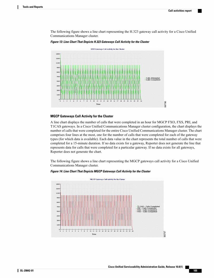
The following figure shows a line chart representing the H.323 gateway call activity for a Cisco UnifiedCommunications Manager cluster.
Figure 13: Line Chart That Depicts H.323 Gateways Call Activity for the Cluster
MGCP Gateways Call Activity for the Cluster
A line chart displays the number of calls that were completed in an hour for MGCP FXO, FXS, PRI, andT1CAS gateways. In a Cisco Unified Communications Manager cluster configuration, the chart displays thenumber of calls that were completed for the entire Cisco Unified Communications Manager cluster. The chartcomprises four lines at the most, one for the number of calls that were completed for each of the gatewaytypes (for which data is available). Each data value in the chart represents the total number of calls that werecompleted for a 15-minute duration. If no data exists for a gateway, Reporter does not generate the line thatrepresents data for calls that were completed for a particular gateway. If no data exists for all gateways,Reporter does not generate the chart.
The following figure shows a line chart representing the MGCP gateways call activity for a Cisco UnifiedCommunications Manager cluster.
Figure 14: Line Chart That Depicts MGCP Gateways Call Activity for the Cluster
Cisco Unified Serviceability Administration Guide, Release 10.0(1) OL-29842-01 105
Tools and ReportsCall activities report
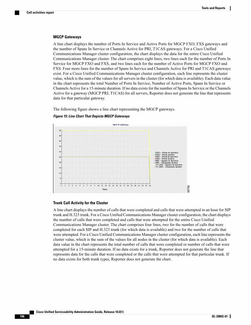
MGCP Gateways
A line chart displays the number of Ports In Service and Active Ports for MGCP FXO, FXS gateways andthe number of Spans In Service or Channels Active for PRI, T1CAS gateways. For a Cisco UnifiedCommunications Manager cluster configuration, the chart displays the data for the entire Cisco UnifiedCommunications Manager cluster. The chart comprises eight lines, two lines each for the number of Ports InService for MGCP FXO and FXS, and two lines each for the number of Active Ports for MGCP FXO andFXS. Four more lines for the number of Spans In Service and Channels Active for PRI and T1CAS gatewaysexist. For a Cisco Unified Communications Manager cluster configuration, each line represents the clustervalue, which is the sum of the values for all servers in the cluster (for which data is available). Each data valuein the chart represents the total Number of Ports In Service, Number of Active Ports, Spans In Service orChannels Active for a 15-minute duration. If no data exists for the number of Spans In Service or the ChannelsActive for a gateway (MGCP PRI, T1CAS) for all servers, Reporter does not generate the line that representsdata for that particular gateway.
The following figure shows a line chart representing the MGCP gateways.
Figure 15: Line Chart That Depicts MGCP Gateways
Trunk Call Activity for the Cluster
A line chart displays the number of calls that were completed and calls that were attempted in an hour for SIPtrunk and H.323 trunk. For a Cisco Unified CommunicationsManager cluster configuration, the chart displaysthe number of calls that were completed and calls that were attempted for the entire Cisco UnifiedCommunications Manager cluster. The chart comprises four lines, two for the number of calls that werecompleted for each SIP and H.323 trunk (for which data is available) and two for the number of calls thatwere attempted. For a Cisco Unified CommunicationsManager cluster configuration, each line represents thecluster value, which is the sum of the values for all nodes in the cluster (for which data is available). Eachdata value in the chart represents the total number of calls that were completed or number of calls that wereattempted for a 15-minute duration. If no data exists for a trunk, Reporter does not generate the line thatrepresents data for the calls that were completed or the calls that were attempted for that particular trunk. Ifno data exists for both trunk types, Reporter does not generate the chart.
Cisco Unified Serviceability Administration Guide, Release 10.0(1)106 OL-29842-01
Tools and ReportsCall activities report

The following figure shows a line chart representing the trunk call activity for a Cisco Unified CommunicationsManager cluster.
Figure 16: Line Chart That Depicts Trunk Call Activity for the Cluster
The server (or each server in a Cisco Unified Communications Manager cluster configuration) contains logfiles that match the filename pattern CallLog_mm_dd_yyyy_hh_mm.csv. The following information existsin the log file:
• Calls that were attempted and calls that were completed for Cisco Unified Communications Manager(or for each server in a Cisco Unified Communications Manager cluster)
• Calls that were attempted and calls that were completed for the H.323 gateways (or for the gateways ineach server in a Cisco Unified Communications Manager cluster)
• Calls that were completed for the MGCP FXO, FXS, PRI, and T1CAS gateways (or for the gatewaysin each server in a Cisco Unified Communications Manager cluster)
• Ports in service, active ports for MGCP FXO and FXS gateways and spans in service, channels activefor PRI, and T1CAS gateways (in each server in a Cisco Unified Communications Manager cluster)
• Calls that were attempted and calls that were completed for H.323 trunks and SIP trunks
Alert summary reportThe Alert Summary Report provides the details of alerts that are generated for the day.
Cluster-specific statistics are supported only by Cisco Unified CommunicationsManager and IM and PresenceService.
Number of Alerts per Server
A pie chart provides the number of alerts per node in a cluster. The chart displays the serverwide details ofthe alerts that are generated. Each sector of the pie chart represents the number of alerts generated for aparticular server in the cluster. The chart includes as many number of sectors as there are servers (for whichReporter generates alerts in the day) in the cluster. If no data exists for a server, no sector in the chart representsthat server. If no data exists for all servers, Reporter does not generate the chart. The message “No alerts weregenerated for the day” displays.
Cisco Unified Serviceability Administration Guide, Release 10.0(1) OL-29842-01 107
Tools and ReportsAlert summary report

Cisco Unity Connection only: A pie chart provides the number of alerts for the server. The chart displays theserverwide details of the alerts that are generated. If no data exists for the server, Reporter does not generatethe chart. The message “No alerts were generated for the day” displays.The following chart shows a pie chart example that represents the number of alerts per server in a CiscoUnified Communications Manager cluster.
Figure 17: Pie Chart That Depicts Number of Alerts Per Server
Number of Alerts per Severity for the Cluster
A pie chart displays the number of alerts per alert severity. The chart displays the severity details of the alertsthat are generated. Each sector of the pie chart represents the number of alerts that are generated of a particularseverity type. The chart provides as many number of sectors as there are severities (for which Reportergenerates alerts in the day). If no data exists for a severity, no sector in the chart represents that severity. Ifno data exists, Reporter does not generate the chart.
The following chart shows a pie chart example that represents the number of alerts per severity for a CiscoUnified Communications Manager cluster.
Figure 18: Pie Chart That Depicts Number of Alerts Per Severity for the Cluster
Cisco Unified Serviceability Administration Guide, Release 10.0(1)108 OL-29842-01
Tools and ReportsAlert summary report
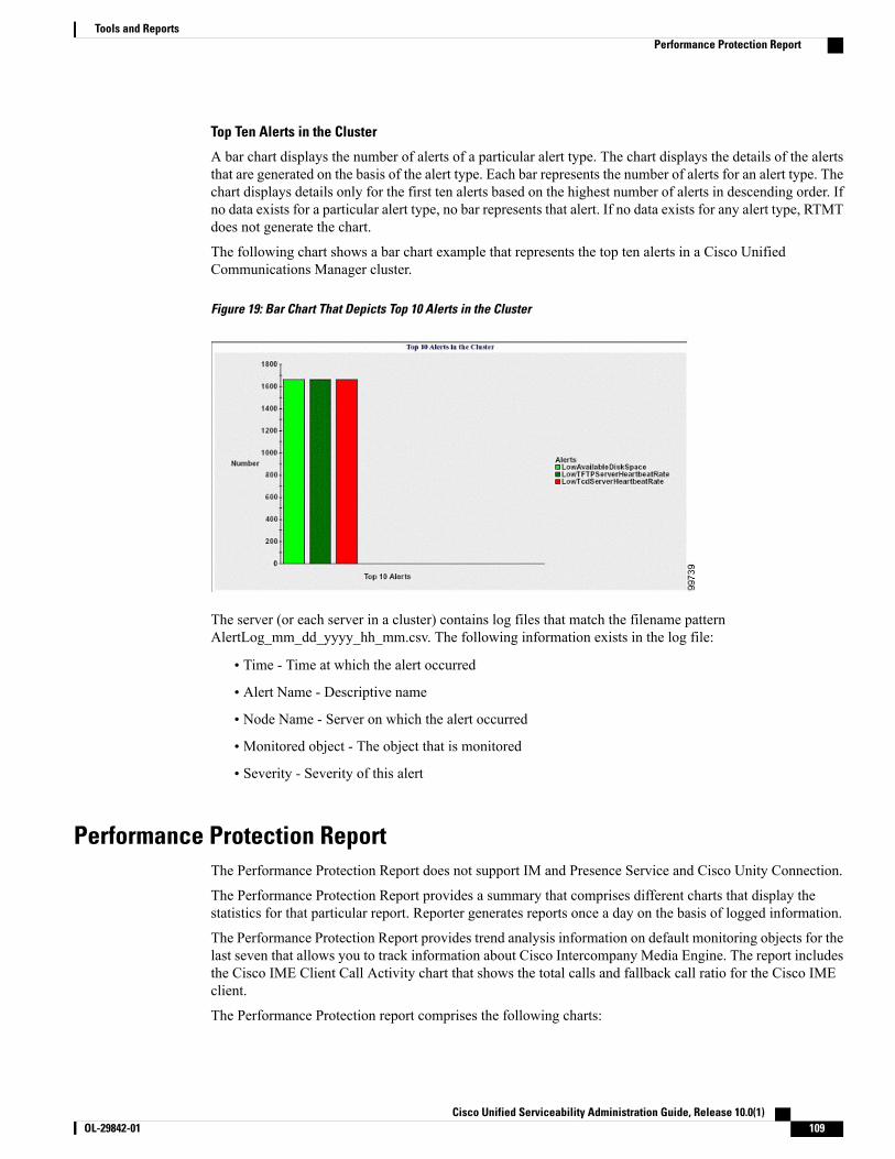
Top Ten Alerts in the Cluster
A bar chart displays the number of alerts of a particular alert type. The chart displays the details of the alertsthat are generated on the basis of the alert type. Each bar represents the number of alerts for an alert type. Thechart displays details only for the first ten alerts based on the highest number of alerts in descending order. Ifno data exists for a particular alert type, no bar represents that alert. If no data exists for any alert type, RTMTdoes not generate the chart.
The following chart shows a bar chart example that represents the top ten alerts in a Cisco UnifiedCommunications Manager cluster.
Figure 19: Bar Chart That Depicts Top 10 Alerts in the Cluster
The server (or each server in a cluster) contains log files that match the filename patternAlertLog_mm_dd_yyyy_hh_mm.csv. The following information exists in the log file:
• Time - Time at which the alert occurred
• Alert Name - Descriptive name
• Node Name - Server on which the alert occurred
• Monitored object - The object that is monitored
• Severity - Severity of this alert
Performance Protection ReportThe Performance Protection Report does not support IM and Presence Service and Cisco Unity Connection.
The Performance Protection Report provides a summary that comprises different charts that display thestatistics for that particular report. Reporter generates reports once a day on the basis of logged information.
The Performance Protection Report provides trend analysis information on default monitoring objects for thelast seven that allows you to track information about Cisco Intercompany Media Engine. The report includesthe Cisco IME Client Call Activity chart that shows the total calls and fallback call ratio for the Cisco IMEclient.
The Performance Protection report comprises the following charts:
Cisco Unified Serviceability Administration Guide, Release 10.0(1) OL-29842-01 109
Tools and ReportsPerformance Protection Report
• Cisco Unified Communications Manager Call Activity
• Number of registered phones and MGCP gateways
• System Resource Utilization
• Device and Dial Plan Quantities
Cisco Unified Communications Manager Call Activity
A line chart displays the hourly rate of increase or decrease for number of calls that were attempted and callsthat were completed as the number of active calls. For a Cisco Unified Communications Manager clusterconfiguration, the data is charted for each server in the cluster. The chart comprises three lines, one for thenumber of calls that were attempted, one for the calls that were completed, and one for the active calls. If nodata exists for call activity, Reporter does not generate the chart.
Number of registered phones and MGCP gateways
A line chart displays the number of registered phones and MGCP gateways. For a Cisco UnifiedCommunications Manager cluster configuration, the chart displays the data for each server in the cluster.Thechart comprises two lines, one for the number of registered phones and another for the number of MGCPgateways. If no data exists for phones or MGCP gateways, Reporter does not generate the chart.
System Resource Utilization
A line chart displays the CPU load percentage and the percentage of memory that is used (in bytes) for theserver (or for the whole cluster in a Cisco Unified CommunicationsManager cluster configuration). The chartcomprises two lines, one for the CPU load and one for the memory usage. In a Cisco Unified CommunicationsManager cluster, each line represents the cluster value, which is the average of the values for all the serversin the cluster (for which data is available). If no data exists for phones or MGCP gateways, Reporter does notgenerate the chart.
Device and Dial Plan Quantities
Two tables display information from the Cisco Unified CommunicationsManager database about the numbersof devices and number of dial plan components. The device table shows the number of IP phones, Cisco UnityConnection ports, H.323 clients, H.323 gateways, MGCP gateways, MOH resources, and MTP resources.The dial plan table shows the number of directory numbers and lines, route patterns, and translation patterns.
Set up serviceability reports archive overviewThe following steps provide information for configuring the serviceability report archive feature.
Procedure
Step 1 Activate the Cisco Serviceability Reporter service.Step 2 Configure the Cisco Serviceability Reporter service parameters.Step 3 View the reports that the Cisco Serviceability Reporter service generates.
Cisco Unified Serviceability Administration Guide, Release 10.0(1)110 OL-29842-01
Tools and ReportsSet up serviceability reports archive overview

Related Topics
Activate feature services, on page 89Serviceability Reporter service parameters, on page 94
Set up Serviceability Reports ArchiveThe Cisco Serviceability Reporter service generates daily reports in Cisco Unified Serviceability. Each reportprovides a summary that comprises different charts that display the statistics for that particular report. Reportergenerates reports once a day on the basis of logged information.
This section describes how to use the Serviceability Reports Archive window.
Before You Begin
Activate the Cisco Serviceability Reporter service, which is CPU intensive. After you activate the service,report generation may take up to 24 hours.
Cisco Unified Communications Manager only: Cisco recommends that you activate the service on anon-call-processing server.
Procedure
Step 1 Choose Tools > Serviceability Reports Archive.The Serviceability Reports Archive window displays the month and year for which the reports are available.
Step 2 From the Month-Year pane, choose the month and year for which you want to display reports.A list of days that correspond to the month displays.
Step 3 To view reports, click the link that corresponds to the day for which reports were generated.The report files for the day that you chose display.
Step 4 To view a particular PDF report, click the link of the report that you want to view.If you browsed into Cisco Unified Serviceability by using the node name, you must log in to CiscoUnified Serviceability before you can view the report.
If your network uses Network Address Translation (NAT) and you are trying to access serviceabilityreports inside the NAT, enter the IP address for the private network that is associated with the NATin the browser URL. If you are trying to access the reports outside the NAT, enter the public IP address,and NAT will accordingly translate/map to the private IP address.
To view PDF reports, you must install Acrobat Reader on your machine. To download Acrobat Reader,click the link at the bottom of the Serviceability Reports Archive window.
Tip
A window opens and displays the PDF file of the report that you chose.
Cisco Unified Serviceability Administration Guide, Release 10.0(1) OL-29842-01 111
Tools and ReportsSet up Serviceability Reports Archive

Access to Serviceability Reports Archive
Activate Serviceability Reports Archive
Procedure
Step 1 Select Tools > Service Activation.Step 2 Select the required server from the Server list box, and then select Go.Step 3 Navigate to the Performance and Monitoring services pane.Step 4 Check the Cisco Serviceability Reporter service checkbox, and then select Save.Step 5 Select Tools > Control Center - Feature Services.Step 6 Select the required server from the Server list box, and then select Go.Step 7 Navigate to the Performance and Monitoring services pane and locate the Cisco Serviceability Reporter.Step 8 Verify that the status of the Cisco Serviceability Reporter is Started and Activated. If the Cisco Serviceability
Reporter is not running, select the Cisco Serviceability Reporter and select Start.
What to Do Next
If you opened Cisco Unified IM and Presence Serviceability by entering the server name in the browser, youmust sign in to Cisco Unified IM and Presence Serviceability before you can view the report.
The Cisco Unified IM and Presence Serviceability service generates reports only on the first node, even ifyou turn on the service on other nodes.
Access Serviceability Reports Archive
Before You Begin
Activate the Cisco Serviceability Reporter service. After you activate the service, report generation may takeup to 24 hours.
Procedure
Step 1 Select Tools > Serviceability Reports Archive.Step 2 Select the month and year for which you want to display reports in theMonth-Year section.Step 3 Select the link that corresponds to the day for which reports were generated to view the required report.Step 4 Select the link of the report that you want to view to view a particular PDF report.
The section in the Trace Filter Settings area that relates to devices is not relevant to IM and Presence.
If you opened Cisco Unified IM and Presence Serviceability by entering the server name in the browser,you must sign in to Cisco Unified IM and Presence Serviceability before you can view the report.
Tip
Cisco Unified Serviceability Administration Guide, Release 10.0(1)112 OL-29842-01
Tools and ReportsAccess to Serviceability Reports Archive

CDR Repository ManagerThis section does not apply to IM and Presence Service.
Use the CDR Management Configuration window to set the amount of disk space to allocate to call detailrecord (CDR) and call management record (CMR) files, configure the number of days to preserve files beforedeletion, and configure up to three billing application server destinations for CDRs. The CDR RepositoryManager service repeatedly attempts to deliver CDR and CMR files to the billing servers that you configurein the CDR Management Configuration window until it delivers the files successfully, until you change ordelete the billing application server on the CDR Management Configuration window, or until the files falloutside the preservation window and are deleted.
To access the Enterprise Parameters Configuration window, open Cisco Unified CommunicationsManagerAdministration and choose System > Enterprise Parameters. The CDR File Time Interval parameterspecifies the time interval for collecting CDR data. For example, if this value is set to 1, each file willcontain 1 minute of CDR data (CDRs and CMRs, if enabled). The external billing server and CAR databasewill not receive the data in each file until the interval has expired, so consider how quickly you want accessto the CDR data when you decide what interval to set for this parameter. For example, setting this parameterto 60 means that each file will contain 60 minutes worth of data, but that data will not be available untilthe 60-minute period has elapsed, and the records are written to the CAR database. and the CDR files aresent to the configured billing servers. The default value equals 1. The minimum value specifies 1, and themaximum value specifies 1440. The unit of measure for this required field represents a minute.
Note
Both the CDR Agent and the CDR Repository Manager process files with an interval that is independent ofthe CDRFile Time Interval. The CDRRepositoryManager sends all existing CDR files to the billing applicationservers, sleeps for 6 seconds before checking the new files to send, and continues that 6-second interval. Ifthe destination (the external billing application servers) does not respond, the system attempts the processagain by using a doubled length of the sleep interval (12 seconds). Each delivery failure results in double thesleep time (6, 12, 24, 48,and so on, seconds) until 2 minutes occurs, then stays at 2-minute intervals untilsuccessful delivery occurs. After successful delivery, the 6-second interval automatically resumes.
Users cannot configure the 6-second processing time, with the sleep time interval doubling in case of failure.Users can configure only the CDR File Time Interval enterprise parameter. No alert gets sent after the firstfile delivery failure. By default, the system generates the CDRFileDeliveryFailed alert after the second deliveryfailure of the Cisco CDR Repository Manager service to deliver files to any billing application server. Youcan configure the alert to send you an e-mail or to page you. For information on configuring alerts, see the“Working with Alerts” chapter in the Cisco Unified Real-Time Monitoring Tool Administration Guide.
The system generates the CDRFileDeliveryFailureContinues syslog alarm upon subsequent failures to deliverthe files to the billing application servers.
The CDR Agent behaves in almost the same manner. First, it sends all the existing CDR files to the publisher.If no additional files to send exist, the CDR Agent sleeps for 6 seconds before checking for new files. Eachdelivery failure results in the immediate change of the sleep interval to 1 minute, then says at 1-minute intervalsuntil successful delivery. After the first successful delivery of files, the 6-second interval resumes.
The system sends no alert after the first file delivery failure by the CDRAgent. By default, the system generatesthe CDRAgentSendFileFailed alert after the second delivery failure of the CDR Agent. You can configurethe alert to send you an email or to page you. For information on configuring alerts, see the “Working withAlerts” chapter in the Cisco Unified Real-Time Monitoring Tool Administration Guide
Cisco Unified Serviceability Administration Guide, Release 10.0(1) OL-29842-01 113
Tools and ReportsCDR Repository Manager

The system generates the CDRAgentSendFileFailedContinues syslog alarm upon subsequent failures to deliverthe files.
If you need to start or restart the file transfer timer, you can restart the Cisco CDR Repository Manager orCDR Agent process by going to the Cisco Unified Serviceability window and selecting Tools > ControlCenter > Network Services.
When you enable the file deletion based on high water mark parameter, the CDR repository manager servicemonitors the amount of disk space that CDR and CMR files use. If disk usage exceeds the high water markthat you configure, the system purges the CDR and CMR files that have been successfully delivered to alldestinations and loaded into the CAR database (if CAR is activated) until the disk space reaches the low watermark or the system deletes all successfully delivered files. If disk usage still exceeds the high water mark afterthe system deletes all successfully delivered files, it does not delete any more files, unless the disk usage stillexceeds the disk allocation that you configure. If the disk usage still exceeds the disk allocation that youconfigure, the system purges files beginning with the oldest, regardless of whether the files fall within thepreservation window or have been successfully delivered, until the disk usage falls below the high water mark.
Regardless of whether you enable the deletion of files based on the high water mark parameter, if diskusage exceeds the disk allocation that you configure, the CDR repository manager service deletes CDRand CMR files, beginning with the oldest files, until disk utilization falls below the high water mark.
Note
The Cisco Log Partition Monitoring Tool service monitors the disk usage of CDR and CMR flat files thathave not been delivered to the CDR repository manager.
Cisco Unified Communications Manager only: If the disk usage of the log partition on a server exceeds theconfigured limit and the service has deleted all other log and trace files, the log partition monitor servicedeletes CDR/CMR files on the subsequent nodes that have not been delivered to the CDR repository manager.
For more information about log partition monitoring, see the Cisco Unified Real-Time Monitoring ToolAdministration Guide.
Set up general parametersTo set disk utilization and file preservation parameters for CDRs, perform the following procedure.
Procedure
Step 1 Choose Tools > CDRManagement.The CDR Management window displays.
Step 2 Click the CDR Manager general parameter value that you want to change.Step 3 Enter the appropriate CDR Repository Manager general parameter settings.Step 4 Click Update.
At any time, you can click Set Default to specify the default values. After you set the defaults, clickUpdate to save the default values.
Tip
Related Topics
General parameter settings, on page 115
Cisco Unified Serviceability Administration Guide, Release 10.0(1)114 OL-29842-01
Tools and ReportsSet up general parameters

General parameter settingsThe following table describes the available settings in the General Parameters section of the CDRManagementConfiguration window.
Table 47: CDR Repository Manager General Parameter Settings
DescriptionField
Choose the number of megabytes that you want to allocate to CDR and CMR flat filestorage.
The default disk allocation and range vary depending on the size of the server harddrive.
The maximum CAR database size equals 6 GB for a Cisco UnifiedCommunications Manager server.
If disk usage exceeds the allocated maximum disk space for CDR files, thesystem generates the CDRMaximumDiskSpaceExceeded alert and deletesall successfully processed files (those delivered to billing servers and loadedto CAR). If disk usage still exceeds the allocated disk space, the system deletesundelivered files and files within the preservation duration, starting with theoldest, until disk utilization falls below the high water mark.
If you have a large system and do not allocate enough disk space, the systemmay delete the CDR and CMR files before the CAR Scheduler loads the filesinto the CAR database. For example, if you configure the CAR Scheduler torun once a day and you set the disk allocation to a value that is not largeenough to hold the CDR and CMR files that are generated in a day, the systemwill delete the files before they are loaded into the CAR database.
Note
Disk Allocation(MB)
This field specifies the maximum percentage of the allocated disk space for CDR andCMR files. For example, if you choose 2000megabytes from the Disk Allocation fieldand 80% from the High Water Mark (%) field, the high water mark equals 1600megabytes. In addition to the high water mark percentage, the number of CDRs in theCAR database cannot exceed twomillion records for a Cisco Unified CommunicationsManager server.
When the disk usage exceeds the percentage that you specify, or the total number ofCDRs is exceeded, and the Disable CDR/CMR Files Deletion Based on HWM checkbox is unchecked, the system automatically purges all successfully processed CDRand CMR files (those delivered to billing servers and loaded to CAR) beginning withthe oldest files to reduce disk usage to the amount that you specify in the Low WaterMark (%) drop-down list box.
If the disk usage still exceeds the low water mark or high water mark, the system doesnot delete any undelivered or unloaded files, unless the disk usage exceeds the diskallocation.
If you check the Disable CDR/CMR Files Deletion Based on HWM check box, thesystem does not delete CDRs and CMRs based on the percentage that you specify inthis field.
If CDR disk space exceeds the high water mark, the system generates theCDRHWMExceeded alert.
Note
High Water Mark(%)
Cisco Unified Serviceability Administration Guide, Release 10.0(1) OL-29842-01 115
Tools and ReportsGeneral parameter settings

DescriptionField
This field specifies the percentage of disk space that is allocated to CDR and CMRfiles that is always available for use. For example, if you choose 2000 megabytes fromthe Disk Allocation field and 40% from the LowWater Mark (%) field, the low watermark equals 800 megabytes.
Low Water Mark(%)
Choose the number of days that you want to retain CDR and CMR files. The CDRRepository Manager deletes files that fall outside the preservation window.
If you continuously receive the CDRMaximumDiskSpaceExceeded alarm,you either must increase the disk allocation or lower the number ofpreservation days.
Note
CDR / CMR FilesPreservationDuration (Days)
Regardless of whether you enable the deletion of files based on the high-watermark parameter, if disk usage exceeds the disk allocation that you configure,the maximum database size, or the maximum number of records for yourinstallation, the CDR repository manager service deletes CDR and CMR files,beginning with the oldest files, until disk utilization falls below the high watermark.
Note
If you do not want to delete CDRs and CMRs even if disk usage exceeds the percentagethat you specify in the High Water Mark (%) field, check this check box. By default,this check box remains unchecked, so the system deletes CDRs and CMRs if diskusage exceeds the high water mark.
Disable CDR/CMRFiles DeletionBased on HWM
This field lists the hostname of the CDR repository manager server.CDR RepositoryManager HostName
This field lists the IP address of the CDR repository manager server.CDR RepositoryManager HostAddress
Set up application billing serversUse the following procedure to configure application billing servers to which you want to send CDRs. Youcan configure up to three billing servers.
Procedure
Step 1 Choose Tools > CDRManagement Configuration.The CDR Management Configuration window displays.
Step 2 Perform one of the following tasks:
• To add a new application billing server, click the Add New button.
• To update an existing application billing server, click the server hostname/IP address.
Cisco Unified Serviceability Administration Guide, Release 10.0(1)116 OL-29842-01
Tools and ReportsSet up application billing servers

Step 3 Enter the application billing server parameter settings.Step 4 Click Add or Update.
Related Topics
Application billing server parameter settings, on page 117
Application billing server parameter settingsThe following table describes the available settings in the Billing Application Server Parameters section ofthe CDR Management Configuration window.
Table 48: Application Billing Server Parameter Settings
DescriptionField
Enter the hostname or IP address of the application billing serverto which you want to send CDRs.
If you change the value in this field, a prompt asks whether youwant to send the undelivered files to the new destination.
Perform one of the following tasks:
• To deliver the files to the new server, click Yes.
• To change the server hostname/IP address without sendingundelivered files, clickNo. The CDRManagement servicemarks the CDR and CMR files as delivered.
Host Name/IP Address
Enter the username of the application billing server.User Name
Choose the protocol, either FTP or SFTP, that you want to useto send the CDR files to the configured billing servers.
Protocol
Enter the directory path on the application billing server to whichyou want to send the CDRs. You should end the path that youspecify with a “/” or “\”, depending on the operating system thatis running on the application billing server.
Make sure the FTP user has write permission to thedirectory.
Note
Directory Path
Enter the password that is used to access the application billingserver.
Password
Cisco Unified Serviceability Administration Guide, Release 10.0(1) OL-29842-01 117
Tools and ReportsApplication billing server parameter settings

DescriptionField
When you check the Resend on Failure box, this option informsCDRM to send outdated CDR and CMR files to the billing serverafter the FTP or SFTP connection is restored. When the box ischecked, the Resend on Failure flag is set to True. When the boxis not checked, the Resend on Failure flag is set to False.
There are several different scenarios that can occur. When thebilling server Resend on Failure flag is set to True, all CDR filesget moved to the billing server. When the Resend On Failureflag is set to False, CDR files that get generated during shutdownof the billing server get moved to the processed folder, but donot get moved to the billing server. When the Resend on Failureflag gets set to True at the beginning, and then gets changedseveral times, the result is that the CDR files get moved to thebilling server whenever the Resend on Failure box gets checked.
Resend on Failure
Click on the Reset button to generate new keys and reset theconnection to the SFTP server.
Generate New Key
Delete application billing serversUse the following procedure to delete an application billing server.
Procedure
Step 1 Choose Tools > CDRManagement.The CDR Management Configuration window displays.
Step 2 Check the check box next to the application billing server that you want to delete and click Delete Selected.A message displays that indicates that if you delete this server, any CDR or CMR files that have not been sentto this server will not be delivered to this server and will be treated as successfully delivered files.
When you delete a server, the system does not generate the CDRFileDeliveryFailed alert for the filesthat are not sent to that server.
Tip
Step 3 To complete the deletion, click OK.
Audit logsWith audit logging, configuration changes to the system get logged in separate log files for auditing.
Cisco Unified Serviceability Administration Guide, Release 10.0(1)118 OL-29842-01
Tools and ReportsDelete application billing servers

Audit loggingWith audit logging, configuration changes to the system get logged in separate log files for auditing. TheCisco Audit Event Service, which displays under Control Center - Network Services in the serviceability GUI,monitors and logs any configuration changes to the system that are made by a user or as a result of the useraction.
You access the Audit Log Configuration window in the serviceability GUI to configure the settings for theaudit logs.
Audit logging contains the following parts:
• Audit logging framework - The framework comprises an API that uses an alarm library to write auditevents into audit logs. An alarm catalog that is defined as GenericAlarmCatalog.xml applies for thesealarms. Different system components provide their own logging.
The following example displays an API that a Cisco Unified Communications Manager component canuse to send an alarm:
User ID: CCMAdministratorClient IP Address: 172.19.240.207Severity: 3EventType: ServiceStatusUpdatedResourceAccessed: CCMServiceEventStatus: SuccessfulDescription: CallManager Service status is stopped
• Audit event logging - An audit event represents any event that is required to be logged. The followingexample displays a sample audit event:
CCM_TOMCAT-GENERIC-3-AuditEventGenerated: Audit Event GeneratedUserID:CCMAdministrator Client IP Address:172.19.240.207 Severity:3EventType:ServiceStatusUpdated ResourceAccessed: CCMServiceEventStatus:Successful Description: Call Manager Service status isstopped App ID:Cisco Tomcat Cluster ID:StandAloneCluster NodeID:sa-cm1-3
Be aware that audit event logging is centralized and enabled by default. An alarm monitor called SyslogAudit writes the logs. By default, the logs are configured to rotate. If the AuditLogAlarmMonitor cannotwrite an audit event, the AuditLogAlarmMonitor logs this failure as a critical error in the syslog file. TheAlert Manager reports this error as part of a SeverityMatchFound alert. The actual operation continueseven if the event logging fails. All audit logs get collected, viewed, and deleted from Trace and Log Centralin the Cisco Unified Real-Time Monitoring Tool.
Tip
Cisco Unified Serviceability events logging
Cisco Unified Serviceability logs the following events:
• Activation, deactivation, start, or stop of a service.
• Changes in trace configurations and alarm configurations.
• Changes in SNMP configurations.
Cisco Unified Serviceability Administration Guide, Release 10.0(1) OL-29842-01 119
Tools and ReportsAudit logging

• Changes in CDR management. (Cisco Unified Communications Manager only)
• Review of any report in the Serviceability Reports Archive. This log gets viewed on the reporter node.(Cisco Unified Communications Manager only)
Cisco Unified Real-Time Monitoring Tool events logging
Cisco Unified Real-Time Monitoring Tool logs the following events with an audit event alarm:
• Alert configuration
• Alert suspension
• E-mail configuration
• Set node alert status
• Alert addition
• Add alert action
• Clear alert
• Enable alert
• Remove alert action
• Remove alert
Cisco Unified Communications Manager CDR Analysis and Reporting events logging
Cisco Unified Communications Manager CDR Analysis and Reporting (CAR) creates audit logs for theseevents:
• Loader scheduling
• Daily, weekly, and monthly reports scheduling
• Mail parameters configuration
• Dial plan configuration
• Gateway configuration
• System preferences configuration
• Autopurge configuration
• Rating engine configurations for duration, time of day, and voice quality
• QoS configurations
• Automatic generation/alert of pregenerated reports configurations.
• Notification limits configuration
Cisco Unified Communications Manager Administration events logging
The following events get logged for various components of Cisco Unified Communications ManagerAdministration:
Cisco Unified Serviceability Administration Guide, Release 10.0(1)120 OL-29842-01
Tools and ReportsAudit logging

• User logging (user logins and user logouts)
• User role membership updates (user added, user deleted, user role updated)
• Role updates (new roles added, deleted, or updated)
• Device updates (phones and gateways)
• Server configuration updates (changes to alarm or trace configurations, service parameters, enterpriseparameters, IP addresses, hostnames, Ethernet settings, and Cisco Unified Communications Managerserver additions or deletions)
Cisco Unified Communications Manager Administration events logging
The following events get logged for various components of Cisco Unified Communications ManagerAdministration:
• User logging (user logins and user logouts)
• User role membership updates (user added, user deleted, user role updated)
• Role updates (new roles added, deleted, or updated)
• Device updates (phones and gateways)
• Server configuration updates (changes to alarm or trace configurations, service parameters, enterpriseparameters, IP addresses, hostnames, Ethernet settings, and Cisco Unified Communications Managerserver additions or deletions)
Cisco Unified Communications Manager User Options logging
User logging (user login and user logout) events are logged for Cisco Unified CommunicationsManager UserOptions.
Command-Line Interface events logging
All commands issued via the command-line interface are logged (for both Cisco Unified CommunicationsManager and Cisco Unity Connection).
Cisco Unity Connection Administration events logging
Cisco Unity Connection Administration logs the following events:
• User logging (user logins and user logouts)
• All configuration changes, including but not limited to users, contacts, call management objects,networking, system settings, and telephony
• Task management (enabling or disabling a task)
• Bulk Administration Tool (bulk creates, bulk deletes)
• Custom Keypad Map (map updates)
Cisco Personal Communications Assistant (Cisco PCA)
The Cisco Personal Communications Assistant client logs the following events:
Cisco Unified Serviceability Administration Guide, Release 10.0(1) OL-29842-01 121
Tools and ReportsAudit logging

• User logging (user logins and user logouts)
• All configuration changes made via the Messaging Assistant
Cisco Unity Connection Serviceability events logging
Cisco Unity Connection Serviceability logs the following events:
• User logging (user logins and user logouts).
• All configuration changes.
• Activating, deactivating, starting or stopping services.
Cisco Unity Connection Clients that Use the Representational State Transfer APIs events logging
Cisco Unity Connection clients that use the Representational State Transfer (REST) APIs log the followingevents:
• User logging (user API authentication).
• API calls that utilize Cisco Unity Connection Provisioning Interface.
Cisco Unified IM and Presence Serviceability events logging
Cisco Unified IM and Presence Serviceability logs the following events:
• Activation, deactivation, start, or stop of a service
• Changes in trace configurations and alarm configurations
• Changes in SNMP configurations
• Review of any report in the Serviceability Reports Archive (this log gets viewed on the reporter node)
Cisco Unified IM and Presence Real-Time Monitoring Tool events logging
Cisco Unified IM and Presence Real-Time Monitoring Tool logs the following events with an audit eventalarm:
• Alert configuration
• Alert suspension
• E-mail configuration
• Set node alert status
• Alert addition
• Add alert action
• Clear alert
• Enable alert
• Remove alert action
• Remove alert
Cisco Unified Serviceability Administration Guide, Release 10.0(1)122 OL-29842-01
Tools and ReportsAudit logging

Cisco Unified Communications Manager IM and Presence Administration events logging
The following events get logged for various components of Cisco Unified Communications Manager IM andPresence Administration:
• Administrator logging (logins and logouts on IM and Presence interfaces such as Administration, OSAdministration, Disaster Recovery System, and Reporting)
• User role membership updates (user added, user deleted, user role updated)
• Role updates (new roles added, deleted, or updated)
• Device updates (phones and gateways)
• Server configuration updates (changes to alarm or trace configurations, service parameters, enterpriseparameters, IP addresses, hostnames, Ethernet settings, and IM and Presence server additions or deletions)
IM and Presence Application events logging
The following events get logged by the various components of the IM and Presence Application:
• End user logging on IM clients (user logins, user logouts, and failed login attempts)
• User entry to and exit from IM Chat Rooms
• Creation and destruction of IM Chat Rooms
Command Line Interface events logging
All commands issued through the command line interface are logged.
System audit logsSystem audit logs track activities such as the creation, modification, or deletion of Linux OS users, logtampering, and any changes to file or directory permissions. This type of audit log is disabled by default dueto the high volume of data gathered. To enable this function, you must manually enable utils auditd using theCLI. After you have enabled the system audit log feature, you can collect, view, download, or delete selectedlogs through Trace & Log Central from the Real-Time Monitoring Tool. System audit logs take on the formatof vos-audit.log.
For information about how to enable this feature, see the Command Line Interface Reference Guide for CiscoUnified Communications Solutions. For information about how to access collected logs from the Real-TimeMonitoring Tool, see the Cisco Unified Real-Time Monitoring Tool Administration Guide .
Application audit logsThe Application Audit logs monitor and record any configuration changes to the system that were made bya user or as a result of the user action.
Database audit logsDatabase Audit Logs track all activities associated with access to the Informix Database, such as logins.
Cisco Unified Serviceability Administration Guide, Release 10.0(1) OL-29842-01 123
Tools and ReportsAudit logging
Set up audit logTo configure the audit log using the serviceability GUI, perform the following procedure.
The Application Audit Logs (Linux auditd) can be enabled or disabled only through the CLI. Other thanthe collection of vos-audit.log through the Real-Time Monitoring Tool, you can not change any settingsfor this type of audit log.
Note
Procedure
Step 1 Select Tools > Audit Log Configuration.The Audit Log Configuration window displays.
Step 2 Configure the audit log settings.Step 3 Click Save.
At any time, you can click Set to Default to specify the default values. After you set the defaults, clickSave to save the default values.
Tip
Related Topics
Audit log configuration settings, on page 124
Audit log configuration settings
Before You Begin
Be aware that only a user with an audit role can change the audit log settings. By default, for Cisco UnifiedCommunications Manager, the CCMAdministrator possesses the audit role after fresh installs and upgrades.The CCMAdministrator can assign any user that has auditing privileges to the Standard Audit Users groupin the User Group Configuration window in Cisco Unified Communications Manager Administration. If youwant to do so, you can then remove CCMAdministrator from the Standard Audit Users group.
For IM and Presence Service, the administrator possesses the audit role after fresh installs and upgrades, andcan assign any user that has auditing privileges to the Standard Audit Users group.
For Cisco Unity Connection, the application administration account that was created during installation hasthe Audit Administrator role and can assign other administrative users to the role. You can also remove theAudit Administrator role from this account.
The Standard Audit Log Configuration role is to provide the ability to delete audit logs and to read/updateaccess to Cisco Unified Real-Time Monitoring Tool, IM and Presence Real-Time Monitoring Tool, TraceCollection Tool, RTMT Alert Configuration, Control Center - Network Services in the serviceability GUI,RTMT Profile Saving, Audit Configuration in the serviceability GUI, and a resource that is called AuditTraces.
The Standard Audit Log Configuration role is to provide the ability to delete audit logs and to read/updateaccess to Cisco Unified Real-Time Monitoring Tool, Trace Collection Tool, RTMT Alert Configuration,
Cisco Unified Serviceability Administration Guide, Release 10.0(1)124 OL-29842-01
Tools and ReportsSet up audit log

Control Center - Network Services in Cisco Unified Serviceability, RTMT Profile Saving, Audit Configurationin Cisco Unified Serviceability, and a resource that is called Audit Traces.
The Audit Administrator role in Cisco Unity Connection provides the ability to view, download and deleteaudit logs in Cisco Unified Real-Time Monitoring Tool.
For information on roles, users, and user groups in Cisco Unified CommunicationsManager, refer to theCiscoUnified Communications Manager Administration Guide.
For information on roles and users in Cisco Unity Connection, refer to the User Moves, Adds, and ChangesGuide for Cisco Unity Connection.
For information on roles, users, and user groups in IM and Presence, refer to the Deployment Guide for IMand Presence Service on Cisco Unified Communications Manager.
The following table describes the settings that you can configure in the Audit Log Configuration window inCisco Unified Serviceability.
Table 49: Audit Log Configuration Settings
DescriptionField
Select Server
Choose the server (node) where you want to configure audit logs; then, clickGo.Server
If you want to apply the audit log configuration to all nodes in the cluster, checkthe Apply to all Nodes box.
Apply to All Nodes
Application Audit Log Settings
When you check this check box, an audit log gets created for the applicationaudit log.
For Cisco Unified Communications Manager, the application audit log supportsconfiguration updates for Cisco Unified Communications Manager GUIs, suchas Cisco Unified Communications Manager Administration, Cisco UnifiedReal-Time Monitoring Tool, Cisco Unified Communications Manager CDRAnalysis and Reporting, and Cisco Unified Serviceability.
For IM and Presence Service, the application audit log supports configurationupdates for IM and Presence GUIs, such as Cisco Unified CommunicationsManager IM and Presence Administration, Cisco Unified IM and PresenceReal-Time Monitoring Tool, and Cisco Unified IM and Presence Serviceability.
For Cisco Unity Connection, the application audit log supports configurationupdates for Cisco Unity Connection graphical user interfaces, including CiscoUnity Connection Administration, Cisco Unity Connection Serviceability, CiscoPersonal Communications Assistant, and clients that use the Connection RESTAPIs.
This setting displays as enabled by default.
The Network Service Audit Event Service must berunning.
Note
Enable Audit Log
Cisco Unified Serviceability Administration Guide, Release 10.0(1) OL-29842-01 125
Tools and ReportsAudit log configuration settings

DescriptionField
The Log PartitionMonitor (LPM) looks at the Enable Purging option to determinewhether it needs to purge audit logs.When you check this check box, LPM purgesall the audit log files in RTMT whenever the common partition disk usage goesabove the high water mark; however, you can disable purging by unchecking thecheck box.
If purging is disabled, the number of audit logs continues to increase until thedisk is full. This action could cause a disruption of the system. A message thatdescribes the risk of disabling the purge displays when you uncheck the EnablePurging check box. Be aware that this option is available for audit logs in anactive partition. If the audit logs reside in an inactive partition, the audit logs getpurged when the disk usage goes above the high water mark.
You can access the audit logs by choosing Trace and Log Central > AuditLogs in RTMT.
The Network Service Cisco Log Partitions Monitoring tool must berunning.
Note
Enable Purging
The system reads this option to determine whether it needs to rotate the audit logfiles or it needs to continue to create new files. The maximum number of filescannot exceed 5000.When the Enable Rotation check box is checked, the systembegins to overwrite the oldest audit log files after the maximum number of filesgets reached.
When log rotation is disabled (unchecked), audit log ignores theMaximumNo. of Files setting.
Tip
Enable Log Rotation
Enter the name or IP address of the remote syslog server that you want to use toaccept syslog messages. If server name is not specified, Cisco Unified IM andPresence Serviceability does not send the syslog messages. Do not specify aCisco Unified Communications Manager node as the destination because theCisco Unified Communications Manager node does not accept syslog messagesfrom another server.
This applies to IM and Presence Service only.
Server Name
Select the desired syslog messages severity for the remote syslog server. All thesyslog messages with selected or higher severity level are sent to the remotesyslog.
This applies to IM and Presence Service only.
Remote Syslog AuditEvent Level
Enter the maximum number of files that you want to include in the log. Thedefault setting specifies 250. The maximum number specifies 5000.
Maximum No. of Files
Enter the maximum file size for the audit log. The file size value must remainbetween 1 MB and 10 MB. You must specify a number between 1 and 10.
Maximum File Size
Database Audit Log Filter Settings
Cisco Unified Serviceability Administration Guide, Release 10.0(1)126 OL-29842-01
Tools and ReportsAudit log configuration settings
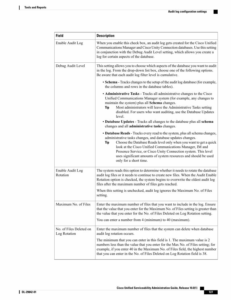
DescriptionField
When you enable this check box, an audit log gets created for the Cisco UnifiedCommunicationsManager and CiscoUnity Connection databases. Use this settingin conjunction with the Debug Audit Level setting, which allows you create alog for certain aspects of the database.
Enable Audit Log
This setting allows you to choose which aspects of the database you want to auditin the log. From the drop-down list box, choose one of the following options.Be aware that each audit log filter level is cumulative.
• Schema - Tracks changes to the setup of the audit log database (for example,the columns and rows in the database tables).
• Administrative Tasks - Tracks all administrative changes to the CiscoUnified Communications Manager system (for example, any changes tomaintain the system) plus all Schema changes.
Most administrators will leave the Administrative Tasks settingdisabled. For users who want auditing, use the Database Updateslevel.
Tip
• Database Updates - Tracks all changes to the database plus all schemachanges and all administrative tasks changes.
• Database Reads - Tracks every read to the system, plus all schema changes,administrative tasks changes, and database updates changes.
Choose the Database Reads level only when you want to get a quicklook at the Cisco Unified Communications Manager, IM andPresence Service, or Cisco Unity Connection system. This leveluses significant amounts of system resources and should be usedonly for a short time.
Tip
Debug Audit Level
The system reads this option to determine whether it needs to rotate the databaseaudit log files or it needs to continue to create new files. When the Audit EnableRotation option is checked, the system begins to overwrite the oldest audit logfiles after the maximum number of files gets reached.
When this setting is unchecked, audit log ignores the Maximum No. of Filessetting.
Enable Audit LogRotation
Enter the maximum number of files that you want to include in the log. Ensurethat the value that you enter for the Maximum No. of Files setting is greater thanthe value that you enter for the No. of Files Deleted on Log Rotation setting.
You can enter a number from 4 (minimum) to 40 (maximum).
Maximum No. of Files
Enter the maximum number of files that the system can delete when databaseaudit log rotation occurs.
The minimum that you can enter in this field is 1. The maximum value is 2numbers less than the value that you enter for the Max No. of Files setting; forexample, if you enter 40 in the Maximum No. of Files field, the highest numberthat you can enter in the No. of Files Deleted on Log Rotation field is 38.
No. of Files Deleted onLog Rotation
Cisco Unified Serviceability Administration Guide, Release 10.0(1) OL-29842-01 127
Tools and ReportsAudit log configuration settings

When enabled, database logging can generate large amounts of data in a short period, particularly if thedebug audit level is set to Database Updates or Database Reads. This can result in a significantperformance impact during heavy usage periods. In general, we recommend that you keep database loggingdisabled. If you do need to enable logging to track changes in the database, we recommend that you doso only for short periods of time, by using the Database Updates level. Similarly, administrative loggingdoes impact on the overall performance of the web user interface, especially when polling database entries(for example, pulling up 250 devices from the database).
Caution
LocationsThis section does not apply to IM and Presence Service.
This section explains the Locations feature (Tools > Locations) in Cisco Unified Serviceability. This featureenables an administrator to view details of the configured locations in an enterprise, understand the link andintralocation discrepancies, view effective path between the two locations, and identify disconnected groupsof locations.
Locations TopologyCisco Unified Serviceability Locations Topology provides details of configured locations in your enterprise.Location Topology refers to a modeled topology representing the flow of media in a network.
The following are some commonly used terms and their definitions:
Assertion
An assertion refers to the location and link bandwidth and weight values configured in a cluster. Assertedvalues may be replicated to another cluster.
Discrepancy
A discrepancy occurs if there is a difference in the location bandwidth values or link bandwidth and weightvalues asserted across various clusters.
Effective Path
An Effective Path is a sequence of intermediate locations connecting two end locations, with weight assignedto each link between each adjacent pair of locations. The Effective Path, as determined by the least cumulativeweight, is the only path used for bandwidth deductions between any two end locations.
View locations topologyCisco Unified Serviceability Locations Topology helps an administrator view the graphical locations topologyin a tabular format. The administrator can filter required location names using the Find filter. The locationstopology data includes the intralocation details and link details for a selected location.This section describes how to search and view location topology in Cisco Unified Serviceability.
Procedure
Step 1 In Cisco Unified Serviceability, choose Tools > Locations > Topology.
Cisco Unified Serviceability Administration Guide, Release 10.0(1)128 OL-29842-01
Tools and ReportsLocations

The Locations Topology window appears.
Step 2 From the Find Locations Where Location Name drop-down box, choose the filter criteria.Step 3 Enter the search string in the Find Locations Where Location Name field and then click Find.
The Find Locations Where Location Name field is notcasesensitive.
Note
The list of locations is displayed for the chosen filter criteria.
Step 4 In the list, click to expand any location to view its intralocation details and link details.The intralocation details include audio, video, and immersive bandwidth whereas the link details contain thedetails of the link connecting two locations such as its weight, audio, video and immersive bandwidth.
If the list of locations is long, it may run into multiple pages. To view another page, click the appropriatenavigation button at the bottom of the Locations Topology window or enter a page number in the Pagefield. To change the number of locations that display in the window, choose a different value from theRows Per Page drop-down box.
Tip
If a location is highlighted by a Caution symbol, this indicates a discrepancy. To view the details ofthis discrepancy, click View Assertion Details link.
Tip
Step 5 To view the assertion details of any location, clickView Assertion Details link at the bottom of the expandeddetails section.The Assertion Details window appears.
Step 6 To return to the Locations Topology window, click Close.To download the locations topology data in XML format, click Download Topology at the bottomof the Locations Topology window or Download Topology icon in the toolbar at the top.
Note
For more information about the topology data in XML format, see theCisco Unified CommunicationsManagerXML Developers Guide.
View assertion details
Use the serviceability GUI to view the following assertion details:
• Intralocation configuration assertions—Includes the intralocation assertion details such as Asserted byCluster, Audio, Video and Immersive bandwidth. Asserted by Cluster column lists the names of all theclusters that assert a particular location.
• Link assertions—Includes the assertion details of the link that connects two locations, such as Assertedby Cluster, Weight, Audio, Video, and Immersive bandwidth.
Procedure
Step 1 Select Tools > Locations > Locations Topology.Step 2 Click the View Assertion Details link in the Locations Topology window.
Cisco Unified Serviceability Administration Guide, Release 10.0(1) OL-29842-01 129
Tools and ReportsLocations Topology
Locations discrepancyThe Locations Discrepancy screen displays the conflicts in assertions for various locations configurations.
The following details are displayed:
• Link Configuration Discrepancy—Includes the discrepancy details of the link that connects two locations,such as Weight, Audio, Video and Immersive bandwidth.
• Intralocation Configuration Discrepancy—Includes intralocation discrepancy details such as Audio,Video, and Immersive bandwidth.
View locations discrepancyThis section describes how to view a location discrepancy in Cisco Unified Serviceability.
Procedure
Step 1 In Cisco Unified Serviceability, choose Tools > Locations > Discrepancy.The Location Discrepancy window appears.
Step 2 The list of link configuration discrepancies and intralocation configuration discrepancies is displayed.The Link Configuration Discrepancy section lists only those link names where discrepancy has beendetected. Link names are listed in the format <Location Name 1> <--> <Location Name 2>. TheIntralocation ConfigurationDiscrepancy section lists only those location nameswhere such discrepancyhas been detected. The elements in the list are sorted in lexical order.
Note
If no discrepancies are found, the following status message is displayed:
No discrepancies found
Step 3 In the list, click on a link name or location name to expand and view its configuration details as asserted bydifferent clusters, in a tabular view.The bottom row displays the effective values considered for audio, video, and immersive bandwidth poolsand weight (in the case of links). The values that do not match with the effective values are highlighted inred.
The Effective Value is the least of the values in a particular column. For example, the Effective Valueof audio bandwidth is the minimum value in the Audio Bandwidth column.
Note
Effective pathThe Cisco Unified Serviceability Effective Path screen provides details of the effective path that media takesfor audio, video, or immersive calls made between two locations provided by the administrator. This screendisplays the Available bandwidth and the Configured bandwidth across each link and intralocation in theeffective path. An administrator can use this report to determine bandwidth availability across a link andintra-location when there are bandwidth issues in making calls. Cisco Unified Serviceability Effective Pathcan also be used to troubleshoot bandwidth issues in making calls and find out where the bandwidth availabilityis low.
Cisco Unified Serviceability Administration Guide, Release 10.0(1)130 OL-29842-01
Tools and ReportsLocations discrepancy

The Cisco Unified Serviceability Effective Path screen displays the following details between two selectedlocations:
• Quick Path Overview—Displays the cumulative weight and the least of the configured and availableAudio, Video, and Immersive Bandwidth values across the effective path.
• Detailed Path View—Displays the weight and bandwidth values (Available and Configured) for Audio,Video, and Immersive calls for locations and links constituting the effective path, in a tabular viewordered from source location at top to the destination location at bottom.
The Available bandwidth values displayed in the report are the value at the time of viewing the EffectivePath. You can view the real-time values in the Cisco Unified Real-Time Monitoring Tool.
Note
View effective path
Procedure
Step 1 In Cisco Unified Serviceability, choose Tools > Locations > Effective Path.The Effective Path window appears.
Step 2 From the Location drop-down boxes, select any two locations between which effective path is required andthen click Find.Alternatively, start typing the location name in the input box to shortlist the matching location names and thenclick Find.
The effective path details, which include the Quick Path Overview and Detailed Path View sections, aredisplayed. If there is no path between the two selected locations, the following status message is displayed:
No path exists between <From_Location> and <To_Location>.
Disconnected groupsCisco Unified Serviceability Disconnected Groups screen enables an administrator to view and analyze anydisconnect between the locations that are part of the topology. It displays a list of disconnected groups oflocations, which helps an administrator understand which locations need to be connected.
The disconnect in the topology can occur when a link between two locations is not configured or a sharedlocation name is misspelled.
The Disconnected Groups screen displays and compares only disconnected groups of locations. Forinformation on connecting locations, see topics related to location configuration in Cisco UnifiedCommunications Manager Administration Guide.
Note
Cisco Unified Serviceability Administration Guide, Release 10.0(1) OL-29842-01 131
Tools and ReportsDisconnected groups
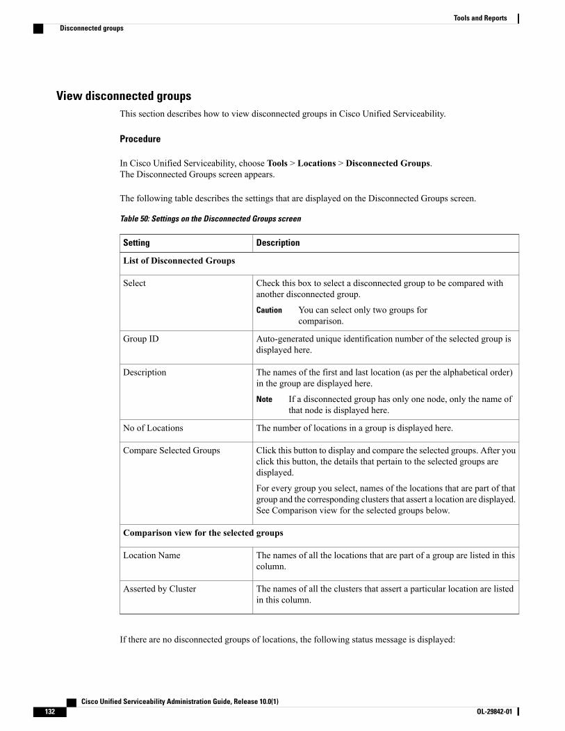
View disconnected groupsThis section describes how to view disconnected groups in Cisco Unified Serviceability.
Procedure
In Cisco Unified Serviceability, choose Tools > Locations > Disconnected Groups.The Disconnected Groups screen appears.
The following table describes the settings that are displayed on the Disconnected Groups screen.
Table 50: Settings on the Disconnected Groups screen
DescriptionSetting
List of Disconnected Groups
Check this box to select a disconnected group to be compared withanother disconnected group.
You can select only two groups forcomparison.
Caution
Select
Auto-generated unique identification number of the selected group isdisplayed here.
Group ID
The names of the first and last location (as per the alphabetical order)in the group are displayed here.
If a disconnected group has only one node, only the name ofthat node is displayed here.
Note
Description
The number of locations in a group is displayed here.No of Locations
Click this button to display and compare the selected groups. After youclick this button, the details that pertain to the selected groups aredisplayed.
For every group you select, names of the locations that are part of thatgroup and the corresponding clusters that assert a location are displayed.See Comparison view for the selected groups below.
Compare Selected Groups
Comparison view for the selected groups
The names of all the locations that are part of a group are listed in thiscolumn.
Location Name
The names of all the clusters that assert a particular location are listedin this column.
Asserted by Cluster
If there are no disconnected groups of locations, the following status message is displayed:
Cisco Unified Serviceability Administration Guide, Release 10.0(1)132 OL-29842-01
Tools and ReportsDisconnected groups

No disconnected groups of locations found
The List of Disconnected Groups can be sorted by any column. By default, the groups are sorted by theNo. of Locations column.
Note
Cisco Unified Serviceability Administration Guide, Release 10.0(1) OL-29842-01 133
Tools and ReportsDisconnected groups

Cisco Unified Serviceability Administration Guide, Release 10.0(1)134 OL-29842-01
Tools and ReportsDisconnected groups
C H A P T E R 7Simple Network Management Protocol
• Simple Network Management Protocol support, page 135
• SNMP trace configuration, page 157
• SNMP V1 and V2c setup, page 157
• SNMP V3 setup, page 164
• MIB2 system group, page 172
• SNMP trap settings, page 173
Simple Network Management Protocol supportSNMP, an application layer protocol, facilitates the exchange of management information among networkdevices, such as nodes and routers. As part of the TCP/IP suite, SNMP enables administrators to remotelymanage network performance, find and solve network problems, and plan for network growth.
Cisco Unified Serviceability Administration Guide, Release 10.0(1) OL-29842-01 135

Cisco allows you to use any SFTP server product but recommends SFTP products that have been certifiedwith Cisco through the Cisco Technology Developer Partner program (CTDP). CTDP partners, such asGlobalSCAPE, certify their products with specified version of Cisco Unified Communications Manager.For information about which vendors have certified their products with your version of Cisco UnifiedCommunications Manager, refer to the following URL:
http://www.cisco.com/pcgi-bin/ctdp/Search.pl
For information on using GlobalSCAPE with supported Cisco Unified Communications versions, referto the following URL:
http://www.globalscape.com/gsftps/cisco.aspx
Cisco uses the following servers for internal testing. You may use one of the servers, but you must contactthe vendor for support:
Note
• Open SSH (http://sshwindows.sourceforge.net/)
• Cygwin (http://www.cygwin.com/)
• Titan (http://www.titanftp.com/)
For issues with third-party products that have not been certified through the CTDP process, contact thethird-party vendor for support.
You use the serviceability GUI to configure SNMP-associated settings, such as community strings, users, andnotification destinations for V1, V2c, and V3. The SNMP settings that you configure apply to the local node;however, if your system configuration supports clusters, you can apply settings to all servers in the clusterwith the “Apply to All Nodes” option in the SNMP configuration windows.
Unified Communications Manager only: SNMP configuration parameters that you specified in CiscoUnified CallManager or Cisco Unified Communications Manager 4.X do not migrate during a CiscoUnified Communications Manager 6.0 and later upgrade. You must perform the SNMP configurationprocedures again in Cisco Unified Serviceability.
Tip
SNMP supports IPv4, although the CISCO-CCM-MIB includes columns and storage for IPv6 addresses,preferences, and so on.
SNMP basicsAn SNMP-managed network comprises three key components: managed devices, agents, and networkmanagement systems.
• Managed device - A network node that contains an SNMP agent and resides on a managed network.Managed devices collect and store management information and make it available by using SNMP.
Unified Communications Manager and IM and Presence Service only: In a configuration that supportsclusters, the first node in the cluster acts as the managed device.
• Agent - A network-managed software module that resides on a managed device. An agent contains localknowledge of management information and translates it into a form that is compatible with SNMP.
Cisco Unified Serviceability Administration Guide, Release 10.0(1)136 OL-29842-01
Simple Network Management ProtocolSNMP basics

The master agent and subagent components are used to support SNMP. The master agent acts as theagent protocol engine and performs the authentication, authorization, access control, and privacy functionsthat relate to SNMP requests. Likewise, the master agent contains a few Management Information Base(MIB) variables that relate to MIB-II. The master agent also connects and disconnects subagents afterthe subagent completes necessary tasks. The SNMPmaster agent listens on port 161 and forwards SNMPpackets for Vendor MIBs.
The Cisco Unified Communications Manager subagent interacts with the local Cisco UnifiedCommunications Manager only. The Cisco Unified Communications Manager subagents send trap andinformation messages to the SNMPMaster Agent, and the SNMPMaster Agent communicates with theSNMP trap receiver (notification destination).
The IM and Presence Service subagent interacts with the local IM and Presence Service only. The IMand Presence Service subagents send trap and information messages to the SNMP Master Agent, andthe SNMP Master Agent communicates with the SNMP trap receiver (notification destination).
• Network Management System (NMS) - An SNMP management application (together with the PC onwhich it runs) that provides the bulk of the processing andmemory resources that are required for networkmanagement. An NMS executes applications that monitor and control managed devices. The followingNMSs are supported:
◦CiscoWorks LAN Management Solution
◦HP OpenView
◦Third-party applications that support SNMP and Cisco Unified Communications Manager SNMPinterfaces
SNMP Management Information BaseSNMP allows access to Management Information Base (MIB), which is a collection of information that isorganized hierarchically. MIBs comprise managed objects, which are identified by object identifiers. A MIBobject, which contains specific characteristics of a managed device, comprises one or more object instances(variables).
The SNMP interface provides these Cisco Standard MIBs:
• CISCO-CDP-MIB
• CISCO-CCM-MIB
• CISCO-SYSLOG-MIB
• CISCO-UNITY-MIB
Observe the following limitations:
• Cisco Unified Communications Manager does not support CISCO-UNITY-MIB.
• Cisco Unity Connection does not support CISCO-CCM-MIB.
• IM and Presence Service does not support CISCO-CCM-MIB and CISCO-UNITY-MIB.
The SNM) extension agent resides in the server and exposes the CISCO-CCM-MIB, which provides detailedinformation about devices that are known to the server. In the case of a cluster configuration, the SNMPextension agent resides in each server in the cluster. The CISCO-CCM-MIB provides device information such
Cisco Unified Serviceability Administration Guide, Release 10.0(1) OL-29842-01 137
Simple Network Management ProtocolSNMP basics

as device registration status, IP address, description, and model type for the server (not the cluster, in aconfiguration that supports clusters).
The SNMP interface also provides these Industry Standard MIBs:
• SYSAPPL-MIB
• MIB-II (RFC 1213)
• HOST-RESOURCES-MIB
CISCO-CDP-MIB
Use the CDP subagent to read the Cisco Discovery Protocol MIB, CISCO-CDP-MIB. This MIB enables theSNMP managed device to advertise themself to other Cisco devices on the network.
The CDP subagent implements the CDP-MIB. The CDP-MIB contains the following objects:
• cdpInterfaceIfIndex
• cdpInterfaceMessageInterval
• cdpInterfaceEnable
• cdpInterfaceGroup
• cdpInterfacePort
• cdpGlobalRun
• cdpGlobalMessageInterval
• cdpGlobalHoldTime
• cdpGlobalLastChange
• cdpGobalDeviceId
• cdpGlobalDeviceIdFormat
• cdpGlobalDeviceIdFormatCpd
The CISCO-CDP-MIB is dependent on the presence of the following MIBs: CISCO-SMI, CISCO-TC,CISCO-VTP-MIB.
Note
SYSAPPL-MIB
Use the SystemApplication Agent to get information from the SYSAPPL-MIB, such as installed applications,application components, and processes that are running on the system.
System Application Agent supports the following object groups of SYSAPPL-MIB:
• sysApplInstallPkg
• sysApplRun
• sysApplMap
• sysApplInstallElmt
Cisco Unified Serviceability Administration Guide, Release 10.0(1)138 OL-29842-01
Simple Network Management ProtocolSNMP basics
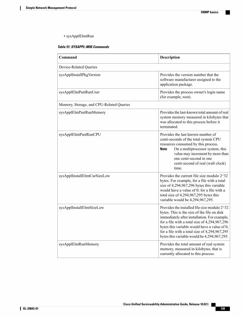
• sysApplElmtRun
Table 51: SYSAPPL-MIB Commands
DescriptionCommand
Device-Related Queries
Provides the version number that thesoftware manufacturer assigned to theapplication package.
sysApplInstallPkgVersion
Provides the process owner's login name(for example, root).
sysApplElmPastRunUser
Memory, Storage, and CPU-Related Queries
Provides the last-known total amount of realsystem memory measured in kilobytes thatwas allocated to this process before itterminated.
sysApplElmPastRunMemory
Provides the last known number ofcenti-seconds of the total system CPUresources consumed by this process.
On a multiprocessor system, thisvalue may increment by more thanone centi-second in onecenti-second of real (wall clock)time.
Note
sysApplElmtPastRunCPU
Provides the current file size modulo 2^32bytes. For example, for a file with a totalsize of 4,294,967,296 bytes this variablewould have a value of 0; for a file with atotal size of 4,294,967,295 bytes thisvariable would be 4,294,967,295.
sysApplInstallElmtCurSizeLow
Provides the installed file size modulo 2^32bytes. This is the size of the file on diskimmediately after installation. For example,for a file with a total size of 4,294,967,296bytes this variable would have a value of 0;for a file with a total size of 4,294,967,295bytes this variable would be 4,294,967,295.
sysApplInstallElmtSizeLow
Provides the total amount of real systemmemory, measured in kilobytes, that iscurrently allocated to this process.
sysApplElmRunMemory
Cisco Unified Serviceability Administration Guide, Release 10.0(1) OL-29842-01 139
Simple Network Management ProtocolSNMP basics

Provides the number of centi-seconds of thetotal system CPU resources consumed bythis process.
On a multiprocessor system, thisvalue may have been incrementedby more than one centi-second inone centi-second of real (wallclock) time.
Note
sysApplElmRunCPU
Process-Related Queries
Provides the current state of the runningprocess. The possible values are running(1),runnable(2) but waiting for a resource suchas CPU, waiting(3) for an event, exiting(4),or other(5).
sysApplElmtRunState
Provides the number of regular filescurrently opened by the process. Transportconnections (sockets) should not be includedin the calculation of this value, nor shouldoperating-system-specific special file types.
sysApplElmtRunNumFiles
Provides the time the process was started.sysApplElmtRunTimeStarted
Provides the total amount of real systemmemory, measured in kilobytes, that iscurrently allocated to this process.
sysApplElmtRunMemory
Provides the index into the installed elementtable. The value of this object is the samevalue as the sysApplInstallElmtIndex forthe application element of which this entryrepresents a previously executed process.
sysApplElmtPastRunInstallID
Provides the process owner's login name(for example, root).
sysApplElmtPastRunUser
Provides the time the process ended.sysApplElmtPastRunTimeEnded
Provides the process owner's login name(for example, root).
sysApplElmtRunUser
Provides the date and time that theapplication was started.
sysApplRunStarted
Provides the number of centi-seconds of thetotal system CPU resources consumed bythis process.
On a multiprocessor system, thisvalue may have been incrementedby more than one centi-second inone centi-second of real (wallclock) time.
Note
sysApplElmtRunCPU
Cisco Unified Serviceability Administration Guide, Release 10.0(1)140 OL-29842-01
Simple Network Management ProtocolSNMP basics
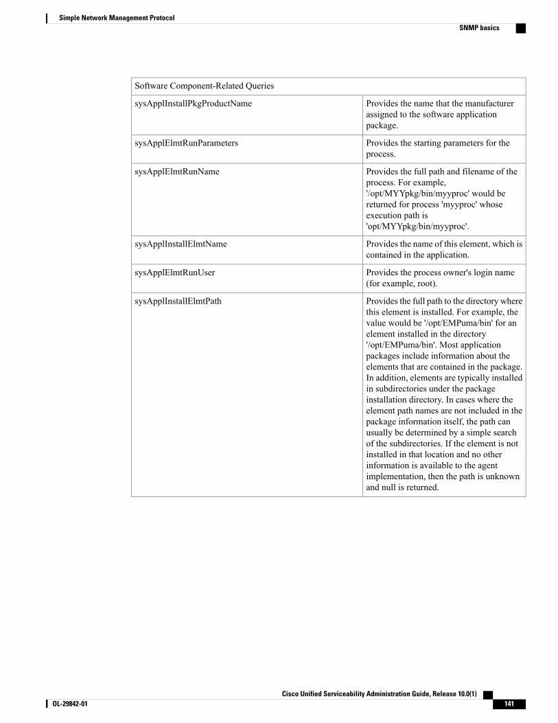
Software Component-Related Queries
Provides the name that the manufacturerassigned to the software applicationpackage.
sysApplInstallPkgProductName
Provides the starting parameters for theprocess.
sysApplElmtRunParameters
Provides the full path and filename of theprocess. For example,'/opt/MYYpkg/bin/myyproc' would bereturned for process 'myyproc' whoseexecution path is'opt/MYYpkg/bin/myyproc'.
sysApplElmtRunName
Provides the name of this element, which iscontained in the application.
sysApplInstallElmtName
Provides the process owner's login name(for example, root).
sysApplElmtRunUser
Provides the full path to the directory wherethis element is installed. For example, thevalue would be '/opt/EMPuma/bin' for anelement installed in the directory'/opt/EMPuma/bin'. Most applicationpackages include information about theelements that are contained in the package.In addition, elements are typically installedin subdirectories under the packageinstallation directory. In cases where theelement path names are not included in thepackage information itself, the path canusually be determined by a simple searchof the subdirectories. If the element is notinstalled in that location and no otherinformation is available to the agentimplementation, then the path is unknownand null is returned.
sysApplInstallElmtPath
Cisco Unified Serviceability Administration Guide, Release 10.0(1) OL-29842-01 141
Simple Network Management ProtocolSNMP basics

Provides the value of this object andidentifies the installed software package forthe application of which this process is apart. Provided that the parent application ofthe process can be determined, the value ofthis object is the same value as thesysApplInstallPkgIndex for the entry in thesysApplInstallPkgTable that corresponds tothe installed application of which thisprocess is a part. If, however, the parentapplication cannot be determined (forexample, the process is not part of aparticular installed application), the valuefor this object is then '0', signifying that thisprocess cannot be related back to anapplication, and in turn, an installedsoftware package.
sysApplMapInstallPkgIndex
Provides the index into thesysApplInstallElmtTable. The value of thisobject is the same value as thesysApplInstallElmtIndex for the applicationelement of which this entry represents arunning instance. If this process cannot beassociated with an installed executable, thevalue should be '0'.
sysApplElmtRunInstallID
Provides the current state of the runningapplication instance. The possible valuesare running(1), runnable(2) but waiting fora resource such as CPU, waiting(3) for anevent, exiting(4), or other(5). This value isbased on an evaluation of the runningelements of this application instance (seesysApplElmRunState) and their Roles asdefined by sysApplInstallElmtRole. Anagent implementation may detect that anapplication instance is in the process ofexiting if one or more of its REQUIREDelements are no longer running. Most agentimplementations will wait until a secondinternal poll is completed to give the systemtime to start REQUIRED elements beforemarking the application instance as exiting.
sysApplRunCurrentState
Provides the date and time this softwareapplication was installed on the host.
sysApplInstallPkgDate
Provides the version number that thesoftware manufacturer assigned to theapplication package.
sysApplInstallPkgVersion
Cisco Unified Serviceability Administration Guide, Release 10.0(1)142 OL-29842-01
Simple Network Management ProtocolSNMP basics

Provides the type of element that is part ofthe installed application.
sysApplInstallElmtType
Date/Time-Related Queries
The number of centi-seconds of the totalsystem CPU resources consumed by thisprocess
On a multiprocessor system, thisvalue may have been incrementedby more than one centi-second inone centi-second of real (wallclock) time.
Note
sysApplElmtRunCPU
Provides the date and time this softwareapplication is installed on the host.
sysApplInstallPkgDate
Provides the time the process ended.sysApplElmtPastRunTimeEnded
Provides the date and time that theapplication was started.
sysApplRunStarted
MIB-II
UseMIB2 agent to get information fromMIB-II. TheMIB2 agent provides access to variables that are definedin RFC 1213, such as interfaces, IP, and so on, and supports the following groups of objects:
• system
• interfaces
• at
• ip
• icmp
• tcp
• udp
• snmp
Table 52: MIB-II Commands
DescriptionCommand
Device-Related Queries
Provides an administratively assigned name for thismanaged node. By convention, this name is the fullyqualified domain name of the node. If the name isunknown, the value is the zero-length string.
sysName
Cisco Unified Serviceability Administration Guide, Release 10.0(1) OL-29842-01 143
Simple Network Management ProtocolSNMP basics

Provides a textual description of the entity. This valueshould include the full name and versionidentification of the system hardware type, softwareoperating-system, and networking software.
sysDescr
SNMP Diagnostic Queries
Provides an administratively assigned name for thismanaged node. By convention, this name is thefully-qualified domain name of the node. If the nameis unknown, the value is the zero-length string.
sysName
Provides the time (in hundredths of a second) sincethe network management portion of the system waslast reinitialized.
sysUpTime
Provides the total number of MIB objects that wereretrieved successfully by the SNMP protocol entityas the result of receiving valid SNMP Get-Requestand Get-Next PDUs.
snmpInTotalReqVars
Provides the total number of SNMP Messages thatwere passed from the SNMP entity to the transportservice.
snmpOutPkts
Provides a value that indicates the set of services thatthis entity potentially offers. The value is a sum. Thissum initially takes the value zero, then, for each layer,L, in the range 1 through 7, that this node performstransactions for, 2 raised to (L - 1) is added to thesum. For example, a node which is a host offeringapplication services would have a value of 4(2^(3-1)). In contrast, a node which is a host offeringapplication services would have a value of 72(2^(4-1) + 2^(7-1)).
In the context of the Internet suite ofprotocols, calculate: layer 1 physical (forexample, repeaters), layer 2datalink/subnetwork (for example, bridges),layer 3 internet (supports IP), layer 4end-to-end (supports TCP), layer 7applications (supports SMTP).
For systems including OSI protocols, youcan also count layers 5 and 6.
Note
sysServices
Cisco Unified Serviceability Administration Guide, Release 10.0(1)144 OL-29842-01
Simple Network Management ProtocolSNMP basics
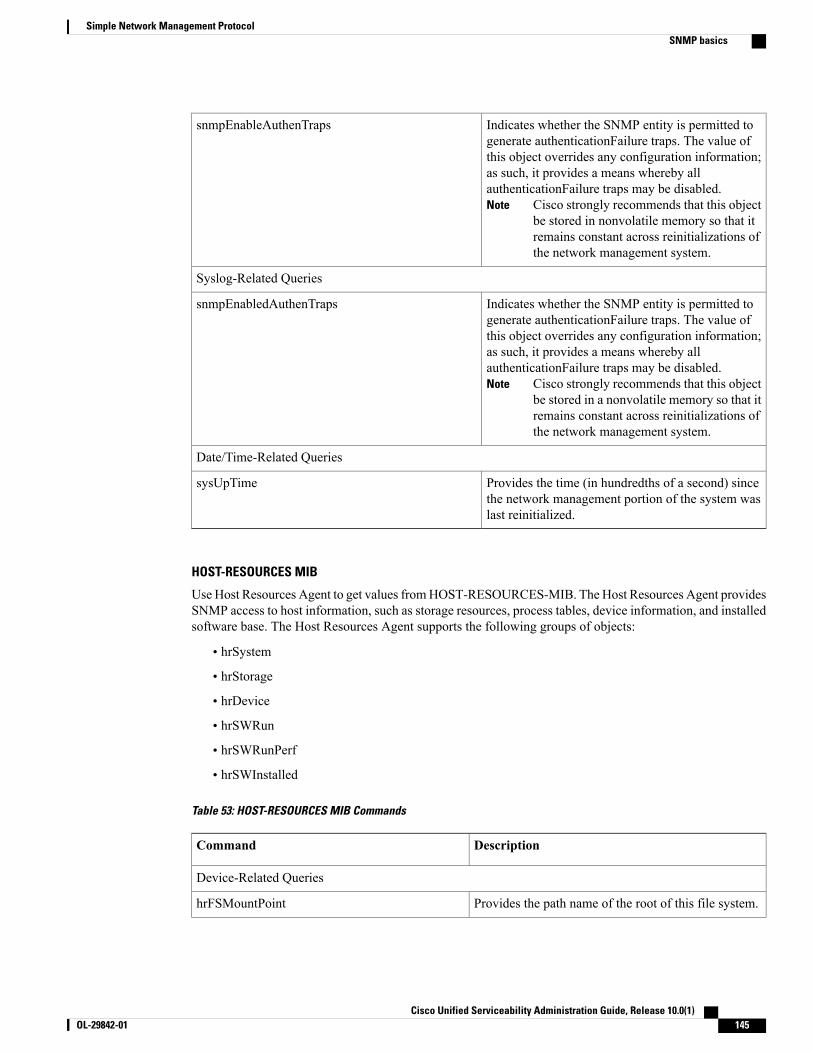
Indicates whether the SNMP entity is permitted togenerate authenticationFailure traps. The value ofthis object overrides any configuration information;as such, it provides a means whereby allauthenticationFailure traps may be disabled.
Cisco strongly recommends that this objectbe stored in nonvolatile memory so that itremains constant across reinitializations ofthe network management system.
Note
snmpEnableAuthenTraps
Syslog-Related Queries
Indicates whether the SNMP entity is permitted togenerate authenticationFailure traps. The value ofthis object overrides any configuration information;as such, it provides a means whereby allauthenticationFailure traps may be disabled.
Cisco strongly recommends that this objectbe stored in a nonvolatile memory so that itremains constant across reinitializations ofthe network management system.
Note
snmpEnabledAuthenTraps
Date/Time-Related Queries
Provides the time (in hundredths of a second) sincethe network management portion of the system waslast reinitialized.
sysUpTime
HOST-RESOURCES MIB
Use Host Resources Agent to get values fromHOST-RESOURCES-MIB. The Host Resources Agent providesSNMP access to host information, such as storage resources, process tables, device information, and installedsoftware base. The Host Resources Agent supports the following groups of objects:
• hrSystem
• hrStorage
• hrDevice
• hrSWRun
• hrSWRunPerf
• hrSWInstalled
Table 53: HOST-RESOURCES MIB Commands
DescriptionCommand
Device-Related Queries
Provides the path name of the root of this file system.hrFSMountPoint
Cisco Unified Serviceability Administration Guide, Release 10.0(1) OL-29842-01 145
Simple Network Management ProtocolSNMP basics

Provides a textual description of this device, includingthe device manufacturer and revision, and optionally,the serial number.
hrDeviceDescr
Provides a description of the type and instance of thestorage.
hrStorageDescr
Memory, Storage, and CPU Related Queries
Provides the amount of physical read-write mainmemory, typically RAM, that the host contains.
hrMemorySize
Provides the size of the storage, in units ofhrStorageAllocationUnits.This object is writable toallow remote configuration of the size of the storagearea in those cases where such an operationmakes senseand is possible on the underlying system. For example,you can modify the amount of main memory allocatedto a buffer pool or the amount of disk space allocatedto virtual memory.
hrStorageSize
Process-Related Queries
Provides a textual description of this running piece ofsoftware, including the manufacturer, revision, and thename by which it is commonly known. If this softwareis installed locally, it must be the same string as usedin the corresponding hrSWInstalledName.
hrSWRunName
Provides the number of process contexts that arecurrently loaded or running on this system.
hrSystemProcesses
Provides a unique value for each piece of software thatis running on the host. Wherever possible, use thenative, unique identification number of the system.
hrSWRunIndex
Software Component-Related Queries
Provides a textual description of this installed piece ofsoftware, including themanufacturer, revision, the nameby which it is commonly known, and optionally, theserial number.
hrSWInstalledName
Provides a description of the location of long-termstorage (for example, a disk drive) from which thissoftware was loaded.
hrSWRunPath
Date/Time-Related Queries
Provides the host local date and time of day.hrSystemDate
Cisco Unified Serviceability Administration Guide, Release 10.0(1)146 OL-29842-01
Simple Network Management ProtocolSNMP basics

Provides the last date at which a portion of this filesystemwas copied to another storage device for backup.This information is useful for ensuring that backups arebeing performed regularly. If this information is notknown, then this variable will have the valuecorresponding to January 1, year 0000, 00:00:00.0,which is encoded as (hex)'00 00 01 01 00 00 00 00'.
hrFSLastPartialBackupDate
CISCO-SYSLOG-MIB
Syslog tracks and logs all system messages, from informational through critical. With this MIB, networkmanagement applications can receive syslog messages as SNMP traps:
The Cisco Syslog Agent supports trap functionality with the following MIB objects:
• clogNotificationsSent
• clogNotificationsEnabled
• clogMaxSeverity
• clogMsgIgnores
• clogMsgDrops
The CISCO-SYSLOG-MIB is dependent on the presence of the CISCO-SMI MIB.Note
Table 54: CISCO-SYSLOG-MIB Commands
DescriptionCommand
Syslog-Related Queries
Indicates whether clogMessageGeneratednotifications will be sent when the device generatesa syslog message. Disabling notifications does notprevent syslog messages from being added to theclogHistoryTable.
clogNotificationEnabled
Indicates which syslog severity levels will beprocessed. The agent will ignore any syslog messagewith a severity value greater than this value.
Severity numeric values increase as theirseverity decreases. For example, error (4)is more severe than debug (8).
Note
clogMaxSeverity
CISCO-CCM-MIB/CISCO-CCM-CAPABILITY MIB
The CISCO-CCM-MIB contains both dynamic (real-time) and configured (static) information about the CiscoUnified Communications Manager and its associated devices, such as phones, gateways, and so on, that are
Cisco Unified Serviceability Administration Guide, Release 10.0(1) OL-29842-01 147
Simple Network Management ProtocolSNMP basics
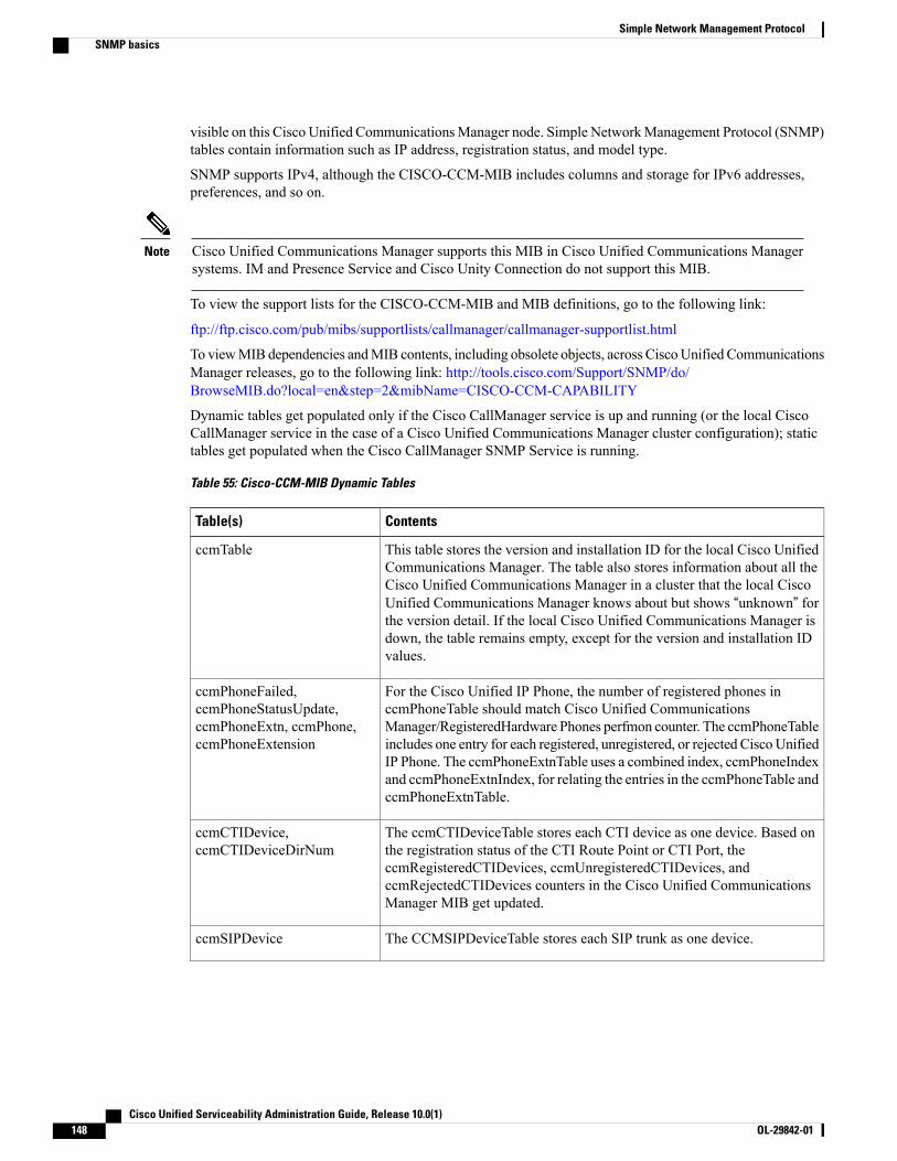
visible on this Cisco Unified CommunicationsManager node. Simple NetworkManagement Protocol (SNMP)tables contain information such as IP address, registration status, and model type.
SNMP supports IPv4, although the CISCO-CCM-MIB includes columns and storage for IPv6 addresses,preferences, and so on.
Cisco Unified Communications Manager supports this MIB in Cisco Unified Communications Managersystems. IM and Presence Service and Cisco Unity Connection do not support this MIB.
Note
To view the support lists for the CISCO-CCM-MIB and MIB definitions, go to the following link:
ftp://ftp.cisco.com/pub/mibs/supportlists/callmanager/callmanager-supportlist.html
To viewMIB dependencies andMIB contents, including obsolete objects, across CiscoUnified CommunicationsManager releases, go to the following link: http://tools.cisco.com/Support/SNMP/do/BrowseMIB.do?local=en&step=2&mibName=CISCO-CCM-CAPABILITY
Dynamic tables get populated only if the Cisco CallManager service is up and running (or the local CiscoCallManager service in the case of a Cisco Unified Communications Manager cluster configuration); statictables get populated when the Cisco CallManager SNMP Service is running.
Table 55: Cisco-CCM-MIB Dynamic Tables
ContentsTable(s)
This table stores the version and installation ID for the local Cisco UnifiedCommunications Manager. The table also stores information about all theCisco Unified Communications Manager in a cluster that the local CiscoUnified Communications Manager knows about but shows “unknown” forthe version detail. If the local Cisco Unified Communications Manager isdown, the table remains empty, except for the version and installation IDvalues.
ccmTable
For the Cisco Unified IP Phone, the number of registered phones inccmPhoneTable should match Cisco Unified CommunicationsManager/RegisteredHardware Phones perfmon counter. The ccmPhoneTableincludes one entry for each registered, unregistered, or rejected CiscoUnifiedIP Phone. The ccmPhoneExtnTable uses a combined index, ccmPhoneIndexand ccmPhoneExtnIndex, for relating the entries in the ccmPhoneTable andccmPhoneExtnTable.
ccmPhoneFailed,ccmPhoneStatusUpdate,ccmPhoneExtn, ccmPhone,ccmPhoneExtension
The ccmCTIDeviceTable stores each CTI device as one device. Based onthe registration status of the CTI Route Point or CTI Port, theccmRegisteredCTIDevices, ccmUnregisteredCTIDevices, andccmRejectedCTIDevices counters in the Cisco Unified CommunicationsManager MIB get updated.
ccmCTIDevice,ccmCTIDeviceDirNum
The CCMSIPDeviceTable stores each SIP trunk as one device.ccmSIPDevice
Cisco Unified Serviceability Administration Guide, Release 10.0(1)148 OL-29842-01
Simple Network Management ProtocolSNMP basics
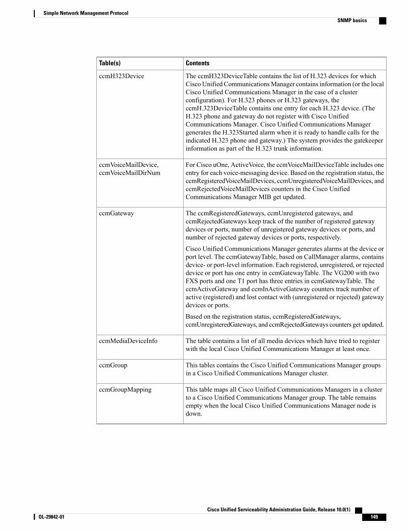
ContentsTable(s)
The ccmH323DeviceTable contains the list of H.323 devices for whichCisco Unified CommunicationsManager contains information (or the localCisco Unified Communications Manager in the case of a clusterconfiguration). For H.323 phones or H.323 gateways, theccmH.323DeviceTable contains one entry for each H.323 device. (TheH.323 phone and gateway do not register with Cisco UnifiedCommunications Manager. Cisco Unified Communications Managergenerates the H.323Started alarm when it is ready to handle calls for theindicated H.323 phone and gateway.) The system provides the gatekeeperinformation as part of the H.323 trunk information.
ccmH323Device
For Cisco uOne, ActiveVoice, the ccmVoiceMailDeviceTable includes oneentry for each voice-messaging device. Based on the registration status, theccmRegisteredVoiceMailDevices, ccmUnregisteredVoiceMailDevices, andccmRejectedVoiceMailDevices counters in the Cisco UnifiedCommunications Manager MIB get updated.
ccmVoiceMailDevice,ccmVoiceMailDirNum
The ccmRegisteredGateways, ccmUnregistered gateways, andccmRejectedGateways keep track of the number of registered gatewaydevices or ports, number of unregistered gateway devices or ports, andnumber of rejected gateway devices or ports, respectively.
Cisco Unified Communications Manager generates alarms at the device orport level. The ccmGatewayTable, based on CallManager alarms, containsdevice- or port-level information. Each registered, unregistered, or rejecteddevice or port has one entry in ccmGatewayTable. The VG200 with twoFXS ports and one T1 port has three entries in ccmGatewayTable. TheccmActiveGateway and ccmInActiveGateway counters track number ofactive (registered) and lost contact with (unregistered or rejected) gatewaydevices or ports.
Based on the registration status, ccmRegisteredGateways,ccmUnregisteredGateways, and ccmRejectedGateways counters get updated.
ccmGateway
The table contains a list of all media devices which have tried to registerwith the local Cisco Unified Communications Manager at least once.
ccmMediaDeviceInfo
This tables contains the Cisco Unified Communications Manager groupsin a Cisco Unified Communications Manager cluster.
ccmGroup
This table maps all Cisco Unified Communications Managers in a clusterto a Cisco Unified Communications Manager group. The table remainsempty when the local Cisco Unified Communications Manager node isdown.
ccmGroupMapping
Cisco Unified Serviceability Administration Guide, Release 10.0(1) OL-29842-01 149
Simple Network Management ProtocolSNMP basics

Table 56: CISCO-CCM-MIB Static Tables
ContentTable(s)
The table contains the list of product types that aresupported with Cisco Unified CommunicationsManager (or cluster, in the case of a Cisco UnifiedCommunications Manager cluster configuration),including phone types, gateway types, media devicetypes, H.323 device types, CTI device types,voice-messaging device types, and SIP device types.
ccmProductType
ccmRegionTable contains the list of all geographicallyseparated regions in a Cisco CommunicationsNetwork (CCN) system. The ccmRegionPairTablecontains the list of geographical region pairs for aCisco Unified Communications Manager cluster.Geographical region pairs are defined by Sourceregion and Destination region.
ccmRegion, ccmRegionPair
The table contains the list of all time zone groups ina Cisco Unified Communications Manager cluster.
ccmTimeZone
The tables contains the list of all device pools in aCisco Unified Communications Manager cluster.Device pools are defined by Region, Date/TimeGroup, and Cisco Unified CommunicationsManagerGroup.
ccmDevicePool
‘The “ccmAlarmConfigInfo” and “ccmQualityReportAlarmConfigInfo” groups in the CISCO-CCM-MIBdefine the configuration parameters that relate to the notifications that are described.
Note
CISCO-UNITY-MIB
The CISCO-UNITY-MIB uses the Connection SNMPAgent to get information about Cisco Unity Connection.
To view the CISCO-UNITY-MIB definitions, go to the following link and click SNMP V2 MIBs:
http://www.cisco.com/public/sw-center/netmgmt/cmtk/mibs.shtml
Cisco Unity Connection supports thisMIB. Cisco Unified CommunicationsManager and IM and PresenceService do not support this MIB.
Note
The Connection SNMP Agent supports the following objects.
Cisco Unified Serviceability Administration Guide, Release 10.0(1)150 OL-29842-01
Simple Network Management ProtocolSNMP basics

Table 57: CISCO-UNITY-MIB Objects
DescriptionObject
This table contains general information about the Cisco Unity Connectionservers such as hostname and version number.
ciscoUnityTable
This table contains general information about the Cisco Unity Connectionvoice messaging ports.
ciscoUnityPortTable
This group contains information about capacity and utilization of the CiscoUnity Connection voice messaging ports.
General Unity Usage Infoobjects
Set up SNMPThe following procedures provides an overview of the steps for configuring SNMP.
Procedure
Step 1 Install and configure the SNMP NMS.Step 2 In the Control Center - Network Services window, verify that the system started the SNMP services.Step 3 Unified CommunicationsManager: In the Service Activationwindow, activate the Cisco CallManager SNMP
service. Cisco Unity Connection only: The Connection SNMP Agent service automatically activates.Step 4 If you are using SNMP V1/V2c, configure the community string.Step 5 If you are using SNMP V3, configure the SNMP user.Step 6 Configure the notification destination for traps or informs.Step 7 Configure the system contact and location for the MIB2 system group.Step 8 Configure trap settings for CISCO-SYSLOG-MIB.Step 9 Unified Communications Manager only: Configure trap settings for CISCO-CCM-MIB.Step 10 Restart the Master Agent service.Step 11 On the NMS, configure the Cisco Unified Communications Manager trap parameters.
Troubleshooting SNMPReview this section for troubleshooting tips. Make sure that all of the feature and network services are running.
Problem
You cannot poll any MIBs from the system.
This condition means that the community string or the snmp user is not configured on the system or they donot match with what is configured on the system. By default, no community string or user is configured onthe system.
Cisco Unified Serviceability Administration Guide, Release 10.0(1) OL-29842-01 151
Simple Network Management ProtocolSet up SNMP

Solution
Check whether the community string or snmp user is properly configured on the system by using the SNMPconfiguration windows.
Problem
You cannot receive any notifications from the system.
This condition means that the notification destination is not configured correctly on the system.
Solution
Verify that you configured the notification destination properly in the Notification Destination (V1/V2c orV3) Configuration window.
SNMP configuration requirementsThe system provides no default SNMP configuration. You must configure SNMP settings after installationto access MIB information. Cisco supports SNMP V1, V2c, and V3 versions.
SNMP agent provides security with community names and authentication traps. You must configure acommunity name to access MIB information. The following table provides the required SNMP configurationsettings.
Table 58: SNMP Configuration Requirements
Cisco Unified Serviceability PageConfiguration
SNMP > V1/V2c > Community StringV1/V2c Community String
SNMP > V3 > UserV3 Community String
SNMP > SystemGroup >MIB2 System GroupSystem Contact and Location for MIB2
SNMP > V1/V2c > Notification DestinationTrap Destinations (V1/V2c)
SNMP > V3 > Notification DestinationTrap Destinations (V3)
SNMP Version 1 supportSNMP Version 1 (SNMPv1), the initial implementation of SNMP that functions within the specifications ofthe Structure of Management Information (SMI), operates over protocols, such as User Datagram Protocol(UDP) and Internet Protocol (IP).
The SNMPv1 SMI defines highly structured tables (MIBs) that are used to group the instances of a tabularobject (that is, an object that contains multiple variables). Tables contain zero or more rows, which are indexed,so SNMP can retrieve or alter an entire row with a supported command.
With SNMPv1, the NMS issues a request, andmanaged devices return responses. Agents use the Trap operationto asynchronously inform the NMS of a significant event.
In the serviceability GUI, you configure SNMPv1 support in the V1/V2c Configuration window.
Cisco Unified Serviceability Administration Guide, Release 10.0(1)152 OL-29842-01
Simple Network Management ProtocolSNMP configuration requirements
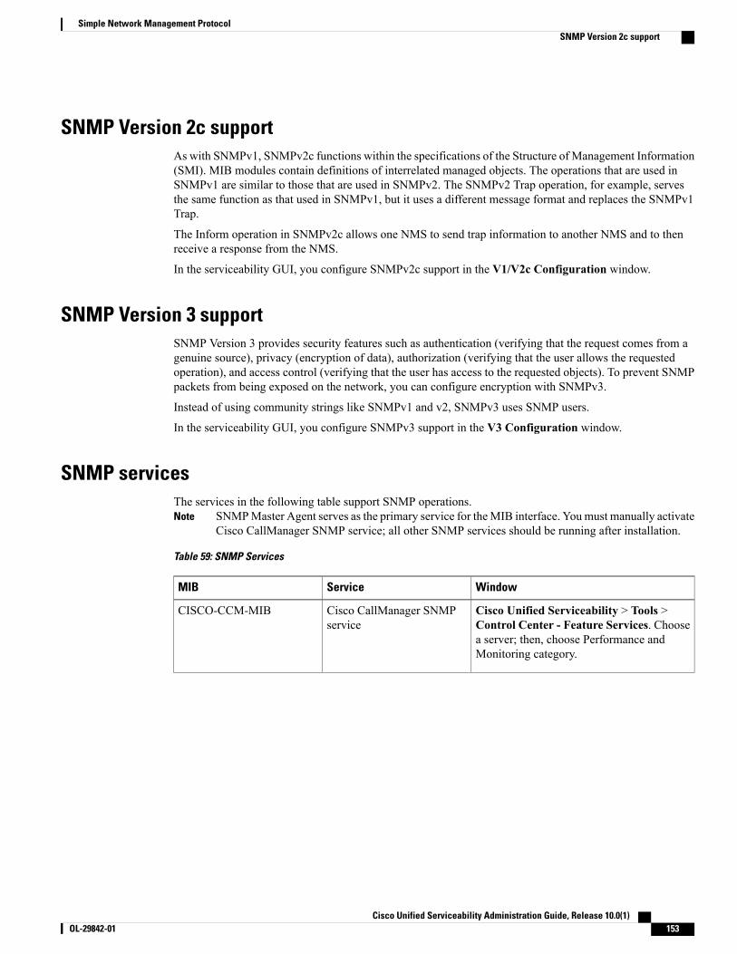
SNMP Version 2c supportAs with SNMPv1, SNMPv2c functions within the specifications of the Structure of Management Information(SMI). MIB modules contain definitions of interrelated managed objects. The operations that are used inSNMPv1 are similar to those that are used in SNMPv2. The SNMPv2 Trap operation, for example, servesthe same function as that used in SNMPv1, but it uses a different message format and replaces the SNMPv1Trap.
The Inform operation in SNMPv2c allows one NMS to send trap information to another NMS and to thenreceive a response from the NMS.
In the serviceability GUI, you configure SNMPv2c support in the V1/V2c Configuration window.
SNMP Version 3 supportSNMP Version 3 provides security features such as authentication (verifying that the request comes from agenuine source), privacy (encryption of data), authorization (verifying that the user allows the requestedoperation), and access control (verifying that the user has access to the requested objects). To prevent SNMPpackets from being exposed on the network, you can configure encryption with SNMPv3.
Instead of using community strings like SNMPv1 and v2, SNMPv3 uses SNMP users.
In the serviceability GUI, you configure SNMPv3 support in the V3 Configuration window.
SNMP servicesThe services in the following table support SNMP operations.
SNMPMaster Agent serves as the primary service for theMIB interface. Youmust manually activateCisco CallManager SNMP service; all other SNMP services should be running after installation.
Note
Table 59: SNMP Services
WindowServiceMIB
Cisco Unified Serviceability > Tools >Control Center - Feature Services. Choosea server; then, choose Performance andMonitoring category.
Cisco CallManager SNMPservice
CISCO-CCM-MIB
Cisco Unified Serviceability Administration Guide, Release 10.0(1) OL-29842-01 153
Simple Network Management ProtocolSNMP Version 2c support

WindowServiceMIB
Cisco Unified Serviceability > Tools >Control Center - Network Services.Choosea server; then, choose Platform Servicescategory.
Cisco Unified IM and PresenceServiceability > Tools > Control Center -Network Services. Choose a server; then,choose Platform Services category.
SNMP Master AgentSNMP Agent
Cisco CDP AgentCISCO-CDP-MIB
System Application AgentSYSAPPL-MIB
MIB2 AgentMIB-II
Host Resources AgentHOST-RESOURCES-MIB
Cisco Syslog AgentCISCO-SYSLOG-MIB
Native Agent AdaptorHardware MIBs
Cisco Unity Connection Serviceability >Tools > Service Management. Choose aserver; then, choose Base Services category.
Connection SNMP AgentCISCO-UNITY-MIB
Stopping any SNMP service may result in loss of data because the network management system no longermonitors the Cisco Unified Communications Manager or Cisco Unity Connection network. Do not stopthe services unless your technical support team tells you to do so.
Caution
SNMP community strings and usersAlthough SNMP community strings provide no security, they authenticate access toMIB objects and functionas embedded passwords. You configure SNMP community strings for SNMPv1 and v2c only.
SNMPv3 does not use community strings. Instead, version 3 uses SNMP users. These users serve the samepurpose as community strings, but users provide security because you can configure encryption or authenticationfor them.
In the serviceability GUI, no default community string or user exists.
SNMP traps and informsAn SNMP agent sends notifications to NMS in the form of traps or informs to identify important systemevents. Traps do not receive acknowledgments from the destination, whereas informs do receiveacknowledgments. You configure the notification destinations by using the SNMP Notification DestinationConfiguration windows in the serviceability GUI.
Cisco Unified CommunicationsManager supports SNMP traps in Cisco Unified CommunicationsManagerand IM and Presence Service systems.
Note
Cisco Unified Serviceability Administration Guide, Release 10.0(1)154 OL-29842-01
Simple Network Management ProtocolSNMP community strings and users

For SNMP notifications, the system sends traps immediately if the corresponding trap flags are enabled. Inthe case of the syslog agent, alarms and system level log messages get sent to syslog daemon for logging.Also, some standard third-party applications send the log messages to syslog daemon for logging. These logmessages get logged locally in the syslog files and also get converted into SNMP traps/notifications.
The following list contains Cisco Unified Communications Manager SNMP trap/inform messages that aresent to a configured trap destination:
• Cisco Unified Communications Manager failed
• Phone failed
• Phones status update
• Gateway failed
• Media resource list exhausted
• Route list exhausted
• Gateway layer 2 change
• Quality report
• Malicious call
• Syslog message generated
Before you configure notification destination, verify that the required SNMP services are activated andrunning. Also, make sure that you configured the privileges for the community string/user correctly.
You configure the SNMP trap destination by choosing SNMP > V1/V2 > Notification Destination orSNMP > V3 > Notification Destination in the serviceability GUI.
Tip
The following table provides information about trap/inform parameters that you configure on the NetworkManagement System (NMS). You can configure the values in the table by issuing the appropriate commandson the NMS, as described in the SNMP product documentation that supports the NMS.
All the parameters that are listed in the table are part of CISCO-CCM-MIB except for the last twoparameters. The last two, clogNotificationsEnabled and clogMaxSeverity, comprise part ofCISCO-SYSLOG-MIB.
Note
For IM and Presence Service, you configure only clogNotificationsEnabled and clogMaxSeverity trap/informparameters on the NMS.
Table 60: Cisco Unified Communications Manager Trap/Inform Configuration Parameters
Configuration RecommendationsGenerated TrapsDefault ValueParameter Name
Keep the default specification.ccmCallManagerFailed
ccmMediaResourceListExhausted
ccmRouteListExhausted
ccmTLSConnectionFailure
TrueccmCallManagerAlarmEnable
Cisco Unified Serviceability Administration Guide, Release 10.0(1) OL-29842-01 155
Simple Network Management ProtocolSNMP traps and informs

Configuration RecommendationsGenerated TrapsDefault ValueParameter Name
None. The default specifies this trapas enabled.
ccmGatewayFailed
ccmGatewayLayer2Change
Although you can configure aCisco ATA 186 device as a phone inCisco Unified CommunicationsManager Administration, when CiscoUnified Communications Managersends SNMP traps for the Cisco ATAdevice, it sends a gateway type trap;for example, ccmGatewayFailed.
TrueccmGatewayAlarmEnable
Set theccmPhoneStatusUpdateAlarmIntervalto a value between 30 and 3600.
ccmPhoneStatusUpdate1800
0
ccmPhoneStatusUpdateStorePeriod
ccmPhoneStatusUpdateAlarmInterval
Set theccmPhoneFailedAlarmInterval to avalue between 30 and 3600.
ccmPhoneFailed1800
0
ccmPhoneFailedStorePeriod
ccmPhoneFailedAlarmInterval
None. The default specifies this trapas enabled.
ccmMaliciousCallTrueccmMaliciousCallAlarmEnable
None. The default specifies this trapas enabled.
This trap gets generated only if theCisco Extended Functions service isactivated and running on the server,or, in the case of a clusterconfiguration (Cisco UnifiedCommunications Manager only), onthe local Cisco UnifiedCommunications Manager server.
ccmQualityReport
TrueccmQualityReportAlarmEnable
To enable trap generation, setclogNotificationsEnable to True.
clogMessageGeneratedFalseclogNotificationsEnabled
When you set clogMaxSeverity towarning, a SNMP trap generateswhen applications generate a syslogmessage with at least a warningseverity level.
clogMessageGeneratedWarningclogMaxSeverity
Related Topics
CISCO-CCM-MIB trap parameters, on page 178CISCO-SYSLOG-MIB trap parameters, on page 177
Cisco Unified Serviceability Administration Guide, Release 10.0(1)156 OL-29842-01
Simple Network Management ProtocolSNMP traps and informs

SNMP trace configurationFor Cisco Unified CommunicationsManager, you can configure trace for the Cisco CallManager SNMP agentin the Trace Configuration window in Cisco Unified Serviceability by choosing the Cisco CallManager SNMPService in the Performance and Monitoring Services service group. A default setting exists for all the agents.For Cisco CDP Agent and Cisco Syslog Agent, you use the CLI to change trace settings, as described in theCommand Line Interface Reference Guide for Cisco Unified Solutions.
For Cisco Unity Connection, you can configure trace for the Cisco Unity Connection SNMP agent in theTrace Configuration window in Cisco Unity Connection Serviceability by choosing the Connection SNMPAgent component.
SNMP V1 and V2c setupThis section describes how to configure the SNMP managed device for SNMP V1/V2c.
Find community stringTo find a community string, perform the following procedure.
Before You Begin
Review the tasks in the overview procedure to set up SNMP.
Procedure
Step 1 Select Snmp > V1/V2c > Community String.Step 2 Select the specific search criteria that you want to use for the community string from the Find Community
Strings where Name list box.Step 3 Enter the community string for which you want to search.Step 4 Select the hostname or IP address of the server where the community string exists in the Server list box.Step 5 Select Find.Step 6 (Optional) To apply the configuration from one of the options in the search results to all nodes in a cluster,
check the check box next to the name of the option and check the Apply to All Nodes check box.This step applies to Unified Communications Manager and IM and Presence Service clusters only.
Step 7 Select the community string that you want to view from the list of results.TheAddNew button does not display in the SNMPCommunity String Configurationwindow untilyou select the Find button. If no community strings exist and you want to add want a communitystring, select the Find button and wait for the window to refresh. The Add New button displays.
Tip
Step 8 From the list of results, click the community string that you want to view.
Cisco Unified Serviceability Administration Guide, Release 10.0(1) OL-29842-01 157
Simple Network Management ProtocolSNMP trace configuration
Set up community stringBecause the SNMP agent provides security by using community strings, you must configure the communitystring to access any management information base (MIB) in the SNMPmanaged device's system. Change thecommunity string to limit access to the SNMPmanaged device's system. To add, modify, and delete communitystrings, access the SNMP Community String configuration window.
Procedure
Step 1 Select Snmp > V1/V2c > Community String.Step 2 Select the required server from the Server list box, and then select Find.Step 3 Perform one of the following tasks:
• To add a new community string, click Add New.
TheAddNew button does not display in the SNMPCommunity String Configurationwindowuntil you select the Find button. If no community strings exist and you want to add want acommunity string, selectFind and wait for the window to refresh. TheAddNew button displays.
Tip
• To modify an existing community string, click the name of the community string that you want to editfrom the list of results.
You cannot change the name of the community string or the server.
Step 4 Enter the community string configuration settings.Before you save the configuration, you can click the Clear All button at any time to delete allinformation that you entered for all settings in the window.
Tip
Step 5 After you complete the configuration, click Add New to save a new community string or click Save to savechanges to an existing community string.A message indicates that changes will not take effect until you restart the SNMP master agent.
Step 6 Perform one of the following actions:
• Select OK to restart the SNMP master agent service and effect the changes.
• Select Cancel to continue the configuration without restarting the SNMP master agent.
Cisco recommends that you wait until you finish all the SNMP configuration before you restartthe SNMP master agent service.
Note
The system refreshes and displays the SNMP Community String Configuration window. Thecommunity string that you created displays in the window.
Related Topics
Community string configuration settings, on page 159Start, stop, and restart services in Control Center or CLI, on page 90
Cisco Unified Serviceability Administration Guide, Release 10.0(1)158 OL-29842-01
Simple Network Management ProtocolSet up community string

Community string configuration settingsThe following table describes the community string configuration settings.
Table 61: Community String Configuration Settings
DescriptionField
This setting in the Community String configuration window displays as readonly because you specified the server choice when you performed the procedurein find a community string.
To change the server for the community string, perform the find a communitystring procedure.
Server
Enter a name for the community string. The name can contain up to 32 charactersand can contain any combination of alphanumeric characters, hyphens (-), andunderscore characters (_).
Choose community string names that will be hard for outsiders to figureout.
Tip
When you edit a community string, you cannot change the name of the communitystring.
Community String
To accept SNMP packets from any host, click this button.Accept SNMP Packetsfrom any host
To accept SNMP only from specified hosts, click this button.
In the Host IP Address field, enter a host from which you want to acceptpackets and click Insert. Repeat this process for each host from whichyou want to accept packets. To delete a host, choose that host from theHost IP Addresses list box and click Remove.
Tip
Accept SNMP Packetsonly from these hosts
Cisco Unified Serviceability Administration Guide, Release 10.0(1) OL-29842-01 159
Simple Network Management ProtocolCommunity string configuration settings

DescriptionField
From the drop-down list box, select the appropriate access level from thefollowing list:
ReadOnly
The community string can only read the values of MIB objects.
ReadWrite
The community string can read and write the values of MIB objects.
ReadWriteNotify
The community string can read and write the values of MIB objects andsend MIB object values for a trap and inform messages.
NotifyOnly
The community string can only send MIB object values for a trap andinform messages.
ReadNotifyOnly
The community string can read values of MIB objects and also send thevalues for trap and inform messages.
None
The community string cannot read, write, or send trap information.
To change the trap configuration parameters, you need to configure acommunity string with NotifyOnly, ReadNotifyOnly, or ReadWriteNotifyprivileges.
IM and Presence Service does not support ReadNoticyOnly.
Tip
Access Privileges
To apply the community string to all nodes in the cluster, check this check box.
This field applies to Cisco Unified Communications Manager and IM andPresence Service clusters only.
Apply To All Nodes
Related Topics
Find community string, on page 157
Delete community stringTo delete a community string, perform the following procedure:
Cisco Unified Serviceability Administration Guide, Release 10.0(1)160 OL-29842-01
Simple Network Management ProtocolDelete community string

Procedure
Step 1 Locate the community string.Step 2 Check the community string that you want to delete from the list of matching records.Step 3 Select Delete Selected. A message indicates that the system will delete notification entries that relate to this
community string.Step 4 SelectOK to continue the deletion. A message indicates that changes will not take effect until you restart the
SNMP master agent.Step 5 Perform one of the following actions:
• Select Cancel to continue the configuration without restarting the SNMP master agent.
• Select OK to restart the SNMP master agent service.
Cisco recommends that you wait until you finish all the SNMP configuration before you restartthe SNMP master agent service.
Tip
Related Topics
Start, stop, and restart services in Control Center or CLI, on page 90
Find SNMP V1 and V2c notification destinationTo find a notification destination for V1/V2c, perform the following procedure.
Procedure
Step 1 Choose Snmp > V1/V2c > Notification Destination.The Find/List window displays.
Step 2 From the Find Notification where Destination IP drop-down list box, choose the specific search criteria thatyou want to use to find the notification destination.
Step 3 Enter the notification destination for which you want to search.Step 4 Enter the hostname or IP address of the server that supports the notification destination in the Server list box,
and then click Find.After you click Find, the Add New button displays. After the search results display, the Apply to All Nodescheck box displays.
Step 5 (Optional) Perform one or more of the following actions:
• To apply the configuration from one of the options in the search results to all nodes in the cluster, checkthe name of the option and check Apply to All Nodes.
This step applies to Cisco Unified CommunicationsManager and IM and Presence Service clusters only.
• Select an item in the search results to view the configuration for that item.
Cisco Unified Serviceability Administration Guide, Release 10.0(1) OL-29842-01 161
Simple Network Management ProtocolFind SNMP V1 and V2c notification destination

The Add New button does not display in the SNMP Notification Destination Configurationwindow until you select Find. If no notification destinations exist and you want to add want anotification destination, select Find and then wait for the window to refresh. The Add Newbutton displays.
Note
Set up SNMP V1 and V2c notification destinationTo configure the notification destination (trap/inform receiver) for V1/V2c, perform the following procedure.
Procedure
Step 1 Select Snmp > V1/V2c > Notification Destination.Step 2 Select the required server from the Server list box, and then click Find.Step 3 Perform one of the following tasks:
• To add a new SNMP notification destination, click Add New.
You configure the notification destination for the server that you choose in the Server drop-down listbox in the Find/List window.
The Add New button does not display in the SNMP Notification Destination Configurationwindow until you select the Find button. If no notification destinations exist and you want toadd a notification destination, select Find and then wait for the window to refresh. The AddNew button displays.
Note
• To modify an existing SNMP notification destination, find the notification destination that you want toedit, and then click the name of the SNMP notification destination in the Find/List window results list.
Step 4 Enter the notification destination configuration settings.Before you save the configuration, you can click theClear button at any time to delete all informationthat you entered for all settings in the window.
Tip
Step 5 Perform one of the following actions:
• Select Insert to save a notification destination.
• Select Save to save changes to an existing notification destination. A message indicates that changeswill not take effect until you restart the SNMP master agent.
Step 6 SelectOK to restart the SNMP master agent or selectCancel to continue the configuration without restartingthe SNMP master agent.
Cisco recommends that you wait until you finish the SNMP configuration before you restart theSNMP master agent service.
Note
Related Topics
Find SNMP V1 and V2c notification destination, on page 161
Cisco Unified Serviceability Administration Guide, Release 10.0(1)162 OL-29842-01
Simple Network Management ProtocolSet up SNMP V1 and V2c notification destination

Notification destination settings for SNMP V1 and V2c, on page 163Set up SNMP V1 and V2c notification destination, on page 162Start, stop, and restart services in Control Center or CLI, on page 90
Notification destination settings for SNMP V1 and V2cThe following table describes the notification destination configuration settings for SNMP V1/V2c.
Table 62: Notification Destination Configuration Settings for SNMP V1/V2c
DescriptionField
This setting displays as read only because you specified the server when youperformed the procedure to find a notification destination.
To change the server for the notification destination, perform the procedure tofind a community string.
Server
From the drop-down list box, select the Host IP address of the trap destinationor click Add New. If you click Add New, enter the IP address of the trapdestination.
For existing notification destinations, you cannot modify the host IP addressconfiguration.
Host IP Addresses
In the field, enter the notification-receiving port number on the destination serverthat receives SNMP packets.
Port Number
From the SNMP Version Information pane, click the appropriate SNMP versionradio button, either V1 or V2c, which depends on the version of SNMP that youare using.
• If you choose V1, configure the community string setting.
• If you choose V2c, configure the notification type setting and then configurethe community string.
V1 or V2c
From the drop-down list box, choose the community string name to be used inthe notification messages that this host generates.
Only community strings with minimum notify privileges (ReadWriteNotify orNotify Only) display. If you have not configured a community string with theseprivileges, no options appear in the drop-down list box. If necessary, clickCreateNew uiCommunity String to create a community string.
IM and Presence only: Only community strings with minimum notify privileges(ReadWriteNotify, ReadNotifyOnly, or Notify Only) display. If you have notconfigured a community string with these privileges, no options appear in thedrop-down list box. If necessary, clickCreate NewCommunity String to createa community string.
Community String
From the drop-down list box, choose the appropriate notification type.Notification Type
Cisco Unified Serviceability Administration Guide, Release 10.0(1) OL-29842-01 163
Simple Network Management ProtocolNotification destination settings for SNMP V1 and V2c

DescriptionField
To apply the notification destination configuration to all nodes in the cluster,check this check box.
This applies to Cisco Unified Communications Manager and IM and PresenceService clusters only.
Apply To All Nodes
Related Topics
Find community string, on page 157Find SNMP V1 and V2c notification destination, on page 161Set up community string, on page 158Set up SNMP V1 and V2c notification destination, on page 162
Delete SNMP V1 and V2c notification destinationTo delete an SNMP V1/V2c notification destination, perform the following procedure:
Procedure
Step 1 Find the notification destination that you want to delete.Step 2 Check the check box next to the notification destination that you want to delete in the list of matching records
in the Find/List window.Step 3 Click Delete Selected. A message asks whether you want to delete the notification entries.Step 4 Click OK to continue the deletion. A message indicates that changes will not take effect until you restart the
SNMP master agent.Step 5 Perform one of the following:
• To restart the SNMP master agent service, click OK.
• To continue the configuration without restarting the SNMP master agent, click Cancel.
Cisco recommends that you wait until you finish all the SNMP configuration before you restart theSNMP master agent service.
Tip
After the window refreshes, the notification destination that you deleted no longer displays in the results.
Related Topics
Find SNMP V1 and V2c notification destination, on page 161Start, stop, and restart services in Control Center or CLI, on page 90
SNMP V3 setupThis section describes how to configure the SNMP managed device for SNMP V3.
Cisco Unified Serviceability Administration Guide, Release 10.0(1)164 OL-29842-01
Simple Network Management ProtocolDelete SNMP V1 and V2c notification destination
Find SNMP V3 user
The Add New button does not display in the SNMP User Configuration window until you click the Findbutton. If no users exist and you want to add a user, click the Find button and wait for the window torefresh. The Add New button displays.
Tip
To find a SNMP user, perform the following procedure.
Procedure
Step 1 Select Snmp > V3 > User.Step 2 Select the specific search criteria that you want to use to find the user; for example, begins with.Step 3 Enter the username for which you want to search.Step 4 Select the hostname or IP address of the server where you access the user from the Server list box, and then
click Find.Step 5 (Optional) To apply the configuration from one of the options in the search results to all nodes in the cluster,
check the check box next to the name of the option and check the Apply to All Nodes check box.This applies to Cisco Unified Communications Manager and IM and Presence Service clusters only.
Step 6 Select the user that you want to view from the list of results.
Set up SNMP V3 userTo setup users for SNMP V3, perform the following procedure.
Procedure
Step 1 Select Snmp > V3 > User and locate the SNMP V3 user to set up.See the procedure to find the SNMP V3 user for details.
Step 2 Perform one of the following tasks:
• To add a new SNMP user, click the Add New button in the SNMP User Configuration Find/Listwindow.
• IM and Presence only: To add a new SNMP user, select Snmp > V3 > User > Add New.
The Add New button does not display in the SNMP User Configuration window until youselect the Find button. If no users exist and you want to add want a user, select the Find buttonand wait for the window to refresh. The Add New button displays.
Note
• To modify an existing SNMP user, search for the user in the SNMP User Configuration Find/Listwindow, and then click the name of the SNMP user that you want to modify from the results list.
Step 3 Enter the SNMP V3 user configuration settings.
Cisco Unified Serviceability Administration Guide, Release 10.0(1) OL-29842-01 165
Simple Network Management ProtocolFind SNMP V3 user

Before you save the configuration, you can click the Clear All button at any time to delete allinformation that you entered for all settings in the window.
Tip
Step 4 To add a new user, click Insert, or click Save to save changes to an existing user.A message indicates that changes will not take effect until you restart the SNMP master agent.
Step 5 Perform one of the following:
• To restart the SNMP master agent service, click OK.
• To continue the configuration without restarting the SNMP master agent, click Cancel.
Cisco recommends that you wait until you finish the SNMP configuration before you restart the SNMPmaster agent service.
Tip
To access this server that has the user that you configure, make sure that you configure this user onthe NMS with the appropriate authentication and privacy settings.
Note
Related Topics
Find SNMP V3 user, on page 165SNMP V3 user configuration settings, on page 166Start, stop, and restart services in Control Center or CLI, on page 90
SNMP V3 user configuration settingsThe following table describes the SNMP V3 user configuration settings.
Table 63: SNMP V3 User Configuration Settings
DescriptionField
This setting displays as read only because you specified the server when youperformed the find notification destination procedure.
To change the server where you want to provide access, perform the procedureto find an SNMP user.
Server
In the field, enter the name of the user for which you want to provide access.The name can contain up to 32 characters and can contain any combination ofalphanumeric characters, hyphens (-), and underscore characters (_).
Enter users that you have already configured for the network managementsystem (NMS).
Tip
For existing SNMP users, this setting displays as read only.
User Name
To require authentication, check the check box, enter the password in thePassword and Reenter Password fields, and choose the appropriate protocol. Thepassword must contain at least 8 characters.
Authentication Required
Cisco Unified Serviceability Administration Guide, Release 10.0(1)166 OL-29842-01
Simple Network Management ProtocolSNMP V3 user configuration settings

DescriptionField
If you checked the Authentication Required check box, you can specify privacyinformation. To require privacy, check the check box, enter the password in thePassword and Reenter Password fields, and check the protocol check box. Thepassword must contain at least 8 characters.
After you check the Privacy Required check box, the DES (DataEncryption Standard) check box automatically appears checked. The DESprotocol prevents packets from being disclosed.
Tip
Privacy Required
To accept SNMP packets from any host, click the radio button.Accept SNMP Packetsfrom any host
To accept SNMP packets from specific hosts, click the radio button. In the HostIP Address field, enter a host from which you want to accept SNMP packets andclick Insert. Repeat this process for each host from which you want to acceptSNMP packets. To delete a host, choose that host from the Host IP Addressespane and click Remove.
Accept SNMP Packetsonly from these hosts
From the drop-down list box, choose one of the following options for the accesslevel:
ReadOnly
The user can only read the values of MIB objects.
ReadWrite
The user can read and write the values of MIB objects.
ReadWriteNotify
The user can read and write the values ofMIB objects and sendMIB objectvalues for a trap and inform messages.
NotifyOnly
The user can only send MIB object values for trap and inform messages.
ReadNotifyOnly
The user can read values of MIB objects and also send the values for trapand inform messages.
None
The user cannot read, write, or send trap information.
To change the trap configuration parameters, you need to configure a userwith NotifyOnly, ReadNotifyOnly, or ReadWriteNotify privileges.
Tip
Access Privileges
To apply the user configuration to all nodes in the cluster, check this check box.
This applies to Cisco Unified Communications Manager and IM and PresenceService clusters only.
Apply To All Nodes
Cisco Unified Serviceability Administration Guide, Release 10.0(1) OL-29842-01 167
Simple Network Management ProtocolSNMP V3 user configuration settings
Related Topics
Find SNMP V3 user, on page 165
Delete SNMP V3 userTo delete a user for SNMP, perform the following procedure:
Procedure
Step 1 Select Snmp > V3 > User and locate the SNMP V3 user to delete.See the procedure to find the SNMP V3 user for details.
Step 2 From the list of matching records, check the check box next to the user that you want to delete.Step 3 Click Delete Selected.
A message indicates that the system will delete notification entries that relate to this user.
Step 4 To continue the deletion, click OK.A message indicates that changes will not take effect until you restart the SNMP master agent.
Step 5 Perform one of the following actions:
• Select OK to restart the SNMP master agent service.
• Select Cancel to continue the configuration without restarting the SNMP master agent.
Cisco recommends that you wait until you finish all the SNMP configuration before you restart the SNMPmaster agent service.
After the window refreshes, the user that you deleted no longer displays in the results.
Related Topics
Find SNMP V3 user, on page 165Start, stop, and restart services in Control Center or CLI, on page 90
Find SNMP V3 notification destination
The Add New button does not display in the SNMP Notification Destination Configuration window untilyou click the Find button. If no users exist and you want to add want a user, click the Find button andwait for the window to refresh. The Add New button displays.
Tip
To find a notification destination for V3, perform the following procedure.
Cisco Unified Serviceability Administration Guide, Release 10.0(1)168 OL-29842-01
Simple Network Management ProtocolDelete SNMP V3 user
Procedure
Step 1 Choose Snmp > V3 > Notification Destination.Step 2 From the Find Notification where Destination IP drop-down list box, choose the specific search criteria that
you want to use to find the notification destination; for example, begins with.Step 3 Enter the IP address/hostname of notification destination for which you want to search.Step 4 In the Server field, choose the hostname or IP address of the server that supports the notification destination,
and then click Find.After you click Find, the Add New button displays. After the search results display, the Apply to All Nodescheck box displays.
Step 5 (Optional) To apply the configuration from one of the options in the search results to all nodes in the cluster,check the check box next to the name of the option and then check the Apply to All Nodes check box.This applies to Cisco Unified Communications Manager and IM and Presence Service clusters only.
Step 6 Select the notification destination that you want to view from the list of results.
Set up SNMP V3 notification destinationTo configure the trap/Inform receiver, perform the following procedure.
Procedure
Step 1 Select Snmp >V3 >Notification Destination and locate the notification destination for SNMP V3 to set up.See the procedure to find the notification destination for SNMP V3 for details.
Step 2 Perform one of the following tasks:
• To add a new SNMP notification destination, click the Add New button in the search results window.
• Tomodify an existing SNMP notification destination, click the name of the SNMP notification destinationthat you want to edit in the search results window.
Step 3 Configure the SNMP V3 notification destination configuration settings.Before you save the configuration, you can click theClear button at any time to delete all informationthat you entered for all settings in the window.
Tip
Step 4 Perform one of the following actions to save a notification destination:
• Select Insert to add the notification destination.
• Select Save to save changes to an existing notification destination.
A message indicates that changes will not take effect until you restart the SNMP master agent.
Step 5 Perform one of the following actions:
• To restart the SNMP master agent service, click OK.
Cisco Unified Serviceability Administration Guide, Release 10.0(1) OL-29842-01 169
Simple Network Management ProtocolSet up SNMP V3 notification destination

• To continue the configuration without restarting the SNMP master agent, click Cancel.
Cisco recommends that you wait until you finish the SNMP configuration before you restart the SNMPmaster agent service.
Tip
Related Topics
Find SNMP V3 user, on page 165SNMP V3 user configuration settings, on page 166Start, stop, and restart services in Control Center or CLI, on page 90
Notification destination settings for SNMP V3The following table describes the notification destination configuration settings for SNMP V3.
Table 64: Notification Destination Configuration Settings for SNMP V3
DescriptionField
This setting displays as read only because you specified the server when youperformed the procedure to find an SNMP V3 notification destination.
To change the server for the notification destination, perform the procedure tofind an SNMP V3 notification destination and select a different server.
Server
From the drop-down list box, choose the Host IP address or choose Add New.If you chose Add New, enter the IP address for the host.
Host IP Addresses
In the field, enter the notification-receiving port number on the destination server.Port Number
From the drop-down list box, choose Inform or Trap.
Cisco recommends that you choose the Inform option. The Inform functionretransmits the message until it is acknowledged, thus, making it morereliable than traps.
Tip
Notification Type
This setting displays if you chose Inform from the Notification Type drop-downlist box.
From the drop-down list box, choose the engine ID or choose Add New. If youchose AddNew, enter the ID in the Remote SNMPEngine Id field, which requiresa hexidecimal value.
Remote SNMP Engine Id
Cisco Unified Serviceability Administration Guide, Release 10.0(1)170 OL-29842-01
Simple Network Management ProtocolNotification destination settings for SNMP V3

DescriptionField
From the drop-down list box, choose the appropriate security level for the user.
noAuthNoPriv
No authentication or privacy configured.
authNoPriv
Authentication configured, but no privacy configured.
authPriv
Authentication and privacy configured.
Security Level
From the pane, perform one of the following tasks to associate or disassociatethe notification destination with the user.
1 To create a new user, click Create New User.2 To modify an existing user, click the radio button for the user and then click
Update Selected User.3 To delete a user, click the radio button for the user and then click Delete
Selected User.
The users that display vary depending on the security level that you configuredfor the notification destination.
User Information pane
To apply the notification destination configuration to all nodes in the cluster,check this check box.
This applies to Cisco Unified Communications Manager and IM and PresenceService clusters only.
Apply To All Nodes
Related Topics
Find SNMP V3 user, on page 165
Delete SNMP V3 notification destinationTo delete an SNMP V3 notification destination, perform the following procedure.
Procedure
Step 1 Select Snmp > V3 > Notification Destination and locate the notification destination to delete.See the procedure to find the notification destination for SNMP V3 for details.
Cisco Unified Serviceability Administration Guide, Release 10.0(1) OL-29842-01 171
Simple Network Management ProtocolDelete SNMP V3 notification destination

Step 2 From the list of matching records, check the check box next to the notification destination that you want todelete.
Step 3 Select Delete Selected. A message asks you if you want to delete the notification destination.Step 4 SelectOK to continue the deletion. A message indicates that changes will not take effect until you restart the
SNMP master agent.Step 5 Perform one of the following actions:
• Select OK to restart the SNMP master agent service.
• Select Cancel to continue the configuration without restarting the SNMP master agent.
Cisco recommends that you wait until you finish the SNMP configuration before you restart theSNMP master agent service.
Note
Related Topics
Find SNMP V3 notification destination, on page 168Start, stop, and restart services in Control Center or CLI, on page 90
MIB2 system groupUse the serviceability GUI to configure the system contact and system location objects for the SNMPMIB-IIsystem group. For example, you could enter Administrator, 555-121-6633, for the system contact and SanJose, Bldg 23, 2nd floor, for the system location.
Set up MIB2 system groupPerform the following procedure to configure a system contact and system location for the MIB-II systemgroup.
This procedure supports SNMP v1, v2c, and v3 configuration.Tip
Procedure
Step 1 Choose Snmp > SystemGroup >MIB2 System Group.Step 2 Configure the SNMP MIB2 system group configuration settings.Step 3 Click Save. A message indicates that changes will not take effect until you restart the SNMP master agent.Step 4 Select OK to restart the SNMP master agent service or select Cancel to continue the configuration without
restarting the SNMP master agent.Step 5 Perform one of the following actions:
• Select Clear All to clear the System Contact and System Location fields.
• Select Clear All and Save to delete the system configuration.
Cisco Unified Serviceability Administration Guide, Release 10.0(1)172 OL-29842-01
Simple Network Management ProtocolMIB2 system group

Related Topics
MIB2 system group settings, on page 173
MIB2 system group settingsThe following table describes the MIB2 System Group configuration settings.
Table 65: MIB2 System Group Configuration Settings
DescriptionField
From the drop-down list box, choose the server for which you want toconfigure contacts, and then click Go.
Server
Enter a person to notify when problems occur.System Contact
Enter the location of the person that is identified as the system contact.System Location
Check to apply the system configuration to all of the nodes in the cluster.
This applies to CiscoUnified CommunicationsManager and IM and PresenceService clusters only.
Apply To All Nodes
SNMP trap settingsUse CLI commands to set the configurable SNMP trap settings. SNMP trap configuration parameters andrecommended configuration tips are provided for CISCO-SYSLOG-MIB, CISCO-CCM-MIB, andCISCO-UNITY-MIB.
Set up SNMP trapsTo set up SNMP traps, perform the following steps.
Procedure
Step 1 Login to CiscoUnified Serviceability and confirm that Cisco CallManager SNMPServices and SNMPMasterAgent are activated and running by performing the following steps:a) ChooseTools >Control Center - Feature Services and confirm thatCisco CallManager SNMPServices
is started.b) Choose Tools > Control Center - Network Services and confirm that SNMP Master Agent is started.
Step 2 If you want to run SNMP V1 or V2, confirm that the community string and notification destination is set upby performing the following steps:
Cisco Unified Serviceability Administration Guide, Release 10.0(1) OL-29842-01 173
Simple Network Management ProtocolMIB2 system group settings

a) Follow the Set up community string procedure and make sure that Access Privileges are set to eitherReadWriteNotify, NotifyOnly, or ReadNotify.
b) Follow the Set up notification destination procedure.
Step 3 If you want to run SNMP V3, confirm that the user and notification destination is set up by performing thefollowing steps:a) Follow the Setup SNMP user procedure and make sure that Access Privileges are set to either
ReadWriteNotify, NotifyOnly, or ReadNotify.b) Follow the Set up notification destination procedure.
Step 4 Login to CLI and run the utils snmp test CLI command to verify that SNMP is running.Step 5 Follow Generate SNMP traps to generate specific SNMP traps (for example, the ccmPhoneFailed or
MediaResourceListExhausted traps).Step 6 If the traps do not generate, perform the following steps:
• In Cisco Unified Serviceability, choose Alarm > Configuration and select CM Services and CiscoCallManager.
• Check the Apply to All Nodes check box.
• Under Local Syslogs, set the Alarm Event Level drop-down list box to Informational.
Step 7 Reproduce the traps and check if the corresponding alarm is logged in CiscoSyslog file.
Generate SNMP trapsThis section describes the process for generating specific types of SNMP traps. SNMP must be set up andrunning on the server in order for the individual traps to generate. Follow Set up SNMP traps, on page 173for instructions on how to set up your system to generate SNMP traps.
The processing time for individual SNMP traps varies depending on which trap you are attempting togenerate. Some SNMP traps may take up to a few minutes to generate.
Note
Cisco Unified Serviceability Administration Guide, Release 10.0(1)174 OL-29842-01
Simple Network Management ProtocolGenerate SNMP traps

Table 66: Generate SNMP Traps
ProcessSNMP Traps
To trigger the ccmPhoneStatusUpdate trap:
1 In the ccmAlarmConfig Info mib table, setccmPhoneStatusUpdateAlarmInterv (1.3.6.1.4.1.9.9.156.1.9.4) = 30 orhigher.
2 Login to Cisco Unified Communications Manager Administration.
3 For a phone that is in service and that is registered to Cisco UnifiedCommunications Manager, reset the phone.
The phone deregisters, and then reregisters, generating theccmPhoneStatusUpdate trap.
ccmPhoneStatusUpdate
To trigger the ccmPhoneFailed trap:
1 In the ccmAlarmConfigInfo mib table, set ccmPhoneFailedAlarmInterval(1.3.6.1.4.1.9.9.156.1.9.2) =30 or higher.
2 In Cisco Unified Communications Manager Administration, change theMAC address of the phone to an invalid value.
3 In Cisco Unified CommunicationsManager Administration, reregister thephone.
4 Set the phone to point to the TFTP server A and plug the phone in to adifferent server.
ccmPhoneFailed
To trigger the ccmGatewayFailed SNMP trap:
1 Confirm that ccmGatewayAlarmEnable (1.3.6.1.4.1.9.9.156.1.9.6) is setto true.
2 In Cisco Unified Communications Manager Administration, change theMAC address of the gateway to an invalid value.
3 Reboot the gateway.
ccmGatewayFailed
To trigger the ccmGatewayLayer2Change trap on a working gateway wherelayer 2 is monitored (for example, the MGCP backhaul load):
1 In the ccmAlarmConfig Info mib table, set ccmGatewayAlarmEnable(1.3.6.1.4.1.9.9.156.1.9.6.0) = true.
2 In Cisco Unified Communications Manager Administration, change theMAC address of the gateway to an invalid value.
3 Reset the gateway.
ccmGatewayLayer2Change
Cisco Unified Serviceability Administration Guide, Release 10.0(1) OL-29842-01 175
Simple Network Management ProtocolGenerate SNMP traps

ProcessSNMP Traps
To trigger a MediaResourceListExhausted trap:
1 In Cisco Unified CommunicationsManager Administration, create a mediaresource group that contains one of the standard Conference Bridgeresources (CFB-2).
2 Create a media resource group list that contains the media resource groupthat you created.
3 In the Phone Configuration window, set the Media Resource Group Listfield to the media resource group lis that you just created.
4 Stop the IP Voice Media Streaming service. This action causes theConferenceBridge resource (CFB-2) to stop working.
5 Make conference calls with phones that use the media resource group list.The "No Conference Bridge available" message appears in the phonescreen.
MediaResourceListExhausted
To trigger a RouteListExhausted trap:
1 Create a route group that contains one gateway.
2 Create a route group list that contains the route group that you just created.
3 Create a unique route pattern that routes a call through the route group list.
4 Deregister the gateway.
5 Dial a number that matches the route pattern from one of the phones.
RouteListExhausted
To trigger a MaliciousCallFailed trap:
1 Create a softkey template that includes all available "MaliciousCall"softkeys.
2 Assign the new softkey template to phones in your network and reset thephones.
3 Place a call between the phones.
4 During the call, select the "MaliciousCall" softkey.
MaliciousCallFailed
Cisco Unified Serviceability Administration Guide, Release 10.0(1)176 OL-29842-01
Simple Network Management ProtocolGenerate SNMP traps

ProcessSNMP Traps
To trigger the ccmCallManagerFailed trap:
1 Run the show process list CLI command to get the Process Identifier(PID) of the CallManager application ccm.
This command returns a number of processes and their PIDs. You mustobtain the PID for ccm specifically since this is the PID that you must stopin order to generate the alarm.
2 Run the delete process <pid> crash CLI command.
3 Run the utils core active list CLI command.
The CallManager Failed Alarm is generated when internal errors are generated.These internal errors may include an internal thread quitting due to the lackof CPU, pausing the CallManager server for more than 16 seconds, and timerissues.
Generating a ccmCallManagerFailed alarm/trap shuts down theCallManager service and generates a core file. To avoid confusion,Cisco recommends that you delete the core file immediately.
Note
ccmCallManagerFailed
To receive syslog messages above a particular severity as traps, set thefollowing two mib objects in the clogBasic table:
1 Set clogNotificationsEnabled (1.3.6.1.4.1.9.9.41.1.1.2) to true(1). Defaultvalue is false(2). For example, snmpset -c <Community String> -v 2c<transmitter ip address> 1.3.6.1.4.1.9.9.41.1.1.2.0 i 1
2 Set the clogMaxSeverity (1.3.6.1.4.1.9.9.41.1.1.3) to a level that is greaterthan the level at which you want your traps to be produced. The defaultvalue is warning (5).
All syslog messages with alarm severity lesser than or equal to theconfigured severity level are sent as traps. For example, snmpset -c<Community String> -v 2c <transmitter ip address>1.3.6.1.4.1.9.9.41.1.1.3.0 i <value>
syslog messages as traps
CISCO-SYSLOG-MIB trap parametersUse these guidelines to configure CISCO-SYSLOG-MIB trap settings on your system:
• Set clogsNotificationEnabled (1.3.6.1.4.1.9.9.41.1.1.2) to True by using the SNMP Set operation; forexample, use the net-snmp set utility to set this OID to True from the linux command line using:
snmpset -c <community string> -v2c<transmitter ipaddress> 1.3.6.1.4.1.9.9.41.1.1.2.0 i 1
You can also use any other SNMP management application for the SNMP Set operation.
Cisco Unified Serviceability Administration Guide, Release 10.0(1) OL-29842-01 177
Simple Network Management ProtocolCISCO-SYSLOG-MIB trap parameters
• Set clogMaxSeverity (1.3.6.1.4.1.9.9.41.1.1.3) value by using the SNMP Set operation; for example,use the net-snmp set utility to set this OID value from the linux command line using:
snmpset -c public -v2c1<transmitter ipaddress> 1.3.6.1.4.1.9.9.41.1.1.3.0 i <value>
Enter a severity number for the <value> setting. Severity values increase as severity decreases. A valueof 1 (Emergency) indicates highest severity, and a value of 8 (Debug) indicates lowest severity. Syslogagent ignores any messages greater than the value that you specify; for example, to trap all syslogmessages, use a value of 8.
Severity values are as follows:
• 1: Emergency
• 2: Alert
• 3: Critical
• 4: Error
• 5: Warning
• 6: Notice
• 7: Info
• 8: Debug)
You can also use any other SNMP management application for the SNMP Set operation.
Before logging, Syslog truncates any trap message data that is larger than the specified Syslog buffer size.The Syslog trap message length limitation equals 255 bytes.
Note
CISCO-CCM-MIB trap parameters• Set ccmPhoneFailedAlarmInterval (1.3.6.1.4.1.9.9.156.1.9.2) to a value in the range 30-3600 by usingthe SNMP Set operation; for example, use the net-snmp set utility to set this OID value from the linuxcommand line using:
snmpset -c <community string> -v2c<transmitter ipaddress> 1.3.6.1.4.1.9.9.156.1.9.2 .0 i <value>
You can also use any other SNMP management application for the SNMP Set operation.
• Set ccmPhoneStatusUpdateAlarmInterval (1.3.6.1.4.1.9.9.156.1.9.4) to a value in the range 30-3600 byusing the SNMP Set operation; for example, use the net-snmp set utility to set this OID value from thelinux command line using:
snmpset -c <community string> -v2c<transmitter ipaddress> 1.3.6.1.4.1.9.9.156.1.9.4.0 i <value>
You can also use any other SNMP management application for the SNMP Set operation.
Cisco Unified Serviceability Administration Guide, Release 10.0(1)178 OL-29842-01
Simple Network Management ProtocolCISCO-CCM-MIB trap parameters
CISCO-UNITY-MIB trap parametersCisco Unity Connection only: The Cisco Unity Connection SNMP Agent does not enable trap notifications,though traps can be triggered by Cisco Unity Connection alarms. You can view Cisco Unity Connection alarmdefinitions in Cisco Unity Connection Serviceability, on the Alarm > Definitions screen.
You can configure trap parameters by using the CISCO-SYSLOG-MIB.
Related Topics
CISCO-SYSLOG-MIB trap parameters, on page 177
Cisco Unified Serviceability Administration Guide, Release 10.0(1) OL-29842-01 179
Simple Network Management ProtocolCISCO-UNITY-MIB trap parameters

Cisco Unified Serviceability Administration Guide, Release 10.0(1)180 OL-29842-01
Simple Network Management ProtocolCISCO-UNITY-MIB trap parameters

C H A P T E R 8Call Home
• Call Home, page 181
Call HomeThis chapter provides an overview of the Cisco Unified Communications Manager Call Home service anddescribes how to configure the Cisco Unified Communications Manager Call Home feature. The Call Homefeature allows to communicate and send the diagnostic alerts, inventory, and other messages to the Smart CallHome back-end server.
Smart Call HomeSmart Call Home provides proactive diagnostics, real-time alerts, and remediation on a range of Cisco devicesfor higher network availability and increased operational efficiency. It accomplishes the same by receivingand analyzing the diagnostic alerts, inventory, and other messages from Smart Call Home enabled CiscoUnified Communications Manager. This particular capability of Cisco Unified Communications Manager iscalled as Cisco Unified Communications Manager Call Home.
Smart Call Home offers:
• Higher network availability through proactive, fast issue resolution by:
◦Identifying issues quickly with continuous monitoring, real-time, proactive alerts, and detaileddiagnostics.
◦Making you aware of potential problems by providing alerts that are specific to only those typesof devices in the network. Resolving critical problems faster with direct, automatic access to expertsat Cisco Technical Assistance Center (TAC).
• Increased operational efficiency by providing customers the ability to:
◦Use staff resources more efficiently by reducing troubleshooting time.
• Fast, web-based access to needed information that provides customers the ability to:
◦Review all Call Home messages, diagnostics, and recommendations in one place.
Cisco Unified Serviceability Administration Guide, Release 10.0(1) OL-29842-01 181

◦Check Service Request status quickly.
◦View the most up-to-date inventory and configuration information for all Call Home devices.
Figure 20: Cisco Smart Call Home Overview
Smart Call Home contains modules that perform the following tasks:
• Notify Customer of Call Home messages.
• Provide impact analysis and remediation steps.
For more information about Smart Call Home, see the Smart Call Home page at this location:
http://www.cisco.com/en/US/products/ps7334/serv_home.html
Anonymous Call HomeThe Anonymous Call Home feature is a sub-feature of the Smart Call Home feature that allows Cisco toanonymously receive inventory and telemetry messages. Enable this feature to keep your identificationanonymous.
The following are the characteristics of Anonymous Call Home:
• The Cisco Unified Communications Manager sends only inventory and telemetry messages and notdiagnostic and configuration information to Smart Call Home back-end.
• It will not send any user related information (for example, registered devices and upgrade history).
Cisco Unified Serviceability Administration Guide, Release 10.0(1)182 OL-29842-01
Call HomeAnonymous Call Home

• Anonymous call home option does not require registration or entitlement for Smart Call Home featurewith Cisco.
• The inventory and telemetry messages are sent periodically (first day of every month) to the Call Homeback-end.
• Include Trace logs and Diagnostic Information option is disabled if Cisco Unified CM is configuredto use Anonymous Call Home.
Inventory messages contains information about the cluster, nodes, and license.
The following table lists the inventory messages for Smart Call Home and Anonymous Call Home.
Table 67: Inventory messages for Smart Call Home and Anonymous Call Home
Anonymous Call HomeSmart Call HomeInventory messages
Not ApplicableApplicableContact Email
Not ApplicableApplicableContact Phone number
Not ApplicableApplicableStreet Address
Not ApplicableApplicableServer Name
Not ApplicableApplicableServer IP Address
Not ApplicableApplicableLicence Server
ApplicableApplicableOS Version
ApplicableApplicableModel
ApplicableApplicableSerial Number
ApplicableApplicableCPU Speed
ApplicableApplicableRAM
ApplicableApplicableStorage Partition
ApplicableApplicableFirmware version
ApplicableApplicableBIOS Version
ApplicableApplicableBIOS Information
ApplicableApplicableRaid Configuration
ApplicableApplicableActive Services
Not ApplicableApplicablePublisher Name
Cisco Unified Serviceability Administration Guide, Release 10.0(1) OL-29842-01 183
Call HomeAnonymous Call Home

Anonymous Call HomeSmart Call HomeInventory messages
Not ApplicableApplicablePublisher IP
ApplicableApplicableProduct ID
ApplicableApplicableActive Version
ApplicableApplicableInactive Version
ApplicableApplicableProduct Short name
Telemetry messages contain information about the number of devices (IP phones, gateways, conference bridge,and so on) for each device type that is available on a Cisco Unified Communication Manager cluster. Thetelemetry data contains the device count for the entire cluster.
The following table lists the telemetry messages for Smart Call Home and Anonymous Call Home.
Table 68: Telemetry messages for Smart Call Home and Anonymous Call Home
Anonymous Call HomeSmart Call HomeTelemetry messages
Not ApplicableApplicableContact Email
Not ApplicableApplicableContact Phone number
Not ApplicableApplicableStreet Address
Not ApplicableApplicableServer name
Not ApplicableApplicableCM User Count
ApplicableApplicableSerial Number
Not ApplicableApplicablePublisher name
ApplicableApplicableDevice count and Model
ApplicableApplicablePhone User Count
ApplicableApplicableCM Call Activity
Not ApplicableApplicableRegistered Device count
Not ApplicableApplicableUpgrade history
Cisco Unified Serviceability Administration Guide, Release 10.0(1)184 OL-29842-01
Call HomeAnonymous Call Home
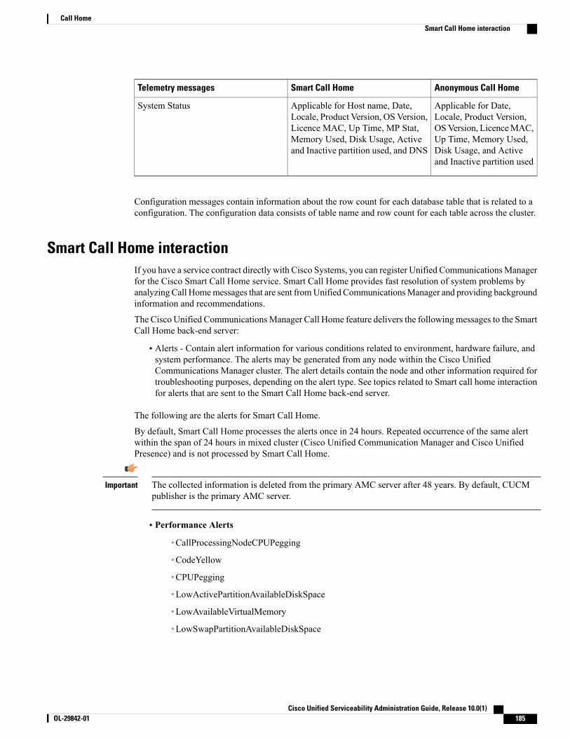
Anonymous Call HomeSmart Call HomeTelemetry messages
Applicable for Date,Locale, Product Version,OSVersion, LicenceMAC,Up Time, Memory Used,Disk Usage, and Activeand Inactive partition used
Applicable for Host name, Date,Locale, Product Version, OS Version,Licence MAC, Up Time, MP Stat,Memory Used, Disk Usage, Activeand Inactive partition used, and DNS
System Status
Configuration messages contain information about the row count for each database table that is related to aconfiguration. The configuration data consists of table name and row count for each table across the cluster.
Smart Call Home interactionIf you have a service contract directly with Cisco Systems, you can register Unified CommunicationsManagerfor the Cisco Smart Call Home service. Smart Call Home provides fast resolution of system problems byanalyzing Call Homemessages that are sent fromUnified CommunicationsManager and providing backgroundinformation and recommendations.
The Cisco Unified CommunicationsManager Call Home feature delivers the followingmessages to the SmartCall Home back-end server:
• Alerts - Contain alert information for various conditions related to environment, hardware failure, andsystem performance. The alerts may be generated from any node within the Cisco UnifiedCommunications Manager cluster. The alert details contain the node and other information required fortroubleshooting purposes, depending on the alert type. See topics related to Smart call home interactionfor alerts that are sent to the Smart Call Home back-end server.
The following are the alerts for Smart Call Home.
By default, Smart Call Home processes the alerts once in 24 hours. Repeated occurrence of the same alertwithin the span of 24 hours in mixed cluster (Cisco Unified Communication Manager and Cisco UnifiedPresence) and is not processed by Smart Call Home.
The collected information is deleted from the primary AMC server after 48 years. By default, CUCMpublisher is the primary AMC server.
Important
• Performance Alerts
◦CallProcessingNodeCPUPegging
◦CodeYellow
◦CPUPegging
◦LowActivePartitionAvailableDiskSpace
◦LowAvailableVirtualMemory
◦LowSwapPartitionAvailableDiskSpace
Cisco Unified Serviceability Administration Guide, Release 10.0(1) OL-29842-01 185
Call HomeSmart Call Home interaction

• Database - Related Alerts
◦DBReplicationFailure
• Failed Calls Alerts
◦MediaListExhausted
◦RouteListExhausted
• Crash - Related Alerts
◦Coredumpfilefound
◦CriticalServiceDown
The configuration, inventory, and telemetry messages are sent periodically (first day of every month) to theCall Home back-end. The information in these messages enables TAC to provide timely and proactive serviceto help customers manage and maintain their network.
Related Topics
Smart Call Home interaction, on page 185
Pre-requisites for Call HomeTo support the Cisco Unified Communications Manager Call Home service, you require the following:
• A Cisco.com user ID associated with a corresponding Cisco Unified Communications Manager servicecontract.
• It is highly recommended that both the Domain Name System (DNS) and SimpleMail Transfer Protocol(SMTP) servers are setup for the Cisco Unified Communications Manager Call Home feature.
◦DNS setup is required to send the Call Home messages using Secure Web (HTTPS).
◦SMTP setup is required to send the Call Home messages to Cisco TAC or to send a copy of themessages to a list of recipients through email.
Access Call HomeTo access Unified Communications Manager Call Home, go to Cisco Unified Serviceability Administrationand choose CallHome (Cisco Unified Serviceability > CallHome > Call Home Configuration).
Call Home settingsThe following table lists the default Cisco Unified Communications Manager Call Home settings.
Cisco Unified Serviceability Administration Guide, Release 10.0(1)186 OL-29842-01
Call HomePre-requisites for Call Home

Table 69: Default Call Home Settings
DefaultParameter
EnabledCall Home
Secure Web (HTTPS)Send Data to Cisco Technical Assistance Center(TAC) using
If default Smart Call Home configuration is changed during installation, then the same settings reflect in theCall Home user interface.
You must need to have a SMTP setup if you choose Email as the transport method and SMTP setup isnot a required for Secure Web (HTTPS) option.
Note
Call Home ConfigurationIn Cisco Unified Serviceability, choose Call Home > Call Home Configuration.
The Call Home Configuration window appears.
You can also configure the Cisco Smart Call Home while installing the Cisco Unified CommunicationsManager.
Note
The Smart Call Home feature is enabled if you configure Smart Call Home option during installation. If youselect None, a reminder message is displayed, when you log in to Cisco Unified Communications ManagerAdministration. Instructions to configure Smart Call Home or disable the reminder using Cisco UnifiedServiceability is provided.
The following table describes the settings to configure the Cisco Unified Communications Manager CallHome.
Table 70: Cisco Unified Communications Manager Call Home Configuration Settings
DescriptionField Name
Displays the date and time of the last Call Home messages that weresent and the next message that is scheduled.
Call Home Message Schedule
Cisco Unified Serviceability Administration Guide, Release 10.0(1) OL-29842-01 187
Call HomeCall Home Configuration

DescriptionField Name
From the drop-down list, select one of the following options:
• None:Select this option if you want to enable or disable the Call Home.A reminder message appears Smart Call Home is notconfigured. To configure Smart Call Home ordisable the reminder, please go to CiscoUnified Serviceability > Call Home or clickhere on the administrator page.
• Disabled: Select this option if you want to disable Call Home.
• Enabled (Smart Call Home): This option is enabled, if you haveselected Smart Call Home during installation. When you selectthis option, all the fields under Customer Contact Details areenabled. With the same configuration, the options in Send Dataare also enabled.
• Enabled (Anonymous Call Home): Select this option if you wantto use Call Home in anonymous mode. When you select thisoption, all the fields underCustomer Contact Details is disabled.With the same configuration, the Send a copy to the followingemail addresses (separate multiple addresses with comma) fieldin Send Data is enabled, and Include Trace logs and DiagnosticsInformation is disabled on Call Home page.
If you enable Anonymous Call Home, the server sendsusage statistics to Cisco systems from the server. Thisinformation helps Cisco to understand user experienceabout the product and to drive product direction.
Note
Call Home*
Customer Contact Details
Enter the contact email address of the customer. This is a mandatoryfield.
Email Address*
(Optional) Enter the name of the company. You can enter up to 255characters.
Company
(Optional) Enter the contact name of the customer. You can enter upto 128 characters.
The contact name can contain alphanumeric characters and some specialcharacters like dot (.), underscore (_) and, hyphen (-).
Contact Name
(Optional) Enter the address of the customer. You can enter up to 1024characters.
Address
(Optional) Enter the phone number of the customer.Phone
Send Data
Cisco Unified Serviceability Administration Guide, Release 10.0(1)188 OL-29842-01
Call HomeCall Home Configuration

DescriptionField Name
This is a Mandatory field. From the drop-down list, select one of thefollowing options to send Call Home messages to Cisco TAC:
• SecureWeb (HTTPS): Select this option if you want to send thedata to Cisco TAC using secure web.
• Email: Select this option if you want to send the data to CiscoTAC using email. For email, the SMTP server must be configured.You can see the Host name or IP address of the SMTP server thatis configured.
A warning message displays if you have not configuredthe SMTP server.
Note
• Secure Web (HTTPS) through Proxy: Select this option if youwant to send the data to Cisco TAC through proxy. Currently, wedo not support Authentication at the proxy level. The followingfields appear on configuring this option:
◦HTTPS Proxy IP/Hostname*: Enter the proxyIP/Hostname.
◦HTTPS Proxy Port*: Enter the proxy port number tocommunicate.
Send Data to Cisco TechnicalAssistance Center (TAC) using
Check this check box to send a copy of the Call Home messages to thespecified email addresses. You can enter up to a maximum of 1024characters.
Send a copy to the following emailaddresses (separate multipleaddresses with comma)
Check this check box to activate the Cisco Unified CommunicationsManager to collect logs and diagnostics information.
This option is active only if the Smart Call Home is enabled.
The message contains diagnostic information collected at thetime of alert along with trace message. If the trace size is lessthan 3 MB, then the traces will be encoded and sent as part ofalert message and if the traces are more than 3 MB then thepath of the trace location is displayed in the alert message.
Note
Include Trace logs and DiagnosticInformation
Saves your Call Home configuration.
After you save your Call Home Configuration, an End UserLicense Agreement (EULA) message appears. If you areconfiguring for the first time, you must accept the licenseagreement.
Note
To deactivate the Call Home service that you activated, selectthe Disabled option from the drop-down list and click Save.
Tip
Save
Resets to last saved configuration.Reset
Cisco Unified Serviceability Administration Guide, Release 10.0(1) OL-29842-01 189
Call HomeCall Home Configuration

DescriptionField Name
Saves and sends the Call Home messages.
A message appears Call Home Configuration saved and allCall Home Messages sent successfully if the messages aresent successfully.
Note
Save and Call Home Now
LimitationsThe following limitations apply when Cisco Unified Communications Manager or Cisco Unified Presenceserver is down or unreachable:
• Smart Call Home fails to capture the date and time of the last Call Home messages sent and the nextmessage scheduled, until the server is reachable.
• Smart Call Home does not send the Call Home messages, until the server is reachable.
• Smart Call Home will be unable to capture license information in the inventory mail when the publisheris down.
The following limitations are due to Alert Manager and Collector (AMC):
• If an alert occurs on node A and the primary AMC server (by default, publisher) is restarted, and if thesame alert occurs within a span of 24 hours on the same node, Smart Call Home resends the alert datafrom node A. Smart Call Home cannot recognize the alert that has already occurred because the primaryAMC was restarted.
• If an alert occurs on node A and if you change the primary AMC server to another node, and if the samealert occurs within a span of 24 hours on the same node, Smart Call Home recognizes it as a fresh alerton node A and sends the alert data.
• The traces that are collected on the primary AMC server may reside on the primary AMC server for amaximum of 60 hours in few scenarios.
The following are the limitations in the mixed cluster (Cisco Unified Communications Manager and IM andPresence) scenario:
• Alerts like CallProcessingNodeCpuPegging,Media List Exhausted, Route List Exhausted are notapplicable to IM and Presence.
• If the user changes primary AMC server to IM and Presence, then Smart Call Home cannot generateCuster Overview reports forMedia List Exhausted and Route List Exhausted.
• If the user changes primary AMC server to IM and Presence, then Smart Call Home cannot generateOverview reports for DB Replication alert.
References for Call HomeFor more information about Smart Call Home, refer the following URL:
• Smart Call Home Service Introduction
Cisco Unified Serviceability Administration Guide, Release 10.0(1)190 OL-29842-01
Call HomeLimitations

http://www.cisco.com/en/US/products/ps7334/serv_home.html
Cisco Unified Serviceability Administration Guide, Release 10.0(1) OL-29842-01 191
Call HomeReferences for Call Home

Cisco Unified Serviceability Administration Guide, Release 10.0(1)192 OL-29842-01
Call HomeReferences for Call Home
I N D E X
A
A Cisco DB service 74accessing 5
web interface 5alarm definitions 15, 25, 26, 27
CallManager Alarm catalog 26overview 15System Alarm Catalog 25, 27
alarms 13, 14, 15, 16, 17, 19, 20, 25, 26, 27CallManager Alarm Catalog 26Cisco Syslog Agent Enterprise Parameters 17configuration checklist 16configuration overview 14configuration settings 20configuring 17, 19definitions 15destinations 20event level settings 20Event Viewer 20NT Event Viewer 20overview 13SDI trace library 20SDL trace library (CUM and UCMBE only) 20service groups for 19Syslog 20System Alarm Catalog 25, 27updating 17, 19viewing information 16
alert summary report 107audit log 119, 124
configuration settings (table) 124configuring 124understanding 119
B
browser support 3
C
call activities report 103call home 181, 187
configuring 187understanding 181
CallManager Alarm Catalog 26CDR general parameter 115Cisco AMC Service 72Cisco CallManager Admin service 80Cisco CallManager Cisco IP Phone Services 77Cisco CallManager Personal Directory service 77Cisco CallManager service 64Cisco CallManager Serviceability service 73Cisco CAR Scheduler service 79Cisco CAR Web Service 70Cisco CDP Agent service 74Cisco CDP service 73Cisco CDR Agent service 79Cisco Certificate Authority Proxy Function (CAPF) service 70Cisco Certificate Expiry Monitor service 74Cisco CTIManager service 64Cisco CTL Provider service 70Cisco Database Layer Monitor service 76Cisco DB service 74Cisco DHCP Monitor service 64Cisco Dialer Analyzer service 64Cisco DirSync service 71Cisco DRF Local 73Cisco DRF Master 73Cisco Extended Functions service 71Cisco Extension Mobility Application 77Cisco Extension Mobility service 64Cisco IP Manager Assistant Service 69Cisco IP Voice Media Streaming App service 64Cisco License Manager service 74Cisco Log Partition Monitoring Tool service 72Cisco Messaging Interface service 64Cisco RIS Data Collector service 72Cisco RTMT Reporter Servlet 72Cisco SOAP - CDRonDemand Service 70Cisco SOAP-Log Collection APIs 76
Cisco Unified Serviceability Administration Guide, Release 10.0(1) OL-29842-01 IN-1

Cisco SOAP-Performance Monitoring APIs service 76Cisco SOAP-Real-Time Service APIs service 76Cisco Syslog Agent service 74Cisco TFTP service 64Cisco Tomcat service 74Cisco Tomcat Stats Servlet 72Cisco Trace Collection Service 73Cisco Trace Collection Servlet 73Cisco Trust Verification Service 75Cisco Unified Mobile Voice Access Service 64Cisco WebDialer Web Service 69CISCO-CCM-CAPABILITY MIB 137CISCO-CCM-MIB 137, 178
dynamic tables 137static tables 137trap parameters 178
configuring 178Cisco-CDP-MIB 137CISCO-SYSLOG-MIB 137, 177
trap parameters 177configuring 177
CISCO-UNITY-MIB 137, 179objects 137trap parameters 179
configuring 179CLI 91
starting services 91stopping services 91
cluster 82service activation recommendations 82
community strings 154, 157, 158, 159, 160configuration settings 159configuring 158deleting 160finding 157
Control Center 81, 90feature services 81network services 81overview 81starting services 81, 90stopping services 81, 90viewing service status 81viewing status 90
D
debug trace levels 40, 41, 42, 43, 44, 46, 47, 48, 49, 50, 53, 55Cisco CallManager 43, 44
SDI fields 43SDL fields 44
Cisco CTIManager 46SDI fields 46
debug trace levels (continued)Cisco CTIManager (continued)
SDL fields 46Cisco Extended Functions fields 47Cisco Extension Mobility fields 48Cisco IP Manager Assistant fields 49Cisco IP Voice Media Streaming Application fields 49Cisco Web Dialer Web Service fields 50Database Layer Monitor fields 41, 53RIS Data Collector fields 42, 55service settings 40servlet settings 40TFTP fields 50
device name based trace monitoring 32device statistics report 94disk allocation 115document xiv
product security overview xiv
E
event levels for alarms 20exclude end point alarms 20
F
feature services 81, 89, 90activating 89configuration checklist 81deactivating 89starting 90stopping 90viewing status 90
G
general parameter settings 115
H
Host Resources Agent service 74HOST-RESOURCES MIB 137HTTPS 7, 8
overview (IE and Netscape) 7saving certificate to trusted folder (IE) 8
Cisco Unified Serviceability Administration Guide, Release 10.0(1)IN-2 OL-29842-01
Index

I
informs 154, 161, 162, 163, 164, 168, 169, 170, 171configuration parameters 154configuration settings 163, 170configuring 162, 169deleting 164, 171finding 161, 168overview 154
M
Management Information Base (MIB) 137CISCO-CCM-CAPABILITY MIB 137CISCO-CCM-MIB 137
dynamic tables 137static tables 137
Cisco-CDP-MIB 137CISCO-SYSLOG-MIB 137CISCO-UNITY-MIB 137
objects 137HOST-RESOURCES MIB 137MIB-II 137overview 137SYSAPPL-MIB 137
MIB-II 137MIB2 Agent service 74MIB2 system group 172
configuring 172
N
Network Agent Adaptor service 74network services 72, 90
Control Center 72overview 72starting 72, 90stopping 72, 90viewing status 72, 90
notification destination (V1/V2) 161, 162, 163, 164configuration settings 163configuring 162deleting 164finding 161
notification destination (V3) 168, 169, 170, 171configuration settings 170configuring 169deleting 171finding 168
NT Event Viewer 20
O
output settings for trace 57overview 3, 5, 6, 7, 13, 15, 29, 30, 31, 72, 93, 135, 136, 137, 154
accessing interface 6accessing web interface 5alarm definitions 15alarms 13browser support 3HTTPS 7informs 154MIBs 137network services 72serviceability archive reports 93serviceability reports archive 93SNMP 135, 136trace 29trace collection 31traps 154troubleshooting trace settings 30
P
performance protection report 109product security overview xiv
R
Real-Time Monitoring Tool 72, 94, 97, 100, 103, 107, 109alert summary report 107call activities report 103device statistics report 94performance protection report 109server statistics report 97service 72
Cisco AMC Service 72Cisco CallManager Serviceability RTMT 72Cisco Log Partition Monitoring Tool 72Cisco RIS Data Collector 72Cisco RTMT Reporter Servlet 72Cisco Tomcat Stats Servlet 72
service statistics report 100serviceability reports archive 94
service parameters 94report 94, 97, 100, 103, 107, 109
alert summary 107call activities 103device statistics 94performance protection 109server statistics 97service statistics 100
Cisco Unified Serviceability Administration Guide, Release 10.0(1) OL-29842-01 IN-3
Index
S
SDL configuration 44, 46characteristics 44, 46
Cisco CallManager service 44Cisco CTIManager service 46
filter settings 44, 46Cisco CallManager service 44Cisco CTIManager 46
security 8HTTPS for IE 7 8
server statistics report 97service 17, 19, 32, 40, 64, 69, 70, 71, 72, 73, 74, 75, 76, 77, 79, 80, 81, 89,
90A Cisco DB 74activating 89activating trace 32Cisco AMC Service 72Cisco CallManager 64Cisco CallManager Admin 80Cisco CallManager Cisco IP Phone Services 77Cisco CallManager Personal Directory 77Cisco CallManager Serviceability 73Cisco CallManager Serviceability RTMT 72Cisco CAR Scheduler 79Cisco CAR Web Service 70Cisco CDP 73Cisco CDP Agent 74Cisco CDR Agent 79Cisco Certificate Authority Proxy Function (CAPF) 70Cisco Certificate Expiry Monitor 74Cisco CTIManager 64Cisco CTL Provider 70Cisco Database Layer Monitor 76Cisco DHCP Monitor Service 64Cisco Dialed Number Analyzer 64Cisco Dialed Number Analyzer Server 64Cisco DirSync 71Cisco DRF Local 73Cisco DRF Master 73Cisco Extended Functions 71Cisco Extension Mobility 64Cisco Extension Mobility Application 77Cisco IP Manager Assistant 69Cisco IP Voice Media Streaming App 64Cisco License Manager 74Cisco Log Partition Monitoring Tool 72Cisco Messaging Interface 64Cisco RIS Data Collector 72Cisco RTMT Reporter Servlet 72Cisco SOAP - CDRonDemand Service 70Cisco SOAP-Log Collection APIs 76Cisco SOAP-Performance Monitoring APIs 76Cisco SOAP-Real-Time Service APIs 76
service (continued)Cisco Syslog Agent 74Cisco TFTP 64Cisco Tomcat 74Cisco Tomcat Stats Servlet 72Cisco Trace Collection Service 73Cisco Trace Collection Servlet 73Cisco Trust Verification Service 75Cisco Unified Mobile Voice Access Service 64Cisco WebDialer Web Service 69configuration checklist 81configuring alarms for 17, 19Control Center overview 81deactivating 89debug trace levels 40Host Resources Agent 74MIB2 Agent 74Native Agent Adaptor 74network services 72SNMP Master Agent 74starting 90starting services 81stopping 90stopping services 81System Application Agent 74viewing service status 81viewing status 90
service activation 82, 89activating 89deactivating 89recommendations for a cluster 82
service groups 19, 34alarms 19for trace 34
service statistics report 100serviceability 6
accessing 6serviceability reports archive 93, 94, 97, 100, 103, 107, 109, 110, 111
alert summary report 107call activities report 103configuration checklist 110configuring 111device statistic report 94overview 93performance protection report 109server statistic report 97service parameters 94service statistics report 100
services 41trace field descriptions 41
servlet 40debug trace levels 40
Cisco Unified Serviceability Administration Guide, Release 10.0(1)IN-4 OL-29842-01
Index
SNMP 74, 135, 136, 137, 151, 152, 153, 154, 157, 158, 159, 160, 161, 162, 163, 164, 165, 166, 168, 169, 170, 171, 172, 177, 178, 179
basics 136CISCO-CCM-MIB trap parameters 178
configuring 178CISCO-SYSLOG-MIB trap parameters 177
configuring 177CISCO-UNITY-MIB trap parameters 179
configuring 179community strings 154, 157, 158, 159, 160
configuration settings 159configuring 158deleting 160finding 157
configuration checklist 151configuration requirements 152informs 154, 161, 162, 163, 164, 168, 169, 170, 171
configuration parameters 154configuration settings 163, 170configuring 162, 169deleting 164, 171finding 161, 168overview 154
MIB 137MIB2 system group 172
configuring 172notification destination (V1/V2) 161, 162, 163, 164
configuration settings 163configuring 162deleting 164finding 161
notification destination (V3) 168, 169, 170, 171configuration settings 170configuring 169deleting 171finding 168
overview 135remote monitoring with 135service 74
Cisco CDP Agent 74Cisco Syslog Agent 74Host Resources Agent 74MIB2 Agent 74Network Agent Adaptor 74SNMP Master Agent 74System Application Agent 74
services 153SNMPv1 152SNMPv2c 153SNMPv3 153trace configuration 157traps 154, 161, 162, 163, 164, 168, 169, 170, 171
configuration parameters 154configuration settings 163, 170
SNMP (continued)traps (continued)
configuring 162, 169deleting 164, 171finding 161, 168overview 154
troubleshooting 151user 165, 166, 168
configuration settings 166configuring 165deleting 168finding 165
users 154SNMP Master Agent service 74SOAP 70, 76
service 70, 76Cisco SOAP - CDRonDemand Service 70Cisco SOAP-Log Collection APIs 76Cisco SOAP-Performance Monitoring APIs 76Cisco SOAP-Real-Time Service APIs 76
SYSAPPL-MIB 137System Alarm Catalog 25, 27System Application Agent service 74
T
trace 29, 30, 31, 32, 34, 40, 41, 42, 43, 44, 46, 47, 48, 49, 50, 53, 55, 57, 157called party trace 31Cisco CallManager service 43, 44
SDI trace fields 43SDL trace fields 44
Cisco CTIManager service 46SDI trace fields 46SDL trace fields 46
Cisco Database Layer Monitor service 41, 53trace fields 41, 53
Cisco Extended Functions service 47trace fields 47
Cisco Extension Mobility service 48trace fields 48
Cisco IP Manager Assistant service 49trace fields 49
Cisco IP Voice Media Streaming App service 49trace fields 49
Cisco RIS Data Collector service 42, 55trace fields 42, 55
Cisco TFTP service 50trace fields 50
Cisco Web Dialer Web Service 50trace fields 50
collection 31configuration and collection checklist 31
Cisco Unified Serviceability Administration Guide, Release 10.0(1) OL-29842-01 IN-5
Index

trace (continued)configuration overview 30configuring 32debug trace levels for service 40debug trace levels for servlet 40device name based trace monitoring 32output settings 57overview 29recommendations for SNMP 157service groups for 34trace and log central 31trace field descriptions 41troubleshooting trace settings 30
trace collection 31traps 154, 161, 162, 163, 164, 168, 169, 170, 171
configuration parameters 154configuration settings 163, 170configuring 162, 169deleting 164, 171
traps (continued)finding 161, 168overview 154
troubleshooting 30trace settings 30
U
users (SNMP) 154, 165, 166, 168configuration settings 166configuring 165deleting 168finding 165
V
viewing alarm information 16
Cisco Unified Serviceability Administration Guide, Release 10.0(1)IN-6 OL-29842-01
Index