Embed Size (px)
Citation preview
© 2017 Cisco and/or its affiliates. All rights reserved. This document is Cisco Public Information. Page 1 of 27
Cisco Software-Defined Access Upgrade Guide
Upgrade Guide
© 2018 Cisco and/or its affiliates. All rights reserved. This document is Cisco Public Information. Page 2 of 27
Contents
Cisco SD-Access ..................................................................................................................................................... 3 Evolution of networking toward fabric ................................................................................................................... 3
Cisco SD-Access overview ..................................................................................................................................... 5
Upgrade considerations .......................................................................................................................................... 7 Network considerations ......................................................................................................................................... 7 Policy considerations ............................................................................................................................................ 8 Existing network design ........................................................................................................................................ 9
Upgrade .................................................................................................................................................................. 10 Reference network design for upgrade ............................................................................................................... 10 Use new IP subnets optimized for SD-Access .................................................................................................... 11 Connecting the first fabric border/control plane and fabric edge switch .............................................................. 11 Incremental approach ......................................................................................................................................... 12
Service interworking with SD-Access .................................................................................................................. 25
Summary ................................................................................................................................................................ 27
© 2018 Cisco and/or its affiliates. All rights reserved. This document is Cisco Public Information. Page 3 of 27
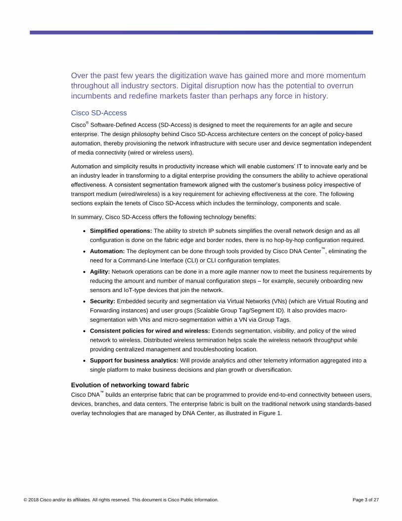
Over the past few years the digitization wave has gained more and more momentum
throughout all industry sectors. Digital disruption now has the potential to overrun
incumbents and redefine markets faster than perhaps any force in history.
Cisco SD-Access
Cisco® Software-Defined Access (SD-Access) is designed to meet the requirements for an agile and secure
enterprise. The design philosophy behind Cisco SD-Access architecture centers on the concept of policy-based
automation, thereby provisioning the network infrastructure with secure user and device segmentation independent
of media connectivity (wired or wireless users).
Automation and simplicity results in productivity increase which will enable customers’ IT to innovate early and be
an industry leader in transforming to a digital enterprise providing the consumers the ability to achieve operational
effectiveness. A consistent segmentation framework aligned with the customer’s business policy irrespective of
transport medium (wired/wireless) is a key requirement for achieving effectiveness at the core. The following
sections explain the tenets of Cisco SD-Access which includes the terminology, components and scale.
In summary, Cisco SD-Access offers the following technology benefits:
● Simplified operations: The ability to stretch IP subnets simplifies the overall network design and as all
configuration is done on the fabric edge and border nodes, there is no hop-by-hop configuration required.
● Automation: The deployment can be done through tools provided by Cisco DNA Center™
, eliminating the
need for a Command-Line Interface (CLI) or CLI configuration templates.
● Agility: Network operations can be done in a more agile manner now to meet the business requirements by
reducing the amount and number of manual configuration steps – for example, securely onboarding new
sensors and IoT-type devices that join the network.
● Security: Embedded security and segmentation via Virtual Networks (VNs) (which are Virtual Routing and
Forwarding instances) and user groups (Scalable Group Tag/Segment ID). It also provides macro-
segmentation with VNs and micro-segmentation within a VN via Group Tags.
● Consistent policies for wired and wireless: Extends segmentation, visibility, and policy of the wired
network to wireless. Distributed wireless termination helps scale the wireless network throughput while
providing centralized management and troubleshooting location.
● Support for business analytics: Will provide analytics and other telemetry information aggregated into a
single platform to make business decisions and plan growth or diversification.
Evolution of networking toward fabric
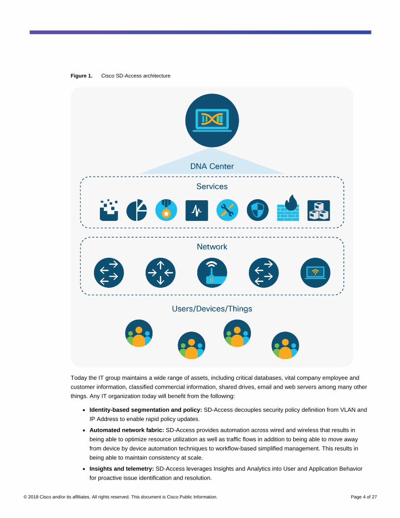
Cisco DNA™
builds an enterprise fabric that can be programmed to provide end-to-end connectivity between users,
devices, branches, and data centers. The enterprise fabric is built on the traditional network using standards-based
overlay technologies that are managed by DNA Center, as illustrated in Figure 1.
© 2018 Cisco and/or its affiliates. All rights reserved. This document is Cisco Public Information. Page 4 of 27
Figure 1. Cisco SD-Access architecture
Today the IT group maintains a wide range of assets, including critical databases, vital company employee and
customer information, classified commercial information, shared drives, email and web servers among many other
things. Any IT organization today will benefit from the following:
● Identity-based segmentation and policy: SD-Access decouples security policy definition from VLAN and
IP Address to enable rapid policy updates.
● Automated network fabric: SD-Access provides automation across wired and wireless that results in
being able to optimize resource utilization as well as traffic flows in addition to being able to move away
from device by device automation techniques to workflow-based simplified management. This results in
being able to maintain consistency at scale.
● Insights and telemetry: SD-Access leverages Insights and Analytics into User and Application Behavior
for proactive issue identification and resolution.
© 2018 Cisco and/or its affiliates. All rights reserved. This document is Cisco Public Information. Page 5 of 27
● Policy convergence between wired and wireless
● Flexible authentication options for user, device, and things including 802.1X, Active Directory, and static
authentication.
● Better positioned for increased cloud usage via WAN and internet; acceleration/optimization for cloud
Cisco SD-Access overview
The Cisco SD-Access fabric leverages an efficient, and scalable transport network built according to Cisco best
practices and recommendations. It provides any switch to any switch connectivity via standards based stateless
tunnels. LISP and VXLAN are the underlying technologies used to build the Cisco SD-Access fabric, however
these technologies are completely abstracted from the end-user.
Note: As this fabric is built on top a traditional network, it is normally referred to as an overlay network and the
traditional network is referred as an underlay network.
The networking approach used to build the Cisco SD-Access fabric consists of a prescriptive physical underlay and
a programmable overlay with segmentation constructs such as Virtual Network (VN) and groups. This new
approach enables enterprise networks to transition from traditional VLAN-centric design architecture to a new user
group-centric design architecture.
The following table defines the components used in the Cisco SD-Access fabric.
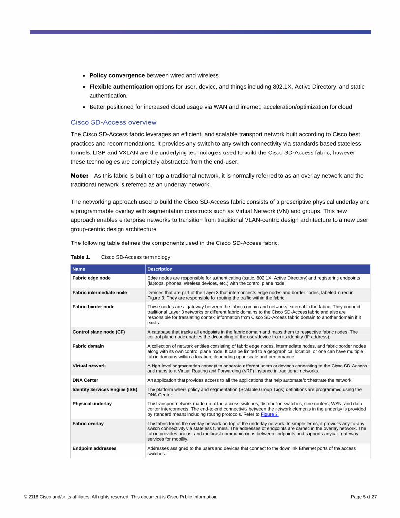
Table 1. Cisco SD-Access terminology
Name Description
Fabric edge node Edge nodes are responsible for authenticating (static, 802.1X, Active Directory) and registering endpoints (laptops, phones, wireless devices, etc.) with the control plane node.
Fabric intermediate node Devices that are part of the Layer 3 that interconnects edge nodes and border nodes, labeled in red in Figure 3. They are responsible for routing the traffic within the fabric.
Fabric border node These nodes are a gateway between the fabric domain and networks external to the fabric. They connect traditional Layer 3 networks or different fabric domains to the Cisco SD-Access fabric and also are responsible for translating context information from Cisco SD-Access fabric domain to another domain if it exists.
Control plane node (CP) A database that tracks all endpoints in the fabric domain and maps them to respective fabric nodes. The control plane node enables the decoupling of the user/device from its identity (IP address).
Fabric domain A collection of network entities consisting of fabric edge nodes, intermediate nodes, and fabric border nodes along with its own control plane node. It can be limited to a geographical location, or one can have multiple fabric domains within a location, depending upon scale and performance.
Virtual network A high-level segmentation concept to separate different users or devices connecting to the Cisco SD-Access and maps to a Virtual Routing and Forwarding (VRF) instance in traditional networks.
DNA Center An application that provides access to all the applications that help automate/orchestrate the network.
Identity Services Engine (ISE) The platform where policy and segmentation (Scalable Group Tags) definitions are programmed using the DNA Center.
Physical underlay The transport network made up of the access switches, distribution switches, core routers, WAN, and data center interconnects. The end-to-end connectivity between the network elements in the underlay is provided by standard means including routing protocols. Refer to Figure 2.
Fabric overlay The fabric forms the overlay network on top of the underlay network. In simple terms, it provides any-to-any switch connectivity via stateless tunnels. The addresses of endpoints are carried in the overlay network. The fabric provides unicast and multicast communications between endpoints and supports anycast gateway services for mobility.
Endpoint addresses Addresses assigned to the users and devices that connect to the downlink Ethernet ports of the access switches.
© 2018 Cisco and/or its affiliates. All rights reserved. This document is Cisco Public Information. Page 6 of 27
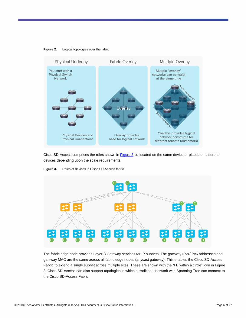
Figure 2. Logical topologies over the fabric
Cisco SD-Access comprises the roles shown in Figure 3 co-located on the same device or placed on different
devices depending upon the scale requirements.
Figure 3. Roles of devices in Cisco SD-Access fabric
The fabric edge node provides Layer-3 Gateway services for IP subnets. The gateway IPv4/IPv6 addresses and
gateway MAC are the same across all fabric edge nodes (anycast gateway). This enables the Cisco SD-Access
Fabric to extend a single subnet across multiple sites. These are shown with the “FE within a circle” icon in Figure
3. Cisco SD-Access can also support topologies in which a traditional network with Spanning Tree can connect to
the Cisco SD-Access Fabric.
© 2018 Cisco and/or its affiliates. All rights reserved. This document is Cisco Public Information. Page 7 of 27
Upgrade considerations
These are considerations that need to be taken into account before beginning the upgrade of the existing network
to Cisco SD-Access. These are categorized as follows:
● Network considerations: MTU, network topology, IP addressing for underlay and overlay, and location of
shared services.
● Policy considerations: Existing policy definition and enforcement points, virtual network and Scalable Group
Tags
● Hardware platform considerations: Switches, routers, WLCs, and access points that support SD-Access
● Software platform considerations: DNA Center, Identity Services Engine (ISE), Network Data Platform
(NDP)
● Scale of deployment considerations: Scale of hardware platforms with respect to the role they play in the
SD-Access solution architecture
● Existing network design: Layer 2 Access or Routed access
Network considerations
Maximum Transmission Unit (MTU)
MTU is defined as the largest network protocol data unit that can be transmitted in a single transaction. The higher
the MTU the more efficient the network. The VXLAN encapsulation adds 50 bytes to the original packet. This can
cause MTU to go above 1500 bytes for certain applications for example, wireless is deployed with SD-Access,
where the additional CAPWAP overhead needs to be considered. In general, increasing the MTU to 9100s bytes
on interfaces across all switches, and routers in the fabric domain (underlay and overlay) is recommended to cover
most cases to prevent fragmentation.
Network topology
SD-Access fabric supports the traditional hierarchical networks as well as arbitrarily designed networks such as
ring topology, or daisy-chained topologies. Note: A network designed with the Cisco Validated Design (CVD)
guidelines, will have less considerations (steps) when upgrading compared to arbitrarily designed networks that
have the inherent complexities by the very nature of the design. Since fabric underlay topologies are based on a
routed access design, if the existing network is routed access, it lends itself to easier upgrade to SD-Access.
IP addressing for underlay/overlay
Existing campus networks are flat networks and do not have any concept of underlay and overlay. All the IP
address schema is flat with no distinction between intra-network prefixes and endpoint network prefixes. SD-
Access by its very nature, contains overlay and underlay to differentiate between the two spaces. It is
recommended that two distinct IP ranges be selected for the endpoint network prefixes (overlay) and intra-network
prefixes (underlay). The advantages are two-fold. The first is to enable summarization of the IP space when
advertising in routing considerations. The second is because of its distinct nature, troubleshooting is easier since
one has a clear understanding of which IP space is being looked at, at that moment. For example, the overlay
could be a 10.0.0.0/8 space, and the underlay range could be a 172.16.0.0/16 space.
© 2018 Cisco and/or its affiliates. All rights reserved. This document is Cisco Public Information. Page 8 of 27
Location of shared services
Shared services in the network include services like DHCP, DNS, IP Address Management, NTP, NetFlow
collector, syslog, Network Management Systems (NMS), and others. Traditionally all these services lie outside the
campus or branch network in a data center. Some network designs do have some or all of these services in the
campus or branch connected to either a core or a distribution layer. Additionally, the shared services are normally
in the Global Routing Table (GRT), although in some deployments, they might lie in a separate Virtual Routing and
Forwarding (VRF) context. It is essential that network devices and endpoints have access to the basic services
such as DHCP and DNS in order to connect to the network and forward traffic. The steps toward upgrading to SD-
Access differ depending upon the physical location as well as the presence in either GRT or VRF of the shared
services in the existing network.
Application of features at the distribution layer
In a Layer 2 access design, in most cases, features like (IP ACLs, NetFlow, QoS classification, marking and
policing, and others) are configured at the distribution layer switches. Since SD-Access is a fabric solution, the
incoming packets from the endpoints are encapsulated in the fabric data plane by the fabric edge, making the
distribution layer switches act as intermediate nodes switching IP packets back and forth between fabric edge
(access layer) and upstream switches in the network. Due to the encapsulation at the fabric edge itself, the IP
classification that the features were based on at the distribution is not available and hence the consideration of
moving these features now to the access layer switches in the network.
Routing between VRF and underlay to external network
The Routing Locator addresses (typically Loopback0) and underlay physical connectivity address space is in the
Global routing table. The endpoint IP space will typically be in VRFs if not the default VRF. The network devices
will still be reachable to the infrastructure/network management stations via the RLOC space in the global routing
table.
Policy considerations
A mind shift is needed when Scalable Group Tag (SGT) enforcement is considered because the enforcement is not
based on static IP ACLs, but rather on dynamic downloaded SG ACLs, which are more secure and allow for an
abstraction from the networking constructs (IP address, VLANs, etc.) that simplify the policy deployment.
802.1X implementation further strengthens the onboarding of endpoints onto the network since network
connections are now authenticated and/or profiled and placed in the right area in the network. How the users and
things on the network should be isolated from each other is another consideration that the network administrator
should work along with the security administrator of the network. SD-Access provides dual level of segmentation
within the network. With the deployment of VRFs (Virtual Routing and Forwarding) or VNs (Virtual Networks)
providing the classic path isolation among endpoints and SG ACLs enforcement providing differentiated access-
control within the VN, it is imperative that the network and security administrators work together to form a
segmentation and access-control policy that will be applied consistently in the network.
© 2018 Cisco and/or its affiliates. All rights reserved. This document is Cisco Public Information. Page 9 of 27
Hardware platform considerations
Table 2. Cisco SD-Access hardware requirements
Name Description
Switching Cisco Catalyst® 3850/3650 Series Switches
Cisco Catalyst 4500E SUP8-E Supervisors
Cisco Catalyst 9000 family switches (9300, 9400, 9500 Series)
Cisco Catalyst 6500/6800 Series with SUP2T and SUP6T with 6800 series line cards
Cisco Catalyst 6840 and 6880 Series Switches
Cisco Nexus® 7700 (with M3 series line cards)
Routing ISR 4400 Series routers
ASR 1000X/HX Series routers
Wireless WLC 3504, 5520, and 8540
802.11ac Wave 2 APs and later (Wave 1 APs with restrictions)
Software platform considerations
Based upon deployment size, scalability and redundancy, the software functions can be run on top of individual
Virtual Machines (VMs) or dedicated appliances for the DNA Center, ISE (Identity Services Engine).
The current software requirements to implement Cisco SD-Access architecture are listed below
Table 3. Cisco SD-Access software requirements
Name Description
Software components DNA Center 1.1.3
Identity Service Engine (ISE) 2.3 Patch 1
Cisco SD-Access scaling considerations
The Cisco SD-Access fabric scaling depends on the number of hosts and devices in a single site or across multiple
sites. In the first release, DNA Center will support 1000 network devices as fabric nodes (that includes fabric edge,
fabric border, and fabric control plane nodes and wireless LAN controllers, excluding access points) and 20,000
endpoints per fabric domain. A total of 10 fabric domains are supported with DNA Center 1.1. Geographical
locations that are in close proximity from a latency and performance standpoint can be controlled by a single DNA
Center instance. It is recommended that DNA Center be co-located near other software control plane entities such
as ISE administrative nodes to reduce latency for communications between them. This way there is one variable
which is latency due to the WAN infrastructure (links and speeds) and not a combination of both. The locations
might be in the data center or the main campus site, depending upon customer implementation.
It is recommended to run two control plane nodes per fabric domain for redundancy. For a given fabric domain, the
choice of platform will depend upon the number of host entries to be managed by the CP node. Hosting a single
CP node instance on a switch platform with active and standby supervisors or stack members provides additional
level of redundancy within a system. Hosting the other instance on another switch also provides an additional layer
of redundancy across systems. In the latter case, both control planes are active-active and all registrations are sent
to both control plane nodes independently. There is no synchronization of the database across two control plane
nodes.
Existing network design
There are generally two types of networks – branch and campus. Depending on their size, they can be either two
more tier. Sometimes the topology is constrained by the physical factors like space, and could lead to a daisy-
© 2018 Cisco and/or its affiliates. All rights reserved. This document is Cisco Public Information. Page 10 of 27
chained or a ring topology. A network topology designed using guidelines from the Cisco Validated Design is
recommended. Whatever the topology physical design, it can be upgraded to SD-Access – it is just that additional
time and consideration should be given for the deviations from the Cisco Validated Design. There are two ways of
approaching an upgrade as well.
‘Parallel Install’ is erecting a new network parallel to the existing network. Parallel Install needs prerequisites like
space, power, cooling, and cabling to be available in order to satisfy parallel live connections. This approach
makes the upgrade easier with the ability to revert to the existing network should the need arise, but it is also the
most expensive in the sense that there are two networks running live, consuming power and space over a period of
time while the upgrade is successfully completed.
Upgrading one switch at a time allows an incremental upgrade of certain areas of the network rather than
upgrading en masse. It is not dependent on factors like space, power, and cabling compared to the above
approach and is more reasonable from a cost perspective. Network administrators have the option of experiencing
how the new network will provide services and connections using a lot fewer network devices than the above
approach. This approach also provides an opportunity to build a small SD-Access deployment over the existing
network and test user scenarios in that small deployment.
Upgrade
Reference network design for upgrade
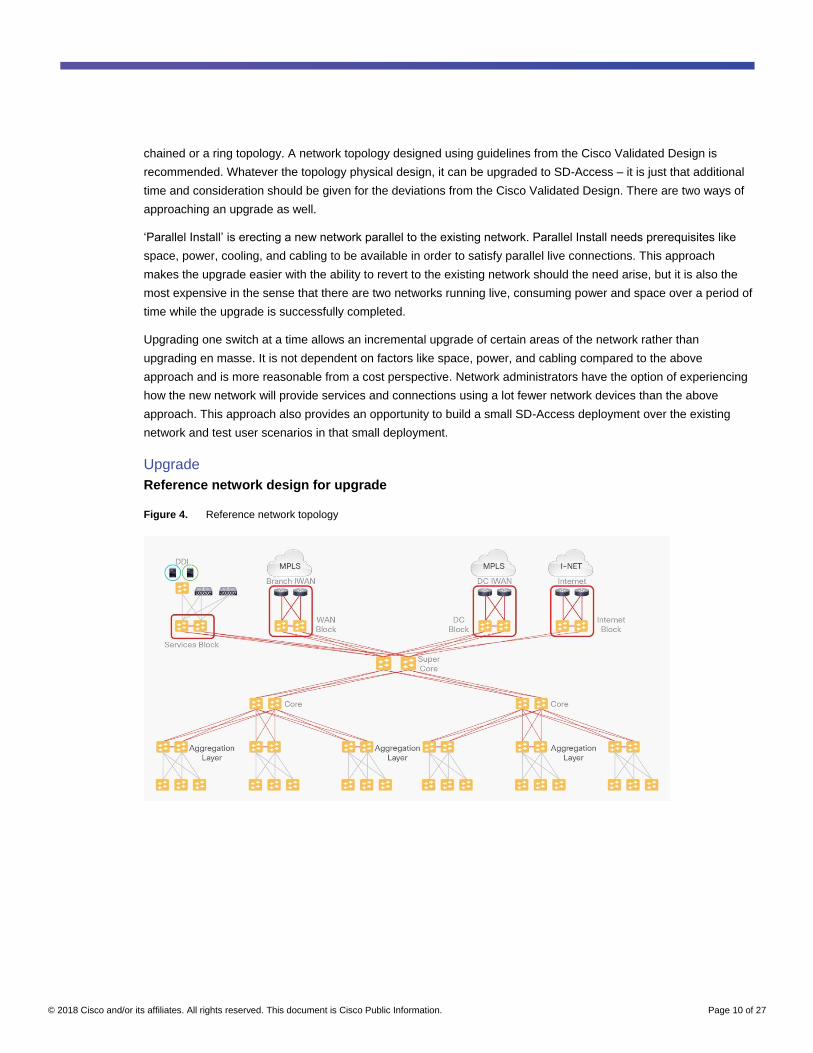
Figure 4. Reference network topology
© 2018 Cisco and/or its affiliates. All rights reserved. This document is Cisco Public Information. Page 11 of 27
Consider the above campus network. It is a multitiered network where endpoints connect into the network at the
access layer. This layer is aggregated into aggregation layer switches typically at the MDF (Main Distribution
Frame). Typically, depending upon density, a building can be thought of as an aggregation block. The access
network is a Layer 2 access design, and VLANs are spanned across the access layer within an aggregation layer.
In this network, there are six buildings that connect back to the core – three buildings connecting to a single core
block. The core block is typically a pair of switches for redundancy. In this example, the core blocks connect to a
super-core block. In most networks, though, the aggregation layer connects to a single core block – the super core
is collapsed into the core block. At the top in this example are the various blocks of the network that connect into
infrastructure elements, namely network management stations, user repositories (Active Directory, ISE, or
equivalent AAA radius servers), DHCP servers, DNS servers, NTP servers, and NetFlow collectors, among others.
This is the called the shared services block. There is a WAN block that connects into the branch WAN network.
There is a separate data center block that connects to the data center over the WAN. Finally, at top right is the
Internet block that connects to the Internet. Typically, these days, the services block, WAN block, and Internet
block are absorbed into the data center block. Traffic from all the remote locations (campus and branch locations)
is routed through the data center – since most of the traffic patterns are north-south (any location to the data
center). This is a popular model, since it allows you to centralize all the services that are to be applied to the traffic
going to the data center as well as the Internet. However, in this example, consider these blocks to be situated at
the campus head-end network.
Use new IP subnets optimized for SD-Access
Consider the above network as an example for starting an upgrade to Cisco SD-Access.
Choosing a new subnet to begin upgrading relieves the challenge in upgrading existing networks – they can
function as is, in the current configuration – but allows the network operations team to build out the SD-Access
solution over the top not disrupting any transactions in the existing network. In short, a fabric overlay is created by
inserting a fabric edge and fabric border switch and creating the fabric over the existing network using it as an
underlay. Corresponding activities like provisioning a new DHCP scope, and updating any firewall rules and others
have to be done in advance. The new subnet approach also has the advantage of designing new subnets
optimized for SD-Access and the fact that the subnets are being designed keeping existing and future needs into
consideration, compared to carrying on the legacy of networks designed in the past.
Connecting the first fabric border/control plane and fabric edge switch
Connect the first fabric edge switch into the underlay. Configure system MTU to be 9100 bytes on this switch.
Ensure that the uplinks are configured as routed links up to the aggregation layer. IS-IS is the recommended
choice of IGP, but any existing IGP like OSPF, or EIGRP will also suffice. DNA Center’s Plug-and-Play app can be
used to automate the integration of this new access switch into the existing network.
The first fabric border switch that will also run the control plane for the SD-Access fabric will be inserted in the core
layer, or the super-core layer in this case. There are two options to insert the fabric border.
● If the core switches support the fabric border functionality, one of the pairs can be reconfigured for the fabric
border function.
● If the core switches do not support fabric border functionality, then a new switch/router that will support the
function as well as the required scalability, can be connected off of the existing border pair. This will not
impact the existing core layer in the network.
© 2018 Cisco and/or its affiliates. All rights reserved. This document is Cisco Public Information. Page 12 of 27
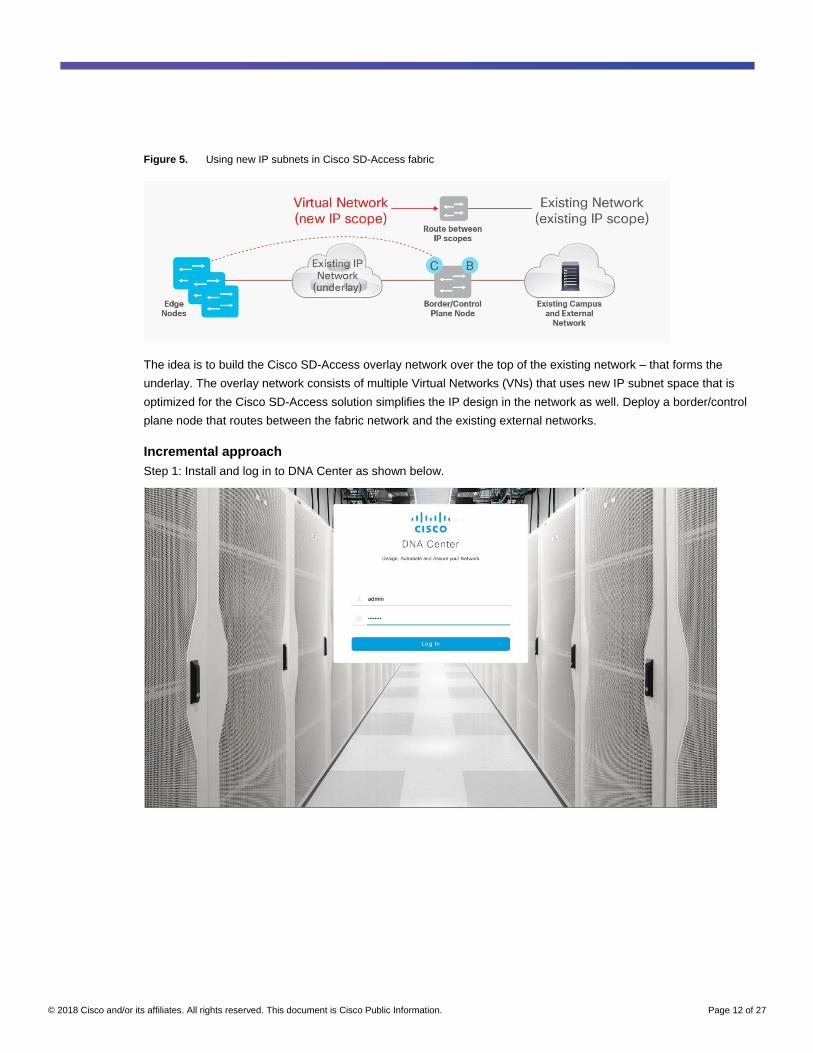
Figure 5. Using new IP subnets in Cisco SD-Access fabric
The idea is to build the Cisco SD-Access overlay network over the top of the existing network – that forms the
underlay. The overlay network consists of multiple Virtual Networks (VNs) that uses new IP subnet space that is
optimized for the Cisco SD-Access solution simplifies the IP design in the network as well. Deploy a border/control
plane node that routes between the fabric network and the existing external networks.
Incremental approach
Step 1: Install and log in to DNA Center as shown below.
© 2018 Cisco and/or its affiliates. All rights reserved. This document is Cisco Public Information. Page 13 of 27
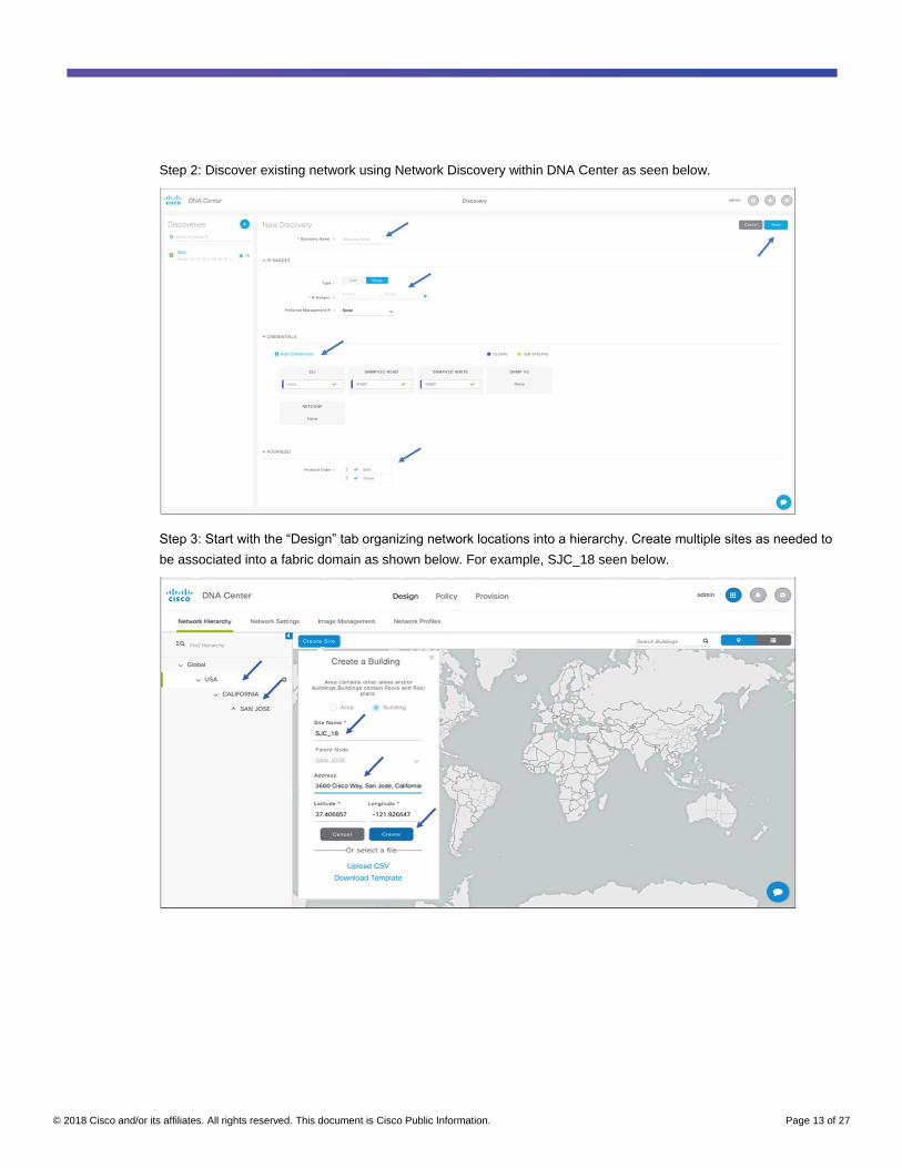
Step 2: Discover existing network using Network Discovery within DNA Center as seen below.
Step 3: Start with the “Design” tab organizing network locations into a hierarchy. Create multiple sites as needed to
be associated into a fabric domain as shown below. For example, SJC_18 seen below.

© 2018 Cisco and/or its affiliates. All rights reserved. This document is Cisco Public Information. Page 14 of 27
Step 4: Configure basic network settings as shown below.
© 2018 Cisco and/or its affiliates. All rights reserved. This document is Cisco Public Information. Page 15 of 27
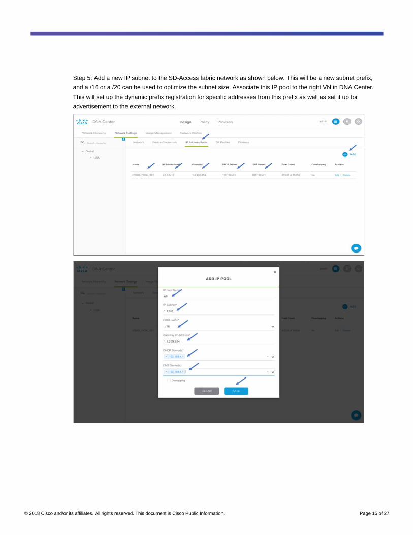
Step 5: Add a new IP subnet to the SD-Access fabric network as shown below. This will be a new subnet prefix,
and a /16 or a /20 can be used to optimize the subnet size. Associate this IP pool to the right VN in DNA Center.
This will set up the dynamic prefix registration for specific addresses from this prefix as well as set it up for
advertisement to the external network.
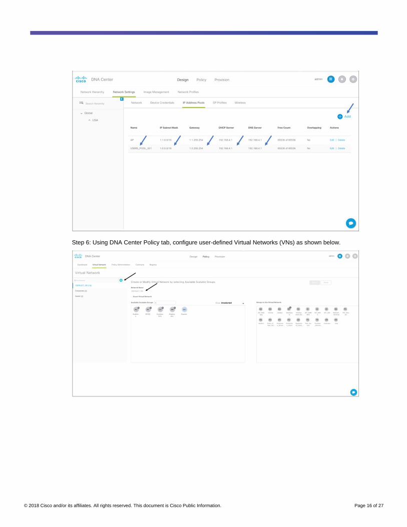
© 2018 Cisco and/or its affiliates. All rights reserved. This document is Cisco Public Information. Page 16 of 27
Step 6: Using DNA Center Policy tab, configure user-defined Virtual Networks (VNs) as shown below.
© 2018 Cisco and/or its affiliates. All rights reserved. This document is Cisco Public Information. Page 17 of 27
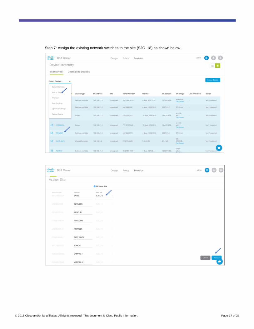
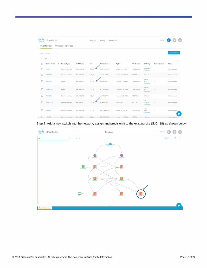
Step 7: Assign the existing network switches to the site (SJC_18) as shown below.
© 2018 Cisco and/or its affiliates. All rights reserved. This document is Cisco Public Information. Page 18 of 27
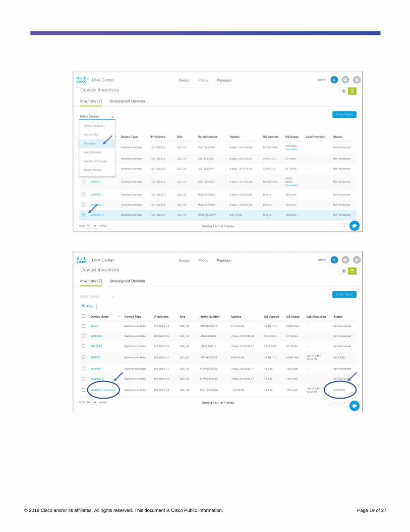
Step 8: Add a new switch into the network, assign and provision it to the existing site (SJC_18) as shown below.
© 2018 Cisco and/or its affiliates. All rights reserved. This document is Cisco Public Information. Page 19 of 27
© 2018 Cisco and/or its affiliates. All rights reserved. This document is Cisco Public Information. Page 20 of 27
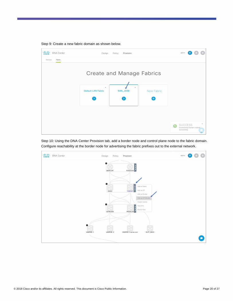
Step 9: Create a new fabric domain as shown below.
Step 10: Using the DNA Center Provision tab, add a border node and control plane node to the fabric domain.
Configure reachability at the border node for advertising the fabric prefixes out to the external network.
© 2018 Cisco and/or its affiliates. All rights reserved. This document is Cisco Public Information. Page 21 of 27
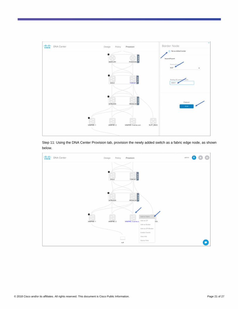
Step 11: Using the DNA Center Provision tab, provision the newly added switch as a fabric edge node, as shown
below.
© 2018 Cisco and/or its affiliates. All rights reserved. This document is Cisco Public Information. Page 22 of 27
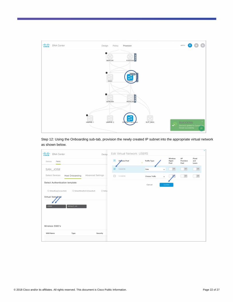
Step 12: Using the Onboarding sub-tab, provision the newly created IP subnet into the appropriate virtual network
as shown below.
© 2018 Cisco and/or its affiliates. All rights reserved. This document is Cisco Public Information. Page 23 of 27
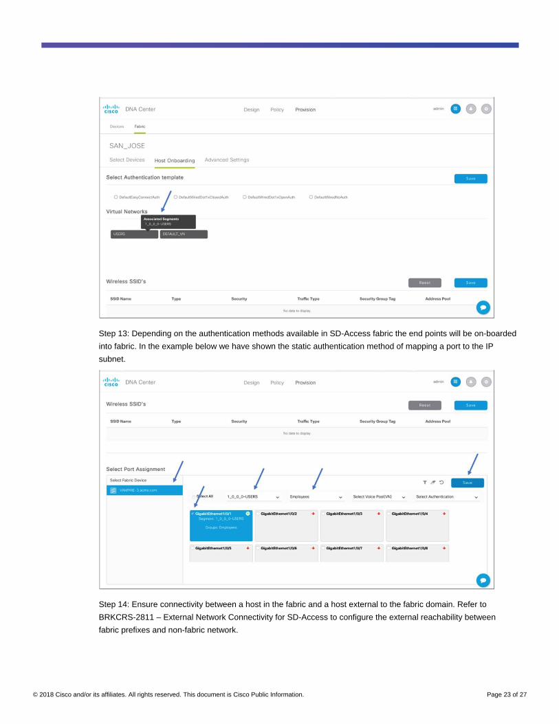
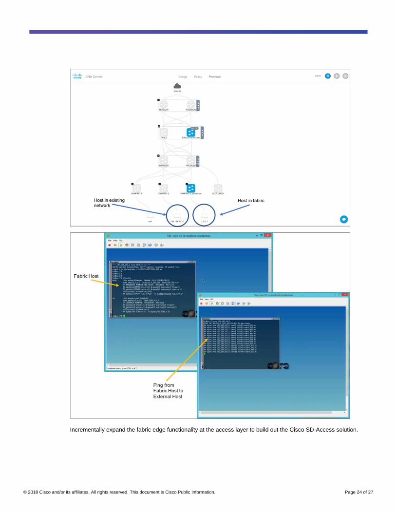
Step 13: Depending on the authentication methods available in SD-Access fabric the end points will be on-boarded
into fabric. In the example below we have shown the static authentication method of mapping a port to the IP
subnet.
Step 14: Ensure connectivity between a host in the fabric and a host external to the fabric domain. Refer to
BRKCRS-2811 – External Network Connectivity for SD-Access to configure the external reachability between
fabric prefixes and non-fabric network.
© 2018 Cisco and/or its affiliates. All rights reserved. This document is Cisco Public Information. Page 24 of 27
Incrementally expand the fabric edge functionality at the access layer to build out the Cisco SD-Access solution.
© 2018 Cisco and/or its affiliates. All rights reserved. This document is Cisco Public Information. Page 25 of 27
Service interworking with SD-Access
When we are upgrading the traditional network into SD-Access fabric we are introducing a concept of virtual
network (VRF) in the fabric. Due to this introduction of the additional policy construct we need to be able still
communicate to our service’s infrastructure. The Services infrastructure generally reside outside the fabric domain
and contain the following elements:
● Identity services (such as AAA/RADIUS)
● DNS
● Dynamic Host Configuration Protocol (DHCP)
● IP Address Management (IPAM)
● Monitoring tools (such as SNMP)
● Data collectors (such as NetFlow and Syslog)
● Firewalls
● Other infrastructure elements
Since these reside outside of the fabric, the border is responsible for interconnecting the fabric with the services
infrastructure. The services infrastructure will generally be deployed using two models:
1) Shared services in global routing table
2) Shared services in dedicated VRF table
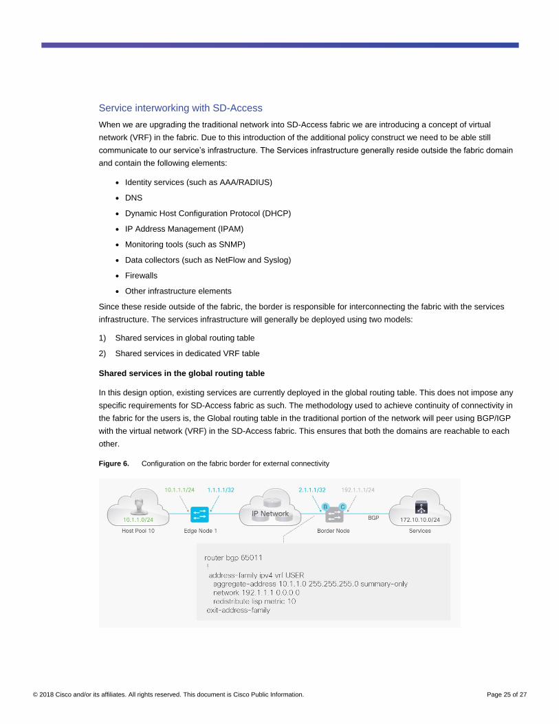
Shared services in the global routing table
In this design option, existing services are currently deployed in the global routing table. This does not impose any
specific requirements for SD-Access fabric as such. The methodology used to achieve continuity of connectivity in
the fabric for the users is, the Global routing table in the traditional portion of the network will peer using BGP/IGP
with the virtual network (VRF) in the SD-Access fabric. This ensures that both the domains are reachable to each
other.
Figure 6. Configuration on the fabric border for external connectivity
© 2018 Cisco and/or its affiliates. All rights reserved. This document is Cisco Public Information. Page 26 of 27
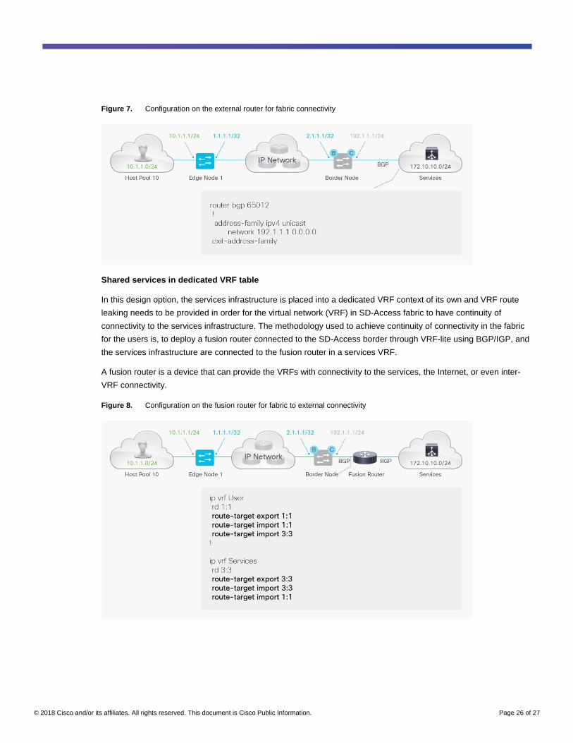
Figure 7. Configuration on the external router for fabric connectivity
Shared services in dedicated VRF table
In this design option, the services infrastructure is placed into a dedicated VRF context of its own and VRF route
leaking needs to be provided in order for the virtual network (VRF) in SD-Access fabric to have continuity of
connectivity to the services infrastructure. The methodology used to achieve continuity of connectivity in the fabric
for the users is, to deploy a fusion router connected to the SD-Access border through VRF-lite using BGP/IGP, and
the services infrastructure are connected to the fusion router in a services VRF.
A fusion router is a device that can provide the VRFs with connectivity to the services, the Internet, or even inter-
VRF connectivity.
Figure 8. Configuration on the fusion router for fabric to external connectivity
© 2018 Cisco and/or its affiliates. All rights reserved. This document is Cisco Public Information. Page 27 of 27
Summary
This guide helps you understand the different upgrade options available to convert a traditional network to an SD-
Access fabric network.
Printed in USA C07-739524-01 05/18