Embed Size (px)
Citation preview
Cisco Small Business Unified Communications UC320W
ADMINISTRATION GUIDE

© 2011 Cisco Systems, Inc. All rights reserved. 78-19371-01 Rev. B0
Cisco and the Cisco Logo are trademarks of Cisco Systems, Inc. and/or its affiliates in the U.S. and other countries. A listing of Cisco's trademarks can be found
at www.cisco.com/go/trademarks. Third party trademarks mentioned are the property of their respective owners. The use of the word partner does not imply
a partnership relationship between Cisco and any other company. (1005R)
Contents
Chapter 1: Welcome 9
System Requirements 9
Optional Equipment and Services 10
Getting Started with the Cisco UC320W 11
Getting Started - Introductory Tutorial 11
Getting Started - Network Topology 11
Getting Started - Firmware and Cloud Services 11
Getting Started - LAN Devices 12
Configuration Module Overview 13
Navigation for a New Configuration 13
Data Entry in the Configuration Module 14
Saving a Session 15
Loading a Saved Session or an Applied Configuration 15
Backing Up and Restoring the Configuration 16
Critical Updates 17
Features of the Help System 18
Sending Feedback to Cisco 18
Logging Out 18
Chapter 2: Site 19
Region 19
System Access 20
Administrative User 20
Remote Access 20
Automatic Maintenance 21
Maintenance Window 21
USB Backup 22
Cisco Unified Communications UC320W Administration Guide 3
Contents
Chapter 3: Telephony 23
Devices 23
General Information and Options for Devices 23
Adding and Removing Cisco SPA8800 IP Telephony Gateways 24
Adding and Removing IP Phones and Side Cars 24
PBX/Key System 26
PBX 26
Key System 26
Blend 27
Day/Night Features 27
Call Scheduling 27
Select Schedule Behavior 28
Internal Dialing 31
Extension Length 31
Allowed Dial Patterns 31
Extensions for System Features 32
Music 33
Chapter 4: Ports and Trunks 34
Line (FXO) Ports 34
General Information and Options 34
Settings for FXO Ports 35
Troubleshooting Tools for FXO Trunks 35
FXO Gain Settings 35
FXO Impedance Matching 36
FXS Ports 37
SIP/BRI Trunks 37
About SIP/BRI Trunks 37
Adding and Removing SIP/BRI Trunks 38
SIP Provider Settings 38
Mediatrix Gateway Settings 40
Cisco Unified Communications UC320W Administration Guide 4
Contents
Systemwide SIP Parameters 40
Outbound Trunks 41
Chapter 5: Users/Phones 43
Users 43
General Information and Options 43
Settings for User Records 44
Other Data Entry Options 44
Assign Phones 46
About the Phone Assignments 46
Managing Phone Assignments 46
Chapter 6: Extension Buttons 48
Shared FXO Lines 48
Features of a Shared FXO Line 48
General Information and Options for Shared Lines 49
Settings for Shared FXO Lines 50
Selecting Members for Shared FXO Lines 51
Shared Extensions 52
Features of Shared Extensions 52
General Information and Options for Shared Extensions 53
Shared Extension Settings 53
Selecting Members for Shared Extensions 54
Additional Extensions 55
General Information and Options for Additional Extensions 55
Settings for Additional Extensions 56
Chapter 7: Call Routing 57
Call Paging 57
External Paging 57
Paging Groups 58
Cisco Unified Communications UC320W Administration Guide 5
Contents
Hunt Groups 59
Features of Hunt Groups 59
General Information and Options for Hunt Groups 60
Hunt Group Settings 60
Selecting Members for Hunt Groups 61
Auto Attendant 62
Settings for AA Menus 62
Buttons for AA Menus 63
Setting Up Prompts 64
Settings for AA Prompts 64
Using the AA Prompts Recorder 66
Inbound Calls 67
General Information and Options for Inbound Routing 67
Settings for Routing Groups 67
Specifying Phone Numbers with Different Destinations 68
Chapter 8: User/Group Features 69
Call Forwarding 69
Voicemail to Email 70
Phone Buttons 71
General Information and Options for Phone Buttons 71
Settings for Phone Buttons 72
Phone Button Labels 74
Directory 75
Chapter 9: Network 77
Topology 77
WAN 77
LAN 80
General Information and Options for LAN Settings 80
Data VLAN and Voice VLAN Settings 80
Cisco Unified Communications UC320W Administration Guide 6
Contents
Wireless 81
Port Forwarding 82
General Information and Options for Port Forwarding 82
Settings for Port Forwarding 83
Chapter 10: Apply Changes 84
Site Summary 84
Apply Configuration 85
Chapter 11: Status Module 86
Quick View 86
Devices 87
Networks 89
DHCP Clients 90
Voicemail 91
External Trunks 92
External Call Records 92
Troubleshooting 93
Chapter 12: How Do I 95
Appendix A: Installation Options for the Unified Communications System 102
Wall Mounting 103
Optional Power Cord Retention Kit 105
Appendix B: Installing Phones and Attendant Consoles 106
Phone Connections 107
Cisco SPA301 Connections 107
Cisco SPA303 and SPA500 Series Connections 108
Cisco Unified Communications UC320W Administration Guide 7
Contents
Installing a Desk Stand (Optional) 109
Mounting a Phone to a Wall (Optional) 110
Attaching and Installing the Wall Mount Bracket Kit 110
Reversing the Handset Retention Tab 115
Connecting the Power 117
Connecting a Phone to the Network 117
Connecting a Phone with an Ethernet Cable 117
Connecting a Cisco SPA525G/G2 Model Phone to the UC320W Wireless Voice Network 117
Connecting a PC to a Phone (Optional) 119
Upgrading the Phone Firmware 119
Connecting Attendant Consoles 119
Appendix C: Where to Go From Here 124
Cisco Unified Communications UC320W Administration Guide 8
1
Welcome 1
The Cisco UC320W Configuration Utility helps you to configure your Unified
Communications System quickly and easily.
The dynamic user interface has two modes to help you to install, configure, and
manage your Unified Communications System.
• Initial setup: When you create a new configuration, the user interface
makes it easy to connect to services, install the equipment, and configure
the features for your site. First you use the Getting Started menu to
complete the essential installation tasks. Then, in the Configuration module,
the interface guides you step by step through the configuration process. As
you work, you also can access the Status menu to view information.
• Ongoing management: When you work from an applied configuration, the
user interface makes it easy to monitor and maintain the Unified
Communications System. The Quick View page provides an overview of the
status. Use the links in the Quick View page and in the navigation tree to
view detailed information about the network, the devices, and the telephony
system. You also can view call detail records and system logs. You also can
access the Configuration menu to review or modify the settings.
System Requirements
• Computer with a web browser. Cisco recommends Internet Explorer
version 7 or later or Firefox version 3.6 or later. For best results, set the
screen resolution to 1024x768 or higher.
• Adobe Flash Player version 10.1 or later.
• Cisco SPA300 Series or Cisco SPA500 Series IP phones. You can have up
to 24 users. This count includes all IP phones and all enabled FXS ports on
Cisco SPA8800 IP telephony gateways. Note: The built-in FXS port on the
Cisco UC320W also can be configured for a user and does not count
toward the 24-user limit.
Cisco Unified Communications UC320W Administration Guide 9
Welcome
Optional Equipment and Services
1
• Power adapters for the phones, as needed. Cisco SPA300 Series phones
always require power adapters. Cisco SPA500 Series phones can receive
power from a Power over Ethernet switch.
• Ethernet cables to connect IP phones and computers.
• For wireless operation, securely connect the antennas to the base unit.
Signal loss can result if an antenna is not seated properly.
• Internet service.
• Voice over IP service or analog phone service.
Optional Equipment and Services
• Secure router for Internet access: Cisco recommends using a secure router,
such as a Cisco SRP500 Series Services Ready Platform or a Cisco SA500
Series Security Appliance.
• Additional ports for IP phones and network devices: You can add ports by
connecting a Cisco ESW500 Series Power over Ethernet Switch to a LAN
port. Other switches may be used but may require configuration of VLAN
and QoS settings (Voice VLAN 100, default voice VLAN subnet 10.1.1.1).
More information is available in the Cisco UC320W Smart Designs. Note: An
Ethernet hub is not recommended for use in a Voice over IP network.
• Additional ports for analog devices and analog phone lines: You can add up
to two Cisco SPA8800 IP telephony gateways with 4 FXO ports and 4 FXS
ports. All enabled FXS ports on the gateways count toward the 24-user
limit. Note: The built-in FXS port on the Cisco UC320W also can be
configured for a user and does not count toward the 24-user limit.
• ISDN BRI service: Install up to two Mediatrix 4400 Digital Gateways.
Connect the Cisco UC320W and the BRI gateways to a secure router such
as a Cisco SA500 Series Security Appliance. Application notes are
available with the Cisco UC320W technical documentation on cisco.com.
• Power cord retention kit: To prevent accidental removal of the power cord,
you can install the supplied power cord retention kit. Remove the screw
next to the power port. Connect the clamp to the power cord. Insert the
screw and install it onto the Cisco UC320W.
Note: For best results, install the latest firmware for any network devices, such as
routers and Ethernet switches, before proceeding.
Cisco Unified Communications UC320W Administration Guide 10
Welcome
Getting Started with the Cisco UC320W
1
Getting Started with the Cisco UC320W
The Getting Started menu provides access to essential tasks. Especially if you are
a new user of this tool, it is strongly recommended that you click each link and
perform each task in the specified order. A new window will display more
information about the selected task. Experienced users may choose to skip tasks.
After completing the final step to connect the LAN devices, you can click the
Begin configuration button to proceed into the Configuration module.
Getting Started - Introductory Tutorial
You can launch the tutorial from the Getting Started menu or the Help menu near
the top right corner of the window. If you are using the configuration utility for the
first time, you may find it helpful to watch this short video to become familiar with
the features. After viewing the video, close the pop-up window.
Getting Started - Network Topology
Choose your network topology. To view more information about an option, position
your mouse pointer over the pointer icons on the screen. Choose your topology,
enter any required settings, and then click Apply Now. The Cisco UC320W will
reboot as the settings are applied. Depending on the topology changes, you may
need to align your PC with new network addressing. You also may need to
reconnect to the configuration utility by entering a new LAN IP address into the
web browser.
Caution: This task is especially important if you are installing the Cisco UC320W
in a network where another device acts as the DHCP server. IP address conflicts
will result if two DHCP servers exist on the same network. If you have another
DHCP server, be sure to complete this task before you connect any LAN devices.
Getting Started - Firmware and Cloud Services
Configure your Internet connection to enable access to the web. Although you can
click Skip and complete this step later, it is recommended that you enable your
Internet connection immediately.
When your Internet connection is enabled, the Cisco UC320W Configuration Utility
accesses the following types of Cloud Features:
• Additional Help menu items, such as Small Business Support Community
Cisco Unified Communications UC320W Administration Guide 11
Welcome
Getting Started with the Cisco UC320W
1
• Additional top-level menu items running Cloud Applications, such as a
Feedback form
• A Cloud Application that runs automatically and may perform any of the
following functions:
- Offers firmware upgrades that you can install with the click of a button
- sends notifications providing helpful information for UC320W
administrators
- remotely administers PMF files
- collects system information, such as configuration files (excluding
passwords), installed firmware, PMF files, and language settings
WAN Settings
WAN Type: Choose the type of Internet connection that is required by your
service provider. Then enter the information for the selected WAN type. (A DHCP
connection is made automatically.) Refer to the information provided by your
service provider for your Internet service account. For information about the fields
on the screen, you can position your mouse pointer over a field to view a tooltip.
After entering your settings, click Apply Now to apply the settings immediately.
If you want to upgrade the firmware by using a file from your PC, click Upgrade
from your PC, and select the file.
Getting Started - LAN Devices
At this point in the Getting Started process, you can install the phones, Cisco
SPA8800 IP telephony gateways, and computers. Use Ethernet cables to connect
these devices directly to the Cisco UC320W LAN ports, or connect an Ethernet
switch to a LAN port and then connect the devices to the LAN ports of the switch.
After the devices are detected, status information appears on the screen. This
process may take some time.
When you are finished connecting devices, click All Devices Connected.
Note: Cisco recommends using a Cisco ESW500 Series Ethernet Switch with
Power over Ethernet. Other switches may be used but may require configuration
of VLAN and QoS settings. The default Voice VLAN is VLAN 100. The default Voice
VLAN Subnet is 10.1.1.x. For more information about deployment options, see the
Smart Designs.
Cisco Unified Communications UC320W Administration Guide 12
Welcome
Configuration Module Overview
1
Caution: If you are using another device as the DHCP server for your LAN, do not
connect devices until you complete the Network Topology task.
Configuration Module Overview
In the Configuration module, the interface guides you step by step through the
configuration process. Before you begin, you should read the information below to
become familiar with the navigation and data entry features.
IMPORTANT: The settings are not applied to the devices until you apply the
configuration. If you close the configuration module without applying the
configuration or saving your settings, any unsaved changes are abandoned.
Navigation for a New Configuration
• Order of tasks: When creating a new configuration, you must proceed
through the steps in the prescribed order. Click Next to advance to the next
step, or click Back to return to the previous page. Use the links in the
navigation tree to return to any page that you viewed previously. Links are
unavailable for pages that you have not yet viewed.
• Omitting steps: On most configuration pages, if you are unsure or not ready
to enter the settings, you can click Next to skip that step. You can return to
those tasks in later sessions, as needed. Error messages will appear if you
attempt to skip a required step.
• Navigation tree icons: Icons appear in the navigation tree to indicate the
status of each configuration task:
- Blue flag: Changes were made.
- Red X: There are validation errors on this page. You cannot apply the
configuration until all errors are fixed.
• Summary pages: At the end of each section, a Summary page appears.
You can review the settings from each page within the section. Hyperlinks
make it easy to jump to a page and change the settings. The system
automatically saves your settings after you click Next.
• Auto-Save for a new configuration: For a new configuration, the system
automatically saves your settings as you advance from each Summary
page. You also can save your session by clicking the Save button in the
menu bar.
Cisco Unified Communications UC320W Administration Guide 13
Welcome
Configuration Module Overview
1
• Returning to the Getting Started menu: Until you apply the configuration,
you can return to the Getting Started menu by clicking the Getting Started
button in the menu bar.
• Starting over: To restart in initial setup mode, click the New button in the
menu bar. Note: Creating a new configuration will reinitialize your
configuration settings. To reset the Cisco UC320W to the factory default
settings, press and hold the Reset button for 10 seconds.
• Viewing the Status pages: To view system status information, click the
Status button in the menu bar.
Data Entry in the Configuration Module
• Show/hide buttons: To simplify the display, some features are hidden until
you need to use them. As you start entering information on a page,
additional features may appear. Several pages include buttons that you can
click to show or hide fields.
• Scrolling: On some pages, you may need to use the vertical or horizontal
scroll bars to view all of the fields.
• Required fields: Required fields are indicated by an icon next to the field
name.
• Errors: If you omit required information or enter invalid information, an error
message appears. A red X icon also appears next to the field and in the
navigation bar next to the name of the configuration page. You can click the
Next button to continue without fixing the errors, but you will not be able to
apply the configuration until the errors are resolved.
• Applying a new configuration: At the end of the initial setup process, the
Apply Configuration page appears. If any errors appear, resolve them. Then
apply the configuration and wait for all devices to restart with the new
settings. Your settings are not applied to the devices until you complete this
task.
• Working from an existing configuration: After applying a configuration,
you can view the Status pages or use the Configuration module to review
and update your settings. When you are ready to apply your changes, click
the Apply Configuration link near the lower right corner of the page, or click
the Apply Changes > Apply Configuration link in the navigation tree. If any
errors appear, resolve them. Then apply the configuration and wait for all
devices to restart with the new settings. Your settings are not applied to the
devices until you complete this task.
Cisco Unified Communications UC320W Administration Guide 14
Welcome
Configuration Module Overview
1
Saving a Session
If you need to close the configuration utility before applying your configuration,
you can save your session. The session file includes the settings that you have
entered, but does not include voicemail messages, recorded prompts, FXO gain
settings, or Platform Management Files. Click the Save button in the menu bar.
Then choose one of the options described below.
• Save Session to Device: Choose this option to save the current unapplied
configuration as a file on the Cisco UC320W. Enter a Description, and then
click Save.
• Save Session to File: Choose this option to save the current unapplied
configuration as a file on your PC. Then click Save. When the pop-up
window appears, save the file on your PC.
Note:
• The administrator username and password are not saved in this procedure
and therefore are not overwritten when you load a saved session.
• Recorded prompts and voicemail messages are not saved with your
session. These files are saved only when you create a full site backup by
using a USB key. For more information see the Backing Up and Restoring the Configuration section below.
• You can restore a saved session by using the Load button. For more
information, see the Loading a Saved Session or an Applied Configuration
section below.
• In this process, you are not applying the configuration to the devices, but
are saving files that you can work from in future sessions, if needed.
Loading a Saved Session or an Applied Configuration
To resume a saved session or to reload the currently applied configuration from
the device, click the Load button in the menu bar. Then choose one of the options
described below.
• Resume session from device: Choose this option to resume a session that
was saved to the Cisco UC320W by using the Save button. You also can
restore a file that was saved by the Auto-Save feature. After you click the
Resume session from device option, choose a saved session or Auto-Save
file from the drop-down list. Then click Load.
Cisco Unified Communications UC320W Administration Guide 15
Welcome
Configuration Module Overview
1
• Load applied configuration from the device: This option allows you to
abandon your unsaved changes and reload the currently applied settings
into the configuration utility for editing. After you choose this option, click
Load.
• Resume session from a saved file: Choose this option to resume a session
that was saved to your PC by using the Save button. Click the radio button,
and then click Choose File to select the file from your PC. Finally, click Load.
Note: The existing administrator username and password are not saved in the
session file and therefore are not overwritten when you reload a session. Continue
to log on with your current username and password.
Backing Up and Restoring the Configuration
You can save the currently applied configuration as a file on your PC, or you can
create a full site backup including the site configuration, recorded prompts, and
voicemail messages by using a USB key. You easily can restore a saved
configuration or a full site backup.
As a best practice, you should save the configuration or create a full site backup
before you make significant changes in your configuration. Then if you are
unhappy with your changes, you easily can restore the previous configuration.
IMPORTANT: After restoring a configuration file, log in, and then re-apply the
configuration.
Note:
• To allow file transfers, temporarily disable the pop-up blocker in your web
browser's Internet options.
• The Full Site Backup option is available only after you have applied a
configuration.
• Voicemail access is interrupted while the backup is being saved. Therefore,
Cisco recommends performing this procedure during a period when users
and callers are unlikely to require voicemail access.
To back up or restore the configuration, click the Backup/Restore link near the top
right corner of the configuration utility window. In the Backup/Restore window,
choose one of the options described below.
Note: Due to the large file size, do not use a wireless connection to back up the
configuration.
Cisco Unified Communications UC320W Administration Guide 16
Welcome
Configuration Module Overview
1
• Restore Site Configuration: Choose this option to restore a site
configuration that you saved by using the Save Site Configuration option.
After you choose this option, click Choose File. Choose a saved tar.gz file
from your PC or network drive. Finally, click Restore.
• Restore Full Site Backup from USB: Choose this option to restore and
apply a full site backup file, including all settings, recorded prompts, and
voicemail messages. This option is available after you insert a USB key into
the USB1 or USB2 slot. The USB key must be in FAT32 format. NTFS is not
supported. If both USB slots have USB keys, two drop-down lists appear.
Choose a file, and then click Restore from USB. Note: Restoring voicemail
messages may take minutes to hours, depending on the amount of
voicemail.
• Save Site Configuration: Choose this option to save your configuration,
including all settings but not including voicemail messages, recorded
prompts, FXO Gain settings, or Platform Management Files. After choosing
this option, click Save. When the download pop-up window appears, save
the file on your PC. Tip: The file name indicates the date and time of the
backup.
• Save Full Site Backup to a USB Key: Choose this option to save a full site
backup file, including all settings, voicemail greetings, voicemail messages,
Auto Attendant prompts, FXO gain settings, and platform modification files.
This option is available after you insert a USB key into the USB1 or USB2
slot. The USB key must be in FAT32 format. NTFS is not supported. If both
USB slots have USB keys, select the USB slot where you want to save the
file. Then click Save to USB.
Critical Updates
After you log in, you may see a Critical Update Available message. This Cloud
Services message indicates that a recent firmware update is available. You can
upgrade immediately by clicking the Upgrade button. If you want to review your
settings or save a site backup before upgrading, you can click the Upgrade Later
button. In this case, an Update Available link will appear near the top right corner
of the configuration utility window. When you are ready, click the link to open the
Critical Update Available window, and proceed with the upgrade.
Note: For best results, close other browser windows first. When other browser
windows are open, the browser may display memory errors.
Cisco Unified Communications UC320W Administration Guide 17
Welcome
Configuration Module Overview
1
Features of the Help System
• Tooltips: For help with a field, button, or tab, position your mouse pointer
over the object. Information appears in a tooltip.
• Page Help (if applicable): To view information about the current page, click
the question mark icon near the top right corner of the page. To hide the
Help, click the icon again.
• System Map: The System Map is a reference tool that indicates the devices
and services that you are configuring on the current page. Near the top right
corner of each configuration page, click the map icon to display the System
Map. To hide the map, click the icon again.
• Additional Help resources: To access the complete Help table of contents,
the introductory video, and other Help resources, use the Help link near the
top of the configuration utility window.
Sending Feedback to Cisco
Cisco welcomes feedback from our customers. To send your comments and
suggestions, click the Feedback link near the top right corner of the window. This
link appears after cloud (WAN access) features are enabled. Then choose a
Category, and type your comments in the Issues or suggestions box. Also take a
moment to provide a Rating for this configuration utility. Finally, click Send.
Logging Out
To log out immediately, click the Log Out link near the top right corner of the
window. Any unsaved changes are abandoned.
Cisco Unified Communications UC320W Administration Guide 18
2
Site 2
In the Site section of the Configuration module, you configure the regional settings,
system access, and automatic backups.
Region
Use the Configuration > Site > Region page to specify your region, regional dial
plan option (if available), and time zone.
Note: Internal Dialing plan settings, such as extension length and digits for outside
lines, are set on the Internal Dialing page.
• Region: Select your region. This setting determines the language for the
text on the phone screen, the default prompts for the Auto Attendant and
the Voicemail Pilot, the regional dial plan, and the regional call processing
tones.
• Dial Plan: If multiple options are available for your region, choose from the
drop-down list. For example, in North America, you can choose a 7-digit or a
10-digit dial plan. Complete any additional fields that appear.
• Default Area Code: If you chose the North American 7-digit dial plan, enter
the area code for your site.
• Time Zone: Choose the time zone for your site.
• Use Daylight Savings: Check this box if you want the system automatically
to adjust the clock for daylight savings time.
Cisco Unified Communications UC320W Administration Guide 19
Site
System Access
2
System Access
Use the Configuration > Site > System Access page to update the administrator
username and password. Optionally, enable access to this utility from the WAN
and the wireless network.
Note:
• Changes in the username and password take effect after you apply a
configuration.
• The configuration utility allows only one session at a time.
Administrative User
To change the username and password, click the Change administrator
username/password button. Then enter the following information:
• Admin Username: Enter a username for the system administrator. The first
character must be a letter. The following characters are valid: A-Z a-Z 0-9
!*_.( ) Neither cisco nor admin is allowed in any form.
• Password: Enter a password for the system administrator. The password
must begin with a letter and is case sensitive. Neither cisco nor admin is
allowed in any form. To help prevent unauthorized access, you should use a
strong password that includes lowercase and uppercase letters and
numbers.
• Confirm Password: Enter the same password again, for confirmation. The
passwords must match.
Remote Access
• Enable remote management of the Cisco UC320W via HTTPS: Check
this box to allow access to the configuration utility from the WAN side of the
Cisco UC320W. After enabling this option, you can access the configuration
utility from the WAN by entering the Cisco UC320W WAN IP address and
the port number, as shown in the following example: https://WAN_ipaddress:8080. Keep the default port number shown, or enter
another port number. As shown in the example, a port number is required
when entering the address.
Cisco Unified Communications UC320W Administration Guide 20
Site
Automatic Maintenance
2
Note:
- Do not change the port number to 443. Because this port is used by SSL
and HTTPS, web browsers tend to remove it from a URL when entered.
However, the configuration utility requires a port number to be specified.
- A remote management session is disconnected after a long idle time.
- If the Cisco UC320W is located behind another router, you may need to
configure port forwarding on that router to allow traffic from the WAN to
the Cisco UC320W.
• Enable wireless management of the Cisco UC320W: Check this box to
allow access to the configuration utility from a computer that is connected
to the wireless network. Be aware of security issues when submitting
passwords wirelessly. Do not use a wireless connection to upgrade the
firmware or to back up the configuration.
Automatic Maintenance
Use the Configuration > Site > Automatic Maintenance page to schedule system
maintenance tasks and to enable automated backups to a USB key.
Maintenance Window
Automatically, on the specified schedule, the Cisco UC320W runs diagnostics. At
the end of this process, the Cisco UC320W reboots. Schedule a convenient time
when your users will not be impacted.
• Time: Choose the time of day to perform the maintenance tasks, including a
system reboot.
• Day: Choose a day. The maintenance tasks will be performed automatically
each week on the specified day.
Cisco Unified Communications UC320W Administration Guide 21
Site
Automatic Maintenance
2
USB Backup
Use a USB key in FAT32 format. NTFS is not supported. The USB key should have
storage capacity of at least 128MB, preferably 1GB. Insert your USB key into the
USB1 or USB2 port.
The backup file will include all settings, voicemail greetings, voicemail messages,
Auto Attendant prompts, FXO gain settings, and platform modification files. Up to
two files will be stored on the USB key at any time. If two files already exist, the
older file will be replaced with the new file.
Caution: Configuration files include confidential information, such as your email
and SIP/BRI account passwords. Use appropriate precautions to protect your
data.
• Enable USB Backup: Check this box to enable automated backups, or
uncheck the box to disable this feature.
• USB1, USB2: Choose the USB port to be used.
• Time: Choose the time of day to save the backup.
• Day: Choose whether to save the backup daily or weekly.
Cisco Unified Communications UC320W Administration Guide 22
3
Telephony 3
In the Telephony section of the Configuration module, you manage the IP phones
and IP telephony gateways. You also configure the operational mode, day/night
features, internal dialing plan, and music.
Devices
Use the Configuration > Telephony > Devices page to review the automatically
discovered Cisco SPA8800 IP telephony gateways, IP phones and Cisco
SPA500S expansion modules, also known as attendant consoles or side cars. You
also can manually add gateways, phones and side cars that you intend to install
later.
Note: To configure Mediatrix BRI Gateways, see the SIP/BRI Trunks page.
General Information and Options for Devices
• Devices are automatically discovered when they are connected to the
network. Each device is listed by its model number and MAC address.
• If phones are assigned to users, the user names appear (not applicable
when creating a new configuration). Note: Phones are assigned to users on
the Assign Phones page.
• Icons provide more information:
- Check mark: The device is currently available.
- Plus sign: The device was added manually.
- Question mark: The device previously was active, but its current state is
unknown.
- Exclamation point: The device cannot be configured due to capacity
limits. You can add up to two Cisco SPA8800 IP telephony gateways and
Cisco Unified Communications UC320W Administration Guide 23
Telephony
Devices
3
up to 30 phones on this page. However, the Cisco UC320W supports
only 24 users (not counting the built-in FXS port on the Cisco UC320W).
Adding and Removing Cisco SPA8800 IP Telephony Gateways
You can manually add a Cisco SPA8800 IP telephony gateway that you intend to
connect later.
• Create a SPA8800: Click this button to enter information for a Cisco
SPA8800 that is not yet connected.
• Description: Enter a short description to identify this device on the pages
of the configuration utility.
• MAC Address: Enter the MAC address in the following format:
xxxx.xxxx.xxxx, where x is a number or letter in the MAC address. The MAC
address can be found on the hardware label on the bottom panel of the
device.
• To remove a manually added gateway or missing/unregistered gateway
from the list: Click the delete button (X) for the gateway that you want to
remove. When the confirmation message appears, click OK to delete the
device, or click Cancel to keep the device.
Adding and Removing IP Phones and Side Cars
You can manually add an IP phone that you intend to connect later. You also can
indicate the number of connected side cars for each phone that you add.
Alternatively, you can add phones by importing a list.
• Create a phone: Click this button to enter information for an IP phone that is
not yet connected.
• MAC Address: Enter the MAC address of the phone in the following format:
xxxx.xxxx.xxxx, where x is a number or letter in the MAC address. The MAC
address can be found on the hardware label on the bottom panel of the
phone.
• Model: Choose the phone model.
• Side Cars: Choose the number of side cars that are attached to this phone.
• To download a CSV file as a template for data entry or as a phone list:
Click the Download icon to save a CSV file to use as a template. If you have
Cisco Unified Communications UC320W Administration Guide 24
Telephony
Devices
3
not yet added phones, the file contains a sample record and can be used as
a template for data entry. If you have added phones, the file includes all
phone records. You can open the phones.csv file in a text-editing program
such as Notepad or a spreadsheet program such as Microsoft Excel.
• To enter the phone information in a CSV file: You can use a downloaded
template or create a new CSV file. Edit in a text-editing program such as
Notepad or a spreadsheet program such as Microsoft Excel. You must enter
a valid model number for each phone. Also enter the MAC address, using
the following format: xxxx.xxxx.xxxx, where x is a number or letter. In a text-
editing program, separate the values with commas, and create each entry
on a new line. In a spreadsheet program, enter each value in a separate cell,
and create each entry on a new row. If working from a template, delete the
sample record. Save the file in CSV format. You can then import the file, as
described below. Note: Valid model numbers are SPA301, SPA303,
SPA501G, SPA502G, SPA504G, SPA508G, SPA509G, SPA525G, and
SPA525G2.
• To import a CSV file: Click the Import icon to import a list of phones in a
CSV file that you have prepared. Choose the file, and then click Open. Errors
appear if any values are invalid. The imported phones appear at the bottom
of the Phones list.
• To physically replace a device: If a phone is damaged or needs to be
replaced with a different model, first disconnect it from the network by
removing its network cable from the port of the Cisco UC320W or Ethernet
switch. Then wait about 2 minutes for the Cisco UC320W to detect that the
device was removed. You can now connect the new device, which will
appear on the Devices page when it is automatically detected. You can then
use the Assign Phones page to assign the new phone to the user who
previously had the other phone.
Cisco Unified Communications UC320W Administration Guide 25
Telephony
PBX/Key System
3
PBX/Key System
Use the Configuration > Telephony > PBX/Key System page to choose the
operational mode for the telephony system. Tip: To learn more, use the Help Me
Choose button.
Note: If you change the mode after applying a configuration, errors may appear on
other pages, due to the feature differences described below. Fix the errors before
applying the configuration.
PBX
In PBX mode, users have no direct access to choose a phone line; instead, a trunk
is selected from the pool of available trunks. When placing an outbound call, you
must first press an outbound dialing digit such as 9. There are no shared FXO
(analog) lines (as described for Key System). When you choose PBX mode, the
following features are affected:
• Trunks: Phone service can be provided by SIP/BRI trunks (Voice over IP
service) and FXO (analog) lines.
• Shared FXO Lines: You cannot configure Shared FXO Lines. Note: If you
previously configured your system in another mode, any existing Shared
FXO Lines will be removed.
• Outbound Dialing: You can use personal extensions to place calls to an
external number.
• Internal Dial Plan: You need to specify the digit that is required for
outbound dialing. If you have more than one trunk, you can specify a
different digit for each trunk.
Key System
In Key System mode, users can directly choose an analog phone line by pressing
a shared line button on the phone. All users can monitor all calls on all lines. If a call
is placed on hold by one user, it can be resumed by any other user. When a user
presses a shared line button, the line is immediately seized for an outbound call;
you do not have to enter an outbound dialing digit, such as 9. When you choose
Key System mode, the following features are affected:
• Trunks: Phone service is provided by FXO (analog) lines. You cannot
configure SIP/BRI trunks (Voice over IP service). Note: If you previously
Cisco Unified Communications UC320W Administration Guide 26
Telephony
Day/Night Features
3
configured your system in another mode, any existing SIP/BRI trunks will be
removed.
• Outbound dialing: You cannot use a personal extension to place a call to an
external number. Extensions are for internal calls. For outbound calls, use a
shared line button.
• Internal Dial Plan: No outbound dialing digit is required. For example, you
do not have to dial 9 to get an outside line. Simply select a shared line
button.
• Inbound Routing: Configure inbound routing for each trunk on the Shared
FXO Lines page. The Inbound Calls page is unavailable.
Blend
The system functions like a PBX, as described above, but allows the configuration
of shared FXO (analog) lines, as in a Key System. Outbound calls require a steering
digit except when a Shared FXO Line is selected by pressing a shared line button
on a phone. Both FXO (analog) lines and SIP/BRI trunks may be used. All features
are available for configuration.
Day/Night Features
Use the Configuration > Telephony > Day/Night Features page to choose the
scheduling options for inbound call routing and the Auto Attendant (if enabled).
Call Scheduling
Call Routing
If needed, you can enable different call routing options when your business is
opened or closed. Choose a scheduling option.
• Single Schedule Call Routing: Click this button to use the same call routing
settings for all times of day. You will configure these settings on the Inbound
Calls page.
• Day / Night Call Routing: Click this button to enable different call routing
destinations for day (your open hours) and night (your closed hours).
Selecting this option makes day/night settings available for inbound call
routing and call forwarding.
Cisco Unified Communications UC320W Administration Guide 27
Telephony
Day/Night Features
3
Auto Attendant
When enabled, an Auto Attendant (AA) plays recorded messages to respond to
incoming calls. If needed, you can enable different AA menus when your business
is open or closed.
• On, Off: Click On to enable the Auto Attendant, or click Off to disable this
feature.
• Auto Attendant with Single Menu: Click this button to use the same Auto
Attendant menu for all times of day. You will enter the settings on the Auto
Attendant page.
• Auto Attendant with Day / Night Menu: Click this button to enable a
different Auto Attendant menu for day (your open hours) and night (your
closed hours). You will enter the settings on the Auto Attendant page.
Select Schedule Behavior
If you chose a Day/Night Menu/Schedule option, choose whether to require
manual operation or to enable an automated schedule.
Choose a Schedule:
• Manual Schedule (Force Night button) Choose this option if you want to
enable the Day and Night behaviors by using a Force Night button on a
user's phone. When the business closes, a user presses the Force Night
button to enable the Night behavior. When the business opens, the user
presses the Force Night button to resume the normal operations. To add a
Force Night button to a phone, see the Phone Buttons page.
• Automatic Schedule: Choose this option if you want the Cisco UC320W to
automatically enable the Day and Night behaviors based on the business
hours and holidays that you specify. (The schedule settings are available on
the screen after you select this option.) Tip: Even when a schedule is
enabled, you can force the system to Night mode by pressing a Force Night
button on a user's phone. For example, if your business closes early for a
special event, press the Force Night button to enable the Night behavior.
When the business opens, press the button again to resume using the
automated schedule. To add a Force Night button to a phone, see the Phone Buttons page.
Cisco Unified Communications UC320W Administration Guide 28
Telephony
Day/Night Features
3
Select the hours when the business is open
This section is available if you select the Automatic Schedule option. Specify the
Day (open) and Night (closed) hours, as described below. The Cisco UC320W will
automatically shift between Day and Night behavior based on the specified
schedule. A user can force the system into Night behavior by pressing a Force
Night feature button on a phone, if configured (see the Phone Buttons page.)
• Selecting your open hours: To select your open hours (day), position your
mouse pointer at the time of day when the business opens. Drag your
mouse pointer to the time of day when your business closes. When you
release the mouse button, a green bar indicates the open hours. The gray
areas indicate the closed hours (night). Leave the row blank (all gray) if the
business is closed all day. If you have difficulty using the mouse to expand
or contract the selected hours, click the eraser icon to clear the selection.
Then drag your mouse to select the open hours. For best results, select a
segment by dragging the mouse in one smooth motion. Tip: You can use
this technique to select multiple open periods within a day, such as 8 am. to
12 Noon and 1 p.m. to 5 p.m. (closed from Noon to 1).
• Erasing the selected hours: Click the pencil eraser icon to erase the
selected hours.
Select Holidays
Optionally, you can add holidays. Specify the dates when your business is closed
all day. The Cisco UC320W will automatically shift to Night behavior for each
holiday. Note: This section is available if you chose the Automatic Schedule option.
• To select a date from the calendar: Click the left-arrow button to choose
the previous month, or click the right-arrow button to choose the next
month. Then click the date of the holiday.
• To choose a month from the list: Choose the month when a holiday occurs.
Then click the date of the holiday.
Holidays
Complete the holiday record:
• Yearly: Check this box if this holiday occurs on the same date every year.
• Description: Enter a word or short phrase to identify this holiday.
• To remove a holiday: Click the delete button (X) for the holiday that you
want to remove.
Cisco Unified Communications UC320W Administration Guide 29
Telephony
Day/Night Features
3
• To download a CSV file as a template for data entry or as a holiday list:
Click the Download icon to save a CSV file to use as a template. If you have
not yet added holidays, the file contains a sample record and can be used
as a template for data entry. If you have added holidays, the file includes all
holiday records. You can open the holidays.csv file in a simple text-editing
program such as Notepad or a spreadsheet program such as Microsoft
Excel.
• To enter the holiday information in a CSV file: You can use a downloaded
template or create a new CSV file. Edit in a text-editing program such as
Notepad or a spreadsheet program such as Microsoft Excel.
Notes:
- Include the following information for each holiday, in the following order:
description, day (values 1-31), month (values 1-12), year (four digits),
yearly (enter either true or false).
- In a text-editing program, separate the values with commas, and create
each entry on a new line. Example: Using a text-editing program, you
would enter Christmas on Dec. 25, 2011, as follows:
Christmas,25,12,2011,true
- In a spreadsheet program, enter each value in a separate cell, and create
each entry on a new row. Do not include a heading row.
- If working from a template, delete the sample record before saving your
file.
- Save the file in CSV format. You can then import the file, as described
below.
• Import Holidays: Click the Import icon to import a list of holidays from a
CSV file that you have prepared. Choose the file, and then click Open. Errors
appear if any required values are missing. The imported records appear on
the screen.
Cisco Unified Communications UC320W Administration Guide 30
Telephony
Internal Dialing
3
Internal Dialing
Use the Configuration > Telephony > Internal Dialing page to configure the internal
extension format, the system extensions, and the functions of dialed digits. For
example, specify which digits are used in extension numbers, which digits are
pressed for an outside line, and so on.
Note: The external dial plan is determined by your regional settings (see the
Region page). The external dial plan encompasses settings such as the required
length of a dialed phone number (7 digits or 10 digits, for example) and the call
processing tones that are used.
Extension Length
For Extension Length, specify the length of the internal extension numbers: 2
digits, 3 digits, or 4 digits. To choose the digits that can start each range of
extension numbers, see the Meaning of First Digit Dialed section of this page.
Allowed Dial Patterns
Choose the function that you want to assign to each digit. After you make a
selection, the Dial Pattern field displays an example. For Extensions, the Utilization
field displays the number of possible assignments. For example, with the two-digit
extension length, each selected digit can support up to 10 extensions.
• Dial Immediately: The digit can be used as a one-digit extension number.
For example, the default configuration allows 0 to be used for this purpose,
and assigns 0 as the Auto Attendant extension number. Another option
might be to assign another extension number to the Auto Attendant and
assign 0 to a user, such as your receptionist.
• Extensions: The digit is used as the first digit of an internal extension
number. For example, if you assign this function to the digit 2, and your
extension length is three digits, you will be able to configure extensions
such as 200, 201, 202, and so on.
• Voicemail Prefix: The digit is used to dial a voicemail box. For example, if
this digit is 7, and a voicemail box is 201, then you can press 7201 to leave a
message in this mailbox.
• Outside Line: The digit is used to place an outbound call. For example, you
can press 9 to get an outside line. Not applicable when the system is in Key
System mode.
Cisco Unified Communications UC320W Administration Guide 31
Telephony
Internal Dialing
3
Tip: In PBX mode or Blend mode, if you have FXO trunks and SIP/BRI trunks,
you might want to enable more than one digit to get an outside line. Then on
the Outbound Trunks page you can assign a different digit to each trunk. For
example, users could then press 8 for the FXO trunk and press 9 for the SIP/
BRI trunk.
• Not Allowed: The digit is not allowed as the first digit in a dialing sequence.
If a user presses the digit to initiate a call, an error tone is played.
Extensions for System Features
For each system feature, keep the default settings, or enter an extension number in
the box. Extension numbers must be unique and must comply with dial plan
settings on this page. An error message appears if you enter an invalid or
duplicate extension number. Tip: A quick way to enter a valid extension number is
to click the phone icon next to the extension number field.
Note: By default, 0 is the extension number for the Auto Attendant. However, you
can assign a different number to the AA and use 0 for other purposes. For
example, you could change the AA extension to 300, and use the Users page to
assign 0 to your receptionist.
• Auto Attendant Extension (to call the Auto Attendant): Enter an extension
number that users can dial to reach the Auto Attendant.
• Auto Attendant Prompt Recorder Extension (to record prompts): Enter
an extension number that users can dial to reach the System Configuration
tool to record prompts for the Auto Attendant.
• Voicemail Pilot Extension (to use the voicemail main menu): Enter an
extension number that users can dial to reach the Voicemail Pilot for access
to the voicemail system.
• External Paging Extension (to initiate an external page): If an external
speaker system is connected to the Line Out port, enter an extension
number that users can dial to initiate an announcement through the speaker.
• Music Extension (to hear music): Enter an extension number that users can
dial to hear the music that is configured for music on hold and/or call park.
Cisco Unified Communications UC320W Administration Guide 32
Telephony
Music
3
Music
Use the Configuration > Telephony > Music page to choose the music source and
to enable music for held calls and parked calls. Also set the extension that can be
dialed to listen to the music.
Note: Refer to the on-screen illustration for the location of the LINE IN port, where
you can connect an external music source. You can position your mouse pointer
over the pointer icon to view the picture at a larger size.
• Internal: Use the internal music server for any music feature that is enabled.
A standard music file is stored on the device for this purpose.
• External: Use an external music server for any music feature that is
enabled. You can connect a music player to the LINE IN port for this
purpose. If you select this option but a music source is not detected, the
system will fail over to the internal music source.
• Play music for calls on hold: Check this box to play music for calls that are
placed on hold. Uncheck the box to disable this feature.
• Play music for parked calls: Check the box to play music for calls that are
parked using the Call Park feature. Uncheck the box to disable this feature.
• Play music over External Paging: Check the box to enable an external
music source to be played over an external speaker. This feature requires
having an external music source connected to the Line In port of the Cisco
UC320W, and an external speaker connected to the Line Out port.
• Extension to listen to music: Keep the default number or enter an
extension number that users can dial from an IP phone to listen to the music.
Extension numbers must be unique and must comply with the rules entered
on the Internal Dialing page. An error message appears if you enter an
invalid or duplicate extension number. Tip: A quick way to enter a valid
extension number is to click the phone icon next to the extension number
field.
Cisco Unified Communications UC320W Administration Guide 33
4
Ports and Trunks 4
In the Ports and Trunks section of the Configuration module, you enable the FXO
(analog) trunks, configure the SIP/BRI (Voice over IP) trunks, and enable the FXS
ports for analog devices.
Line (FXO) Ports
Use the Configuration > Ports and Trunks > Line (FXO) Ports page to enable the
FXO ports for your analog phone lines. This configuration page is available if the
System Mode is set to Key System or Blend. (see the PBX/Key System page.)
General Information and Options
• This page displays the FXO ports on your Cisco UC320W and any Cisco
SPA8800 IP telephony gateways that are connected.
• The Cisco UC320W supports up to 12 simultaneous calls across all trunks
(including FXO and SIP/BRI trunks).
• An error message appears if you have not enabled any trunks for outbound
calls (including FXO and SIP/BRI trunks).
• To avoid unnecessary impact on the 24-user limit, enable only the ports
where you will connect a trunk.
Cisco Unified Communications UC320W Administration Guide 34
Ports and Trunks
Line (FXO) Ports
4
Settings for FXO Ports
• Enabled: Check the box to enable the port. Uncheck the box to disable the
port.
Note: Refer to the on-screen illustration for the location of the FXO ports,
where you can connect to your analog phone service. You can position your
mouse pointer over the pointer icon to view the picture at a larger size.
• Label: Type a descriptive label (optional). For example, type the published
phone number, without punctuation or spaces. This label will appear on the
phone screen as a default label for inbound calls, unless another CLID is
provided by the Central Office. It also will identify any Shared FXO Line
buttons that you configure for this trunk. If the label is left blank, a port
description, such as fxo1, will appear.
Troubleshooting Tools for FXO Trunks
These tools are available after you enable at least one FXO port and apply your
configuration.
• Adjust FXO Gain: Use this tool if you experience volume issues on an FXO
trunk. For more information, see the “FXO Gain Settings” section below.
• FXO Impedance Matching: Use this tool if you experience audio quality
issues, such as echo or clipping, with an FXO trunk. For more information,
see the “FXO Impedance Matching” section below.
FXO Gain Settings
Click the Adjust FXO Gain button to adjust the gain (volume) for each FXO port, as
needed. It is usually necessary to make only minor adjustments.
Caution: Improper settings can cause voice quality issues that may include noise,
signal misdetection, and distortion.
Note: Refer to the on-screen illustration for the location of the FXO ports, where
you can connect your FXO (analog) phone lines. You can position your mouse
pointer over the pointer icon to view the picture at a larger size.
• Transmit (dB): Drag the slider left to reduce the volume of the transmitted
audio on the specified port. Drag the slider right to increase the volume.
• Receive (dB): Drag the slider left to reduce the volume of the received
audio on the specified port. Drag the slider right to increase the volume.
Cisco Unified Communications UC320W Administration Guide 35
Ports and Trunks
Line (FXO) Ports
4
• When finished, click Apply Now to immediately apply the new settings. You
can check the new settings by placing calls through your FXO trunks. Make
additional adjustments, if needed.
• To revert to the default settings, click Set to Default or Reset.
• To close the window without applying any changes, click Done.
FXO Impedance Matching
IMPORTANT: For testing, the trunk must be connected to a Cisco UC320W FXO
port. After the test, if you wish to connect the trunk to a Cisco SPA8800 instead,
you can input the recommended settings in the fields for the Cisco SPA8800. Take
care to ensure that you physically connect the trunk to the corresponding
SPA8800 port.
STEP 1 Connect an FXO trunk to an available port on the Cisco UC320W.
STEP 2 In the Phone number for testing box, enter an external phone number that you
can call and answer during the test. Enter the complete phone number, without
spaces or punctuation. No steering digit is required for an FXO call.
STEP 3 Choose the port where you connected the trunk. Refer to the port labels on the
device to ensure that you choose the correct port.
STEP 4 Click the Start button.the Cisco SPA
STEP 5 When your phone rings, answer it, and immediately press the Mute button. The
test will take about 5 minutes. When the status icon and recommended settings
appear, hang up your phone. Note: For more information about the status icons,
position your mouse pointer over the information button on the screen.
STEP 6 In the lower half of the screen, find the port where you want to use this trunk, and
enter the recommended settings. If you choose a port other than the tested port,
physically connect the trunk to the port now. Refer to the port labels on the device
to ensure that you connect the trunk to the correct port.
STEP 7 If needed, repeat the above steps for other trunks.
STEP 8 When finished with all tests, click the Apply button to immediately apply the new
settings. Alternatively, click the Cancel button to close this window without
applying any settings.
Cisco Unified Communications UC320W Administration Guide 36
Ports and Trunks
FXS Ports
4
FXS Ports
Use the Configuration > Ports and Trunks > FXS Ports page to enable the phone
(FXS) ports on the Cisco UC320W and Cisco SPA8800 IP telephony gateways.
These ports support analog devices.
Note: Refer to the on-screen illustration for the location of the FXS ports, where
you can connect analog devices. You can position your mouse pointer over the
pointer icon to view the picture at a larger size.
Enabled: Check this box to enable the port. Uncheck the box to disable the port.
As a best practice, enable the ports only as needed, to avoid unnecessary impact
on the 24-user limit. This limit applies to all IP phones and all enabled FXS ports on
SPA8800 gateways. It does not include the built-in FXS port on the Cisco
UC320W.
SIP/BRI Trunks
Use the Configuration > Ports and Trunks > SIP/BRI Trunks page to enter the
settings for the SIP providers and BRI gateways that provide Voice over IP (VoIP)
services. You can add up to four different services.
Note: This configuration page is available if the System Mode is set to PBX or
Blend. It is not available in Key System mode. (For more information, see the PBX/Key System page.)
About SIP/BRI Trunks
• The Cisco UC320W supports up to 12 simultaneous calls across all trunks
(including FXO and SIP/BRI trunks).
• To configure the dialing prefix for outbound call routing through your FXO
trunks and SIP/BRI trunks, see the Outbound Trunks page.
• To enter the phone numbers and configure the inbound call routing for these
trunks, see the Inbound Calls page.
• After applying your configuration, verify your settings by placing outbound
calls through this trunk. Also use an external phone such as a cell phone to
place a call to the phone numbers for this trunk.
Cisco Unified Communications UC320W Administration Guide 37
Ports and Trunks
SIP/BRI Trunks
4
Adding and Removing SIP/BRI Trunks
• Add a SIP/BRI Trunk: Click this button to add a new SIP/BRI trunk.
• Provider: Choose the type of trunk.
• After choosing a provider, either complete all required fields or delete the
record. An incomplete entry produces an error, indicated by a red X in the
navigation tree.
• To remove a SIP/BRI trunk: Click the delete button (X) for the trunk that you
want to remove.
• To enter a list of phone numbers for a SIP/BRI trunk: See the Inbound Calls
page.
SIP Provider Settings
This section is available after you select a provider. To enter the settings, click
Settings. To hide the settings, click the button again. The required fields are
indicated by icons next to the field names. However, your service provider may
require other settings that are not marked in this manner. Be sure to enter all of the
information from your provider.
• Description: Enter a short description of this service for your reference.
• Proxy: Enter the IP address or domain name of the SIP proxy server.
• Require registration: Check the box if the SIP proxy server requires SIP
registration.
• Outbound Proxy: If your provider specified a proxy for outbound calls,
enter the IP address of the outbound proxy server.
• Call Capacity: Select the maximum number of concurrent calls that are
supported on this trunk by your service provider.
• Prefix dialed numbers with: Check the box if this feature is required by the
SIP provider. When this feature is enabled, the system automatically inserts
the appropriate dialing prefix to an external number (such as +1 in the US or
+44 in the UK, based on the specified Regional Settings).
• Company Name: Enter the business name.
• Account ID (often Account Phone Number): Enter the account ID, which is
usually the main phone number for the trunk.
Cisco Unified Communications UC320W Administration Guide 38
Ports and Trunks
SIP/BRI Trunks
4
• SIP Domain Name: Enter the SIP domain name, if specified by your
provider.
• Authentication ID: If your provider requires SIP authentication, enter the
authentication code for your account. Typically this code is case sensitive.
• Password: If your provider requires SIP authentication, enter the password
for your account. Typically this password is case sensitive.
• SRV Record Lookup: If required by your provider, check this box to use
DNS SRV lookup for Proxy and Outbound Proxy, or leave this box
unchecked to disable SRV lookup.
• SRV Auto Prefix: If you enabled SRV Record Lookup, you can check this
box to automatically prepend the Proxy or Outbound Proxy name with
_sip._udp when performing a DNS SRV lookup on that name. Uncheck the
box not to use this service.
• Local SIP Port: Displays the local port number that is used for this service.
This information is for your reference, if needed.
• NAT Mapping: Check this box if NAT mapping is not provided by your SIP
provider and therefore local NAT mapping is required. Then specify the NAT
settings in the Systemwide SIP Parameters section. Note: Network
Address Translation (NAT) is a function that allows multiple devices on a
private network to share the same public, routable, IP address to establish
Internet connections. To enable VoIP to co-exist with NAT, some form of NAT
traversal is required. Some service providers provide NAT traversal, but
some do not. If you are unsure, check with your SIP provider.
• Send NAT Keep Alive: Check this box to allow the Cisco UC320W to
periodically send Keep Alive messages to the server to maintain the current
NAT mapping. Note: This option is available if you check the NAT Mapping
box.
Note: Other NAT settings are configured in the Systemwide SIP Parameters
section below.
Cisco Unified Communications UC320W Administration Guide 39
Ports and Trunks
SIP/BRI Trunks
4
Mediatrix Gateway Settings
This section is available after you select a provider. To enter the settings, click
Settings. To hide the settings, click the button again. Requirements vary by
provider; refer to the information from your provider.
Note: You can install up to two Mediatrix 4400 Digital Gateways. Connect the
Cisco UC320W and the BRI gateway to a secure router such as Cisco SA500. For
application notes, visit the Small Business Support Community.
• Description: Enter a short description of this service for your reference.
• Mediatrix IP Address: Enter the IP address for the Mediatrix server.
• Call Capacity: Select the maximum number of concurrent calls that are
supported on this trunk by your provider.
• Prefix dialed numbers with: Check the box if this feature is required by the
SIP provider. When this feature is enabled, the system automatically inserts
the appropriate dialing prefix to an external number (such as +1 in the US or
+44 in the UK, based on the specified Regional Settings).
• Account Phone Number: Enter the main phone number for your BRI
service.
• Launch Mediatrix Interface: Click this link to open the Mediatrix
configuration tool (not a Cisco product).
• Local SIP Port: Displays the local port number to be used for this service.
You will need this port number when you configure the Mediatrix Gateway
to interoperate with the Cisco UC320W.
Systemwide SIP Parameters
This section of the page is available after you choose a provider. These settings
apply to all SIP providers.
• Codec: Keep the default setting or choose the codec for outbound calls.
This list includes the appropriate codecs for your region. Tip: G711
provides better audio quality but uses more bandwidth than G729. With
G729, audio is compressed and may be slightly distorted, most noticeably
when music is played.
• Outbound FAX: Choose a fax transmission setting.
• NAT STUN Server: If you enabled NAT mapping for a SIP provider, you can
select this option use a STUN server to discover NAT mapping. This setting
Cisco Unified Communications UC320W Administration Guide 40
Ports and Trunks
Outbound Trunks
4
applies to all configured SIP providers with NAT mapping enabled. Not
applicable to Mediatrix BRI Gateways.
• NAT Server IP Address (text box): Enter the IP address or the hostname of
the NAT STUN Server. Note: This option is available if you enabled NAT
mapping for one or more SIP providers. This setting applies to all SIP trunks.
• Static IP Address for Site: Specify the public static IP address that is used
for Internet connections at your site. Note: This option is available if you
enabled NAT mapping for one or more SIP providers. This setting applies to
all SIP trunks.
• Static IP Address (text box): Enter the publicly routable static IP address
for your site.
Outbound Trunks
Use the Configuration > Ports and Trunks > Outbound Trunks page to specify the
trunks that are selected for each Outside Line digit in your Internal Dialing plan.
Also choose a trunk to use for emergency calls.
Note: This selection is relevant if you enabled multiple trunks. If you enabled only
FXO trunks, or only one SIP/BRI service, this page displays the trunk assignment
for the Outside Line digits.
• Outbound Trunk Assignment: Click the button to show or hide this section.
You can assign one or more trunks to each digit that is used to get an
outside line. You can assign different trunks to different digits. For example,
you may want your users to press 8 for an FXO trunk and 9 for a SIP/BRI
trunk.
• Emergency Calls: Click the button to show or hide this section. Choose a
trunk to use for emergency calls, such as 911 service, if supported by your
phone service provider. Contact your service provider for details. Also
obtain any information that users need to be aware of when placing
emergency calls through the trunk. For example, it may be necessary to
specify the site location when calling an emergency number.
Notes:
• Check the box to select a trunk. The order in which you check the boxes is
the order in which the trunks are used. For example if you select an FXO
trunk first and a SIP provider second, the SIP provider is used only when the
FXO trunk is busy.
Cisco Unified Communications UC320W Administration Guide 41
Ports and Trunks
Outbound Trunks
4
• The FXO group includes all unassigned FXO trunks, meaning those trunks
that are not reserved for Shared FXO Lines (see the Shared FXO Lines
page).
• You can change the order of the trunks by dragging a trunk up or down in
the list. Alternatively, uncheck all of the boxes, and then check them in the
desired order.
Cisco Unified Communications UC320W Administration Guide 42
5
Users/Phones 5
In Users/Phones section of the Configuration module, you add the users and
assign the phones.
Users
Use the Configuration > Users/Phones > Users page to enter the names of the
users, to assign extension numbers, and to enable voicemail, if needed. You can
enter the data directly into the fields, type the data in a pop-up window, or import
a structured list of users from a CSV (comma-separated values) file.
General Information and Options
• To simplify the display, only the First Name and Last Name fields appear
when you first view this page. After you type the name, additional features
appear. A first name or a last name is required. Either complete the entry or
delete it; an incomplete entry produces an error, indicated by a red X in the
navigation tree.
• You must create at least one user. The system allows up to 24 users. Note:
The built-in FXS port on the Cisco UC320W also can be configured for a
user and does not count toward the 24-user limit.
• Create a user entry for each phone that you want to enable. For an unstaffed
phone, enter a description such as Lobby in the First Name or Last Name
field.
• The system allows up to 25 voicemail boxes for primary personal
extensions and 15 voicemail boxes for additional extensions and group
extensions. Each voicemail box can store up to 30 minutes of messages.
• If you enable voicemail, inform the users that the default voicemail
password is 12345.
Cisco Unified Communications UC320W Administration Guide 43
Users/Phones
Users
5
Settings for User Records
The page automatically displays a blank user record. Enter the information, as
described below.
• First Name: Enter the given name, as you want it to appear in the Corporate
Directory on the phone menu and in the caller ID for internal calls. Either a
first name or a last name is required.
• Last Name: Enter the surname, as you want it to appear in the Corporate
Directory on the phone menu and in the caller ID for internal calls. Either a
first name or a last name is required.
• Extension: Keep the default extension number or enter a unique number
that complies with the extension settings on the Internal Dialing page. Tip: A
quick way to enter a new extension number is to click the phone icon next to
this field.
Note: If a user needs a one-digit extension number, such as 0, verify that
your Internal Dialing settings allow the digit to be used this way. Then simply
enter the digit in the Extension field.
• Voicemail: Check the box to create a voicemail box for this user. Uncheck
the box if voicemail is not required. The voicemail box number is the same
as the extension number. The default password is 12345. A user can check
for voicemail messages by pressing the Messages button on the phone.
• Create a User: Click this button to create a new user.
• To remove a user: Click the delete button (X) for the user that you want to
remove.
Other Data Entry Options
• To quickly add names from a list: Click the clipboard icon to open a pop-
up window where you can either paste or type a list of users. Include the
following information for each user, in the following order: first name, last
name, extension number, and voicemail preference (enter true or false).
Either a first name or a last name is required. See the Notes below.
Notes:
- The extension number must be a unique number that complies with the
extension settings on the Internal Dialing page. If you do not enter an
extension number in the pop-up window, you can enter it on the screen.
Cisco Unified Communications UC320W Administration Guide 44
Users/Phones
Users
5
Tip: A quick way to enter a new extension number is to click the phone
icon next to the field.
- For voicemail, enter true to create a voicemail box for this user, or enter
false if the user does not need voicemail.
- Enter a space between each value. At the end of one user record, either
type a comma or press the Enter key.
• To download a CSV file as a template for data entry or as a user list: Click
the Download icon to save a CSV file to use as a template. If you have not
yet added users, it contains a sample record and can be used as a template
for data entry. If you have added users, the file includes all user records. You
can open the users.csv file in a text-editing program such as Notepad or a
spreadsheet program such as Microsoft Excel.
• To enter the user information in a CSV file: You can use a downloaded
template or create a new CSV file. Edit in a text-editing program such as
Notepad or a spreadsheet program such as Microsoft Excel. Include the
following information for each user, in the following order: first name, last
name, extension number, and voicemail preference (enter true or false).
Either a first name or a last name is required.
Notes:
- The extension number must be a unique number that complies with the
extension settings on the Internal Dialing page. If you do not enter an
extension number in the CSV file, you can enter it on the screen.
- For voicemail, enter true to enable or enter false to disable.
- In a text-editing program, separate the values with commas, and create
each entry on a new line.
- In a spreadsheet program, enter each value in a separate cell, and create
each entry on a new row. Do not include a heading row.
- If working from a template, delete the sample record before saving your
file.
- Save the file in CSV format. You can then import the file, as described
below.
• To import a user list from a file: Click the Import icon to import user
records from a CSV file that you have prepared. Choose the file, and then
click Open. Errors appear if any required values are missing, or if you try to
import more than 24 users. The imported user records appear on the
screen.
Cisco Unified Communications UC320W Administration Guide 45
Users/Phones
Assign Phones
5
Assign Phones
Use the Configuration > Users/Phones > Assign Phones page to assign phones to
users.
About the Phone Assignments
• To help you choose an appropriate phone for each user, the description
includes the model and the number of buttons. If the phone has a Cisco
SPA500S expansion module, also known as an attendant console or side
car, the number of side car buttons also appears. Phone buttons and side
car buttons can be used for additional extensions, shared FXO (analog)
lines, and special features such as auto-dial (speed dial), call pickup, and
Busy Lamp Field (BLF). You assign the button functions on the Phone
Buttons page.
• For some phones, you may see a yellow circle containing a minus sign. The
icon indicates that the phone is not registered (does not have connectivity
to the Cisco UC320W). Possibly this phone record was added manually for
future use, or possibly the phone was disconnected but the record was not
removed. You can assign the phone to a user, but it is not operational.
• Users are entered on the Users page. A user record is required even for an
unstaffed phone, such as a phone in a lobby.
• You must make at least one phone assignment. Otherwise, an error
appears.
Managing Phone Assignments
You can use various methods to assign, reassign, or remove phones.
• Choose a phone from the drop-down list: Click the large down-arrow
button on the right end of the Assigned Phone slot, and then choose an
unassigned phone from the list.
• Drag and drop to assign an Unassigned Phone: To assign an Unassigned
Phone to a user, drag the phone to the empty slot next to the username.
When the slot is highlighted in green, release the mouse button. If the user
already had a phone assignment, the former phone is returned to the
Unassigned Phone list. (A warning appears if the new phone has fewer
phone buttons than are currently configured for the user.)
Cisco Unified Communications UC320W Administration Guide 46
Users/Phones
Assign Phones
5
• Remove a phone assignment with the Delete button: Click the delete
button (X) next to the Assigned Phone. The phone returns to the Unassigned
Phones list.
• Drag and Drop an Assigned Phone to reassign it or return it to the
Unassigned Phones list: To remove a phone, drag it to the Unassigned
Phones list. To exchange Assigned Phones between two users, drag the
phone to the phone assignment slot for the other user. When the other
phone is highlighted in green, release the mouse button.
Cisco Unified Communications UC320W Administration Guide 47
6
Extension Buttons 6
In the Extension Buttons section of the Configuration module, you add buttons to
the users' phones for Shared FXO Lines, shared extensions, and additional
personal extensions.
Shared FXO Lines
Use the Configuration > Extension Buttons > Shared FXO Lines page to reserve an
FXO (analog) trunk for use by the specified users.
In the office: In an insurance office, a Shared FXO Line includes two agents
as members. They can easily monitor and manage calls to ensure good
customer service.
Note: This page is available if you selected Key System or Blend on the PBX/Key
System page and you enabled at least one FXO port on the Line (FXO) Ports page.
Features of a Shared FXO Line
• A Shared FXO Line button will be added to the phone for each member. If
the Shared FXO Line includes multiple trunks, there will be a line button for
each trunk. By default, the line button displays the port number. If you
configured a label on the Line (FXO) Ports page, that label appears instead.
You can edit the line button labels on the Phone Button Labels page.
• If the group has only one member, the selected Shared FXO Line is a private
line for that person.
• Inbound calls through the specified FXO port will cause all members'
phones to ring simultaneously.
• To place an outbound call, a user presses the shared line button to seize the
trunk. No outbound dialing digit, such as 9, is needed.
Cisco Unified Communications UC320W Administration Guide 48
Extension Buttons
Shared FXO Lines
6
• The shared line button indicates the status of the line.
- Unlit: Idle.
- Green (steady): Connected to a call on this phone.
- Green (flashing): Holding a call on this phone. To resume the call, press
the phone button.
- Orange (flashing): Ringing.
- Red (steady): Connected to a call on another phone.
- Red (flashing): Holding a call on another phone. To pick up the call,
press the line button.
- Orange (steady): There is an error. Contact your phone administrator for
assistance.
• Shared FXO Line buttons take priority over programmable feature buttons. If
you add a Shared FXO Line after configuring a user's phone buttons, all
buttons will shift down on the phone. If the button limit is exceeded, the
lowest programmable feature button is displaced.
• A Shared FXO Line is not used for station-to-station calling within your
phone system. It is used to for inbound and outbound calls on the specified
FXO trunk.
General Information and Options for Shared Lines
• To simplify the display, only the Label field is available when you first view
this page. After you type a label, additional features are available.
• Label: Enter a description, for your reference in the configuration utility.
After entering a label, either complete the entry or delete it. An incomplete
entry produces an error, indicated by a red X in the navigation tree.
• Create a Shared FXO Line: Click this button to create a new Shared FXO
Line. Then type a Label, enter the settings, and choose a member.
• To remove a Shared FXO line: Click the delete button (X) for the Shared
FXO Line that you want to remove.
Cisco Unified Communications UC320W Administration Guide 49
Extension Buttons
Shared FXO Lines
6
Settings for Shared FXO Lines
• Shared FXO Line Settings: This button is available after you enter a label.
Click this button to open or close the Settings section.
• To assign or unassign an FXO trunk: To assign an FXO trunk to a Shared
FXO Line, use your mouse to drag the trunk from the Available FXO Trunks
list to the Assigned FXO Trunks list. An icon appears in the Available FXO
Trunks list to indicate that the trunk is assigned to the specified Shared FXO
Line. To unassign an FXO trunk, drag it from the Assigned FXO Trunks list to
the Available FXO Trunks list.
• Night Route: Available only if you enabled Day/Night call routing on the
Day/Night Features page. Choose a destination for inbound calls when the
system is in Night mode. Calls will be forwarded immediately to the
specified destination.
• Shared Voicemail Box: Check this box to create a voicemail box for this
Shared FXO Line. The mailbox number is displayed. The default mailbox
password is 12345. Uncheck this box if voicemail is not required. You can
edit the mailbox number, if needed. Any user can leave a message in this
voicemail box by dialing the voicemail access digit (default 7) and the
mailbox number, as shown on the screen. To retrieve messages for this
Shared FXO Line, a user can dial the Voicemail Pilot extension number and
enter the mailbox number (without the 7) and the password. The line button
on the phone will display an envelope icon to indicate new messages.
Note: The system allows up to 25 voicemail boxes for primary personal
extensions and 15 voicemail boxes for additional extensions and group
extensions. Each voicemail box can store up to 30 minutes of messages.
• Include in outbound dialing: Check this box if you want to include the
specified FXO trunk in the pool of lines that can be seized for outbound calls
by all users. Uncheck this box if you want allow the specified FXO trunk to
be used only when someone presses this Shared FXO Line button. If you
uncheck this box, ensure that at least one FXO trunk is unassigned and
remains available for outbound calling by other users.
• If busy or no answer, forward to: Available after you apply the initial
configuration. During the initial setup, you can set call forwarding on the Call
Forwarding page. Use the first drop-down list to choose a destination for an
unanswered call. Use the second drop-down list to specify the timeout
period in seconds. Note: If you choose None for the destination, the timeout
setting is unavailable. The phone rings until the caller disconnects or the
phone is answered.
Cisco Unified Communications UC320W Administration Guide 50
Extension Buttons
Shared FXO Lines
6
Selecting Members for Shared FXO Lines
• Select Members: This button is available after you enter a label. Click this
button to open or close the Members section.
• To add a member: Check the box to add the user. Uncheck the box to
remove the user. Selected members appear with a green background.
Available Buttons indicates the buttons that are not currently used for
Shared Lines, Shared Extensions, or Additional Extensions. The new line
button may displace a previously configured feature button, such as a
speed dial or Busy Lamp Field (BLF).
• To select all users: Click Select All.
• To remove a user from the group: Uncheck the box next to the name.
Unselected users appear with a white background.
• To de-select all users: Click Clear All.
Note:
• Available Buttons includes only phone buttons. This feature can be assigned
only to a phone button, not to a side car button.
• The list includes all users. If a user does not have an assigned phone, has an
FXS phone, or does not have enough phone buttons available, the
background is gray. If you previously configured a shared line and then a
phone assignment was removed, the background appears red.
• To configure users, see the Users page. To assign phones to users, see the
Assign Phones page.
Cisco Unified Communications UC320W Administration Guide 51
Extension Buttons
Shared Extensions
6
Shared Extensions
Use the Configuration > Extension Buttons > Shared Extensions page to allow a
group of users to answer, monitor, and manage calls.
In the office: In a pet store, the grooming department has two phones, one
in the reception area and one in the back. With a shared extension including
both phones, the pet store staff can transfer calls to a single extension
number. The groomer can pick up the call from either phone. The shared
extension also makes it easy for the groomer to place a call on hold from
one phone and resume it from the other phone.
Features of Shared Extensions
• Each group member will have one or more phone buttons to manage and
monitor the shared extension.
• The group can be contacted by dialing the extension number, by choosing
the extension from the directory, or by using a phone button that is
configured to speed-dial this group.
• The group can be contacted from an external phone if the group is
specified as a call target for an AA menu option, an inbound call routing
group, or a call forwarding option.
• An incoming call will ring all members' phones simultaneously.
• Shared Extensions and Hunt Groups are similar but have unique features.
With a Shared Extension, a call rings all users simultaneously, and all
members can monitor and manage the calls through a line button on the
phone. With a hunt group, you can enable simultaneous or sequential call
routing, but it does not allow members to monitor and manage calls.
The shared extension button indicates the status of the extension.
- Unlit: Idle.
- Green (steady): Connected to a call on this phone. Note: The shared
extension doesn't show as in use when placing a call through the Shared
FXO Line. This shared extension can support two additional calls.
- Green (flashing): Holding a call on this phone. To resume the call, press
the phone button.
- Orange (flashing): Ringing.
Cisco Unified Communications UC320W Administration Guide 52
Extension Buttons
Shared Extensions
6
- Red (steady): Connected to a call on another phone.
- Red (flashing): Holding a call on another phone. To pick up the call,
press the line button.
- Orange (steady): There is an error. Contact your phone administrator for
assistance.
• Shared extension buttons take priority over programmable feature buttons.
If you add a shared extension after configuring a user's phone buttons, all
buttons will shift down on the phone. If the button limit is exceeded, the
lowest programmable feature button is displaced.
General Information and Options for Shared Extensions
• To simplify the display, only the Label field is available when you first view
this page. After you type a label, additional features become available.
• After entering a label, either complete the entry or delete it. An incomplete
entry produces an error, indicated by a red X in the navigation tree.
• To create the first shared extension: Enter a Label, and then enter the
settings and select the members.
• Create a Shared Extension: Click this button to create a new shared
extension. Then type a label, enter the settings, and select the members.
• To remove a shared extension: Click the delete button (X) for the shared
extension that you want to remove.
Shared Extension Settings
• Shared Extension Settings: This button is available after you enter a label.
Click the button to open or close the Settings section.
• Label: Enter a name, which will identify this extension on the line button, in
the Directory, and in the configuration utility.
• Extension: Enter an extension number for the shared extension. Extension
numbers must be unique and must comply with the rules entered on the
Internal Dialing page. An error message appears if you enter an invalid or
duplicate extension number. Tip: A quick way to enter a valid extension
number is to click the phone icon next to the extension number field.
Cisco Unified Communications UC320W Administration Guide 53
Extension Buttons
Shared Extensions
6
• Number of Buttons/Calls: Click the up-arrow or down-arrow button to
choose the number of buttons to assign to this extension. Each button
supports two concurrent calls.
• Shared Voicemail Box: Check this box to create a voicemail box for this
extension. The mailbox number is the same as the extension number. The
default mailbox password is 12345. Uncheck this box if voicemail is not
required. To retrieve messages for this shared extension, a user can dial the
Voicemail Pilot extension number and enter the mailbox number and the
password. The line button on the phone will display an envelope icon to
indicate new messages.
Note: The system allows up to 25 voicemail boxes for primary personal
extensions and 15 voicemail boxes for additional extensions and group
extensions. Each voicemail box can store up to 30 minutes of messages.
• If busy or no answer, forward to: Available after you apply the initial
configuration. During the initial setup, you can set call forwarding on the Call
Forwarding page. Use the first drop-down list to choose a destination for an
unanswered call. Use the second drop-down list to specify the timeout
period in seconds. Note: If you choose None for the destination, the timeout
setting is unavailable. The phone rings until the caller disconnects or the
phone is answered.
Selecting Members for Shared Extensions
• Select Members: This button is available after you enter a label. Click this
button to open or close the Members section.
• To add a member: Check the box to add the user. Uncheck the box to
remove the user. Selected members appear with a green background.
Available Buttons indicates the buttons that are not currently used for
Shared Lines, Shared Extensions, or Additional Extensions. The new line
button may displace a previously configured feature button, such as a
speed dial or Busy Lamp Field (BLF).
• To select all users: Click Select All.
• To remove a user from the group: Uncheck the box next to the name.
Unselected users appear with a white background.
• To de-select all users: Click Clear All.
Cisco Unified Communications UC320W Administration Guide 54
Extension Buttons
Additional Extensions
6
Note:
• Available Buttons includes only phone buttons. This feature can be assigned
only to a phone button, not to a side car button.
• The list includes all users. If a user does not have an assigned phone, has an
FXS phone, or does not have enough phone buttons available, the
background is gray. If you previously configured a shared extension
including a user and then the phone assignment was removed, the
background appears red.
• To configure users, see the Users page. To assign phones to users, see the
Assign Phones page. Then return to this page to assign membership.
Additional Extensions
By default, each user has one personal extension. You can use the Configuration > Extension Buttons > Additional Extensions page to create additional personal
extensions for users.
In the office: An executive has extension 101 as the primary personal
extension but also has extension 201 as a secondary extension.
General Information and Options for Additional Extensions
• To create the first additional extension: Choose the user, and then enter
the settings. The additional extension will be added to this phone, if phone
buttons are available. (see the Phone Buttons page.)
• After choosing a user, either complete the entry or delete it. An incomplete
entry produces an error, indicated by a red X in the navigation tree.
• To remove an additional extension: Click the delete button (X) for the
extension that you want to remove.
• Additional extension buttons take priority over programmable feature
buttons. If you add an additional extension after configuring a user's phone
buttons, all buttons will shift down on the phone. If the button limit is
exceeded, the lowest programmable feature button is displaced.
Cisco Unified Communications UC320W Administration Guide 55
Extension Buttons
Additional Extensions
6
Settings for Additional Extensions
• Create an Additional Extension: Click this button to create an additional
extension. Then choose a user and enter the settings, as described below.
• Additional Extension: Choose the user who will have this extension.
• Additional Extension Settings: This button is available after you choose a
user. Click this button to open this section. To close this section, click the
button again.
• Extension: Keep the default extension number or enter a unique number
that complies with the extension settings on the Internal Dialing page. Tip: A
quick way to enter a new extension number is to click the phone icon next to
this field.
• Number of Buttons/Calls: Click the up-arrow or down-arrow button to
choose the number of buttons to add to the phone for this extension. Each
button supports two concurrent calls.
Note: Available Buttons indicates the buttons that are not currently used for
Shared Lines, Shared Extensions, or Additional Extensions. The new line
button may displace a previously configured feature button, such as a
speed dial or Busy Lamp Field (BLF).
• Create Voicemail Box: Check the box to create a voicemail box for this
extension. The mailbox number is displayed. The default mailbox password
is 12345. Uncheck this box if voicemail is not required. To retrieve
messages, a user can dial the Voicemail Pilot extension number, and then
enter the mailbox number and the password.
Note: The system allows up to 25 voicemail boxes for primary personal
extensions and a total of 15 voicemail boxes for other types of extensions,
such as additional extensions, Shared FXO Lines, and hunt groups. Each
mailbox can store up to 30 minutes of messages.
• If busy or no answer, forward to: Available after you apply the initial
configuration. During the initial setup, you can set call forwarding on the Call
Forwarding page. Use the first drop-down list to choose a destination for an
unanswered call. Use the second drop-down list to specify the timeout
period in seconds. Note: If you choose None for the destination, the timeout
setting is unavailable. The phone rings until the caller disconnects or the
phone is answered.
Cisco Unified Communications UC320W Administration Guide 56
7
Call Routing 7
In the Call Routing section of the Configuration utility, you configure the call routing
features, such as call paging, hunt groups, Auto Attendant, and inbound call
routing.
Call Paging
Use the Configuration > Call Routing > Call Paging page to configure the settings
for an external speaker system, if connected, and to set up user groups to page all
members simultaneously through their phone speakers.
Note: Refer to the on-screen illustration for the location of the Line Out port, where
you can connect an external speaker. You can position your mouse pointer over
the pointer icon to view the picture at a larger size.
External Paging
The External Paging feature is used to make an announcement through an external
speaker system that is connected to the Line Out port of the Cisco UC320W. Any
other audio on the speaker, such as music, will be interrupted for the duration of
the page.
• Extension: Enter the extension number that users can dial to initiate an
announcement over the external speaker system. Extension numbers must
be unique and must comply with the rules entered on the Internal Dialing
page. An error message appears if you enter an invalid or duplicate
extension number. Tip: A quick way to enter a valid extension number is to
click the phone icon next to the extension number field.
• Volume: Drag the slider button up to increase the volume, or drag the slider
button down to decrease the volume.
Cisco Unified Communications UC320W Administration Guide 57
Call Routing
Call Paging
7
Paging Groups
This feature is used to make an intercom announcement through the speakers of
all of the member phones. Any active calls will be placed on hold when the page is
sent to the phone. When the page ends, users can resume the calls.
General Information and Options for Paging Groups
• To simplify the display, only the Label field is available. After you type a
label, additional features are available.
• After entering a label, either complete the entry or delete it. An incomplete
entry produces an error, indicated by a red X in the navigation tree.
• To create the first paging group: Enter a label, and then enter the settings
and choose the members.
• Create a Paging Group: Click this button to add another paging group.
Then type a label, enter the settings, and select the members.
• To remove a paging group: Click the delete button (X) for the paging group
that you want to remove.
Paging Group Settings
• Label: Enter a name, which will identify this group in the Directory in the
configuration utility.
• Paging Group Settings: After you enter a label, you can click this button to
open or close the Settings section.
• Enter an extension number for this paging group, or keep the automatically
assigned number.
• Include External Paging: Check this box if you want the announcement to
go to the member phones and the external speaker system (if connected).
Uncheck the box to use only the speakers on the member phones.
Selecting Members for Paging Groups
• Select Members: This button is available after you enter a label. Click this
button to open this section. To close this section, click the button again.
• To add a member: Check the box next to the name. Selected users appear
with a green background.
• To select all users: Click Select All.
Cisco Unified Communications UC320W Administration Guide 58
Call Routing
Hunt Groups
7
• To remove a user from the group: Uncheck the box next to the name.
Unselected users appear with a white background.
• To de-select all users: Click Clear All.
Note: This list includes all users. If a user does not have an assigned phone, or has
a phone that lacks a speaker, the background is gray. If you previously configured a
paging group including a user and then the phone assignment was removed, the
background appears red. To configure users, see the Users page. To assign
phones to users, see the Assign Phones page. Then return to this page to assign
membership.
Hunt Groups
Use the Configuration > Call Routing > Hunt Groups page to create user groups for
the purpose of routing calls to all members simultaneously, sequentially, or
randomly. Features are described below:
In the office: In a busy shop, the manager wants to ensure that customer
calls are answered by service agents, rather than going to voicemail. The
phone administrator created a hunt group by using the Sequential from start option. Each new call rings the service desk first. An unanswered call goes
to the first agent, then the second, and then returns to the service desk.
After six attempts, if there is still no answer, then the call goes to voicemail.
Features of Hunt Groups
• A hunt group can be contacted by dialing the group extension number, by
choosing the extension from the directory, or by using a phone button that is
configured to speed-dial this group.
• A hunt group can be contacted from an external phone if the group is
specified as a call target for an AA menu option, an inbound call routing
group, or a call forwarding option.
• Hunt Groups and Shared Extensions are similar but have unique features.
With a Shared Extension, a call rings all users simultaneously, and all
members can monitor and manage the calls through a line button on the
phone. With a hunt group, you can enable simultaneous or sequential call
routing, but it does not allow members to monitor and manage calls.
Cisco Unified Communications UC320W Administration Guide 59
Call Routing
Hunt Groups
7
General Information and Options for Hunt Groups
• To simplify the display, only the Label field is available when you first view
this page. After you type the label, additional features are available.
• After entering a label, either complete the entry or delete it. An incomplete
entry produces an error, indicated by a red X in the navigation tree.
• To create the first hunt group: Enter a label, and then enter the settings and
select the members.
• Create a Hunt Group: Click this button to add another hunt group. Then
type a label, enter the settings, and select the members.
• To remove a hunt group: Click the delete button (X) for the hunt group that
you want to remove.
Hunt Group Settings
• Hunt Group Settings: This button is available after you enter a label. Click
this button to open or close the Settings section.
• Label: Enter a name, which will identify this group in the Directory and in the
configuration utility.
• Extension: Keep the default extension number or enter a unique number
that complies with the extension settings on the Internal Dialing page. Tip: A
quick way to enter a new extension number is to click the phone icon next to
this field.
• Order: Choose a routing method: Simultaneous (rings all members at
once), Sequential from start (always starts from the first member of the
list), Sequential from last answered (chooses the next member after the
person who answered the previous call), or Random (chooses a member
randomly). For sequential types, be sure to select the members in the
desired order.
• If busy or no answer, forward to: Available after you apply the initial
configuration. During the initial setup, you can set call forwarding on the Call
Forwarding page. Use the first drop-down list to choose a destination for an
unanswered call. Use the second drop-down list to specify the timeout
period in seconds. Note: If you choose None for the destination, the timeout
setting is unavailable. The phone rings until the caller disconnects or the
phone is answered.
Cisco Unified Communications UC320W Administration Guide 60
Call Routing
Hunt Groups
7
• Ring duration for each phone: Enter the number of seconds to ring one
phone before routing it to another phone. For Simultaneous order, all phones
ring for the specified duration. Tip: The total ring time is the Ring duration for
each phone multiplied by the Maximum Attempts.
• Group Voicemail: Check the box to create a voicemail box for this hunt
group. Uncheck the box if voicemail is not required. The mailbox number is
the same as the extension number. The default mailbox password is 12345.
To retrieve messages, a user can dial the Voicemail Pilot extension number,
and then enter the mailbox number and the password. Tip: You can use the
Phone Buttons page to add a Group Voicemail Monitor button to users'
phones.
Note: The system allows up to 25 voicemail boxes for primary personal
extensions and 15 voicemail boxes for additional extensions and group
extensions. Each voicemail box can store up to 30 minutes of messages.
• Maximum Attempts: Enter the number of phones to try before the call is
considered unanswered. For example, if you have 3 members in a
Sequential order, and you want to try each phone twice, enter 6. Not
applicable for Simultaneous order.
Selecting Members for Hunt Groups
• Select Members in Sequence: This button is available after you enter a
label. Click this button to open this section. To close this section, click the
button again.
• To add a member: Check the box to add the user. Uncheck the box to
remove the user. For a Sequential type, select the members in the desired
order. Selected members appear with a green background.
• To select all users: Click Select All.
• To remove a user from the group: Uncheck the box next to the name.
Unselected users appear with a white background.
• To de-select all users: Click Clear All.
Note:
• The list includes all users. If you previously configured a hunt group
including a user and then the phone assignment was removed, the
background appears red.
Cisco Unified Communications UC320W Administration Guide 61
Call Routing
Auto Attendant
7
• To configure users, see the Users page. To assign phones to users, see the
Assign Phones page. Then return to this page to assign membership.
Auto Attendant
Use the Configuration > Call Routing > Auto Attendant page to define the buttons
that your callers can press to contact extensions, groups, and external numbers. If
you enabled the Day/Night menu option for the Auto Attendant on the Day/Night
Features page, this page includes tabs for a Day menu and a Night menu. For each
option on the Night menu, you can specify new settings or choose Same As Day.
(See the Day/Night Features page.)
Settings for AA Menus
Specify the following settings for the main AA menu and for any sub-menus that
you create (see the Buttons section below).
• Initial Menu Prompt: Choose the recorded prompt that the AA will play.
• To edit the description: Click the pencil icon to edit the description for a
selected prompt. After typing the new description, click Done.
• To add a new prompt: Click the plus button (+) to add a new prompt. Then
type a description. To record prompts, dial the extension number for the AA
Prompts recorder, enter the password (default 12345), and follow the
instructions. (For detailed instructions, see the information button on the
Prompts page.)
• Dial Extensions at Any Time: Select On to allow callers to dial extension
numbers at any time. Select Off to allow callers to choose only the
announced menu options. Enabling this option restricts the digits available
for your menu.
Notes:
• The Dial Extensions at Any Time option is enabled by default and is
announced as a valid option in the default Prompt 1 (If you know the extension, you may dial it now.). If you turn off this feature, be sure to record
a custom prompt to replace default Prompt 1. For instructions about the
Auto Attendant Prompts Recorder, see the information button on the
Prompts page.
Cisco Unified Communications UC320W Administration Guide 62
Call Routing
Auto Attendant
7
• When the Dial Extensions at Any Time option is On, the Auto Attendant menu
cannot include digits that are reserved for Internal Dialing patterns. If you
turn Off the Dial Extensions at Any Time option, you can use digits 0 through
9 in your menu.
Buttons for AA Menus
Use this section to define the actions that are taken when the user presses a
number on the phone keypad.
Note: If you checked the Dial Extensions at Any Time box, your menu options can
use only the digits that are not used by your dial plan. For example, if your dial plan
uses 1 and 2 for extensions, and 0 for immediate dial, then your menu cannot
include the numbers 0, 1, or 2. To make changes in the dial plan, see the Internal Dialing page.
• Hide Undefined Buttons: Check this box if you want to hide the undefined
buttons on this page. Uncheck this box to show all of the buttons.
• Action drop-down list: Choose the action that occurs when a user presses
the specified digit. You can choose to transfer the call, end the call, play a
prompt and then perform another action, or open a sub-menu. If you choose
Not Defined, then the digit is considered invalid input. These options are
described below:
- Not Defined: This button is not a valid option in this menu.
- Transfer Call: When the caller presses this button, the AA routes the call
to the specified internal or external number.
- End Call: When the caller presses the button, the call is disconnected.
- Play Prompt, Then: When the caller presses the button, the AA plays
the prompt that you specify and then takes the action that you specify
(Return to Menu, Transfer Call, or End Call). To edit the description for a
selected prompt, click the pencil icon, type the new description, and
then click Done. To add a new prompt, click the plus button (+). For more
information about prompts, click the Prompts tab.
- Submenu: When the caller presses the button, the AA opens a sub-
menu that you configure. Click Edit to show the settings. Choose the
prompt and other general settings (as described above). Then configure
the buttons. To hide the submenu details, click the Hide button.
• Invalid Input: Choose the action that occurs if the user presses an invalid
key or key sequence.
Cisco Unified Communications UC320W Administration Guide 63
Call Routing
Auto Attendant
7
• Timeout: Choose the action that occurs when the Timeout limit is reached.
From the list next to the clock icon, choose the timeout period. Enter the
number of idle seconds that the AA will wait for the caller to make a
selection. When this limit expires, the AA takes the action that you specify in
the Timeout field.
Setting Up Prompts
Click the Prompts tab to manage the prompts that the Auto Attendant plays to
assist the callers. You can use the default prompts or record your own prompts.
In the office: A phone administrator replaces the default greeting with one
that includes the company name and announces special menu options:
Thank you for calling Family Medical. Press 1 for our hours and location. Press 2 to make an appointment. Press 3 for billing.
General Information and Options for AA Prompts
• You can have up to 20 prompts.
• You can combine multiple prompts into a single prompt sequence for use in
your AA menus.
• AA default prompts: The system includes four default prompts in the
language that is selected on the Region page. Prompt 1: If you know the extension, you may enter it now. Prompt 2: Your call has been forwarded. Prompt 3: Not a valid extension. Please try again. Prompt 4: Good-bye.
IMPORTANT: Prompt #2 will play when a Direct Extension Dial transfer is
initiated. If you change this prompt, record a message that is appropriate for
that purpose.
Settings for AA Prompts
Loading and playing back prompts:
• Load Prompts from Device to Enable Playback: Click this button if you
want to enable playback of your recorded prompts through your computer
speakers or headphones (if available and unmuted).
• Play button: Click this button to play the prompt on the speakers of your
computer, if available and unmuted.
• Stop button: Click this button to stop playing the prompt.
Cisco Unified Communications UC320W Administration Guide 64
Call Routing
Auto Attendant
7
Adding prompts:
• Prompt Name: Enter a description or the complete text of the prompt, for
your reference.
• Prevent Barge In: Check this box to require the AA to play the full prompt
before allowing the caller to make a selection. Leave the box unchecked to
allow the caller to make a selection without listening to the full prompt. By
default, barge in is allowed.
• Create a Prompt: Click this button to add a new prompt to the list. Then
type a description. To record a prompt, use the Auto Attendant Prompts
Recorder (see the information button on the Prompts page). The Cisco
UC320W can store up to 20 prompts.
• To remove a prompt from the list: Click the delete button (X) for the prompt
that you want to remove from the list. To delete a recording use the Auto
Attendant Prompts Recorder. (For detailed instructions, see the information
button on the Prompts page.)
Combining prompts into sequences:
• Create a Prompt Sequence: Click this button to combine multiple prompts
into a new prompt sequence that can be selected more easily in an AA
menu. You can include up to 10 prompts.
• Prompt Name: Type a name for the sequence.
• Add prompt to sequence: Use the drop-down list to choose the first
prompt to include in this sequence. Repeat as needed to add each prompt
in the desired order. To remove a prompt from the sequence, click the
delete button (X).
• To remove a prompt sequence from the list: Click the delete button (X) for
the sequence that you want to remove from the list. This action does not
delete the prompt entries or the recordings.
Cisco Unified Communications UC320W Administration Guide 65
Call Routing
Using the AA Prompts Recorder
7
Using the AA Prompts Recorder
You can record up to 20 AA prompts.
IMPORTANT: When you save the new prompts, the phones will restart. All AA
prompt changes should be scheduled during a convenient maintenance window.
STEP 1 From a connected IP phone, lift the receiver or press the speaker button to place a
call. Then enter the extension number for the Auto Attendant Prompt Recorder.
(See the extension numbers on the Internal Dialing page.)
STEP 2 When prompted, enter the password, followed by the pound key: #. The default
password is 12345.
STEP 3 Enter the prompt number that you want to change (valid entries are numbers from
1 to 20). Then press the pound key: #.
STEP 4 Listen for instructions, and follow them to record, review, or delete the selected
prompt. To exit to the previous menu without changing a prompt, you can press
star: *.
STEP 5 When you hear the confirmation message (Value saved), you can enter another
prompt number to modify.
STEP 6 End the call by replacing the receiver or pressing the speaker button. Wait for
several seconds while the save process is completed. The phones reboot, and the
recordings are saved in the flash memory of the Cisco UC320W.
Notes:
• Your customized prompts will be erased if the device is reset to the factory
default settings.
• If you edit a prompt, be sure to update the Prompt Name on this page.
• If you add a prompt, be sure to add it to this page by using the Create
Prompt button.
• Before you can use the Play button to play new or modified prompts, you
must first click the Load Prompts From Device button.
Cisco Unified Communications UC320W Administration Guide 66
Call Routing
Inbound Calls
7
Inbound Calls
Use the Configuration > Call Routing > Inbound Calls page to specify the call
destinations for inbound calls through each FXO trunk and SIP/BRI trunk. For SIP/
BRI trunks with multiple phone numbers, you can create new routes to specify a
different destination for each number or group of numbers.
General Information and Options for Inbound Routing
• By default, all FXO trunks and SIP/BRI phone numbers are assigned to the
Default Route. As described in the Settings section, use the Move button or
the Create an Inbound Calling Route button to create new routing groups.
• If you enabled a Day/Night schedule for Call Routing on the Day/Night
Features page, you can specify different destinations for day (your open
hours) and night (your closed hours).
• These settings do not apply to FXO ports that are configured as shared
lines. The inbound calls for shared lines are routed to the group members'
phones. (see the Shared FXO Lines page.)
Settings for Routing Groups
• Inbound Calling Route Label: Enter a short description of this routing
group.
• Move Click this button to move the selected call source to a different route.
Then choose the route or click New Route to move it to a new route.
• Dragging and dropping: You can use your mouse to drag and drop a call
source to a different route. Each button represents a call source. For SIP/BRI
trunks, it includes all phone numbers, except those that you specifically add
for separate routing. To move a call source to a different route, click the
Move button or use your mouse to drag it to another route.
• Create an Inbound Calling Route: Click this button to create a new route.
Then enter a label, move call sources into the route, and specify the
destination.
• To delete a route: To delete a route, click the delete button (X). You cannot
delete the default route.
• Ring: Choose the call destination. If you enabled a Day/Night schedule for
Call Routing on the Day/Night Features page, you can specify different
Cisco Unified Communications UC320W Administration Guide 67
Call Routing
Inbound Calls
7
destinations for day (your open hours) and night (your closed hours). During
closed hours, calls are forwarded immediately.
Specifying Phone Numbers with Different Destinations
You may have multiple phone numbers for a single SIP/BRI trunk. If you want to
route all of the numbers to the same destination, it is not necessary to enter the
individual numbers. However, to route individual phone numbers to different
destinations, you must specify the phone numbers and create new routes to
specify the destinations.
• Add Specified Number: Click this button if you need to specify different
routing for a particular phone number within this trunk group. When entering
the number, do not include any spaces or symbols but instead enter the
exact number as specified by your service provider, for example
19725550123. Each phone number can be moved to a different route, if
needed. To specify a route, click Move and then choose the route or create
a new route.
• To delete a phone number: Click the delete button (X).
Cisco Unified Communications UC320W Administration Guide 68
8
User/Group Features 8
In the User/Group Features section of the Configuration module, you configure the
user and group features, such as call forwarding, voicemail-to-email notifications,
phone buttons, and the directory.
Call Forwarding
Use the Configuration > User/Group Features > Call Forwarding page to configure
call forwarding for users and groups.
Note: For hunt groups, configure call forwarding on the Hunt Groups page.
• After (secs): Enter the number of seconds that a call can ring before it is
considered unanswered.
• To open the Users or Groups section, click the User Call Forwards or
Group Call Forwards button. To hide a section, click the button again.
• Call Forward Busy/No Answer: Choose a destination for calls that are
received when the extension is busy or the call is not answered within the
specified Call Forward Timeout period. The default selection is voicemail, if
enabled. Note: Group call forwarding also can be configured on the
configuration page for the group (such as Shared FXO Lines or hunt groups).
Cisco Unified Communications UC320W Administration Guide 69
User/Group Features
Voicemail to Email
8
Voicemail to Email
Use the Configuration > User/Group Features > Voicemail to Email page to enter
information for the SMTP server that you will use to send voicemail messages to
specified email addresses. Contact your service provider for requirements and
outgoing server settings.
Note: Requirements may vary. For example, some providers do not allow SMTP
email from a free account. Other providers may require a user to log on to a new
mailbox before sending emails. For accurate information, read the support
documentation from your provider. In your provider's support or help system,
search for information about SMTP server settings. For examples, see the How Do
I information.
• Use Voicemail to Email: Check this box to enable email notifications to be
sent when new voicemail messages are received. Uncheck the box to
disable this feature.
• Use SSL/TLS: Check this box to enable Secure Socket Layer (SSL)/
Transport Layer Security (TLS) for secure communications. Many providers
require this setting to send emails.
• SMTP Server: Enter the IP address or host name of your provider's
outgoing SMTP server.
• SMTP Port: Enter the port number to use for the outbound emails, typically
25, or 587 when SSL/TLS is used.
• Username: Enter the username for the email account that will be used to
send these emails. Typically the username is the full email address
including the domain (such as [email protected]). The specified
account will be used as the sender's email address. Tip: Do not use your
personal email address, which would unnecessarily expose your personal
email login credentials in the Cisco UC320W configuration. Use a separate
email account instead. Also be aware that many email accounts keep a
copy of all sent messages by default. Anyone with access to this email
account will have access to the sent messages. Review your email settings
to ensure that they are appropriate for the privacy policy of your business.
• Password: Enter the password for the email account that will be used to
send these emails.
• Email Address: Enter the email address where the voicemail notifications
will be sent. You can enter multiple email addresses, separated by commas.
Only commas can be used as separators.
Cisco Unified Communications UC320W Administration Guide 70
User/Group Features
Phone Buttons
8
• Attach VM: Check this box to include the voicemail message as an
attachment. Uncheck this box to send the notification only. In considering
this option, be aware of any file size limitations in your email system. For
example, a three-minute message file is about 2MB.
Phone Buttons
Use the Configuration > User/Group Features > Phone Buttons page to customize
the programmable feature buttons that are available on the IP phones and Cisco
SPA500S expansion modules, also known as attendant consoles or side cars.
General Information and Options for Phone Buttons
• Buttons appear on a phone in the following order: Primary Personal
Extensions, Additional Extensions, Shared Lines, Shared Extensions, and
Individual Buttons. If you add or remove buttons, the relative position of
buttons may change.
• To select a device to configure, use the selection list near the top left corner
of the page. Each entry in the list represents an assigned phone or side car.
If a user has only a phone, there is only one entry in the list. If the user has a
side car, there is an entry for the phone and a separate entry for the side car.
Refer to the device photo to see which device is selected.
- To browse forward in the list, click the right-arrow button.
- To browse backward in the list, click the left-arrow button.
- To choose a specific phone or side car, click the down-arrow button and
then choose an entry in the list.
- You also can browse for a device by using the Previous Set and Next
Set buttons near the lower right corner of the page.
• The selection list includes all users that have phones. However,
programmable feature buttons are not available on all phones. To assign
phones to users, see the Assign Phones page.
• The image of the phone or side car is interactive. If you position your mouse
pointer over a field that you are configuring, such as Personal Extension Right 1 or SC1 Left 1, a green arrow points to the corresponding button on
the image of the phone or side car.
Cisco Unified Communications UC320W Administration Guide 71
User/Group Features
Phone Buttons
8
Settings for Phone Buttons
• Personal Extension (phones only) Choose the number of buttons to
reserve for the primary personal extension. Each button supports two
concurrent calls. Click the up-arrow button to increase the number of
buttons, or click the down-arrow button to decrease the number. The
selected buttons are represented by white icons displaying the user name
and extension number.
• Group Buttons (phones only) If the user has Additional Extensions or is a
member of a Shared FXO Line or a Shared Extension, the configured
buttons appear. To adjust the settings, see the Shared FXO Lines page, the
Additional Extensions page, or the Shared Extensions page.
• Individual Buttons (phones and side cars) From the drop-down list,
choose a function, as described below.
- Unused: This button is not configured. Tip: You may wish to leave a
button unconfigured so the user can add a personal speed dial. To do so,
the user presses and holds the unused button for 3 to 4 seconds. Then
the user enters a name and phone number. Note: A personal speed dial
button can be overwritten if you change the phone button settings in the
configuration utility.
- Auto-Dial (speed dial): Dials a specified number. After you choose this
option, choose Internal or External. For internal numbers, choose from
the drop-down list. For an external number, specify the digit that is
required to get an outside line, and then enter the phone number. Digits
for outside lines are specified on the Internal Dialing page. Tip: This
feature is useful if a user frequently calls or transfers calls to another
user or group.
- BLF: Busy Lamp Field. Monitors the status (ringing, on a call, or on hold)
of another extension. (Not available for FXS phones and system
extensions such as Auto Attendant.) You can use this button to pick up a
call that is ringing on the monitored extension. You also can press this
button to speed-dial the number. After you choose this option, choose
the Target User and the Target Extension (a user may have more than
one extension). Tip: This feature is useful for an administrative assistant
who monitors the phone of an executive, and for co-workers who back
up one another during breaks.
- Block CLID: Blocks the caller ID from a call. To use this feature, the user
presses the button and then dials the number. Caller ID is blocked for the
current call only. Tip: This feature is useful for users who frequently use
Cisco Unified Communications UC320W Administration Guide 72
User/Group Features
Phone Buttons
8
star codes to block the CLID for calls; time is saved by not entering star
codes.
- Call Park Slot: Works like a speed dial to the specified call park slot
(numbered 1 through 10). During an active call, a user presses this
button to place the call on hold in the specified call park slot. To retrieve
the call, the user can press this button again. Alternatively, the call can be
unparked from any IP phone by using the softkeys or star codes, as
described in the phone user guide. (Soft keys are not available on all
phone models.) Tip: This feature is useful if a user frequently parks calls;
time is saved by not using softkeys or star codes, or entering a park slot
number. This feature is especially helpful if a user parks calls on one
phone and retrieves them from another phone; there is no need to
memorize a park slot number.
- Force Night: The function depends on the Call Scheduling settings and
Schedule Behavior settings on the Day/Night Features page. With a
manually operated schedule, a user presses this button when the office
closes, activating the specified Night settings. When the business
opens, the user presses the button to return to the Day settings. With an
automated schedule, a user presses this button to override the Day
schedule and immediately implement the Night settings. For example,
this step would be needed if the office normally closes at 5 but is
closing at noon on the day before a holiday. Be aware, the button cannot
be used to override the automated Night schedule with the Day settings.
Tip: This feature is helpful if a user is responsible for opening and
closing the office.
- Group Pickup: Displays a list of ringing calls on the phone screen. The
user can choose a call to answer. Tip: This feature is useful in a busy
office in which it is important to quickly answer calls.
- Group VM Monitor (phones only): Adds a line button that indicates
when new messages are available in the specified group voicemail box.
The button acts as a speed dial to the voicemail box. After you choose
this option, select a voicemail box to monitor. Tip: This feature is useful if
a user is responsible for managing the voicemail messages for a hunt
group or for a group of which he/she is not a member. Note: It is not
necessary to add a Group VM Monitor to monitor a Shared FXO Line or a
Shared Extension of which the user is a member. For these features, the
line button displays an envelope icon to indicate new messages.
- Intercom: Initiates a two-way intercom call to the specified user through
the speaker of the assigned phone. After you choose this option, choose
Cisco Unified Communications UC320W Administration Guide 73
User/Group Features
Phone Button Labels
8
the user from the drop-down list. Tip: This feature is useful for an
executive who needs to communicate frequently with an assistant.
- Page Group: Initiates a one-way call to all members of a paging group
by using the speakers of the members' phones. After you choose this
option, choose the page group from the drop-down list. Tip: This feature
is useful for a user who frequently pages a particular group; time is
saved by not having to dial the paging group extension number.
- Pickup Individual (call pickup): Picks up a call that is ringing on a
specified personal extension. If multiple calls are ringing, the first
received call is picked up. This feature is helpful for co-workers who
frequently answer calls for one another during breaks and busy calling
periods. After you choose this option, choose the target user from the
drop-down list. (Not available for shared lines, groups, system
extensions, or FXS phones.) Tip: This feature is useful if a user is
responsible for backing up another user during breaks.
Phone Button Labels
Use the Phone Button Labels page if you need to adjust the button labels that
appear on the phone screens.
• To edit a button label, type in the text box. If needed, edit the label to
identify this button on the phone screen. Depending on the phone model
and the number of buttons that are configured, a long label may be
truncated. For best display on the phone screen, keep the labels short.
Note: A change in a Group Button label applies to all phones in the group.
• To clear your changes from a field, click the reset button next to the text box.
(This button is available after you move the cursor to another field, another
record, or another page.
• To select a device to configure, use the selection list near the top left corner
of the page. Each entry in the list represents an assigned phone or side car.
If a user has only a phone, there is only one entry in the list. If the user has a
side car, there is an entry for the phone and a separate entry for the side car.
Refer to the device photo to see which device is selected.
- To browse forward in the list, click the right-arrow button.
- To browse backward in the list, click the left-arrow button.
Cisco Unified Communications UC320W Administration Guide 74
User/Group Features
Directory
8
- To choose a specific phone or side car, click the down-arrow button and
then choose an entry in the list.
- You also can browse for a device by using the Previous Set and Next
Set buttons near the lower right corner of the page.
Directory
Use the Configuration > User/Group Features > Directory page to view the
directory listings that users can access through the phone menus. Add external
numbers to the directory if needed.
• Internal Directory: This directory includes all internal numbers, including
system extensions, personal extensions, shared extensions, paging groups,
and hunt groups.
• External Directory This directory includes up to 100 external phone
numbers. You can maintain these entries as described below. The new
directory entries are available on the phones when you apply the
configuration
- Create an external entry: Click this button to add an external phone
number to the directory.
- Name: Type the name, as it will appear in the Directory on the phones.
- Number: Enter the phone number, including any digit that is required to
get an outside line. Do not include spaces or punctuation.
- To delete an entry: Click the delete button (X).
- To edit an entry: Click in a field and make your changes.
- To download a CSV file as a template for data entry: Click the
Download icon to save a CSV file to use as a template. You can open the
directory.csv file in a text-editing program such as Notepad or a
spreadsheet program such as Microsoft Excel. The file includes an
example that shows how to enter the data.
- To enter the information in a CSV file: You can use a downloaded
template or create a new CSV file. Edit in a text-editing program such as
Notepad or a spreadsheet program such as Microsoft Excel. Enter a
name, as it will appear in the Directory on the phones. Then enter the
phone number, including any digit that is required to get an outside line.
Do not include spaces or punctuation. In a text-editing program,
Cisco Unified Communications UC320W Administration Guide 75
User/Group Features
Directory
8
separate the values with commas, and create each entry on a new line.
In a spreadsheet program, enter each value in a separate cell, and create
each entry on a new row. If working from a template, delete the sample
record. Save the file in CSV format. You can then import the file, as
described below.
- To import a CSV file: Click the Import icon to import a CSV file of names
and phone numbers that you have prepared. Choose the file, and then
click Open. Errors appear if any values are invalid. The imported entries
appear at the bottom of the list.
• Groups Directory This directory includes shared extensions, paging
groups, and hunt groups.
• Stations Directory This directory includes users and personal extensions.
Cisco Unified Communications UC320W Administration Guide 76
9
Network 9
In the Network section of the Configuration module, you configure your topology,
WAN connection, and LAN settings. You also can enable port forwarding.
Topology
Choose the correct topology for your site. To view information about a topology,
position your mouse pointer over the pointer icon on the screen.
WAN
Use the Configuration > Network > WAN page to configure your Internet settings
for connectivity to Cloud services. For example, the Cisco UC320W can allow you
to access firmware upgrades and documentation after you configure your Internet
connection. By default, the Cisco UC320W will connect by using DHCP. However,
your Internet Service Provider may require special settings. Refer to the
information provided by your ISP for your Internet service account.
Note: Refer to the on-screen illustration for the location of the WAN port, where
you can connect the Cisco UC320W to your Internet service. You can position your
mouse pointer over the pointer icon to view the picture at a larger size.
• Estimated Uplink Bandwidth: Choose a rate that is equal to or less than the
upstream bandwidth specified by your service provider. Tip: Consider
choosing a setting that is one level below your provider's advertised limit.
This setting helps to ensure that voice is prioritized during periods of heavy
network traffic.
• WAN Type: Choose the type of Internet connection that is required by your
service provider. Then enter the information for the selected WAN type.
Cisco Unified Communications UC320W Administration Guide 77
Network
WAN
9
WAN Types
• DHCP: Dynamic Host Control Protocol, the default option, is often used with
cable modems. Select this option if your ISP did not assign a static IP
address to your account and instead uses DHCP to assign an IP address
dynamically. No other information is required for this selection. Optionally,
you can enter a Domain Name, if provided by your ISP. Note: One
disadvantage of using a dynamic IP address is that if your IP address
changes, your Cisco UC320W and all connected devices will reboot.
Telephone service will be interrupted.
• Static IP: Select this option if your ISP provides you with a static IP
address. Complete the required fields. Also complete the optional fields if
the information was provided by your ISP.
• PPPoE (DSL): PPPoE is often used with DSL services. Select this option if
your ISP uses PPPoE and the router obtains an IP address by using PPP/
IPCP address negotiation. Complete the required fields. Also complete the
optional fields if the information was provided by your ISP. Finally, configure
your connection with the Keep Alive or Connect On Demand option, as
described below.
- Keep Alive: Choose this option to use Keep Alive messages to keep the
connection permanently open, regardless of the level of Internet activity
by your users.
- Connect on Demand: Choose this option to open a connection only
when a user attempts to connect to the Internet. In the Maximum Idle
Time, enter the number of minutes of inactivity that will cause the
connection to be terminated. This option is recommended if your billing
is based on the time that you are connected.
• PPTP DHCP: Select this option if your ISP uses PPTP (Point to Point
Tunneling Protocol) and did not assign a static IP address to your account.
Complete the required fields. Also complete the optional fields if the
information was provided by your ISP. Note: One disadvantage of using a
dynamic IP address is that if your IP address changes, your Cisco UC320W
and all connected devices will reboot. Phone service will be interrupted.
Finally, configure your connection with the Keep Alive or Connect On
Demand option, as described below.
- Keep Alive: Choose this option to use Keep Alive messages to keep the
connection permanently open, regardless of the level of Internet activity
by your users.
Cisco Unified Communications UC320W Administration Guide 78
Network
WAN
9
- Connect on Demand: Choose this option to open a connection only
when a user attempts to connect to the Internet. In the Maximum Idle
Time, enter the number of minutes of inactivity that will cause the
connection to be terminated. This option is recommended if your billing
is based on the time that you are connected.
• PPTP Static: Select this option if your ISP uses PPTP (Point to Point
Tunneling Protocol) and gave you a static IP address. Complete the required
fields. Also complete the optional fields if the information was provided by
your ISP. Finally, configure your connection with the Keep Alive or Connect
On Demand option, as described below.
- Keep Alive: Choose this option to use Keep Alive messages to keep the
connection permanently open, regardless of the level of Internet activity
by your users.
- Connect on Demand: Choose this option to open a connection only
when a user attempts to connect to the Internet. In the Maximum Idle
Time, enter the number of minutes of inactivity that will cause the
connection to be terminated. This option is recommended if your billing
is based on the time that you are connected.
• L2TP DHCP: Select this option if your ISP uses L2TP (Layer 2 Tunneling
Protocol) and did not assign a static IP address to your account. Complete
the required fields. Also complete the optional fields if the information was
provided by your ISP. Finally, configure your connection with the Keep Alive
or Connect On Demand option, as described below. Note: One
disadvantage of using a dynamic IP address is that if your IP address
changes, your Cisco UC320W and all connected devices will reboot. Phone
service will be interrupted.
- Keep Alive: Choose this option to use Keep Alive messages to keep the
connection permanently open, regardless of the level of Internet activity
by your users.
- Connect on Demand: Choose this option to open a connection only
when a user attempts to connect to the Internet. In the Maximum Idle
Time, enter the number of minutes of inactivity that will cause the
connection to be terminated. This option is recommended if your billing
is based on the time that you are connected.
• L2TP static: Select this option if your ISP uses L2TP (Layer 2 Tunneling
Protocol) and gave you a static IP address. Also configure your connection
with the Keep Alive or Connect On Demand option, as described below.
Finally, configure your connection with the Keep Alive or Connect On
Demand option, as described below.
Cisco Unified Communications UC320W Administration Guide 79
Network
LAN
9
- Keep Alive: Choose this option to use Keep Alive messages to keep the
connection permanently open, regardless of the level of Internet activity
by your users.
- Connect on Demand: Choose this option to open a connection only
when a user attempts to connect to the Internet. In the Maximum Idle
Time, enter the number of minutes of inactivity that will cause the
connection to be terminated. This option is recommended if your billing
is based on the time that you are connected.
LAN
The use of VLANs improves network performance and helps to maintain Quality of
Service (QoS) for IP phone calls. Use the Configuration > Network > LAN page to
configure the basic settings for the Data VLAN and the Voice VLAN.
Note: Refer to the on-screen illustration for the location of the LAN ports, where
you can connect network devices such as IP phones, Ethernet switches, and
computers. You can position your mouse pointer over the pointer icon to view the
picture at a larger size.
General Information and Options for LAN Settings
• The default address scheme for the Data and Voice VLANs should be
sufficient in most cases, but you can change these settings if your existing
network requires a different address scheme.
• If you choose Topology Option 2 on the Topology page, then the Cisco
UC320W is not acting as the DHCP server for the Data VLAN, and the Data
VLAN settings are unavailable.
Data VLAN and Voice VLAN Settings
To view the Voice VLAN or Data VLAN settings, click the button. Then enter the
settings, as described below.
• Interface Number: VLAN: The VLAN identification number. The Data VLAN
is VLAN1 and the Voice VLAN is VLAN100. The Interface Number cannot be
changed.
• IP Address: Enter an IP address for this VLAN. Choose an IP address
outside the DHCP Address Range. The Data VLAN IP address is used to
Cisco Unified Communications UC320W Administration Guide 80
Network
Wireless
9
launch the configuration utility. If you change this setting, use the new Data
VLAN IP address to connect to the configuration utility.
• Subnet Mask: Enter the subnet mask for the VLAN.
• Default Gateway: Enter the default gateway address for the VLAN.
• Starting IP Address: Enter the first IP address in the range of IP addresses
that the Cisco UC320W can assign to the connected devices in this VLAN.
• Ending IP Address: Enter the final IP address in the range of IP addresses
that the Cisco UC320W can assign to the connected devices in this VLAN.
• Restore Defaults: Click this button to clear your entries and restore the
default VLAN settings.
Note: If you need to assign static IP addresses to servers and other devices, you
can use any addresses that are outside the DHCP Address Range for the Data
VLAN. If needed, adjust the Starting IP Address and Ending IP Address entries to
allow for more static IP addresses.
Wireless
Use the Configuration > Network > Wireless page to configure separate wireless
networks for data traffic and voice traffic.
Note: For wireless operation of Cisco SPA525G/G2 phones, first configure the
phones with an Ethernet connection. Then enable the wireless network, enter
other settings as needed, and apply your configuration. After the devices reboot,
you can disconnect the Cisco SPA525G/G2 phone for wireless operation.
• Enabled: Check this box to enable the network, or uncheck the box to
disable the network. For each enabled network, enter the settings, as
described below.
• Network Name (SSID): Enter a name, known as a Service Set Identifier
(SSID), to identify the wireless network to users. The SSID can include from
1-31 characters. Do not include spaces or special characters.
• Broadcast the SSID?: Check this box if you want to broadcast the network
name to all wireless devices in range. Users of wireless devices will be able
to see the SSID when they scan for available networks. Uncheck this box to
prevent auto-detection of the SSID. In this case, a user must know the SSID
to set up a wireless connection to the network.
Cisco Unified Communications UC320W Administration Guide 81
Network
Port Forwarding
9
• Security Strength: Choose the type of security required for access to the
wireless network. Cisco recommends choosing the highest level of security
that is compatible with your wireless devices. The following options are
available:
- Higher Security (WPA2 Personal AES): Cisco recommends this option.
WPA2 provides better security than WEP because it uses dynamic key
encryption. If you choose this option, also enter a WPA PassPhrase. It
can include any numbers or letters and must be between 8 and 63
characters long. Example: HagensKey1293. When configuring your
wireless connections, specify WPA2 Personal with AES encryption.
- Better compatibility with older devices (WEP): Choose this option if
you need to allow wireless access by network devices that are not
compatible with WPA2. However, be aware that WEP is not considered
to be secure and can easily be broken. If you choose this option, enter a
WEP Key. It can include hexadecimal characters (a-f, 0-9) and must be
either 10 (64-bit WEP) or 26 (128-bit WEP) characters long. Example:
1e34a678f0123456e89b123cc6 Alternatively, click Generate Key to
automatically generate a valid key.
- None: Choose this option to allow any wireless device within range to
access your wireless network. This option is not recommended. Instead,
you should use the highest level of security that is compatible with your
network devices.
Port Forwarding
Use the Configuration > Network > Port Forwarding page if you need to allow
Internet users to access servers on your network that host services such as World
Wide Web, email, FTP, videoconferencing, and gaming. You can add up to 25
entries.
General Information and Options for Port Forwarding
• To simplify the display, only the Application Name field is available when
you first view this page. After you type a name, additional features become
available. Either complete the entry or delete it; an incomplete entry
produces an error, indicated by a red X in the navigation tree.
Cisco Unified Communications UC320W Administration Guide 82
Network
Port Forwarding
9
Note: You will need to assign a static IP address to each server rather than
allowing these devices to receive dynamic IP addresses from the DHCP
server.
• To create the first entry: Enter an Application Name, and then enter the
settings as described below.
• Create an Entry: Click this button to create a new entry.
• To remove an entry: Click the delete button (X) for the shared extension
that you want to remove.
Settings for Port Forwarding
• Application Name: Enter a name for the application, for your reference
when working on this configuration page. Either complete the entry or
delete it; an incomplete entry produces an error, indicated by a red X in the
navigation tree.
• Protocol: Choose the protocol for this application. The options are TCP and
UDP.
• External: Enter the external port number used by the server or Internet
application. Port numbers can range from 1 to 65535. Check with the
Internet application documentation for more information.
• Internal: Enter the internal port number used by the server or Internet
application. Port numbers can range from 1 to 65535. Check with the
Internet application documentation for more information.
• Target IP Address: Enter the IP address of the server that is hosting this
application on your network. Choose a static IP address outside the range
of IP addresses that the Cisco UC320W assigns dynamically to connected
devices. To adjust the DHCP Address Range for the Data VLAN, see the
LAN page.
Cisco Unified Communications UC320W Administration Guide 83
10
Apply Changes 10
In the Apply Changes section of the Configuration module, you can review your
settings and apply the configuration.
Site Summary
Use the Apply Changes > Site Summary page to enter any comments about the
site or the configuration and to review the settings from each module of the
configuration utility.
To review and modify settings:
• Position your mouse pointer over a tab to view the full label. Click the tab to
view a summary of the settings from the specified module.
• On each page, the settings appear in black type. Blue type indicates a link
that you can click to return to a particular configuration page.
• Remember that the settings are not applied to the devices until you apply
all changes on the Apply Configuration page. If you wish to exit without
applying your configuration, you can use the Backup/Save Session link to
save your session for later use.
Cisco Unified Communications UC320W Administration Guide 84
Apply Changes
Apply Configuration
10
Apply Configuration
Use the Apply Changes > Apply Configuration page to apply your settings. When
you apply the configuration, all devices will restart, and phone service will be
interrupted. If a call is in progress, the phone will not reboot until completion of the
call.
You can apply the configuration only if there are no errors on the configuration
screens. If there are errors, the Apply Configuration button is unavailable, and a
message appears at the bottom of the screen. To find the errors, look for red X
icons in the navigation tree. Open the indicated pages, and fix the problems before
attempting to apply the configuration.
Tip: If you are not ready to apply your changes, you can continue working on other
configuration pages. Return to this page when you are ready to apply the
configuration. If you want to apply your configuration settings at a later time or
date, you can use the Save button to save your session.
• To apply the new settings: Click Apply All Changes. When the
confirmation appears, click OK to continue, or click Cancel to close the
window without applying the configuration. After you apply a configuration,
wait for the Cisco UC320W and all connected devices to restart. However, if
a call is in progress, the phone will not reboot until completion of the call. If
any error messages appear at the bottom of the screen, refer to the
navigation tree to find the pages that are marked with the red X error icon.
Fix the problems on those pages before you apply your configuration.
• To view the system status: Click Finish and View System Status. This
button appears after you apply all changes. After you click this button, you
will be redirected to the System Status page.
Cisco Unified Communications UC320W Administration Guide 85
11
Status Module 11
Use the Status module to view detailed information about the network, the
devices, and the telephony system. You also can view call detail records and
system logs.
Quick View
The Status > Quick View page provides a visual summary of the status of your site.
To view more information about any section of the Quick View page, click the
image to open the status page. Alternatively, use the links in the navigation tree.
Note: After the Configuration Utility is launched, it may take up to a minute for the
Cisco UC320W to collect and display the current status information for all devices.
• Networks: Displays the IP addresses of the WAN and LAN.
• DHCP Clients: Displays the number of DHCP clients.
• Central Hardware: Displays the status of the Cisco UC320W and Cisco
SPA8800 IP telephony gateways
• External Trunks: Displays the number of FXO (analog) trunks and SIP/BRI
(Voice over IP) trunks.
• Phones: Displays the number of IP phones and POTS (analog) phones.
• External Call Records: Displays the number of current external calls and
current external Call Data Records.
• Voicemail: Displays the number of messages and voicemail boxes.
• Logs: Displays the number of log records.
Cisco Unified Communications UC320W Administration Guide 86
Status Module
Devices
11
Devices
Use the Status > Devices page to view statistics for the Cisco UC320W, the Cisco
SPA8800 IP telephony gateways, and the IP phones.
Cisco UC320W Status
• Device WAN MAC: The MAC address of the WAN interface.
• Device LAN MAC: The MAC address of the LAN interface.
• System Time: The current date and time.
• Night Time Ring Mode: The active operational mode: Day Mode Active or
Night Mode Active.
• PMF Files Active: The number of Platform Management Files that are active
on the Cisco UC320W. These files may be provided to you by Cisco
support personnel.
• Alter PMFs: Click this button to add or remove Platform Modification Files.
For more information, see the “Working with Platform Management Files”
section below.
• Current firmware version: The current firmware that is installed on the
device.
• Upgrade from your PC: Click this button to upgrade the device with new
firmware that you have stored on your computer. When the confirmation
message appears, click OK to continue, or click Cancel to close the
message without upgrading. After clicking OK, choose the firmware that
you want to install, and click Open. Progress messages appear as the
devices are updated.
Note:
- It is a good practice to back up your configuration before you upgrade
firmware. If you use a USB key for the backup, it will include all settings,
voicemail messages, voicemail greetings, and Auto Attendant prompts.
- For best results, close other browser windows before starting an
upgrade. When other browser windows are open, the browser may
display memory errors.
- Due to the large file size, do not use a wireless connection to upgrade
the firmware.
Cisco Unified Communications UC320W Administration Guide 87
Status Module
Devices
11
- If the new firmware involves any changes in required settings, error
icons may appear on some configuration pages after the upgrade is
completed. Read the messages on the screen to learn more.
- Configuration files are not backward compatible. If you back up a
configuration file and later downgrade to an earlier version of the
firmware, you cannot restore that configuration file.
- When you upgrade the firmware, any unapplied settings will be lost.
After you select the firmware file, the upgrade process begins. Status
messages appear. Do not disconnect power, press the reset button,
close the web browser, or navigate to another web page during this
process.
- Wait for the Cisco UC320W and all connected devices to reboot. This
process may take several minutes. At the end of the process, if the
browser displays a prompt about navigating to a new web page, click
OK. The login page appears. If there are errors, a message appears.
- Your web browser may display a message indicating that the server
cannot be reached. This situation occurs because the connection from
the PC to the Cisco UC320W is interrupted during the restart process.
After the Cisco UC320W restarts, you can refresh the web page or re-
enter the LAN IP address for the Cisco UC320W, and you can log on.
• System Uptime: The amount of time that the system has been in operation
since the last reboot.
• Restart System: Click this button to reboot the Cisco UC320W.
Working with Platform Management Files
Use this tool to manage Platform Management Files, if provided to you by Cisco
support personnel. Note: This window appears after you click the Alter PMFs
button.
In the pop-up window, you can perform the tasks listed below.
• Add PMF from Your PC: Click this button to upload a new PMF file from
your PC. When the pop-up window appears, choose the file, and then click
Open.
• Enabled: Check the box to enable the PMF file.
• Description: Describes the PMF file, for your reference.
Cisco Unified Communications UC320W Administration Guide 88
Status Module
Networks
11
• To remove a PMF: Click the delete button (X) for the file that you want to
remove. When the confirmation message appears, click OK to delete the
file, or click Cancel to keep the file.
Note: Changes are not applied until you apply the configuration.
SPA8800 IP Telephony Gateway Status
The MAC address appears. Green bars indicate the status of the configuration:
Configurable, Configured, and Registered.
Phones
• Phone: The phone model and MAC address.
• Phone status icons: Green bars indicate the status of the configuration:
Configurable, Configured, and Registered.
Note: A yellow circle containing a minus sign indicates that the device
previously was active, but its current state is unknown.
• User: The user to whom this phone is assigned. The primary personal
extension number also appears here.
• Reset Lock Code: Click this button to reset the phone password for the
user. The user's phone will be unlocked and the password will be cleared.
When the confirmation message appears, click Reset to continue, or click
Cancel to close the message without resetting the password.
• Configuration status icons: The green bars on the right side of the page
show the current configuration status: 1 bar = Configurable, 2 bars =
Configured, and 3 bars =Registered.
Networks
Use the Status > Networks page to view statistics for the WAN, wireless network,
and LAN.
This page refreshes every 15 seconds.
Clear Counters: Click this button to reset all statistics on this page to 0. The
counters are cleared the next time that the page refreshes.
WAN
• WAN IP Address: The public IP address of this interface.
Cisco Unified Communications UC320W Administration Guide 89
Status Module
DHCP Clients
11
• WAN Mask: The subnet mask for the WAN.
• WAN Default Gateway: The gateway address for the WAN.
• WAN TX Packets: The number of packets transmitted through this
interface.
• WAN RX Packets: The number of packets received through this interface.
• WAN MAC Address: The MAC address of this interface.
Wireless
• Wireless TX Packets: The number of packets that have been transmitted
through your wireless network
• Wireless RX Packets: The number of packets that have been received
through your wireless network.
LAN
• LAN1 - LAN4 TX Packets: The number of packets that have been
transmitted through the specified LAN port.
• LAN1 - LAN4 RX Packets: The number of packets that have been received
through the specified LAN port.
• LAN MAC Address: The unique hardware identification code for the LAN
interface.
• IP address: The IP address of the LAN interface.
• Network mask: The subnet mask for the LAN interface.
DHCP Clients
Use the Status > DHCP Clients page to view a list of DHCP clients.
• Server: The name of the DHCP server: DHCP_Server1 for Data (if
applicable) and DHCP_Server2 for Voice.
• Client Name: The device name.
• Address: The dynamically assigned IP address of the device.
• MAC: The MAC address of the device.
Cisco Unified Communications UC320W Administration Guide 90
Status Module
Voicemail
11
• Expire Time: The time of day when the dynamically assigned address will
expire.
• Interface: The interface in use: LAN for Ethernet connections and WL for
wireless connections.
Voicemail
Use the Status > Voicemail page to view information about voicemail usage. You
also can reset users' passwords.
The information on this page is automatically refreshed at 60-second intervals.
Voicemail System
• Total Size: The total storage capacity of the voicemail system, in minutes.
• Allocated: The amount of storage capacity that is used by the configured
voicemail boxes.
• Free: The amount of storage capacity that is unused.
• Number of boxes: The number of configured mailboxes.
Mailboxes
The following information is provided for each voice mail box.
• Name: The first and last name of the user, with the extension number for the
voicemail box.
• Reset Password: Click this button to reset the voicemail password to the
default password, 12345. When the confirmation message appears, click
Reset to continue, or click Cancel.
• Reinitialize: Click this button to reinitialize the selected voicemail box to the
factory default settings.
• Reinitialize All: Click this button to reinitialize all voicemail boxes to the
factory default settings.
• New: The number of messages that are in the mail box and have not been
retrieved by the user
• Saved: The number of messages that are in the mail box and have been
previously retrieved by the user
Cisco Unified Communications UC320W Administration Guide 91
Status Module
External Trunks
11
• Used: The amount of voice mail storage space that is currently used by all
of the messages for this user
• Last Message: The date and time when the most recent message was
stored
External Trunks
Use the Status > External Trunks page to view the state of each trunk.
The information on this page is automatically refreshed at 5-second intervals.
• Trunk Name: The label that is assigned to this port in your settings.
• URL: The URL that is used in SIP packets.
• State: The current status of the trunk.
• Calls: The number of calls.
• Capacity: The number of simultaneous calls that is supported on this trunk.
Note: The Cisco UC320W supports up to 12 simultaneous calls across all trunks
(including FXO and SIP/BRI trunks).
External Call Records
Use the Status > External Call Records page to view Call Data Records for inbound
and outbound calls (calls involving a SIP trunk or an FXO trunk. Internal, station-to-
station calls are not included. Click a file at the top of the page, and view the data in
the table. The data is automatically updated every 5 minutes, or you can refresh
the page to show the latest data.
Within the table, you can view additional information and use filters to find the data
that you want.
Displayed Information
• Timestamp: The date and time when the call was initiated.
• Trunk: The trunk that was used for the call.
• Dir: The direction of the call, inbound or outbound.
Cisco Unified Communications UC320W Administration Guide 92
Status Module
Troubleshooting
11
• CLID: The Caller ID phone number of the calling party.
• Calling Line Name: The Caller ID name of the calling party.
• DNIS: The dialed number, as determined by the Dialed Number
Identification Service (DNIS).
• Duration: The length of the call, displayed in hours, minutes, and seconds.
Working with the Data
• To sort the records: Click any column heading to sort the list in ascending
order. Click the column heading again to sort in descending order.
• To filter the list to show only records containing specified values: Click in
the filter field type characters or keywords, and then press the Enter key to
filter the display. For example, in the CLID field, enter a phone number to
view only the records for that number.
• To remove a filter: An X icon appears immediately to the right of the filter
field. Click this button to remove the filter.
• To remove all filters: An X button appears at the end of the filter row. Click
this button to remove all filters and to show all available records.
• To refresh the list of records: Click the Refresh button to refresh the list
with the latest data.
• To refresh the details: Click the Refresh button to refresh this section with
the latest data. The icon appears near the top right corner of the table.
• To export the data: Click the Download icon to export the data to a CSV file.
You can open the file in a text-editing program such as Notepad or a
spreadsheet program such as Microsoft Excel.
Troubleshooting
When investigating issues, you can use the Status > Troubleshooting page to
temporarily enable system logs to collect information. As a best practice, Cisco
recommends that you enable logging only when needed, and disable logging
when you finish the investigation. Logging consumes resources and can impact
system performance.
• System Logs: Click On to enable logging, or click Off to disable this feature.
To avoid unnecessary impact on system resources, disable logging when
you finish troubleshooting.
Cisco Unified Communications UC320W Administration Guide 93
Status Module
Troubleshooting
11
• Check boxes: Check the box to include this information the logs. Uncheck
the box to exclude this information from the logs. Changes take effect
immediately, when system logging is enabled.
• Show SIP Only: Check this box to show only SIP trunks in the logs. Uncheck
this box to include all types of trunks in the logs.
• To export the data: Click the Export button near the top right corner of the
System Log to save the logs as a text file.
Cisco Unified Communications UC320W Administration Guide 94

12
How Do I 12
Read the information below to find answers to common questions about
configuration tasks.
How do I upgrade the firmware?
To upgrade the firmware from a file on your PC, click the upgrade button on the
Status > Devices page.
How do I reserve an analog phone line as a private line for an executive?
For this scenario, complete the following tasks:
• Use the Configuration > Telephony > PBX/Key System page to set the
System mode to Key System or Blend mode to allow the configuration of
Shared FXO Lines.
• Use the Configuration > Ports and Trunks > Line (FXO) Ports page to
enable your FXO trunks.
• Use the Configuration > Users/Phones > Users page to create a user record
for the executive.
• Use the Configuration > Users/Phones > Assign Phones page to assign a
phone to the executive.
• Use the Configuration > Extension Buttons > Shared FXO Lines page to
create a Shared FXO Line. Add only one Member, the executive who needs
the private line.
• When finished entering settings in the system, apply the configuration. The
phone of the executive will have a phone button that displays the name that
you assigned to the line. The executive can press the button to receive and
place calls on this line. No other users will have access to this line.
Cisco Unified Communications UC320W Administration Guide 95
How Do I
Troubleshooting
12
How do I route calls for specific SIP/BRI phone numbers to individual users or
groups?
In this scenario, there are three phone numbers that need to be routed as follows:
• 972 555-0100 Main Number (Auto Attendant)
• 972 555-0300 Sales Number (Sales Hunt Group)
• 972 555-0301 Billing Number (Business Manager)
For this scenario, complete the following tasks:
• Use the Configuration > Telephony > PBX/Key System page to set the
System mode to PBX or Blend mode to allow the configuration of SIP/BRI
trunks.
• Use the Configuration > Telephony > Day/Night Features page to enable
the Auto Attendant.
• Use the SIP/BRI Trunks page to configure the SIP/BRI trunks.
• Use the Configuration > Users/Phones > Users page to create the user
records.
• Use the Configuration > Users/Phones > Assign Phones page to assign
phones to the users.
• Use the Configuration > Call Routing > Hunt Groups page to create a hunt
group for the Sales team.
• On the Configuration > Call Routing > Inbound Calls page, complete the
following tasks:
- Click Add Specified Number. Enter a phone number. Repeat until all
numbers are added.
- In the list of numbers that you entered, find 972 555-0100 (your Main
Number). Click Move to move it to a new route. For the label, type Main
Number. Under Ring, choose your destination, Auto Attendant. Repeat
this step for your Sales Number (choosing the Sales Hunt Group as the
destination). Finally, repeat this step for your Billing Number (choosing
the personal extension of the Business Manager as the destination).
- When finished entering settings in the system, apply the configuration.
To verify your settings, use an external phone such a cell phone to place
calls to the specified numbers.
Cisco Unified Communications UC320W Administration Guide 96
How Do I
Troubleshooting
12
How do I assign different outbound dialing digits to each outbound trunk? I
want users to press 8 for our Voice over IP service and 9 for our local telephone
service.
For this scenario, complete the following tasks:
• Use the Configuration > Telephony > PBX/Key System page to set the
System mode to PBX mode or Blend mode to allow the configuration of
Shared FXO Lines and SIP/BRI trunks.
• On the Configuration > Telephony > Internal Dialing page, configure the
digits 8 and 9 with the Outside Line option.
• On the Configuration > Telephony > Outbound Trunks page, both trunks are
selected by default for both Outside Line digits. Make the changes
described below.
- For digit 8, uncheck the FXO trunk. The SIP/BRI trunk will remain
selected and will appear on the screen as choice number 1.
- For digit 9, uncheck the SIP/BRI trunk. The FXO trunk will remain selected
and will appear on the screen as choice number 1.
Note: Optionally, you can select a second trunk to be used when the first
choice is busy. The Busy state of a SIP/BRI trunk depends on the number of
maximum concurrent calls specified by your SIP provider. The Cisco
UC320W supports up to 12 simultaneous calls across all trunks (including
FXO and SIP/BRI trunks).
• Use the Configuration > Ports and Trunks > Line (FXO) Ports page to
enable your FXO trunks.
• Use the Configuration > Ports and Trunks > SIP/BRI Trunks page to
configure the SIP/BRI trunks.
• When finished entering settings in the system, apply the configuration. To
verify your settings, place an outbound call by pressing 8 before you dial
the number. After ending that call, place an outbound call by pressing 9
before you dial the number. Use the Status > External Call Records page to
check the call detail records to confirm that the expected trunk was used in
each case.
Cisco Unified Communications UC320W Administration Guide 97
How Do I
Troubleshooting
12
How do I set up the Music On Hold to use a recording other than the default
music? We would like to loop through a recording that includes music and
announcements.
• For this scenario, complete the following tasks:
• Prepare your recording, and store it on your music player.
• Connect the music player to the Line In port of the Cisco UC320W. Use the
controls on the music player to play the recording.
• In the configuration utility, use the Configuration > Telephony > Music page.
Choose the External option to use an external music source.
• When finished entering settings, apply the configuration. To verify, you can
place a call from one extension to another. When the call is placed on hold,
the recording is played. If the recording does not play, verify the settings on
the music player. The system will fail over to the internal music source if
audio is not detected from the external device.
How do I set up the phones so that a user can monitor an extension for another
user? A nurse needs to monitor the extension for a doctor.
For this scenario, complete the following tasks:
• Use the Configuration > Users/Phones > Users page to create the user
records.
• Use the Configuration > Users/Phones > Assign Phones page to assign
phones to the users. Make sure to choose phone models that provide
enough phone buttons to support the user needs.
• On the Configuration > User/Group Features > Phone Buttons page, choose
the phone or side car from the selection list near the top left corner of the
page. Find an unused button, and select BLF from the drop-down list. In the
Target User field, choose the doctor. Also choose the Target Extension (a
user may have more than one extension).
• When finished entering settings, apply the configuration. The new button
appears on the selected phone or side car. The nurse can see whether the
monitored extension is idle (unlit), ringing (flashing orange), on a call (red), or
holding a call (flashing red). The nurse can press the BLF button to speed-
dial the doctor, immediately transfer an active call to the doctor, or to pick up
a call that is ringing on the monitored extension.
Cisco Unified Communications UC320W Administration Guide 98
How Do I
Troubleshooting
12
How do I enable intercom calls? A manager wants to use the intercom to
communicate with an assistant.
For this scenario, complete the following tasks:
• Use the Configuration > Users/Phones > Users page to create the user
records.
• Use the Configuration > Users/Phones > Assign Phones page to assign
phones to the users. Make sure to choose phone models that provide
enough phone buttons to support the user needs.
• On the Configuration > User/Group Features > Phone Buttons page, choose
the phone or side car from the selection list near the top left corner of the
page. Find an unused button, and select Intercom from the drop-down list. In
the Target User field, choose the assistant. Also choose the Target
Extension (a user may have more than one extension).
• When finished entering settings, apply the configuration. The new button
appears on the selected phone or side car. The manager can press the
Intercom button to initiate the intercom call, using the phone speaker for
audio. The manager can begin speaking immediately. They have two-way
audio through the speakers of the two phones, or can use their handsets if
preferred.
How do users retrieve voicemail for a Hunt Group, Shared Extension, or Shared
Line?
• Dial the Voicemail Pilot extension number, and enter the mailbox number,
followed by the pound key (#). Also enter the password. The default
mailbox password is 12345. The first time that a user opens the mailbox,
the system will provide instructions for the new mailbox setup process.
How do employees retrieve voicemail from outside the office?
• You have several options. You can configure the Auto Attendant to allow
employees to choose this option, or you can reserve a phone line for this
purpose and route all calls to the Voicemail Pilot.
• Configuring the Auto Attendant for voicemail retrieval: On the
Configuration > Call Routing > Auto Attendant page, configure a button that
transfers calls to the Voicemail Pilot. Record a prompt that announces this
option to employees.
• Reserving a phone line for voicemail retrieval: If you have sufficient
telephone numbers, you can devote one phone number for employees to
use for voicemail retrieval. On the Configuration > Call Routing > Inbound
Cisco Unified Communications UC320W Administration Guide 99
How Do I
Troubleshooting
12
Calls page, click Create an Inbound Calling Route, and enter a label. Move
a phone number to this routing group. For the destination, choose Voicemail
Pilot. Apply your configuration. To verify, call this number from an outside
phone, such as a cell phone. When an employee dials this number, calls are
routed to the Voicemail Pilot.
How do I route night-time calls to my answering service?
For this scenario, complete the following tasks:
• Use the Configuration > Telephony > Day/Night Features page to enable a
Day/Night Schedule. Make the appropriate selections in the Select
Schedule Behavior section either to use an automated schedule or to rely
on manual operation through a Force Night button on a user's phone.
• On the Configuration > Call Routing > Inbound Calls page, specify the Night
destination for each route group. For an external answering service, select
External from the drop-down list, and then type the number as it would be
dialed. For example, if 9 is required for an outside line, you would enter 9
and the number: 9972555-0123.
How do I configure the SMTP settings for my email account?
For this scenario, open the Configuration > User/Group Features > Voicemail to Email page, and check the Use Voicemail to Email box to enable this feature. To
enter the SMTP settings, refer to the examples below. (For up-to-date information
about the requirements, refer to the your provider's support site.)
Tip: Cisco recommends that you create a new email account to send your
voicemail-to-email notifications. Using your personal email address would
unnecessarily expose your personal email login credentials in the Cisco UC320W
configuration. Also be aware that many email accounts keep a copy of all sent
messages by default. Anyone with access to this email account will have access
to the sent messages. Review your email settings to ensure that they are
appropriate for the privacy policy of your business. After setting up an account,
verify that you can send and receive email through the account before configuring
your voicemail-to-email settings for the Cisco UC320W.
Example: Gmail
Gmail recommends the following settings:
• Use SSL/TLS: Check the box to use TLS or SSL encryption.
• SMTP Server: smtp.gmail.com
• SMTP Port: 587
Cisco Unified Communications UC320W Administration Guide 100
How Do I
Troubleshooting
12
• Username: Your full email address, such as [email protected] or
• Password: Your Gmail account password
Example: Windows Live Hotmail
Windows Live Hotmail recommends the following settings:
• Use SSL/TLS: Check the box to use TLS or SSL encryption.
• SMTP Server: smtp.live.com
• SMTP Port: 587
• Username: Your full email address, such as [email protected] or
• Password: Your Windows Live account password
Example: Yahoo! Mail
Yahoo requires using a paid account for this type of service. Yahoo recommends
the following settings:
• Use SSL/TLS: Check the box to use TLS or SSL encryption.
• SMTP Server: plus.smtp.mail.yahoo.com
• SMTP Port: 465 or 587
• Username: Your email address, without the domain name such as myName
(without @yahoo.com)
• Password: Your Yahoo account password
Cisco Unified Communications UC320W Administration Guide 101
A
Installation Options for the Unified Communications System
This appendix provides instructions about the following installation options:
• Wall Mounting, page 103
• Optional Power Cord Retention Kit, page 105
Cisco Unified Communications UC320W Administration Guide 102
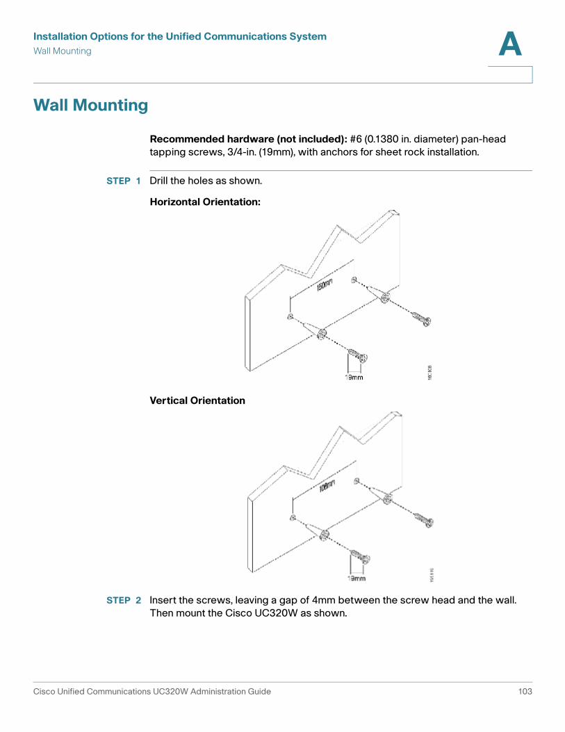
Installation Options for the Unified Communications System
Wall Mounting A
Wall Mounting
Recommended hardware (not included): #6 (0.1380 in. diameter) pan-head
tapping screws, 3/4-in. (19mm), with anchors for sheet rock installation.
STEP 1 Drill the holes as shown.
Horizontal Orientation:
Vertical Orientation
STEP 2 Insert the screws, leaving a gap of 4mm between the screw head and the wall.
Then mount the Cisco UC320W as shown.
Cisco Unified Communications UC320W Administration Guide 103
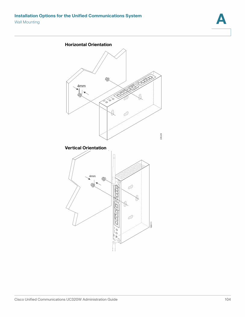
Installation Options for the Unified Communications System
Wall Mounting A
Horizontal Orientation
Vertical Orientation
1951
09
LINE (FXO)
PHONE
(FXS)
WAN/10/100/1000
LAN(10/100/1000)
LINE INLINE OUT
Power
122VDC
4
3
2
1
4
3
2
1
4mm
1951
11
4mm
LINE (FXO
)PH
ON
E(FXS)
WA
N/10/100/1000
LAN
(10/100/1000)LIN
E INLIN
E OU
TPow
er122VD
C
43
21
43
21
Cisco Unified Communications UC320W Administration Guide 104
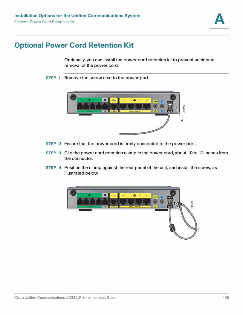
Installation Options for the Unified Communications System
Optional Power Cord Retention Kit A
Optional Power Cord Retention Kit
Optionally, you can install the power cord retention kit to prevent accidental
removal of the power cord.
STEP 1 Remove the screw next to the power port.
STEP 2 Ensure that the power cord is firmly connected to the power port.
STEP 3 Clip the power cord retention clamp to the power cord, about 10 to 12 inches from
the connector.
STEP 4 Position the clamp against the rear panel of the unit, and install the screw, as
illustrated below.
Power12VDCLAN (10/100/1000)WAN
(10/100/1000)
234 1 1234
LINE (FXO)PHONE(FXS)
LINEOUT
LINEIN 27
9961
Power12VDCLAN (10/100/1000)WAN
(10/100/1000)
234 1 1234
LINE (FXO)PHONE(FXS)
LINEOUT
LINEIN 27
9962
Cisco Unified Communications UC320W Administration Guide 105
B
Installing Phones and Attendant Consoles
This appendix provides information about the installation of IP phones and
attendant consoles, or “side cars.”
Refer to the following topics:
• Phone Connections, page 107
• Installing a Desk Stand (Optional), page 109
• Mounting a Phone to a Wall (Optional), page 110
• Connecting the Power, page 117
• Connecting a Phone to the Network, page 117
• Connecting a PC to a Phone (Optional), page 119
• Upgrading the Phone Firmware, page 119
• Connecting Attendant Consoles, page 119
Cisco Unified Communications UC320W Administration Guide 106
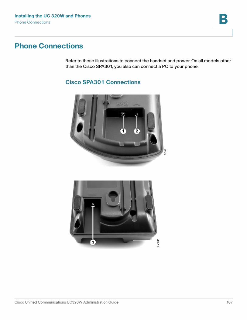
Installing the UC 320W and Phones
Phone Connections B
Phone Connections
Refer to these illustrations to connect the handset and power. On all models other
than the Cisco SPA301, you also can connect a PC to your phone.
Cisco SPA301 Connections
Cisco Unified Communications UC320W Administration Guide 107
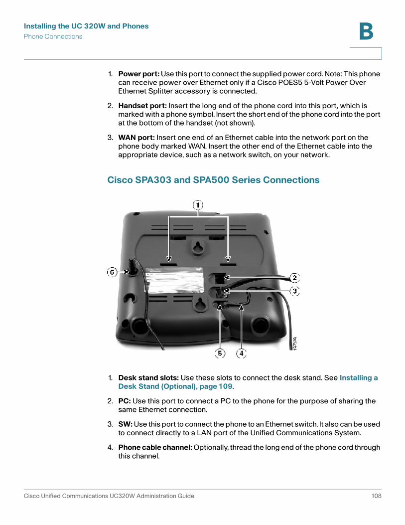
Installing the UC 320W and Phones
Phone Connections B
1. Power port: Use this port to connect the supplied power cord. Note: This phone can receive power over Ethernet only if a Cisco POES5 5-Volt Power Over Ethernet Splitter accessory is connected.
2. Handset port: Insert the long end of the phone cord into this port, which is marked with a phone symbol. Insert the short end of the phone cord into the port at the bottom of the handset (not shown).
3. WAN port: Insert one end of an Ethernet cable into the network port on the phone body marked WAN. Insert the other end of the Ethernet cable into the appropriate device, such as a network switch, on your network.
Cisco SPA303 and SPA500 Series Connections
1. Desk stand slots: Use these slots to connect the desk stand. See Installing a Desk Stand (Optional), page 109.
2. PC: Use this port to connect a PC to the phone for the purpose of sharing the same Ethernet connection.
3. SW: Use this port to connect the phone to an Ethernet switch. It also can be used to connect directly to a LAN port of the Unified Communications System.
4. Phone cable channel: Optionally, thread the long end of the phone cord through this channel.
Cisco Unified Communications UC320W Administration Guide 108
Installing the UC 320W and Phones
Installing a Desk Stand (Optional) B
5. Phone port: Use this port to connect the phone cord for the handset. Connect the other end of the phone cord into port on the bottom of the handset (not shown).
6. Power port: Use this port to connect the supplied power cord. Note: This phone can receive power over Ethernet only if a Cisco POES5 5-Volt Power Over Ethernet Splitter accessory is connected.
7. Side car Attachment features (not illustrated): See Connecting Attendant Consoles, page 119.
Installing a Desk Stand (Optional)
A desk stand is provided with each Cisco IP phone. The stand can be easily
attached or removed.
NOTE
• Do not attach the desk stand if you want to mount the phone to the wall. See
Mounting a Phone to a Wall (Optional), page 110.
• If you plan to attach a Cisco SPA500S attendant console, attach it before
attaching the desk stand. See Connecting Attendant Consoles, page 119.
STEP 1 Connect the phone stand by lining up the tabs on the stand with the slots on the
phone body.
STEP 2 Slide the bottom tabs into the lower slots on the phone body and lightly press
down on the stand. It should easily slide into the upper stand slots. Do not force.
Cisco Unified Communications UC320W Administration Guide 109

Installing the UC 320W and Phones
Mounting a Phone to a Wall (Optional) B
Mounting a Phone to a Wall (Optional)
NOTE This procedure requires an MB100 wall mount bracket kit (sold separately).
Attaching and Installing the Wall Mount Bracket Kit
Cisco Unified Communications UC320W Administration Guide 110
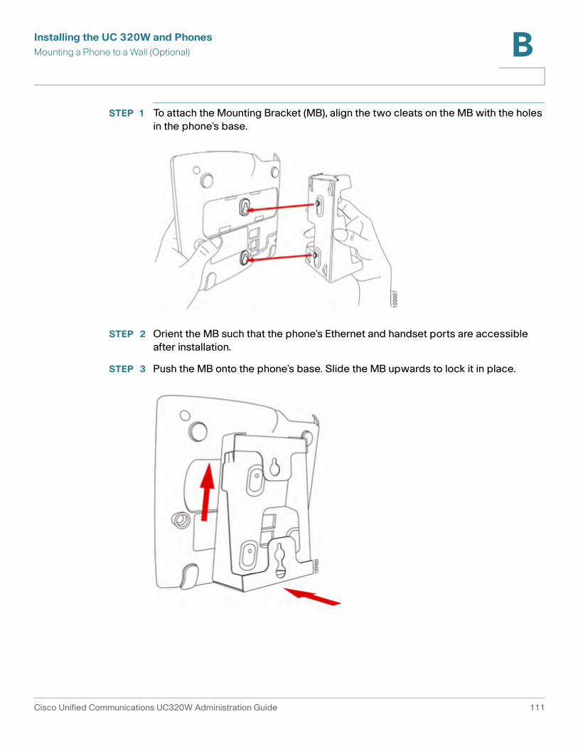
Installing the UC 320W and Phones
Mounting a Phone to a Wall (Optional) B
STEP 1 To attach the Mounting Bracket (MB), align the two cleats on the MB with the holes
in the phone’s base.
STEP 2 Orient the MB such that the phone’s Ethernet and handset ports are accessible
after installation.
STEP 3 Push the MB onto the phone’s base. Slide the MB upwards to lock it in place.
Cisco Unified Communications UC320W Administration Guide 111
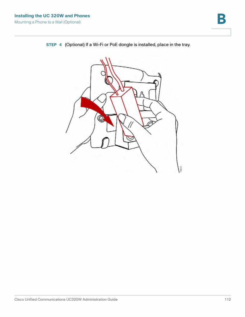
Installing the UC 320W and Phones
Mounting a Phone to a Wall (Optional) B
STEP 4 (Optional) If a Wi-Fi or PoE dongle is installed, place in the tray.
Cisco Unified Communications UC320W Administration Guide 112
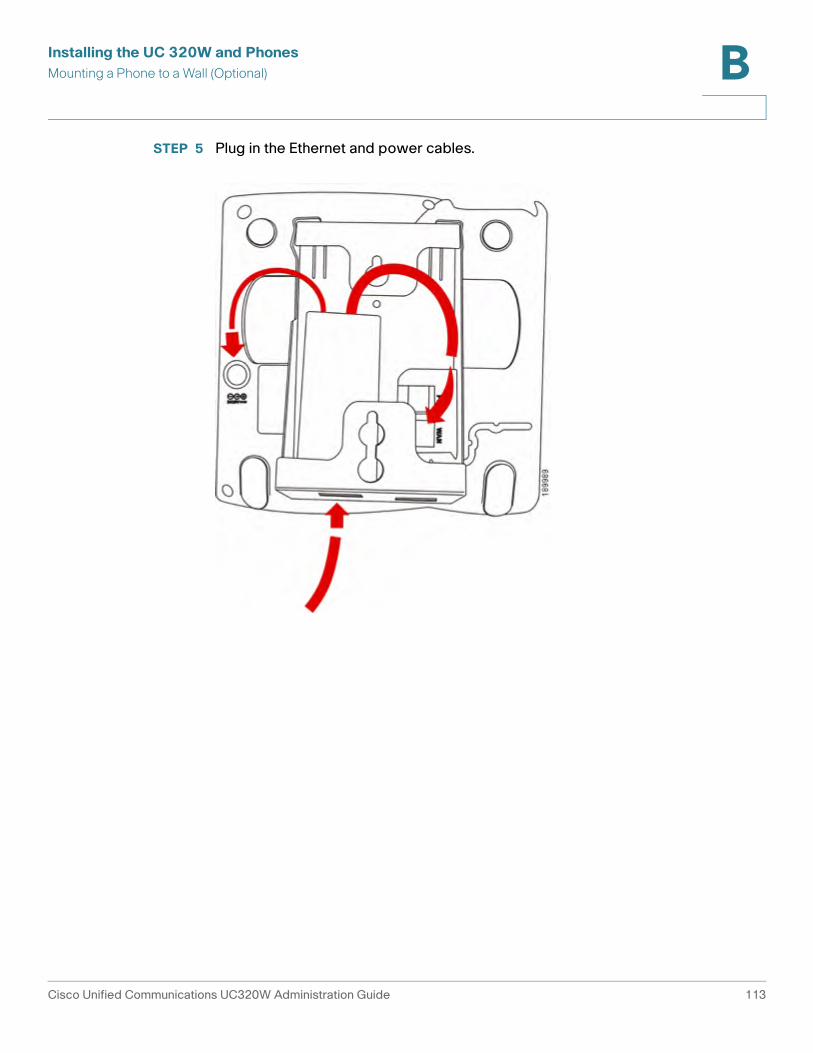
Installing the UC 320W and Phones
Mounting a Phone to a Wall (Optional) B
STEP 5 Plug in the Ethernet and power cables.
Cisco Unified Communications UC320W Administration Guide 113
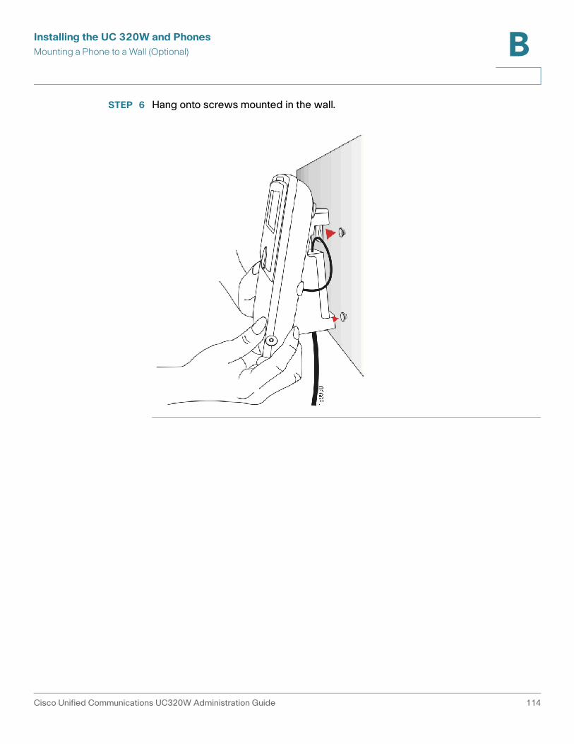
Installing the UC 320W and Phones
Mounting a Phone to a Wall (Optional) B
STEP 6 Hang onto screws mounted in the wall.
Cisco Unified Communications UC320W Administration Guide 114
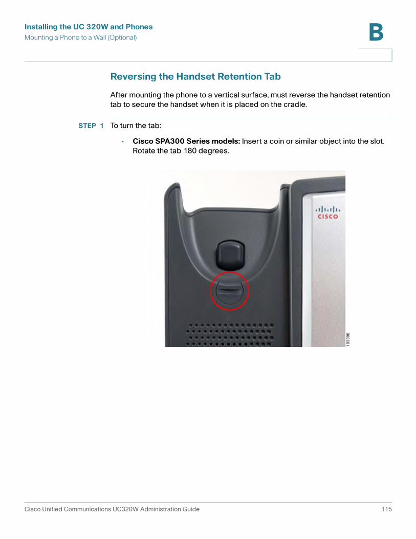
Installing the UC 320W and Phones
Mounting a Phone to a Wall (Optional) B
Reversing the Handset Retention Tab
After mounting the phone to a vertical surface, must reverse the handset retention
tab to secure the handset when it is placed on the cradle.
STEP 1 To turn the tab:
• Cisco SPA300 Series models: Insert a coin or similar object into the slot.
Rotate the tab 180 degrees.
Cisco Unified Communications UC320W Administration Guide 115
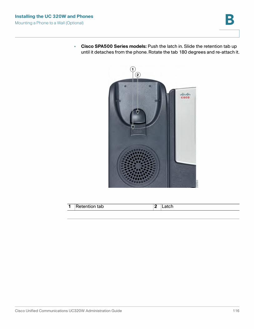
Installing the UC 320W and Phones
Mounting a Phone to a Wall (Optional) B
• Cisco SPA500 Series models: Push the latch in. Slide the retention tab up
until it detaches from the phone. Rotate the tab 180 degrees and re-attach it.
1 Retention tab 2 Latch
Cisco Unified Communications UC320W Administration Guide 116
Installing the UC 320W and Phones
Connecting the Power B
Connecting the Power
If you are using an external power source, insert one end of the power cord into an
outlet and insert the other end of the power cord into the power port on the phone
body.
Connecting a Phone to the Network
Connecting a Phone with an Ethernet Cable
STEP 1 Insert one end of the Ethernet cable into the network port on the phone body
marked “SW.”
STEP 2 Insert the other end of the Ethernet cable into a LAN port of the Cisco UC320W or
into a LAN port on an Ethernet switch.
NOTE On all models excepts Cisco SPA301, you can connect a PC to the phone’s second
Ethernet port (see Phone Connections, page 107). This port can be used when
the phone is connected the LAN with an Ethernet cable, but not when the phone is
operating wirelessly.
Connecting a Cisco SPA525G/G2 Model Phone to the UC320W Wireless Voice Network
If you enable the wireless voice network in the UC320W configuration utility, Cisco
SPA525 models can be used wirelessly. The wireless profile will be added to the
phone during the initial configuration.
IMPORTANT: For initial configuration of the phone, use an Ethernet cable. After
entering the settings, including the wireless network settings, apply the
configuration in the UC320W configuration utility. Wait for all devices to reboot and
reinitialize. At that point, you can begin this procedure.
Follow this procedure to verify that your phone is connected to the UC320W
wireless network. This procedure also explains how to connect to the network if
the wireless connection is not made automatically.
Cisco Unified Communications UC320W Administration Guide 117
Installing the UC 320W and Phones
Connecting a Phone to the Network B
STEP 1 If an Ethernet cable is connected to the phone, remove it and wait for the phone to
reboot. If an Ethernet connection is present on the phone, it is used instead of the
Wi-Fi connection.
STEP 2 Press the Setup button on your phone.
STEP 3 Scroll to Network Configuration and press Select.
STEP 4 In the Wi-Fi field, confirm that there is check mark to indicate that Wi-Fi is On. If the
check mark does not appear, press the left-arrow or right-arrow navigation button
to enter a check mark in the field.
STEP 5 Select Wireless Profile. The display should show that the phone is connected the
wireless voice network of your UC320W.
NOTE If the connection is not shown, complete the following tasks to connect to the
wireless network by using Wi-Fi Protected Setup.
a. Press the down-arrow navigation button to move the cursor to Wi-Fi
Configuration.
b. Press the right-arrow navigation button to open the Wi-Fi Configuration menu.
c. Select Wi-Fi Protected Setup. The Select the WPS Mode window appears.
d. Select Push Button Configuration. The Push Button Configuration instructions
appear.
e. On the front panel of the UC520W, press the Wi-Fi Protected Setup (WPS)
button.
f. On the phone, press Select. The phone displays a message: Connecting to AP.
The phone may reboot before the Wi-Fi connection is working.
NOTE The PC port is not supported in wireless operation. A PC can be connected to the
port only when an Ethernet cable is connected to the phone.
Cisco Unified Communications UC320W Administration Guide 118

Installing the UC 320W and Phones
Connecting a PC to a Phone (Optional) B
Connecting a PC to a Phone (Optional)
PC ports are not available on Cisco SPA300 Series phones.
A PC cannot be connected to Cisco SPA525 models that are connected to the
wireless network.
STEP 1 To provide network access to a PC, connect one end of an additional Ethernet
cable (not provided) to the PC port on the back of the phone body. See the
illustrations in the Phone Connections, page 107.
STEP 2 Connect the other end of the Ethernet cable to the network port on the PC.
After receiving power and network connectivity, the phone executes a boot-up
sequence. During this sequence, phones with screens display the Cisco logo and
then “Initializing Network.” All of the lights on the phone will flash.
After your phone is successfully connected to the network, it receives a basic
configuration. On all models except Cisco SPA501G, the time, date, extension
number, and softkeys appear on the display screen. On Cisco SPA501G, which
has no display screen, you should hear a dial tone when picking up the handset or
pressing the speakerphone button.
If the phone does not start, confirm your installation and connections. If these are
correct, try unplugging the phone and plugging it back in again.
Upgrading the Phone Firmware
Use the 320W Configuration Utility to upgrade the firmware for all components of the Unified Communications system.
Connecting Attendant Consoles
For extra line buttons, you can connect up to two Cisco SPA500S Attendant
Consoles to a Cisco SPA500 Series IP phone. Before you begin, you need the
following items:
• Cisco SPA500S Attendant Console
Cisco Unified Communications UC320W Administration Guide 119
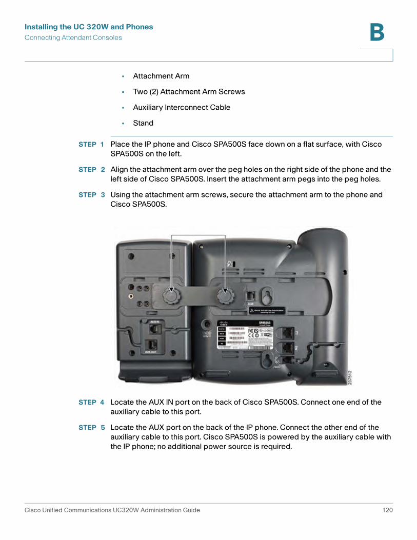
Installing the UC 320W and Phones
Connecting Attendant Consoles B
• Attachment Arm
• Two (2) Attachment Arm Screws
• Auxiliary Interconnect Cable
• Stand
STEP 1 Place the IP phone and Cisco SPA500S face down on a flat surface, with Cisco
SPA500S on the left.
STEP 2 Align the attachment arm over the peg holes on the right side of the phone and the
left side of Cisco SPA500S. Insert the attachment arm pegs into the peg holes.
STEP 3 Using the attachment arm screws, secure the attachment arm to the phone and
Cisco SPA500S.
STEP 4 Locate the AUX IN port on the back of Cisco SPA500S. Connect one end of the
auxiliary cable to this port.
STEP 5 Locate the AUX port on the back of the IP phone. Connect the other end of the
auxiliary cable to this port. Cisco SPA500S is powered by the auxiliary cable with
the IP phone; no additional power source is required.
Cisco Unified Communications UC320W Administration Guide 120
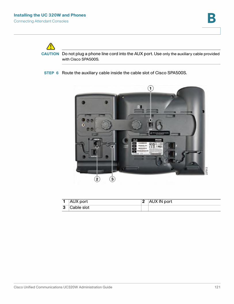
Installing the UC 320W and Phones
Connecting Attendant Consoles B
!CAUTION Do not plug a phone line cord into the AUX port. Use only the auxiliary cable provided
with Cisco SPA500S.
STEP 6 Route the auxiliary cable inside the cable slot of Cisco SPA500S.
1 AUX port 2 AUX IN port
3 Cable slot
Cisco Unified Communications UC320W Administration Guide 121
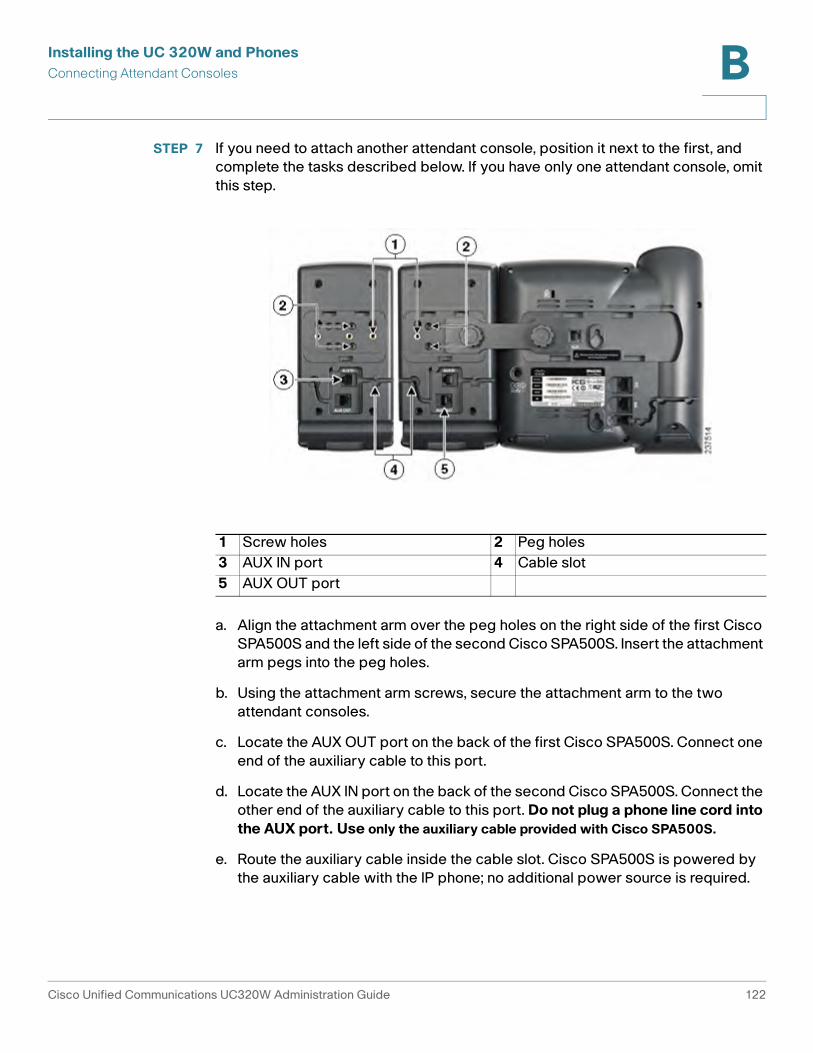
Installing the UC 320W and Phones
Connecting Attendant Consoles B
STEP 7 If you need to attach another attendant console, position it next to the first, and
complete the tasks described below. If you have only one attendant console, omit
this step.
a. Align the attachment arm over the peg holes on the right side of the first Cisco
SPA500S and the left side of the second Cisco SPA500S. Insert the attachment
arm pegs into the peg holes.
b. Using the attachment arm screws, secure the attachment arm to the two
attendant consoles.
c. Locate the AUX OUT port on the back of the first Cisco SPA500S. Connect one
end of the auxiliary cable to this port.
d. Locate the AUX IN port on the back of the second Cisco SPA500S. Connect the
other end of the auxiliary cable to this port. Do not plug a phone line cord into
the AUX port. Use only the auxiliary cable provided with Cisco SPA500S.
e. Route the auxiliary cable inside the cable slot. Cisco SPA500S is powered by
the auxiliary cable with the IP phone; no additional power source is required.
1 Screw holes 2 Peg holes
3 AUX IN port 4 Cable slot
5 AUX OUT port
Cisco Unified Communications UC320W Administration Guide 122
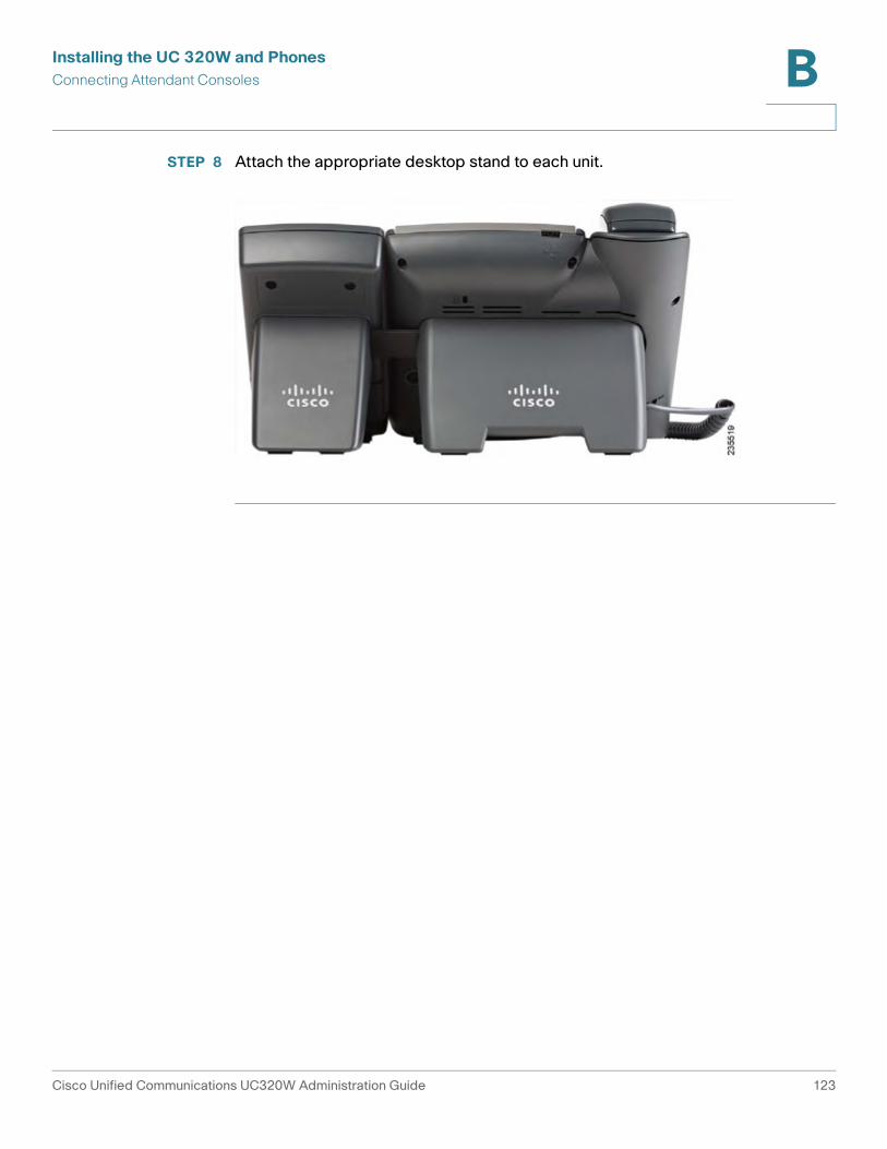
Installing the UC 320W and Phones
Connecting Attendant Consoles B
STEP 8 Attach the appropriate desktop stand to each unit.
Cisco Unified Communications UC320W Administration Guide 123
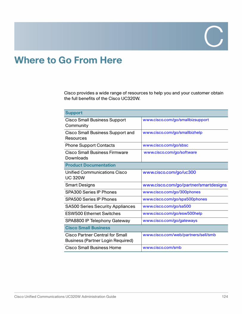
C
Cisco Unified Communications UC320W Administration Guide 124
Where to Go From Here
Cisco provides a wide range of resources to help you and your customer obtain
the full benefits of the Cisco UC320W.
Support
Cisco Small Business Support
Community
www.cisco.com/go/smallbizsupport
Cisco Small Business Support and
Resources
www.cisco.com/go/smallbizhelp
Phone Support Contacts www.cisco.com/go/sbsc
Cisco Small Business Firmware
Downloads
www.cisco.com/go/software
Product Documentation
Unified Communications Cisco
UC 320W
www.cisco.com/go/uc300
Smart Designs www.cisco.com/go/partner/smartdesigns
SPA300 Series IP Phones www.cisco.com/go/300phones
SPA500 Series IP Phones www.cisco.com/go/spa500phones
SA500 Series Security Appliances www.cisco.com/go/sa500
ESW500 Ethernet Switches www.cisco.com/go/esw500help
SPA8800 IP Telephony Gateway www.cisco.com/go/gateways
Cisco Small Business
Cisco Partner Central for Small
Business (Partner Login Required)
www.cisco.com/web/partners/sell/smb
Cisco Small Business Home www.cisco.com/smb