Embed Size (px)
Citation preview

Cisco Kinetic for CitiesUrban Mobility—Crowd Starter Solution Design and Implementation GuideSolution Overview
Urban areas across the world are experiencing a rapid growth in population size and density. Today, with less than two percent of world's landmass, cities are home to more than half of the world's population. This massive growth of population, along with constrained resources, is posing huge challenges to both city authorities and citizens. Cities consume two-thirds of the world's energy and account for more than 70% of CO2 emissions. All of these factors require solutions that offer huge opportunities for information technology.
In general, the demand for high resources coupled with resource constraints and the increasing need for safety and security call for the digital transformation of cities, popularly coined as Smart Cities. A Smart City is an urban area that uses different types of electronic data collection sensors to supply information for efficiently managing assets and resources.
Smart Cities' digitization programs span several domains including lighting, traffic, parking, safety and security, and environment. For more information about Smart Cities, refer to the following URLs:
http://www.c40.org/why_cities
http://edition.cnn.com/2007/TECH/12/31/eco.cities/
Cisco Kinetic for CitiesCisco Kinetic is a cloud-based platform that helps customers extract, compute, and move data from connected things to IoT applications in order to deliver better outcomes and services. More explicitly, it gets the right data to the right applications at the right time—across edge, private cloud, public cloud, and hybrid environments—while executing policies to enforce data ownership, privacy, security, and even data sovereignty laws.
Cisco Kinetic for Cities (CKC)1 is Cisco’s IoT solution for Smart Cities that addresses various city digitization programs. It brings policy-based control and automation to city infrastructure features, such as streetlights, parking sensors, traffic and crowd monitoring, environmental sensors, and video (CCTV) cameras. It is a powerful digital platform for aggregating, normalizing, and analyzing the wealth of community data from a myriad of intelligent sensors and city assets. The platform is generic and flexible in its ability to onboard any smart city solutions or digitization programs.
Cisco Kinetic for Cities Starter Solutions are bundles or packages that help customers to get started quickly with limited budgets. The Starter Solutions assist customers in achieving the following objectives:
Start small and quickly and then grow over time to full production-scale deployment.
Use pre-selected technology partners and fixed components, making it easy to deploy.
Achieve tangible business value two weeks after the physical installation.
1. CKC was formerly known as the Cisco Smart+Connected Digital Platform (or CDP)
1
Cisco Systems, Inc. www.cisco.com

Cisco Kinetic for Cities Urban Mobility—Crowd Starter Solution Design and Implementation Guide
Solution Overview
Get hardware/software/services from Cisco and third parties in a single package.
Obtain easy access in real time to the platform using a web-based graphical user interface.
Figure 1 shows the domains for the initial starter solution bundles.
Figure 1 Cisco Kinetic for Cities Starter Solutions
The CKC Golden Mile bundle is an aggregate bundle with all the capabilities and options of the combined, individual CKC domain-specific Starter Solutions.
Cisco Kinetic for Cities Starter Solutions Ordering InformationNote: The following information is only available to Cisco Channel Partners and Cisco personnel with a valid CCO (Cisco Connection Online) login. Customers and other interested parties should contact their local Cisco distributor or Cisco Account Manager for order information and details.
Detailed ordering information can be found in the CKC Starter Solutions Ordering Guide at:https://salesconnect.cisco.com/open.html?c=3ea6d960-10bb-49b8-ade0-9282a0762042
To order the CKC Starter Solutions using the Cisco Commerce Workspace (CCW), follow the instructions in the CKC Starter Solutions Order Guide and go to:https://apps.cisco.com/Commerce/home
Then follow the ordering guide guidance on how to search for the CKC Starter Solutions IDs:https://www.cisco.com/c/en/us/solutions/collateral/industry-solutions/guide-c07-740062.html#FindingsolutionIDs
Scope of this Cisco Reference DesignThis Cisco Reference Design (CRD) describes the design and implementation details for the Urban Mobility—Crowd (UMC), a subset of the Urban Mobility domain. The solution lab, test plan, and execution focus is set up based on the end-to-end CKC system architecture; however, the UMC Starter Solution is the sole focus for the solution evaluation.
Urban Mobility CrowdUMC provides analysis and reporting for crowd monitoring and its overall use case is location analytics for crowds. The goal for crowd location analytics is to understand visitor patterns, including crowd patterns across day/week/year and across locations. Possible business cases for this include the product/offering that gets higher user attention, effectiveness of a marketing campaign, staffing requirements for show room outlets spread across sites and across days, and the design of the customer loyalty program. For city officials, this gives an indication of probable crowd density patterns across the city to plan various services and allows them to see the heavily used and under used areas of the city.
Since the Urban Mobility—Crowd solution is based on Wi-Fi analytics, another important benefit of the solution is the provision of public Wi-Fi services, which can be further supported by the advertising services built into the Meraki Wi-Fi services and platform. This infrastructure can also be used to provide managed Wi-Fi services for city employees and nominated city workers (e.g., parking attendants). Since these are standard Cisco Meraki Wi-Fi capabilities, these elements of the solution are not covered in this design guide.
2

Cisco Kinetic for Cities Urban Mobility—Crowd Starter Solution Design and Implementation Guide
Solution Overview
UMC Solution Crowd Demographics and Example Use CasesThe CKC UMC starter solution addresses the following use cases:
Device count (Wi-Fi)—The system monitors Wi-Fi device count in real-time at each of the Wi-Fi Access Point (AP) locations. Additional description of the Wi-Fi device is covered later in End Devices, page 6. This indirectly indicates the crowd count trending at the AP location. This capability of monitoring crowd trend over a period of time enables several use cases, such as:
— Trigger alerts during overcrowding events.
— Derive crowd count trends during weekdays/weekends/ holidays, thus enabling the authority to appropriately staff the location and equip facilities.
— Forecast crowd count trend, thus plan for infrastructure upgrade.
Apart from this, several kinds of reports can be generated aiding city planning and management. Note that “device” and “client” are synonyms and the terms are used interchangeably in this document.
The real-time count statistics shown at each AP include:
— Total number of devices in the proximity of the given AP
— Total number of Wi-Fi devices connected/associated to the given AP
Dwell time—These are real-time statistics of the average time spent by the devices in the AP location. As discussed earlier this indirectly maps to the average dwell time of crowd/visitors of the location. Some example use cases enabled by this capability are identifying locations where visitors are spending higher time and identifying dwell time trends across days and locations. The details of these dwell time statistics include:
— Average dwell time of the devices in the AP location
— Total number of devices in the proximity of the given AP
Device count indicates how many people are in an area and/or have passed by recently (by default in the last 10 minutes). Dwell time indicates how much time people spend at different locations.
The UMC starter solution is based on Cisco’s Meraki Wi-Fi solution; however, the solution and use cases are partner- and technology-neutral and, outside of this starter solution, CKC can also support these use cases with Cisco’s Aironet and CMX solutions.
Note: Vendor/technology-specific terms such as Detected, Passer-By, Visitor, Probing, and Unconnected are not used. The above description of use cases is independent of BLE/Wi-Fi technology. However, Wi-Fi is shown in brackets indicating only that it is supported in the UMC Starter Solution.
Cisco Meraki Use Cases and UMC Crowd Demographics ComparisonNote that the use cases of Meraki do not map directly to CKC crowd demographics; rather, they complement each other. Meraki location tracking provides extensive location tracking capabilities including instantaneous counts at every location and crowd movement behavioral pattern, whereas CKC crowd demographics give location wise count and dwell time trend over a period (default 10 minutes). Apart from this, CKC empowers using the data for cross domain operations. Operators need to use the appropriate user interface (Meraki/CKC) based on the desired application. Table 1 maps similar features of Meraki and CKC UMC for a comparison.
3
Cisco Kinetic for Cities Urban Mobility—Crowd Starter Solution Design and Implementation Guide
Cisco Urban Mobility Crowd Unique Selling Points
Cisco Urban Mobility Crowd Unique Selling PointsThe unique selling points (USPs) for UMC include the following:
Detects both associated and probing Wi-Fi end devices. These types are described in End Devices, page 6.
No additional deployment considerations for location tracking (it uses standard public deployment Wi-Fi Meraki network)
Zero-touch Wi-Fi deployment, self-monitored, self-configured, and cloud managed; see the following URL:
— https://meraki.cisco.com/trust
Secured end-to-end network
Minimal cloud bandwidth requirement
Vendor/technology-independent data, views, reports normalization
Multi-domain/cross domain event correlation and policy definitions
Pay-as-you-grow model; pay only for services consumed
Scalable solution architecture
Scalable business model
Large partner integration base; Cisco-certified partner ecosystem
Table 1 Meraki Use Cases and CKC Crowd Demographics Mapping
Meraki Use Cases CKC Crowd Demographics
Proximity and Capture Rate:
Gives count of passer-by, visitors and connected devices
Shows capture-rate, how many passers-by are becoming visitors
Device Count:
Gives total count of devices (includes probing and connected) seen by an AP
Gives connected device count
Engagement:
Different durations of user engagement (5 min to 6+ hours)
Average visits
Dwell Time:
Gives average dwell time of all devices in a configurable window size (default 10 minutes)
Loyalty:
Visitor loyalty (First time, daily, weekly, occasional visits)
Daily average repeat rate
Not supported
Comparison:
Network wise comparison for visitor trends, repeat visit rate
Not supported
Cisco domain correlation:
Not supported
CKC supports cross domain correlation and policies. For example device count information of a location can be used to control the on/off state of street lights.
4

Cisco Kinetic for Cities Urban Mobility—Crowd Starter Solution Design and Implementation Guide
Cisco Kinetic for Cities UMC Starter Solution
Cisco Kinetic for Cities UMC Starter SolutionNote: The following information is only available to Cisco Channel Partners and Cisco personnel with a valid CCO (Cisco Connection Online) login. Customers and other interested parties should contact their local Cisco distributor or Cisco Account Manager for order information and details.
The Starter Solution description and BoM for all domains is available at the following URLs:
Overall Cisco Kinetic for Cities SalesConnect link is:
— https://salesconnect.cisco.com/#/program/PAGE-11391
Cisco Kinetic for Cities Starter Solutions SalesConnect link is:
— https://salesconnect.cisco.com/#/program/PAGE-11271
Technology Partners for UMCIn the Starter Solution, Cisco Meraki is the only technology partner for Urban Mobility Crowd for all geographic regions, as shown in Table 2.
CKC Licensing Models CKC Model—The digital platform will be deployed on a cloud owned by a Cisco certified cloud partner and will be
hosted and managed by Cisco.
On-premises Deployment Mode—The digital platform will be deployed on a data-center server or cloud managed by the customer. The initial deployment will be handled by the Cisco team and thereafter the customer will manage the digital platform on their cloud.
The starter solutions are only supported with the CKC Cloud-hosted deployment and licensing model.
For general deployments, the CKC platform offers the following subscription categories that customers may choose from based on what best meets their need:
Things as a Service (TaaS)—Base offering provides data from sensor assets from one vendor within one domain.
Domain as a Service (DaaS)—Normalized sensor data across vendors exposed to the platform as APIs.
Business as a Service (BaaS)—Normalized data across domains, enabling contextual relationships between two or more different domains; data also exposed to the platform as APIs.
The required software subscription SKUs (TAAS, DAAS, and BAAS for one year) are included in the respective starter solution BoMs.
Table 2 Geographic Regions where Meraki is the Only Technology Partner for UMC
US/ Canada EU UK ANZ IND ME LATAM Japan
Cisco Meraki
Yes Yes Yes Yes Yes Yes Yes Yes
5

Cisco Kinetic for Cities Urban Mobility—Crowd Starter Solution Design and Implementation Guide
System Architecture
System ArchitectureThis section describes the CKC UMC end-to-end system architecture, various building blocks, and architectural considerations.
End-to-End System ArchitectureFigure 2 shows the overall UMC system architecture, its layers, and various devices.
Figure 2 Urban Mobility Crowd System Architecture
End DevicesAny electronic device having Wi-Fi radio and Active Scanning enabled can be tracked for location analytics. Most devices are configured for Active Scanning because it offers lower power consumption. When Active Scanning is enabled, the Wi-Fi devices send probe requests at regular intervals containing the device MAC address (or a varying, random MAC address where MAC randomization is supported). The frequency/interval of probe requests can vary based on the state of the device (for example, asleep, standby, or associated), the model, the OS, any apps installed, the association state, and other factors. Apart from probe requests, 802.11 data frames from associated Wi-Fi devices can also be used to track devices.
Similarly, BLE scanners can track devices with a BLE-enabled radio, such as battery-based beacons, Apple iBeacons, and fitness monitors.
Note however that tracking of BLE devices is currently not supported with the UMC starter solution or the CKC Meraki Extension (integration) in general.
Access PointsAccess Points detect signals from Wi-Fi and BLE end devices and generate a presence signature. Based on the received signal strength from the devices, an AP can compute the device distance from itself. By combining the measured distance and the time spent in its proximity, APs can generate several location statistics. The recommended Access Point for the Urban Mobility Crowd deployment is the Meraki MR84:
https://meraki.cisco.com/lib/pdf/meraki_datasheet_MR84.pdf
6
Cisco Kinetic for Cities Urban Mobility—Crowd Starter Solution Design and Implementation Guide
System Architecture
However, other Meraki Access Points (for example, MR72 and MR66) with location-tracking capability can also be used for this purpose. MR84 APs location tracking happens both for 2.4 and 5GHz Wi-Fi devices and 2.4 GHz BLE devices.
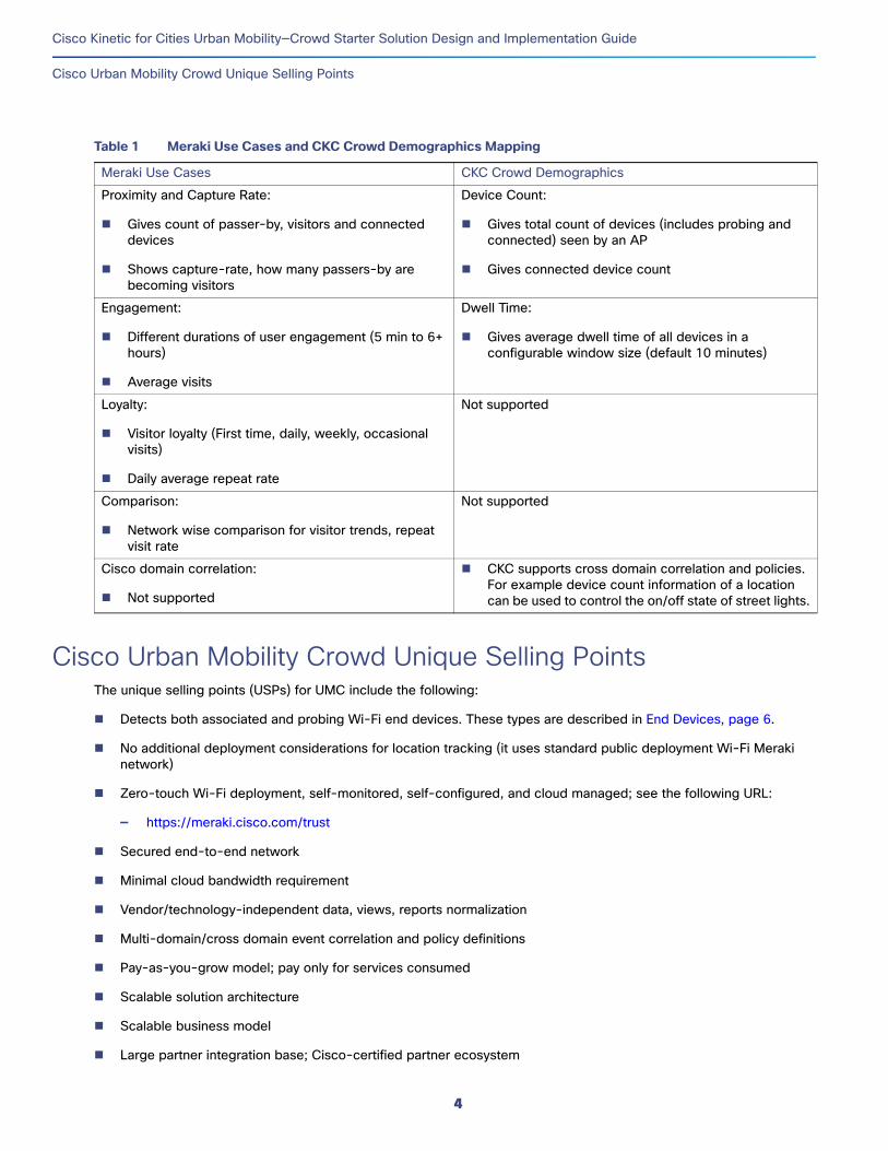
The Meraki APs can be deployed in mesh or non-mesh mode. The mesh networking functionality is automatic, self-configuring, self-healing, and available on all models of Meraki APs. A Meraki AP can be in either the Gateway or Repeater state. Gateway has a directly-wired connection to the Meraki Cloud. If an AP does not have a wired connection to the Meraki Cloud, it will automatically fail over to act as a repeater and look for a nearby gateway to reach the cloud. Both the Gateway and Repeater mode have location tracking capability. Figure 3 shows the multi-hop Meraki Wi-Fi network.
Figure 3 Multi-hop Wi-Fi Self-Configuring Mesh Network
No change is needed in the Meraki AP deployment method or density for supporting location analytics since existing deployments automatically collect the location analytics data.
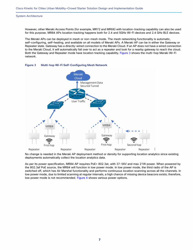
As per its power specification, MR84 AP requires PoE+ 802.3at, with 37-56V and max 21W power. When powered by the 802.3af PoE source, the MR84 will function in low power mode. In low power mode, the third radio of the AP is switched off, which has Air Marshal functionality and performs continuous location scanning across all the channels. In low power mode, due to limited scanning at regular intervals, a high chance of missing device beacons exists; therefore, low power mode is not recommended. Figure 4 shows various power options.
7
Cisco Kinetic for Cities Urban Mobility—Crowd Starter Solution Design and Implementation Guide
System Architecture
Figure 4 AP Powering Options
The following are salient specifications of the Meraki MR84 that support Location Tracking:
2.4 and 5GHz Wi-Fi device access
2.4 GHz BLE beacon and scanning radio
Dedicated radio for real-time Wireless Intrusion Detection and Prevention System (WIDS/WIPS) and location analytics (listens for Wi-Fi probe requests 24x7 on all channels)
Embedded location analytics and reporting (generates presence signature detecting probe requests and from 802.11 data frames)
IP67 environmental rating suitable for outdoor deployment
More information on the MR84 can be found at the following URL:
https://meraki.cisco.com/products/wireless/mr84
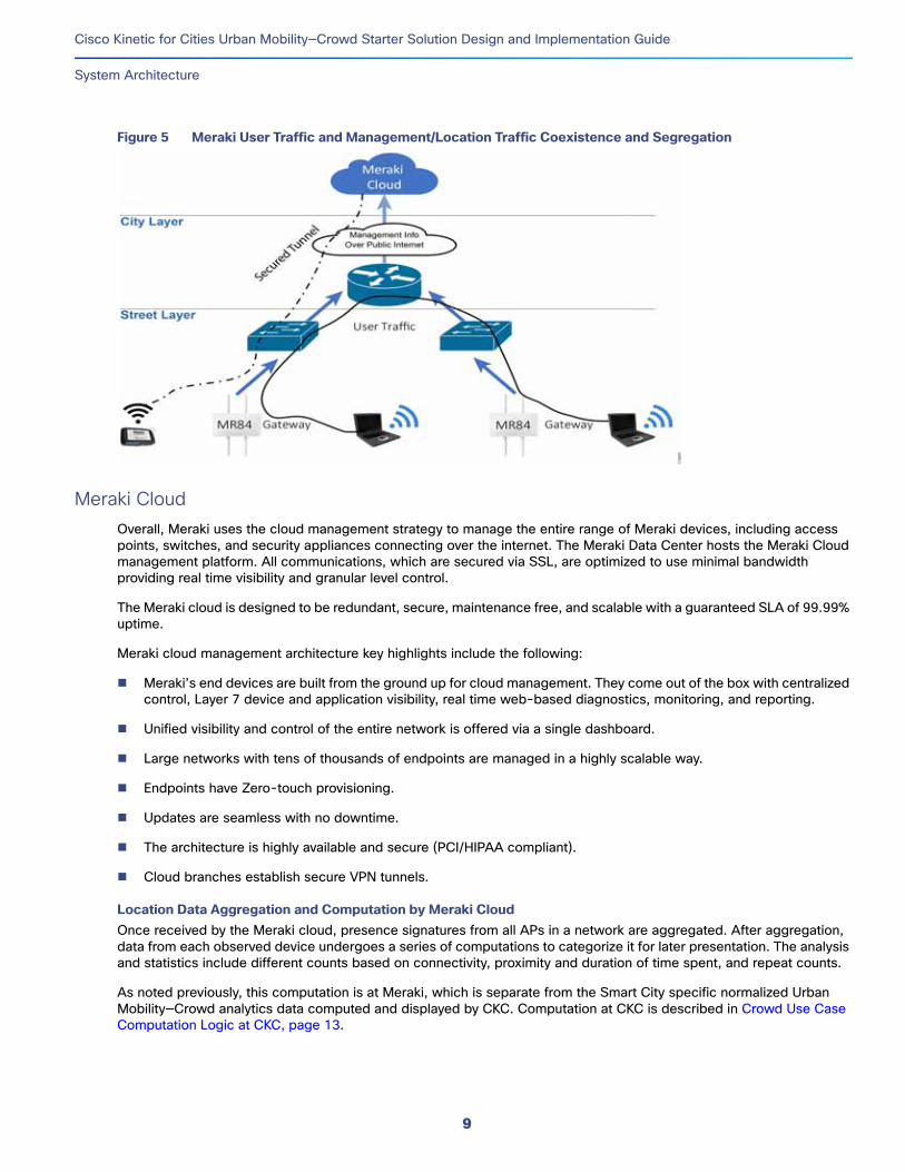
Backhaul NetworkThe solution is agnostic to backhaul connectivity between the Meraki AP and the Meraki Cloud. The MR84 has two 1Gbps Ethernet links. Link aggregation can be enabled, thus achieving 2Gbps throughput. The user traffic and management traffic are separated at the local switch/router level, as shown in Figure 5. Meraki Cloud centrally monitors and manages the APs. An out-of-band channel is used to carry control/management traffic to the cloud. User traffic/data does not flow through the cloud, but instead directly flows to its destination on the LAN or across the WAN. The control packets are carried to the cloud in a secured SSL channel and the control information is optimized and compressed so that the communication bandwidth needed remains around 1kbps. Since only the management data is sent to the cloud, the link remains less sensitive to latency and therefore can pass through the public Internet.
The APs monitor air signals to detect devices nearby and update the information every few seconds to the Meraki cloud through the backhaul network. Thus, when the backhaul network is down, the real-time location information cannot be updated. As the real-time monitoring of device location is the objective of location tracking, any stale location data collected at the AP during the backhaul link down is of little use.
Apart from bandwidth optimization, the out-of-band control plane improves scalability of the network by minimizing centralized controller bottlenecks and provides redundancy by means of high availability. The network continues to function even if the management traffic is interrupted. Security is improved since user traffic does not pass through the cloud.
8
Cisco Kinetic for Cities Urban Mobility—Crowd Starter Solution Design and Implementation Guide
System Architecture
Figure 5 Meraki User Traffic and Management/Location Traffic Coexistence and Segregation
Meraki CloudOverall, Meraki uses the cloud management strategy to manage the entire range of Meraki devices, including access points, switches, and security appliances connecting over the internet. The Meraki Data Center hosts the Meraki Cloud management platform. All communications, which are secured via SSL, are optimized to use minimal bandwidth providing real time visibility and granular level control.
The Meraki cloud is designed to be redundant, secure, maintenance free, and scalable with a guaranteed SLA of 99.99% uptime.
Meraki cloud management architecture key highlights include the following:
Meraki’s end devices are built from the ground up for cloud management. They come out of the box with centralized control, Layer 7 device and application visibility, real time web-based diagnostics, monitoring, and reporting.
Unified visibility and control of the entire network is offered via a single dashboard.
Large networks with tens of thousands of endpoints are managed in a highly scalable way.
Endpoints have Zero-touch provisioning.
Updates are seamless with no downtime.
The architecture is highly available and secure (PCI/HIPAA compliant).
Cloud branches establish secure VPN tunnels.
Location Data Aggregation and Computation by Meraki CloudOnce received by the Meraki cloud, presence signatures from all APs in a network are aggregated. After aggregation, data from each observed device undergoes a series of computations to categorize it for later presentation. The analysis and statistics include different counts based on connectivity, proximity and duration of time spent, and repeat counts.
As noted previously, this computation is at Meraki, which is separate from the Smart City specific normalized Urban Mobility—Crowd analytics data computed and displayed by CKC. Computation at CKC is described in Crowd Use Case Computation Logic at CKC, page 13.
9

Cisco Kinetic for Cities Urban Mobility—Crowd Starter Solution Design and Implementation Guide
System Architecture
References include the following:
https://meraki.cisco.com/trust#overview
https://meraki.cisco.com/lib/pdf/meraki_datasheet_cloud_management.pdf
Meraki DashboardThe Meraki dashboard provides a unified view of the entire network and all functionality in a single pane of glass view, including:
Network-wide monitoring and configuration of general functionality (such as devices, traffic, policies, alerts, provisioning, and security)
Wireless parameters monitoring and configuration (such as Maps, APs, RF, Wi-Fi, BLE, and Firewall)
Organization-wide monitoring and configuration (such as logs, location analytics, templates, firmware upgrades, licensing, inventory management, and network creation)
For more details on the location analytics feature supported by Meraki, refer to the following URL:
https://documentation.meraki.com/MR/Monitoring_and_Reporting/Location_Analytics
Meraki Northbound Interface (NBI)Location API/Scanning API—Cisco Meraki cloud exports/pushes raw data from the observed probe requests in real-time through a Northbound Interface (NBI) called location API/ Scanning API, which is depicted in Figure 6. Both Wi-Fi and BLE scanned data are exported/pushed and Http and Https NBI interfaces are supported. The operator can enable/disable Scanning API. JavaScript Object Notation (JSON) is used for data formatting. Up to four destinations can be specified as northbound receivers. The JSON posts are batched per AP and typically pushed once a minute.
Figure 6 Meraki Scanning API
Table 3 lists the key attributes of the Scanning/Location API version 2.0 structure.
10

Cisco Kinetic for Cities Urban Mobility—Crowd Starter Solution Design and Implementation Guide
System Architecture
Using the physical placement of the AP on the map location of the device (lat, lng, unc, x, and y) is estimated. The location, which depends on several factors, is a best effort location estimation.
Table 3 Meraki Scanning API Structure
Attribute Name DescriptionBoth (Wi-Fi & BLE)/Only Wi-Fi
apMac MAC address of the observing AP Both
apTags Tags applied to the AP Both
apFloors List of floor plans on which this AP appears Both
Client List (repeated for each client)
List of clients, whose probe requests were observed since the previous push
Both
{clientMac Client MAC address Both
client-IPv4 Client IPv4 address and hostname (if available) Only Wi-Fi
client-IPv6 Client IPv6 address and hostname (if available) Only Wi-Fi
seenTime Observation time in UTC Both
seenEpoch Observation time in seconds since the UNIX epoch Both
Ssid Client SSID name; null if the device is not connected Only Wi-Fi
Rssi Client RSSI as seen by AP Both
location {lat, lng, unc, x, y} Client geolocation; null if location could not be determined
Latitude, longitude, uncertainty in meters
x and y offsets for each floorplan
Both
11

Cisco Kinetic for Cities Urban Mobility—Crowd Starter Solution Design and Implementation Guide
System Architecture
Figure 7 Sample NBI Output Captured at the Receiver End
Dashboard API:Dashboard API is a RESTful API using HTTPS and JSON for data serialization. The operator can control access to the dashboard API with secret keys. Literally, any configurations can be queried/added/deleted/updated with the Dashboard API by an external application having the desired API security keys.
Some examples include manage (list, add, and update) organizations and their associated configurations, manage networks in an organization, manage devices (AP, switches) of a network, and manage SSIDs.
Https GET is used for all read requests and Https PUT is used for all write requests. In either case, several parameters are used. Refer to the Meraki API documentation at the following URL for details:
https://documentation.meraki.com/zGeneral_Administration/Other_Topics/The_Cisco_Meraki_Dashboard_API
12

Cisco Kinetic for Cities Urban Mobility—Crowd Starter Solution Design and Implementation Guide
System Architecture
CKC Urban Mobility Crowd DomainCKC provides appropriate extensions/connectors to interface with the Meraki Cloud NBI and queries the Meraki NB API at regular intervals to fetch the infrastructure information (such as the list of APs and their attributes such as identity, name, and geolocations).
The CKC Meraki extension listens to location update posts from Meraki. Information from these location updates is used to calculate and populate the crowd statistics in CKC.
The UMC domain at CKC, which is vendor- and technology-agnostic, supports the following demographics:
Total device count at each AP
Connected device count at each AP
Average dwell time of all devices at each AP
Crowd Use Case Computation Logic at CKCThe CKC system maintains and implements the compute logic for the following data structures:
1. System maintains current Wi-Fi device list per AP; this list includes both Connected and Probing devices.
2. When a new device (not present in the list) is seen, its record is added to the list with firstSeen time and lastSeen time both set to current time.
3. Every subsequent time when the same device is seen, its lastSeen time is updated to the current time.
4. A device is deleted from the list if it is not seen for more than 10 minutes (configurable by Cisco Cloud Ops) from its own lastSeen time.
5. Device records in the list are unique per AP.
Total device count computation per APCount of all [Connected + Probing] Wi-Fi devices seen by each AP during previous 10 minutes.
Cumulative device count computationCumulative “Total count” of all APs in the entire Tenant. This can be viewed by zooming out on the MapView.
Connected count computation per APCount of Connected Wi-Fi devices seen by each AP during previous 10 minutes
Dwell time computation per APAverage dwell time of an AP is the average time spent by all devices who visited the AP location during last 10 minutes
DwellTime for a single device = lastSeen - firstSeen
Average DwellTime for all [Connected + Probing] devices per AP = Sum of DwellTime of all devices [Connected + Probing] per AP / total number of devices [Connected + Probing] per AP
DwellTime unit: Minutes
Timing sequenceCurrent Wi-Fi device list is updated as and when push notification received from partner system and when any device times out with no updates for 10 minutes.
Total Count, Connected Count, and DwellTime are computed once in every 60 seconds.
CKC UI is refreshed with the latest statistics values every 2 minutes.
13

Cisco Kinetic for Cities Urban Mobility—Crowd Starter Solution Design and Implementation Guide
System Architecture
Regions and Geo-PositioningMenu-driven provisioning can be used to select and navigate to a desired region or city based on access rights. The list of APs in the selected region are shown on the map. The above use cases (statistics) can then be viewed for each AP in the selected region.
History ReportViewing average dwell time report for a given duration (start date and time and end date and time) is supported.
Policy, Events, and Alerts SupportWhile no default policies are defined for UMC, custom policies can be defined (e.g., events such as overcrowding that can trigger specific actions). No system-defined alerts are supported in the Starter Solution.
Wi-Fi Wireless Last Mile ConsiderationsLocation analytics require no change to the Meraki-recommended Wi-Fi deployment in terms of density, coverage distance, bandwidth computation, mesh, or survey.
The following summarizes the Meraki Wi-Fi deployment recommendations related to location analytics:
1. It is desirable to use as many gateway access points as possible to maximize overall network performance and reliability.
2. Non-mesh is preferred; if mesh is needed, then try limiting mesh depth to 1 hop since the deeper the mesh, the greater the chances of congestion and missing packets.
3. Limit the repeaters attached to a gateway to a maximum of 2. The recommendation is to have multiple failover paths—at least three strong neighbors for each repeater.
4. All use cases will function normally both with Mesh and Non-Mesh APs (gateway, repeater, and standalone AP). Refer to Table 3.
5. Although theoretically up to 255 devices can be associated to a single AP, the practical limits will be much lower. The number of APs needed to cover an area depends on several factors, such as type of applications, number of devices, supported Wi-Fi standard, and number of streams supported. Refer to the Meraki Wi-Fi Deployment Guide for deployment details.
6. Typically, all devices within 100 feet Line of Sight (LOS) range result in a seen device event from Meraki AP.
7. All use cases listed in Table 4 can coexist with the regular uplink and downlink LAN/user traffic. In other words, user traffic has no bearing on applicability and accuracy of use cases.
References:
https://documentation.meraki.com/MR/Deployment_Guides/High_Density_Wi-Fi_Deployment_Guide_(CVD)
Table 4 Use Case Validity with Mesh and Non-Mesh APs
Non-Mesh AP Single-Hop AP Multi-Hop AP
Wi-Fi associated and un-associated Device Count True True True
BLE device count True True True
Dwell Time for Wi-Fi and BLE devices True True True
14
Cisco Kinetic for Cities Urban Mobility—Crowd Starter Solution Design and Implementation Guide
System Architecture
BLE Last Mile ConsiderationsMeraki APs such as the MR84 with an integrated BLE radio can detect and locate nearby BLE devices. As is the case with Wi-Fi, no special recommendations exist for Meraki AP deployment to detect Bluetooth beacons for location analytics.
Typically, all BLE devices within 100 feet LOS range result in a seen device event from the Meraki AP.
Backhaul Network ConsiderationsThe solution is transparent to the backhaul connectivity, which could be a private or public network connecting to the Meraki cloud hosted in the Internet, as shown in Figure 2. The CKC Starter Solution explicitly states: “Network Backhaul/Internet connectivity needs to be provided by the customer.”
The backhaul network should give provisions for splitting management and user traffic locally. User traffic should be routed locally and management traffic should be forwarded to the Meraki cloud.
In cases of a greenfield deployment or while portions of network are being designed from scratch, the “DNA for Cities” network architecture can be followed as a reference architecture/guideline, as described in the following URL:
https://salesconnect.cisco.com/open.html?c=c4b7dbab-4f5b-42a3-a087-2d55ea44743b
This architecture is designed to support Smart City use cases with considerations for end-to-end security, scalability, high availability, QoS, and network management. It covers the design of the last mile access at the street layer, backhaul connectivity at the city layer, and the Network Operations Center (NOC) at the data center layers. This network architecture is designed with the vision of supporting numerous smart city services today and expanding it in the future for new applications and services.
End-to-End Security ProvisionMeraki protects the device's Wi-Fi access with security protocols such as Wi-Fi Protected Access 2 (WPA2). However, Wi-Fi Probe requests are unencrypted and not authenticated. Thus, Mac spoofing is possible and an attacker can affect the user-count and dwell time computations. However, this will not affect the core functionality of the network, the Wi-Fi data traffic.
All management communications from the AP to the Meraki Cloud are protected by being tunneled over SSL, which is auto-enabled. Separate VLANs can be used to segregate user traffic and management traffic. All user traffic can be locally routed with desired security configurations.
A secured communication https should be used between the Meraki Cloud and the third-party receiver such as CKC Cloud. While using HTTPS, the endpoint must have a valid certificate signed by a valid public Certificate Authority. If a certificate is not signed by a recognized CA, is expired, revoked, or otherwise invalid, a session cannot be established to allow the incoming POST. In some circumstances, a signed certificate can be valid but still unrecognized if signed by an intermediary CA unknown to Dashboard. For this reason, the full CA chain should be included when using HTTPS.
Meraki validates the receiver, asking for the validator string. Similarly, the receiver validates the post messages from Meraki by verifying the secure string in each post message.
Communication between and the CKC cloud and third-party apps/mobile apps are authenticated with OAuth 2 tokens and the channel is protected using https.
The architecture related to user-traffic routing, scaling, security, etc. are not part of the scope of this document. Refer to Meraki documentation for more information.
15

Cisco Kinetic for Cities Urban Mobility—Crowd Starter Solution Design and Implementation Guide
Privacy Protection
Architectural Best PracticesArchitectural best practices for location tracking include the following:
1. Avoid low power mode for APs and ensure availability of 802.3at power. In low power mode, Air Marshal functionality and dedicated radio for probe request scanning are disabled.
2. Use the secured channel https between the Meraki Cloud and CKC cloud.
3. Use the secured channel https between the CKC Cloud and third-party apps.
4. Preferably, no more than one hop wireless mesh should exist, as per Meraki wireless deployment best practice guideline.
5. In order to minimize propagation delay and resultant timeouts/authentication failures, the CKC cloud instance and the Meraki cloud instance should be hosted in the same geographic region.
Privacy ProtectionTracking location and movements naturally raises privacy concerns for the users/citizens. Privacy is protection is ensured both at Meraki and CKC.
Privacy Protection at MerakiThe Meraki solution ensures privacy. The MAC address in the location information is the only uniquely identifiable element and it is anonymized in an irreversible manner before storing in the database. The original MAC produces a SHA1 hash MAC address, the result is truncated to 4 bytes, and the resultant address is stored. SHA1 is a one-way cryptography function that ensures the irreversibility of the process.
Meraki provides a global opt-out feature for any user to register their MAC address, after which that MAC address will be undetectable for location tracking purposes and exporting via Scanning API.
Devices running OS that automatically generate random Wi-Fi MAC addresses, such as Apple iOS 8, cannot be uniquely tracked.
Apart from this, any user can disable/switch-off Wi-Fi and BLE on their devices so that they cannot be tracked by this technology.
Scanning API exports raw MAC address to specified third-party receivers; however, no customer identity or customer contact details are exposed.
Privacy Protection at CKCPrivacy protection at CKC ensures similar privacy. No device MAC address is stored in the persistent database. Device MAC addresses, which are seen at an AP, are cached temporarily at CKC and then are purged from the cache once the device departs from an AP location for more than a few minutes (~10 minutes). Also, this cache is an internal structure of CKC, which is never exposed through any interface and neither the device traverse path nor the device identity can be obtained from CKC.
16
Cisco Kinetic for Cities Urban Mobility—Crowd Starter Solution Design and Implementation Guide
Performance Measures
Performance MeasuresThis section describes several performance considerations/measurements for the end-to-end UMC system.
Time Taken to Get a Change Detected (Count/Dwell Time)
Figure 8 Location Information Propagation Delay
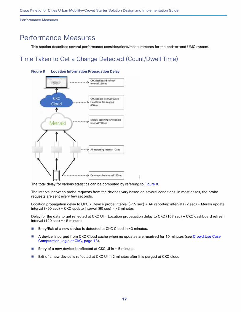
The total delay for various statistics can be computed by referring to Figure 8.
The interval between probe requests from the devices vary based on several conditions. In most cases, the probe requests are sent every few seconds.
Location propagation delay to CKC = Device probe interval (~15 sec) + AP reporting interval (~2 sec) + Meraki update interval (~90 sec) + CKC update interval (60 sec) = ~3 minutes
Delay for the data to get reflected at CKC UI = Location propagation delay to CKC (167 sec) + CKC dashboard refresh interval (120 sec) = ~5 minutes
Entry/Exit of a new device is detected at CKC Cloud in ~3 minutes.
A device is purged from CKC Cloud cache when no updates are received for 10 minutes (see Crowd Use Case Computation Logic at CKC, page 13).
Entry of a new device is reflected at CKC UI in ~ 5 minutes.
Exit of a new device is reflected at CKC UI in 2 minutes after it is purged at CKC cloud.
17

Cisco Kinetic for Cities Urban Mobility—Crowd Starter Solution Design and Implementation Guide
QoS in the Last Mile and in the Backhaul
One Year Record Storage Space RequirementThe CKC computes several demographics, which are stored in a persistent database. The unique records for the devices seen during the previous 10 minutes are stored in a cache. Assuming that the number of devices seen during previous 10 minutes in the vicinity of a AP does not exceed a few hundred, the total cache requirement for this is limited. Similarly, the storage needed to record statistics, which are computed every 60 seconds, is minimum.
Bandwidth Considerations and Computations for the Use Case TrafficAs mentioned earlier, the bandwidth requirement for updating the management information between the Meraki AP and the Meraki cloud is limited due to high compression. Typically, this management bandwidth requirement is 1KB.
QoS in the Last Mile and in the BackhaulWi-Fi Probe requests and BLE beacons from the devices are broadcasted on available channels with best effort. Management information from the Meraki AP to the Meraki cloud is sent on the public Internet with best effort marking (CS0). However, the control/management traffic from the APs should be marked with high priority to take advantage of QoS treatment en route. The recommendation from Cisco CVD 3,0 should be followed for QoS treatment of control/management traffic. By default Meraki APs mark control/management traffic as best effort CS0. The uplink switch receiving traffic from Meraki AP should mark all traffic on the control/management VLAN as high priority (CS6 - network control) at the ingress and configure high priority queueing at egress with guaranteed bandwidth allocation. As recommended in Cisco CVD 3.0, 2% of available uplink bandwidth can be reserved for control/management traffic. For example this translates to 20Mbps on a 1Gbps uplink.
The Http/Https POST from the Meraki Cloud to the third-party receiver is also best effort. Therefore, in general end-to-end from Meraki AP to CKC it is best effort delivery.
However, considering that devices send probe requests and data packets repeatedly, a high probability exists that the AP will receive them. The AP compresses the management information into very low bitrate 1Kbps, which increases the chances for its quick delivery. Since the Http post is TCP transmission, delivery is guaranteed.
All data at the AP is discarded when the cloud link is down; similarly, data at the Meraki NBI is discarded when the third-party receiver is not reachable or down, thereby avoiding stale data. However, this can result in a loss of location updates. CKC purges old and stale records if no updates are received for more than 10 minutes, thus maintaining data sanctity over a long period.
18

Cisco Kinetic for Cities Urban Mobility—Crowd Starter Solution Design and Implementation Guide
Message Flow Diagrams
Message Flow DiagramsFigure 9 shows the message flow between the Meraki cloud and the CKC server. Meraki authenticates the CKC server with a validation token and the CKC server authenticates Meraki posts with a secret. The NB interface can be http/https. Integration of CKC with Meraki Wireless Networks, page 41 elaborates the Meraki NBI configuration.
Figure 9 NBI Message Flow Diagram
19

Cisco Kinetic for Cities Urban Mobility—Crowd Starter Solution Design and Implementation Guide
Solution Components
Solution Components
Cisco ComponentsTable 5 shows the Cisco products used in CKC UMC Starter solution.
Third-Party ComponentsNo third-party components are used in the CKC UMC Starter Solution.
Cisco Kinetic for Cities (CKC) PlatformCisco CKC is a centralized integrated Internet of Things (IoT) platform for City Infrastructure and Services management. A multitude of vendors and solution providers often provide city infrastructure such as streetlights, parking lots, safety and security infrastructure, waste management, and environmental monitoring. CKC, as a centralized platform, interfaces with these vendors and solution providers and provides a uniform vendor-neutral cross-domain monitoring and management system.
Each solution domain consists of a range of sensors, a secured interface to communicate with the sensors, a mechanism to collect and collate information at a central location, and a central information events and policy management system.
The core functionality of the CKC platform includes:
1. Interface to multi-domain, multi-vendor, multi-technology, multi-interface sensors, devices, and apps.
2. Domain wise data normalization to a standard data model.
3. Monitoring and controlling of the derived information using the CKC Dashboard and other CKC apps (including third-party applications and analytics apps integrated with CKC and CKC Mobile apps).
Table 5 Cisco Components
Cisco Product Model and Version Description
Meraki Access Point MR84-HW
MR 25.9 and later (auto upgraded by Meraki Cloud)
Dual-band 802.11ac Wave 2 access point with separate radios dedicated to security, RF management, and Bluetooth.
Meraki Multigigabit
802.3at POE Injector
MA-INJ-5-XX (where XX stands for US/EU/UK/AU)
802.3at Power over Ethernet Injector.
Input power source specifications vary across regions. Customers need to choose a suitable PoE injector according to their location of deployment.
Meraki Cloud 2018 Version (auto-upgraded cloud version)
Cloud Management
CKC Cloud CKC version 4.0 and associated activation licenses
Cisco Kinetic for Cities
CKC Location Analytics as-a-service
Service license for CKC 4.0 Location Analytics Module
CDP Location Analytics Business API as-a-service
Service license for CKC 4.0 Location Analytics API
20

Cisco Kinetic for Cities Urban Mobility—Crowd Starter Solution Design and Implementation Guide
Cisco Kinetic for Cities (CKC) Platform
4. A platform for intra-domain and cross-domain correlation and policies.
5. Normalized data models exposed via Northbound APIs to business apps.
Cisco CKC High-Level Solution ArchitectureFigure 10 shows the high-level solution architecture of CKC. The building blocks include:
Various domain interfaces
A real-time engine to collect, normalize, time-series, and store data
Domain/vertical applications
Dashboard
Mobile apps and NBI to third-party apps.
Figure 10 Cisco Kinetic for Cities Solution Architecture
Further details and descriptions of the Cisco Kinetic for Cities 4.0 (CKC 4.0) solution and architecture can be found in the CKC 4.0 Business Decision Maker (BDM) presentation at the following URL:
Cisco Kinetic for Cities Urban Mobility BDM presentation:https://salesconnect.cisco.com/#/content-detail/fc093f72-bec4-491c-97a7-3975d676dafd
Note: The information above is only available to Cisco Channel Partners and Cisco personnel with a valid CCO (Cisco Connection Online) login. Customers and other interested parties should contact their local Cisco distributor or Cisco Account Manager for order information and details.
Cisco Kinetic for Cities Salient FeaturesThe salient features of the CKC solution include:
1. City-wide solution for multi-domain applications
2. Wide range of supported domains
21
Cisco Kinetic for Cities Urban Mobility—Crowd Starter Solution Design and Implementation Guide
Cisco Kinetic for Cities (CKC) Platform
3. Large number of off-the-shelf partner integrations for each domain, covering various geographies across the world
4. Partner and technology-independent normalized information model across the domain
5. Intra- and cross-domain event correlation and policy enforcement
6. Cross-domain policy-based automation
7. Highly scalable architecture, including compute, data storage, and network capability
8. Cloud-based deployment model
9. Support for user-friendly and customizable dashboards and third-party apps
10. NB API exposing both real-time and historical information
11. Out of the box and customizable reports
Tenants, Regions, Domains, and Access Control
TenantsA tenant is typically a city managed by a customer who is given access to the different infrastructures of the tenant based on the license.
Based on the request from the customer for specific City/Tenant with associated geographic locations, the Cisco Cloud Ops team provisions the same.
Defining Regions within a TenantThe administrator can define multiple sub-regions within the Tenant’s overall region (that is, City). A sub-region is any random area, overlapping/non-overlapping, within the parent region. A user can be assigned with one or more sub-regions, as shown in Figure 11.
Multi-DomainEach tenant is provisioned with a set of domains, as per the customer requirement, controlled by the customer license.
Assume a multi-tenant customer with two tenants: tenant-1 and tenant-2. As per license, the customer can have different domains for different tenants.
For example:
Domain-1 (Only Lighting) can be configured for tenant-1.
Domain-1 and Domain-2 (Lighting and S&S) can be configured for tenant-2.
CKC Users and Role-based Access Control (RBAC)CKC is a multi-user and multi-role platform in which multiple users and multiple roles can be created. Roles are groups with a variety of access permissions. Each user can be assigned a set of one or more roles. Broadly speaking, roles have two major categories: operators and administrators.
Operators have access to operational functionality. Operations are grouped by domains and each domain has an operations group, for example Parking Operator, Lighting Operator, Environment Operator, and Safety and Security Operator.
22

Cisco Kinetic for Cities Urban Mobility—Crowd Starter Solution Design and Implementation Guide
Cisco Kinetic for Cities (CKC) Platform
In addition to the functionality of the operator, administrators have rights for administrative functionality such as managing users, assigning roles to users, enabling policy modules, and assigning regions to users. These operator and administrator groups are defined by Cisco Cloud Ops.
Each user can be assigned with one more roles/groups and one or more regions/sub-regions, as shown in Figure 11.
If one or more sub-regions under a parent region are assigned to a user, the sub-regions (and not the parent region) appear in the drop-down menu.
If a parent region is assigned and no sub-regions are assigned under the parent region, then the parent region appears in a drop-down menu in the region section.
Figure 11 Users and Role Based Access Control (RBAC)
For Figure 11, which illustrates the flexibility of any user being assigned to any role(s) for any region(s), users are described below:
User-1 is an admin user having access to Sub Region-1 for all operator functionality.
User-2 is a parking operator for Sub Region-1.
User-3 is a parking operator for Sub Region-2.
User-4 is a multi-domain operator managing lighting and S&S for Sub Region-1 and Sub-Region-2.
After logging in, users can view the dashboard. From the user's access-dependent menus, which display in the dashboard, they can select a region from the allowed list of regions to monitor and perform desired operations.
All regions assigned to a user are within a single Tenant. Therefore, no user can access any kind of data across the tenants.
To manage the access permissions, the Cisco Cloud Ops team creates an initial set of logins. The CKC Hosting Partner or Customer, using an admin login having user-management permission, can then add subsequent users.
The combination of the above capabilities provides RBAC, with “Role” definitions based on the User Group to which a user belongs.
23

Cisco Kinetic for Cities Urban Mobility—Crowd Starter Solution Design and Implementation Guide
Cisco Kinetic for Cities (CKC) Platform
User management can also be done through NB integration. User account creation, associating user account to a group and set of locations, can all be done using appropriate NB API.
See CKC Northbound API Description, page 27 for a detailed description of NB interface and operations.
Portal TabsThe CKC portal provides a multi-tab interface. Upon login, a user can view the CKC portal with tabs and menus based on their access rights discussed earlier. A quick access to a summary view of overall system status and frequently viewed infrastructure is provided. Various prominent tabs and their purpose are described below:
Regions—A drop-down menu that displays various regions within the tenant for which the logged in user has access rights. All tabs within the portal reflect information of the selected region.
Dashboard—A custom-built view that can be defined/updated by the user. The user can configure the dashboard to include one or more pre-defined widgets. Typically, domain-specific widgets are available for each domain, which gives an overview of the domain. The user can select multiple widgets to appear on the dashboard.
Map View—The map view of the selected region where one or more domain module-map-layers can selectively be superimposed on the geographic map through a multi-level selection. Several such map-layers can be superimposed simultaneously on the selected geo-map.
Alerts—Displays the alert information for different modules/domains. The user can select a pre-defined filter to restrict the list of alerts displayed.
Policies—Lists the current custom and default policies present in the system. The user can create new policies and alter existing policies based on access-rights. More details are available in the next section.
Events—Access to view and manage event-based actions or conditions that trigger specific actions. More details are given in the next section.
Reports—Access for selecting pre-defined report-widgets and viewing the reports online at various zoom-levels.
SOP—Standard Operating Procedures (SOPs) are workflows, which can be scheduled by operator on receipt of an alert to be initiated following an incident or event.
Policies and EventsThe Policies and Events pages provides access to tools for user management of any policy type. Details related to policy and events feature are described below.
PoliciesA policy is a set of rules that control the behavior of infrastructure items. Each policy has a set of conditions that activate the behavior it provides.
Though platform features can be controlled manually from the user interface, their operation is often automated by means of policies. A policy is a set of rules that automatically modify the behavior of the city infrastructure. For example, an Operator might define policies that implement the following kinds of automated behaviors:
1. Increase street lighting to enhance safety when occupancy increases and dim lights to save energy when occupancy drops beneath a specific threshold.
2. Change the pricing or availability of metered parking spaces in order to accommodate a public event.
24

Cisco Kinetic for Cities Urban Mobility—Crowd Starter Solution Design and Implementation Guide
Cisco Kinetic for Cities (CKC) Platform
Four kinds of polices supported by CKC are listed below in ascending order of priority. Higher priority policy can override lower priority policy.
1. Default—The default behavior that is always in effect until a higher-priority policy type supersedes it. For example, the default parking policy might make a particular parking space always available at a price of one dollar per hour, but a time-based policy could modify that pricing or availability at specific times of day or on specific days of the week.
2. Time-based—The policy is activated by a time-based condition. For example, a time-based policy might supersede the default policy to raise the price of parking from 7 AM to 7 PM on business days and to allow free parking on Sundays and holidays. Another variant of duration-based policy is that which imposes a two-hour maximum on the amount of time a user can occupy a parking space.
3. Event-based—This policy is activated based on a sensor input. For example, when a parking space is occupied, parking fees can apply or a parking violation alarm can be raised.
4. Manual-override—The policy is overridden manually by an operator or by an administrator. For example, an operator might manually enforce a no parking zone policy to facilitate road repairs.
Policies can be Default Policies (out-of-the-box policies defined within CKC) or Custom Policies. Here Default refers to pre-defined/out-of-the-box policies within CKC, not the “default behavior policy” described above. Custom policies are defined by the user.
Default Policy/Out-of-the Box PolicyDefault policies include a list of predefined policies for each domain.
Custom PolicyCustom policies can be defined by the operator in XML or text file format. Sample custom policy templates can be obtained from a Cisco partner or the Cisco Cloud Ops team.
Creating a policy does not apply it. The policy must be associated with one or more locations that it governs. For example, a parking policy might be applied to all parking spaces in the city, to specific parking lots, or even to only specific spaces.
EventsAn event defines a set of conditions that can be used to trigger an action. The action could be generating a system message or triggering an event-based policy. The Events page provides tools for creating and managing events.
A single event can invoke multiple policies (lighting, traffic, parking). But each policy works with exactly one module. In other words, events are cross domain whereas policies apply to a single domain.
System MessagesNotifications, Alerts, and Alarms are referred to as System Messages. Various incidents within the CKC infrastructure generate System Messages. System Messages are visible within the Dashboard and CKC Mobile Apps. Of these, Notifications are only informational messages and no action is possible.
Notifications—Informational Messages
Alerts—System-Actionable Incidents
Alarms—External Incidents
Viewing Unread System Messages
Sorting and Filtering System Messages
25

Cisco Kinetic for Cities Urban Mobility—Crowd Starter Solution Design and Implementation Guide
Cisco Kinetic for Cities (CKC) Platform
Incidents within the CKC infrastructure generate Notification, Alert, and Alarm messages that are visible within the CKC UI and the Enforcement Officer Mobile App.
Notifications—Informational MessagesA Notification is a real-time informational message that the CKC itself generates. For example, whenever a vehicle enters or leaves a parking place, the sensor in that location generates a notification. You can ignore notifications without consequence. The primary purpose of a notification is to generate raw data for reporting purposes.
Each new notification is visible under the Notifications icon immediately upon generation. The bell icon in the CKC UI banner displays the number of unread notifications. Clicking the bell displays the most recent notifications and resets the counter.
Alerts—System-Actionable IncidentsAn Alert identifies an incident that is actionable within the CKC infrastructure. For example, a parking violation generates an alert that an enforcement officer can use to issue a parking ticket from the mobile app.
Alerts are actionable within the CKC user interface according to a specific workflow that marks the alert into different states such as:
1. New
2. Acknowledged
3. Resolved
Alarms—External IncidentsAn Alarm identifies a significant incident that cannot be resolved within the CKC itself. For example, a failed streetlight can be tracked in the CKC UI, but the incident cannot be resolved without the intervention of personnel or systems external to the CKC Platform. Alarms are displayed in the notification panel with a distinct icon.
Alarms have a different icon than informational notifications or alerts. As described earlier, Events are multi-domain policies not System Messages. Table 6 summarizes these aspects.
Crowd ReportsThe following report is supported in the starter solution for UMC domain:
Dwell Time Report-Shows the average device dwell time at an AP sampled at every minute for the day, week, month, or year.
Hovering the mouse pointer over one of the bars in any of the above reports displays details about the reporting period that the bar represents. Multi-level zoom-in is supported for granular reports such as yearly, monthly, daily, and hourly reports.
Table 6 System Messages and Events
Notifications Alerts Alarms Events
Category System messages System messages System messages System configuration
Navigation path Notification dialog Alerts tab Notification dialog Events tab
Actionable No Yes By agents external to CKC
No
Icon N/A
26

Cisco Kinetic for Cities Urban Mobility—Crowd Starter Solution Design and Implementation Guide
Cisco Kinetic for Cities (CKC) Platform
Multi-Domain InteractionsMulti-Domain event-based policies can be defined spanning across multiple-domains. For example, when an area is overcrowded, (UMC domain) sets the intensity of light (lighting domain) in the vicinity to a predefined value.
Internationalization SupportAny operator or administrator user can select the preferred language for CKC dashboard display. All menus, sub-menus, drop-down boxes, and labels are displayed in the preferred language. The user can switch language of choice anytime. The choice of languages for a Tenant is provisioned by the Cisco Cloud Ops team. English is supported by default. Any other language can be supported based on the business case.
UMC Ecosystem Partners
List of PartnersMeraki is the supported partner for UMC as part of Cisco Kinetic starter solution. The partner is supported in all geographic regions, namely the US, EU, ANZ, and IND regions.
The UMC solution and features are also supported (pre-integrated) on CKC by Cisco’s Aironet and CMX wireless portfolio, but this is not currently offered as a CKC Starter Solution.
CKC Northbound API DescriptionTo access NB API, the North Bound app need to obtain an OAuth2 authentication token by logging in with an existing client-id, client-secret, and user account credentials. The client-id and client-secret are provided by the CKC Cloud Ops team. All authorizations of the user login used for getting an OAuth2 token are applicable to subsequent operations done using the obtained OAuth2 token.
Different categories of NB API include Core-Services API, Real-Time Engine API, Time-Series Engine API, and Policy API. A brief description of these categories is summarized in Table 7.
NB API applicable to Urban Mobility Crowd include:
All Core-Service APIs which are common to all domains.
Table 7 CKC NB API Descriptions
API Category Brief Description
Core-Services API These API are common to all domains. This includes API for authentication/authorization, user/group, and location management.
Real-Time Engine API This has API to obtain real time domain specific information. Different API are available for different domains. Both read and write operations are possible using appropriate API.
Time-Series Engine API Time-Series API has a domain-specific API to retrieve historic data from the system.
Policy API This includes API to define new polices (Trigger and Action), find, and delete existing policies.
27

Cisco Kinetic for Cities Urban Mobility—Crowd Starter Solution Design and Implementation Guide
Implementation Details
Real-Time Engine API>MobilityMeasurements are done for two kinds of geographies based on what is supported by the partner:
Point of Measurement (POM)
Region of Interest (ROI)
Mobility API
devices: find list of "sid - system identifiers" in the Mobility domain.
Mobility Model
MobilityROI—A region inside for which mobility is measured.
Mobility Event
OverCrowdingEvent—This event is raised when overcrowding event is defined and applied to a region and no action needs to be taken.
Mobility Incident
OverCrowdingIncident—This event is raised when overcrowding event is defined and applied to the ROI and an action needs to be taken.
Here is a sample query to retrieve UMC information from CKC:
{ "Query": { "Find": { "nested":"*", "MobilityROI": { "sid": { "ne": "" } } }, "collateStats": "" }}
Refer to the NB API documentation for the complete description of queries and responses.
https://developer.cisco.com/docs/scdp/#!cisco-kinetic-for-cities
Implementation DetailsThis section provides the implementation details of the Cisco Kinetic for Cities (CKC) Urban Mobility Crowd (UMC) solution for the cloud-based deployment model of the solution, as discussed in System Architecture, page 6. This section includes the following major topics:
Implementation Overview, page 29
System Topology, page 29
System Components, page 31
System Networking, page 31
Use Case Implementation
28

Cisco Kinetic for Cities Urban Mobility—Crowd Starter Solution Design and Implementation Guide
Implementation Details
Figure 12, which shows the complete flow of the implementation, is referred to throughout the remainder of this document.
Figure 12 Urban Mobility Crowd Implementation Flow Diagram
Implementation OverviewThe implementation details of the CKC UMC Solution include system topology, components, and networking for the solution deployment along with implementation of the Meraki Access Points (APs) in the City and Streets layer of the system architecture. CKC initial and use case provisioning, solution troubleshooting, and caveats are also discussed.
Implementation ScopeThe Cisco Kinetic for Cities Urban Mobility Crowd Solution Cisco Reference Design (CRD) consists of the design section, which provide the overall guidance for the system design, and this implementation section. Refer to Scope of this Cisco Reference Design, page 2 for the scope of this document.
The scope of this solution implementation is limited to UMC deployment, which is based on the Cisco Meraki solution integration and its use cases with a cloud-based instance of CKC, as defined in the Starter Solutions BoM.
The detailed implementation of Digital Network Architecture (DNA) for Cities for the core network or other infrastructure services in City and Data Center layers of the design is beyond the scope of this document. For more details on DNA for Cities, refer to the Digital Network Architecture for Cities solution documents at the following URL:https://salesconnect.cisco.com/open.html?c=c4b7dbab-4f5b-42a3-a087-2d55ea44743b
Note: This information is only available to Cisco Channel Partners and Cisco personnel with a valid CCO (Cisco Connection Online) login. Customers and other interested parties should contact their local Cisco distributor or Cisco Account Manager for additional details.
System TopologyThis section covers the CKC UMC solution network topology and system components and the Layer 2 and Layer 3 reference configuration of the system for the deployment model discussed in End-to-End System Architecture, page 6.
Figure 13 shows the CRD network topology for the CKC UMC solution in the Street, City, and Data Center or Internet Services layers of the solution architecture.
378934
• On boarding a new Meraki Access Point
• Ini�al Installa�on of Meraki Access Points
Installa�on of Cisco Meraki Access Points
• Configure Street Layer L2/L3
• Configure City Layer L2/L3• Configure Datacenter
Layer L2/L3
Configure System Networking • Add AP to Meraki
dashboard & wireless network
• Merkai Mesh/Non-mesh wireless networking
• Meraki Dashboard Networking Configura�on
Provisioning Cisco Meraki Wireless
Networks
• CKC Configura�on Pre -requisites
• Registering CKC Post URL on Meraki Dashboard
Integra�on of CKC with Meraki wireless
networks • Configuring Cisco Meraki Wireless Network Security
• Meraki Dashboard and CKC Cloud Security Considera�ons
Configuring End -to-End Security
• Configuring CKC Users and Roles
• Urban Mobility Crowd Use Cases
• Configuring Crowd Events and Reports
Con
Cisco Kine�c for Ci�es Provisioning
29

Cisco Kinetic for Cities Urban Mobility—Crowd Starter Solution Design and Implementation Guide
Implementation Details
Figure 13 Cisco Kinetic for Cities Urban Mobility Crowd—System Network Topology
Note: The system topology in Figure 13 is an example deployment model for the UMC Solution with a minimal wired backhaul network at the Street and City layers of the system architecture, as defined in the design section. Detailed implementation of the Cities backhaul network infrastructure is out of the scope of this document.
Note: Bluetooth Low Energy (BLE)-based Total Crowd Count and BLE-based Dwell Time for Urban Mobility Crowd Solution are applicable only for future solution releases and are not supported in the CKC 4.0 software release.
Internet
Vlan 100,200,121 Vlan 100,200,121
Vlan 121
Clients on Vlan 100 and 200
Vlan 121 Vlan 121Vlan 121
Vlan 121
Vlan 121
Vlan 100
Vlan 121
Default Router: SVIVLAN 100: 10.100.0.1VLAN 200: 10.200.0.1
3789
33
Mgmt. traffic
UserTraffic
30
Cisco Kinetic for Cities Urban Mobility—Crowd Starter Solution Design and Implementation Guide
System Components
Street LayerIn this deployment, Meraki Access Points (APs) connect to the Cisco Industrial Ethernet 4000 Series (Cisco IE 4000) switches in the Street layer. MR84 APs are deployed in a wireless mesh network to provide Wi-Fi and BLE access to individuals with Wi-Fi/BLE devices. The solution also works and is supported with Meraki MR72 APs in place of, or in addition to, the MR84 APs. However, the MR72 APs are not offered as an option in the UMC Starter Solution BoM.
Industrial Ethernet switches (Cisco IE 4000) provide a management network uplink to the Meraki Gateway APs in the wireless mesh networks and provides internet access to APs in order to reach the Meraki Cloud Dashboard.
City LayerCisco IE 4000 switches in the Street layer aggregate to Cisco Catalyst 4500-X distribution switches in the City layer. Cisco Catalyst 4500-X switches also act as the default router for Wi-Fi data traffic, which is locally switched at the Street and City layers.
Internet/Data Center LayerInternet Service Providers (ISPs) for the Cities provide internet services through which the CKC Cloud application and Cisco Meraki Cloud dashboard are accessed for managing wireless network in the Street layer. Integration of CKC and the Meraki dashboard are done at this layer for the end-to-end UMC use cases and functionalities, as described in the design section.
System ComponentsRefer to Solution Components, page 20 for the list of Cisco and third-party devices used this solution.
Note: Backhaul wired networking devices (Cisco IE 4000, Cisco Catalyst 4500-X, etc.) used in the deployment diagram in Figure 13 are example backhaul network infrastructure devices for the Cities wired network backbone and are not covered in the Starter Solution BoM.
System NetworkingThe UMC Solution deployment should deploy on separate logical networks (VLANs) for People/End devices at the Street layer and network infrastructure devices management. It is a best practice recommendation to use separate VLANs for Meraki wireless AP management traffic and the Wi-Fi client’s SSID data traffic at the Street layer. Refer to Meraki VLAN Tagging for more details on the best practice recommendationhttps://documentation.meraki.com/MR/Client_Addressing_and_Bridging/VLAN_Tagging
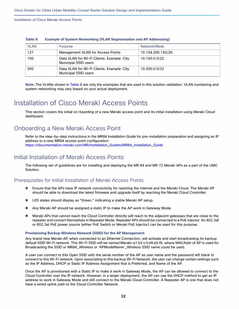
This section summarizes an example logical network (VLAN) configuration for the CKC UMC Solution network. Table 8 is an example list of VLANs implemented for this system validation.
31
Cisco Kinetic for Cities Urban Mobility—Crowd Starter Solution Design and Implementation Guide
Installation of Cisco Meraki Access Points
Note: The VLANs shown in Table 8 are only the examples that are used in this solution validation. VLAN numbering and system networking may vary based on your actual deployment.
Installation of Cisco Meraki Access PointsThis section covers the initial on-boarding of a new Meraki access point and its initial installation using Meraki Cloud dashboard.
Onboarding a New Meraki Access PointRefer to the step-by-step instructions in the MR84 Installation Guide for pre-installation preparation and assigning an IP address to a new MR84 access point configuration:https://documentation.meraki.com/MR/Installation_Guides/MR84_Installation_Guide
Initial Installation of Meraki Access PointsThe following set of guidelines are for installing and deploying the MR 84 and MR 72 Meraki APs as a part of the UMC Solution.
Prerequisites for Initial Installation of Meraki Access Points Ensure that the APs have IP network connectivity for reaching the internet and the Meraki Cloud. The Meraki AP
should be able to download the latest firmware and upgrade itself by reaching the Meraki Cloud Controller.
LED states should display as “Green,” indicating a stable Meraki AP setup.
Any Meraki AP should be assigned a static IP to make the AP work in Gateway Mode.
Meraki APs that cannot reach the Cloud Controller directly will reach to the adjacent gateways that are close to the repeater and convert themselves in Repeater Mode. Repeater APs should be connected to a PoE Injector. An 802.3af or 802.3at PoE power source (either PoE Switch or Meraki PoE Injector) can be used for this purpose.
Provisioning Backup Wireless Network (SSID) for the AP ManagementAny brand new Meraki AP, when connected to an Ethernet Connection, will activate and start broadcasting its backup default SSID Wi-Fi network. This Wi-Fi SSID will be named Meraki-a1:b2:c3:d4:e5:f6, where MACAddr of AP is used for Broadcasting the SSID or MR84_Wireless or ‘APModelName’_Wireless SSID name could be used.
A user can connect to this Open SSID with the serial number of the AP as user name and the password left blank to connect to this Wi-Fi network. Upon associating to this backup Wi-Fi Network, the user can change certain settings such as the IP Address, DHCP or Static IP Address Assignment that is Preferred, and Name of the AP.
Once the AP is provisioned with a Static IP to make it work in Gateway Mode, the AP can be allowed to connect to the Cloud Controller over the IP network. However, in a larger deployment, the AP can use the DHCP method to get an IP address to work in Gateway Mode and still connect to the Meraki Cloud Controller. A Repeater AP is one that does not have a wired uplink path to the Cloud Controller Network.
Table 8 Example of System Networking (VLAN Segmentation and AP Addressing)
VLAN Purpose Network/Mask
121 Management VLAN for Access Points 10.104.206.192/26
100 Data VLAN for Wi-Fi Clients. Example: City Municipal SSID users
10.100.0.0/22
200 Data VLAN for Wi-Fi Clients. Example: City Municipal SSID users
10.200.0.0/22
32
Cisco Kinetic for Cities Urban Mobility—Crowd Starter Solution Design and Implementation Guide
Configure System Networking
Refer to the Meraki document at the following URL for more details on the Meraki Gateway and Repeater Access Points:
https://documentation.meraki.com/MR/Other_Topics/Cisco_Meraki_Gateway_AP_vs._Repeater_AP
Meraki Dashboard SubscriptionAll Meraki Wireless APs have the same license regardless of the AP model number. Once the ENT subscription-based system manager agent license and wireless AP license are hosted on the Meraki Cloud Controller, the Cloud setup is ready to start the initial installation of Meraki APs to the Cloud Controller.
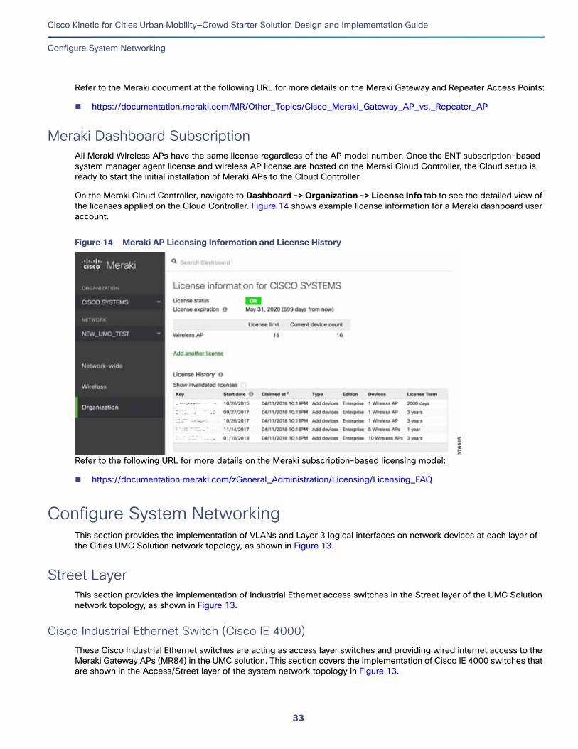
On the Meraki Cloud Controller, navigate to Dashboard -> Organization -> License Info tab to see the detailed view of the licenses applied on the Cloud Controller. Figure 14 shows example license information for a Meraki dashboard user account.
Figure 14 Meraki AP Licensing Information and License History
Refer to the following URL for more details on the Meraki subscription-based licensing model:
https://documentation.meraki.com/zGeneral_Administration/Licensing/Licensing_FAQ
Configure System NetworkingThis section provides the implementation of VLANs and Layer 3 logical interfaces on network devices at each layer of the Cities UMC Solution network topology, as shown in Figure 13.
Street LayerThis section provides the implementation of Industrial Ethernet access switches in the Street layer of the UMC Solution network topology, as shown in Figure 13.
Cisco Industrial Ethernet Switch (Cisco IE 4000)These Cisco Industrial Ethernet switches are acting as access layer switches and providing wired internet access to the Meraki Gateway APs (MR84) in the UMC solution. This section covers the implementation of Cisco IE 4000 switches that are shown in the Access/Street layer of the system network topology in Figure 13.
33

Cisco Kinetic for Cities Urban Mobility—Crowd Starter Solution Design and Implementation Guide
Configure System Networking
Configuring Network Layer 2 and Layer 3This section defines the implementation of VLANs on the Cisco IE 4000 switch.
1. Configure VLANs, which must be created along with port assignments on the Cisco IE 4000 switches:
IE4k-1(config)#vlan 100,121,200 end
IE4k-2(config)#vlan 100,121,200 end
Note: Repeat the step on all Cisco IE 4000 switches in the deployment based on the system networking configuration for your deployment. The above example configuration shows the Cisco IE 4000 switches configuration for the network topology in Figure 13.
2. Create port channel interfaces on the Cisco IE 4000 switches to the City layer Cisco Catalyst 4500-X switches in the network, as shown below. For example:
interface Port-channel1 description Connected to C4500X Switch Etherchannel switchport switchport mode trunkswitchport trunk allowed vlan 100,121,200
!
Repeat this step for each Cisco IE switch in the Street layer.
3. Enable EtherChannel on the appropriate physical switch ports connected to the Cisco Catalyst 4500-X switches. The following configuration shows the port channel assignment to switch physical port physical links to the Cisco Catalyst 4500-X switches. For example:
interface GigabitEthernet1/1description ##TO 4500X##
switchport mode trunkswitchport trunk allowed vlan 100,121,200
channel-group 1 mode active!interface GigabitEthernet1/2 description ##TO 4500X## switchport mode trunkswitchport trunk allowed vlan 100,121,200
channel-group 1 mode active!
Repeat this step for each Cisco IE switch in the Street layer on the appropriate ports.
4. Configure the Cisco IE 4000 switch ports where Meraki Gateway APs are connected. Internet/Meraki Cloud access for the APs must be available for the configured switchport. For example:
interface GigabitEthernet1/13 description Connected to MR84 Gateway Node in Meraki Mesh network switchport mode trunk switchport trunk allowed vlan 100,121,200
Repeat this step for each Meraki Gateway AP connecting to Cisco IE switches in the Street layer.
34

Cisco Kinetic for Cities Urban Mobility—Crowd Starter Solution Design and Implementation Guide
Configure System Networking
City LayerThis section provides the implementation of the core/backbone network switches in the City layer of the UMC solution network topology shown in Figure 13.
Core/Aggregation Cisco Catalyst 4500-X SwitchThe Figure 13 deployment model shows that the Cisco IE 4000 access switches are connected to the core/aggregation network switches.
Cisco Catalyst 4500-X switches are deployed in a pair, which provides network core, aggregation services, and Layer 3 routing functionalities for the Wi-Fi endpoints in the access layer. This section covers the implementation of the Cisco Catalyst 4500-X switch in the CKC UMC Solution City layer.
Configuring Virtual Switching SystemThe system topology in Figure 13 shows one of the implementations of the core network aggregation as a collapsed core/distribution model for this CKC UMC solution. The aggregation Cisco Catalyst 4500-X switches implement Virtual Switching System (VSS) to provide network redundancy at the City layer.
A VSS combines a pair of Cisco Catalyst 4500-X series switches into a single network element. The VSS manages the redundant links, which externally act as a single port channel. The VSS also simplifies network configuration and operation by reducing the number of Layer 3 routing neighbors and by providing a loop-free Layer 2 topology.
Note: The City network converges to a production network backbone where VSS may not be required to be implemented at the network aggregation level. In this case, VSS configuration steps do not need to be performed.
For the detailed implementation of VSS on the Cisco Catalyst 4500-X switch, refer to the Catalyst 4500 Series Switch Software Configuration Guide, IOS XE 3.9.xE and IOS 15.2(5)Ex at the following URL:
https://www.cisco.com/c/en/us/td/docs/switches/lan/catalyst4500/XE3-9-0E/15-25E/configuration/guide/xe-390-configuration/vss.html
Configuring Network Layer 2 and Layer 3This section defines the implementation of VLANs and Layer 3 logical interfaces on the Cisco Catalyst 4500-X switch.
1. Configure VLANs, which must be created along with port assignments on the Cisco Catalyst 4500-X switch:
CL-DS4500X-VSS(config)#vlan 100,121,200
2. Create the Layer 3 SVI for data VLANs. The example configuration below shows SVIs for the data VLANs and network management VLAN on the Cisco Catalyst 4500-X switch:
interface Vlan100 ip address 10.100.0.1 255.255.252.0
!interface Vlan121 ip address 10.104.206.216 255.255.255.192!interface Vlan200 ip address 10.200.0.1 255.255.252.0!
3. Create port channel interfaces on the Cisco Catalyst 4500-X to the Access layer Cisco IE 4000 switches in the network as shown below:
interface Port-channel201description Connected to IE4K-1 Switch Etherchannelswitchportswitchport mode trunk
35
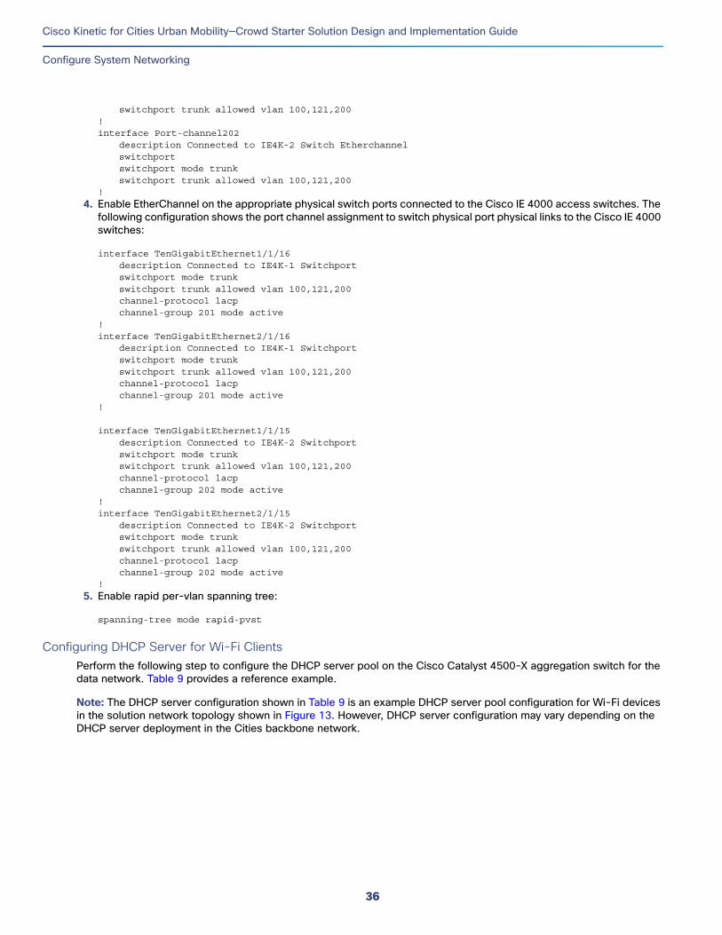
Cisco Kinetic for Cities Urban Mobility—Crowd Starter Solution Design and Implementation Guide
Configure System Networking
switchport trunk allowed vlan 100,121,200!interface Port-channel202
description Connected to IE4K-2 Switch Etherchannelswitchportswitchport mode trunkswitchport trunk allowed vlan 100,121,200
!
4. Enable EtherChannel on the appropriate physical switch ports connected to the Cisco IE 4000 access switches. The following configuration shows the port channel assignment to switch physical port physical links to the Cisco IE 4000 switches:
interface TenGigabitEthernet1/1/16description Connected to IE4K-1 Switchport
switchport mode trunkswitchport trunk allowed vlan 100,121,200channel-protocol lacp
channel-group 201 mode active!interface TenGigabitEthernet2/1/16 description Connected to IE4K-1 Switchport
switchport mode trunkswitchport trunk allowed vlan 100,121,200channel-protocol lacp
channel-group 201 mode active!
interface TenGigabitEthernet1/1/15description Connected to IE4K-2 Switchportswitchport mode trunkswitchport trunk allowed vlan 100,121,200channel-protocol lacp
channel-group 202 mode active!interface TenGigabitEthernet2/1/15 description Connected to IE4K-2 Switchport
switchport mode trunkswitchport trunk allowed vlan 100,121,200channel-protocol lacp
channel-group 202 mode active!
5. Enable rapid per-vlan spanning tree:
spanning-tree mode rapid-pvst
Configuring DHCP Server for Wi-Fi ClientsPerform the following step to configure the DHCP server pool on the Cisco Catalyst 4500-X aggregation switch for the data network. Table 9 provides a reference example.
Note: The DHCP server configuration shown in Table 9 is an example DHCP server pool configuration for Wi-Fi devices in the solution network topology shown in Figure 13. However, DHCP server configuration may vary depending on the DHCP server deployment in the Cities backbone network.
36
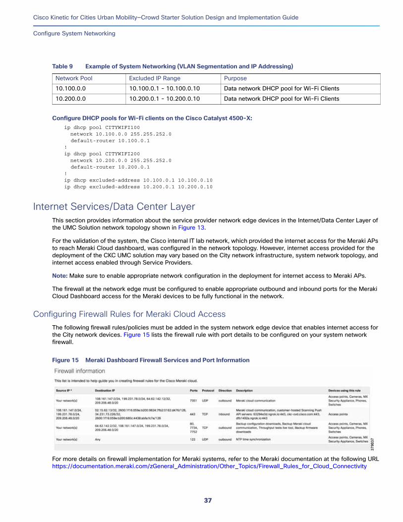
Cisco Kinetic for Cities Urban Mobility—Crowd Starter Solution Design and Implementation Guide
Configure System Networking
Configure DHCP pools for Wi-Fi clients on the Cisco Catalyst 4500-X: ip dhcp pool CITYWIFI100 network 10.100.0.0 255.255.252.0 default-router 10.100.0.1
!ip dhcp pool CITYWIFI200 network 10.200.0.0 255.255.252.0 default-router 10.200.0.1
!ip dhcp excluded-address 10.100.0.1 10.100.0.10ip dhcp excluded-address 10.200.0.1 10.200.0.10
Internet Services/Data Center LayerThis section provides information about the service provider network edge devices in the Internet/Data Center Layer of the UMC Solution network topology shown in Figure 13.
For the validation of the system, the Cisco internal IT lab network, which provided the internet access for the Meraki APs to reach Meraki Cloud dashboard, was configured in the network topology. However, internet access provided for the deployment of the CKC UMC solution may vary based on the City network infrastructure, system network topology, and internet access enabled through Service Providers.
Note: Make sure to enable appropriate network configuration in the deployment for internet access to Meraki APs.
The firewall at the network edge must be configured to enable appropriate outbound and inbound ports for the Meraki Cloud Dashboard access for the Meraki devices to be fully functional in the network.
Configuring Firewall Rules for Meraki Cloud AccessThe following firewall rules/policies must be added in the system network edge device that enables internet access for the City network devices. Figure 15 lists the firewall rule with port details to be configured on your system network firewall.
Figure 15 Meraki Dashboard Firewall Services and Port Information
For more details on firewall implementation for Meraki systems, refer to the Meraki documentation at the following URLhttps://documentation.meraki.com/zGeneral_Administration/Other_Topics/Firewall_Rules_for_Cloud_Connectivity
Table 9 Example of System Networking (VLAN Segmentation and IP Addressing)
Network Pool Excluded IP Range Purpose
10.100.0.0 10.100.0.1 - 10.100.0.10 Data network DHCP pool for Wi-Fi Clients
10.200.0.0 10.200.0.1 - 10.200.0.10 Data network DHCP pool for Wi-Fi Clients
37

Cisco Kinetic for Cities Urban Mobility—Crowd Starter Solution Design and Implementation Guide
Provisioning Cisco Meraki Wireless Network
Provisioning Cisco Meraki Wireless NetworkThis section covers the provisioning of Meraki Access Points in the Meraki dashboard, adding/removing APs to/from Meraki wireless networks, mesh and non-mesh wireless networks, and Meraki dashboard Layer 2/Layer 3 networking configuration for the network topology in Figure 13.
Adding Access Points to Meraki Dashboard and Wireless NetworksFollow these steps to add Meraki APs to the Meraki Dashboard:
1. In the Meraki Cloud Controller, navigate to Meraki Dashboard -> Organization -> Inventory Page.
2. Add the Serial Number details of the AP to be provisioned manually. Upon completion of this step, the APs will be visible to the Meraki Dashboard and you can move the APs to a different WLAN SSID Network.
Refer to the following URLs for more details:
https://meraki.cisco.com/blog/2014/05/from-unboxing-to-configuring-settings-all-under-one-roof/
https://documentation.meraki.com/zGeneral_Administration/Inventory_and_Devices/Adding_and_Removing_Devices_from_Dashboard_Networks
Optionally, you will also change (if needed) the management IP address configuration of the AP from Meraki dashboard. Refer to the following documentation for the step-by-step instructions:
https://documentation.meraki.com/MR/Monitoring_and_Reporting/Static_IP_Assignment_on_a_Cisco_Meraki_Access_Point
Meraki Mesh and Non-Mesh Wireless Networking
Mesh NetworkingMeraki's mesh networking functionality is different from the other Cisco AP functionality in terms of automatic, self-healing capability available on all APs. Meraki APs can work in either Gateway Mode or Repeater Mode.
Meraki determines whether a device should be in Repeater or Gateway Mode on boot up when the unit sends out a DHCP request. If it receives a DHCP reply from a device on the wired network, it assumes that it has a valid LAN connection and will become a Gateway AP.
If a Gateway AP is unable to reach the LAN gateway/upstream router, the AP will failover to Repeater Mode.
On the Meraki Dashboard, the Meraki Gateway AP and Repeater APs are differentiated with the AP symbol shown in Figure 16.
38

Cisco Kinetic for Cities Urban Mobility—Crowd Starter Solution Design and Implementation Guide
Provisioning Cisco Meraki Wireless Network
Figure 16 Meraki Gateway and Repeater AP Symbols
Repeater APs rely on wireless mesh links to reach the Meraki Cloud Controller or internet and are not directly connected to the wired network. As long as the Repeater AP has power and a strong wireless connection to another repeater or gateway, it will form a mesh link.
Note that is not feasible to configure a static IP address for a Repeater AP; doing so will automatically designate the Repeater device as a Gateway. Meraki APs that need to be configured in Repeater Mode should preferably be connected to a PoE Injector, which is 802.3af-capable or has an 802.3at PoE power source Ethernet Port (PoE switch or Meraki PoE Injector). If the PoE switch-based powering of repeaters is performed, then ensure that the switch port does not provide IP network connectivity and that the DHCP-based IP is not assigned to the Repeater AP; otherwise, it will fall back into Gateway Mode.
For more information on Meraki APs mesh networking, refer the following Meraki documentation:
https://documentation.meraki.com/MR/Deployment_Guides/Mesh_Deployment_Guide_(CVD)
https://documentation.meraki.com/MR/WiFi_Basics_and_Best_Practices/Mesh_Networking
Meraki Dashboard Networking ConfigurationThis section provides Cisco Meraki Cloud dashboard network-specific implementation details for Meraki APs in the system network, as shown in Figure 13.
Configuring Wireless Network SettingsThe Cisco Meraki Cloud dashboard is based on the backbone core and wireless network deployment for the CKC UMC solution. Wireless SSID settings need to be edited for IP addressing, traffic routing, and VLAN tagging of the Wi-Fi clients’ data traffic. The following sections describe wireless network settings at the Meraki Dashboard for the network and APs deployed in the Street layer of the system topology shown in Figure 13.
Wi-Fi Clients Addressing and Traffic FlowCisco Meraki wireless networks assign the IP addresses to Wi-Fi clients/end devices at the Street layer in the following three major modes:
39
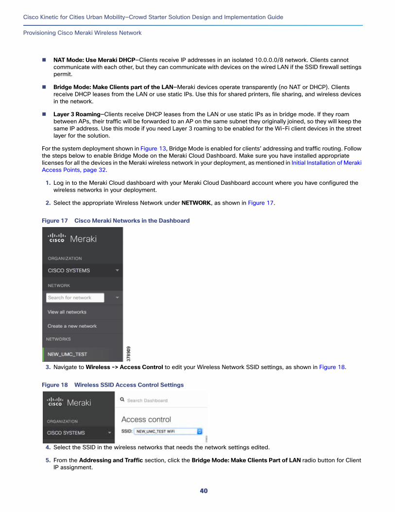
Cisco Kinetic for Cities Urban Mobility—Crowd Starter Solution Design and Implementation Guide
Provisioning Cisco Meraki Wireless Network
NAT Mode: Use Meraki DHCP—Clients receive IP addresses in an isolated 10.0.0.0/8 network. Clients cannot communicate with each other, but they can communicate with devices on the wired LAN if the SSID firewall settings permit.
Bridge Mode: Make Clients part of the LAN—Meraki devices operate transparently (no NAT or DHCP). Clients receive DHCP leases from the LAN or use static IPs. Use this for shared printers, file sharing, and wireless devices in the network.
Layer 3 Roaming—Clients receive DHCP leases from the LAN or use static IPs as in bridge mode. If they roam between APs, their traffic will be forwarded to an AP on the same subnet they originally joined, so they will keep the same IP address. Use this mode if you need Layer 3 roaming to be enabled for the Wi-Fi client devices in the street layer for the solution.
For the system deployment shown in Figure 13, Bridge Mode is enabled for clients’ addressing and traffic routing. Follow the steps below to enable Bridge Mode on the Meraki Cloud Dashboard. Make sure you have installed appropriate licenses for all the devices in the Meraki wireless network in your deployment, as mentioned in Initial Installation of Meraki Access Points, page 32.
1. Log in to the Meraki Cloud dashboard with your Meraki Cloud Dashboard account where you have configured the wireless networks in your deployment.
2. Select the appropriate Wireless Network under NETWORK, as shown in Figure 17.
Figure 17 Cisco Meraki Networks in the Dashboard
3. Navigate to Wireless -> Access Control to edit your Wireless Network SSID settings, as shown in Figure 18.
Figure 18 Wireless SSID Access Control Settings
4. Select the SSID in the wireless networks that needs the network settings edited.
5. From the Addressing and Traffic section, click the Bridge Mode: Make Clients Part of LAN radio button for Client IP assignment.
40

Cisco Kinetic for Cities Urban Mobility—Crowd Starter Solution Design and Implementation Guide
Integration of CKC with Meraki Wireless Networks
6. From the VLAN Tagging drop-down menu, select Use VLAN tagging.
7. Add the VLAN IDs (for example, VLAN 100 and VLAN 200 in the network) for the client data traffic VLAN tagging for the appropriate APs publishing the selected SSID in Step 4 above.
8. Click Save Changes to save the SSID configurations.
For more details on SSID modes on Meraki Wireless networks, refer to the following Meraki documentation URL:
https://documentation.meraki.com/MR/Client_Addressing_and_Bridging/SSID_Modes_for_Client_IP_Assignment
Integration of CKC with Meraki Wireless NetworksCKC Urban Mobility Crowd solution use cases are implemented by integrating Cisco Meraki cloud dashboard with Cisco Kinetic for Cities on cloud. This is achieved by configuring,
1. CKC Crowd Meraki provider extension for a CKC tenant
2. CKC Callback URL registration on Meraki dashboard
CKC Configuration PrerequisitesThe Cisco CKC Cloud Operations team configures the CKC Extension for integrating the CKC tenant’s Meraki Wireless Network with CKC. Hence, the following details are provided from Meraki dashboard to CKC Operation team:
1. Meraki dashboard API Access Key
2. Validator and Secret to receive Scanning API POST from Meraki dashboard
Note: Optionally, the CKC Operation team may ask Meraki dashboard server host and account details to make sure the CKC callback URL configuration on Meraki dashboard is successful and CKC receives HTTP(S) POSTs from Meraki dashboard.
Getting Meraki Dashboard API Access KeyFollow the steps in the Meraki documentation below to enable and generate your Meraki dashboard account API access key:
https://documentation.meraki.com/zGeneral_Administration/Other_Topics/The_Cisco_Meraki_Dashboard_API
Getting Meraki Scanning API Validator and SecretFollow the steps in the “Enable Scanning API” section of the Meraki document below to get Validator and configure Secret value to be shared with CKC Operations team:
https://documentation.meraki.com/MR/Monitoring_and_Reporting/Scanning_API
Registering CKC POST URL on Meraki DashboardAn HTTP or HTTPS callback POST URL provided by the CKC Operation team is configured on Meraki dashboard to validate and register that CKC URL to receive location analytics Scanning API messages from Meraki dashboard.
Also, CKC periodically polls the Meraki Dashboard using Dashboard API and pulls the data for the AP’s physical map location data attributes in order to update the corresponding AP's data on the CKC UI Dashboard and Map View. Once this is done, the CKC will now receive the Wi-Fi Scanning API data (every 90-120 Seconds) from the Meraki dashboard using the HTTP GET and POST methods to the CKC.
41

Cisco Kinetic for Cities Urban Mobility—Crowd Starter Solution Design and Implementation Guide
Integration of CKC with Meraki Wireless Networks
CKC Mobility Crowd use cases rely on the data coming in from the Meraki Scanning API using this method. Refer to the following URL for detailed information about Meraki Scanning API and attributes coming in JSON format:
https://documentation.meraki.com/MR/Monitoring_and_Reporting/Location_Analytics
Follow these steps to register CKC POST URL on Merkai dashboard:
1. Navigate to Network-wide -> General from the left pane after logging in to your Meraki dashboard account for the selected wireless network.
2. Add a Post URL by clicking the Add a Post URL hyperlink and copy and paste the CKC Post URL for the secret shared with the CKC operation team, as shown in Figure 19.
Figure 19 POST URL-based Meraki Dashboard and Cisco Kinetic for Cities Integration
The organization (CISCO SYSTEMS) and the APs that are mapped to the Wi-Fi Network ESSID (NEW_UMC_TEST) associated to this organization would be considered for publishing the Wi-Fi Scanning API messages from Meraki MSP to the CKC.
3. Click the Validate button next to the URL. Once the CKC extension URL validates the HTTPS GET message as shown in Figure 20 (highlighted in red rectangle), the Validator Token is returned to the Meraki dashboard to initiate Scanning API POST messages to CKC.
Figure 20 POST URL-Validation on Meraki Dashboard for CKC Integration
A sample JSON Output from the Scanning API is shown below for the Wi-Fi Clients Record Last Seen details.
</Location><seenTime>2018-01-19T05:29:43Z</seenTime><clientMac>c8:fd:19:43:6d:53</clientMac><seenEpoch>1516339783</seenEpoch><rssi>-69</rssi>
For more information on the Meraki Scanning API, refer to the following URL on Meraki documentation:
https://documentation.meraki.com/MR/Monitoring_and_Reporting/Scanning_API
42

Cisco Kinetic for Cities Urban Mobility—Crowd Starter Solution Design and Implementation Guide
Configuring End-to-End-Security
Configuring End-to-End-SecurityThis section covers the security best practice configuration for the CKC Urban Mobility Crowd solution. End-to-end security best practices configuration to be enabled from Street Layer Meraki APs to the CKC Cloud are discussed with a configuration example for the solution topology in Figure 13.
Configuring Cisco Meraki Wireless Network Security
Configuring Network SegmentationOnce the AP is on boarded to the Meraki Dashboard, it is often a good implementation practice to ensure that the data and management traffic from Meraki APs to the Meraki dashboard and vice versa are separated using different VLAN as discussed in System Networking, page 31.
Make sure to configure the VLAN ID of the management traffic to VLAN tag the management traffic to uplink switch trunk port.
Refer to the “Tagging a Management VLAN on a Cisco Meraki Device” section on the following URL for configuration steps:
https://documentation.meraki.com/MR/Monitoring_and_Reporting/Understanding_and_Configuring_Management_VLANs_on_Cisco_Meraki_Devices
It is recommended to configure VLANs on your network to limit broadcast traffic, segment traffic, or restrict traffic for security reasons. If you already have VLANs implemented on your wired network, you can extend this to your wireless network as well with MR Access Points which support IEEE 802.1Q VLAN tagging in Bridge mode. These VLAN tags can be applied per-SSID, per-user, per-device or per-AP.
Refer to the following documentation on “VLAN Tagging on MR Access Points” for configuring per SSID VLAN tagging in Meraki dashboard for Wireless SSID networks in the street layer:
https://documentation.meraki.com/MR/Client_Addressing_and_Bridging/VLAN_Tagging_on_MR_Access_Points
Configuring Encryption and AuthenticationIt is often recommended to configure wireless network security for client devices authentication and encrypting the data traffic. The Cisco Meraki Access Points supports a wide variety of encryption and authentication methods, from simple, open access to WPA2-Enterprise with 802.1x authentication.
Configure the appropriate authentication and encryption method as needed for your wireless network infrastructure security. Refer to the following URLs for more details on Meraki Access points Encryption and Authentication:
https://documentation.meraki.com/MR/Encryption_and_Authentication/Wireless_Encryption_and_Authentication_Overview
https://documentation.meraki.com/MR/Encryption_and_Authentication/Configuring_RADIUS_Authentication_with_WPA2-Enterprise
Note: For the Cities Urban Mobility Crowd solution validation for the network topology in Figure 13, the WPA2-PSK (Pre-shared Key) with user password was used as a Wi-Fi device authentication mechanism. However, it is recommended to use WPA2-Enterprise or any other authentication and encryption method which you prefer as per your network deployment.
43

Cisco Kinetic for Cities Urban Mobility—Crowd Starter Solution Design and Implementation Guide
Cisco Kinetic for Cities Provisioning
Meraki Dashboard and CKC Cloud Security ConsiderationsA secure communication using HTTPS protocol is established between Meraki dashboard and CKC platform. To enable HTTPS-secured connection, a certificate has to be generated for CKC, as per the Certificate Signing Request (CSR) process and installed on CKC since Meraki dashboard recommends using a Certificate Authority (CA)-signed certificate. It is important to remember that self-signed certificates are not recommended for production environments. Because it is not tamper proof, CA-signed certificates are more secure and are considered best practice. CKC supports the TLS 1.2 Secured tunnel with Meraki dashboard.
Refer to the following documentation on “Certificate Requirements for TLS” to generate CKC certificate for establishing a secure connection with Meraki dashboard:
https://documentation.meraki.com/zGeneral_Administration/Other_Topics/Certificate_Requirements_for_TLS
The CKC Operations (DevOps) team generates the certificate as per the Meraki certificate requirements and installs it on the CKC cloud instance which integrates with Meraki dashboard. Once the certificate is installed on CKC, it provides a secured URL to register with Meraki as described in Registering CKC POST URL on Meraki Dashboard, page 41.
When using HTTPS, the endpoint must have a valid certificate signed by a valid public Certificate Authority. If it is not or it is expired, revoked, or otherwise invalid, a session cannot be established to allow the incoming POST.
In some circumstances, a signed certificate can be valid, but still unrecognized, if signed by an intermediary CA unknown to the Meraki Dashboard. For this reason, we recommend including the full CA chain when using HTTPS.
Registering a secure CKC Post URL on Meraki dashboard requires CKC Cloud and Meraki dashboard be hosted on the same geo-region (Round Trip Time must be less than 500ms). If this the round-trip latency between these hosts on the cloud is higher than 500ms, the CKC HTTPS URL validation will fail. Hence, it is recommended to host CKC and your Meraki wireless networks dashboard on the same or very near geo location.
Note: Make sure to check with the CKC Operations team and Meraki technical support team to understand on which geo-regions your CKC instance/tenant and Meraki wireless network organization are hosted. If they are geographically hosted on different locations which could result in higher RTT or latency, you need to work with CKC Operations or Cisco Meraki support team to change the hosted server as recommended.
Cisco Kinetic for Cities ProvisioningUrban Mobility Crowd solution use cases are enabled on CKC by provisioning CKC with specific functionality for Tenants, Domains, Policy, Reporting, and Device Engines. The CKC software platform has Create, Remove, Update, Delete (CRUD)-based functionality that relate to a standard software platform.
The configuration of tenants, domains per tenant, and CKC tenant operator user are done by the CKC operations team on cloud CKC instance using administrator/super user rights.
Note: Urban Mobility Crowd use cases navigation on CKC dashboard is generally done using CKC Operator user role. If you need to configure additional users, you would need CKC administrator user credentials for your tenant provided by the CKC operations team.
Configuring CKC Users and RolesBy default, CKC operations team create a user with operator rights for you to log on to CKC dashboard to see domain specific features/use cases enabled for that tenant. If additional users are required to be created, you must log in as CKC administrator user with privileges to create/modify/delete users for a tenant. For step-by-step instructions on creating/modifying/deleting users, refer to the “Creating Users” section on “CKC Dashboard Administrator Guide” provided by the CKC Operations team.
44

Cisco Kinetic for Cities Urban Mobility—Crowd Starter Solution Design and Implementation Guide
Cisco Kinetic for Cities Provisioning
Figure 21 shows an example list of users created for a region in CKC tenant.
Figure 21 Adding and Updating New Users with CKC Dashboard Administrator Login
Configuring CKC User Roles and RegionsUser roles determine tabs and domains access permissions for the user logging on to CKC Dashboard. Creation of new roles and access permission configuration is done by the CKC Operations team as per your requirements. For more details on roles, refer to the “Role Assignment” section on “CKC Dashboard Administrator Guide” provided by the CKC Operations team.
Figure 22 shows an example role assignment for “blroperator” user.
Figure 22 Example User Role Assignment
Once the administrator has created the User and mapped them to a User Role, they can then provide the hierarchical access for different Locations present in the CKC for the same Tenant. Depending on the position or location, the user profile can be assigned a specific location so that only the assigned location is accessible when the user is logging in with those credentials. Location in this Context refers to the position of a tenant, as shown in Figure 23. Assign Location to a tenant is used in CKC dashboard to position a location (Region defined) within a Tenant.
For more details on region mapping to the users of a tenant, refer to the “Location Assignment” section in the CKC Dashboard Administrator Guide provided by the CKC Operations team. Figure 23 shows an example region mapping or location assignment for a tenant user.
45

Cisco Kinetic for Cities Urban Mobility—Crowd Starter Solution Design and Implementation Guide
Cisco Kinetic for Cities Provisioning
Figure 23 Mapping Location to Tenants and Regions for Administrator User Profile Management
Urban Mobility Crowd Use CasesThis section covers the steps to navigate the CKC dashboard to get the details of the following Urban Mobility Crowd (Meraki provider) use cases implemented on CKC4.0 release.
1. Total devices Count (including Connected devices) per Access Point (ROI) for Wi-Fi devices
2. Dwell Time per Access Point (ROI) for Wi-Fi devices
Getting Total Devices CountUrban Mobility Crowd solution use cases depend on the Wi-Fi devices for calculating the total devices count. CKC depends on the data that the Meraki Scanning API exposes to the CKC Dashboard.
CKC dashboard provides the total devices count and connected devices count per AP or for a geo-region in which multiple APs are mapped to the region.
Note: BLE-based Total devices count and BLE-based dwell time for the UMC Solution are applicable only for future releases and are not supported in the CKC 4.0 Release.
After integrating the CKC with the Meraki Dashboard, the APs are available in the CKC dashboard. Follow the steps below to navigate to total devices Map View of Crowd domain:
1. Login to CKC dashboard as Operator user (e.g., blroperator).
2. Navigate to Map View -> click Module Layers -> select Urban Mobility -> select Crowd -> select Wifi. You see a Map View with the details of all available APs in the configured region, as shown in Figure 24.
46
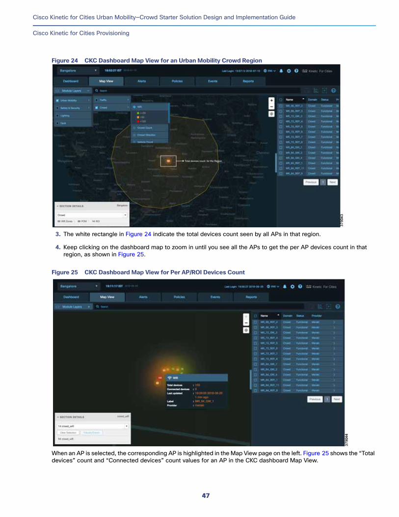
Cisco Kinetic for Cities Urban Mobility—Crowd Starter Solution Design and Implementation Guide
Cisco Kinetic for Cities Provisioning
Figure 24 CKC Dashboard Map View for an Urban Mobility Crowd Region
3. The white rectangle in Figure 24 indicate the total devices count seen by all APs in that region.
4. Keep clicking on the dashboard map to zoom in until you see all the APs to get the per AP devices count in that region, as shown in Figure 25.
Figure 25 CKC Dashboard Map View for Per AP/ROI Devices Count
When an AP is selected, the corresponding AP is highlighted in the Map View page on the left. Figure 25 shows the “Total devices” count and “Connected devices” count values for an AP in the CKC dashboard Map View.
47

Cisco Kinetic for Cities Urban Mobility—Crowd Starter Solution Design and Implementation Guide
Cisco Kinetic for Cities Provisioning
Getting Devices Dwell Time for an AP (ROI)The average dwell time of devices per AP is calculated as per the logic described in Crowd Use Case Computation Logic at CKC, page 13. Follow these steps to get the average dwell time of detected and connected devices per AP:
1. Login to CKC dashboard as Operator user (e.g., blroperator).
2. Navigate to Map View -> click Module Layers -> select Urban Mobility -> select Crowd -> select Dwell Time. The CKC dashboard displays a map view of the Crowd Dwell Time use case, as shown in Figure 26.
Figure 26 CKC Dashboard Map View for Dwell Time
3. Keep clicking on the dashboard map to zoom in until you see all the APs to get the per AP average dwell time on the map view, as shown in Figure 27.
48

Cisco Kinetic for Cities Urban Mobility—Crowd Starter Solution Design and Implementation Guide
Cisco Kinetic for Cities Provisioning
Figure 27 CKC Dashboard Map View for Average Dwell Time per AP/ROI
By selecting the individual AP from the right pane that displays a list of all available APs in the configured geo region, the dwell time value of that AP gets highlighted in the map view.
4. Move the cursor on the highlighted AP to see the individual AP’s dwell time value, as shown in Figure 27.
Configuring Crowd Events and ReportsThis section covers the implementation of Urban Mobility Crowd events and reports which are supported in CKC dashboard release 4.0.
Configuring Overcrowding EventsAn Event is a set of a trigger and an action. A congestion or overcrowding event is created when the count of specified personal devices in a region reaches the threshold value. Follow these steps to configure overcrowding event notification threshold on the CKC dashboard:
1. Login to CKC dashboard as Operator user (e.g., blroperator).
2. Navigate to Events tab -> click Create to create an event.
3. Select Region -> ROI Over Crowding Trigger with Location -> PersonalDevice Overall from the drop-down menu to enter overcrowding threshold value for which notification should be triggered on the CKC dashboard, as shown in Figure 28.
49

Cisco Kinetic for Cities Urban Mobility—Crowd Starter Solution Design and Implementation Guide
Cisco Kinetic for Cities Provisioning
Figure 28 CKC Dashboard Mobility Over Crowding Event Parameters
4. Click Next -> select Create Event for Mobility ROI -> Overcrowding -> event severity (as needed) from the drop-down menus. Figure 29 shows an example Action configuration for Overcrowding event.
Figure 29 CKC Dashboard Mobility Over Crowding Event Action Parameters
5. Click Next and check the Action rule. Click Next and name the Event to be created and click Save. This completes the Event configuration of Over Crowding notification.
6. Apply the configured event to a Mobility region for which dashboard notifications are required. Click the Map View tab -> click Select Region (highlighted in white rectangle in Figure 30) -> click Policies/Events (highlighted in red rectangle), as shown in Figure 30).
50

Cisco Kinetic for Cities Urban Mobility—Crowd Starter Solution Design and Implementation Guide
Cisco Kinetic for Cities Provisioning
Figure 30 CKC Dashboard Mobility Over Crowding Event Region Selection
7. Click the Apply Event tab and select the Event you created from the drop-down menu. Click Apply to save the event configuration for the selected region. Figure 31 shows an example Overcrowding event applied on a selected region per ROI or AP.
Figure 31 CKC Dashboard Mobility Over Crowding Event Application on a Region
8. Once Events are applied to a region, the notification gets triggered along with alerts on the CKC dashboard when the configured event threshold is reached per ROI. Figure 32 shows an example Overcrowding event notification on CKC dashboard (highlighted in red rectangle). Figure 33 shows an example list of “Alerts” generated for the overcrowding event triggers.
51

Cisco Kinetic for Cities Urban Mobility—Crowd Starter Solution Design and Implementation Guide
Cisco Kinetic for Cities Provisioning
Figure 32 CKC Dashboard Mobility Overcrowding Event Notification
Figure 33 CKC Dashboard Mobility Overcrowding Alerts
For more details on Events configuration, refer to the Cisco Kinetic for Cities Dashboard User Guide.
Note: Overcrowding Events created are applied at a tenant region level in CKC dashboard, however Events are applied for each Mobility ROI or Access Point in that region. See Caveats, page 53 for more details.
Getting Average Dwell Time Trend ReportCKC enables customers to discover, compare, and correlate data across various domains to discover the patterns that were previously hidden. You can generate a Mobility Average Dwell Time Trend report that shows the average people (personal devices) dwell time for a region sampled every minute for the day, week, month, or year.
Refer to the “Reports” and “Mobility Reports” sections in Cisco Kinetic for Cities Dashboard User Guide for the step-by-step instructions on generating reports for Mobility Average Dwell Time Trend in the Urban Mobility Crowd solution.
52
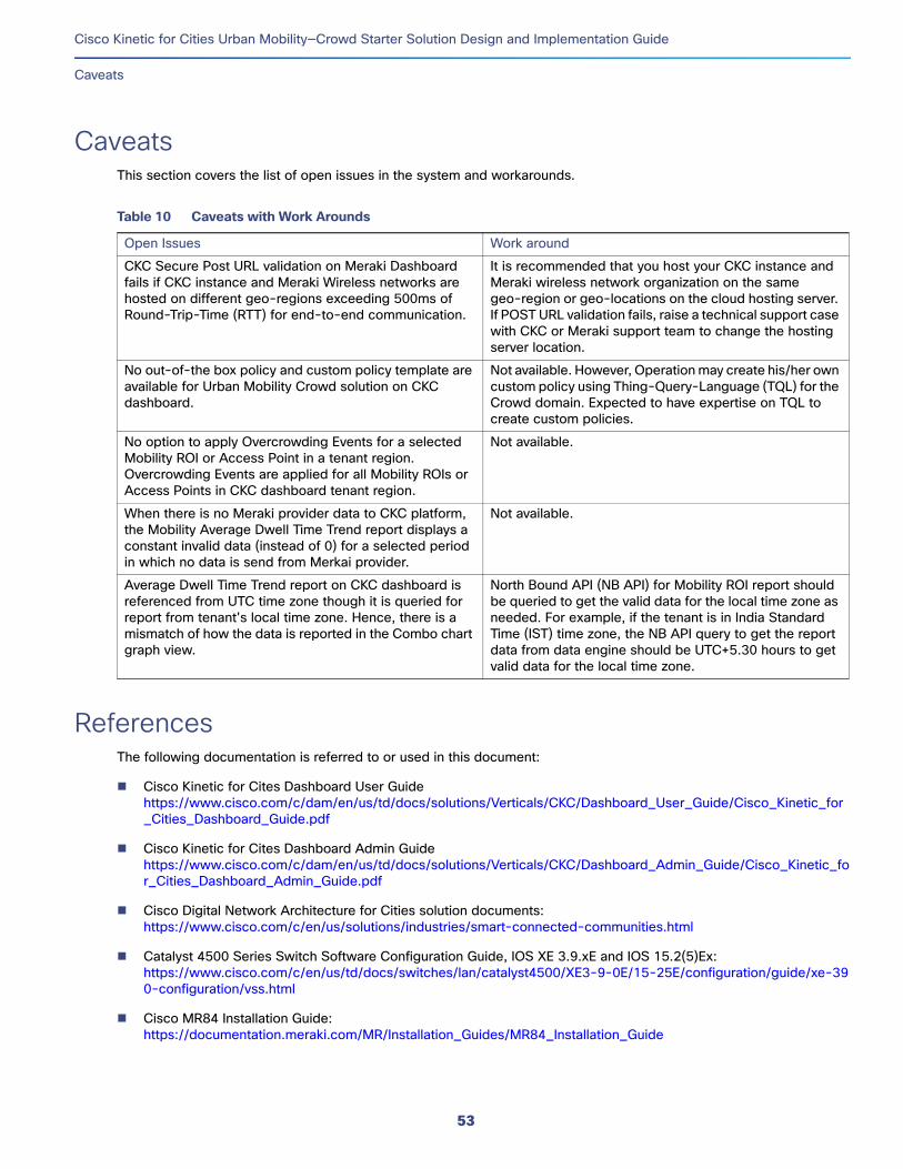
Cisco Kinetic for Cities Urban Mobility—Crowd Starter Solution Design and Implementation Guide
Caveats
CaveatsThis section covers the list of open issues in the system and workarounds.
ReferencesThe following documentation is referred to or used in this document:
Cisco Kinetic for Cites Dashboard User Guidehttps://www.cisco.com/c/dam/en/us/td/docs/solutions/Verticals/CKC/Dashboard_User_Guide/Cisco_Kinetic_for_Cities_Dashboard_Guide.pdf
Cisco Kinetic for Cites Dashboard Admin Guidehttps://www.cisco.com/c/dam/en/us/td/docs/solutions/Verticals/CKC/Dashboard_Admin_Guide/Cisco_Kinetic_for_Cities_Dashboard_Admin_Guide.pdf
Cisco Digital Network Architecture for Cities solution documents:https://www.cisco.com/c/en/us/solutions/industries/smart-connected-communities.html
Catalyst 4500 Series Switch Software Configuration Guide, IOS XE 3.9.xE and IOS 15.2(5)Ex:https://www.cisco.com/c/en/us/td/docs/switches/lan/catalyst4500/XE3-9-0E/15-25E/configuration/guide/xe-390-configuration/vss.html
Cisco MR84 Installation Guide:https://documentation.meraki.com/MR/Installation_Guides/MR84_Installation_Guide
Table 10 Caveats with Work Arounds
Open Issues Work around
CKC Secure Post URL validation on Meraki Dashboard fails if CKC instance and Meraki Wireless networks are hosted on different geo-regions exceeding 500ms of Round-Trip-Time (RTT) for end-to-end communication.
It is recommended that you host your CKC instance and Meraki wireless network organization on the same geo-region or geo-locations on the cloud hosting server. If POST URL validation fails, raise a technical support case with CKC or Meraki support team to change the hosting server location.
No out-of-the box policy and custom policy template are available for Urban Mobility Crowd solution on CKC dashboard.
Not available. However, Operation may create his/her own custom policy using Thing-Query-Language (TQL) for the Crowd domain. Expected to have expertise on TQL to create custom policies.
No option to apply Overcrowding Events for a selected Mobility ROI or Access Point in a tenant region. Overcrowding Events are applied for all Mobility ROIs or Access Points in CKC dashboard tenant region.
Not available.
When there is no Meraki provider data to CKC platform, the Mobility Average Dwell Time Trend report displays a constant invalid data (instead of 0) for a selected period in which no data is send from Merkai provider.
Not available.
Average Dwell Time Trend report on CKC dashboard is referenced from UTC time zone though it is queried for report from tenant's local time zone. Hence, there is a mismatch of how the data is reported in the Combo chart graph view.
North Bound API (NB API) for Mobility ROI report should be queried to get the valid data for the local time zone as needed. For example, if the tenant is in India Standard Time (IST) time zone, the NB API query to get the report data from data engine should be UTC+5.30 hours to get valid data for the local time zone.
53
Cisco Kinetic for Cities Urban Mobility—Crowd Starter Solution Design and Implementation Guide
References
Cisco Meraki VLAN Tagging:https://documentation.meraki.com/MR/Client_Addressing_and_Bridging/VLAN_Tagging
Cisco Meraki Firewall Rules for Cloud Connectivity:https://documentation.meraki.com/zGeneral_Administration/Other_Topics/Firewall_Rules_for_Cloud_Connectivity
Cisco Meraki Wireless Networks Clients SSID modes for IP addressing:https://documentation.meraki.com/MR/Client_Addressing_and_Bridging/SSID_Modes_for_Client_IP_Assignment
Cisco Meraki Dashboard API:https://documentation.meraki.com/zGeneral_Administration/Other_Topics/The_Cisco_Meraki_Dashboard_API
Cisco Meraki Licensing FAQ:https://documentation.meraki.com/zGeneral_Administration/Licensing/Licensing_FAQ
Cisco Meraki TLS Support Details:https://documentation.meraki.com/zGeneral_Administration/Other_Topics/Certificate_Requirements_for_TLS
Cisco Meraki Security Tools and Best Practices for Administrators:https://meraki.cisco.com/trust#tools
Cisco Meraki Location Analytics Scanning API:https://documentation.meraki.com/MR/Monitoring_and_Reporting/Scanning_API
Tagging a Management VLAN on a Cisco Meraki Device:https://documentation.meraki.com/MR/Monitoring_and_Reporting/Understanding_and_Configuring_Management_VLANs_on_Cisco_Meraki_Devices
VLAN Tagging on MR Access Points:https://documentation.meraki.com/MR/Client_Addressing_and_Bridging/VLAN_Tagging_on_MR_Access_Points
Cisco Meraki Wireless Encryption and Authentication Overview:https://documentation.meraki.com/MR/Encryption_and_Authentication/Wireless_Encryption_and_Authentication_Overview
Configuring RADIUS Authentication with WPA2-Enterprise:https://documentation.meraki.com/MR/Encryption_and_Authentication/Configuring_RADIUS_Authentication_with_W PA2-Enterprise
Cisco Kinetic for Cities DevNet:https://developer.cisco.com/docs/scdp/#cisco-kinetic-for-cities/cisco-kinetic-for-cities-hr
Thing-Query-Language (TQL):https://developer.cisco.com/docs/scdp/#!thing-query-language/thing-query-language-hr
Note: Some of the information listed above is only available to Cisco Channel Partners and Cisco personnel with a valid CCO (Cisco Connection Online) login. Customers and other interested parties should contact their local Cisco distributor or Cisco Account Manager for additional details.
54
Cisco Kinetic for Cities Urban Mobility—Crowd Starter Solution Design and Implementation Guide
Glossary
Glossary
Term Definition
A
AAA Authentication, Authorization and Accounting
ACL Access Control List
ARP Address Resolution Protocol
ASA Adaptive Security Appliance
API Application Programming Interface
AP Access Point
B
BLE Bluetooth Low Energy
BoM Bill of Material
C
CVD Cisco Validated Design
CRD Cisco Recommended Design
CT Configuration Tool
CKC Cisco Kinetic for Cities
D
DHCP Dynamic Host Configuration Protocol
DNA Digital Network Architecture
DNS Domain Name Server
DevOps Development & Operations
F
FAQ Frequently Asked Questions
FW Firewall
H
HTTP Hypertext Transfer Protocol
HTTPS HTTP over SSL
I
IPv4 Internet Protocol Version 4
IE Industrial Ethernet
J
JSON JavaScript Object Notation
L
L2 Layer 2
L3 Layer 3
LACP Link Aggregation Control Protocol
LLDP Link Layer Discovery Protocol
LDAP Lightweight Directory Access Protocol
55

Cisco Kinetic for Cities Urban Mobility—Crowd Starter Solution Design and Implementation Guide
Glossary
LAN Local Area Network
N
NTP Network Time Protocol
O
OTT Over the Top
P
PoE Power over Ethernet
PSK Pre-Shared Key
R
RADIUS Remote Authentication Dial-In User Service
ROI Region of Interest
S
SSH Secure Shell
SNMP Simple Network Management Protocol
SSID Service Set Identifier
SVI Switched Virtual Interface
T
TACACS Terminal Access Controller Access Control System
TFTP Trivial File Transfer Protocol
TCP Transmission Control Protocol
TQL Thing Query Language
TLV Type Length Value
TLS Transport Layer Security
U
UCS Unified Computing System
UPoE Universal Power over Ethernet
UDP User Datagram Protocol
UMC Urban Mobility Crowd
URL Uniform Resource Location
V
VM Virtual Machine
VLAN Virtual Local Area Network
VSS Virtual Switching System
W
WLAN Wireless Local Area Network
Term Definition
56