Embed Size (px)
Citation preview

Cisco DOCSIS 3.0 Downstream Solution Design and Implementation Guide
September 2014
Cisco Systems, Inc.www.cisco.com
Cisco has more than 200 offices worldwide. Addresses, phone numbers, and fax numbers are listed on the Cisco website at www.cisco.com/go/offices.

THE SPECIFICATIONS AND INFORMATION REGARDING THE PRODUCTS IN THIS MANUAL ARE SUBJECT TO CHANGE WITHOUT NOTICE. ALL STATEMENTS, INFORMATION, AND RECOMMENDATIONS IN THIS MANUAL ARE BELIEVED TO BE ACCURATE BUT ARE PRESENTED WITHOUT WARRANTY OF ANY KIND, EXPRESS OR IMPLIED. USERS MUST TAKE FULL RESPONSIBILITY FOR THEIR APPLICATION OF ANY PRODUCTS.
THE SOFTWARE LICENSE AND LIMITED WARRANTY FOR THE ACCOMPANYING PRODUCT ARE SET FORTH IN THE INFORMATION PACKET THAT SHIPPED WITH THE PRODUCT AND ARE INCORPORATED HEREIN BY THIS REFERENCE. IF YOU ARE UNABLE TO LOCATE THE SOFTWARE LICENSE OR LIMITED WARRANTY, CONTACT YOUR CISCO REPRESENTATIVE FOR A COPY.
The Cisco implementation of TCP header compression is an adaptation of a program developed by the University of California, Berkeley (UCB) as part of UCB’s public domain version of the UNIX operating system. All rights reserved. Copyright © 1981, Regents of the University of California.
NOTWITHSTANDING ANY OTHER WARRANTY HEREIN, ALL DOCUMENT FILES AND SOFTWARE OF THESE SUPPLIERS ARE PROVIDED “AS IS” WITH ALL FAULTS. CISCO AND THE ABOVE-NAMED SUPPLIERS DISCLAIM ALL WARRANTIES, EXPRESSED OR IMPLIED, INCLUDING, WITHOUT LIMITATION, THOSE OF MERCHANTABILITY, FITNESS FOR A PARTICULAR PURPOSE AND NONINFRINGEMENT OR ARISING FROM A COURSE OF DEALING, USAGE, OR TRADE PRACTICE.
IN NO EVENT SHALL CISCO OR ITS SUPPLIERS BE LIABLE FOR ANY INDIRECT, SPECIAL, CONSEQUENTIAL, OR INCIDENTAL DAMAGES, INCLUDING, WITHOUT LIMITATION, LOST PROFITS OR LOSS OR DAMAGE TO DATA ARISING OUT OF THE USE OR INABILITY TO USE THIS MANUAL, EVEN IF CISCO OR ITS SUPPLIERS HAVE BEEN ADVISED OF THE POSSIBILITY OF SUCH DAMAGES.
Cisco and the Cisco logo are trademarks or registered trademarks of Cisco and/or its affiliates in the U.S. and other countries. To view a list of Cisco trademarks, go to this URL: www.cisco.com/go/trademarks. Third-party trademarks mentioned are the property of their respective owners. The use of the word partner does not imply a partnership relationship between Cisco and any other company. (1110R)
Any Internet Protocol (IP) addresses used in this document are not intended to be actual addresses. Any examples, command display output, and figures included in the document are shown for illustrative purposes only. Any use of actual IP addresses in illustrative content is unintentional and coincidental.
Cisco DOCSIS 3.0 Downstream Channel Bonding Solution Design and Implementation Guide©2007-2010, 2014 Cisco Systems, Inc. All rights reserved.

C O N T E N T S
1
Preface 11
C H A P T E R 1 Overview for Cisco DOCSIS 3.0 Downstream Solution 11
Overview 11
Cisco DOCSIS 3.0 M-CMTS Solution 12
Cisco DOCSIS 3.0 I-CMTS Solution 12
C H A P T E R 3 Cisco DOCSIS 3.0 Downstream Solution Overview for the Cisco M-CMTS 13
Description and Scope 13
Compatibility with Prior Versions of DOCSIS 14
Cisco DOCSIS 3.0 Solution Capabilities 14
Architecture and Scope 15
Cisco DOCSIS 3.0 DS Solution Scope 16
Out of Scope 17
Cisco DOCSIS 3.0 DS Solution Key Features 17
Cisco DOCSIS 3.0 DS Solution Components 110
Cisco and Scientific Atlanta Equipment 110
Third-Party Equipment 111
C H A P T E R 13 Cisco DOCSIS 3.0 Downstream Solution Overview for the I-CMTS 113
Description and Scope 113
Architecture and Scope 113
In Scope 114
Out of Scope 115
Cisco DOCSIS 3.0 Downstream Solution Key Features 115
Cisco DOCSIS 3.0 Downstream Solution Components 116
C H A P T E R 1 Cisco DOCSIS 3.0 Downstream Solution Components 11
Base CMTS Components 11
Base CMTS Component Requirements 14
Cable Interface Line Cards and Network Uplink Line Cards 17
Wideband CMTS Components 19
11Cisco DOCSIS 3.0 Downstream Solution Design and Implementation Guide

Contents
Wideband SIP and Wideband SPA 19
Cisco Wideband SIP 110
Cisco Wideband SPA 110
Cisco 6 Gbps Wideband Shared Port Adapter 110
Cisco 3 Gbps Wideband Shared Port Adapter 111
External Edge QAM Device 112
Number of EQAM Devices Required 112
Cisco RF Gateway 1 113
Cisco RF Gateway 10 113
Harmonic NSG 9000 114
Gigabit Ethernet Switch (Optional) 114
DOCSIS Timing Interface Server 114
Symmetricom TimeCreator 1000 115
Wideband Cable Modems 115
Scientific Atlanta DPC3010 Wideband Cable Modem 116
Linksys WCM300 Wideband Cable Modem 116
Scientific Atlanta DPC2505 and EPC2505 Wideband Cable Modems 117
Wideband CMTS Redundancy and Resiliency 117
Route Processor Redundancy and Resiliency 118
Route Processor Redundancy Plus 119
DOCSIS Stateful Switchover 119
Cisco uBR10-MC5X20 Line Card Redundancy 119
Cisco uBR-MC3GX60V Line Card Redundancy 120
Cisco uBR-MC3GX60V Line Card Redundant Gigabit Ethernet Ports 120
Wideband SPA Redundancy 121
Wideband SPA Redundant Gigabit Ethernet Ports 121
Wideband Channel Resiliency 121
Edge QAM Redundancy 121
Edge QAM Redundant Gigabit Ethernet Ports 122
Where to Find Information on Solution Hardware Components 122
C H A P T E R 41 Cisco DOCSIS 3.0 Downstream Solution Architecture 141
Modular CMTS 141
Benefits of M-CMTS Architecture 145
Cost-Effective Architecture 145
Multiservice Architecture 145
GE Switch Functionality 146
DOCSIS Timing Interface Server Functionality 146
Edge QAM Device Functionality 147
12Cisco DOCSIS 3.0 Downstream Solution Design and Implementation Guide

Contents
Integrated CMTS 147
Benefits of I-CMTS Architecture 148
Wideband Cable Modem Functionality 148
Wideband Cable Modem Design and Operation 149
Cisco DOCSIS 3.0 DS Solution 149
Primary-Capable Downstream Channels 151
Extensible MAC Domain Support Through Channel Grouping Domain 152
Virtual Bundle Support for Modular Cable Interfaces 154
CMTS Interfaces Associated With a Cable Modem 154
Fiber node 155
Enhanced M-CMTS Channel Support 156
Load Balancing Support for DOCSIS 1.x or DOCSIS 2.0 Modems on SPA RF Channels 157
Legacy Feature Support 158
Primary-Capable Downstream Channel Selection 159
High Availability Support for Cable Modems on SPA DS Channels 161
DOCSIS 3.0 Wideband Channel Support 162
Security 165
Quality of Service 165
Support for Cisco SIP-600 and Gigabit Ethernet SPAs 165
Wideband Modem Resiliency 166
Dynamic Bandwidth Sharing 166
DOCSIS WFQ Scheduler 167
Voice Support on Wideband Modems 167
DOCSIS 3.0 Downstream Bonding for Bronze Certification 168
C H A P T E R 69 Implementing and Configuring the Solution 169
Wideband CMTS Configuration 169
Configuring Base CMTS Components 169
Configuring Wideband CMTS Components 171
Configuring a Wideband Capable Line Card 171
Configuring M-CMTS Components 173
Wideband Cable Modem Behavior 177
Cisco DPC3010 177
Cisco DPC3000 177
Linksys WCM300-NA, WCM300-EURO, and WCM300-JP Modems 177
DOCSIS Configuration File for Wideband on Linksys WCM300 Modems 178
Scientific Atlanta DPC2505 and EPC2505 Wideband Cable Modems 180
CMTS Interactions with Wideband Modems 180
Registration for Wideband Modems 180
13Cisco DOCSIS 3.0 Downstream Solution Design and Implementation Guide

Contents
Automatic Adjustments During Registration 181
Registration Load Balancing for Wideband Modems 181
Cisco SIP-600 and Gigabit Ethernet SPA Configuration 182
Configuring the Cisco SIP-600 182
Configuring the Gigabit Ethernet SPAs 182
Supported MIBs 182
Known Restrictions 184
Cisco Wideband SPA Restrictions 184
Cisco SIP-600 Restrictions 184
Gigabit Ethernet SPA Restrictions 184
Cisco uBR-MC3GX60V Line Card Restrictions 185
C H A P T E R 1 Monitoring and Troubleshooting Narrowband and Wideband Components 11
Monitoring Narrowband and Wideband Components 11
Monitoring Wideband Line Cards 12
show diag for Wideband SIPs 12
show diag for the Cisco uBR-MC3GX60V Line Card 13
show hw-module bay oir 14
show diag for Wideband SPA 14
show controllers modular-cable for Cisco uBR-MC3GX60V Line Card 15
show controllers modular-cable <controller> sfp for Cisco uBR-MC3GX60V Line Card 18
show controllers modular-cable for Wideband SPA 19
show controllers cable 111
Monitoring Wideband Channels 114
show interface wideband-cable 114
show hw-module bay and show controller 116
Monitoring Narrowband RF Channels 118
show interface modular-cable and show interface integrated-cable 118
show hw-module bay 119
show controller modular-cable and show controller integrated-cable 120
Monitoring Voice Services 122
Monitoring Narrowband and Wideband Cable Modems 123
show cable modem wideband 123
show cable modem summary 124
show cable modem primary 125
show cable modem primary-channel 125
show cable modem voice 125
Monitoring Cable MAC Domains 125
show cable mac-domain downstream-service-group 125
14Cisco DOCSIS 3.0 Downstream Solution Design and Implementation Guide

Contents
show cable mac-domain cgd-associations 126
Troubleshooting Wideband Components 126
Troubleshooting Power Up Issues 127
Performing Basic Power Troubleshooting on a Wideband SIP and Wideband SPA 128
Performing Basic Power Troubleshooting on the Cisco uBR-MC3GX60V Line Card 128
Troubleshooting DOCSIS Timing and Control Card 129
Verifying Active DTCC and Status 129
Verifying DTI Counters 130
Verifying DTI Clock Synchronization 130
Troubleshooting EQAM Connectivity Issues of the M-CMTS 131
Verifying the Up State of an Active Gigabit Ethernet Port of a Wideband SPA 131
Verifying the Up State of an Active Gigabit Ethernet Port of a Cisco uBR-MC3GX60V Line Card 132
Verifying Layer 3 Connectivity to the EQAM 132
Troubleshooting Primary-Capable Channel DOCSIS Signalling 133
Verifying MAP, UCD, SYNCs for Primary-Capable Channels 133
Verifying MDD Packet Transmit for DOCSIS 3.0 Operations 134
Troubleshooting Wideband SIP and Wideband SPAs 136
Verifying That a Wideband SPA Is Correctly Configured for SPA-to-EQAM Communications 136
Verifying That a Wideband SPA Is Able to Communicate with the Edge QAM Device 136
Troubleshooting Wideband Channels 137
Verifying That a Wideband Channel Is Up and Is Transmitting Packets 137
Verifying That a Wideband Channel Is Configured Correctly 138
Troubleshooting Wideband Cable Modems 139
Pinging a Wideband Cable Modem 139
Verifying That a Wideband-Capable Cable Modem Is Registered as a Wideband Modem 140
Examining Wideband-Capable Modems That are Partial Online 141
Verifying Other Information for Wideband Cable Modems 141
Troubleshooting Gigabit Ethernet Components 142
Troubleshooting the Cisco SIP-600 142
Troubleshooting the Gigabit Ethernet SPAs 142
A P P E N D I X 1 Cisco DOCSIS 3.0 Downstream Solution, Component Compatibility Matrix 11
15Cisco DOCSIS 3.0 Downstream Solution Design and Implementation Guide

Contents
16Cisco DOCSIS 3.0 Downstream Solution Design and Implementation Guide

Preface
This preface describes the objectives and organization of this document and explains how to find additional information on related products and services. This preface contains the following sections:
• Document Revision History, page 1
• Objectives, page 3
• Document Organization, page 3
• Conventions, page 6
• Obtaining Documentation and Submitting a Service Request, page 7
Document Revision History Table 1 records technical changes to this document.
Table 1 Document Revision History
Release No. Revision Date Change Summary
Cisco IOS Release 12.2(33)SCI
— September 2014 Added information on the Cisco 6 Gbps Wideband Shared Port Adapter
Cisco IOS Release 12.2(33)SCG
OL-10705-07 July 2012 Updated the following chapters to explain support for downstream channel sharing across Cisco uBR-MC3GX60V line card and Cisco Wideband Shared Port Adapters:
• Chapter 2, “Cisco DOCSIS 3.0 Downstream Solution Overview for the Cisco M-CMTS”
• Chapter 5, “Cisco DOCSIS 3.0 Downstream Solution Architecture”
Cisco IOS Release 12.2(33)SCE
OL-10705-06 November 2010 The Cisco DOCSIS 3.0 Downstream solution has been modified to add support for Cisco uBR-MC3GX60V cable interface line card to the Cisco uBR10012 router.
Cisco IOS Release 12.2(33)SCD
OL-10705-05 March 2010 The DOCSIS 3.0 Downstream Channel Bonding feature has been extended to the Cisco uBR7200 series routers
1Cisco DOCSIS 3.0 Downstream Solution Design and Implementation Guide

Chapter
Cisco IOS Release 12.3(33)SCB
OL-10705-04 March 2009 The following features have been implemented in this release:
• DOCSIS 3.0 support for Cisco 10000 SIP-600 SPA Interface Processor.
• Support for 5-port Gigabit Ethernet SPA.
• Support for 1-port 10 Gigabit Ethernet SPA.
• Voice support on wideband (WB) modems for DOCSIS 3.0.
• Dynamic Bandwidth Sharing support for DOCSIS 3.0.
• Support for DOCSIS 3.0 WQF Scheduler for QoS congestion management.
• DOCSIS 3.0 Downstream Bonding for Bronze Certification
Cisco IOS Release 12.3(23)BC
OL-10705-03 December 2007 The following key features have been implemented in this release:
• Channel bonding of downstream channels from the SPA for DOCSIS 3.0 modem support.
• DOCSIS 1.x/2.0 modem support from SPA RF channels.
• Primary-capable SPA RF channels used for Mac Management Messages traffic.
• Modular-cable interfaces to support narrowband channels.
• Concept of Channel Grouping Domain.
• RF channel bandwidth sharing between modular-cable and wideband interfaces.
• Downstream External PHY Interface (DEPI).
• Primary downstream channel selection.
• High availability support for cable modems.
Cisco IOS Release 12.3(21a)BC3
OL-10705-02 August 2007 Added information on the Linksys WCM300-NA, WCM300-EURO, WCM300-J modems.
Cisco IOS Release 12.3(21)BC
OL-10705-01 February 2007 First release.
Table 1 Document Revision History
Release No. Revision Date Change Summary
2Cisco DOCSIS 3.0 Downstream Solution Design and Implementation Guide

Chapter
Objectives This document describes the Cisco DOCSIS 3.0 Downstream Solution for Cisco IOS Release 12.3(23)BC, Cisco IOS Release12.2(33)SCB, and later releases. It explains how to design and implement a cable network that uses the DOCSIS 3.0 Downstream features.
Document Organization This document is organized as follows:
Chapter Title Description
Chapter 1 Overview for Cisco DOCSIS 3.0 Downstream Solution
Provides an overview of the Cisco DOCSIS 3.0 Downstream Solution.
Chapter 2 Cisco DOCSIS 3.0 Downstream Solution Overview for the Cisco M-CMTS
Provides an overview of the Cisco DOCSIS 3.0 Downstream Solution for the modular cable termination system (M-CMTS).
Chapter 3 Cisco DOCSIS 3.0 Downstream Solution Overview for the I-CMTS
Provides an overview of the Cisco DOCSIS 3.0 Downstream Solution for integrated cable termination system (I-CMTS).
Chapter 4 Cisco DOCSIS 3.0 Downstream Solution Components
Describes the components of the Cisco DOCSIS 3.0 Downstream Solution.
Chapter 5 Cisco DOCSIS 3.0 Downstream Solution Architecture
Explains the Cisco DOCSIS 3.0 Downstream Solution architecture.
Chapter 6 Implementing and Configuring the Solution
Provides implementation and configuration information of the Cisco DOCSIS 3.0 Downstream Solution.
Chapter 7 Monitoring and Troubleshooting Narrowband and Wideband Components
Provides an introduction to monitoring and troubleshooting the narrowband and wideband components of the Cisco DOCSIS 3.0 Downstream Solution.
Appendix A Cisco DOCSIS 3.0 Downstream Solution, Component Compatibility Matrix
Provides a summary of the component compatibility between the Cisco Wideband Cable Solution, Release 1.0 and Cisco DOCSIS 3.0 Downstream Solution for Cisco IOS Release 12.3(23)BC, Cisco IOS Release 12.2(33)SCB, and releases.
3Cisco DOCSIS 3.0 Downstream Solution Design and Implementation Guide

Chapter
The following is a list of documents and URLs for the Cisco uBR10012 router and the Cisco Wideband SIP and Wideband SPA:
Related Topic Document Title
Documentation roadmap • Cisco uBR7200 Series Routers and Cisco uBR10012 Universal Broadband Router Documentation Roadmap
http://www.cisco.com/en/US/docs/cable/cmts/ubr7200/roadmap/7200rdmp.html
Cisco uBR10012 hardware installation
• Cisco uBR10012 Universal Broadband Router SIP and SPA Hardware Installation Guide
http://www.cisco.com/en/US/docs/interfaces_modules/shared_port_adapters/install_upgrade/uBR10012/b_10k_sip_spa_hig.html
• Cisco uBR10012 Universal Broadband Router Hardware Installation Guide
http://www.cisco.com/en/US/docs/cable/cmts/ubr10012/installation/guide/hig.html
• Regulatory Compliance and Safety Information for the Cisco uBR10012 Universal Broadband Router
http://www.cisco.com/en/US/docs/cable/cmts/ubr10012/regulatory/compliance/ub10rcsi.html
• Cisco uBR10012 Universal Broadband Router Performance Routing Engine Module
http://www.cisco.com/en/US/docs/interfaces_modules/cable/performance_routing_engine/installation/guide/pre5096.html
Cisco uBR10012 field- replaceable units (FRUs) and fiber-optic maintenance
• Cisco uBR10012 Install and Upgrade Guides
http://www.cisco.com/en/US/products/hw/cable/ps2209/prod_installation_guides_list.html
• For information about cleaning fiber-optic connections, go to the following URL:
http://www.cisco.com/en/US/tech/tk482/tk876/technologies_white_paper09186a0080254eba.shtml
4Cisco DOCSIS 3.0 Downstream Solution Design and Implementation Guide

Chapter
Cisco uBR10012 software, configuration, and features
• Cisco uBR10012 Universal Broadband Router SIP and SPA Software Configuration Guide
http://www.cisco.com/en/US/docs/interfaces_modules/shared_port_adapters/configuration/ubr10012/b_10k_sip_spa_scg.html
• Cisco Cable Wideband Solution Design and Implementation Guide, Release 1.0
http://www.cisco.com/en/US/docs/cable/cmts/wideband/solution/guide/release_1.0/2compon.html
• Release Notes for Cisco uBR10012 Universal Broadband Router for Cisco IOS Release 12.3 BC
http://www.cisco.com/en/US/docs/cable/cmts/ubr10012/release/notes/12_3bc/ubr10k_123bc_rn.html
• Cisco uBR10012 Universal Broadband Router Software Configuration Guide
http://www.cisco.com/en/US/docs/cable/cmts/ubr10012/configuration/guide/scg.html
• Cisco uBR10012 Router Software Features
http://www.cisco.com/en/US/products/hw/cable/ps2217/products_feature_guides_list.html
• Cisco Cable Modem Termination System Feature Guide
http://www.cisco.com/en/US/docs/cable/cmts/feature/guide/cmtsfg.html
• Wideband Modem Resiliency Feature Guide
http://www.cisco.com/en/US/docs/ios/cable/configuration/guide/ubr_wm_resiliency.html
• Dynamic Bandwidth Sharing on the Cisco CMTS Router Feature Guide
http://www.cisco.com/en/US/docs/ios/cable/configuration/guide/cmts_dyn_bw_sharing.html
• DOCSIS WFQ Scheduler on the Cisco CMTS Routers Feature Guide
http://www.cisco.com/en/US/docs/ios/cable/configuration/guide/ubr_docsis_wfq_sch.html
Related Topic Document Title
5Cisco DOCSIS 3.0 Downstream Solution Design and Implementation Guide

Chapter
ConventionsThis guide uses the following conventions for command syntax descriptions and textual emphasis:
Cisco IOS command reference and related information
• For Cisco Wideband SIP and Wideband SPA commands, see Chapter 11, “SIP and SPA Commands” in the Cisco uBR10012 Universal Broadband Router SIP and SPA Software Configuration Guide.
• Cisco Broadband Cable Command Reference Guide
http://www.cisco.com/en/US/docs/ios/cable/command/reference/cbl_book.html
• Cisco IOS Release 12.3 web page
http://www.cisco.com/en/US/products/sw/iosswrel/ps5187/index.html
• Cisco CMTS Error Messages
http://www.cisco.com/en/US/docs/cable/cmts/system/message/uberrchap2.html
• Cisco CMTS Universal Broadband Router MIB Specifications Guide
http://www.cisco.com/en/US/docs/cable/cmts/mib/reference/guide/mibv5ubr.html
Additional cable/broadband information resources
• Cisco uBR10012 troubleshooting and alerts
http://www.cisco.com/en/US/products/hw/cable/ps2209/tsd_products_support_troubleshoot_and_alerts.html
• Cisco Cable/Broadband Software Center web page
http://www.cisco.com/en/US/products/ps6895/serv_group_home.html
• Cisco Cable/Broadband Technical Support web page
http://www.cisco.com/cisco/web/psa/default.html?mode=tech
• Cisco Multiservice Broadband Cable Guide
http://www.cisco.com/en/US/prod/collateral/video/ps8806/ps5684/ps2209/prod_brochure09186a008014eeb0.pdf
Related Topic Document Title
Table 2 Command Syntax and Emphasis Conventions
Convention Description
boldface font Commands and keywords are in boldface.
italic font Arguments for which you supply values are in italics.
[ ] Elements in square brackets are optional.
{x | y | z} Alternative, mutually exclusive, keywords are grouped in braces and separated by vertical bars.
[x | y | z] Optional alternative keywords are grouped in brackets and separated by vertical bars.
string A nonquoted set of characters. Do not use quotation marks around the string or the string will include the quotation marks.
screen font Terminal sessions and information the system displays are in screen font.
boldface screen font Information you must enter is in boldface screen font.
6Cisco DOCSIS 3.0 Downstream Solution Design and Implementation Guide

Chapter
Note This symbol means reader take note. Notes contain helpful suggestions or references to material not This symbol means reader be careful. In this situation, you might do something that could result in equipment damage or loss of data.
Obtaining Documentation and Submitting a Service RequestFor information on obtaining documentation, using the Cisco Bug Search Tool (BST), submitting a service request, and gathering additional information, see What’s New in Cisco Product Documentation at: http://www.cisco.com/c/en/us/td/docs/general/whatsnew/whatsnew.html.
Subscribe to What’s New in Cisco Product Documentation, which lists all new and revised Cisco technical documentation, as an RSS feed and deliver content directly to your desktop using a reader application. The RSS feeds are a free service.
italic screen font Arguments for which you supply values are in italic screen font.
^ The symbol ^ represents the key labeled Control—for example, the key combination ^D in a screen display means hold down the Control key while you press the D key.
< > Nonprinting characters, such as passwords, are in angle brackets in contexts where italics are not available.
[ ] Default responses to system prompts are in square brackets.
!, # An exclamation point ( ! ) or a pound sign ( # ) at the beginning of a line of code indicates a comment line.
Table 2 Command Syntax and Emphasis Conventions (continued)
Convention Description
7Cisco DOCSIS 3.0 Downstream Solution Design and Implementation Guide

Chapter
8Cisco DOCSIS 3.0 Downstream Solution Design and Implementation Guide

Cisco DOCSIS 3.0 Dow
C H A P T E R 1
Overview for Cisco DOCSIS 3.0 Downstream SolutionNote The information provided in this document for Cisco DOCSIS 3.0 Downstream Solution is specific to Cisco IOS Releases 12.3(23)BC and 12.2(33)SCB (and later releases). For information that is specific to Cisco IOS Releases 12.3(21)BC and12.3(21a)BC3, see the Cisco Cable Wideband Solution Design and Implementation Guide for these releases at http://www.cisco.com/en/US/docs/cable/cmts/wideband/solution/guide/release_1.0/wb_solu.html
This chapter provides an overview of the Cisco DOCSIS 3.0 Downstream Solution, and contains the following major topics:
• Overview, page 1-1
• Cisco DOCSIS 3.0 M-CMTS Solution, page 1-2
• Cisco DOCSIS 3.0 I-CMTS Solution, page 1-2
OverviewTo meet the increasing demand for downstream (DS) and upstream (US) bandwidth, Cisco offers low, mid, and high-range platforms with a rich set of DOCSIS 3.0 compliant line cards. This document describes in detail how multiple RF channels can be aggregated in the downstream direction to achieve significant data rate improvements over single channel modems. For example, in the downstream direction an 8-channel modem can download data at up to 300 Mbps at an Annex B cable plant.
The Cisco CMTS platform supports DOCSIS 3.0 cable interface line cards that can be grouped into the following two main categories:
• Integrated-cable RF-based line cards—This includes the Cisco uBR-MC8X8V and Cisco UBR-MC20X20V cable interface line cards.
• Modular-cable line cards —This includes the SPA-24XDS-SFP Wideband Docsis SPA and the Cisco uBR-MC3GX60V cable interface line card. This line card category requires the use of an EQAM device on the downstream portion of the network.
Depending on the cable plant requirement, choose any of the available Cisco platforms and cable interface line cards:
• Low-range requirement—The Cisco uBR7225 router platform, which can support up to two Cisco uBR-MC8X8V integrated cable interface line cards.
1-1nstream Solution Design and Implementation Guide

Chapter 1 Overview for Cisco DOCSIS 3.0 Downstream Solution Cisco DOCSIS 3.0 M-CMTS Solution
• Mid-range requirement—The Cisco uBR7246 router platform, which can support up to four Cisco uBR-MC8x8V integrated cable interface line cards.
• High-range requirement—The Cisco uBR10012 router platform, which offers maximum flexibility by supporting the Cisco UBR-MC20X20V integrated cable line card, the Modena SIP-based modular cable SPA, and the Cisco uBR-MC3GX60V modular cable line card.
Note Cisco uBR-MC8X8V, Cisco UBR-MC20X20V, and Cisco uBR-MC3GX60V cable interface line cards natively support upstream channel bonding in hardware. The Cisco Wideband SIP/SPA combined with a Cisco uBR-MC5X20H line card can also be used to deploy upstream channel bonding in software.
Cisco DOCSIS 3.0 M-CMTS SolutionThe Cisco DOCSIS 3.0 modular cable termination system (M-CMTS) solution aggregates multiple downstreams into a single logical wideband channel to deliver a higher bandwidth to the wideband cable modem, which was not possible with the DOCSIS 2.0 solution.
In the Cisco M-CMTS implementation, the DS channels are encapsulated for the Gigabit Ethernet using the Downstream External PHY Interface (DEPI) protocol as defined by DOCSIS 3.0 M-CMTS. The DS channels can be used either as primary-capable channels (narrowband channels), or as part of bonded channels (wideband channels), or both. For more information about the Cisco DOCSIS 3.0 Downstream Solution for the M-CMTS, see Cisco DOCSIS 3.0 Downstream Solution Overview for the Cisco M-CMTS, page 2-3.
Cisco DOCSIS 3.0 I-CMTS SolutionThe Cisco DOCSIS 3.0 integrated cable modem termination system (I-CMTS) solution enables high-bandwidth access networks. In the Cisco I-CMTS implementation, the DS channels are processed and encapsulated by the downstream channels of the line cards, which can be used either as primary-capable channels (narrowband channels), or as part of bonded channels (wideband channels), or both. For more information about the Cisco DOCSIS 3.0 Downstream Solution for I-CMTS, see Cisco DOCSIS 3.0 Downstream Solution Overview for the I-CMTS, page 3-13.
1-2Cisco DOCSIS 3.0 Downstream Solution Design and Implementation Guide

Cisco DOCSIS 3.0 Dow
C H A P T E R 2
Cisco DOCSIS 3.0 Downstream Solution Overview for the Cisco M-CMTSThis chapter provides an overview of the Cisco DOCSIS 3.0 Downstream (DS) Solution for the Cisco Modular Cable Termination System (M-CMTS), and contains the following major topics:
• Description and Scope, page 2-3
• Cisco DOCSIS 3.0 DS Solution Key Features, page 2-7
• Cisco DOCSIS 3.0 DS Solution Components, page 2-10
Note In this chapter, the terms wideband channel, bonded channel, and bonding group refer to a logical grouping of one or more physical RF channels where the MPEG-TS packets are carried.
Note The SPA-24XDS-SFP SPA in this chapter is referred to as the Cisco Wideband SPA, unless specified otherwise.
Description and ScopeThe Cisco Wideband SPA and Cisco uBR-MC3GX60V line card support Cisco M-CMTS DS channels. In the Cisco M-CMTS implementation, the DS channels are aggregated and encapsulated for the Gigabit Ethernet using the Downstream External PHY Interface (DEPI) protocol as defined by DOCSIS M-CMTS.
In case of the Cisco Wideband SPA, the DS channels can be referred to as SPA DS channels to differentiate them from the Cisco cable interface line card downstream channels. The Cisco M-CMTS DS channels can be used either as primary-capable channels (narrowband channels), or as part of bonded channels (wideband channels), or both. The Cisco DOCSIS 3.0 Downstream Solution provides narrowband data services to support DOCSIS 1.x and DOCSIS 2.0 modems and wideband data services to support DOCSIS 3.0 modems over existing hybrid fiber-coaxial (HFC) networks, and it also enables the DOCSIS 1.x, DOCSIS 2.0 and DOCSIS 3.0 modems to share the same Cisco M-CMTS DS channel.
With the wideband data services, multiple M-CMTS DS channels are aggregated into a single logical wideband channel (bonding group) that delivers higher bandwidth to the wideband cable modem than was not previously possible with DOCSIS 2.0 Solution. This aggregation of the M-CMTS DS channels is referred to as channel bonding.
2-3nstream Solution Design and Implementation Guide

Chapter 2 Cisco DOCSIS 3.0 Downstream Solution Overview for the Cisco M-CMTS Description and Scope
The maximum bandwidth supported depends on the number of M-CMTS DS channels that can be aggregated into a wideband channel. The Cisco IOS Release 12.2(33)SCE has been tested with modems with up to eight DS channels. Some examples of modems tested with the solution are:
• The Scientific Atlanta DPC3010 wideband cable modem supports downstream throughput of 300 Mbps (with a wideband channel consisting of eight RF channels at 6 MHz and 256 QAM). In the upstream path, the DPC3010 has four channels all bondable and supporting approximately 100 Mbps of upstream traffic.)
• The Scientific Atlanta DPC2505 wideband cable modem supports downstream throughput of over 100 Mbps (with a wideband channel consisting of 3 RF channels at 6 MHz and 256 QAM on an Annex B cable plant).
Compatibility with Prior Versions of DOCSIS
The Cisco DOCSIS 3.0 Downstream Solution can be deployed in parallel with DOCSIS 1.x and DOCSIS 2.0 modem technology. The Cisco uBR-MC5X20 cable interface line card along with CISco Wideband SPA, supports DOCSIS 1.x, DOCSIS 2.0, and DOCSIS 3.0 cable modems on SPA primary-capable downstream channels and SPA bonded channels. The Cisco uBR-MC3GX60V cable interface line card also supports DOCSIS 1.x/2.0 and DOCSIS 3.0 cable modems on primary-cable downstream channel and bonded channels.
Cisco DOCSIS 3.0 Solution Capabilities
The Cisco DOCSIS 3.0 DS Solution provides the following capabilities:
• Primary-capable DS channels that are provided by Cisco Wideband SPA and Cisco uBR-MC3GX60V cable interface line card. Primary-capable channels carry the proper signalling to register and maintain DOCSIS modems. Non-primary-capable channels are used only to bear data traffic. A modem must be able to tune to at least one frequency that carries a primary-capable channel.
Primary-capable channels on the Wideband SPA DS channels (also known as SPA RF channels) are associated with the upstream channels from the cable interface line cards (for example, Cisco uBR10-MC5X20 line card). To be primary-capable, these downstream channels carry SYNC messages, Upstream Channel Descriptors (UCD), and Mini-slot Allocation Packet (MAP) messages for at least one upstream channel. They may also carry primary MAC Domain Descriptor (MDD) messages for DOCSIS 3.0 modems.
This capability provides following advantages:
– Increases legacy downstream port density.
– Allows legacy and bonded modems to share the same SPA DS channels.
– Supports 3-channel bonding for 3-channel modems and 8-channel bonding for Linksys modems on the SPA DS channels.
• Extensible MAC domain for the Cisco uBR10-MC5X20 and Cisco uBR-MC3GX60V cable interface line cards. This capability has following advantages:
– Provides support for multiple primary-capable channels per MAC domain.
– Allows flexible upstream and downstream associations within a MAC domain.
– Allows association of bonded channel to MAC domains.
• Primary-capable DS channel selection—Provides primary-capable DS channel selection to facilitate channel bonding and reliability of voice-enabled modems.
2-4Cisco DOCSIS 3.0 Downstream Solution Design and Implementation Guide

Chapter 2 Cisco DOCSIS 3.0 Downstream Solution Overview for the Cisco M-CMTS Description and Scope
• High availability—Provides high availability support for modems on SPA DS channels and Cisco uBR-MC3GX60V cable interface line card.
• DOCSIS 1.x, DOCSIS 2.0, and legacy feature support on Cisco Wideband SPA DS channels.
• DOCSIS 3.0 is supported on Cisco Wideband SPA DS channels and Cisco uBR-MC3GX60V cable interface line card.
Architecture and ScopeThe Cisco DOCSIS 3.0 DS Solution includes these major components:
• Wideband cable modem termination system (WCMTS)—Cisco uBR10012 router
The WCMTS is the component located at the cable television system headend or distribution hub and exchanges digital signals with cable modems in a cable network to enable data connectivity to a WAN.
• Cisco Wideband SPA and Cisco Wideband SIP
The Cisco Wideband SIP for the 1-Gbps Wideband SPA is a carrier card that is installed in the Cisco uBR10012 router chassis in slots 1/0, slot 3/0, or both. The SIP provides no network connectivity on its own. The Cisco Wideband SPA that inserts into the bay of the SIP provides ports for network connectivity. It enables cable operators to offer high-speed broadband connectivity.
• Cable interface line cards—Cisco uBR-MC5X20S/U/H and Cisco uBR-MC3GX60V
For more information about the Cisco uBR-MC5X20 line card, see Configuring the Cisco uBR-MC5X20 Cable Interface Line Card at the following URL:
http://www.cisco.com/en/US/docs/interfaces_modules/cable/broadband_processing_engines/ubr10_mc5x20s_u_h/feature/guide/mc5x20u.html
For more information about the Cisco uBR-MC3GX60V line card, see Configuring the Cisco uBR-MC3GX60V Cable Interface Line Card at the following URL:
http://www.cisco.com/en/US/docs/interfaces_modules/cable/broadband_processing_engines/ubr_mc3gx60v/configuration/guide/mc3g60_cfg.html
• DOCSIS Timing and Control Card (DTCC)
The DTCC provides centralized DOCSIS clock and time-stamp distribution to the cable interface line cards within the WCMTS. This card allows synchronization of the DOCSIS clock and time stamp to an external DTI server.
• DOCSIS Timing Interface (DTI) server
The DTI server provides DOCSIS clock generation in an M-CMTS architecture. It ensures that the DOCSIS time stamp and frequency between the M-CMTS core, edge QAM device, and upstream are synchronized to nanosecond levels.
• Edge QAM device
The edge quadrature amplitude modulation (EQAM) device is a network element that is separate from the Cisco CMTS. It allows operators to leverage the same network resources to support multiple types of services, such as data, voice, and video.
• Wideband cable modem (WCM)
WCMs are modems that are DOCSIS 3.0-compliant and support DS channel bonding.
• Narrowband cable modem (NCM)
NCMs are modems that are DOCSIS 1.x/2.0-compliant and support data from a single RF channel.
2-5Cisco DOCSIS 3.0 Downstream Solution Design and Implementation Guide

Chapter 2 Cisco DOCSIS 3.0 Downstream Solution Overview for the Cisco M-CMTS Description and Scope
Figure 2-1 presents a simplified view of the Cisco DOCSIS 3.0 DS Solution. In Figure 2-1, four RF channels are bonded into a wideband channel (bonding group).
Figure 2-1 Cisco DOCSIS 3.0 Downstream Solution
In Cisco IOS Release 12.2(33)SCB, the following components have been added to the scope of the Cisco DOCSIS 3.0 DS Solution:
• Cisco 10000 SIP-600 SPA Interface Processor
The Cisco SIP-600 is a high-performance, feature-rich SIP that functions as a carrier card for Wideband SPAs on the Cisco uBR10012 router. The SIP is compatible with one or more platform-independent SPAs.
• Gigabit Ethernet SPA
In addition to the Cisco Wideband SPA, the Cisco SIP-600 also supports the following Gigabit Ethernet SPAs:
– 5-Port Gigabit Ethernet SPA
– 1-Port 10-Gigabit Ethernet SPA (supported on PRE4 only)
In Cisco IOS Release 12.2(33)SCE, the Cisco uBR-MC3GX60V cable interface line card has been added to the scope of the Cisco DOCSIS 3.0 DS solution.
Starting with Cisco IOS Release 12.2(33)SCG, MAC domains hosted on the Cisco uBR-MC3GX60V cable interface line card can include DS channels from the Cisco Wideband SPAs. The Cisco uBR-MC3GX60V cable interface line cards and the Cisco Wideband SPA can now coexist on a single chassis and share DS channels. For more information on how to configure the Cisco Wideband SPA with the Cisco uBR-MC3GX60V cable interface line card, see Configuring the Cisco uBR-MC3GX60V Cable Interface Line Card at the following URL:
http://www.cisco.com/en/US/docs/interfaces_modules/cable/broadband_processing_engines/ubr_mc3gx60v/configuration/guide/mc3g60_cfg.html
Cisco DOCSIS 3.0 DS Solution Scope
The scope of the Cisco DOCSIS 3.0 DS Solution comprises fully tested and supported Cisco and Scientific Atlanta components, as well as selected third-party components that Cisco has tested for interoperability.
uBR10012 chassis
GE Edge QAM
Cable fiber-node
DTI Server
Primary-capabledownstream channel
Narrowband cable modem
Wideband cable modem
Regional cableheadend uplink
Primary-capabledownstream
channel Channel bonding
Upstream channels
M-CMTS downstreamchannels
2120
06
2-6Cisco DOCSIS 3.0 Downstream Solution Design and Implementation Guide

Chapter 2 Cisco DOCSIS 3.0 Downstream Solution Overview for the Cisco M-CMTS Cisco DOCSIS 3.0 DS Solution Key Features
The following aspects of the Cisco DOCSIS 3.0 DS Solution are in scope:
• DOCSIS 3.0 DS software
• Wideband CMTS (Cisco uBR10012 router)
• Cable interface and network uplink line cards
• Cisco Wideband SIP and Cisco Wideband SPA
• DTCC
• DTI server
• Edge QAM device
• Narrowband cable modem
• Wideband cable modem
• DOCSIS 1.x, DOCSIS 2.0 and DOCSIS 3.0 cable modem configuration file parameters
• Cisco IOS command set for wideband channel configuration, provisioning, and maintenance
• Cisco IOS command set for wideband hardware monitoring, troubleshooting, and debugging
• MIBs for the wideband CMTS, wideband cable modem, and wideband channel and service statistics
Device configuration that is in scope for this document is limited to the Cisco uBR-MC3GX60V cable interface line card, Cisco Wideband SIP, and Cisco Wideband SPA.
Comprehensive documentation for other Cisco CMTS components is provided in the existing Cisco uBR10012 documentation set, which is accessible at www.cisco.com.
For information on Edge QAM device installation and software configuration, refer to the Edge QAM device documentation provided by the vendor.
Out of Scope
The Cisco DOCSIS 3.0 DS Solution related information in this document pertains to the components listed in the “Cisco DOCSIS 3.0 DS Solution Scope” section. The hardware and software components that make up the remainder of the cable data network, are not included in the scope of the Cisco DOCSIS 3.0 DS Solution.
For the Cisco DOCSIS 3.0 DS Solution, the cable network management tools and operations support system (OSS) facilities for wideband cable, are outside the scope of the solution.
Cisco DOCSIS 3.0 DS Solution Key Features For each major release, key features are listed in the following sections.
Starting with Cisco IOS Release 12.3(23)BC, the Cisco DOCSIS 3.0 DS Solution provides the following key features:
• Primary-capable Wideband SPA DS channels
– Modular-cable interfaces
Represents the narrowband capability of a SPA DS channel.
– DOCSIS 1.x and DOCSIS 2.0 cable modem support on primary-capable SPA DS channels
Primary-capable channels provide narrowband data services to support DOCSIS 1.x and DOCSIS 2.0 modems.
2-7Cisco DOCSIS 3.0 Downstream Solution Design and Implementation Guide

Chapter 2 Cisco DOCSIS 3.0 Downstream Solution Overview for the Cisco M-CMTS Cisco DOCSIS 3.0 DS Solution Key Features
– Increased port density
Provides up to 48 SPA DS channels plus 40 built-in DS channels in addition to the DS channels on the Cisco uBR10-MC5X20 cable interface line cards for DOCSIS 1.x and DOCSIS 2.0 traffic.
– SPA DS channel sharing
Provides narrowband data services to support DOCSIS 1.x and DOCSIS 2.0 modems and wideband data services to support DOCSIS 3.0 cable modems over HFC networks; it also enables DOCSIS 1.x, DOCSIS 2.0 and DOCSIS 3.0 cable modems to share the same SPA RF channel.
• Enhancements to SPA DS channels
– Annex and modulation configurable for individual SPA RF channels
– Layer 2 Transport Protocol (L2TP) encapsulation support on Downstream External PHY Interface (DEPI)
– Each Cisco Wideband SPA can support up to 24 downstream RF channels and 32 logical wideband channels (bonding groups).
– Extensible MAC domain construction using Channel Grouping Domain (CGD)
– Flexible association of primary-capable SPA DS channels with upstream channels within the same MAC domain
• DOCSIS 1.x, DOCSIS 2.0 and legacy feature support on primary-capable SPA DS channels
– Load balancing
– Virtual interface bundling
– Full DOCSIS Quality of Service (QoS)
– Committed Information Rate (CIR) Admission Control
– Bonded multicast
– Non-bonded multicast
– DOCSIS Set-top Gateway (DSG)
– Subscriber Accounting and Management Interface Specification (SAMIS)
– Multiprotocol Label Switching (MPLS) and Virtual Private Network (VPN)
– Baseline Privacy Interface (BPI) and Baseline Privacy Interface Plus (BPI+)
– Payload Header Suppression (PHS)
– Packet Cable and PacketCable™ Multimedia (PCMM)
– Cable modem flaplist
– Source verify (with Dynamic Host Configuration Protocol [DHCP] option)
– Computer Assisted Law Enforcement Act (CALEA), Service Independent Intercept (SII), and Packet Intercept
– Cable modem remote query
– DOCSIS packet filters
– Cable Address Resolution Protocol (ARP)
• Channel bonding of downstream channels from the SPA for DOCSIS 3.0 cable modem support.
• Downstream channel selection
2-8Cisco DOCSIS 3.0 Downstream Solution Design and Implementation Guide

Chapter 2 Cisco DOCSIS 3.0 Downstream Solution Overview for the Cisco M-CMTS Cisco DOCSIS 3.0 DS Solution Key Features
– Provides support for voice-enabled cable modems
• Existing Cisco uBR10012 router can be upgraded to wideband CMTS with add-on components.
• Cisco DOCSIS 3.0 DS Solution supports timing synchronization to the DTI server using DTCC.
• The Cisco Wideband SPA supports external Gigabit Ethernet interface to connect to the EQAM device directly or through the network.
• Cisco uBR10012 router (CMTS) supports up to two Cisco Wideband SPAs in a Wideband SIP.
• Cisco Wideband CMTS and line cards have built-in redundancy and resiliency features.
• Harmonic NSG 9000 edge QAM device is tested for interoperability.
• The Symmetricom TimeCreator 1000 DTI server is tested for interoperability.
• Linksys WCM300-NA, WCM300-EURO (for EuroDOCSIS), and WCM300-JP (for J-DOCSIS) wideband cable modems support the receiving of up to eight RF channels, which can be bonded into wideband channels. One traditional DOCSIS DS channel is used for MAC management and signaling messages.
• Linksys WCM300-NA, WCM300-EURO, and WCM300-J wideband cable modems support one primary bonded (wideband) channel for unicast and multicast traffic and up to two secondary bonded channels for multicast traffic.
• Scientific Atlanta DPC2505 and EPC2505 wideband cable modems support one bonded DS channel consisting of three RF channels, of which one RF channel is a primary DS channel that is used for cable modem registration.
Starting with Cisco IOS Release 12.2(33)SCB, the following additional features are supported on the Cisco DOCSIS 3.0 DS Solution:
• DOCSIS WFQ Scheduler
The DOCSIS WFQ Scheduler is an output packet scheduler that provides output scheduling services on both WAN uplink interfaces and DOCSIS DS interfaces.
• CMTS Dynamic Bandwidth Sharing
This new Cisco CMTS feature enables dynamic bandwidth sharing (DBS) on modular cable and wideband cable interfaces.
• Voice support on wideband modems
CMTS supports voice services on voice-enabled wideband cable modems.
• Wideband Modem Resiliency
The Wideband Modem Resiliency feature provides the best possible service in the event of non-primary RF channel disruptions to ensure that a cable modem remains operational. With the implementation of this feature, the Cisco CMTS does not force a cable modem to perform a MAC reset if the CM loses connectivity to the Cisco CMTS on one or all of its non-primary RF channels.
• DOCSIS 3.0 DS Bonding for Bronze Certification
The DOCSIS 3.0 DS Bonding for Bronze Certification feature helps cable operators offer new, more bandwidth-intensive services by adding one or more additional DS QAM channels to the standard broadband DOCSIS system.
In Cisco IOS Release 12.2(33)SCE, apart from the features supported in Cisco IOS Release12.2(23)BC and Cisco IOS Release 12.2(33)SCB, the following additional features are supported on the DOCSIS 3.0 DS Solution:
• Cisco uBR-MC3GX60V cable interface line card support
• N+1 Redundancy for the Cisco uBR-MC3GX60V cable interface line card
2-9Cisco DOCSIS 3.0 Downstream Solution Design and Implementation Guide

Chapter 2 Cisco DOCSIS 3.0 Downstream Solution Overview for the Cisco M-CMTS Cisco DOCSIS 3.0 DS Solution Components
Note Starting with Cisco IOS Release 12.2(33)SCE1, the N+1 redundancy feature including DEPI redundancy is supported on the Cisco uBR-MC3GX60V cable interface line card.
• M-CMTS simplification statistics
• Automatic DOCSIS Channel ID Assignment
In Cisco IOS Release 12.2(33)SCG, apart from the features supported in the previous Cisco IOS releases, the following additional feature is supported on the Cisco DOCSIS 3.0 DS solution:
• Cisco Wideband SPA and Cisco uBR-MC3GX60V line card can share downstream channels. The MAC domains hosted on the Cisco uBR-MC3GX60V cable line card can include downstream channels from the Cisco Wideband SPAs.
Note Unless otherwise specified, the information given in this document for the Cisco M-CMTS DS solution using the Cisco Wideband SPA with the Cisco uBR10-MC5X20 line card is applicable to the Cisco M-CMTS DS solution using the Cisco Wideband SPA and the Cisco uBR-MC3GX60V line card.
Cisco DOCSIS 3.0 DS Solution ComponentsCisco DOCSIS 3.0 Downstream consists of Cisco and Scientific Atlanta components that are tested, documented, and fully supported by Cisco or Scientific Atlanta. Also, third-party equipment, although not fully supported by Cisco, has been selected and tested for interoperability with the solution components.
Cisco and Scientific Atlanta EquipmentFor the Cisco DOCSIS 3.0 DS solution, the following Cisco and Scientific Atlanta equipment have been tested in the context of the solution:
• Cisco uBR10012 universal broadband router with route processor (PRE) modules and the following components:
– Cisco SIP for the 1-Gbps Wideband SPA—Referred to in this document as the Cisco Wideband SIP or Wideband SIP
– Cisco 1-Gbps Wideband SPA—Referred to in this document as the Cisco Wideband SPA or Wideband SPA
– Cisco uBR10-MC5X20S/U/H, Cisco uBR10-MC5X20U-D or Cisco uBR-MC3GX60V cable interface line cards.
Note The Cisco uBR-MC3GX60V cable interface line card cannot be used with PRE2.
• Wideband cable modem
– Linksys WCM300-NA, WCM300-EURO, and WCM300-JP wideband cable modems Scientific Atlanta DPC2505 and EPC2505 wideband cable modems
– Scientific Atlanta DPC3000 and DPC3010 modems
• Cisco RF Gateway 1 and Cisco RF Gateway 10
2-10Cisco DOCSIS 3.0 Downstream Solution Design and Implementation Guide

Chapter 2 Cisco DOCSIS 3.0 Downstream Solution Overview for the Cisco M-CMTS Cisco DOCSIS 3.0 DS Solution Components
Third-Party Equipment For the Cisco DOCSIS 3.0 DS Solution, Table 2-1 lists the third-party component, vendor, and the basic functionality provided by each component.
Table 2-1 Component Partners and Basic Functionality
Component and Vendor Basic Functionality
Symmetricom TimeCreator 1000
www.symmetricom.com
DTI Server
Harmonic NSG 9000
www.harmonicinc.com
Edge QAM device
2-11Cisco DOCSIS 3.0 Downstream Solution Design and Implementation Guide

Chapter 2 Cisco DOCSIS 3.0 Downstream Solution Overview for the Cisco M-CMTS Cisco DOCSIS 3.0 DS Solution Components
2-12Cisco DOCSIS 3.0 Downstream Solution Design and Implementation Guide

Cisco DOCSIS 3.0 Dow
C H A P T E R 3
Cisco DOCSIS 3.0 Downstream Solution Overview for the I-CMTSThis chapter provides an overview of the Cisco DOCSIS 3.0 Downstream Solution for Integrated Cable Termination System (I-CMTS), and contains the following major topics:
• Description and Scope, page 3-13
• Cisco DOCSIS 3.0 Downstream Solution Key Features, page 3-15
• Cisco DOCSIS 3.0 Downstream Solution Components, page 3-16
Cisco integrated cable modem termination systems (I-CMTS) DOCSIS 3.0 solution enables high-bandwidth access networks. The Cisco family of DOCSIS-compliant I-CMTS routers includes the high-capacity Cisco uBR10012 and the mid-range Cisco uBR7246XVR, and Cisco uBR7225VXR universal broadband routers.
Description and ScopeCisco IOS Release 12.3(23)SCD introduces the DOCSIS 3.0 Downstream Channel Bonding feature for the Cisco uBR7200 series routers.
In the Cisco I-CMTS implementation, the downstream (DS) channels are processed and encapsulated by the downstream (DS) channels of the line cards, which can be used either as primary-capable channels (narrowband channels), or as part of bonded channels (wideband channels), or both.
Architecture and ScopeThe Cisco DOCSIS 3.0 Downstream Channel Bonding includes these major components:
• Integrated cable modem termination system (I-CMTS)—Cisco uBR10012, Cisco uBR7246VXR, and Cisco uBR7225VXR routers
The I-CMTS solution provides the building blocks to enable operators to offer highly competitive, high-bandwidth services at a reduced cost per bit.
• Cable integrated line cards—Cisco UBR-MC20X20V and Cisco uBR-MC8X8V
For more information about the Cisco UBR-MC20X20V line card, see Configuring the Cisco UBR-MC20X20V Cable Interface Line Card at the following URL:
http://www.cisco.com/en/US/docs/interfaces_modules/cable/broadband_processing_engines/ubr_mc20x20v/configuration/guide/mc20x20v_cfg.html
3-13nstream Solution Design and Implementation Guide

Chapter 3 Cisco DOCSIS 3.0 Downstream Solution Overview for the I-CMTS Description and Scope
For more information about the Cisco uBR-MC8X8V cable interface line card, see the Configuring the Cisco uBR-MC88V Cable Interface Line Card at the following URL:
http://www.cisco.com/en/US/docs/interfaces_modules/cable/broadband_processing_engines/ubr_mc88v/configuration/guide/mc8x8v_cfg.html
• Wideband cable modem (WCM)
WCMs are modems that are DOCSIS 3.0-compliant and support downstream channel bonding.
• Narrowband cable modem (NCM)
NCMs are modems that are DOCSIS 1.x and DOCSIS 2.0 compliant and support data from a single RF channel.
• DOCSIS Timing, Communication and Control (DTCC)
Note If you are using the Cisco UBR-MC20X20V linecards, dual DTCC are required.
Note The Cisco uBR7200 series routers do not support any external Timing and Control Cards.
Figure 3-1 presents a simplified view of the Cisco DOCSIS 3.0 Downstream Solution.
Figure 3-1 Cisco DOCSIS 3.0 Downstream Solution
In Scope
The scope of the Cisco DOCSIS 3.0 Downstream Channel Bonding comprises fully tested and supported Cisco and Scientific Atlanta components, as well as selected third-party components that Cisco has tested for interoperability.
The following aspects of the solution are in scope:
• DOCSIS 3.0 Downstream software
• I-CMTS routers (Cisco uBR10012, Cisco uBR7246VXR, and Cisco uBR7225VXR routers)
• Timing and Control Card
• TCC+ server
2489
16
WANWAN
Primary downstream channel
DOCSIS upstream channel forreturn data traffic and signaling
Widebandcable modem
Cable fiber node
3-channel bondingfor a 3-channel modem
Cisco uBR10012Router
CiscoUBR-MC20X20Vcable interface
line card
Regionalcable
headenduplink
3-14Cisco DOCSIS 3.0 Downstream Solution Design and Implementation Guide

Chapter 3 Cisco DOCSIS 3.0 Downstream Solution Overview for the I-CMTS Cisco DOCSIS 3.0 Downstream Solution Key Features
Note The Cisco uBR7200 series routers do not support any external Timing and Control Cards.
• Cable interface line cards, such as Cisco UBR-MC20X20V and Cisco uBR-MC8X8V cable interface line cards
• Wideband cable modem
• DOCSIS 1.x and DOCSIS 2.0 cable modem configuration file parameters
• DOCSIS 3.0 cable modem configuration file parameters
• Cisco IOS command set for wideband-channel configuration, provisioning, and maintenance
• Cisco IOS command set for wideband hardware monitoring, troubleshooting, and debugging
• MIBs for the wideband CMTS, wideband cable modem, and wideband channel and service statistics
Out of Scope
The hardware and software components that make up the remainder of the cable data network are out of scope of the DOCSIS 3.0 Downstream Channel Bonding solution.
Cable network management tools and operations support system (OSS) facilities for wideband cable are also outside the scope of the solution.
Cisco DOCSIS 3.0 Downstream Solution Key Features Cisco DOCSIS 3.0 Downstream Solution that includes support for the following functionality:
• Extensible MAC domain construction using Channel Grouping Domain (CGD)
– Load balancing
– Virtual interface bundling
– Full DOCSIS Quality of Service (QoS)
– Committed Information Rate (CIR) Admission Control
– Bonded multicast
– Non-bonded multicast
– DOCSIS Set-top Gateway (DSG)
– Subscriber Accounting and Management Interface Specification (SAMIS)
– Multiprotocol Label Switching (MPLS) and Virtual Private Network (VPN)
– Baseline Privacy Interface (BPI) and Baseline Privacy Interface Plus (BPI+)
– Payload Header Suppression (PHS)
– Packet Cable and PacketCable™ Multimedia (PCMM)
– Cable modem flaplist
– Source verify (with Dynamic Host Configuration Protocol (DHCP) option)
– Computer Assisted Law Enforcement Act (CALEA), Service Independent Intercept (SII), and Packet Intercept
– Cable modem remote query
3-15Cisco DOCSIS 3.0 Downstream Solution Design and Implementation Guide

Chapter 3 Cisco DOCSIS 3.0 Downstream Solution Overview for the I-CMTS Cisco DOCSIS 3.0 Downstream Solution Components
– DOCSIS packet filters
– Cable Address Resolution Protocol (ARP)
– Downstream channel selection
– Provides support for voice-enabled cable modems
• Existing Cisco uBR10012 router (CMTS) can be upgraded to wideband CMTS with add-on components.
• Cisco Wideband CMTS and line cards have resiliency features and N+1 line card high-availability (LCHA).
• DOCSIS 3.0-compliant wideband cable modems
• DOCSIS WFQ Scheduler
The DOCSIS WFQ Scheduler is an output packet scheduler that provides output scheduling services on both WAN uplink interfaces and DOCSIS downstream interfaces.
• CMTS Dynamic Bandwidth Sharing
The new CMTS feature enables dynamic bandwidth sharing (DBS) on modular cable and wideband cable interfaces.
• Voice support on wideband modems
CMTS supports voice services on voice-enabled wideband (WB) cable modems.
• Wideband Modem Resiliency
The Wideband Modem Resiliency feature provides the best possible service in the event of non-primary RF channel disruptions to ensure that a cable modem remains operational. With the implementation of this feature, the CMTS does not force a cable modem to perform a MAC reset if the CM loses connectivity to the CMTS on one or all of its non-primary RF channels.
• DOCSIS 3.0 Downstream Bonding for Bronze Certification
The DOCSIS 3.0 Downstream Bonding for Bronze Certification feature provides new, more bandwidth-intensive services by adding one or more additional downstream quadrature amplitude modulation (QAM) channels to the standard broadband DOCSIS system.
Cisco DOCSIS 3.0 Downstream Solution ComponentsFor the Cisco DOCSIS 3.0 Downstream Solution, the following equipment have been tested in the context of the solution:
• Cisco uBR10012 universal broadband router with route processor (PRE) modules and these components:
– Cisco UBR-MC20X20V cable interface line cards
• Cisco uBR7225VXR and Cisco uBR7246VXR routers with NPE-G2 processor and Cisco uBR-MC8X8V line card
• Wideband cable modem
– DOCSIS 3.0-compliant wideband cable modems
3-16Cisco DOCSIS 3.0 Downstream Solution Design and Implementation Guide

Cisco DOCSIS 3.0 Dow
C H A P T E R 4
Cisco DOCSIS 3.0 Downstream Solution ComponentsThis chapter describes the components of the Cisco DOCSIS 3.0 Downstream Solution and contains the following topics:
• Base CMTS Components, page 4-1
• Wideband CMTS Components, page 4-9
• Wideband Cable Modems, page 4-15
• Wideband CMTS Redundancy and Resiliency, page 4-17
• Where to Find Information on Solution Hardware Components, page 4-22
Note The Cisco uBR10012 router can be used as a DOCSIS 1.X or DOCSIS 2.0 CMTS. In this mode the Cisco uBR10012 router does not need any wideband components. Wideband cable components can be added to the Cisco uBR10012 base system so that it can be used as a wideband CMTS. As demand for wideband cable grows, this ability to increase capacity by adding wideband components to an existing Cisco uBR10012 base system is less expensive than adding an additional chassis. This add-on strategy of the Cisco DOCSIS 3.0 Downstream Solution reduces both capital expenditure and operational expenses.
Base CMTS Components For the Cisco DOCSIS 3.0 Downstream Solution, the Cisco uBR10012 router (Figure 4-1, Figure 4-2 and Figure 4-3) is the wideband cable modem termination system (WCMTS). The CMTS may be located at the cable headend or at a distribution hub. The Cisco DOCSIS 3.0 Downstream Solution uses the modular CMTS (M-CMTS) architecture or integrated CMTS (I-CMTS), with an external DTI server and one or more external EQAM devices.
4-1nstream Solution Design and Implementation Guide

Chapter 4 Cisco DOCSIS 3.0 Downstream Solution Components Base CMTS Components
Figure 4-1 Wideband CMTS: Cisco uBR10012 Router—Front View without Front Cover
1 Fan assembly module 3 Two route processor (PRE) modules
2 LCD module 4 Two DC Power entry modules (DC PEMs)
ALARMS
CISCO10000
FAIL
PE
RF
OR
MA
NC
E R
OU
TIN
G E
NG
INE
CONSO
LE
STATUS
ACO
CRITICAL
MINO
R
MAJO
R
ETHERNETLINK
ACTIVITY
AUX
SLO
T 0
SLO
T 1
ALARMS
CISCO10000
FAIL
PE
RF
OR
MA
NC
E R
OU
TIN
G E
NG
INE
CONSO
LE
STATUS
ACO
CRITICAL
MINO
R
MAJO
R
ETHERNET
LINK
ACTIVITY
AUX
SLO
T 0
SLO
T 1
8867
0
POWERMISWIREFAULT
POWERMISWIREFAULT
1
2
3
4
4-2Cisco DOCSIS 3.0 Downstream Solution Design and Implementation Guide

Chapter 4 Cisco DOCSIS 3.0 Downstream Solution Components Base CMTS Components
Figure 4-2 Wideband CMTS: Cisco uBR10012 Router With Cisco uBR-MC5X20 card—Rear View
1 Two DOCSIS Timing and Control Cards (DTCC)
3 Four Half-Height Gigabit Ethernet line cards
2 One Wideband SIP with two Wideband SPAs 4 Eight Cisco uBR10-MC5X20S/U/H or Cisco uBR10-MC5X20U-D cable interface line cards
1536
50
US0
US1
US2
US3
US4
US5
US6
US7
US8
US9
US10
US11
US12
US13
US14
US15
US16
US17
US18
US19
DS0
DS1
DS2
DS3
DS4
RF
RF
RF
RF
RF
uB
R10-M
C5x2
0S
-D
POWER
STATUSM
AINT
US0
US1
US2
US3
US4
US5
US6
US7
US8
US9
US10
US11
US12
US13
US14
US15
US16
US17
US18
US19
DS0
DS1
DS2
DS3
DS4
RF
RF
RF
RF
RF
uB
R10-M
C5x2
0S
-D
POWER
STATUSM
AINT
US0
US1
US2
US3
US4
US5
US6
US7
US8
US9
US10
US11
US12
US13
US14
US15
US16
US17
US18
US19
DS0
DS1
DS2
DS3
DS4
RF
RF
RF
RF
RF
uB
R10-M
C5x2
0S
-D
POWER
STATUSM
AINT
US0
US1
US2
US3
US4
US5
US6
US7
US8
US9
US10
US11
US12
US13
US14
US15
US16
US17
US18
US19
DS0
DS1
DS2
DS3
DS4
RF
RF
RF
RF
RF
uB
R10-M
C5x2
0S
-D
POWER
STATUSM
AINT
US0
US1
US2
US3
US4
US5
US6
US7
US8
US9
US10
US11
US12
US13
US14
US15
US16
US17
US18
US19
DS0
DS1
DS2
DS3
DS4
RF
RF
RF
RF
RF
uB
R10-M
C5x2
0S
-D
POWER
STATUSM
AINT
US0
US1
US2
US3
US4
US5
US6
US7
US8
US9
US10
US11
US12
US13
US14
US15
US16
US17
US18
US19
DS0
DS1
DS2
DS3
DS4
RF
RF
RF
RF
RF
uB
R10-M
C5x2
0S
-D
POWER
STATUSM
AINT
US0
US1
US2
US3
US4
US5
US6
US7
US8
US9
US10
US11
US12
US13
US14
US15
US16
US17
US18
US19
DS0
DS1
DS2
DS3
DS4
RF
RF
RF
RF
RF
uB
R10-M
C5x2
0S
-D
POWER
STATUSM
AINT
US1
US2
US3
US4
US5
US6
US7
US8
US9
US10
US11
US12
US13
US14
US15
US16
US17
US18
US19
DS0
DS1
DS2
DS3
DS4
RF
RF
RF
RF
RF
uB
R10-M
C5x2
0S
-D
POWER
STATUSM
AINT
CISCO10000
FAIL
LINK
CISCO10000
FAIL
LINK
CISCO10000
FAIL
LINK
CISCO10000
FAIL
LINK
1S
PA
INT
ER
FA
CE
PR
OC
ES
SO
R C
AR
DP
/N U
BR
10-2XD
S-S
IP0
A/L
A/L
SP
A-2
4X
DS
-SF
P0
1
STA
TU
S
A/L
A/L
SP
A-2
4X
DS
-SF
P0
1
STA
TU
S
1
43 2
FAIL
CISCOuBR10000
SLO
TID
4-3Cisco DOCSIS 3.0 Downstream Solution Design and Implementation Guide

Chapter 4 Cisco DOCSIS 3.0 Downstream Solution Components Base CMTS Components
Figure 4-3 Wideband CMTS: Cisco uBR10012 Router with Cisco uBR-MC3GX60V card—Rear
View
Figure 4-2 and Figure 4-3 shows a fully loaded Cisco uBR10012 chassis. The minimum number of components needed for base CMTS or wideband CMTS operation requires fewer cards than shown in Figure 4-2 and Figure 4-3. For information on minimum and recommended hardware requirements, see the “Base CMTS Component Requirements” section on page 4-4 and the “Wideband CMTS Components” section on page 4-9.
Base CMTS Component Requirements For the Cisco uBR10012 base system, Table 4-1 lists the minimum and recommended hardware configurations for major components using Cisco uBR-MC3GX60V cable interface line card. The base system can be used as a DOCSIS 1.x or DOCSIS 2.0 CMTS and can be upgraded to a wideband CMTS. In the Recommended column, the number of components ensures that the Cisco uBR10012 router has component redundancy where it is available.
Cisco IOS Release 12.3(21)BC or a later release is required for supporting wideband cable functionality.
27
91
64
POW
ERSTATUSM
AINT
GE0
LK/ACT0
GE1
LK/ACT1
GE2
LK/ACT2
GE3
LK/ACT3
GE4
LK/ACT4
GE5
LK/ACT5
US0
US1
US2
US3
US4
US5
US6
US7
US8
US9
US10
US11
US12
US13
US14
US15
US16
US17
US18
US19
UB
R-M
C3G
X60V
POW
ERSTATUSM
AINT
GE0
LK/ACT0
GE1
LK/ACT1
GE2
LK/ACT2
GE3
LK/ACT3
GE4
LK/ACT4
GE5
LK/ACT5
US0
US1
US2
US3
US4
US5
US6
US7
US8
US9
US10
US11
US12
US13
US14
US15
US16
US17
US18
US19
UB
R-M
C3G
X60V
ESD-preventivestrap
POW
ERSTATUSM
AINT
GE0
LK/ACT0
GE1
LK/ACT1
GE2
LK/ACT2
GE3
LK/ACT3
GE4
LK/ACT4
GE5
LK/ACT5
US0
US1
US2
US3
US4
US5
US6
US7
US8
US9
US10
US11
US12
US13
US14
US15
US16
US17
US18
US19
UB
R-M
C3G
X60V
POW
ERSTATUSM
AINT
GE0
LK/ACT0
GE1
LK/ACT1
GE2
LK/ACT2
GE3
LK/ACT3
GE4
LK/ACT4
GE5
LK/ACT5
US0
US1
US2
US3
US4
US5
US6
US7
US8
US9
US10
US11
US12
US13
US14
US15
US16
US17
US18
US19
UB
R-M
C3G
X60V
POW
ERSTATUSM
AINT
GE0
LK/ACT0
GE1
LK/ACT1
GE2
LK/ACT2
GE3
LK/ACT3
GE4
LK/ACT4
GE5
LK/ACT5
US0
US1
US2
US3
US4
US5
US6
US7
US8
US9
US10
US11
US12
US13
US14
US15
US16
US17
US18
US19
UB
R-M
C3G
X60V
POW
ERSTATUSM
AINT
GE0
LK/ACT0
GE1
LK/ACT1
GE2
LK/ACT2
GE3
LK/ACT3
GE4
LK/ACT4
GE5
LK/ACT5
US0
US1
US2
US3
US4
US5
US6
US7
US8
US9
US10
US11
US12
US13
US14
US15
US16
US17
US18
US19
UB
R-M
C3G
X60V
POW
ERSTATUSM
AINT
GE0
LK/ACT0
GE1
LK/ACT1
GE2
LK/ACT2
GE3
LK/ACT3
GE4
LK/ACT4
GE5
LK/ACT5
US0
US1
US2
US3
US4
US5
US6
US7
US8
US9
US10
US11
US12
US13
US14
US15
US16
US17
US18
US19
UB
R-M
C3G
X60V
POW
ERSTATUSM
AINT
GE0
LK/ACT0
GE1
LK/ACT1
GE2
LK/ACT2
GE3
LK/ACT3
GE4
LK/ACT4
GE5
LK/ACT5
US0
US1
US2
US3
US4
US5
US6
US7
US8
US9
US10
US11
US12
US13
US14
US15
US16
US17
US18
US19
UB
R-M
C3G
X60V
CISCO10000
20
SPA
INT
ER
FA
CE
PR
OC
ES
SO
RFA
IL
CISCO10000
20
SPA
INT
ER
FA
CE
PR
OC
ES
SO
RFA
IL
4-4Cisco DOCSIS 3.0 Downstream Solution Design and Implementation Guide

Chapter 4 Cisco DOCSIS 3.0 Downstream Solution Components Base CMTS Components
For the Cisco uBR10012 base system, Table 4-2 lists the minimum and recommended hardware configurations for major components using Cisco UBR-MC20X20Vcable interface line card for I-CMTS.
Table 4-1 Cisco uBR10012 Base System: Minimum and Recommended Hardware using
uBR-MC3GX60V Cable Interface Line Card
Component Minimum Recommended
Performance Routing Engine 4 (PRE4) or PRE5 1 2
DOCSIS Timing and Control Card (DTCC) 1 2
DC power entry modules (DC PEMs)
or
AC power entry modules (AC PEMs)
1 2
Fan assembly module 1 1
LCD module 1 1
Cable Interface Line Cards and Network Uplink Line Cards
Cisco uBR-MC3Gx60V cable interface line card 1 At least 21
1. The number of line cards and slot splitter cards required will vary depending on the set of services and number of subscribers being supported.
Cisco SIP-600
Redundant SIPs can be used to provide WAN redundancy with 2 Gigabit SPAs with proper routing protocol configuration.
1 2
Cisco 1X10 Gigabit SPA or 5x1 Gigabit SPA 1 2
Table 4-2 Cisco uBR10012 Base System: Minimum and Recommended Hardware Using
Cisco UBR-MC20X20V Cable Interface Line Card
Component Minimum Recommended
Performance Routing Engine 2 (PRE2), PRE4, or PRE5 1 2
DOCSIS Timing and Control Card (DTCC) 1 2
DC power entry modules (DC PEMs)
or
AC power entry modules (AC PEMs)
1 2
Fan assembly module 1 1
LCD module 1 1
Cable Interface Line Cards and Network Uplink Line Cards
Cisco UBR10-MC20X20V cable interface line card 1 At least 21
4-5Cisco DOCSIS 3.0 Downstream Solution Design and Implementation Guide

Chapter 4 Cisco DOCSIS 3.0 Downstream Solution Components Base CMTS Components
For the Cisco uBR10012 base system, Table 4-3 lists the minimum and recommended hardware configurations for major components using the combination of a Cisco uBR-MC5X20 line card and M-CMTS SPAs.
The Cisco uBR10012 chassis supports four Half-Height Gigabit Ethernet (HHGE) line cards in slots 3/0 and slot 4/0.
Cisco SIP-600 and Cisco 5x1 Gigabit SPA or 10 Gigabit SPA
or
Half-Height Gigabit Ethernet (HHGE) network uplink line card.
1 At least 21
Slot splitter card (One is required for each two HHGE line cards.)
1 Varies1
1. The number of line cards and slot splitter cards required will vary depending on the set of services and number of subscribers being supported.
Table 4-2 Cisco uBR10012 Base System: Minimum and Recommended Hardware Using
Cisco UBR-MC20X20V Cable Interface Line Card (continued)
Component Minimum Recommended
Table 4-3 Cisco uBR10012 Base System: Minimum and Recommended Hardware Using
Cisco uBR-MC5X20 Cable Interface Line Card
Component Minimum Recommended
Performance Routing Engine 2 (PRE2) or PRE4 1 2
DOCSIS Timing and Control Card (DTCC) 1 2
DC power entry modules (DC PEMs)
or
AC power entry modules (AC PEMs)
1 2
Fan assembly module 1 1
LCD module 1 1
Cable Interface Line Cards and Network Uplink Line Cards
Cisco uBR10-MC5X20 cable interface line card 1 At least 21
1. The number of line cards and slot splitter cards required will vary depending on the set of services and number of subscribers being supported.
Cisco SIP-600 and Cisco 5x1 Gigabit SPA or 10 Gigabit SPA
or
Half-Height Gigabit Ethernet (HHGE) network uplink line card.
1 At least 21
Slot splitter card (One is required for each two HHGE line cards.)
1 Varies1
4-6Cisco DOCSIS 3.0 Downstream Solution Design and Implementation Guide

Chapter 4 Cisco DOCSIS 3.0 Downstream Solution Components Base CMTS Components
Cable Interface Line Cards and Network Uplink Line Cards
The cable interface line cards and network uplink line cards used on the Cisco uBR10012 base system are described in the following sections:
• Cisco uBR-MC3GX60V Cable Interface Line Card, page 4-7
• Cisco uBR-MC5X20S/U/H and Cisco uBR10-MC5X20U-D Cable Interface Line Cards, page 4-7
• Cisco Half-Height Gigabit Ethernet Line Card, page 4-8
• Cisco Half-Height Gigabit Ethernet Line Card, page 4-8
• Cisco Gigabit Ethernet SPAs, page 4-9
Cisco uBR-MC3GX60V Cable Interface Line Card
The Cisco uBR-MC3GX60V cable interface line card is an M-CMTS DOCSIS 3.0-compliant cable line card designed for the Cisco uBR10012 universal broadband chassis. It incorporates 60 upstream channels and 72 downstream channels over 3 separate Gigabit Ethernet ports. This cable line card offers significant cost-per-port reduction while providing lower operating expenditure and easier network operations and maintenance.
For more information on how to configure and implement the M-CMTS solution using Cisco uBR-MC3GX60V line card, see Configuring the Cisco uBR-MC3GX60V Cable Interface Line Card at the following URL:
http://www.cisco.com/en/US/docs/interfaces_modules/cable/broadband_processing_engines/ubr_mc3gx60v/configuration/guide/mc3g60_cfg.html
Cisco uBR-MC5X20S/U/H and Cisco uBR10-MC5X20U-D Cable Interface Line Cards
The Cisco uBR10-MC5X20S/U/H and Cisco uBR10-MC5X20U-D cable interface line cards transmit and receive RF signals between the subscriber and the headend over a hybrid fiber-coaxial (HFC) network.
The Cisco uBR-MC5X20S/U/H and Cisco uBR10-MC5X20U-D cable interface line cards can be used for a standard DOCSIS 1.x and DOCSIS 2.0, or for a Cisco DOCSIS 3.0 Downstream Solution or for a combination of the two. These cable interface line cards support upstream and downstream traffic over DOCSIS-based cable modem networks.
For a DOCSIS 1.x, DOCSIS 2.0 or for the Cisco DOCSIS 3.0 Downstream Solution, upstream data from the subscriber comes through the upstream ports (US0/US19) on the line cards. The line card processes and configures the data and sends it across the backplane to the WAN or backhaul card and out to the Internet.
For a DOCSIS 1.x, DOCSIS 2.0 or DOCSIS 3.0 Downstream Solution, downstream data to the subscriber comes from the Internet through the WAN or backhaul card, and across the backplane to the cable interface line card. The cable interface line card processes and configures the data and sends it out through the appropriate downstream port (DS0/DS4) to be combined with the rest of the downstream signals in the headend.
The downstream data traffic of the wideband channel uses the Cisco Wideband SPA and an external edge QAM device. For more information on the Cisco Cable Wideband systems, see Chapter 5, “Cisco DOCSIS 3.0 Downstream Solution Architecture”.
For more information about the Cisco uBR10-MC5X20 cable interface line card, see the Cisco uBR10-MC5X20S/U/H Cable Interface Line Card Hardware Installation Guide at the following URL:
4-7Cisco DOCSIS 3.0 Downstream Solution Design and Implementation Guide

Chapter 4 Cisco DOCSIS 3.0 Downstream Solution Components Base CMTS Components
http://www.cisco.com/en/US/docs/interfaces_modules/cable/broadband_processing_engines/ubr10_mc5x20s_u_h/installation/guide/ubrmc520.html
Cisco uBR10-MC5X20S
The Cisco uBR10-MC5X20S cable interface line card supports downstream and upstream traffic over DOCSIS-based cable modem networks. The line card supports downstream channels in the 70 MHz to 860 MHz range, and upstream channels in the 5 MHz to 42 MHz range. Each downstream port includes an onboard integrated upconverter. The Cisco uBR10-MC5X20S cable interface line card supports Annex B RF data rates, channel widths, and modulation schemes and has DOCSIS MAC management and spectrum management capabilities. DOCSIS 2.0 and Asynchronous Time Division Multiple Access (A-TDMA) rates are also supported.
Cisco uBR10-MC5X20U and H
The Cisco uBR10-MC5X20U/H cable interface line card supports both DOCSIS and EuroDOCSIS cable modem networks. The line card supports downstream channels in the 70 MHz to 860 MHz range, and upstream channels in the 5 MHz to 65 MHz range. Each downstream port includes an onboard integrated upconverter. The Cisco uBR10-MC5X20U/H cable interface line card supports Annex B and Annex A RF data rates, channel widths, and modulation schemes and has DOCSIS MAC management and spectrum management capabilities. DOCSIS 2.0 and A-TDMA rates are also supported.
Compared to the Cisco uBR10-MC5X20U, the Cisco uBR10-MC5X20H increases the line card CPU speed, memory, and flash, allowing support of VoIP at much higher call loads and a higher percentage of modems running advanced DOCSIS features that typically consume line card CPU resources.
Cisco uBR10-MC5X20U-D
The Cisco uBR10-MC5X20U-D cable interface line card supports both DOCSIS and EuroDOCSIS cable modem networks. The Cisco uBR10-MC5X20U-D cable interface line card supports Annex A and Annex B RF data rates, channel widths, and modulation schemes, and has DOCSIS MAC management and spectrum management capabilities.
Cisco Half-Height Gigabit Ethernet Line Card
The Cisco Half-Height Gigabit Ethernet (HHGE) line card is a single-port Gigabit Ethernet (GE) line card that provides a trunk uplink to devices, such as backbone routers, connections to content servers and IP telephony gateways. The HHGE line card provides the Cisco uBR10012 router with an IEEE 802.3z-compliant Ethernet interface that can run up to 1 Gbps in full duplex mode.
The Cisco uBR10012 router supports up to four HHGE line cards to allow connectivity to multiple destinations, and to provide network layer redundancy. The HHGE line card requires a slot splitter card that should be installed in either Slot 3/0 or Slot 4/0 on the Cisco uBR10012 router. Each slot splitter can hold two HHGE line cards. Therefore, the Cisco uBR10012 base system with two slot splitters supports up to four HHGE line cards.
The HHGE line card uses a small form-factor pluggable (SFP) Gigabit Interface Converter (GBIC) module that supports a variety of Gigabit Ethernet interface types (SX, LX, LH, and ZX), which you can change or upgrade at any time.
The following SFP modules are supported by the HHGE line card:
• 1000BASE-SX SFP—The SFP-GE-S operates on ordinary multimode fiber optic link spans of up to 1,805 feet (550 m) in length.
• 1000BASE-LX/LH SFP—The SFP-GE-L operates on ordinary single-mode fiber optic link spans of up to 32,808 feet (10,000 m) in length.
4-8Cisco DOCSIS 3.0 Downstream Solution Design and Implementation Guide

Chapter 4 Cisco DOCSIS 3.0 Downstream Solution Components Wideband CMTS Components
• 1000BASE-ZX SFP—The GLC-ZX-SM operates on ordinary single-mode fiber optic link spans of up to 70 kilometers (km) in length. Link spans of up to 100 km are possible using premium single-mode fiber or dispersion-shifted single-mode fiber. The precise link span length depends on multiple factors, such as fiber quality, number of splices, and connectors.
• 1000BASE-T SFP—The SFP-GE-T provides full-duplex Gigabit Ethernet connectivity to high-end workstations and between wiring closets over an existing copper network infrastructure. The SFP-GE-T maximum cabling distance is 328 feet (100 m).
The HHGE line card supports online insertion and removal (OIR) and can be added or removed without powering off the chassis. For more information on the HHGE line card, see the Cisco uBR10012 Universal Broadband Router Hardware Installation Guide at the following URL:
http://www.cisco.com/en/US/docs/interfaces_modules/cable/line_cards/ubr_hh_ge/quick/start/ubr_hhge.html
Cisco Gigabit Ethernet SPAs
Cisco offers two Gigabit Ethernet SPA choices for establishing the backhaul uplink that is, the SPA-1X10GE-L-V2 single port SPA and the SPA-5X1GE-V2 5-port SPA. Use of either one of these SPAs requires a SIP-600 card. Due to the increased downstream capacity of the Cisco uBR-MC3GX60V line card, a SPA-1X10GE-L-V2 is often required to be deployed with the Cisco uBR-MC3GX60V.
Cisco Half-Height Gigabit Ethernet (HHGE) line card is a single-port Gigabit Ethernet (GE) line card that provides a trunk uplink to devices, such as backbone routers, connections to content servers and IP telephony gateways. The HHGE line card provides the Cisco uBR10012 router with an IEEE 802.3z-compliant Ethernet interface that can run up to 1 Gbps in full duplex mode.
Wideband CMTS Components A Cisco uBR10012 base system can be upgraded to a wideband CMTS by adding these components:
• Wideband SIP and Wideband SPA, page 4-9
• External Edge QAM Device, page 4-12
• DOCSIS Timing Interface Server, page 4-14
For information about the wideband CMTS functionality, see the “Modular CMTS” section on page 5-41.
Wideband SIP and Wideband SPA The Wideband SIP and Wideband SPA needed for wideband cable can be added to the base Cisco uBR10012 system when they are required. For the Wideband SIP and Wideband SPA, Table 4-4 lists the minimum and recommended hardware configurations.
Table 4-4 Cisco uBR10012 Wideband Components: Minimum and Recommended Hardware
Component Minimum Recommended
Wideband SIP (SPA interface processor) 1 1
Wideband SPA (shared port adapter) 1 Varies1
1. The number of Wideband SPAs required will vary depending on the set of services and number of subscribers being supported.
4-9Cisco DOCSIS 3.0 Downstream Solution Design and Implementation Guide

Chapter 4 Cisco DOCSIS 3.0 Downstream Solution Components Wideband CMTS Components
Cisco Wideband SIP
A SPA interface processor (SIP) is a carrier card that inserts into a router slot like a line card. The Wideband SIP provides no network connectivity on its own. The Wideband SIP occupies two full-height slots on the Cisco uBR10012 router. Each Wideband SIP supports two Wideband SPAs.
When the Cisco uBR10012 router is used as a wideband CMTS, Slot 1/0 and Slot 2/0 are used for the Wideband SIPs. Slot 3/0 and Slot 4/0 are reserved for HHGE line cards. Online insertion and removal (OIR) is supported for both the Wideband SIP and the individual Wideband SPAs.
For more information on the Wideband SIP, see the Cisco uBR10012 Universal Broadband Router SIP and SPA Hardware Installation Guide and the Cisco uBR10012 Universal Broadband Router SIP and SPA Software Configuration Guide.
Cisco Wideband SPA
The Wideband SPA is a single-wide, half-height SPA that provides DOCSIS 3.0 downstream support for a DOCSIS network formatting to the downstream data packets. The Wideband SPA is used for downstream data traffic only. It has one active and one redundant Gigabit Ethernet port that are used to send traffic to the external edge QAM device.
The Cisco uBR10012 router can support up to two Wideband SPAs. Each Wideband SPA can support up to 32 logical wideband channels (bonding groups). Depending on how it is configured, each Wideband SPA supports up to 24 RF channels. Each logical wideband channel consists of multiple RF channels. The Cisco IOS CLI includes a set of commands to configure the Wideband SPA on the Cisco uBR10012 router.
Note All the configurations supported on Cisco Wideband SPA are also supported on the Cisco 3 Gbps Wideband Shared Port Adapter and Cisco 6 Gbps Wideband Shared Port Adapter.
Cisco 6 Gbps Wideband Shared Port Adapter
The Cisco 6 Gbps Wideband Shared Port Adapter is a single-wide, half-height SPA that provides DOCSIS network formatting to downstream data packets. It is used for only downstream data traffic. It is a key component for the Cisco IOS features, DOCSIS 3.0 Downstream Channel Bonding and DOCSIS M-CMTS network architecture.
Note In the Cisco IOS Release 12.2(33)SCI, the Cisco 6 Gbps Wideband Shared Port Adapter uses the same hardware as the Cisco 3 Gbps Wideband Shared Port Adapter with an upgraded field-programmable device (FPD) image.
The base hostboard is the Cisco 10000 Series SPA Interface Processor-600. Each Cisco 10000 Series SPA Interface Processor-600 jacket can host four Cisco 6 Gbps Wideband Shared Port Adapter cards.
Each Cisco 6 Gbps Wideband Shared Port Adapter has three 1 Gigabit Ethernet ports (no redundant port). The first two Gigabit Ethernet ports on the SPA can be used as a 10 Gigabit Ethernet port (one active and one redundant). The Gigabit Ethernet ports are used to send traffic to one or more external edge QAM devices.
4-10Cisco DOCSIS 3.0 Downstream Solution Design and Implementation Guide

Chapter 4 Cisco DOCSIS 3.0 Downstream Solution Components Wideband CMTS Components
The Cisco uBR10012 router can support up to two Cisco 10000 Series SPA Interface Processor-600 jackets and eight Cisco 6 Gbps Wideband Shared Port Adapters. In the one 10G mode, each Cisco 6 Gbps Wideband Shared Port Adapter card supports up to 144 RF channels and hence a total of 1152 RF channels are supported with eight Cisco 6 Gbps Wideband Shared Port Adapters.
Cisco 3 Gbps Wideband Shared Port Adapter
The Cisco 3 Gbps Wideband Shared Port Adapter is a single-wide, half-height SPA that provides DOCSIS network formatting to downstream data packets. It is used for only downstream data traffic. The Cisco 3 Gbps Wideband Shared Port Adapter is a key component for the Cisco IOS features, DOCSIS 3.0 Downstream Channel Bonding and DOCSIS M-CMTS network architecture. The base hostboard is the Cisco 10000 Series SPA Interface Processor-600. Each Cisco 10000 Series SPA Interface Processor-600 jacket can host four Cisco 3 Gbps Wideband Shared Port Adapter cards.
Each Cisco 3 Gbps Wideband Shared Port Adapter has three 1 Gigabit Ethernet ports (no redundant port). The first two Gigabit Ethernet ports on the SPA can be used as a 10 Gigabit Ethernet port (one active and one redundant). The Gigabit Ethernet ports are used to send traffic to one or more external edge QAM devices.
The Cisco uBR10012 router can support up to two Cisco 10000 Series SPA Interface Processor-600 jackets and eight Cisco 3 Gbps Wideband Shared Port Adapters. In both the three 1G mode and one 10G mode, each Cisco 3 Gbps Wideband Shared Port Adapter card supports up to 72 RF channels and hence a total of 576 RF channels are supported with eight Cisco 3 Gbps Wideband Shared Port Adapters.
Wideband SPA Redundant Gigabit Ethernet Ports
The Wideband SPA has one active and one redundant Gigabit Ethernet port that is used to send traffic to the external edge QAM device. If the link state of both Gigabit Ethernet ports (Port 0 and Port 1) is up, the port that is discovered first as up becomes the active port (forwarding traffic), and the other port becomes the redundant port. The port status LEDs for Port 0 and Port 1 on the Wideband SPA will be green.
Each Gigabit Ethernet port can discover a link failure between itself and the device to which it is directly connected. If both Gigabit Ethernet links from the Wideband SPA to the edge QAM device are up, automatic failover to a redundant link behaves as follows:
• If both Gigabit Ethernet ports are directly connected to the edge QAM device, automatic failover to the redundant link occurs.
• If both Gigabit Ethernet ports are connected to, for example, a switch between the Wideband SPA and the edge QAM device, automatic failover to the redundant link to the switch occurs.
• In the case where there is a switch between the Wideband SPA and the edge QAM device, the SPA cannot detect a link failure between the switch and the edge QAM device. No automatic failover to a redundant Gigabit Ethernet port and link occurs.
The show controllers modular-cable command shows the current state of the Wideband SPA Gigabit Ethernet ports. With the Cisco IOS CLI, the Wideband SPA Gigabit Ethernet ports are not specified on the command line as individual Gigabit Ethernet interfaces because the ports work in tandem as a redundant pair.
The two Gigabit Ethernet ports on the Wideband SPA use SFP modules. An SFP module is an I/O device that plugs into the Gigabit Ethernet SFP ports on the Wideband SPA, linking the port with an edge QAM device through a fiber-optic network.
Table 4-5 lists the SFP modules that the Wideband SPA supports.
4-11Cisco DOCSIS 3.0 Downstream Solution Design and Implementation Guide

Chapter 4 Cisco DOCSIS 3.0 Downstream Solution Components Wideband CMTS Components
For more information on the Wideband SPA, see the Cisco uBR10012 Universal Broadband Router SIP and SPA Hardware Installation Guide and the Cisco uBR10012 Universal Broadband Router SIP and SPA Software Configuration Guide.
External Edge QAM Device The Cisco wideband CMTS uses one or more external EQAM devices. The EQAM device is a network element in a separate chassis from the CMTS. The EQAM device has two or more Gigabit Ethernet input interfaces that connect to a Wideband SPA. For output, the EQAM device has multiple QAM modulators and RF upconverters that connect to a HFC network. The EQAM device accepts MPEG over IP on its Gigabit Ethernet interfaces and routes the services to its QAM RF outputs.
The Harmonic NSG 9000 edge QAM device, which has up to 72 QAM channels, has been tested for interoperability with other Cisco DOCSIS 3.0 Downstream Solution components.
Cisco RF Gateway 1 and Cisco RF Gateway 10 have also been tested for interoperability with Cisco DOCSIS 3.0 Downstream solution components.
Number of EQAM Devices Required
Each logical RF channel defined on the Wideband SPA must have one corresponding output QAM channel on an EQAM device. The number of EQAM devices required is determined by two factors:
• The number of logical RF channels in use on the Wideband SPAs in the CMTS. Each Wideband SPA supports up to 24 logical RF channels depending on how it is configured.
– For Annex A and 256 QAM, each Wideband SPA supports 18 RF channels at full rate and up to 24 RF channels at less than full rate.
– For all other cases, each Wideband SPA supports 24 RF channels.
• The number of output QAM channels on the EQAM device.
As an example, if a Cisco uBR10012 router (CMTS) contains two Wideband SPAs and each Wideband SPA is configured for 24 RF channels, the total number of RF channels that are in use is 48. Therefore, 48 output QAM channels are required on the EQAM devices.
Table 4-5 SFP Modules for the Cisco Wideband SPA
SFP Module Product Number SFP Module Description
SFP-GE-T1
1. Due to slow link loss detection, it is not recommended to use the SFP-GE-T transceivers for primary interfaces.
1000BASE-T-SFP pluggable transceiver
Cisco 1000BASE-T SFP, pluggable transceiver module, 100-m on Category 5 (Cat5), Category 5e (Cat 5e), and Category 6 (Cat 6) cable.
GLC-SX-MM Short wavelength (1000BASE-SX)
Cisco 1000BASE-SX SFP transceiver module for multimode fiber (MMF), 850-nm wavelength
GLC-LH-SM Long wavelength/long haul (1000BASE-LX/LH)
Cisco 1000BASE-LX/LH SFP transceiver module for single-mode fiber (SMF), 1300-nm wavelength
GLC-ZX-SM Extended distance (1000BASE-ZX)
Cisco 1000BASE-ZX SFP transceiver module for SMF, 1550-nm wavelength
4-12Cisco DOCSIS 3.0 Downstream Solution Design and Implementation Guide

Chapter 4 Cisco DOCSIS 3.0 Downstream Solution Components Wideband CMTS Components
The Cisco RF Gateway 1 supports 48 QAMs per unit and can, thus, support 2 SPAs. The Cisco RF Gateway 10 supports 48 QAMs per line card and also can support 2 SPA.
If more than two EQAM devices are required for two Wideband SPAs, a Gigabit Ethernet switch is needed to connect the SPAs to the EQAM devices.
Cisco RF Gateway 1
As the first release in the Cisco RF Gateway series of universal edge quadrature amplitude modulation (U-EQAM) products, the Cisco RF Gateway 1 introduces a fourth-generation, standards-based U-EQAM device for expansion of VoD, SDV, and high-speed data services.
The Cisco RF Gateway 1 is a highly dense, highly available and low-cost U-EQAM device, designed from the start to provide sufficient capacity to create a converged highly available Access/Edge.
Key features of the Cisco RF Gateway 1 include:
• Industry-leading scalability for a total stream processing capacity of 2048 streams per chassis
• Fully-redundant Gigabit Ethernet (GE) input ports (4 total for 2:2 redundancy) and redundant powering in just 1 RU
• Front-to-back airflow meets cable operator requirements and allows multiple RF Gateway 1 devices to be stacked.
• True U-EQAM for support of a multitude of applications: video (broadcast, SDV, SD/HD, MPEG-2, AVC) and IP (M-CMTS/DTI, DOCSIS 3.0)
• Fully frequency agile from 45 MHz to1000 MHz
• Designed as a green EQAM with low power consumption
• Increased solution resiliency and reliability due to full integration with both the Cisco video and data converged architectures
• High QAM capacity enables highly efficient QAM sharing in a converged MPEG and IP environment
• High availability and control plane redundancy with the Cisco USRM
• Compliancy with ITU-T J.83 standard, Annex A (DVB), Annex B (ATSC), or Annex C (Japan)
• Internet Group Management Protocol Version 3 (IGMPv3) support
• Designed for pre-encryption or integrated encryption support
• Hot-swappable and auto-configurable QAM cards
Cisco RF Gateway 10
The Cisco RF Gateway 10 U-EQAM device provides the scalability and high-availability features required to support escalating QAM channel capacity needs. It allows your network to meet new levels of performance, capacity, power consumption, ease of management, and scalability.
The Cisco RF Gateway 10 features up to 480 QAM channels per chassis with the DS48 QAM line card, and the ability to scale with future QAM cards.
The Cisco RF Gateway 10 builds on the RF Gateway 1 and has the following advantages:
4-13Cisco DOCSIS 3.0 Downstream Solution Design and Implementation Guide

Chapter 4 Cisco DOCSIS 3.0 Downstream Solution Components Wideband CMTS Components
• Reduces operational cost of installing, configuring, and managing U-EQAM devices while increasing chassis capacity with field-upgradable components for simplified network build-out and increased service velocity
• Integrates with a wide variety of network architectures requiring advanced switching and routing features
• Reduces cost and complexity of WAN connections through the 10-Gigabit Ethernet interfaces
• Enables expansion in system capacity without RF network recabling
• Reduces time for upgrading and replacing system components
• Improves rack cabling efficiencies and access
Harmonic NSG 9000
The Harmonic Narrowcast Services Gateway (NSG) 9000 is one of the edge QAM devices that has been tested for interoperability with other solution components. The Harmonic NSG 9000 has three independent Gigabit Ethernet input interfaces that use SFP modules for fiber-optic and copper links. The Harmonic NSG 9000 edge QAM device is DOCSIS 3.0-compliant.
The Harmonic NSG 9000 edge QAM device provides scalable support for up to 72 QAM RF outputs. The chassis is fitted with a passive backplane, while all the processing and modulation functions are performed on retrievable modules. The chassis has nine QAM RF module slots. Each hot-swappable QAM module has two RF ports, and each port is capable of supporting up to four adjacent QAM channels (three channels in Annex A).
The Harmonic NSG 9000 edge QAM device is housed in a 2-rack unit chassis. The system can host two load-sharing AC or DC power supplies, which can be redundant to each other. For more detailed information about the Harmonic NSG 9000 edge QAM device go to the following URL:
http://www.harmonicinc.com/
Gigabit Ethernet Switch (Optional)
Optionally, A Gigabit Ethernet (GE) switch can be used to link the Wideband SPAs to edge QAM devices. The Gigabit Ethernet switch concentrates traffic from multiple Gigabit Ethernet links from the SPAs to a smaller number of Gigabit Ethernet links prior to fiber transport to the edge QAM devices.
A Gigabit Ethernet switch is required to connect Wideband SPAs to the EQAM devices in the following situations:
• If more than two EQAM devices are required for two Wideband SPAs
• If VoD traffic and the RF channels for wideband channels are mixed on the same EQAM device
DOCSIS Timing Interface Server The DOCSIS Timing Interface (DTI) server provides DOCSIS clock generation and can act as a standalone module or lock to a GPS server or a network clock. It provides power and clock-card redundancy and ensures that the modular CMTS core, edge QAM, and upstream are synchronized to nanosecond levels to support the existing DOCSIS requirements for frequency and time stamps that existed in the traditional CMTS. Additionally, the modular CMTS core is synchronized to the edge QAM to schedule, correct, and insert MPEG time stamps for video. For additional information on the Symmetricom DTI server, go to www.symmetricom.com.
The following configurations are required for a reliable and scalable DTI-server solution:
4-14Cisco DOCSIS 3.0 Downstream Solution Design and Implementation Guide

Chapter 4 Cisco DOCSIS 3.0 Downstream Solution Components Wideband Cable Modems
• The M-CMTS devices should have two DTI ports, where one port serves as a backup during cable restructuring or a cable failure.
• The DTI servers, power supplies, and clock cards must have internal redundancy. This ensures that the DTI clients are not forced to switch or do not fail if only one port is used.
• The DTI server must support multiple configurations, such as, optional power supply, clock card, GPS, and network time protocol (NTP) redundancies.
Symmetricom TimeCreator 1000
The Symmetricom TimeCreator 1000 DTI server delivers a precise time and frequency synchronization between the modular CMTS and the edge QAM devices. The Symmetricom TimeCreator 1000 is a DTI Server with optional GPS traceability, redundant clock cards, redundant power supplies, and an NTP server option.
The Symmetricom TimeCreator 1000 integrated DTI Server capabilities ensure that the M-CMTS core, EQAM, and upstream are synchronized to nanosecond levels to support the existing DOCSIS requirements for frequency and time stamps that existed in the traditional CMTS. With the Symmetricom TimeCreator 1000 in an M-CMTS architecture, a cable modem receives its synchronization from the EQAM so that it is synchronized to other cable modems to properly transmit to the upstream burst receiver. Additionally, the M-CMTS core is synchronized to the EQAM to schedule, correct, and insert MPEG time stamps for video.
Wideband Cable Modems The Cisco DOSCIS 3.0 Downstream Channel supports the following wideband cable modems:
• Scientific Atlanta DPC3010 Wideband Cable Modem, page 4-16
• Linksys WCM300 Wideband Cable Modem, page 4-16
• Scientific Atlanta DPC2505 and EPC2505 Wideband Cable Modems, page 4-17
Table 4-6 quantifies the number of upstream and downstream channels of some cable modems capable of downstream or upstream bonding, or both:
Table 4-6 Supported Number of Upstream and Downstream Channels of
Modem TypeNumber of Downstream Channels
Number of Upstream Channels
SA DPC3825 Residential Gateway 8 4
SA DPC3925 Residential Gateway with 2 voice ports
8 4
SA DPQ3925 Residential Gateway with 2 voice ports and backup power
8 4
SA DPC3212 with embedded digital voice adapter
8 4
SA DPC 3010 8 4
SA DPC 3000 4 4
Linksys WCM300 9 1
SA DPC2505 3 1
4-15Cisco DOCSIS 3.0 Downstream Solution Design and Implementation Guide

Chapter 4 Cisco DOCSIS 3.0 Downstream Solution Components Wideband Cable Modems
Cisco Cable Modems
Scientific Atlanta DPC3010 Wideband Cable ModemWhen used with the Cisco uBR10012 CMTS, the Scientific Atlanta DPC3010 wideband cable modems can receive traffic on multiple wideband channels simultaneously where each wideband channel consists of up to eight bonded downstream RF channels (6 MHz Annex B and 8 MHz Annex A channels are supported). One of the RF channels from the Wideband SPA serves as the primary downstream channel.
The Scientific Atlanta DPC3010 cable modem has two tuners, each of which handles four RF channels. The 4 RF channels per tuner must be contiguous within a 32 MHz window.
The Scientific Atlanta DPC3010 is DOCSIS 3.0-compatible and can be used in this mode. The modem is also backward compatible with existing DOCSIS 1.x networks (for example, if the modem is connected to a non-wideband Cisco CMTS or to a non-Cisco CMTS).
Linksys WCM300 Wideband Cable ModemWhen used with the Cisco uBR10012 CMTS, the Linksys WCM300-NA (for DOCSIS), WCM300-EURO (for EuroDOCSIS), and WCM300-JP (for J-DOCSIS) wideband cable modems support the acquisition of up to three wideband (bonded) channels: one primary bonded channel and two secondary bonded channels.
Note Cisco IOS Release 12.3(21a)BC3 through Cisco IOS Release 12.3BC are required for support of the Linksys WCM300-NA, WCM300-EURO, and WCM300-JP modems in wideband mode. Cisco support for the Linksys WCM300 ends at Cisco IOS Release 12.3(23)BC.
For each wideband channel, the Linksys WCM300 wideband cable modem receives one or more bonded RF channels. The Linksys WCM300 software provides the wideband cable modem with a 50 MHz capture window to receive up to eight downstream channels at 6 MHz per channel or six downstream channels at 8 MHz per channel. The total of the RF channels in the primary and secondary bonded channels must comply with the 50 MHz capture-window limitation.
For wideband, the Linksys WCM300 wideband cable modem uses one or more bonded RF channels. For wideband, the Linksys WCM300 uses a primary downstream channel from an M-CMTS SPA, Cisco uBR-MC5X20, or Cisco uBR-MC20X20 line card to carry MAC management and signaling messages.
The Linksys WCM300 is DOCSIS 2.0-compatible and can be used in the DOCSIS 2.0 mode (for example, if the modem is connected to a non-wideband Cisco CMTS or to a non-Cisco CMTS). The modem is also backward compatible with existing DOCSIS 1.x networks.
The Linksys WCM300-JP supports J-DOCSIS channel operation—6-MHz Annex B extension support with a downstream frequency range of 88 MHz to 860 MHz and an upstream frequency range of 5 MHz to 65 MHz.
Separate Linksys WCM300 software images are used for DOCSIS and EuroDOCSIS channel widths. Downstreams in the wideband channel support 64 QAM and 256 QAM.
The Linksys WCM300 wideband cable modem has two ports—an F-type 75-ohm connector that provides a cable network attachment, and an RJ-45 port that provides a 10/100/1000-Mbps Ethernet connection to the home or business. For more information about the Linksys WCM300 wideband cable modem, go to:
http://www.cisco.com/en/US/products/ps8426/tsd_products_support_series_home.html
4-16Cisco DOCSIS 3.0 Downstream Solution Design and Implementation Guide

Chapter 4 Cisco DOCSIS 3.0 Downstream Solution Components Wideband CMTS Redundancy and Resiliency
Scientific Atlanta DPC2505 and EPC2505 Wideband Cable Modems When used with the Cisco uBR10012 CMTS, the Scientific Atlanta DPC2505 and EPC2505 (for EuroDOCSIS) wideband cable modems can receive one wideband channel, which consists of up to three bonded downstream RF channels from the SPA at 6 MHz per channel or at 8 MHz per channel. One of the RF channels from the Wideband SPA serves as the primary downstream channel.
The Scientific Atlanta DPC2505 is DOCSIS 3.0-compatible and can be used in this mode (for example, if the modem is connected to a non-wideband Cisco CMTS or to a non-Cisco CMTS). The modem is also backward compatible with existing DOCSIS 1.x networks.
The Scientific Atlanta DPC2505 and EPC2505 wideband cable modems have an F-type 75-ohm connector for a cable network attachment and two data ports—a Gigabit Ethernet port with Autonegotiate and Auto-MDIX, and a USB 2.0 port.
The Scientific Atlanta DPC2505 and EPC2505 also feature front-panel LEDs to provide visual feedback of real-time data transmission and operational status. The Scientific Atlanta DPC2505 features WebWizard, a browser-based user interface, which is a powerful tool that facilitates installation and troubleshooting. WebWizard eliminates the need to load set-up software on the customer premises equipment (CPE).
Wideband CMTS Redundancy and Resiliency The Cisco uBR10012 wideband CMTS and related hardware and software provide redundancy and resiliency to the Cisco DOCSIS 3.0 Downstream Solution. Reliable, fault-tolerant components and resilient network technologies automatically identify and overcome failures. The following sections describe the wideband CMTS redundancy and resiliency features:
• Route Processor Redundancy and Resiliency, page 4-18
• Cisco uBR10-MC5X20 Line Card Redundancy, page 4-19
• Cisco uBR-MC3GX60V Line Card Redundancy, page 4-20
• Wideband SPA Redundancy, page 4-21
• Wideband Channel Resiliency, page 4-21
• Edge QAM Redundancy, page 4-21
Table 4-7 summarizes redundancy and resiliency support for the Cisco uBR10012 base system recommended hardware configuration (see Table 4-1 and Table 4-3). If component failure occurs, the components listed in Table 4-7 can be replaced without interrupting system operations as long as the redundant components are correctly installed and configured before the component failure occurs.
Table 4-7 Cisco uBR 10012 Base System Redundancy and Resiliency
Modular CMTS Component Redundancy and Resiliency Summary
PRE route processors Two PRE modules. The Route Processor Redundancy Plus (RPR+) feature and DOCSIS Stateful Switchover (DSSO) provide the PRE modules with fast route processor failover without DOCSIS line card reboot.
Redundant power supplies Two DC or AC power entry modules (PEMs). If one PEM fails, the other PEM immediately begins providing the required power to the system.
4-17Cisco DOCSIS 3.0 Downstream Solution Design and Implementation Guide

Chapter 4 Cisco DOCSIS 3.0 Downstream Solution Components Wideband CMTS Redundancy and Resiliency
For complete information on the Cisco uBR10012 router hardware redundancy, see the Cisco uBR10012 Universal Broadband Router Hardware Installation Guide at the following URL:
http://www.cisco.com/en/US/docs/cable/cmts/ubr10012/installation/guide/hig.html
Route Processor Redundancy and Resiliency The Route Processor Redundancy Plus (RPR+) feature and DOCSIS Stateful Switchover (DSSO) in the Cisco IOS software provide the Cisco uBR10012 router PRE route processors with fast route processor failover without DOCSIS line card reboot.
Redundant DOCSIS Timing and Control Cards (DTCC)
The two DTCCs monitor priority information of each other so that if the active card fails, the active card role is transferred to the redundant backup card without loss of data.
Fan assembly module The fan assembly has four internal fans. If a single fan fails and the fan assembly is still able to cool the chassis, the router will continue to function until the fan assembly module can be replaced.
Redundant Half-Height Gigabit Ethernet (HHGE) line cards
Multiple HHGE line cards to support connectivity to multiple destinations and to provide network layer redundancy.
Cisco uBR10-MC5X20S/U/H and Cisco uBR10-MC5X20U-D cable interface line cards
N+1 Redundancy provides automatic switchover and recovery for cable modems connected as DOCSIS 1.x or DOCSIS 2.0 modems in the event that there is a cable interface line card failure.
Cisco UBR-MC20X20V cable interface line cards N+1 Redundancy provides automatic switchover and recovery for cable modems connected as DOCSIS 1.x, DOCSIS 2.0 or DOCSIS 3.0 modems in the event that there is a cable interface line card failure.
Cisco uBR-MC3GX60 cable interface line card Beginning with Cisco IOS Release 12.2(33)SCE1, the N+1 redundancy feature including DEPI redundancy is supported on the Cisco uBR-MC3GX60V cable interface line card..
M-CMTS line card DEPI Link Both the M-CMTS SPA and Cisco uBR-MC3GX60V line card support the optional use of dual Gigabit Ethernet ports for link level redundancy. The line card detects link failure and automatically uses the redundant link if it is present.
Table 4-7 Cisco uBR 10012 Base System Redundancy and Resiliency
Modular CMTS Component Redundancy and Resiliency Summary
4-18Cisco DOCSIS 3.0 Downstream Solution Design and Implementation Guide

Chapter 4 Cisco DOCSIS 3.0 Downstream Solution Components Wideband CMTS Redundancy and Resiliency
Route Processor Redundancy Plus
The RPR+ feature enables the Cisco uBR10012 router to use two PRE route processors in a redundant configuration—an active and standby PRE module. If the active PRE module fails, or is removed from the system, the standby PRE detects the failure and initiates a switchover. During a switchover, the standby PRE assumes control of the router, connects with the network interfaces, and activates the local network management interface and system console.
Using the RPR+ feature, the standby PRE module is fully initialized and configured. This allows RPR+ to dramatically shorten the switchover time if the active PRE fails, or if a manual switchover is performed. Because both the startup configuration and running configuration are continually synchronized from the active to the standby PRE route processor, line cards are not reset during a switchover. The interfaces remain up during this transfer, so neighboring routers do not detect a link flap (that is, the link does not go down and come back up).
The RPR+ feature does not require a full reboot of the system to perform a failover. When the system is originally initialized, the secondary PRE module performs an abbreviated initialization routine—the module performs all self-checks and loads the Cisco IOS software, but instead of performing normal systems operations, it begins monitoring the primary PRE module. If the secondary PRE module detects a failure in the primary module, it can quickly assume the primary responsibility for systems operations.
During RPR+ switchover, wideband cable modems on the CMTS stay online. The MAC state for the wideband cable modem remains online for a modem registered as a DOCSIS 2.0 modem, or w-online for a modem registered as a wideband cable modem.
DOCSIS Stateful Switchover
DOCSIS Stateful Switchover (DSSO) increases service uptime by instantaneously switching over between dual route processors should one processor fail. Switchover takes place without resetting or reloading line cards or affecting related subsystems or processes. The advantage of DSSO with RPR+ is that a switchover between the primary and standby RP does not require the cable interfaces to be reset, nor do the modems reregister or go offline. Furthermore, the cable modems retain their service IDs (SIDs) through the switchover.
For more information on PRE and RPR+ and DOCSIS Stateful Switchover, see the document Route Processor Redundancy Plus on the Cisco uBR10012 Universal Broadband Router at the following URL:
http://www.cisco.com/en/US/docs/ios/cable/configuration/guide/u10k_rtpro_red_plus_ps2209_TSD_Products_Configuration_Guide_Chapter.html
Cisco uBR10-MC5X20 Line Card Redundancy The Cisco uBR10012 router supports N+1 Redundancy on the cable interface line cards including the Cisco uBR10-MC5X20S/U/H and Cisco uBR10-MC5X20U-D cable interface line cards, which are used in the Cisco Cable Wideband solution.
N+1 Redundancy can help limit customer premises equipment (CPE) downtime by enabling robust automatic switchover and recovery in the event that there is a localized system failure. Upon switchover, N+1 Redundancy uses Hot Standby Connection-to-Connection Protocol (HCCP) to synchronize the configurations and current status between working interfaces and the protect interfaces. This makes the configuration of both easier and switchover times faster.
A single Cisco uBR10012 CMTS can support up to 8 Cisco uBR10-MC5X20S/U/H and Cisco uBR10-MC5X20U-D cable interface line cards, each featuring 5 downstream and 20 upstream cable interfaces for a total of up to 40 downstream and 160 upstream interfaces in the chassis. The
4-19Cisco DOCSIS 3.0 Downstream Solution Design and Implementation Guide

Chapter 4 Cisco DOCSIS 3.0 Downstream Solution Components Wideband CMTS Redundancy and Resiliency
eight-card 7+1 Redundancy scheme for the Cisco uBR10012 router supports redundancy for the cable interface line cards installed in a fully populated Cisco uBR10012 chassis. Other redundancy schemes are designed to support partial cable interface line card populations in a Cisco uBR10012 chassis.
N+1 Redundancy is made possible with the addition of a Cisco RF Switch to your cable headend network. A single Cisco RF Switch can be connected to the Cisco uBR10012 CMTS, allowing deployment of an N+1 Redundancy scheme where one protect cable interface line card supports from one to seven working cable interface line cards in the same chassis.
Note Both 7+1 Redundancy and N+1 Redundancy switchover are supported only for cable modems connected as DOCSIS 1.x, DOCSIS 2.0 and DOCSIS 3.0 modems. During 7+1 Redundancy and N+1 Redundancy switchover, cable modems that are connected in the wideband mode using the failed cable interface line card lose connectivity. Manual intervention (for example, use of the clear cable modem wideband reset command) may be required to bring wideband cable modems wideband-online mode again.
For more information on N+1 redundancy for Cisco uBR10012 line cards, see the Cisco Cable Modem Termination System Feature Guide.
Cisco uBR-MC3GX60V Line Card Redundancy
Note Beginning with Cisco IOS Release 12.2(33)SCE1, the N+1 redundancy feature including DEPI redundancy is supported on the Cisco uBR-MC3GX60V cable interface line card.
Similar to Cisco uBR-MC5X20 line card, Cisco uBR10012 router supports N+1 redundancy on the Cisco uBR-MC3GX60V line card. A single Cisco uBR10012 CMTS can support up to eight Cisco uBR-MC3GX60V cable interface line cards, each featuring 72 downstream and 60 upstream cable interfaces for a total of up to 576 downstream and 480 upstream interfaces in the chassis. The eight-card 7+1 Redundancy scheme for the Cisco uBR10012 router supports redundancy for the cable interface line cards installed in a fully populated Cisco uBR10012 chassis. Other redundancy schemes are designed to support partial cable interface line card populations in a Cisco uBR10012 chassis.
For more information on N+1 redundancy for Cisco uBR-MC3GX60V line cards, see the Cisco Cable Modem Termination System Feature Guide.
For more information on how to configure the N+1 redundancy for Cisco uBR-MC3GX60V line cards, see Configuring the Cisco uBR-MC3GX60V Cable Interface Line Card at the following URLs:
http://www.cisco.com/en/US/docs/interfaces_modules/cable/broadband_processing_engines/ubr_mc3gx60v/configuration/guide/mc3g60_cfg.html
Cisco uBR-MC3GX60V Line Card Redundant Gigabit Ethernet PortsThe Cisco uBR-MC3GX60V has three pairs of active and redundant Gigabit Ethernet ports (a total of six ports). The ports carry downstream traffic and are directly connected to the external edge QAM device or indirectly through and intermediary switch or network. If the link state of both Gigabit Ethernet ports is up, port 0 comes up as the active port and Port 1 will be the redundant port. If the link state of Port 0 is not up, Port 1 comes up as the active port.
The show controllers modular-cable command shows the current state of the Cisco uBR-MC3GX60V Gigabit Ethernet ports. With the Cisco IOS CLI, the Gigabit Ethernet ports are not specified as individual Gigabit Ethernet interfaces because the ports work in tandem as a redundant pair.
4-20Cisco DOCSIS 3.0 Downstream Solution Design and Implementation Guide

Chapter 4 Cisco DOCSIS 3.0 Downstream Solution Components Wideband CMTS Redundancy and Resiliency
For Cisco DOCSIS 3.0 Downstream Solution, if a Gigabit Ethernet link fails, automatic failover to a redundant link is supported.
Wideband SPA Redundancy The Wideband SPA provides redundancy and resiliency through a number of mechanisms. The Wideband SIP and Wideband SPAs support online insertion and removal (OIR) and are hot-swappable.
Wideband SPA Redundant Gigabit Ethernet Ports
The Wideband SPA has one active and one redundant Gigabit Ethernet port that is used to send traffic to the external edge QAM device. If the link state of both Gigabit Ethernet ports is up, Port 0 comes up as the active port and Port 1 will be the redundant port. If the link state of Port 0 is not up, Port 1 comes up as the active port.
The show controllers modular-cable command shows the current state of the Wideband SPA Gigabit Ethernet ports. With the Cisco IOS CLI, the Wideband SPA Gigabit Ethernet ports are not specified as individual Gigabit Ethernet interfaces because the ports work in tandem as a redundant pair.
For Cisco DOCSIS 3.0 Downstream Solution, if a Gigabit Ethernet link from the Wideband SPA to the edge QAM device fails, automatic failover to a redundant link is not supported.
Wideband Channel ResiliencyWideband Channel Resiliency is a Cisco CMTS feature supported on deployments using any of the Cisco wideband capable line cards. The feature utilizes DOCSIS cable modem status messaging to monitor the cable plant on a per-RF channel basis.
If a wideband channel fails, the wideband cable modem goes offline and reregisters:
• If another wideband channel is available for the service, the wideband cable modem tries that channel and comes online.
• If no other wideband channel is available, the wideband cable modem comes online in DOCSIS 1.x or DOCSIS 2.0 mode.
If a sufficient number of modems report channel failure, then the CMTS will disable the channel to keep the associated bonding groups up and passing traffic going. For more information, see Wideband Channel Resiliency Feature Guide at the following URL:
http://www.cisco.com/en/US/docs/ios/cable/configuration/guide/ubr_wm_resiliency_ps2209_TSD_Products_Configuration_Guide_Chapter.html
Edge QAM Redundancy For information on redundancy for the Harmonic NSG 9000, see the vendor documentation for that device. This section describes one mechanism for redundancy that is available with Harmonic NSG 9000.
Cisco RF Gateway 10 supports in-chassis redundancy. Cisco RF Gateway 1 supports Edge QAM redundancy through external RF Signal Manager switches. For more information, see the Cisco RF Gateway documentation at the following URL:
http://www.cisco.com/en/US/products/ps8360/tsd_products_support_series_home.html
4-21Cisco DOCSIS 3.0 Downstream Solution Design and Implementation Guide

Chapter 4 Cisco DOCSIS 3.0 Downstream Solution Components Where to Find Information on Solution Hardware Components
Edge QAM Redundant Gigabit Ethernet Ports
The Harmonic NSG 9000 has redundant Gigabit Ethernet ports that are used to receive downstream traffic from the Wideband SPA. If the link state of the active Gigabit Ethernet port of the Wideband SPA goes down, the redundant link from the Wideband SPA to the edge QAM device becomes the active link. On the CMTS, the show controllers modular-cable command shows the current state of the Wideband SPA Gigabit Ethernet ports, which connect to the EQAM device.
Cisco RF Gateway 1 and Cisco RF Gateway 10 both support Gigabit Ethernet redundancy. For more information on the full description of input redundancy options, see the Cisco RF Gateway documentation at the following URL:
http://www.cisco.com/en/US/products/ps8360/tsd_products_support_series_home.html
Where to Find Information on Solution Hardware Components Table 4-8 provides a list of the hardware installation documents that are most relevant to the Cisco DOCSIS 3.0 Downstream Solution components. The complete list of Cisco uBR10012 hardware installation and upgrade guides is available at:
http://www.cisco.com/en/US/products/hw/cable/ps2209/prod_installation_guides_list.html
Table 4-8 Cisco Hardware Components: Where to Find More Information
Solution Component Where to Find More Information
Cisco uBR10012 chassis
Performance Routing Engine (PRE)
DOCSIS Timing and Control Card (DTCC)
DC power entry modules (DC PEMs) AC power entry modules (AC PEMs)
Fan assembly module
LCD module
Regulatory Compliance and Safety Information for the Cisco uBR10012 Universal Broadband Router
Cisco uBR10012 Universal Broadband Router Hardware Installation Guide (full installation guide)
Cisco uBR10012 Universal Broadband Router Hardware Installation Guide (quick start guide)
Cisco uBR10-MC5X20S/U/H and Cisco uBR10-MC5X20U-D cable interface line cards
Cisco uBR10012 Universal Broadband Router Hardware Installation Guide (full installation guide)
Cisco uBR10-MC5X20S/U/H Cable Interface Line Cards - Hardware Installation Guide
Cabling the Cisco uBR10-MC5X20S/U/H Cable Interface Line Card with Universal Cable Holder—UCH1 Cabling the Cisco uBR10-MC5X20S/U/H Cable Interface Line Card with Universal Cable Holder—UCH2
Cisco uBR10-MC3GX60V cable interface line card Cisco uBR10012 Universal Broadband Router Hardware Installation Guide (full installation guide)
Cisco uBR-MC3GX60V Cable Interface Line Cards - Hardware Installation Guide
Configuring the Cisco uBR-MC3GX60V Cable Interface Line Card
4-22Cisco DOCSIS 3.0 Downstream Solution Design and Implementation Guide

Chapter 4 Cisco DOCSIS 3.0 Downstream Solution Components Where to Find Information on Solution Hardware Components
Half-Height Gigabit Ethernet (HHGE) network uplink line card
Cisco uBR10012 Universal Broadband Router Hardware Installation Guide (full installation guide)
Cisco uBR10012 Universal Broadband Router Gigabit Ethernet Half-Height Line Card Installation
Wideband SPA Interface Processor (SIP)
Wideband Shared Port Adapter (SPA)
Cisco uBR10012 Universal Broadband Router SIP and SPA Hardware Installation Guide
Cisco uBR10012 Universal Broadband Router SIP and SPA Software Configuration Guide
Gigabit Ethernet Shared Port Adapters (SPA) Cisco uBR10012 Universal Broadband Router SIP and SPA Hardware Installation Guide
Cisco RF Gateway documentation http://www.cisco.com/en/US/products/ps8360/tsd_products_support_series_home.html
Symmetricom TimeCreator 1000 Refer to the vendor documentation.
Harmonic NSG 9000 edge QAM device Refer to the vendor documentation.
Scientific Atlanta DPC2505 and EPC2505 wideband cable modems
Refer to the vendor documentation.
Linksys WCM300-NA, WCM300-EURO, and WCM300-JP wideband cable modems
Release Notes for Linksys WCM300 Cable Modem Software
Cisco uBR10012 Universal Broadband Router SIP and SPA Software Configuration Guide
Table 4-8 Cisco Hardware Components: Where to Find More Information (continued)
Solution Component Where to Find More Information
4-23Cisco DOCSIS 3.0 Downstream Solution Design and Implementation Guide

Chapter 4 Cisco DOCSIS 3.0 Downstream Solution Components Where to Find Information on Solution Hardware Components
4-24Cisco DOCSIS 3.0 Downstream Solution Design and Implementation Guide

Cisco DOCSIS 3.0 Dow
C H A P T E R 5
Cisco DOCSIS 3.0 Downstream Solution ArchitectureThis chapter explains the architecture used for the Cisco DOCSIS 3.0 Downstream (DS) Solution in Cisco IOS Releases 12.2(23)BC, Cisco IOS Release 12.3(33)SCB and later releases.
This chapter contains the following topics:
• Modular CMTS, page 5-41
• GE Switch Functionality, page 5-46
• DOCSIS Timing Interface Server Functionality, page 5-46
• Edge QAM Device Functionality, page 5-47
• Integrated CMTS, page 5-47
• Wideband Cable Modem Functionality, page 5-48
• DOCSIS 3.0 Wideband Channel Support, page 5-62
• Support for Cisco SIP-600 and Gigabit Ethernet SPAs, page 5-65
• Wideband Modem Resiliency, page 5-66
• Dynamic Bandwidth Sharing, page 5-66
• DOCSIS WFQ Scheduler, page 5-67
• Voice Support on Wideband Modems, page 5-67
• DOCSIS 3.0 Downstream Bonding for Bronze Certification, page 5-68
Modular CMTS The Cisco DOCSIS 3.0 DS Solution, deploys along with the modular CMTS (M-CMTS) architecture. With the M-CMTS architecture, the DS physical layer (PHY) is located in a separate network element called the Edge quadrature amplitude modulation (QAM) (QAM) device, while the packet processing at Layer 2 (DOCSIS) and above is done in the M-CMTS core.
The CableLabs specification for the M-CMTS architecture defines changes to the Edge QAM device, that requires it to be both DOCSIS-aware and synchronized to the DOCSIS subsystem. The Cisco implementation of the M-CMTS architecture meets this requirement by using the DTCC to acquire timing information from the DTI server and then distribute it within the CMTS.
5-41nstream Solution Design and Implementation Guide

Chapter 5 Cisco DOCSIS 3.0 Downstream Solution Architecture Modular CMTS
Figure 5-1 shows the M-CMTS architecture used in the Cisco DOCSIS 3.0 DS Solution, with a Cisco uBR-MC3GX60V cable interface line card and a single wideband channel. In this example, eight DS RF channels are bonded together into one wideband channel. The Gigabit Ethernet (GE) switch is optional. The Wideband Gigabit Ethernet Interface can be connected directly to the GE Interface on the Edge QAM.
Figure 5-1 Cisco Cable Wideband M-CMTS Architecture Using the uBR-MC3GX60V Line Card
Figure 5-2 shows the M-CMTS architecture used in the Cisco DOCSIS 3.0 DS Solution, with a single wideband channel. In this example, three DS RF channels are bonded together into one wideband channel. The GE switch is optional. The Wideband SPA Gigabit Ethernet Interface can be connected directly to the GE Interface on the Edge QAM.
Regionalcable
headenduplink
uBR10-MC3Gx60V
cable interfaceline card
uBR10012 CMTS
uBR10-MC3Gx60V upstream channels
WAN
DTCCcard
DTI server
WAN
GE switch(optional)
Legacycable
modem
3 channelmodem
8 channelmodem
4 channelmodem
Edge QAM
Cable fiber-nodes
3 RF channels
4 RF channels
4 RF channels
249853
5-42Cisco DOCSIS 3.0 Downstream Solution Design and Implementation Guide

Chapter 5 Cisco DOCSIS 3.0 Downstream Solution Architecture Modular CMTS
Figure 5-2 Cisco Cable Wideband M-CMTS Architecture using uBR10-MC5X20 line card
Starting with Cisco IOS Release 12.2(33)SCG, Cisco Wideband SPA and Cisco uBR-MC3GX60V cable interface line card can share DS channels, and therefore can coexist on a single chassis. Figure 5-3 shows the M-CMTS architecture used in the Cisco DOCSIS 3.0 DS solution, with Cisco Wideband SPA and Cisco uBR-MC3GX60V cable interface line card. In this example, three DS RF channels are bonded together into one wideband channel. The GE switch is optional. The Wideband SPA Gigabit Ethernet interface can be connected directly to the GE interface on the Edge QAM.
Regionalcable
headenduplink
WANWAN
Cable fiber-node
uBR10-MC5x20 downstream channeluBR10-MC5x20 downstream channel
uBR10-MC5x20 upstream channeluBR10-MC5x20 upstream channel
SPA primarydownstream channel
SPA primarydownstream channel
SPA primarydownstream channel
EdgeQAMsGE
switch
DTI server
DTCC
uBR10012 CMTS
Wideband SIP
WidebandSIP
Wideband SPA GE
uBR10-MC5x20cable interface
line card
3-channel bonding fora 3-channel modem
21
20
10
Widebandcable modem
Legacy cablemodem
Legacy cablemodem
SPA downstreamchannels
5-43Cisco DOCSIS 3.0 Downstream Solution Design and Implementation Guide

Chapter 5 Cisco DOCSIS 3.0 Downstream Solution Architecture Modular CMTS
Figure 5-3 Cisco Cable Wideband M-CMTS Architecture Using Cisco Wideband SPA and
Cisco uBR-MC3GX60V line card
In the M-CMTS architecture used for the Cisco DOCSIS 3.0 DS Solution, traditional Cisco CMTS functionality is divided into three network elements and an interface, as specified below:
• M-CMTS core—Contains the traditional functionality of a CMTS except for the DS PHY. The M-CMTS Core provides CMTS functionality, such as DOCSIS Media Access Control (MAC) and upstream (US) QPSK and QAM demodulation. DOCSIS MAC includes US and DS packet transmission services, and MAC management message exchanges with the cable modems. In the Cisco DOCSIS 3.0 DS Solution, the Cisco uBR10012 router is the M-CMTS core device. The M-CMTS core acquires the required timing from the DTI server using its DTCC, which is connected to the timing server.
• Edge QAM (EQAM) device—Connects to the M-CMTS core as well as the DTI server and contains PHY-related hardware, such as QAM modulators. For input, the EQAM device communicates with the M-CMTS through redundant GE interfaces. For output, the EQAM device has multiple QAM modulators and RF upconverters that connect to a hybrid fiber-coaxial (HFC) network. In the Cisco DOCSIS 3.0 DS Solution, the Harmonic Narrowcast Services Gateway (NSG) 9000 EQAM, the Cisco RF Gateway 1, and Cisco RF Gateway 10 EQAM devices are tested for interoperability with solution components. For more information on EQAM, see Edge QAM Device Functionality, page 5-47.
• DOCSIS Timing Interface (DTI) server—Connects to the M-CMTS core via the DTCC as well as the EQAM device. The DTI server provides DOCSIS clock generation in an M-CMTS architecture. It ensures that the DOCSIS time-stamp and frequency between M-CMTS core, EQAM, and US are synchronized to nanosecond levels. For more information on DTI server, see DOCSIS Timing Interface Server Functionality, page 5-46
• Downstream External PHY Interface (DEPI)—Interface between the M-CMTS core and the EQAM. This interface is an L2TPv3 tunnel between the CMTS DOCSIS MAC and the PHY.
Regionalcable
headenduplink
WANWAN
Cable fiber-node
uBR-MC3GX60V upstream channelsuBR-MC3GX60V upstream channels
uBR-MC3GX60V upstream channelsuBR-MC3GX60V upstream channels
SPA primarydownstream channelSPA primarydownstream channel
EdgeQAMGE
switch
DTI server
DTCC
Cisco uBR10012 CMTS
Wideband SIP
Wideband SPA GE
CiscouBR-MC3GX60Vcable interface
line card
uBR-MC3GX60Vdownstream channel
33
16
25
4-ChannelModem
3-ChannelModem
8-ChannelModem
Legacy cablemodem
SPA downstreamchannels
3-Channel bonding for3-channel modem
5-44Cisco DOCSIS 3.0 Downstream Solution Design and Implementation Guide

Chapter 5 Cisco DOCSIS 3.0 Downstream Solution Architecture Modular CMTS
Benefits of M-CMTS Architecture Some of the benefits of a modular CMTS architecture are described in these sections:
• Cost-Effective Architecture, page 5-45
• Multiservice Architecture, page 5-45
Cost-Effective Architecture
The Cisco DOCSIS 3.0 DS solution can use the existing network of the Multiple Systems Operator (MSO). Deployed Cisco uBR10012 routers, that are used as a DOCSIS 1.x and DOCSIS 2.0 CMTS, can be upgraded to a M-CMTS by adding on hardware (the Cisco uBR-MC3GX60V, or Cisco Wideband SIP and SPA, or both) and upgrading Cisco IOS software. Some existing external QAM array devices used for the Video on Demand (VoD), with a software upgrade may be able to be deployed as the EQAM device. For EQAM devices that have been tested for interoperability, see External Edge QAM Device.
MSOs can repurpose their existing network infrastructure, including existing fiber nodes, for wideband cable. The benefits of the M-CMTS architecture include:
• Lower cost, lower power requirements, and higher density of EQAM devices.
• Less-expensive external QAM arrays for DS channels. This is more cost effective than locating the DS QAM channels in the CMTS chassis.
• Operating cost is saved by avoiding rewiring and moving customers to new systems.
With traditional CMTS architecture, adding DS RF channels for a wideband channel would also mean adding multiple USs. With the M-CMTS SPA architecture, multiple DS RF channels can be added without any additional USs. This independent scaling of DS channels makes the Cisco DOCSIS 3.0 DS Solution more cost effective.
Multiservice Architecture
With the M-CMTS architecture, the use of external EQAM devices allows MSOs to use the same network resources for a VoD network and a Cisco wideband cable network. With updated firmware, some EQAM devices can be used for VoD and for wideband channels, however individual output QAM channels in the device cannot be shared.
The wideband channel, comprising of one or more RF channels on the EQAM device, is used for DS data traffic. The US channels on the Cisco uBR-MC3GX60V or Cisco uBR10-MC5X20 cable interface line cards are used for US traffic. The DTI server is used for timing signaling messages.
In the Cisco DOCSIS 3.0 DS solution, traditional DOCSIS 1.x and DOCSIS 2.0 services are supported by the Cisco CMTS on either the traditional Cisco uBR10-MC5X20 cable interface DS channels or the edge QAM DS channels.
The DOCSIS 3.0 DS solution also supports multiservice architecture (see Figure 5-4) with converged IP triple play (voice, data, and video services) on wideband channels, which includes support for DOCSIS 3.0 services.
All services use the same IP/DOCSIS network and share the same RF network resources.
5-45Cisco DOCSIS 3.0 Downstream Solution Design and Implementation Guide

Chapter 5 Cisco DOCSIS 3.0 Downstream Solution Architecture GE Switch Functionality
Figure 5-4 M-CMTS Multiservice Architecture
GE Switch Functionality The GE switch is an optional device that receives DS packets from the Cisco uBR-MC3GX60V line card or Cisco Wideband SPA, and passes the packets to the EQAM device. The Gigabit Ethernet switch is used to:
• Concentrate traffic from multiple Gigabit Ethernet links to a smaller number of Gigabit Ethernet links prior to fiber transport to the EQAM devices
• Provide 1+1 or N+1 redundancy for DS Gigabit Ethernet links
• Multiplex wideband DOCSIS traffic and video traffic onto the same EQAM devices
The GE Switch is required, in the M-CMTS DS solution, in the following scenarios:
• If more than two EQAM devices are required for two Wideband SPAs, a GE switch is needed to connect the SPAs to the EQAM devices.
• If VoD traffic and RF channels for wideband channels are mixed on the same EQAM device, a GE switch is required.
When an RF channel for a wideband channel is configured using Cisco IOS commands on the Cisco uBR10012 router, the rf-channel command with the mac-address keyword option specifies the MAC address for the next-hop interface on the switch if it is a Layer 2 GE switch. The rf-channel command with the ip-address keyword option specifies the IP address of the Gigabit Ethernet interface on the EQAM device. The MAC address on the switch and the IP address on the EQAM device are used to route DS traffic for the RF channel to the correct destinations.
DOCSIS Timing Interface Server FunctionalityThe DTI server interfaces with the EQAM devices and DTCC in the M-CMTS. It facilitates communication between M-CMTS, EQAM devices, and the cable modems by synchronizing timing and frequency between the three devices to nanosecond levels, supporting DOCSIS 3.0 standards. The M-CMTS core is synchronized to the EQAM device to schedule, correct, and insert MPEG time stamps for video. A cable modem receives its synchronization from the EQAM device so that it is synchronized to other cable modems to properly transmit to the US burst receiver.
Note When the cable clock dti command or its no form is used to configure the DTI clock reference mode, the DTCC card on the Cisco uBR10012 router restart and the cable modems may re-initialize or re-register.
DEPI
Non-bonded and bondedDOCSIS traffic
2120
11
uBR10012M-CMTS
Core
Video over MPEG-TS
Video over IP
Data over IP
Voice over IP
Edge QAMdevice
5-46Cisco DOCSIS 3.0 Downstream Solution Design and Implementation Guide

Chapter 5 Cisco DOCSIS 3.0 Downstream Solution Architecture Edge QAM Device Functionality
Edge QAM Device Functionality The EQAM device receives wideband traffic as MPEG-TS over IP on its Gigabit Ethernet interfaces, encapsulated with L2TP as DEPI frames. The EQAM device extracts the MPEG-TS packets from the MPEG-TS over IP stream and routes them to the proper QAM RF outputs to the HFC plant for transmission to the wideband cable modem.
The EQAM devices are not involved in the active management of bandwidth or QoS for wideband channels. The EQAM devices are not aware of the IP addressing used by the wideband cable modems.
Each M-CMTS can support numerous EQAM devices if required. The DEPI interfaces with the EQAM device and M-CMTS and is used for encapsulation of frames in the DOCSIS-MPEG Transport mode over IP to forward packets for the QAM channels to a synchronous EQAM. Each DS channel associated with the EQAM is a narrowband channel and is referred to as a modular-cable interface. The modular-cable interface must forward traffic using DEPI.
The total bandwidth for a single QAM channel can be statically allocated between one or more wideband and narrowband channels. When a wideband channel is configured on the Cisco CMTS, the wideband channel uses multiple specified logical RF channels on the Cisco Wideband SPA. Each RF channel is associated with a QAM output on the EQAM device. The bandwidth of an RF channel can be divided between one or more wideband channels as long as the total allocated bandwidth for an RF channel (and QAM channel) does not exceed 100 percent. For more information about configuring RF channels, see the Cisco uBR10012 Universal Broadband Router SIP and SPA Software Configuration Guide.
The QAM channels on the EQAM device do not have to be adjacent channels. If some of the QAM channels have already been assigned for non-DOCSIS purposes, the Cisco DOCSIS 3.0 DS Solution uses the channels that are available. The system does impose certain constraints. For example, if the QAMs are frequency stacked, certain QAMs will have to be adjacent.
Integrated CMTS Figure 5-5 shows the I-CMTS architecture used in the Cisco DOCSIS 3.0 DS Solution.
5-47Cisco DOCSIS 3.0 Downstream Solution Design and Implementation Guide

Chapter 5 Cisco DOCSIS 3.0 Downstream Solution Architecture Wideband Cable Modem Functionality
Figure 5-5 Cisco Cable Wideband I-CMTS Architecture Using the UBR-MC20X20V Line Card
Benefits of I-CMTS ArchitectureSome of the benefits of I-CMTS architecture:
• I-CMTS is a simpler solution than M-CMTS. I-CMTS provides a simpler solution for MSOs upgrading a non-bonding cable plant, based on Cisco uBR10-MC5X20 line cards, to a bonding capable cable plant.
• EQAM is not required for the I-CMTS solution. Therefore I-CMTS solution is easier to maintain as there is one less piece of equipment than in the M-CMTS solution.
Wideband Cable Modem Functionality The wideband cable modem is a standalone device capable of inter-operation with an industry standard DOCSIS 1.x, DOCSIS 2.0, or DOCSIS 3.0-compatible CMTS, and it also supports wideband operation when used with a wideband CMTS.
The wideband cable modem operates in either of these ways:
• As a DOCSIS 1.x or DOCSIS 2.0 cable modem, it receives all DS traffic as non-bonded traffic on its primary DS.
• As a wideband cable modem, it receives all DS traffic as bonded traffic—a wideband channel consisting of one or more RF DSs.
This section focuses on the role of the modem as a wideband cable modem. The explanations in this section are generic and apply to all wideband cable modems supported by the Cisco DOCSIS 3.0 DS Solution.
Wideband cable modem functionality may vary depending on the wideband cable modem vendor. For implementation information on vendor-specific wideband cable modems, see the “Wideband Cable Modem Behavior” section in Chapter 6, “Implementing and Configuring the Solution.”
Regionalcable
headenduplink
Cisco uBR-MC20X20
cable interfaceline card
Cisco uBR10012 router
uBR-MC20X20 upstream channels
uBR-MC20X20 downstream channels
WANWAN
Legacycable
modem
3 channelmodem
8 channelmodem
4 channelmodem
Cable fiber-nodes
3 RF channels
4 RF channels
4 RF channels
249867
5-48Cisco DOCSIS 3.0 Downstream Solution Design and Implementation Guide

Chapter 5 Cisco DOCSIS 3.0 Downstream Solution Architecture Wideband Cable Modem Functionality
Wideband Cable Modem Design and Operation The wideband cable modem is backward-compatible with DOCSIS 2.0 and contains a complete DOCSIS 3.0 core. Figure 5-6 shows a simplified block view of the wideband cable modem.
Figure 5-6 Wideband Cable Modem Block View
The wideband cable modem has a wideband receiver that receives the multiple RF channels of a bonded channel. It also has a wideband framer that decodes the signal from the wideband receiver and extracts the packets for the 10/100/1000-Mbps Ethernet home network.
The wideband cable modem identifies itself as being wideband-capable during the configuration process. This allows the DOCSIS Trivial File Transfer Protocol (TFTP) cable modem configuration provisioning server to enable or disable the wideband mode, and to choose the appropriate configuration parameters.
A wideband channel uses the same DOCSIS frame format as a DOCSIS channel uses. The channel just has more bandwidth. For DOCSIS 3.0 DS bonding, a new extended header for wideband has been added to the DOCSIS protocol. The extended header defines the logical wideband channel and a sequence number that the wideband cable modem uses for resequencing the wideband packets.
The CISCO-CABLE-WIDEBAND-MODEM-MIB for the wideband cable modem is supported and is an extension to the existing cable modem MIB.
Cisco DOCSIS 3.0 DS SolutionThe Cisco DOCSIS 3.0 DS Solution utilizes either the DOCSIS M-CMTS architecture with the Cisco Wideband SPA and Cisco uBR-MC3GX60V cable interface line card, or the DOCSIS I-CMTS bonding with the Cisco UBR-MC20X20V and Cisco uBR-MC88V cable interface line cards. This enables cable operators to optimize their networks for additional bandwidth. The solution provides support for both narrowband and wideband modems, allowing both types of cable modems to share the same DS channels. The DOCSIS 3.0 DS Solution is backward compatible with DOCSIS 1.x and DOCSIS 2.0 services and networks.
The Cisco DOCSIS 3.0 DS Solution encompasses the following:
• Primary-Capable Downstream Channels
• Extensible MAC Domain Support Through Channel Grouping Domain
• Virtual Bundle Support for Modular Cable Interfaces
• Fiber node
2120
12
HFC10/100/1000
Ethernet
WidebandReceiver
WidebandFramer
DOCSIS3.0 CPU
Wideband Cable Modem Block ViewWideband cable modem
5-49Cisco DOCSIS 3.0 Downstream Solution Design and Implementation Guide

Chapter 5 Cisco DOCSIS 3.0 Downstream Solution Architecture Wideband Cable Modem Functionality
• Enhanced M-CMTS Channel Support
• Load Balancing Support for DOCSIS 1.x or DOCSIS 2.0 Modems on SPA RF Channels
• Legacy Feature Support
• Primary-Capable Downstream Channel Selection
• High Availability Support for Cable Modems on SPA DS Channels
Figure 5-7 illustrates the Cisco DOCSIS 3.0 DS solution using the Cisco uBR-MC3GX60V cable interface line card.
Figure 5-7 Cisco DOCSIS 3.0 DS Solution Using Cisco uBR-MC3GX60V Cable Interface Line Card
In Figure 5-7:
• Cable Modem 1 (CM1) represents a DOCSIS 1.x or DOCSIS 2.0 modem. This modem uses a DS channel on a Cisco uBR-MC3GX60V cable interface line card as its primary DS channel for both DOCSIS control messages as well as data traffic.
• Cable Modem 2 (CM2) represents a DOCSIS 3.0 modem with three tuners. This modem uses a Cisco uBR-MC3GX60V cable interface line card DS channel as its primary channel for DOCSIS control messages and a 3-DS bonded channel for its data traffic.
• Cable Modem 4 (CM4) represents a DOCSIS 3.0 modem with four tuners. This modem uses one DS channel as its primary channel, and a 4-DS bonded channel (including DS0-DS3 from the EQAM) for its data traffic.
• Cable Modem 5 (CM5) represents a DOCSIS 3.0 modem with eight tuners. This modem uses one DS channel as its primary channel, and a 8-DS bonded channel (including DS0-DS3 and DS4-DS7 from the EQAM) for its data traffic.
EdgeQAM
Regionalcable
headenduplink
GE switch(optional)
Cisco uBR-MC3GX60V
cable interfaceline card
Cisco uBR10012 CMTS
DS0-DS3
DS4-DS7
uBR-MC3GX60Vupstream channels
uBR-MC3GX60Vdownstream channels
WAN DTCC cardWAN
Widebandcable
modemCM2
3-channelmodem
Legacycable
modemCM1
Widebandcable
modemCM4
4-channelmodem
Widebandcable
modemCM5
8-channelmodem
Cable fiber node
2499
83
DTI server
5-50Cisco DOCSIS 3.0 Downstream Solution Design and Implementation Guide

Chapter 5 Cisco DOCSIS 3.0 Downstream Solution Architecture Wideband Cable Modem Functionality
Figure 5-8 illustrates the Cisco DOCSIS 3.0 DS solution using the Cisco Wideband SIP/SPA and Cisco uBR10-MC5X20 cable interface line card.
Figure 5-8 Cisco DOCSIS 3.0 DS Solution Using the Wideband SIP/SPA and
Cisco uBR10-MC5X20 Cable Interface Line Card.
In Figure 5-8:
• Cable Modem 1 (CM1) represents a DOCSIS 1.x or DOCSIS 2.0 modem. This modem uses a DS channel on a Cisco uBR10-MC5X20 line card as its primary DS channel for both DOCSIS control messages as well as data traffic.
• Cable Modem 2 (CM2) represents a DOCSIS 3.0 modem with three tuners. This modem uses a Cisco uBR10-MC5X20 line card DS channel as its primary channel for DOCSIS control messages and a 2-DS bonded channel for its data traffic.
• Cable Modem 3 (CM3) represents a DOCSIS 1.x or DOCSIS 2.0 modem, but in contrast to CM1, this modem uses the SPA DS channel as its primary channel.
• Cable Modem 4 (CM4) represents a DOCSIS 3.0 modem with three tuners. This modem uses one SPA DS channel (DS2) as its primary channel, and a 3-DS bonded channel (including DS1/DS2/DS3 from the SPA) for its data traffic.
Primary-Capable Downstream Channels
The DS channels from the Cisco uBR-MC3GX60V cable interface line card, Cisco UBR-MC20X20V cable interface line card or Cisco Wideband SPA may serve as a primary-capable channel as defined in DOCSIS 3.0. When configured as a primary-capable channel, the DS channel carries the DOCSIS MAC management messages including time synchronization (SYNC), bandwidth allocation map (MAP), Upstream Channel Descriptors (UCD), and possibly the primary MAC Domain Descriptor (MDD) messages, along with the non-bonded data traffic.
WANWAN
Widebandcable
modemCM4
Legacycable
modemCM3
Widebandcable
modemCM2
Legacycable
modemCM1
Cable fiber-node
DS 0
DS 1
DS 1
DS 2
uBR10-MC5x20upstreamchannel
uBR10-MC5x20upstreamchannel
SPA primary downstream
channel
SPA primary downstream
channel
SPA primary downstream
channel
EdgeQAMs
GEswitch
DTI server
DTCC
uBR10012CMTS
Wideband SIP
WidebandSIP
Wideband SPA GE
uBR10-MC5x20cable interface
line card
3-channel modemdoing
2-channel bonding
3-channel modemdoing
3-channel bonding
2120
13
SPA downstreamchannels
Regionalcable
headenduplink
5-51Cisco DOCSIS 3.0 Downstream Solution Design and Implementation Guide

Chapter 5 Cisco DOCSIS 3.0 Downstream Solution Architecture Wideband Cable Modem Functionality
A DS channel, whether primary-capable or not, can always be part of a bonded channel that carries bonded data traffic.
A DS channel is made primary-capable via Channel Grouping Domain (CGD) configuration. The MAP and UCD messages carried by this channel may contain the information of all or a subset of the US channels, as specified by CGD in the MAC domain. CGD provides the flexibility of grouping specific DS with specific USs in any MAC domain.
A DS channel may only be a primary-capable DS channel for a single MAC domain. However, the same DS channel may be part of one or more bonded channels (wideband interface) that serve multiple MAC domains.
Modular-Cable and Integrated-Cable Interfaces
Modular-cable (MC) and Integrated-cable (IC) interfaces are logical representations of the capability of the DS channels to carry non-bonded data traffic on a DS RF channel. MC interfaces are instantiated when a Cisco uBR-MC3GX60V cable interface line card or Wideband SPA is inserted, configuration mode is entered and a configuration is changed in the interface. Similarly, IC interfaces are instantiated when a Cisco UBR-MC20X20V or Cisco uBR-MC88V cable interface line card is inserted and configured. However, for an MC or IC interface to be operational, the underlying DS channel must be configured as a primary-capable channel via the CGD (see Extensible MAC Domain Support Through Channel Grouping Domain, page 5-52). If a DS channel is not primary-capable, then sending non-bonded traffic over this DS is not supported.
RF Channel Bandwidth Allocation
When a DS channel is used by both an MC interface (or IC interface) and Wideband interfaces (WB interface), or when it is used by more than one WB interface, its bandwidth is statically partitioned between both these interfaces. When the bandwidth of a DS channel is not allocated to the corresponding MC interface (or IC Interface), 100 percent of this bandwidth is available for all the WB interfaces. However, if any amount of bandwidth of an RF channel is used for its MC interface, then only 96 percent of the DS channel bandwidth is available for allocation, for both the MC interface and the WB interfaces that use this DS channel. The remaining 4 percent is reserved for DOCSIS MAPs and other MAC Management Messages, because this DS channel could be enabled as a primary-capable channel to carry such messages.
Enhanced Channel Bonding Support
Because of the ability to use the same DS channel as a primary-capable channel and as part of a wideband channel, a DOCSIS 3.0 cable modem may use the same tuner to receive the DOCSIS control traffic and the bonded traffic on that channel. This allows the cable modem to make full use of its tuner capability, allowing n channel bonding for an n-tuner modem, as long as the primary channel of the modem is also part of an n-channel bonding group visible to that modem.
Extensible MAC Domain Support Through Channel Grouping Domain
A CGD is a collection of primary-capable DS channels that are associated with a common set of US channels. A CGD is always specified within the context of a MAC domain to which all the DS and US channels belong. The DS channel local to the MAC domain on the Cisco uBR10-MC5X20 cable interface line card is always primary-capable, but a DS channel of a Cisco Wideband SPA, Cisco UBR-MC20X20V line card, Cisco uBR-MC88V line card , or Cisco uBR-MC3GX60V line card has to be made primary-capable by explicit CGD configuration. A CGD provides the additional flexibility of associating a subset of the US channels within a MAC domain to any of the primary-capable DS channels, including the local DS channels. When an US channel is associated with a DS channel, its
5-52Cisco DOCSIS 3.0 Downstream Solution Design and Implementation Guide

Chapter 5 Cisco DOCSIS 3.0 Downstream Solution Architecture Wideband Cable Modem Functionality
information is included in the MAP and UCD messages sent through that DS channel. By default, all USs of a MAC domain are associated with the DS channels unless otherwise specified in the CGD configuration.
Multiple CGD configurations may be included in the same MAC domain, allowing the flexibility of the MAC domain to include various primary-capable DS channels associated with common or different sets of US channels.
The CGD can be defined in a flexible manner to support a variety of DS-US combinations on a fiber node. Here are a few examples—2 DS x 1 US, 2 DS x 2 US, 3 DS x 1 US, 3 DS x 2 US, and 4 DS x 1 US. The association of USs to primary-capable DS can be controlled to ensure that MAPs for a given USs are sent on the right set of DS instead of being flooded to all DSs in the MAC domain using bandwidth on all DSs.
Figure 5-9 provides an example of how CGD can be used to group channels of a Cisco uBR-MC3GX60V MAC domain. The MAC domain consists of DS channels 0 through 3 of controller 0 and US channels 0 through 3.
Figure 5-9 Flexible US/DS Associations in Cisco uBR-MC3GX60V Line Card
Figure 5-9 shows the fiber nodes served by the frequencies of the US and DS associations listed in Table 5-1
In this example, the four US channels and four DS channels are divided into two separate CGDs. Two CGDs are created to associate specific USs and DSs. By doing so, bandwidth on DS0 and DS1 is only required for MAPs and UCDs of US channels US0 and US1, but not US2 and US3. Similarly, bandwidth on DS2 and DS3 is only required for MAPs and UCDs of US channels US2 and US3, but not US0 and US1.
Figure 5-10 provides an example of how the flexible US and DS association may facilitate the distribution of channel frequencies to different fiber nodes. This illustration only represents the US and DS associations of primary-capable DS channels in the Cisco Wideband SPA along with the Cisco uBR10-MC5X20 line card.
2499
85
0 1 2 3 4 5 6 7 8 9 10 11 12 13 14 15 16 17 18 19 20 21 22 23
0 1 2 3
uBR-MC3GX60V controller 0 downstream channels
uBR-MC3GX60V upstream channels
Fiber Node 1 Fiber Node 2
Table 5-1 US/DS Association to Fiber Nodes in the Cisco uBR-MC3GX60V Cable Interface Line
Card
CGD1 Fibernode 1 US0, US1, DS0, DS1
CGD2 Fibernode 2 US2, US3, DS2, DS3
5-53Cisco DOCSIS 3.0 Downstream Solution Design and Implementation Guide

Chapter 5 Cisco DOCSIS 3.0 Downstream Solution Architecture Wideband Cable Modem Functionality
Figure 5-10 Flexible US/DS Associations
Figure 5-10 shows the fiber nodes served by the frequencies of the US and DS associations listed in Table 5-2.
Therefore, in this example, SPA DS0 needs to be associated only with US0 and US1, and Cisco uBR10-MC5X20 DS0 needs to be associated only with US2 and US3.
Virtual Bundle Support for Modular Cable Interfaces
The Cisco CMTS does not allow explicit configuration of the virtual bundles on the MC or IC interfaces. When a CGD configuration within a MAC domain designates a DS channel as a primary-capable channel, the corresponding MC or IC interface is exclusively associated with the MAC domain and this MAC domain is referred to as the “hosting MAC domain” of the MC or IC interface. As a result, the MC interface automatically inherits the bundle membership of its hosting MAC domain, that is, if a Layer 3 virtual bundle includes a particular MAC domain as its member, it also includes all of the MC interfaces hosted by the same MAC domain.
CMTS Interfaces Associated With a Cable Modem
Prior to Cisco IOS release 12.3(23)BC, the Cisco uBR10-MC5X20 cable interfaces were used to manage both the US and DS traffic to cable modems, but with the introduction of the M-CMTS architecture, there is a need to separate this functionality. While the Cisco uBR10-MC5X20 line card DS interfaces are used to manage US traffic, the Cisco uBR10-MC5X20 line card interfaces, the SPA DS channel wideband
2120
14
Fiber Node 1
D0 U0 U1 U2 U3
0 1 2 3 4 5 6 7 8 9 10 11 12 13 14 15 16 17 18 19 20 21 22 23
Fiber Node 4Fiber Node 3
SPA downstream channels
uBR10-MC5x20 line card channels
Fiber Node 2
Table 5-2 US/DS Association to Fiber Nodes in the Cisco Wideband SPA With the
Cisco uBR10-MC5X20 Cable Interface Line Card
Fiber Node 1 US0 and SPA DS0
Fiber Node 2 US1 and SPA DS0
Fiber Node 3 US2 and uBR10-5x20 DS0
Fiber Node 4 US3 and uBR10-5x20 DS0
5-54Cisco DOCSIS 3.0 Downstream Solution Design and Implementation Guide

Chapter 5 Cisco DOCSIS 3.0 Downstream Solution Architecture Wideband Cable Modem Functionality
cable interfaces, and modular-cable interfaces can be used to manage DS traffic. Therefore, interfaces from the Cisco uBR10-MC5X20 line card, the SPA DS wideband and MC interfaces can be simultaneously involved in the communication with a cable modem.
Here are possible scenarios where interfaces from the Cisco uBR10-MC5X20 line card and the SPA DS can be involved in the communication with a cable modem:
• DOCSIS 1.x or DOCSIS 2.0 modem using a Cisco uBR10-MC5X20 DS channel as its primary channel.
The Cisco uBR10-MC5X20 cable interface is used for both US and DS traffic.
• DOCSIS 1.x or DOCSIS 2.0 modem using a primary-capable SPA DS channel as its primary channel.
The Cisco uBR10-MC5X20 cable interface, which is the hosting MAC domain of the modular-cable via CGD is used only for its US traffic, and the modular-cable interface is used for its DS traffic.
• DOCSIS 3.0 modem using a Cisco uBR10-MC5X20 DS channel as its primary channel.
The Cisco uBR10-MC5X20 cable interface is used for its US traffic and its DS DOCSIS MAC management messages. A wideband interface consisting of the SPA DS channels is used for its DS bonded data traffic.
Note The cable modem receive tuner tuned to the Cisco uBR10-MC5X20 DS channel cannot participate in channel bonding. Therefore a modem with n receive tuners can only achieve n–1 channel bonding.
• DOCSIS 3.0 modem using a primary-capable SPA DS channel as its primary channel.
The Cisco uBR10-MC5X20 interface, which is the hosting MAC domain of the MC interface via CGD, is used only for its US traffic. The primary-capable SPA DS channel is used for its DOCSIS MAC management messages, and a wideband interface is used for its DS bonded data traffic.
– If the primary-capable SPA DS channel is one of the bonding group channels, a modem with n receive tuners will be able to achieve n channel bonding.
– If the primary-capable SPA DS channel is not within the bonding group, a modem with n receive tuners will only be able to achieve n–1 channel bonding.
Starting with Cisco IOS Release 12.2(33)SCE, a DOCSIS 1.x, DOCSIS 2.0, or DOCSIS 3.0 cable modem may use Cisco uBR-MC3GX60V line card channels.
Note Starting with Cisco IOS Release 12.2(33)SCG, it is possible to use Cisco uBR-MC3GX60V cable interface line card channels with Cisco Wideband SPA channels. However, it is not possible to share channels between two Cisco uBR-MC3GX60V cable interface line cards. A MAC domain must use DS and US channels from the local line card or Cisco Wideband SPA.
Fiber node
The fiber node configuration on the Cisco CMTS is used to construct the MAC domain service groups, or more specifically, the MAC domain DS service group (MD-DS-SG) as defined in DOCSIS 3.0. This information is used only by DOCSIS 3.0 modems. DOCSIS 1.x or DOCSIS 2.0 modems do not require fiber node configuration.
In HFC networks, all cable modems connected to the same coaxial segment of a fiber node reach the same set of DS and US channels on one or more CMTSs located at the headend.
5-55Cisco DOCSIS 3.0 Downstream Solution Design and Implementation Guide

Chapter 5 Cisco DOCSIS 3.0 Downstream Solution Architecture Wideband Cable Modem Functionality
A cable modem is physically connected to only one fiber node. On the CMTS, the fiber node software configuration defines the set of channels reaching the fiber node, and this configuration mirrors the physical topology of the cable network.
The fiber node must include at least one primary-capable channel for the modems connected to the fiber node to be operational. The fiber node can include one or more primary-capable channels from any of the following line cards:
• Cisco uBR10-MC5X20 line card, or from the primary-capable Cisco Wideband SPA DS channels, or both
• Cisco uBR-MC3GX60V line card, or from the primary-capable Cisco Wideband SPA DS channels, or both
• Cisco UBR-MC20X20V line card, or from the primary-capable Cisco Wideband SPA DS channels, or both
• Cisco uBR-MC88V line card
A fiber node configuration must be valid to be able to construct the MD-DS-SG. For a fiber node to be valid, it must satisfy the following conditions:
• Each DS channel within a fiber node must have been configured with a unique frequency.
• The DS channels within a fiber node must have unique DS channel IDs configured. In the Cisco IOS release 12.3(33)SCE, this can be achieved by enabling the Automatic Downstream Channel ID feature.
• All interfaces, which include the Cisco uBR10-MC5X20 cable interface, modular cable interface, and wideband interface, using any of the DS channels within a fiber node must be within the same virtual bundle.
Enhanced M-CMTS Channel Support
This section discusses the enhancements of the M-CMTS DS channels.
L2TPv3 Encapsulation Support on Downstream External PHY Interface
The Cisco DOCSIS 3.0 DS Solution supports DEPI data plane MPEG Transport Stream (D-MPT) within L2TPv3 encapsulation. The Cisco CMTS supports DEPI on both the Cisco uBR-MC3GX60V cable interface line card and Cisco Wideband SPA. The parameters required by L2TPv3 should be statically configured for each Cisco uBR-MC3GX60V cable interface line card and Cisco Wideband SPA DS channel, and must be consistent between the Cisco CMTS and EQAM.
SYNC Messages
A DEPI DS channel that is configured to be primary-capable requires SYNC insertion in the CMTS line card and SYNC restamping by the EQAM. Because this SYNC message handling is not standardized for legacy MPEG over User Datagram Protocol (UDP) format, configuring DEPI D-MPT/L2TPv3 transport for any SPA DS channel that is primary capable is required.
If a SPA DS channel is not used as a primary-capable channel, the legacy MPEG over UDP format is supported for backward compatibility.
DEPI Control Plane
In the Cisco IOS Release 12.2(33)SCE, the DEPI control plane functionality is supported. This includes DEPI protocol negotiation, DLM, session keepalive, and configuration synchronization between the CMTS and EQAM. For more information about the DEPI control plane, see the M-CMTS DEPI Control Plane Guide at the following URL:
5-56Cisco DOCSIS 3.0 Downstream Solution Design and Implementation Guide

Chapter 5 Cisco DOCSIS 3.0 Downstream Solution Architecture Wideband Cable Modem Functionality
http://www.cisco.com/en/US/docs/ios/cable/configuration/guide/m-cmts_depi_control_plane.html
Flexible Connection of DEPI Channels to EQAM Channels
Beginning in Cisco IOS Release 12.3(21)BC, the physical layer parameters including Annex, modulation, and interleave depth are configurable for each individual SPA DS channel. The same configuration applies to Cisco uBR-MC3GX60V channels in the Cisco IOS Release 12.2(33)SCE . This allows the DS channels in the same Cisco uBR-MC3GX60V line card and Cisco Wideband SPA to be tunneled via DEPI to an EQAM where RF channels from the EQAM are configured differently or to different EQAMs, thereby maximizing cable plant flexibility.
The following types of connectivity are supported between the SPA and the EQAM:
• Direct connection
• Connection through a Layer 2 Converged Interconnect Network (CIN)
• Connection through a single Layer 3 switch (for example, Cisco 7600 router)
Load Balancing Support for DOCSIS 1.x or DOCSIS 2.0 Modems on SPA RF Channels
Load balancing (LB) is the ability to assign a cable modem to a specific channel in order to utilize the DS and US bandwidth effectively. DS load balancing on SPA DS channels is restricted to DOCSIS1.x and DOCSIS 2.0 modems. DS-only bonding-enabled modems are eligible for US load balancing without DS channel changes. The MC interfaces inherit DS load balancing group membership from the hosting MAC domain. If the US must be changed due to DS load balancing, the target US channel must be associated to the target DS channel in the CGD configuration, and belong to the same load balancing group as the current US channel of the modem with a lower load.
The load on an US or DS channel can be measured either by:
• The number of active cable modems, which includes wideband modems that use MC interfaces as primary DS channels
• Number of active service flows
• Channel bandwidth utilization
The balanced load can be accomplished by one of the following means:
• During initial ranging (preregistration), the system must determine that a modem should use another DS channel or US channel for balanced load, which is referred to as static load balancing.
• If a need arises, the system may also move online (registered) modems to other DS or US channels, which is referred to as Dynamic Load Balancing.
For Dynamic Load Balancing, Dynamic Channel Change (DCC) is used for changing the DS channel of the modem, Upstream Channel Change (UCC) is used for changing the US channel of the modem. Advanced DCC initialization techniques (DCC initialization technique 1 and above, which keeps modem online during the DCC transaction) can be used for channel changes among the DS channels within a CGD or between the CGDs if the CGD hosting interfaces reside on the same Cisco uBR10-MC5X20 line card. If DCC initialization technique 2 and above (which assumes the timing difference between the source and target channel pairs can be compensated by station maintenance ranging), is desired for channel change between a modular cable interface and a local Cisco uBR10-MC5X20 DS interface, the EQAM timing delay must be calibrated such that the DS PHY processing delay at EQAM is consistent with the DS PHY processing delay on a Cisco uBR10-MC5X20 line card.
5-57Cisco DOCSIS 3.0 Downstream Solution Design and Implementation Guide

Chapter 5 Cisco DOCSIS 3.0 Downstream Solution Architecture Wideband Cable Modem Functionality
For DS channel changes hosted by different Cisco uBR10-MC5X20 line cards, DCC initialization technique 0 will be enforced regardless of DCC initialization configuration in the load balancing group, in which case, the modem will drop offline on the source DS interface and reregister on the target DS interface.
Note For Cisco uBR-MC3GX60V line card, the inter-line card LB groups are not supported, and the DOCSIS LB cannot steer CMs between the Cisco uBR-MC3GX60V line card and another line card. Other legacy and DOCSIS LB features function the same as other line cards.
Legacy Feature Support
The Cisco DOCSIS 3.0 DS Solution supports the following legacy features:
Note For detailed information on legacy features, refer to the Cisco uBR10012 Universal Broadband Router Software Configuration Guide.
• Full DOCSIS Quality of Service (QoS)
The Cisco DOCSIS 3.0 DS Solution supports full DOCSIS QoS, including Committed Information Rate (CIR) support. DS low latency service flows for voice are configurable on all DS interface types.
• Bonded Multicast
Cisco DOCSIS 3.0 DS Solution supports bonded multicast for DOCSIS 3.0 compatible cable modems.
• DOCSIS Set-Top Gateway (DSG)
Cisco DOCSIS 3.0 DS Solution supports DSG on DOCSIS 1.x and DOCSIS 2.0 modems. DSG tunnel configuration is performed on the host interface and the modular cable interface inherits all DSG configurations of the host interface.The IP Media Gateway (IPMG) static group is enabled at the physical level of the modular cable interface. After the DSG configurations are added to the host interface, the DC Directories (DCD) are replicated on all modular cable interfaces that are part of the CGD.
• Subscriber Account Management Interface Specification (SAMIS)
Cisco DOCSIS 3.0 DS Solution supports SAMIS for service flows on Cisco uBR-MC3GX60V line card and SPA DS channels.
• Baseline Privacy Interface/Baseline Privacy Interface+
Cisco DOCSIS 3.0 DS Solution supports encryption of unicast packets for narrowband modems using Cisco uBR-MC3GX60V and Cisco Wideband SPA DS channels. For SPA deployment, the encryption keys are either generated or renewed in the Cisco uBR10-MC5X20 line card MAC domain and then forwarded to the SPA.
– Static Multicast BPI
Cisco DOCSIS 3.0 DS Solution supports static multicast with BPI on modular-cable interfaces.
– Dynamic Multicast BPI
Cisco DOCSIS 3.0 DS Solution supports dynamic multicast BPI. The encryption keys for dynamic multicast BPI are generated when an IGMP join is received from the CPE.
• Static Multicast QoS
5-58Cisco DOCSIS 3.0 Downstream Solution Design and Implementation Guide

Chapter 5 Cisco DOCSIS 3.0 Downstream Solution Architecture Wideband Cable Modem Functionality
Cisco DOCSIS 3.0 DS Solution supports static multicast QoS. For a Cisco uBR10-MC5X20 and Wideband SPA combination, the modular-cable interface inherits the QoS parameters from the Cisco uBR10-MC5X20 line card host interface and the cable bundle interface. Service flows are created when the multicast data is received. For modular-cable interfaces, the CMTS assigns unique service flow IDs ranging from 12K to16K.
• Dynamic Multicast QoS
Cisco DOCSIS 3.0 DS Solution supports dynamic multicast QoS. The CMTS adds a service flow only to the DS interface of the cable modem where the IGMP join originated and the multicast data is only forwarded to that interface which has the service flow.
• Payload Header Suppression (PHS)
Cisco DOCSIS 3.0 DS Solution supports PHS for narrowband modems on all line cards.
• PacketCable MultiMedia (PCMM)
Cisco DOCSIS 3.0 DS Solution supports PCMM on wideband and is compliant with PCMM version IO3.
Primary-Capable Downstream Channel Selection
This section describes the primary-capable DS channel selection for wideband, narrowband, and voice-enabled modems.
Primary-Capable Downstream Channel Selection for Downstream Bonding Capable Cable Modems
In order to fully utilize DS bonding capacity, it is necessary to force DS bonding (wideband) capable modems to register on a primary-capable channel that is part of an operational DS bonding group.
A DS bonding capable modem is identified upon cable modem registration. A modem is DS bonding capable if the modem reports a multiple-tuner receive capacity and a Receive Channel Profile (RCP) known by the CMTS in a REG-REQ MP message. A wideband media terminal adapter (MTA) will be treated also as DS bonding-capable modems, therefore subject to the same primary channel selection policy.
In order to select a bonded primary channel (a primary channel that is part of a DS bonding group), the CMTS must know the DS service group information of the modem. If the modem has resolved its MD-DS-SG, the CMTS will select a primary channel that is part of an operational bonding group, which in turn is part of the QAM set corresponding to the MD-DS-SG determined by the modem. The bonded primary channel has to be hosted by an interface on the same Cisco uBR10-MC5X20 line card. A target DS channel will be selected randomly among channels that match the above criteria. If the modem has not resolved the MD-DS-SG, an enforce option is provided through the configuration to allow the CMTS to select a bonded primary channel based on the MAP group associated to the US channel of the modem. It is assumed that in many deployed topologies, an US channel is configured into a single fiber node, so that the CMTS can infer the topology information based on the DS channels associated to the US. If no target primary channel can be found, the modem will be allowed to register on its current primary channel.
The primary channel selection for bonding capable modems can be enabled through the global DS channel selection configuration. By default, if this configuration is not present, DS bonding capable modems will be allowed to operate on a primary channel even it is not included in any load balancing group.
At any time after the system is up, enabling the primary channel selection for bonding capable modems will not affect existing modems in the system. The bonding capable modems have to be manually reset using the clear cable modem command either globally or at the per-MAC domain level.
5-59Cisco DOCSIS 3.0 Downstream Solution Design and Implementation Guide

Chapter 5 Cisco DOCSIS 3.0 Downstream Solution Architecture Wideband Cable Modem Functionality
Primary-Capable Downstream Channel Selection for Narrowband Cable Modems
The primary DS channel selection for narrowband modems is intended to provide the operator the flexibility to segregate non-bonding capable modems to specific types of DS channels with the following two options:
• Redirecting modems that access a CMTS with legacy DOCSIS INIT-RNG-REQ at initialization
This option helps to prevent potential non-bonding capable modems. The modems initialize with legacy initial ranging request message type, INIT-RNG-REQ, by registering to a CMTS that is loaded with bonding capable modems. Although a DOCSIS 3.0 modem may also send INIT-RNG-REQ if it fails to receive the MAC Domain Descriptor (MDD) message, this option allows to filter out and redirect all potential pre-DOCSICS 3.0 non-bonding capable modems at the initial ranging time of the modem without waiting for modem registrations. The target frequency is specified using DS frequency in Hertz. If the target frequency matches one or multiple DS channels on the local CMTS, load balancing will be disabled on these DS channels to prevent modems being moved away from the target channel for load balancing purposes.
• Moving non-bonding capable modems to bonding-disabled primary channels
This option helps to restrict non-bonding capable modems to non-bonded primary channels on the CMTS. A more stringent method is applied for this option to identify the non-bonding capable modems, by decoding the Multiple Receive Channel Support capability (Type Length Value [TLV] 5.29) and RCP ID (TLV 48.1)of the modem in the registration request. A modem is non-bonding capable if it reports value 1 for TLV5.29 or RCP IDs unknown to the CMTS. With this option, a non-bonding capable modem, identified at registration, will be moved to a non-bonded primary channel through DS frequency override, if its current primary channel is part of a bonding group. The target non-bonded primary channel will be selected among primary capable channels that are associated to the current US channel of the modem, however the non-bonded channel will not be included in any bonding groups associated to any host interfaces on the local line card. When this option is enabled, the bonded primary channels will be taken out of the load balancing group to prevent non-bonding capable modems from being moved back to bonded primary channels for load balancing purposes.
These two options can be enabled through the global DS channel selection configuration. By default, if the configuration is not present, the modem will be allowed to continue the ranging process on its current primary channel. At any time after the system is up, enabling DS channel selection to segregating non-bonding capable modems will not affect existing modems in the system. Additionally, if the frequency specified for the target DS channel is changed, the new frequency setting will only affect new modems trying to initialize after the frequency change. In order to enforce the DS selection policy on existing modems, the non-bonding capable modems must be manually reset using the clear cable modem command.
Downstream Channel Selection for Voice-Enabled Cable Modems
This DS channel selection option provides the ability to provide high-availability for voice services by restricting voice-enabled modems to Cisco uBR10-MC5X20 or Cisco UBR-MC20X20V DS channels. Because high-availability is not supported by the Wideband SPA, it is necessary to force voice-enabled modems to use primary channels of line cards that do support high-availability. This includes the Cisco uBR10-MC5X20, Cisco UBR-MC20X20V or Cisco uBR-MC3GX60V line cards.
A voice-enabled cable modem is identified either at registration by decoding the Dynamic Host Control Protocol (DHCP) TLV 122 in the DHCP-ACK of the modem, or at its first voice call if the DHCP TLV 122 is not exchanged. If a voice-enabled modem is detected at registration on a SPA DS channel, it will be moved to the Cisco uBR10-MC5X20 DS channel in the CGD via DS frequency override. If the voice-enabled modem is detected at its first voice call after registration, it will be moved after the call is over to the Cisco uBR10-MC5X20 DS channel in the CGD via DCC using DCC initialization technique
5-60Cisco DOCSIS 3.0 Downstream Solution Design and Implementation Guide

Chapter 5 Cisco DOCSIS 3.0 Downstream Solution Architecture Wideband Cable Modem Functionality
1. If the voice-enabled modem fails to come up on the target Cisco uBR10-MC5X20 DS channel, the CMTS will continue to move the modem until the maximum number of retries (3) has been reached. The modem will be allowed to stay on the SPA DS channel until another set of retries is attempted by the CMTS every 24 hours. A voice-enabled modem on the Cisco uBR10-MC5X20 DS channel will be excluded from being load balanced to a SPA DS channel.
The DS channel selection option to support high availability for voice-enabled modems can be enabled via global DS channel selection configuration. By default, if this configuration is not present, voice-enabled modems are allowed to operate on both the Cisco uBR10-MC5X20 DS channel and SPA DS channels in the CGD. If this option is enabled at any time after the system is up, voice-enabled modems that have been identified on the SPA DS channel without active voice calls will be gradually moved to the Cisco uBR10-MC5X20 or Cisco UBR-MC20X20V DS channel in the CGD at the rate of one modem per five seconds.
High Availability Support for Cable Modems on SPA DS Channels
Cisco High Availability is enables network-wide resilience to increase IP network availability. This feature is supported for PRE redundancy, N+1 redundancy for the Cisco uBR10-MC5X20 line cards, and N+1 failover of the modular host line card. A Cisco Wideband SPA does not support high-availability operations by itself and uses a modular host line card for these high-availability operations. The higher system availability feature is implemented using the HCCP and the high availability infrastructure for the N+1 redundancy and PRE redundancy, allowing the cable modems to stay online in certain failure scenarios.
When a narrowband cable modem uses a SPA RF DS channel and a Cisco uBR10-MC5X20 MAC domain host, and if the Cisco uBR10-MC5X20 MAC domain host to which the SPA RF channel belongs fails, the modem stays online because of N+1 redundancy of the Cisco uBR10-MC5X20 line card. The same is true if the MAC domain host line card is a Cisco UBR-MC20X20V line card.
In a scenario where a wideband cable modem SPA uses a Cisco uBR10-MC5X20 cable interface line card as a modular host (which is different from the MAC domain of the modem, as defined by the CGD), if the modular host Cisco uBR10-MC5X20 cable interface line card fails, the modem stays w-online because of the N+1 redundancy support for the modular host on the Cisco uBR10-MC5X20 cable interface line card. Similarly, if the host MAC domain line card fails and has a protect card, wideband cable modems will stay w-online.
For more information about the modular host line card, refer to the modular-host subslot command in the Cisco CMTS Cable Command Reference.
Table 5-3 summarizes the scenarios in which the modems are functional during specific component failures.
5-61Cisco DOCSIS 3.0 Downstream Solution Design and Implementation Guide

Chapter 5 Cisco DOCSIS 3.0 Downstream Solution Architecture DOCSIS 3.0 Wideband Channel Support
Note The Cisco UBR-MC20X20V line card provides equivalent functionality as the Cisco uBR10-MC5X20 line card specified in Table 5-3.
Note Beginning with Cisco IOS Release 12.2(33)SCE1, the N+1 redundancy feature including DEPI redundancy is supported on the Cisco uBR-MC3GX60V cable interface line card.
High Availability for Voice Modems
The Cisco DOCSIS 3.0 DS Solution provides higher system availability for voice services by providing the ability to restrict voice services only to Cisco uBR10-MC5X20 or Cisco UBR-MC20X20V line cards. This allows the CMTS to make an attempt to move the voice modems to a MAC domain host line card with DS channels in the same load balancing group.
DOCSIS 3.0 Wideband Channel SupportThe Cisco DOCSIS 3.0 DS Solution is an industry-standard DOCSIS 3.0 implementation of channel bonding. The Cisco Wideband SPA, Cisco UBR-MC20X20V, Cisco uBR-MC88V, and Cisco uBR-MC3GX60V line cards are all bonding capable line cards. With channel bonding, the bandwidth is increased by combining or bonding multiple RF channels to create a wideband channel. The Cisco DOCSIS 3.0 DS Solution extensions affect the CMTS and the cable modem and the
Table 5-3 High Availability for Cable Modems
Component Failure
Narrowband Cable Modems Using Cisco uBR10-MC5X20 Downstream Channels
Narrowband Cable Modems Using the SPA Downstream Channels
Wideband Cable Modems Using Cisco uBR10-MC5X20 Channels as Primary Downstream Channels
Wideband Cable Modems Using SPA Channels as Primary Downstream Channels
Cisco uBR10-MC5X20 MAC domain host
Online Online Online Online
Cisco uBR10-MC5X20 modular host line card for the SPA
Not Applicable Online Online Online
Cisco uBR10-MC5X20 MAC Domain host serving also as the uBR10-MC5X20 modular host line card for the SPA
Not Applicable Online Online Online
PRE Online Online Online Online
5-62Cisco DOCSIS 3.0 Downstream Solution Design and Implementation Guide

Chapter 5 Cisco DOCSIS 3.0 Downstream Solution Architecture DOCSIS 3.0 Wideband Channel Support
provisioning and network management systems. For example, a 3-channel cable modem that performs 3-channel bonding must be able to access three RF channels of which at least one RF channel must be a primary-capable channel that is used for modem registration.
The core of the DOCSIS 3.0 DS Solution is the sending of DOCSIS packets for a given service flow across multiple RF channels, offering significant increases in the peak DS data rate that can be provided to a single cable modem. The transmit framer in the Cisco DS bonding line cards “strips” the DOCSIS packets for a given flow and transmits them across the multiple RF channels of the wideband channel. When the packets are received at the wideband cable modem, the receiver framer of the modem uses a sequence number embedded in each DOCSIS packet to reassemble the packets into the original flow.
The Cisco DOCSIS 3.0 DS Solution defines a wideband channel as a unique combination of DS RF channels from the same SPA or DOCSIS 3.0 cable interface line card. The wideband CMTS manages up to 32 wideband channels per Wideband SPA, 30 wideband channels per Cisco UBR-MC20X20V line card, 12 wideband channels per Cisco uBR-MC88V line card, and 96 wideband channels per Cisco uBR-MC3GX60V. A wideband cable modem can use one or more wideband channels. Many wideband cable modems can share the same wideband channel.
In the M-CMTS network architecture, the Cisco uBR-MC3GX60V or Wideband SPA on the Cisco uBR10012 router provides DOCSIS 3.0 channel bonding for DOCSIS network processing. In the Cisco DOCSIS 3.0 DS Solution, for the wideband DS channel, these two cards use one or more Gigabit Ethernet ports to send data traffic to the EQAM device. This EQAM device uses one or more QAM output channels, depending on how the wideband channel is configured, to send stripped packets to the wideband cable modem.
In Cisco DOCSIS 3.0 DS Solution, channel bonding is used only for DS wideband channels. A DS wideband channel can combine up to eight RF channels for a total bandwidth of up to 292 Mbps in the Annex B mode.
Channel bonding is used only for DS wideband channels with a:
• Cisco/Scientific Atlanta DPC3010, a DS wideband channel can combine up to eight RF channels for a total bandwidth of up to approximately 292 Mbps. This modem can also bond in the US direction on all four of its US channels.
• Cisco/Scientific Atlanta DPC3000, a DS wideband channel can combine up to four RF channels for a total bandwidth of up to approximately 146 Mbps. This modem can also bond in the US direction on all four of its US channels
• Linksys WCM300-NA modem, a DS wideband channel can combine up to eight RF channels for a total bandwidth of up to approximately 292 Mbps (at 6 MHz and 256 QAM).
• Scientific Atlanta DPC2505 modem, a DS wideband channel can combine up to three RF channels for a total bandwidth of over 100 Mbps (at 6 MHz and 256 QAM).
5-63Cisco DOCSIS 3.0 Downstream Solution Design and Implementation Guide

Chapter 5 Cisco DOCSIS 3.0 Downstream Solution Architecture DOCSIS 3.0 Wideband Channel Support
Figure 5-11 shows the a Cisco uBR-MC3GX60V line card having eight bonded channels on the EQAM device.
Figure 5-11 Cisco uBR10-MC3GX60V Channel Bonding to Create a Wideband Channel
Figure 5-12 shows a wideband channel consisting of three bonded RF channels on the EQAM device. These RF channels are asynchronous and carry only bonded traffic.
Figure 5-12 Cisco uBR10-MC5X20 Channel Bonding to Create a Wideband Channel
EdgeQAM
CPU/RP
Cisco uBR-MC3GX60V
cable interfaceline card
Cisco uBR10012 CMTS
8-channel bonding for a 8-channel modem
4-channel bonding for a 4-channel modem
DTCC card
2499
84
DTI server
4 channelwideband
cablemodem
Cable fiber node
8 channelwideband
cablemodem
uBR10-MC5x20downstream channel
uBR10-MC5x20downstream channel
EdgeQAMs
DTI server
DTCC
uBR10012 CMTS
Wideband SIP
Wideband SPA
uBR10-MC5x20
CPU/RP
3-channel bonding fora 3-channel modem
2120
15
Widebandcable modem
Legacy cablemodem
5-64Cisco DOCSIS 3.0 Downstream Solution Design and Implementation Guide

Chapter 5 Cisco DOCSIS 3.0 Downstream Solution Architecture Support for Cisco SIP-600 and Gigabit Ethernet SPAs
For information on configuring wideband channels, see the Cisco uBR10012 Universal Broadband Router SIP and SPA Software Configuration Guide.
SecurityA wideband channel uses Baseline Privacy Plus (BPI+) for its link level encryption. BPI+ provides cable modem users with data privacy across the cable network by encrypting traffic flows between the wideband cable modem and the wideband CMTS. BPI+ also provides MSOs with protection against theft of service.
The wideband cable modem uses the same BPI+ keys on its wideband channels as it does on its DOCSIS 1.x or DOCSIS 2.0 channels. The wideband cable modem uses the BPI+ keys negotiated on the primary service flow of the DOCSIS 1.x or DOCSIS 2.0 DS channel for the service flows on the wideband channel.
Quality of Service For a modem that uses a wideband interface or MC interface as its DS data forwarding interface, its service flows will be associated with the Wideband or MC interface. The bandwidth for the WB or MC interfaces may vary due to configured bandwidth partitioning. The traditional support for cable QoS is otherwise unchanged.
Support for Cisco SIP-600 and Gigabit Ethernet SPAsThe Cisco 10000 Series SPA Interface Processor-600 (referred to as the Cisco SIP-600) is a high-performance, feature-rich SIP that functions as a carrier card for shared port adapters (SPAs) on the Cisco uBR10012 router. The SIP is compatible with the following platform-independent SPAs in Cisco IOS Release 12.2(33)SCB and later releases:
• Cisco Wideband SPA
• 5 port Gigabit Ethernet Shared Port Adapter
• 1 port 10-Gigabit Ethernet Shared Port Adapter (supported only with PRE4 configuration)
With a PRE2 configuration, the Cisco SIP-600 can support up to four Cisco Wideband SPAs, with a PRE4 configuration, the SIP can support up to six Cisco Wideband SPAs, and with a PRE5 configuration, the Cisco SIP-600 can support up to four Cisco 3 Gbps Wideband Shared Port Adapters and Cisco 6 Gbps Wideband Shared Port Adapters.
The Cisco SIP-600 is a full-height line card that occupies two physical slots in a Cisco uBR10012 router. Each chassis supports a maximum of two SIPs that can be inserted in the following slots:
• Slot 1
• Slot 3
The Cisco SIP-600 supports four bays (subslots) for the installation of SPAs. The SPA bays are numbered from 0 to 3 on a Cisco uBR10012 router. The number for each SPA bay is indicated by a small numeric label on the SIP faceplate.
SPAs on a Cisco uBR10012 router use an addressing format that specifies the physical location of the SIP, SPA, and interface in the format slot/bay/port, where:
• slot—Specifies the chassis slot number where the SIP is installed.
5-65Cisco DOCSIS 3.0 Downstream Solution Design and Implementation Guide

Chapter 5 Cisco DOCSIS 3.0 Downstream Solution Architecture Wideband Modem Resiliency
• bay—Specifies the secondary slot (subslot) of the SIP where the SPA is installed.
• port—Specifies the interface number that you want to select on the SPA.
For more information about the Cisco SIP-600 and supported SPAs, see the Cisco uBR10012 Universal Broadband Router SIP and SPA Hardware Installation Guide and Cisco uBR10012 Universal Broadband Router SIP and SPA Software Configuration Guide.
Wideband Modem ResiliencyIntroduced in Cisco IOS Release 12.2(33)SCB, the Wideband Modem Resiliency feature enables the Cisco uBR10012 router to interact with DOCSIS 3.0-compliant cable modems in order to provide the best possible service in the event of non-primary RF channel disruptions such as loss of QAM, forward error correction (FEC) locks, and MDD time-outs. If a cable modem loses connectivity to the Cisco CMTS on one or all of its non-primary RF channels, the Cisco CMTS does not force the cable modem to perform a MAC reset and enables the cable modem to remain operational.
A DOCSIS 3.0-qualified CMTS transmits data to one or more DOCSIS 3.0-compliant cable modems using multiple RF channels. For a cable modem , one of the RF channels is used as the primary RF channel, and the rest of the channels are considered non-primary channels. The primary RF channel is defined as the DS RF channel where the cable modem receives DOCSIS MAC messages needed for US timing and synchronization.
This Wideband Modem Resiliency feature enables the CMTS to collect and analyze data related to RF channel disruptions per cable modem and identify the impairment. The MDD messages, sent on both primary capable and non-primary capable channels, informs the modem what status to report on a per-RF channel basis. The modem sends DOCSIS CM-STATUS messages in the US direction which the CMTS in turn analyzed for status indicating channel impairment. The CMTS is capable of determining if a subset of RF channels in a wideband channel are impaired, and temporarily dropping those channels out of the wideband channel for the modem to continue to receive bonded traffic. In this state, the modem is in wideband partial mode. When the impairment clears, the CMTS will automatically re-enable the RF channels.
For more information on how the Wideband Modem Resiliency feature enables the Cisco uBR10012 router to interact with DOCSIS 3.0-compliant cable modems, see the Wideband Modem Resiliency feature guide.
Dynamic Bandwidth SharingDynamic bandwidth sharing (DBS) is the dynamic allocation of bandwidth for wideband (WB) and modular cable (MC) interfaces sharing the same DS channel. The bandwidth available to each WB, MC, or narrowband channel is not a fixed value—it depends on the configuration and the traffic load on the WB or MC.
DBS is achieved using a new type of modality called a link queue. Link queues represent a specific share of bandwidth on a particular channel. Link queues are used only to calculate the effective bandwidth of a channel, and such link queues are activated and deactivated according to the state of activity on a specific channel. DBS and static bandwidth allocations are configured at the WB or MC interface level. By default, bandwidth for a WB or MC channel is statically allocated. When DBS is enabled on an interface, the static bandwidth percentage is converted to a committed information rate (CIR) value for the corresponding link queue. The interface CIR value represents the guaranteed portion of the interface bandwidth and is used for admission control of the service flows with minimum reserved rate. When
5-66Cisco DOCSIS 3.0 Downstream Solution Design and Implementation Guide

Chapter 5 Cisco DOCSIS 3.0 Downstream Solution Architecture DOCSIS WFQ Scheduler
DBS is enabled, you can also specify the remaining ratio value of the excess bandwidth for the link queue. If DBS is enabled and no bandwidth percentage is specified, no bandwidth is reserved for the WB or MC interface and the interface is effectively in protocol down state where link queues are not created.
DBS does not preclude static bandwidth configuration. If a static portion of bandwidth is configured on any RF channel that one or more DBS-enabled channel utilizes, that portion is subtracted from the CIR of the RF link. Therefore, such a portion is always reserved and is not available to dynamic WB or MC interfaces. The DBS feature continues working across line card and Performance Routing Engine (PRE) switchovers with no loss of functionality.
For more information on dynamic allocation of bandwidth for WB modems and MC interfaces, see the Dynamic Bandwidth Sharing on the Cisco CMTS Router feature guide.
DOCSIS WFQ SchedulerThe DOCSIS Weighted Fair Queuing (WFQ) Scheduler feature is an output packet scheduler that provides output scheduling services on both WAN uplink interfaces and DOCSIS DS interfaces.
In Cisco IOS Release 12.2(33)SCB, the DOCSIS WFQ scheduling engine is used to provide output packet scheduling services including absolute priority queueing, weighted fair queueing, minimum rate guarantee, shaping, and DOCSIS bonding group DBS on the Cisco uBR10012 router. It replaces the existing Versatile Traffic Management System (VTMS) scheduler.
For more details on the DOCSIS WFQ Scheduler, see the DOCSIS WFQ Scheduler on the Cisco CMTS Routers feature guide.
Voice Support on Wideband ModemsCMTS supports voice services on voice-enabled wideband (WB) cable modems. Committed information rate (CIR) DS service flows on WB interfaces are supported. You can reserve up to 90% of the wideband interface bandwidth. If multiple MAC domains (MDs) are sharing a WB interface, the available link rate is distributed evenly between all MDs that share the WB interface. If the MDs that share the WB interface are on the same line card, they share the CIR pool.
To display the reserved and available bandwidth, you can use the show hw-module bay all association wideband command for the Wideband SPA, or the show controllers command with the association keyword for the DOCSIS3.0 cable interface line cards. To display the reserved and available bandwidth for wideband interfaces, you can use the show interface wideband-cable command. For more information on these commands, see the Cisco IOS CMTS Cable Command Reference Guide.
Note In the Cisco IOS Release 12.2(33)SCB, new commands have not been introduced for this feature. However, you must first enable PacketCable or multimedia PacketCable to enable the voice support feature.
5-67Cisco DOCSIS 3.0 Downstream Solution Design and Implementation Guide

Chapter 5 Cisco DOCSIS 3.0 Downstream Solution Architecture DOCSIS 3.0 Downstream Bonding for Bronze Certification
DOCSIS 3.0 Downstream Bonding for Bronze Certification The DOCSIS 3.0 DS Bonding for Bronze Certification feature enables high-speed broadband access (100 Mbps) and helps offer more bandwidth-intensive services by adding one or more additional DS QAM channels to the standard broadband DOCSIS system. This new set of DS channels is grouped into a larger channel, known as a bonded channel.
For more information on the DOCSIS 3.0 DS Bonding for Bronze Certification, see the DOCSIS 3.0 Downstream Bonding for Bronze Certification feature guide.
5-68Cisco DOCSIS 3.0 Downstream Solution Design and Implementation Guide

Cisco DOCSIS 3.0 Dow
C H A P T E R 6
Implementing and Configuring the SolutionThis chapter provides implementation and configuration information for the Cisco DOCSIS 3.0 Downstream Solution, for Cisco IOS Release 12.3(23)BC and Cisco IOS Release 12.2(33)SCB (and later releases), and contains the following topics:
• Wideband CMTS Configuration, page 6-69
• Wideband Cable Modem Behavior, page 6-77
• Cisco SIP-600 and Gigabit Ethernet SPA Configuration, page 6-82
• Supported MIBs, page 6-82
• Known Restrictions, page 6-84
Wideband CMTS Configuration This section provides an overview of the wideband CMTS configuration tasks:
• Configuring Base CMTS Components, page 6-69
• Configuring Wideband CMTS Components, page 6-71
This section also lists documents where you can find the detailed information needed to configure the Cisco IOS Software for the Cisco uBR10012 router components, including the components needed for the Cisco DOCSIS 3.0 Downstream Solution.
Configuring Base CMTS ComponentsThe base CMTS is the Cisco uBR10012 router with the components needed for DOCSIS 1.x, DOCSIS 2.0 and DOCSIS 3.0 operations. Wideband cable components can be added to the Cisco uBR10012 base system so that it can be used as a wideband CMTS. For wideband cable operation, the configuration tasks for the base CMTS components are similar to the configuration tasks used for DOCSIS 1.x, DOCSIS 2.0 and DOCSIS 3.0 operations. The base CMTS can be used as a DOCSIS 1.x, DOCSIS 2.0 and DOCSIS 3.0 CMTS.
All wideband channels used on a fiber node and all associated primary downstream channels on Cisco uBR10-MC5X20 cable interface line cards must be configured to belong to the same virtual bundle interface. For detailed information on this configuration task, see the “Configuring a Virtual Bundle” section in the Cisco uBR10012 Universal Broadband Router SIP and SPA Software Configuration Guide.
6-69nstream Solution Design and Implementation Guide

Chapter 6 Implementing and Configuring the Solution Wideband CMTS Configuration
Table 6-1 provides a list of the software configuration documents that are likely to be useful for configuring the Cisco DOCSIS 3.0 Downstream Solution, base CMTS components.
The technical documentation set for the Cisco uBR10012 router includes many documents not shown in Table 6-1 that are useful for configuring the CMTS. The Cisco uBR10012 documentation set can be accessed from this URL:
http://www.cisco.com/en/US/products/hw/cable/ps2209/tsd_products_support_series_home.html
Table 6-1 Base CMTS Components Configuration—Where to Find Information
Solution Component Where to Find Information
Cisco uBR10012 router (general and feature-specific configuration)
Release Notes for Cisco uBR10012 Universal Broadband Router for Cisco IOS Release 12.3 BC (which includes information on Cisco IOS Release 12.3(21)BC)
Cisco uBR10012 Universal Broadband Router Software Configuration Guide
Cisco Cable Modem Termination System Feature Guide
PRE2, PRE4, and PRE5 Route Processor Redundancy Plus for the Cisco uBR10012 Universal Broadband Router
Cisco uBR10012 Universal Broadband Router Performance Routing Engine Module
Cisco Performance Routing Engine 5 Hardware Installation Guide
Cisco uBR10-MC5X20,
Cisco UBR-MC20X20V, and
Cisco uBR-MC3GX60V line cards
Configuring the Cisco uBR10-MC5X20U/H Broadband Processing Engine
Configuring the Cisco UBR-MC20X20V Cable Interface Line Card
Configuring the Cisco uBR-MC3GX60V Cable Interface Line Card
Chapter 3, “Configuring Cable Interface Features for the Cisco uBR10012 Router,” in the Cisco uBR10012 Universal Broadband Router Software Configuration Guide
“Cable Interface Bundling and Virtual Interface Bundling for the Cisco CMTS” in the Cisco Cable Modem Termination System Feature Guide
“N+1 Redundancy for the Cisco Cable Modem Termination System” in the Cisco Cable Modem Termination System Feature Guide
Gigabit Ethernet SPA Cisco uBR10012 Universal Broadband Router SIP and SPA Hardware Installation Guide
Cisco uBR10012 Universal Broadband Router SIP and SPA Software Configuration Guide
Half-Height Gigabit Ethernet (HHGE) network uplink line cards
Configuring the Half-Height Gigabit Ethernet Line Card for the Cisco uBR10012 Universal Broadband Router
6-70Cisco DOCSIS 3.0 Downstream Solution Design and Implementation Guide

Chapter 6 Implementing and Configuring the Solution Wideband CMTS Configuration
Configuring Wideband CMTS ComponentsThe wideband CMTS components are added to the base CMTS components to make the CMTS wideband-capable. This section provides overview information on configuring the wideband CMTS components, which includes the components that are based on the integrated downstream RF channels, and the components based on the M-CMTS architecture.
• Configuring a Wideband Capable Line Card, page 6-71—This section is applicable to both DOCSIS 3.0 M-CMTS and DOCSIS3.0 I-CMTS downstream solution architecture.
• Configuring M-CMTS Components, page 6-73—This section is applicable only to DOCSIS 3.0 M-CMTS downstream solution architecture.
Configuring a Wideband Capable Line Card
All Cisco wideband capable line cards follow a uniform procedure for enabling wideband services. The following sections describe the procedure to configure wideband services on the Wideband SPA, Cisco uBR-MC3GX60V, Cisco uBR-MC20X20 and Cisco uBR-MC8X8V cable interface line cards:
• Pre-Provisioning Configuration with the Card Command, page 6-71
• Configuring Controllers, page 6-71
• Configuring Primary-Capable Channel, page 6-72
• Configuring Modular-Cable or Integrated-Cable Interfaces, page 6-72
• Configuring Wideband Interfaces, page 6-72
• Configuring Fiber Nodes, page 6-73
Pre-Provisioning Configuration with the Card Command
The line card can be preprovisioned with the card command, without the line card being present in the chassis. This allows you to configure your network topology for wideband deployment without the having the line card present. The configuration is applied to the line card when the online insertion and removal (OIR) of the card is performed.
Note The card command is not applicable to the Cisco uBR-MC8X8 cable interface line card. This line card exists on the Cisco uBR7200 router series platform, which does not support the card command.
For more information on the card command, see the Cisco IOS CMTS Cable Command Reference at the following URL:
http://www.cisco.com/en/US/docs/ios/cable/command/reference/cbl_book.html
Configuring Controllers
All Cisco wideband-capable line cards have a configuration for channel parameters grouped into one or more controllers:
• Each wideband SPA has 1 controller with 24 channels.
• Each Cisco UBR-MC20X20V card has 5 controllers with 4 channels each.
• Each Cisco uBR-MC8X8 card has 2 controllers with 4 channels each.
• Each Cisco uBR-MC3GX60V card has 3 controllers with 24 channels each.
6-71Cisco DOCSIS 3.0 Downstream Solution Design and Implementation Guide

Chapter 6 Implementing and Configuring the Solution Wideband CMTS Configuration
The following channel attributes are specified by the controller configuration:
• Frequency
• Annex—Annex A or Annex B
• Modulation—64 QAM or 256 QAM
• Interleaver
For the M-CMTS compliant line cards, apart from the channel attributes specified above, the DEPI channel attributes are also specified in the controller configuration.
For more information on the controller configuration, see the specific cable interface line card configuration guide.
Configuring Primary-Capable Channel
The set of primary-capable channels must be identified and configured with the CGD configuration line (or lines), in the related MAC domains. This step must be performed irrespective of whether the wideband services are deployed or not, and the cable plant supports only DOCSIS2.0 cable modems. The configuration is applied within the context of the individual MAC domains supported on each line card. Table 6-2 lists the supported number of MAC domains for each cable interface line card.
Table 6-2 Supported Number of MAC Domains for cable interface line
cards
The interface cable and downstream commands are used to configure the primary-capable channel. This configuration binds a particular downstream RF channels to the MAC domain and optionally binds specific upstream channels in the MAC domain to specific downstream RF channels. The downstream channel are primary-capable, providing DOCSIS SYNC, MAP, and UCD signaling. For more information on primary-capable downstream channels, see section “Primary-Capable Downstream Channels” section on page 5-51
For more information on the CGD command, see the Cisco Command Reference Guide at the following URL:
http://www.cisco.com/en/US/docs/ios/cable/command/reference/cbl_book.html
Configuring Modular-Cable or Integrated-Cable Interfaces
Modular-cable interfaces and Integrated-cable interfaces must be configured to use at least 1 percent bandwidth of their underlying channel, to become protocol up and functional for use by the MAC domain. The interface will inherit the bundle ID from the parent MAC domain interface.
Configuring Wideband Interfaces
Wideband interfaces are configured to match the types of modems used in the cable plant in terms of the number of receive RF channels on those modems.
Cable Interface Line Card Number of Supported MAC Domains
Cisco uBR-MC8X8 2
Cisco UBR-MC20X20V 5
Cisco uBR-MC3GX60V 15
6-72Cisco DOCSIS 3.0 Downstream Solution Design and Implementation Guide

Chapter 6 Implementing and Configuring the Solution Wideband CMTS Configuration
To utilize all the three channels, a Scientific Atlanta DPC2505 cable modem requires 3-channel wideband interfaces. Similarly, a 4-channel Scientific Atlanta DPC3000 cable modem requires 4-channel wideband interfaces, and a Scientific Atlanta DPC3010 cable modem requires 8-channel wideband interfaces. However, an N-channel cable modem may generally use a wideband interface smaller than N if that is a plant requirement. For example, a Scientific Atlanta DPC3010 cable modem can utilize a 4-channel wideband interface, but its maximum downstream bandwidth is then limited to four channels, not eight.
Wideband interfaces can be configured to overlap the RF channels in order to maximize DS channel usage. For example, a fiber node may support a cable plant with three, four, and eight channel wideband modems. A specific RF channel, say RF channel 0, may be included in all three wideband interfaces.The Cisco CMTS spreads the load on the overlapped channels in the wideband interfaces depending on the per RF channel load.
Configuring Fiber Nodes
The Cisco CMTS fiber node configuration provides the CMTS with topology information needed to generate the correct DOCSIS signaling and is mandatory for wideband operation. More specifically, a cable plant may have hundreds or thousands of fiber nodes serviced by multiple CMTSs. A specific Cisco CMTS may service up to 255 fiber nodes at one time. A specific fiber node is assigned to a geographic area, and the downstream channels (in CMTS controllers) and the upstream connector used on that fiber node are configured for service. The CMTS then generates the correct DOCSIS service group signaling in the MDD messages, for the cable modems to understand which channels are available for use. The cable modem in turn uses the MDD message content to pick a MAC domain service group as part of the modem registration.
For information on the preceding configuration tasks and for reference information on the Cisco IOS commands, see the following configuration guides:
• Wideband SIP, SIP-600, and Wideband SPA configuration, see the Cisco uBR10012 Universal Broadband Router SIP and SPA Software Configuration Guide.
• For Cisco UBR-MC20X20V configuration, see the Configuring the Cisco UBR-MC20X20V Cable Interface Line Card Guide
• For Cisco uBR-MC8X8 configuration, see the Configuring the Cisco uBR-MC88V Cable Interface Line Card
• For Cisco uBR-MC3GX60V configuration, see the Configuring the Cisco uBR-MC3GX60V Cable Interface Line Card
Configuring M-CMTS Components
Figure 5-1 on page 5-42 ispecifies the wideband components required in the M-CMTS deployments when the Cisco uBR-MC3GX60V line card is used. This section provides overview information on how to configure these wideband components in M-CMTS deployments:
• Configuring the DOCSIS Timing and Control Card, page 6-74
• Configuring the Edge QAM Device, page 6-74
• Configuring the Gigabit Ethernet Switch, page 6-76
• Configuring the DTI Server, page 6-76
6-73Cisco DOCSIS 3.0 Downstream Solution Design and Implementation Guide

Chapter 6 Implementing and Configuring the Solution Wideband CMTS Configuration
Configuring the DOCSIS Timing and Control Card
The DOCSIS Timing and Control Card (DTCC), which acts as the DTI client, provides the interface to the DTI server for the Cisco CMTS. By default, the DTCC runs in a standalone mode and does not synchronize its timing to the external DTI server. The DTCC must be configured to operate as a DTI client. For information on configuring the DTCC to operate as a DTI Client, see the Cisco uBR10012 Universal Broadband Router DTCC documentation.
Configuring the Edge QAM Device
Edge QAM (EQAM) device configuration is device-specific and implementation-specific. The Cisco CMTS DOCSIS 3.0 Wideband Solution is compatible with the Cisco RF Gateway 1, Cisco RF Gateway 10 and Harmonic NSG 9000. For more information on how to configure EQAM, see the specific device documentation.
Regardless of the EQAM device or implementation, these items are used for Wideband configuration and must be configured on each EQAM device:
• For the edge QAM device:
– IP address of the EQAM device Gigabit Ethernet interface (input port)
– MAC address of the EQAM device Gigabit Ethernet interface (input port)
– DEPI remote ID of the QAM output
• For each of the EQAM device QAM outputs that will be used for a DS channel:
– Center frequency of the QAM output
– Annex type, Annex A or Annex B
– Modulation—64 QAM or 256 QAM
– Interleaver—Interleaver settings can enhance downstream error correction capabilities
The IP address, MAC address, frequency, and DEPI ID configured on the edge QAM device are specified when configuring RF channels on the CMTS. Be certain to verify that the RF channel values set with the rf-channel (issued on the CMTS) command match the values configured on the edge QAM device.
Note If a Layer 2 Gigabit Ethernet switch is used to connect the Wideband SPA to the EQAM device, the MAC address specified in the rf-channel command is the MAC address of the Gigabit Ethernet interface of the switch.
Note The EQAM device may also require configuration to connect to a DTI server. For information on configuring the EQAM device, refer to the vendor EQAM device documentation.
For the Cisco IOS Release 12.2(33)SCE, the Cisco CMTS and Cisco RFGW 10 EQAM support a feature called Control Plane DEPI, which intelligently links the devices with two-way communication for the DEPI protocol. The protocol running on the Cisco CMTS side is capable of detecting EQAM control plane failure and activating redundancy functionality if configured. Moreover, the EQAM can be placed in learn mode, which allows it to learn the per-QAM configuration from the Cisco CMTS. This greatly decreases the chance of a misconfiguration between the Cisco CMTS and EQAM which might cause plant failure.
6-74Cisco DOCSIS 3.0 Downstream Solution Design and Implementation Guide

Chapter 6 Implementing and Configuring the Solution Wideband CMTS Configuration
For information on the control plane DEPI feature, see the M-CMTS DEPI Control Plane Guide at the following URL:
http://www.cisco.com/en/US/docs/ios/cable/configuration/guide/m-cmts_depi_control_plane_ps2209_TSD_Products_Configuration_Guide_Chapter.html
An RF channel and EQAM configuration worksheet such as the one shown in Table 6-3 may be useful for coordinating Wideband RF channel and EQAM device configuration. A wideband controller for M-CMTS line cards supports either 18 or 24 RF channels depending on channels that are configured for Annex A or B. For more information, see the description of the rf-channel command in Configuring the Cisco uBR-MC3GX60V Cable Interface Line Card or Cisco uBR10012 Universal Broadband Router SIP and SPA Software Configuration Guide.
Table 6-3 RF Channel and EQAM Configuration Worksheet
EQAM Device QAM Output
Wideband RF Channel
GE Input IP Address
GE Input MAC Address
QAM Module Frequency Annex type
DEPI Remote ID
0
1
2
3
4
5
6
7
8
9
10
11
12
13
14
15
16
17
18
19
20
21
22
23
6-75Cisco DOCSIS 3.0 Downstream Solution Design and Implementation Guide

Chapter 6 Implementing and Configuring the Solution Wideband CMTS Configuration
Configuring the Gigabit Ethernet Switch
A Gigabit Ethernet (GE) switch linking the Cisco Wideband line card and the edge QAM (EQAM) devices is optional but may enhance the wideband deployment in one or more of the following situations:
• When more than two EQAM devices are required for two or more Wideband controllers
• When VoD traffic and RF channels for wideband channels are mixed on the same EQAM device.
• When N+1 line card redundancy or line card port redundancy is configured. All the redundant ports may be connected to a switch which in turn is connected to the EQAM
Note Beginning with Cisco IOS Release 12.2(33)SCE1, the N+1 redundancy feature including DEPI redundancy is supported on the Cisco uBR-MC3GX60V cable interface line card. For more information on redundancy schemes and configurations, see Configuring the Cisco uBR-MC3GX60V Cable Interface Line Card Guide.
The configuration of the Gigabit Ethernet switch is device-specific and implementation-specific, but it is recommended that virtual LANs (VLANs) be used to create separate broadcast domains for the traffic of each wideband controller.
Figure 6-1 shows an example of VLAN usage in a Wideband SPA deployment. Wideband SPA 1 uses the QAM outputs on EQAM A and EQAM B. Wideband SPA 2 uses the QAM outputs on EQAM C.
• VLAN 1 carries traffic for Wideband SPA 1.
• VLAN 2 carries traffic for Wideband SPA 2.
Both the Wideband SPAs and EQAM devices have redundant Gigabit Ethernet links that are members of the appropriate VLANs.
Figure 6-1 VLANs for Wideband Traffic
Configuring the DTI Server
The DTI server provides the DOCSIS time stamp and frequency to the DTI clients. The DTI server mode and Time Of Day (ToD) services are configurable. The ToD services can be configured to be the internal Real Time Clock (RTC) or it can updated from the Global Positioning System (GPS). For information on configuring the DTI server, see the vendor DTI server device documentation.
Use the cable clock dti command to configure the Cisco CMTS to be used along with a DTI server.
1913
59uBR10012
CMTS
Wideband SPA 1 GE
Wideband SPA 2 GE
EQAM AGE
EQAM BGE
EQAM CGE
VLAN 1
VLAN 2
VLAN 1
VLAN 2
VLAN 1
6-76Cisco DOCSIS 3.0 Downstream Solution Design and Implementation Guide

Chapter 6 Implementing and Configuring the Solution Wideband Cable Modem Behavior
Wideband Cable Modem Behavior This section provides information on the wideband cable modems and their interactions with the CMTS. The following topics are discussed:
• Cisco DPC3010, page 6-77
• Cisco DPC3000, page 6-77
• Linksys WCM300-NA, WCM300-EURO, and WCM300-JP Modems, page 6-77,
• Scientific Atlanta DPC2505 and EPC2505 Wideband Cable Modems, page 6-80
• CMTS Interactions with Wideband Modems, page 6-80
Cisco DPC3010The DPC3010 wideband modem is DOCSIS 3.0-compliant and is capable of bonding eight downstream channels and four upstream channels. The modem contains two tuners with four channels each. Each tuner has a frequency window of 32 MHz, therefore the channels received by each tuner must be consecutive. If the fifth channel's frequency is not immediately after the fourth channel’s frequency, then a CMTS RCC template must be configured. For more information on RCC Template configuration, see Cisco IOS CMTS Cable Software Configuration Guide, Release 12.2SC Guide at the following URL:
http://www.cisco.com/en/US/docs/ios/cable/configuration/guide/VDOC_dbc_feature_support_TSD_Island_of_Content_Chapter.html
Cisco DPC3000The DPC3000 wideband modem is DOCSIS 3.0-compliant on its four downstream channels. It has one upstream channel. The tuner has a frequency window of 82 MHz, therefore the four channels do not need to be consecutive.
Linksys WCM300-NA, WCM300-EURO, and WCM300-JP ModemsWith the Linksys WCM300-NA, WCM300-EURO, and WCM300-JP wideband cable modems, the Cisco DOCSIS 3.0 Downstream Solution supports downstream data service to the cable modem on multiple bonded downstream channels. The Linksys WCM300 wideband cable modem supports the receiving of up to three wideband downstream channels:
• One primary-bonded channel
• Up to two secondary bonded channels
The primary-bonded channel is the wideband channel where the wideband cable modem receives all of its unicast traffic and some multicast traffic. The cable modem may identify the primary-bonded channel and any secondary-bonded channels to the CMTS at cable modem registration time. The DOCSIS configuration file may define the primary-bonded channel for the CMTS to assign to the cable modem.
Secondary-bonded channels are the wideband channels where the wideband cable modem receives additional multicast data streams. The DOCSIS configuration file defines the secondary-bonded channels for the modem to pass to the CMTS. Secondary-bonded channels are intended to receive multicast traffic such as broadcast video that is not available on the primary-bonded channel.
6-77Cisco DOCSIS 3.0 Downstream Solution Design and Implementation Guide

Chapter 6 Implementing and Configuring the Solution Wideband Cable Modem Behavior
When the wideband cable modem registers with one primary and one or more secondary wideband channels, it accepts multicast packets from all associated wideband channels. The CMTS ensures that a multicast packet is not forwarded on the primary and secondary wideband channels simultaneously.
A primary-bonded channel cannot also be configured as a secondary-bonded channel, and vice versa. Secondary-bonded channels can be configured on the CMTS with the cable bonding-group-secondary command and with the DOCSIS configuration file using TLVs (primary bonding group ID and secondary-bonding group ID).
The Linksys WCM300 wideband cable modem implements a subset of the DOCSIS 3.0 protocol for channel bonding. Channel bonding is accomplished by the use of a per-packet sequence number to enable the wideband cable modem to deliver, in order, the packets from multiple RF channels that are destined to the CPE device. The Linksys WCM300 modem supports up to 16 independent resequencing engines for the receiving of bonded unicast traffic and bonded multicast traffic over its three bonded channels.
DOCSIS Configuration File for Wideband on Linksys WCM300 Modems
The Linksys WCM300 wideband cable modem obtains a DOCSIS configuration file as it does in DOCSIS 3.0. For wideband operation, the file may contain three wideband-relatedTLV encodings:
• Primary bonding group ID
• Bonded channel enable
• Secondary bonding group ID
Note The preceding TLVs can be optionally specified in the DOCSIS configuration file. These TLVs are not required for the Linksys WCM300 modem to operate in wideband mode (w-online).
All three TLVs are encoded as vendor-specific options (type 43) to facilitate interoperability and reduce future compatibility issues.
Primary Bonding Group ID
The primary bonding group ID option is encoded as subtype 14:
• Type.Subtype—43.14
• Length—2
• Value—primary bonding group ID
The primary bonding group ID option allows the provisioning system to force the wideband cable modem to use a particular primary bonded downstream channel. The modem can use a single primary bonded channel for unicast and multicast traffic. When the primary bonding group ID value is present, the CMTS assigns the wideband cable modem to the wideband-channel interface identified by the configured bonding group ID. If the CMTS is unable to assign the wideband cable modem to the wideband-channel interface specified by the configured bonding group ID, the CMTS causes the wideband cable modem to fail registration.
Only a single occurrence of the primary bonding channel ID option may be specified in the DOCSIS configuration file. The total of the RF channels in the primary and secondary bonded channels must comply with the 50-MHz capture-window limitation of the Linksys WCM300 modem.
6-78Cisco DOCSIS 3.0 Downstream Solution Design and Implementation Guide

Chapter 6 Implementing and Configuring the Solution Wideband Cable Modem Behavior
Note Cisco IOS Release 12.2(33)SCE onwards, the wideband interface bonding group IDs on the CMTS are no longer configurable. The IDs are created by the CMTS and assigned at bootup. The show controller <modular-cable | integrated-cable> wideband-channel command can be used to display the IDs
Note When a wideband channel is specified as a primary bonded channel in the DOCSIS configuration file, the channel must be identically specified as a primary bonded channel in the CMTS active, running configuration file. The cable bonding-group-secondary command specifies if a bonding group is a secondary bonding group. For information on this command, see the Configuring the Cisco uBR-MC3GX60V Cable Interface Line Card or the Cisco uBR10012 Universal Broadband Router SIP and SPA Software Configuration Guide.
Bonded Channel Enable
The bonded channel enable option is encoded as subtype 15:
• Type.Subtype—43.15
• Length—1
• Value—0 equals Disable, and 1 equals Enable
The bonded channel enable option allows the provisioning system to require that a wideband cable modem operate in DOCSIS 2.0 mode. When the bonded channel enable option has a value of 0 (disable), the CMTS ensures that a wideband-channel interface is not assigned to the wideband cable modem at registration time.
Only a single occurrence of the bonded channel enable option may be specified in the DOCSIS configuration file.
Secondary Bonding Group ID
The secondary bonding group ID option is encoded as subtype 16:
• Type.Subtype—43.16
• Length—2
• Value—secondary bonding group ID
The secondary bonding group ID option allows the provisioning system to specify secondary bonded downstream channels for the wideband cable modem to use. The modem can use one or two secondary bonded channels for multicast traffic. If the configured secondary bonding group ID is not valid, the CMTS causes the wideband cable modem to fail registration.
Up to two secondary bonding group IDs can be specified in the DOCSIS configuration file. The total of the RF channels in the primary and secondary bonded channels must comply with the 50-MHz capture-window limitation of the Linksys WCM300 modem.
Note When a wideband channel is specified as a secondary bonded channel in the DOCSIS configuration file, the channel must be identically specified as a secondary bonded channel in the CMTS active, running configuration file. The cable bonding-group-secondary command specifies if a bonding group is a secondary bonding group. For information on this command, see Configuring the Cisco uBR-MC3GX60V Cable Interface Line Card or the Cisco uBR10012 Universal Broadband Router SIP and SPA Software Configuration Guide.
6-79Cisco DOCSIS 3.0 Downstream Solution Design and Implementation Guide

Chapter 6 Implementing and Configuring the Solution Wideband Cable Modem Behavior
Scientific Atlanta DPC2505 and EPC2505 Wideband Cable Modems
Note All interactions and behaviors described in this section for the Scientific Atlanta DPC2505 wideband cable modem are also applicable to the Scientific Atlanta EPC2505 wideband cable modem.
The Scientific Atlanta DPC2505 (EPC2505 for EuroDOCSIS) wideband cable modem makes use of the Broadcom Corporation BCM93381 cable modem chip. The BCM93381 chip provides three tuners, allowing the three downstream receivers to be independently tuned to any frequency. The M-CMTS and the Scientific Atlanta DPC2505 wideband cable modem use three downstream RF channels from the CMTS controller (one of which is the primary downstream channel) to form a wideband channel. The primary downstream channel is used for SYNCs, MAP, and other MAC management messages.
The Scientific Atlanta DPC2505 wideband cable modem uses a selected subset of the DOCSIS 3.0 protocol for channel bonding. Channel bonding is the transmission of a stream of packets across multiple RF channels with the use of sequence numbers to ensure the modem receiver delivers packets in the proper order to the CPE. The Scientific Atlanta DPC2505 wideband cable modem filters packets on a Destination Address and Security Association Identifier (SAID). The Scientific Atlanta DPC2505 modem supports up to 16 independent resequencing contexts.
The Scientific Atlanta DPC2505 wideband cable modem does not support multicast traffic on the wideband channel. Multicast service flows that the modem sees on the bonded downstream channel are discarded.
The configuration file used for the Scientific Atlanta DPC2505 wideband cable modem is identical to a DOCSIS 3.0 configuration file. DOCSIS 3.0 configuration file tools like the Cisco Broadband Configurator can be used to create configuration files for this modem.
CMTS Interactions with Wideband ModemsFor the wideband-capable cable modems, this section provides information on the following:
• Registration for Wideband Modems, page 6-80
• Automatic Adjustments During Registration, page 6-81
• Registration Load Balancing for Wideband Modems, page 6-81
Registration for Wideband Modems
A wideband modem will scan downstream channel frequencies, stopping to analyze a channel if it has SYNC messages present, which is the first sign that the channel is primary-capable. Next the modem will analyze the channel for UCD messages, which describe upstream modulation details. The modem will then analyze for MDD messages, the contents of which will describe other channels available within the MAC domain service groups. A wideband modem will then send a B-INIT-RNG-REQ message in an upstream channel, notifying the CMTS of its presence. After the wideband cable modem completes the initialization process on the primary downstream channel, the CMTS uses the REG-RSP message to enable multiple downstream RF channel operations (wideband channel operation) and to assign channels to the cable modem.
6-80Cisco DOCSIS 3.0 Downstream Solution Design and Implementation Guide

Chapter 6 Implementing and Configuring the Solution Wideband Cable Modem Behavior
Consistent with DOCSIS 3.0, the assignment of multiple channels takes place at two layers. The lower layer is that of physical receiver configuration, or the Receive Channel Set, of the cable modem. The CMTS uses a specific subset of DOCSIS 3.0 Receive Channel Configuration (RCC) encodings to inform the wideband cable modem what center frequencies to use for its primary downstream channel receiver and its two non-primary downstream channel receivers.
With a wideband cable modem as per DOCSIS 3.0, bonding and sequencing of traffic can take place across all channels of a Receive Channel Set of a cable modem, or across any subset of these channels. A second, higher layer of channel assignment deals with bonding and resequencing. This higher layer is handled by assignment of a Downstream Service Identifier (DSID) for each independent sequence number space. In the REG-RSP message, the CMTS uses a subset of DOCSIS 3.0 DSID encodings to inform the cable modem the DSID values to recognize, and the channels and resequencing timeouts that are associated with each DSID.
Automatic Adjustments During Registration
On receiving the REG-RSP message, the wideband modem first checks for presence and correctness of the various encodings.
• If any encodings are incorrectly formatted or exceed the capabilities of modem, the wideband cable modem may detect this and immediately send a REG-ACK message with a confirmation code indicating failure. The confirmation code will be reject-bad-rcc(208) if the RCC encoding is bad, or reject-other(1) if some other problem is found.
• If encodings appear to be valid, the wideband cable modem attempts to tune its non-primary receivers to the non-primary downstream channels specified in the RCC. The RCC may specify zero, one, or two non-primary downstream channels. If the cable modem fails to tune to the designated non-primary downstream channels, it will send a REG-ACK message with confirmation code reject-bad-rcc(208).
In the case of wideband channels overlapping on some sets of QAM channels, the wideband modem rejects the registration with confirmation code of reject-bad-rcc(208), which implies that something is wrong— either an incorrect plant topology configuration or a bad tuner in the cable modem. The CMTS records this occurrence. When the same cable modem tries to register again, the CMTS chooses different wideband channels preferably residing on different sets of QAM channels.
The process continues until the wideband cable modem successfully registers on a wideband channel or all choices of wideband channels are exhausted. If all choices are exhausted, the modem operates as a narrowband modem on its next attempt to register.
A timeout value of 24 hours is defined for the CMTS to clear the bad QAM status recorded for each cable modem. Therefore, the wideband cable modem is allowed to retry the bad set of QAM channels in the future.
Registration Load Balancing for Wideband Modems
If multiple wideband channels are available on the same fiber node, and the wideband cable modem comes online with one of the wideband channels, the CMTS has the choice of assigning it to a different wideband channel. In this case, a simple random load balancing algorithm distributes the cable modems on the fiber node across the multiple wideband channels.
If the CMTS has a choice between a wideband channel consisting of one RF channel and another channel consisting of two RF channels, the CMTS uses a weighted random load-balancing algorithm to determine the wideband channel that the wideband cable modem will use. The wideband channel with two RF channels is weighted so that it has two-thirds of a chance of being chosen while the wideband channel with one RF channel has one-third of a chance.
6-81Cisco DOCSIS 3.0 Downstream Solution Design and Implementation Guide

Chapter 6 Implementing and Configuring the Solution Cisco SIP-600 and Gigabit Ethernet SPA Configuration
For more information on load balancing, see Load Balancing and Dynamic Channel Change on the Cisco CMTS Routers or the Cisco uBR10012 Universal Broadband Router SIP and SPA Software Configuration Guide.
Cisco SIP-600 and Gigabit Ethernet SPA ConfigurationThis section mentions the configuration tasks related to the Cisco SIP-600 and Gigabit Ethernet SPA:
• Configuring the Cisco SIP-600, page 6-82
• Configuring the Gigabit Ethernet SPAs, page 6-82
Configuring the Cisco SIP-600The Cisco 10000 Series SPA Interface Processor-600 (referred to as the Cisco SIP-600) can support up to four Cisco Wideband SPAs. Two SIP-600s can support up to six Cisco Wideband SPAs plus Gigabit Ethernet SPAs. For more configuration information, see the chapter “Configuring a SIP” in the Cisco uBR10012 Universal Broadband Router SIP and SPA Software Configuration Guide.
Configuring the Gigabit Ethernet SPAsThe following Gigabit Ethernet SPAs are supported on the Cisco 10000 SIP-600 on the Cisco uBR10012 router in the Cisco IOS Release 12.2(33)SCB and later releases:
• 1 port 10-Gigabit Ethernet Shared Port Adapter, Version 2
• 5 port Gigabit Ethernet Shared Port Adapter, Version 2
Note The 1 port 10-Gigabit Ethernet Shared Port Adapter is supported only on a PRE4 chassis.
For more configuration information on Gigabit Ethernet SPAs, see the chapter “Configuring Gigabit Ethernet SPAs” in the Cisco uBR10012 Universal Broadband Router SIP and SPA Software Configuration Guide.
Supported MIBsThe following MIBs are supported in Cisco IOS Release 12.3(23)BC and later releases for the Cisco uBR10012 router and the Cisco Wideband SIP and Wideband SPA:
The following MIBS have been added since Cisco IOS Release 12.3(23)BC:
• CLAB-TOPO-MIB
• DOCS-DIAG-MIB
• DOCS-DRF-MIB
• DOCS-IETF-CABLE-DEVICE-NOTIFICATION-MIB
• DOCS-IETF-QOS-MIB
• DOCS-IF3-MIB
6-82Cisco DOCSIS 3.0 Downstream Solution Design and Implementation Guide

Chapter 6 Implementing and Configuring the Solution Supported MIBs
• DOCS-IFEXT2-MIB
• DOCS-IF-M-CMTS-MIB
• DOCS-LOADBAL3-MIB
• DOCS-LOADBALANCING-MIB
• DOCS-MCAST-AUTH-MIB
• DOCS-MCAST-MIB
• DOCS-QOS3-MIB
• DOCS-SEC-MIB
• DOCS-SUBMGT3-MIB
• DOCS-TEST-MIB
• ENTITY-SENSOR-MIB
The following MIBS have been modified since Cisco IOS Release 12.3(23)BC:
• CISCO-CABLE-METERING-MIB
• CLAB-DEF-MIB
• DOCS-CABLE-DEVICE-MIB
• DOCS-CABLE-DEVICE-TRAP-MIB
• DOCS-DSG-IF-MIB
• DOCS-IETF-BPI2-MIB
• DOCS-IF-EXT-MIB
• DOCS-IF-MIB
• DOCS-QOS-MIB
• DOCS-SUBMGT-MIB
The following MIBS continue to be supported in Cisco IOS Release12.3(23)BC:
• CISCO-CABLE-WIDEBAND-MIB
• CISCO-VENDORTYPE-OID-MIB
For information about MIBs associated with edge QAM devices or wideband cable modems, refer to the vendor documentation.
The following MIBs are supported by the Gigabit Ethernet SPAs on the Cisco uBR10012 router:
• ENTITY-MIB (RFC 2737)
• CISCO-ENTITY-ASSET-MIB
• CISCO-ENTITY-FRU-CONTROL-MIB
• CISCO-ENTITY-ALARM-MIB
• CISCO-ENTITY-EXT-MIB
• CISCO-ENTITY-SENSOR-MIB
• IF-MIB
• ETHERLIKE-MIB (RFC 2665)
• Remote Monitoring (RMON)-MIB (RFC 1757)
• CISCO-CLASS-BASED-QOS-MIB
6-83Cisco DOCSIS 3.0 Downstream Solution Design and Implementation Guide

Chapter 6 Implementing and Configuring the Solution Known Restrictions
• Ethernet MIB/RMON
The following MIBs are supported by the Cisco SIP-600 on the Cisco uBR10012 router:
• IF-MIB
• ENTITY-MIB
For more information on supported MIBs for the Cisco SIP-600 and Gigabit Ethernet SPAs, see the respective chapters “Overview of Cisco uBR10012 Router SIPs” and “Overview of Gigabit Ethernet SPAs” in the Cisco uBR10012 Universal Broadband Router SIP and SPA Software Configuration Guide.
For more information about MIB support on a Cisco uBR10012 router, refer to the Cisco CMTS Universal Broadband Router MIB Specifications Guide.
Known Restrictions
Cisco Wideband SPA RestrictionsThe following restrictions apply to the Cisco Wideband SPA for Cisco IOS Release 12.3(23)BC:
• Voice call service flows are configurable only on wideband interfaces.
• Full DOCSIS QoS, including CIR support and downstream low latency service flows for voice, are configurable only on wideband interfaces.
• Dynamic services are configurable only on wideband interfaces.
• A wideband interface can only use RF channels from the same SPA.
• Scientific Atlanta DPC2505 and EPC2505 wideband cable modems support multicast traffic on the primary downstream channel only. These modems do not support multicast traffic on wideband downstream channels.
Cisco SIP-600 RestrictionsThe following restrictions apply to the Cisco SIP-600 for Cisco IOS Release 12.2(33)SCB.
• The Cisco Wideband SIP (2 SPA bays) and the Cisco SIP-600 (4 SPA bays) cannot coexist on a Cisco uBR10012 router.
• The Cisco SIP-600 can be configured in Slot 1 and Slot 3 only, of the Cisco uBR10012 router.
• For a PRE4 setup, all SPAs share a 11.2Gbps ironbus connection.
• A PRE2 setup allows the typical ironbus connection in which Bay 0 and Bay 2 share a 2.8 Gbps ironbus connection and Bay 1 and Bay 3 also share a 2.8 Gbps ironbus connection.
For information on restrictions relevant to the Cisco SIP-600, see the section “Cisco SIP-600 Restrictions” and “WAN Slot Restrictions”, in the Cisco uBR10012 Universal Broadband Router SIP and SPA Software Configuration Guide.
Gigabit Ethernet SPA RestrictionsThe following restrictions apply to the Gigabit Ethernet SPAs for Cisco IOS Release 12.2(33)SCB:
6-84Cisco DOCSIS 3.0 Downstream Solution Design and Implementation Guide

Chapter 6 Implementing and Configuring the Solution Known Restrictions
• When used as an uplink interface, the Cisco 1-port 10-Gigabit Ethernet SPA supports from one to ten VLANs with priority queues and class-based weighted-fair queues, based on QoS configuration and test scenarios. When QoS is applied at multiple VLAN 10-Gigabit Ethernet interfaces other than the main 10-Gigabit Ethernet interface, unexpected drops with nonpriority class queues may occur.
• As an access interface, the Cisco 1-port 10-Gigabit Ethernet SPA does not support oversubscription at the VLAN level when using QoS Model F.
• You cannot configure more than two active ports for sending and receiving packets on the Cisco 5 port Gigabit Ethernet SPA.
• The following features are not supported:
– IEEE 802.1 Q-in-Q VLAN tag switching
– Bridge protocol data units (BPDU) filtering
Cisco uBR-MC3GX60V Line Card RestrictionsThe following restrictions apply to the Cisco uBR-MC3GX60V cable interface line card:
• All channels of a bonding group must come from the same controller.
• Cisco uBR-MC3GX60 MAC domains cannot use Wideband SPA downstream channels in Cisco IOS Release 12.2(33)SCF and earlier.
Note Starting with Cisco IOS Release 12.2(33)SCG, Cisco uBR-MC3GX60V cable interface line cards and the Cisco Wideband SPA can coexist on a single chassis and share downstream channels. MAC domains hosted on the Cisco uBR-MC3GX60V line card can include downstream channels from the Cisco Wideband SPA.
For more information on the Cisco uBR-MC3GX60V line card restrictions, see Configuring the Cisco uBR-MC3GX60V Cable Interface Line Card at the following URL:
http://www.cisco.com/en/US/docs/interfaces_modules/cable/broadband_processing_engines/ubr_mc3gx60v/configuration/guide/mc3g60_cfg.html
6-85Cisco DOCSIS 3.0 Downstream Solution Design and Implementation Guide

Chapter 6 Implementing and Configuring the Solution Known Restrictions
6-86Cisco DOCSIS 3.0 Downstream Solution Design and Implementation Guide

Cisco DOCSIS 3.0 Dow
C H A P T E R 7
Monitoring and Troubleshooting Narrowband and Wideband ComponentsThis chapter provides an introduction to monitoring and troubleshooting the wideband components of the Cisco DOCSIS 3.0 Downstream Solution. The chapter includes the following topics:
• Monitoring Narrowband and Wideband Components, page 7-1
• Troubleshooting Wideband Components, page 7-26
• Troubleshooting Gigabit Ethernet Components, page 7-42
Monitoring Narrowband and Wideband Components The Cisco IOS CLI includes commands that can be issued on the CMTS for the following:
• Monitoring Wideband Line Cards, page 7-2
• Monitoring Wideband Channels, page 7-14
• Monitoring Narrowband RF Channels, page 7-18
• Monitoring Voice Services, page 7-22
• Monitoring Narrowband and Wideband Cable Modems, page 7-23
• Monitoring Cable MAC Domains, page 7-25
For detailed information on the syntax, usage, and additional examples for each command, see the documents shown in Table 7-1.
Note Many of the commands used to configure the Cisco uBR10012 router and the Cisco Wideband SIP and Wideband SPA are not currently part of the command set that can be searched with the Cisco Command Lookup Tool (available on Cisco.com). Use the documents listed in Table 7-1 to find information on these commands.
7-1nstream Solution Design and Implementation Guide

Chapter 7 Monitoring and Troubleshooting Narrowband and Wideband Components Monitoring Narrowband and Wideband Components
Monitoring Wideband Line CardsThe following section provides commands used to monitor Cisco Wideband line cards:
• show diag for Wideband SIPs
• show diag for the Cisco uBR-MC3GX60V Line Card
• show hw-module bay oir
• show diag for Wideband SPA
• show controllers modular-cable for Cisco uBR-MC3GX60V Line Card
• show controllers modular-cable <controller> sfp for Cisco uBR-MC3GX60V Line Card
• show controllers modular-cable for Wideband SPA
• show controllers cable
The show diag command is useful for monitoring Cisco Wideband SPA, Wideband SIP, and wideband line cards. It shows basic information such as how long the card or wideband SPA (or SIP) has been up, its voltage status, and the software image version it is running.
In addition, the show controllers modular-cable and show controllers jacket commands displays extensive line card information including hardware device register values. The show controllers commands are intended for use only by Cisco Systems technical support personnel.
show diag for Wideband SIPs
To verify that the Wideband SIP is powered on, use the show diag command. If show diag displays any output, the Wideband SIP is powered on. The show diag command provides a variety of information on the Wideband SIP. In the following example, the hardware type of the Wideband SIP is 2jacket-1 card.
Router# show diag 1/0
Slot/Subslot 1/0: 2jacket-1 card, 0 ports Card is full slot size Card is analyzed Card detected 16:46:44 ago
Table 7-1 Wideband Command Reference Documentation
Document Command Described
Cisco uBR10012 Universal Broadband Router SIP and SPA Software Configuration Guide
Commands for the Cisco Wideband SIP and Cisco Wideband SPA, including commands for RF and wideband channels.
Configuring the Cisco uBR-MC3GX60V Cable Interface Line Card
Commands for configuring the Cisco uBR-MC3GX60V cable interface line card.
Configuring the Cisco UBR-MC20X20V Cable Interface Line Card
Commands for configuring the Cisco UBR-MC20X20V cable interface line card.
Cisco IOS CMTS Cable Command Reference Commands for cable modems and cable interfaces (bonded and non-bonded channels).
Cisco IOS Release 12.3 Commands Master Commands List
Commands for Cisco IOS Release 12.3 that are not cable-specific.
7-2Cisco DOCSIS 3.0 Downstream Solution Design and Implementation Guide

Chapter 7 Monitoring and Troubleshooting Narrowband and Wideband Components Monitoring Narrowband and Wideband Components
Card uptime 0 days, 16 hours, 46 minutes, 36 seconds Card idle time 0 days, 14 hours, 22 minutes, 34 seconds Voltage status: 3.3V Nominal 2.5V Nominal 1.5V Nominal 12V NominalEEPROM contents, slot 1/0: Hardware Revision : 1.0 Top Assy. Part Number : 800-22843-04 Board Revision : 01 Deviation Number : 0-0 Fab Version : 04 PCB Serial Number : CSJ09030613 RMA Test History : 00 RMA Number : 0-0-0-0 RMA History : 00 CLEI Code : ...
If show diag displays no output, the Wideband SIP is not powered on.
Router# show diag 1/0 // Displays no output
show diag for the Cisco uBR-MC3GX60V Line Card
To verify if the Cisco uBR-MC3GX60V line card is powered on, use the show diag command. If show diag displays any output, then the Cisco uBR-MC3GX60V line card is powered on.
router# show diag 5/0
Slot/Subslot 5/0: ubr10k-clc-3g60 card, 15 ports Card is half slot size Card is analyzed Card detected 02:34:34 ago Card uptime 0 days, 2 hours, 35 minutes, 0 seconds Card idle time N/A Voltage status: 3.3V Nominal 2.5V Nominal 1.8V Nominal 1.5V Nominal 1.2V Nominal 1.0V Nominal 1.0V Nominal 1.1V Core Nominal 1.1V Cpu Plat NominalEEPROM contents, slot 5/0: Controller Type : 1629 Hardware Revision : 1.11 Top Assy. Part Number : 800-33189-01 Top Assy. Revision : 03 Product Identifier (PID) : UBR-MC3GX60V Version Identifier (VID) : V01 CLEI Code : NOCLEICODE Deviation Number : 0 Fab Version : 03 PCB Serial Number : CSJ13462929 RMA Test History : 00 RMA Number : 0-0-0-0 RMA History : 00 Asset ID : P1D-37 Asset Alias : acme corp License : 72X60 Licensing Transaction ID : 72 DS, 60 US Ordered Software PIDs : SWLIC-MC3GX60V-DS : 72 SWLIC-MC3GX60V-US : 60LCMON version, slot 5/0Compiled Thu 17-Jun-10 02:39 Reset due to: power-onOperational Image version, slot 5/0
7-3Cisco DOCSIS 3.0 Downstream Solution Design and Implementation Guide

Chapter 7 Monitoring and Troubleshooting Narrowband and Wideband Components Monitoring Narrowband and Wideband Components
Cisco IOS Software, 10000 Software (UBR10KG4CLC-LCK8-M), Experimental Version 12.2(20100928:051040) [release-view 140] Compiled Fri 08-Oct-10 20:20 by jsmith SW Version 1.0 Code MD5 BC9C0941705D7B99E2D1FC5C374824FB FPGA MD5 00000000000000000000000000000000 Expected Switchover Action: NO INFORMATION
If show diag displays no output, then the Cisco uBR-MC3GX60V line card is not powered on.
Router# show diag 5/0Router#
show hw-module bay oir
To verify that the Wideband SPA is powered on, use the show hw-module bay oir command. If the Operational Status is “ok,” the Wideband SPA is powered on and operational.
Router# show hw-module bay 1/0/0 oir
Module Model Operational Status------------- -------------------- ------------------------bay 1/0/0 SPA-24XDS-SFP ok
If the show hw-module bay oir command displays “admin down” in the Operational Status field, the Wideband SPA has been administratively disabled.
Router# show hw-module bay 1/0/0 oir
Module Model Operational Status------------- -------------------- ------------------------bay 1/0/0 SPA-24XDS-SFP admin down
show diag for Wideband SPA
To display hardware and diagnostic information for a Wideband SPA, use the show diag command for slot, subslot, and bay number.
Router# show diag 1/0/0
Slot/Subslot/Port 1/0/0: 24rfchannel-spa-1 card, 1 port + 1 redundant port Card is half slot size Card is analyzed Card detected 16:47:55 ago Card uptime: Not Supported Card idle time: Not Supported Voltage status: 3.3V (+3.291) NOMINAL 2.5V (+2.495) NOMINAL 1.2V (+1.201) NOMINAL 1.8V (+1.811) FIXEDEEPROM contents, slot 1/0/0: Hardware Revision : 1.0 Boot Timeout : 500 PCB Serial Number : CSJ09379726 Part Number : 73-9597-03 Part Number Revision : 05 Fab Version : 03 RMA Test History : 00 RMA Number : 0-0-0-0
7-4Cisco DOCSIS 3.0 Downstream Solution Design and Implementation Guide

Chapter 7 Monitoring and Troubleshooting Narrowband and Wideband Components Monitoring Narrowband and Wideband Components
RMA History : 00 Deviation Number : 0 Product (FRU) Number : SPA-24XDS-SFP Version Identifier (VID) : V01 Top Assy. Part Number : 68-2562-03 Board Revision : 05 CLEI Code : MAC Address : 0019.06a5.d9b2 MAC Address block size : 1 Manufacturing Test Data : 00 00 00 00 00 00 00 00 Field Diagnostics Data : 00 00 00 00 00 00 00 00 Calibration Data : Minimum: 0 dBmV, Maximum: 0 dBmV Calibration values : Platform features : 00 00 00 00 00 00 00 00 00 00 00 00 00 00 00 00 00 00 00 00 00 00 00 00 00 00 00 00 00 00 00
show controllers modular-cable for Cisco uBR-MC3GX60V Line Card
The show controllers modular-cable command for Cisco uBR-MC3GX60V line card has a number of options:
In the following example, the brief keyword option displays information such as per channel configuration status and hardware registers, which contains configuration and status.
Table 7-2 show controllers modular-cable Command Options
Options Description
all Displays all M-CMTS information.
association Displays interface association information.
bpi-entry Displays BPI information
brief Displays brief M-CMTS information
config Displays JIB3DS configuration information
counters Displays channel counters.
crashinfo Displays CLC crash information
errors Displays errors encountered.
fpga_version Displays FPGA version.
ge_phy Displays Gigabit Ethernet PHY information.
iofpga Displays IOFPGA information.
mapping Displays mapping of WB and RF Channels.
registers Displays JIB3DS registers.
rf-channel Displays RF channels.
sfp Displays SFP information.
status Displays JIB3DS status.
wideband-channel Displays wideband channels.
7-5Cisco DOCSIS 3.0 Downstream Solution Design and Implementation Guide

Chapter 7 Monitoring and Troubleshooting Narrowband and Wideband Components Monitoring Narrowband and Wideband Components
router# show controllers modular-Cable 5/0/2 brief
Modular Cable Controller 5/0/2:---------------------------------- Channel 49 Annex = B Modulation = 256 QAM Channel 50 Annex = B Modulation = 256 QAM Channel 51 Annex = B Modulation = 256 QAM Channel 52 Annex = B Modulation = 256 QAM Channel 53 Annex = B Modulation = 256 QAM Channel 54 Annex = B Modulation = 256 QAM Channel 55 Annex = B Modulation = 256 QAM Channel 56 Annex = B Modulation = 256 QAM Channel 57 Annex = B Modulation = 256 QAM Channel 58 Annex = B Modulation = 64 QAM Channel 59 Annex = B Modulation = 256 QAM Channel 60 Annex = B Modulation = 256 QAM Channel 61 Annex = B Modulation = 256 QAM Channel 62 Annex = B Modulation = 256 QAM Channel 63 Annex = B Modulation = 256 QAM Channel 64 Annex = B Modulation = 256 QAM Channel 65 Annex = B Modulation = 256 QAM Channel 66 Annex = B Modulation = 256 QAM Channel 67 Annex = B Modulation = 256 QAM Channel 68 Annex = B Modulation = 256 QAM Channel 69 Annex = B Modulation = 256 QAM Channel 70 Annex = B Modulation = 256 QAM Channel 71 Annex = B Modulation = 256 QAM Channel 72 Annex = B Modulation = 256 QAM
Jib3-DS Device Information: --------------------------- Jib3-DS Version = 2.2.1.13 SW Rev ID = 0x00020002 HW Rev ID = 0x0001000D Device Type: Coldplay 3G60 Driver State: 3 Device Object Address: 0x1F7CE480 Ironbus Base Channel: 0xC02
Channel Resources: ------------------ Total Non-bonded Channels..........= 72 Per-Controller Non-bonded Channels = 24 Total Bonded Channels..............= 96 Per-Controller Bonded Channels.....= 32
Slot-Wide Resources: -------------------- Number of PHS Rules...........= 12K (0x3000) Number of BPI Table Entries...= 24K (0x6000) Number of Service Flows.......= 64K (0x10000)
Santana FPGA brief ---------------------
SANTANA device initialized : YESSANTANA device status : 00000007SANTANA ERP CLK DLL LOCKED: YESSANTANA CORE CLK DLL LOCKED: YESSANTANA ERP DLL CLKIN LOST: NOSANTANA CORE DLL CLKIN LOST: NO
SANTANA Registers
7-6Cisco DOCSIS 3.0 Downstream Solution Design and Implementation Guide

Chapter 7 Monitoring and Troubleshooting Narrowband and Wideband Components Monitoring Narrowband and Wideband Components
------------------------san_fpga_rev_id Addr[0xF8900000] Offset[0x0000] = [0x00000001]san_hw_fpga_rel_id Addr[0xF8900004] Offset[0x0004] = [0x00000006]san_control_reg Addr[0xF8900010] Offset[0x0010] = [0x00000000]san_status_reg Addr[0xF8900020] Offset[0x0020] = [0x00000007]san_fatal_int_first Addr[0xF890003C] Offset[0x003C] = [0x00000000]san_glb_isr_reg Addr[0xF8900040] Offset[0x0040] = [0x00000000]san_fatal_int_src Addr[0xF8900050] Offset[0x0050] = [0x00000000]san_fatal_int_en Addr[0xF8900054] Offset[0x0054] = [0x0000007F]san_testpoint_select_reg Addr[0xF8900060] Offset[0x0060] = [0x00000000]san_testpoint_reg Addr[0xF8900064] Offset[0x0064] = [0x00000001]san_proc_irq_src_reg Addr[0xF8900400] Offset[0x0400] = [0x00000000]san_proc_irq_en_reg Addr[0xF8900404] Offset[0x0404] = [0x0000001F]san_erp_tp_sel Addr[0xF8900450] Offset[0x0450] = [0x00000000]san_erp_tp Addr[0xF8900454] Offset[0x0454] = [0x00000000]san_erp_cfg Addr[0xF8900460] Offset[0x0460] = [0x00000000]san_erp_err_record Addr[0xF8900464] Offset[0x0464] = [0x00000000]san_erp_err_addr Addr[0xF8900468] Offset[0x0468] = [0x00000000]san_erp_err_wd_record Addr[0xF890046C] Offset[0x046C] = [0x00000000]san_proc_err_addr Addr[0xF8900490] Offset[0x0490] = [0x00000000]san_en_traffic Addr[0xF89008A8] Offset[0x08A8] = [0x00000021]san_egres_frm0qam_log_reg Addr[0xF89008AC] Offset[0x08AC] = [0x00000000]san_egres_frm1qam_log_reg Addr[0xF89008B0] Offset[0x08B0] = [0x00000000]san_egres_frm2qam_log_reg Addr[0xF89008B4] Offset[0x08B4] = [0x00000000]san_egres_frm0qam_prio_log_reg Addr[0xF89008B8] Offset[0x08B8] = [0x00000000]san_egres_frm1qam_prio_log_reg Addr[0xF89008BC] Offset[0x08BC] = [0x00000000]san_egres_frm2qam_prio_log_reg Addr[0xF89008C0] Offset[0x08C0] = [0x00000000]san_egres_frm0tun_prio_log_reg Addr[0xF89008C4] Offset[0x08C4] = [0x00000000]san_egres_frm1tun_prio_log_reg Addr[0xF89008C8] Offset[0x08C8] = [0x00000000]san_egres_frm2tun_prio_log_reg Addr[0xF89008CC] Offset[0x08CC] = [0x00000000]san_egres_frm0tun_log_reg Addr[0xF89008D0] Offset[0x08D0] = [0x00000000]san_egres_frm1tun_log_reg Addr[0xF89008D4] Offset[0x08D4] = [0x00000000]san_egres_frm2tun_log_reg Addr[0xF89008D8] Offset[0x08D8] = [0x00000000]san_total_col2san_pkt_cnt Addr[0xF8901000] Offset[0x1000] = [0x0015A738]san_frm0_byp_pkt_drp_cnt Addr[0xF8901024] Offset[0x1024] = [0x00000000]san_frm1_byp_pkt_drp_cnt Addr[0xF8901028] Offset[0x1028] = [0x00000000]san_frm2_byp_pkt_drp_cnt Addr[0xF890102C] Offset[0x102C] = [0x00000000]san_frm0_qam_in_pkt_drp_cnt_addr_reg Addr[0xF8901048] Offset[0x1048] = [0x00000018]san_frm1_qam_in_pkt_drp_cnt_addr_reg Addr[0xF890104C] Offset[0x104C] = [0x00000018]san_frm2_qam_in_pkt_drp_cnt_addr_reg Addr[0xF8901050] Offset[0x1050] = [0x00000018]san_frm0_qam_in_pkt_drp_cnt_data_reg Addr[0xF890106C] Offset[0x106C] = [0x00000000]san_frm1_qam_in_pkt_drp_cnt_data_reg Addr[0xF8901070] Offset[0x1070] = [0x00000000]san_frm2_qam_in_pkt_drp_cnt_data_reg Addr[0xF8901074] Offset[0x1074] = [0x00000000]san_frm0_qam_pkt_drp_cnt_addr_reg Addr[0xF8901078] Offset[0x1078] = [0x00000001]san_frm1_qam_pkt_drp_cnt_addr_reg Addr[0xF890107C] Offset[0x107C] = [0x00000001]san_frm2_qam_pkt_drp_cnt_addr_reg Addr[0xF8901080] Offset[0x1080] = [0x00000001]san_frm0_qam_pkt_drp_cnt_data_reg Addr[0xF8901084] Offset[0x1084] = [0x00000000]san_frm1_qam_pkt_drp_cnt_data_reg Addr[0xF8901088] Offset[0x1088] = [0x00000000]san_frm2_qam_pkt_drp_cnt_data_reg Addr[0xF890108C] Offset[0x108C] = [0x00000000]san_gmac0_taildrop_pkt_cnt_reg Addr[0xF8901300] Offset[0x1300] = [0x00000000]san_gmac1_taildrop_pkt_cnt_reg Addr[0xF8901304] Offset[0x1304] = [0x00000000]san_gmac2_taildrop_pkt_cnt_reg Addr[0xF8901308] Offset[0x1308] = [0x00000000]san_gmac3_taildrop_pkt_cnt_reg Addr[0xF890130C] Offset[0x130C] = [0x00000000]san_gmac4_taildrop_pkt_cnt_reg Addr[0xF8901310] Offset[0x1310] = [0x00000000]san_gmac5_taildrop_pkt_cnt_reg Addr[0xF8901314] Offset[0x1314] = [0x00000000]san_ipac_drop_pkt_cnt_reg Addr[0xF8901318] Offset[0x1318] = [0x00000000]san_san2col_pkt_cnt_reg Addr[0xF890131C] Offset[0x131C] = [0x00000006]san_san2col_loopback_pkt_cnt_reg Addr[0xF8901320] Offset[0x1320] = [0x00000000]san_ipac_err_pkt_cnt_reg Addr[0xF8901324] Offset[0x1324] = [0x00000000]san_ipac_none_depi_pkt_cnt_reg Addr[0xF8901328] Offset[0x1328] = [0x00000006]san_ipac_depi_ctrl_pkt_cnt_reg Addr[0xF890132C] Offset[0x132C] = [0x00000000]san_ipac_depi_dlm_pkt_cnt_reg Addr[0xF8901330] Offset[0x1330] = [0x00000000]san_egress_bp_thresh0_reg Addr[0xF8900884] Offset[0x0884] = [0x00008844]san_egress_irq_src_reg Addr[0xF8900888] Offset[0x0888] = [0x00000000]
7-7Cisco DOCSIS 3.0 Downstream Solution Design and Implementation Guide

Chapter 7 Monitoring and Troubleshooting Narrowband and Wideband Components Monitoring Narrowband and Wideband Components
san_egress_irq_enb_reg Addr[0xF890088C] Offset[0x088C] = [0x0003FFFF]san_egress_fifo_full_reg Addr[0xF8900894] Offset[0x0894] = [0x00000000]san_egress_fifo_emp_reg Addr[0xF8900898] Offset[0x0898] = [0x0007FFFF]san_egress_fifo_ovfl_reg Addr[0xF890089C] Offset[0x089C] = [0x00000000]san_egress_fifo_ufl_reg Addr[0xF89008A0] Offset[0x08A0] = [0x00000000]san_egress_fifo_perr_reg Addr[0xF89008A4] Offset[0x08A4] = [0x00000000]san_ingress_irq_src_reg Addr[0xF8900CA0] Offset[0x0CA0] = [0x00000015]san_ingress_irq_enb_reg Addr[0xF8900CA4] Offset[0x0CA4] = [0x00000FC0]san_ingress_fifo_full_reg Addr[0xF8900CAC] Offset[0x0CAC] = [0x00000000]san_ingress_fifo_emp_reg Addr[0xF8900CB0] Offset[0x0CB0] = [0x000FFFFF]san_ingress_fifo_ovfl_reg Addr[0xF8900CB4] Offset[0x0CB4] = [0x00000000]san_ingress_fifo_ufl_reg Addr[0xF8900CB8] Offset[0x0CB8] = [0x00000000]san_ingress_fifo_perr_reg Addr[0xF8900CBC] Offset[0x0CBC] = [0x00000000]san_gmac_stats_data_reg Addr[0xF8902000] Offset[0x2000] = [0x000005BF]san_gmac_stats_addr_reg Addr[0xF8902004] Offset[0x2004] = [0x00000000]
show controllers modular-cable <controller> sfp for Cisco uBR-MC3GX60V Line Card
To monitor the SFPs plugged into the Cisco uBR-MC3GX60V line card, use the show controller modular-cable <controller> sfp command. It displays the SFP presence, manufacturer, and most importantly, link status. The Cisco uBR-MC3GX60V line card has six SFP ports, ports 0 to 5.
The example below shows that an SFP is plugged into Port 4, but not 5 and the SFP present has an UP link state.
router# show controllers modular-Cable 5/0/2 sfp
SFP in Port4 is Present. Init status Success <<<———SFP 4 is present TX_DISABLE not set, LOS not detected, TX_FAULT not detected LOS detection supported: no Tx Fault detection supported: noSFP Interrupt Counts: LOS:0, PRES:0, TX_FAULT:0Link Status of the MV88E1146C DS Gige Phy Port: UP <<<——— link is up
DEV_SHOW_ALL for SFP:4
3G60 SFP: ID: SFP Extended ID: 4 Xcvr Type: GE T (1A) Connector: unknown Encoding: 8B10B Bit Rate: 1300 Mbps Copper supported length: 100 m Upper bit rate limit: not specified Lower bit rate limit: not specified Date code (yy/mm/dd): 09/04/20 Vendor name: CISCO-AVAGO Vendor OUI: 5994 Vendor Part Number (PN): ABCU-5710RZ-CS2 Vendor Rev: Vendor SN (SN): AGM131620Y4 Options implemented: TX Disable Signal Enhanced options implemented: none Diagnostic monitoring implemented: none Idprom contents (hex): 0x00: 03 04 00 00 00 00 08 00 00 00 00 01 0D 00 00 00 0x10: 00 00 64 00 43 49 53 43 4F 2D 41 56 41 47 4F 20 0x20: 20 20 20 20 01 00 17 6A 41 42 43 55 2D 35 37 31
7-8Cisco DOCSIS 3.0 Downstream Solution Design and Implementation Guide

Chapter 7 Monitoring and Troubleshooting Narrowband and Wideband Components Monitoring Narrowband and Wideband Components
0x30: 30 52 5A 2D 43 53 32 20 20 20 20 20 41 0C C1 13 0x40: 00 10 00 00 41 47 4D 31 33 31 36 32 30 59 34 20 0x50: 20 20 20 20 30 39 30 34 32 30 20 20 00 00 00 AE 0x60: 00 00 06 90 39 AC E3 A7 43 49 F3 17 7B E1 30 B8 0x70: 19 04 B3 00 00 00 00 00 00 00 00 00 2A 30 86 F8 0x80: FF FF FF FF FF FF FF FF FF FF FF FF FF FF FF FF 0x90: FF FF FF FF FF FF FF FF FF FF FF FF FF FF FF FF 0xA0: FF FF FF FF FF FF FF FF FF FF FF FF FF FF FF FF 0xB0: FF FF FF FF FF FF FF FF FF FF FF FF FF FF FF FF 0xC0: FF FF FF FF FF FF FF FF FF FF FF FF FF FF FF FF 0xD0: FF FF FF FF FF FF FF FF FF FF FF FF FF FF FF FF State: Enabled SW TX Fault: unavailable SW LOS: unavailable
Phased Initialization Phase Reached: 4 Phase Exit Code: Success 0 Phase Read Offset: 0 Socket Verification
SFP PHY Registers Register 0x00: 0140 016D 0141 0CC1 0C01 CDE1 000D 2801 Register 0x08: 45AF 0E00 3800 0000 0000 0000 0000 F000 Register 0x10: 0078 AC4C 0000 0000 0C68 0000 0000 0000 Register 0x18: 4100 0000 000A 9088 0000 0000 0000 0000SFP in Port5 is NOT PRESENT <<<——— SFP 5 is not present
show controllers modular-cable for Wideband SPA
The Wideband SPA is a controller and the show controllers modular-cable command displays information about the SPA, its Gigabit Ethernet ports, installed SFP modules, wideband channels, and so on.
The following example provides sample show controllers modular-cable output for the Wideband SPA located in slot 1, subslot 0, bay 0 of a Cisco uBR10012 router. In the output, the Gigabit Ethernet Port Selected field indicates that Port 1 is the active Gigabit Ethernet port on the Wideband SPA.
Router# show controllers modular-cable 1/0/0 brief
SPA 0 is presentstatus LED: [green]Host 12V is enabled and is okay.Power has been enabled to the SPA.SPA reports power enabled and okay.SPA reports it is okay and is NOT held in reset.
Gigabit Ethernet Port Selected : Port 1Receive Interface : In ResetReceive Interface : DisabledTransmit Interface : Out of ResetTransmit Interface : EnabledPrimary Receive Clock : DisabledBackup Receive Clock : DisabledSFP [Port 0] : 1000BASE-SX Present Tx Enabled , LOS Detected , TxFault Not Detected Link Status [Port 0] : DOWN
SFP [Port 1] : 1000BASE-T Present Tx Enabled , LOS Not Detected , TxFault Not Detected
7-9Cisco DOCSIS 3.0 Downstream Solution Design and Implementation Guide

Chapter 7 Monitoring and Troubleshooting Narrowband and Wideband Components Monitoring Narrowband and Wideband Components
Link Status [Port 1] : UP
Wideband Channel informationChannel RF bitmap Police Info: Bytes Interval0 0x3 0 0 ms1 0xC 0 0 ms2 0x30 0 0 ms3 0xC0 0 0 ms4 0x300 0 0 ms5 0xC00 0 0 ms6 0x3000 0 0 ms7 0xC000 0 0 ms8 0x30000 0 0 ms9 0x0 0 0 ms10 0x0 0 0 ms11 0x0 0 0 ms RF Channel informationModulation corresponds to : QAM 256 Annex corresponds to : Annex B Modulation Data :GE Interframe Gap = 12 , MPEG-TS Frames per pkt = 4SPA IP address = 0.0.0.0 SPA MAC Addr = 0012.001A.888BQAM Channel Rate Rate adjust State0 0 1 Enabled 1 0 1 Enabled 2 0 1 Enabled 3 0 1 Enabled 4 0 1 Enabled 5 0 1 Enabled 6 0 1 Enabled 7 0 1 Enabled 8 0 1 Enabled 9 0 1 Enabled 10 0 1 Enabled 11 0 1 Enabled 12 0 1 Enabled 13 0 1 Enabled 14 0 1 Enabled 15 0 1 Enabled 16 0 1 Enabled 17 0 1 Enabled 18 0 1 Enabled 19 0 1 Enabled 20 0 1 Enabled 21 0 1 Enabled 22 0 1 Enabled 23 0 1 Enabled Interrupt CountsIdx Interrupt Register Interrupt Bit Total Count Masked:69 blz_sp_int_stat_reg_0 spi_train_vld 24 YES84 spa_brd_int_stat_reg sp_int_0 24 NO85 spa_brd_int_stat_reg scc_int 2 NO86 spa_brd_int_stat_reg phy1_int 1 NO87 spa_brd_int_stat_reg phy0_int 1 NO92 spa_brd_int_stat_reg temp1_int 2 NO93 spa_brd_int_stat_reg temp0_int 2 NO97 bm_int_stat_reg bm_spa_brd 26 NO
To display information about the SFP module in a Wideband SPA port, use the show controllers modular-cable with the sfp keyword. In the following example, the information is for the SFP module in Port 1 is displayed.
7-10Cisco DOCSIS 3.0 Downstream Solution Design and Implementation Guide

Chapter 7 Monitoring and Troubleshooting Narrowband and Wideband Components Monitoring Narrowband and Wideband Components
Router# show controllers modular-cable 1/0/0 sfp port 1
SFP in port 1SFP is presentSFP LOS is not detectedSFP TX FAULT is not detectedSFP TX is enabled
ID: SFP Extended ID: 4 Connector: LC SONET compliance: not specified Gigabit Ethernet compliance: 1000BASE-SX Fibre Channel link length: not specified Fibre Channel transmitter technology: not specified Fibre Channel transmission media: not specified Fibre Channel speed: not specified Encoding: 8B10B Bit Rate: 1300 Mbps 50 micron-multimode fiber supported length: 550 m 62.5 micron-multimode fiber supported length: 270 m Upper bit rate limit: not specified Lower bit rate limit: not specified Date code (yy/mm/dd): 05/02/23 Vendor name: CISCO-AGILENT Vendor OUI: 12499 Vendor Part Number (PN): QFBR-5766LP Vendor Rev: Vendor SN (SN): AGS090855CE Options implemented: LOS Signal TX Fault Signal TX Disable Signal Enhanced options implemented: none Diagnostic monitoring implemented: none Idprom contents (hex): 0x00: 03 04 07 00 00 00 01 00 00 00 00 01 0D 00 00 00 0x10: 37 1B 00 00 43 49 53 43 4F 2D 41 47 49 4C 45 4E 0x20: 54 20 20 20 00 00 30 D3 51 46 42 52 2D 35 37 36 0x30: 36 4C 50 20 20 20 20 20 20 20 20 20 03 52 00 B5 0x40: 00 1A 00 00 41 47 53 30 39 30 38 35 35 43 45 20 0x50: 20 20 20 20 30 35 30 32 32 33 20 20 00 00 00 C4 0x60: 00 00 06 C9 F0 FA 7C 01 B3 C8 41 6B 39 04 FC 85 0x70: BB 20 9E 00 00 00 00 00 00 00 00 00 B4 94 52 CC 0x80: FF FF FF FF FF FF FF FF FF FF FF FF FF FF FF FF 0x90: FF FF FF FF FF FF FF FF FF FF FF FF FF FF FF FF State: Initalized Phased Initialization Phase Reached: 4 Phase Exit Code: 0 Phase Read Offset: 0...
show controllers cable
To display information about RF channels and their attributes that are added to the cable MAC domain, use the show controllers cable slot/subslot/port downstream command. This applies to all MAC domain card types, Cisco uBR-MC5X20, Cisco UBR-MC20X20V, Cisco uBR-MC8X8V, and Cisco uBR-MC3GX60V line cards.
The following configuration shows the modular-cable interface channels of a SPA in bay 1/1/0 added to the MAC domain c8/0/0:
7-11Cisco DOCSIS 3.0 Downstream Solution Design and Implementation Guide

Chapter 7 Monitoring and Troubleshooting Narrowband and Wideband Components Monitoring Narrowband and Wideband Components
Router# show run interface c8/0/0 | inc Modular-Cable
downstream Modular-Cable 1/1/0 rf-channel 1 upstream 1 downstream Modular-Cable 1/1/0 rf-channel 4 upstream 0 downstream Modular-Cable 1/1/0 rf-channel 7 upstream 0
The MAC domain configuration shown in the preceding configuration provides the following SPA RF downstream channel information in the show controllers cable slot/subslot/port downstream command output (in this example, the output is for cable 8/0/0 where a uBR-MC5X20 line card is in subslot 8/0):
Router# show controllers cable 8/0/0 downstream
Cable8/0/0 Downstream is up <<<——— local MC5X20 downstream Frequency 459.0000 MHz, Channel Width 6 MHz, 64-QAM, Symbol Rate 5.056941 Msps FEC ITU-T J.83 Annex B, R/S Interleave I=32, J=4 Downstream channel ID: 119 Dynamic Services Stats: DSA: 0 REQs 0 RSPs 0 ACKs 0 Successful DSAs 0 DSA Failures DSC: 0 REQs 0 RSPs 0 ACKs 0 Successful DSCs 0 DSC Failures DSD: 0 REQs 0 RSPs 0 Successful DSDs 0 DSD Failures DCC: 0 REQs 0 RSPs 0 ACKs 0 Successful DCCs 0 DCC Failures DCC end of transaction counts: DCC unknown cause(0) offline(0) if down(0) no cm(0) DCC no resource(0) no retries(0) reject(0) unknown state (0) DCC rebuild err (0) T15 timeout(0) wrong channel(0) reinit MAC (0) DCC dcc succeeds(0) DCC wcm(0) Local total modems 0, modems active 0, total DS flows 1 NB DS Mo 1/1/0:1, STATE: UP Frequency 561.0000 MHz 64-QAM, ANNEX B, R/S Interleave I=32, J=4 Network Delay 550 (usec) Bandwidth (Kbps): 1078, Load Percent: 0 Channel ID: 49, US MAP: 0x0002 Total modems: 2, modems active : 2, total DS flows: 3 NB DS Mo 1/1/0:4, STATE: UP Frequency 717.0000 MHz 64-QAM, ANNEX B, R/S Interleave I=32, J=4 Network Delay 550 (usec) Bandwidth (Kbps): 2697, Load Percent: 0 Channel ID: 52, US MAP: 0x0001 Total modems: 6, modems active : 6, total DS flows: 7 NB DS Mo 1/1/0:7, STATE: UP Frequency 735.0000 MHz 64-QAM, ANNEX B, R/S Interleave I=32, J=4 Network Delay 550 (usec) Bandwidth (Kbps): 1078, Load Percent: 0 Channel ID: 55, US MAP: 0x0001 Total modems: 0, modems active : 0, total DS flows: 1
DS_chan_id RFID Interface -------------------------------------- 49 25 Mo 1/1/0:1 52 28 Mo 1/1/0:4 55 31 Mo 1/1/0:7 --------------------------------------MDDs Primary Non-Primary ---------------------------------------------- 1/1/0:1 6300 0 1/1/0:4 6299 0 1/1/0:7 6298 0 ----------------------------------------------
7-12Cisco DOCSIS 3.0 Downstream Solution Design and Implementation Guide

Chapter 7 Monitoring and Troubleshooting Narrowband and Wideband Components Monitoring Narrowband and Wideband Components
Upstream Controller Monitoring
To display information about the number of MAP and UCD MAC management messages sent on a DS channel (that has been added to primary-capable channels that are part of a MAC domain), use the show controllers cable slot/subslot/port upstream command.
The following configuration shows the modular-cable interface channels added to the MAC domain c8/0/0:
Router# show run interface c8/0/0 | inc Modular-Cable
downstream Modular-Cable 1/1/0 rf-channel 1 upstream 1 downstream Modular-Cable 1/1/0 rf-channel 4 upstream 0 downstream Modular-Cable 1/1/0 rf-channel 7 upstream 0
The MAC domain configuration shown in the preceding configuration provides the following information for US channels associated with SPA DS channels that are added to the MAC domain in the show controllers cable slot/subslot/port upstream command output (in this example, the output is for cable8/0/0):
Router# show controllers cable 8/0/0 upstream 0
Cable8/0/0 Upstream 0 is up Frequency 11.400 MHz, Channel Width 3.200 MHz, Symbol Rate 2.560 Msps Modulations (64-QAM) - A-short 64-QAM, A-long 64-QAM, A-ugs 64-QAM Mapped to non-shared connector 2 and receiver 2 Spectrum Group is overridden MER(SNR) - Unknown - no modems online. Nominal Input Power Level 0 dBmV, Tx Timing Offset 0 Ranging Backoff Start 3, Ranging Backoff End 6 US timing offset adjustment type 0, value 0 Ranging Insertion Interval automatic (60 ms) US throttling off Tx Backoff Start 3, Tx Backoff End 5 Modulation Profile Group 221 Concatenation is enabled Fragmentation is enabled part_id=0x3140, rev_id=0x03, rev2_id=0x00 nb_agc_thr=0x0000, nb_agc_nom=0x0000 Range Load Reg Size=0x58 Request Load Reg Size=0x0E Minislot Size in number of Timebase Ticks is = 2 Minislot Size in Symbols = 32 Bandwidth Requests = 0x0 Piggyback Requests = 0x0 Invalid BW Requests= 0x0 Minislots Requested= 0x0 Minislots Granted = 0x0 Minislot Size in Bytes = 24 Map Advance (Dynamic) : 2830 usecs Map Count Local = 6540889 No MAP buffer= 0x0 No Remote MAP buffer= 0x0 Map Counts Remote: Controller 1/1/0 = 26148778 UCD Count = 6651 Remote UCD Counts: Controller 1/1/0:4 = 6646 Controller 1/1/0:7 = 6646 ATDMA mode enabled PHY: us errors 0 us recoveries 0 (enp 0) MAC PHY TSS: tss error start 0 tss error end 0 MAC PHY Status: bcm3140 status 0 lookout status 0
7-13Cisco DOCSIS 3.0 Downstream Solution Design and Implementation Guide

Chapter 7 Monitoring and Troubleshooting Narrowband and Wideband Components Monitoring Narrowband and Wideband Components
PHY: TSS late 0 discontinuous 0 PHY: TSS mis-match 0 not-aligned 0 PHY: TSS missed snapshots from phy 0 MAP/UCD Replication Instructions: Controller 1/1/0 index = 121, bitmap = 0x0090 Dynamic Services Stats: <<<———Useful for voice services monitoring DSA: 0 REQs 0 RSPs 0 ACKs 0 Successful DSAs 0 DSA Failures DSC: 0 REQs 0 RSPs 0 ACKs 0 Successful DSCs 0 DSC Failures DSD: 0 REQs 0 RSPs 0 Successful DSDs 0 DSD Failures Dropped MAC messages: (none)
The Dynamic Services Stats section is useful in voice services monitoring. If an upstream is too congested, DOCSIS dynamic services messages may be dropped in the upstream and those drops will be counted and reflected in the command output.
Monitoring Wideband ChannelsThe following commands are useful for monitoring wideband channels:
• show interface wideband-cable
• show hw-module bay and show controller
show interface wideband-cable
To display information about a wideband-cable interface (wideband channel), use the show interface wideband-cable command. Wideband channels are similar to cable interfaces and information about them is also displayed with the show ip interfaces and show interfaces commands.
The following example displays the show interface wideband-cable command output for wideband channel 0 on the Wideband SPA in slot/subslot/bay 1/0/0.
Router# show interface wideband-cable 1/0/0:0
Wideband-Cable1/0/0:0 is up, line protocol is up Hardware is Wideband CMTS Cable interface, address is 0012.001a.8896 (bia 0012.001a.8896) MTU 1500 bytes, BW 74730 Kbit, def 74730 Kbit DLY 1000 usec, reliability 255/255, txload 1/255, rxload 1/255 Encapsulation MCNS, loopback not set Keepalive set (10 sec) ARP type: ARPA, ARP Timeout 04:00:00 Last input never, output 00:00:16, output hang never Last clearing of "show interface" counters never Input queue: 0/75/0/0 (size/max/drops/flushes); Total output drops: 0 Queueing strategy: fifo Output queue: 0/40 (size/max) 30 second input rate 0 bits/sec, 0 packets/sec 30 second output rate 0 bits/sec, 0 packets/sec 0 packets input, 0 bytes, 0 no buffer Received 0 broadcasts, 0 runts, 0 giants, 0 throttles 0 input errors, 0 CRC, 0 frame, 0 overrun, 0 ignored, 0 abort 17470 packets output, 1810488 bytes, 0 underruns 0 output errors, 0 collisions, 0 interface resets 0 output buffer failures, 0 output buffers swapped out
7-14Cisco DOCSIS 3.0 Downstream Solution Design and Implementation Guide

Chapter 7 Monitoring and Troubleshooting Narrowband and Wideband Components Monitoring Narrowband and Wideband Components
Hardware Status and Line Protocol Status for a Wideband-Channel and Modular-Cable Interface
When a wideband-channel cable interface is specified in the show interface wideband-cable command or another Cisco IOS command that displays hardware status (initializing, down, up, or administratively down) and line protocol status (down or up) for a cable interface, the following applies:
• In the case of a Wideband SIP and SPA, the hardware status for a wideband cable interface will be up if the Wideband SPA is installed in the Wideband SIP, and both are powered on, and config mode has been entered for the interface.
• In the case of a Cisco uBR-MC3GX60V or Cisco UBR-MC20X20V line card, the hardware status for a wideband-cable interface will be up if the line card is installed, powered on, and config mode has been entered for the interface at least once.
• The line protocol for a wideband-channel cable interface will be up if the wideband channel is associated with at least one RF channel by configuration and the following parameters have been set for the RF channel:
– Frequency
– IP-address
– MAC-address
– DEPI-remote-id
If the line protocol for a wideband cable interface is up, all wideband cable configuration information needed to successfully send data is present. However, additional configuration information may be needed to complete the Wideband SPA configuration process. For more information on Wideband SPA configuration procedures, see the Cisco uBR10012 Universal Broadband Router SIP and SPA Software Configuration guide.
For more information about the Cisco UBR-MC20X20V line card based wideband-cable interface, see Configuring the Cisco UBR-MC20X20V Cable Interface Line Card guide.
For more information about the Cisco uBR-MC3GX60V line card based wideband-cable interface, see Configuring the Cisco uBR-MC3GX60V Cable Interface Line Card guide.
When a modular-cable interface is specified in the show interface modular-cable command or another Cisco IOS command that displays hardware status and line protocol status for a cable interface, such as the show ip interfaces brief command, the following applies:
• In the case of a Wideband SIP and SPA, the hardware status for a modular-cable interface will be up if the Wideband SPA is installed in the Wideband SIP and both are powered on.
• In the case of a Cisco UBR-MC20X20V line card, the hardware status for a integrated-cable interface will be up if the line card is installed, powered on, and config mode has been entered for the interface at least once.
• In the case of a Cisco uBR-MC3GX60V line card, the hardware status for an modular-channel cable interface will be up if the line card is installed, powered on, and config mode has been entered for the interface at least once.
• The line protocol for a modular-cable interface will be up if the following settings have been applied to the RF channel:
• The upstream channels from the MAC domain cable interface line card must be associated with the modular-cable interface or integrated-cable downstream channels in a given cable MAC domain.
• The total bandwidth allocated for the interface must be greater than or equal to 1 percent.
7-15Cisco DOCSIS 3.0 Downstream Solution Design and Implementation Guide

Chapter 7 Monitoring and Troubleshooting Narrowband and Wideband Components Monitoring Narrowband and Wideband Components
• In the case of a Wideband SPA, the modular host must be configured on the modular-cable controller for the corresponding SPA. The modular-host is the line card responsible for managing per-modem BPI, PHS, and DSID indexes.
• In the case of an M-CMTS modular-cable interface, a DEPI remote ID must be configured for this channel. The UDP port number must not be configured in this case.
• RF channel frequency parameter must be set for the RF channel.
show hw-module bay and show controller
To display additional information about a wideband channel of a Wideband SPA, use the show hw-module bay commands. Use the show controller modular-cable commands for a Cisco uBR-MC3GX60V line card, and the show controller integrated-cable commands for a Cisco UBR-MC20X20V line card. You can then specify one of the following keywords indicating the particular type of information you want to display:
• association—Displays wideband-to-narrowband MAC domain association information. The association of a wideband channel to a MAC domain is made when a primary downstream channel for the fiber node is configured with the downstream command and the wideband interface channels are also in the fiber node.
• config—Displays wideband channel configuration information.
• counters wideband-channel—Displays wideband channel statistics.
• mapping—Displays the mapping of RF channels to wideband channels.
To display wideband-to-narrowband channel association (the MAC domains using the wideband channel) information, use the show hw-module bay command with the association and wideband-channel keywords. If you specify a wideband channel number after the wideband-channel keyword, the output is shown only for that channel:
Router# show hw-module bay 1/0/0 association wideband-channel 0
WB BG Bundle NB NB chan Reserved Totalchannel ID num channel ID CIR CIRWideband-Cable1/0/0:0 24 1 Cable5/0/1 120 0 0
In the preceding example, the following information is displayed for each wideband channel:
Table 7-3 show hw-module bay association wideband-channel Command Output Field
Descriptions
Field Description
WB channel Wideband-cable interface (wideband channel).
BG ID Bonding-group ID for the wideband channel.
Bundle num Number of the virtual bundle interface where the wideband channel is a member.
NB channel Slot/subslot/port of the for MAC domains using for the wideband channel.
NB channel ID DOCSIS channel ID for the primary downstream channel. Because the Cisco UBR-MC20X20V and Cisco uBR-MC3GX60V line cards do not natively have a local downstream channel, the ID will show as 0 in these cases.
7-16Cisco DOCSIS 3.0 Downstream Solution Design and Implementation Guide

Chapter 7 Monitoring and Troubleshooting Narrowband and Wideband Components Monitoring Narrowband and Wideband Components
To display the configuration information for a wideband channel, use the show hw-module bay command with the config and wideband-channel keywords. If you do not specify a wideband channel number after the wideband-channel keyword, the output is shown for all wideband channels:
Router# show hw-module bay 1/0/0 config wideband-channel
WB BG Bundle WB Host Primarychannel ID num Slot/Subslot BGWideband-Cable1/0/0:0 1 123 5/0 YesWideband-Cable1/0/0:1 2 123 5/0 YesWideband-Cable1/0/0:2 3 123 5/0 YesWideband-Cable1/0/0:3 4 123 5/0 YesWideband-Cable1/0/0:4 5 123 5/0 YesWideband-Cable1/0/0:5 6 123 5/0 YesWideband-Cable1/0/0:6 7 123 5/0 YesWideband-Cable1/0/0:7 8 123 5/0 YesWideband-Cable1/0/0:8 9 123 5/0 YesWideband-Cable1/0/0:9 10 123 5/0 YesWideband-Cable1/0/0:10 11 123 5/0 YesWideband-Cable1/0/0:11 12 123 5/0 Yes
In the preceding example, the following information is displayed for each wideband channel:
To display wideband-channel statistics, use the show hw-module bay command with the counters and wideband-channel keywords.
Router# show hw-module bay 1/0/0 counters wideband-channel 0
SPA WB channel Tx packets Tx octets
Reserved CIR Reserved committed information rate (CIR). Because CIR is not currently supported for wideband traffic, reserved CIR is always 0.
Total CIR CIR that is currently available.
Table 7-3 show hw-module bay association wideband-channel Command Output Field
Descriptions
Field Description
Table 7-4 show hw-module bay config wideband-channel Output Field Description
Field Description
Wideband Channel Wideband channel.
BG ID Bonding-group ID.
Bundle num Number of the virtual bundle interface where the wideband channel is a member.
WB Host Slot/Subslot Cable interface line card that has been configured for Wideband protocol operations. For information, see the modular-host subslot command in the Cisco uBR10012 Universal Broadband Router SIP and SPA Software Configuration Guide.
Primary BG Primary bonding group (primary wideband channel). "Yes" indicates that the wideband channel is a primary bonding group.
7-17Cisco DOCSIS 3.0 Downstream Solution Design and Implementation Guide

Chapter 7 Monitoring and Troubleshooting Narrowband and Wideband Components Monitoring Narrowband and Wideband Components
1/0/0 0 29069 4032392
To display RF channels that have been configured for a wideband channel, use the show hw-module bay command with the mapping and wideband-channel keywords. The BW% column displays the percentage of the RF channel bandwidth that is assigned to the wideband channel with the cable rf-channel command.
Router# show hw-module bay 1/0/0 mapping wideband-channel
SPA WB RF BW % channel channel1/0/0 0 0 100 1 100 1/0/0 1 2 100 3 100 1/0/0 2 4 100 5 100 1/0/0 3 6 100 7 100 1/0/0 4 8 100 9 100 1/0/0 5 10 100 11 100 1/0/0 6 12 100 13 100 1/0/0 7 14 100 15 100 1/0/0 8 16 100 17 100 1/0/0 9 18 100 19 100 1/0/0 10 20 100 21 100 1/0/0 11 22 100 23 100
Monitoring Narrowband RF ChannelsThe following commands are useful for monitoring narrowband RF channels:
• show interface modular-cable and show interface integrated-cable
• show hw-module bay
• show controller modular-cable and show controller integrated-cable
show interface modular-cable and show interface integrated-cable
To display information about narrowband interfaces, use the show interface modular-cable or show interface integrated-cable command. Narrowband interfaces information is also displayed with the show ip interface and show interfaces command.
The following is sample output of the show interface modular-cable command:
Router# show interface modular-cable 1/0/0:0
Modular-Cable3/0/0:0 is up, line protocol is up Hardware is CMTS MC interface, address is 0011.9221.84be (bia 0011.9221.84be) MTU 1500 bytes, BW 539 Kbit, DLY 1000 usec, reliability 255/255, txload 1/255, rxload 1/255
7-18Cisco DOCSIS 3.0 Downstream Solution Design and Implementation Guide

Chapter 7 Monitoring and Troubleshooting Narrowband and Wideband Components Monitoring Narrowband and Wideband Components
Encapsulation MCNS, loopback not set Keepalive set (10 sec) ARP type: ARPA, ARP Timeout 04:00:00 Last input never, output 00:09:57, output hang never Last clearing of "show interface" counters never Input queue: 0/75/0/0 (size/max/drops/flushes); Total output drops: 0 Queueing strategy: PXF First-In-First-Out Output queue 0/64, 0 drops; input queue 0/75, 0 drops 5 minute input rate 0 bits/sec, 0 packets/sec 5 minute output rate 0 bits/sec, 0 packets/sec 0 packets input, 0 bytes, 0 no buffer Received 0 broadcasts, 0 runts, 0 giants, 0 throttles 0 input errors, 0 CRC, 0 frame, 0 overrun, 0 ignored, 0 abort 107 packets output, 16302 bytes, 0 underruns 0 output errors, 0 collisions, 0 interface resets 0 output buffer failures, 0 output buffers swapped out
You can also specify the following keywords to display more specific information you would like to display:
show hw-module bay
To display information about RF channels on a Wideband SPA, use the show hw-module bay command with the rf-channel keyword. You also have to specify one of the following keywords indicating the particular type of information you want to display:
Table 7-5 show interface modular-cable Output Field Description
Field Description
accounting Displays interface accounting information
controller Displays interface status, configuration, and controller status.
counters Displays interface counters.
crb Displays interface routing and bridging information.
description Displays interface description.
dlm Displays DLM statistics.
downstream Displays downstream information.
fair-queue Displays interface Weighted Fair Queueing (WFQ) information.
irb Displays interface routing and bridging information.
mac-accounting Displays interface MAC accounting information.
monitor Displays the interface information continuously.
mpls-exp Displays interface MPLS experimental accounting information.
multicast-gcr Displays multicast QoS GCR Details.
multicast-sessions Displays multicast sessions information.
precedence Displays interface precedence accounting information.
random-detect Displays interface weighted random early detection (WRED) information.
stats Displays interface packets & octets, in & out, by switching path.
summary Displays interface summary.
7-19Cisco DOCSIS 3.0 Downstream Solution Design and Implementation Guide

Chapter 7 Monitoring and Troubleshooting Narrowband and Wideband Components Monitoring Narrowband and Wideband Components
• config—Displays RF channel configuration information.
• counters—Displays RF channel statistics.
• mapping—Displays the mapping of RF channels to wideband channels.
To display configuration information for an RF channel, use the show hw-module bay command with the config and rf-channel keywords. If you specify an RF channel number after the rf-channel keyword, output is for that channel only. For example, the following output is for RF channel 0 on the Wideband SPA located in slot/subslot/bay 1/0/0.
Router# show hw-module bay 1/0/0 config rf-channel 0
Freq Mod Anx IP Address MAC Address UDP Port/ If chnl DEPI Idx Remote Id1/1/0 0 555000000 256qam B 10.30.4.100 0090.f001.53eb 37721 1209
In the preceding output, these fields provide information on the edge QAM device that is associated with the RF channel:
• IP address—IP address of the edge QAM device.
• MAC address—MAC address of the next-hop or edge QAM device.
• DEPI ID or UDP port—DEPI ID or UDP port number for the edge QAM device that will be used for this RF channel.
To display MPEG packets transmitted for an RF channel, use the show hw-module bay command with the counters and rf-channel keywords.
Router# show hw-module bay 1/0/0 counters rf-channel 0
MPEG MPEG Sync MAP Queue Chan Packets Tx bps Mbps Packets Tx Packets Tx1/1/0 0 826196333 13722746 13.722 870613 521229533
show controller modular-cable and show controller integrated-cable
For the Cisco uBR-MC3GX60V and Cisco UBR-MC20X20V line card, the config, counters, and the mapping commands shown in the preceding configuration are displayed with the show controller command.
The config command displays all aspects of the configuration for the controller and its channels.
To display configuration information for an RF channel, use the show controller modular-cable rf-channel command.
The following example shows how to display the configuration information for the rf-channel 0 on the modular interface 5/0/0:
router# show controllers modular-Cable 5/0/0 rf-channel 0
Ctrl Chan Frequency Mod Annex IP Address MAC Address DEPI Remote ID0 0 453000000 256 B 10.31.136.100 0022.9084.4e3f 101111
To display the per RF channel packet counts, bandwidth usage, SYNC, MAP, and non-SYNC and MAP packet counts use the counters rf command. This command is used to monitor channel saturation and the distribution of bandwidth in the cable plant.
For the Cisco Wideband SPA and Cisco UBR-MC20X20V line card, the channel bandwidth usage is computed based on the MPEG frames, each of which is 188 bytes.
7-20Cisco DOCSIS 3.0 Downstream Solution Design and Implementation Guide

Chapter 7 Monitoring and Troubleshooting Narrowband and Wideband Components Monitoring Narrowband and Wideband Components
For the Cisco uBR-MC3GX60V line card, the channel bandwidth is computed based on the DMPT (DOCSIS MPEG Transport) frames, which are a composite of MPEG frames.
The following example displays the output of the show controller modular cable counter rf command for the Cisco uBR-MC3GX60V line card:
router# show controller modular-Cable 5/0/1 counter rf
Contr RF Pkts Bytes Pkts DMPT DMPT* Sync MAP/UCD Med Prioller Chan Tx Tx Dropped Mbps pps Pkts Pkts Pkts Tx Tx Tx5/0/1 0 359422902 175839786632 0 16.084494 3278 17695916 348630355 131188 5/0/1 1 297919977 144703086948 0 12.776285 2464 17695915 348630335 100908 5/0/1 2 411173896 205063220844 0 19.152506 3965 17695915 348630323 121152 5/0/1 3 533449227 289471796988 0 28.142993 5570 17695914 348630315 170136 5/0/1 4 416414672 208106842144 0 19.457173 4016 17695913 349494926 122964 5/0/1 5 359411966 177779675348 0 16.280459 3274 17695913 349494918 105723 5/0/1 6 358961974 177630830860 0 16.316326 3277 17695912 349494906 105728 5/0/1 7 493909136 263091994564 0 22.212102 4431 17695910 349494858 157423 5/0/1 8 359861407 176357816120 0 16.148563 3277 17695905 349424219 106805 5/0/1 9 298273856 145360324608 0 12.855633 2467 17695904 349424215 88482 5/0/1 10 460787085 235328615916 0 22.350009 4596 17695904 349424199 143407 5/0/1 11 393417481 387085290468 0 38.185439 3677 17695903 349424191 161748 5/0/1 12 404324991 393733309244 0 38.130136 3775 17695903 327307195 109146 5/0/1 13 404351002 393679365464 0 38.128834 3772 17695902 327307183 171286 5/0/1 14 404379728 393645455340 0 38.130587 3770 17695901 327307175 129867 5/0/1 15 297584535 142519536884 0 12.589738 2460 17695901 327307163 88480 5/0/1 16 293331958 141265632720 0 12.439508 2410 17695899 292640661 88483 5/0/1 17 327924662 160476865612 0 12.441312 2409 17695898 292640655 125175 5/0/1 18 386874510 191388404840 0 15.774166 3245 17695898 292640643 143530 5/0/1 19 436449376 225386019716 0 21.717130 4352 17695897 292640629 143562 5/0/1 20 442427 83204476 0 0.003756 2 0 0 442395 5/0/1 21 442463 83199588 0 0.003756 2 0 0 442395 5/0/1 22 442462 83198836 0 0.003756 2 0 0 442395 5/0/1 23 442455 83197144 0 0.003756 2 0 0 442395
7-21Cisco DOCSIS 3.0 Downstream Solution Design and Implementation Guide

Chapter 7 Monitoring and Troubleshooting Narrowband and Wideband Components Monitoring Narrowband and Wideband Components
Total: 7699994148 4628246671304 0 429.328417 70493 353918123 6669989064 4284773 *Does not include DEPI control plane or DLM packets.
The following example displays the show controllers integrated-Cable counter rf command output for the Cisco UBR-MC20X20V line card:
router# show controllers integrated-Cable 7/0/0 counter rf 0
Controller RF MPEG MPEG MPEG Sync MAP/UCD Chan Packets bps Mbps Packets Packets Tx Tx Tx7/0/0 0 0 0 0.000000 0 0
The mapping command shows the relationship between RF channels and wideband channels. A wideband channel is always built from one or more RF channels.
The following example shows that the rf-channel 0 is used in both a 4-channel and a 8-channel wideband channel, specifically wideband channel 5/0/0:1 and 5/0/0:2:
router# show controllers modular-Cable 5/0/0 mapping rf-channel 0
Ctrlr RF MC MC Rem. WB WB WB Rem. channel BW % Ratio channel BW % Ratio5/0/0 0 5 1 5/0/0:1 50 1 5/0/0:2 20 1
router# show controllers modular-Cable 5/0/0 mapping wb 1
Ctrlr WB RF BW % Remaining channel channel Ratio5/0/0 1 5/0/0:0 50 1 5/0/0:1 50 1 5/0/0:2 50 1 5/0/0:3 50 1
router # show controllers modular-Cable 5/0/0 mapping wb 2
Ctrlr WB RF BW % Remaining channel channel Ratio5/0/0 2 5/0/0:0 20 1 5/0/0:1 20 1 5/0/0:2 20 1 5/0/0:3 20 1 5/0/0:4 20 1 5/0/0:5 20 1 5/0/0:6 20 1 5/0/0:7 20 1
Monitoring Voice ServicesThe show cable service-voice downstream-type command is useful for monitoring voice services:
Router# show cable service-voice downstream-type
Slot 5/1 : HA-capable-DS MDC-DSSlot 6/0 : HA-capable-DS MDC-DS
7-22Cisco DOCSIS 3.0 Downstream Solution Design and Implementation Guide

Chapter 7 Monitoring and Troubleshooting Narrowband and Wideband Components Monitoring Narrowband and Wideband Components
The output shown above indicates that both, HA-capable-DS and MDC-DS are enabled for voice services for slot/subslots 5/1 and 6/0.
Monitoring Narrowband and Wideband Cable Modems The following commands are useful for monitoring wideband cable modems:
• show cable modem wideband
• show cable modem summary
• show cable modem primary
• show cable modem primary-channel
• show cable modem voice
Many other show cable commands display information on wideband cable modems if a wideband cable modem or a cable interface used for a wideband cable modem is specified in the command’s arguments. Some examples of these commands are:
• show cable modem vendor
• show cable modem cnr
• show cable modem errors
• show cable modulation profile
• show interface cable privacy
show cable modem wideband
To display information for registered and unregistered wideband cable modems, use the show cable modem wideband command:
Router# show cable modem wideband
MAC Address IP Address I/F MAC Prim RCC MD-DS-SG/ State Sid ID MD-US-SG0019.474a.c2a6 50.3.81.31 C5/0/5/U0 w-online(pt) 6 3 1 / N/A0018.6852.82fe 50.3.81.64 C5/0/8/U0 w-online(pt) 1 3 1 / N/A0019.474a.d4e0 50.3.81.57 C5/0/8/U0 w-online(pt) 2 3 1 / N/A0019.474a.d310 50.3.81.56 C5/0/8/U0 w-online(pt) 3 3 1 / N/A
With the show cable modem wideband command, you can specify a particular wideband cable modem by IP address or MAC address. You can also specify a set of wideband cable modems that are on a particular cable interface.
Table 7-6 describes the fields that are shown in the show cable modem wideband display.
Table 7-6 show cable modem wideband Field Description
Field Description
MAC Address MAC address of the cable modem.
IP Address IP address that the DHCP server has assigned to the cable modem.
I/F Cable interface providing the upstream for this cable modem.
7-23Cisco DOCSIS 3.0 Downstream Solution Design and Implementation Guide

Chapter 7 Monitoring and Troubleshooting Narrowband and Wideband Components Monitoring Narrowband and Wideband Components
Further information about a particular modem may be obtained using the show cable modem verbose command.
Registered-traditional Subcommand
To monitor wideband-capable modems that are registered as DOCSIS 1.x or DOCSIS 2.0 modems and are not showing up with status w-online, use the show cable modem wideband registered-traditional-docsis command.
show cable modem summary
To display the summary information of the cable modems, including modems registered as wideband cable modems, use the show cable modem summary command:
Router# show cable modem summary
Interface Cable Modem Description Total Reg Oper Unreg Offline Wideband initRC initD initIO initO
C5/0/1/U0 11 11 11 0 0 0 0 0 0 0 C6/0/1/U0 11 11 11 0 0 0 0 0 0 0
The following example displays summary information and totals for the set of cable modems on a range of cable interfaces (in this example, cable 5/1/1 to cable 5/1/2).
Router# show cable modem summary c5/1/1 c5/1/2 total
Interface Cable Modem Description Total Reg Unreg Offline Wideband initRC initD initIO initOC5/1/1/U0 84 84 0 0 84 0 0 0 0 C5/1/1/U1 84 84 0 0 83 0 0 0 0 C5/1/1/U2 83 83 0 0 83 0 0 0 0 C5/1/1/U3 83 83 0 0 83 0 0 0 0 C5/1/2/U0 84 84 0 0 84 0 0 0 0 C5/1/2/U1 84 84 0 0 84 0 0 0 0 C5/1/2/U2 83 83 0 0 83 0 0 0 0 C5/1/2/U3 83 83 0 0 83 0 0 0 0
Total: 668 668 0 0 667 0 0 0 0
MAC State Current state of the MAC layer. For information on MAC states, see the show cable modem wideband command in the Cisco Broadband Cable Command Reference Guide.
Prim SID Primary SID assigned to this cable modem.
RCC ID Receive Channel Configuration identifier of the modem. Further information on the RCC can be shown with the show cable mac-domain <interface> rcc command.
MD-DS-SG MAC domain downstream service group. The downstream channels of a single MAC domain that reach the cable modem.
MD-US-SG MAC domain upstream service group. The upstream channels of a single MAC domain that reach the cable modem.
Table 7-6 show cable modem wideband Field Description (continued)
Field Description
7-24Cisco DOCSIS 3.0 Downstream Solution Design and Implementation Guide

Chapter 7 Monitoring and Troubleshooting Narrowband and Wideband Components Monitoring Narrowband and Wideband Components
show cable modem primary
To display which primary channel the modem is using, use the show cable modem primary command:
Router# show cable modem primary
MAC Address IP Address Host MAC Prim Num Primary DS Interface State Sid CPE Downstream RfId0018.6852.7f02 80.27.0.10 C8/0/0/U0 w-online 1 0 Mo1/1/0:4 28 0018.6852.7ee2 80.27.0.2 C8/0/0/U1 online 2 0 C8/0/0 2550018.6852.7ef8 80.27.0.6 C8/0/0/U0 w-online 6 0 Mo1/1/0:4 28 0018.6852.7ef2 80.27.0.7 C8/0/0/U1 w-online 7 0 Mo1/1/0:1 25 0018.6852.7ef6 80.27.0.8 C8/0/0/U1 w-online 8 0 Mo1/1/0:1 25
show cable modem primary-channel
To display the primary-channel and host interface for all modems or for modems on a MAC domain host interface, use the show cable modem primary-channel command:
Router# show cable modem primary-channel non-bonding-capable
MAC Address IP Address Host MAC Prim Num Primary DS Interface State Sid CPE Downstream RfId000f.66f9.aa73 80.17.1.3 C6/0/0/U0 online(pt) 1 0 C6/0/0 2550007.0e02.d7e9 80.17.1.7 C6/0/0/U0 online(pt) 5 0 Mo3/0/0:1 10013.10bb.22f9 80.17.1.2 C6/0/0/U0 online(pt) 2 0 Mo3/0/0:1 1000f.66f9.b193 80.17.1.6 C6/0/0/U0 online(pt) 22 0 C6/0/0 2550012.17ea.f3fb 80.17.1.4 C6/0/0/U0 online(pt) 23 0 C6/0/0 2550013.10bb.23d1 80.17.1.5 C6/0/1/U1 online(pt) 5 0 C6/0/1 255
show cable modem voice
To show the detected voice-enabled modems, use the show cable modem voice command:
Router# show cable modem voice
MAC Address IP Address Host MAC Prim Num Primary DS Interface State Sid CPE Downstream RfId0013.10bb.22f9 80.17.1.2 C6/0/0/U0 online(pt) 2 0 Mo3/0/0:1 10013.10bb.23d1 80.17.1.5 C6/0/1/U1 online(pt) 5 0 C6/0/1 255
Monitoring Cable MAC DomainsThe following commands are useful for monitoring the cable MAC domains:
• show cable mac-domain downstream-service-group
• show cable mac-domain cgd-associations
show cable mac-domain downstream-service-group
To display MAC domain downstream service group information for a primary downstream channel, use the show cable mac-domain downstream-service-group command. The service-group is determined from the channels placed in the fiber nodes; therefore, if fiber nodes are being reconfigured, use this command to check if the downstream service-group is updated.
The following example displays show cable mac-domain downstream-service-group output for the primary downstream channel on the cable interface at slot/subslot/port 5/0/0:
7-25Cisco DOCSIS 3.0 Downstream Solution Design and Implementation Guide

Chapter 7 Monitoring and Troubleshooting Narrowband and Wideband Components Troubleshooting Wideband Components
Router# show cable mac-domain cable5/0/0 downstream-service-group
Primary MD-DS-SG RF IF Id SPA Chan C5/0/0 1 1/0/0 0 - 1
In the preceding example, the MD-DS-SG with ID 1 is used for RF channels 0 and 1 on the Wideband SPA located in slot/subslot/bay 1/0/0.
The following example displays the show cable mac-domain downstream-service-group output of two 8-channel downstream service groups for a Cisco uBR-MC3GX60V MAC domain.
router# show cable mac-domain ca6/0/0 downstream-service-group Cable MD-DS-SG RFIF Id Resource Chan Primary ChanC6/0/0 1 6/0/0 00-03 0 1 2 3 20-23
2 6/0/0 00-03 0 1 2 3 20-22
show cable mac-domain cgd-associations
To display a summary of the channel grouping domain (CGD) associations for a MAC domain, use the show cable mac-domain <interface> cgd-associations command.
The following is sample output of the show cable mac-domain cgd-associations command for the cable interface at slot 5, subslot 0, and port 0:
Router# show cable mac-domain c5/0/0 cgd-associations
CGD Host SPA DS Channels Upstreams (All) Active Remote DSCa5/0/0 Local 1 Y 1/0/0 0-1 0
The preceding example shows the following information for the cable MAC domain host, which is the cable interface at slot 5, subslot 0, and port 0:
• The SPA downstream channels 0 and 1 from the SPA slot 1, subslot 0, and bay 0 have been added to this MAC domain.
Upstream 1 is associated with the Cisco uBR10-MC5X20 downstream channel. If the All column in the command output indicates Y, then this indicates that all upstream channels are associated with the Cisco uBR10-MC5x20 line card downstream channels (in this case, one or more SPA downstream channels are configured using the upstream cable connector command). If all upstream channels are not configured, then this column will not display.
Troubleshooting Wideband ComponentsThis section provides an introduction to troubleshooting the wideband components of the Cisco DOCSIS 3.0 Downstream Solution:
• Troubleshooting Power Up Issues, page 7-27
• Troubleshooting DOCSIS Timing and Control Card, page 7-29
• Troubleshooting EQAM Connectivity Issues of the M-CMTS, page 7-31
• Troubleshooting Primary-Capable Channel DOCSIS Signalling, page 7-33
7-26Cisco DOCSIS 3.0 Downstream Solution Design and Implementation Guide

Chapter 7 Monitoring and Troubleshooting Narrowband and Wideband Components Troubleshooting Wideband Components
• Troubleshooting Power Up Issues, page 7-27
• Troubleshooting Wideband Channels, page 7-37
• Troubleshooting Wideband Cable Modems, page 7-39
The following Cisco cable documents provide useful information on troubleshooting the non-wideband components of the Cisco uBR10012 router:
• Cisco uBR10012 Universal Broadband Router Troubleshooting Guide
• “Troubleshooting the System” chapter in the Cisco uBR10012 Universal Broadband Router Software Configuration Guide
• Online Offline Diagnostics—Field Diagnostics on Cisco uBR10012 Router User’s Guide
For information on troubleshooting non-Cisco components (such as edge QAM devices) used in the Cisco DOCSIS 3.0 Downstream Solution, see the vendor documentation for the device.
Note Complex troubleshooting procedures are beyond the scope of this document and may involved Cisco TAC or Advanced Services support, or both.
The following are basic the troubleshooting steps to get wideband modems w-online and their CPEs pingable:
1. Line card is powered on.
2. For M-CMTS, DTI timing is functioning.
3. For M-CMTS, Gigabit Ethernet ports are up.
4. For M-CMTS, EQAM ping.
5. Controller configuration is complete.
6. Primary-capable state of the MC or IC interfaces.
7. Fiber-node configuration is complete, fiber-node status valid.
8. MAC domain configuration is complete.
9. MC interface or IC interface status is up.
10. RF channel bandwidth usage for the primary channels.
11. No RF impairment on non-primary channels.
All these troubleshooting procedures are discussed in detail in the rest of the chapter.
Troubleshooting Power Up IssuesThis section describes troubleshooting techniques for a Wideband SIP or Wideband SPA. It includes the following sections:
• Performing Basic Power Troubleshooting on a Wideband SIP and Wideband SPA, page 7-28
• Performing Basic Power Troubleshooting on the Cisco uBR-MC3GX60V Line Card, page 7-28
• Verifying the Up State of an Active Gigabit Ethernet Port of a Wideband SPA, page 7-31
• Verifying That a Wideband SPA Is Correctly Configured for SPA-to-EQAM Communications, page 7-36
7-27Cisco DOCSIS 3.0 Downstream Solution Design and Implementation Guide

Chapter 7 Monitoring and Troubleshooting Narrowband and Wideband Components Troubleshooting Wideband Components
• Verifying That a Wideband SPA Is Able to Communicate with the Edge QAM Device, page 7-36
Performing Basic Power Troubleshooting on a Wideband SIP and Wideband SPA
To perform basic troubleshooting on a Wideband SIP and Wideband SPA, complete the following steps:
Performing Basic Power Troubleshooting on the Cisco uBR-MC3GX60V Line Card
To perform the basic power troubleshooting on a Cisco uBR-MC3GX60V line card, execute the show diag command on the subslot, the card is plugged into. If no output is displayed, then the card is not powered on.
Check for the following, in case the card is not powered on:
• Card has been inserted correctly and is screwed in.
Action More Information or Example
Step 1 Use the show diag command to check that a Wideband SIP is powered on.
Router# show diag 1/0
Slot/Subslot 1/0: 2jacket-1 card, 0 ports Card is full slot size Card is analyzed Card detected 0:3:16 ago Card uptime 0 days, 0 hours, 3 minutes, 17 seconds ...
If show diag displays output, the Wideband SIP is powered on. If show diag displays no output, the Wideband SIP is not powered on.
Step 2 Check that the Wideband SIP FAIL LED is not on.
The FAIL LED is turned on by default and turned off by software after basic board functionality has been verified. If the SIP FAIL LED remains on, the SIP has failed to initialize or has encountered an error.
Step 3 Use the show hw-module bay oir command to check that a Wideband SPA is powered on.
Router# show hw-module bay 1/0/0 oir
Module Model Operational Status------------- -------------------- ------------------------bay 1/0/0 SPA-24XDS-SFP ok
• If the Operational Status is “ok,” the Wideband SPA is powered on and operational.
• If the Operational Status is “admin down,” the Wideband SPA is not powered on.
Step 4 Check that the Wideband SPA STATUS LED is lit green.
• If the STATUS LED is green, the SPA is ready and operational.
• If the STATUS LED is amber, SPA power is on and good, and the SPA is being configured.
• If the STATUS LED is off, SPA power is off.
Step 5 If cables are connected to one or both of the SPA Gigabit Ethernet port SFP modules and the links for these should be up, check that the Wideband SPA A/L (Active Loopback) LEDs are lit green.
• If the A/L LED is green, the port is enabled and the link is up.
• If the A/L LED is amber, the port is enabled and the link is down.
• If the A/L LED is off, the port is not enabled.
7-28Cisco DOCSIS 3.0 Downstream Solution Design and Implementation Guide

Chapter 7 Monitoring and Troubleshooting Narrowband and Wideband Components Troubleshooting Wideband Components
• There are no extraneous subslot shutdown commands in the configuration preventing the card from booting up. To perform this, execute the show running | include hw-mod.*shutdown command.
If the show diag command does not display any output and the card is not powered off by configuration, physically examine the card faceplate and check the Fail LED status. If it is on, then the line card is not booting correctly.
Note When using a Cisco uBR-MC3GX60V line card, the empty slots in the Cisco uBR10012 router chassis must be filled with blank filler cards to maximize the air flow and keep the line cards functioning within proper thermal boundaries.
Troubleshooting DOCSIS Timing and Control CardThis section describes troubleshooting techniques for the DOCSIS Timing and Control Card (DTCC). It includes the following sections:
• Verifying Active DTCC and Status, page 7-29
• Verifying DTI Counters, page 7-30
• Verifying DTI Clock Synchronization, page 7-30
Verifying Active DTCC and Status
For the M-CMTS network architecture, DTI-based timing must be enabled using the cable clock dti command in global config mode. If DTI timing does not functioning correctly, cable modems do not reach the init() state.
To determine the active DTCC and its current status, use the show cable clock command:
Router# show cable clock
Number of TCC Cards in the Chassis: 1Active TCC Card is in slot: 1 subslot: 1,(DTCC Eightbells card) Clock reference used by the active card is DTI
Active TCC card in slot 1/1TCC Card 1/1 DTI status:-------------------------------------------
Active Client port: 2Active Client status: normal Active Client Server status: freerun Active Client frame error rate : < 2% Active Client CRC error count : 0xFC Standby Client Signal detected : no
No card in slot 2/1
If the Cisco uBR10012 chassis has two DTCCs, this command can be used to determine which DTCC is active. If the DTI client has established communications with a DTI server, the show cable clock command displays the current status. If the active DTCC is connected to a DTI server that is delivering a DOCSIS time stamp and frequency, the Active Client status displays as normal. However, if the connection to the DTI server is lost, the Active Client status displays as freerun (see previous example).
7-29Cisco DOCSIS 3.0 Downstream Solution Design and Implementation Guide

Chapter 7 Monitoring and Troubleshooting Narrowband and Wideband Components Troubleshooting Wideband Components
Note When a DTI server is first powered on, it may stay in the warmup state until its internal oscillator has stabilized. This may take more than 15 minutes.
Verifying DTI Counters
To display the DTI counters for the clock card, use the show cable clock dti counters slot/subslot command.
The following example displays the show cable clock dti counters slot/subslot command output for slot 1 and subslot 1:
Router> show cable clock dti counters 1/1
TCC Card 1/1 DTI counters:------------------------------------------- Client Normal time: 0xFFFF Client Holdover time: 0x0000Client Phase Correction: 0x0000Client Freq Correction: 0xFBD7Client EFC Correction: 0xF7AD Client transition count t3: 0x00Client transition count t4: 0x01Client transition count t6: 0x00Client transition count t7: 0x00
Verifying DTI Clock Synchronization
Three main components in the M-CMTS system need to have a synchronized DOCSIS clock:
1. CMTS DTCC card
2. CMTS cable line card, and
3. EQAM
To verify the CMTS timing at the DTCC and MAC domain card, enter the following three commands in rapid succession:
• show cable clock dti client 1/1 | i Timestamp
• show controller Cable5/0/0 | i Timestamp
• On the CISCO RFGW10 EQAM, execute the show cable clock | i timestamp command.
Note The Harmonic NSG EQAM has a GUI screen that can display the clock.
The timestamps shown will not match exactly due to the 10 MHz rate of the clock, but the three timestamps should be close. If the timestamps are not close, verify the following:
• DTI wiring from the DTI server to the CMTS DTCC card
• DTI wiring from the DTI server to the EQAM
• Proper configuration of the three devices. The CMTS must be configured with the cable clock dti command.
The following example verifies the CMTS timing at the DTCC and MAC domain card:
Router> show cable clock dti client 1/1 | i stamp
7-30Cisco DOCSIS 3.0 Downstream Solution Design and Implementation Guide
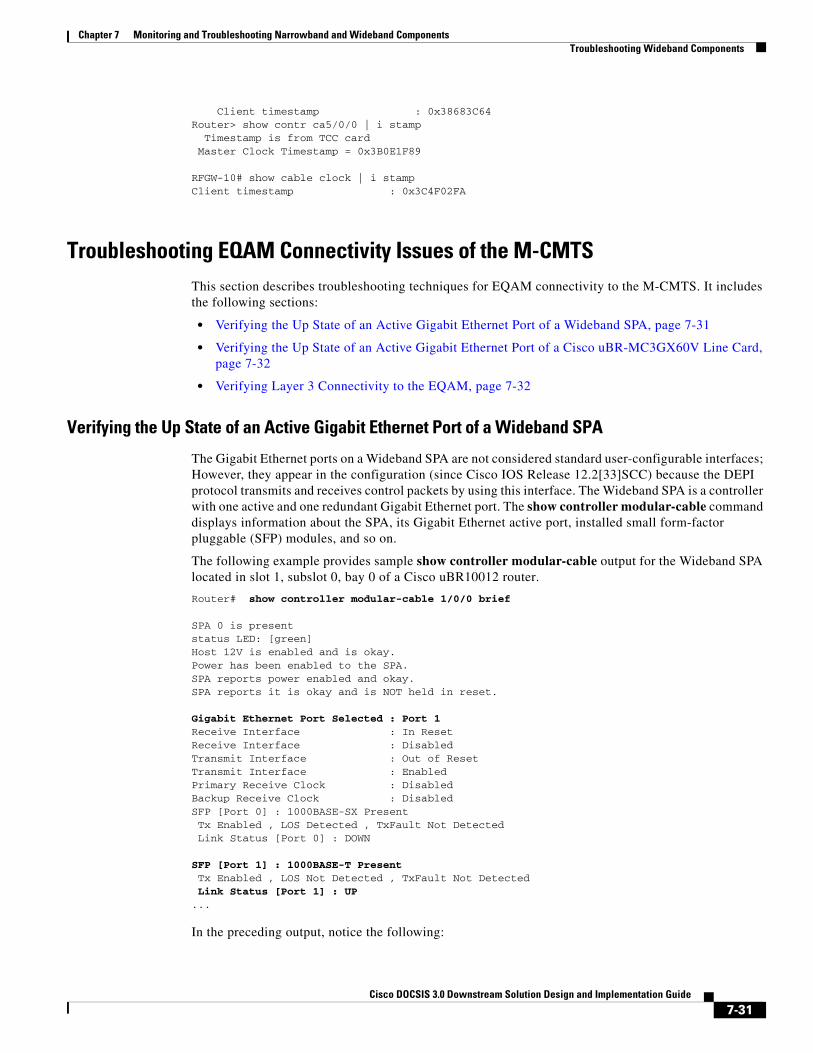
Chapter 7 Monitoring and Troubleshooting Narrowband and Wideband Components Troubleshooting Wideband Components
Client timestamp : 0x38683C64Router> show contr ca5/0/0 | i stamp Timestamp is from TCC card Master Clock Timestamp = 0x3B0E1F89
RFGW-10# show cable clock | i stampClient timestamp : 0x3C4F02FA
Troubleshooting EQAM Connectivity Issues of the M-CMTSThis section describes troubleshooting techniques for EQAM connectivity to the M-CMTS. It includes the following sections:
• Verifying the Up State of an Active Gigabit Ethernet Port of a Wideband SPA, page 7-31
• Verifying the Up State of an Active Gigabit Ethernet Port of a Cisco uBR-MC3GX60V Line Card, page 7-32
• Verifying Layer 3 Connectivity to the EQAM, page 7-32
Verifying the Up State of an Active Gigabit Ethernet Port of a Wideband SPA
The Gigabit Ethernet ports on a Wideband SPA are not considered standard user-configurable interfaces; However, they appear in the configuration (since Cisco IOS Release 12.2[33]SCC) because the DEPI protocol transmits and receives control packets by using this interface. The Wideband SPA is a controller with one active and one redundant Gigabit Ethernet port. The show controller modular-cable command displays information about the SPA, its Gigabit Ethernet active port, installed small form-factor pluggable (SFP) modules, and so on.
The following example provides sample show controller modular-cable output for the Wideband SPA located in slot 1, subslot 0, bay 0 of a Cisco uBR10012 router.
Router# show controller modular-cable 1/0/0 brief
SPA 0 is presentstatus LED: [green]Host 12V is enabled and is okay.Power has been enabled to the SPA.SPA reports power enabled and okay.SPA reports it is okay and is NOT held in reset.
Gigabit Ethernet Port Selected : Port 1Receive Interface : In ResetReceive Interface : DisabledTransmit Interface : Out of ResetTransmit Interface : EnabledPrimary Receive Clock : DisabledBackup Receive Clock : DisabledSFP [Port 0] : 1000BASE-SX Present Tx Enabled , LOS Detected , TxFault Not Detected Link Status [Port 0] : DOWN
SFP [Port 1] : 1000BASE-T Present Tx Enabled , LOS Not Detected , TxFault Not Detected Link Status [Port 1] : UP ...
In the preceding output, notice the following:
7-31Cisco DOCSIS 3.0 Downstream Solution Design and Implementation Guide

Chapter 7 Monitoring and Troubleshooting Narrowband and Wideband Components Troubleshooting Wideband Components
• The Gigabit Ethernet Port Selected field indicates the active Gigabit Ethernet port.
• For the active Gigabit Ethernet port, the SFP [Port 1] field indicates the type of SFP module that is present.
• For the active Gigabit Ethernet port, the Link Status [Port 1] field indicates whether the link is up.
The Cisco Wideband SPA transmits data in a unidirectional manner only and does not receive data from devices connected to its active Gigabit Ethernet port.
If the link for the active Gigabit Ethernet port is not up, check the following:
• The SFP module is correctly installed and matches the SFP module in the connected device.
• The cables to the Wideband SPA ports are correctly connected to a powered-on device.
• The cables to the Wideband SPA ports are not bent or damaged.
• A hardware failure has not occurred. For information, see the “Performing Basic Power Troubleshooting on a Wideband SIP and Wideband SPA” section on page 7-28.
Use the show controller modular-cable command with the sfp keyword to get more detailed information on the SFP modules installed in the Wideband SPA Gigabit Ethernet ports.
Verifying the Up State of an Active Gigabit Ethernet Port of a Cisco uBR-MC3GX60V Line Card
The Cisco uBR-MC3GX60V line card can have up to six SFPs for its three controllers. To check the presence and link status of the SFPs, use the show controller modular-cable <slot/subslot/controller> sfp command.
If the SFP is not present, the show controller modular-cable <slot/subslot/controller> sfp command output displays:
Router# show controller modular-cable 6/0/0 sfp
SFP in Port1 is NOT PRESENT
If the SFP is present, confirm if the physical port status is Up in the show controller modular-cable <slot/subslot/controller> sfp command output:
Router# show controller modular-cable 6/0/0 sfp
SFP in Port0 is Present. Init status Success TX_DISABLE not set, LOS not detected, TX_FAULT not detected LOS detection supported: no Tx Fault detection supported: noSFP Interrupt Counts: LOS:0, PRES:0, TX_FAULT:0Link Status of the MV88E1146C DS Gige Phy Port: UP <<<——— Physical port status is up
Verifying Layer 3 Connectivity to the EQAM
As of Cisco IOS Release 12.2(33)SCC, DEPI control plane functionality requiring bidirectional communication between the CMTS and the EQAM has been supported. This communication requires a Gigabit Ethernet interface visible to the IOS and hence visible with the show ip interfaces brief command.
Note Only a very small fraction of the Gigabit Ethernet interface bandwidth is actually used by the DEPI protocol.
7-32Cisco DOCSIS 3.0 Downstream Solution Design and Implementation Guide

Chapter 7 Monitoring and Troubleshooting Narrowband and Wideband Components Troubleshooting Wideband Components
Both the Wideband SPA and the Cisco uBR-MC3GX60V line card have one Gigabit Ethernet interface per controller, therefore a Wideband SPA has one such interface and a Cisco uBR-MC3GX60V line card has three interfaces.
With an IP address is configured on the interface in a subnet, that includes the EQAM, the IP address of the EQAM is pingable. This provides a basic verification method of the bidirectional communication between the CMTS and the EQAM.
The following example shows the ping command output of an EQAM from the CMTS through the Gigabit Ethernet port of controller 0 of a Cisco uBR-MC3GX60V line card:
!interface GigabitEthernet5/0/0 ip address 10.31.136.215 255.255.255.0 negotiation auto output-rate 100end
router# show running-config | begin ontroll.*5/0/0
controller Modular-Cable 5/0/0 rf-channel 0 cable downstream channel-id 1 rf-channel 0 frequency 453000000 annex B modulation 256qam interleave 32 rf-channel 0 ip-address 10.31.136.100 mac-address 0022.9084.4e3f depi-remote-id 101111
router# ping 10.31.136.100
Type escape sequence to abort.Sending 5, 100-byte ICMP Echos to 10.31.136.100, timeout is 2 seconds:!!!!!Success rate is 100 percent (5/5), round-trip min/avg/max = 1/9/12 ms
Troubleshooting Primary-Capable Channel DOCSIS SignallingThis section describes troubleshooting techniques for the Primary-capable Channel DOCSIS Signalling. It includes the following sections:
• Verifying MAP, UCD, SYNCs for Primary-Capable Channels, page 7-33
• Verifying MDD Packet Transmit for DOCSIS 3.0 Operations, page 7-34
Verifying MAP, UCD, SYNCs for Primary-Capable Channels
All primary-capable channels of a MAC domain transmit MAPs, UCDs, SYNCs packets downstream. In the case of DOCSIS 3.0 deployments, MDD is also transmitted.
For the MAC domain to transmit the packets, the associated modular-cable or integrated-cable interface must have UP status as shown in the show ip interfaces command output. If the interface is not up, verify the following:
1. The interface has been configured with the cable rf-bandwidth-percent command to have at least 1 percent of bandwidth.
2. The interface has been unshut.
3. The controller parameters are configured. This includes frequency, annex, modulation type, and interleaver.
7-33Cisco DOCSIS 3.0 Downstream Solution Design and Implementation Guide

Chapter 7 Monitoring and Troubleshooting Narrowband and Wideband Components Troubleshooting Wideband Components
4. The CGD configuration has been done in the MAC domain interface using the downstream Modular-cable or downstream integrated-cable command. Multiple configuration lines for primary channels may be used.
5. For modular-cable interfaces, the Gigabit Ethernet SFP is in the UP state (see Verifying the Up State of an Active Gigabit Ethernet Port of a Cisco uBR-MC3GX60V Line Card, page 7-32)
When the modular-cable or integrated cable interface is up, verify that at least one upstream in the MAC domain is up with the show interface <mac domain interface> upstream command.
After the upstream is UP, verify if the MAPs, SYNCs, and UCDs are being transmitted. This can be done at 2 layers:
1. At the MAC domain layer, use the show controller command. Execute the show controllers <MAC domain> upstream <upst ream number> | begin Map Counts command and verify the output to determine if the Map Counts counter is incrementing.
2. At the hardware layer, use the show controller <modular-cable | integrated-cable> <slot/subslot/controller> counters rf command. Verify the output to determine if the MAP Pkts counter is incrementing. Verify if the SYNC Pkts counter is incrementing. Without any Layer 3 traffic, the Mbps rate for one upstream channel is approximately 0.9 to 1.0 Mbps. The Mbps rate for four upstreams is approximately 1.7 to 1.9 Mbps.
Verifying MDD Packet Transmit for DOCSIS 3.0 Operations
To support downstream and upstream bonding, the fiber node or fiber nodes in use by a MAC domain must be properly configured. The fiber node is used to calculate the correct downstream service groups and upstream service group IDs placed in the MDD packets. The fiber node configuration includes specifying the downstream channels and the upstream connector in use. The downstream channels must not have frequency or downstream channel ID conflicts.
The following example shows an invalid fiber node:
router# show running | begin fiber.*224
cable fiber-node 224 downstream Modular-Cable 5/0/2 rf-channel 8-11 20-23!router# show cable fiber 224
---------------------------------------------------------------------------------Fiber-Node 224 Channel(s) : downstream Modular-Cable 5/0/2: 8-11 20-23 Channel ID(s): 57, 58, 59, 60, 69, 70, 71, 72 FN Config Status: Configured (status flags = 0x41) MDD Status: Invalid No US Connector Configured
Use the show controller <MAC domain> | begin MDD command to check the number of MDD packets being transmitted. The following example shows that no MDD packets are transmitted:
router# show contr ca5/0/12 | beg MDD MDDs Primary Non-Primary ---------------------------------------------- ----------------------------------------------
7-34Cisco DOCSIS 3.0 Downstream Solution Design and Implementation Guide

Chapter 7 Monitoring and Troubleshooting Narrowband and Wideband Components Troubleshooting Wideband Components
Use the show cable mac-domain <MAC domain> downstream-service-group command to examine the downstream service groups for the MAC domain. The following example shows that there is no service group configured since the fiber node is invalid.
router# show cable mac-domain ca5/0/12 downstream-service-group
Cable MD-DS-SG RFIF Id Resource Chan Primary ChanC5/0/12
Completing the fiber node configuration with an upstream connector resolves the service group, which in turn allows the MAC domain to transmit MDD packets. The following example shows the above debug commands after a connector is configured in the fiber node causing it to be valid which in turn causes the service groups to be calculated and MDD packets to be transmitted and counted in the controller.
router# conf t Enter configuration commands, one per line. End with CNTL/Z.router(config)#cable fiber 224router(config-fiber-node)# upstream cable 5/0 connector 12router(config-fiber-node)# endFiber node 224 is valid.
router# show run | begin fiber.*224
cable fiber-node 224 downstream Modular-Cable 5/0/2 rf-channel 8-11 20-23 upstream Cable 5/0 connector 12
router# show cable fiber 224 ---------------------------------------------------------------------------------Fiber-Node 224 Channel(s) : downstream Modular-Cable 5/0/2: 8-11 20-23 Channel ID(s): 57, 58, 59, 60, 69, 70, 71, 72 upstream Cable 5/0: 12 FN Config Status: Configured (status flags = 0x01) MDD Status: Valid
router# show cable mac-domain ca5/0/12 downstream-service-group
Cable MD-DS-SG RFIF Id Resource Chan Primary ChanC5/0/12 1 5/0/2 08-11 8 9 10 11 20-23
router# show controllers ca5/0/12 | begin MDD
MDDs Primary Non-Primary ---------------------------------------------- 5/0/2:8 36 0 5/0/2:9 36 0 5/0/2:10 36 0 5/0/2:11 36 0 5/0/2:20 0 35 5/0/2:21 0 35 5/0/2:22 0 35 5/0/2:23 0 35 ----------------------------------------------
7-35Cisco DOCSIS 3.0 Downstream Solution Design and Implementation Guide

Chapter 7 Monitoring and Troubleshooting Narrowband and Wideband Components Troubleshooting Wideband Components
Troubleshooting Wideband SIP and Wideband SPAs
Verifying That a Wideband SPA Is Correctly Configured for SPA-to-EQAM Communications
If a Wideband SPA is unable to communicate with an edge QAM device, check that the RF channels configured with the rf-channel command match the values required by the edge QAM device. You can use the show hw-module bay command to see the values that have been configured for an RF channel:
Router# show hw-module bay 1/0/0 config rf-channel 0 verbose
SPA : Wideband-Cable 1/0/0RF channel number : 0 Frequency : 699000000 HzModulation : 64qamAnnex : BIP address of next hop : 192.168.200.30MAC address of EQAM : 000c.3033.2cbfUDP port number : 49152EQAM headroom : 0
Check that the following values are correct and match what is configured on the edge QAM device:
• Frequency—Center frequency used for this RF channel.
• IP address of next hop—IP address of the edge QAM device for this RF channel.
• MAC address—MAC address of the next-hop or edge QAM device for this RF channel.
• DEPI Remote ID—DEPI ID of the RF channel on the EQAM. The DEPI ID is seen with the non-verbose form of this command.
• UDP port—UDP port number for the QAM output port for this RF channel.
If any of the above values do not match what is present on the edge QAM device, the Wideband SPA will not be able to successfully communicate with that device.
On the Cisco uBR10012 router, RF channels are configured with the rf-channel command. The values on the edge QAM are device-specific and are typically configured when setting up the edge QAM device.
Verifying That a Wideband SPA Is Able to Communicate with the Edge QAM Device
To verify that a Wideband SPA that has been correctly configured for wideband operations is communicating with the edge QAM device, use the show hw-module bay command with the counters and rf-channel keywords. In the following example, only RF channels 0 to 3 on the Wideband SPA are transmitting MPEG packets.
Router# show hw-module bay 1/0/0 counters rf-channel
SPA RF channel MPEG packets tx Sync Tx MP Pkts Tx1/0/0 0 109382989 18858822 901215031/0/0 1 109314434 18858822 901212031/0/0 2 0 0 01/0/0 3 0 0 01/0/0 4 0 0 01/0/0 5 0 0 01/0/0 6 0 0 01/0/0 7 0 0 01/0/0 8 0 0 01/0/0 9 0 0 01/0/0 10 0 0 01/0/0 11 0 0 0
7-36Cisco DOCSIS 3.0 Downstream Solution Design and Implementation Guide

Chapter 7 Monitoring and Troubleshooting Narrowband and Wideband Components Troubleshooting Wideband Components
1/0/0 12 0 0 01/0/0 13 0 0 01/0/0 14 0 0 01/0/0 15 0 0 01/0/0 16 0 0 01/0/0 17 0 0 01/0/0 18 0 0 01/0/0 19 0 0 01/0/0 20 0 0 01/0/0 21 0 0 0
Troubleshooting Wideband Channels This section describes troubleshooting techniques for wideband channels. It includes the following sections:
• Verifying That a Wideband Channel Is Up and Is Transmitting Packets, page 7-37
• Verifying That a Wideband Channel Is Configured Correctly, page 7-38
For information about configuring wideband channels, see the Cisco uBR10012 Universal Broadband Router SIP and SPA Software Configuration Guide.
Verifying That a Wideband Channel Is Up and Is Transmitting Packets
To verify that a wideband channel is up and transmitting packets, use the show interface wideband-cable command and examine the first line of the output and the packets output field:
Router# show interface wideband-cable 1/0/0:1
Wideband-Cable1/0/0:1 is up, line protocol is up Hardware is Wideband CMTS Cable interface, address is 0012.001a.8897 (bia 0012.001a.8897) MTU 1500 bytes, BW 74730 Kbit, DLY 1000 usec, reliability 255/255, txload 1/255, rxload 1/255 Encapsulation MCNS, loopback not set Keepalive set (10 sec) ARP type: ARPA, ARP Timeout 04:00:00 Last input never, output 00:00:09, output hang never Last clearing of "show interface" counters never Input queue: 0/75/0/0 (size/max/drops/flushes); Total output drops: 0 Queueing strategy: fifo Output queue: 0/40 (size/max) 30 second input rate 0 bits/sec, 0 packets/sec 30 second output rate 0 bits/sec, 0 packets/sec 0 packets input, 0 bytes, 0 no buffer Received 0 broadcasts, 0 runts, 0 giants, 0 throttles 0 input errors, 0 CRC, 0 frame, 0 overrun, 0 ignored, 0 abort 24224 packets output, 1222002 bytes, 0 underruns 0 output errors, 0 collisions, 0 interface resets 0 output buffer failures, 0 output buffers swapped out
For information on what criteria are used to determine whether a wideband channel and its associated line protocol are up, see the “show interface wideband-cable” section on page 7-14.
7-37Cisco DOCSIS 3.0 Downstream Solution Design and Implementation Guide

Chapter 7 Monitoring and Troubleshooting Narrowband and Wideband Components Troubleshooting Wideband Components
Verifying That a Wideband Channel Is Configured Correctly
To verify whether a wideband channel is configured correctly, use the show hw-module bay command with the wideband-channel keyword and the association, config, or mapping keywords. The following examples show the output for the association keyword:
Router# show hw-module bay 1/0/0 association wideband-channel 0
WB BG Bundle NB NB chan Reserved Availchannel ID num channel ID CIR CIRWideband-Cable1/0/0:0 24 123 Cable5/0/1 120 0 0
In the preceding output, the Bundle num field indicates the virtual bundle interface to which the wideband channel belongs. For a description of each field in the preceding output, see the “show hw-module bay and show controller” section on page 7-16.
The wideband channel and the primary downstream channel (NB channel) must be members of the same virtual bundle interface. The CMTS running configuration file shows the virtual bundle (cable bundle) for the primary downstream channel (Cable5/0/1):
interface Cable5/0/1 no ip address load-interval 30 no cable packet-cache cable bundle 123 cable downstream channel-id 120...
The downstream modular-cable rf-channel command specifies the RF channels that are available for wideband channels on a fiber node. If a wideband channel attempts to use an RF channel that has not been made available for use on the fiber node, a misconfiguration error occurs. In this case, the show hw-module bay command displays the following error message:
Router# show hw-module bay 1/0/0 association wideband-channel
WB BG Bundle NB NB chan Reserved Availchannel ID num channel ID CIR CIRWideband-Cable1/0/0:0 RF channel mismatch with Fiber Node 1
The following example shows the show hw-module bay command output for the config keyword:
Router# show hw-module bay 1/0/0 config wideband-channel
WB BG Bundle WB Host Primary channel ID num Slot/Subslot BG Wideband-Cable1/0/0:0 24 123 5/0 Yes Wideband-Cable1/0/0:1 25 123 5/0 Yes Wideband-Cable1/0/0:2 26 123 5/0 Yes Wideband-Cable1/0/0:3 27 123 5/0 Yes Wideband-Cable1/0/0:4 28 123 5/0 Yes Wideband-Cable1/0/0:5 29 123 5/0 Yes Wideband-Cable1/0/0:6 30 123 5/0 Yes Wideband-Cable1/0/0:7 31 123 5/0 Yes Wideband-Cable1/0/0:8 32 0 5/0 Yes Wideband-Cable1/0/0:9 33 0 5/0 Yes Wideband-Cable1/0/0:10 34 0 5/0 Yes Wideband-Cable1/0/0:11 35 0 5/0 Yes
In the preceding output, each wideband channel that is used should be configured as a member of a virtual bundle interface. Channels 8 through 11 are not members of a virtual bundle interface.
The following example shows the show hw-module bay command output for the mapping keyword:
7-38Cisco DOCSIS 3.0 Downstream Solution Design and Implementation Guide

Chapter 7 Monitoring and Troubleshooting Narrowband and Wideband Components Troubleshooting Wideband Components
Router# show hw-module bay 1/0/0 mapping wideband-channel
SPA WB RF BW % channel channel1/0/0 0 0 100 1 100 1/0/0 1 2 100 3 100 1/0/0 2 4 100 5 100 1/0/0 3 6 100 7 100 1/0/0 4 8 100 9 100 1/0/0 5 10 100 11 100 1/0/0 6 12 100 13 100 1/0/0 7 14 100 15 100 1/0/0 8 16 100 17 100 1/0/0 9 18 100 19 100 1/0/0 10 20 100 21 100 1/0/0 11 22 100 23 100
A channel-bonded wideband channel is associated with at least two RF channels depending on the wideband channel configuration. The cable rf-channel command associates an RF channel with a wideband channel. The bandwidth percent (BW %) of each RF channel used for the wideband channel is 100 percent by default, but is configurable with the cable rf-channel command.
Troubleshooting Wideband Cable Modems This section describes troubleshooting techniques for wideband cable modems. It includes the following sections:
• Pinging a Wideband Cable Modem, page 7-39
• Verifying That a Wideband-Capable Cable Modem Is Registered as a Wideband Modem, page 7-40
• Examining Wideband-Capable Modems That are Partial Online, page 7-41
• Verifying Other Information for Wideband Cable Modems, page 7-41
Pinging a Wideband Cable Modem
To determine whether a wideband cable modem or any DOCSIS cable CPE device is reachable from the CMTS at the DOCSIS MAC layer, use the ping docsis command with either a MAC address or IP address:
Router# ping docsis 1.11.0.5
Queueing 5 MAC-layer station maintenance intervals, timeout is 25 msec:!!!!!Success rate is 100 percent (5/5)
7-39Cisco DOCSIS 3.0 Downstream Solution Design and Implementation Guide

Chapter 7 Monitoring and Troubleshooting Narrowband and Wideband Components Troubleshooting Wideband Components
The ping docsis command uses 1/64—the bandwidth of IP ping—and works with cable modems that have not yet acquired an IP address. This allows you to ping cable modems that are unable to complete registration, that have internal bugs, or that are unresponsive due to a crash.
The ping docsis command with the verbose keyword includes a real-time view and plot of requested power adjustments, frequency, timing offset adjustments, and a measure of optimal headend reception power.
Router# ping docsis 1.11.0.5 verbose
Queueing 5 MAC-layer station maintenance intervals, timeout is 25 msec:Reply from 0014.bfbe.3e3c: 46 ms, tadj=1, padj=0, fadj=34Reply from 0014.bfbe.3e3c: 46 ms, tadj=0, padj=0, fadj=26Reply from 0014.bfbe.3e3c: 50 ms, tadj=0, padj=0, fadj=29Reply from 0014.bfbe.3e3c: 50 ms, tadj=1, padj=0, fadj=29Reply from 0014.bfbe.3e3c: 50 ms, tadj=-1, padj=0, fadj=39
Success rate is 100 percent (5/5)
For more information on the ping docsis command, see the Cisco Broadband Cable Command Reference Guide.
Verifying That a Wideband-Capable Cable Modem Is Registered as a Wideband Modem
To verify that a wideband-capable cable modem is registered as a wideband modem, use the show cable modem command. In the following example, the MAC address of the wideband cable modem is specified:
Router# show cable modem 0014.bfbe.3e70
MAC Address IP Address I/F MAC Prim RxPwr Timing Num BPI State Sid (dBmv) Offset CPE Enb0014.bfbe.3e70 1.11.0.3 C5/0/1/U0 w-online(pt) 1 0.00 1231 0 Y
If a wideband-capable cable modem is registered as a wideband modem, the MAC State field will have one of the w-online values (wideband-online), such as w-online(pt) in the preceding example. For descriptions of the complete set of MAC state values, see the show cable modem command in the Cisco Broadband Cable Command Reference Guide.
A wideband-capable modem may also register as a DOCSIS 2.0 modem (for example, if a wideband channel is not available). In this case, the MAC State field displayed by the show cable modem command will not have one of the w-online values.
To determine the set of wideband-capable cable modems that have registered as wideband modems on the CMTS, use the show cable modem wideband command:
Router# show cable modem wideband
MAC Address IP Address I/F MAC Prim BG DSID MD-DS-SG State Sid ID0014.bfbe.3e70 1.11.0.3 C5/0/1/U0 w-online(pt) 1 24 24 N/A0014.bfbe.3e3c 1.11.0.4 C5/0/1/U0 w-online(pt) 2 24 24 N/A0016.92fb.5742 1.11.0.6 C5/0/1/U0 w-online(pt) 3 24 256 1 0016.92fb.580e 1.11.0.7 C5/0/1/U0 w-online(pt) 4 24 264 1 0014.bfbe.3eaa 1.11.0.2 C6/0/1/U0 w-online(pt) 7 36 36 N/A0016.92fb.57f8 1.11.0.5 C6/0/1/U0 w-online(pt) 8 36 298 1 0016.92fb.57f4 1.11.0.8 C6/0/1/U0 w-online(pt) 9 36 306 1
To determine the set of wideband-capable cable modems that have registered as DOCSIS 2.0 modems on the CMTS, use the show cable modem wideband command with the registered-traditional-docsis keyword.
7-40Cisco DOCSIS 3.0 Downstream Solution Design and Implementation Guide

Chapter 7 Monitoring and Troubleshooting Narrowband and Wideband Components Troubleshooting Wideband Components
Examining Wideband-Capable Modems That are Partial Online
A fault in one or more channels in the CMTS or cable plant may result in a wideband modem being partial online. DOCSIS 3.0 includes signaling based on the CM-STATUS message that enables modems to inform the CMTS about downstream failures. The CMTS will track and react upon these messages. The CMTS may disable an RF channel in a wideband channel, causing the modems to go into partial online mode, p-online. The show cable modem partial command can used to view all modems in the p-online state.
To determine the cause of the partial online status, use the show cable modem <address> wideband rcs-status command for a modem in p-online mode. Failures reported by the modem will be counted categorically. For example:
Router # show cable modem 50.3.81.80 wideband rcs-status
CM : 0025.2e2d.74b8RF : 5/0/2 8 Status : UP FEC/QAM Failure : 0 Dup FEC/QAM Failure : 0 FEC/QAM Recovery : 0 Dup FEC/QAM Recovery : 0 MDD Failure : 0 Dup MDD Failure : 0 MDD Recovery : 0 Dup MDD Recovery : 4 Flaps : 0 Flap Duration : 00:00RF : 5/0/2 10 Status : UP FEC/QAM Failure : 0 Dup FEC/QAM Failure : 0 FEC/QAM Recovery : 0 Dup FEC/QAM Recovery : 0 MDD Failure : 0 Dup MDD Failure : 0 MDD Recovery : 0 Dup MDD Recovery : 0 Flaps : 0 Flap Duration : 00:00
The type of error reported can then be used to further troubleshoot the problem on the CMTS, the EQAM or the cable plant.
Verifying Other Information for Wideband Cable Modems
To verify other information related to wideband cable modems, use the show commands that display information relevant to all cable modems:
• show cable modem access-group—Displays information about the access group for each cable modem.
• show cable modem classifiers—Displays information about the classifiers used for each cable modem.
• show cable modem cnr—Displays carrier-to-noise ratio (CNR) information for cable modems that are using cable interface line cards with hardware spectrum-management capabilities.
7-41Cisco DOCSIS 3.0 Downstream Solution Design and Implementation Guide

Chapter 7 Monitoring and Troubleshooting Narrowband and Wideband Components Troubleshooting Gigabit Ethernet Components
• show cable modem connectivity—Displays connectivity information for each cable modem.
• show cable modem counters—Displays traffic counters for each cable modem.
• show cable modem cpe—Displays information about the CPE devices using each cable modem.
• show cable modem errors—Displays packet error information for each cable modem.
• show cable modem flap—Displays flap-list information for each cable modem.
• show cable modem mac—Displays MAC-layer information for each cable modem.
• show cable modem maintenance—Displays information about the Station Maintenance errors for each cable modem.
• show cable modem offline—Lists the offline cable modems.
• show cable modem phy—Displays the PHY layer information for each cable modem.
• show cable modem qos—Displays the quality of service (QoS) information for each cable modem.
• show cable modem registered—Lists the registered cable modems.
• show cable modem remote-query—Displays information collected by the remote-query feature.
• show cable modem rogue—Displays a list of cable modems that have been marked, locked, or rejected because they failed the dynamic shared-secret authentication checks.
• show cable modem summary—Displays summary information about the cable modems on each cable interface.
• show cable modem unregistered—Lists the unregistered cable modems.
• show cable modem vendor—Displays vendor names and identifies each cable modem.
For information on these commands, see the Cisco Broadband Cable Command Reference Guide.
Troubleshooting Gigabit Ethernet ComponentsThis section provides basic information for troubleshooting the Gigabit Ethernet components of the Cisco DOCSIS 3.0 Downstream Solution:
• Troubleshooting the Cisco SIP-600, page 7-42
• Troubleshooting the Gigabit Ethernet SPAs, page 7-42
Troubleshooting the Cisco SIP-600The troubleshooting techniques adopted for the Cisco SIP-600 is similar to what is used for a Cisco Wideband SIP. For more information, see the chapter “Troubleshooting the SIPs” in the Cisco uBR10012 Universal Broadband Router SIP and SPA Software Configuration Guide.
Troubleshooting the Gigabit Ethernet SPAsFor detailed troubleshooting information on Gigabit Ethernet SPAs, see the chapter “Troubleshooting Gigabit Ethernet SPAs” in the Cisco uBR10012 Universal Broadband Router SIP and SPA Software Configuration Guide.
7-42Cisco DOCSIS 3.0 Downstream Solution Design and Implementation Guide

Cisco DOCSIS 3.0 Downstream
A
P P E N D I X 1
Cisco DOCSIS 3.0 Downstream Solution, Component Compatibility MatrixTable 1-1 and Table 1-2 summarizes the compatibility of Cisco DOCSIS 3.0 Downstream Solution components with the Cisco IOS software functionality supported in the following major releases of the solution:
• Cisco DOCSIS 3.0 Downstream Solution (Cisco IOS Release 12.2(33)SCH and later releases)
Yes—Indicates that the component is compatible with the solution release and provides full support for the release features and functionality.
No—Indicates that the component is not compatible with the solution release and does not provide full support for the release features and functionality. See the Notes column for more information.
Table 1-1 indicates the matrix for unicast with secondary Wideband interface with DOCSIS Baseline Privacy Interface (BPI) feature:
Table 1-1 Compatibility Matrix for Primary Downstreams and Wideband Interfaces for Unicast
on Secondary Wideband Interface with BPI Configuration
Primary Downstream Interface and Wideband Interface
Cisco UBR-MC20X20V1
1. The Cisco UBR-MC20X20V cable interface line card has three variants: Cisco UBR-MC20X20V-0D, Cisco UBR-MC20X20V-5D, and Cisco UBR-MC20X20V-20D. The Cisco UBR-MC20X20V-0D line card supports 20 upstreams and zero (no) downstreams. The Cisco UBR-MC20X20V-5D line card supports 20 upstreams and 5 downstreams, and the Cisco UBR-MC20X20V-20D line card supports 20 upstreams and 20 downstreams.
Cisco UBR-MC3GX60V2
2. The Cisco uBR-MC3GX60V line card is supported with PRE4 and PRE5.
Cisco Wideband SPA and Cisco UBR-MC20X20V MAC Domain Interface
Cisco Wideband SPA and Cisco UBR-MC3GX60V MAC Domain Interface
Secondary Cisco Wideband Interface
Cisco UBR-MC20X20V
Yes Yes Yes Yes
Cisco UBR-MC3GX60V
Yes Yes Yes Yes
Cisco Wideband SPA
Yes Yes No No
1-1 Solution Design and Implementation Guide

Appendix 1 Cisco DOCSIS 3.0 Downstream Solution, Component Compatibility Matrix
Table 1-2 indicates the matrix for static multicast on remote Wideband interface without BPI configuration:
Table 1-3 summarizes the compatibility of Cisco DOCSIS 3.0 Downstream Solution components with the Cisco IOS software functionality supported in the following major releases of the solution:
• Cisco Wideband Cable Solution, Release 1.0 (Cisco IOS Release 12.3[21]BC and Cisco IOS Release 12.3[21a]BC3)
• Cisco DOCSIS 3.0 Downstream Solution (Cisco IOS Release 12.3[23]BC and Cisco IOS Release 12.2[33]SCB (and later releases))
In Table 1-3, the following applies:
Yes—Indicates that the component is compatible with the solution release and provides full support for the release features and functionality.
No—Indicates that the component is not compatible with the solution release and does not provide full support for the release features and functionality. See the Notes column for more information.
Table 1-2 Compatibility Matrix for Primary Downstreams and Wideband Interfaces for Static
Multicast on Remote Wideband Interface without BPI (Unencrypted) Configuration
Primary Downstream Interface and Wideband Interface
Cisco UBR-MC20X20V1
1. The Cisco UBR-MC20X20V cable interface line card has three variants: Cisco UBR-MC20X20V-0D, Cisco UBR-MC20X20V-5D, and Cisco UBR-MC20X20V-20D. The Cisco UBR-MC20X20V-0D line card supports 20 upstreams and zero (no) downstreams. The Cisco UBR-MC20X20V-5D line card supports 20 upstreams and 5 downstreams, and the Cisco UBR-MC20X20V-20D line card supports 20 upstreams and 20 downstreams.
Cisco UBR-MC3GX60V2
2. The Cisco uBR-MC3GX60V line card is supported with PRE4 and PRE5.
Cisco Wideband SPA and Cisco UBR-MC20X20V MAC Domain Interface
Cisco Wideband SPA and Cisco UBR-MC3GX60V MAC Domain Interface
Remote Wideband Interface
Cisco UBR-MC20X20V
Yes Yes Yes Yes
Cisco UBR-MC3GX60V
Yes Yes Yes Yes
Cisco Wideband SPA
Yes Yes Yes Yes
1-2Cisco DOCSIS 3.0 Downstream Solution Design and Implementation Guide

Appendix 1 Cisco DOCSIS 3.0 Downstream Solution, Component Compatibility Matrix
Table 1-3 Component-compatibility
Solution Component
Cisco Cable Wideband Solution, Cisco IOS Releases 12.3(21)BC & 12.3(21a)BC3
Cisco DOCSIS 3.0 Downstream Solution, Cisco IOS Release 12.3(23)BC
Cisco DOCSIS 3.0 Downstream Solution, Cisco IOS Release 12.2(33)SCB and later releases Notes
Performance Routing Engine 2 (PRE2)
Yes Yes Yes
Performance Routing Engine 4 (PRE4)
No No Yes Required for the 1-port 10 Gigabit Ethernet SPA
Performance Routing Engine 5 (PRE5)
No No Yes Introduced in Cisco IOS Release 12.2(33)SCH
Cisco UBR-MC20X20V cable line card
No No Yes Introduced in Cisco IOS Release 12.2(33)SCC
Cisco uBR-MC3GX60V line card
No No Yes Introduced in Cisco IOS Release 12.2(33)SCE
Cisco Wideband SIP Yes Yes Yes
Cisco Wideband SPA Yes Yes Yes
Cisco 3 Gbps Wideband Shared Port Adapter
Yes Yes Yes Introduced in Cisco IOS Release 12.2(33)SCH
Cisco 6 Gbps Wideband Shared Port Adapter
Yes Yes Yes Introduced in Cisco IOS Release 12.2(33)SCI
Cisco 10000 SPA Interface Processor-600
No No Yes The Cisco Wideband SIP and the Cisco SIP-600 cannot coexist on a Cisco uBR10012 router
Cisco 5-port Gigabit Ethernet SPA
No No Yes
Cisco 1-port 10 Gigabit Ethernet SPA
No No Yes
1-3Cisco DOCSIS 3.0 Downstream Solution Design and Implementation Guide

Appendix 1 Cisco DOCSIS 3.0 Downstream Solution, Component Compatibility Matrix
Timing, Communication, and Control Plus card (TCC+)
Yes No Yes Will work with Cisco IOS Release 12.3(23)BC, but does not support a DOCSIS timing server.
DOCSIS Timing and Control Card (DTCC)
Yes Yes Yes
Linksys WCM300-NA, Linksys JP, and WCM300-EURO modems
Yes Yes No
Scientific Atlanta DPC2505 and EPC2505 modems
Yes Yes Yes
Scientific Atlanta DPC3000 and DPC3010 modems
Yes Yes Yes
Scientific Atlanta Continuum DVP XDQA24 EQAM device
Yes Yes Yes
Harmonic NSG 9116 EQAM device
Yes No Yes
Harmonic NSG 9000 EQAM device
Yes Yes Yes
Vecima Networks VistaLynx VL1000 EQAM device
Yes No Yes
Cisco RF Gateway 1 Yes Yes Yes
Cisco RF Gateway 10 Yes Yes Yes
Table 1-3 Component-compatibility (continued)
Solution Component
Cisco Cable Wideband Solution, Cisco IOS Releases 12.3(21)BC & 12.3(21a)BC3
Cisco DOCSIS 3.0 Downstream Solution, Cisco IOS Release 12.3(23)BC
Cisco DOCSIS 3.0 Downstream Solution, Cisco IOS Release 12.2(33)SCB and later releases Notes
1-4Cisco DOCSIS 3.0 Downstream Solution Design and Implementation Guide