Embed Size (px)
Citation preview
© 2017 Cisco and/or its affiliates. All rights reserved. This document is Cisco Public Information. Page 1 of 53
White Paper
Cisco ACI Multi-Site Architecture
© 2017 Cisco and/or its affiliates. All rights reserved. This document is Cisco Public Information. Page 2 of 53
Contents
Introduction .............................................................................................................................................................. 3
Cisco ACI Multi-Site architecture ........................................................................................................................... 6 Cisco ACI Multi-Site policy manager ..................................................................................................................... 9
Cisco ACI Multi-Site deployment considerations ............................................................................................ 12 Cisco ACI Multi-Site use cases ........................................................................................................................... 14
Layer 3–only connectivity across sites ........................................................................................................... 14 Layer 2 connectivity across sites without flooding .......................................................................................... 17 Layer 2 connectivity across sites with flooding ............................................................................................... 20
Intersite connectivity deployment considerations ................................................................................................ 22 Multi-Site overlay control plane ........................................................................................................................... 24 Multi-Site overlay data plane ............................................................................................................................... 27
Layer 2 BUM traffic handling across sites ...................................................................................................... 27 Intrasubnet unicast communication across sites ............................................................................................ 30 Intersubnet unicast communication across sites ............................................................................................ 32
Connectivity to the external Layer 3 domain ....................................................................................................... 34 Multi-Site and traditional L3Out connections on border leaf nodes ................................................................ 36 Multi-Site and GOLF L3Out connections ........................................................................................................ 39
Virtual machine manager integration models ...................................................................................................... 42 Multiple virtual machine managers across sites ............................................................................................. 43 Single virtual machine manager across sites ................................................................................................. 44
Migration scenarios ............................................................................................................................................. 45 Creating new policies in the Cisco ACI Multi-Site policy manager.................................................................. 45 Importing existing policies from Cisco APIC into the Cisco ACI Multi-Site policy manager ............................ 46
Deployment best practices .................................................................................................................................. 47 Cisco ACI Multi-Site cluster deployment ........................................................................................................ 47 Day-0 Multi-Site infrastructure configuration .................................................................................................. 48 General best practices for Cisco ACI Multi-Site design .................................................................................. 50
Conclusion ............................................................................................................................................................. 52
For more information ............................................................................................................................................. 53
© 2017 Cisco and/or its affiliates. All rights reserved. This document is Cisco Public Information. Page 3 of 53
Introduction
With the increasing adoption of Cisco® Application Centric Infrastructure (Cisco ACI
™) as pervasive fabric
technology, enterprises and service providers commonly need to interconnect separate Cisco ACI fabrics.
Business requirements (business continuance, disaster avoidance, etc.) lead to the deployment of separate data
center fabrics, and these need to be interconnected with each other. Depending on the deployment option used
(and as explained in this document), these fabrics may be called pods or fabrics and sites.
Note: To best understand the design presented in this document, readers should have at least a basic
understanding of Cisco ACI and how it works and is designed for operation in a single site or pod. For more
information, see the Cisco ACI white papers available at the following link:
https://www.cisco.com/c/en/us/solutions/data-center-virtualization/application-centric-infrastructure/white-paper-
listing.html.
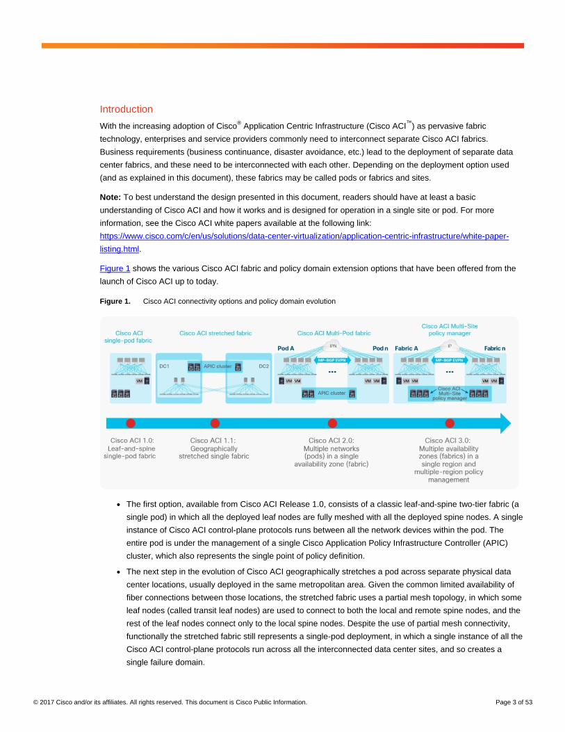
Figure 1 shows the various Cisco ACI fabric and policy domain extension options that have been offered from the
launch of Cisco ACI up to today.
Figure 1. Cisco ACI connectivity options and policy domain evolution
● The first option, available from Cisco ACI Release 1.0, consists of a classic leaf-and-spine two-tier fabric (a
single pod) in which all the deployed leaf nodes are fully meshed with all the deployed spine nodes. A single
instance of Cisco ACI control-plane protocols runs between all the network devices within the pod. The
entire pod is under the management of a single Cisco Application Policy Infrastructure Controller (APIC)
cluster, which also represents the single point of policy definition.
● The next step in the evolution of Cisco ACI geographically stretches a pod across separate physical data
center locations, usually deployed in the same metropolitan area. Given the common limited availability of
fiber connections between those locations, the stretched fabric uses a partial mesh topology, in which some
leaf nodes (called transit leaf nodes) are used to connect to both the local and remote spine nodes, and the
rest of the leaf nodes connect only to the local spine nodes. Despite the use of partial mesh connectivity,
functionally the stretched fabric still represents a single-pod deployment, in which a single instance of all the
Cisco ACI control-plane protocols run across all the interconnected data center sites, and so creates a
single failure domain.
© 2017 Cisco and/or its affiliates. All rights reserved. This document is Cisco Public Information. Page 4 of 53
Note: For more information about the Cisco ACI stretched-fabric deployment option, refer to the following
link: https://www.cisco.com/c/en/us/td/docs/switches/datacenter/aci/apic/sw/kb/b_kb-aci-stretched-
fabric.html.
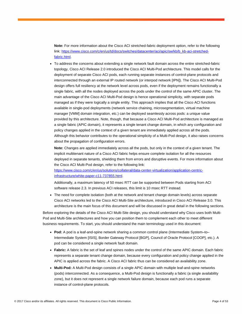
● To address the concerns about extending a single network fault domain across the entire stretched-fabric
topology, Cisco ACI Release 2.0 introduced the Cisco ACI Multi-Pod architecture. This model calls for the
deployment of separate Cisco ACI pods, each running separate instances of control-plane protocols and
interconnected through an external IP routed network (or interpod network [IPN]). The Cisco ACI Multi-Pod
design offers full resiliency at the network level across pods, even if the deployment remains functionally a
single fabric, with all the nodes deployed across the pods under the control of the same APIC cluster. The
main advantage of the Cisco ACI Multi-Pod design is hence operational simplicity, with separate pods
managed as if they were logically a single entity. This approach implies that all the Cisco ACI functions
available in single-pod deployments (network service chaining, microsegmentation, virtual machine
manager [VMM] domain integration, etc.) can be deployed seamlessly across pods: a unique value
provided by this architecture. Note, though, that because a Cisco ACI Multi-Pod architecture is managed as
a single fabric (APIC domain), it represents a single tenant change domain, in which any configuration and
policy changes applied in the context of a given tenant are immediately applied across all the pods.
Although this behavior contributes to the operational simplicity of a Multi-Pod design, it also raises concerns
about the propagation of configuration errors.
Note: Changes are applied immediately across all the pods, but only in the context of a given tenant. The
implicit multitenant nature of a Cisco ACI fabric helps ensure complete isolation for all the resources
deployed in separate tenants, shielding them from errors and disruptive events. For more information about
the Cisco ACI Multi-Pod design, refer to the following link:
https://www.cisco.com/c/en/us/solutions/collateral/data-center-virtualization/application-centric-
infrastructure/white-paper-c11-737855.html.
Additionally, a maximum latency of 50 msec RTT can be supported between Pods starting from ACI
software release 2.3. In previous ACI releases, this limit is 10 msec RTT instead.
● The need for complete isolation (both at the network and tenant change domain levels) across separate
Cisco ACI networks led to the Cisco ACI Multi-Site architecture, introduced in Cisco ACI Release 3.0. This
architecture is the main focus of this document and will be discussed in great detail in the following sections.
Before exploring the details of the Cisco ACI Multi-Site design, you should understand why Cisco uses both Multi-
Pod and Multi-Site architectures and how you can position them to complement each other to meet different
business requirements. To start, you should understand the main terminology used in this document:
● Pod: A pod is a leaf-and-spine network sharing a common control plane (Intermediate System–to–
Intermediate System [ISIS], Border Gateway Protocol [BGP], Council of Oracle Protocol [COOP], etc.). A
pod can be considered a single network fault domain.
● Fabric: A fabric is the set of leaf and spines nodes under the control of the same APIC domain. Each fabric
represents a separate tenant change domain, because every configuration and policy change applied in the
APIC is applied across the fabric. A Cisco ACI fabric thus can be considered an availability zone.
● Multi-Pod: A Multi-Pod design consists of a single APIC domain with multiple leaf-and-spine networks
(pods) interconnected. As a consequence, a Multi-Pod design is functionally a fabric (a single availability
zone), but it does not represent a single network failure domain, because each pod runs a separate
instance of control-plane protocols.
© 2017 Cisco and/or its affiliates. All rights reserved. This document is Cisco Public Information. Page 5 of 53
● Multi-Site: A Multi-Site design is the architecture interconnecting multiple APIC cluster domains with their
associated pods. A Multi-Site design could also be called a Multi-Fabric design, because it interconnects
separate availability zones (fabrics), each deployed either as a single pod or multiple pods (a Multi-Pod
design).
Note: Do not confuse the term “Multi-Fabric design” used here to identify the Multi-Site architecture
discussed in this document with the term “dual-fabric design,” which refers to a precursor of the Multi-Site
design and is documented at the following link: https://www.cisco.com/c/en/us/solutions/data-center-
virtualization/application-centric-infrastructure/white-paper-c11-737077.html?cachemode=refresh.
An understanding of availability zones is essential to understanding why Cisco decided to invest in a Multi-Site
architecture after having already delivered the Cisco ACI Multi-Pod design. Organizations typically need to deploy
applications across data center fabrics representing separate availability zones. This setup is critical to help ensure
that any network-level failures or configuration or policy definition errors that occur in one availability zone will not
ever be propagated to the application’s workloads running in a separate availability zone, hence essentially
guaranteeing business continuance.
The deployment of Cisco ACI Multi-Pod and Multi-Site architectures thus can be combined to meet two different
requirements. You can create a group of flexible Cisco ACI islands that can be seen and operated as a single
logical entity (fabric) and function using the classic active-active model. You then can also reliably interconnect and
scale those fabrics. See Figure 2.
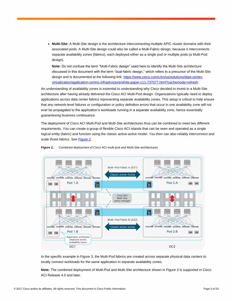
Figure 2. Combined deployment of Cisco ACI multi-pod and Multi-Site architectures
In the specific example in Figure 3, the Multi-Pod fabrics are created across separate physical data centers to
locally connect workloads for the same application in separate availability zones.
Note: The combined deployment of Multi-Pod and Multi-Site architecture shown in Figure 3 is supported in Cisco
ACI Release 4.0 and later.
© 2017 Cisco and/or its affiliates. All rights reserved. This document is Cisco Public Information. Page 6 of 53
The remainder of this document focuses on the Cisco ACI Multi-Site architecture, starting with an overview of its
functional components.
Cisco ACI Multi-Site architecture
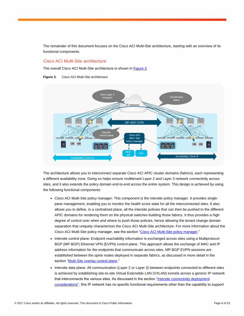
The overall Cisco ACI Multi-Site architecture is shown in Figure 3.
Figure 3. Cisco ACI Multi-Site architecture
The architecture allows you to interconnect separate Cisco ACI APIC cluster domains (fabrics), each representing
a different availability zone. Doing so helps ensure multitenant Layer 2 and Layer 3 network connectivity across
sites, and it also extends the policy domain end-to-end across the entire system. This design is achieved by using
the following functional components:
● Cisco ACI Multi-Site policy manager: This component is the intersite policy manager. It provides single-
pane management, enabling you to monitor the health score state for all the interconnected sites. It also
allows you to define, in a centralized place, all the intersite policies that can then be pushed to the different
APIC domains for rendering them on the physical switches building those fabrics. It thus provides a high
degree of control over when and where to push those policies, hence allowing the tenant change domain
separation that uniquely characterizes the Cisco ACI Multi-Site architecture. For more information about the
Cisco ACI Multi-Site policy manager, see the section “Cisco ACI Multi-Site policy manager.”
● Intersite control plane: Endpoint reachability information is exchanged across sites using a Multiprotocol-
BGP (MP-BGP) Ethernet VPN (EVPN) control plane. This approach allows the exchange of MAC and IP
address information for the endpoints that communicate across sites. MP-BGP EVPN sessions are
established between the spine nodes deployed in separate fabrics, as discussed in more detail in the
section “Multi-Site overlay control plane.”
● Intersite data plane: All communication (Layer 2 or Layer 3) between endpoints connected to different sites
is achieved by establishing site-to-site Virtual Extensible LAN (VXLAN) tunnels across a generic IP network
that interconnects the various sites. As discussed in the section “Intersite connectivity deployment
considerations”, this IP network has no specific functional requirements other than the capability to support
© 2017 Cisco and/or its affiliates. All rights reserved. This document is Cisco Public Information. Page 7 of 53
routing and increased maximum transmission unit (MTU) size (given the overhead from the VXLAN
encapsulation).
The use of site-to-site VXLAN encapsulation greatly simplifies the configuration and functions required for the
intersite IP network. It also allows network and policy information (metadata) to be carried across sites, as shown in
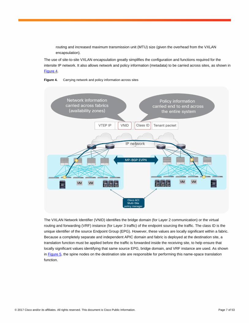
Figure 4.
Figure 4. Carrying network and policy information across sites
The VXLAN Network Identifier (VNID) identifies the bridge domain (for Layer 2 communication) or the virtual
routing and forwarding (VRF) instance (for Layer 3 traffic) of the endpoint sourcing the traffic. The class ID is the
unique identifier of the source Endpoint Group (EPG). However, these values are locally significant within a fabric.
Because a completely separate and independent APIC domain and fabric is deployed at the destination site, a
translation function must be applied before the traffic is forwarded inside the receiving site, to help ensure that
locally significant values identifying that same source EPG, bridge domain, and VRF instance are used. As shown
in Figure 5, the spine nodes on the destination site are responsible for performing this name-space translation
function.
© 2017 Cisco and/or its affiliates. All rights reserved. This document is Cisco Public Information. Page 8 of 53
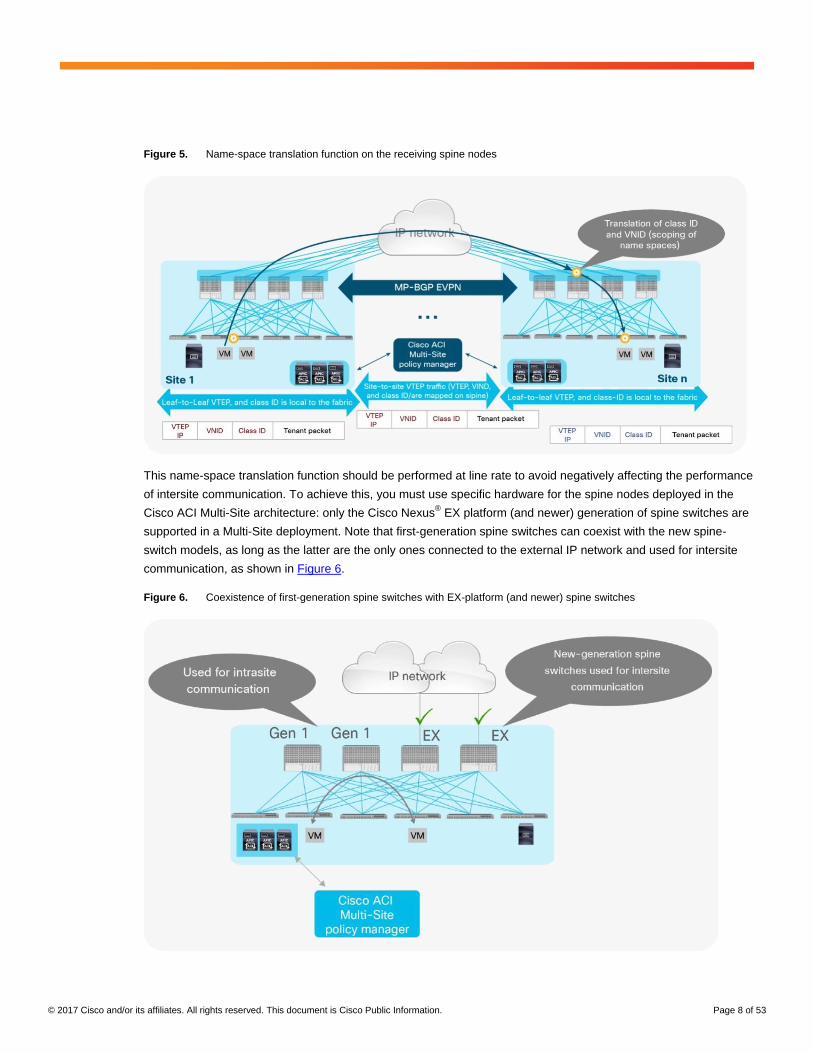
Figure 5. Name-space translation function on the receiving spine nodes
This name-space translation function should be performed at line rate to avoid negatively affecting the performance
of intersite communication. To achieve this, you must use specific hardware for the spine nodes deployed in the
Cisco ACI Multi-Site architecture: only the Cisco Nexus® EX platform (and newer) generation of spine switches are
supported in a Multi-Site deployment. Note that first-generation spine switches can coexist with the new spine-
switch models, as long as the latter are the only ones connected to the external IP network and used for intersite
communication, as shown in Figure 6.
Figure 6. Coexistence of first-generation spine switches with EX-platform (and newer) spine switches
© 2017 Cisco and/or its affiliates. All rights reserved. This document is Cisco Public Information. Page 9 of 53
The specific coexistence scenario shown in Figure 7 also shows that every deployed spine does not need to be
connected to the external Layer 3 domain. You determine the number of spines and links used to connect to the
external IP network based on the specific hardware available and your desired level of resiliency and throughput.
The introduction of the Cisco ACI Multi-Site architecture also allows you to scale up the total number of leaf and
spine nodes deployed across the interconnected fabrics, as well as the total number of endpoints. This capability is
one of the main points of differentiation between Cisco ACI Multi-Site and Multi-Pod designs, because the latter
option is still bound by the scalability restrictions of a single fabric design.
Note: When planning a Cisco ACI deployment, you always should refer to the scalability guides available at
Cisco.com. See the following link for the scalability guide valid for the Cisco ACI Release 3.0, which introduces
support for Cisco ACI Multi-Site design: https://www.cisco.com/c/en/us/td/docs/switches/datacenter/aci/apic/sw/3-
x/verified_scalabilty/b_Verified_Scalability_3_0_1x_and_13_0_1x.html.
Cisco ACI Multi-Site policy manager
The Cisco ACI Multi-Site policy manager is responsible for provisioning, health monitoring, and managing the full
lifecycle of Cisco ACI networking policies and stretched tenant policies across Cisco ACI sites around the world. It
essentially represents the single source of truth for these policies.
The Multi-Site policy manager provides these main functions:
● Create and manage Cisco ACI Multi-Site users and administrators and application of Role-Based Access
Control (RBAC) rules.
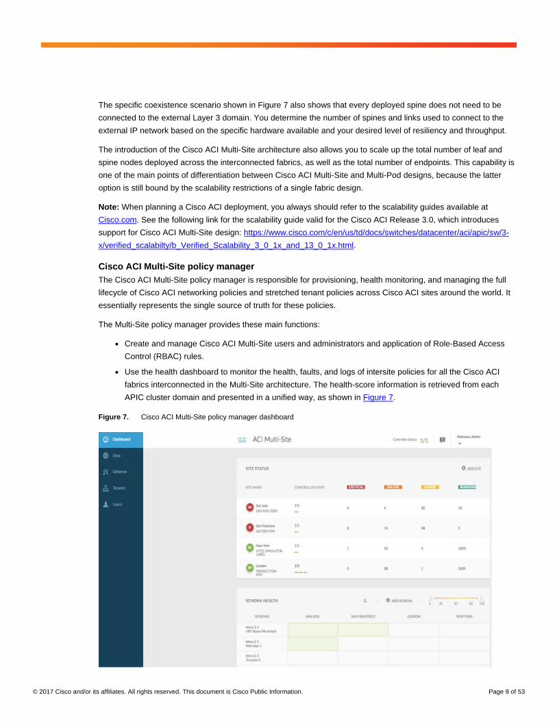
● Use the health dashboard to monitor the health, faults, and logs of intersite policies for all the Cisco ACI
fabrics interconnected in the Multi-Site architecture. The health-score information is retrieved from each
APIC cluster domain and presented in a unified way, as shown in Figure 7.
Figure 7. Cisco ACI Multi-Site policy manager dashboard
© 2017 Cisco and/or its affiliates. All rights reserved. This document is Cisco Public Information. Page 10 of 53
● Add, delete, and modify Cisco ACI sites.
● Create intersite tenants.
● Provision day-0 infrastructure to allow the spine switches at all Cisco ACI sites to peer and connect with
each other. This feature allows the system to establish MP-BGP EVPN control-plane reachability and
exchange endpoint host information (MAC and IPv4/IPv6 addresses).
● Create intersite tenant policy profiles and deploy them across sites. This feature is one of the most
important that the Multi-Site policy manager offers, together with the capability to define and provision
scoped policies for change management. When you define intersite policies, the policy manager also
properly programs the required name-space translation rules on the Multi-Site-capable spine switches
across sites.
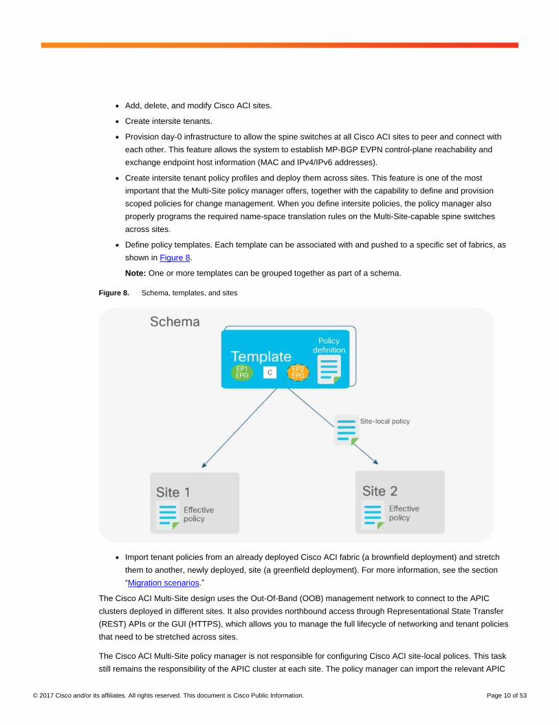
● Define policy templates. Each template can be associated with and pushed to a specific set of fabrics, as
shown in Figure 8.
Note: One or more templates can be grouped together as part of a schema.
Figure 8. Schema, templates, and sites
● Import tenant policies from an already deployed Cisco ACI fabric (a brownfield deployment) and stretch
them to another, newly deployed, site (a greenfield deployment). For more information, see the section
“Migration scenarios.”
The Cisco ACI Multi-Site design uses the Out-Of-Band (OOB) management network to connect to the APIC
clusters deployed in different sites. It also provides northbound access through Representational State Transfer
(REST) APIs or the GUI (HTTPS), which allows you to manage the full lifecycle of networking and tenant policies
that need to be stretched across sites.
The Cisco ACI Multi-Site policy manager is not responsible for configuring Cisco ACI site-local polices. This task
still remains the responsibility of the APIC cluster at each site. The policy manager can import the relevant APIC
© 2017 Cisco and/or its affiliates. All rights reserved. This document is Cisco Public Information. Page 11 of 53
cluster site-local policies and associate them with stretched objects. For example, it can import site-locally defined
VMM domains and associate them with stretched EPGs.
The Cisco ACI Multi-Site design is based on a microservices architecture in which three virtual machines are
clustered together in an active-active fashion. Internally, each virtual machine has a Docker daemon installed with
Multi-Site application services. Those services are managed and orchestrated by a Docker swarm that load-
balances all job transactions across all Multi-Site containers in concurrent active-active fashion for high availability.
A stable data-plane connection must exist between the Cisco ACI Multi-Site cluster virtual machines when they are
deployed over a WAN. The virtual machines in a Cisco ACI Multi-Site cluster communicate with each other over a
TCP connection, so if any drops occur in the WAN, dropped packets will be retransmitted. Also, be sure to
appropriately mark the Differentiated Services Code Point (DSCP) value of virtual machine traffic in a VMware port
group. The recommended approach is to mark the DSCP as Expedited Forwarding (EF).
The recommended connection bandwidth between virtual machines in a Cisco ACI Multi-Site cluster is from 300
Mbps to 1 Gbps. These numbers are based on internal stress testing while adding very large configurations and
deleting them at high frequency. In these tests, bursts of traffic of up to 250 Mbps were observed during high-scale
configurations, and bursts of up to 500 Mbps were observed during deletion of a configuration consisting of 10,000
EPGs (that is, beyond the supported scale of 800 EPGs for Cisco ACI Multi-Site deployments in Cisco ACI
Release 3.0).
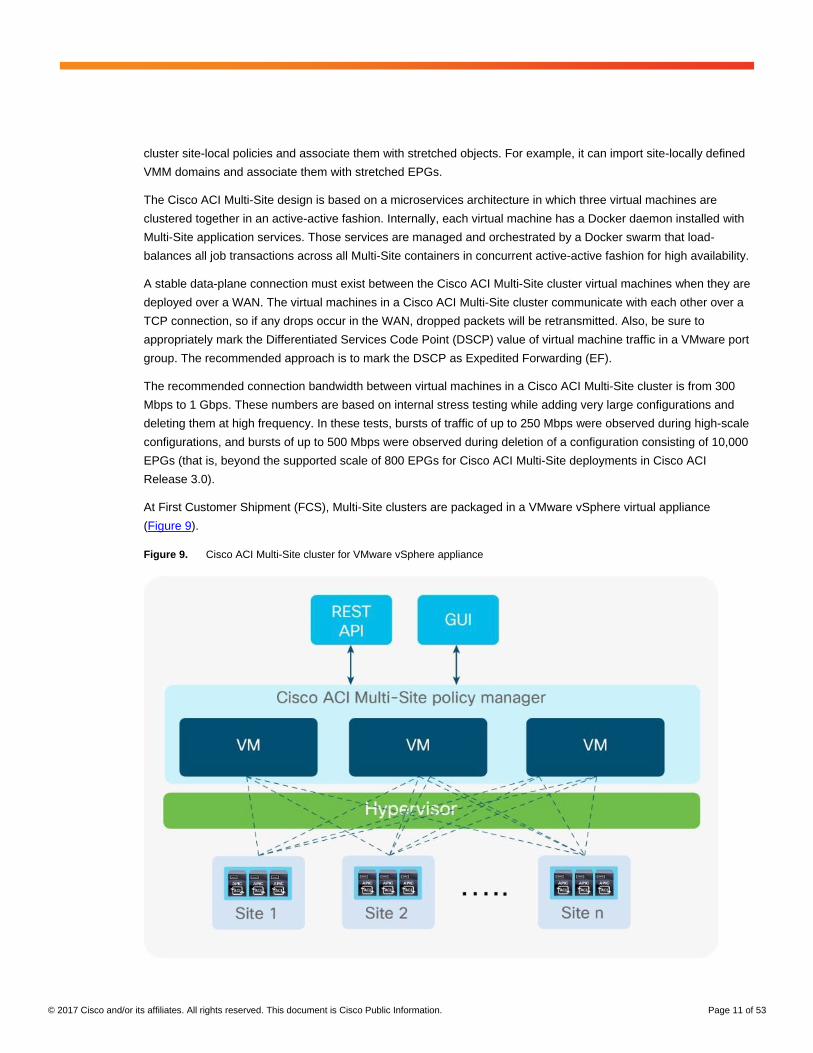
At First Customer Shipment (FCS), Multi-Site clusters are packaged in a VMware vSphere virtual appliance
(Figure 9).
Figure 9. Cisco ACI Multi-Site cluster for VMware vSphere appliance
© 2017 Cisco and/or its affiliates. All rights reserved. This document is Cisco Public Information. Page 12 of 53
For high availability, you should deploy each Multi-Site virtual machine on its own VMware ESXi host so that all
three virtual machines form a cluster over three different ESXi hosts to eliminate any single point of failure. The
overall number of VMs used for the MSC cluster has in fact a direct impact on the fault tolerance of the cluster
itself, as discussed in the document at the link below: https://docs.docker.com/engine/swarm/admin_guide/#add-
manager-nodes-for-fault-tolerance.
In the configuration with three VMs supported in ACI release 3.0, it is possible to lose one VM and have the cluster
still fully functional. The cluster would instead become inactive if losing two VMs, which leads to the
recommendation of deploying each VM on a separate ESXi host.
Note: Other form factors, such as a physical appliance and Linux Kernel-based Virtual Machine (KVM) virtual
appliance, will likely be supported in future Cisco ACI software releases.
The VMware vSphere virtual appliance requirements for each virtual machine at FCS are as follows:
● VMware ESXi 5.5 or later
● Minimum of four virtual CPUs (vCPUs), 8 Gbps of memory, and 50 GB of disk space
The supported Round-Trip Time (RTT) latency between Multi-Site virtual machines in the cluster is up to 150
milliseconds (ms), which means that the virtual machines can be deployed 150 ms apart if required. The Multi-Site
cluster communicates with each site’s APIC cluster over a secure TCP connection, and all API calls are
asynchronous. Hence, at FCS the maximum supported RTT distance is up to 1 second between the Multi-Site
cluster and each specific site’s APIC cluster. Those values may be increased in future Cisco ACI Multi-Site
software releases.
Security hardening is built in to the Cisco ACI Multi-Site cluster appliance. Note that the Cisco ACI Multi-Site cluster
design has passed all leading industry benchmark vulnerability tests such as Nessus, WhiteHat, Corona, and
Norad, resulting in no security vulnerabilities discovered in the first test run. In addition, the Multi-Site cluster design
implements IP table firewall rules in each virtual machine and opens required ports only for cluster communication.
Finally, all traffic between virtual machines in a cluster is automatically encrypted using IP Security (IPsec). Hence,
Multi-Site clusters can be deployed securely over a 150-ms RTT distance.
Cisco ACI Multi-Site deployment considerations
There are two popular use cases for Cisco ACI Multi-Site deployments:
● Centralized (local) data center, which requires the creation of separate availability zones
● Geographically distributed data centers across cities, countries, or continents, in which each data center is
an availability zone and requires a single pane for provisioning, monitoring, and management to deploy
stretched policies across availability zones
Cisco ACI Multi-Site deployment in local data center for high leaf-node scale
The centralized deployment use case is popular in the financial and government sectors. In these scenarios, a
Cisco ACI Multi-Site design is deployed in a building or a local campus with an ultra-high port count for bare-metal
server, virtual machine, or container connectivity. A high number of leaf nodes are deployed across separate Cisco
ACI fabrics to scale out the deployment and yet limit the scope of the failure domain and manage everything
though a single pane.
© 2017 Cisco and/or its affiliates. All rights reserved. This document is Cisco Public Information. Page 13 of 53
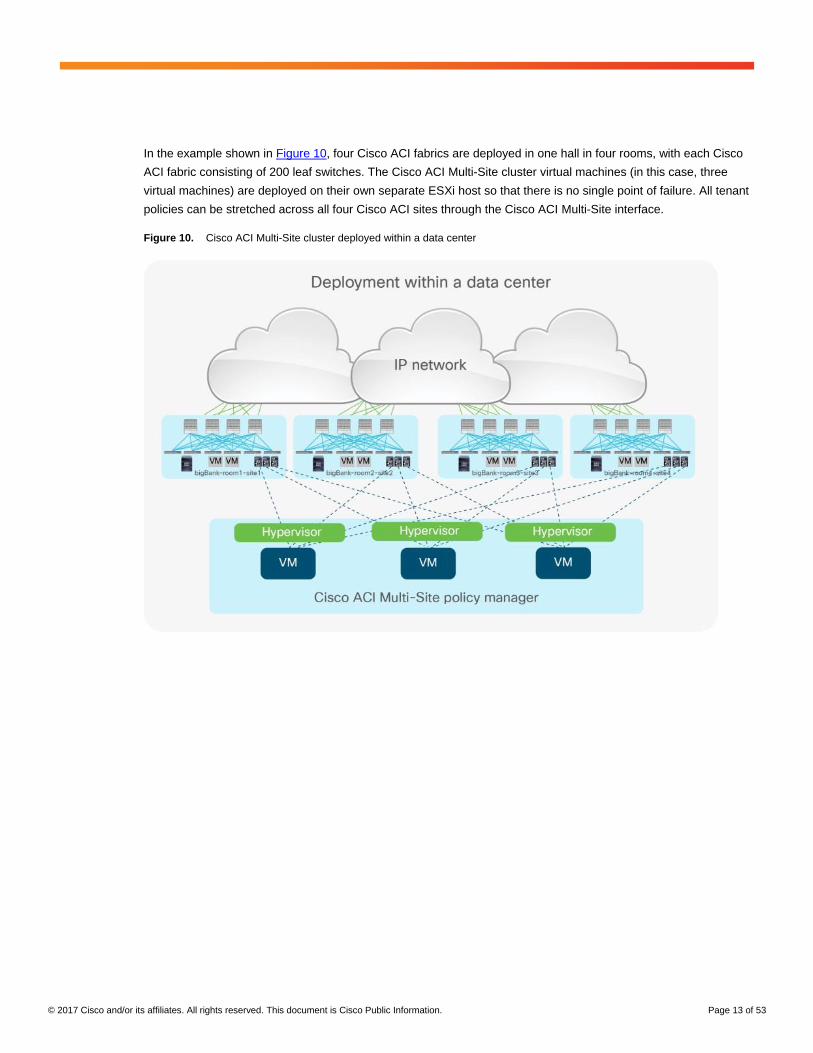
In the example shown in Figure 10, four Cisco ACI fabrics are deployed in one hall in four rooms, with each Cisco
ACI fabric consisting of 200 leaf switches. The Cisco ACI Multi-Site cluster virtual machines (in this case, three
virtual machines) are deployed on their own separate ESXi host so that there is no single point of failure. All tenant
policies can be stretched across all four Cisco ACI sites through the Cisco ACI Multi-Site interface.
Figure 10. Cisco ACI Multi-Site cluster deployed within a data center
© 2017 Cisco and/or its affiliates. All rights reserved. This document is Cisco Public Information. Page 14 of 53
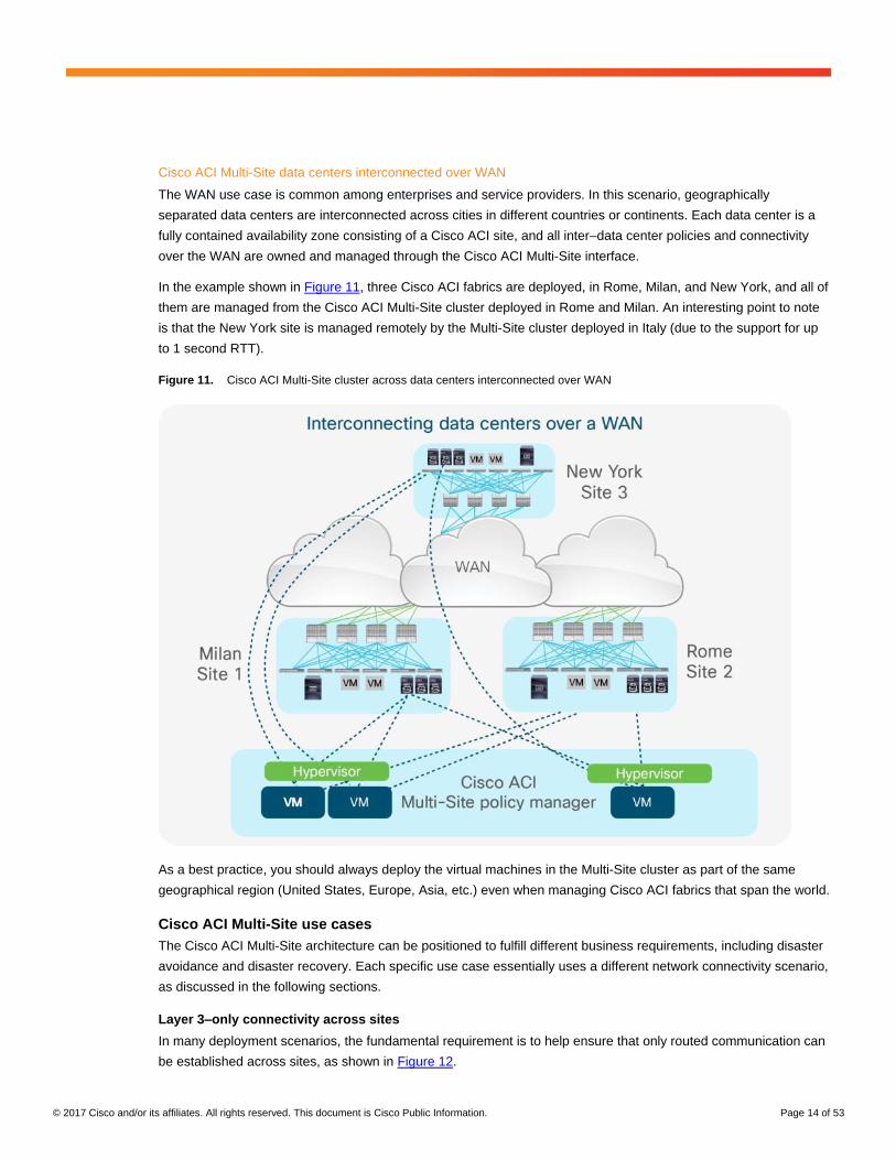
Cisco ACI Multi-Site data centers interconnected over WAN
The WAN use case is common among enterprises and service providers. In this scenario, geographically
separated data centers are interconnected across cities in different countries or continents. Each data center is a
fully contained availability zone consisting of a Cisco ACI site, and all inter–data center policies and connectivity
over the WAN are owned and managed through the Cisco ACI Multi-Site interface.
In the example shown in Figure 11, three Cisco ACI fabrics are deployed, in Rome, Milan, and New York, and all of
them are managed from the Cisco ACI Multi-Site cluster deployed in Rome and Milan. An interesting point to note
is that the New York site is managed remotely by the Multi-Site cluster deployed in Italy (due to the support for up
to 1 second RTT).
Figure 11. Cisco ACI Multi-Site cluster across data centers interconnected over WAN
As a best practice, you should always deploy the virtual machines in the Multi-Site cluster as part of the same
geographical region (United States, Europe, Asia, etc.) even when managing Cisco ACI fabrics that span the world.
Cisco ACI Multi-Site use cases
The Cisco ACI Multi-Site architecture can be positioned to fulfill different business requirements, including disaster
avoidance and disaster recovery. Each specific use case essentially uses a different network connectivity scenario,
as discussed in the following sections.
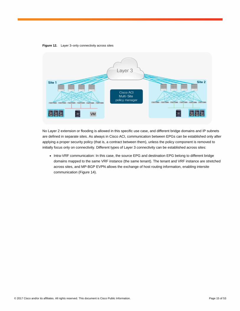
Layer 3–only connectivity across sites
In many deployment scenarios, the fundamental requirement is to help ensure that only routed communication can
be established across sites, as shown in Figure 12.
© 2017 Cisco and/or its affiliates. All rights reserved. This document is Cisco Public Information. Page 15 of 53
Figure 12. Layer 3–only connectivity across sites
No Layer 2 extension or flooding is allowed in this specific use case, and different bridge domains and IP subnets
are defined in separate sites. As always in Cisco ACI, communication between EPGs can be established only after
applying a proper security policy (that is, a contract between them), unless the policy component is removed to
initially focus only on connectivity. Different types of Layer 3 connectivity can be established across sites:
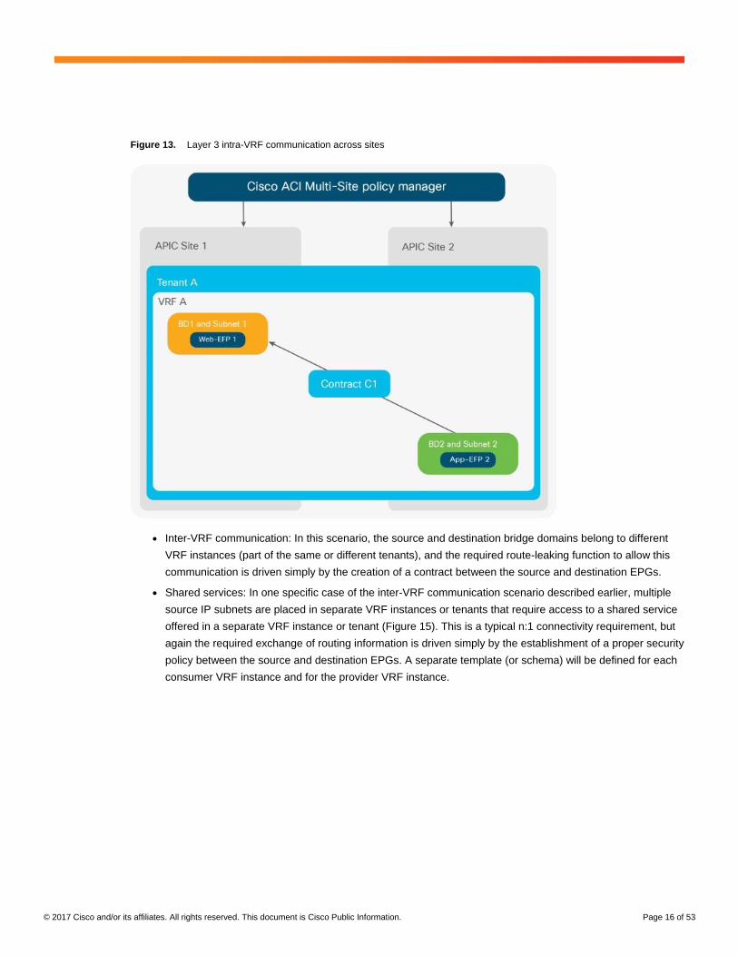
● Intra-VRF communication: In this case, the source EPG and destination EPG belong to different bridge
domains mapped to the same VRF instance (the same tenant). The tenant and VRF instance are stretched
across sites, and MP-BGP EVPN allows the exchange of host routing information, enabling intersite
communication (Figure 14).
© 2017 Cisco and/or its affiliates. All rights reserved. This document is Cisco Public Information. Page 16 of 53
Figure 13. Layer 3 intra-VRF communication across sites
● Inter-VRF communication: In this scenario, the source and destination bridge domains belong to different
VRF instances (part of the same or different tenants), and the required route-leaking function to allow this
communication is driven simply by the creation of a contract between the source and destination EPGs.
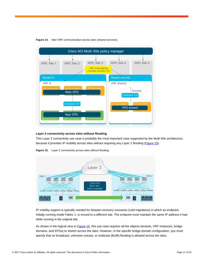
● Shared services: In one specific case of the inter-VRF communication scenario described earlier, multiple
source IP subnets are placed in separate VRF instances or tenants that require access to a shared service
offered in a separate VRF instance or tenant (Figure 15). This is a typical n:1 connectivity requirement, but
again the required exchange of routing information is driven simply by the establishment of a proper security
policy between the source and destination EPGs. A separate template (or schema) will be defined for each
consumer VRF instance and for the provider VRF instance.
© 2017 Cisco and/or its affiliates. All rights reserved. This document is Cisco Public Information. Page 17 of 53
Figure 14. Inter-VRF communication across sites (shared services)
Layer 2 connectivity across sites without flooding
This Layer 2 connectivity use case is probably the most important case supported by the Multi-Site architecture,
because it provides IP mobility across sites without requiring any Layer 2 flooding (Figure 15).
Figure 15. Layer 2 connectivity across sites without flooding
IP mobility support is typically needed for disaster-recovery scenarios (cold migrations) in which an endpoint,
initially running inside Fabric 1, is moved to a different site. The endpoint must maintain the same IP address it had
while running in the original site.
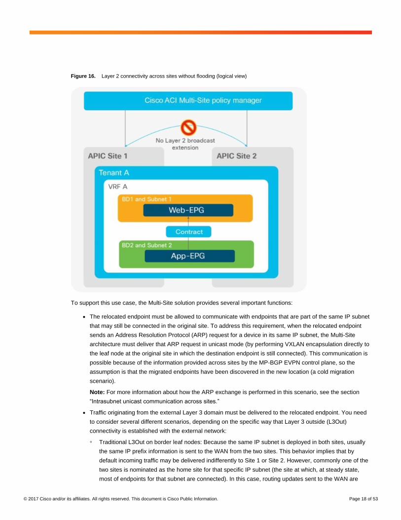
As shown in the logical view in Figure 16, this use case requires all the objects (tenants, VRF instances, bridge
domains, and EPGs) to stretch across the sites. However, in the specific bridge domain configuration, you must
specify that no broadcast, unknown unicast, or multicast (BUM) flooding is allowed across the sites.
© 2017 Cisco and/or its affiliates. All rights reserved. This document is Cisco Public Information. Page 18 of 53
Figure 16. Layer 2 connectivity across sites without flooding (logical view)
To support this use case, the Multi-Site solution provides several important functions:
● The relocated endpoint must be allowed to communicate with endpoints that are part of the same IP subnet
that may still be connected in the original site. To address this requirement, when the relocated endpoint
sends an Address Resolution Protocol (ARP) request for a device in its same IP subnet, the Multi-Site
architecture must deliver that ARP request in unicast mode (by performing VXLAN encapsulation directly to
the leaf node at the original site in which the destination endpoint is still connected). This communication is
possible because of the information provided across sites by the MP-BGP EVPN control plane, so the
assumption is that the migrated endpoints have been discovered in the new location (a cold migration
scenario).
Note: For more information about how the ARP exchange is performed in this scenario, see the section
“Intrasubnet unicast communication across sites.”
● Traffic originating from the external Layer 3 domain must be delivered to the relocated endpoint. You need
to consider several different scenarios, depending on the specific way that Layer 3 outside (L3Out)
connectivity is established with the external network:
◦ Traditional L3Out on border leaf nodes: Because the same IP subnet is deployed in both sites, usually
the same IP prefix information is sent to the WAN from the two sites. This behavior implies that by
default incoming traffic may be delivered indifferently to Site 1 or Site 2. However, commonly one of the
two sites is nominated as the home site for that specific IP subnet (the site at which, at steady state,
most of endpoints for that subnet are connected). In this case, routing updates sent to the WAN are
© 2017 Cisco and/or its affiliates. All rights reserved. This document is Cisco Public Information. Page 19 of 53
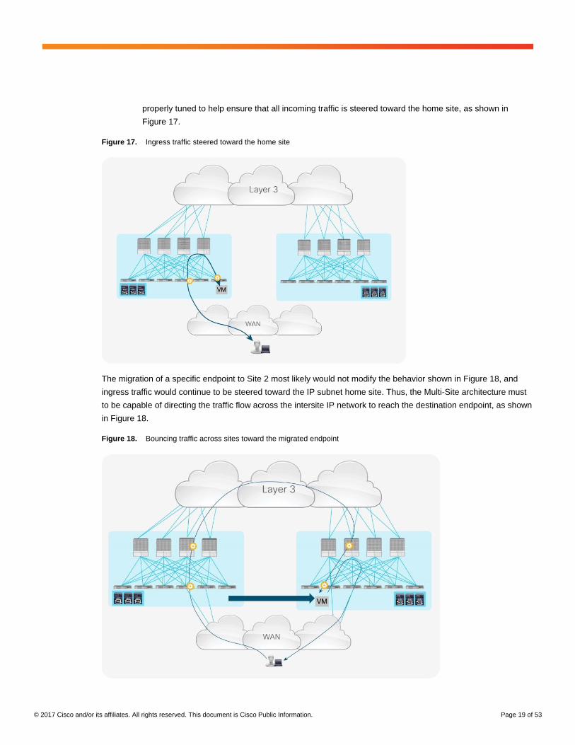
properly tuned to help ensure that all incoming traffic is steered toward the home site, as shown in
Figure 17.
Figure 17. Ingress traffic steered toward the home site
The migration of a specific endpoint to Site 2 most likely would not modify the behavior shown in Figure 18, and
ingress traffic would continue to be steered toward the IP subnet home site. Thus, the Multi-Site architecture must
to be capable of directing the traffic flow across the intersite IP network to reach the destination endpoint, as shown
in Figure 18.
Figure 18. Bouncing traffic across sites toward the migrated endpoint
© 2017 Cisco and/or its affiliates. All rights reserved. This document is Cisco Public Information. Page 20 of 53
Again, this behavior is possible because of the dynamic discovery in Site 2 of the migrated endpoint,
which triggers an EVPN update from the spine nodes in Site 2 to the spine nodes in Site 1. This update
essentially provides Site 1 with the location information for the recovered endpoint required to redirect
the traffic flows as shown in Figure 19.
Note that after the migration, the return traffic from the migrated endpoint toward the remote client starts
using the local L3Out connection in Fabric 2, leading to the creation of an asymmetric traffic path. This
behavior may lead to the drop of traffic in designs in which independent stateful firewalls are deployed
between the fabrics and the WAN. The use of EVPN-based L3Out connections, often referred to as
GOLF can be positioned to avoid this problem.
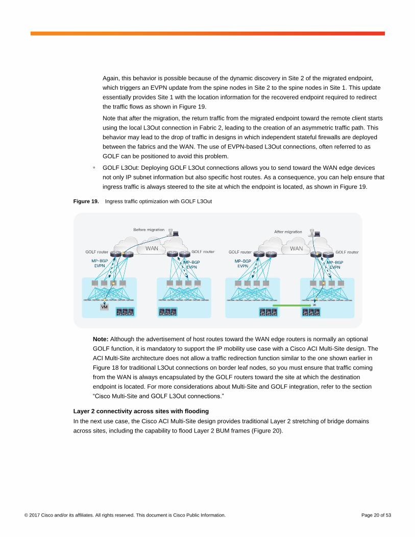
◦ GOLF L3Out: Deploying GOLF L3Out connections allows you to send toward the WAN edge devices
not only IP subnet information but also specific host routes. As a consequence, you can help ensure that
ingress traffic is always steered to the site at which the endpoint is located, as shown in Figure 19.
Figure 19. Ingress traffic optimization with GOLF L3Out
Note: Although the advertisement of host routes toward the WAN edge routers is normally an optional
GOLF function, it is mandatory to support the IP mobility use case with a Cisco ACI Multi-Site design. The
ACI Multi-Site architecture does not allow a traffic redirection function similar to the one shown earlier in
Figure 18 for traditional L3Out connections on border leaf nodes, so you must ensure that traffic coming
from the WAN is always encapsulated by the GOLF routers toward the site at which the destination
endpoint is located. For more considerations about Multi-Site and GOLF integration, refer to the section
“Cisco Multi-Site and GOLF L3Out connections.”
Layer 2 connectivity across sites with flooding
In the next use case, the Cisco ACI Multi-Site design provides traditional Layer 2 stretching of bridge domains
across sites, including the capability to flood Layer 2 BUM frames (Figure 20).
© 2017 Cisco and/or its affiliates. All rights reserved. This document is Cisco Public Information. Page 21 of 53
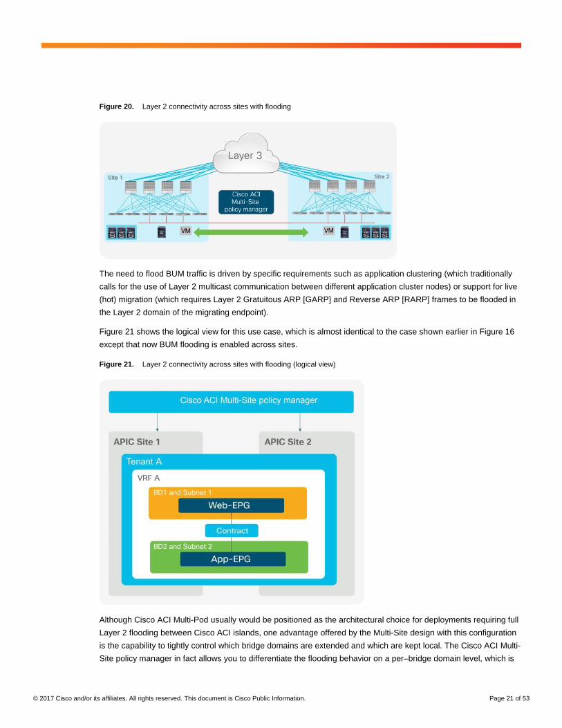
Figure 20. Layer 2 connectivity across sites with flooding
The need to flood BUM traffic is driven by specific requirements such as application clustering (which traditionally
calls for the use of Layer 2 multicast communication between different application cluster nodes) or support for live
(hot) migration (which requires Layer 2 Gratuitous ARP [GARP] and Reverse ARP [RARP] frames to be flooded in
the Layer 2 domain of the migrating endpoint).
Figure 21 shows the logical view for this use case, which is almost identical to the case shown earlier in Figure 16
except that now BUM flooding is enabled across sites.
Figure 21. Layer 2 connectivity across sites with flooding (logical view)
Although Cisco ACI Multi-Pod usually would be positioned as the architectural choice for deployments requiring full
Layer 2 flooding between Cisco ACI islands, one advantage offered by the Multi-Site design with this configuration
is the capability to tightly control which bridge domains are extended and which are kept local. The Cisco ACI Multi-
Site policy manager in fact allows you to differentiate the flooding behavior on a per–bridge domain level, which is
© 2017 Cisco and/or its affiliates. All rights reserved. This document is Cisco Public Information. Page 22 of 53
useful in a real-life scenario in which the flooding behavior must be supported only in a subset of the stretched
bridge domains.
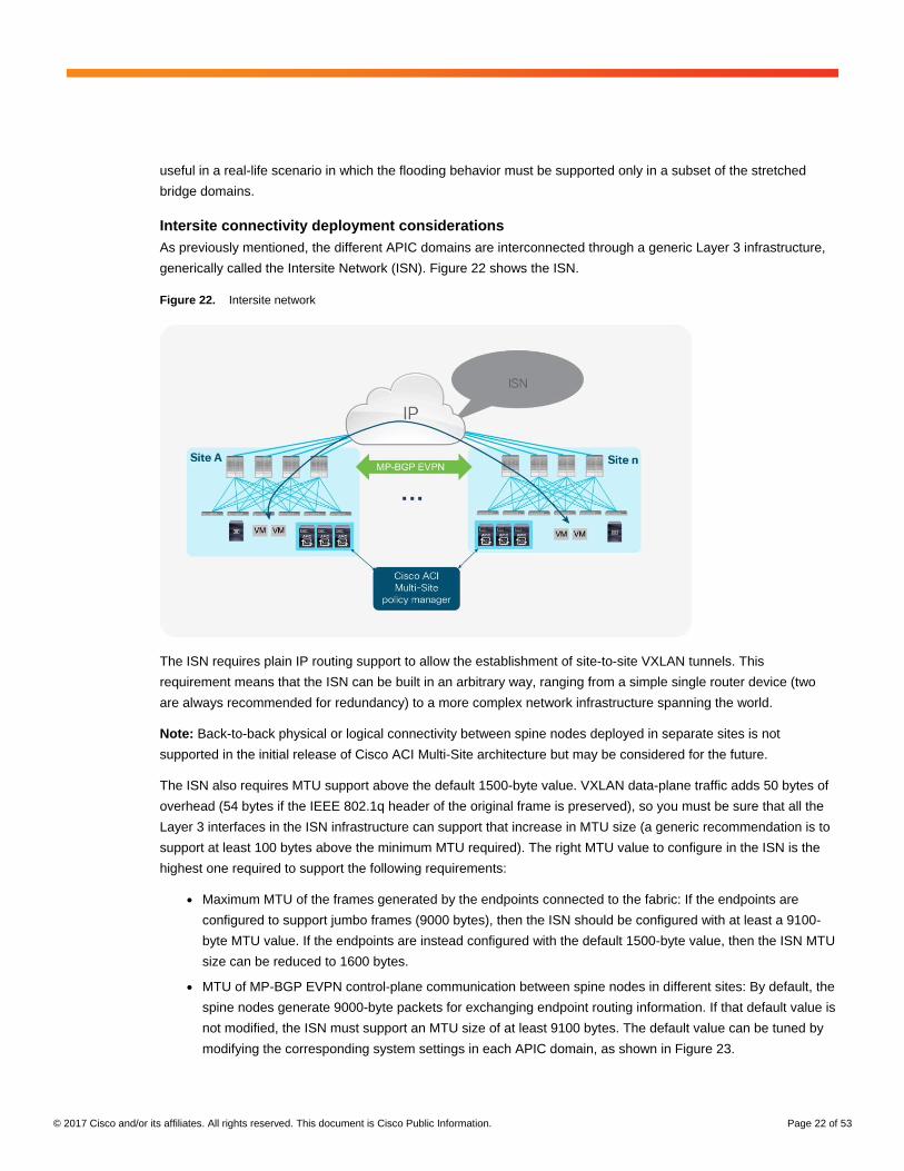
Intersite connectivity deployment considerations
As previously mentioned, the different APIC domains are interconnected through a generic Layer 3 infrastructure,
generically called the Intersite Network (ISN). Figure 22 shows the ISN.
Figure 22. Intersite network
The ISN requires plain IP routing support to allow the establishment of site-to-site VXLAN tunnels. This
requirement means that the ISN can be built in an arbitrary way, ranging from a simple single router device (two
are always recommended for redundancy) to a more complex network infrastructure spanning the world.
Note: Back-to-back physical or logical connectivity between spine nodes deployed in separate sites is not
supported in the initial release of Cisco ACI Multi-Site architecture but may be considered for the future.
The ISN also requires MTU support above the default 1500-byte value. VXLAN data-plane traffic adds 50 bytes of
overhead (54 bytes if the IEEE 802.1q header of the original frame is preserved), so you must be sure that all the
Layer 3 interfaces in the ISN infrastructure can support that increase in MTU size (a generic recommendation is to
support at least 100 bytes above the minimum MTU required). The right MTU value to configure in the ISN is the
highest one required to support the following requirements:
● Maximum MTU of the frames generated by the endpoints connected to the fabric: If the endpoints are
configured to support jumbo frames (9000 bytes), then the ISN should be configured with at least a 9100-
byte MTU value. If the endpoints are instead configured with the default 1500-byte value, then the ISN MTU
size can be reduced to 1600 bytes.
● MTU of MP-BGP EVPN control-plane communication between spine nodes in different sites: By default, the
spine nodes generate 9000-byte packets for exchanging endpoint routing information. If that default value is
not modified, the ISN must support an MTU size of at least 9100 bytes. The default value can be tuned by
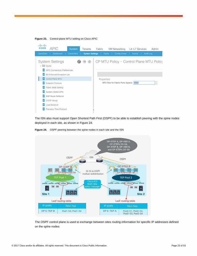
modifying the corresponding system settings in each APIC domain, as shown in Figure 23.
© 2017 Cisco and/or its affiliates. All rights reserved. This document is Cisco Public Information. Page 23 of 53
Figure 23. Control-plane MTU setting on Cisco APIC
The ISN also must support Open Shortest Path First (OSPF) to be able to establish peering with the spine nodes
deployed in each site, as shown in Figure 24.
Figure 24. OSPF peering between the spine nodes in each site and the ISN
The OSPF control plane is used to exchange between sites routing information for specific IP addresses defined
on the spine nodes:
© 2017 Cisco and/or its affiliates. All rights reserved. This document is Cisco Public Information. Page 24 of 53
● Control-Plane External Tunnel Endpoint (CP-ETEP): This unique IP address is defined on each spine node
belonging to a fabric and is used to establish MP-BGP EVPN adjacencies with the spine nodes in remote
pods.
Note: The “E” refers to the fact that the IP addresses must not be part of the TEP pool defined at a given
site and should instead be “external” and, if needed, globally routable (because different sites may be
interconnected by public Layer 3 networks).
● Data-Plane ETEP (DP-ETEP): This common anycast address is shared by all the spine nodes at the same
site and is used to source and receive unicast VXLAN data-plane traffic. Each site is characterized by a DP-
ETEP address that essentially uniquely identifies the site.
● Head-End Replication ETEP (HER-ETEP): This common anycast address is shared by all the spine nodes
in the same site and is used to perform head-end replication for BUM traffic. BUM traffic is sourced from the
HER-DTEP address defined on the local spine nodes and destined for the HER-DTEP of remote sites to
which the given bridge domain is being stretched.
As shown in Figure 25, the CP-ETEP, DP-ETEP, and HER-ETEP addresses are the only prefixes that must be
exchanged across sites to enable the intersite EVPN control plane and the VXLAN data plane. As a consequence,
they are also the only prefixes that are learned in the ISN routing domain.
Note: The TEP pool prefixes used within each site do not need to be exchanged across sites to allow intersite
communication. As a consequence, there are no technical restrictions regarding how those pools should be
assigned. However, the strong recommendation is not to assign overlapping TEP pools across separate sites so
that your system is prepared for future functions that may require the exchange of TEP pool summary prefixes.
Note that multicast support is not required within the ISN to allow the exchange of Layer 2 multidestination (BUM)
traffic across pods in the specific use case in which a bridge domain is stretched with flooding enabled. This
support is not required because the Cisco ACI Multi-Site design uses the HER function on the spine nodes of the
source site to replicate BUM traffic to all the remote sites on which that bridge domain is stretched. For more
information about this capability, refer to the section “Layer 2 BUM traffic handling across sites.”
Multi-Site overlay control plane
In a Cisco ACI fabric, information about all the endpoints connected to the leaf nodes is stored in the COOP
database available in the spine nodes. Every time an endpoint is discovered as locally connected to a given leaf
node, the leaf node originates a COOP control-plane message to communicate the endpoint information (IPv4/IPv6
and MAC addresses) to the spine nodes. COOP is also used by the spines to synchronize this information between
them.
In a Cisco ACI Multi-Site deployment, host information for discovered endpoints must be exchanged between spine
nodes that are part of separate fabrics to allow east-west communication between endpoints. This intersite
exchange of host information is required only for the endpoints that really need to communicate, and it is controlled
by the establishment of intersite policies between EPGs. This behavior is important because it allows you to
increase the overall number of endpoints that can be supported across sites, because only information for a subset
of those endpoints is synchronized across sites.
Note: You can control the exchange of endpoint information at the bridge domain level. Therefore, if multiple EPGs
are part of the same bridge domain and a specific policy dictates the exchange of routes for one of those EPGs,
endpoint information also will be sent for all the other EPGs.
© 2017 Cisco and/or its affiliates. All rights reserved. This document is Cisco Public Information. Page 25 of 53
Figure 25 shows in detail the sequence of overlay control-plane events.
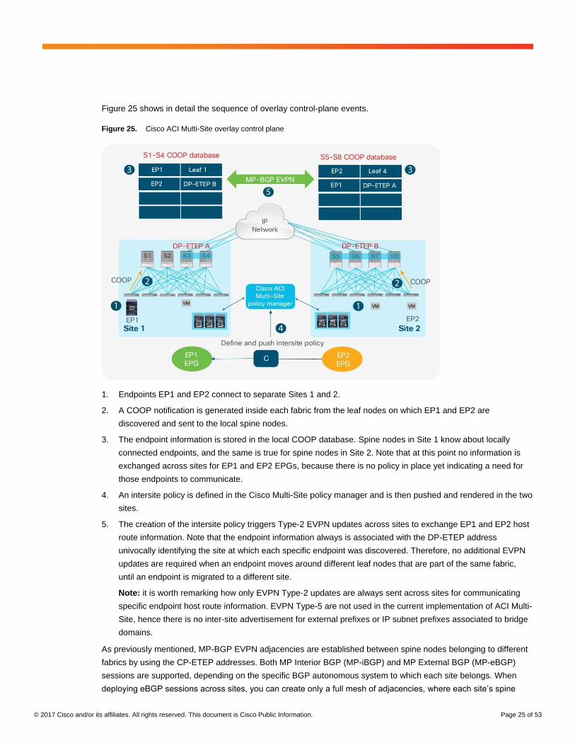
Figure 25. Cisco ACI Multi-Site overlay control plane
1. Endpoints EP1 and EP2 connect to separate Sites 1 and 2.
2. A COOP notification is generated inside each fabric from the leaf nodes on which EP1 and EP2 are
discovered and sent to the local spine nodes.
3. The endpoint information is stored in the local COOP database. Spine nodes in Site 1 know about locally
connected endpoints, and the same is true for spine nodes in Site 2. Note that at this point no information is
exchanged across sites for EP1 and EP2 EPGs, because there is no policy in place yet indicating a need for
those endpoints to communicate.
4. An intersite policy is defined in the Cisco Multi-Site policy manager and is then pushed and rendered in the two
sites.
5. The creation of the intersite policy triggers Type-2 EVPN updates across sites to exchange EP1 and EP2 host
route information. Note that the endpoint information always is associated with the DP-ETEP address
univocally identifying the site at which each specific endpoint was discovered. Therefore, no additional EVPN
updates are required when an endpoint moves around different leaf nodes that are part of the same fabric,
until an endpoint is migrated to a different site.
Note: it is worth remarking how only EVPN Type-2 updates are always sent across sites for communicating
specific endpoint host route information. EVPN Type-5 are not used in the current implementation of ACI Multi-
Site, hence there is no inter-site advertisement for external prefixes or IP subnet prefixes associated to bridge
domains.
As previously mentioned, MP-BGP EVPN adjacencies are established between spine nodes belonging to different
fabrics by using the CP-ETEP addresses. Both MP Interior BGP (MP-iBGP) and MP External BGP (MP-eBGP)
sessions are supported, depending on the specific BGP autonomous system to which each site belongs. When
deploying eBGP sessions across sites, you can create only a full mesh of adjacencies, where each site’s spine
© 2017 Cisco and/or its affiliates. All rights reserved. This document is Cisco Public Information. Page 26 of 53
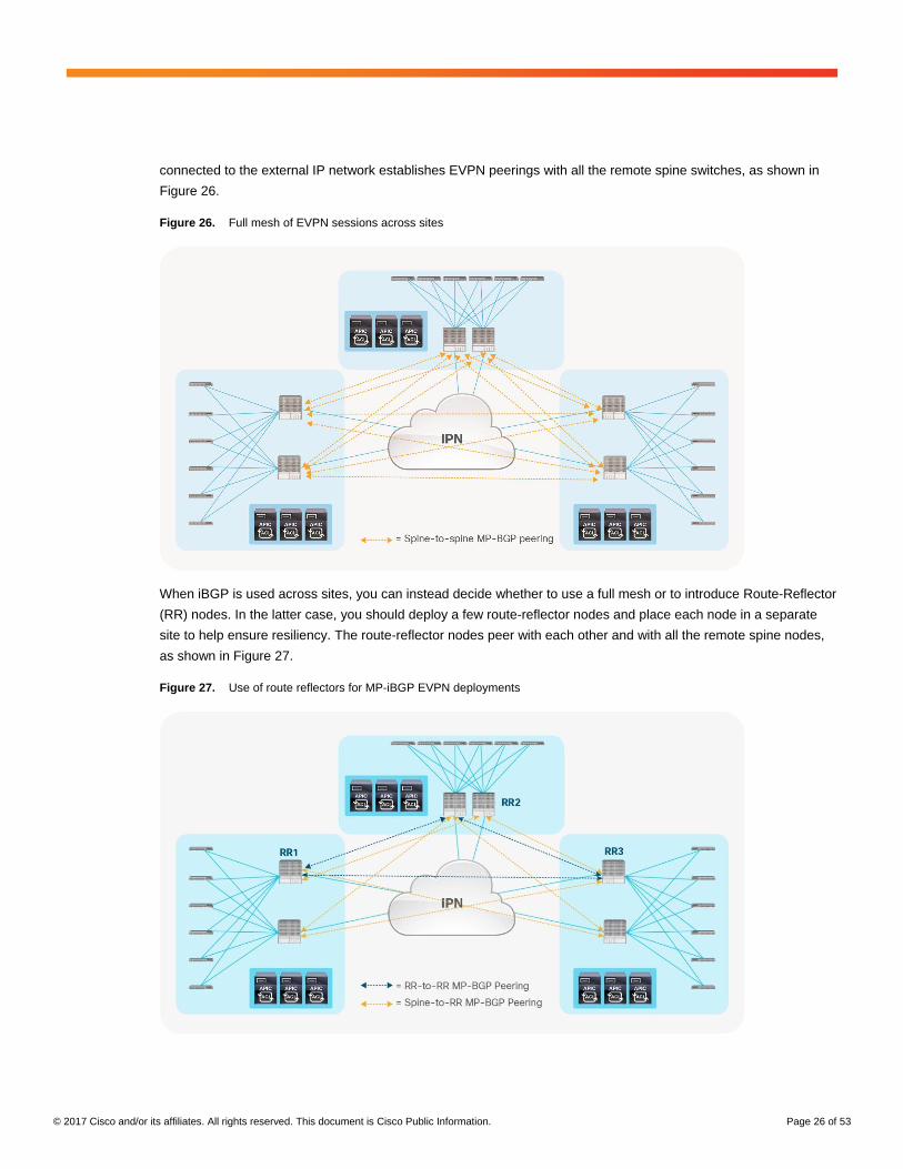
connected to the external IP network establishes EVPN peerings with all the remote spine switches, as shown in
Figure 26.
Figure 26. Full mesh of EVPN sessions across sites
When iBGP is used across sites, you can instead decide whether to use a full mesh or to introduce Route-Reflector
(RR) nodes. In the latter case, you should deploy a few route-reflector nodes and place each node in a separate
site to help ensure resiliency. The route-reflector nodes peer with each other and with all the remote spine nodes,
as shown in Figure 27.
Figure 27. Use of route reflectors for MP-iBGP EVPN deployments
© 2017 Cisco and/or its affiliates. All rights reserved. This document is Cisco Public Information. Page 27 of 53
Notice how there is no local MP-BGP peering established between the spines deployed in the same site. As a
consequence, it is imperative to deploy one RR in at least there separate sites, to ensure that the spines deployed
in a site with a RR will maintain established MP-BGP sessions even in the failure scenario of one remote RR node.
The best practice recommendation is to keep the default behavior of using full-mesh peering for both the eBGP
and iBGP deployments, given the fact that the expectation is that a limited (i.e. less than 20) number of sites will
likely always be interconnected and this does not pose any scalability concern.
Note: 5 sites are supported in the initial ACI release 3.0.
A hybrid scenario also is supported. In this scenario, some sites are deployed as part of the same BGP
autonomous system (and hence can peer full mesh or make use of a route reflector), and other sites are part of
different BGP autonomous system.
Multi-Site overlay data plane
After endpoint information is exchanged across sites, the VXLAN data plane is used to allow intersite Layer 2 and
Layer 3 communication. Before exploring in detail how this communication can be established, you should
understand how Layer 2 multidestination traffic (usually referred to as BUM) is handled across sites.
Layer 2 BUM traffic handling across sites
The deployment of VXLAN allows the use of a logical abstraction so that endpoints separated by multiple Layer 3
hops can communicate as if they were part of the same logical Layer 2 domain. Thus, those endpoints must be
capable of sourcing Layer 2 multidestination frames received by all the other endpoints connected to the same
Layer 2 segment, regardless of their actual physical location.
This capability can be achieved either by using the native multicast replication functions offered by the Layer 3
infrastructure interconnecting the endpoints (this is the approach adopted in the Cisco ACI Multi-Pod architecture)
or by enabling head-end replication functions (often referred to as HER) on the source VXLAN TEP (VTEP)
devices, which create multiple unicast copies of each BUM frame to be sent to all the remote VTEPs on which
those endpoints are connected.
The Cisco ACI Multi-Site design adopts this second approach, with the Multi-Site-capable spine switches
performing the HER function, because the interconnected fabrics may be deployed around the world and it would
be difficult to ensure proper multicast support across the entire interconnecting network infrastructure.
Note: The transmission of Layer 2 BUM frames across sites is required only for the specific bridge domains that
are stretched with flooding enabled (i.e. the “INTERSITEBUMTRAFFICALLOW” flag is configured for the bridge
domains). Also, the purpose of this section is to describe how BUM traffic is forwarded across sites when needed;
however, specific bridge domain configuration can be used to control what BUM frames are sent between sites, as
described in more detail in the “Intrasubnet unicast communication across sites“ section.
Figure 28 shows the sequence of events required to send Layer 2 BUM traffic across sites.
© 2017 Cisco and/or its affiliates. All rights reserved. This document is Cisco Public Information. Page 28 of 53
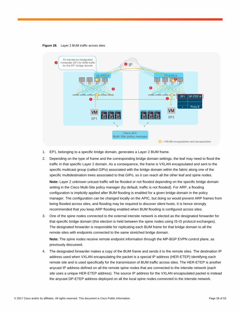
Figure 28. Layer 2 BUM traffic across sites
1. EP1, belonging to a specific bridge domain, generates a Layer 2 BUM frame.
2. Depending on the type of frame and the corresponding bridge domain settings, the leaf may need to flood the
traffic in that specific Layer 2 domain. As a consequence, the frame is VXLAN encapsulated and sent to the
specific multicast group (called GIPo) associated with the bridge domain within the fabric along one of the
specific multidestination trees associated to that GIPo, so it can reach all the other leaf and spine nodes.
Note: Layer 2 unknown unicast traffic will be flooded or not flooded depending on the specific bridge domain
setting in the Cisco Multi-Site policy manager (by default, traffic is not flooded). For ARP, a flooding
configuration is implicitly applied after BUM flooding is enabled for a given bridge domain in the policy
manager. The configuration can be changed locally on the APIC, but doing so would prevent ARP frames from
being flooded across sites, and flooding may be required to discover silent hosts. It is hence strongly
recommended that you keep ARP flooding enabled when BUM flooding is configured across sites.
3. One of the spine nodes connected to the external intersite network is elected as the designated forwarder for
that specific bridge domain (this election is held between the spine nodes using IS-IS protocol exchanges).
The designated forwarder is responsible for replicating each BUM frame for that bridge domain to all the
remote sites with endpoints connected to the same stretched bridge domain.
Note: The spine nodes receive remote endpoint information through the MP-BGP EVPN control plane, as
previously discussed.
4. The designated forwarder makes a copy of the BUM frame and sends it to the remote sites. The destination IP
address used when VXLAN encapsulating the packet is a special IP address (HER-ETEP) identifying each
remote site and is used specifically for the transmission of BUM traffic across sites. The HER-ETEP is another
anycast IP address defined on all the remote spine nodes that are connected to the intersite network (each
site uses a unique HER-ETEP address). The source IP address for the VXLAN encapsulated packet is instead
the anycast DP-ETEP address deployed on all the local spine nodes connected to the intersite network.
© 2017 Cisco and/or its affiliates. All rights reserved. This document is Cisco Public Information. Page 29 of 53
Note: The HER-ETEP (referred to as multicast data TEP in the Cisco ACI Multi-Site GUI) is yet another IP
address that must be sent to the Layer 3 network connecting the fabrics, as already shown in Figure 24.
5. One of the remote spine nodes receives the packet, translates the VNID value contained in the header to the
locally significant VNID value associated with the same bridge domain, and sends the traffic to the site along
one of the local multidestination trees defined for the bridge domain.
6. The traffic is forwarded within the site and reaches all the spine and leaf nodes with endpoints actively
connected to the specific bridge domain.
7. The receiving leaf nodes use the information contained in the VXLAN header to learn the site location for
endpoint EP1 that sourced the BUM frame. They also send the BUM frame to all the local interfaces
associated with the bridge domain, so that endpoint EP2 (in this example) can receive it.
As previously mentioned, any defined bridge domain is associated with a multicast group address (or a set of
multicast addresses), usually referred to as the GIPo address. Depending on the number of configured bridge
domains, the same GIPo address may be associated with different bridge domains. Thus, when flooding for one of
those bridge domains is enabled across sites, BUM traffic for the other bridge domains using the same GIPo
address is also sent across the sites and will then be dropped on the received spine nodes. This behavior can
increase the bandwidth utilization in the intersite network.
Because of this behavior, when a bridge domain is configured as stretched with BUM flooding enabled from the
Cisco ACI Multi-Site GUI, by default a GIPo address is assigned from a separate range of multicast addresses.
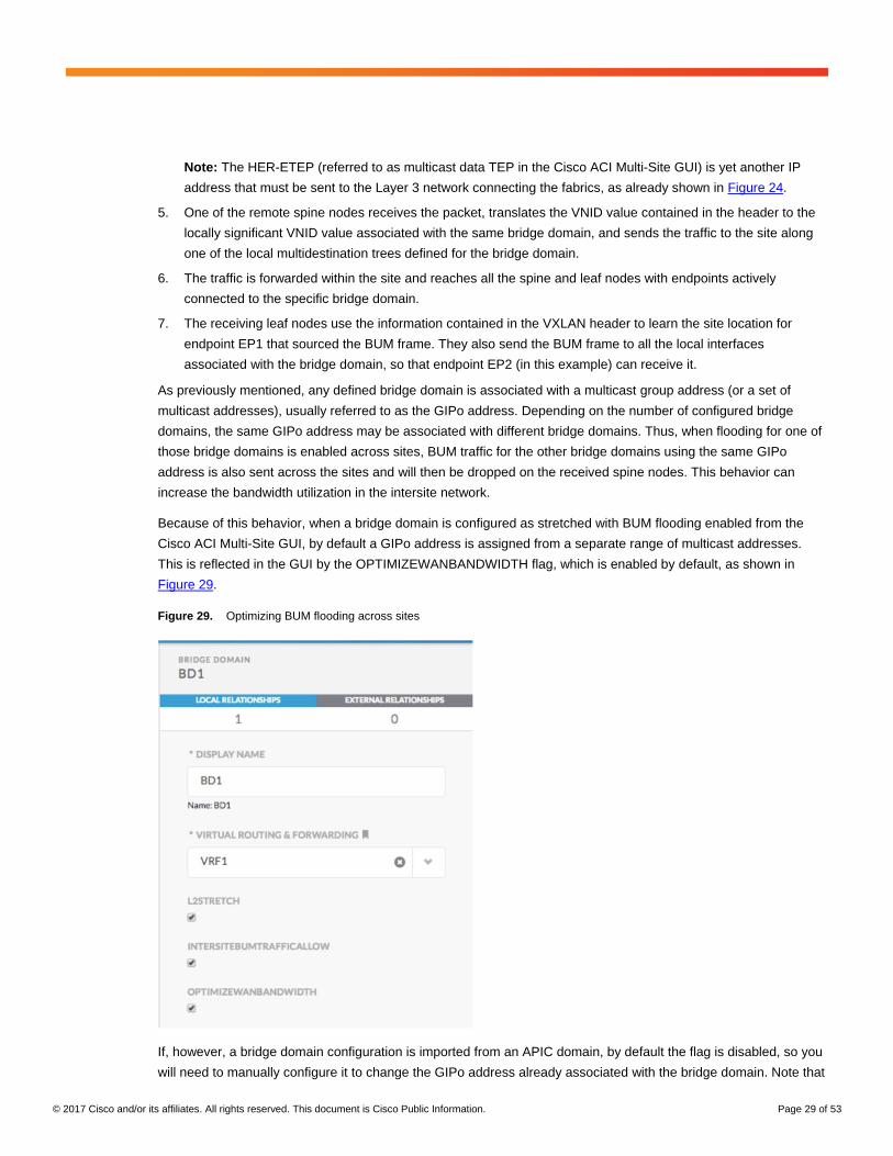
This is reflected in the GUI by the OPTIMIZEWANBANDWIDTH flag, which is enabled by default, as shown in
Figure 29.
Figure 29. Optimizing BUM flooding across sites
If, however, a bridge domain configuration is imported from an APIC domain, by default the flag is disabled, so you
will need to manually configure it to change the GIPo address already associated with the bridge domain. Note that
© 2017 Cisco and/or its affiliates. All rights reserved. This document is Cisco Public Information. Page 30 of 53
doing so will cause a few seconds of outage for the intrafabric BUM traffic for the bridge domain while the GIPo
address is updated on all the leaf nodes on which that specific bridge domain is deployed.
Intrasubnet unicast communication across sites
The first requirement before intrasubnet communication across sites can be achieved is to complete the ARP
exchange between source and destination endpoints. There are two different scenarios to consider:
● The endpoints are part of a bridge domain stretched across sites with BUM flooding enabled. In this case,
the behavior is identical to that discussed in the previous section and shown in Figure 28. The ARP request
will reach the destination endpoints in remote sites, which will allow the remote leaf nodes to learn the site
location of the source endpoint. As a consequence, the ARP unicast reply will be directly VXLAN
encapsulated to the DP-ETEP address identifying the EP1 site, and one of the receiving spine nodes will
perform the VNID and class-ID translation and send the frame toward the local leaf node to which EP1 is
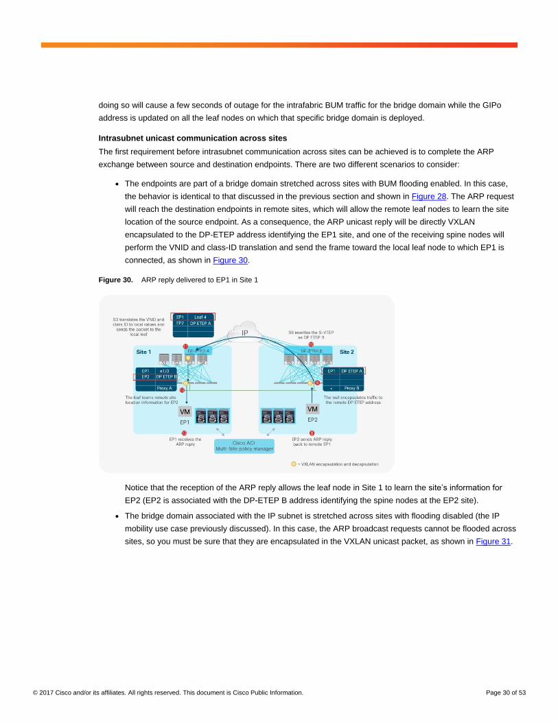
connected, as shown in Figure 30.
Figure 30. ARP reply delivered to EP1 in Site 1
Notice that the reception of the ARP reply allows the leaf node in Site 1 to learn the site’s information for
EP2 (EP2 is associated with the DP-ETEP B address identifying the spine nodes at the EP2 site).
● The bridge domain associated with the IP subnet is stretched across sites with flooding disabled (the IP
mobility use case previously discussed). In this case, the ARP broadcast requests cannot be flooded across
sites, so you must be sure that they are encapsulated in the VXLAN unicast packet, as shown in Figure 31.
© 2017 Cisco and/or its affiliates. All rights reserved. This document is Cisco Public Information. Page 31 of 53
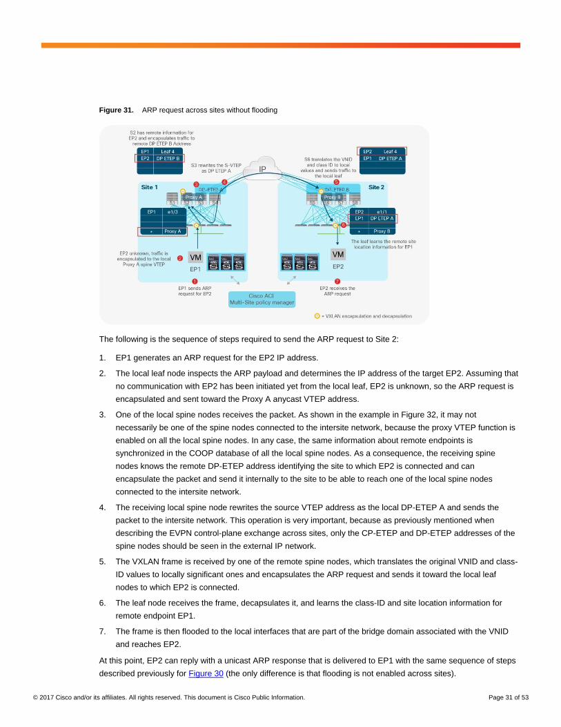
Figure 31. ARP request across sites without flooding
The following is the sequence of steps required to send the ARP request to Site 2:
1. EP1 generates an ARP request for the EP2 IP address.
2. The local leaf node inspects the ARP payload and determines the IP address of the target EP2. Assuming that
no communication with EP2 has been initiated yet from the local leaf, EP2 is unknown, so the ARP request is
encapsulated and sent toward the Proxy A anycast VTEP address.
3. One of the local spine nodes receives the packet. As shown in the example in Figure 32, it may not
necessarily be one of the spine nodes connected to the intersite network, because the proxy VTEP function is
enabled on all the local spine nodes. In any case, the same information about remote endpoints is
synchronized in the COOP database of all the local spine nodes. As a consequence, the receiving spine
nodes knows the remote DP-ETEP address identifying the site to which EP2 is connected and can
encapsulate the packet and send it internally to the site to be able to reach one of the local spine nodes
connected to the intersite network.
4. The receiving local spine node rewrites the source VTEP address as the local DP-ETEP A and sends the
packet to the intersite network. This operation is very important, because as previously mentioned when
describing the EVPN control-plane exchange across sites, only the CP-ETEP and DP-ETEP addresses of the
spine nodes should be seen in the external IP network.
5. The VXLAN frame is received by one of the remote spine nodes, which translates the original VNID and class-
ID values to locally significant ones and encapsulates the ARP request and sends it toward the local leaf
nodes to which EP2 is connected.
6. The leaf node receives the frame, decapsulates it, and learns the class-ID and site location information for
remote endpoint EP1.
7. The frame is then flooded to the local interfaces that are part of the bridge domain associated with the VNID
and reaches EP2.
At this point, EP2 can reply with a unicast ARP response that is delivered to EP1 with the same sequence of steps
described previously for Figure 30 (the only difference is that flooding is not enabled across sites).
© 2017 Cisco and/or its affiliates. All rights reserved. This document is Cisco Public Information. Page 32 of 53
Note: Disabling flooding by de-selecting the “InterSiteBUMTrafficAllow” flag for a given bridge domain on the Multi-
Site policy manager has also implications on how the other types of Layer 2 BUM traffic are handled. Specifically,
Layer 2 unknown unicast traffic is handled as ARP (as described above), whereas Layer 2 broadcast and multicast
traffic is flooded in the bridge domain intrasite but it is not sent intersite.
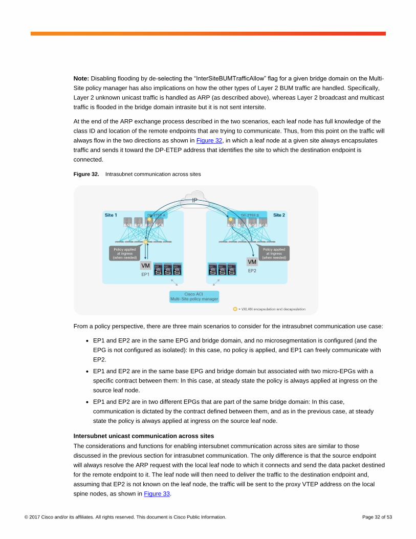
At the end of the ARP exchange process described in the two scenarios, each leaf node has full knowledge of the
class ID and location of the remote endpoints that are trying to communicate. Thus, from this point on the traffic will
always flow in the two directions as shown in Figure 32, in which a leaf node at a given site always encapsulates
traffic and sends it toward the DP-ETEP address that identifies the site to which the destination endpoint is
connected.
Figure 32. Intrasubnet communication across sites
From a policy perspective, there are three main scenarios to consider for the intrasubnet communication use case:
● EP1 and EP2 are in the same EPG and bridge domain, and no microsegmentation is configured (and the
EPG is not configured as isolated): In this case, no policy is applied, and EP1 can freely communicate with
EP2.
● EP1 and EP2 are in the same base EPG and bridge domain but associated with two micro-EPGs with a
specific contract between them: In this case, at steady state the policy is always applied at ingress on the
source leaf node.
● EP1 and EP2 are in two different EPGs that are part of the same bridge domain: In this case,
communication is dictated by the contract defined between them, and as in the previous case, at steady
state the policy is always applied at ingress on the source leaf node.
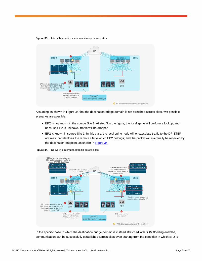
Intersubnet unicast communication across sites
The considerations and functions for enabling intersubnet communication across sites are similar to those
discussed in the previous section for intrasubnet communication. The only difference is that the source endpoint
will always resolve the ARP request with the local leaf node to which it connects and send the data packet destined
for the remote endpoint to it. The leaf node will then need to deliver the traffic to the destination endpoint and,
assuming that EP2 is not known on the leaf node, the traffic will be sent to the proxy VTEP address on the local
spine nodes, as shown in Figure 33.
© 2017 Cisco and/or its affiliates. All rights reserved. This document is Cisco Public Information. Page 33 of 53
Figure 33. Intersubnet unicast communication across sites
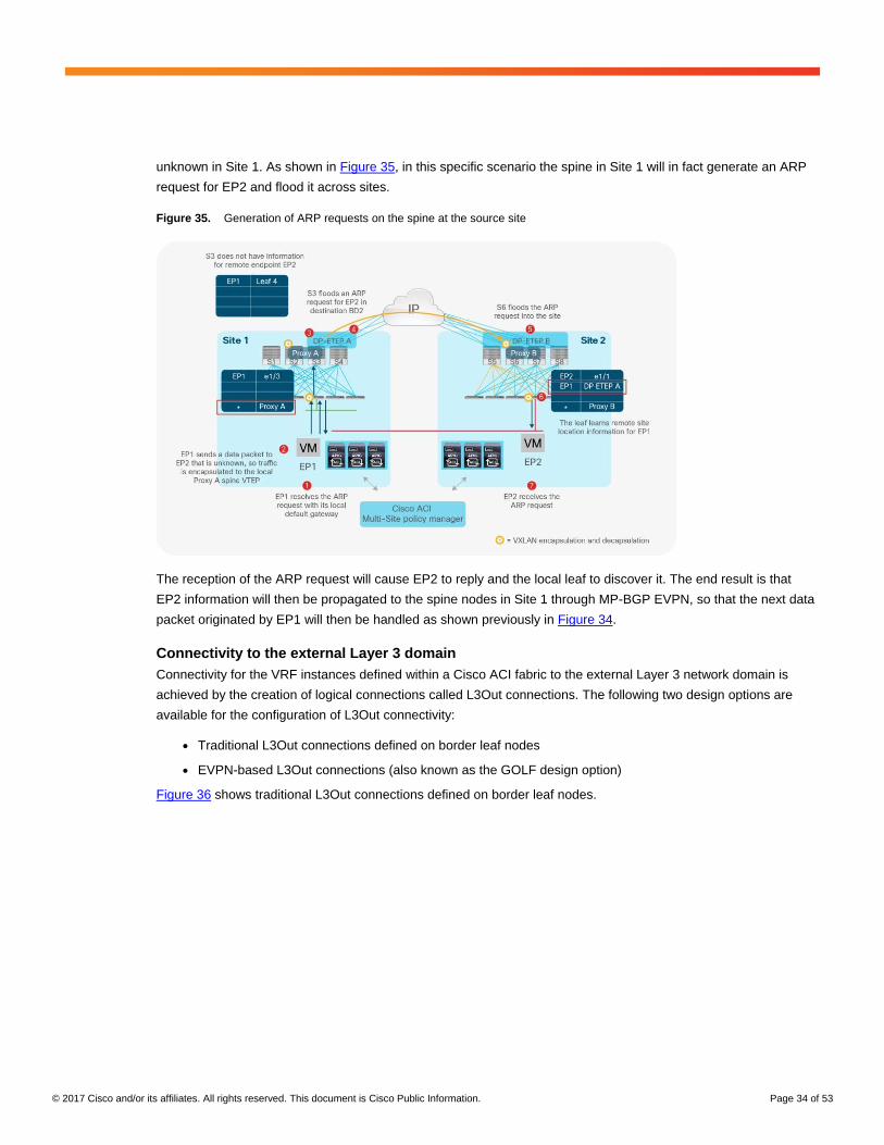
Assuming as shown in Figure 34 that the destination bridge domain is not stretched across sites, two possible
scenarios are possible:
● EP2 is not known in the source Site 1: At step 3 in the figure, the local spine will perform a lookup, and
because EP2 is unknown, traffic will be dropped.
● EP2 is known in source Site 1: In this case, the local spine node will encapsulate traffic to the DP-ETEP
address that identifies the remote site to which EP2 belongs, and the packet will eventually be received by
the destination endpoint, as shown in Figure 34.
Figure 34. Delivering intersubnet traffic across sites
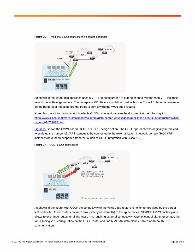
In the specific case in which the destination bridge domain is instead stretched with BUM flooding enabled,
communication can be successfully established across sites even starting from the condition in which EP2 is
© 2017 Cisco and/or its affiliates. All rights reserved. This document is Cisco Public Information. Page 34 of 53
unknown in Site 1. As shown in Figure 35, in this specific scenario the spine in Site 1 will in fact generate an ARP
request for EP2 and flood it across sites.
Figure 35. Generation of ARP requests on the spine at the source site
The reception of the ARP request will cause EP2 to reply and the local leaf to discover it. The end result is that
EP2 information will then be propagated to the spine nodes in Site 1 through MP-BGP EVPN, so that the next data
packet originated by EP1 will then be handled as shown previously in Figure 34.
Connectivity to the external Layer 3 domain
Connectivity for the VRF instances defined within a Cisco ACI fabric to the external Layer 3 network domain is
achieved by the creation of logical connections called L3Out connections. The following two design options are
available for the configuration of L3Out connectivity:
● Traditional L3Out connections defined on border leaf nodes
● EVPN-based L3Out connections (also known as the GOLF design option)
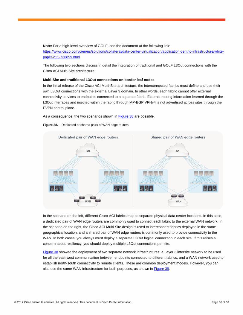
Figure 36 shows traditional L3Out connections defined on border leaf nodes.
© 2017 Cisco and/or its affiliates. All rights reserved. This document is Cisco Public Information. Page 35 of 53
Figure 36. Traditional L3Out connections on border leaf nodes
As shown in the figure, this approach uses a VRF-Lite configuration to extend connectivity for each VRF instance
toward the WAN edge routers. The data-plane VXLAN encapsulation used within the Cisco ACI fabric is terminated
on the border leaf nodes before the traffic is sent toward the WAN edge routers.
Note: For more information about border leaf L3Out connections, see the document at the following link:
https://www.cisco.com/c/en/us/solutions/collateral/data-center-virtualization/application-centric-infrastructure/white-
paper-c07-732033.html.
Figure 37 shows the EVPN-based L3Out, or GOLF, design option. The GOLF approach was originally introduced
to scale up the number of VRF instances to be connected to the external Layer 3 network domain (1000 VRF
instances have been supported from the launch of GOLF integration with Cisco ACI)
Figure 37. GOLF L3Out connections
As shown in the figure, with GOLF the connectivity to the WAN edge routers is no longer provided by the border
leaf nodes, but these routers connect now (directly or indirectly) to the spine nodes. MP-BGP EVPN control plane
allows to exchange routes for all the ACI VRFs requiring external connectivity, OpFlex control plane automates the
fabric facing VRF configuration on the GOLF router and finally VXLAN data plane enables north-south
communication.
© 2017 Cisco and/or its affiliates. All rights reserved. This document is Cisco Public Information. Page 36 of 53
Note: For a high-level overview of GOLF, see the document at the following link:
https://www.cisco.com/c/en/us/solutions/collateral/data-center-virtualization/application-centric-infrastructure/white-
paper-c11-736899.html.
The following two sections discuss in detail the integration of traditional and GOLF L3Out connections with the
Cisco ACI Multi-Site architecture.
Multi-Site and traditional L3Out connections on border leaf nodes
In the initial release of the Cisco ACI Multi-Site architecture, the interconnected fabrics must define and use their
own L3Out connections with the external Layer 3 domain. In other words, each fabric cannot offer external
connectivity services to endpoints connected to a separate fabric. External routing information learned through the
L3Out interfaces and injected within the fabric through MP-BGP VPNv4 is not advertised across sites through the
EVPN control plane.
As a consequence, the two scenarios shown in Figure 38 are possible.
Figure 38. Dedicated or shared pairs of WAN edge routers
In the scenario on the left, different Cisco ACI fabrics map to separate physical data center locations. In this case,
a dedicated pair of WAN edge routers are commonly used to connect each fabric to the external WAN network. In
the scenario on the right, the Cisco ACI Multi-Site design is used to interconnect fabrics deployed in the same
geographical location, and a shared pair of WAN edge routers is commonly used to provide connectivity to the
WAN. In both cases, you always must deploy a separate L3Out logical connection in each site. If this raises a
concern about resiliency, you should deploy multiple L3Out connections per site.
Figure 38 showed the deployment of two separate network infrastructures: a Layer 3 intersite network to be used
for all the east-west communication between endpoints connected to different fabrics, and a WAN network used to
establish north-south connectivity to remote clients. These are common deployment models. However, you can
also use the same WAN infrastructure for both purposes, as shown in Figure 39.
© 2017 Cisco and/or its affiliates. All rights reserved. This document is Cisco Public Information. Page 37 of 53
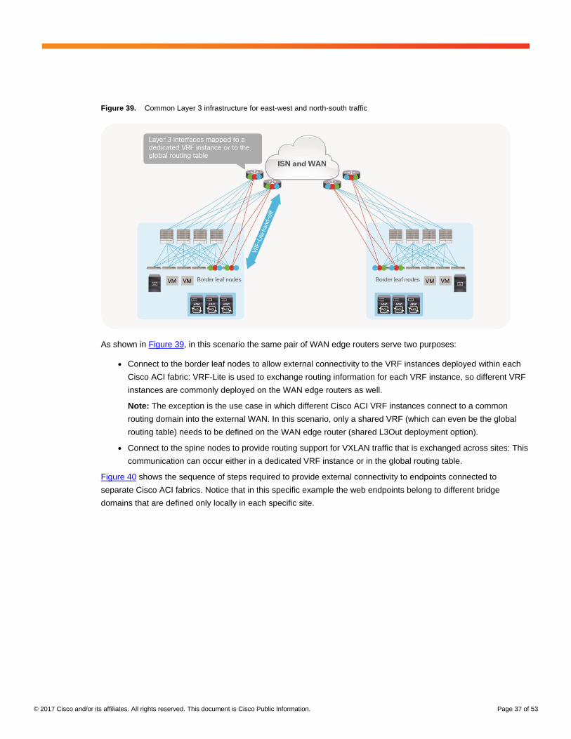
Figure 39. Common Layer 3 infrastructure for east-west and north-south traffic
As shown in Figure 39, in this scenario the same pair of WAN edge routers serve two purposes:
● Connect to the border leaf nodes to allow external connectivity to the VRF instances deployed within each
Cisco ACI fabric: VRF-Lite is used to exchange routing information for each VRF instance, so different VRF
instances are commonly deployed on the WAN edge routers as well.
Note: The exception is the use case in which different Cisco ACI VRF instances connect to a common
routing domain into the external WAN. In this scenario, only a shared VRF (which can even be the global
routing table) needs to be defined on the WAN edge router (shared L3Out deployment option).
● Connect to the spine nodes to provide routing support for VXLAN traffic that is exchanged across sites: This
communication can occur either in a dedicated VRF instance or in the global routing table.
Figure 40 shows the sequence of steps required to provide external connectivity to endpoints connected to
separate Cisco ACI fabrics. Notice that in this specific example the web endpoints belong to different bridge
domains that are defined only locally in each specific site.
© 2017 Cisco and/or its affiliates. All rights reserved. This document is Cisco Public Information. Page 38 of 53
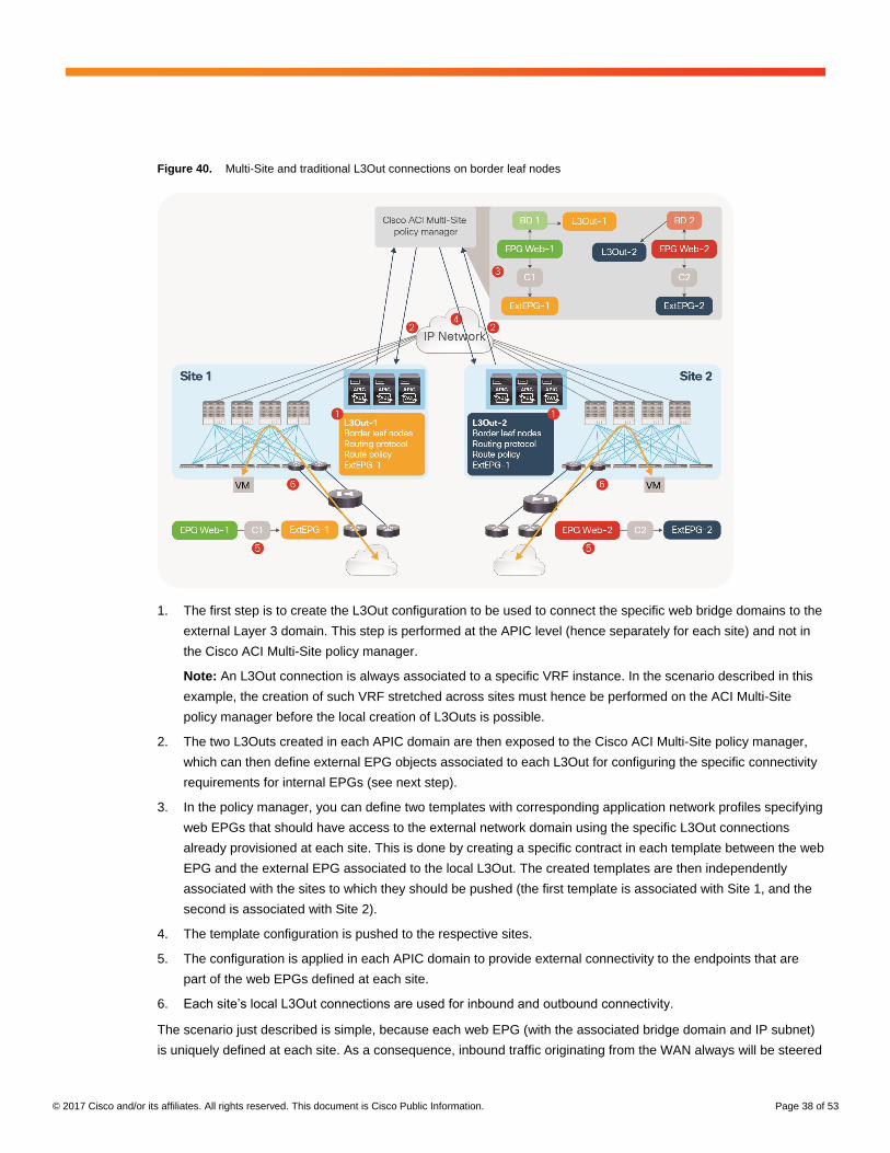
Figure 40. Multi-Site and traditional L3Out connections on border leaf nodes
1. The first step is to create the L3Out configuration to be used to connect the specific web bridge domains to the
external Layer 3 domain. This step is performed at the APIC level (hence separately for each site) and not in
the Cisco ACI Multi-Site policy manager.
Note: An L3Out connection is always associated to a specific VRF instance. In the scenario described in this
example, the creation of such VRF stretched across sites must hence be performed on the ACI Multi-Site
policy manager before the local creation of L3Outs is possible.
2. The two L3Outs created in each APIC domain are then exposed to the Cisco ACI Multi-Site policy manager,
which can then define external EPG objects associated to each L3Out for configuring the specific connectivity
requirements for internal EPGs (see next step).
3. In the policy manager, you can define two templates with corresponding application network profiles specifying
web EPGs that should have access to the external network domain using the specific L3Out connections
already provisioned at each site. This is done by creating a specific contract in each template between the web
EPG and the external EPG associated to the local L3Out. The created templates are then independently
associated with the sites to which they should be pushed (the first template is associated with Site 1, and the
second is associated with Site 2).
4. The template configuration is pushed to the respective sites.
5. The configuration is applied in each APIC domain to provide external connectivity to the endpoints that are
part of the web EPGs defined at each site.
6. Each site’s local L3Out connections are used for inbound and outbound connectivity.
The scenario just described is simple, because each web EPG (with the associated bridge domain and IP subnet)
is uniquely defined at each site. As a consequence, inbound traffic originating from the WAN always will be steered

© 2017 Cisco and/or its affiliates. All rights reserved. This document is Cisco Public Information. Page 39 of 53
to the specific site at which the web destination endpoint is located, and flows always will traverse in a symmetric
fashion the perimeter firewall that can be deployed between the WAN and each Cisco ACI site.
A different behavior occurs if the web EPG is associated with a bridge domain that is stretched across sites, as
shown in Figure 41.
Figure 41. Multi-Site and traditional L3Out connections with a stretched bridge domain
In this case, a different L3Out connection is defined at each site, but the template created in the Multi-Site policy
manager associates the same web EPG with both, because the web endpoints can be connected in the same
bridge domain stretched across sites. As a consequence, the same web prefix will be advertised to both sites, and
inbound traffic may be delivered to the border leaf nodes of Site 1 even if the destination endpoint is connected in
Site 2. In that case, the policy manager will handle the delivery of the traffic to the endpoint, but the return flow
toward the WAN will use the local L3Out connection in Site 2. This approach will cause traffic drops if a stateful
firewall device (independent from the one deployed in site 1) is deployed to protect the perimeter of the Cisco ACI
site 2.
A possible solution to this problem is the use of GOLF L3Out connections, as discussed in the next section.
Multi-Site and GOLF L3Out connections
Even when GOLF is used to connect to the external Layer 3 domain, you can deploy a dedicated or a shared pair
of GOLF routers to serve different fabrics, as shown in Figure 42.
© 2017 Cisco and/or its affiliates. All rights reserved. This document is Cisco Public Information. Page 40 of 53
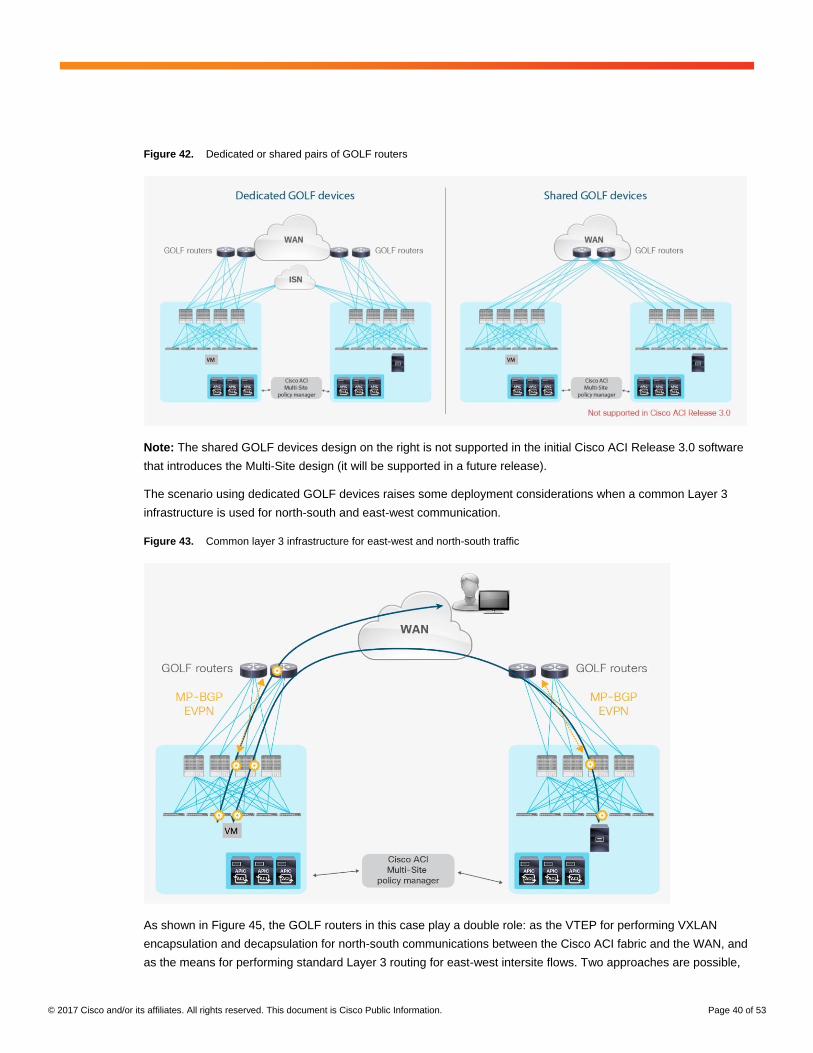
Figure 42. Dedicated or shared pairs of GOLF routers
Note: The shared GOLF devices design on the right is not supported in the initial Cisco ACI Release 3.0 software
that introduces the Multi-Site design (it will be supported in a future release).
The scenario using dedicated GOLF devices raises some deployment considerations when a common Layer 3
infrastructure is used for north-south and east-west communication.
Figure 43. Common layer 3 infrastructure for east-west and north-south traffic
As shown in Figure 45, the GOLF routers in this case play a double role: as the VTEP for performing VXLAN
encapsulation and decapsulation for north-south communications between the Cisco ACI fabric and the WAN, and
as the means for performing standard Layer 3 routing for east-west intersite flows. Two approaches are possible,
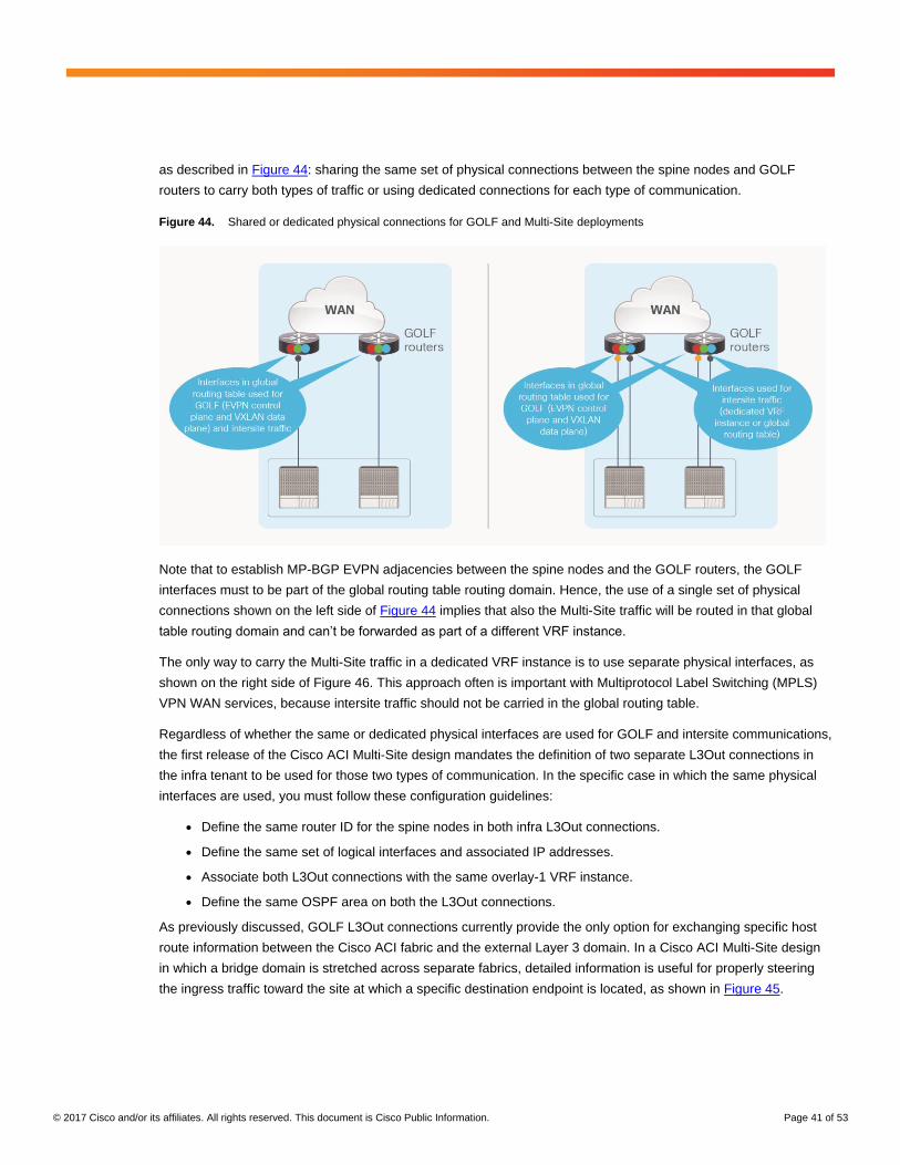
© 2017 Cisco and/or its affiliates. All rights reserved. This document is Cisco Public Information. Page 41 of 53
as described in Figure 44: sharing the same set of physical connections between the spine nodes and GOLF
routers to carry both types of traffic or using dedicated connections for each type of communication.
Figure 44. Shared or dedicated physical connections for GOLF and Multi-Site deployments
Note that to establish MP-BGP EVPN adjacencies between the spine nodes and the GOLF routers, the GOLF
interfaces must to be part of the global routing table routing domain. Hence, the use of a single set of physical
connections shown on the left side of Figure 44 implies that also the Multi-Site traffic will be routed in that global
table routing domain and can’t be forwarded as part of a different VRF instance.
The only way to carry the Multi-Site traffic in a dedicated VRF instance is to use separate physical interfaces, as
shown on the right side of Figure 46. This approach often is important with Multiprotocol Label Switching (MPLS)
VPN WAN services, because intersite traffic should not be carried in the global routing table.
Regardless of whether the same or dedicated physical interfaces are used for GOLF and intersite communications,
the first release of the Cisco ACI Multi-Site design mandates the definition of two separate L3Out connections in
the infra tenant to be used for those two types of communication. In the specific case in which the same physical
interfaces are used, you must follow these configuration guidelines:
● Define the same router ID for the spine nodes in both infra L3Out connections.
● Define the same set of logical interfaces and associated IP addresses.
● Associate both L3Out connections with the same overlay-1 VRF instance.
● Define the same OSPF area on both the L3Out connections.
As previously discussed, GOLF L3Out connections currently provide the only option for exchanging specific host
route information between the Cisco ACI fabric and the external Layer 3 domain. In a Cisco ACI Multi-Site design
in which a bridge domain is stretched across separate fabrics, detailed information is useful for properly steering
the ingress traffic toward the site at which a specific destination endpoint is located, as shown in Figure 45.
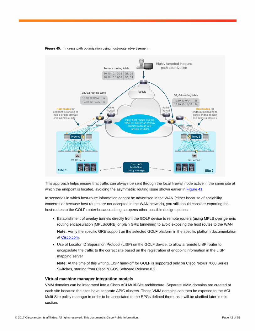
© 2017 Cisco and/or its affiliates. All rights reserved. This document is Cisco Public Information. Page 42 of 53
Figure 45. Ingress path optimization using host-route advertisement
This approach helps ensure that traffic can always be sent through the local firewall node active in the same site at
which the endpoint is located, avoiding the asymmetric routing issue shown earlier in Figure 41.
In scenarios in which host-route information cannot be advertised in the WAN (either because of scalability
concerns or because host routes are not accepted in the WAN network), you still should consider exporting the
host routes to the GOLF router because doing so opens other possible design options:
● Establishment of overlay tunnels directly from the GOLF device to remote routers (using MPLS over generic
routing encapsulation [MPLSoGRE] or plain GRE tunneling) to avoid exposing the host routes to the WAN
Note: Verify the specific GRE support on the selected GOLF platform in the specific platform documentation
at Cisco.com.
● Use of Locator ID Separation Protocol (LISP) on the GOLF device, to allow a remote LISP router to
encapsulate the traffic to the correct site based on the registration of endpoint information in the LISP
mapping server
Note: At the time of this writing, LISP hand-off for GOLF is supported only on Cisco Nexus 7000 Series
Switches, starting from Cisco NX-OS Software Release 8.2.
Virtual machine manager integration models
VMM domains can be integrated into a Cisco ACI Multi-Site architecture. Separate VMM domains are created at
each site because the sites have separate APIC clusters. Those VMM domains can then be exposed to the ACI
Multi-Site policy manager in order to be associated to the EPGs defined there, as it will be clarified later in this
section.
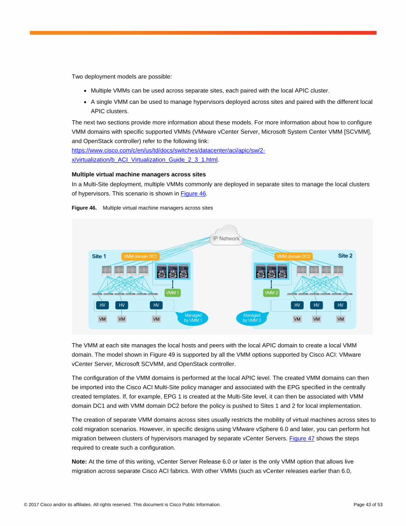
© 2017 Cisco and/or its affiliates. All rights reserved. This document is Cisco Public Information. Page 43 of 53
Two deployment models are possible:
● Multiple VMMs can be used across separate sites, each paired with the local APIC cluster.
● A single VMM can be used to manage hypervisors deployed across sites and paired with the different local
APIC clusters.
The next two sections provide more information about these models. For more information about how to configure
VMM domains with specific supported VMMs (VMware vCenter Server, Microsoft System Center VMM [SCVMM],
and OpenStack controller) refer to the following link:
https://www.cisco.com/c/en/us/td/docs/switches/datacenter/aci/apic/sw/2-
x/virtualization/b_ACI_Virtualization_Guide_2_3_1.html.
Multiple virtual machine managers across sites
In a Multi-Site deployment, multiple VMMs commonly are deployed in separate sites to manage the local clusters
of hypervisors. This scenario is shown in Figure 46.
Figure 46. Multiple virtual machine managers across sites
The VMM at each site manages the local hosts and peers with the local APIC domain to create a local VMM
domain. The model shown in Figure 49 is supported by all the VMM options supported by Cisco ACI: VMware
vCenter Server, Microsoft SCVMM, and OpenStack controller.
The configuration of the VMM domains is performed at the local APIC level. The created VMM domains can then
be imported into the Cisco ACI Multi-Site policy manager and associated with the EPG specified in the centrally
created templates. If, for example, EPG 1 is created at the Multi-Site level, it can then be associated with VMM
domain DC1 and with VMM domain DC2 before the policy is pushed to Sites 1 and 2 for local implementation.
The creation of separate VMM domains across sites usually restricts the mobility of virtual machines across sites to
cold migration scenarios. However, in specific designs using VMware vSphere 6.0 and later, you can perform hot
migration between clusters of hypervisors managed by separate vCenter Servers. Figure 47 shows the steps
required to create such a configuration.
Note: At the time of this writing, vCenter Server Release 6.0 or later is the only VMM option that allows live
migration across separate Cisco ACI fabrics. With other VMMs (such as vCenter releases earlier than 6.0,
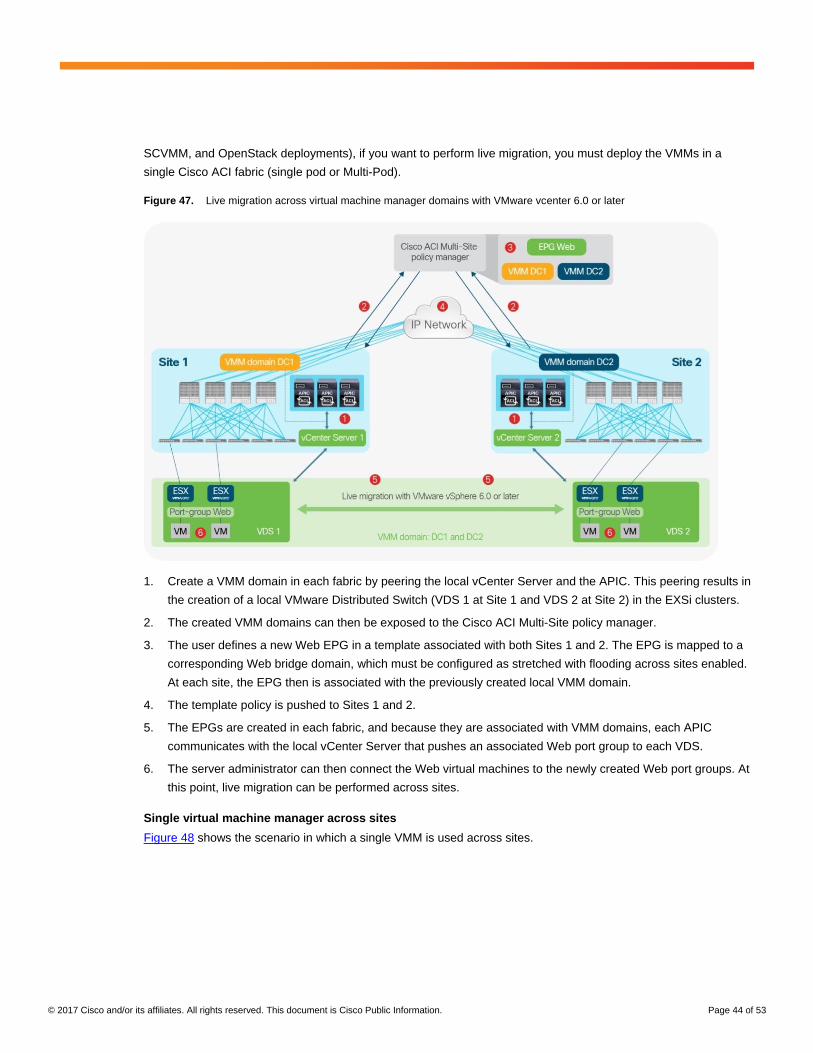
© 2017 Cisco and/or its affiliates. All rights reserved. This document is Cisco Public Information. Page 44 of 53
SCVMM, and OpenStack deployments), if you want to perform live migration, you must deploy the VMMs in a
single Cisco ACI fabric (single pod or Multi-Pod).
Figure 47. Live migration across virtual machine manager domains with VMware vcenter 6.0 or later
1. Create a VMM domain in each fabric by peering the local vCenter Server and the APIC. This peering results in
the creation of a local VMware Distributed Switch (VDS 1 at Site 1 and VDS 2 at Site 2) in the EXSi clusters.
2. The created VMM domains can then be exposed to the Cisco ACI Multi-Site policy manager.
3. The user defines a new Web EPG in a template associated with both Sites 1 and 2. The EPG is mapped to a
corresponding Web bridge domain, which must be configured as stretched with flooding across sites enabled.
At each site, the EPG then is associated with the previously created local VMM domain.
4. The template policy is pushed to Sites 1 and 2.
5. The EPGs are created in each fabric, and because they are associated with VMM domains, each APIC
communicates with the local vCenter Server that pushes an associated Web port group to each VDS.
6. The server administrator can then connect the Web virtual machines to the newly created Web port groups. At
this point, live migration can be performed across sites.
Single virtual machine manager across sites
Figure 48 shows the scenario in which a single VMM is used across sites.
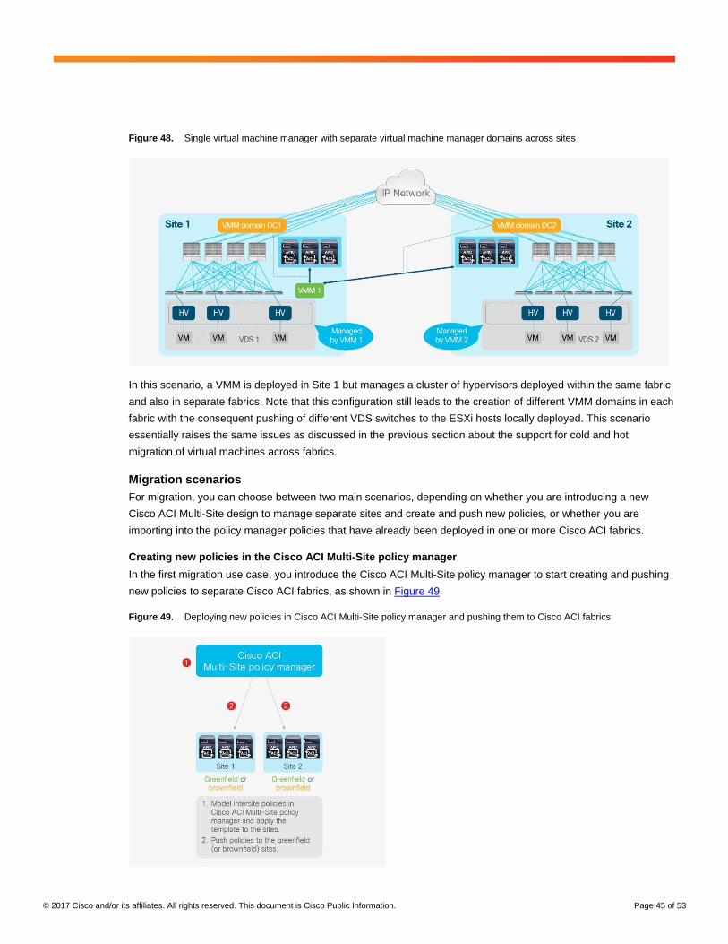
© 2017 Cisco and/or its affiliates. All rights reserved. This document is Cisco Public Information. Page 45 of 53
Figure 48. Single virtual machine manager with separate virtual machine manager domains across sites
In this scenario, a VMM is deployed in Site 1 but manages a cluster of hypervisors deployed within the same fabric
and also in separate fabrics. Note that this configuration still leads to the creation of different VMM domains in each
fabric with the consequent pushing of different VDS switches to the ESXi hosts locally deployed. This scenario
essentially raises the same issues as discussed in the previous section about the support for cold and hot
migration of virtual machines across fabrics.
Migration scenarios
For migration, you can choose between two main scenarios, depending on whether you are introducing a new
Cisco ACI Multi-Site design to manage separate sites and create and push new policies, or whether you are
importing into the policy manager policies that have already been deployed in one or more Cisco ACI fabrics.
Creating new policies in the Cisco ACI Multi-Site policy manager
In the first migration use case, you introduce the Cisco ACI Multi-Site policy manager to start creating and pushing
new policies to separate Cisco ACI fabrics, as shown in Figure 49.
Figure 49. Deploying new policies in Cisco ACI Multi-Site policy manager and pushing them to Cisco ACI fabrics
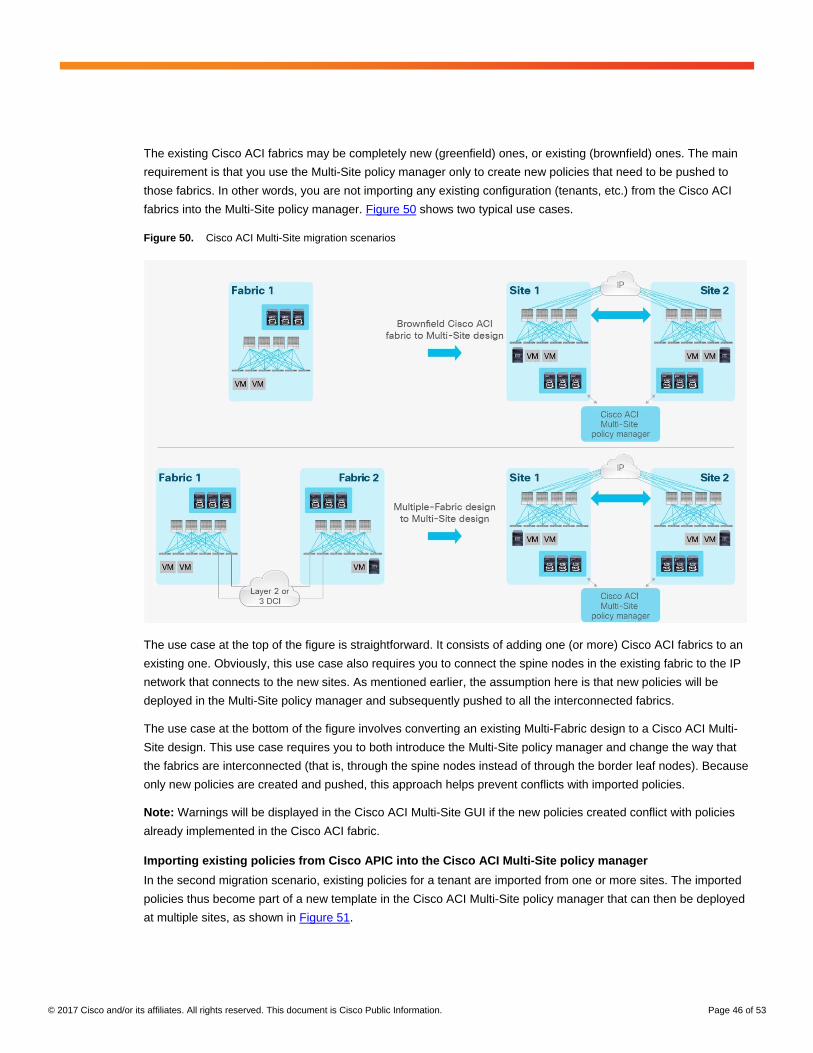
© 2017 Cisco and/or its affiliates. All rights reserved. This document is Cisco Public Information. Page 46 of 53
The existing Cisco ACI fabrics may be completely new (greenfield) ones, or existing (brownfield) ones. The main
requirement is that you use the Multi-Site policy manager only to create new policies that need to be pushed to
those fabrics. In other words, you are not importing any existing configuration (tenants, etc.) from the Cisco ACI
fabrics into the Multi-Site policy manager. Figure 50 shows two typical use cases.
Figure 50. Cisco ACI Multi-Site migration scenarios
The use case at the top of the figure is straightforward. It consists of adding one (or more) Cisco ACI fabrics to an
existing one. Obviously, this use case also requires you to connect the spine nodes in the existing fabric to the IP
network that connects to the new sites. As mentioned earlier, the assumption here is that new policies will be
deployed in the Multi-Site policy manager and subsequently pushed to all the interconnected fabrics.
The use case at the bottom of the figure involves converting an existing Multi-Fabric design to a Cisco ACI Multi-
Site design. This use case requires you to both introduce the Multi-Site policy manager and change the way that
the fabrics are interconnected (that is, through the spine nodes instead of through the border leaf nodes). Because
only new policies are created and pushed, this approach helps prevent conflicts with imported policies.
Note: Warnings will be displayed in the Cisco ACI Multi-Site GUI if the new policies created conflict with policies
already implemented in the Cisco ACI fabric.
Importing existing policies from Cisco APIC into the Cisco ACI Multi-Site policy manager
In the second migration scenario, existing policies for a tenant are imported from one or more sites. The imported
policies thus become part of a new template in the Cisco ACI Multi-Site policy manager that can then be deployed
at multiple sites, as shown in Figure 51.
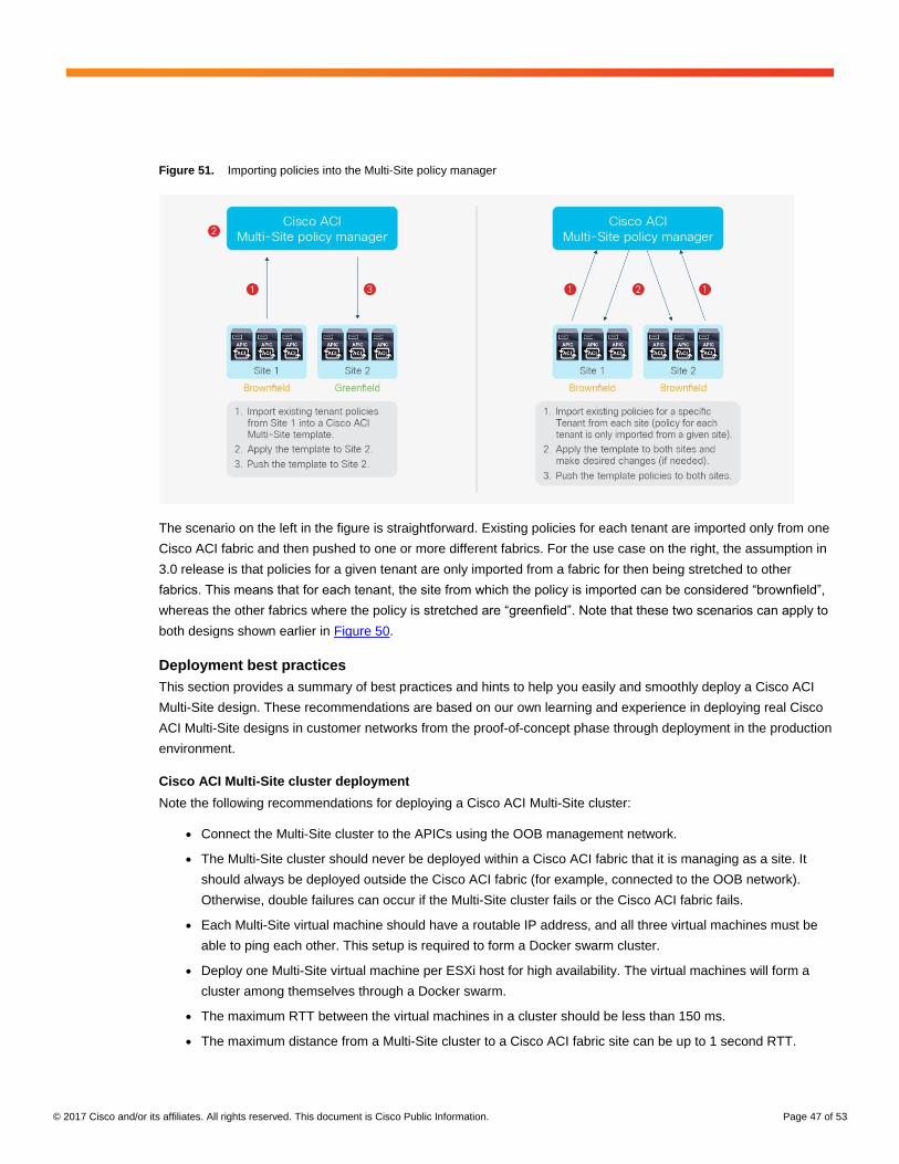
© 2017 Cisco and/or its affiliates. All rights reserved. This document is Cisco Public Information. Page 47 of 53
Figure 51. Importing policies into the Multi-Site policy manager
The scenario on the left in the figure is straightforward. Existing policies for each tenant are imported only from one
Cisco ACI fabric and then pushed to one or more different fabrics. For the use case on the right, the assumption in
3.0 release is that policies for a given tenant are only imported from a fabric for then being stretched to other
fabrics. This means that for each tenant, the site from which the policy is imported can be considered “brownfield”,
whereas the other fabrics where the policy is stretched are “greenfield”. Note that these two scenarios can apply to
both designs shown earlier in Figure 50.
Deployment best practices
This section provides a summary of best practices and hints to help you easily and smoothly deploy a Cisco ACI
Multi-Site design. These recommendations are based on our own learning and experience in deploying real Cisco
ACI Multi-Site designs in customer networks from the proof-of-concept phase through deployment in the production
environment.
Cisco ACI Multi-Site cluster deployment
Note the following recommendations for deploying a Cisco ACI Multi-Site cluster:
● Connect the Multi-Site cluster to the APICs using the OOB management network.
● The Multi-Site cluster should never be deployed within a Cisco ACI fabric that it is managing as a site. It
should always be deployed outside the Cisco ACI fabric (for example, connected to the OOB network).
Otherwise, double failures can occur if the Multi-Site cluster fails or the Cisco ACI fabric fails.
● Each Multi-Site virtual machine should have a routable IP address, and all three virtual machines must be
able to ping each other. This setup is required to form a Docker swarm cluster.
● Deploy one Multi-Site virtual machine per ESXi host for high availability. The virtual machines will form a
cluster among themselves through a Docker swarm.
● The maximum RTT between the virtual machines in a cluster should be less than 150 ms.
● The maximum distance from a Multi-Site cluster to a Cisco ACI fabric site can be up to 1 second RTT.
© 2017 Cisco and/or its affiliates. All rights reserved. This document is Cisco Public Information. Page 48 of 53
● A Multi-Site cluster uses the following ports for the internal control plane and data plane, so the underlay
network should always ensure that these ports are open (in the case of an ACL configuration of a firewall
deployment in the network):
◦ TCP port 2377 for cluster management communication
◦ TCP and UDP port 7946 for communication among nodes
◦ UDP port 4789 for overlay network traffic
◦ TCP port 443 for Multi-Site policy manager User Interface (UI)
◦ IP 50 Encapsulating Security Protocol (ESP) for encryption
● IPsec is used to encrypt all intra–Multi-Site cluster control-plane and data-plane traffic to provide security
because the virtual machines can be placed up to 150 ms RTT apart.
● The minimum specifications for Multi-Site virtual machines are ESXi 5.5 or later, four vCPUs, 8 GB of RAM,
and a 5-GB disk.
Day-0 Multi-Site infrastructure configuration
Here are the recommended best practices for deploying Multi-Site connectivity across separate fabrics:
● All the physical interfaces connecting the spine nodes to the intersite network must be on Cisco Nexus EX
platform line cards (or a newer generation). Generation-1 spine nodes are not supported and can be used
only for intra-fabric communication.
● The APIC fabric ID in a Multi-Site deployment can be unique, or the same value can be used across sites
for greenfield or brownfield deployments. In scenario where shared GOLF devices are not deployed
between different sites, the recommendation is to keep the Fabric ID 1 across all sites. If shared GOLF is
required (once supported) there are theree possible scenarios:
1. Auto-RT is not configured: the recommendation is to keep Fabric ID 1 across all sites.
2. Auto-RT is enabled and the sites are part of unique BGP ASN: the recommendation is to keep Fabric
ID 1 across all sites.
3. Auto-RT is enabled and the sites are part of the same BGP ASN: the recommendation is to use unique
fabric IDs across sites.
● The Cisco ACI Multi-Site site ID or site name must be unique across all sites. This parameter is configured
directly on the Multi-Site policy manager.
● The Cisco ACI Multi-Site site ID (not the site name) cannot be changed after it has been assigned. To
reconfigure the site ID, you will need to perform a clean wipe to return to the factory defaults.
Note: The APIC site ID is different from the Cisco ACI fabric ID assigned on the APIC.
● In ACI Multi-Site, always undeploy a schema-template from a site before removing from a site.
● The configured fabric TEP pools should be unique and not overlapping across sites.
● All Multi-Site control-plane and data-plane TEPs should be externally routable over ISN.
● Four types of TEP addresses need to be configured:
◦ Multi-Pod data-plane TEP: Configure this address directly on each APIC cluster in Cisco ACI
Release 3.0.
◦ This configuration is mandatory even if Multi-Pod fabrics are not initially supported in a Cisco ACI
Multi-Site architecture.
© 2017 Cisco and/or its affiliates. All rights reserved. This document is Cisco Public Information. Page 49 of 53
◦ This address will be configurable from the Cisco ACI Multi-Site deployment after Multi-Pod and Multi-
Site support are added in the future.
◦ External data-plane multicast TEP (HER-ETEP):
◦ This address is used as the destination IP address for BUM traffic sent across the fabric in head-end
replication (or HER) mode.
◦ External data-plane unicast TEP (DP-ETEP):
◦ This address is used as the anycast VTEP address for each pod.
◦ Configure one address per pod.
◦ This address is used as the next-hop on the local spine node to reach remote endpoints.
◦ In Cisco ACI Release 3.0, the same IP address can be configured as Multi-Site DP-ETEP and Multi-
Pod data-plane TEP.
◦ External control-plane TEP (CP-ETEP):
◦ This address is used to form MP-BGP EVPN sessions.
◦ Define one unique IP address per spine node.
● Allocate at least two spine nodes for Multi-Site BGP-EVPN peering in an Cisco ACI pod (for redundancy).
Note that not all the spine nodes need to be BGP-EVPN peers.
● We recommend use full-mesh BGP-EVPN peering instead of route reflectors since it represents a simpler
approach, and at FCS only five sites are supported, so full-mesh peering is fine to use. BGP-EVPN will
automatically form full-mesh iBGP and eBGP peerings.
● When route reflectors are used, they will apply to iBGP sessions only within the Autonomous System
Number (ASN), and eBGP will still use full mesh between ASNs. A spine node can support both types of
peering at the same time.
● When deploying Route Reflector (RR) with high availability for N sites, you can deploy 1 RR instance on a
spine node in a site and deploy this across 3 sites which would cover high availability requirement for N
sites instead of deploying 1 RR instance in every site.
● Use BGP and OSPF default general settings for Multi-Site ISN.
● Check to ensure that the Time-To-Live (TTL) setting is large enough if the sessions are eBGP (the default
is 16).
● Make sure that the source interface for the intersite BGP-EVPN sessions is configured with the control-
plane TEP (with the infra L3Out connection assigned to the right loopback connector).
● Use separate infra L3Out connections for GOLF and Multi-Site connectivity. The infra L3Out connection
used for GOLF must be configured directly on the APIC (it can’t be configured in the Multi-Site policy
manager).
● Verify that the secure BGP passwords match in the various sites (if configured).
● The BGP community sample format is extended:as2-nn4:4:15.
© 2017 Cisco and/or its affiliates. All rights reserved. This document is Cisco Public Information. Page 50 of 53
General best practices for Cisco ACI Multi-Site design
Note the following lessons learned from trials and initial deployments of Cisco ACI Multi-Site designs:
● If WAN connectivity is over GOLF, you need to consider two scenarios:
◦ Scenario 1: Site 1 has its own nonstretched BD1 and Subnet 1 and GOLF L3Out-1 connection, and Site
2 has its own nonstretched BD2 and Subnet 2 and GOLF L3Out-2 connection. Each GOLF L3Out
connection advertises its own bridge domain subnet to its own GOLF router, so host routing is not
required.
◦ Scenario 2:
BD1 and Subnet 1 is stretched to Sites 1 and 2.
The Layer 2 stretch flag is enabled.
InterSiteBUMTrafficAllow can be enabled or disabled.
Each site also has its own local GOLF L3Out connection, which advertises the subnet through its
GOLF L3Out connection to its GOLF router.
The subnet in the WAN will have an equal-cost multipath (ECMP) path to the two GOLF routers.
To avoid suboptimal routing of traffic across sites, host routing can be used for stretched bridge
domain and subnet cases.
Suboptimal routing of GOLF traffic over IPN is not supported. This means that traffic cannot be
delivered from the GOLF router to a specific site and then be redirected to a separate site to reach a
remote destination endpoint.
● Intersite VXLAN tunnels must transit through the ISN and cannot use another site for transit. As a
consequence, you must build enough redundancy into the ISN to help ensure that two given sites are
always connected through the ISN in any node or link failure scenario.
● Each site must deploy a local L3Out connection:
◦ A site cannot provide transit routing services for a different site.
◦ A pair of WAN edge routers can be shared across sites (traditional L3Out connection on border leaf
nodes).
◦ Shared WAN edge routers across sites are not supported in the first Cisco ACI Multi-Site release when
GOLF L3Out connections are deployed.
● A Multi-Pod fabric is not supported as a site in the initial Cisco ACI Multi-Site release.
● Domain (VMM and physical) definition and association is performed at the site level.
● Policies pushed to a site from a Multi-Site deployment can be modified locally in the APIC. A warning will
appear in the Multi-Site policy manager if the policy implemented for a site is different from the policy
specified in the Multi-Site template.
● Quality-of-Service (QoS) marking in the WAN is not supported when intra-EPG isolation or
microsegmentation is configured.
● Without any QoS policies configured at a site, the default DSCP value of the outer IP address of the VXLAN
packet in the ISN is set to 0. You should configure a QoS DSCP marking policy on the spine node to help
ensure proper QoS treatment in the ISN.
● Each tenant or VRF instance must have its own L3Out connection. With shared L3Out connections, one
L3Out connection would be shared across multiple VRF instances, but this setup is not supported.
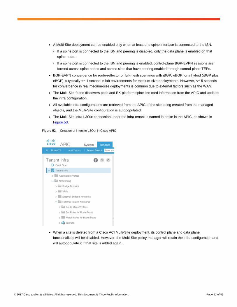
© 2017 Cisco and/or its affiliates. All rights reserved. This document is Cisco Public Information. Page 51 of 53
● A Multi-Site deployment can be enabled only when at least one spine interface is connected to the ISN.
◦ If a spine port is connected to the ISN and peering is disabled, only the data plane is enabled on that
spine node.
◦ If a spine port is connected to the ISN and peering is enabled, control-plane BGP-EVPN sessions are
formed across spine nodes and across sites that have peering enabled through control-plane TEPs.
● BGP-EVPN convergence for route-reflector or full-mesh scenarios with iBGP, eBGP, or a hybrid (iBGP plus
eBGP) is typically <= 1 second in lab environments for medium-size deployments. However, <= 5 seconds
for convergence in real medium-size deployments is common due to external factors such as the WAN.
● The Multi-Site fabric discovers pods and EX-platform spine line card information from the APIC and updates
the infra configuration.
● All available infra configurations are retrieved from the APIC of the site being created from the managed
objects, and the Multi-Site configuration is autopopulated.
● The Multi-Site infra L3Out connection under the infra tenant is named intersite in the APIC, as shown in
Figure 53.
Figure 52. Creation of intersite L3Out in Cisco APIC
● When a site is deleted from a Cisco ACI Multi-Site deployment, its control plane and data plane
functionalities will be disabled. However, the Multi-Site policy manager will retain the infra configuration and
will autopopulate it if that site is added again.
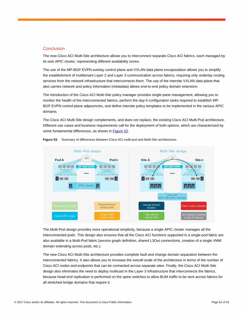
© 2017 Cisco and/or its affiliates. All rights reserved. This document is Cisco Public Information. Page 52 of 53
Conclusion
The new Cisco ACI Multi-Site architecture allows you to interconnect separate Cisco ACI fabrics, each managed by
its own APIC cluster, representing different availability zones.
The use of the MP-BGP EVPN overlay control plane and VXLAN data plane encapsulation allows you to simplify
the establishment of multitenant Layer 2 and Layer 3 communication across fabrics, requiring only underlay routing
services from the network infrastructure that interconnects them. The use of the intersite VXLAN data plane that
also carries network and policy information (metadata) allows end-to-end policy domain extension.
The introduction of the Cisco ACI Multi-Site policy manager provides single-pane management, allowing you to
monitor the health of the interconnected fabrics, perform the day-0 configuration tasks required to establish MP-
BGP EVPN control-plane adjacencies, and define intersite policy templates to be implemented in the various APIC
domains.
The Cisco ACI Multi-Site design complements, and does not replace, the existing Cisco ACI Multi-Pod architecture.
Different use cases and business requirements call for the deployment of both options, which are characterized by
some fundamental differences, as shown in Figure 53.
Figure 53. Summary of differences between Cisco ACI multi-pod and Multi-Site architectures
The Multi-Pod design provides more operational simplicity, because a single APIC cluster manages all the
interconnected pods. This design also ensures that all the Cisco ACI functions supported in a single-pod fabric are
also available in a Multi-Pod fabric (service graph definition, shared L3Out connections, creation of a single VMM
domain extending across pods, etc.).
The new Cisco ACI Multi-Site architecture provides complete fault and change domain separation between the
interconnected fabrics. It also allows you to increase the overall scale of the architecture in terms of the number of
Cisco ACI nodes and endpoints that can be connected across separate sites. Finally, the Cisco ACI Multi-Site
design also eliminates the need to deploy multicast in the Layer 3 infrastructure that interconnects the fabrics,
because head-end replication is performed on the spine switches to allow BUM traffic to be sent across fabrics for
all stretched bridge domains that require it.
© 2017 Cisco and/or its affiliates. All rights reserved. This document is Cisco Public Information. Page 53 of 53
For more information
For more information about the Cisco ACI Multi-Site architecture, refer to the documentation available at the
following link: https://www.cisco.com/c/en/us/support/cloud-systems-management/application-policy-infrastructure-
controller-apic/tsd-products-support-series-home.html.
For a specific example of how to model an application using the Cisco ACI Multi-Site policy manager, refer to the
following document: https://www.cisco.com/c/dam/en/us/solutions/collateral/data-center-virtualization/application-
centric-infrastructure/white-paper-c11-739481.pdf.
A Video on Demand (VoD) of the Cisco ACI Multi-Site breakout session presented at Cisco Live Las Vegas 2017
(BRKACI-2025) is available at the following link:
https://www.ciscolive.com/online/connect/sessionDetail.ww?SESSION_ID=95450&backBtn=true.
Printed in USA C11-739609-00 10/17