Embed Size (px)
Citation preview

C H A P T E R 1
Cisco 8510 Wireless Controller Installation GuideAbout this GuideThis guide is designed to help you install and minimally configure your Cisco 8510 Wireless Controller. This document applies to the following products:
• AIR-CT8510-K9 - the AC version of the Cisco 8510 Wireless Controller
• AIR-CT85DC-K9 - the DC version of the Cisco 8510 Wireless Controller
After installation and power up is complete, refer to the following documents for additional information:
• For information about Wireless LAN Controller software, see http://www.cisco.com/c/en/us/support/wireless/wireless-lan-controller-software/tsd-products-support-series-home.html.
• For information about Cisco 8500 Series Wireless LAN Controller, see http://www.cisco.com/c/en/us/support/wireless/8500-series-wireless-controllers/tsd-products-support-series-home.html
Cisco 8510 Wireless ControllerThe Cisco 8510 Wireless Controller is a highly scalable and flexible platform that enables mission-critical wireless networking in large-scale service provider and large-campus deployments.
The Cisco 8510 Wireless Controller can manage wireless access points in up to 6,000 branch locations and allows IT managers to configure, manage, and troubleshoot up to 6,000 access points and 64,000 clients from the data center. The Cisco 8510 Wireless Controller supports secure guest access, rogue detection for Payment Card Industry (PCI) compliance and in-branch (locally switched) Wi-Fi voice and video.
The Cisco 8510 Wireless Controller can manage Centralized (local mode), FlexConnect mode, and mesh deployments in a single controller.
This Installation Guide contains information and instructions for setting up your Cisco 8510 Wireless Controller and instructions for cabling and configuring the controller. For diagnostics and troubleshooting information, see diagnostics and troubleshooting tables, Table 1-1 on page 1-21 and Table 1-2 on page 1-26.
1-1Cisco 8510 Wireless Controller Installation Guide

Chapter 1 Cisco 8510 Wireless Controller Installation Guide What is in the Cisco 8510 Wireless Controller
Note The Cisco 8510 Wireless Controller is available in two versions: the standard AC version with the PID [AIR-CT8510-K9] and the new DC version with the PID [AIR-CT85DC-K9]. The only difference between these two offerings is the power supply shipped with the product.
Figure 1-1 Cisco 8510 Wireless Controller
Note The power supply, fan, and temperature status are periodically polled from the Cisco WLC software in the intervals of 600 seconds (10 minutes). Therefore, any change in the status of power supply, fan, or temperature can take up to 600 seconds to be reflected.
What is in the Cisco 8510 Wireless ControllerThe following sections describe the features and technologies used by the Cisco 8510 Wireless Controller.
Integrated Management Module The Integrated Management Module (IMM) combines service processor functions. The IMM provides advanced service-processor control, monitoring, and alerting function. If an environmental condition exceeds a threshold or if a system component fails, the IMM lights LEDs to help you diagnose the problem, records the error in the event log, and alerts you to the problem. The IMM provides remote server management through the following industry-standard interfaces:
• Simple Network Management Protocol (SNMP) version 3
• Web browser
For additional information, see the Integrated Management Module User Guide.
Video connector
USB 1connector
Operatorinformationpanel
Drive bay 0 Drive bay 2(Not used)
Drive bay 1 Drive bay 3(Not used)
Rackrelease latch
Rackrelease latch
Hard disk drive activity LED (green)
Hard disk drive status LED (amber)
Optical driveeject button
Optical driveactivity LED
Power-controlbutton and LED
Operator informationpanel release latch
USB 2connector
Opticaldrive bay
2822
99
1-2Cisco 8510 Wireless Controller Installation Guide

Chapter 1 Cisco 8510 Wireless Controller Installation Guide Compliance and Safety Information
Light path diagnostics Light path diagnostics provides LEDs to help you diagnose problems. For more information about the light path diagnostics, see Light Path Diagnostics Panel, page 1-19.
Compliance and Safety Information
FCC Safety Compliance StatementModifying the equipment without Cisco’s authorization may result in the equipment no longer complying with FCC requirements for Class A digital devices. In that event, your right to use the equipment may be limited by FCC regulations, and you may be required to correct any interference to radio or television communications at your own expense.
This equipment has been tested and found to comply with the limits for a Class A digital device, pursuant to Part 15 of the FCC Rules. These limits are designed to provide reasonable protection against harmful interference when the equipment is operated in a commercial environment. This equipment generates, uses, and can radiate radio frequency energy and, if not installed and used in accordance with the instruction manual, may cause harmful interference to radio communications. Operation of this equipment in a residential area is likely to cause harmful interference in which case users will be required to correct the interference at their own expense.
Try to correct the interference by one or more of the following measures:
• Verify that the ambient temperature remains between 50 to 95° F (10 to 35° C), taking into account the elevated temperatures when installed in a rack or enclosed space.
• When multiple Cisco 8510 Wireless Controller are mounted in an equipment rack, be sure that the power source is sufficiently rated to safely run all the equipment in the rack.
• Verify the integrity of the electrical ground before installing the controller.
General Warnings, Regulatory and Safety
ConventionsSafety warnings appear throughout this guide in procedures that may harm you if performed incorrectly. A warning symbol precedes each warning statement. Specific warnings are included in the sections to which they apply.
Warning This warning symbol means danger. You are in a situation that could cause bodily injury. Before you work on any equipment, be aware of the hazards involved with electrical circuitry and be familiar with standard practices for preventing accidents. Use the statement number provided at the end of each warning to locate its translation in the translated safety warnings that accompanied this device. Statement 1071 SAVE THESE INSTRUCTIONS
1-3Cisco 8510 Wireless Controller Installation Guide

Chapter 1 Cisco 8510 Wireless Controller Installation Guide Required Tools and Information
Caution Means reader be careful. In this situation, you might do something that could result in equipment damage or loss of data.
WarningsThe warnings below are general warnings that are applicable to the entire guide. Specific warnings are included in the sections to which they apply.
Warning There is the danger of explosion if the battery is replaced incorrectly. Replace the battery only with the same or equivalent type recommended by the manufacturer. Dispose of used batteries according to the manufacturer’s instructions. Statement 1015
Warning Read the installation instructions before connecting the system to the power source. Statement 1004
Warning Only trained and qualified personnel should be allowed to install, replace, or service this equipment. Statement 1030
Warning Ultimate disposal of this product should be handled according to all national laws and regulations. Statement 1040
Warning Class 1 laser product. Statement 1008
Required Tools and InformationThis section lists the required hardware and other information that you need to install and setup the controller.
Required HardwareYou need the following equipment to install a Cisco 8510 Wireless Controller in an Electronics Industries Alliance (EIA) rack:
• A Cisco 8510 Wireless Controller
• Network cables
• One rack unit (RU) free space in an EIA-standard rack
• One or two Cisco SFP-10G-SR modules and corresponding optical cables
• Rack mounting kit (included with the Cisco 8510 Wireless Controller shipment)
• A serial console cable
1-4Cisco 8510 Wireless Controller Installation Guide
Chapter 1 Cisco 8510 Wireless Controller Installation Guide Required Tools and Information
For installing AIR-CT85DC-K9, the DC version of the Cisco Series 8500 Wireless Controller, 12 AWG copper cables and appropriate termination connectors are required. See details in Powering On the Controller, page 1-40.
Note If you are installing this unit in a threaded-hole rack, you must supply screws that fit the threaded-hole rack and the appropriate screwdriver or Torx driver for those screws.
CLI Console RequirementsYou need this equipment to connect to the controller console:
• ANSI or VT-100 terminal emulator application on a laptop, desktop, or palmtop
Note Please refer to the latest Release Notes for Cisco 8500 Series Wireless Controller for compatibility by release between the Cisco Prime Infrastructure and controller releases at: http://www.cisco.com/c/en/us/support/wireless/8500-series-wireless-controllers/products-release-notes-list.html
System Configuration ParametersObtain the following initial configuration parameters from your wireless LAN or network administrator:
• A system (controller) name.
• An administrative username and password.
• A service port interface IP address configuration protocol (none or DHCP).
• A management interface (DS port or network interface port) IP address.
Note The service port interface and management interface must be on different subnets.
• A management interface netmask address.
• A management interface default router IP address.
• A VLAN identifier if the management interface is assigned to a VLAN, or 0 for an untagged VLAN.
• Distribution system physical port number—1 through 2 for back panel 10 Gigabit Ethernet ports (with SFP+ 10G module).
• IP address of the default DHCP server that will supply IP addresses to clients.
• A virtual gateway IP address (a fictitious, unassigned IP address, such as 192.0.2.1, used by all Cisco wireless LAN controller Layer 3 security and mobility managers).
• A Cisco wireless LAN controller mobility group name, if required.
• An 802.11 network name (SSID) for WLAN 1. This is the default SSID that the access points use when they join with the controller.
• Whether or not to allow static IP addresses from clients.
– Yes is more convenient, but has lower security (session can be hijacked).
– No is less convenient, but has higher security and works well for Windows XP devices.
1-5Cisco 8510 Wireless Controller Installation Guide

Chapter 1 Cisco 8510 Wireless Controller Installation Guide Choosing a Physical Location for the Cisco 8510 Wireless Controller
• RADIUS server IP address, communications port, and secret (if you are configuring a RADIUS server).
• The country code for this installation. Refer to the Cisco Wireless LAN Controller Configuration Guide for country code information. This guide is available at cisco.com.
• Status of the 802.11a, 802.11b, and 802.11g networks (enabled or disabled).
• Status of radio resource management (RRM) (enabled or disabled).
• An IP address for the Integrated Management Module (IMM), if you are using a static IP address for IMM access. The IMM can use either a shared port with service port or the dedicated IMM Ethernet port.
Choosing a Physical Location for the Cisco 8510 Wireless Controller
For maximum safety and reliability, mount the controller using the following guidelines.
General PrecautionsTo reduce the risk of personal injury or damage to the controller:
• Place the product away from radiators, heat registers, stoves, amplifiers, or other products that produce heat.
• Never use the product in a wet location.
• Avoid inserting foreign objects through openings in the product.
• To reduce risk of injury from electric shock hazards, do not open the product enclosure.
Laser DevicesLaser devices are used within the DVD of the controller. The DVD has no defined use at the customer site.
To reduce the risk of exposure to hazardous radiation:
• Do not try to open the laser device enclosure. There are no user-serviceable components inside.
• Do not operate controls, make adjustments, or perform procedures to the laser device other than those specified herein.
• Allow only Cisco authorized service technicians to repair the laser device.
Space and Airflow RequirementsInstall the controller in a EIA-standard rack. One rack unit is required for each controller.
Ensure that you can reach the controller and all cables.
• Ensure that the controller is within 328 ft (100 m) equivalent distance from any equipment connected to the 10/100/1000BASE-T/10G ports. For specifications on the fiber optic cables, see “Connecting the Network (Distribution System)” section on page 1-47.
1-6Cisco 8510 Wireless Controller Installation Guide

Chapter 1 Cisco 8510 Wireless Controller Installation Guide Choosing a Physical Location for the Cisco 8510 Wireless Controller
• Ensure that the power cord can reach a 110 or 220 VAC grounded electrical outlet.
Ensure that there is sufficient room at the back of the controller for all cables and connectors.
• Leave a minimum clearance of 63.5 cm (25 in.) in front of the rack.
• Leave a minimum clearance of 76.2 cm (30 in.) behind the rack.
• Leave a minimum clearance of 121.9 cm (48 in.) from the back of the rack to the back of another rack or row of racks.
Caution To prevent improper cooling and damage to the equipment, do not block the ventilation openings.
Caution Always use blanking panels to fill empty vertical spaces in the rack. This arrangement ensures proper airflow. Using a rack without blanking panels results in improper cooling that can lead to thermal damage.
Caution When selecting a rack to use, observe the following additional requirements to ensure adequate airflow and to prevent damage to the equipment: (1) Front and rear doors—If the 42U rack includes closing front and rear doors, you must allow 5,350 sq. cm (830 sq. in.) of holes evenly distributed from top to bottom to permit adequate airflow (equivalent to the required 64 percent open area for ventilation). (2) Side—The clearance between the installed rack component and the side panels of the rack must be a minimum of 7 cm (2.75 in.).
Temperature RequirementsTo ensure continued safe and reliable equipment operation, install or position the system in a well ventilated, climate-controlled environment.
Ensure that the ambient operating temperature remains between 10 and 35° C (50 and 95° F), taking into account the elevated temperatures that occur when equipment is installed in a rack.
Caution To reduce the risk of damage to the equipment when installing third-party options: (1) Do not permit optional equipment to impede airflow around the controller or to increase the internal rack temperature beyond the maximum allowable limits. (2) Do not exceed the manufacturer’s maximum recommended ambient temperature (TMRA).
Power RequirementsInstallation of this equipment must comply with local and regional electrical regulations governing the installation of information technology equipment by licensed electricians. This equipment is designed to operate in installations covered by NFPA 70, 1999 Edition (National Electric Code) and NFPA 75, 1992 (code for Protection of Electronic Computer/Data Processing Equipment). For electrical power ratings on options, refer to the product rating label or the user documentation supplied with that option.
1-7Cisco 8510 Wireless Controller Installation Guide

Chapter 1 Cisco 8510 Wireless Controller Installation Guide Choosing a Physical Location for the Cisco 8510 Wireless Controller
Caution Protect the controller from power fluctuations and temporary interruptions with a regulating uninterruptible power supply (UPS). This device protects the hardware from damage caused by power surges and voltage spikes and keeps the system in operation during a power failure.
When installing more than one controller, you may need to use additional power distribution devices (PDUs) to safely provide power to all devices. Observe the following guidelines:
• Balance the controller power load among available AC supply branch circuits.
• If you are using the AC version [AIR-CT8510-K9], do not allow the overall system AC current load to exceed 80 percent of the branch circuit AC current rating.
• Do not use common power outlet strips for this equipment.
• Provide a separate electrical circuit for the controller.
Please follow the instructions in Connecting the DC Version of the 8510 [AIR-CT85DC-K9] to a Power Source, page 1-40 to connect the DC version [AIR-CT85DC-K9] to DC power source.
Power Supplies on the Cisco 8510 Wireless Controller
The Cisco 8510 Wireless Controller has two power supplies.
Warning This unit might have more than one power supply connection. All connections must be removed to de-energize the unit. Statement 1028
Caution Verify that the external power source connected to the controller matches the type of power source indicated on the electrical ratings label. If you are not sure of the type of power source required, consult your Cisco authorized reseller or local power company.
Batteries
The controller might include a real-time clock battery or coin cell battery that might contain perchlorate and might require special handling when recycled or disposed of in California.
Refer to the following link for disposal information.
http://www.dtsc.ca.gov/hazardouswaste/perchlorate
Caution Do not dispose of batteries with the general household waste. Recycle them using the public collection system.
Electrical Grounding RequirementsThe controller must be grounded properly for proper operation and safety. In the United States, you must install the equipment in accordance with NFPA 70, 1999 Edition (National Electric Code), Article 250, as well as any local and regional building codes. In Canada, you must install the equipment in accordance
1-8Cisco 8510 Wireless Controller Installation Guide

Chapter 1 Cisco 8510 Wireless Controller Installation Guide Unpacking the Controller
with Canadian Standards Association, CSA C22.1, Canadian Electrical Code. In all other countries, you must install the equipment in accordance with any regional or national electrical wiring codes, such as the International Electrotechnical Commission (IEC) Code 364, parts 1 through 7.
Furthermore, you must verify that all power distribution devices used in the installation, such as branch wiring and receptacles, are listed or certified grounding-type devices. Because of the high ground-leakage currents associated with multiple systems connected to the same power source, Cisco recommends the use of a PDU that is either permanently wired to the building’s branch circuit or includes a nondetachable cord that is wired to an industrial-style plug. NEMA locking-style plugs or those complying with IEC 60309 are considered suitable for this purpose. Using common power outlet strips for the controller is not recommended.
Rack Warnings
Warning To prevent bodily injury when mounting or servicing this unit in a rack, you must take special precautions to ensure that the system remains stable. The following guidelines are provided to ensure your safety: (1) This unit should be mounted at the bottom of the rack if it is the only unit in the rack. (2) When mounting this unit in a partially filled rack, load the rack from the bottom to the top with the heaviest component at the bottom of the rack. (3) If the rack is provided with stabilizing devices, install the stabilizers before mounting or servicing the unit in the rack. Statement 1006.
Caution To reduce the risk of personal injury or equipment damage when unloading a rack, at least two people are needed to safely unload the rack from the pallet.
Caution To prevent damage, ensure that water or excessive moisture cannot get into the controller.
Unpacking the ControllerFollow these steps to unpack the Cisco 8510 Wireless Controller and prepare it for operation:
Step 1 Open the shipping container and carefully remove the contents.
Step 2 Return all packing materials to the shipping container and save it.
Step 3 Ensure that all items listed in the “Package Contents” section on page 1-9 are included in the shipment.
Step 4 Check each item for damage. If any item is damaged or missing, notify your authorized Cisco sales representative.
Package ContentsEach controller package contains the following items:
• Cisco 8510 Wireless Controller
1-9Cisco 8510 Wireless Controller Installation Guide

Chapter 1 Cisco 8510 Wireless Controller Installation Guide Mounting the Cisco 8510 Wireless Controller in a Rack
• One rack mount kit
• Two power cords (for AIR-CT8510-K9 only)
• One console cable for 10 Gb SFP+ card
• Regulatory Compliance and Safety Information for the Cisco 8510 Wireless Controller
• Cisco product registration and Cisco documentation feedback cards
Mounting the Cisco 8510 Wireless Controller in a Rack
Warning Only trained and qualified personnel should be allowed to install, replace, or service this equipment. Statement 1030
Caution The controller is heavy (35 lbs, 15.9 kgs).
To reduce the risk of personal injury or damage to the equipment:
• Observe local occupational health and safety requirements and guidelines for manual material handling.
• Get help to lift and stabilize the controller during installation or removal is recommended, especially when the system is not fastened to the rails.
• Use caution when installing the controller in or removing it from the rack; it is unstable when not fastened to the rails.
• Always plan the rack installation so that the heaviest item is on the bottom of the rack. Install the heaviest item first and continue to populate the rack from the bottom to the top.
The controller comes with a universal rack mount kit that can be installed in a square-hole rack, round-hole rack, or a threaded-hole rack. You can order replacement universal rack mount kits from Cisco. The replacement part PID is AIR-SRVR-URMK=.
Note You must provide the threaded-hole screws to secure the mounting rails to the rack. Threaded-hole screws are not shipped with the system.
Installing the Controller Into the Rack Cabinet Using Universal Rack Mount KitReview the documentation that comes with the rack cabinet for safety and cabling information. Before you install the controller in a rack cabinet, review the following guidelines:
• Two or more people are required to install this device in a rack cabinet.
• Make sure that the room air temperature is below 35° C (95° F).
• Do not block any air vents; usually 15 cm (6 in.) of space provides proper airflow.
• Do not leave open spaces above or below an installed controller in your rack cabinet. To help prevent damage to controller components, always install a blank filler panel to cover the open space and to help ensure proper air circulation.
• Install the controller only in a rack cabinet with perforated doors.
1-10Cisco 8510 Wireless Controller Installation Guide

Chapter 1 Cisco 8510 Wireless Controller Installation Guide Mounting the Cisco 8510 Wireless Controller in a Rack
• Plan the device installation starting from the bottom of the rack cabinet.
• Install the heaviest device in the bottom of the rack cabinet.
• Do not extend more than one device out of the rack cabinet at the same time.
• Remove the rack doors and side panels to provide easier access during installation.
• Connect the controller to a properly grounded outlet.
• Do not overload the power outlet when you install multiple devices in the rack cabinet.
• Install the controller in a rack that meets the following requirement:
– Minimum depth of 70 mm (2.76 in.) between the front mounting flange and inside of the front door.
Caution Use safe practices when lifting.
Caution Do not place any object on top of rack-mounted devices.
The following illustration shows the items that you need to install the controller in the rack cabinet. If any items are missing or damaged, contact your place of purchase.
Note Some items come with the controller, not in the rack installation kit.
1-11Cisco 8510 Wireless Controller Installation Guide

Chapter 1 Cisco 8510 Wireless Controller Installation Guide Mounting the Cisco 8510 Wireless Controller in a Rack
Note Use cage bars with square-holed racks, clip nuts with round-holed racks, and your own screws or the screws provided in this kit with threaded-hole racks.
Note If the slide rails in your rack installation kit came with shipping thumbscrews, remove them before you begin the following installation procedure.
Step 1 Select an available 1U space in your rack to install your controller. If you have either a round-holed or square-holed rack, install cage bars or clip nuts in the middle and the bottom (optional for the upper) holes of the lower U on each side of the front of the rack. Then, install cage bars or clip nuts in the upper and the bottom holes of the lower U on each side of the rear of the rack.
M6 screws(12)
Cage bars(4)
Slide rail(right)
Slide rail(left)
Front of rails10-32 screws
(13)12-24 screws
(13)
EIA latches(2)
Clip nuts(13)
2551
72
1-12Cisco 8510 Wireless Controller Installation Guide

Chapter 1 Cisco 8510 Wireless Controller Installation Guide Mounting the Cisco 8510 Wireless Controller in a Rack
Step 2 Use a screwdriver to install the cage bars or the clip nuts on the inside of the mounting rail, as required for your rack, into the selected holes.
Step 3 The rail depth can be adjusted from 17 in (432 mm) to 31.25 in (794 mm). To adjust the depth, you can loosen the nuts on the posts and slide the bracket until the distance between the front and rear slide rail flanges matches the distance between the front and rear EIA rails of the rack cabinet. If you need further adjustment, remove the nuts, move the bracket to the appropriate set of posts (A, B, C, and D) to obtain the appropriate slide rail depth, then reinstall and tighten the nuts.
Front Rear
Upper U(For 2 Usystem)
Lower U
Clip orcage nuts
Optional screwto secure system
into the rack
2551
56
Cagebars
Front Rear
Clipnuts
Front Rear
2551
57
1-13Cisco 8510 Wireless Controller Installation Guide

Chapter 1 Cisco 8510 Wireless Controller Installation Guide Mounting the Cisco 8510 Wireless Controller in a Rack
Step 4 To remove the support bracket, remove the screw (1) and remove the bracket (2) from the rear of the slide rail.
Step 5 To remove the mounting brackets, remove the screws (1) and (3). Slide out the brackets (2) and (4) from the rear of the slide rail.
Slots
Post A
Post B
Post C
Post D
2551
5825
5160
1
225
5161
1
23
4
1-14Cisco 8510 Wireless Controller Installation Guide

Chapter 1 Cisco 8510 Wireless Controller Installation Guide Mounting the Cisco 8510 Wireless Controller in a Rack
Step 6 Attach the front of the slide rail and EIA latch to the front of the rack cabinet by installing a screw in the bottom hole of the lower U; then, install another screw in the middle hole of the lower U to attach the front of the slide rail to the front of the rack cabinet.
Note When you fasten the slides to the rack, ensure the screws are engaged but the flange can move slightly. You will use a screwdriver to fully tighten them in Step 9.
Note Use 12-24 screws (not hex head M6 screws) on the front mounting bracket if you are installing this system into a rack with round or square holes (i.e., not threaded holes).
Step 7 Use two screws to attach the rear of the slide rail to the rear of the rack cabinet in the upper and the bottom holes of the lower U.
Repeat Step 3 through Step 7 to install the other slide rail into the rack.
Cap headM6 screw
2551
70
Hex head M6 screw
2551
71
1-15Cisco 8510 Wireless Controller Installation Guide

Chapter 1 Cisco 8510 Wireless Controller Installation Guide Mounting the Cisco 8510 Wireless Controller in a Rack
Step 8 Pull the slide rails forward (1) until they click, two times, into place. Carefully lift the controller and tilt it into position over the slide rails so that the rear nail heads (2) on the controller line up with the rear slots (3) on the slide rails. Slide the controller down until the rear nail heads slip into the two rear slots, and then slowly lower the front of the controller (4) until the other nail heads slip into the other slots on the slide rails. Make sure that the front latch (5) slides over the nail heads.
Step 9 Lift the locking levers (1) on the slide rails and push the controller (2) all the way into the rack until it clicks into place.
Slide the system in and out twice to make sure the system slides correctly. Push the system inwards to the rack as close as possible but able to access the screws with a screwdriver. Then tighten the screws with a screwdriver.
Step 10 Slide the controller into the rack until it snaps into place. To slide the controller out of the rack, press on the release latches (1).
Note When you move the rack cabinet, or if you install the rack cabinet in a vibration-prone area, insert the optional M6 screws (2) in the front of the controller.
2551
62
1
2
34
5
2551
63
1
2
1-16Cisco 8510 Wireless Controller Installation Guide

Chapter 1 Cisco 8510 Wireless Controller Installation Guide Front Panel
To remove the controller from the rack, reverse these instructions. Store this information with your controller documentation for future use.
Front PanelFigure 1-2 shows the controls, Light Emitting Diodes (LEDs), and connectors on the front panel of the Cisco 8510 Wireless Controller.
Figure 1-3 shows a detailed view of the operator information panel.
Figure 1-2 Cisco 8510 Wireless Controller Front Panel
Front Panel Components• Rack release latches: Press the latches on each front side of the controller to remove it from the
rack.
1
2
2551
69
Video connector
USB 1connector
Operatorinformationpanel
Drive bay 0 Drive bay 2(Not used)
Drive bay 1 Drive bay 3(Not used)
Rackrelease latch
Rackrelease latch
Hard disk drive activity LED (green)
Hard disk drive status LED (amber)
Optical driveeject button
Optical driveactivity LED
Power-controlbutton and LED
Operator informationpanel release latch
USB 2connector
Opticaldrive bay
2822
99
1-17Cisco 8510 Wireless Controller Installation Guide

Chapter 1 Cisco 8510 Wireless Controller Installation Guide Front Panel
• Hard disk drive status LEDs: This LED is used to indicate the status of the SAS hard disk drives. When this LED is lit, it indicates that the drive has failed. When this LED is flashing slowly (one flash per second), it indicates that the drive is being rebuilt. When the LED is flashing rapidly (three flashes per second), it indicates that the controller is identifying the drive.
• Hard disk drive activity LEDs: Each hot-swap hard disk drive has an activity LED, and when this LED is flashing, it indicates that the drive is in use.
• Optical drive eject button: Press this button to release a DVD or CD from the DVD drive.
• Optical drive activity LED: When this LED is lit, it indicates that the DVD drive is in use.
• Operator information panel: This panel contains controls and LEDs that provide information about the status of the controller. For information about the controls and LEDs on the operator information panel, see Operator Information Panel, page 1-18.
• Operator information panel release latch: Slide the blue release latch to the left to pull out the light path diagnostics panel and view the light path diagnostics LEDs and buttons. See Light Path Diagnostics Panel, page 1-19 for more information about the light path diagnostics.
• Video connector: Connect a monitor to this connector. The video connectors on the front and rear of the controller can be used simultaneously. Controller configuration and management is only supported via the serial console connection. Controller configuration and management is not supported using the keyboard and monitor directly connected to the controller.
Note The maximum video resolution is 1600 x 1200 at 75 Hz.
• USB connectors: Connect a USB device, such as a USB mouse or keyboard, to any of these connectors. During normal operation, this USB slot is not used by the Cisco 8510 Wireless Controller.
Operator Information Panel Figure 1-3 shows a detailed view of the controls and LEDs on the operator information panel.
Figure 1-3 Close Up of Cisco 8510 Wireless Controller Operator Information Panel
21
43
Ethernet activity LEDs
Locator button/locator LED
Information LED
System-error LED
Release latchPower-control button/power-on LED
Ethernet activity LEDs
Power-controlbutton cover
Ethernet icon LED
2551
26
1-18Cisco 8510 Wireless Controller Installation Guide

Chapter 1 Cisco 8510 Wireless Controller Installation Guide Front Panel
Operator Information Panel Components
• Power-control button and power-on LED: Press this button to turn the controller on and off manually or to wake it from a reduced-power state. The states of the power-on LED are as follows:
– Off: Power is not present, or the power supply or the LED itself has failed.
– Flashing rapidly (4 times per second): The controller is turned off and is not ready to be turned on. The power-control button is disabled. This will last approximately 20 to 40 seconds.
– Flashing slowly (once per second): The controller is turned off and is ready to be turned on. You can press the power-control button to turn on the controller.
– Lit: The controller is turned on.
– Fading on and off: The controller is in a reduced-power state. To wake the controller, press the power-control button or use the IMM Web interface. See the Integrated Management Module User’s Guide for information on logging on to the IMM Web interface.
• Ethernet activity LEDs: When any of these LEDs is lit, they indicate that the controller is transmitting to or receiving signals from the Ethernet LAN that is connected to the Ethernet port that corresponds to that LED.
• System-locator button/LED: Use this blue LED to visually locate the controller among other servers. This LED is also used as a presence detection button. This LED is controlled by the IMM. When you press the System-locator button, the LED will blink and it will continue to blink until you press it again to turn it off. The locator button is pressed to visually locate the controller among the other servers.
• System-information LED: When this amber LED is lit, it indicates that a noncritical event has occurred. The IMM can be used to diagnose and correct the problem.
• System-error LED: When this amber LED is lit, it indicates that a system error has occurred. A system-error LED is also on the rear of the controller. An LED on the light path diagnostics panel on the operator information panel is also lit to help isolate the error. This LED is controlled by the IMM.
Light Path Diagnostics Panel The light path diagnostics panel is on the top of the operator information panel, as shown in Figure 1-4. For additional information about the LEDs on the light path diagnostics panel, see Table 1-1.
To access the light path diagnostics panel, slide the blue release button on the operator information panel to the left. Pull forward on the unit until the hinge of the operator panel is free of the chassis. Then pull down on the unit, so that you can view the light path diagnostics panel information.
Note When you slide the light path diagnostics panel out of the controller to check the LEDs or checkpoint codes, do not run the controller continuously with the light path diagnostics panel outside of the controller. The panel should only be outside of the controller a short time. The light path diagnostics panel must remain in the controller when it is running to ensure proper cooling.
1-19Cisco 8510 Wireless Controller Installation Guide

Chapter 1 Cisco 8510 Wireless Controller Installation Guide Front Panel
Figure 1-4 Light Path Diagnostics Panel
Figure 1-5 shows the LEDs and controls on the light path diagnostics panel.
Figure 1-5 Light Path Diagnostics Panel Components
Light Path Diagnostics Panel Components
• Remind button: This button places the system-error LED on the front panel into Remind mode. In Remind mode, the system-error LED flashes once every 2 seconds until the problem is corrected, the controller is restarted, or a new problem occurs.
By placing the system-error LED indicator in Remind mode, you acknowledge that you are aware of the last failure but will not take immediate action to correct the problem. The Remind function is controlled by the IMM.
Operator informationpanel
Light pathdiagnostics LEDs
Release latch
2551
27
Light Path Diagnostics
OVERSPEC LOG LINK PS PCI SP
FAN TEMP MEM NMI
REMIND
CPU VRM DASD RAID BRDCNFG
RESET
Checkpoint code
NMI button
2551
34
1-20Cisco 8510 Wireless Controller Installation Guide

Chapter 1 Cisco 8510 Wireless Controller Installation Guide Front Panel
• NMI button: This button is used to force a nonmaskable interrupt to the microprocessor. This button is not currently used by the Cisco 8510 Wireless Controller. Press this button only when directed by the Cisco TAC personnel.
• Checkpoint code display: This display provides a checkpoint code that indicates the point at which the system stopped during the boot block and POST. A checkpoint code is either a byte or a word value that is produced by UEFI. The display does not provide error codes or suggest components to be replaced.
• Reset button: Press this button to reset the controller and run the power-on self-test (POST). You might have to use a pen or the end of a straightened paper clip to press the button. The Reset button is in the lower-right corner of the light path diagnostics panel.
Table 1-1 Light path diagnostics panel LEDs
Follow the suggested actions in the order in which they are listed in the Action column until the problem is solved.
LED Description Action
None, but the system error LED is lit.
An error occurred and cannot be isolated. The error is not represented by a path.
Contact Cisco TAC for assistance.
OVER SPEC The power supplies are using more power than their maximum rating.
Contact Cisco TAC for assistance.
LOG An error occurred. Check the IMM system event log and the system-error log for information about the error and then determine the next steps. If needed, contact Cisco TAC.
LINK Reserved.
PS Power supply 1 or 2 has failed. 1. Check the power supply that has a lit amber LED (see Power-supply LEDs, page 1-26).
2. Make sure that the power supplies are seated correctly.
3. Remove one of the power supplies to isolate the failed power supply.
4. Replace the failed power supply.
PCI An error has occurred on a PCI bus or on the system board. An additional LED is lit next to a failing PCI slot.
Contact Cisco TAC for assistance.
SP A service processor error has been detected.
1. Shut down the system and remove the power cords from the controller; then, reconnect the controller to power and restart it.
2. If the problem does not go away, contact Cisco TAC for assistance.
1-21Cisco 8510 Wireless Controller Installation Guide

Chapter 1 Cisco 8510 Wireless Controller Installation Guide Front Panel
FAN A fan has failed, is operating too slowly, or has been removed. The TEMP LED might also be lit.
Contact Cisco TAC to replace your Cisco 8510 Wireless Controller and for further assistance.
TEMP The system temperature has exceeded a threshold level. A failing fan can cause the TEMP LED to be lit.
Contact Cisco TAC for assistance.
MEM When only the MEM LED is lit, a memory error has occurred. When both the MEM and CNFG LEDs are lit, the memory configuration is invalid or the PCI Option ROM is out of resource.
Contact Cisco TAC for assistance.
NMI A nonmaskable interrupt has occurred, or the NMI button was pressed.
Check the system-error log for information about the error.
Contact Cisco TAC if further assistance is needed.
CNFG A hardware configuration error has occurred.
Contact Cisco TAC for assistance.
CPU An invalid microprocessor configuration or a microprocessor has failed (both the CPU LED and the CNFG LED might be lit).
Contact Cisco TAC for assistance.
VRM Reserved.
DASD A hard disk drive has failed or is missing.
1. Check the LEDs on the hard disk drives for the drive with a lit status LED and reseat the hard disk drive.
2. If reseating the drive does not resolve the issue, then the failed hard disk drive must be replaced. Contact Cisco TAC for assistance.
RAID Reserved.
BRD An error has occurred on the system board.
Contact Cisco TAC for assistance.
Table 1-1 Light path diagnostics panel LEDs (continued)
Follow the suggested actions in the order in which they are listed in the Action column until the problem is solved.
LED Description Action
1-22Cisco 8510 Wireless Controller Installation Guide

Chapter 1 Cisco 8510 Wireless Controller Installation Guide Rear Panel
Rear PanelFigure 1-6 shows the connectors on the rear panel for the Cisco 8510 Wireless Controller.
Figure 1-7 shows the Cisco 8510 Wireless Controller rear panel LEDs.
Figure 1-6 Cisco 8510 Wireless Controller Rear Panel
Rear Panel Components• 10G ports: Use these connectors to connect the controller to a network. The 10G connectors provide
interface for 10 Gb SFP+ transceivers. When you use the Service Port connector, the network can be shared with the IMM through a single network cable. See additional notes about the IMM configuration and access for details.
• Power connector: Connect the power cord to this connector.
Note Power supply 1 is the default/primary power supply. If power supply 1 fails, you must replace it immediately.
Note The DC-powered 8510 controller does not ship with any of the country-specific power cords. For these DC-powered units, use 12G wires (customer-supplied) and connect to the DC power supply.
• Video connector: Connect a monitor to this connector. The video connectors on the front and rear of the controller can be used simultaneously.
Note The maximum video resolution is 1600 x 1200 at 75 Hz.
• Serial connector: Connect the serial console cable to this connector.
AC
DC
AC
DC
IMM 10/100 Mbps Ethernet port
HA port
Video connector
Serialconnector
USB 3connector
USB 5connector(Not used)
Power cordconnectors
Powersupply 1
Powersupply 210G port 1 10G port 2
USB 4connector
Console port(Not used)
Service port
28
23
00
1-23Cisco 8510 Wireless Controller Installation Guide

Chapter 1 Cisco 8510 Wireless Controller Installation Guide Rear Panel
• USB connectors: Connect a USB device, such as a USB mouse or keyboard to any of these connectors. During normal operation, these USB slots are not used by the Cisco 8510 Wireless Controller.
• Console port: This console port is not intended for customer use. It is used by Cisco TAC for debugging purposes. Do not discard the console cable that comes with your controller.
• IMM 10/100 Mbps Ethernet port: Use this port to manage the controller, using a dedicated management network. If you use this connector, the IMM cannot be accessed directly from production network. A dedicated management network provides additional security by physically separating the management network traffic from the production network. You can use the immconfig script provided with the controller to configure it to use a dedicated systems management network or a shared network.
Figure 1-7 shows the LEDs on the rear of the controller.
Figure 1-7 Cisco 8510 Wireless Controller Rear Panel LEDs
2823
01
AC
DC
AC
DC
Ethernetactivity LED
Ethernetlink LED
Power LED(green)
System-locatorLED (blue)
System-errorLED (amber)
AC LED (green)DC LED (green)Power-supplyerror LED (amber)
10G link statusLEDs
1-24Cisco 8510 Wireless Controller Installation Guide

Chapter 1 Cisco 8510 Wireless Controller Installation Guide Rear Panel
Figure 1-8 shows a detailed view of the LEDs on a DC power supply. This image applies to the AIR-CT85DC-K9 model only.
Figure 1-8 Cisco 8510 Wireless Controller DC Power Supply LEDs (AIR-CT85DC-K9)
• Ethernet activity LEDs: When these LEDs are lit, they indicate that the controller is transmitting to or receiving signals from the Ethernet LAN that is connected to the Ethernet port.
• Ethernet link LEDs: When these LEDs are lit, they indicate that there is an active link connection on the 10BASE-T, 100BASE-TX, or 1000BASE-TX interface for the Ethernet port.
• AC power LED: Each hot-swap power supply has an AC power LED and a DC power LED. When the AC power LED is lit, it indicates that sufficient power is coming into the power supply through the power cord. During typical operation, both the AC and DC power LEDs are lit.
• IN OK power LED: Each hot-swap DC power supply has an IN OK power LED and an OUT OK power LED. When the IN OK power LED is lit, it indicates that sufficient power is coming into the power supply through the power cord. During typical operation, both the IN OK and OUT OK power LEDs are lit.
• DC power LED: Each hot-swap power supply has a DC power LED and an AC power LED. When the DC power LED is lit, it indicates that the power supply is supplying adequate DC power to the system. During typical operation, both the AC and DC power LEDs are lit.
• OUT OK power LED: Each hot-swap DC power supply has an IN OK power LED and an OUT OK power LED. When the OUT OK power LED is lit, it indicates that the power supply is supplying adequate DC power to the system. During typical operation, both the IN OK and OUT OK power LEDs are lit.
• 10 G link status LEDs: These LEDs individually indicate the transmit and receive activity of each 10 Gb SFP+ transceiver.
• System-error LED: When this LED is lit, it indicates that a system error has occurred. An LED on the light path diagnostics panel is also lit to help isolate the error.
• Power-on LED: When this LED is lit and not flashing, it indicates that the controller is turned on. The states of the power-on LED are as follows:
– Off: Power is not present, or the power supply or the LED itself has failed.
– Flashing rapidly (4 times per second): The controller is turned off and is not ready to be turned on. The power-control button is disabled. This will last approximately 20 to 40 seconds.
-48V returnGround-48V
Power input LED
Power output LED
Power error LED
2551
33
1-25Cisco 8510 Wireless Controller Installation Guide

Chapter 1 Cisco 8510 Wireless Controller Installation Guide Rear Panel
– Flashing slowly (once per second): The controller is turned off and is ready to be turned on. You can press the power-control button to turn on the controller.
– Lit: The controller is turned on.
– Fading on and off: The controller is in a reduced-power state. To wake the controller, press the power-control button or use the IMM Web interface. See the Integrated Management Module User’s Guide for information on logging on to the IMM Web interface.
• System-locator LED: Use this LED to visually locate the controller among other servers. You can use the Integrated Management Module User’s Guide to light this LED remotely.
Power-supply LEDs
Figure 1-9 shows the location of the power-supply LEDs on the rear of the Cisco 8510 Wireless Controller. See Table 1-2 and Table 1-3 for additional information about solving power supply problems.
Figure 1-9 Location of the Cisco 8510 Wireless Controller Power Supply LEDs
Table 1-2 describes the problems that are indicated by various combinations of the power-supply LEDs on an AC power supply and suggested actions to correct the detected problems.
AC
DC
AC
DC
AC LED (green)
DC LED (green)
Power-supplyerror LED (amber)
2823
02
Table 1-2 Cisco 8510 Wireless Controller AC Power Supply Troubleshooting
AC power-supply LEDs
Description Action NotesAC DC Error (!)
On On Off Normal operation
Off Off Off No AC power to the controller or a problem with the AC power source.
1. Check the AP power to the controller.
2. Make sure that the power cord is connected to a functioning power source.
3. Restart the controller. If the error remains, check the power supply LEDs.
4. Replace the power supply.
This is a normal condition when no AC power is present.
1-26Cisco 8510 Wireless Controller Installation Guide
Chapter 1 Cisco 8510 Wireless Controller Installation Guide Rear Panel
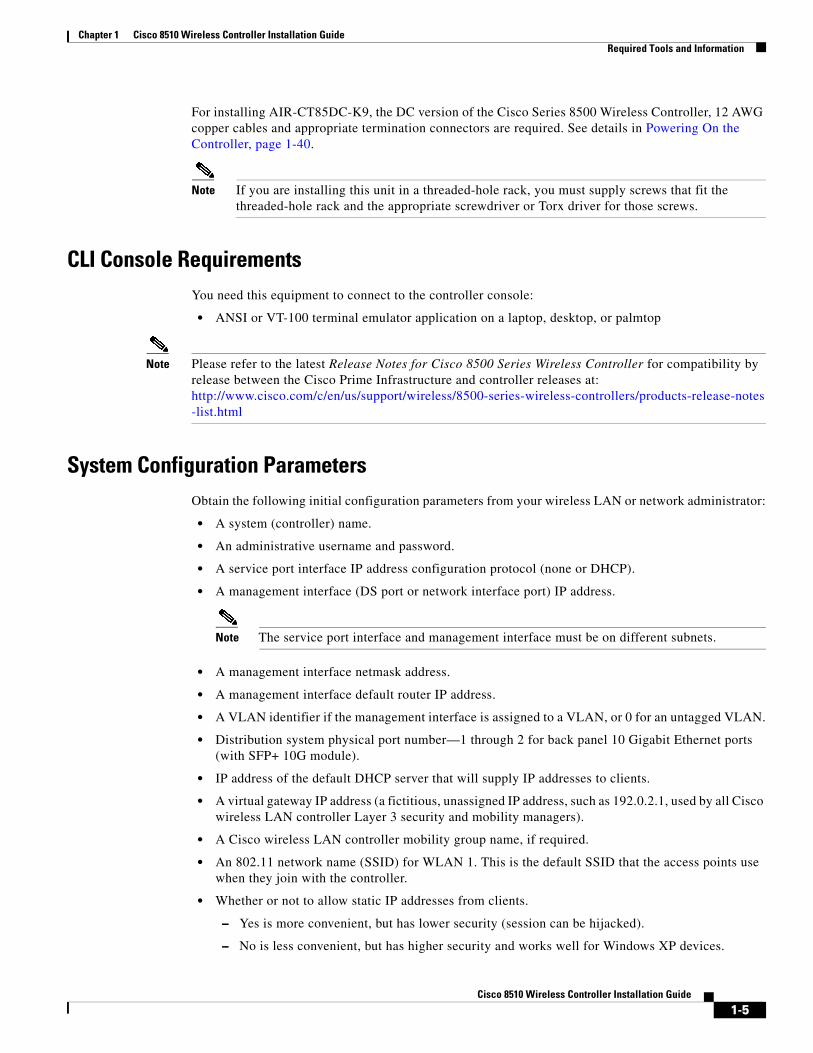
Table 1-3 describes the problems that are indicated by various combinations of the power-supply LEDs on a DC power supply and suggested actions to correct the detected problems. This table applies to the AIR-CT85DC-K9 model only.
Off Off On No AC power to the controller or a problem with the AC power source and the power supply had detected an internal problem.
1. Make sure that the power cord is connected to a functioning power source.
2. Replace the power supply.
This happens only when a second power supply is providing power to the controller.
Off On Off Faulty power supply
Replace the power supply.
Off On On Faulty power supply
Replace the power supply.
On Off Off Power supply not fully seated, faulty system board, or faulty power supply
1. Reseat the power supply.
2. If this action does not resolve the problem, replace the power supply. If replacing the power supply does not resolve the issue, contact Cisco TAC for assistance.
Typically indicates a power supply is not fully seated.
On Off On Faulty power supply
Replace the power supply.
On On On Power supply is faulty but still operational
Replace the power supply.
Table 1-2 Cisco 8510 Wireless Controller AC Power Supply Troubleshooting (continued)
AC power-supply LEDs
Description Action NotesAC DC Error (!)
Table 1-3 Cisco 8510 Wireless Controller DC Power Supply Troubleshooting (AIR-CT85DC-K9)
DC power-supply LEDs
Description Action NotesIN OK OUT OK Error (!)
On On Off Normal operation
Off Off Off No DC power to the controller or a problem with the DC power source.
1. Check the DC power to the controller.
2. Make sure that the power cord is connected to a functioning power source.
3. Restart the controller. If the error remains, check the power supply LEDs.
4. Replace the power supply.
This is a normal condition when no DC power is present.
1-27Cisco 8510 Wireless Controller Installation Guide

Chapter 1 Cisco 8510 Wireless Controller Installation Guide Rear Panel
Cisco 8510 Wireless Controller Power FeaturesSpecific steps to power-on the Cisco 8510 Wireless Controller are provided in Powering On the Controller, page 1-40.
When the controller is connected to an AC power source, or a DC power for source for the AIR-CT85DC-K9, but is not turned on, the operating system does not run, and all core logic except for the service processor (the Integrated Management Module) is shut down; however, the controller can respond to requests to the service processor, such as a remote request to turn on the controller. The power-on LED flashes to indicate that the controller is connected to power but is not turned on.
Off Off On No DC power to the controller or a problem with the DC power source, and the power supply had detected an internal problem.
1. Make sure that the power cord is connected to a functioning power source.
2. Replace the power supply. (see the documentation that comes with the power supply instructions).
Off On Off Faulty power supply
Replace the power supply.
Off On On Faulty power supply
Replace the power supply.
On Off Off Power supply not fully seated, faulty system board, or faulty power supply
1. (Trained service technician only) Reseat the power supply.
2. If a power channel error LED on the system board is not lit, replace the power supply (see the documentation that comes with the power supply for instructions).
3. If a power channel error LED on the system board is lit, (trained service technician only) replace the system board.
Typically indicates a power supply is not fully seated.
On Off On Faulty power supply
Replace the power supply.
On On On Power supply is faulty but still operational
Replace the power supply.
Table 1-3 Cisco 8510 Wireless Controller DC Power Supply Troubleshooting (AIR-CT85DC-K9) (continued)
DC power-supply LEDs
Description Action NotesIN OK OUT OK Error (!)
1-28Cisco 8510 Wireless Controller Installation Guide

Chapter 1 Cisco 8510 Wireless Controller Installation Guide Grounding the Chassis
Turning on the Cisco 8510 Wireless Controller
Approximately 5 seconds after the controller is connected to power, one or more fans might start running to provide cooling while the system is connected to power, and the power-on button LED will blink quickly. Approximately 20 to 40 seconds after the controller is connected to power, the power-control button becomes active (the power-on LED will blink slowly), and one or more fans might start running to provide cooling while the controller is connected to power. You can turn on the controller by pressing the power-control button.
If a power failure occurs while the controller is turned on, the system will restart automatically when power is restored.
Turning off the Cisco 8510 Wireless Controller
When you turn off the controller and leave it connected to power, it can respond to requests to the service processor, such as a remote request to turn on the controller. While the controller remains connected to power, one or more fans might continue to run. To remove all power from the controller, you must disconnect it from the power source.
Caution The power control button on the device and the power switch on the power supply do not turn off the electrical current supplied to the device. The device also might have more than one power cord. To remove all electrical current from the device, ensure that all power cords are disconnected from the power source.
The integrated management module (IMM) can turn off the controller as an automatic response to a critical system failure.
Grounding the Chassis
Caution All power supplies must be grounded. The receptacles of the AC power cables used to provide power to the chassis must be the grounding type, and the grounding conductors should connect to protective earth ground at the service equipment.
Preventing ESD DamageElectrostatic discharge (ESD) damage occurs when electronic cards or components are improperly handled and can result in complete or intermittent failures.
Always use an ESD-preventive wrist or ankle strap and ensure that it makes good skin contact. Connect the strap to any unpainted surface on the chassis
1-29Cisco 8510 Wireless Controller Installation Guide

Chapter 1 Cisco 8510 Wireless Controller Installation Guide Replacing a Failed Hot-Swap Hard Disk Drive
Caution Periodically check the resistance value of the antistatic strap. The measurement should be between 1 and 10 megohms (Mohms).
Replacing a Failed Hot-Swap Hard Disk Drive To replace a 2.5-inch hot-swap SAS hard disk drive, complete the following steps.
You can order replacement hard disk drives from Cisco. The replacement part PID is AIR-SRVR-300GB-HD=.
Step 1 Read the safety information in General Warnings, Regulatory and Safety, page 1-3.
Step 2 Touch the static-protective package that contains the drive to any unpainted metal surface on the controller; then, remove the drive from the package and place it on a static-protective surface.
Step 3 Ensure that the drive you are replacing has failed before pulling it out of the drive slot. Press on the tray handle to unlock the drive. Pull on the tray handle to remove the drive.
Step 4 Install the hard disk drive in the drive bay:
a. Make sure that the tray handle is in the open (unlocked) position.
b. Align the drive assembly with the guide rails in the bay.
c. Gently push the drive assembly into the bay until the drive stops.
d. Rotate the tray handle to the closed (locked) position.
e. Check the hard disk drive status LED to verify that the hard disk drive is operating correctly. If the amber hard disk drive status LED for a drive is lit continuously, that drive is faulty and must be replaced. If the green hard disk drive activity LED is flashing, the drive is being accessed.
Drive-trayassembly
Drive handle
2551
29
1-30Cisco 8510 Wireless Controller Installation Guide
Chapter 1 Cisco 8510 Wireless Controller Installation Guide Replacing a Hot-Swap AC Power Supply
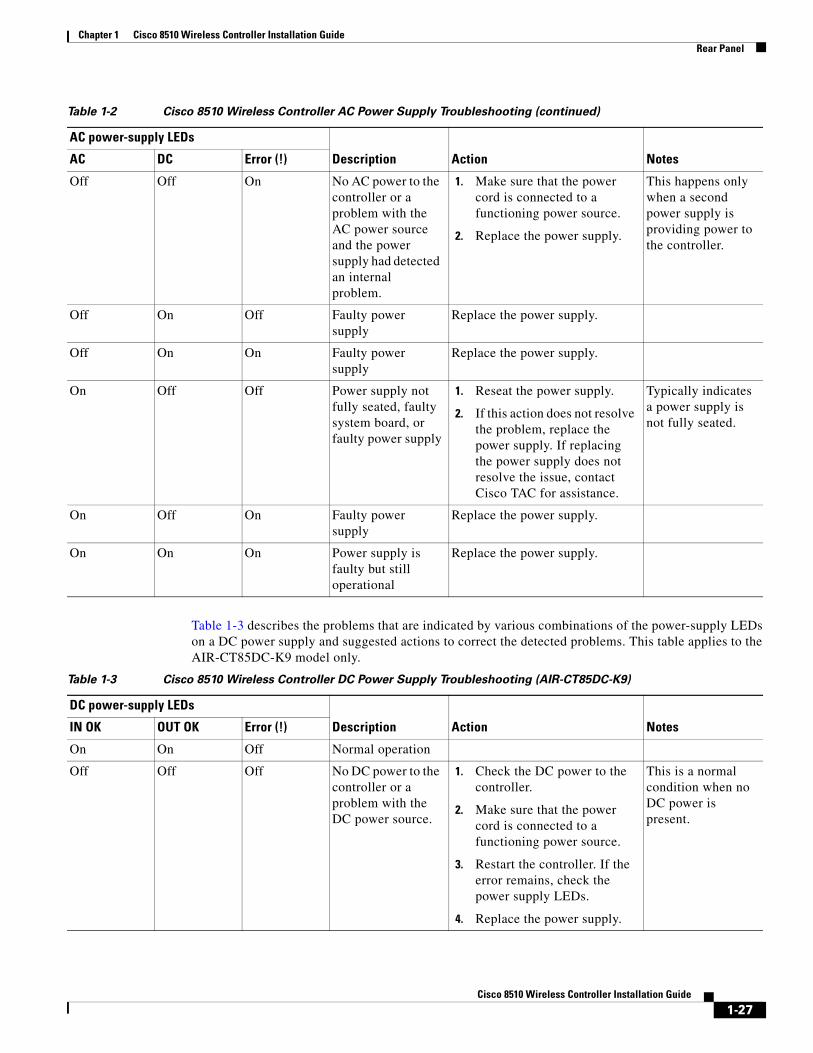
Replacing a Hot-Swap AC Power Supply The following section describes the type of AC power supply that the controller supports and other information that you must consider when you replace a failed power supply:
• The Cisco 8510 Wireless Controller comes with two 675-watt hot-swap 12-volt output power supplies that connect to power supply bays 1 and 2. The input voltage is 110 VAC or 220 VAC auto-sensing.
• Power supply 1 is the default/primary power supply. If power supply 1 fails, you must replace the power supply immediately.
• You can order replacement power supplies from Cisco. The replacement part PID is AIR-SRVR-PWR=.
• These power supplies are designed for parallel operation. In the event of a power-supply failure, the redundant power supply continues to power the system.
Caution The power control button on the device and the power switch on the power supply do not turn off the electrical current supplied to the device. The device also might have more than one power cord. To remove all electrical current from the device, ensure that all power cords are disconnected from the power source.
Caution Never remove the cover on a power supply or any part that has the following label attached. Hazardous voltage, current, and energy levels are present inside any component that has this label attached. There are no serviceable parts inside these components. If you suspect a problem with one of these parts, contact a service technician.
To install a hot-swap power supply, complete the following steps.
Step 1 Read the safety information in General Warnings, Regulatory and Safety, page 1-3.
Step 2 Touch the static-protective package that contains the hot-swap power supply to any unpainted metal surface on the controller; then, remove the power supply from the package and place it on a static-protective surface.
1-31Cisco 8510 Wireless Controller Installation Guide

Chapter 1 Cisco 8510 Wireless Controller Installation Guide Replacing a Hot-Swap -48 VDC Power Supply
Step 3 Remove the failed power supply first. Grasp the handle on the rear of the power supply and slide the power supply out from the chassis.
Step 4 Grasp the handle on the rear of the power supply and slide the power supply forward into the power-supply bay until it clicks. Make sure that the power supply connects firmly into the power-supply connector.
Step 5 Route the power cord through the handle so that it does not accidentally become unplugged.
Step 6 Connect the power cord for the new power supply to the power-cord connector on the power supply.
Step 7 Connect the other end of the power cord to a properly grounded electrical outlet.
Step 8 Make sure that the AC power LED and the DC power LED on the AC power supply are lit, indicating that the power supply is operating correctly. The two green LEDs are to the right of the power-cord connector.
Replacing a Hot-Swap -48 VDC Power Supply
Caution Only trained service personnel are authorized to install and remove the -48 VDC power supply and make the connections to and disconnections from the -48 VDC power source. The customer is responsible for ensuring that only trained service personnel install or remove the -48 volt power cable.
Caution Do not use both AC and DC power supplies in the same controller. Install two DC power supplies in the AIR-CT85DC-K9 and two AC power supplies in the AIR-CT8510-K9. Never install a combination of an AC and DC power supply in the controller.
Powersupplyfiller
Powersupply
Powersupplyrelease tab
2551
35
1-32Cisco 8510 Wireless Controller Installation Guide

Chapter 1 Cisco 8510 Wireless Controller Installation Guide Replacing a Hot-Swap -48 VDC Power Supply
Use this procedure for connecting and disconnecting the power cable from the rear of the unit.
Figure 1-10 DC Power Supply
Notes1. It is the customer's responsibility to supply the necessary power cable.
To reduce the risk of electric shock or energy hazards:
– Use a circuit breaker that is rated at 25 amps.
– Use 2.5 mm2 (12 AWG) at 90° C copper wire.
– Torque the wiring-terminal screws to 0.62 newton-meters (5.5 inch-pounds).
For more information, see Statement 34, page 1-35.
2. If the power source requires ring terminals, you must use a crimping tool to install the ring terminals to the power cord wires. The ring terminals must be UL approved and must accommodate the wire that is described in Note 1.
Statement 29
Caution This equipment is designed to permit the connection of the earthed conductor of the DC supply circuit to the earthing conductor at the equipment.
This equipment is designed to permit the connection of the earthed conductor of the DC supply circuit to the earthing conductor at the equipment. If this connection is made, all of the following conditions must be met:
1-33Cisco 8510 Wireless Controller Installation Guide

Chapter 1 Cisco 8510 Wireless Controller Installation Guide Replacing a Hot-Swap -48 VDC Power Supply
• This equipment shall be connected directly to the DC supply system earthing electrode conductor or to a bonding jumper from an earthing terminal bar or bus to which the DC supply system earthing electrode conductor is connected.
• This equipment shall be located in the same immediate area (such as, adjacent cabinets) as any other equipment that has a connection between the earthed conductor of the same DC supply circuit and the earthing conductor, and also the point of earthing of the DC system. The DC system shall not be earthed elsewhere.
• The DC supply source shall be located within the same premises as this equipment.
• Switching or disconnecting devices shall not be in the earthed circuit conductor between the DC source and the point of connection of the earthing electrode conductor.
Statement 31
Warning Electrical current from power, telephone, and communication cables is hazardous.
To avoid a shock hazard:
• Do not connect or disconnect any cables or perform installation, maintenance, or reconfiguration of this product during an electrical storm.
• Connect all power cords to a properly wired and grounded power source.
• Connect to properly wired power sources any equipment that will be attached to this product.
• When possible, use one hand only to connect or disconnect signal cables.
• Never turn on any equipment when there is evidence of fire, water, or structural damage.
• Disconnect the attached AC power cords, DC power sources, network connections, telecommunications systems, and serial cables before you open the device covers, unless you are instructed otherwise in the installation and configuration procedures.
• Connect and disconnect cables as described in the following table when you install, move, or open covers on this product or attached devices.
1-34Cisco 8510 Wireless Controller Installation Guide

Chapter 1 Cisco 8510 Wireless Controller Installation Guide Replacing a Hot-Swap -48 VDC Power Supply
Statement 33
Caution This product does not provide a power control button. The product also might have more than one power cord. To remove all electrical current from the product, make sure that all power cords are disconnected from the power source.
Statement 34
Caution To reduce the risk of electric shock or energy hazards:
• This equipment must be installed by trained service personnel in a restricted-access location, as defined by the NEC and IEC 60950-1, First Edition, The Standard for Safety of Information Technology Equipment.
To Connect To Disconnect
1. Turn off all power sources and equipment that is to be attached to this product.
2. Attach signal cables to the product.
3. Attach power cords to the product.
• For AC systems, use appliance inlets.
• For DC systems, ensure correct polarity of -48 VDC connections: RTN is + and -48 VDC is -. Earth ground should use a two-hole lug for safety.
4. Attach signal cables to other devices.
5. Connect power cords to their sources.
6. Turn on all the power sources.
1. Turn OFF all power sources and equipment that is to be attached to this product.
• For AC systems, remove all power cords from the chassis power receptacles or interrupt power at the AC power distribution unit.
• For DC systems, disconnect DC power sources at the breaker panel or by turning off the power source. Then, remove the DC cables.
2. Remove the signal cables from the connectors.
3. Remove all cables from the devices.
1-35Cisco 8510 Wireless Controller Installation Guide

Chapter 1 Cisco 8510 Wireless Controller Installation Guide Replacing a Hot-Swap -48 VDC Power Supply
• Connect the equipment to a properly grounded safety extra low voltage (SELV) source. A SELV source is a secondary circuit that is designed so that normal and single fault conditions do not cause the voltages to exceed a safe level (60 V direct current).
• Incorporate a readily available approved and rated disconnect device in the field wiring.
• See the specifications in the product documentation for the required circuit-breaker rating for branch circuit overcurrent protection.
• Use copper wire conductors only.
• See the specifications in the product documentation for the required torque values for the wiring-terminal screws.
Safety Information
To install the DC power supply, complete the following steps:
Step 1 If the controller is operating, turn off the server and peripheral devices.
Step 2 Turn off the circuit breaker for the DC power source to which the new power supply will be connected. Disconnect the power cord from the DC power source.
Step 3 Attach the DC power cable to the new power supply.
1-36Cisco 8510 Wireless Controller Installation Guide

Chapter 1 Cisco 8510 Wireless Controller Installation Guide Replacing a Hot-Swap -48 VDC Power Supply
Figure 1-11 Close Up of Cisco 8510 Wireless Controller DC Power Supply LEDs
Step 4 Connect the other ends of the DC power cable to the DC power source. Cut the wires to the correct length, but do not cut them shorter than 150 mm (6 in.). If the power source requires ring terminals, you must use a crimping tool to install the ring terminals to the power cord wires. The ring terminals must be UL approved and must accommodate the wires that are described in Note 1. The minimum nominal thread diameter of a pillar or stud type of terminal must be 4 mm; for a screw type of terminal the diameter must be 5.0 mm.
Step 5 Turn on the circuit breaker for the DC power source to which the new power supply is connected.
Step 6 Make sure that the green power LEDs on the power supply are lit, indicating that the power supply is operating correctly.
1-37Cisco 8510 Wireless Controller Installation Guide

Chapter 1 Cisco 8510 Wireless Controller Installation Guide Removing DC Power Supply from Controller
Removing DC Power Supply from ControllerTo remove the DC power supply from the controller, complete the following steps:
Step 1 Turn off the controller and peripheral devices.
Step 2 Disconnect the DC power cable from the DC power source (turn off the circuit breaker).
Step 3 Remove the DC power cable from the rear of the power supply.
Step 4 Grasp the power supply handle.
Step 5 Press and hold the orange release latch to the left.
Step 6 Pull the power supply part of the way out of the bay.
Step 7 Release the release latch; then, support the power supply and pull it the rest of the way out of the bay.
1-38Cisco 8510 Wireless Controller Installation Guide

Chapter 1 Cisco 8510 Wireless Controller Installation Guide Connecting the Cables
Connecting the Cables Figure 1-12 shows the locations of the input and output connectors on the front of the controller.
Figure 1-12 Front of Cisco 8510 Wireless Controller
Figure 1-13 shows the locations of the input and output connectors on the rear of the controller.
Figure 1-13 Rear of Cisco 8510 Wireless Controller
Connecting and Using the CLI ConsoleFor initial system configuration, use the command-line interface (CLI) console. The CLI console connects to the controller back-panel DB9 console port. Figure 1-6 on page 1-23 shows the console port on the back panel of the controller. Back panel components are described in Rear Panel Components, page 1-23.
Use these terminal emulator settings for the CLI console session:
• 9600 baud
• 8 data bits
• no flow control
• 1 stop bit
• no parity
Video connector
USB 1connector
USB 2connector
2551
30282303
AC
DC
AC
DC
IMM 10/100 MbpsEthernet port
Service port HA port
Video connector
Serialconnector
USB 3connector
USB 5connector(Not used)
Power connectors
10G port 1 10G port 2
USB 4connector
Console port(Not used)
1-39Cisco 8510 Wireless Controller Installation Guide

Chapter 1 Cisco 8510 Wireless Controller Installation Guide Powering On the Controller
Powering On the Controller
Connecting the AC Version of the 8510 [AIR-CT8510-K9] to a Power SourceWhen you apply AC power to a controller, the bootup script initializes the operating system and its stored configurations. You are prompted to enter a user ID and password and enter key configuration details.
Follow these steps to power up the controller.
Step 1 Plug an AC power cord into the back of the two power supplies (Figure 1-6 on page 1-23). If only one power supply is connected to a power source, the system will still function correctly but the monitoring components of the controller will detect the absence of the second power supply and will raise an alarm. Connect the other end of the power cord to a properly grounded 100 to 240 VAC 50/60 Hz electrical outlet.
The end of the power cord that plugs into the controller conforms with the IEC 320 standard.
Step 2 Use the front-panel Power On/Standby button, located in the operator information panel, to turn the controller on (Figure 1-3 on page 1-18).
Step 3 At the login prompt, enter the controller operating user ID and password. The default user ID is root and the default password is password.
The user ID and password are case sensitive.
You are now logged into the controller operating system.
Continue to the “Running the Bootup Script and Power-On Self Test” section on page 1-40.
Connecting the DC Version of the 8510 [AIR-CT85DC-K9] to a Power Source1. It is the customer's responsibility to supply the necessary power cable to connect the DC power
supplies to a DC power source.
To reduce the risk of electric shock or energy hazards:
– Use a circuit breaker that is rated at 25 amps.
– Use 2.5 mm2 (12 AWG) at 90° C copper wire.
– Torque the wiring-terminal screws to 0.62 newton-meters (5.5 inch-pounds).1-35
2. If the power source requires ring terminals, you must use a crimping tool to install the ring terminals to the power cord wires
Running the Bootup Script and Power-On Self TestWhen you plug the controller into an AC power source, the bootup script initializes the system, verifies the hardware configuration, loads its microcode into memory, verifies its operating system software load, and initializes itself with its stored configurations. Before performing this test, you should connect your terminal emulator application to the controller’s CLI console as described in the “Connecting and Using the CLI Console” section on page 1-39. Follow these steps to run the bootup script and conduct the power-on self test (POST).
1-40Cisco 8510 Wireless Controller Installation Guide

Chapter 1 Cisco 8510 Wireless Controller Installation Guide Powering On the Controller
Step 1 Plug an AC power cord into the back of the controller and connect the other end to a grounded 100 to 240 VAC, 50/60 Hz electrical outlet. Be sure to connect both power supplies to a power source.
Step 2 Turn on the power supply.
Step 3 Observe the bootup on the CLI screen.
The bootup script displays operating system software initialization (code download and POST verification) and basic configuration as shown in the following sample bootup display:
LSI MegaRAID SAS-MFI BIOS Version 4.19.00 (Build October 19, 2010) Copyright(c) 2010 LSI Corporation HA -0 (Bus 1 Dev 0) ServeRAID M1015 SAS/SATA Controller 0 JBOD(s) found on the host adapter 0 JBOD(s) handled by BIOS 1 Virtual Drive(s) found on the host adapter. 1 Virtual Drive(s) handled by BIOS Cisco Bootloader (Version 7.0.110.30)
.o88b. d888888b .d8888. .o88b. .d88b. d8P Y8 `88' 88' YP d8P Y8 .8P Y8. 8P 88 `8bo. 8P 88 88 8b 88 `Y8b. 8b 88 88 Y8b d8 .88. db 8D Y8b d8 `8b d8' `Y88P' Y888888P `8888Y' `Y88P' `Y88P'
Booting Primary Image...Press <ESC> now to access the Boot Menu...
Step 4 If desired, press Esc to display the Bootloader Boot Options menu.
Boot Options
Please choose an option from below:
1. Run primary image2. Run backup image3. Manually update images4. Change active boot image5. Clear Configuration
Please enter your choice:
Note Enter 1 to run the current software, enter 2 to run the previous software, or enter 4 to run the current software and set the controller configuration to factory defaults. Do not choose the other options unless directed to do so.
Step 5 The rest of the process takes two to three minutes. Do not reboot the controller until the user login prompt appears.
Booting ‘Primary image’
Detecting Hardware . . .3INIT: version 2.86 bootingStarting the hotplug events dispatcher: udevd.Synthesizing the initial hotplug events...done.Waiting for /dev to be fully populated...done.Activating swap...done. Remounting root filesystem...done. Mounting local filesystems: mount none on /var/run type tmpfs (rw)none on /tmp type tmpfs (rw)
1-41Cisco 8510 Wireless Controller Installation Guide

Chapter 1 Cisco 8510 Wireless Controller Installation Guide Using the Startup Wizard
Setting up networking ....Starting hotplug subsystem: pci pci [success] usb usb [success] isapnp isapnp [success] ide ide [success] input input [success] scsi scsi [success]done.Starting portmap daemon....Octeon Found...Detecting Hardware ...Booting Octeon...Using user supplied board name: nic_xle_10gAll cores in reset, skipping soft reset.Using bootloader image: /octeon/u-boot-octeon_nic_xle_10g_pciboot.binInitialized 2048 MBytes of DRAMINIT: Entering runlevel: 3
Cryptographic library self-test....passed!XML config selectedValidating XML configurationocteon_device_init: found 1 DPsCisco is a trademark of Cisco Systems, Inc.Software Copyright Cisco Systems, Inc. All rights reserved.
Cisco AireOS Version 7.0.114.110
. . .
Starting Management Services: Web Server: ok CLI: ok Secure Web: ok License Agent: ok
(Cisco Controller)
Enter User Name (or ‘Recover-Config’ this one-time only to reset configuration to factory defaults)
User: adminPassword: ******(Cisco Controller)
Step 6 If the controller passes the power-on self test, the bootup script runs the Startup Wizard, which prompts you for basic configuration input.
Using the Startup WizardBefore you can use the startup wizard, you must obtain the information discussed in the “Required Tools and Information” section on page 1-4.
1-42Cisco 8510 Wireless Controller Installation Guide

Chapter 1 Cisco 8510 Wireless Controller Installation Guide Using the Startup Wizard
Note The available options appear in brackets after each configuration parameter. The default value appears in all uppercase letters.
Note Press the hyphen key if you need to return to the previous command line.
To configure the controller for basic operation using the Startup Wizard, follow these steps:
Step 1 When prompted to terminate the AutoInstall process, enter yes. If you do not enter yes, the AutoInstall process begins after 30 seconds.
Welcome to the Cisco Wizard Configuration ToolUse the '-' character to backup
Would you like to terminate autoinstall? [yes]:AUTO-INSTALL: starting now...rc = 0
Note The AutoInstall feature downloads a configuration file from a TFTP server and then loads the configuration onto the controller automatically.
Step 2 Enter the system name, which is the name you want to assign to the controller. You can enter up to 31 ASCII characters.
System Name [Cisco_d9:3d:66] (31 characters max):AUTO-INSTALL: no interfaces registered.
AUTO-INSTALL: process terminated -- no configuration loaded
Step 3 Enter the administrative username and password to be assigned to this controller. You can enter up to 24 ASCII characters for each.
Enter Administrative User Name (24 characters max): adminEnter Administrative Password (3 to 24 characters): ******Re-enter Administrative Password : ******
Step 4 If you want the controller's service-port interface to obtain an IP address from a DHCP server or not planning to use the Service Port, enter DHCP. If you want to assign a static IP address to the service-port interface, enter static.
Service Interface IP Address Configuration [static][DHCP]: static
Note The service-port interface controls communications through the service port. Its IP address must be on a different subnet from the management interface. This configuration enables you to manage the controller directly or through a dedicated management network to ensure service access during network downtime.
Step 5 If you entered static in Step 4, enter the IP address and netmask for the service-port interface on the next two lines.
Service Interface IP Address: 172.19.30.18Service Interface Netmask: 255.255.254.0
1-43Cisco 8510 Wireless Controller Installation Guide

Chapter 1 Cisco 8510 Wireless Controller Installation Guide Using the Startup Wizard
Step 6 Enter the IP address, netmask, default router IP address, optional VLAN identifier (a valid VLAN identifier or 0 for an untagged VLAN), and the port number for the management interface.
Note The VLAN identifier should be set to match the switch interface configuration.
Management Interface IP Address: 192.168.1.10Management Interface Netmask: 255.255.0.0Management Interface Default Router: 192.168.1.1Management Interface VLAN Identifier (0 = untagged): 192Management Interface Port Num [1 to 2]: 1
Step 7 Enter the IP address of the default DHCP server that will supply IP addresses to clients, the controller’s management interface.
Management Interface DHCP Server IP Address: 192.168.1.1
Note The management interface is the default interface for in-band management of the controller and connectivity to enterprise such as AAA servers.
Step 8 Enter the IP address of the controller’s virtual interface, which will be used by all controller Layer 3 security and mobility managers. You should enter a fictitious, unassigned IP address, such as 192.0.2.1.
Virtual Gateway IP Address: 192.0.2.1
Note The virtual interface is used to support mobility management, DHCP relay, and embedded Layer 3 security such as guest web authentication and VPN termination. All controllers within a mobility group must be configured with the same virtual interface IP address.
Step 9 If desired, enter the name of the mobility group/RF group to which you want the controller to belong.
Mobility/RF Group Name: amb
Note Although the name that you enter here is assigned to both the mobility group and the RF group, these groups are not identical. Both groups define clusters of controllers, but they have different purposes. All of the controllers in an RF group are usually also in the same mobility group and vice versa. However, a mobility group facilitates scalable, system-wide mobility and controller redundancy while an RF group facilitates scalable, system-wide dynamic RF management.
Step 10 Enter the network name, or service set identifier (SSID). The initial SSID enables basic functionality of the controller and allows access points that have joined the controller to enable their radios.
Network Name (SSID): amb
Step 11 Enter yes to enable DHCP proxy or no to disable DHCP proxy.
Configure DHCP Bridging Mode [yes][NO]:yes
Step 12 Enter yes to allow clients to assign their own IP address or no to make clients request an IP address from a DHCP server.
Allow Static IP Addresses [YES][no]:
Step 13 To configure a RADIUS server now, enter yes and then enter the IP address, communication port, and secret key of the RADIUS server. Otherwise, enter no.
1-44Cisco 8510 Wireless Controller Installation Guide

Chapter 1 Cisco 8510 Wireless Controller Installation Guide Using the Startup Wizard
Configure a RADIUS Server now? [YES][no]: noWarning! The default WLAN security policy requires a RADIUS server.Please see documentation for more details.
Step 14 Enter the code for the country in which the controller will be used.
Enter Country Code list (enter 'help' for a list of countries) [US]:
Note Enter help to view the list of available country codes.
Step 15 Enter yes to enable or no to disable each of the 802.11b, 802.11a, and 802.11g lightweight access point networks.
Enable 802.11b Network [YES][no]:Enable 802.11a Network [YES][no]:Enable 802.11g Network [YES][no]:
Note 802.11n is always enabled.
Step 16 Enter yes to enable or no to disable the controller’s radio resource management (RRM) auto RF feature.
Enable Auto-RF [YES][no]:
Note The auto RF feature enables the controller to automatically form an RF group with other controllers. The group dynamically elects a leader to optimize RRM parameter settings, such as channel and transmit power assignment, for the group.
Step 17 If you want the controller to receive its time setting from an external Network Time Protocol (NTP) server when it powers up, enter yes to configure an NTP server. Otherwise, enter no.
Configure a NTP server now? [YES][no]: no
Step 18 If you entered no in the previous step and want to manually configure the system time on your controller now, enter yes. If you do not want to configure the system time now, enter no.
Configure the system time now? [YES][no]:
Step 19 If you entered yes in the previous step, enter the current date in MM/DD/YY format and the current time in HH:MM:SS format.
Enter the date in MM/DD/YY format: 03/28/11Enter the time in HH:MM:SS format: 14:36:30
Step 20 When prompted to verify that the configuration is correct, enter yes or no.
Configuration correct? If yes, system will save it and reset. [yes][NO]: yes
The controller saves your configuration, reboots, and prompts you to log in.
Configuration saved!Resetting system with new configuration...
Configuration saved!Resetting system with new configuration...SoftDog: Unexpected close, not stopping watchdog!INIT: Switching to runlevel: 6INIT: Sending processes the TERM signalStopping portmap daemon....
1-45Cisco 8510 Wireless Controller Installation Guide

Chapter 1 Cisco 8510 Wireless Controller Installation Guide Using the Startup Wizard
Sending all processes the TERM signal... done.
Note The Cisco 8510 Wireless Controller can be configured as mobility controller. Mobility Oracle is not supported on the controller.
Logging into the ControllerFollow these steps to log into the controller.
Step 1 Enter a valid username and password to log into the controller CLI.
Note The administrative username and password you created in the Startup Wizard are case sensitive.
Step 2 The CLI displays the root level system prompt:
#(system prompt)>
The system prompt can be any alphanumeric string up to 31 characters. You can change it by entering the config prompt command.
Note The CLI automatically logs you out without saving any changes after 5 minutes of inactivity. You can set the automatic logout from 0 (never log out) to 160 minutes using the config serial timeout command.
Note Cisco Aironet lightweight access points do not connect to the Cisco 8510 Wireless Controller if the date and time are not set properly. Set the current date and time on the controller before allowing the access points to connect to it.
Verifying Interface Settings and Port OperationFollow these steps to verify that your interface configurations have been set properly and the controller’s ports are operational.
Step 1 Enter show interface summary. The controller’s current interface configurations appear:
Interface Name Port Vlan Id IP Address Type Ap Mgr Guest-------------------------------- ---- -------- -------------- ------- ------- -----management 1 192 192.168.1.10 Static Yes Noservice-port N/A N/A 172.19.30.18 Static No Novirtual N/A N/A 192.0.2.1 Static No No
Step 2 Enter show port summary. The following information appears, showing the status of the controller’s distribution system ports, which serve as the data path between the controller and Cisco lightweight access points and to which the controller’s management interface is mapped.
1-46Cisco 8510 Wireless Controller Installation Guide

Chapter 1 Cisco 8510 Wireless Controller Installation Guide Using the Startup Wizard
STP Admin Physical Physical Link Link Pr Type Stat Mode Mode Status Status Trap POE-- ------- ---- ------- ---------- ---------- ------ ------- -------1 Normal Forw Enable Auto 10000 Full Up Enable N/A2 Normal Forw Enable Auto 10000 Full Up Enable N/A
A link status of Up indicates that the controller’s ports are fully operational.
Connecting the Network (Distribution System)The SFP+ module supported by the Cisco 8510 Wireless Controller is the Cisco SFP-10G-SR.
Cisco SFP-10G-SR: The Cisco 10GBASE-SR Module supports a link length of 26m on standard Fiber Distributed Data Interface (FDDI)-grade multimode fiber (MMF). Using 2000 MHz*km MMF(OM3), up to 300m link lengths are possible.
Depending on the distribution system physical port to be assigned, use only standard compliant fiber-optic cables to connect the network equipment to the controller
Note Only connections with patch cords with PC or UPC connectors are supported. Patch cords with APC connectors are not supported. All cables and cable assemblies used must be compliant with the standards specified in the standards section.
Connecting the Controller’s Service Port (Optional) The service port is controlled by the service-port interface and is reserved for out-of-band management of the controller and system recovery and maintenance in the event of a network failure. The service-port interface enables the controller to be managed on an interface different from the one used for your network traffic. Use of the service port is optional.
You can perform out-of-band controller management from a PC running a terminal emulation program or a PC running Cisco WCS, a network management tool that enables you to configure and monitor a network of controllers, or the controller GUI. However, you must first connect the PC to the controller’s service port in one of two ways:
• Use an Ethernet cross-over cable to connect the PC directly to the controller’s service port.
• For a remote connection (using Telnet or SSH) through a dedicated management network, use a Category 5, Category 5e, Category 6, or Category 7 Ethernet cable to connect the management network to the controller’s service port and the appropriate cable to connect the PC to the management network.
Connecting Access PointsAfter you have configured the controller, use Category-5, Category-5e, Category-6, or Category-7 Ethernet cables to connect Cisco lightweight access points to the network.
As soon as the controller is operational, it starts to scan for access points. When it detects an access point, it records the access-point MAC address in its database. The controller radio resource management (RRM) feature then automatically configures the access point to start sending and allowing clients to associate.
1-47Cisco 8510 Wireless Controller Installation Guide

Chapter 1 Cisco 8510 Wireless Controller Installation Guide Controller Specifications
You have prepared the controller for basic operation. Refer to the Cisco Wireless LAN Controller Configuration Guide for information on configuring the controller to meet the specific needs of your wireless network.
Controller Specifications
Obtaining Documentation and Submitting a Service RequestFor information on obtaining documentation, submitting a service request, and gathering additional information, see the monthly What’s New in Cisco Product Documentation, which also lists all new and revised Cisco technical documentation:
http://www.cisco.com/en/US/docs/general/whatsnew/whatsnew.html
Subscribe to the What’s New in Cisco Product Documentation as an RSS feed and set content to be delivered directly to your desktop using a reader application. The RSS feeds are a free service. Cisco currently supports RSS Version 2.0.
Cisco 90-Day Limited Hardware Warranty TermsThere are special terms applicable to your hardware warranty and various that you can use during the warranty period. Your formal Warranty Statement, including the warranties and license agreements applicable to Cisco software, is available on Cisco.com. Follow these steps to access and download the Cisco Information Packet and your warranty and license agreements from Cisco.com.
1. Launch your browser, and go to this URL:
http://www.cisco.com/en/US/products/prod_warranties_listing.html
The Warranties and License Agreements page appears.
2. To read the Cisco Information Packet, follow these steps:
a. Click the Information Packet Number field, and make sure that the part number 78-5235-03B0 is highlighted.
b. Select the language in which you would like to read the document.
c. Click Go.
The Cisco Limited Warranty and Software License page from the Information Packet appears.
Chassis Dimensions Width = 17.3 in (44.0 cm)
Depth = 21.20 in (53.9 cm)
Height = 1.75 in (4.45 cm)
Weight 20 lbs (9.1 kg) with two power supplies installed
Temperature range Operating: 50 to 95°F (10 to 35°C)
Storage: –40 to 140°F (–40 to 60°C)
Humidity Operating humidity: 20 - 80%, non-condensing
Storage humidity: up to 95%
1-48Cisco 8510 Wireless Controller Installation Guide

Chapter 1 Cisco 8510 Wireless Controller Installation Guide Cisco 90-Day Limited Hardware Warranty Terms
d. Read the document online, or click the PDF icon to download and print the document in Adobe Portable Document Format (PDF).
Note You must have Adobe Acrobat Reader to view and print PDF files. You can download the reader from Adobe’s website: http://www.adobe.com
3. To read translated and localized warranty information about your product, follow these steps:
a. Enter this part number in the Warranty Document Number field:
78-5236-01C0
b. Select the language in which you would like to read the document.
c. Click Go.
The Cisco warranty page appears.
d. Review the document online, or click the PDF icon to download and print the document in Adobe Portable Document Format (PDF).
Click this link to browse to the Cisco Support and Documentation page:
http://www.cisco.com/c/en/us/support/index.html
Duration of Hardware Warranty
Ninety (90) days.
Replacement, Repair, or Refund Policy for Hardware
Cisco or its service center will use commercially reasonable efforts to ship a replacement part within ten (10) working days after receipt of a Return Materials Authorization (RMA) request. Actual delivery times can vary, depending on the customer location.
Cisco reserves the right to refund the purchase price as its exclusive warranty remedy.
To Receive a Return Materials Authorization (RMA) Number
Contact the company from whom you purchased the product. If you purchased the product directly from Cisco, contact your Cisco Sales and Service Representative.
Complete the information below, and keep it for reference:
Company product purchased from
Company telephone number
Product model number
Product serial number
Maintenance contract number
1-49Cisco 8510 Wireless Controller Installation Guide
Chapter 1 Cisco 8510 Wireless Controller Installation Guide Cisco 90-Day Limited Hardware Warranty Terms
1-50Cisco 8510 Wireless Controller Installation Guide