Embed Size (px)
DESCRIPTION
7600
Citation preview
Americas HeadquartersCisco Systems, Inc.170 West Tasman DriveSan Jose, CA 95134-1706 USAhttp://www.cisco.comTel: 408 526-4000
800 553-NETS (6387)Fax: 408 527-0883
Cisco 7600 Series Router Module Installation Guide October 2010
Text Part Number: OL-5077-7

THE SPECIFICATIONS AND INFORMATION REGARDING THE PRODUCTS IN THIS MANUAL ARE SUBJECT TO CHANGE WITHOUT NOTICE. ALL STATEMENTS, INFORMATION, AND RECOMMENDATIONS IN THIS MANUAL ARE BELIEVED TO BE ACCURATE BUT ARE PRESENTED WITHOUT WARRANTY OF ANY KIND, EXPRESS OR IMPLIED. USERS MUST TAKE FULL RESPONSIBILITY FOR THEIR APPLICATION OF ANY PRODUCTS.
THE SOFTWARE LICENSE AND LIMITED WARRANTY FOR THE ACCOMPANYING PRODUCT ARE SET FORTH IN THE INFORMATION PACKET THAT SHIPPED WITH THE PRODUCT AND ARE INCORPORATED HEREIN BY THIS REFERENCE. IF YOU ARE UNABLE TO LOCATE THE SOFTWARE LICENSE OR LIMITED WARRANTY, CONTACT YOUR CISCO REPRESENTATIVE FOR A COPY.
The following information is for FCC compliance of Class A devices: This equipment has been tested and found to comply with the limits for a Class A digital device, pursuant to part 15 of the FCC rules. These limits are designed to provide reasonable protection against harmful interference when the equipment is operated in a commercial environment. This equipment generates, uses, and can radiate radio-frequency energy and, if not installed and used in accordance with the instruction manual, may cause harmful interference to radio communications. Operation of this equipment in a residential area is likely to cause harmful interference, in which case users will be required to correct the interference at their own expense.
The following information is for FCC compliance of Class B devices: The equipment described in this manual generates and may radiate radio-frequency energy. If it is not installed in accordance with Cisco’s installation instructions, it may cause interference with radio and television reception. This equipment has been tested and found to comply with the limits for a Class B digital device in accordance with the specifications in part 15 of the FCC rules. These specifications are designed to provide reasonable protection against such interference in a residential installation. However, there is no guarantee that interference will not occur in a particular installation.
Modifying the equipment without Cisco’s written authorization may result in the equipment no longer complying with FCC requirements for Class A or Class B digital devices. In that event, your right to use the equipment may be limited by FCC regulations, and you may be required to correct any interference to radio or television communications at your own expense.
You can determine whether your equipment is causing interference by turning it off. If the interference stops, it was probably caused by the Cisco equipment or one of its peripheral devices. If the equipment causes interference to radio or television reception, try to correct the interference by using one or more of the following measures:
• Turn the television or radio antenna until the interference stops.
• Move the equipment to one side or the other of the television or radio.
• Move the equipment farther away from the television or radio.
• Plug the equipment into an outlet that is on a different circuit from the television or radio. (That is, make certain the equipment and the television or radio are on circuits controlled by different circuit breakers or fuses.)
Modifications to this product not authorized by Cisco Systems, Inc. could void the FCC approval and negate your authority to operate the product.
The Cisco implementation of TCP header compression is an adaptation of a program developed by the University of California, Berkeley (UCB) as part of UCB’s public domain version of the UNIX operating system. All rights reserved. Copyright © 1981, Regents of the University of California.
NOTWITHSTANDING ANY OTHER WARRANTY HEREIN, ALL DOCUMENT FILES AND SOFTWARE OF THESE SUPPLIERS ARE PROVIDED “AS IS” WITH ALL FAULTS. CISCO AND THE ABOVE-NAMED SUPPLIERS DISCLAIM ALL WARRANTIES, EXPRESSED OR IMPLIED, INCLUDING, WITHOUT LIMITATION, THOSE OF MERCHANTABILITY, FITNESS FOR A PARTICULAR PURPOSE AND NONINFRINGEMENT OR ARISING FROM A COURSE OF DEALING, USAGE, OR TRADE PRACTICE.
IN NO EVENT SHALL CISCO OR ITS SUPPLIERS BE LIABLE FOR ANY INDIRECT, SPECIAL, CONSEQUENTIAL, OR INCIDENTAL DAMAGES, INCLUDING, WITHOUT LIMITATION, LOST PROFITS OR LOSS OR DAMAGE TO DATA ARISING OUT OF THE USE OR INABILITY TO USE THIS MANUAL, EVEN IF CISCO OR ITS SUPPLIERS HAVE BEEN ADVISED OF THE POSSIBILITY OF SUCH DAMAGES.
CCDE, CCENT, CCSI, Cisco Eos, Cisco Explorer, Cisco HealthPresence, Cisco IronPort, the Cisco logo, Cisco Nurse Connect, Cisco Pulse, Cisco SensorBase, Cisco StackPower, Cisco StadiumVision, Cisco TelePresence, Cisco TrustSec, Cisco Unified Computing System, Cisco WebEx, DCE, Flip Channels, Flip for Good, Flip Mino, Flipshare (Design), Flip Ultra, Flip Video, Flip Video (Design), Instant Broadband, and Welcome to the Human Network are trademarks; Changing the Way We Work, Live, Play, and Learn, Cisco Capital, Cisco Capital (Design), Cisco:Financed (Stylized), Cisco Store, Flip Gift Card, and One Million Acts of Green are service marks; and Access Registrar, Aironet, AllTouch, AsyncOS, Bringing the Meeting To You, Catalyst, CCDA, CCDP, CCIE, CCIP, CCNA, CCNP, CCSP, CCVP, Cisco, the Cisco Certified Internetwork Expert logo, Cisco IOS, Cisco Lumin, Cisco Nexus, Cisco Press, Cisco Systems, Cisco Systems Capital, the Cisco Systems logo, Cisco Unity, Collaboration Without Limitation, Continuum, EtherFast, EtherSwitch, Event Center, Explorer, Follow Me Browsing, GainMaker, iLYNX, IOS, iPhone, IronPort, the IronPort logo, Laser Link, LightStream, Linksys, MeetingPlace, MeetingPlace Chime Sound, MGX, Networkers, Networking Academy, PCNow, PIX, PowerKEY, PowerPanels, PowerTV, PowerTV (Design), PowerVu, Prisma, ProConnect, ROSA, SenderBase, SMARTnet, Spectrum Expert, StackWise, WebEx, and the WebEx logo are registered trademarks of Cisco and/or its affiliates in the United States and certain other countries.
All other trademarks mentioned in this document or website are the property of their respective owners. The use of the word partner does not imply a partnership relationship between Cisco and any other company. (1002R)
Copyright © 2010, Cisco Systems, Inc. All rights reserved.
OL-5077-7
C O N T E N T S
Preface 7
Document Revision History 1-7
Audience 1-7
Organization 1-7
Conventions 1-8
Warning Definition 1-10
Related Documentation 1-13
Obtaining Documentation 1-13
Cisco.com 1-13
Documentation CD-ROM 1-13
Ordering Documentation 1-14
Documentation Feedback 1-14
Obtaining Technical Assistance 1-14
Cisco.com 1-14
Technical Assistance Center 1-15
Obtaining Additional Publications and Information 1-16
C H A P T E R 1 Product Overview 1-1
Cisco 7600 Series Routers 1-1
Supported Hardware 1-1
Features 1-3
Supervisor Engines 1-4
LEDs 1-11
Reset Button 1-15
Console Port 1-15
Console Port Mode Switch 1-15
Switch Load Meter 1-16
PCMCIA Slot 1-16
Uplink Ports 1-16
Optical Services Modules 1-17
OC-3c POS OSM 1-17
OC-12c POS OSM 1-18
OC-48 POS OSM 1-18
OC-48 DPT/POS OSM 1-19
3Book Title
Contents
Channelized OC-12 OSM 1-19
OC-12 ATM OSM 1-20
2+4-Port Gigabit Ethernet WAN OSM 1-20
12-Port Channelized T3 OSM 1-20
OSM LED Descriptions 1-21
Catalyst 6500 Family Modules 1-24
FlexWAN Module (WS-X6182-2PA) 1-24
Enhanced FlexWAN Module (WS-X6582-2PA) 1-25
48-Port 10/100TX Switching Module (WS-X6348-RJ-45) 1-26
16-Port Gigabit Ethernet Switching Module (WS-X6516-GBIC) 1-26
Switch Fabric Module (WS-C6500-SFM) 1-27
Switch Fabric Module 2 (WS-X6500-SFM2) 1-27
Cisco Application Control Engine (ACE) Module (ACE10-6500-K9) 1-28
Catalyst 6000 Family Module LED Descriptions 1-29
SPA Interface Processors 1-29
7600-SIP-200 1-30
7600-SIP-400 1-30
7600-SIP-600 1-31
SIP LED Descriptions 1-31
Ethernet Services 20G Line Cards 1-31
7600-ES20-10G 1-32
7600-ES20-GE 1-33
Cisco 7600 Ethernet Services Plus Line Cards 1-33
Cisco 7600 ES+ 2TG3C, -3CXL Line Cards 1-34
Cisco 7600 ES+ 4TG3C, -4TG3CXL Line Cards 1-34
Cisco 7600 ES+ 20G3C, -20G3CXL Line Cards 1-35
Cisco 7600 ES+ 40G3C, -40G3CXL Line Cards 1-36
Port Addresses 1-37
Physical Interface Addresses 1-37
MAC Addresses 1-38
Hot Swapping Supervisor Engines and Modules 1-39
Power Management and Environmental Monitoring 1-39
OSM Technology Overview 1-39
SONET/SDH Overview 1-40
ATM Overview 1-40
C H A P T E R 2 Preparing for Installation 2-1
Safety Guidelines 2-1
General Precautions 2-1
4Book Title
OL-5077-7
Contents
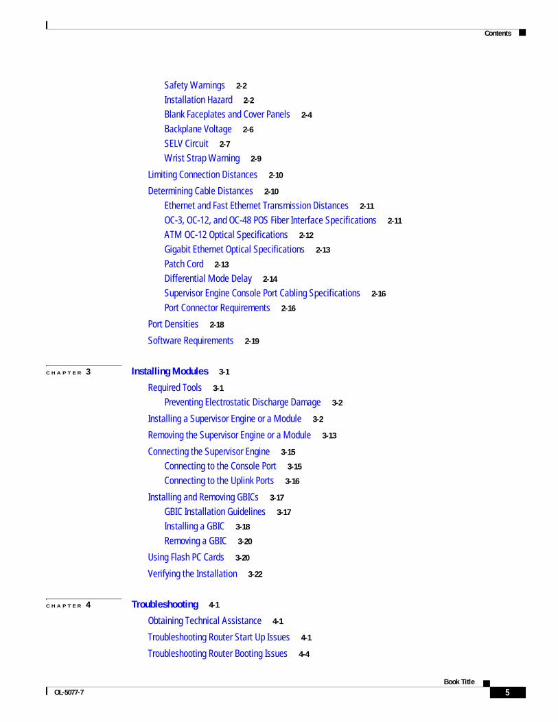
Safety Warnings 2-2
Installation Hazard 2-2
Blank Faceplates and Cover Panels 2-4
Backplane Voltage 2-6
SELV Circuit 2-7
Wrist Strap Warning 2-9
Limiting Connection Distances 2-10
Determining Cable Distances 2-10
Ethernet and Fast Ethernet Transmission Distances 2-11
OC-3, OC-12, and OC-48 POS Fiber Interface Specifications 2-11
ATM OC-12 Optical Specifications 2-12
Gigabit Ethernet Optical Specifications 2-13
Patch Cord 2-13
Differential Mode Delay 2-14
Supervisor Engine Console Port Cabling Specifications 2-16
Port Connector Requirements 2-16
Port Densities 2-18
Software Requirements 2-19
C H A P T E R 3 Installing Modules 3-1
Required Tools 3-1
Preventing Electrostatic Discharge Damage 3-2
Installing a Supervisor Engine or a Module 3-2
Removing the Supervisor Engine or a Module 3-13
Connecting the Supervisor Engine 3-15
Connecting to the Console Port 3-15
Connecting to the Uplink Ports 3-16
Installing and Removing GBICs 3-17
GBIC Installation Guidelines 3-17
Installing a GBIC 3-18
Removing a GBIC 3-20
Using Flash PC Cards 3-20
Verifying the Installation 3-22
C H A P T E R 4 Troubleshooting 4-1
Obtaining Technical Assistance 4-1
Troubleshooting Router Start Up Issues 4-1
Troubleshooting Router Booting Issues 4-4
5Book Title
OL-5077-7
Contents
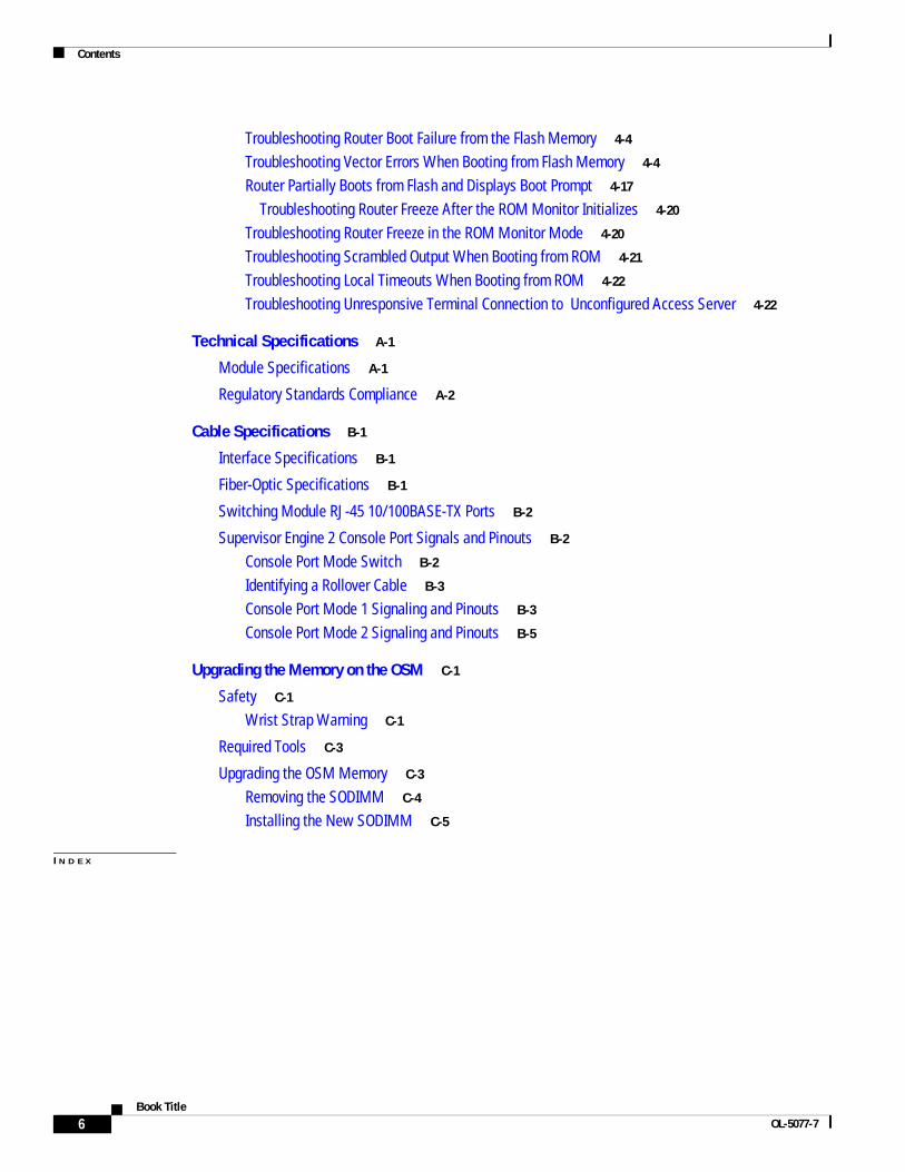
Troubleshooting Router Boot Failure from the Flash Memory 4-4
Troubleshooting Vector Errors When Booting from Flash Memory 4-4
Router Partially Boots from Flash and Displays Boot Prompt 4-17
Troubleshooting Router Freeze After the ROM Monitor Initializes 4-20
Troubleshooting Router Freeze in the ROM Monitor Mode 4-20
Troubleshooting Scrambled Output When Booting from ROM 4-21
Troubleshooting Local Timeouts When Booting from ROM 4-22
Troubleshooting Unresponsive Terminal Connection to Unconfigured Access Server 4-22
Technical Specifications A-1
Module Specifications A-1
Regulatory Standards Compliance A-2
Cable Specifications B-1
Interface Specifications B-1
Fiber-Optic Specifications B-1
Switching Module RJ-45 10/100BASE-TX Ports B-2
Supervisor Engine 2 Console Port Signals and Pinouts B-2
Console Port Mode Switch B-2
Identifying a Rollover Cable B-3
Console Port Mode 1 Signaling and Pinouts B-3
Console Port Mode 2 Signaling and Pinouts B-5
Upgrading the Memory on the OSM C-1
Safety C-1
Wrist Strap Warning C-1
Required Tools C-3
Upgrading the OSM Memory C-3
Removing the SODIMM C-4
Installing the New SODIMM C-5
I N D E X
6Book Title
OL-5077-7
Preface
This preface describes who should read the Cisco 7600 Series Router Module Installation Guide, how it is organized, and its document conventions.
Document Revision HistoryTable 1 records changes to this document.
AudienceOnly trained and qualified service personnel (as defined in IEC 60950 and AS/NZS3260) should install, replace, or service the equipment described in this publication.
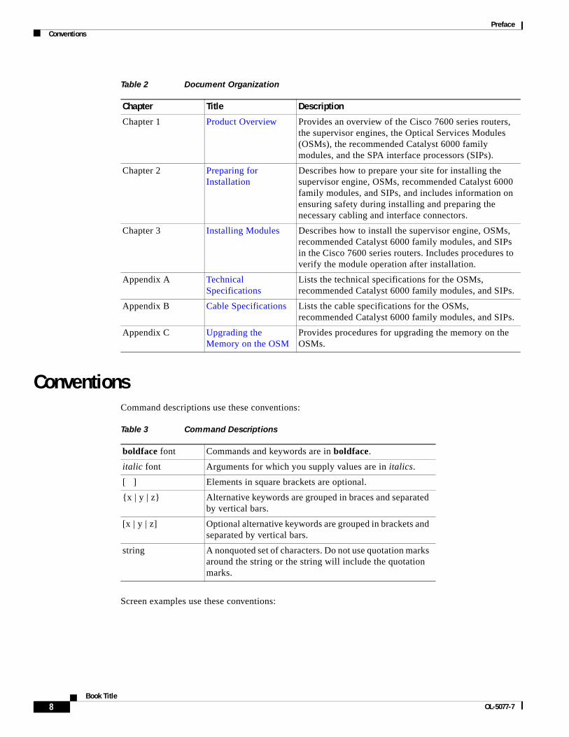
OrganizationTable 2 lists the document organization of this guide.
Table 1 Document Revision History
Revision Date Change Summary
OL-5077-7 September 2010 • Added troubleshooting information in Chapter 4, “Troubleshooting”.
OL-5077-6 October 2008 • Added ES+ line cards
OL-5077-5 February, 2007 • Added Route Switch Processor 720
• Added Ethernet Services 20G line cards
• Added Cisco Application Control Engine (ACE) module
OL-5077-4 December, 2005 • Added Supervisor Engine 32
OL-5077-3 April, 2005 • Added Cisco 7604 router
• Added Document Revision History table
7Book Title
OL-5077-7
PrefaceConventions
ConventionsCommand descriptions use these conventions:
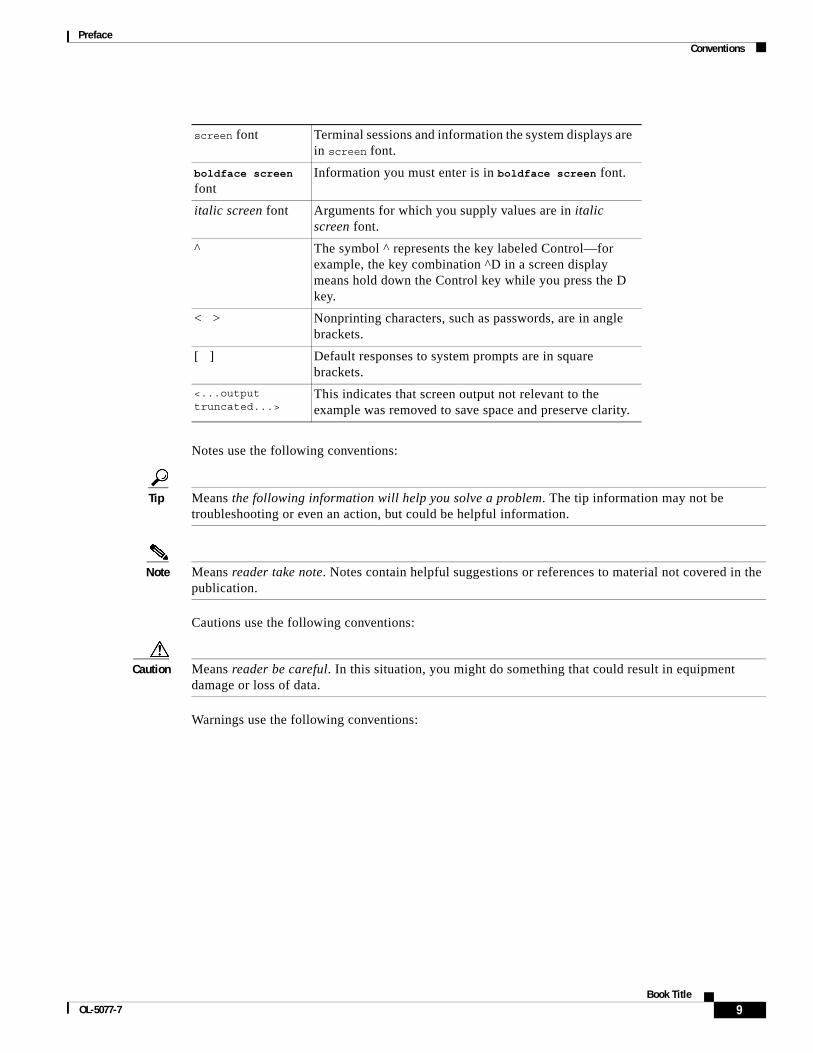
Screen examples use these conventions:
Table 2 Document Organization
Chapter Title Description
Chapter 1 Product Overview Provides an overview of the Cisco 7600 series routers, the supervisor engines, the Optical Services Modules (OSMs), the recommended Catalyst 6000 family modules, and the SPA interface processors (SIPs).
Chapter 2 Preparing for Installation
Describes how to prepare your site for installing the supervisor engine, OSMs, recommended Catalyst 6000 family modules, and SIPs, and includes information on ensuring safety during installing and preparing the necessary cabling and interface connectors.
Chapter 3 Installing Modules Describes how to install the supervisor engine, OSMs, recommended Catalyst 6000 family modules, and SIPs in the Cisco 7600 series routers. Includes procedures to verify the module operation after installation.
Appendix A Technical Specifications
Lists the technical specifications for the OSMs, recommended Catalyst 6000 family modules, and SIPs.
Appendix B Cable Specifications Lists the cable specifications for the OSMs, recommended Catalyst 6000 family modules, and SIPs.
Appendix C Upgrading the Memory on the OSM
Provides procedures for upgrading the memory on the OSMs.
Table 3 Command Descriptions
boldface font Commands and keywords are in boldface.
italic font Arguments for which you supply values are in italics.
[ ] Elements in square brackets are optional.
{x | y | z} Alternative keywords are grouped in braces and separated by vertical bars.
[x | y | z] Optional alternative keywords are grouped in brackets and separated by vertical bars.
string A nonquoted set of characters. Do not use quotation marks around the string or the string will include the quotation marks.
8Book Title
OL-5077-7
PrefaceConventions
Notes use the following conventions:
Tip Means the following information will help you solve a problem. The tip information may not be troubleshooting or even an action, but could be helpful information.
Note Means reader take note. Notes contain helpful suggestions or references to material not covered in the publication.
Cautions use the following conventions:
Caution Means reader be careful. In this situation, you might do something that could result in equipment damage or loss of data.
Warnings use the following conventions:
screen font Terminal sessions and information the system displays are in screen font.
boldface screen font
Information you must enter is in boldface screen font.
italic screen font Arguments for which you supply values are in italic screen font.
^ The symbol ^ represents the key labeled Control—for example, the key combination ^D in a screen display means hold down the Control key while you press the D key.
< > Nonprinting characters, such as passwords, are in angle brackets.
[ ] Default responses to system prompts are in square brackets.
<...output truncated...>
This indicates that screen output not relevant to the example was removed to save space and preserve clarity.
9Book Title
OL-5077-7

PrefaceConventions
Warning Definition
Warning IMPORTANT SAFETY INSTRUCTIONS
This warning symbol means danger. You are in a situation that could cause bodily injury. Before you work on any equipment, be aware of the hazards involved with electrical circuitry and be familiar with standard practices for preventing accidents. Use the statement number provided at the end of each warning to locate its translation in the translated safety warnings that accompanied this device. Statement 1071
SAVE THESE INSTRUCTIONS
Waarschuwing BELANGRIJKE VEILIGHEIDSINSTRUCTIES
Dit waarschuwingssymbool betekent gevaar. U verkeert in een situatie die lichamelijk letsel kan veroorzaken. Voordat u aan enige apparatuur gaat werken, dient u zich bewust te zijn van de bij elektrische schakelingen betrokken risico's en dient u op de hoogte te zijn van de standaard praktijken om ongelukken te voorkomen. Gebruik het nummer van de verklaring onderaan de waarschuwing als u een vertaling van de waarschuwing die bij het apparaat wordt geleverd, wilt raadplegen.
BEWAAR DEZE INSTRUCTIES
Varoitus TÄRKEITÄ TURVALLISUUSOHJEITA
Tämä varoitusmerkki merkitsee vaaraa. Tilanne voi aiheuttaa ruumiillisia vammoja. Ennen kuin käsittelet laitteistoa, huomioi sähköpiirien käsittelemiseen liittyvät riskit ja tutustu onnettomuuksien yleisiin ehkäisytapoihin. Turvallisuusvaroitusten käännökset löytyvät laitteen mukana toimitettujen käännettyjen turvallisuusvaroitusten joukosta varoitusten lopussa näkyvien lausuntonumeroiden avulla.
SÄILYTÄ NÄMÄ OHJEET
Attention IMPORTANTES INFORMATIONS DE SÉCURITÉ
Ce symbole d'avertissement indique un danger. Vous vous trouvez dans une situation pouvant entraîner des blessures ou des dommages corporels. Avant de travailler sur un équipement, soyez conscient des dangers liés aux circuits électriques et familiarisez-vous avec les procédures couramment utilisées pour éviter les accidents. Pour prendre connaissance des traductions des avertissements figurant dans les consignes de sécurité traduites qui accompagnent cet appareil, référez-vous au numéro de l'instruction situé à la fin de chaque avertissement.
CONSERVEZ CES INFORMATIONS
10Book Title
OL-5077-7
PrefaceConventions
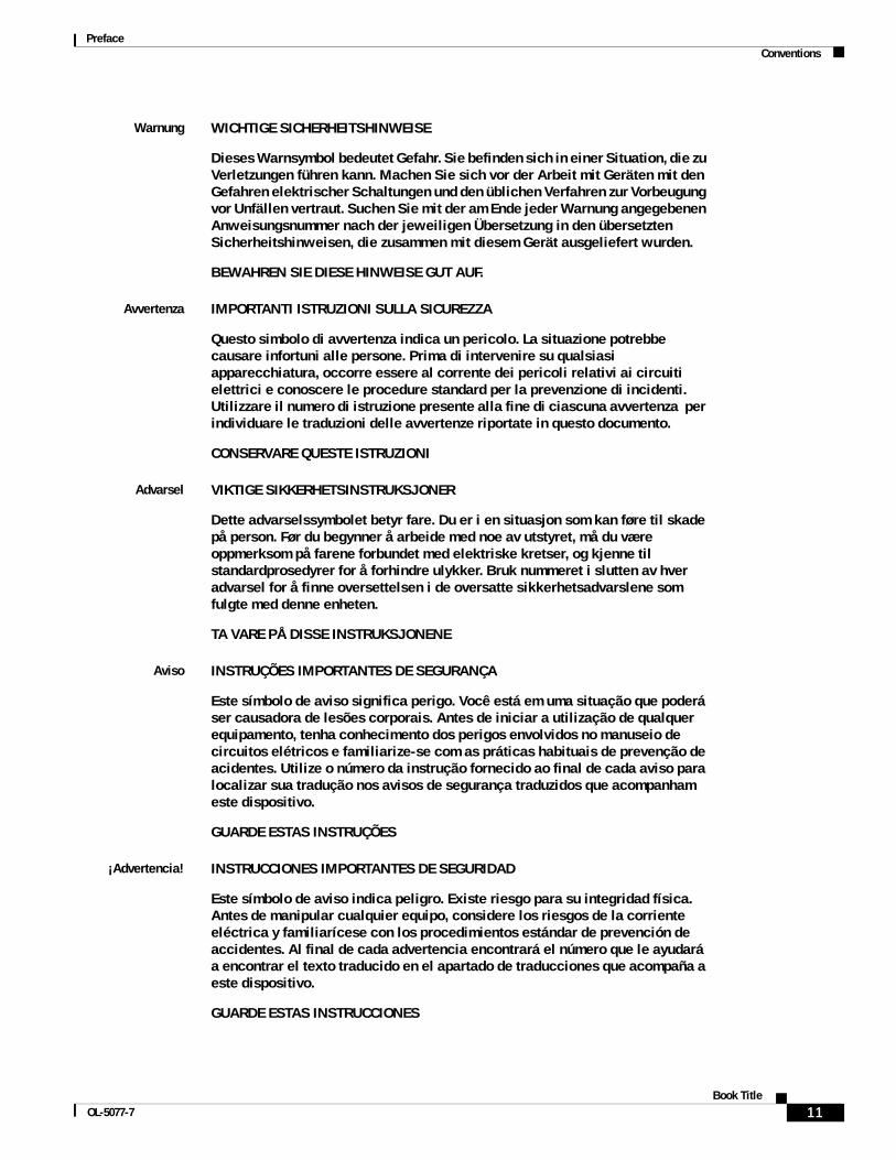
Warnung WICHTIGE SICHERHEITSHINWEISE
Dieses Warnsymbol bedeutet Gefahr. Sie befinden sich in einer Situation, die zu Verletzungen führen kann. Machen Sie sich vor der Arbeit mit Geräten mit den Gefahren elektrischer Schaltungen und den üblichen Verfahren zur Vorbeugung vor Unfällen vertraut. Suchen Sie mit der am Ende jeder Warnung angegebenen Anweisungsnummer nach der jeweiligen Übersetzung in den übersetzten Sicherheitshinweisen, die zusammen mit diesem Gerät ausgeliefert wurden.
BEWAHREN SIE DIESE HINWEISE GUT AUF.
Avvertenza IMPORTANTI ISTRUZIONI SULLA SICUREZZA
Questo simbolo di avvertenza indica un pericolo. La situazione potrebbe causare infortuni alle persone. Prima di intervenire su qualsiasi apparecchiatura, occorre essere al corrente dei pericoli relativi ai circuiti elettrici e conoscere le procedure standard per la prevenzione di incidenti. Utilizzare il numero di istruzione presente alla fine di ciascuna avvertenza per individuare le traduzioni delle avvertenze riportate in questo documento.
CONSERVARE QUESTE ISTRUZIONI
Advarsel VIKTIGE SIKKERHETSINSTRUKSJONER
Dette advarselssymbolet betyr fare. Du er i en situasjon som kan føre til skade på person. Før du begynner å arbeide med noe av utstyret, må du være oppmerksom på farene forbundet med elektriske kretser, og kjenne til standardprosedyrer for å forhindre ulykker. Bruk nummeret i slutten av hver advarsel for å finne oversettelsen i de oversatte sikkerhetsadvarslene som fulgte med denne enheten.
TA VARE PÅ DISSE INSTRUKSJONENE
Aviso INSTRUÇÕES IMPORTANTES DE SEGURANÇA
Este símbolo de aviso significa perigo. Você está em uma situação que poderá ser causadora de lesões corporais. Antes de iniciar a utilização de qualquer equipamento, tenha conhecimento dos perigos envolvidos no manuseio de circuitos elétricos e familiarize-se com as práticas habituais de prevenção de acidentes. Utilize o número da instrução fornecido ao final de cada aviso para localizar sua tradução nos avisos de segurança traduzidos que acompanham este dispositivo.
GUARDE ESTAS INSTRUÇÕES
¡Advertencia! INSTRUCCIONES IMPORTANTES DE SEGURIDAD
Este símbolo de aviso indica peligro. Existe riesgo para su integridad física. Antes de manipular cualquier equipo, considere los riesgos de la corriente eléctrica y familiarícese con los procedimientos estándar de prevención de accidentes. Al final de cada advertencia encontrará el número que le ayudará a encontrar el texto traducido en el apartado de traducciones que acompaña a este dispositivo.
GUARDE ESTAS INSTRUCCIONES
11Book Title
OL-5077-7

PrefaceConventions
Varning! VIKTIGA SÄKERHETSANVISNINGAR
Denna varningssignal signalerar fara. Du befinner dig i en situation som kan leda till personskada. Innan du utför arbete på någon utrustning måste du vara medveten om farorna med elkretsar och känna till vanliga förfaranden för att förebygga olyckor. Använd det nummer som finns i slutet av varje varning för att hitta dess översättning i de översatta säkerhetsvarningar som medföljer denna anordning.
SPARA DESSA ANVISNINGAR
12Book Title
OL-5077-7
PrefaceRelated Documentation
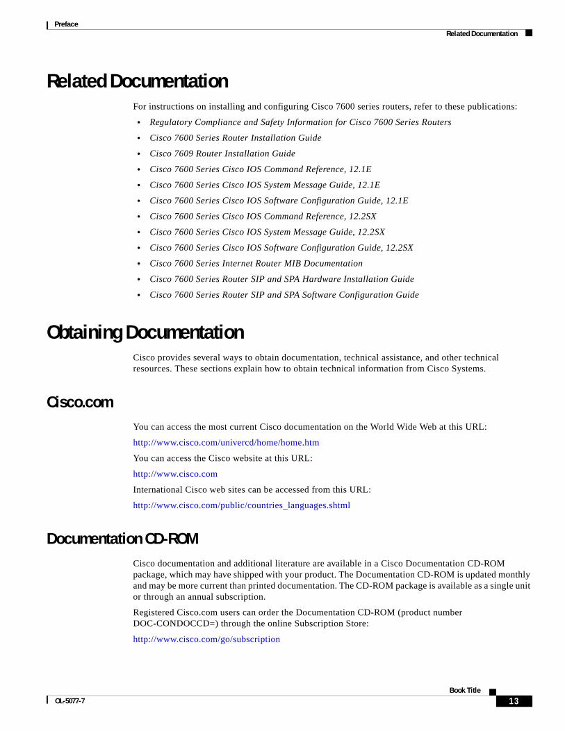
Related DocumentationFor instructions on installing and configuring Cisco 7600 series routers, refer to these publications:
• Regulatory Compliance and Safety Information for Cisco 7600 Series Routers
• Cisco 7600 Series Router Installation Guide
• Cisco 7609 Router Installation Guide
• Cisco 7600 Series Cisco IOS Command Reference, 12.1E
• Cisco 7600 Series Cisco IOS System Message Guide, 12.1E
• Cisco 7600 Series Cisco IOS Software Configuration Guide, 12.1E
• Cisco 7600 Series Cisco IOS Command Reference, 12.2SX
• Cisco 7600 Series Cisco IOS System Message Guide, 12.2SX
• Cisco 7600 Series Cisco IOS Software Configuration Guide, 12.2SX
• Cisco 7600 Series Internet Router MIB Documentation
• Cisco 7600 Series Router SIP and SPA Hardware Installation Guide
• Cisco 7600 Series Router SIP and SPA Software Configuration Guide
Obtaining DocumentationCisco provides several ways to obtain documentation, technical assistance, and other technical resources. These sections explain how to obtain technical information from Cisco Systems.
Cisco.comYou can access the most current Cisco documentation on the World Wide Web at this URL:
http://www.cisco.com/univercd/home/home.htm
You can access the Cisco website at this URL:
http://www.cisco.com
International Cisco web sites can be accessed from this URL:
http://www.cisco.com/public/countries_languages.shtml
Documentation CD-ROMCisco documentation and additional literature are available in a Cisco Documentation CD-ROM package, which may have shipped with your product. The Documentation CD-ROM is updated monthly and may be more current than printed documentation. The CD-ROM package is available as a single unit or through an annual subscription.
Registered Cisco.com users can order the Documentation CD-ROM (product number DOC-CONDOCCD=) through the online Subscription Store:
http://www.cisco.com/go/subscription
13Book Title
OL-5077-7
PrefaceObtaining Technical Assistance
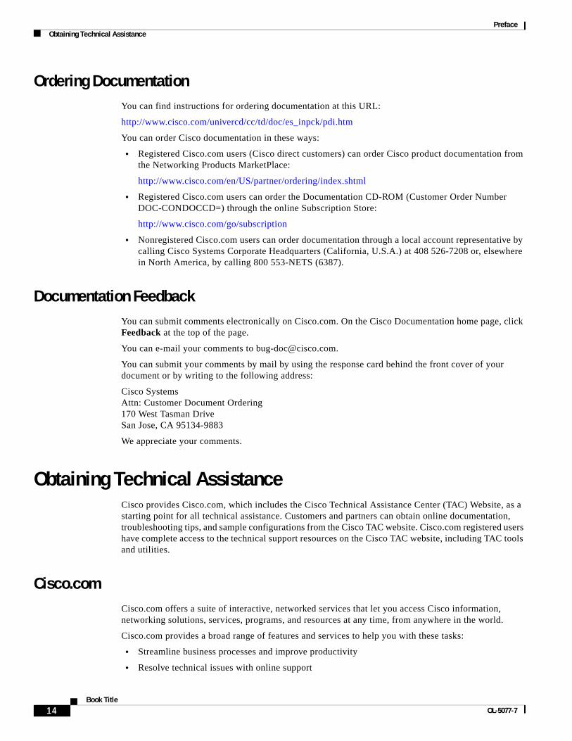
Ordering DocumentationYou can find instructions for ordering documentation at this URL:
http://www.cisco.com/univercd/cc/td/doc/es_inpck/pdi.htm
You can order Cisco documentation in these ways:
• Registered Cisco.com users (Cisco direct customers) can order Cisco product documentation from the Networking Products MarketPlace:
http://www.cisco.com/en/US/partner/ordering/index.shtml
• Registered Cisco.com users can order the Documentation CD-ROM (Customer Order Number DOC-CONDOCCD=) through the online Subscription Store:
http://www.cisco.com/go/subscription
• Nonregistered Cisco.com users can order documentation through a local account representative by calling Cisco Systems Corporate Headquarters (California, U.S.A.) at 408 526-7208 or, elsewhere in North America, by calling 800 553-NETS (6387).
Documentation FeedbackYou can submit comments electronically on Cisco.com. On the Cisco Documentation home page, click Feedback at the top of the page.
You can e-mail your comments to [email protected].
You can submit your comments by mail by using the response card behind the front cover of your document or by writing to the following address:
Cisco Systems Attn: Customer Document Ordering 170 West Tasman Drive San Jose, CA 95134-9883
We appreciate your comments.
Obtaining Technical AssistanceCisco provides Cisco.com, which includes the Cisco Technical Assistance Center (TAC) Website, as a starting point for all technical assistance. Customers and partners can obtain online documentation, troubleshooting tips, and sample configurations from the Cisco TAC website. Cisco.com registered users have complete access to the technical support resources on the Cisco TAC website, including TAC tools and utilities.
Cisco.comCisco.com offers a suite of interactive, networked services that let you access Cisco information, networking solutions, services, programs, and resources at any time, from anywhere in the world.
Cisco.com provides a broad range of features and services to help you with these tasks:
• Streamline business processes and improve productivity
• Resolve technical issues with online support
14Book Title
OL-5077-7
PrefaceObtaining Technical Assistance
• Download and test software packages
• Order Cisco learning materials and merchandise
• Register for online skill assessment, training, and certification programs
To obtain customized information and service, you can self-register on Cisco.com at this URL:
http://www.cisco.com
Technical Assistance CenterThe Cisco TAC is available to all customers who need technical assistance with a Cisco product, technology, or solution. Two levels of support are available: the Cisco TAC website and the Cisco TAC Escalation Center. The avenue of support that you choose depends on the priority of the problem and the conditions stated in service contracts, when applicable.
We categorize Cisco TAC inquiries according to urgency:
• Priority level 4 (P4)—You need information or assistance concerning Cisco product capabilities, product installation, or basic product configuration.
• Priority level 3 (P3)—Your network performance is degraded. Network functionality is noticeably impaired, but most business operations continue.
• Priority level 2 (P2)—Your production network is severely degraded, affecting significant aspects of business operations. No workaround is available.
• Priority level 1 (P1)—Your production network is down, and a critical impact to business operations will occur if service is not restored quickly. No workaround is available.
Cisco TAC Website
You can use the Cisco TAC website to resolve P3 and P4 issues yourself, saving both cost and time. The site provides around-the-clock access to online tools, knowledge bases, and software. To access the Cisco TAC website, go to this URL:
http://www.cisco.com/tac
All customers, partners, and resellers who have a valid Cisco service contract have complete access to the technical support resources on the Cisco TAC website. Some services on the Cisco TAC website require a Cisco.com login ID and password. If you have a valid service contract but do not have a login ID or password, go to this URL to register:
http://tools.cisco.com/RPF/register/register.do
If you are a Cisco.com registered user, and you cannot resolve your technical issues by using the Cisco TAC website, you can open a case online at this URL:
http://www.cisco.com/en/US/support/index.html
If you have Internet access, we recommend that you open P3 and P4 cases through the Cisco TAC website so that you can describe the situation in your own words and attach any necessary files.
15Book Title
OL-5077-7
PrefaceObtaining Additional Publications and Information
Cisco TAC Escalation Center
The Cisco TAC Escalation Center addresses priority level 1 or priority level 2 issues. These classifications are assigned when severe network degradation significantly impacts business operations. When you contact the TAC Escalation Center with a P1 or P2 problem, a Cisco TAC engineer automatically opens a case.
To obtain a directory of toll-free Cisco TAC telephone numbers for your country, go to this URL:
http://www.cisco.com/warp/public/687/Directory/DirTAC.shtml
Before calling, please check with your network operations center to determine the level of Cisco support services to which your company is entitled: for example, SMARTnet, SMARTnet Onsite, or Network Supported Accounts (NSA). When you call the center, please have available your service agreement number and your product serial number.
Obtaining Additional Publications and InformationInformation about Cisco products, technologies, and network solutions is available from various online and printed sources.
• The Cisco Product Catalog describes the networking products offered by Cisco Systems as well as ordering and customer support services. Access the Cisco Product Catalog at this URL:
http://www.cisco.com/en/US/products/products_catalog_links_launch.html
• Cisco Press publishes a wide range of networking publications. Cisco suggests these titles for new and experienced users: Internetworking Terms and Acronyms Dictionary, Internetworking Technology Handbook, Internetworking Troubleshooting Guide, and the Internetworking Design Guide. For current Cisco Press titles and other information, go to Cisco Press online at this URL:
http://www.ciscopress.com
• Packet magazine is the Cisco monthly periodical that provides industry professionals with the latest information about the field of networking. You can access Packet magazine at this URL:
http://www.cisco.com/en/US/about/ac123/ac114/about_cisco_packet_magazine.html
• iQ Magazine is the Cisco monthly periodical that provides business leaders and decision makers with the latest information about the networking industry. You can access iQ Magazine at this URL:
http://business.cisco.com/prod/tree.taf%3fasset_id=44699&public_view=true&kbns=1.html
• Internet Protocol Journal is a quarterly journal published by Cisco Systems for engineering professionals involved in the design, development, and operation of public and private internets and intranets. You can access the Internet Protocol Journal at this URL:
http://www.cisco.com/en/US/about/ac123/ac147/about_cisco_the_internet_protocol_journal.html
• Training—Cisco offers world-class networking training, with current offerings in network training listed at this URL:
http://www.cisco.com/en/US/learning/le31/learning_recommended_training_list.html
16Book Title
OL-5077-7
OL-5077-7
C H A P T E R 1
Product OverviewThis chapter describes the Cisco 7600 series routers, supervisor engines, Optical Services Modules (OSMs), recommended Catalyst 6500 family modules, Ethernet Services 20G line cards, and SPA interface processors (SIPs). It contains these sections:
• Cisco 7600 Series Routers, page 1-1
• Supervisor Engines, page 1-4
• Optical Services Modules, page 1-17
• Catalyst 6500 Family Modules, page 1-24
• SPA Interface Processors, page 1-29
• Ethernet Services 20G Line Cards, page 1-31
• Cisco 7600 Ethernet Services Plus Line Cards, page 1-33
• Hot Swapping Supervisor Engines and Modules, page 1-39
• Power Management and Environmental Monitoring, page 1-39
• OSM Technology Overview, page 1-39
Cisco 7600 Series RoutersThe Cisco 7600 series routers consist of these routers:
• Cisco 7603 router (3 slots)
• Cisco 7604 router (4 slots)
• Cisco 7606 router (6 slots)
• Cisco 7609 router (9 vertical slots)
• Cisco 7609-S router (9 vertical slots)
• Cisco 7613 router (13 slots)
Cisco 7600 series routers provide optical WAN and MAN networking with a focus on line-rate delivery of high-touch IP services at the edge of service provider networks.
Supported HardwareThe Cisco 7600 series routers support the following hardware:
1-1Book Title
Chapter 1 Product Overview Cisco 7600 Series Routers
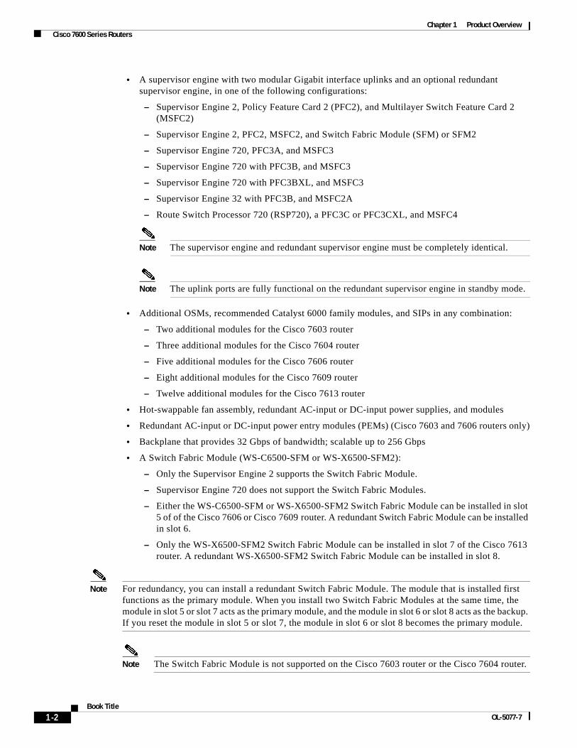
• A supervisor engine with two modular Gigabit interface uplinks and an optional redundant supervisor engine, in one of the following configurations:
– Supervisor Engine 2, Policy Feature Card 2 (PFC2), and Multilayer Switch Feature Card 2 (MSFC2)
– Supervisor Engine 2, PFC2, MSFC2, and Switch Fabric Module (SFM) or SFM2
– Supervisor Engine 720, PFC3A, and MSFC3
– Supervisor Engine 720 with PFC3B, and MSFC3
– Supervisor Engine 720 with PFC3BXL, and MSFC3
– Supervisor Engine 32 with PFC3B, and MSFC2A
– Route Switch Processor 720 (RSP720), a PFC3C or PFC3CXL, and MSFC4
Note The supervisor engine and redundant supervisor engine must be completely identical.
Note The uplink ports are fully functional on the redundant supervisor engine in standby mode.
• Additional OSMs, recommended Catalyst 6000 family modules, and SIPs in any combination:
– Two additional modules for the Cisco 7603 router
– Three additional modules for the Cisco 7604 router
– Five additional modules for the Cisco 7606 router
– Eight additional modules for the Cisco 7609 router
– Twelve additional modules for the Cisco 7613 router
• Hot-swappable fan assembly, redundant AC-input or DC-input power supplies, and modules
• Redundant AC-input or DC-input power entry modules (PEMs) (Cisco 7603 and 7606 routers only)
• Backplane that provides 32 Gbps of bandwidth; scalable up to 256 Gbps
• A Switch Fabric Module (WS-C6500-SFM or WS-X6500-SFM2):
– Only the Supervisor Engine 2 supports the Switch Fabric Module.
– Supervisor Engine 720 does not support the Switch Fabric Modules.
– Either the WS-C6500-SFM or WS-X6500-SFM2 Switch Fabric Module can be installed in slot 5 of of the Cisco 7606 or Cisco 7609 router. A redundant Switch Fabric Module can be installed in slot 6.
– Only the WS-X6500-SFM2 Switch Fabric Module can be installed in slot 7 of the Cisco 7613 router. A redundant WS-X6500-SFM2 Switch Fabric Module can be installed in slot 8.
Note For redundancy, you can install a redundant Switch Fabric Module. The module that is installed first functions as the primary module. When you install two Switch Fabric Modules at the same time, the module in slot 5 or slot 7 acts as the primary module, and the module in slot 6 or slot 8 acts as the backup. If you reset the module in slot 5 or slot 7, the module in slot 6 or slot 8 becomes the primary module.
Note The Switch Fabric Module is not supported on the Cisco 7603 router or the Cisco 7604 router.
1-2Book Title
OL-5077-7
Chapter 1 Product Overview Cisco 7600 Series Routers
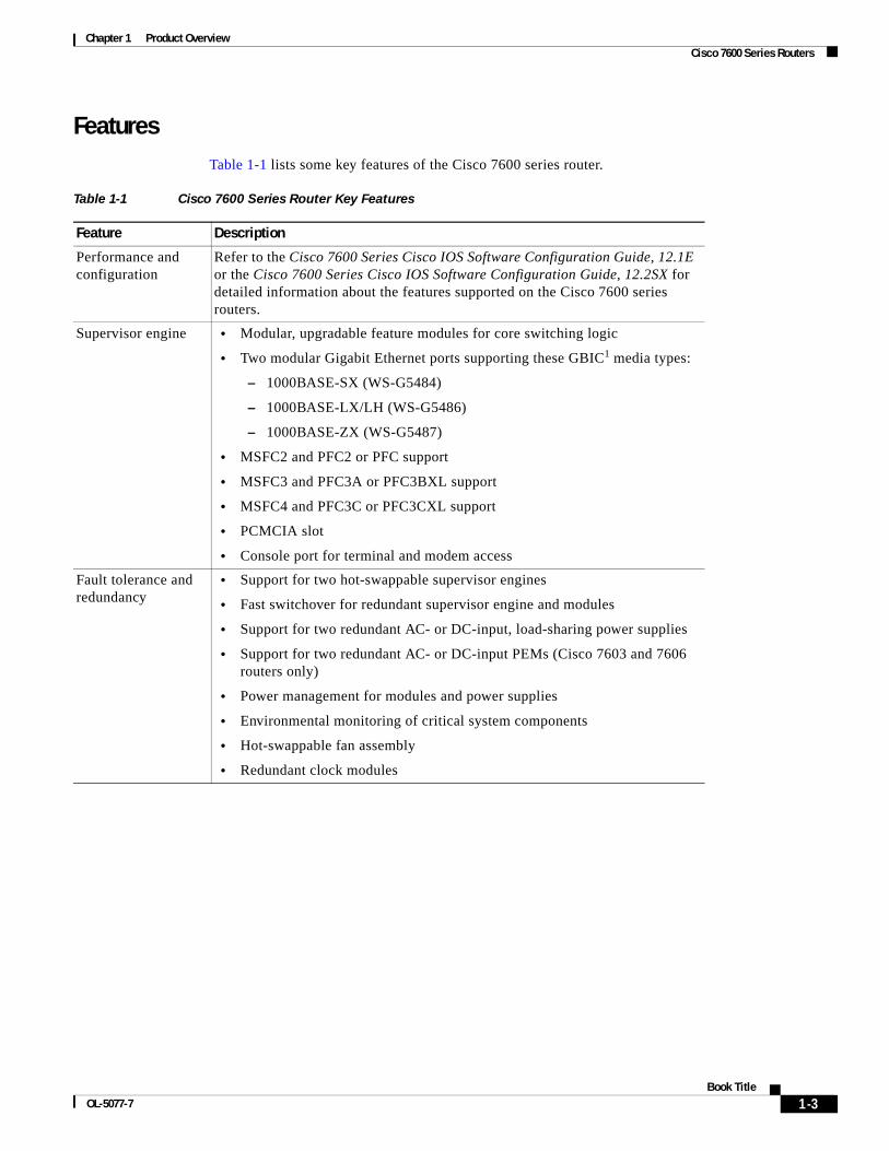
FeaturesTable 1-1 lists some key features of the Cisco 7600 series router.
Table 1-1 Cisco 7600 Series Router Key Features
Feature Description
Performance and configuration
Refer to the Cisco 7600 Series Cisco IOS Software Configuration Guide, 12.1E or the Cisco 7600 Series Cisco IOS Software Configuration Guide, 12.2SX for detailed information about the features supported on the Cisco 7600 series routers.
Supervisor engine • Modular, upgradable feature modules for core switching logic
• Two modular Gigabit Ethernet ports supporting these GBIC1 media types:
– 1000BASE-SX (WS-G5484)
– 1000BASE-LX/LH (WS-G5486)
– 1000BASE-ZX (WS-G5487)
• MSFC2 and PFC2 or PFC support
• MSFC3 and PFC3A or PFC3BXL support
• MSFC4 and PFC3C or PFC3CXL support
• PCMCIA slot
• Console port for terminal and modem access
Fault tolerance and redundancy
• Support for two hot-swappable supervisor engines
• Fast switchover for redundant supervisor engine and modules
• Support for two redundant AC- or DC-input, load-sharing power supplies
• Support for two redundant AC- or DC-input PEMs (Cisco 7603 and 7606 routers only)
• Power management for modules and power supplies
• Environmental monitoring of critical system components
• Hot-swappable fan assembly
• Redundant clock modules
1-3Book Title
OL-5077-7

Chapter 1 Product Overview Supervisor Engines
Supervisor EnginesThis section describes the features on the Supervisor Engine 2, and Supervisor Engine 720. This section contains the following topics:
• LEDs, page 1-11
• Console Port, page 1-15
• Console Port Mode Switch, page 1-15
• Switch Load Meter, page 1-16
• PCMCIA Slot, page 1-16
• Uplink Ports, page 1-16
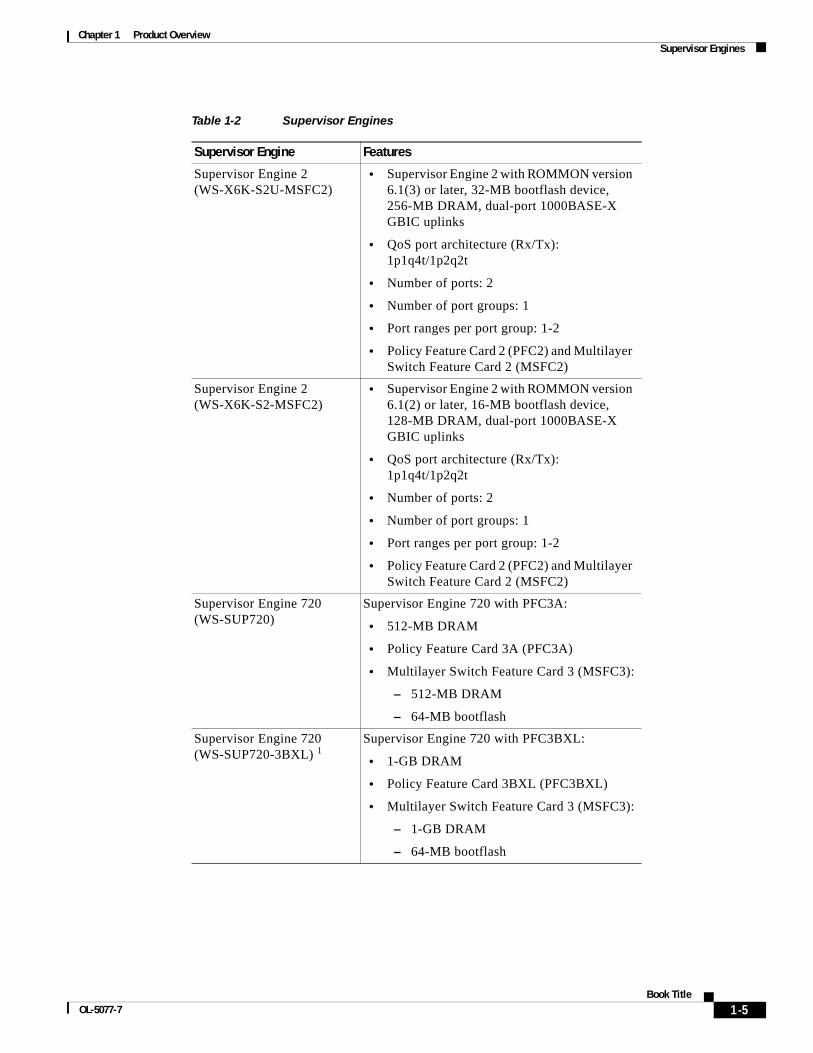
Table 1-2 lists the supervisor engine configurations.
Memory components
• 512-KB NVRAM stores configuration information.
• EEPROM2 component on the supervisor engine stores module-specific information, such as the module serial number, part number, controller type, hardware revision, configuration information, and other details unique to each module.
• 256-MB DRAM for the default system software.
• Bootflash—32-MB Flash memory stores the boot image.
• 16-MB Flash memory stores and runs software images.
• PC Flash—One slot for 16- and 24-MB Flash PC cards (cards optional). Use this additional Flash memory to store and run software images and configuration files or to serve as an I/O device.
• Flash file system—Flash memory contains a file system. You can use a variety of commands to manage the file system (such as cd, pwd, dir, and delete). The file system includes the following devices:
– Onboard bootflash
– PC Flash slot
Component hot swapping
All components (including the optional redundant supervisor engine and fans) support hot swapping, which allows you to add, replace, or remove components without interrupting the system power or causing other software or interfaces to shut down.
Management • CLI through the console port or Telnet
• Simple Network Management Protocol
1. GBIC = Gigabit Interface Converter
2. EEPROM = electrically erasable programmable read-only memory
Table 1-1 Cisco 7600 Series Router Key Features (continued)
Feature Description
1-4Book Title
OL-5077-7
Chapter 1 Product Overview Supervisor Engines
Table 1-2 Supervisor Engines
Supervisor Engine Features
Supervisor Engine 2 (WS-X6K-S2U-MSFC2)
• Supervisor Engine 2 with ROMMON version 6.1(3) or later, 32-MB bootflash device, 256-MB DRAM, dual-port 1000BASE-X GBIC uplinks
• QoS port architecture (Rx/Tx): 1p1q4t/1p2q2t
• Number of ports: 2
• Number of port groups: 1
• Port ranges per port group: 1-2
• Policy Feature Card 2 (PFC2) and Multilayer Switch Feature Card 2 (MSFC2)
Supervisor Engine 2 (WS-X6K-S2-MSFC2)
• Supervisor Engine 2 with ROMMON version 6.1(2) or later, 16-MB bootflash device, 128-MB DRAM, dual-port 1000BASE-X GBIC uplinks
• QoS port architecture (Rx/Tx): 1p1q4t/1p2q2t
• Number of ports: 2
• Number of port groups: 1
• Port ranges per port group: 1-2
• Policy Feature Card 2 (PFC2) and Multilayer Switch Feature Card 2 (MSFC2)
Supervisor Engine 720 (WS-SUP720)
Supervisor Engine 720 with PFC3A:
• 512-MB DRAM
• Policy Feature Card 3A (PFC3A)
• Multilayer Switch Feature Card 3 (MSFC3):
– 512-MB DRAM
– 64-MB bootflash
Supervisor Engine 720 (WS-SUP720-3BXL) 1
Supervisor Engine 720 with PFC3BXL:
• 1-GB DRAM
• Policy Feature Card 3BXL (PFC3BXL)
• Multilayer Switch Feature Card 3 (MSFC3):
– 1-GB DRAM
– 64-MB bootflash
1-5Book Title
OL-5077-7
Chapter 1 Product Overview Supervisor Engines
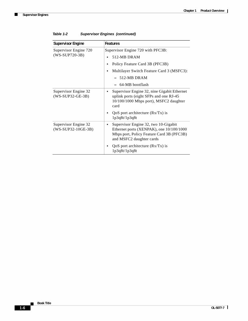
Supervisor Engine 720 (WS-SUP720-3B)
Supervisor Engine 720 with PFC3B:
• 512-MB DRAM
• Policy Feature Card 3B (PFC3B)
• Multilayer Switch Feature Card 3 (MSFC3):
– 512-MB DRAM
– 64-MB bootflash
Supervisor Engine 32 (WS-SUP32-GE-3B)
• Supervisor Engine 32, nine Gigabit Ethernet uplink ports (eight SFPs and one RJ-45 10/100/1000 Mbps port), MSFC2 daughter card
• QoS port architecture (Rx/Tx) is 1p3q8t/1p3q8t
Supervisor Engine 32 (WS-SUP32-10GE-3B)
• Supervisor Engine 32, two 10-Gigabit Ethernet ports (XENPAK), one 10/100/1000 Mbps port, Policy Feature Card 3B (PFC3B) and MSFC2 daughter cards
• QoS port architecture (Rx/Tx) is 1p3q8t/1p3q8t
Table 1-2 Supervisor Engines (continued)
Supervisor Engine Features
1-6Book Title
OL-5077-7
Chapter 1 Product Overview Supervisor Engines
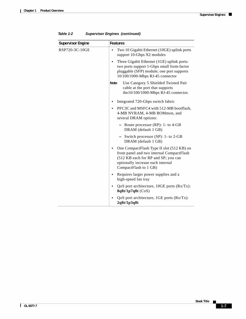
RSP720-3C-10GE • Two 10 Gigabit Ethernet (10GE) uplink ports support 10-Gbps X2 modules
• Three Gigabit Ethernet (1GE) uplink ports: two ports support 1-Gbps small form-factor pluggable (SFP) module; one port supports 10/100/1000-Mbps RJ-45 connector
Note Use Category 5 Shielded Twisted Pair cable at the port that supports the10/100/1000-Mbps RJ-45 connector.
• Integrated 720-Gbps switch fabric
• PFC3C and MSFC4 with 512-MB bootflash, 4-MB NVRAM, 4-MB ROMmon, and several DRAM options:
– Route processor (RP): 1- to 4-GB DRAM (default 1 GB)
– Switch processor (SP): 1- to 2-GB DRAM (default 1 GB)
• One CompactFlash Type II slot (512 KB) on front panel and two internal CompactFlash (512 KB each for RP and SP; you can optionally increase each internal CompactFlash to 1 GB)
• Requires larger power supplies and a high-speed fan tray
• QoS port architecture, 10GE ports (Rx/Tx): 8q8t/1p7q8t (CoS)
• QoS port architecture, 1GE ports (Rx/Tx): 2q8t/1p3q8t
Table 1-2 Supervisor Engines (continued)
Supervisor Engine Features
1-7Book Title
OL-5077-7
Chapter 1 Product Overview Supervisor Engines
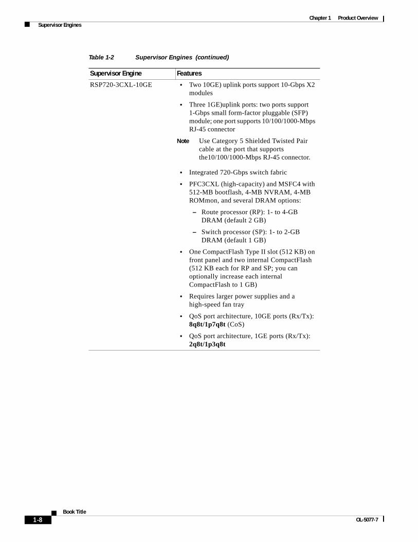
RSP720-3CXL-10GE • Two 10GE) uplink ports support 10-Gbps X2 modules
• Three 1GE)uplink ports: two ports support 1-Gbps small form-factor pluggable (SFP) module; one port supports 10/100/1000-Mbps RJ-45 connector
Note Use Category 5 Shielded Twisted Pair cable at the port that supports the10/100/1000-Mbps RJ-45 connector.
• Integrated 720-Gbps switch fabric
• PFC3CXL (high-capacity) and MSFC4 with 512-MB bootflash, 4-MB NVRAM, 4-MB ROMmon, and several DRAM options:
– Route processor (RP): 1- to 4-GB DRAM (default 2 GB)
– Switch processor (SP): 1- to 2-GB DRAM (default 1 GB)
• One CompactFlash Type II slot (512 KB) on front panel and two internal CompactFlash (512 KB each for RP and SP; you can optionally increase each internal CompactFlash to 1 GB)
• Requires larger power supplies and a high-speed fan tray
• QoS port architecture, 10GE ports (Rx/Tx): 8q8t/1p7q8t (CoS)
• QoS port architecture, 1GE ports (Rx/Tx): 2q8t/1p3q8t
Table 1-2 Supervisor Engines (continued)
Supervisor Engine Features
1-8Book Title
OL-5077-7
Chapter 1 Product Overview Supervisor Engines
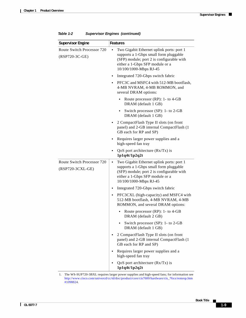
Route Switch Processor 720
(RSP720-3C-GE)
• Two Gigabit Ethernet uplink ports: port 1 supports a 1-Gbps small form pluggable (SFP) module; port 2 is configurable with either a 1-Gbps SFP module or a 10/100/1000-Mbps RJ-45
• Integrated 720-Gbps switch fabric
• PFC3C and MSFC4 with 512-MB bootflash, 4-MB NVRAM, 4-MB ROMMON, and several DRAM options:
• Route processor (RP): 1- to 4-GB DRAM (default 1 GB)
• Switch processor (SP): 1- to 2-GB DRAM (default 1 GB)
• 2 CompactFlash Type II slots (on front panel) and 2-GB internal CompactFlash (1 GB each for RP and SP)
• Requires larger power supplies and a high-speed fan tray
• QoS port architecture (Rx/Tx) is 1p1q4t/1p2q2t
Route Switch Processor 720
(RSP720-3CXL-GE)
• Two Gigabit Ethernet uplink ports: port 1 supports a 1-Gbps small form pluggable (SFP) module; port 2 is configurable with either a 1-Gbps SFP module or a 10/100/1000-Mbps RJ-45
• Integrated 720-Gbps switch fabric
• PFC3CXL (high-capacity) and MSFC4 with 512-MB bootflash, 4-MB NVRAM, 4-MB ROMMON, and several DRAM options:
• Route processor (RP): 1- to 4-GB DRAM (default 2 GB)
• Switch processor (SP): 1- to 2-GB DRAM (default 1 GB)
• 2 CompactFlash Type II slots (on front panel) and 2-GB internal CompactFlash (1 GB each for RP and SP)
• Requires larger power supplies and a high-speed fan tray
• QoS port architecture (Rx/Tx) is 1p1q4t/1p2q2t
1. The WS-SUP720-3BXL requires larger power supplies and high-speed fans; for information see http://www.cisco.com/univercd/cc/td/doc/product/core/cis7600/hardware/cis_76xx/remrep.htm#1098824.
Table 1-2 Supervisor Engines (continued)
Supervisor Engine Features
1-9Book Title
OL-5077-7

Chapter 1 Product Overview Supervisor Engines
Figure 1-1 shows the front panel features of the Supervisor Engine 2. Figure 1-2 shows the front-panel features of the Supervisor Engine 720. Figure 1-3 show the front-panel features of the Supervisor Engine 32 (WS-SUP32-GE-3B). Figure 1-4 show the front-panel features of the Supervisor Engine 32 (WS-SUP32-10GE-3B).
Figure 1-1 Supervisor Engine 2 Front Panel Features
Figure 1-2 Supervisor Engine 720 Front Panel Features
Figure 1-3 Supervisor Engine 32 (WS-SUP32-GE-3B) Front Panel Features44
312
SUPERVISOR2
WS-X6K-SUP2-2GE
STATUS
SYSTEM
CONSOLE
PWR M
GMT
RESET
CONSOLE
CONSOLEPORTMODE
PCMCIA EJECT
PORT 1 PORT 2
Switch Load 100%
1%
LINK
LINK
PCMCIA LED
LINK LEDs
StatusLEDs
RESET button
CONSOLE port
CONSOLE PORTMODE switch PCMCIA slot
1000BASE-X GBIC Uplink Ports
Switch loaddisplay
8789
0
STATUS LEDs
Disk LEDs
CONSOLE port
LINK LEDs
Gigabit Ethernetuplink port
10/100/1000 uplink port
CompactFlashType II slots
1206
90
CONSOLE port
CompactFlashType II slot
Status LEDs
RESET button
Uplink ports
USB portsLink Status LEDs
Disk LED
Uplink port
1-10Book Title
OL-5077-7
Chapter 1 Product Overview Supervisor Engines
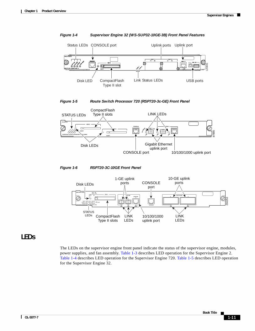
Figure 1-4 Supervisor Engine 32 (WS-SUP32-10GE-3B) Front Panel Features
Figure 1-5 Route Switch Processor 720 (RSP720-3c-GE) Front Panel
Figure 1-6 RSP720-3C-10GE Front Panel
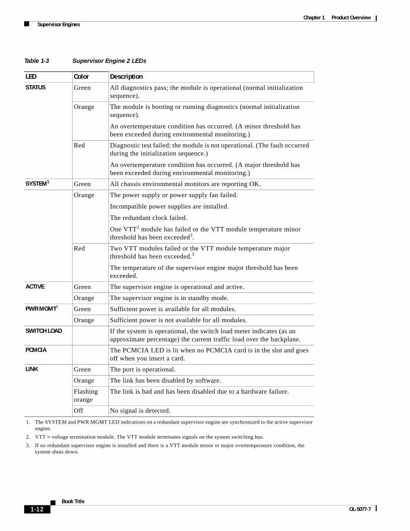
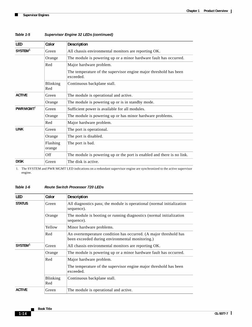
LEDsThe LEDs on the supervisor engine front panel indicate the status of the supervisor engine, modules, power supplies, and fan assembly. Table 1-3 describes LED operation for the Supervisor Engine 2. Table 1-4 describes LED operation for the Supervisor Engine 720. Table 1-5 describes LED operation for the Supervisor Engine 32.
1206
91
CONSOLE port
CompactFlashType II slot
Status LEDs Uplink ports
USB portsLink Status LEDsDisk LED
Uplink port
8789
0
STATUS LEDs
Disk LEDs
CONSOLE port
LINK LEDs
Gigabit Ethernetuplink port
10/100/1000 uplink port
CompactFlashType II slots
RSP720-3C-10GE
STATUS SYSTEM ACTIVE PWR MGMT
RESET
EJECT
DISK 0UPLINK
SFP1 3
10/100/1003
LINK LINKLINKCONSOLE
LINKLINK
410GE UPLINK
5
RSP720 WITH INTERATED SWITCH FABRIC/PFC3C-10GE 2502
53
Disk LEDs
LINKLEDs
STATUSLEDs CompactFlash
Type II slots
1-GE uplinkports CONSOLE
port
10/100/1000uplink port
10-GE uplinkports
LINKLEDs
1-11Book Title
OL-5077-7
Chapter 1 Product Overview Supervisor Engines
Table 1-3 Supervisor Engine 2 LEDs
LED Color Description
STATUS Green All diagnostics pass; the module is operational (normal initialization sequence).
Orange The module is booting or running diagnostics (normal initialization sequence).
An overtemperature condition has occurred. (A minor threshold has been exceeded during environmental monitoring.)
Red Diagnostic test failed; the module is not operational. (The fault occurred during the initialization sequence.)
An overtemperature condition has occurred. (A major threshold has been exceeded during environmental monitoring.)
SYSTEM1
1. The SYSTEM and PWR MGMT LED indications on a redundant supervisor engine are synchronized to the active supervisor engine.
Green All chassis environmental monitors are reporting OK.
Orange The power supply or power supply fan failed.
Incompatible power supplies are installed.
The redundant clock failed.
One VTT2 module has failed or the VTT module temperature minor threshold has been exceeded3.
2. VTT = voltage termination module. The VTT module terminates signals on the system switching bus.
3. If no redundant supervisor engine is installed and there is a VTT module minor or major overtemperature condition, the system shuts down.
Red Two VTT modules failed or the VTT module temperature major threshold has been exceeded.3
The temperature of the supervisor engine major threshold has been exceeded.
ACTIVE Green The supervisor engine is operational and active.
Orange The supervisor engine is in standby mode.
PWR MGMT1 Green Sufficient power is available for all modules.
Orange Sufficient power is not available for all modules.
SWITCH LOAD If the system is operational, the switch load meter indicates (as an approximate percentage) the current traffic load over the backplane.
PCMCIA The PCMCIA LED is lit when no PCMCIA card is in the slot and goes off when you insert a card.
LINK Green The port is operational.
Orange The link has been disabled by software.
Flashing orange
The link is bad and has been disabled due to a hardware failure.
Off No signal is detected.
1-12Book Title
OL-5077-7

Chapter 1 Product Overview Supervisor Engines
Table 1-4 Supervisor Engine 720 LEDs
LED Color Description
STATUS Green All diagnostics pass; the module is operational (normal initialization sequence).
Orange The module is booting or running diagnostics (normal initialization sequence).
Yellow Minor hardware problems.
Red An overtemperature condition has occurred. (A major threshold has been exceeded during environmental monitoring.)
SYSTEM1
1. The SYSTEM and PWR MGMT LED indications on a redundant supervisor engine are synchronized to the active supervisor engine.
Green All chassis environmental monitors are reporting OK.
Orange The module is powering up or a minor hardware fault has occurred.
Red Major hardware problem.
The temperature of the supervisor engine major threshold has been exceeded.
Blinking Red
Continuous backplane stall.
ACTIVE Green The module is operational and active.
Orange The module is powering up or is in standby mode.
PWR MGMT1 Green Sufficient power is available for all modules.
Orange The module is powering up or has minor hardware problems.
Red Major hardware problem.
LINK Green The port is operational.
Orange The port is disabled.
Flashing orange
The port is bad.
Off The module is powering up or the port is enabled and there is no link.
DISK 0 Green The disk is active.
DISK 1 Green The disk is active.
Table 1-5 Supervisor Engine 32 LEDs
LED Color Description
STATUS Green All diagnostics pass; the module is operational (normal initialization sequence).
Orange The module is booting or running diagnostics (normal initialization sequence).
Yellow Minor hardware problems.
Red An overtemperature condition has occurred. (A major threshold has been exceeded during environmental monitoring.)
1-13Book Title
OL-5077-7
Chapter 1 Product Overview Supervisor Engines
SYSTEM1 Green All chassis environmental monitors are reporting OK.
Orange The module is powering up or a minor hardware fault has occurred.
Red Major hardware problem.
The temperature of the supervisor engine major threshold has been exceeded.
Blinking Red
Continuous backplane stall.
ACTIVE Green The module is operational and active.
Orange The module is powering up or is in standby mode.
PWR MGMT1 Green Sufficient power is available for all modules.
Orange The module is powering up or has minor hardware problems.
Red Major hardware problem.
LINK Green The port is operational.
Orange The port is disabled.
Flashing orange
The port is bad.
Off The module is powering up or the port is enabled and there is no link.
DISK Green The disk is active.
1. The SYSTEM and PWR MGMT LED indications on a redundant supervisor engine are synchronized to the active supervisor engine.
Table 1-6 Route Switch Processor 720 LEDs
LED Color Description
STATUS Green All diagnostics pass; the module is operational (normal initialization sequence).
Orange The module is booting or running diagnostics (normal initialization sequence).
Yellow Minor hardware problems.
Red An overtemperature condition has occurred. (A major threshold has been exceeded during environmental monitoring.)
SYSTEM1 Green All chassis environmental monitors are reporting OK.
Orange The module is powering up or a minor hardware fault has occurred.
Red Major hardware problem.
The temperature of the supervisor engine major threshold has been exceeded.
Blinking Red
Continuous backplane stall.
ACTIVE Green The module is operational and active.
Table 1-5 Supervisor Engine 32 LEDs (continued)
LED Color Description
1-14Book Title
OL-5077-7

Chapter 1 Product Overview Supervisor Engines
Reset ButtonThe Reset button allows you to restart the system.
Note Use a ballpoint pen tip or other small, pointed object to access the Reset button.
Console PortThe console port allows you to access the system either locally (with a console terminal) or remotely (with a modem). The console port is an EIA/TIA-232 asynchronous, serial connection with hardware flow control and an RJ-45 connector.
Note EIA/TIA-232 and EIA/TIA-449 were known as recommended standards RS-232 and RS-449 before their acceptance as standards by the Electronic Industries Alliance (EIA) and Telecommunications Industry Association (TIA).
For detailed information on using this port, see the “Connecting to the Console Port” section on page 3-15.
Console Port Mode SwitchThe console port mode switch allows you to connect a terminal to the supervisor engine using either the console cable and adapters provided with the Cisco 7600 series routers or the console cable provided with a Catalyst 5000 family Supervisor Engine III.
You also can connect a modem to the console port using the cable and adapter provided with the system.
Orange The module is powering up or is in standby mode.
PWR MGMT1 Green Sufficient power is available for all modules.
Orange The module is powering up or has minor hardware problems.
Red Major hardware problem.
LINK Green The port is operational.
Orange The port is disabled.
Flashing orange
The port is bad.
Off The module is powering up or the port is enabled and there is no link.
DISK Green The disk is active.
1. The SYSTEM and PWR MGMT LED indications on a redundant supervisor engine are synchronized to the active supervisor engine.
Table 1-6 Route Switch Processor 720 LEDs (continued)
LED Color Description
1-15Book Title
OL-5077-7
Chapter 1 Product Overview Supervisor Engines
Note To access the port mode switch, use a ballpoint pen tip or other small, pointed object.
To connect a terminal, use the port mode switch as follows:
• Mode 1—Switch in the in position (factory default). Use this mode to connect a terminal to the console port using the console cable and DTE adapter (labeled “Terminal”) that shipped with the system.
You can also use this mode to connect a modem to the console port using the console cable and DCE adapter (labeled “Modem”) that shipped with the system.
• Mode 2—Switch in the out position. Use this mode to connect a terminal to the console port using the Catalyst 5000 family Supervisor Engine III console cable (not provided).
For more information on using the console port, see the “Connecting to the Console Port” section on page 3-15.
Switch Load MeterThe switch load meter provides you with a visual approximation of the current traffic load across the backplane.
PCMCIA SlotThe Flash PC card (PCMCIA card) slot holds a Flash PC card for additional Flash memory. You can use this Flash memory to store and run software images or to serve as an I/O device.
Note Throughout this publication, the term Flash PC card is used in place of the term PCMCIA card.
For detailed information on using the Flash PC card, see the “Using Flash PC Cards” section on page 3-20.
Uplink PortsThe supervisor engine provides two Gigabit Ethernet uplink ports that you can configure with any combination of short-wave (SX), long-wave/long-haul (LX/LH), and extended reach (ZX) Gigabit Interface Converters (GBICs). The two 1000BASE-X Gigabit Ethernet uplink ports operate in full-duplex mode only.
Note In a redundant configuration with two supervisor engines, the uplink ports on the redundant (standby) supervisor engine are active and can be used for normal traffic like any other ports in the chassis.
For detailed information on these ports, see the “Connecting to the Uplink Ports” section on page 3-16.
1-16Book Title
OL-5077-7
Chapter 1 Product Overview Optical Services Modules
Optical Services ModulesThis section describes the Optical Services Modules (OSMs). This section is divided into the following topics:
• OC-3c POS OSM, page 1-17
• OC-12c POS OSM, page 1-18
• OC-48 POS OSM, page 1-18
• OC-48 DPT/POS OSM, page 1-19
• Channelized OC-12 OSM, page 1-19
• OC-12 ATM OSM, page 1-20
• 2+4-Port Gigabit Ethernet WAN OSM, page 1-20
• 12-Port Channelized T3 OSM, page 1-20
• OSM LED Descriptions, page 1-21
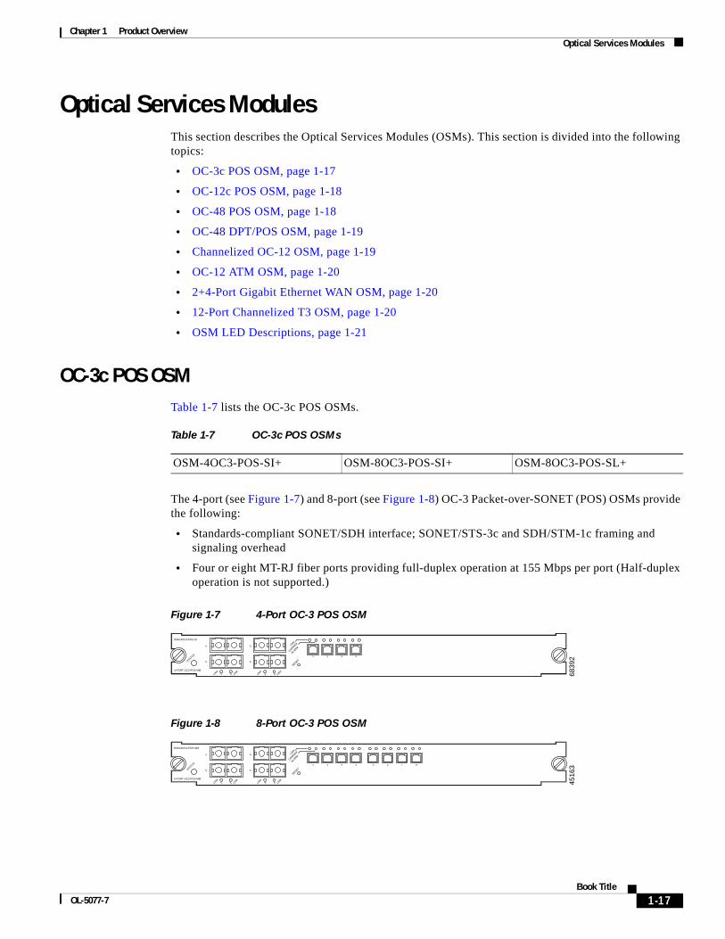
OC-3c POS OSMTable 1-7 lists the OC-3c POS OSMs.
The 4-port (see Figure 1-7) and 8-port (see Figure 1-8) OC-3 Packet-over-SONET (POS) OSMs provide the following:
• Standards-compliant SONET/SDH interface; SONET/STS-3c and SDH/STM-1c framing and signaling overhead
• Four or eight MT-RJ fiber ports providing full-duplex operation at 155 Mbps per port (Half-duplex operation is not supported.)
Figure 1-7 4-Port OC-3 POS OSM
Figure 1-8 8-Port OC-3 POS OSM
Table 1-7 OC-3c POS OSMs
OSM-4OC3-POS-SI+ OSM-8OC3-POS-SI+ OSM-8OC3-POS-SL+
6839
2
4 PORT OC3 POS MM
OSM-4OC3-POS SI
STATUS
1
1
2
2
3
3
1 2 3 4
4
4
RESET
LINK
CARRIER
ALARM
LINK
LINK
LINK
LINK
4516
3
8 PORT OC3 POS MM
OSM-8OC3-POS MM
STATUS
1
1
2
2
3
3
1 2 3 4
4
4
RESET
LINK
CARRIER
ALARM
LINK
LINK
LINK
LINK
5 6 7 8
1-17Book Title
OL-5077-7
Chapter 1 Product Overview Optical Services Modules
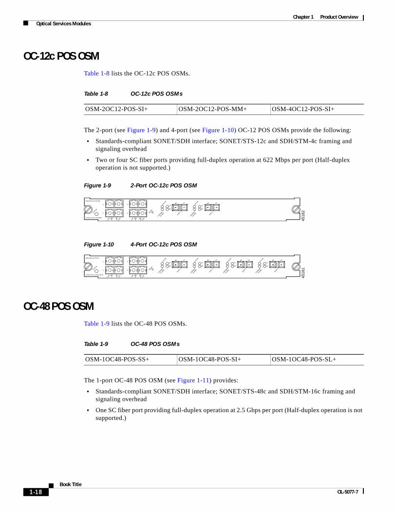
OC-12c POS OSMTable 1-8 lists the OC-12c POS OSMs.
The 2-port (see Figure 1-9) and 4-port (see Figure 1-10) OC-12 POS OSMs provide the following:
• Standards-compliant SONET/SDH interface; SONET/STS-12c and SDH/STM-4c framing and signaling overhead
• Two or four SC fiber ports providing full-duplex operation at 622 Mbps per port (Half-duplex operation is not supported.)
Figure 1-9 2-Port OC-12c POS OSM
Figure 1-10 4-Port OC-12c POS OSM
OC-48 POS OSMTable 1-9 lists the OC-48 POS OSMs.
The 1-port OC-48 POS OSM (see Figure 1-11) provides:
• Standards-compliant SONET/SDH interface; SONET/STS-48c and SDH/STM-16c framing and signaling overhead
• One SC fiber port providing full-duplex operation at 2.5 Gbps per port (Half-duplex operation is not supported.)
Table 1-8 OC-12c POS OSMs
OSM-2OC12-POS-SI+ OSM-2OC12-POS-MM+ OSM-4OC12-POS-SI+
4516
2
2 PORT OC-12 POS MM
OSM-2OC12-POS MM
STATUS
1
1
2
2
3
3
4
4
RESET
LINK
LINK
LINK
LINK
CARRIER
ALARM
ACTIVE
TXRX TX
PORT 1
RX
CARRIER
ALARM
ACTIVE
TXRX TX
PORT 2
RX
4516
1
4 PORT OC-12 POS SM IR
OSM-4OC12 POS-SI
STATUS
1
1
2
2
3
3
4
4
RESET
LINK
LINK
LINK
LINK
CARRIER
ALARM
CARRIER
ALARM
CARRIER
ALARM
CARRIER
ALARM
ACTIVE
TXRX TX
PORT 1
RX
ACTIVE
TXRX TX
PORT 2
RX
ACTIVE
TXRX TX
PORT 3
RX
ACTIVE
TXRX TX
PORT4
RX
Table 1-9 OC-48 POS OSMs
OSM-1OC48-POS-SS+ OSM-1OC48-POS-SI+ OSM-1OC48-POS-SL+
1-18Book Title
OL-5077-7
Chapter 1 Product Overview Optical Services Modules
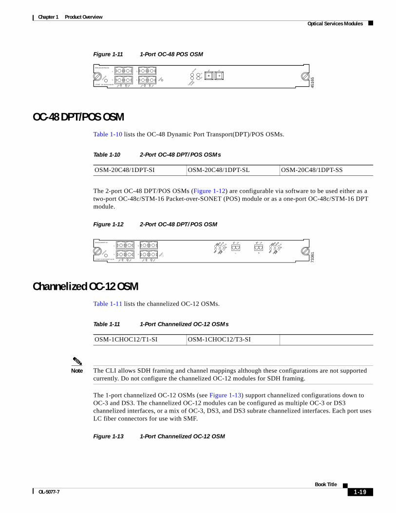
Figure 1-11 1-Port OC-48 POS OSM
OC-48 DPT/POS OSMTable 1-10 lists the OC-48 Dynamic Port Transport(DPT)/POS OSMs.
The 2-port OC-48 DPT/POS OSMs (Figure 1-12) are configurable via software to be used either as a two-port OC-48c/STM-16 Packet-over-SONET (POS) module or as a one-port OC-48c/STM-16 DPT module.
Figure 1-12 2-Port OC-48 DPT/POS OSM
Channelized OC-12 OSMTable 1-11 lists the channelized OC-12 OSMs.
Note The CLI allows SDH framing and channel mappings although these configurations are not supported currently. Do not configure the channelized OC-12 modules for SDH framing.
The 1-port channelized OC-12 OSMs (see Figure 1-13) support channelized configurations down to OC-3 and DS3. The channelized OC-12 modules can be configured as multiple OC-3 or DS3 channelized interfaces, or a mix of OC-3, DS3, and DS3 subrate channelized interfaces. Each port uses LC fiber connectors for use with SMF.
Figure 1-13 1-Port Channelized OC-12 OSM
4516
5
1 PORT OC-48 POS SM SR
OSM-1OC48-POS-SS
STATUS
1
1
2
2
3
3
4
4LINK
LINK
LINK
LINK
RESET
CARRIER
ALARM
ACTIVE
TX
RX TX
RX
Table 1-10 2-Port OC-48 DPT/POS OSMs
OSM-20C48/1DPT-SI OSM-20C48/1DPT-SL OSM-20C48/1DPT-SS
7336
1
2 PORT OC48 POS/DPT SN SR
OSM-20C48/IDPT-SS
STATUS
RESET
1
1
2
2
3
3
4
4LINK
LINK
LINK
LINK
Table 1-11 1-Port Channelized OC-12 OSMs
OSM-1CHOC12/T1-SI OSM-1CHOC12/T3-SI
1-19Book Title
OL-5077-7
Chapter 1 Product Overview Optical Services Modules
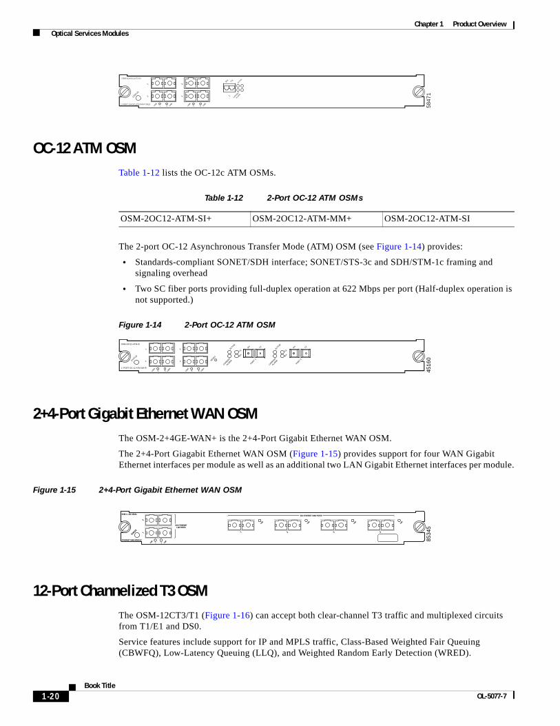
OC-12 ATM OSMTable 1-12 lists the OC-12c ATM OSMs.
Table 1-12 2-Port OC-12 ATM OSMs
The 2-port OC-12 Asynchronous Transfer Mode (ATM) OSM (see Figure 1-14) provides:
• Standards-compliant SONET/SDH interface; SONET/STS-3c and SDH/STM-1c framing and signaling overhead
• Two SC fiber ports providing full-duplex operation at 622 Mbps per port (Half-duplex operation is not supported.)
Figure 1-14 2-Port OC-12 ATM OSM
2+4-Port Gigabit Ethernet WAN OSMThe OSM-2+4GE-WAN+ is the 2+4-Port Gigabit Ethernet WAN OSM.
The 2+4-Port Giagabit Ethernet WAN OSM (Figure 1-15) provides support for four WAN Gigabit Ethernet interfaces per module as well as an additional two LAN Gigabit Ethernet interfaces per module.
Figure 1-15 2+4-Port Gigabit Ethernet WAN OSM
12-Port Channelized T3 OSMThe OSM-12CT3/T1 (Figure 1-16) can accept both clear-channel T3 traffic and multiplexed circuits from T1/E1 and DS0.
Service features include support for IP and MPLS traffic, Class-Based Weighted Fair Queuing (CBWFQ), Low-Latency Queuing (LLQ), and Weighted Random Early Detection (WRED).
5847
1
OSM-1CHOC12/T3-SI
1 PORT CHOC12/STM4/T3/E3
STATUS
ACTIVE
CARRIER
ALARM1
TXRX
1
1
2
2
3
3
4
4LINK
LINK
LINK
LINK
OSM-2OC12-ATM-SI+ OSM-2OC12-ATM-MM+ OSM-2OC12-ATM-SI
4516
0
2 PORT OC-12 ATM SM IR
OSM-20C12-ATM-SI
STATUS
1
2
3
4
4321
RESET
LINK
LINK
LINK
LINK
CARRIER
ALARM
CARRIER
ALARM
ACTIVE
TXRX TX
PORT 1
RX
ACTIVE
TXRX TX
PORT 2
RX
8534
5
1-20Book Title
OL-5077-7
Chapter 1 Product Overview Optical Services Modules
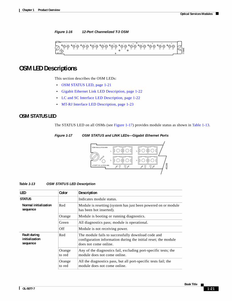
Figure 1-16 12-Port Channelized T-3 OSM
OSM LED DescriptionsThis section describes the OSM LEDs:
• OSM STATUS LED, page 1-21
• Gigabit Ethernet Link LED Description, page 1-22
• LC and SC Interface LED Description, page 1-22
• MT-RJ Interface LED Description, page 1-23
OSM STATUS LED
The STATUS LED on all OSMs (see Figure 1-17) provides module status as shown in Table 1-13.
Figure 1-17 OSM STATUS and LINK LEDs—Gigabit Ethernet Ports
7788
6Table 1-13 OSM STATUS LED Description
LED Color Description
STATUS Indicates module status.
Normal initialization sequence
Red Module is resetting (system has just been powered on or module has been hot inserted).
Orange Module is booting or running diagnostics.
Green All diagnostics pass; module is operational.
Off Module is not receiving power.
Fault during initialization sequence
Red The module fails to successfully download code and configuration information during the initial reset; the module does not come online.
Orange to red
Any of the diagnostics fail, excluding port-specific tests; the module does not come online.
Orange to red
All the diagnostics pass, but all port-specific tests fail; the module does not come online.
4516
64 PORT OC-12 POS MM
OSM-4OC12-POS-MM
STATUS
1
1
2
2
3
3
4
4LINK
LINK
LINK
LINK
1-21Book Title
OL-5077-7
Chapter 1 Product Overview Optical Services Modules
Gigabit Ethernet Link LED Description
The GBIC-based Gigabit Ethernet LINK LEDs (see Figure 1-17) are described in Table 1-14.
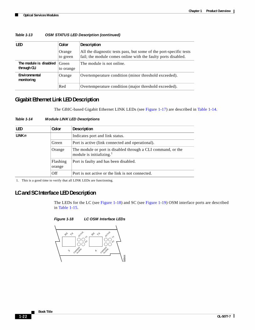
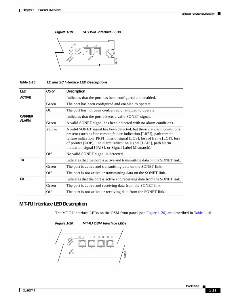
LC and SC Interface LED Description
The LEDs for the LC (see Figure 1-18) and SC (see Figure 1-19) OSM interface ports are described in Table 1-15.
Figure 1-18 LC OSM Interface LEDs
Orange to green
All the diagnostic tests pass, but some of the port-specific tests fail; the module comes online with the faulty ports disabled.
The module is disabled through CLI
Green to orange
The module is not online.
Environmental monitoring
Orange Overtemperature condition (minor threshold exceeded).
Red Overtemperature condition (major threshold exceeded).
Table 1-13 OSM STATUS LED Description (continued)
LED Color Description
Table 1-14 Module LINK LED Descriptions
LED Color Description
LINK n Indicates port and link status.
Green Port is active (link connected and operational).
Orange The module or port is disabled through a CLI command, or the module is initializing.1
1. This is a good time to verify that all LINK LEDs are functioning.
Flashing orange
Port is faulty and has been disabled.
Off Port is not active or the link is not connected.
5894
4
ACTIVE
TX
RX
CARRIER
ALARM
4
TXRXACTIV
E
TX
RX
CARRIER
ALARM
3
TXRX
1-22Book Title
OL-5077-7
Chapter 1 Product Overview Optical Services Modules
Figure 1-19 SC OSM Interface LEDs
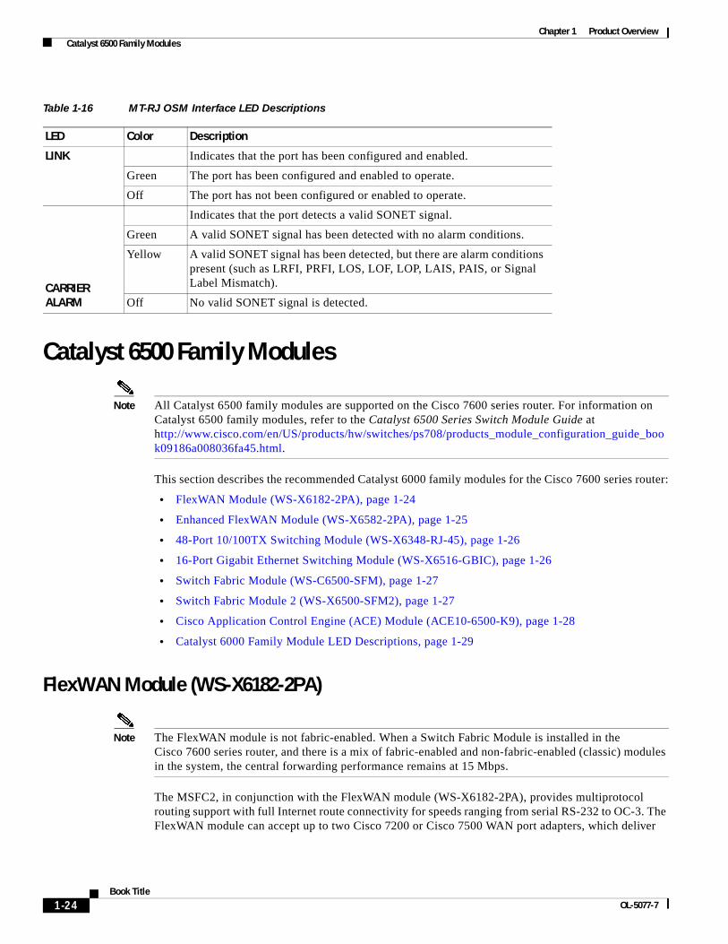
MT-RJ Interface LED Description
The MT-RJ interface LEDs on the OSM front panel (see Figure 1-20) are described in Table 1-16.
Figure 1-20 MT-RJ OSM Interface LEDs
Table 1-15 LC and SC Interface LED Descriptions
LED Color Description
ACTIVE Indicates that the port has been configured and enabled.
Green The port has been configured and enabled to operate.
Off The port has not been configured or enabled to operate.
CARRIER ALARM
Indicates that the port detects a valid SONET signal.
Green A valid SONET signal has been detected with no alarm conditions.
Yellow A valid SONET signal has been detected, but there are alarm conditions present (such as line remote failure indication [LRFI], path remote failure indication [PRFI], loss of signal [LOS], loss of frame [LOF], loss of pointer [LOP], line alarm indication signal [LAIS], path alarm indication signal [PAIS], or Signal Label Mismatch).
Off No valid SONET signal is detected.
TX Indicates that the port is active and transmitting data on the SONET link.
Green The port is active and transmitting data on the SONET link.
Off The port is not active or transmitting data on the SONET link.
RX Indicates that the port is active and receiving data from the SONET link.
Green The port is active and receiving data from the SONET link.
Off The port is not active or receiving data from the SONET link.
5574
9
CARRIER
ALARM
ACTIVE
TXRX TX
PORT4
RX
5575
0
1 2 3 4
RESET
LINK
CARRIER
ALARM
1-23Book Title
OL-5077-7
Chapter 1 Product Overview Catalyst 6500 Family Modules
Catalyst 6500 Family Modules
Note All Catalyst 6500 family modules are supported on the Cisco 7600 series router. For information on Catalyst 6500 family modules, refer to the Catalyst 6500 Series Switch Module Guide at http://www.cisco.com/en/US/products/hw/switches/ps708/products_module_configuration_guide_book09186a008036fa45.html.
This section describes the recommended Catalyst 6000 family modules for the Cisco 7600 series router:
• FlexWAN Module (WS-X6182-2PA), page 1-24
• Enhanced FlexWAN Module (WS-X6582-2PA), page 1-25
• 48-Port 10/100TX Switching Module (WS-X6348-RJ-45), page 1-26
• 16-Port Gigabit Ethernet Switching Module (WS-X6516-GBIC), page 1-26
• Switch Fabric Module (WS-C6500-SFM), page 1-27
• Switch Fabric Module 2 (WS-X6500-SFM2), page 1-27
• Cisco Application Control Engine (ACE) Module (ACE10-6500-K9), page 1-28
• Catalyst 6000 Family Module LED Descriptions, page 1-29
FlexWAN Module (WS-X6182-2PA)
Note The FlexWAN module is not fabric-enabled. When a Switch Fabric Module is installed in the Cisco 7600 series router, and there is a mix of fabric-enabled and non-fabric-enabled (classic) modules in the system, the central forwarding performance remains at 15 Mbps.
The MSFC2, in conjunction with the FlexWAN module (WS-X6182-2PA), provides multiprotocol routing support with full Internet route connectivity for speeds ranging from serial RS-232 to OC-3. The FlexWAN module can accept up to two Cisco 7200 or Cisco 7500 WAN port adapters, which deliver
Table 1-16 MT-RJ OSM Interface LED Descriptions
LED Color Description
LINK Indicates that the port has been configured and enabled.
Green The port has been configured and enabled to operate.
Off The port has not been configured or enabled to operate.
CARRIER ALARM
Indicates that the port detects a valid SONET signal.
Green A valid SONET signal has been detected with no alarm conditions.
Yellow A valid SONET signal has been detected, but there are alarm conditions present (such as LRFI, PRFI, LOS, LOF, LOP, LAIS, PAIS, or Signal Label Mismatch).
Off No valid SONET signal is detected.
1-24Book Title
OL-5077-7
Chapter 1 Product Overview Catalyst 6500 Family Modules
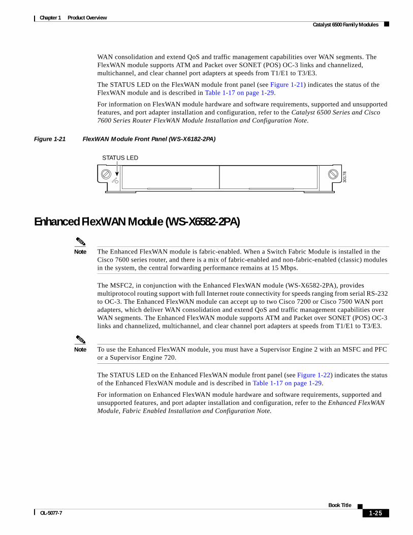
WAN consolidation and extend QoS and traffic management capabilities over WAN segments. The FlexWAN module supports ATM and Packet over SONET (POS) OC-3 links and channelized, multichannel, and clear channel port adapters at speeds from T1/E1 to T3/E3.
The STATUS LED on the FlexWAN module front panel (see Figure 1-21) indicates the status of the FlexWAN module and is described in Table 1-17 on page 1-29.
For information on FlexWAN module hardware and software requirements, supported and unsupported features, and port adapter installation and configuration, refer to the Catalyst 6500 Series and Cisco 7600 Series Router FlexWAN Module Installation and Configuration Note.
Figure 1-21 FlexWAN Module Front Panel (WS-X6182-2PA)
Enhanced FlexWAN Module (WS-X6582-2PA)
Note The Enhanced FlexWAN module is fabric-enabled. When a Switch Fabric Module is installed in the Cisco 7600 series router, and there is a mix of fabric-enabled and non-fabric-enabled (classic) modules in the system, the central forwarding performance remains at 15 Mbps.
The MSFC2, in conjunction with the Enhanced FlexWAN module (WS-X6582-2PA), provides multiprotocol routing support with full Internet route connectivity for speeds ranging from serial RS-232 to OC-3. The Enhanced FlexWAN module can accept up to two Cisco 7200 or Cisco 7500 WAN port adapters, which deliver WAN consolidation and extend QoS and traffic management capabilities over WAN segments. The Enhanced FlexWAN module supports ATM and Packet over SONET (POS) OC-3 links and channelized, multichannel, and clear channel port adapters at speeds from T1/E1 to T3/E3.
Note To use the Enhanced FlexWAN module, you must have a Supervisor Engine 2 with an MSFC and PFC or a Supervisor Engine 720.
The STATUS LED on the Enhanced FlexWAN module front panel (see Figure 1-22) indicates the status of the Enhanced FlexWAN module and is described in Table 1-17 on page 1-29.
For information on Enhanced FlexWAN module hardware and software requirements, supported and unsupported features, and port adapter installation and configuration, refer to the Enhanced FlexWAN Module, Fabric Enabled Installation and Configuration Note.
STATUS
3017
8
STATUS LED
1-25Book Title
OL-5077-7
Chapter 1 Product Overview Catalyst 6500 Family Modules
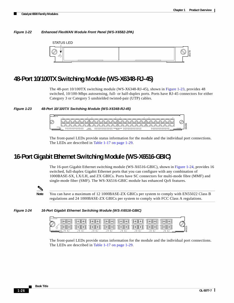
Figure 1-22 Enhanced FlexWAN Module Front Panel (WS-X6582-2PA)
48-Port 10/100TX Switching Module (WS-X6348-RJ-45) The 48-port 10/100TX switching module (WS-X6348-RJ-45), shown in Figure 1-23, provides 48 switched, 10/100-Mbps autosensing, full- or half-duplex ports. Ports have RJ-45 connectors for either Category 3 or Category 5 unshielded twisted-pair (UTP) cables.
Figure 1-23 48-Port 10/100TX Switching Module (WS-X6348-RJ-45)
The front-panel LEDs provide status information for the module and the individual port connections. The LEDs are described in Table 1-17 on page 1-29.
16-Port Gigabit Ethernet Switching Module (WS-X6516-GBIC)The 16-port Gigabit Ethernet switching module (WS-X6516-GBIC), shown in Figure 1-24, provides 16 switched, full-duplex Gigabit Ethernet ports that you can configure with any combination of 1000BASE-SX, LX/LH, and ZX GBICs. Ports have SC connectors for multi-mode fibre (MMF) and single-mode fiber (SMF). The WS-X6516-GBIC module has enhanced QoS features.
Note You can have a maximum of 12 1000BASE-ZX GBICs per system to comply with EN55022 Class B regulations and 24 1000BASE-ZX GBICs per system to comply with FCC Class A regulations.
Figure 1-24 16-Port Gigabit Ethernet Switching Module (WS-X6516-GBIC)
The front-panel LEDs provide status information for the module and the individual port connections. The LEDs are described in Table 1-17 on page 1-29.
STATUS
3017
8
STATUS LED
3949
6
48 PORT10/100 BASE-T
STATUS
ETHERNET SWITCHINGMODULE
WS-X6348-RJ-45
1 2 3 4 5 6 7 8 9 10 11 12 13 14 15 16 17 18 19 20 21 22 23 24 25 26 27 28 29 30 31 32 33 34 35 36 37 38 39 40 41 42 43 44 45 46 47 48
12 12 14 24 26 36 38 48
PHONE
4431
5
16 PORT GIGABIT ETHERNET
WS-X6516-GBIC
2STATUS
LINK
LINK
1
1 2
4
LINK
LINK
3
3 4
6
LINK
LINK
5
5 6
8
LINK
LINK
7
7 8
10
LINK
LINK
9
9 10
12
LINK
LINK
11
11 12
14
LINK
LINK
13
13 14
16
LINK
LINK
15
15 16
1-26Book Title
OL-5077-7
Chapter 1 Product Overview Catalyst 6500 Family Modules
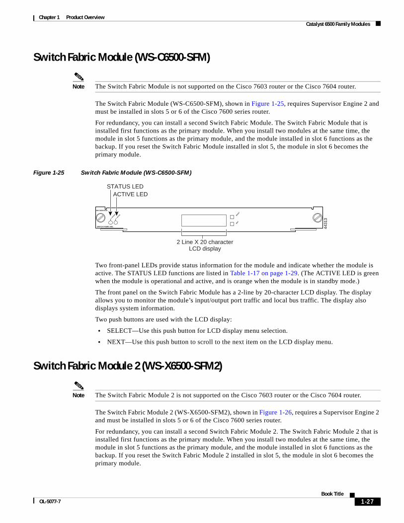
Switch Fabric Module (WS-C6500-SFM)
Note The Switch Fabric Module is not supported on the Cisco 7603 router or the Cisco 7604 router.
The Switch Fabric Module (WS-C6500-SFM), shown in Figure 1-25, requires Supervisor Engine 2 and must be installed in slots 5 or 6 of the Cisco 7600 series router.
For redundancy, you can install a second Switch Fabric Module. The Switch Fabric Module that is installed first functions as the primary module. When you install two modules at the same time, the module in slot 5 functions as the primary module, and the module installed in slot 6 functions as the backup. If you reset the Switch Fabric Module installed in slot 5, the module in slot 6 becomes the primary module.
Figure 1-25 Switch Fabric Module (WS-C6500-SFM)
Two front-panel LEDs provide status information for the module and indicate whether the module is active. The STATUS LED functions are listed in Table 1-17 on page 1-29. (The ACTIVE LED is green when the module is operational and active, and is orange when the module is in standby mode.)
The front panel on the Switch Fabric Module has a 2-line by 20-character LCD display. The display allows you to monitor the module’s input/output port traffic and local bus traffic. The display also displays system information.
Two push buttons are used with the LCD display:
• SELECT—Use this push button for LCD display menu selection.
• NEXT—Use this push button to scroll to the next item on the LCD display menu.
Switch Fabric Module 2 (WS-X6500-SFM2)
Note The Switch Fabric Module 2 is not supported on the Cisco 7603 router or the Cisco 7604 router.
The Switch Fabric Module 2 (WS-X6500-SFM2), shown in Figure 1-26, requires a Supervisor Engine 2 and must be installed in slots 5 or 6 of the Cisco 7600 series router.
For redundancy, you can install a second Switch Fabric Module 2. The Switch Fabric Module 2 that is installed first functions as the primary module. When you install two modules at the same time, the module in slot 5 functions as the primary module, and the module installed in slot 6 functions as the backup. If you reset the Switch Fabric Module 2 installed in slot 5, the module in slot 6 becomes the primary module.
4431
3
SWITCH FABRIC MDL
STATUS
SELECT
NEXT
WS-C6500-SFM
ACTIVE
STATUS LEDACTIVE LED
2 Line X 20 characterLCD display
1-27Book Title
OL-5077-7
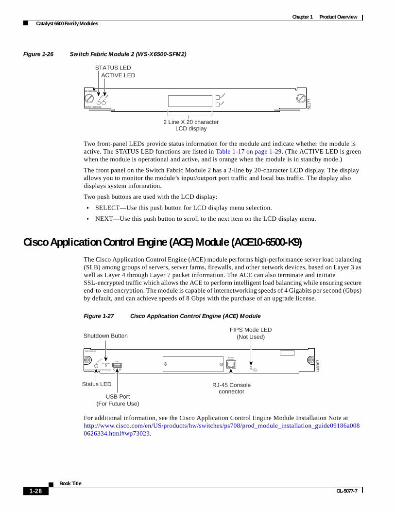
Chapter 1 Product Overview Catalyst 6500 Family Modules
Figure 1-26 Switch Fabric Module 2 (WS-X6500-SFM2)
Two front-panel LEDs provide status information for the module and indicate whether the module is active. The STATUS LED functions are listed in Table 1-17 on page 1-29. (The ACTIVE LED is green when the module is operational and active, and is orange when the module is in standby mode.)
The front panel on the Switch Fabric Module 2 has a 2-line by 20-character LCD display. The display allows you to monitor the module’s input/outport port traffic and local bus traffic. The display also displays system information.
Two push buttons are used with the LCD display:
• SELECT—Use this push button for LCD display menu selection.
• NEXT—Use this push button to scroll to the next item on the LCD display menu.
Cisco Application Control Engine (ACE) Module (ACE10-6500-K9)The Cisco Application Control Engine (ACE) module performs high-performance server load balancing (SLB) among groups of servers, server farms, firewalls, and other network devices, based on Layer 3 as well as Layer 4 through Layer 7 packet information. The ACE can also terminate and initiate SSL-encrypted traffic which allows the ACE to perform intelligent load balancing while ensuring secure end-to-end encryption. The module is capable of internetworking speeds of 4 Gigabits per second (Gbps) by default, and can achieve speeds of 8 Gbps with the purchase of an upgrade license.
Figure 1-27 Cisco Application Control Engine (ACE) Module
For additional information, see the Cisco Application Control Engine Module Installation Note at http://www.cisco.com/en/US/products/hw/switches/ps708/prod_module_installation_guide09186a0080626334.html#wp73023.
5117
7
SWITCH FABRIC MDL
STATUS
SELECT
NEXT
WS-X6500-SFMIA
ACTIVE
STATUS LEDACTIVE LED
2 Line X 20 characterLCD display
Shutdown Button
1483
67
ACE10-6500-K9
APPLICATION CONTROL ENGINE SERVICE MODULE
SHUTDOWNUSBSTA
TUSMODULE
CONSOLE
FIPSMODE
Status LED
USB Port(For Future Use)
RJ-45 Consoleconnector
FIPS Mode LED(Not Used)
1-28Book Title
OL-5077-7
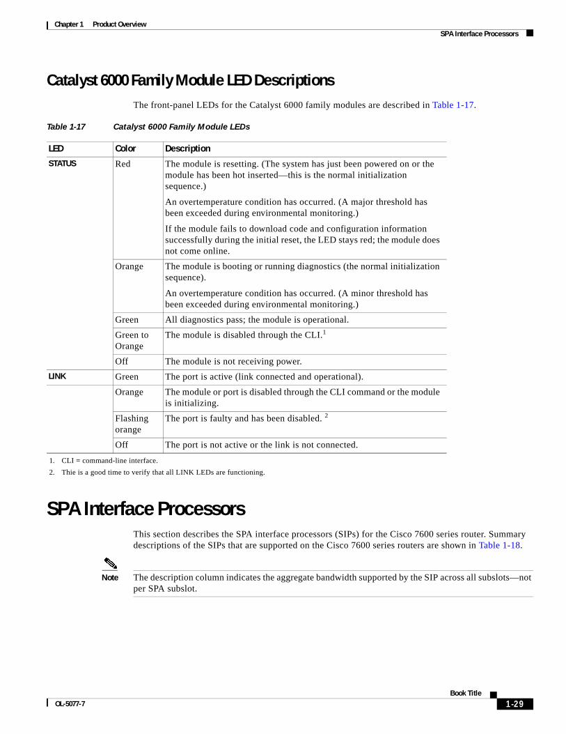
Chapter 1 Product Overview SPA Interface Processors
Catalyst 6000 Family Module LED DescriptionsThe front-panel LEDs for the Catalyst 6000 family modules are described in Table 1-17.
SPA Interface ProcessorsThis section describes the SPA interface processors (SIPs) for the Cisco 7600 series router. Summary descriptions of the SIPs that are supported on the Cisco 7600 series routers are shown in Table 1-18.
Note The description column indicates the aggregate bandwidth supported by the SIP across all subslots—not per SPA subslot.
Table 1-17 Catalyst 6000 Family Module LEDs
LED Color Description
STATUS Red The module is resetting. (The system has just been powered on or the module has been hot inserted—this is the normal initialization sequence.)
An overtemperature condition has occurred. (A major threshold has been exceeded during environmental monitoring.)
If the module fails to download code and configuration information successfully during the initial reset, the LED stays red; the module does not come online.
Orange The module is booting or running diagnostics (the normal initialization sequence).
An overtemperature condition has occurred. (A minor threshold has been exceeded during environmental monitoring.)
Green All diagnostics pass; the module is operational.
Green to Orange
The module is disabled through the CLI.1
1. CLI = command-line interface.
Off The module is not receiving power.
LINK Green The port is active (link connected and operational).
Orange The module or port is disabled through the CLI command or the module is initializing.
Flashing orange
The port is faulty and has been disabled. 2
2. Thie is a good time to verify that all LINK LEDs are functioning.
Off The port is not active or the link is not connected.
1-29Book Title
OL-5077-7
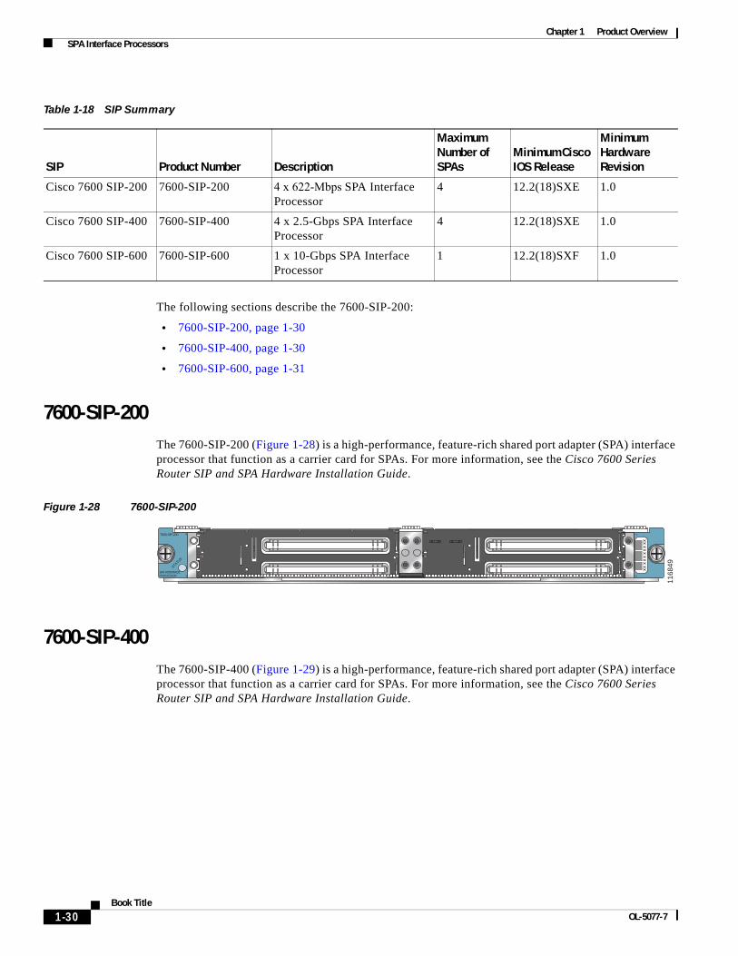
Chapter 1 Product Overview SPA Interface Processors
The following sections describe the 7600-SIP-200:
• 7600-SIP-200, page 1-30
• 7600-SIP-400, page 1-30
• 7600-SIP-600, page 1-31
7600-SIP-200The 7600-SIP-200 (Figure 1-28) is a high-performance, feature-rich shared port adapter (SPA) interface processor that function as a carrier card for SPAs. For more information, see the Cisco 7600 Series Router SIP and SPA Hardware Installation Guide.
Figure 1-28 7600-SIP-200
7600-SIP-400The 7600-SIP-400 (Figure 1-29) is a high-performance, feature-rich shared port adapter (SPA) interface processor that function as a carrier card for SPAs. For more information, see the Cisco 7600 Series Router SIP and SPA Hardware Installation Guide.
Table 1-18 SIP Summary
SIP Product Number Description
Maximum Number of SPAs
Minimum Cisco IOS Release
Minimum Hardware Revision
Cisco 7600 SIP-200 7600-SIP-200 4 x 622-Mbps SPA Interface Processor
4 12.2(18)SXE 1.0
Cisco 7600 SIP-400 7600-SIP-400 4 x 2.5-Gbps SPA Interface Processor
4 12.2(18)SXE 1.0
Cisco 7600 SIP-600 7600-SIP-600 1 x 10-Gbps SPA Interface Processor
1 12.2(18)SXF 1.0
STATUS
2
0
3
1
SPA INTERFACEPROCESSOR
7600-SIP-200
1168
49
1-30Book Title
OL-5077-7
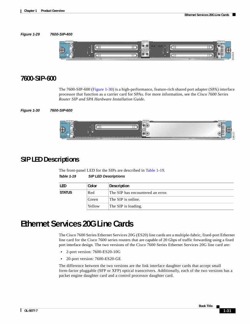
Chapter 1 Product Overview Ethernet Services 20G Line Cards
Figure 1-29 7600-SIP-400
7600-SIP-600The 7600-SIP-600 (Figure 1-30) is a high-performance, feature-rich shared port adapter (SPA) interface processor that function as a carrier card for SPAs. For more information, see the Cisco 7600 Series Router SIP and SPA Hardware Installation Guide.
Figure 1-30 7600-SIP-600
SIP LED DescriptionsThe front-panel LED for the SIPs are described in Table 1-19.
Ethernet Services 20G Line CardsThe Cisco 7600 Series Ethernet Services 20G (ES20) line cards are a multiple-fabric, fixed-port Ethernet line card for the Cisco 7600 series routers that are capable of 20 Gbps of traffic forwarding using a fixed port interface design. The two versions of the Cisco 7600 Series Ethernet Services 20G line card are:
• 2-port version: 7600-ES20-10G
• 20-port version: 7600-ES20-GE
The difference between the two versions are the link interface daughter cards that accept small form-factor pluggable (SFP or XFP) optical transceivers. Additionally, each of the two versions has a packet engine daughter card and a control processor daughter card.
STATUS
2
0
3
1
SPA INTERFACEPROCESSOR
7600-SIP-400
1013
13
STATUS
2
0
3
1
SPA INTERFACEPROCESSOR
7600-SIP-600
1381
27
Table 1-19 SIP LED Descriptions
LED Color Description
STATUS Red The SIP has encountered an error.
Green The SIP is online.
Yellow The SIP is loading.
1-31Book Title
OL-5077-7

Chapter 1 Product Overview Ethernet Services 20G Line Cards
7600-ES20-10G The Cisco7600-ES20-10G line card has three LEDs, as shown in Figure 1-31. There is one Status LED and two A/L (Active Loopback) LEDs. Table 1-21 provides LED descriptions.
Figure 1-31 Cisco 7600-ES20-10G Faceplate
There is one line card Status LED and two port Status LEDs. Table 1-21 provides LED descriptions.
Table 1-20 Cisco 7600 ES20 Line Card Summary
Cisco ES20 Line Card Product Numbers Description
Maximum Number of SFPs or XFPs
Minimum Cisco IOS Release
7600-ES20-10G 7600-ES20-10G3C, 7600-ES20-10G3CXL
2-port 10 Gigabit Ethernet line card providing core-facing redundant 10 Gigabit Ethernet uplinks with H-VPLS support.
2 Cisco IOS Release 12.2SRB
7600-ES20-GE 7600-ES20-GE3C, 7600-ES20-GE3CXL
20-port 1 Gigabit Ethernet line card providing core-facing redundant 10 Gigabit Ethernet uplinks with H-VPLS support.
20 Cisco IOS Release 12.2SRB
A/L
STATU
S
ETHERNETSERVICES MODULE
7600-ES20-10G3CXL
CLASS 1 LASER
A/L
1 0
1912
17
Table 1-21 Cisco 7600-ES20-10G LEDs
LED Label Color State Meaning
STATUS Red On The line card has encountered an error.
Green On The line card is online.
Yellow On The line card is loading.
Off Off The line card is powered off.
A/L Amber On The port is enabled but there is not a valid Ethernet link.
Green On The port is enabled and a valid Ethernet link has been established.
Green and Amber
On Undefined condition.
Off Off The port is not enabled by software.
1-32Book Title
OL-5077-7
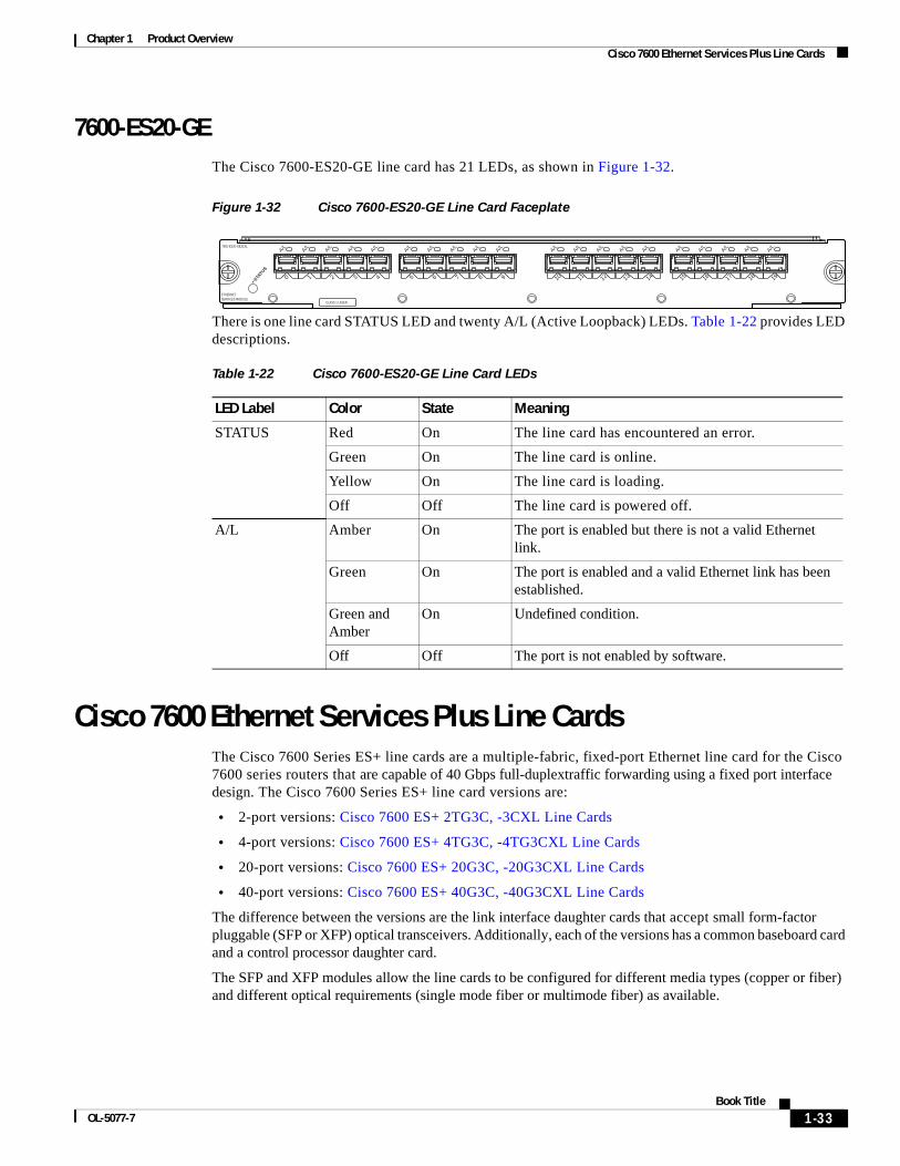
Chapter 1 Product Overview Cisco 7600 Ethernet Services Plus Line Cards
7600-ES20-GEThe Cisco 7600-ES20-GE line card has 21 LEDs, as shown in Figure 1-32.
Figure 1-32 Cisco 7600-ES20-GE Line Card Faceplate
There is one line card STATUS LED and twenty A/L (Active Loopback) LEDs. Table 1-22 provides LED descriptions.
Cisco 7600 Ethernet Services Plus Line CardsThe Cisco 7600 Series ES+ line cards are a multiple-fabric, fixed-port Ethernet line card for the Cisco 7600 series routers that are capable of 40 Gbps full-duplextraffic forwarding using a fixed port interface design. The Cisco 7600 Series ES+ line card versions are:
• 2-port versions: Cisco 7600 ES+ 2TG3C, -3CXL Line Cards
• 4-port versions: Cisco 7600 ES+ 4TG3C, -4TG3CXL Line Cards
• 20-port versions: Cisco 7600 ES+ 20G3C, -20G3CXL Line Cards
• 40-port versions: Cisco 7600 ES+ 40G3C, -40G3CXL Line Cards
The difference between the versions are the link interface daughter cards that accept small form-factor pluggable (SFP or XFP) optical transceivers. Additionally, each of the versions has a common baseboard card and a control processor daughter card.
The SFP and XFP modules allow the line cards to be configured for different media types (copper or fiber) and different optical requirements (single mode fiber or multimode fiber) as available.
STATU
S
ETHERNETSERVICES MODULE
7600-ES20-GE3CXL
CLASS 1 LASER
0A/L
1912
18
1
A/L
2
A/L
3
A/L
4
A/L
5
A/L
6
A/L
7
A/L
8
A/L
9
A/L
10
A/L
11
A/L
12
A/L
13
A/L
14
A/L
15
A/L
16
A/L
17
A/L
18
A/L
19
A/L
Table 1-22 Cisco 7600-ES20-GE Line Card LEDs
LED Label Color State Meaning
STATUS Red On The line card has encountered an error.
Green On The line card is online.
Yellow On The line card is loading.
Off Off The line card is powered off.
A/L Amber On The port is enabled but there is not a valid Ethernet link.
Green On The port is enabled and a valid Ethernet link has been established.
Green and Amber
On Undefined condition.
Off Off The port is not enabled by software.
1-33Book Title
OL-5077-7
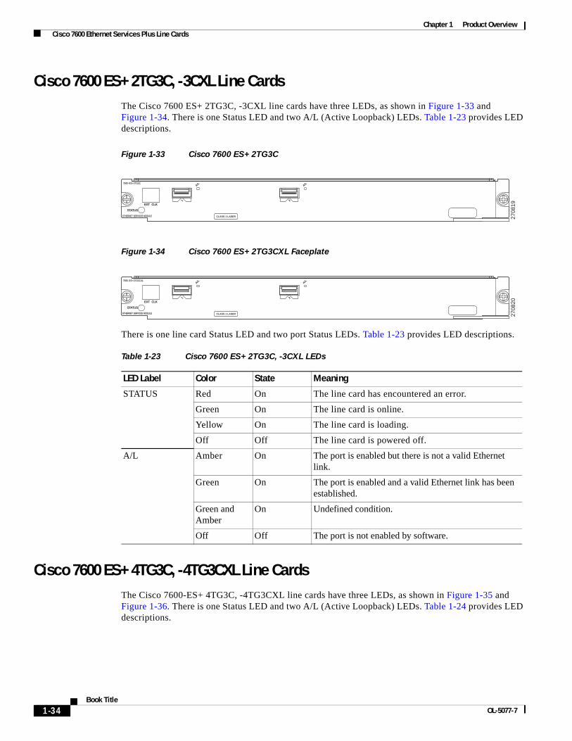
Chapter 1 Product Overview Cisco 7600 Ethernet Services Plus Line Cards
Cisco 7600 ES+ 2TG3C, -3CXL Line CardsThe Cisco 7600 ES+ 2TG3C, -3CXL line cards have three LEDs, as shown in Figure 1-33 and Figure 1-34. There is one Status LED and two A/L (Active Loopback) LEDs. Table 1-23 provides LED descriptions.
Figure 1-33 Cisco 7600 ES+ 2TG3C
Figure 1-34 Cisco 7600 ES+ 2TG3CXL Faceplate
There is one line card Status LED and two port Status LEDs. Table 1-23 provides LED descriptions.
Cisco 7600 ES+ 4TG3C, -4TG3CXL Line CardsThe Cisco 7600-ES+ 4TG3C, -4TG3CXL line cards have three LEDs, as shown in Figure 1-35 and Figure 1-36. There is one Status LED and two A/L (Active Loopback) LEDs. Table 1-24 provides LED descriptions.
7600-ES+ 2TG3C
ETHERNET SERVICES MODULE
STATUS
EXT CLK
CLASS 1 LASER 2708
19
A/L
1
A/L
2
7600-ES+ 2TG3CXL
ETHERNET SERVICES MODULE
STATUS
EXT CLK
CLASS 1 LASER 2708
20
A/L
1
A/L
2
Table 1-23 Cisco 7600 ES+ 2TG3C, -3CXL LEDs
LED Label Color State Meaning
STATUS Red On The line card has encountered an error.
Green On The line card is online.
Yellow On The line card is loading.
Off Off The line card is powered off.
A/L Amber On The port is enabled but there is not a valid Ethernet link.
Green On The port is enabled and a valid Ethernet link has been established.
Green and Amber
On Undefined condition.
Off Off The port is not enabled by software.
1-34Book Title
OL-5077-7
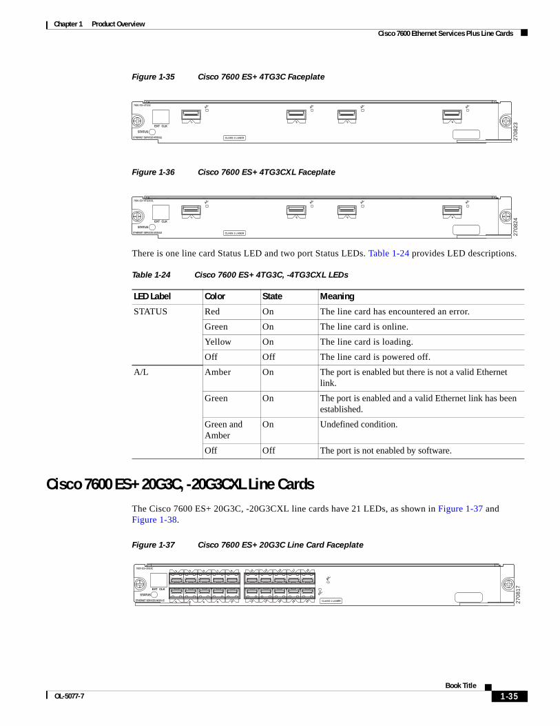
Chapter 1 Product Overview Cisco 7600 Ethernet Services Plus Line Cards
Figure 1-35 Cisco 7600 ES+ 4TG3C Faceplate
Figure 1-36 Cisco 7600 ES+ 4TG3CXL Faceplate
There is one line card Status LED and two port Status LEDs. Table 1-24 provides LED descriptions.
Cisco 7600 ES+ 20G3C, -20G3CXL Line CardsThe Cisco 7600 ES+ 20G3C, -20G3CXL line cards have 21 LEDs, as shown in Figure 1-37 and Figure 1-38.
Figure 1-37 Cisco 7600 ES+ 20G3C Line Card Faceplate
7600-ES+ 4TG3C
ETHERNET SERVICES MODULE
STATUS
EXT CLK
CLASS 1 LASER 2708
23
A/L
1
A/L
2
A/L
3
A/L
4
7600-ES+ 4TG3CXL
ETHERNET SERVICES MODULE
STATUS
EXT CLK
CLASS 1 LASER 2708
24
A/L
1
A/L
2
A/L
3
A/L
4
Table 1-24 Cisco 7600 ES+ 4TG3C, -4TG3CXL LEDs
LED Label Color State Meaning
STATUS Red On The line card has encountered an error.
Green On The line card is online.
Yellow On The line card is loading.
Off Off The line card is powered off.
A/L Amber On The port is enabled but there is not a valid Ethernet link.
Green On The port is enabled and a valid Ethernet link has been established.
Green and Amber
On Undefined condition.
Off Off The port is not enabled by software.
7600-ES+ 20G3C
ETHERNET SERVICES MODULE
STATUS
EXT CLK
12
A/L
A/L
3 5 7 9
4 6 8 10 12 14 16 18
11 13 15 17 1920 CLASS 1 LASER 27
0817
1-35Book Title
OL-5077-7
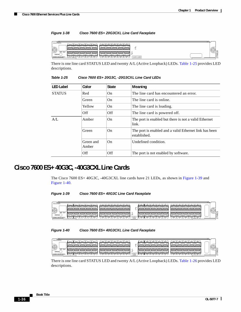
Chapter 1 Product Overview Cisco 7600 Ethernet Services Plus Line Cards
Figure 1-38 Cisco 7600 ES+ 20G3CXL Line Card Faceplate
There is one line card STATUS LED and twenty A/L (Active Loopback) LEDs. Table 1-25 provides LED descriptions.
Cisco 7600 ES+ 40G3C, -40G3CXL Line CardsThe Cisco 7600 ES+ 40G3C, -40G3CXL line cards have 21 LEDs, as shown in Figure 1-39 and Figure 1-40.
Figure 1-39 Cisco 7600 ES+ 40G3C Line Card Faceplate
Figure 1-40 Cisco 7600 ES+ 40G3CXL Line Card Faceplate
There is one line card STATUS LED and twenty A/L (Active Loopback) LEDs. Table 1-26 provides LED descriptions.
7600-ES+ 20G3CXL
ETHERNET SERVICES MODULE
STATUS
EXT CLK
12
A/L
A/L
3 5 7 9
4 6 8 10 12 14 16 18
11 13 15 17 1920 CLASS 1 LASER 27
0818
Table 1-25 Cisco 7600 ES+ 20G3C, -20G3CXL Line Card LEDs
LED Label Color State Meaning
STATUS Red On The line card has encountered an error.
Green On The line card is online.
Yellow On The line card is loading.
Off Off The line card is powered off.
A/L Amber On The port is enabled but there is not a valid Ethernet link.
Green On The port is enabled and a valid Ethernet link has been established.
Green and Amber
On Undefined condition.
Off Off The port is not enabled by software.
2708
21CLASS 1LASER
2122
23 25 27 29
24 26 28 30 32 34 36 38
31 33 35 37 3940
7600-ES+ 40G3C
ETHERNET SERVICES MODULE
STATUS
EXT CLK
12
3 5 7 9
4 6 8 10 12 14 16 18
11 13 15 17 1920
A/L
A/L
2708
22
CLASS 1LASER
2122
23 25 27 29
24 26 28 30 32 34 36 38
31 33 35 37 3940
7600-ES+ 40G3CXL
ETHERNET SERVICES MODULE
STATUS
EXT CLK
12
3 5 7 9
4 6 8 10 12 14 16 18
11 13 15 17 1920
A/L
A/L
1-36Book Title
OL-5077-7
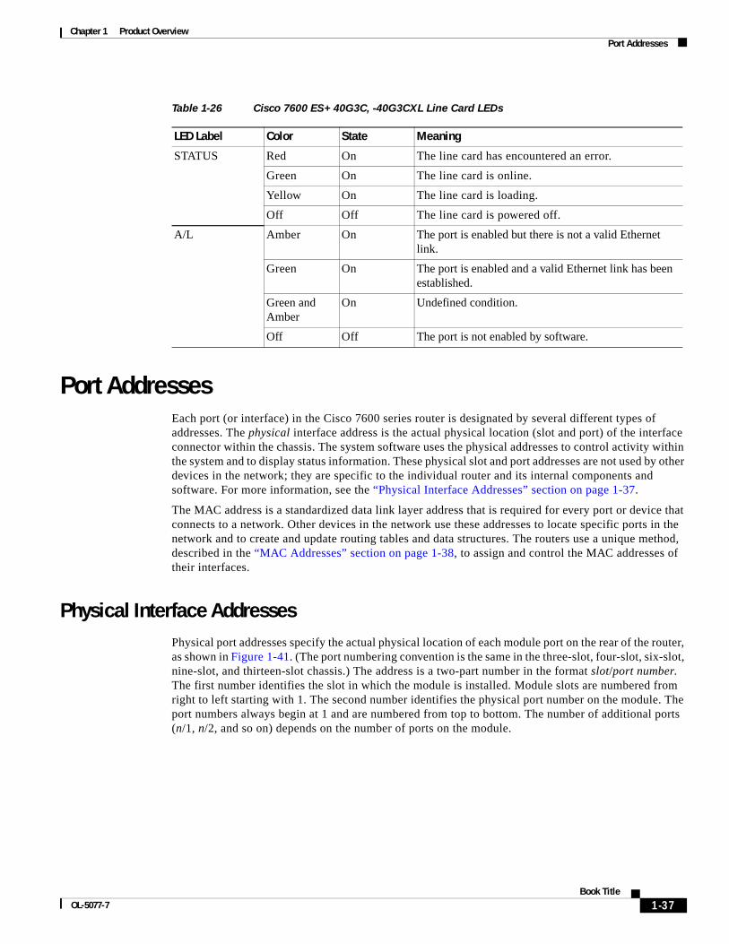
Chapter 1 Product Overview Port Addresses
Port AddressesEach port (or interface) in the Cisco 7600 series router is designated by several different types of addresses. The physical interface address is the actual physical location (slot and port) of the interface connector within the chassis. The system software uses the physical addresses to control activity within the system and to display status information. These physical slot and port addresses are not used by other devices in the network; they are specific to the individual router and its internal components and software. For more information, see the “Physical Interface Addresses” section on page 1-37.
The MAC address is a standardized data link layer address that is required for every port or device that connects to a network. Other devices in the network use these addresses to locate specific ports in the network and to create and update routing tables and data structures. The routers use a unique method, described in the “MAC Addresses” section on page 1-38, to assign and control the MAC addresses of their interfaces.
Physical Interface AddressesPhysical port addresses specify the actual physical location of each module port on the rear of the router, as shown in Figure 1-41. (The port numbering convention is the same in the three-slot, four-slot, six-slot, nine-slot, and thirteen-slot chassis.) The address is a two-part number in the format slot/port number. The first number identifies the slot in which the module is installed. Module slots are numbered from right to left starting with 1. The second number identifies the physical port number on the module. The port numbers always begin at 1 and are numbered from top to bottom. The number of additional ports (n/1, n/2, and so on) depends on the number of ports on the module.
Table 1-26 Cisco 7600 ES+ 40G3C, -40G3CXL Line Card LEDs
LED Label Color State Meaning
STATUS Red On The line card has encountered an error.
Green On The line card is online.
Yellow On The line card is loading.
Off Off The line card is powered off.
A/L Amber On The port is enabled but there is not a valid Ethernet link.
Green On The port is enabled and a valid Ethernet link has been established.
Green and Amber
On Undefined condition.
Off Off The port is not enabled by software.
1-37Book Title
OL-5077-7
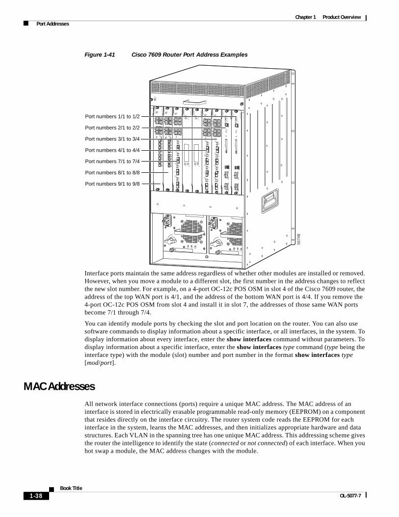
Chapter 1 Product Overview Port Addresses
Figure 1-41 Cisco 7609 Router Port Address Examples
Interface ports maintain the same address regardless of whether other modules are installed or removed. However, when you move a module to a different slot, the first number in the address changes to reflect the new slot number. For example, on a 4-port OC-12c POS OSM in slot 4 of the Cisco 7609 router, the address of the top WAN port is 4/1, and the address of the bottom WAN port is 4/4. If you remove the 4-port OC-12c POS OSM from slot 4 and install it in slot 7, the addresses of those same WAN ports become 7/1 through 7/4.
You can identify module ports by checking the slot and port location on the router. You can also use software commands to display information about a specific interface, or all interfaces, in the system. To display information about every interface, enter the show interfaces command without parameters. To display information about a specific interface, enter the show interfaces type command (type being the interface type) with the module (slot) number and port number in the format show interfaces type [mod/port].
MAC AddressesAll network interface connections (ports) require a unique MAC address. The MAC address of an interface is stored in electrically erasable programmable read-only memory (EEPROM) on a component that resides directly on the interface circuitry. The router system code reads the EEPROM for each interface in the system, learns the MAC addresses, and then initializes appropriate hardware and data structures. Each VLAN in the spanning tree has one unique MAC address. This addressing scheme gives the router the intelligence to identify the state (connected or not connected) of each interface. When you hot swap a module, the MAC address changes with the module.
INPUTOK
FANOK
OUTPUTFAIL
o
INPUTOK
FANOK
OUTPUTFAIL
o
FANSTATUS
5574
8
SU
PE
RV
ISO
R2
WS
-X6K
-SU
P2-2G
E
STATUSSYSTEMCONSO
LEPWR M
GM
T
RESET
CO
NS
OLE
CO
NS
OLE
PO
RT
MO
DE
PC
MC
IAE
JEC
T
PO
RT
1P
OR
T 2
Sw
itch Load 100%
1%
LINKLINK
SU
PE
RV
ISO
R2
WS
-X6K
-SU
P2-2G
E
STATUSSYSTEMCONSO
LEPWR M
GM
T
RESET
CO
NS
OLE
CO
NS
OLE
PO
RT
MO
DE
PC
MC
IAE
JEC
T
PO
RT
1P
OR
T 2
Sw
itch Load 100%
1%
LINKLINK
SW
ITC
H F
AB
RIC
MD
L STATUS
SELECT
NEXT
WS
-C6500-S
FM
ACTIVE
SW
ITC
H F
AB
RIC
MD
L STATUS
SELECT
NEXT
WS
-C6500-S
FM
ACTIVE
OC
12 PO
S M
M
OS
M-40C
12-PO
S-M
M
STATUS
12
34RESET
LINK1
LINK2
LINK3
LINK4
CARRIER
ALARM
ACTIVE
TXRX
TX
PORT 1
RX
CARRIER
ALARM
ACTIVE
TXRX
TX
PORT 2
RX
CARRIER
ALARM
ACTIVE
TXRX
TX
PORT 3
RX
CARRIER
ALARM
ACTIVE
TXRX
TX
RX
OC
12 PO
S M
M
OS
M-40C
12-PO
S-M
M
STATUS
12
34RESET
LINK1
LINK2
LINK3
LINK4
CARRIER
ALARM
ACTIVE
TXRX
TX
PORT 1
RX
CARRIER
ALARM
ACTIVE
TXRX
TX
PORT 2
RX
CARRIER
ALARM
ACTIVE
TXRX
TX
PORT 3
RX
CARRIER
ALARM
ACTIVE
TXRX
TX
RX
OC
12 PO
S M
M
OS
M-40C
12-PO
S-M
M
STATUS
12
34RESET
LINK1
LINK2
LINK3
LINK4
CARRIER
ALARM
ACTIVE
TXRX
TX
PORT 1
RX
CARRIER
ALARM
ACTIVE
TXRX
TX
PORT 2
RX
CARRIER
ALARM
ACTIVE
TXRX
TX
PORT 3
RX
CARRIER
ALARM
ACTIVE
TXRX
TX
RX
8 P
OR
T O
C3 P
OS
MM
OS
M-8
OC
3-P
OS
MM
STATUS
1
1
2
2
3
3
1
2
3
4
4
4
RESET
LINK
CARRIER
ALARM
LINK
LINK
LINK
LINK
5
6
7
8
8 P
OR
T O
C3 P
OS
MM
OS
M-8
OC
3-P
OS
MM
STATUS
1
1
2
2
3
3
1
2
3
4
4
4
RESET
LINK
CARRIER
ALARM
LINK
LINK
LINK
LINK
5
6
7
8
LINKCARRIER
ALARM
LINK
Port numbers 1/1 to 1/2
Port numbers 2/1 to 2/2
Port numbers 3/1 to 3/4
Port numbers 4/1 to 4/4
Port numbers 7/1 to 7/4
Port numbers 8/1 to 8/8
Port numbers 9/1 to 9/8
1-38Book Title
OL-5077-7

Chapter 1 Product Overview Hot Swapping Supervisor Engines and Modules
Hot Swapping Supervisor Engines and ModulesThe Cisco 7600 series routers provide a feature for removing and replacing the redundant supervisor engine, OSMs, Catalyst 6000 family modules, and SIPS without powering down the system. This feature is known as hot swapping.
Note Although the FlexWAN and Enhanced FlexWAN modules support hot swapping, individual port adapters do not. To replace port adapters, you must first remove the FlexWAN module from the chassis and then replace port adapters as required.
When you remove or insert a module while the router is powered on and operating, the system does the following:
1. Determines if there is sufficient power for the module.
2. Scans the backplane for configuration changes.
3. Initializes all newly inserted modules, notes any removed modules, and places them in the administratively shutdown state.
4. Places any previously configured interfaces on the module back to the state they were in when they were removed. Any newly inserted interfaces are put in the administratively shutdown state, as if they were present (but unconfigured) at boot time. If you insert a similar module type into a slot, its ports are configured and brought online up to the port count of the original module.
The system runs diagnostic tests on any new interfaces. If the test passes, the system is operating normally. If the new module is faulty, the system resumes normal operation but leaves the new interface disabled.
If the diagnostic test fails, the system crashes, which usually indicates that the new module has a problem in the bus and should be removed.
When you install two supervisor engines, hot swapping allows you to remove and replace one of the supervisor engines without turning off the system power.
Caution To avoid erroneous failure messages, note the current configuration of all interfaces before you remove or replace another module, and allow at least 15 seconds for the system to reinitialize after a module has been removed or replaced.
Power Management and Environmental MonitoringFor detailed information on power management and environmental monitoring, refer to the Cisco 7600 Series Internet Router Software Configuration Guide.
OSM Technology OverviewThis section provides an overview of SONET/SDH and ATM:
• SONET/SDH Overview, page 1-40
• ATM Overview, page 1-40
1-39Book Title
OL-5077-7
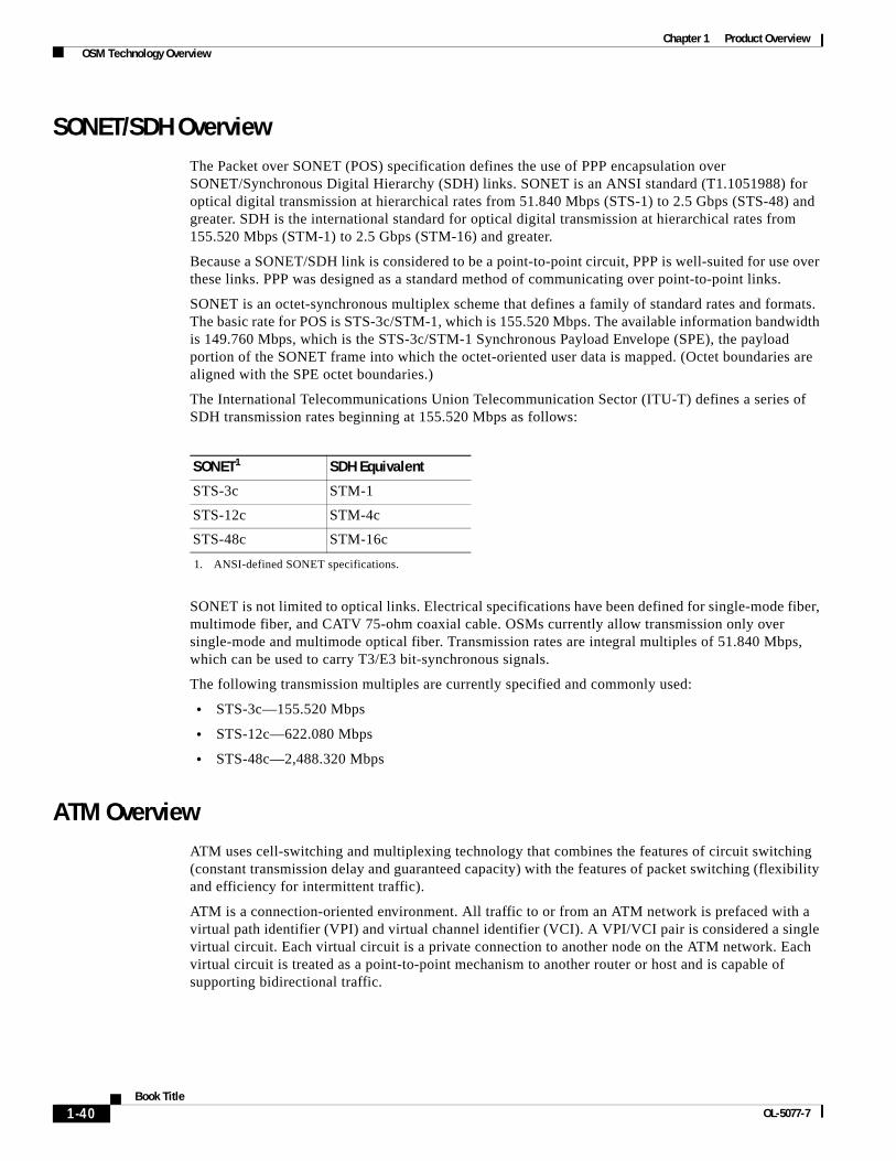
Chapter 1 Product Overview OSM Technology Overview
SONET/SDH OverviewThe Packet over SONET (POS) specification defines the use of PPP encapsulation over SONET/Synchronous Digital Hierarchy (SDH) links. SONET is an ANSI standard (T1.1051988) for optical digital transmission at hierarchical rates from 51.840 Mbps (STS-1) to 2.5 Gbps (STS-48) and greater. SDH is the international standard for optical digital transmission at hierarchical rates from 155.520 Mbps (STM-1) to 2.5 Gbps (STM-16) and greater.
Because a SONET/SDH link is considered to be a point-to-point circuit, PPP is well-suited for use over these links. PPP was designed as a standard method of communicating over point-to-point links.
SONET is an octet-synchronous multiplex scheme that defines a family of standard rates and formats. The basic rate for POS is STS-3c/STM-1, which is 155.520 Mbps. The available information bandwidth is 149.760 Mbps, which is the STS-3c/STM-1 Synchronous Payload Envelope (SPE), the payload portion of the SONET frame into which the octet-oriented user data is mapped. (Octet boundaries are aligned with the SPE octet boundaries.)
The International Telecommunications Union Telecommunication Sector (ITU-T) defines a series of SDH transmission rates beginning at 155.520 Mbps as follows:
SONET is not limited to optical links. Electrical specifications have been defined for single-mode fiber, multimode fiber, and CATV 75-ohm coaxial cable. OSMs currently allow transmission only over single-mode and multimode optical fiber. Transmission rates are integral multiples of 51.840 Mbps, which can be used to carry T3/E3 bit-synchronous signals.
The following transmission multiples are currently specified and commonly used:
• STS-3c—155.520 Mbps
• STS-12c—622.080 Mbps
• STS-48c—2,488.320 Mbps
ATM OverviewATM uses cell-switching and multiplexing technology that combines the features of circuit switching (constant transmission delay and guaranteed capacity) with the features of packet switching (flexibility and efficiency for intermittent traffic).
ATM is a connection-oriented environment. All traffic to or from an ATM network is prefaced with a virtual path identifier (VPI) and virtual channel identifier (VCI). A VPI/VCI pair is considered a single virtual circuit. Each virtual circuit is a private connection to another node on the ATM network. Each virtual circuit is treated as a point-to-point mechanism to another router or host and is capable of supporting bidirectional traffic.
SONET1
1. ANSI-defined SONET specifications.
SDH Equivalent
STS-3c STM-1
STS-12c STM-4c
STS-48c STM-16c
1-40Book Title
OL-5077-7

Chapter 1 Product Overview OSM Technology Overview
Each ATM node is required to establish a separate connection to every other node in the ATM network that it must communicate with. All of these connections are established using a permanent virtual circuit (PVC), which a network operator configures, or a switched virtual circuit (SVC), which is set up and torn down with an ATM signaling mechanism. This signaling is based on the ATM Forum User-Network Interface (UNI) Specification V3.x, 4.0.
1-41Book Title
OL-5077-7

Chapter 1 Product Overview OSM Technology Overview
1-42Book Title
OL-5077-7
OL-5077-7
C H A P T E R 2
Preparing for InstallationThis chapter describes how to prepare your site before you install modules in the Cisco 7600 series routers and contains these sections:
• Safety Guidelines, page 2-1
• Limiting Connection Distances, page 2-10
• Determining Cable Distances, page 2-10
• Port Densities, page 2-18
• Software Requirements, page 2-19
This chapter does not contain the instructions to install the Cisco 7600 series router chassis. Refer to the following documents for installation procedures:
• Cisco 7600 Series Router Installation Guide
• Cisco 7609 Router Installation Guide
Warning Only trained and qualified personnel should be allowed to install, replace, or service this equipment.
Safety GuidelinesThis section provides safety guidelines that you should follow when working with any equipment that connects to electrical power or telephone wiring.
General Precautions Observe the following general precautions while handling the line card hardware:
• Before installing any line card or supervisor engine, inspect both the chassis and the line card connectors and verify that they are not damaged. If damage is present, do not insert the linecard(s) into the chassis. A case should be opened with Cisco TAC to further troubleshoot the problem.
• Take care to insert the linecard through the appropriate guides provided along the sides of the chassis. Failure to do can result in connector damage and a non-functional chassis.
• Verify that the module is properly aligned before inserting it gently into the chassis.
2-1Book Title
Chapter 2 Preparing for Installation Safety Guidelines
Safety WarningsSafety warnings appear throughout this publication in procedures that, if performed incorrectly, may harm you. A warning symbol precedes each warning statement.
Installation Hazard
Warning This equipment must be installed and maintained by service personnel as defined by AS/NZS 3260. Incorrectly connecting this equipment to a general-purpose outlet could be hazardous. The telecommunications lines must be disconnected 1) before unplugging the main power connector or 2) while the housing is open, or both. Statement 1043
Waarschuwing Deze apparatuur dient geïnstalleerd en onderhouden te worden door onderhoudspersoneel zoals gedefinieerd door AS/NZS 3260. Als deze uitrusting onjuist op een stopcontact voor algemeen gebruik wordt aangesloten, kan dit gevaarlijk zijn. De telecommunicatielijnen dienen ontkoppeld te worden 1) voordat de stekker naar de hoofdstroomtoevoer eruit genomen wordt of 2) terwijl de behuizing open is, of in beide gevallen.
Varoitus Huoltohenkilöstön on asennettava ja huollettava tämä laite AS/NZS 3260:n määräysten mukaisesti. Laitteen virheellinen kytkeminen yleispistorasiaan voi aiheuttaa vaaratilanteen. Tietoliikennejohdot on irrotettava 1) ennen kuin päävirtaliitin irrotetaan pistorasiasta ja/tai 2) kun kotelo on auki.
Attention Cet équipement ne doit être installé et entretenu que par du personnel d'entretien conformément à la réglementation AS/NZS 3260. Un branchement incorrect de cet équipement à une prise de courant peut créer une situation dangereuse. Les lignes de télécommunications doivent être déconnectées soit 1) avant de débrancher le connecteur d'alimentation principal, soit 2) lorsque le boîtier est ouvert, soit les deux les deux à la fois.
Warnung Dieses Gerät darf nur von ausgebildetem Personal installiert und gewartet werden (lt. Definition in AS/NZS 3260). Fälschliches Anschließen des Geräts an eine normale Steckdose kann gefährlich sein. Die Telekommunikationsleitungen dürfen nicht angeschlossen sein, wenn 1. der Netzstecker herausgezogen wird oder 2. das Gehäuse geöffnet ist oder beides zutrifft.
Avvertenza Questo apparecchio deve essere installato e mantenuto in efficienza esclusivamente da personale tecnico che soddisfi i requisiti specificati nelle norme AS/NZS 3260. Il collegamento errato di questo apparecchio ad una presa di uso generale può essere pericoloso. Le linee di telecomunicazione vanno scollegate prima di scollegare la spina dell'alimentazione di rete e/o mentre l'involucro è aperto.
2-2Book Title
OL-5077-7

Chapter 2 Preparing for Installation Safety Guidelines
Warning Class 1 Laser Product
Warning Invisible laser radiation may be emitted from disconnected fibers or connectors. Do not stare into beams or view directly with optical instruments.
Advarsel Dette utstyret må monteres og vedlikeholdes av vedlikeholdspersonell i henhold til AS/NZS 3260. Feil tilkobling av dette utstyret til et vanlig strømuttak kan medføre fare. Telekommunikasjonslinjene må være frakoblet 1) før strømledningen trekkes ut av kontakten eller 2) mens huset er åpent, eller begge deler.
Aviso A instalação e a manutenção deste equipamento devem ser realizadas por pessoal da assistência, conforme definido na norma AS/NZS 3260. A ligação incorreta deste equipamento a uma tomada de utilização geral poderá ser perigosa. As linhas de telecomunicações têm de estar desligadas 1) antes de desligar a ligação da corrente principal, e/ou 2) enquanto a caixa de eletricidade estiver aberta.
¡Advertencia! Sólo el personal de servicio puede instalar y mantener este equipo, según lo estipulado en AS/NZS 3260. La conexión incorrecta de este equipo a una toma o receptáculo de tipo general podría resultar peligrosa. Las líneas de telecomunicaciones deben desconectarse 1) antes de desenchufar el conector principal de energía, 2) mientras la caja esté abierta o en ambos casos.
Varning! Denna utrustning måste installeras och underhållas av servicepersonal enligt AS/NZS 3260. Felaktig anslutning av denna utrustning till ett vanligt vägguttag kan medföra fara. Teleledningarna måste kopplas från innan väggkontakten dras ut eller innan höljet tas av eller i båda fallen.
2-3Book Title
OL-5077-7
Chapter 2 Preparing for Installation Safety Guidelines
Warning Laser radiation is present when the system is open.
Warning Do not stare into the beam or view it directly with optical instruments.
Blank Faceplates and Cover Panels
Warning Blank faceplates and cover panels serve three important functions: they prevent exposure to hazardous voltages and currents inside the chassis; they contain electromagnetic interference (EMI) that might disrupt other equipment; and they direct the flow of cooling air through the chassis. Do not operate the system unless all cards, faceplates, front covers, and rear covers are in place. Statement 1029
Waarschuwing Lege vlakplaten en afdekpanelen vervullen drie belangrijke functies: ze voorkomen blootstelling aan gevaarlijke voltages en stroom binnenin het frame, ze bevatten elektromagnetische storing (EMI) hetgeen andere apparaten kan verstoren en ze leiden de stroom van koellucht door het frame. Het systeem niet bedienen tenzij alle kaarten, vlakplaten en afdekkingen aan de voor- en achterkant zich op hun plaats bevinden.
Varoitus Tyhjillä tasolaikoilla ja suojapaneeleilla on kolme tärkeää käyttötarkoitusta: Ne suojaavat asennuspohjan sisäisille vaarallisille jännitteille ja sähkövirralle altistumiselta; ne pitävät sisällään elektromagneettisen häiriön (EMI), joka voi häiritä muita laitteita; ja ne suuntaavat tuuletusilman asennuspohjan läpi. Järjestelmää ei saa käyttää, elleivät kaikki tasolaikat, etukannet ja takakannet ole kunnolla paikoillaan.
Attention Ne jamais faire fonctionner le système sans que l’intégralité des cartes, des plaques métalliques et des panneaux avant et arrière ne soient fixés à leur emplacement. Ceux-ci remplissent trois fonctions essentielles : ils évitent tout risque de contact avec des tensions et des courants dangereux à l’intérieur du châssis, ils évitent toute diffusion d’interférences électromagnétiques qui pourraient perturber le fonctionnement des autres équipements, et ils canalisent le flux d’air de refroidissement dans le châssis.
Warnung Blanke Faceplates und Abdeckungen haben drei wichtigen Funktionen: (1) Sie schützen vor gefährlichen Spannungen und Strom innerhalb des Chassis; (2) sie halten elektromagnetische Interferenzen (EMI) zurück, die andere Geräte stören könnten; (3) sie lenken den kühlenden Luftstrom durch das Chassis. Das System darf nur betrieben werden, wenn alle Karten, Faceplates, Voder- und Rückabdeckungen an Ort und Stelle sind.
2-4Book Title
OL-5077-7
Chapter 2 Preparing for Installation Safety Guidelines
Avvertenza Le piattaforme bianche e i panelli di protezione hanno tre funzioni importanti: Evitano l'esposizione a voltaggi e correnti elettriche pericolose nello chassis, trattengono le interferenze elettromagnetiche (EMI) che potrebbero scombussolare altri apparati e dirigono il flusso di aria per il raffreddamento attraverso lo chassis. Non mettete in funzione il sistema se le schede, le piattaforme, i panelli frontali e posteriori non sono in posizione.
Advarsel Blanke ytterplater og deksler sørger for tre viktige funksjoner: de forhindrer utsettelse for farlig spenning og strøm inni kabinettet; de inneholder elektromagnetisk forstyrrelse (EMI) som kan avbryte annet utstyr, og de dirigerer luftavkjølingsstrømmen gjennom kabinettet. Betjen ikke systemet med mindre alle kort, ytterplater, frontdeksler og bakdeksler sitter på plass.
Aviso As faces furadas e os painéis de protecção desempenham três importantes funções: previnem contra uma exposição perigosa a voltagens e correntes existentes no interior do chassis; previnem contra interferência electromagnética (EMI) que poderá danificar outro equipamento; e canalizam o fluxo do ar de refrigeração através do chassis. Não deverá operar o sistema sem que todas as placas, faces, protecções anteriores e posteriores estejam nos seus lugares.
¡Advertencia! Las placas frontales y los paneles de relleno cumplen tres funciones importantes: evitan la exposición a niveles peligrosos de voltaje y corriente dentro del chasis; reducen la interferencia electromagnética (EMI) que podría perturbar la operación de otros equipos y dirigen el flujo de aire de enfriamiento a través del chasis. No haga funcionar el sistema a menos que todas las tarjetas, placas frontales, cubiertas frontales y cubiertas traseras estén en su lugar.
Varning! Tomma framplattor och skyddspaneler har tre viktiga funktioner: de förhindrar att personer utsätts för farlig spänning och ström som finns inuti chassit; de innehåller elektromagnetisk interferens (EMI) som kan störa annan utrustning; och de styr riktningen på kylluftsflödet genom chassit. Använd inte systemet om inte alla kort, framplattor, fram- och bakskydd är på plats.
2-5Book Title
OL-5077-7

Chapter 2 Preparing for Installation Safety Guidelines
Backplane Voltage
Warning Hazardous voltage or energy is present on the backplane when the system is operating. Use caution when servicing. Statement 1034
Waarschuwing Er is gevaarlijke spanning of energie aanwezig op de achterplaat wanneer het systeem bediend wordt. Wees voorzichtig bij het onderhoud.
Varoitus Kun laite on toiminnassa, taustalevyyn muodostuu vaarallista jännitettä. Ole varovainen huoltaessasi laitetta.
Attention Lorsque le système est en fonctionnement, des tensions électriques circulent sur le fond de panier. Prendre des précautions lors de la maintenance.
Warnung Wenn das System in Betrieb ist, treten auf der Rückwandplatine gefährliche Spannungen oder Energien auf. Vorsicht bei der Wartung.
Avvertenza Quando il sistema è in funzione, il pannello posteriore è sotto tensione pericolosa. Prestare attenzione quando si lavora sul sistema.
Advarsel Farlig spenning er til stede på bakpanelet når systemet kjøres. Utvis forsiktighet under service.
Aviso Há presença de voltagem perigosa ou de energia na placa traseira quando o sistema está em operação. Tenha cuidado ao fazer a manutenção.
¡Advertencia! Cuando el sistema está en funcionamiento, el voltaje del plano trasero es peligroso. Tenga cuidado cuando lo revise.
Varning! Farlig spänning föreligger på bakplattan när systemet körs. Var försiktig vid service.
2-6Book Title
OL-5077-7

Chapter 2 Preparing for Installation Safety Guidelines
SELV Circuit
Warning To avoid electric shock, do not connect safety extra-low voltage (SELV) circuits to telephone-network voltage (TNV) circuits. LAN ports contain SELV circuits, and WAN ports contain TNV circuits. Some LAN and WAN ports both use RJ-45 connectors. Use caution when connecting cables. Statement 1021
Waarschuwing Om elektrische schokken te vermijden, mogen veiligheidscircuits met extra lage spanning (genaamd SELV = Safety Extra-Low Voltage) niet met telefoonnetwerkspanning (TNV) circuits verbonden worden. LAN (Lokaal netwerk) poorten bevatten SELV circuits en WAN (Regionaal netwerk) poorten bevatten TNV circuits. Sommige LAN en WAN poorten gebruiken allebei RJ-45 connectors. Ga voorzichtig te werk wanneer u kabels verbindt.
Varoitus Jotta vältyt sähköiskulta, älä kytke pienjännitteisiä SELV-suojapiirejä puhelinverkkojännitettä (TNV) käyttäviin virtapiireihin. LAN-portit sisältävät SELV-piirejä ja WAN-portit puhelinverkkojännitettä käyttäviä piirejä. Osa sekä LAN- että WAN-porteista käyttää RJ-45-liittimiä. Ole varovainen kytkiessäsi kaapeleita.
Attention Pour éviter une électrocution, ne raccordez pas les circuits de sécurité basse tension (Safety Extra-Low Voltage ou SELV) à des circuits de tension de réseau téléphonique (Telephone Network Voltage ou TNV). Les ports du réseau local (LAN) contiennent des circuits SELV et les ports du réseau longue distance (WAN) sont munis de circuits TNV. Certains ports LAN et WAN utilisent des connecteurs RJ-45. Raccordez les câbles en prenant toutes les précautions nécessaires.
Warnung Zur Vermeidung von Elektroschock die Sicherheits-Kleinspannungs-Stromkreise (SELV-Kreise) nicht an Fernsprechnetzspannungs-Stromkreise (TNV-Kreise) anschließen. LAN-Ports enthalten SELV-Kreise, und WAN-Ports enthalten TNV-Kreise. Einige LAN- und WAN-Ports verwenden auch RJ-45-Steckverbinder. Vorsicht beim Anschließen von Kabeln.
2-7Book Title
OL-5077-7

Chapter 2 Preparing for Installation Safety Guidelines
Avvertenza Per evitare scosse elettriche, non collegare circuiti di sicurezza a tensione molto bassa (SELV) ai circuiti a tensione di rete telefonica (TNV). Le porte LAN contengono circuiti SELV e le porte WAN contengono circuiti TNV. Alcune porte LAN e WAN fanno uso di connettori RJ-45. Fare attenzione quando si collegano cavi.
Advarsel Unngå å koble lavspenningskretser (SELV) til kretser for telenettspenning (TNV), slik at du unngår elektrisk støt. LAN-utganger inneholder SELV-kretser og WAN-utganger inneholder TNV-kretser. Det finnes både LAN-utganger og WAN-utganger som bruker RJ-45-kontakter. Vær forsiktig når du kobler kabler.
Aviso Para evitar choques eléctricos, não conecte os circuitos de segurança de baixa tensão (SELV) aos circuitos de tensão de rede telefónica (TNV). As portas LAN contêm circuitos SELV e as portas WAN contêm circuitos TNV. Algumas portas LAN e WAN usam conectores RJ-45. Tenha o devido cuidado ao conectar os cabos.
¡Advertencia! Para evitar la sacudida eléctrica, no conectar circuitos de seguridad de voltaje muy bajo (safety extra-low voltage = SELV) con circuitos de voltaje de red telefónica (telephone network voltage = TNV). Los puertos de redes de área local (local area network = LAN) contienen circuitos SELV, y los puertos de redes de área extendida (wide area network = WAN) contienen circuitos TNV. En algunos casos, tanto los puertos LAN como los WAN usan conectores RJ-45. Proceda con precaución al conectar los cables.
Varning! För att undvika elektriska stötar, koppla inte säkerhetskretsar med extra låg spänning (SELV-kretsar) till kretsar med telefonnätspänning (TNV-kretsar). LAN-portar innehåller SELV-kretsar och WAN-portar innehåller TNV-kretsar. Vissa LAN- och WAN-portar är försedda med RJ-45-kontakter. Iaktta försiktighet vid anslutning av kablar.
2-8Book Title
OL-5077-7
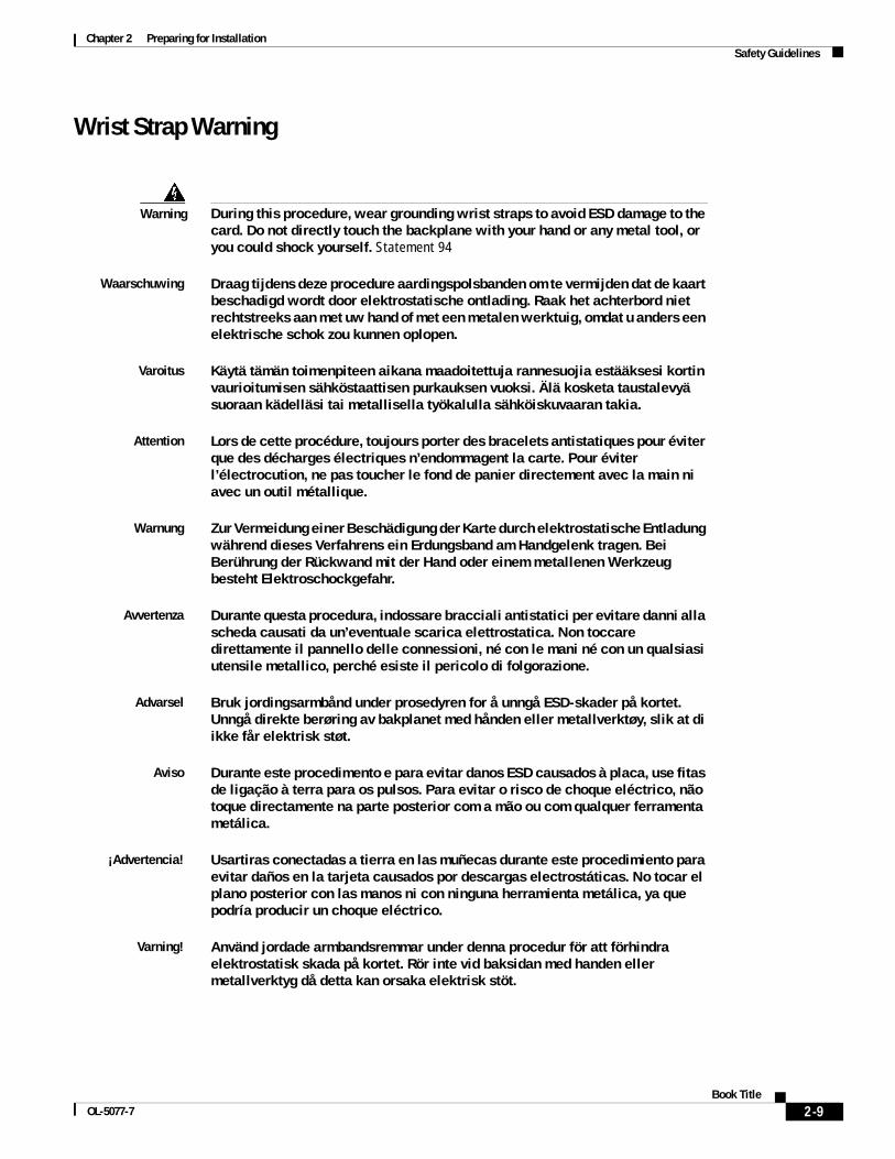
Chapter 2 Preparing for Installation Safety Guidelines
Wrist Strap Warning
Warning During this procedure, wear grounding wrist straps to avoid ESD damage to the card. Do not directly touch the backplane with your hand or any metal tool, or you could shock yourself. Statement 94
Waarschuwing Draag tijdens deze procedure aardingspolsbanden om te vermijden dat de kaart beschadigd wordt door elektrostatische ontlading. Raak het achterbord niet rechtstreeks aan met uw hand of met een metalen werktuig, omdat u anders een elektrische schok zou kunnen oplopen.
Varoitus Käytä tämän toimenpiteen aikana maadoitettuja rannesuojia estääksesi kortin vaurioitumisen sähköstaattisen purkauksen vuoksi. Älä kosketa taustalevyä suoraan kädelläsi tai metallisella työkalulla sähköiskuvaaran takia.
Attention Lors de cette procédure, toujours porter des bracelets antistatiques pour éviter que des décharges électriques n’endommagent la carte. Pour éviter l’électrocution, ne pas toucher le fond de panier directement avec la main ni avec un outil métallique.
Warnung Zur Vermeidung einer Beschädigung der Karte durch elektrostatische Entladung während dieses Verfahrens ein Erdungsband am Handgelenk tragen. Bei Berührung der Rückwand mit der Hand oder einem metallenen Werkzeug besteht Elektroschockgefahr.
Avvertenza Durante questa procedura, indossare bracciali antistatici per evitare danni alla scheda causati da un’eventuale scarica elettrostatica. Non toccare direttamente il pannello delle connessioni, né con le mani né con un qualsiasi utensile metallico, perché esiste il pericolo di folgorazione.
Advarsel Bruk jordingsarmbånd under prosedyren for å unngå ESD-skader på kortet. Unngå direkte berøring av bakplanet med hånden eller metallverktøy, slik at di ikke får elektrisk støt.
Aviso Durante este procedimento e para evitar danos ESD causados à placa, use fitas de ligação à terra para os pulsos. Para evitar o risco de choque eléctrico, não toque directamente na parte posterior com a mão ou com qualquer ferramenta metálica.
¡Advertencia! Usartiras conectadas a tierra en las muñecas durante este procedimiento para evitar daños en la tarjeta causados por descargas electrostáticas. No tocar el plano posterior con las manos ni con ninguna herramienta metálica, ya que podría producir un choque eléctrico.
Varning! Använd jordade armbandsremmar under denna procedur för att förhindra elektrostatisk skada på kortet. Rör inte vid baksidan med handen eller metallverktyg då detta kan orsaka elektrisk stöt.
2-9Book Title
OL-5077-7
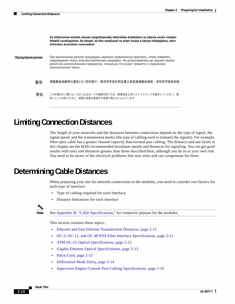
Chapter 2 Preparing for Installation Limiting Connection Distances
Limiting Connection DistancesThe length of your networks and the distances between connections depend on the type of signal, the signal speed, and the transmission media (the type of cabling used to transmit the signals). For example, fiber-optic cable has a greater channel capacity than twisted-pair cabling. The distance and rate limits in this chapter are the IEEE-recommended maximum speeds and distances for signaling. You can get good results with rates and distances greater than those described here, although you do so at your own risk. You need to be aware of the electrical problems that may arise and can compensate for them.
Determining Cable DistancesWhen preparing your site for network connections to the modules, you need to consider two factors for each type of interface:
• Type of cabling required for each interface
• Distance limitations for each interface
Note See Appendix B, “Cable Specifications,” for connector pinouts for the modules.
This section contains these topics:
• Ethernet and Fast Ethernet Transmission Distances, page 2-11
• OC-3, OC-12, and OC-48 POS Fiber Interface Specifications, page 2-11
• ATM OC-12 Optical Specifications, page 2-12
• Gigabit Ethernet Optical Specifications, page 2-13
• Patch Cord, page 2-13
• Differential Mode Delay, page 2-14
• Supervisor Engine Console Port Cabling Specifications, page 2-16
2-10Book Title
OL-5077-7
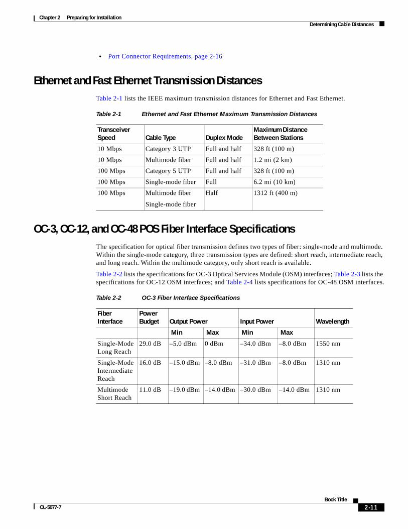
Chapter 2 Preparing for Installation Determining Cable Distances
• Port Connector Requirements, page 2-16
Ethernet and Fast Ethernet Transmission DistancesTable 2-1 lists the IEEE maximum transmission distances for Ethernet and Fast Ethernet.
OC-3, OC-12, and OC-48 POS Fiber Interface SpecificationsThe specification for optical fiber transmission defines two types of fiber: single-mode and multimode. Within the single-mode category, three transmission types are defined: short reach, intermediate reach, and long reach. Within the multimode category, only short reach is available.
Table 2-2 lists the specifications for OC-3 Optical Services Module (OSM) interfaces; Table 2-3 lists the specifications for OC-12 OSM interfaces; and Table 2-4 lists specifications for OC-48 OSM interfaces.
Table 2-1 Ethernet and Fast Ethernet Maximum Transmission Distances
Transceiver Speed Cable Type Duplex Mode
Maximum Distance Between Stations
10 Mbps Category 3 UTP Full and half 328 ft (100 m)
10 Mbps Multimode fiber Full and half 1.2 mi (2 km)
100 Mbps Category 5 UTP Full and half 328 ft (100 m)
100 Mbps Single-mode fiber Full 6.2 mi (10 km)
100 Mbps Multimode fiber
Single-mode fiber
Half 1312 ft (400 m)
Table 2-2 OC-3 Fiber Interface Specifications
Fiber Interface
Power Budget Output Power Input Power Wavelength
Min Max Min Max
Single-Mode Long Reach
29.0 dB –5.0 dBm 0 dBm –34.0 dBm –8.0 dBm 1550 nm
Single-Mode Intermediate Reach
16.0 dB –15.0 dBm –8.0 dBm –31.0 dBm –8.0 dBm 1310 nm
Multimode Short Reach
11.0 dB –19.0 dBm –14.0 dBm –30.0 dBm –14.0 dBm 1310 nm
2-11Book Title
OL-5077-7
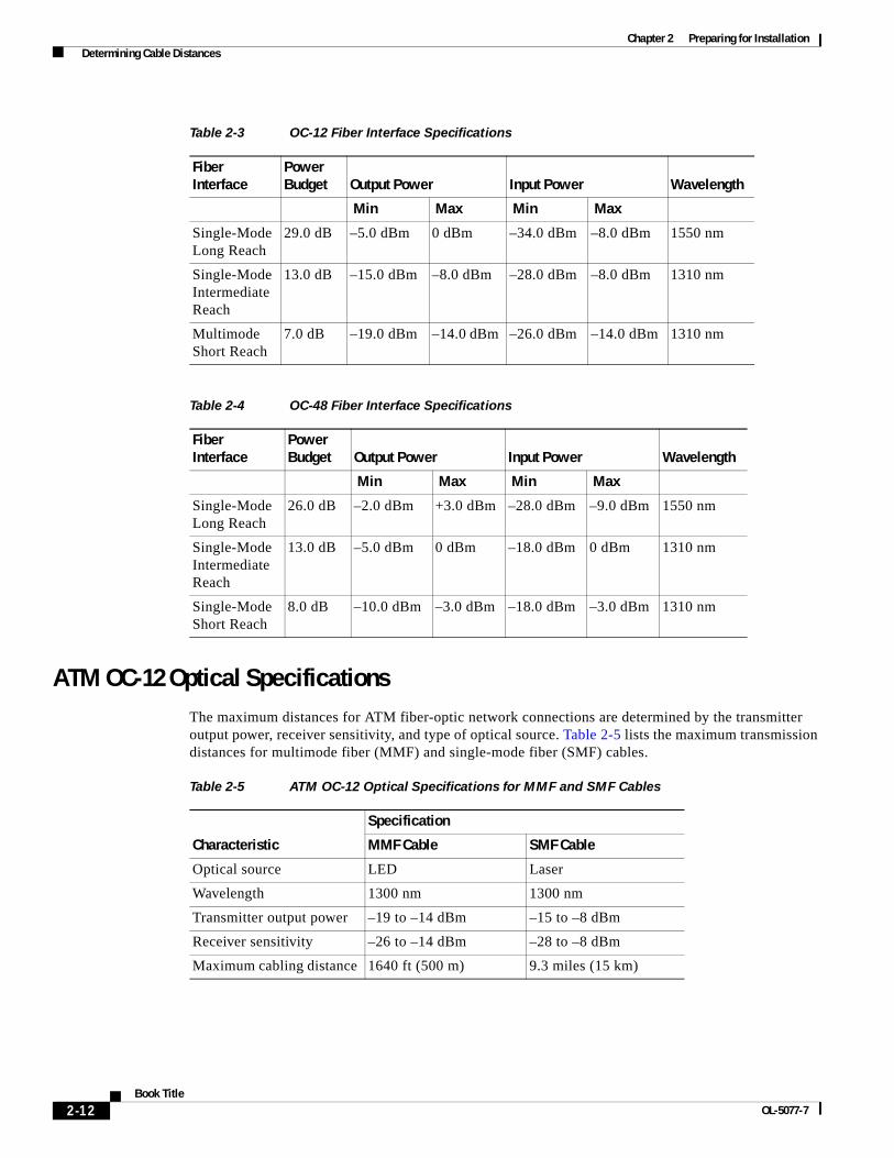
Chapter 2 Preparing for Installation Determining Cable Distances
ATM OC-12 Optical SpecificationsThe maximum distances for ATM fiber-optic network connections are determined by the transmitter output power, receiver sensitivity, and type of optical source. Table 2-5 lists the maximum transmission distances for multimode fiber (MMF) and single-mode fiber (SMF) cables.
Table 2-3 OC-12 Fiber Interface Specifications
Fiber Interface
Power Budget Output Power Input Power Wavelength
Min Max Min Max
Single-Mode Long Reach
29.0 dB –5.0 dBm 0 dBm –34.0 dBm –8.0 dBm 1550 nm
Single-Mode Intermediate Reach
13.0 dB –15.0 dBm –8.0 dBm –28.0 dBm –8.0 dBm 1310 nm
Multimode Short Reach
7.0 dB –19.0 dBm –14.0 dBm –26.0 dBm –14.0 dBm 1310 nm
Table 2-4 OC-48 Fiber Interface Specifications
Fiber Interface
Power Budget Output Power Input Power Wavelength
Min Max Min Max
Single-Mode Long Reach
26.0 dB –2.0 dBm +3.0 dBm –28.0 dBm –9.0 dBm 1550 nm
Single-Mode Intermediate Reach
13.0 dB –5.0 dBm 0 dBm –18.0 dBm 0 dBm 1310 nm
Single-Mode Short Reach
8.0 dB –10.0 dBm –3.0 dBm –18.0 dBm –3.0 dBm 1310 nm
Table 2-5 ATM OC-12 Optical Specifications for MMF and SMF Cables
Characteristic
Specification
MMF Cable SMF Cable
Optical source LED Laser
Wavelength 1300 nm 1300 nm
Transmitter output power –19 to –14 dBm –15 to –8 dBm
Receiver sensitivity –26 to –14 dBm –28 to –8 dBm
Maximum cabling distance 1640 ft (500 m) 9.3 miles (15 km)
2-12Book Title
OL-5077-7
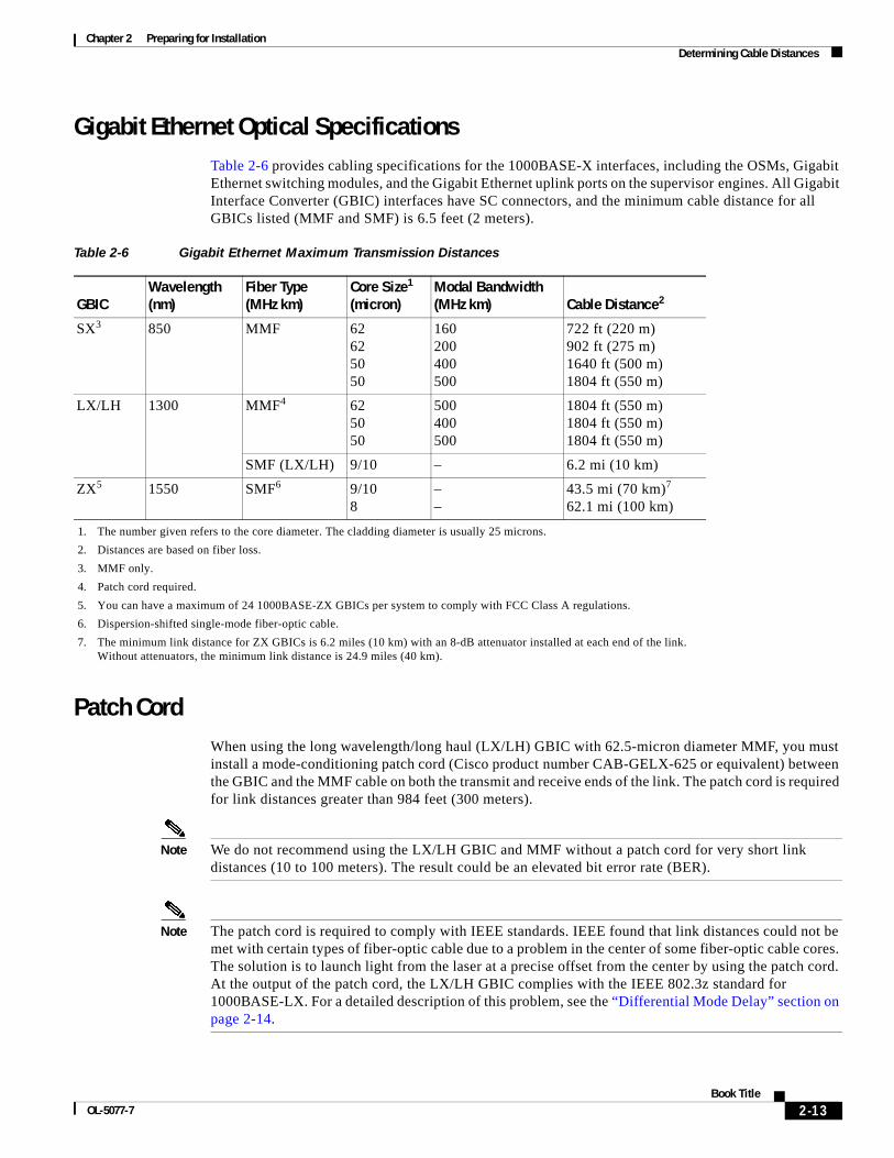
Chapter 2 Preparing for Installation Determining Cable Distances
Gigabit Ethernet Optical SpecificationsTable 2-6 provides cabling specifications for the 1000BASE-X interfaces, including the OSMs, Gigabit Ethernet switching modules, and the Gigabit Ethernet uplink ports on the supervisor engines. All Gigabit Interface Converter (GBIC) interfaces have SC connectors, and the minimum cable distance for all GBICs listed (MMF and SMF) is 6.5 feet (2 meters).
Patch CordWhen using the long wavelength/long haul (LX/LH) GBIC with 62.5-micron diameter MMF, you must install a mode-conditioning patch cord (Cisco product number CAB-GELX-625 or equivalent) between the GBIC and the MMF cable on both the transmit and receive ends of the link. The patch cord is required for link distances greater than 984 feet (300 meters).
Note We do not recommend using the LX/LH GBIC and MMF without a patch cord for very short link distances (10 to 100 meters). The result could be an elevated bit error rate (BER).
Note The patch cord is required to comply with IEEE standards. IEEE found that link distances could not be met with certain types of fiber-optic cable due to a problem in the center of some fiber-optic cable cores. The solution is to launch light from the laser at a precise offset from the center by using the patch cord. At the output of the patch cord, the LX/LH GBIC complies with the IEEE 802.3z standard for 1000BASE-LX. For a detailed description of this problem, see the “Differential Mode Delay” section on page 2-14.
Table 2-6 Gigabit Ethernet Maximum Transmission Distances
GBICWavelength (nm)
Fiber Type (MHz km)
Core Size1 (micron)
1. The number given refers to the core diameter. The cladding diameter is usually 25 microns.
Modal Bandwidth (MHz km) Cable Distance2
2. Distances are based on fiber loss.
SX3
3. MMF only.
850 MMF 62 62 50 50
160 200 400 500
722 ft (220 m) 902 ft (275 m) 1640 ft (500 m) 1804 ft (550 m)
LX/LH 1300 MMF4
4. Patch cord required.
62 50 50
500 400 500
1804 ft (550 m) 1804 ft (550 m) 1804 ft (550 m)
SMF (LX/LH) 9/10 – 6.2 mi (10 km)
ZX5
5. You can have a maximum of 24 1000BASE-ZX GBICs per system to comply with FCC Class A regulations.
1550 SMF6
6. Dispersion-shifted single-mode fiber-optic cable.
9/10 8
– –
43.5 mi (70 km)7 62.1 mi (100 km)
7. The minimum link distance for ZX GBICs is 6.2 miles (10 km) with an 8-dB attenuator installed at each end of the link. Without attenuators, the minimum link distance is 24.9 miles (40 km).
2-13Book Title
OL-5077-7
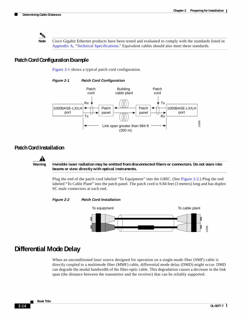
Chapter 2 Preparing for Installation Determining Cable Distances
Note Cisco Gigabit Ethernet products have been tested and evaluated to comply with the standards listed in Appendix A, “Technical Specifications.” Equivalent cables should also meet these standards.
Patch Cord Configuration Example
Figure 2-1 shows a typical patch cord configuration.
Figure 2-1 Patch Cord Configuration
Patch Cord Installation
Warning Invisible laser radiation may be emitted from disconnected fibers or connectors. Do not stare into beams or view directly with optical instruments.
Plug the end of the patch cord labeled “To Equipment” into the GBIC. (See Figure 2-2.) Plug the end labeled “To Cable Plant” into the patch panel. The patch cord is 9.84 feet (3 meters) long and has duplex SC male connectors at each end.
Figure 2-2 Patch Cord Installation
Differential Mode DelayWhen an unconditioned laser source designed for operation on a single-mode fiber (SMF) cable is directly coupled to a multimode fiber (MMF) cable, differential mode delay (DMD) might occur. DMD can degrade the modal bandwidth of the fiber-optic cable. This degradation causes a decrease in the link span (the distance between the transmitter and the receiver) that can be reliably supported.
1000BASE-LX/LHport
Patchpanel
Link span greater than 984 ft(300 m)
1000BASE-LX/LHport
Rx
Tx
Patchpanel
Patchcord
Building cable plant
Tx
Rx
Patchcord
1308
8
To equipment To cable plant13
089
2-14Book Title
OL-5077-7
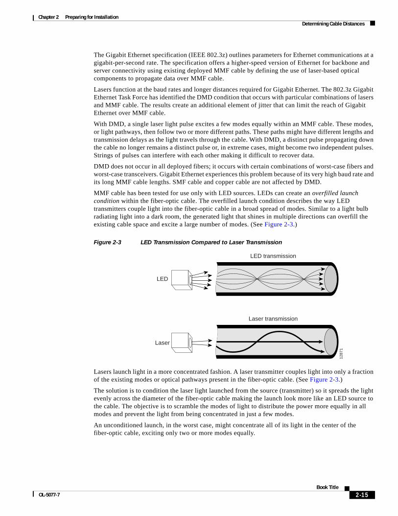
Chapter 2 Preparing for Installation Determining Cable Distances
The Gigabit Ethernet specification (IEEE 802.3z) outlines parameters for Ethernet communications at a gigabit-per-second rate. The specification offers a higher-speed version of Ethernet for backbone and server connectivity using existing deployed MMF cable by defining the use of laser-based optical components to propagate data over MMF cable.
Lasers function at the baud rates and longer distances required for Gigabit Ethernet. The 802.3z Gigabit Ethernet Task Force has identified the DMD condition that occurs with particular combinations of lasers and MMF cable. The results create an additional element of jitter that can limit the reach of Gigabit Ethernet over MMF cable.
With DMD, a single laser light pulse excites a few modes equally within an MMF cable. These modes, or light pathways, then follow two or more different paths. These paths might have different lengths and transmission delays as the light travels through the cable. With DMD, a distinct pulse propagating down the cable no longer remains a distinct pulse or, in extreme cases, might become two independent pulses. Strings of pulses can interfere with each other making it difficult to recover data.
DMD does not occur in all deployed fibers; it occurs with certain combinations of worst-case fibers and worst-case transceivers. Gigabit Ethernet experiences this problem because of its very high baud rate and its long MMF cable lengths. SMF cable and copper cable are not affected by DMD.
MMF cable has been tested for use only with LED sources. LEDs can create an overfilled launch condition within the fiber-optic cable. The overfilled launch condition describes the way LED transmitters couple light into the fiber-optic cable in a broad spread of modes. Similar to a light bulb radiating light into a dark room, the generated light that shines in multiple directions can overfill the existing cable space and excite a large number of modes. (See Figure 2-3.)
Figure 2-3 LED Transmission Compared to Laser Transmission
Lasers launch light in a more concentrated fashion. A laser transmitter couples light into only a fraction of the existing modes or optical pathways present in the fiber-optic cable. (See Figure 2-3.)
The solution is to condition the laser light launched from the source (transmitter) so it spreads the light evenly across the diameter of the fiber-optic cable making the launch look more like an LED source to the cable. The objective is to scramble the modes of light to distribute the power more equally in all modes and prevent the light from being concentrated in just a few modes.
An unconditioned launch, in the worst case, might concentrate all of its light in the center of the fiber-optic cable, exciting only two or more modes equally.
LED transmission
Laser transmission
1287
1
LED
Laser
2-15Book Title
OL-5077-7
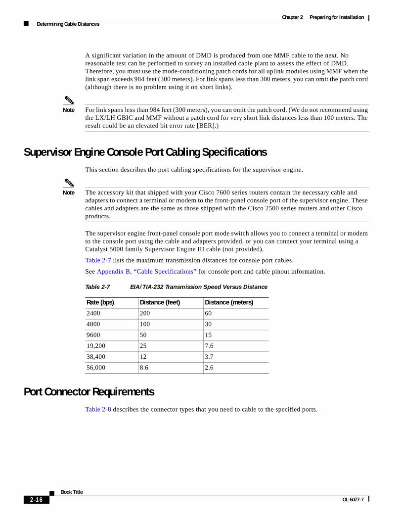
Chapter 2 Preparing for Installation Determining Cable Distances
A significant variation in the amount of DMD is produced from one MMF cable to the next. No reasonable test can be performed to survey an installed cable plant to assess the effect of DMD. Therefore, you must use the mode-conditioning patch cords for all uplink modules using MMF when the link span exceeds 984 feet (300 meters). For link spans less than 300 meters, you can omit the patch cord (although there is no problem using it on short links).
Note For link spans less than 984 feet (300 meters), you can omit the patch cord. (We do not recommend using the LX/LH GBIC and MMF without a patch cord for very short link distances less than 100 meters. The result could be an elevated bit error rate [BER].)
Supervisor Engine Console Port Cabling SpecificationsThis section describes the port cabling specifications for the supervisor engine.
Note The accessory kit that shipped with your Cisco 7600 series routers contain the necessary cable and adapters to connect a terminal or modem to the front-panel console port of the supervisor engine. These cables and adapters are the same as those shipped with the Cisco 2500 series routers and other Cisco products.
The supervisor engine front-panel console port mode switch allows you to connect a terminal or modem to the console port using the cable and adapters provided, or you can connect your terminal using a Catalyst 5000 family Supervisor Engine III cable (not provided).
Table 2-7 lists the maximum transmission distances for console port cables.
See Appendix B, “Cable Specifications” for console port and cable pinout information.
Port Connector RequirementsTable 2-8 describes the connector types that you need to cable to the specified ports.
Table 2-7 EIA/TIA-232 Transmission Speed Versus Distance
Rate (bps) Distance (feet) Distance (meters)
2400 200 60
4800 100 30
9600 50 15
19,200 25 7.6
38,400 12 3.7
56,000 8.6 2.6
2-16Book Title
OL-5077-7

Chapter 2 Preparing for Installation Determining Cable Distances
Figure 2-4 SC Fiber-Optic Connector
Figure 2-5 LC Fiber-Optic Connector
Figure 2-6 MT-RJ Interface Cable Connector
Table 2-8 Port Connector Requirements
Modules Connectors
1-port OC-48 POS OSM 2-port and 4-port OC-12 POS OSM 2-port OC-12 ATM Gigabit Ethernet WAN Services Module Gigabit Ethernet switching modules with GBICs
SC connectors. (See Figure 2-4.)1, 2
1. When you plug the SC connector into the GBIC, make sure that both the Tx and Rx fiber-optic cables are fully inserted into the SC connector.
2. If you are using the LX/LH GBIC with MMF, you need to install a patch cord between the GBIC and the MMF cable. See the “Patch Cord” section on page 2-13 for details.
1-port and 2-port channelized OC-48 OSM 4-port and 8-port channelized OC-12 OSM
LC fiber-optic connectors. (See Figure 2-5.)
8-port and 16-port OC-3 POS OSM MT-RJ fiber-optic connectors. (See Figure 2-6.)
48-port 10/100TX RJ-45 modules RJ-45 male connectors. (See Figure 2-7.)
12-port channelized T3 module Mini-SMB connectors (See Figure 2-8.)
H22
14
5847
6
1436
7
2-17Book Title
OL-5077-7
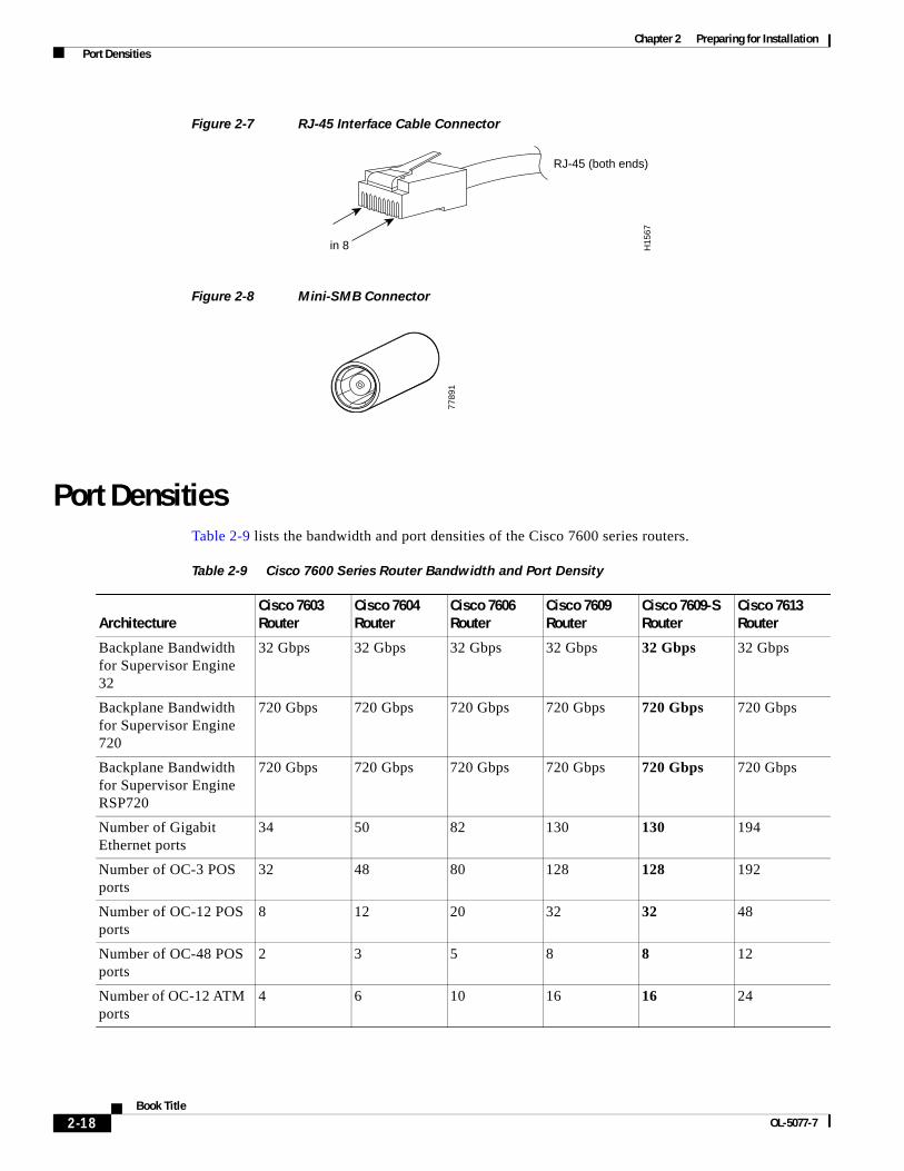
Chapter 2 Preparing for Installation Port Densities
Figure 2-7 RJ-45 Interface Cable Connector
Figure 2-8 Mini-SMB Connector
Port DensitiesTable 2-9 lists the bandwidth and port densities of the Cisco 7600 series routers.
H15
67
1
Pin 8
RJ-45 (both ends)
7789
1
Table 2-9 Cisco 7600 Series Router Bandwidth and Port Density
ArchitectureCisco 7603 Router
Cisco 7604 Router
Cisco 7606 Router
Cisco 7609 Router
Cisco 7609-S Router
Cisco 7613 Router
Backplane Bandwidth for Supervisor Engine 32
32 Gbps 32 Gbps 32 Gbps 32 Gbps 32 Gbps 32 Gbps
Backplane Bandwidth for Supervisor Engine 720
720 Gbps 720 Gbps 720 Gbps 720 Gbps 720 Gbps 720 Gbps
Backplane Bandwidth for Supervisor Engine RSP720
720 Gbps 720 Gbps 720 Gbps 720 Gbps 720 Gbps 720 Gbps
Number of Gigabit Ethernet ports
34 50 82 130 130 194
Number of OC-3 POS ports
32 48 80 128 128 192
Number of OC-12 POS ports
8 12 20 32 32 48
Number of OC-48 POS ports
2 3 5 8 8 12
Number of OC-12 ATM ports
4 6 10 16 16 24
2-18Book Title
OL-5077-7
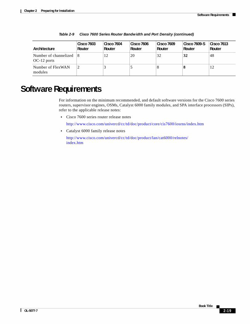
Chapter 2 Preparing for Installation Software Requirements
Software RequirementsFor information on the minimum recommended, and default software versions for the Cisco 7600 series routers, supervisor engines, OSMs, Catalyst 6000 family modules, and SPA interface processors (SIPs), refer to the applicable release notes:
• Cisco 7600 series router release notes
http://www.cisco.com/univercd/cc/td/doc/product/core/cis7600/iosrns/index.htm
• Catalyst 6000 family release notes
http://www.cisco.com/univercd/cc/td/doc/product/lan/cat6000/relnotes/ index.htm
Number of channelized OC-12 ports
8 12 20 32 32 48
Number of FlexWAN modules
2 3 5 8 8 12
Table 2-9 Cisco 7600 Series Router Bandwidth and Port Density (continued)
ArchitectureCisco 7603 Router
Cisco 7604 Router
Cisco 7606 Router
Cisco 7609 Router
Cisco 7609-S Router
Cisco 7613 Router
2-19Book Title
OL-5077-7

Chapter 2 Preparing for Installation Software Requirements
2-20Book Title
OL-5077-7
OL-5077-7
C H A P T E R 3
Installing ModulesThis chapter describes how to install and verify the operation of the supervisor engines, Optical Services Modules (OSMs), recommended Catalyst 6000 family modules, and SPA interface processors (SIPs) in the Cisco 7600 series router, and it contains these sections:
• Required Tools, page 3-1
• Installing a Supervisor Engine or a Module, page 3-2
• Removing the Supervisor Engine or a Module, page 3-13
• Connecting the Supervisor Engine, page 3-15
• Installing and Removing GBICs, page 3-17
• Using Flash PC Cards, page 3-20
• Verifying the Installation, page 3-22
Required ToolsThis section describes the requirements and the tools you need to install the supervisor engine or the module.
Note Before installing modules, you must install the Cisco 7600 series router chassis and at least one supervisor engine. For information on installing the chassis, refer to the Cisco 7600 Series Router Installation Guide or Cisco 7609 Router Installation Guide.
These tools are required to install modules in the Cisco 7600 series router:
• Flat-blade screwdriver
• Wrist strap or other grounding device
• Antistatic mat or antistatic foam
3-1Book Title

Chapter 3 Installing Modules Installing a Supervisor Engine or a Module
Preventing Electrostatic Discharge DamageElectrostatic discharge (ESD) damage, which can occur when electronic cards or components are improperly handled, results in complete or intermittent failures. Port adapters and processor modules consist of printed circuit boards that are fixed in metal carriers. Electromagnetic interference (EMI) shielding and connectors are integral components of the carrier. Although the metal carrier helps to protect the board from ESD, use a preventive antistatic strap during handling.
Following are guidelines for preventing ESD damage:
• Always use an ESD wrist or ankle strap and ensure that it makes good skin contact.
• Connect the equipment end of the strap to an unfinished chassis surface.
• When installing a component, use any available ejector levers or captive installation screws to properly seat the bus connectors in the backplane or midplane. These devices prevent accidental removal, provide proper grounding for the system, and help to ensure that bus connectors are properly seated.
• When removing a component, use any available ejector levers or captive installation screws to release the bus connectors from the backplane or midplane.
• Handle carriers by available handles or edges only; avoid touching the printed circuit boards or connectors.
• Place a removed component board-side-up on an antistatic surface or in a static shielding container. If you plan to return the component to the factory, immediately place it in a static shielding container.
• Avoid contact between the printed circuit boards and clothing. The wrist strap only protects components from ESD voltages on the body; ESD voltages on clothing can still cause damage.
• Never attempt to remove the printed circuit board from the metal carrier.
Installing a Supervisor Engine or a ModuleThis section describes how to install a supervisor engine, OSM, or recommended Catalyst 6000 family module in the Cisco 7600 series router.
Supervisor engines must be installed in specific slots in the chassis depending on which model of supervisor engine you are installing. Table 3-1 lists the specific slot assignments for the different supervisor engine models.
3-2Book Title
OL-5077-7
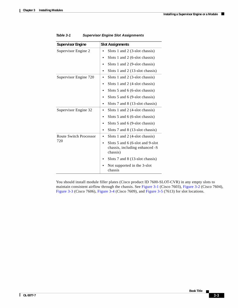
Chapter 3 Installing Modules Installing a Supervisor Engine or a Module
You should install module filler plates (Cisco product ID 7600-SLOT-CVR) in any empty slots to maintain consistent airflow through the chassis. See Figure 3-1 (Cisco 7603), Figure 3-2 (Cisco 7604), Figure 3-3 (Cisco 7606), Figure 3-4 (Cisco 7609), and Figure 3-5 (7613) for slot locations.
Table 3-1 Supervisor Engine Slot Assignments
Supervisor Engine Slot Assignments
Supervisor Engine 2 • Slots 1 and 2 (3-slot chassis)
• Slots 1 and 2 (6-slot chassis)
• Slots 1 and 2 (9-slot chassis)
• Slots 1 and 2 (13-slot chassis)
Supervisor Engine 720 • Slots 1 and 2 (3-slot chassis)
• Slots 1 and 2 (4-slot chassis)
• Slots 5 and 6 (6-slot chassis)
• Slots 5 and 6 (9-slot chassis)
• Slots 7 and 8 (13-slot chassis)
Supervisor Engine 32 • Slots 1 and 2 (4-slot chassis)
• Slots 5 and 6 (6-slot chassis)
• Slots 5 and 6 (9-slot chassis)
• Slots 7 and 8 (13-slot chassis)
Route Switch Processor 720
• Slots 1 and 2 (4-slot chassis)
• Slots 5 and 6 (6-slot and 9-slot chassis, including enhanced -S chassis)
• Slots 7 and 8 (13-slot chassis)
• Not supported in the 3-slot chassis
3-3Book Title
OL-5077-7
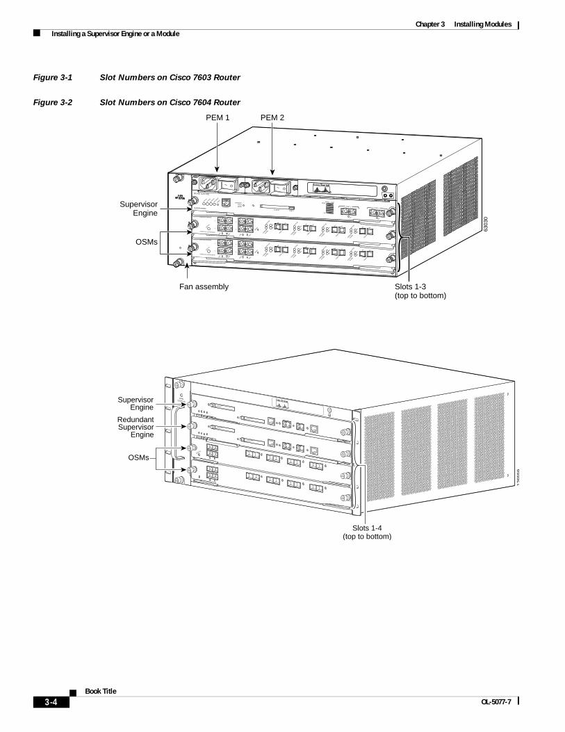
Chapter 3 Installing Modules Installing a Supervisor Engine or a Module
Figure 3-1 Slot Numbers on Cisco 7603 Router
Figure 3-2 Slot Numbers on Cisco 7604 Router
SUPERVISOR2
WS-X6K-SUP2-2GE
STATUS
SYSTEM
CONSOLE
PWR M
GMT
RESET
CONSOLE
CONSOLEPORTMODE
PCMCIA EJECT
PORT 1PORT 2
Switch Load 100%
1%
LINK
LINK
OSM-4OC12 POS-SI
4 PORT OC-12 POS SM IR
STATUS
1
1
2
2
3
3
4
4
RESET
LINK
LINK
LINK
LINK
CARRIER
ALARM
CARRIER
ALARM
CARRIER
ALARM
CARRIER
ALARM
ACTIVE
TXRX
TX
PORT 1
RX
ACTIVE
TXRX
TX
PORT 2
RX
ACTIVE
TXRX
TX
PORT 3
RX
ACTIVE
TXRX
TX
PORT4
RX
OSM-4OC12 POS-SI
4 PORT OC-12 POS SM IR
STATUS
1
1
2
2
3
3
4
4
RESET
LINK
LINK
LINK
LINK
CARRIER
ALARM
CARRIER
ALARM
CARRIER
ALARM
CARRIER
ALARM
ACTIVE
TXRX
TX
PORT 1
RX
ACTIVE
TXRX
TX
PORT 2
RX
ACTIVE
TXRX
TX
PORT 3
RX
ACTIVE
TXRX
TX
PORT4
RX
6303
0
Slots 1-3(top to bottom)
Fan assembly
PEM 1 PEM 2
SupervisorEngine
OSMs
1265
59
STATUS
FANSTATUS
STATUS
Slots 1-4(top to bottom)
SupervisorEngine
OSMs
RedundantSupervisor
Engine
3-4Book Title
OL-5077-7

Chapter 3 Installing Modules Installing a Supervisor Engine or a Module
Figure 3-3 Supervisor Engine 720s and Route Switch Processor 720s are installed in slots 1 and 2. The illustration shows one supervisor engine.Slot Numbers on Cisco 7606 Router
Note Supervisor Engine 2 is installed in slot 1 and slot 2. Supervisor Engine 720s and Route Switch Processor 720s are installed in slot 5 and slot 6.
OSM-4OC12 POS-SI
4 PORT OC-12 POS SM IR
STATUS
1
1
2
2
3
3
4
4
RESET
LINK
LINK
LINK
LINK
CARRIER
ALARM
CARRIER
ALARM
CARRIER
ALARM
CARRIER
ALARM
ACTIVE
TXRX
TX
PORT 1
RX
ACTIVE
TXRX
TX
PORT 2
RX
ACTIVE
TXRX
TX
PORT 3
RX
ACTIVE
TXRX
TX
PORT4
RX
OSM-4OC12 POS-SI
4 PORT OC-12 POS SM IR
STATUS
1
1
2
2
3
3
4
4
RESET
LINK
LINK
LINK
LINK
CARRIER
ALARM
CARRIER
ALARM
CARRIER
ALARM
CARRIER
ALARM
ACTIVE
TXRX
TX
PORT 1
RX
ACTIVE
TXRX
TX
PORT 2
RX
ACTIVE
TXRX
TX
PORT 3
RX
ACTIVE
TXRX
TX
PORT4
RX
OSM-4OC12 POS-SI
4 PORT OC-12 POS SM IR
STATUS
1
1
2
2
3
3
4
4
RESET
LINK
LINK
LINK
LINK
CARRIER
ALARM
CARRIER
ALARM
CARRIER
ALARM
CARRIER
ALARM
ACTIVE
TXRX
TX
PORT 1
RX
ACTIVE
TXRX
TX
PORT 2
RX
ACTIVE
TXRX
TX
PORT 3
RX
ACTIVE
TXRX
TX
PORT4
RX
OSM-4OC12 POS-SI
4 PORT OC-12 POS SM IR
STATUS
1
1
2
2
3
3
4
4
RESET
LINK
LINK
LINK
LINK
CARRIER
ALARM
CARRIER
ALARM
CARRIER
ALARM
CARRIER
ALARM
ACTIVE
TXRX
TX
PORT 1
RX
ACTIVE
TXRX
TX
PORT 2
RX
ACTIVE
TXRX
TX
PORT 3
RX
ACTIVE
TXRX
TX
PORT4
RX
6389
2
Slots 1-6(top to bottom)Fan assembly
SupervisorEngine
OSMs
4
5
6
PEM 1 PEM 2
RedundantSupervisor
Engine
3-5Book Title
OL-5077-7
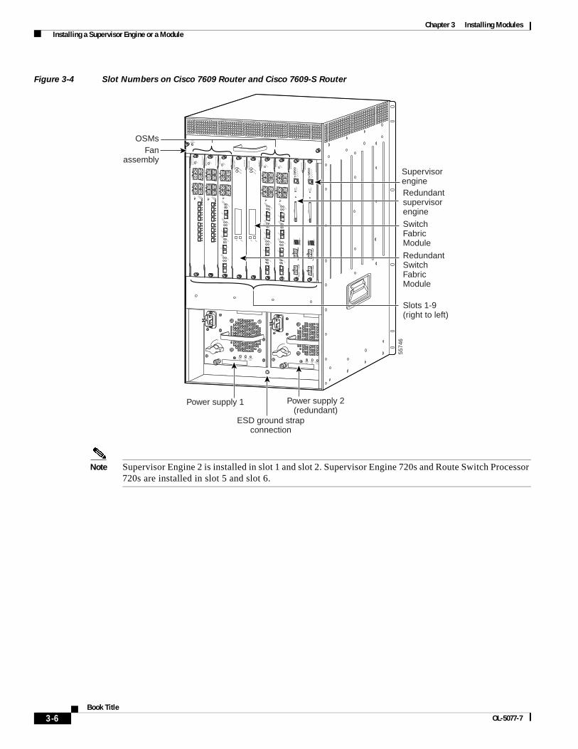
Chapter 3 Installing Modules Installing a Supervisor Engine or a Module
Figure 3-4 Slot Numbers on Cisco 7609 Router and Cisco 7609-S Router
Note Supervisor Engine 2 is installed in slot 1 and slot 2. Supervisor Engine 720s and Route Switch Processor 720s are installed in slot 5 and slot 6.
INPUTOK
FANOK
OUTPUTFAIL
o
INPUTOK
FANOK
OUTPUTFAIL
o
FANSTATUS
5574
6
SupervisorengineRedundantsupervisorengine
RedundantSwitchFabricModule
Slots 1-9(right to left)
Power supply 1 Power supply 2(redundant)
ESD ground strapconnection
OSMsFan
assembly SU
PE
RV
ISO
R2
WS
-X6K
-SU
P2-2G
E
STATUSSYSTEMCONSO
LEPWR M
GM
T
RESET
CO
NS
OLE
CO
NS
OLE
PO
RT
MO
DE
PC
MC
IAE
JEC
T
PO
RT
1P
OR
T 2
Sw
itch Load 100%
1%
LINKLINK
SU
PE
RV
ISO
R2
WS
-X6K
-SU
P2-2G
E
STATUSSYSTEMCONSO
LEPWR M
GM
T
RESET
CO
NS
OLE
CO
NS
OLE
PO
RT
MO
DE
PC
MC
IAE
JEC
T
PO
RT
1P
OR
T 2
Sw
itch Load 100%
1%
LINKLINK
SW
ITC
H F
AB
RIC
MD
L STATUS
SELECT
NEXT
WS
-C6500-S
FM
ACTIVE
SW
ITC
H F
AB
RIC
MD
L STATUS
SELECT
NEXT
WS
-C6500-S
FM
ACTIVE
OC
12 PO
S M
M
OS
M-40C
12-PO
S-M
M
STATUS
12
34RESET
LINK1
LINK2
LINK3
LINK4
CARRIER
ALARM
ACTIVE
TXRX
TX
PORT 1
RX
CARRIER
ALARM
ACTIVE
TXRX
TX
PORT 2
RX
CARRIER
ALARM
ACTIVE
TXRX
TX
PORT 3
RX
CARRIER
ALARM
ACTIVE
TXRX
TX
RX
OC
12 PO
S M
M
OS
M-40C
12-PO
S-M
M
STATUS
12
34RESET
LINK1
LINK2
LINK3
LINK4
CARRIER
ALARM
ACTIVE
TXRX
TX
PORT 1
RX
CARRIER
ALARM
ACTIVE
TXRX
TX
PORT 2
RX
CARRIER
ALARM
ACTIVE
TXRX
TX
PORT 3
RX
CARRIER
ALARM
ACTIVE
TXRX
TX
RX
OC
12 PO
S M
M
OS
M-40C
12-PO
S-M
M
STATUS
12
34RESET
LINK1
LINK2
LINK3
LINK4
CARRIER
ALARM
ACTIVE
TXRX
TX
PORT 1
RX
CARRIER
ALARM
ACTIVE
TXRX
TX
PORT 2
RX
CARRIER
ALARM
ACTIVE
TXRX
TX
PORT 3
RX
CARRIER
ALARM
ACTIVE
TXRX
TX
RX
8 P
OR
T O
C3 P
OS
MM
OS
M-8
OC
3-P
OS
MM
STATUS
1
1
2
2
3
3
1
2
3
4
4
4
RESET
LINK
CARRIER
ALARM
LINK
LINK
LINK
LINK
5
6
7
8
8 P
OR
T O
C3 P
OS
MM
OS
M-8
OC
3-P
OS
MM
STATUS
1
1
2
2
3
3
1
2
3
4
4
4
RESET
LINK
CARRIER
ALARM
LINK
LINK
LINK
LINK
5
6
7
8
LINK
SwitchFabricModule
CARRIER
ALARM
LINK
3-6Book Title
OL-5077-7
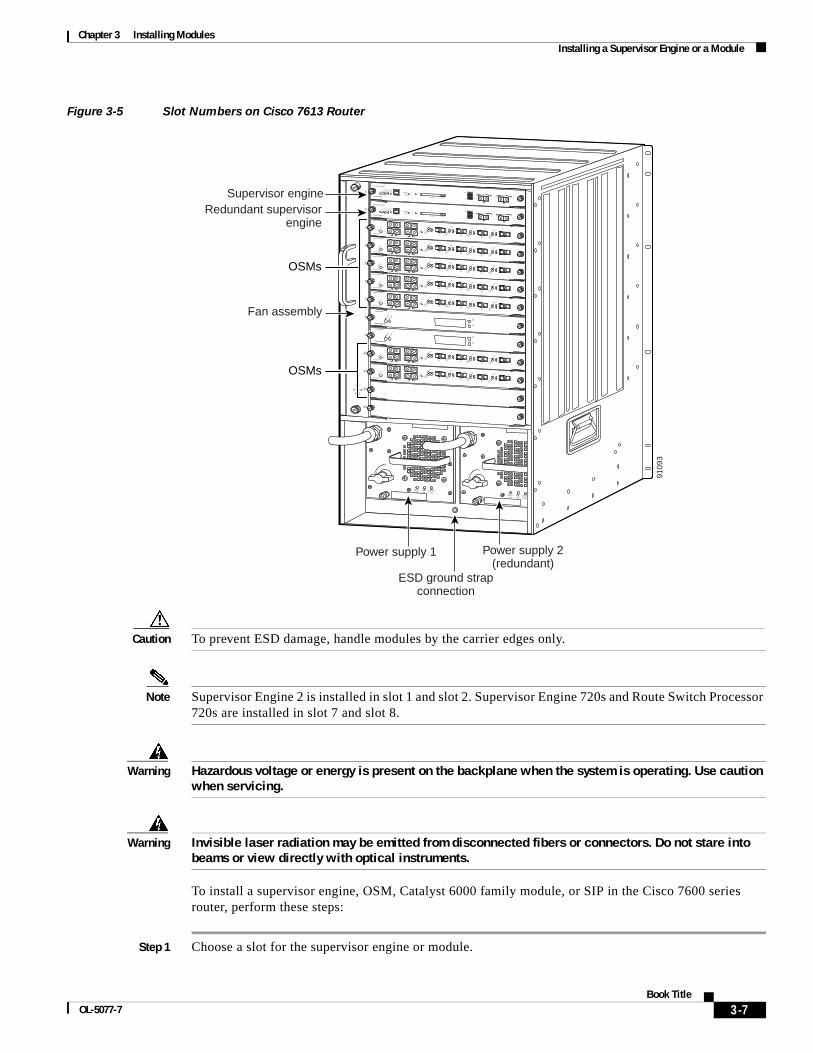
Chapter 3 Installing Modules Installing a Supervisor Engine or a Module
Figure 3-5 Slot Numbers on Cisco 7613 Router
Caution To prevent ESD damage, handle modules by the carrier edges only.
Note Supervisor Engine 2 is installed in slot 1 and slot 2. Supervisor Engine 720s and Route Switch Processor 720s are installed in slot 7 and slot 8.
Warning Hazardous voltage or energy is present on the backplane when the system is operating. Use caution when servicing.
Warning Invisible laser radiation may be emitted from disconnected fibers or connectors. Do not stare into beams or view directly with optical instruments.
To install a supervisor engine, OSM, Catalyst 6000 family module, or SIP in the Cisco 7600 series router, perform these steps:
Step 1 Choose a slot for the supervisor engine or module.
INPUTOK
FANOK
OUTPUTFAIL
o
INPUTOK
FANOK
OUTPUTFAIL
o 9109
3
Power supply 1 Power supply 2(redundant)
ESD ground strapconnection
FANSTATUS
SUPERVISOR2
WS-X6K-SUP2-2GE
STATUS
SYSTEM
CONSOLE
PWR M
GMT
RESET
CONSOLE
CONSOLEPORTMODE
PCMCIA EJECT
PORT 1PORT 2
Switch Load 100%
1%
LINK
LINK
SUPERVISOR2
WS-X6K-SUP2-2GE
STATUS
SYSTEM
CONSOLE
PWR M
GMT
RESET
CONSOLE
CONSOLEPORTMODE
PCMCIA EJECT
PORT 1PORT 2
Switch Load 100%
1%
LINK
LINK
1
2
3
4
5
6
7
8
9
10
11
12
13
Fan assembly
OSMs
OSMs
Supervisor engineRedundant supervisor
engineOC12 POS MM
OSM-40C12-POS-MM
STATUS
1
2
3
4 RESET
LINK
1LIN
K2
LINK
3LIN
K4
CARRIER
ALARM
ACTIVE
TXRX
TX
PORT 1
RX
CARRIER
ALARM
ACTIVE
TXRX
TX
PORT 2
RX
CARRIER
ALARM
ACTIVE
TXRX
TX
PORT 3
RX
CARRIER
ALARM
ACTIVE
TXRX
TX
RX
OC12 POS MM
OSM-40C12-POS-MM
STATUS
1
2
3
4 RESET
LINK
1LIN
K2
LINK
3LIN
K4
CARRIER
ALARM
ACTIVE
TXRX
TX
PORT 1
RX
CARRIER
ALARM
ACTIVE
TXRX
TX
PORT 2
RX
CARRIER
ALARM
ACTIVE
TXRX
TX
PORT 3
RX
CARRIER
ALARM
ACTIVE
TXRX
TX
RX
OC12 POS MM
OSM-40C12-POS-MM
STATUS
1
2
3
4 RESET
LINK
1LIN
K2
LINK
3LIN
K4
CARRIER
ALARM
ACTIVE
TXRX
TX
PORT 1
RX
CARRIER
ALARM
ACTIVE
TXRX
TX
PORT 2
RX
CARRIER
ALARM
ACTIVE
TXRX
TX
PORT 3
RX
CARRIER
ALARM
ACTIVE
TXRX
TX
RX
OC12 POS MM
OSM-40C12-POS-MM
STATUS
1
2
3
4 RESET
LINK
1LIN
K2
LINK
3LIN
K4
CARRIER
ALARM
ACTIVE
TXRX
TX
PORT 1
RX
CARRIER
ALARM
ACTIVE
TXRX
TX
PORT 2
RX
CARRIER
ALARM
ACTIVE
TXRX
TX
PORT 3
RX
CARRIER
ALARM
ACTIVE
TXRX
TX
RX
OC12 POS MM
OSM-40C12-POS-MM
STATUS
1
2
3
4 RESET
LINK
1LIN
K2
LINK
3LIN
K4
CARRIER
ALARM
ACTIVE
TXRX
TX
PORT 1
RX
CARRIER
ALARM
ACTIVE
TXRX
TX
PORT 2
RX
CARRIER
ALARM
ACTIVE
TXRX
TX
PORT 3
RX
CARRIER
ALARM
ACTIVE
TXRX
TX
RX
OC12 POS MM
OSM-40C12-POS-MM
STATUS
1
2
3
4 RESET
LINK
1LIN
K2
LINK
3LIN
K4
CARRIER
ALARM
ACTIVE
TXRX
TX
PORT 1
RX
CARRIER
ALARM
ACTIVE
TXRX
TX
PORT 2
RX
CARRIER
ALARM
ACTIVE
TXRX
TX
PORT 3
RX
CARRIER
ALARM
ACTIVE
TXRX
TX
RX
OC12 POS MM
OSM-40C12-POS-MM
STATUS
1
2
3
4 RESET
LINK
1LIN
K2
LINK
3LIN
K4
CARRIER
ALARM
ACTIVE
TXRX
TX
PORT 1
RX
CARRIER
ALARM
ACTIVE
TXRX
TX
PORT 2
RX
CARRIER
ALARM
ACTIVE
TXRX
TX
PORT 3
RX
CARRIER
ALARM
ACTIVE
TXRX
TX
RX
SWITCH FABRIC MDL
STATU
S
SELECT
NEXT
WS-C6500-SFM
ACTIVE
SWITCH FABRIC MDL
STATU
S
SELECT
NEXT
WS-C6500-SFM
ACTIVE
3-7Book Title
OL-5077-7

Chapter 3 Installing Modules Installing a Supervisor Engine or a Module
Step 2 Make sure that there is enough clearance to accommodate any interface equipment that you will connect directly to the supervisor engine or module ports. If possible, place modules between empty slots that contain only module filler plates.
Step 3 Verify that the captive installation screws are tightened on all modules installed in the chassis to ensure that the EMI gaskets on all modules are fully compressed in order to maximize the opening space for the new or replacement module.
Note If the captive installation screws are loose, the EMI gaskets on the installed modules will push adjacent modules toward the open slot, reducing the opening size and making it difficult to install the replacement module.
Step 4 Remove the module filler plate by removing the two Phillips pan-head screws from the filler plate. To remove a module, follow the procedure in the “Removing the Supervisor Engine or a Module” section on page 3-13.
Step 5 Fully open both ejector levers on the new module. (See Figure 3-6.)
Figure 3-6 Ejector Levers and Captive Installation Screws
Step 6 Depending on the position of the slots in the chassis (horizontal or vertical), perform one of these two sets of substeps:
Horizontal slot
a. Position the supervisor engine or module in the slot. (See Figure 3-7.) Make sure that you align the sides of the module carrier with the slot guides on each side of the slot.
b. Carefully slide the module into the slot until the EMI gasket along the top edge of the module makes contact with the module in the slot above it and both ejector levers have closed to approximately 45 degrees with respect to the module faceplate. (See Figure 3-8.)
c. Using the thumb and forefinger of each hand, grasp the two ejector levers and press down to create a small (0.040 inch [1 mm]) gap between the module’s EMI gasket and the module above it. (See Figure 3-8.)
Caution Do not press down too forcefully on the ejector levers. They will bend and be damaged.
4516
8
4 PORT OC-12 POS MM
OSM-4OC12-POS-MM
STATUS
1
1
2
2
3
3
4
4
RESET
LINK
LINK
LINK
LINK
CARRIER
ALARM
ACTIVE
TXRX TX
PORT 1
RX
CARRIER
ALARM
ACTIVE
TXRX TX
PORT 2
RX
CARRIER
ALARM
ACTIVE
TXRX TX
PORT 3
RX
CARRIER
ALARM
ACTIVE
TXRX TX
PORT 4
RX
Ejector lever
Captiveinstallation screws
3-8Book Title
OL-5077-7

Chapter 3 Installing Modules Installing a Supervisor Engine or a Module
d. While pressing down, simultaneously close the left and right ejector levers to fully seat the supervisor engine or module in the backplane connector. The ejector levers are fully closed when they are flush with the module faceplate. (See Figure 3-9.)
Note Failure to fully seat the module in the backplane connector can result in error messages.
e. Tighten the two captive installation screws on the supervisor engine or module.
Note Make sure the ejector levers are fully closed before tightening the captive installation screws.
3-9Book Title
OL-5077-7
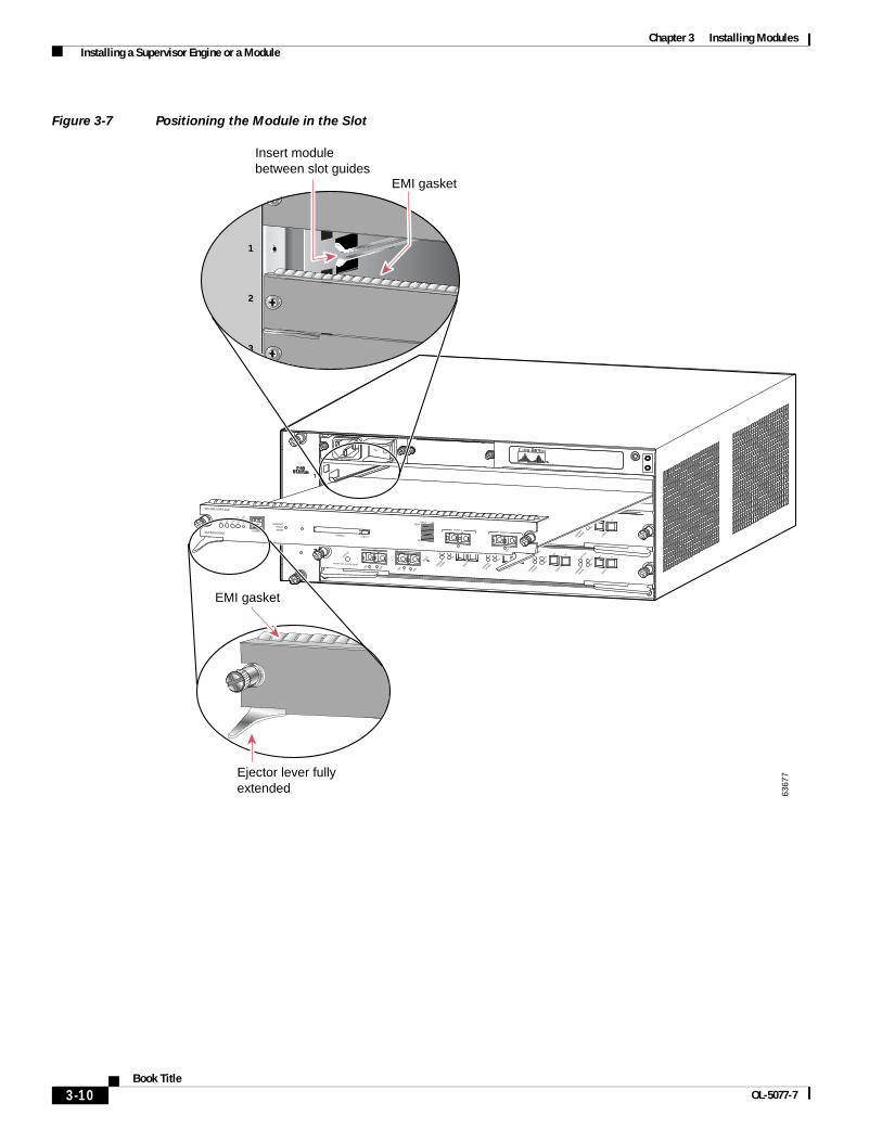
Chapter 3 Installing Modules Installing a Supervisor Engine or a Module
Figure 3-7 Positioning the Module in the Slot
OSM-4OC12 POS-SI
4 PORT OC-12 POS SM IR
STATUS
1
1
2
2
3
3
4
4
RESET
LINK
LINK
LINK
LINK
CARRIER
ALARM
CARRIER
ALARM
CARRIER
ALARM
CARRIER
ALARM
ACTIVE
TXRX
TX
PORT 1
RX
ACTIVE
TXRX
TX
PORT 2
RX
ACTIVE
TXRX
TX
PORT 3
RX
ACTIVE
TXRX
TX
PORT4
RX
OSM-4OC12 POS-SI
4 PORT OC-12 POS SM IR
STATUS
1
1
2
2
3
3
4
4
RESET
LINK
LINK
LINK
LINK
CARRIER
ALARM
CARRIER
ALARM
CARRIER
ALARM
CARRIER
ALARM
ACTIVE
TXRX
TX
PORT 1
RX
ACTIVE
TXRX
TX
PORT 2
RX
ACTIVE
TXRX
TX
PORT 3
RX
ACTIVE
TXRX
TX
PORT4
RX
SUPERVISOR2
WS-X6K-SUP2-2GE
STATUS
SYSTEM
CONSOLE
PWR M
GMT
RESET
CONSOLE
CONSOLEPORTMODE
PCMCIA EJECT
PORT 1PORT 2
Switch Load 100%
1%
LINK
3
2
1
3 6
EMI gasket
Ejector lever fully extended 63
677
EMI gasket
Insert module between slot guides
3-10Book Title
OL-5077-7

Chapter 3 Installing Modules Installing a Supervisor Engine or a Module
Figure 3-8 Clearing the EMI Gasket
Figure 3-9 Ejector Lever Closure
Vertical slots
a. Position the supervisor engine or module in the slot. Make sure that you align the sides of the module carrier with the slot guides on the top and bottom of the slot. (See Figure 3-10.)
6367
8
OSM-4OC12 POS-SI
4 PORT OC-12 POS SM IR
STATUS
1
1
2
2
3
3
4
4
RESET
LINK
LINK
LINK
LINK
CARRIER
ALARM
CARRIER
ALARM
CARRIER
ALARM
CARRIER
ALARM
ACTIVE
TXRX
TX
PORT 1
RX
ACTIVE
TXRX
TX
PORT 2
RX
ACTIVE
TXRX
TX
PORT 3
RX
ACTIVE
TXRX
TX
PORT4
RX
OSM-4OC12 POS-SI
4 PORT OC-12 POS SM IR
STATUS
1
1
2
2
3
3
4
4
RESET
LINK
LINK
LINK
LINK
CARRIER
ALARM
CARRIER
ALARM
CARRIER
ALARM
CARRIER
ALARM
ACTIVE
TXRX
TX
PORT 1
RX
ACTIVE
TXRX
TX
PORT 2
RX
ACTIVE
TXRX
TX
PORT 3
RX
ACTIVE
TXRX
TX
PORT4
RX
SUPERVISOR2
WS-X6K-SUP2-2GE
STATUS
SYSTEM
CONSOLE
PWR M
GMT
RESET
CONSOLE
CONSOLEPORTMODE
PCMCIA EJECT
PORT 1PORT 2
Switch Load 100%
1%
LINK
LINK
1mm 5
4
6
Gap between the moduleEMI gasket and the module above it.
Press downPress down
SUPERVISOR2
WS-X6K-SUP2-2GE
STATUS
SYSTEM
CONSOLE
PWR M
GMT
RESET
CONSOLE
CONSOLEPORTMODE
PCMCIA EJECT
PORT 1PORT 2
Switch Load 100%
1%
LINK
LINK
OSM-4OC12 POS-SI
4 PORT OC-12 POS SM IR
STATUS
1
1
2
2
3
3
4
4
RESET
LINK
LINK
LINK
LINK
CARRIER
ALARM
CARRIER
ALARM
CARRIER
ALARM
CARRIER
ALARM
ACTIVE
TXRX
TX
PORT 1
RX
ACTIVE
TXRX
TX
PORT 2
RX
ACTIVE
TXRX
TX
PORT 3
RX
ACTIVE
TXRX
TX
PORT4
RX
OSM-4OC12 POS-SI
4 PORT OC-12 POS SM IR
STATUS
1
1
2
2
3
3
4
4
RESET
LINK
LINK
LINK
LINK
CARRIER
ALARM
CARRIER
ALARM
CARRIER
ALARM
CARRIER
ALARM
ACTIVE
TXRX
TX
PORT 1
RX
ACTIVE
TXRX
TX
PORT 2
RX
ACTIVE
TXRX
TX
PORT 3
RX
ACTIVE
TXRX
TX
PORT4
RX
6367
9
Ejector levers flushwith module faceplate
3-11Book Title
OL-5077-7

Chapter 3 Installing Modules Installing a Supervisor Engine or a Module
b. Carefully slide the supervisor engine or module into the slot until the EMI gasket along the right edge of the module makes contact with the module in the slot adjacent to it and both ejector levers have closed to approximately 45 degrees with respect to the module faceplate.
c. Using the thumb and forefinger of each hand, grasp the two ejector levers and exert a slight pressure to the left, deflecting it approximately 0.040 inches (1 mm) and creating a small gap between the module’s EMI gasket and the module adjacent to it.
Note Do not exert too much pressure on the ejector levers. They will bend and be damaged.
d. While pressing on the ejector levers, simultaneously close them to fully seat the supervisor engine or module in the backplane connector. The ejector levers are fully closed when they are flush with the module faceplate.
Note Failure to fully seat the module in the backplane connector can result in error messages.
e. Tighten the two captive installation screws on the supervisor engine or module.
Note Make sure the ejector levers are fully closed before tightening the captive installation screws.
3-12Book Title
OL-5077-7
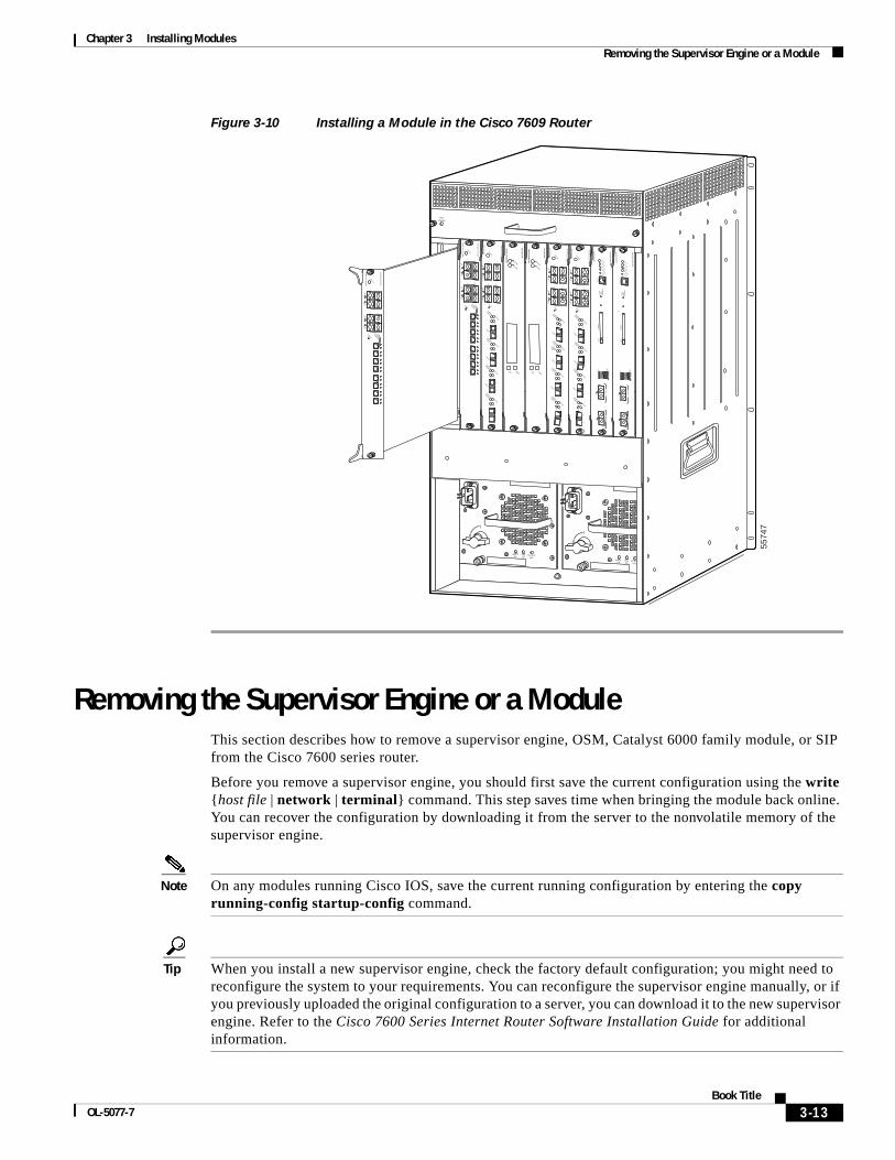
Chapter 3 Installing Modules Removing the Supervisor Engine or a Module
Figure 3-10 Installing a Module in the Cisco 7609 Router
Removing the Supervisor Engine or a ModuleThis section describes how to remove a supervisor engine, OSM, Catalyst 6000 family module, or SIP from the Cisco 7600 series router.
Before you remove a supervisor engine, you should first save the current configuration using the write {host file | network | terminal} command. This step saves time when bringing the module back online. You can recover the configuration by downloading it from the server to the nonvolatile memory of the supervisor engine.
Note On any modules running Cisco IOS, save the current running configuration by entering the copy running-config startup-config command.
Tip When you install a new supervisor engine, check the factory default configuration; you might need to reconfigure the system to your requirements. You can reconfigure the supervisor engine manually, or if you previously uploaded the original configuration to a server, you can download it to the new supervisor engine. Refer to the Cisco 7600 Series Internet Router Software Installation Guide for additional information.
INPUTOK
FANOK
OUTPUTFAIL
o
INPUTOK
FANOK
OUTPUTFAIL
o
FANSTATUS
5574
7
SU
PE
RV
ISO
R2
WS
-X6K
-SU
P2-2G
E
STATUSSYSTEMCONSO
LEPWR M
GM
T
RESET
CO
NS
OLE
CO
NS
OLE
PO
RT
MO
DE
PC
MC
IAE
JEC
T
PO
RT
1P
OR
T 2
Sw
itch Load 100%
1%
LINKLINK
SU
PE
RV
ISO
R2
WS
-X6K
-SU
P2-2G
E
STATUSSYSTEMCONSO
LEPWR M
GM
T
RESET
CO
NS
OLE
CO
NS
OLE
PO
RT
MO
DE
PC
MC
IAE
JEC
T
PO
RT
1P
OR
T 2
Sw
itch Load 100%
1%
LINKLINK
SW
ITC
H F
AB
RIC
MD
L STATUS
SELECT
NEXT
WS
-C6500-S
FM
ACTIVE
SW
ITC
H F
AB
RIC
MD
L STATUS
SELECT
NEXTW
S-C
6500-SF
M
ACTIVE
OC
12 PO
S M
M
OS
M-40C
12-PO
S-M
M
STATUS
12
34RESET
LINK1
LINK2
LINK3
LINK4
CARRIER
ALARM
ACTIVE
TXRX
TX
PORT 1
RX
CARRIER
ALARM
ACTIVE
TXRX
TX
PORT 2
RX
CARRIER
ALARM
ACTIVE
TXRX
TX
PORT 3
RX
CARRIER
ALARM
ACTIVE
TXRX
TX
RX
OC
12 PO
S M
M
OS
M-40C
12-PO
S-M
M
STATUS
12
34RESET
LINK1
LINK2
LINK3
LINK4
CARRIER
ALARM
ACTIVE
TXRX
TX
PORT 1
RX
CARRIER
ALARM
ACTIVE
TXRX
TX
PORT 2
RX
CARRIER
ALARM
ACTIVE
TXRX
TX
PORT 3
RX
CARRIER
ALARM
ACTIVE
TXRX
TX
RX
OC
12 PO
S M
M
OS
M-40C
12-PO
S-M
M
STATUS
12
34RESET
LINK1
LINK2
LINK3
LINK4
CARRIER
ALARM
ACTIVE
TXRX
TX
PORT 1
RX
CARRIER
ALARM
ACTIVE
TXRX
TX
PORT 2
RX
CARRIER
ALARM
ACTIVE
TXRX
TX
PORT 3
RX
CARRIER
ALARM
ACTIVE
TXRX
TX
RX
8 P
OR
T O
C3 P
OS
MM
OS
M-8
OC
3-P
OS
MM
STATUS
1
1
2
2
3
3
1
2
3
4
4
4
RESET
LINK
CARRIER
ALARM
LINK
LINK
LINK
LINK
5
6
7
8
8 P
OR
T O
C3 P
OS
MM
OS
M-8
OC
3-P
OS
MM
STATUS
1
1
2
2
3
3
1
2
3
4
4
4
RESET
LINK
CARRIER
ALARM
LINK
LINK
LINK
LINK
5
6
7
8
LINKCARRIER
ALARM
LINK
3-13Book Title
OL-5077-7
Chapter 3 Installing Modules Removing the Supervisor Engine or a Module
Caution To prevent ESD damage, handle modules by the carrier edges only.
Warning Hazardous voltage or energy is present on the backplane when the system is operating. Use caution when servicing.
Warning Invisible laser radiation may be emitted from disconnected fibers or connectors. Do not stare into beams or view directly with optical instruments.
To remove a supervisor engine or module, perform these steps:
Step 1 Disconnect any network interface cables attached to the supervisor engine or module.
Step 2 Verify that the captive installation screws on all of the modules in the chassis are tight. This step assures that the space created by the removed module is maintained.
Note If the captive installation screws are loose, the EMI gaskets on the installed modules will push the modules toward the open slot, reducing the opening size and making it difficult to install the replacement module.
Step 3 Loosen the two captive screws on the supervisor engine or module.
Step 4 Depending on the position of the slots in the chassis (horizontal or vertical), perform one of these two sets of steps:
Horizontal slots
a. Place your thumbs on the left and right ejector levers and simultaneously rotate the levers outward to unseat the module from the backplane connector.
b. Grasp the front edge of the module and slide the module part of the way out of the slot. Place your other hand under the module to support the weight of the module. Do not touch the module circuitry.
Vertical slots
a. Place your thumbs on the ejector levers located at the top and bottom of the module, and simultaneously rotate the levers outward to unseat the module from the backplane connector.
b. Grasp the edges of the module, and slide the module straight out of the slot. Do not touch the module circuitry.
Step 5 Place the module on an antistatic mat or antistatic foam, or immediately reinstall it in another slot.
Step 6 If the slot is to remain empty, install a module filler plate to keep dust out of the chassis and to maintain proper airflow through the chassis.
3-14Book Title
OL-5077-7
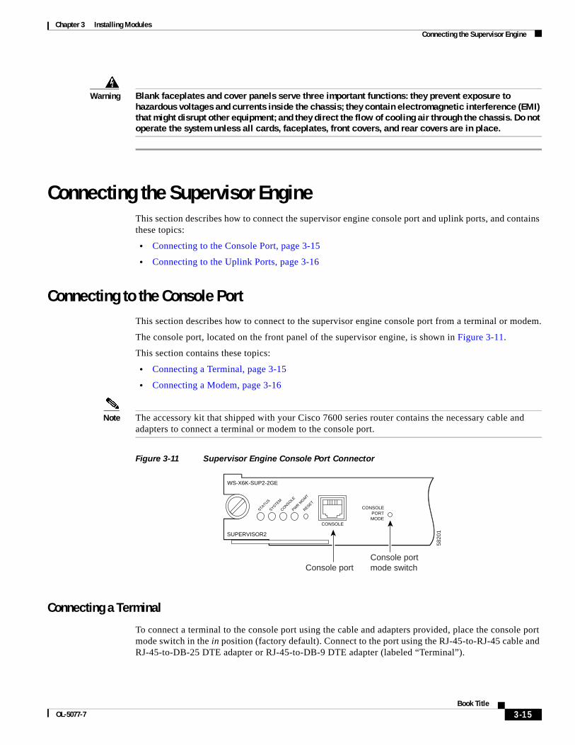
Chapter 3 Installing Modules Connecting the Supervisor Engine
Warning Blank faceplates and cover panels serve three important functions: they prevent exposure to hazardous voltages and currents inside the chassis; they contain electromagnetic interference (EMI) that might disrupt other equipment; and they direct the flow of cooling air through the chassis. Do not operate the system unless all cards, faceplates, front covers, and rear covers are in place.
Connecting the Supervisor EngineThis section describes how to connect the supervisor engine console port and uplink ports, and contains these topics:
• Connecting to the Console Port, page 3-15
• Connecting to the Uplink Ports, page 3-16
Connecting to the Console PortThis section describes how to connect to the supervisor engine console port from a terminal or modem.
The console port, located on the front panel of the supervisor engine, is shown in Figure 3-11.
This section contains these topics:
• Connecting a Terminal, page 3-15
• Connecting a Modem, page 3-16
Note The accessory kit that shipped with your Cisco 7600 series router contains the necessary cable and adapters to connect a terminal or modem to the console port.
Figure 3-11 Supervisor Engine Console Port Connector
Connecting a Terminal
To connect a terminal to the console port using the cable and adapters provided, place the console port mode switch in the in position (factory default). Connect to the port using the RJ-45-to-RJ-45 cable and RJ-45-to-DB-25 DTE adapter or RJ-45-to-DB-9 DTE adapter (labeled “Terminal”).
Console port mode switch
5820
1
Console port
SUPERVISOR2
WS-X6K-SUP2-2GE
STATUS
SYSTEM
CONSOLE
PWR M
GMT
RESET
CONSOLE
CONSOLEPORTMODE
3-15Book Title
OL-5077-7

Chapter 3 Installing Modules Connecting the Supervisor Engine
To connect a terminal using a Catalyst 5000 family Supervisor Engine III console cable, place the console port mode switch in the out position. Connect to the port using the Supervisor Engine III cable and the appropriate adapter for the terminal connection.
Check the terminal documentation to determine the baud rate. The baud rate of the terminal must match the default baud rate (9600 baud) of the console port. Set up the terminal as follows:
• 9600 baud
• 8 data bits
• No parity
• 2 stop bits
Connecting a Modem
To connect a modem to the console port, place the console port mode switch in the in position. Connect to the port using the RJ-45-to-RJ-45 cable and the RJ-45-to-DB-25 DCE adapter (labeled “Modem”).
Connecting to the Uplink PortsThis section describes how to connect to the supervisor engine uplink ports.
Note In a redundant configuration with two supervisor engines, the uplink ports on the redundant (standby) supervisor engine are active and can be used for normal traffic like any other ports in the chassis.
Warning Invisible laser radiation may be emitted from disconnected fibers or connectors. Do not stare into beams or view directly with optical instruments.
To connect to the supervisor engine uplink ports, perform these steps:
Step 1 Remove the plugs from the Gigabit Interface Converter (GBIC) optical bores; store them for future use.
Step 2 Remove the plugs from the SC connector (see Figure 3-12) on the fiber-optic cable.
Step 3 Insert the connector into the GBIC.
Note When you plug the SC connector into the GBIC, make sure that both the transmit (Tx) and receive (Rx) fiber-optic cables are fully inserted into the SC connector.
Note If you are using the LX/LH GBIC with MMF, you need to install a patch cord between the GBIC and the MMF cable. See the “Patch Cord” section on page 2-13 for details.
Caution Do not remove the plugs from the GBIC optical bores or the fiber-optic cable until you are ready to connect the cable. The plugs protect the GBIC optical bores and cable from contamination.
3-16Book Title
OL-5077-7
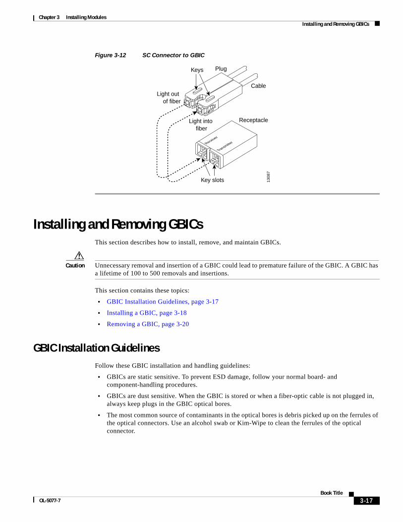
Chapter 3 Installing Modules Installing and Removing GBICs
Figure 3-12 SC Connector to GBIC
Installing and Removing GBICsThis section describes how to install, remove, and maintain GBICs.
Caution Unnecessary removal and insertion of a GBIC could lead to premature failure of the GBIC. A GBIC has a lifetime of 100 to 500 removals and insertions.
This section contains these topics:
• GBIC Installation Guidelines, page 3-17
• Installing a GBIC, page 3-18
• Removing a GBIC, page 3-20
GBIC Installation GuidelinesFollow these GBIC installation and handling guidelines:
• GBICs are static sensitive. To prevent ESD damage, follow your normal board- and component-handling procedures.
• GBICs are dust sensitive. When the GBIC is stored or when a fiber-optic cable is not plugged in, always keep plugs in the GBIC optical bores.
• The most common source of contaminants in the optical bores is debris picked up on the ferrules of the optical connectors. Use an alcohol swab or Kim-Wipe to clean the ferrules of the optical connector.
Cable
Plug
Receptacle
Keys
Receiver
Transmitter
Light out of fiber
Light into fiber
13087
Key slots
3-17Book Title
OL-5077-7

Chapter 3 Installing Modules Installing and Removing GBICs
Installing a GBICTwo physical GBIC models are available. One GBIC model has a locking handle to secure the GBIC in the module; the other model uses two clips, one on each side of the GBIC. This section contains the procedures for installing both GBIC models.
Installing a GBIC with Clips
Warning Invisible laser radiation may be emitted from disconnected fibers or connectors. Do not stare into beams or view directly with optical instruments.
To install a GBIC with clips, perform these steps:
Step 1 Remove the GBIC from its protective packaging.
Step 2 Check the label on the GBIC to verify that the GBIC is the correct model (SX, LX/LH, or ZX) for your network.
Step 3 Grip the sides of the GBIC with your thumb and forefinger and insert the GBIC into the module socket, as shown in Figure 3-13.
Note GBICs are keyed to prevent incorrect insertion.
Figure 3-13 Installing a GBIC with Clips
Step 4 Slide the GBIC through the flap covering the socket opening until you hear a click indicating the GBIC is locked into the slot.
Warning Invisible laser radiation may be emitted from disconnected fibers or connectors. Do not stare into beams or view directly with optical instruments.
LINK
5118
0
Plug
GBIC
Squeeze in clipsand slide GBICinto slot
3-18Book Title
OL-5077-7
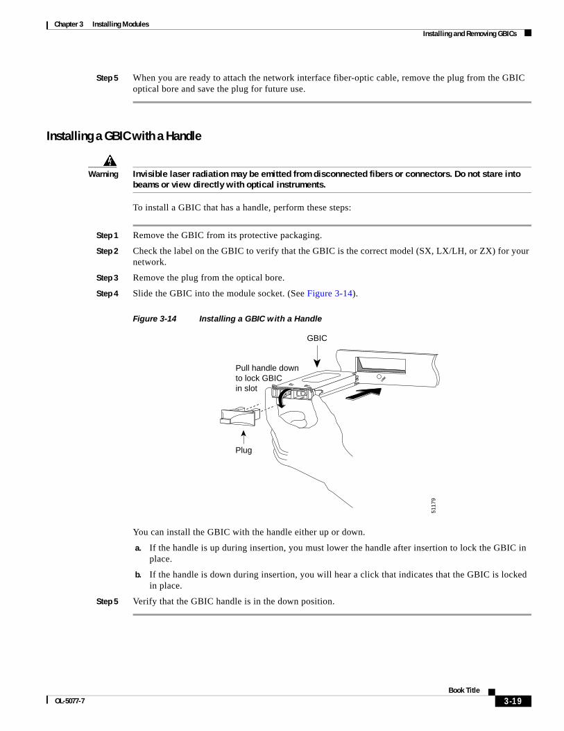
Chapter 3 Installing Modules Installing and Removing GBICs
Step 5 When you are ready to attach the network interface fiber-optic cable, remove the plug from the GBIC optical bore and save the plug for future use.
Installing a GBIC with a Handle
Warning Invisible laser radiation may be emitted from disconnected fibers or connectors. Do not stare into beams or view directly with optical instruments.
To install a GBIC that has a handle, perform these steps:
Step 1 Remove the GBIC from its protective packaging.
Step 2 Check the label on the GBIC to verify that the GBIC is the correct model (SX, LX/LH, or ZX) for your network.
Step 3 Remove the plug from the optical bore.
Step 4 Slide the GBIC into the module socket. (See Figure 3-14).
Figure 3-14 Installing a GBIC with a Handle
You can install the GBIC with the handle either up or down.
a. If the handle is up during insertion, you must lower the handle after insertion to lock the GBIC in place.
b. If the handle is down during insertion, you will hear a click that indicates that the GBIC is locked in place.
Step 5 Verify that the GBIC handle is in the down position.
LINK
Plug
Pull handle downto lock GBICin slot
5117
9
GBIC
3-19Book Title
OL-5077-7
Chapter 3 Installing Modules Using Flash PC Cards
Removing a GBICTwo physical GBIC models are available. One GBIC model has a locking handle to secure the GBIC in the module; the other model uses two clips, one on each side of the GBIC. This section contains procedures for removing both GBIC models.
Removing a GBIC with Clips
Warning Invisible laser radiation may be emitted from disconnected fibers or connectors. Do not stare into beams or view directly with optical instruments.
If you are removing a GBIC with clips, perform these steps:
Step 1 Disconnect the network fiber-optic cable from the GBIC SC connector.
Step 2 Release the GBIC from the slot by simultaneously squeezing the two plastic tabs (one on each side of the GBIC).
Step 3 Slide the GBIC out of the Gigabit Ethernet module slot. A flap drops down to protect the Gigabit Ethernet module connector.
Step 4 Place the GBIC in an antistatic bag.
Removing a GBIC with a Handle
Warning Invisible laser radiation may be emitted from disconnected fibers or connectors. Do not stare into beams or view directly with optical instruments.
If you are removing a GBIC with a handle, perform these steps:
Step 1 Disconnect the network fiber-optic cable from the GBIC SC connector.
Step 2 Rotate the handle up to release the GBIC from the slot.
Step 3 Grip the handle or the sides of the GBIC and slide the GBIC out of the slot. A flap drops down to protect the slot.
Step 4 Place the GBIC in an antistatic bag.
Using Flash PC Cards
Note To use a Flash PC card with the supervisor engine, you must format the card with the supervisor engine.
3-20Book Title
OL-5077-7
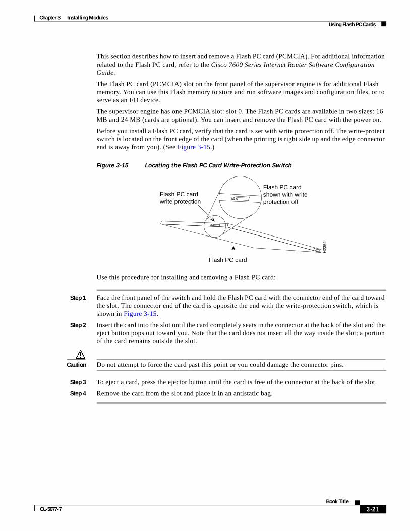
Chapter 3 Installing Modules Using Flash PC Cards
This section describes how to insert and remove a Flash PC card (PCMCIA). For additional information related to the Flash PC card, refer to the Cisco 7600 Series Internet Router Software Configuration Guide.
The Flash PC card (PCMCIA) slot on the front panel of the supervisor engine is for additional Flash memory. You can use this Flash memory to store and run software images and configuration files, or to serve as an I/O device.
The supervisor engine has one PCMCIA slot: slot 0. The Flash PC cards are available in two sizes: 16 MB and 24 MB (cards are optional). You can insert and remove the Flash PC card with the power on.
Before you install a Flash PC card, verify that the card is set with write protection off. The write-protect switch is located on the front edge of the card (when the printing is right side up and the edge connector end is away from you). (See Figure 3-15.)
Figure 3-15 Locating the Flash PC Card Write-Protection Switch
Use this procedure for installing and removing a Flash PC card:
Step 1 Face the front panel of the switch and hold the Flash PC card with the connector end of the card toward the slot. The connector end of the card is opposite the end with the write-protection switch, which is shown in Figure 3-15.
Step 2 Insert the card into the slot until the card completely seats in the connector at the back of the slot and the eject button pops out toward you. Note that the card does not insert all the way inside the slot; a portion of the card remains outside the slot.
Caution Do not attempt to force the card past this point or you could damage the connector pins.
Step 3 To eject a card, press the ejector button until the card is free of the connector at the back of the slot.
Step 4 Remove the card from the slot and place it in an antistatic bag.
Flash PC card
Flash PC card write protection
Flash PC card shown with writeprotection off
H23
52
3-21Book Title
OL-5077-7
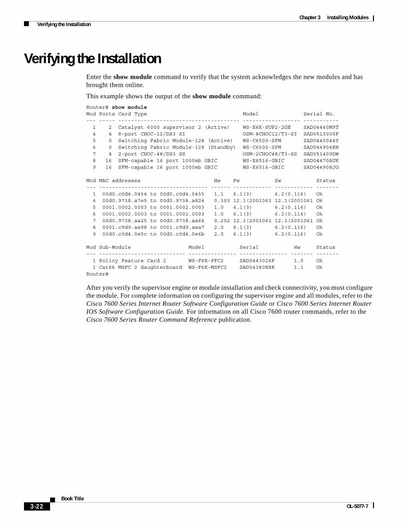
Chapter 3 Installing Modules Verifying the Installation
Verifying the InstallationEnter the show module command to verify that the system acknowledges the new modules and has brought them online.
This example shows the output of the show module command:
Router# show moduleMod Ports Card Type Model Serial No.--- ----- -------------------------------------- ------------------ ----------- 1 2 Catalyst 6000 supervisor 2 (Active) WS-X6K-SUP2-2GE SAD04460M9T 4 4 8-port CHOC-12/DS3 SI OSM-8CHOC12/T3-SI SAD0513000F 5 0 Switching Fabric Module-128 (Active) WS-C6500-SFM SAD0445044Y 6 0 Switching Fabric Module-128 (Standby) WS-C6500-SFM SAD044904RN 7 4 2-port CHOC-48/DS3 SS OSM-2CHOC48/T3-SS SAD051409DW 8 16 SFM-capable 16 port 1000mb GBIC WS-X6516-GBIC SAD04470AUK 9 16 SFM-capable 16 port 1000mb GBIC WS-X6516-GBIC SAD044908JG
Mod MAC addresses Hw Fw Sw Status--- ---------------------------------- ------ ------------ ------------ ------- 1 00d0.c0d4.0454 to 00d0.c0d4.0455 1.1 6.1(3) 6.2(0.116) Ok 4 00d0.9738.a7e5 to 00d0.9738.a824 0.303 12.1(2001061 12.1(2001061 Ok 5 0001.0002.0003 to 0001.0002.0003 1.0 6.1(3) 6.2(0.116) Ok 6 0001.0002.0003 to 0001.0002.0003 1.0 6.1(3) 6.2(0.116) Ok 7 00d0.9738.aa25 to 00d0.9738.aa64 0.202 12.1(2001061 12.1(2001061 Ok 8 0001.c9d9.aa98 to 0001.c9d9.aaa7 2.0 6.1(3) 6.2(0.116) Ok 9 00d0.c0d4.0e5c to 00d0.c0d4.0e6b 2.0 6.1(3) 6.2(0.116) Ok
Mod Sub-Module Model Serial Hw Status --- --------------------------- --------------- --------------- ------- ------- 1 Policy Feature Card 2 WS-F6K-PFC2 SAD0443026F 1.0 Ok 1 Cat6k MSFC 2 daughterboard WS-F6K-MSFC2 SAD04380K8K 1.1 Ok Router#
After you verify the supervisor engine or module installation and check connectivity, you must configure the module. For complete information on configuring the supervisor engine and all modules, refer to the Cisco 7600 Series Internet Router Software Configuration Guide or Cisco 7600 Series Internet Router IOS Software Configuration Guide. For information on all Cisco 7600 router commands, refer to the Cisco 7600 Series Router Command Reference publication.
3-22Book Title
OL-5077-7
OL-5077-7
C H A P T E R 4
TroubleshootingTroubleshooting Router Start Up IssuesWhen you start up a Cisco 7600 series router, the following occurs:
• The AC (or DC) OK LED is switched on and remains so till the system receives power.
• The blower is initiated.
• The supervisor and the front-panel Normal LEDs are enabled (to indicate normal system operation) and remain so during system operation.
• The LEDs enabled on each interface processor should be switched on (to indicate that the supervisor has completed initialization of the interface processor).
When the 7600 series system initializes successfully, the system banner should be displayed on the console screen. If not, make sure that the console terminal is properly connected to the supervisor console port and that the terminal is set correctly. The system banner should look like this:
System Bootstrap, Version 12.2(33r)SRD5, RELEASE SOFTWARE (fc1)Technical Support: http://www.cisco.com/techsupport
Copyright (c) 2009 by cisco Systems, Inc.
C7600-RSP720/SP platform with 1048576 Kbytes of main memory
Troubleshooting Router Booting IssuesCisco routers can initialize the system (boot) in these ways:
• Flash memory— A nonvolatile storage medium that can be electrically erased and reprogrammed.
• PC Flash memory card—A removable Flash memory card.
Troubleshooting Router Boot Failure from the Flash MemoryTable 4-1 outlines the solutions for boot failure from the flash memory.
Troubleshooting Vector Errors When Booting from Flash MemoryTable 4-2 outlines the solutions for vector errors when the router boots from the flash memory.
4-1Cisco 7600 Series Routers Module Guide
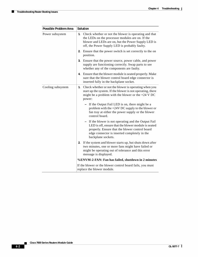
Chapter 4 TroubleshootingTroubleshooting Router Booting Issues
Possible Problem Area Solution
Power subsystem 1. Check whether or not the blower is operating and that the LEDs on the processor modules are on. If the blower and LEDs are on, but the Power Supply LED is off, the Power Supply LED is probably faulty.
2. Ensure that the power switch is set correctly to the on position.
3. Ensure that the power source, power cable, and power supply are functioning correctly. Swap parts to see whether any of the components are faulty.
4. Ensure that the blower module is seated properly. Make sure that the blower control board edge connector is inserted fully in the backplane socket.
Cooling subsystem 1. Check whether or not the blower is operating when you start up the system. If the blower is not operating, there might be a problem with the blower or the +24 V DC power:
– If the Output Fail LED is on, there might be a problem with the +24V DC supply to the blower or fan tray at either the power supply or the blower control board.
– If the blower is not operating and the Output Fail LED is off, ensure that the blower module is seated properly. Ensure that the blower control board edge connector is inserted completely in the backplane sockets.
2. If the system and blower starts up, but shuts down after two minutes, one or more fans might have failed or might be operating out of tolerance and this error message is displayed.
%ENVM-2-FAN: Fan has failed, shutdown in 2 minutes
If the blower or the blower control board fails, you must replace the blower module.
4-2Cisco 7600 Series Routers Module Guide
OL-5077-7
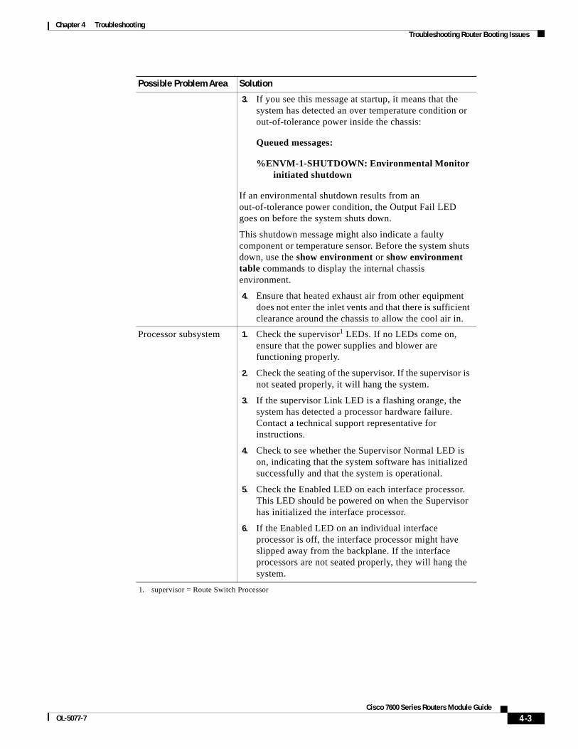
Chapter 4 TroubleshootingTroubleshooting Router Booting Issues
3. If you see this message at startup, it means that the system has detected an over temperature condition or out-of-tolerance power inside the chassis:
Queued messages:
%ENVM-1-SHUTDOWN: Environmental Monitor initiated shutdown
If an environmental shutdown results from an out-of-tolerance power condition, the Output Fail LED goes on before the system shuts down.
This shutdown message might also indicate a faulty component or temperature sensor. Before the system shuts down, use the show environment or show environment table commands to display the internal chassis environment.
4. Ensure that heated exhaust air from other equipment does not enter the inlet vents and that there is sufficient clearance around the chassis to allow the cool air in.
Processor subsystem 1. Check the supervisor1 LEDs. If no LEDs come on, ensure that the power supplies and blower are functioning properly.
2. Check the seating of the supervisor. If the supervisor is not seated properly, it will hang the system.
3. If the supervisor Link LED is a flashing orange, the system has detected a processor hardware failure. Contact a technical support representative for instructions.
4. Check to see whether the Supervisor Normal LED is on, indicating that the system software has initialized successfully and that the system is operational.
5. Check the Enabled LED on each interface processor. This LED should be powered on when the Supervisor has initialized the interface processor.
6. If the Enabled LED on an individual interface processor is off, the interface processor might have slipped away from the backplane. If the interface processors are not seated properly, they will hang the system.
1. supervisor = Route Switch Processor
Possible Problem Area Solution
4-3Cisco 7600 Series Routers Module Guide
OL-5077-7
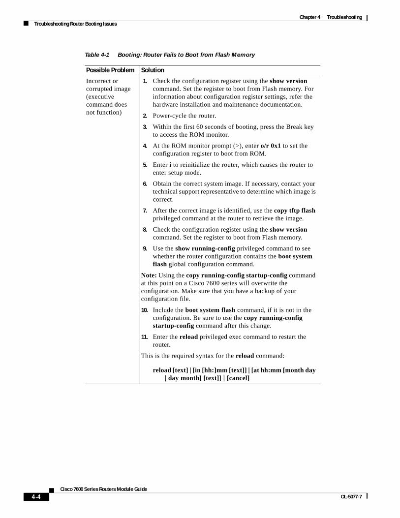
Chapter 4 TroubleshootingTroubleshooting Router Booting Issues
Table 4-1 Booting: Router Fails to Boot from Flash Memory
Possible Problem Solution
Incorrect or corrupted image (executive command does not function)
1. Check the configuration register using the show version command. Set the register to boot from Flash memory. For information about configuration register settings, refer the hardware installation and maintenance documentation.
2. Power-cycle the router.
3. Within the first 60 seconds of booting, press the Break key to access the ROM monitor.
4. At the ROM monitor prompt (>), enter o/r 0x1 to set the configuration register to boot from ROM.
5. Enter i to reinitialize the router, which causes the router to enter setup mode.
6. Obtain the correct system image. If necessary, contact your technical support representative to determine which image is correct.
7. After the correct image is identified, use the copy tftp flash privileged command at the router to retrieve the image.
8. Check the configuration register using the show version command. Set the register to boot from Flash memory.
9. Use the show running-config privileged command to see whether the router configuration contains the boot system flash global configuration command.
Note: Using the copy running-config startup-config command at this point on a Cisco 7600 series will overwrite the configuration. Make sure that you have a backup of your configuration file.
10. Include the boot system flash command, if it is not in the configuration. Be sure to use the copy running-config startup-config command after this change.
11. Enter the reload privileged exec command to restart the router.
This is the required syntax for the reload command:
reload [text] | [in [hh:]mm [text]] | [at hh:mm [month day | day month] [text]] | [cancel]
4-4Cisco 7600 Series Routers Module Guide
OL-5077-7
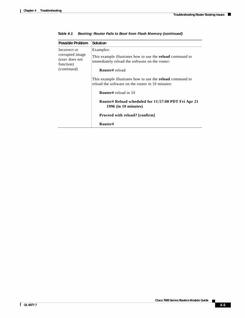
Chapter 4 TroubleshootingTroubleshooting Router Booting Issues
Incorrect or corrupted image (exec does not function) (continued)
Examples:
This example illustrates how to use the reload command to immediately reload the software on the router:
Router# reload
This example illustrates how to use the reload command to reload the software on the router in 10 minutes:
Router# reload in 10
Router# Reload scheduled for 11:57:08 PDT Fri Apr 21 1996 (in 10 minutes)
Proceed with reload? [confirm]
Router#
Table 4-1 Booting: Router Fails to Boot from Flash Memory (continued)
Possible Problem Solution
4-5Cisco 7600 Series Routers Module Guide
OL-5077-7

Chapter 4 TroubleshootingTroubleshooting Router Booting Issues
Incorrect or corrupted image (exec functions)
1. Obtain the correct system image. If necessary, contact your technical support representative to determine which image is appropriate.
2. Use the copy tftp flash privileged exec command to retrieve the image.
3. Check the configuration register using the show version exec command. Set the register to boot from Flash memory. For information about configuration register settings, refer to your hardware installation and maintenance documentation.
4. Use the show running-config privileged exec command to determine whether the active configuration contains the boot system flash global configuration command. Use the show startup-config privileged exec command to determine whether the boot system flash command is included in the configuration stored in NVRAM1.
5. Include the boot system flash command, if it is not in the configuration. Be sure to use the copy running-config startup-config privileged exec command to save your modification after this change.
6. Enter the reload privileged exec command to restart the router.
This is the required syntx for the reload command:
reload [text] | [in [hh:]mm [text]] | [at hh:mm [month day | day month] [text]] | [cancel]
Examples:
The following example illustrates how to use the reload command to immediately reload the software on the router:
Router# reload
Incorrect or corrupted image (exec functions) (continued)
The following example illustrates how to use the reload command to reload the software on the router in 10 minutes:
Router# reload in 10
Router# Reload scheduled for 11:57:08 PDT Fri Apr 21 1996 (in 10 minutes)
Proceed with reload? [confirm]
Router#
1. NVRAM = nonvolatile random-access memory
Table 4-1 Booting: Router Fails to Boot from Flash Memory (continued)
Possible Problem Solution
4-6Cisco 7600 Series Routers Module Guide
OL-5077-7

Chapter 4 TroubleshootingTroubleshooting Router Booting Issues
Table 4-2 Booting: Vector Error Occurs When Booting from Flash Memory
Possible Problem Solution
Compressed system image
1. Power-cycle the router.
2. Within the first 60 seconds of booting, press the Break key to access the ROM monitor.
3. At the ROM monitor prompt (>), enter o/r to set the configuration register to boot from ROM.
4. Enter b to boot the router. The router enters setup mode.
5. Press Ctrl-C to bypass the setup.
6. Enter the configure memory privileged command.
7. Obtain an uncompressed system image. From the router prompt, use the privileged command copy flash tftp to send the compressed image back to the TFTP1 server.
Decompress the image at the TFTP server, since this is not possible at the router side.
8. Use the copy tftp flash privileged command at the router to retrieve the uncompressed image. The following is an example of the use of the copy tftp flash command:
router# copy flash tftp filename
4-7Cisco 7600 Series Routers Module Guide
OL-5077-7
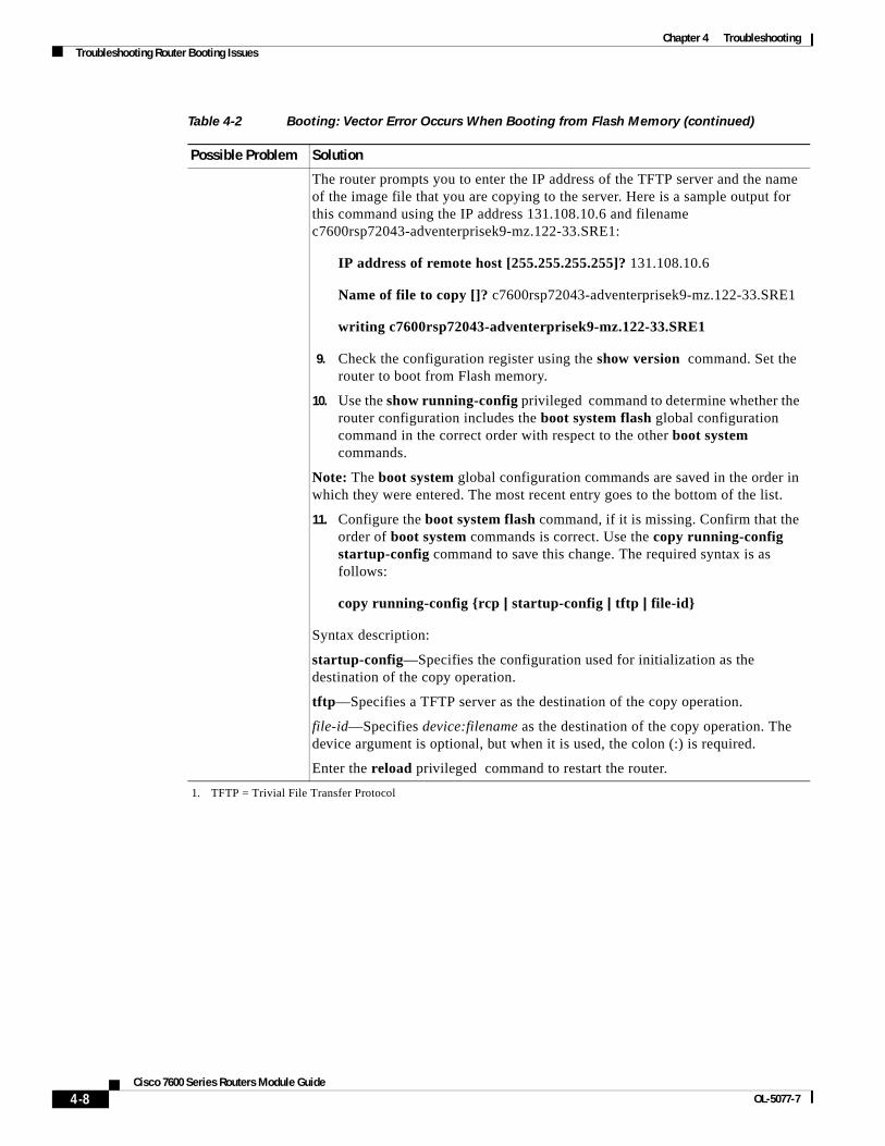
Chapter 4 TroubleshootingTroubleshooting Router Booting Issues
The router prompts you to enter the IP address of the TFTP server and the name of the image file that you are copying to the server. Here is a sample output for this command using the IP address 131.108.10.6 and filename c7600rsp72043-adventerprisek9-mz.122-33.SRE1:
IP address of remote host [255.255.255.255]? 131.108.10.6
Name of file to copy []? c7600rsp72043-adventerprisek9-mz.122-33.SRE1
writing c7600rsp72043-adventerprisek9-mz.122-33.SRE1
9. Check the configuration register using the show version command. Set the router to boot from Flash memory.
10. Use the show running-config privileged command to determine whether the router configuration includes the boot system flash global configuration command in the correct order with respect to the other boot system commands.
Note: The boot system global configuration commands are saved in the order in which they were entered. The most recent entry goes to the bottom of the list.
11. Configure the boot system flash command, if it is missing. Confirm that the order of boot system commands is correct. Use the copy running-config startup-config command to save this change. The required syntax is as follows:
copy running-config {rcp | startup-config | tftp | file-id}
Syntax description:
startup-config—Specifies the configuration used for initialization as the destination of the copy operation.
tftp—Specifies a TFTP server as the destination of the copy operation.
file-id—Specifies device:filename as the destination of the copy operation. The device argument is optional, but when it is used, the colon (:) is required.
Enter the reload privileged command to restart the router.
1. TFTP = Trivial File Transfer Protocol
Table 4-2 Booting: Vector Error Occurs When Booting from Flash Memory (continued)
Possible Problem Solution
4-8Cisco 7600 Series Routers Module Guide
OL-5077-7

Chapter 4 TroubleshootingTroubleshooting Router Booting Issues
Router Partially Boots from Flash and Displays Boot PromptTable 4-3 describes the solutions for a partial reboot of the router from the flash memory.
4-9Cisco 7600 Series Routers Module Guide
OL-5077-7

Chapter 4 TroubleshootingTroubleshooting Router Booting Issues
Table 4-3 Booting: Router Partially Boots from Flash and Displays Boot Prompt
Possible Problem Solution
No system image in Flash memory
1. Use the show flash command to determine whether an image exists in Flash memory.
2. If no image exists, use the copy tftp flash privileged command to copy the system image from your TFTP1 server to the router’s Flash memory. This is an example of the copy tftp flash command:
router# copy flash tftp filename
The router asks you for the IP address of the TFTP server and the name of the image file that you are copying to the server. A sample of the output for this command using IP address 131.108.10.6 and filename c7600rsp72043-adventerprisek9-mz.122-33.SRE1 follows:
IP address of remote host [255.255.255.255]? 131.108.10.6
Name of file to copy []? c7600rsp72043-adventerprisek9-mz.122-33.SRE1
writing c7600rsp72043-adventerprisek9-mz.122-33.SRE1 !!!!!!!!!!!!!!!!!!!!!!!!!!!!!!!!!!!!!!!!!
router#
3. Enter the reload privileged command to reboot the router.
Syntax:
This is the syntax for the reload command:
reload [text] | [in [hh:]mm [text]] | [at hh:mm [month day | day month] [text]] | [cancel]
Examples:
This illustrates how to use the reload command to immediately reload the software on the router:
Router# reload
This illustrates how to use the reload command to reload the software on the router in 10 minutes:
Router# reload in 10
Router# Reload scheduled for 11:57:08 PDT Fri Apr 21 1996 (in 10 minutes)
Proceed with reload? [confirm]
4-10Cisco 7600 Series Routers Module Guide
OL-5077-7
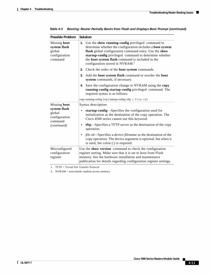
Chapter 4 TroubleshootingTroubleshooting Router Booting Issues
Missing boot system flash global configuration command
1. Use the show running-config privileged command to determine whether the configuration includes a boot system flash global configuration command entry. Use the show startup-config privileged command to determine whether the boot system flash command is included in the configuration stored in NVRAM.2
2. Check the order of the boot system commands.
3. Add the boot system flash command or reorder the boot system commands, if necessary.
4. Save the configuration change to NVRAM using the copy running-config startup-config privileged command. The required syntax is as follows:
copy running-config {rcp | startup-config | tftp | file-id}
Missing boot system flash global configuration command (continued)
Syntax description:
• startup-config—Specifies the configuration used for initialization as the destination of the copy operation. The Cisco 4500 series cannot use this keyword.
• tftp—Specifies a TFTP server as the destination of the copy operation.
• file-id—Specifies a device:filename as the destination of the copy operation. The device argument is optional, but when it is used, the colon (:) is required.
Misconfigured configuration register
Use the show version command to check the configuration register setting. Make sure that it is set to boot from Flash memory. See the hardware installation and maintenance publication for details regarding configuration register settings.
1. TFTP = Trivial File Transfer Protocol
2. NVRAM = nonvolatile random-access memory
Table 4-3 Booting: Router Partially Boots from Flash and Displays Boot Prompt (continued)
Possible Problem Solution
4-11Cisco 7600 Series Routers Module Guide
OL-5077-7
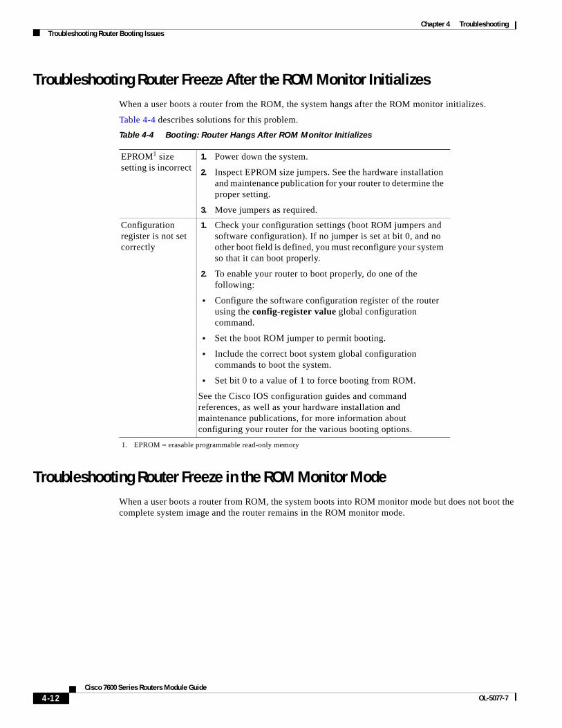
Chapter 4 TroubleshootingTroubleshooting Router Booting Issues
Troubleshooting Router Freeze After the ROM Monitor InitializesWhen a user boots a router from the ROM, the system hangs after the ROM monitor initializes.
Table 4-4 describes solutions for this problem.
Troubleshooting Router Freeze in the ROM Monitor ModeWhen a user boots a router from ROM, the system boots into ROM monitor mode but does not boot the complete system image and the router remains in the ROM monitor mode.
Table 4-4 Booting: Router Hangs After ROM Monitor Initializes
EPROM1 size setting is incorrect
1. Power down the system.
2. Inspect EPROM size jumpers. See the hardware installation and maintenance publication for your router to determine the proper setting.
3. Move jumpers as required.
Configuration register is not set correctly
1. Check your configuration settings (boot ROM jumpers and software configuration). If no jumper is set at bit 0, and no other boot field is defined, you must reconfigure your system so that it can boot properly.
2. To enable your router to boot properly, do one of the following:
• Configure the software configuration register of the router using the config-register value global configuration command.
• Set the boot ROM jumper to permit booting.
• Include the correct boot system global configuration commands to boot the system.
• Set bit 0 to a value of 1 to force booting from ROM.
See the Cisco IOS configuration guides and command references, as well as your hardware installation and maintenance publications, for more information about configuring your router for the various booting options.
1. EPROM = erasable programmable read-only memory
4-12Cisco 7600 Series Routers Module Guide
OL-5077-7
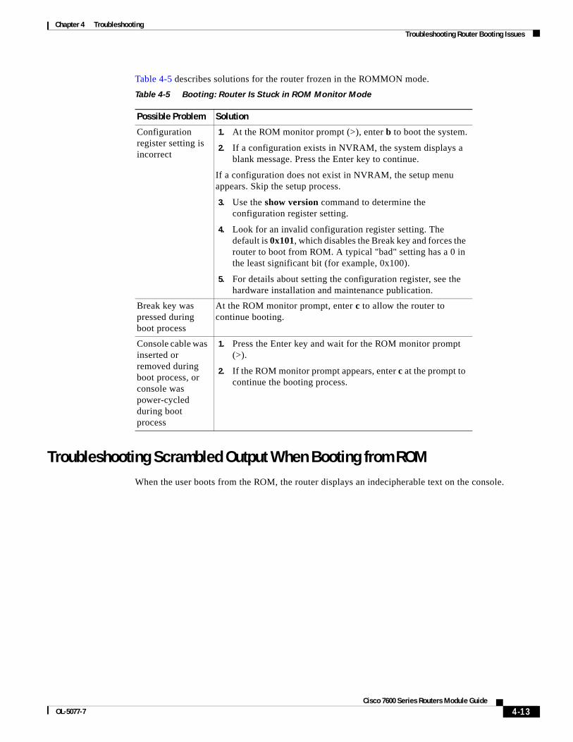
Chapter 4 TroubleshootingTroubleshooting Router Booting Issues
Table 4-5 describes solutions for the router frozen in the ROMMON mode.
Troubleshooting Scrambled Output When Booting from ROMWhen the user boots from the ROM, the router displays an indecipherable text on the console.
Table 4-5 Booting: Router Is Stuck in ROM Monitor Mode
Possible Problem Solution
Configuration register setting is incorrect
1. At the ROM monitor prompt (>), enter b to boot the system.
2. If a configuration exists in NVRAM, the system displays a blank message. Press the Enter key to continue.
If a configuration does not exist in NVRAM, the setup menu appears. Skip the setup process.
3. Use the show version command to determine the configuration register setting.
4. Look for an invalid configuration register setting. The default is 0x101, which disables the Break key and forces the router to boot from ROM. A typical "bad" setting has a 0 in the least significant bit (for example, 0x100).
5. For details about setting the configuration register, see the hardware installation and maintenance publication.
Break key was pressed during boot process
At the ROM monitor prompt, enter c to allow the router to continue booting.
Console cable was inserted or removed during boot process, or console was power-cycled during boot process
1. Press the Enter key and wait for the ROM monitor prompt (>).
2. If the ROM monitor prompt appears, enter c at the prompt to continue the booting process.
4-13Cisco 7600 Series Routers Module Guide
OL-5077-7
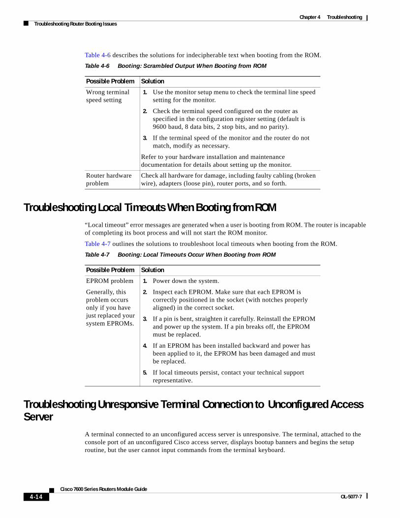
Chapter 4 TroubleshootingTroubleshooting Router Booting Issues
Table 4-6 describes the solutions for indecipherable text when booting from the ROM.
Troubleshooting Local Timeouts When Booting from ROM“Local timeout” error messages are generated when a user is booting from ROM. The router is incapable of completing its boot process and will not start the ROM monitor.
Table 4-7 outlines the solutions to troubleshoot local timeouts when booting from the ROM.
Troubleshooting Unresponsive Terminal Connection to Unconfigured Access Server
A terminal connected to an unconfigured access server is unresponsive. The terminal, attached to the console port of an unconfigured Cisco access server, displays bootup banners and begins the setup routine, but the user cannot input commands from the terminal keyboard.
Table 4-6 Booting: Scrambled Output When Booting from ROM
Possible Problem Solution
Wrong terminal speed setting
1. Use the monitor setup menu to check the terminal line speed setting for the monitor.
2. Check the terminal speed configured on the router as specified in the configuration register setting (default is 9600 baud, 8 data bits, 2 stop bits, and no parity).
3. If the terminal speed of the monitor and the router do not match, modify as necessary.
Refer to your hardware installation and maintenance documentation for details about setting up the monitor.
Router hardware problem
Check all hardware for damage, including faulty cabling (broken wire), adapters (loose pin), router ports, and so forth.
Table 4-7 Booting: Local Timeouts Occur When Booting from ROM
Possible Problem Solution
EPROM problem
Generally, this problem occurs only if you have just replaced your system EPROMs.
1. Power down the system.
2. Inspect each EPROM. Make sure that each EPROM is correctly positioned in the socket (with notches properly aligned) in the correct socket.
3. If a pin is bent, straighten it carefully. Reinstall the EPROM and power up the system. If a pin breaks off, the EPROM must be replaced.
4. If an EPROM has been installed backward and power has been applied to it, the EPROM has been damaged and must be replaced.
5. If local timeouts persist, contact your technical support representative.
4-14Cisco 7600 Series Routers Module Guide
OL-5077-7
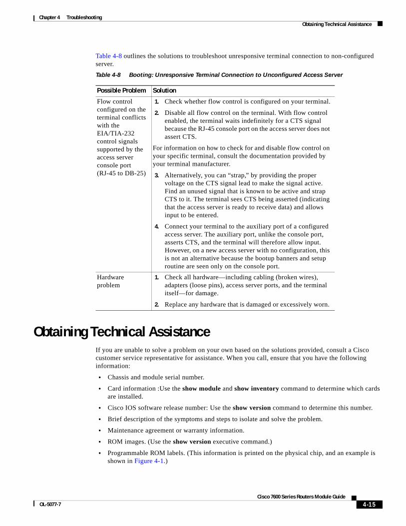
Chapter 4 TroubleshootingObtaining Technical Assistance
Table 4-8 outlines the solutions to troubleshoot unresponsive terminal connection to non-configured server.
Obtaining Technical AssistanceIf you are unable to solve a problem on your own based on the solutions provided, consult a Cisco customer service representative for assistance. When you call, ensure that you have the following information:
• Chassis and module serial number.
• Card information :Use the show module and show inventory command to determine which cards are installed.
• Cisco IOS software release number: Use the show version command to determine this number.
• Brief description of the symptoms and steps to isolate and solve the problem.
• Maintenance agreement or warranty information.
• ROM images. (Use the show version executive command.)
• Programmable ROM labels. (This information is printed on the physical chip, and an example is shown in Figure 4-1.)
Table 4-8 Booting: Unresponsive Terminal Connection to Unconfigured Access Server
Possible Problem Solution
Flow control configured on the terminal conflicts with the EIA/TIA-232 control signals supported by the access server console port (RJ-45 to DB-25)
1. Check whether flow control is configured on your terminal.
2. Disable all flow control on the terminal. With flow control enabled, the terminal waits indefinitely for a CTS signal because the RJ-45 console port on the access server does not assert CTS.
For information on how to check for and disable flow control on your specific terminal, consult the documentation provided by your terminal manufacturer.
3. Alternatively, you can “strap,” by providing the proper voltage on the CTS signal lead to make the signal active. Find an unused signal that is known to be active and strap CTS to it. The terminal sees CTS being asserted (indicating that the access server is ready to receive data) and allows input to be entered.
4. Connect your terminal to the auxiliary port of a configured access server. The auxiliary port, unlike the console port, asserts CTS, and the terminal will therefore allow input. However, on a new access server with no configuration, this is not an alternative because the bootup banners and setup routine are seen only on the console port.
Hardware problem
1. Check all hardware—including cabling (broken wires), adapters (loose pins), access server ports, and the terminal itself—for damage.
2. Replace any hardware that is damaged or excessively worn.
4-15Cisco 7600 Series Routers Module Guide
OL-5077-7

Chapter 4 TroubleshootingObtaining Technical Assistance
Figure 4-1 An Example of a Boot ROM Label—Boot ROM Version 12.2(33r)SRD5
• NVRAM configurations for client and adjacent routers.
• Debugging output from adjacent routers using the following privileged executive commands:
– debug ip packet
– debug arp
– debug ip udp
– debug tftp
U30 v12.2(33r)SRD5ROMMON
O17-2111-04Cisco Systems
4-16Cisco 7600 Series Routers Module Guide
OL-5077-7
OL-5077-7
A
P P E N D I X A Technical SpecificationsThis appendix provides the technical specifications for the OSMs, recommended Catalyst 6000 family modules, and SPA interface processors (SIPs).
• Module Specifications, page A-1
• Regulatory Standards Compliance, page A-2
Module SpecificationsTable A-1 lists the environmental and physical specifications for the OSMs and recommended Catalyst 6000 family modules.
Table A-2 lists the environmental and physical specifications for the SIPs.
Table A-1 Environmental and Physical Specifications
Item Specification
Environmental
Temperature, ambient operating 32°F (0°C) to 104°F (40°C)
Temperature, ambient nonoperating and storage
–40°F (–4.44°C) to 167°F (75°C)
Humidity (RH), ambient (noncondensing) operating
10% to 90%
Altitude operating –197 to 6500 feet (–60 to 2000 m)
Physical Characteristics
Dimensions (H x W x D) 1.2 x 14.4 x 16 inches (3.0 x 35.6 x 40.6 cm)
Weight 3 to 10 pounds (1.4 to 4.5 kg)
Table A-2 SIP Environmental and Physical Specifications
Item Specification
Physical Characteristics
Physical dimensions The SIP occupies one module slot and can be operated in Cisco 7600 series routers.
A-1Book Title

Appendix A Technical Specifications Regulatory Standards Compliance
Regulatory Standards ComplianceCisco 7600 series routers comply with the regulatory standards listed in the Regulatory Compliance and Safety Information for the Cisco 7600 Series Routers document.
Shipping weight 8 lb (3.64 kg)
Environmental
Operating temperature 32 to 104°F (0 to 40°C)
Relative humidity 10 to 90 percent, noncondensing
Storage temperature –4 to 149°F (–20 to 65°C)
Table A-2 SIP Environmental and Physical Specifications (continued)
Item Specification
A-2Book Title
OL-5077-7
OL-5077-7
A
P P E N D I X B Cable SpecificationsThis appendix lists the cable specifications for supported modules on the Cisco 7600 series router. The following signal summaries are contained in this appendix:
• Interface Specifications, page B-1
• Fiber-Optic Specifications, page B-1
• Switching Module RJ-45 10/100BASE-TX Ports, page B-2
• Supervisor Engine 2 Console Port Signals and Pinouts, page B-2
Interface SpecificationsTable B-1 lists the interface specifications for the OSMs.
Fiber-Optic SpecificationsThe specification for optical fiber transmission defines two types of fiber: single-mode and multimode. Within the single-mode category, three transmission types are defined: short reach, intermediate reach, and long reach. Within the multimode category, only short reach is available. Specifications for OC-3, OC-12, OC-48, and Gigabit Ethernet are in the “Determining Cable Distances” section on page 2-10.
Table B-1 Cisco 7600 OSM Interface Specifications
Cisco 7600 OSMsPhysical Layer Interface Mbps per Interface
Interface (Quantity and Type)
1-port and 2-port channelized OC-48
OC-48 2488.320 Mbps; full duplex
1 or 2 LC-type connectors
2-port and 4-port OC-12 POS
OC-12c 622.080 Mbps; full duplex
2 or 4 SC-type connectors
4-port and 8-port channelized OC-12
OC-12 622.080 Mbps; full duplex
4 or 8 LC-type connectors
8-port and 16-port OC-3 POS
OC-3c 155.520 Mbps; full duplex
8 or 16 MT-RJ connectors
2-port OC-12 ATM OC-12c 622.080 Mbps; full duplex
2 SC-type connectors
B-1Book Title

Appendix B Cable Specifications Switching Module RJ-45 10/100BASE-TX Ports
Switching Module RJ-45 10/100BASE-TX PortsTable B-2 lists the signals for the RJ-45 10/100BASE-TX ports. The receive and transmit signals are polarized. One pin of each signal pair carries the positive (+) signal, and the other pin carries the negative (–) signal.
Note Table B-2 lists the signals for the RJ-45 10/100BASE-TX connector, not the pinouts of the cable connecting to the port.
Supervisor Engine 2 Console Port Signals and PinoutsThe Cisco 7600 series router comes with an accessories box that contains the cable and adapters you need to connect a console (an ASCII terminal or PC running terminal emulation software) or modem to the console port. The accessories box includes these items:
• RJ-45-to-RJ-45 rollover cable
• RJ-45-to-DB-9 female DTE adapter (labeled “Terminal”)
• RJ-45-to-DB-25 female DTE adapter (labeled “Terminal”)
• RJ-45-to-DB-25 male DCE adapter (labeled “Modem”)
This cable and these adapters also ship with the Cisco 2500 series routers and other Cisco products.
Console Port Mode SwitchThe Supervisor Engine 2 front-panel console port mode switch allows you to connect a terminal or modem to the console port as follows:
Note Use a ballpoint pen tip or other small, pointed object to access the console port mode switch. The switch is shipped in the in position.
• Mode 1—Switch in the in position. Use this mode to connect a terminal to the console port using the RJ-45-to-RJ-45 rollover cable and DTE adapter (labeled “Terminal”).
Table B-2 RJ-45 10/100BASE-TX Signals
Pin Signal Description
1 RxD (+) Receive Data (+)
2 RxD (–) Receive Data (–)
3 TxD (+) Transmit Data (+)
4 NC No Connection
5 NC No Connection
6 TxD (–) Transmit Data (–)
7 NC No Connection
8 NC No Connection
B-2Book Title
OL-5077-7
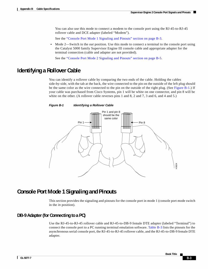
Appendix B Cable Specifications Supervisor Engine 2 Console Port Signals and Pinouts
You can also use this mode to connect a modem to the console port using the RJ-45-to-RJ-45 rollover cable and DCE adapter (labeled “Modem”).
See the “Console Port Mode 1 Signaling and Pinouts” section on page B-3.
• Mode 2—Switch in the out position. Use this mode to connect a terminal to the console port using the Catalyst 5000 family Supervisor Engine III console cable and appropriate adapter for the terminal connection (cable and adapter are not provided).
See the “Console Port Mode 2 Signaling and Pinouts” section on page B-5.
Identifying a Rollover CableYou can identify a rollover cable by comparing the two ends of the cable. Holding the cables side-by-side, with the tab at the back, the wire connected to the pin on the outside of the left plug should be the same color as the wire connected to the pin on the outside of the right plug. (See Figure B-1.) If your cable was purchased from Cisco Systems, pin 1 will be white on one connector, and pin 8 will be white on the other. (A rollover cable reverses pins 1 and 8, 2 and 7, 3 and 6, and 4 and 5.)
Figure B-1 Identifying a Rollover Cable
Console Port Mode 1 Signaling and PinoutsThis section provides the signaling and pinouts for the console port in mode 1 (console port mode switch in the in position).
DB-9 Adapter (for Connecting to a PC)
Use the RJ-45-to-RJ-45 rollover cable and RJ-45-to-DB-9 female DTE adapter (labeled “Terminal”) to connect the console port to a PC running terminal emulation software. Table B-3 lists the pinouts for the asynchronous serial console port, the RJ-45-to-RJ-45 rollover cable, and the RJ-45-to-DB-9 female DTE adapter.
Pin 1 Pin 8
H38
24
Pin 1 and pin 8should be the
same color
B-3Book Title
OL-5077-7
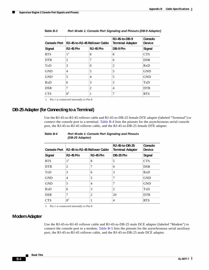
Appendix B Cable Specifications Supervisor Engine 2 Console Port Signals and Pinouts
DB-25 Adapter (for Connecting to a Terminal)
Use the RJ-45-to-RJ-45 rollover cable and RJ-45-to-DB-25 female DTE adapter (labeled “Terminal”) to connect the console port to a terminal. Table B-4 lists the pinouts for the asynchronous serial console port, the RJ-45-to-RJ-45 rollover cable, and the RJ-45-to-DB-25 female DTE adapter.
Modem Adapter
Use the RJ-45-to-RJ-45 rollover cable and RJ-45-to-DB-25 male DCE adapter (labeled “Modem”) to connect the console port to a modem. Table B-5 lists the pinouts for the asynchronous serial auxiliary port, the RJ-45-to-RJ-45 rollover cable, and the RJ-45-to-DB-25 male DCE adapter.
Table B-3 Port Mode 1: Console Port Signaling and Pinouts (DB-9 Adapter)
Console Port RJ-45-to-RJ-45 Rollover CableRJ-45-to-DB-9 Terminal Adapter
ConsoleDevice
Signal RJ-45 Pin RJ-45 Pin DB-9 Pin Signal
RTS 11
1. Pin 1 is connected internally to Pin 8.
8 8 CTS
DTR 2 7 6 DSR
TxD 3 6 2 RxD
GND 4 5 5 GND
GND 5 4 5 GND
RxD 6 3 3 TxD
DSR 7 2 4 DTR
CTS 81 1 7 RTS
Table B-4 Port Mode 1: Console Port Signaling and Pinouts (DB-25 Adapter)
Console Port RJ-45-to-RJ-45 Rollover Cable RJ-45-to-DB-25 Terminal Adapter
ConsoleDevice
Signal RJ-45 Pin RJ-45 Pin DB-25 Pin Signal
RTS 11
1. Pin 1 is connected internally to Pin 8.
8 5 CTS
DTR 2 7 6 DSR
TxD 3 6 3 RxD
GND 4 5 7 GND
GND 5 4 7 GND
RxD 6 3 2 TxD
DSR 7 2 20 DTR
CTS 81 1 4 RTS
B-4Book Title
OL-5077-7
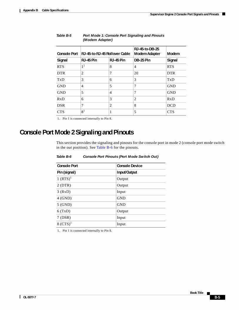
Appendix B Cable Specifications Supervisor Engine 2 Console Port Signals and Pinouts
Console Port Mode 2 Signaling and PinoutsThis section provides the signaling and pinouts for the console port in mode 2 (console port mode switch in the out position). See Table B-6 for the pinouts.
Table B-5 Port Mode 1: Console Port Signaling and Pinouts (Modem Adapter)
Console Port RJ-45-to-RJ-45 Rollover CableRJ-45-to-DB-25 Modem Adapter Modem
Signal RJ-45 Pin RJ-45 Pin DB-25 Pin Signal
RTS 11
1. Pin 1 is connected internally to Pin 8.
8 4 RTS
DTR 2 7 20 DTR
TxD 3 6 3 TxD
GND 4 5 7 GND
GND 5 4 7 GND
RxD 6 3 2 RxD
DSR 7 2 8 DCD
CTS 81 1 5 CTS
Table B-6 Console Port Pinouts (Port Mode Switch Out)
Console Port Console Device
Pin (signal) Input/Output
1 (RTS)1
1. Pin 1 is connected internally to Pin 8.
Output
2 (DTR) Output
3 (RxD) Input
4 (GND) GND
5 (GND) GND
6 (TxD) Output
7 (DSR) Input
8 (CTS)1 Input
B-5Book Title
OL-5077-7

Appendix B Cable Specifications Supervisor Engine 2 Console Port Signals and Pinouts
B-6Book Title
OL-5077-7

OL-5077-7
A
P P E N D I X C Upgrading the Memory on the OSMThis appendix provides procedures for upgrading the memory on the Optical Services Modules (OSMs).
This appendix contains these sections:
• Safety, page C-1
• Required Tools, page C-3
• Upgrading the OSM Memory, page C-3
SafetySafety warnings appear throughout this section in procedures that may harm you if performed incorrectly. A warning symbol precedes each warning statement.
Warning This warning symbol means danger. You are in a situation that could cause bodily injury. Before you work on any equipment, be aware of the hazards involved with electrical circuitry and be familiar with standard practices for preventing accidents. To see translations of the warnings that appear in this publication, refer to the Regulatory Compliance and Safety Information document that accompanied this device.
Wrist Strap Warning
Warning During this procedure, wear grounding wrist straps to avoid ESD damage to the card. Do not directly touch the backplane with your hand or any metal tool, or you could shock yourself. Statement 94
Waarschuwing Draag tijdens deze procedure aardingspolsbanden om te vermijden dat de kaart beschadigd wordt door elektrostatische ontlading. Raak het achterbord niet rechtstreeks aan met uw hand of met een metalen werktuig, omdat u anders een elektrische schok zou kunnen oplopen.
C-1Book Title

Appendix C Upgrading the Memory on the OSM Safety
Varoitus Käytä tämän toimenpiteen aikana maadoitettuja rannesuojia estääksesi kortin vaurioitumisen sähköstaattisen purkauksen vuoksi. Älä kosketa taustalevyä suoraan kädelläsi tai metallisella työkalulla sähköiskuvaaran takia.
Attention Lors de cette procédure, toujours porter des bracelets antistatiques pour éviter que des décharges électriques n’endommagent la carte. Pour éviter l’électrocution, ne pas toucher le fond de panier directement avec la main ni avec un outil métallique.
Warnung Zur Vermeidung einer Beschädigung der Karte durch elektrostatische Entladung während dieses Verfahrens ein Erdungsband am Handgelenk tragen. Bei Berührung der Rückwand mit der Hand oder einem metallenen Werkzeug besteht Elektroschockgefahr.
Avvertenza Durante questa procedura, indossare bracciali antistatici per evitare danni alla scheda causati da un’eventuale scarica elettrostatica. Non toccare direttamente il pannello delle connessioni, né con le mani né con un qualsiasi utensile metallico, perché esiste il pericolo di folgorazione.
Advarsel Bruk jordingsarmbånd under prosedyren for å unngå ESD-skader på kortet. Unngå direkte berøring av bakplanet med hånden eller metallverktøy, slik at di ikke får elektrisk støt.
Aviso Durante este procedimento e para evitar danos ESD causados à placa, use fitas de ligação à terra para os pulsos. Para evitar o risco de choque eléctrico, não toque directamente na parte posterior com a mão ou com qualquer ferramenta metálica.
¡Advertencia! Usartiras conectadas a tierra en las muñecas durante este procedimiento para evitar daños en la tarjeta causados por descargas electrostáticas. No tocar el plano posterior con las manos ni con ninguna herramienta metálica, ya que podría producir un choque eléctrico.
Varning! Använd jordade armbandsremmar under denna procedur för att förhindra elektrostatisk skada på kortet. Rör inte vid baksidan med handen eller metallverktyg då detta kan orsaka elektrisk stöt.
C-2Book Title
OL-5077-7
REVIEW DRAFT—CISCO CONF IDENT IAL
Appendix C Upgrading the Memory on the OSM Required Tools
Warning Only trained and qualified personnel should be allowed to install, replace, or service this equipment.
Warning Hazardous voltage or energy is present on the backplane when the system is operating. Use caution when servicing.
Required ToolsThese tools are required to upgrade the memory on the OSM:
• Antistatic mat or foam pad
• Number 1 Phillips screwdriver
• 3/16-inch flat-blade screwdriver
• Your own ESD-prevention equipment or the disposable grounding wrist strap included with all upgrade kits, field-replaceable units (FRUs), and spares
Whenever you handle a module or supervisor engine, always use a wrist strap or other grounding device to prevent electrostatic discharge (ESD). For information on preventing ESD, see the “Preventing ESD” section of the Site Preparation and Safety Guide.
Upgrading the OSM MemoryThis section provides the procedures for removing and replacing the memory on the OSM.
The synchronous dynamic random-access memory (SDRAM) on the OSM is contained in one small outline dual inline memory module (SODIMM). (See Figure C-1.)
The OSM has a default memory configuration of 64 MB with Error Checking and Correction (ECC) (single-bit error detection and correction; 2-bit error detection) and is upgradable to 128 MB, 256 MB, or 512 MB.
Note You should use only 100-MHz SDRAM SODIMMs. A Cisco part number appears on the SODIMMs.
Caution To prevent ESD damage, handle the SODIMM by the card edges only. (See Figure C-3 on page C-6.) Place the removed SODIMM on an antistatic mat or store it in an antistatic container.
C-3Book Title
OL-5077-7
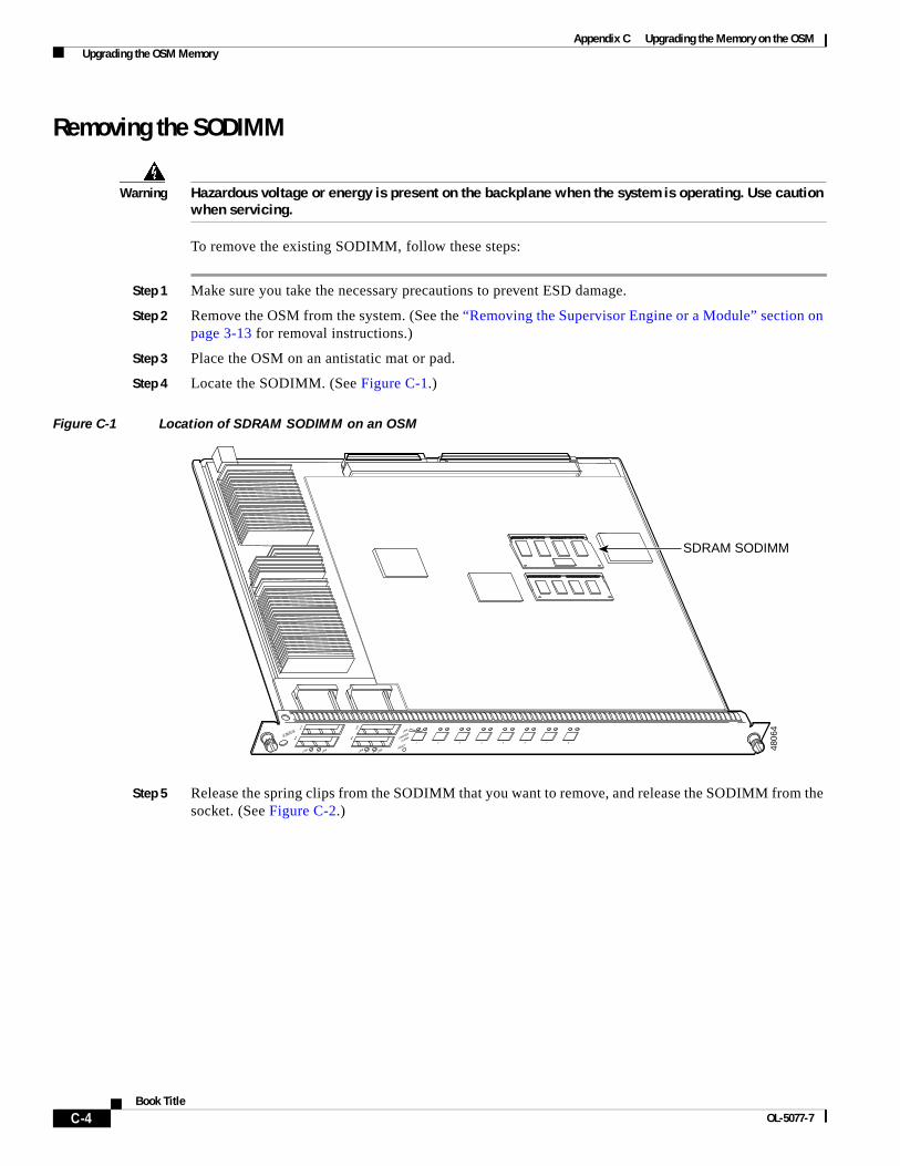
Appendix C Upgrading the Memory on the OSM Upgrading the OSM Memory
Removing the SODIMM
Warning Hazardous voltage or energy is present on the backplane when the system is operating. Use caution when servicing.
To remove the existing SODIMM, follow these steps:
Step 1 Make sure you take the necessary precautions to prevent ESD damage.
Step 2 Remove the OSM from the system. (See the “Removing the Supervisor Engine or a Module” section on page 3-13 for removal instructions.)
Step 3 Place the OSM on an antistatic mat or pad.
Step 4 Locate the SODIMM. (See Figure C-1.)
Figure C-1 Location of SDRAM SODIMM on an OSM
Step 5 Release the spring clips from the SODIMM that you want to remove, and release the SODIMM from the socket. (See Figure C-2.)
WS-X5530
STATUS
LINE LINE
1
1
1 2 3 4 5 6 7 8
2 LINE LINE
LINK
RESET
CARRIER
ALARM
3 4
2
3
4
SDRAM SODIMM
4806
4
C-4Book Title
OL-5077-7
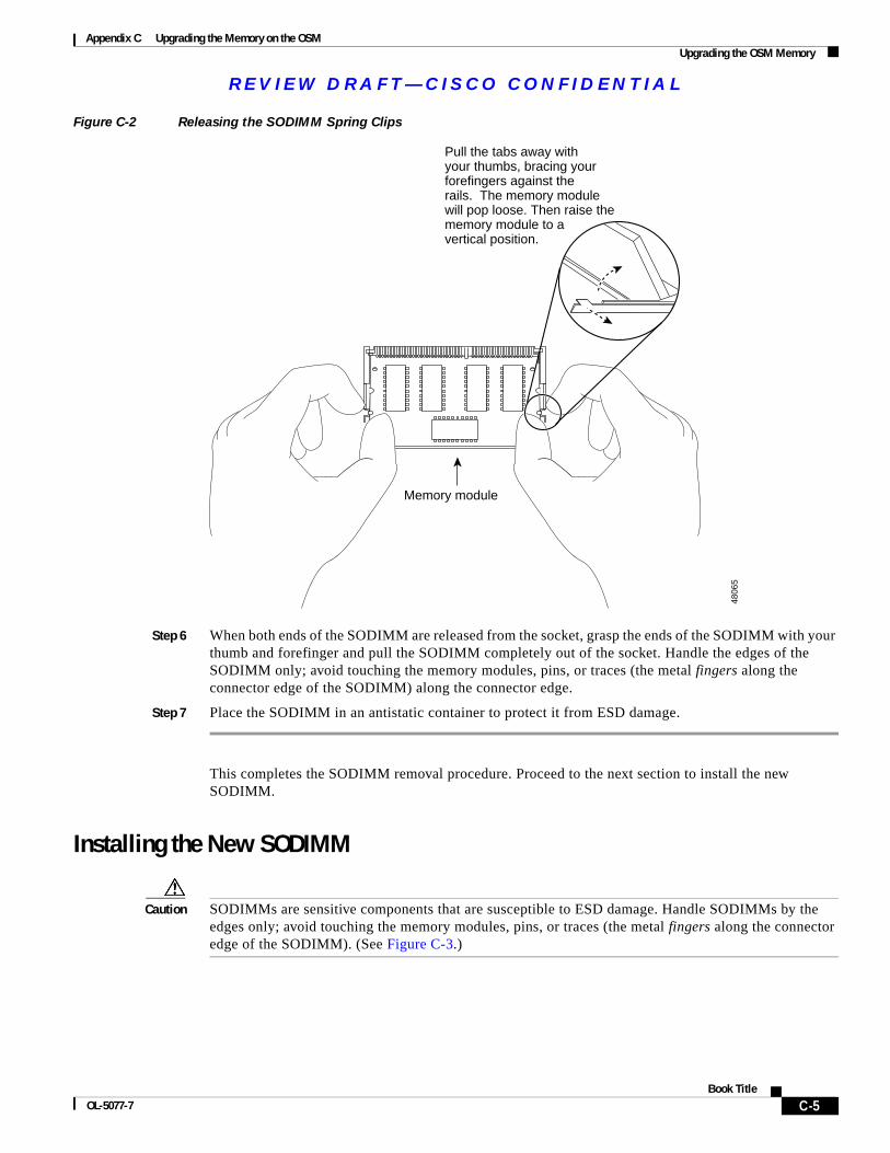
REVIEW DRAFT—CISCO CONF IDENT IAL
Appendix C Upgrading the Memory on the OSM Upgrading the OSM Memory
Figure C-2 Releasing the SODIMM Spring Clips
Step 6 When both ends of the SODIMM are released from the socket, grasp the ends of the SODIMM with your thumb and forefinger and pull the SODIMM completely out of the socket. Handle the edges of the SODIMM only; avoid touching the memory modules, pins, or traces (the metal fingers along the connector edge of the SODIMM) along the connector edge.
Step 7 Place the SODIMM in an antistatic container to protect it from ESD damage.
This completes the SODIMM removal procedure. Proceed to the next section to install the new SODIMM.
Installing the New SODIMM
Caution SODIMMs are sensitive components that are susceptible to ESD damage. Handle SODIMMs by the edges only; avoid touching the memory modules, pins, or traces (the metal fingers along the connector edge of the SODIMM). (See Figure C-3.)
Memory module
Pull the tabs away with your thumbs, bracing your forefingers against the rails. The memory module will pop loose. Then raise the memory module to a vertical position.
4806
5
C-5Book Title
OL-5077-7
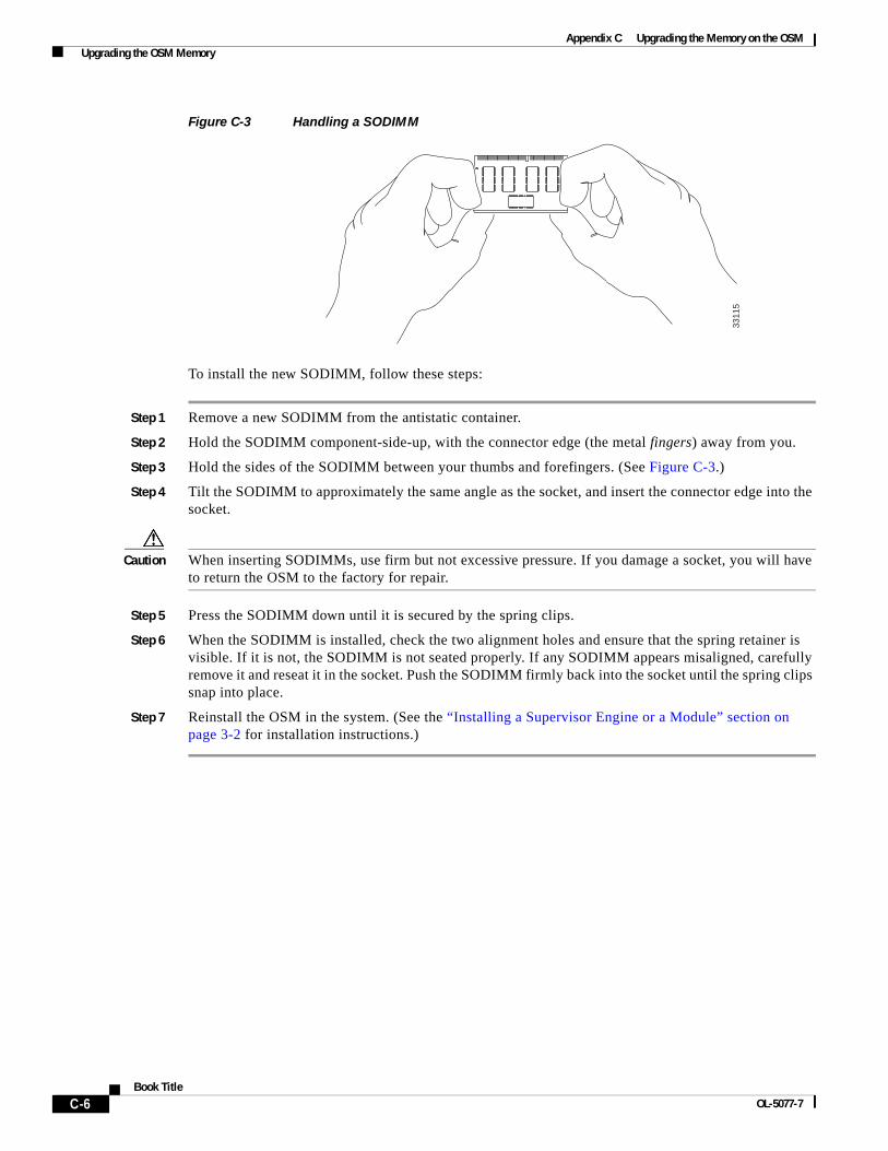
Appendix C Upgrading the Memory on the OSM Upgrading the OSM Memory
Figure C-3 Handling a SODIMM
To install the new SODIMM, follow these steps:
Step 1 Remove a new SODIMM from the antistatic container.
Step 2 Hold the SODIMM component-side-up, with the connector edge (the metal fingers) away from you.
Step 3 Hold the sides of the SODIMM between your thumbs and forefingers. (See Figure C-3.)
Step 4 Tilt the SODIMM to approximately the same angle as the socket, and insert the connector edge into the socket.
Caution When inserting SODIMMs, use firm but not excessive pressure. If you damage a socket, you will have to return the OSM to the factory for repair.
Step 5 Press the SODIMM down until it is secured by the spring clips.
Step 6 When the SODIMM is installed, check the two alignment holes and ensure that the spring retainer is visible. If it is not, the SODIMM is not seated properly. If any SODIMM appears misaligned, carefully remove it and reseat it in the socket. Push the SODIMM firmly back into the socket until the spring clips snap into place.
Step 7 Reinstall the OSM in the system. (See the “Installing a Supervisor Engine or a Module” section on page 3-2 for installation instructions.)
3311
5
C-6Book Title
OL-5077-7
OL-5077-7
I N D E X
Numerics
16-Port Gigabit Ethernet Switching Module (WS-X6516-GBIC), description 1-26
48-Port 10/100TX Switching Module (WS-X6348-RJ-45), description 1-26
7600-ES20-10G3C
description 1-32
7600-ES20-10G3CXL
description 1-32
7600-ES20-10G line card
LEDs 1-32
7600-ES20-GE3C
description 1-32
7600-ES20-GE3CXL
description 1-32
A
accessories box, console port 3-15, B-2
access server console port
control signal conflicts 4-23
access servers
unconfigured, unresponsive terminal connections 4-22, 4-23
ACTIVE LED, supervisor engine 1-12, 1-13, 1-14
addresses
MAC 1-38
physical interface 1-37
ports 1-37
ATM maximum transmission distances 2-12
audience 1-7
B
banners
system
Cisco 7500 series routers 4-3
blank module carriers 3-3
boot Flash 1-4
booting problems
local timeouts from ROM 4-22
routers 4-4
Cisco 7500 series 4-1, 4-2, 4-3
Flash memory 4-4, 4-5, 4-7, 4-8, 4-9, 4-11, 4-12, 4-14, 4-15, 4-17, 4-18, 4-19
hangs after ROM monitors initialize 4-20
stuck in ROM monitor mode 4-20, 4-21
scrambled output from ROM 4-21
unresponsive terminal connections, unconfigured access servers 4-22, 4-23
boot prompt
routers booting from Flash memory 4-17, 4-18, 4-19
boot system command
router boot failures, Flash memory 4-19
break keys, pressed during boot process 4-21
C
cables 2-10
console, boot problems 4-21
distance limitations
ATM 2-12
description 2-10
Ethernet 2-13
Fast Ethernet 2-11
Gigabit Ethernet 2-13
IN-1Book Title
Index
UTP
Category 3 2-11
Category 5 2-11
cable specifications B-1
cabling
console port 2-16, B-2
unconditioned laser source on SMF 2-14
Catalyst 6000 family modules, description 1-24
Category 3 UTP 2-11
Category 5 UTP 2-11
channelized OC-12, description 1-19
Cisco 7600 Internet Router
description 1-1
features 1-3
commands
boot system flash
router boot failures, Flash memory 4-19
conventions 1-8
show interfaces 1-38
show module 3-22
compressed system images
router boot failures, Flash memory 4-8, 4-15
configuration registers
misconfigurations 4-20, 4-21
configurations
configuration register
router boot failures, Flash memory 4-19
configuration registers 4-20, 4-21
connecting
modem 3-16
terminal 3-15
connections
terminals
unresponsive, unconfigured access servers 4-22, 4-23
connectors
LC, channelized OC-12 and OC-48 OSM 2-17
MT-RJ, OC-3 POS module 2-17
port connector requirements 2-16
IN-2Book Title
RJ-45
10/100BASE-TX 2-17
output signals B-2
SC 2-17, 3-17
console cables
boot problems 4-21
console port
accessories box 3-15
cable transmission distances 2-16
connecting to 3-15
description 1-15
port mode switch B-3
signaling and pinouts
mode 1 B-3
mode 2 B-5
control signals
conflicts, flow control 4-23
conventions 1-8
cooling subsystem problems
Cisco 7500 routers 4-2
corrupted images
router boot failures, Flash memory 4-5, 4-6, 4-7, 4-9, 4-10, 4-11, 4-12, 4-13, 4-14
D
DB-25 adapters B-4
DB-9 adapters B-3
differential mode delay
See DMD
distance limitations
ATM 2-12
cables 2-10
compared to laser transmission, figure 2-15
connections 2-10
description 2-10
Ethernet cables 2-13
Fast Ethernet cables 2-11
Gigabit Ethernet cables 2-13
OL-5077-7
Index
DMD 2-14
DRAM
default 1-4
upgrading C-1
E
EEPROM 1-4, 1-38
EIA/TIA-232 transmission speeds 2-16
electrostatic discharge
see ESD
environmental monitoring 1-39
EPROM
incorrect size settings 4-20
timeouts 4-22
errors
vector
booting routers from Flash memory 4-4, 4-8, 4-15
ESD, preventing damage 3-2
Ethernet and Fast Ethernet maximum transmission distances 2-11
examples, conventions 1-8
excessive link spans 2-16
exec functions
incorrect and corrupted images 4-7, 4-14
F
failures
routers
hangs after ROM monitor initializes 4-20
stuck in ROM monitor mode 4-20, 4-21
routers booting from Flash memory 4-4, 4-5, 4-7, 4-8, 4-9, 4-11, 4-12, 4-14, 4-15, 4-17, 4-18, 4-19
fault tolerance and redundancy 1-3
fiber-optic cable
ATM 2-12
channel capacity 2-10
Ethernet 2-11
OL-5077-7
Fast Ethernet 2-11
Gigabit Ethernet 2-13
filler plate, module 3-3
Flash memory
booting routers from 4-4, 4-5, 4-7, 4-8, 4-9, 4-11, 4-12, 4-14, 4-15, 4-17, 4-18, 4-19
Flash PC cards
sizes 3-21
using 3-20
write-protection switch 3-21
FlexWAN module
description 1-24, 1-25
figure 1-25, 1-26
speeds 1-24
STATUS LED 1-25
flow control
terminal configurations 4-23
functions
exec
incorrect and corrupted images 4-7, 4-14
G
GBICs 2-13
care and handling 3-17
connecting to 3-16
installing 3-18
LX/LH 1-26
removing 3-20
SX 1-26
ZX 1-26
Gigabit Ethernet
DMD occurrences 2-15
maximum transmission distances 2-13
H
hangs
routers, after ROM monitors initialize 4-20
IN-3Book Title
Index
hardware problems
booting routers 4-4
Cisco 7500 series routers 4-1, 4-2, 4-3
local timeouts, booting from ROM 4-22
routers
booting from Flash memory 4-4, 4-5, 4-7, 4-8, 4-9, 4-11, 4-12, 4-14, 4-15, 4-17, 4-18, 4-19
hangs after ROM monitors initialize 4-20
stuck in ROM monitor mode 4-20, 4-21
scrambled output, booting from ROM 4-21
unresponsive terminal connections, unconfigured access servers 4-22, 4-23
hot swapping
Cisco 7600 Internet Router components 1-4
supervisor engine and modules 1-39
I
IEEE, recommended signaling requirements 2-10
IEEE 802.3z 2-15
images
compressed system
router boot failures, Flash memory 4-8, 4-15
incorrect and corrupted
router boot failures, Flash memory 4-5, 4-6, 4-7, 4-9, 4-10, 4-11, 4-12, 4-13, 4-14
system
none in Flash memory 4-18
incorrect configuration register settings 4-20, 4-21
incorrect images
router boot failures, Flash memory 4-5, 4-6, 4-7, 4-9, 4-10, 4-11, 4-12, 4-13, 4-14
incorrect size settings, EPROM 4-20
initialization
ROM monitors, routers hang after 4-20
installing
modules 3-2
patch cord 2-14
supervisor engine 3-2
IN-4Book Title
K
keys
break, pressed during boot process 4-21
L
lasers 2-15
laser transmission 2-15
LC fiber-optic connector, channelized OC-12 and OC-48 OSM 2-17
LEDs 1-32, 1-34
OSMs
Active LED 1-23
Carrier Alarm LED 1-23
LINK LED 1-22
RX LED 1-23
TX LED 1-23
PWR MGMT 1-12, 1-13, 1-14, 1-15
recommended Catalyst 6000 family modules 1-29
supervisor engine
ACTIVE 1-12
ACTIVE LED 1-12, 1-13, 1-14
LINK LED 1-12, 1-13, 1-14, 1-15
PCMCIA LED 1-12
SYSTEM LED 1-12, 1-13, 1-14
transmission 2-15
LED transmission 2-15
light pathways
See modes
LINK LED
OSM 1-22
supervisor engine 1-12, 1-13, 1-14, 1-15
link spans, excessive 2-16
local timeouts, booting from ROM 4-22
LX/LH GBIC 1-26, 2-13, 2-17
OL-5077-7
Index
M
MAC address
allocation 1-38
description 1-37
management 1-4
memory
default, OSM 1-4
Flash
booting routers from 4-4, 4-5, 4-7, 4-8, 4-9, 4-11, 4-12, 4-14, 4-15, 4-17, 4-18, 4-19
upgrading, OSM C-1
memory components 1-4
misconfigurations
configuration register
router boot failures, Flash memory 4-19
configuration registers 4-20, 4-21
missing commands
boot system flash
router boot failures, Flash memory 4-19
modem, connecting to 3-16
modem adapter B-4
modes
ROM monitor
routers stuck in 4-20, 4-21
modes, fiber 2-14
module functionality
hot swapping 1-39
MAC address 1-37
MAC address allocation 1-38
physical interface addresses 1-37
port addresses 1-37
modules
blank module carriers 3-3
installing 3-7
monitors
ROM
routers hang after initialization 4-20
MT-RJ connector, OC-3 POS module 2-17
OL-5077-7
multimode fiber-optic cable
Ethernet and Fast Ethernet 2-11
Gigabit Ethernet 2-13
N
NVRAM 1-4
O
OC-12 ATM, description 1-20
OC-12 POS, description 1-18
OC-3 POS, description 1-17
OC-48 POS, description 1-18
Optical Services Modules
See OSMs
organization 1-7
OSMs
channelized OC-12 1-19
LEDs
Active LED 1-23
Carrier Alarm LED 1-23, 1-24
LINK LED 1-22, 1-24
RX LED 1-23
STATUS LED 1-21
TX LED 1-23
OC-12 ATM 1-20
OC-12c POS 1-18
OC-3c POS 1-17
OC-48 POS 1-18
output
scrambled, booting from ROM 4-21
output signals, RJ-45 Fast Ethernet connector B-2
overfilled launch condition 2-15
P
patch cord
IN-5Book Title
Index
configuration example 2-14
differential mode delay 2-14
installation 2-14
using with LX/LH GBICs 2-13
PCMCIA
See also Flash PC card
PCMCIA Flash
Flash file system 1-4
using Flash PC cards 3-20
PCMCIA LED 1-12
PCMCIA slot, description 1-16
physical interface addresses 1-37
port addresses 1-37
port mode switch
description 1-15
mode 1 B-3
mode 2 B-5
use of 3-15, B-2
ports
access server console, control signal conflicts 4-23
power management 1-39
power subsystem problems
Cisco 7500 routers 4-2
preventing ESD damage 3-2
processor subsystem problems
Cisco 7500 routers 4-3
prompts
boot
routers booting from Flash memory 4-17, 4-18, 4-19
PWR MGMT LED 1-12, 1-13, 1-14, 1-15
R
recommended Catalyst 6000 family modules
description 1-24
LED description 1-29
STATUS LED 1-29
WS-C6500-SFM 1-27
IN-6Book Title
WS-X6182-2PA 1-24
WS-X6348-RJ-45 1-26
WS-X6516-GBIC 1-26
redundancy 1-3
registers
configuration
misconfigurations 4-20, 4-21
router boot failures, Flash memory 4-19
related documentation 1-13
removing
modules 3-13
supervisor engine 3-13
required tools
module installation 3-1
upgrading OSM memory C-3
Reset button, description 1-15
RJ-45 connector, 10/100BASE-TX 2-17
rollover cable B-3
ROM
local timeouts when booting from 4-22
scrambled output when booting from 4-21
ROM monitor mode
routers stuck in 4-20, 4-21
ROM monitors
routers hang after initialization 4-20
routers
booting problems 4-4
Cisco 7500 series 4-1, 4-2, 4-3
S
safety C-1
SC connector
GBIC interfaces 2-17
OSM interfaces 2-17
scrambled output, booting from ROM 4-21
servers
access
OL-5077-7
Index
unconfigured, unresponsive terminal connections 4-22, 4-23
settings
configuration registers 4-20, 4-21
size, EPROM 4-20
terminal speed 4-22
show interfaces command 1-38
show module command 3-22
signaling requirements, IEEE-recommended 2-10
signals
control
conflicts, flow control 4-23
single mode fiber-optic cable 2-13
size settings, EPROM 4-20
slot numbering 3-4, 3-5, 3-6, 3-7
speed
terminal settings 4-22
standards compliance A-2
STATUS LED
Catalyst 6000 family modules 1-29
OSMs 1-21
supervisor engine 1-12, 1-13, 1-14
supervisor engine
console port 1-15
console port mode switch 1-15
front panel features
console port 1-15
LEDs 1-11
PCMCIA slot 1-16
port mode switch 1-15
Reset button 1-15
switch load meter 1-16
uplink ports 1-16
LEDs
ACTIVE LED 1-12, 1-13, 1-14
LINK LED 1-12, 1-13, 1-14, 1-15
PCMCIA LED 1-12
PWR MGMT LED 1-12, 1-13, 1-14, 1-15
STATUS LED 1-12, 1-13, 1-14
OL-5077-7
SWITCH LOAD meter 1-12
SYSTEM LED 1-12, 1-13, 1-14
PCMCIA slot 1-16
Reset button 1-15
Supervisor Engine 720
chassis slot assignments 3-2
supervisor engine slot assignements (table) 3-3
Switch Fabric Module
ACTIVE LED 1-27, 1-28
description 1-27
figure 1-27, 1-28
LCD display 1-27, 1-28
STATUS LED 1-27, 1-28
switch load meter, description 1-16
SWITCH LOAD meter, supervisor engine 1-12
SX GBIC 1-26
system banner
Cisco 7500 series routers 4-3
system images
none in Flash memory 4-18
SYSTEM LED, supervisor engine 1-12, 1-13, 1-14
T
terminal, connecting to 3-15
terminals
flow control configurations 4-23
unresponsive connections, unconfigured access servers 4-22, 4-23
terminal speed settings 4-22
timeouts
local, booting from ROM 4-22
tools, required
for module installation 3-1
for upgrading OSM memory C-3
IN-7Book Title
Index
U
unconfigured access servers, unresponsive terminal connections 4-22, 4-23
unresponsive terminal connections, unconfigured access servers 4-22, 4-23
upgrading memory
required tools C-3
safety C-1
uplink ports
connecting to 3-16
description 1-16
UTP
Category 3 2-11
Category 5 2-11
maximum transmission distances, Ethernet and Fast Ethernet 2-11
V
vector errors
booting routers from Flash memory 4-4, 4-8, 4-15
verification, installation of modules 3-22
W
write command 3-13
write-protection switch on Flash PC card 3-21
WS-C6500-SFM 1-27
WS-X6182-2PA 1-24
WS-X6348-RJ-45 1-26
WS-X6516-GBIC 1-26
Z
ZX GBIC 1-26
IN-8Book Title
OL-5077-7