Embed Size (px)
Citation preview
Configuration Note
© Copyright 2007 Avaya Inc. All rights reserved PN: Cisco 44xx WLC with AP 1100_1200 Configuration Note for 3631 phone.doc Page 1
Cisco 4400 Series Wireless LAN Controller (WLC) with Aironet 1100/1200 Series APs for Avaya 3631 Wireless Telephone Configuration and Deployment Guide
This document details how to configure the Cisco 4400 series WLC and Aironet 1100/1200 Series APs for use with Avaya 3631 wireless IP telephones.
Product Summary Manufacturer: Cisco Systems: www.cisco.com Products 4400 series WLC with AP 1131 and LWAPP-
capable 1200 series APs RF technology: Spread spectrum direct sequence (DS)
Radio: 2.4 – 2.484 GHz
Antenna diversity: Bi-directional Security : WEP, WPA-PSK and WPA2-PSK
Maximum telephone calls per AP: 10
Recommended network topology: Switched Ethernet (required)
Service Information
This document does not cover the steps involved in converting autonomous APs to LWAPP APs such that they can be controlled by the 4400 WLC. Please contact Cisco's Customer Support at www.cisco.com for instructions on this procedure. Once the APs are converted, this document can be used to provision LWAPP APs.
Configuration Note
PN: Cisco 44xx WLC with AP 1100_1200 Configuration Note for 3631 phone.doc Page 2
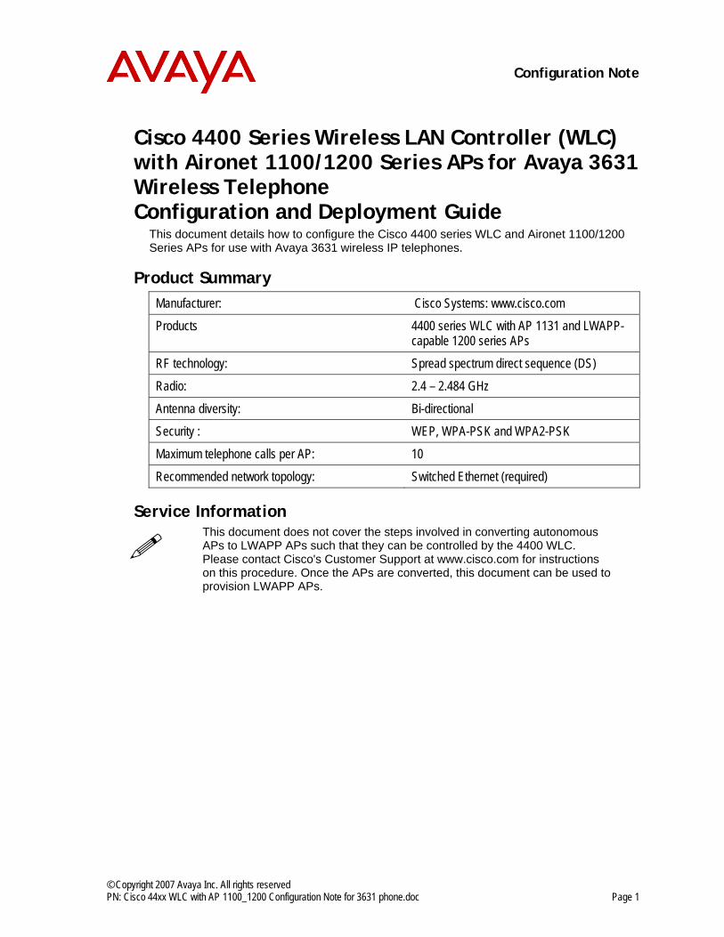
Network Topology The following topology is an example configuration using a Cisco WLC and Cisco LWAP APs across different subnets. It is important to note that these do not necessarily represent all possible configurations.
OK
Switch Switch
DHCP-, HTTP-, FTP-Server
Switch
Avaya CM
Router
Avaya 3631
Cisco 4400 Series WLAN Controller
Aironet AG1240 series
Aironet AG1240 series
Aironet AG1240 series
Aironet AG1240 series
OK
Avaya 3631
OK
Avaya 3631
OK
Avaya 3631
OK
Avaya 3631
OK
Avaya 3631
Tunnel
Example configuration showing WLAN infrastructure distributed in two different subnets using layer 3 roaming. Please note that all WLAN traffic is tunneled via the Cisco 4400 Series WLAN controller. All phones have IP addresses of the subnet holding the WLAN controller, independent from the AP they are currently connected to.
Known Limitations No limitations were discovered during testing.
Configuration Note
PN: Cisco 44xx WLC with AP 1100_1200 Configuration Note for 3631 phone.doc Page 3
Cisco WLAN Controller (WLC) Configuration
Configuring a New Controller Starting From Factory Defaults Connecting to WLC via the Console 1. Initial provisioning of the controller is done via the command line interface (CLI). Connect
a null modem serial cable between the console port of the controller and the serial port of a PC.
2. Open a terminal program, such as Hyper Terminal, and configure the port settings to 9600 baud, no parity, 8 data bits and 1 stop bit.
Basic Configuration 1. Power-on the controller. Status of the controller’s boot process will appear as the
controller is powering up. Once the controller is running, it will prompt you to run the Startup Wizard.
2. The Startup Wizard provides for an easy means to perform initial controller setup and provisioning. Refer to the Installation and Startup Guide for the 4400 series controllers found at Cisco’s web site. This document contains a detailed explanation of using the Startup Wizard: http://www.cisco.com/en/US/products/ps6366/products_quick_start_chapter09186a008056add1.html
3. Once the controller has been configured via the Startup Wizard, the remaining configuration can be configured through the switch-web interface using a webbrowser (Cisco recommends using MS IE 6.0+).
4. If necessary, the controller can be reset to factory defaults. To reset the WLC to factory default, you must reboot, then type “Recover-config” at the CLI. This only works before the first time a user logs in via the console.
Configuration Note
PN: Cisco 44xx WLC with AP 1100_1200 Configuration Note for 3631 phone.doc Page 4
Configuring the Cisco WLAN Controller for use with Avaya 3631 phones
Further configurations of the Cisco WLC can be done both using a Web Browser interface or a Command Line interface. Avaya recommends using the Web Browser interface as described in the following sections.
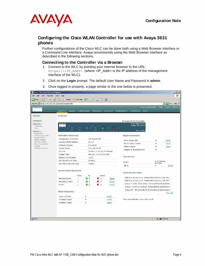
Connecting to the Controller via a Browser 1. Connect to the WLC by pointing your internet browser to the URL:
https://<IP_Addr> (where <IP_Addr> is the IP address of the management interface of the WLC).
2. Click on the Login prompt. The default User Name and Password is admin.
3. Once logged in properly, a page similar to the one below is presented:
Configuration Note
PN: Cisco 44xx WLC with AP 1100_1200 Configuration Note for 3631 phone.doc Page 5
Installing Software 1. Make sure that the latest version of software is installed on the controller. From the main
menu, select Monitor> Summary. The heading labeled Software Version shows the current software version.
2. Download the appropriate software for your model of controller from the Cisco Wireless LAN Controller Software Downloads website.
3. Set up a TFTP server running on a PC to download the file to the controller. 4. Connect to the controller via a Web browser, preferably IE. Select Commands from the
main menu, and then select Download File. 5. For File Type, select Code. For TFTP Server, type in the IP Address of the TFTP
Server, Add the Path (this is the path in the TFTP server's root directory and not the system path where the TFTP server is located) and File Name of the firmware file to download.
6. Allow a few minutes for the download to complete.
Configuration Note
PN: Cisco 44xx WLC with AP 1100_1200 Configuration Note for 3631 phone.doc Page 6
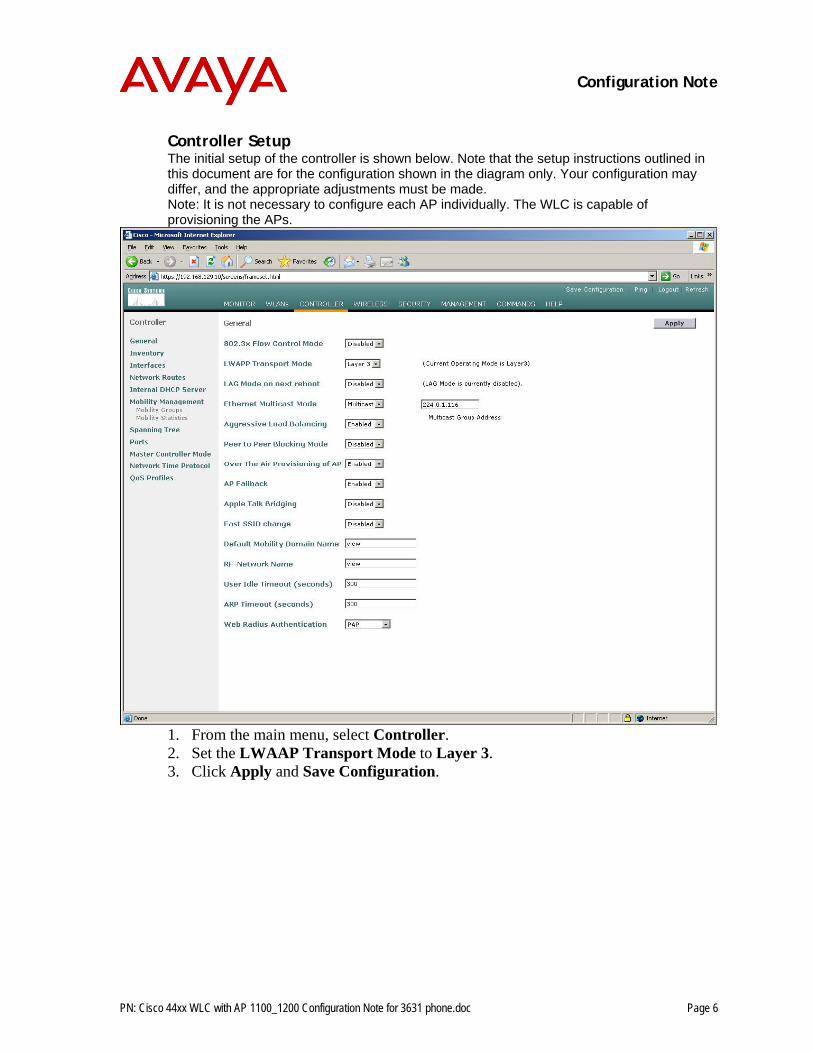
Controller Setup The initial setup of the controller is shown below. Note that the setup instructions outlined in this document are for the configuration shown in the diagram only. Your configuration may differ, and the appropriate adjustments must be made. Note: It is not necessary to configure each AP individually. The WLC is capable of provisioning the APs.
1. From the main menu, select Controller. 2. Set the LWAAP Transport Mode to Layer 3. 3. Click Apply and Save Configuration.
Configuration Note
PN: Cisco 44xx WLC with AP 1100_1200 Configuration Note for 3631 phone.doc Page 7
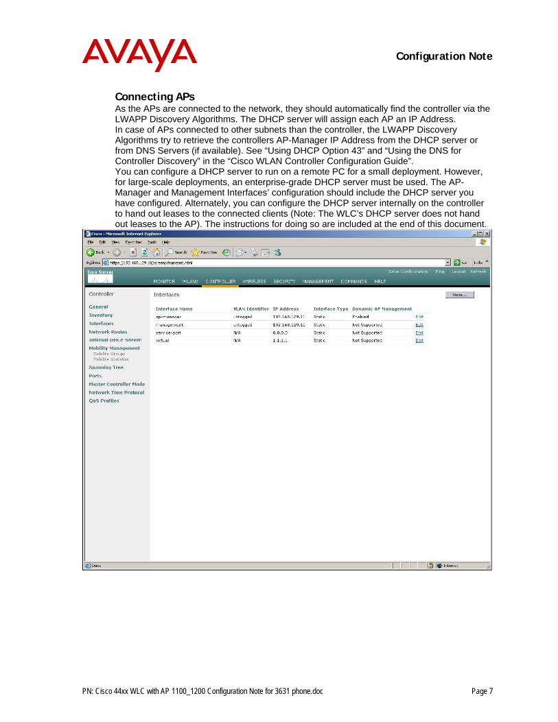
Connecting APs As the APs are connected to the network, they should automatically find the controller via the LWAPP Discovery Algorithms. The DHCP server will assign each AP an IP Address. In case of APs connected to other subnets than the controller, the LWAPP Discovery Algorithms try to retrieve the controllers AP-Manager IP Address from the DHCP server or from DNS Servers (if available). See “Using DHCP Option 43” and “Using the DNS for Controller Discovery” in the “Cisco WLAN Controller Configuration Guide”. You can configure a DHCP server to run on a remote PC for a small deployment. However, for large-scale deployments, an enterprise-grade DHCP server must be used. The AP-Manager and Management Interfaces’ configuration should include the DHCP server you have configured. Alternately, you can configure the DHCP server internally on the controller to hand out leases to the connected clients (Note: The WLC’s DHCP server does not hand out leases to the AP). The instructions for doing so are included at the end of this document.
Configuration Note
PN: Cisco 44xx WLC with AP 1100_1200 Configuration Note for 3631 phone.doc Page 8
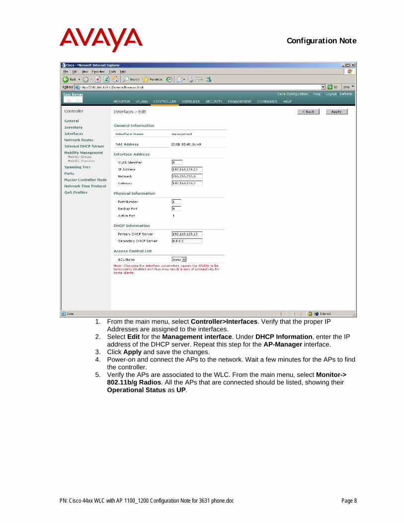
1. From the main menu, select Controller>Interfaces. Verify that the proper IP
Addresses are assigned to the interfaces. 2. Select Edit for the Management interface. Under DHCP Information, enter the IP
address of the DHCP server. Repeat this step for the AP-Manager interface. 3. Click Apply and save the changes. 4. Power-on and connect the APs to the network. Wait a few minutes for the APs to find
the controller. 5. Verify the APs are associated to the WLC. From the main menu, select Monitor->
802.11b/g Radios. All the APs that are connected should be listed, showing their Operational Status as UP.
Configuration Note
PN: Cisco 44xx WLC with AP 1100_1200 Configuration Note for 3631 phone.doc Page 9
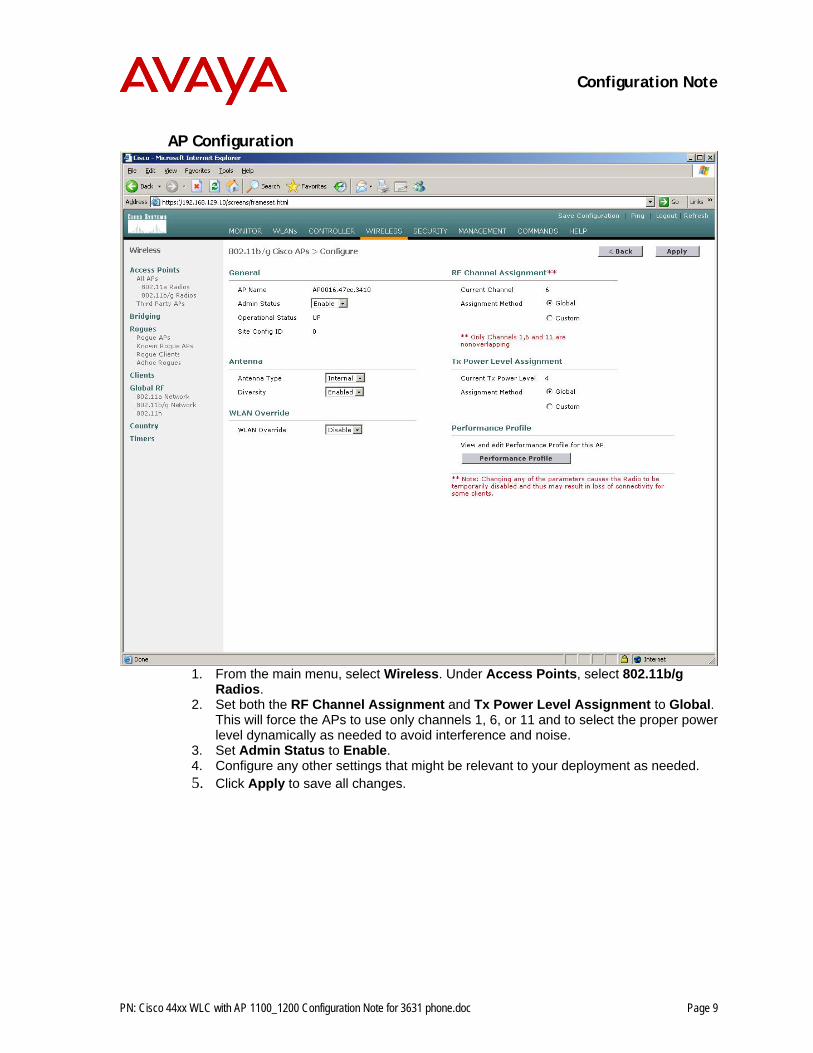
AP Configuration
1. From the main menu, select Wireless. Under Access Points, select 802.11b/g
Radios. 2. Set both the RF Channel Assignment and Tx Power Level Assignment to Global.
This will force the APs to use only channels 1, 6, or 11 and to select the proper power level dynamically as needed to avoid interference and noise.
3. Set Admin Status to Enable. 4. Configure any other settings that might be relevant to your deployment as needed. 5. Click Apply to save all changes.
Configuration Note
PN: Cisco 44xx WLC with AP 1100_1200 Configuration Note for 3631 phone.doc Page 10
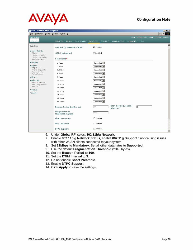
6. Under Global RF, select 802.11b/g Network. 7. Enable 802.11b/g Network Status, enable 802.11g Support if not causing issues
with other WLAN clients connected to your system. 8. Set 11Mbps to Mandatory. Set all other data rates to Supported. 9. Use the default Fragmentation Threshold (2346 bytes). 10. Set the Beacon Period to 100. 11. Set the DTIM Interval to 3. 12. Do not enable Short Preamble. 13. Enable DTPC Support. 14. Click Apply to save the settings.
Configuration Note
PN: Cisco 44xx WLC with AP 1100_1200 Configuration Note for 3631 phone.doc Page 11
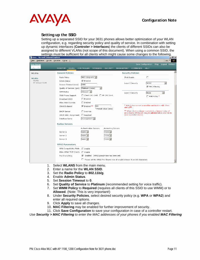
Setting up the SSID Setting up a separated SSID for your 3631 phones allows better optimization of your WLAN configuration, e.g. regarding security policy and quality of service. In combination with setting up dynamic interfaces (Controler > Interfaces) the clients of different SSIDs can also be assigned to different VLANs (not scope of this document). When using a common SSID, the settings must be sufficient for all clients which might cause some changes to the following.
1. Select WLANS from the main menu. 2. Enter a name for the WLAN SSID. 3. Set the Radio Policy to 802.11b/g. 4. Enable Admin Status. 5. Set Session Timeout to 0. 6. Set Quality of Service to Platinum (recommended setting for voice traffic). 7. Set WMM Policy to Required (requires all clients of this SSID to use WMM) or to
Allowed. (Note: This is very important!) 8. Under Security Policies, select desired security policy (e.g. WPA or WPA2) and
enter all required options. 9. Click Apply to save all changes. 10. MAC Filtering may be enabled for further improvement of security. 11. Click Save Configuration to save your configuration in case of a controller restart.
Use Security > MAC Filtering to enter the MAC addresses of your phones if you enabled MAC Filtering
Configuration Note
PN: Cisco 44xx WLC with AP 1100_1200 Configuration Note for 3631 phone.doc Page 12
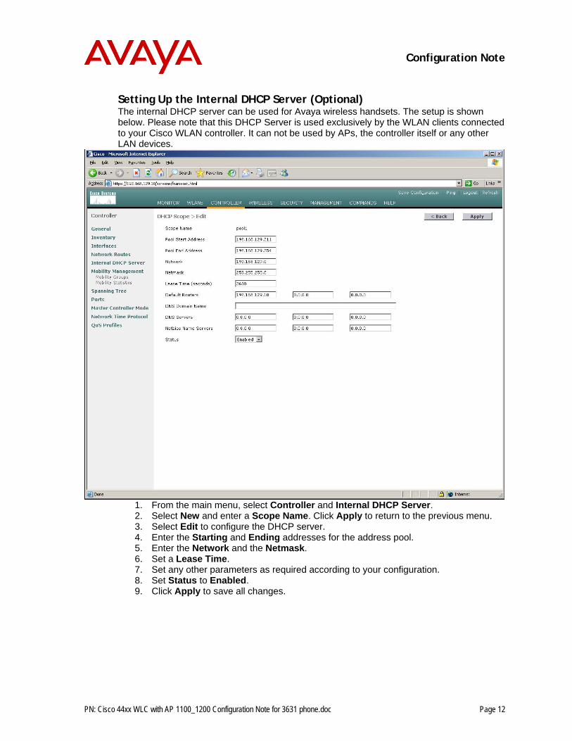
Setting Up the Internal DHCP Server (Optional) The internal DHCP server can be used for Avaya wireless handsets. The setup is shown below. Please note that this DHCP Server is used exclusively by the WLAN clients connected to your Cisco WLAN controller. It can not be used by APs, the controller itself or any other LAN devices.
1. From the main menu, select Controller and Internal DHCP Server. 2. Select New and enter a Scope Name. Click Apply to return to the previous menu. 3. Select Edit to configure the DHCP server. 4. Enter the Starting and Ending addresses for the address pool. 5. Enter the Network and the Netmask. 6. Set a Lease Time. 7. Set any other parameters as required according to your configuration. 8. Set Status to Enabled. 9. Click Apply to save all changes.
Configuration Note
PN: Cisco 44xx WLC with AP 1100_1200 Configuration Note for 3631 phone.doc Page 13
Further Assistance 1. A configuration guide for the 4400 WLC can be found on Cisco’s website:
http://www.cisco.com/en/US/products/ps6366/products_configuration_guide_book09186a00806b0077.html
2. To convert the 1200 Series autonomous AP to an LWAPP, go to: http://www.cisco.com/en/US/products/hw/wireless/ps430/prod_technical_reference09186a00804fc3dc.html
3. For more information on the LWAPP-Enabled APs, see Quick Start Guide LWAPP-Enabled Cisco Aironet Access Points at: http://www.cisco.com/en/US/products/hw/wireless/ps430/products_quick_start09186a00805100f5.html
4. For other assistance, contact Avaya's customer service at: http://support.avaya.com