Embed Size (px)
Citation preview
CHRONO: A PARALLEL PHYSICS LIBRARY FOR RIGID-BODY, FLEXIBLE-BODY,AND FLUID DYNAMICS
Toby HeynHammad MazharArman PazoukiDaniel MelanzAndrew Seidl
Justin MadsenAaron Bartholomew
Dan NegrutSimulation Based Engineering Lab
Department of Mechanical EngineeringUniversity of Wisconsin
Madison, WI, 53706Email: [email protected]
David LambUS Army TARDECWarren, MI 48397
Email: [email protected]
Alessandro TasoraDepartment of Industrial Engineering
University of ParmaV.G.Usberti 181/A, 43100, Parma, Italy
Email: [email protected]
ABSTRACT
This contribution discusses a multi-physics simulation engine,called Chrono, that relies heavily on parallel computing.Chrono aims at simulating the dynamics of systems containingrigid bodies, flexible (compliant) bodies, and fluid-rigid body in-teraction. To this end, it relies on five modules: equation for-mulation (modeling), equation solution (simulation), collisiondetection support, domain decomposition for parallel comput-ing, and post-processing analysis with emphasis on high qual-ity rendering/visualization. For each component we point outhow parallel CPU and/or GPU computing have been leveragedto allow for the simulation of applications with millions of de-grees of freedom such as rover dynamics on granular terrain,fluid-structure interaction problems, or large-scale flexible bodydynamics with friction and contact for applications in polymeranalysis.
Introduction
About 50% of all traded products worldwide are in granularform. Grain, rice, sugar, coffee, cereal, salt, sand, drug pills
and the constituents of a pill, animal feed pellets, and fertiliz-ers are examples of granular material. Granular material andits storing/packing/motion come up in the design of a combine,the mobility of a Mars rover, avalanche dynamics, earthquakes,and the formation of asteroids and planets. Although granularproblems are so pervasive, characterizing the dynamics of thismedium in real-life applications remains an open problem. Theproblem of handling granular material becomes even more chal-lenging when they form a suspension carried out in a flowingliquid. This contribution summarizes an effort aimed at address-ing these and other questions such as: how is the shape/geometryof the bodies flowing in a liquid determine their time evolution?What happens when these floating bodies are long and flexible,which is effectively the case in polymer simulation?
To the best of our knowledge, there is no commercial or opensource solution capable of characterizing through simulation thetime evolution of such systems. These problems are governedby very large sets of ordinary differential equations and/or dif-ferential algebraic equations and/or partial differential equations.There are many open questions in the modeling stage; i.e., in thevery process of formulating these equations. Moreover, there arenumerous difficult questions in relation to their numerical solu-
1 Copyright © 2013 by ASME
Proceedings of the ASME 2013 International Design Engineering Technical Conferences and Computers and Information in Engineering Conference
IDETC/CIE 2013 August 4-7, 2013, Portland, Oregon, USA
DETC2013-13239
This work is in part a work of the U.S. Government. ASME disclaims all interest in the U.S. Government’s contributions.
tion. Attempts to answer these questions by this team have beensummarized elsewhere [1, 2, 3]. In this contribution the empha-sis is placed on discussing how parallel computing has allowedus to increase the size of the problems tackled by direct numeri-cal simulation to levels that one decade ago would have seemedintractable. The paper is organized as follows: Chrono::Rigidpresents implementation details related to the rigid body dynam-ics simulation engine; this is the most mature component ofChrono and and draws on both GPU and CPU parallel comput-ing. Section Chrono::Flex gives a high level perspective on theChrono component that formulates and solve the equations ofmotion associated with large collections of flexible bodies thatcan potentially interact through friction and contact. SectionChrono::Fluid outlines the framework that supports the sim-ulation of fluid-solid interaction problems. Since some of theproblems analyzed have millions of components, rendering highquality animations to present the time evolutions of these sys-tems can be prohibitively long. Section Chrono::Render dis-cusses a rendering pipeline that can leverage up to 320 instancesof a commercial renderer to generate in parallel feature-rich im-ages. Conclusions, directions of future work, and informationabout the availability of Chrono round up the paper.
Chrono::Rigid
Chrono::Rigid is a general-purpose simulation environment forthree-dimensional problems with many rigid bodies [3]. Thisenvironment supports the simulation of very large systems com-mon to those encountered in granular dynamics, where millionsof objects can be interacting at any given time. Applicationswhere this tool could be used include the simulation of trackedvehicles on granular terrain [4] or a rover operating on granularsoil made up of discrete particles. In these applications granularterrain is modeled as a collection of millions of discrete bodieswhich interact through contact, friction and impact. Additionallythese systems contain complex mechanisms composed of jointsand rigid bodies. Chrono::Rigid was initially developed usingthe Differential Variational Inequality (DVI) formulation as anefficient way to deal with problems that contain many objectsinteracting through friction and contact - a typical bottleneck forother types of formulations [5,6]. Chrono::Rigid has since beenextended to support the Discrete Element Method (DEM) formu-lation for solving granular dynamics problems with friction andcontact [7, 8].
Using MPI for distributed Chrono::Rigid
This is an extension of the Chrono environment to leverage mul-ticore compute clusters through the Message Passing Interface(MPI) [9]. Specifically, a domain decomposition approach has
FIGURE 1: Snapshot of Mars Rover simulation with 2,016,000 terrain par-ticles using 64 sub-domains. Bodies are colored by sub-domain, with sharedbodies (those which span sub-domain boundaries) colored white.
been implemented in which the simulation domain is divided intoa number of sub-domains, each of which is mapped to a computecore for execution. Communication and synchronization occurat each time step of the simulation, as bodies may move be-tween sub-domains. This framework currently uses the DiscreteElement Method (DEM) formulation in which small interpene-trations between colliding rigid bodies are penalized based on aforce model (see for example, [8]).
To demonstrate the capabilities of this framework, a Mars Rovertype vehicle has been simulated operating on discrete granularterrain. The vehicle is modeled with a chassis and six wheelsdriven with a constant angular velocity of π rad/sec. The gran-ular terrain is represented by 2,016,000 spherical particles. Thesystem is divided into 64 sub-domains and simulated on a singlenode with 4 x AMD Opteron 6274 2.2GHz 16 core processors.A snapshot of the simulation can be seen in Fig. 1.
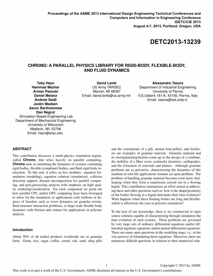
CPU vs GPU Comparison For the CPU vs GPU compari-son, simulations with increasing number of bodies were run. Ineach scenario, granular material was dropped into a box enclosedon all sides by rigidly fixed walls. Three seconds of this simu-lation were simulated, the total time taken for each simulationis presented in Fig. 2. The number of bodies simulated rangedfrom about 2300 for the smallest case to 16000 for the largest.It should be noted that for simulations smaller than 2000 bod-ies, the overhead associated with transferring data between theGPU and CPU is very large compared to the computational time.Also when solving such a small problem on the GPU, the largenumber of processing cores (480 in the case of the GTX 480)means that many cores will be idle and the full compute powerof the GPU will not be utilized. Therefore for small problems it
2 Copyright © 2013 by ASME
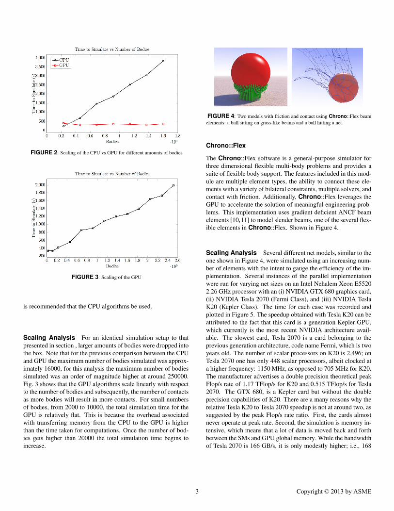
FIGURE 2: Scaling of the CPU vs GPU for different amounts of bodies
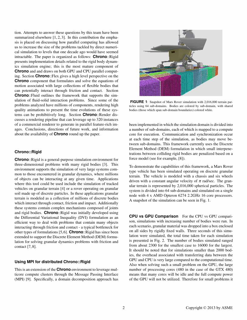
FIGURE 3: Scaling of the GPU
is recommended that the CPU algorithms be used.
Scaling Analysis For an identical simulation setup to thatpresented in section , larger amounts of bodies were dropped intothe box. Note that for the previous comparison between the CPUand GPU the maximum number of bodies simulated was approx-imately 16000, for this analysis the maximum number of bodiessimulated was an order of magnitude higher at around 250000.Fig. 3 shows that the GPU algorithms scale linearly with respectto the number of bodies and subsequently, the number of contactsas more bodies will result in more contacts. For small numbersof bodies, from 2000 to 10000, the total simulation time for theGPU is relatively flat. This is because the overhead associatedwith transferring memory from the CPU to the GPU is higherthan the time taken for computations. Once the number of bod-ies gets higher than 20000 the total simulation time begins toincrease.
FIGURE 4: Two models with friction and contact using Chrono::Flex beamelements: a ball sitting on grass-like beams and a ball hitting a net.
Chrono::Flex
The Chrono::Flex software is a general-purpose simulator forthree dimensional flexible multi-body problems and provides asuite of flexible body support. The features included in this mod-ule are multiple element types, the ability to connect these ele-ments with a variety of bilateral constraints, multiple solvers, andcontact with friction. Additionally, Chrono::Flex leverages theGPU to accelerate the solution of meaningful engineering prob-lems. This implementation uses gradient deficient ANCF beamelements [10,11] to model slender beams, one of the several flex-ible elements in Chrono::Flex. Shown in Figure 4.
Scaling Analysis Several different net models, similar to theone shown in Figure 4, were simulated using an increasing num-ber of elements with the intent to gauge the efficiency of the im-plementation. Several instances of the parallel implementationwere run for varying net sizes on an Intel Nehalem Xeon E55202.26 GHz processor with an (i) NVIDIA GTX 680 graphics card,(ii) NVIDIA Tesla 2070 (Fermi Class), and (iii) NVIDIA TeslaK20 (Kepler Class). The time for each case was recorded andplotted in Figure 5. The speedup obtained with Tesla K20 can beattributed to the fact that this card is a generation Kepler GPU,which currently is the most recent NVIDIA architecture avail-able. The slowest card, Tesla 2070 is a card belonging to theprevious generation architecture, code name Fermi, which is twoyears old. The number of scalar processors on K20 is 2,496; onTesla 2070 one has only 448 scalar processors, albeit clocked ata higher frequency: 1150 MHz, as opposed to 705 MHz for K20.The manufacturer advertises a double precision theoretical peakFlop/s rate of 1.17 TFlop/s for K20 and 0.515 TFlop/s for Tesla2070. The GTX 680, is a Kepler card but without the doubleprecision capabilities of K20. There are a many reasons why therelative Tesla K20 to Tesla 2070 speedup is not at around two, assuggested by the peak Flop/s rate ratio. First, the cards almostnever operate at peak rate. Second, the simulation is memory in-tensive, which means that a lot of data is moved back and forthbetween the SMs and GPU global memory. While the bandwidthof Tesla 2070 is 166 GB/s, it is only modestly higher; i.e., 168
3 Copyright © 2013 by ASME
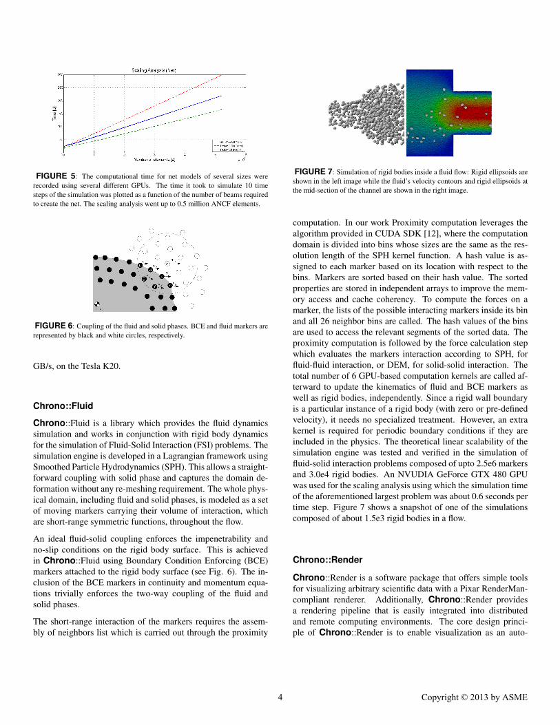
FIGURE 5: The computational time for net models of several sizes wererecorded using several different GPUs. The time it took to simulate 10 timesteps of the simulation was plotted as a function of the number of beams requiredto create the net. The scaling analysis went up to 0.5 million ANCF elements.
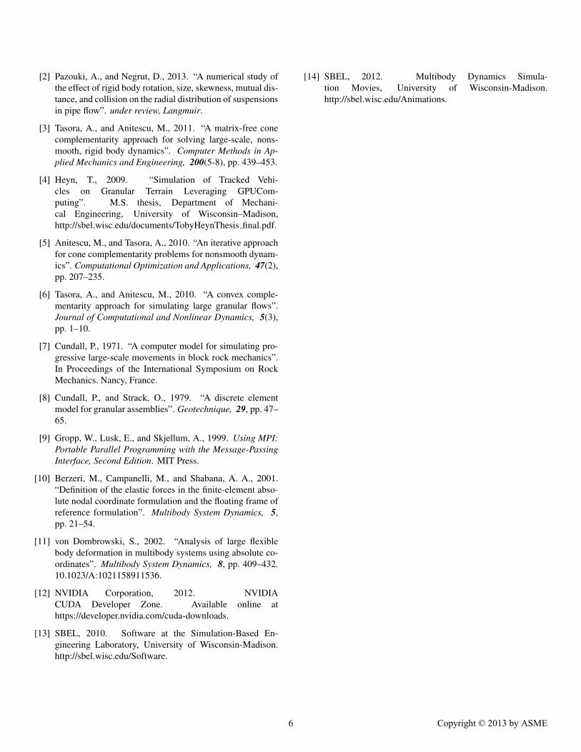
FIGURE 6: Coupling of the fluid and solid phases. BCE and fluid markers arerepresented by black and white circles, respectively.
GB/s, on the Tesla K20.
Chrono::Fluid
Chrono::Fluid is a library which provides the fluid dynamicssimulation and works in conjunction with rigid body dynamicsfor the simulation of Fluid-Solid Interaction (FSI) problems. Thesimulation engine is developed in a Lagrangian framework usingSmoothed Particle Hydrodynamics (SPH). This allows a straight-forward coupling with solid phase and captures the domain de-formation without any re-meshing requirement. The whole phys-ical domain, including fluid and solid phases, is modeled as a setof moving markers carrying their volume of interaction, whichare short-range symmetric functions, throughout the flow.
An ideal fluid-solid coupling enforces the impenetrability andno-slip conditions on the rigid body surface. This is achievedin Chrono::Fluid using Boundary Condition Enforcing (BCE)markers attached to the rigid body surface (see Fig. 6). The in-clusion of the BCE markers in continuity and momentum equa-tions trivially enforces the two-way coupling of the fluid andsolid phases.
The short-range interaction of the markers requires the assem-bly of neighbors list which is carried out through the proximity
FIGURE 7: Simulation of rigid bodies inside a fluid flow: Rigid ellipsoids areshown in the left image while the fluid’s velocity contours and rigid ellipsoids atthe mid-section of the channel are shown in the right image.
computation. In our work Proximity computation leverages thealgorithm provided in CUDA SDK [12], where the computationdomain is divided into bins whose sizes are the same as the res-olution length of the SPH kernel function. A hash value is as-signed to each marker based on its location with respect to thebins. Markers are sorted based on their hash value. The sortedproperties are stored in independent arrays to improve the mem-ory access and cache coherency. To compute the forces on amarker, the lists of the possible interacting markers inside its binand all 26 neighbor bins are called. The hash values of the binsare used to access the relevant segments of the sorted data. Theproximity computation is followed by the force calculation stepwhich evaluates the markers interaction according to SPH, forfluid-fluid interaction, or DEM, for solid-solid interaction. Thetotal number of 6 GPU-based computation kernels are called af-terward to update the kinematics of fluid and BCE markers aswell as rigid bodies, independently. Since a rigid wall boundaryis a particular instance of a rigid body (with zero or pre-definedvelocity), it needs no specialized treatment. However, an extrakernel is required for periodic boundary conditions if they areincluded in the physics. The theoretical linear scalability of thesimulation engine was tested and verified in the simulation offluid-solid interaction problems composed of upto 2.5e6 markersand 3.0e4 rigid bodies. An NVUDIA GeForce GTX 480 GPUwas used for the scaling analysis using which the simulation timeof the aforementioned largest problem was about 0.6 seconds pertime step. Figure 7 shows a snapshot of one of the simulationscomposed of about 1.5e3 rigid bodies in a flow.
Chrono::Render
Chrono::Render is a software package that offers simple toolsfor visualizing arbitrary scientific data with a Pixar RenderMan-compliant renderer. Additionally, Chrono::Render providesa rendering pipeline that is easily integrated into distributedand remote computing environments. The core design princi-ple of Chrono::Render is to enable visualization as an auto-
4 Copyright © 2013 by ASME
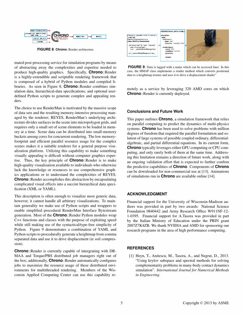
FIGURE 8: Chrono::Render architecture.
mated post-processing service for simulation programs by meansof abstracting away the complexities and expertise needed toproduce high-quality graphics. Specifically, Chrono::Renderis a highly-extendible and scriptable rendering framework thatis composed of a hybrid of Python modules and compiled li-braries. As seen in Figure 8, Chrono::Render combines sim-ulation data, hierarchical-data specifications, and optional user-defined Python scripts to generate complex and appealing ren-ders.
The choice to use RenderMan is motivated by the massive scopeof data sets and the resulting memory-intensive processing man-aged by the renderer; REYES, RenderMan’s underlying archi-tecture divides surfaces in the scene into micropolygon grids, andrequires only a small set of scene elements to be loaded in mem-ory at a time. Scene data can be distributed into small-memorybuckets among cores for concurrent rendering. The low memory-footprint and efficient parallel resource usage for the complexscenes makes it a suitable renderer for a general purpose visu-alization platform. Utilizing this capability to make somethingvisually appealing is difficult without computer graphics exper-tise. Thus, the key principle of Chrono::Render is to makehigh-quality visualization available to individuals who otherwiselack the knowledge or resources to use comprehensive graph-ics applications or to understand the complexities of REYES.Chrono::Render accomplishes this abstraction by encapsulatingcomplicated visual effects into a succint hierarchical data speci-fication (XML or YAML).
This description is often enough to visualize most generic data,however, it cannot handle all arbitrary visualizations. To main-tain generality we make use of Python scripts and wrappers toenable simplified procedural RenderMan Interface Bytestreamgeneration. Most of the Chrono::Render Python modules wrapC++ functions and classes with the purpose of exploiting speedwhile still making use of the syntactical/type-free simplicity ofPython. Figure 9 demonstrates a combination of YAML andPython scripts to procedurally generate a heightmap from commaseparated data and use it to drive displacement (ie soil compres-sion).
Chrono::Render is currently capable of intergrating with DR-MAA and Torque/PBS distributed job managers right out ofthe box; additionally, Chrono::Render automatically configuresjobs to maximize the resource usage of these distributed envi-ronments for multithreaded rendering. Members of the Wis-consin Applied Computing Center can use this capability re-
FIGURE 9: Data is tagged with a name which can be accessed later. In thiscase, the HMAP class implements a render method which converts positionaldata to a heightmap texture and uses it to drive a displacement shader”
motely as a service by leveraging 320 AMD cores on whichChrono::Render is currently deployed.
Conclusions and Future Work
This paper outlines Chrono, a simulation framework that relieson parallel computing to predict the dynamics of multi-physicssystems. Chrono has been used to solve problems with milliondegrees of freedom that required the parallel formulation and so-lution of large systems of possible coupled ordinary, differential-algebraic, and partial differential equations. In its current form,Chrono typically leverages either GPU computing or CPU com-puting, and only rarely both of them at the same time. Address-ing this limitation remains a direction of future work, along withan ongoing validation effort that is expected to further confirmthe predictive capabilities of Chrono. Components of Chronocan be downloaded for non-commercial use at [13]. Animationsof simulations run in Chrono are available online [14].
ACKNOWLEDGMENT
Financial support for the University of Wisconsin-Madison au-thors was provided in part by two awards: National ScienceFoundation 0840442 and Army Research Office W911NF-12-1-0395. Financial support for A.Tasora was provided in partby the Italian Ministry of Education under the PRIN grant2007Z7K4ZB. We thank NVIDIA and AMD for sponsoring ourresearch programs in the area of high performance computing.
REFERENCES
[1] Heyn, T., Anitescu, M., Tasora, A., and Negrut, D., 2013.“Using krylov subspace and spectral methods for solvingcomplementarity problems in many-body contact dynamicssimulation”. International Journal for Numerical Methodsin Engineering.
5 Copyright © 2013 by ASME
[2] Pazouki, A., and Negrut, D., 2013. “A numerical study ofthe effect of rigid body rotation, size, skewness, mutual dis-tance, and collision on the radial distribution of suspensionsin pipe flow”. under review, Langmuir.
[3] Tasora, A., and Anitescu, M., 2011. “A matrix-free conecomplementarity approach for solving large-scale, nons-mooth, rigid body dynamics”. Computer Methods in Ap-plied Mechanics and Engineering, 200(5-8), pp. 439–453.
[4] Heyn, T., 2009. “Simulation of Tracked Vehi-cles on Granular Terrain Leveraging GPUCom-puting”. M.S. thesis, Department of Mechani-cal Engineering, University of Wisconsin–Madison,http://sbel.wisc.edu/documents/TobyHeynThesis final.pdf.
[5] Anitescu, M., and Tasora, A., 2010. “An iterative approachfor cone complementarity problems for nonsmooth dynam-ics”. Computational Optimization and Applications, 47(2),pp. 207–235.
[6] Tasora, A., and Anitescu, M., 2010. “A convex comple-mentarity approach for simulating large granular flows”.Journal of Computational and Nonlinear Dynamics, 5(3),pp. 1–10.
[7] Cundall, P., 1971. “A computer model for simulating pro-gressive large-scale movements in block rock mechanics”.In Proceedings of the International Symposium on RockMechanics. Nancy, France.
[8] Cundall, P., and Strack, O., 1979. “A discrete elementmodel for granular assemblies”. Geotechnique, 29, pp. 47–65.
[9] Gropp, W., Lusk, E., and Skjellum, A., 1999. Using MPI:Portable Parallel Programming with the Message-PassingInterface, Second Edition. MIT Press.
[10] Berzeri, M., Campanelli, M., and Shabana, A. A., 2001.“Definition of the elastic forces in the finite-element abso-lute nodal coordinate formulation and the floating frame ofreference formulation”. Multibody System Dynamics, 5,pp. 21–54.
[11] von Dombrowski, S., 2002. “Analysis of large flexiblebody deformation in multibody systems using absolute co-ordinates”. Multibody System Dynamics, 8, pp. 409–432.10.1023/A:1021158911536.
[12] NVIDIA Corporation, 2012. NVIDIACUDA Developer Zone. Available online athttps://developer.nvidia.com/cuda-downloads.
[13] SBEL, 2010. Software at the Simulation-Based En-gineering Laboratory, University of Wisconsin-Madison.http://sbel.wisc.edu/Software.
[14] SBEL, 2012. Multibody Dynamics Simula-tion Movies, University of Wisconsin-Madison.http://sbel.wisc.edu/Animations.
6 Copyright © 2013 by ASME