Embed Size (px)
Citation preview

© ABB Group May 29, 2012 | Slide 1
Global sales program Bay control solutions
Stefan Meier, Substation Automation Systems, 2012-05-29

© ABB Group May 29, 2012 | Slide 2
Content
Introduction
Control concepts and functions
Control IED portfolio
Positioning of control devices
RTU control application examples

© ABB Group May 29, 2012 | Slide 3
Introduction Function allocation
Sta
tio
n
level
Bay l
evel
Pro
cess
level
Functional allocation
Station automation
Monitoring
Fault evaluation
Event & alarm viewing
and acknowledgement
Remote communication for
telecontrol & supervision
Protection
Control
Monitoring
Interlocking
Data acquisition
GIS or AIS switchgear
Instrument transformers
Power transformers
Surge arresters
Non-conventional transf.

© ABB Group May 29, 2012 | Slide 4
Introduction Technology evolution
RTU RTU RTU
RTU RTU RTU
parallel,hardwired
cabling
parallel,hardwired
cabling
parallel,hardwired
cabling
Interbay Bus Interbay Bus
Process Bus
Station Bus Station Bus

© ABB Group May 29, 2012 | Slide 5
What is bay control?

What is bay control
Safe operation of a substation switching device to bring the
substation from a current state to the desired end-state.
Relevant considerations
Status of the substation (persisting alarm conditions, on-
going maintenance activities)
Status and capabilities of the switching equipment
(position indications, CB operating capabilities)
Interlocking conditions to assure personal safety and avoid
damage to the equipment
Control priorities and authority of different operating places
Coordination with protection devices (persisting protection
trips)
Supervision of the switchgear and notification of the users (runtime
supervision, trip-coil supervision, CB monitoring, SF6 supervision,
…)
© ABB Group May 29, 2012 | Slide 6

Control of substations From local to remote control
© ABB Group May 29, 2012 | Slide 7
Marshalling kiosk
Signal marshalling
and local control
per feeder
Drive box
Local control of one
breaker /
disconnector
directly on the
motor drive
Relay house
Control panel in
Relay house in the
switchyard, eg one
house per diameter
Protection room
Control panel may
also be located in a
central protection
room
Network control
centre
Remote control of
several substations
from national or
regional control centres
Station automation
system
Remote control of the
entire substation from
the SAS
From local to remote,
with decaying priority

Control of substations Control locations in a AIS substation (1 ½ breaker, transmission level)
© ABB Group May 29, 2012 | Slide 8
1 per
CB
1 per diameter
Drive box
Local control of one
breaker /
disconnector
directly on the
motor drive
Marshalling kiosk
Signal marshalling
and local control
per feeder
Relay house
Protection and
control of one feeder
in Relay house in the
switchyard
Station automation
system
Remote control of the
entire substation from
the SAS
1 per substation
1 per
CB
1 per
CB

Control of substations Control locations in a GIS substation (1 ½ breaker, transmission level)
© ABB Group May 29, 2012 | Slide 9
Drive box
Local control of one
breaker /
disconnector
directly on the
motor drive
Station automation
system
Remote control of the
entire substation from
the SAS
1 per substation
Protection room
Control panel may
also be located in a
central protection
room
Local control
Control panel next
to or integrated in
the GIS switchgear
1 per substation
1 per
CB
1 per
CB
1 per
CB

© ABB Group May 29, 2012 | Slide 10
Control concepts and functions

© ABB Group May 29, 2012 | Slide 11
Control concepts Content
Control concepts
Conventional and modern control
Basic control philosophy

© ABB Group May 29, 2012 | Slide 12
Control concepts Introduction
Remote control Local integrated control Local control
Switchgear type
GIS/AIS GIS/AIS GIS
Typical application
Sub-transmission/
transmission
Distribution Transmission
Layout
Control cubicle in relay room,
AIS with marshalling cubicle
IED installed in switchgear panel LCC attached to or installed next
to GIS
Functions of control
IED
Control, sometimes with backup
or main2 protection
Protection and control in one IED Control, sometimes with backup
or main2 protection
ABB IEDs
REC650, REC670 REF615, REF630 REC670

© ABB Group May 29, 2012 | Slide 13
Control concepts Conventional and modern control
Conventional
Bay control mimic
Seamless integration into Substation
Automation Systems through IEC61850
for remote control and supervision
Allows integrated functionalities like
synchrocheck, autoreclosure and backup
protection
Future prove, as they allow integration of
non-conventional current and voltage
transformers
Modern
Bay control IED
Hardwired connection to separate remote
control panel or RTU system
Dedicated equipment required for
additional functionality
Simple but limited technology, relying on
discrete electromechanical equipment

© ABB Group May 29, 2012 | Slide 14
Control concepts Conventional and modern control
Conventional LCC
Normally used if integration into SA
system is not in scope of LCC supplier
The Bay Controller is located in a
separate remote control cubicle (RCC)
High overall space requirement for
LCC and RCC
-
QA1
-
QC2
-QC1
-
QB61
-
QB62
-T2
-T1
-
QA1-
QC2
-QC1
-
QB6
-
QB2
-T1
BBII
-
QB9
-QC9-
QA1
-
QC2
-
QC1
-
QB1
-
QB6
-T1
BBI
-
QB9
-
QC9
A
B B
A
B
A
B B
ABBABBABB
ABB ABB ABBABB ABB
ABB
Local
Control
Cubicle
Protection
Cubicle
IEC61850
Remote
Control
Cubicle
Modern LCC (combination of LCC and
RCC)
Direct integration of LCC into station
automation system
Less overall space for panels required
Fewer inter-panel cabling
Lower overall cost

© ABB Group May 29, 2012 | Slide 15
Control concepts Basic SA control philosophy
-Q1 -Q0 -Q8 -Q9
-Q2
DCB
Station automation solution (SAS)
Bay l
ev
el
Gateway
Pro
cess lev
el
Local control
Emergency control
Sta
tio
n lev
el
Station level
Remote control via station computer or
independent gateway
Station control via SAS
Bay level
Local control via IED display
Emergency control (independent from IED)
via conventional mimic or control buttons
Process level
Emergency control function in drive control
boxes depending type and supplier
(e.g. crank handle or push buttons)
DCB
Co
ntr
ol
pri
ori
ty
Hig
h
Lo
w
DCB DCB DCB

© ABB Group May 29, 2012 | Slide 16
Bay control functions Content
Function overview
Remote control interface
Protection Interface
Local control facilities
SA control philosophy
Local alarm indication
Marshaling
Drive Control
Supervision function
Interlocking

© ABB Group May 29, 2012 | Slide 17
Bay control functions Function overview
Local Control Cubicle
Drive
control
Marshaling
Emergency
control
Interface to
remote
Interface to
remote
Control and
HMI Protection
Drive
control
The various functions of a
control solution can be
allocated to different panels
and devices, depending on
the station layout and
requirements

© ABB Group May 29, 2012 | Slide 18
Remote control interface For conventional solutions
Parallel interface for remote control
via RTU or bay controller (placed in
a separate cubicle)
Parallel interface in conventional
solutions includes:
Position indication of each
primary equipment
On / Off command for each
primary equipment
Alarms as on local annunciator
Control authority status /
Interlocking override status
Drive auxiliary contacts from
primary equipment
(1:1 wired to terminals, free usable
for customer)
Hardwired interface for station
interlocking
Drive
Control
Marshaling
Emergency
Control
Interface to
Remote
Primary Equipment Interface
Protection
Interface
Bay
Control
Drive
Control
RTU or
bay control IED
HW station interlocking

© ABB Group May 29, 2012 | Slide 19
Remote Control Interface For modern solutions
IEC61850 communication interface
to station bus
Communication to station
automation system (SAS)
Reporting of events, alarm,
status information,
measurements
Control commands from SAS
Configuration of control IED
Reading of disturbance
records, IED maintenance
information
Bay to bay communication
(GOOSE)
Double operation blocking
Interlocking
Drive
Control
Marshaling
Emergency
Control
Interface to
Remote
Primary Equipment Interface
Protection
Interface
Bay
Control
Drive
Control
Station bus (SAS, interlocking)

© ABB Group May 29, 2012 | Slide 20
Drive
Control
Marshaling
Emergency
Control
Interface to
Remote
Primary Equipment Interface
Protection
Interface
Bay
Control
Drive
Control
Protection Interface
Protection interface for all status information and
control circuits who are required for the
protection solution
CT / VT circuits
Trip I & II circuits
Trip and Close circuit supervision interface
Autoreclosure command
Manual close, VT MCB status, CB position
status
OCO Ready, CB Ready, CB and BB
disconnector position for Autoreclosure and
Synchrocheck
Manual close, CB and BB disconnector
position for BBP / BFP protection
Protection status information for alarm
indication in the LCC
All drive position indications for protection
come from primary apparatus auxiliary
contacts
To protection

© ABB Group May 29, 2012 | Slide 21
Bay control functions Local control facilities
IED HMI
Visualization of single line, measurements, alarms,
events, parameters
Local control of the feeder with function buttons
Mimic with direct control
Control object status indication with LED’s
Display of measurements
Operation authority (Local, Remote, Off)
Local control via control buttons (select before
operate or two-hand-operation)
Independent of IED
CB emergency control
Direct control buttons with authority key switch
Independent of IED Circuit Breaker
Close Command
Circuit Breaker
Open Command
Circuit Breaker
Pump Reset
Authority Switch

© ABB Group May 29, 2012 | Slide 22
Bay control functions Select before operate concept
+
-Q1
-Q0
-Q8
-Q9
-Q2
1 2
Selection
At selection of an object, control
conditions is verified by the IED
Double operation blocking is sent out
independent output is executed
(minus circuit)
3 Execution
Execution command is verified in the
IED
independent output is executed (plus
circuit), the breaker/ disconnector
operates
The select before operate concept
guaranties a maximum of operation
safety!
1
2
3

© ABB Group May 29, 2012 | Slide 23
Bay control functions Select before operate concept – enhanced security
ABB’s 650 and 670 series
IEDs support SBO with
enhanced security
Normal security:
only the command is
evaluated and the
resulting position is not
supervised.
Enhanced security
command sequence is
supervised in three
steps, the selection,
command evaluation
and the supervision of
position.

Bay control functions Synchronizing and synchrocheck
Synchrocheck, energizing check, and
synchronizing function (SESRSYN) checks
that the voltages on both sides of the circuit
breaker are in synchronism
© ABB Group May 29, 2012 | Slide 24
RSYN
RSYN, energizing
RSYN, synchrocheck
RSYN, synchronizing
Energizing check releases CB closing if one
side of the CB is de-energized
Synchrocheck releases CB closing if delta
values across the CB are within defined limits
Voltage level difference.
Frequency difference (slip)
Phase angle difference.
Synchronizing functionality is used if
frequency difference across the CB is bigger
than allowed by the synchrocheck function
(and lower than max limit)
Close command is issued at optimum
time to close when phase difference is
within limits

© ABB Group May 29, 2012 | Slide 25
Bay control functions Local alarm indication
Fault indication with 16 LED’s
Annunciator with push buttons for..
Lamp test
LED’s acknowledgement
Horn acknowledgement
Fault indication of …
Protection information (tripped,
disturbed)
Circuit breaker information (spring
blocked, SF6 blocked, TCS failed,
pole discrepancy)
SF6 gas (refill, urgent disconnect)
MCB status (AC, DC, VT)
Crank handle in use Modern solution
Conventional solution

© ABB Group May 29, 2012 | Slide 26
Drive
Control
Marshaling
Emergency
Control
Interface to
Remote
Primary Equipment Interface
Protection
Interface
Bay
Control
Drive
Control
Bay control functions Marshaling
Marshaling of:
DC supply
LCC internal
Switchgear drives
AC supply
LCC light
LCC heater
drive heater
CT / VT circuits (VTs are
protected with MCBs)
SF6 gas compartment status
Grouping of SF6 gas refill
Grouping of SF6 urgent
disconnect

© ABB Group May 29, 2012 | Slide 27
Drive
Control
Marshaling
Emergency
Control
Interface to
Remote
Primary Equipment Interface
Protection
Interface
Bay
Control
Drive
Control
Drive control Overview
Drive control includes …
Circuit breaker control and
supervision
Hydraulic pump control and
supervision
Disconnector and earthing
switch control

© ABB Group May 29, 2012 | Slide 28
Drive control Circuit breaker control and supervision
Anti-pumping control
Prevents the repeated undesired closing of a breaker in case
the CB is in open position and open command persists
protect the CB from toggling
Circuit-breaker blocking
Closing and tripping circuits will blocked by low SF6 gas
pressure
If spring-pressure below O-C-O
autoreclosure circuit will be blocked
If spring-pressure below C-O
close operation will be blocked
If spring-pressure below O
trip circuit will be blocked
Pole discrepancy function
Detects a discrepancy in the pole positions of the CB
activation of three phase trip command
Interlocking

© ABB Group May 29, 2012 | Slide 29
Drive control Hydraulic pump control and supervision
Pump start cascading
Simultaneous start of the three pumps, would generate high
peak load on the DC battery
250ms time delay between pump starts
Pump start supervision
If more than 10 unforced pump operations (without CB
operation) occur within 24h, an alarm will be generated
Hydraulic system has to be checked
The Pump Reset button at the mimic will light up continuously
Pump runtime supervision
At each pump start, it is supervised whether the spring is fully
charged after 2 minutes. If not, the PLC will block all pumps
Pumps will be protected from overheating
The Pump Reset button at the mimic will light up continuously
Pump start counter
Circuit breaker operation counters
For HMB
CB operating
mechanisms

© ABB Group May 29, 2012 | Slide 30
Bay control functions Supervision function example – SF6 density
Supervision of SF6 density
in circuit breaker and GIS
2 Binary alarm levels
Refill alarm
Urgent disconnect
Analog (4..20mA)
signals for trending and
enhanced supervision
Often dedicated
systems due to the
high number of
signal inputs (~18
per transmission
GIS feeder)
Sta
nda
rd f
un
ction
Specia
l fu
nction
Binary signals to
control and
protection
4...20 mA

© ABB Group May 29, 2012 | Slide 31
Bay control functions Supervision function example – CB monitoring
Monitoring of CB condition
Typically supervised
values:
Breaker contact travel
time
Operation counter
Accumulated opened
energy
SF6 density
Trip curve for typical 12kV, 16kA CB
Specia
l fu
nction

Bay control functions Interlocking
Blocking:
command block of a switch because of conditions
concerning this switch only.
Examples: gas density, switching energy, defect switch,
defect back indications etc.
Interlocking:
command block of a switch because of other switch
positions in the switch yard
Examples: closed earth switches, moving switches,
busbar transfer etc.
© ABB Group May 29, 2012 | Slide 32

© ABB Group May 29, 2012 | Slide 33
Bay control functions Interlocking
Interlocking blocks the operation of switching devices to:
prevent danger to human life
prevent damage to the switchgear
assure meaningful protection operation
avoid unnecessary operation of switching devices
Bay interlocking (bay-internal switch positions)
Station interlocking (bay-external switch positions):
via hardwired station interlocking bus
via communication bus IEC61850

© ABB Group May 29, 2012 | Slide 34
Bay control functions Interlocking
Basic principles
Disconnectors shall not be opened or closed on-load
Earthing switches shall not be closed onto voltage
CBs shall not be closed when surrounding disconnectors are in intermediate positions
CB opening is only interlocked at a bus-coupler bay, if a busbar transfer is in progress

© ABB Group May 29, 2012 | Slide 35
Bay control functions Interlocking
Safety aspects
All switch positions are transferred as double indications
Single defects (eg, loose wire) do not cause wrong behaviour
Switching releases may be transferred as double indications
Single errors (eg, loose wire) lead to blocking of operation
Consider unknown states
Unknown states need to be verified and failure is in the process or the control system need to be repaired. Otherwise a second failure in the control system may lead to unsafe situations.

© ABB Group May 29, 2012 | Slide 36
Station interocking Hardwired and IEC 61850 GOOSE
Control Control Control
IEC 61850
station bus
Hardwired
station bus
Control Control Control
IEC 61850
station bus
GOOSE GOOSE
Distribution of information
between bays is done
through auxiliary contacts
and parallel wiring
All information is
exchanged through the IEC
61850 station bus network

© ABB Group May 29, 2012 | Slide 37
Station interocking GOOSE example
Disc QB1 and QB2 closed
WA1 not earthed
WA2 not earthed
WA1 and WA2 interconn.
Disc QB1 and QB2 closed
WA1 not earthed
WA2 not earthed
WA1 and WA2 interconn. . . . . .
Station bus
QB1
WA1
WA2
Bay 1 Bay n Bus coupler
WA1 unearthed
WA1 unearthed WA1 and WA2 interconn.
WA1 and WA2 interconnected
in other bay
QB2
QA1
QB9
QB1 QB2
QA1
QB9
QB2 QB1
QA1
QC1 QC2

© ABB Group May 29, 2012 | Slide 38
Station interlocking IEC61850 interbay bus (GOOSE)
IEC 61850-8-1
GOOSE
Generic Object Oriented Substation
Event
Testing without GOOSE simulator is
difficult/ expensive
Extension of existing installation or
stepwise extensions may require
configuration changes in each IED
In case an IED is switched off, the
status information of the affected
feeder are missing (maintenance)
No wiring between panels
No additional I/Os required for
station interlocking information
Additional information can be
transmitted e.g. double operation
interlocking, disturbance recorder
triggering etc.
All signals are continuously
supervised
Advantages Challenges

© ABB Group May 29, 2012 | Slide 39
Station interlocking Hardwired interlocking bus
IEC 61850-8-1
Hardwired Interlocking Bus
More cabling between panels
Additional I/Os required for station
interlocking information
More auxiliary contacts required on
CB/ disconnector/ earth switch
drives
External power supply in all panels
for station interlocking bus (e.g.
from bus coupler)
Simple testing
Easy for future extensions or
stepwise commissioning (no
changes of the IED configuration
required)
Maximum availability because
position information on the
hardwired bus are direct from the
primary equipment and
not via an IED
Advantages Disadvantages

© ABB Group May 29, 2012 | Slide 40
Control IED portfolio

© ABB Group May 29, 2012 | Slide 41
Application, Price,
Functionality,
Performance
REC670
REC650
REF630
REC601/3
REF615
Sub-transmission Transmission Distribution
Control devices Overview

REC601/603 Control in automated distribution networks
Wireless Controllers REC601/603 for automated distribution
network
Local and remote control and monitoring of up to three (3)
objects (REC603)
Disconnector and earting indications with front LEDs
More than one REC601/603 can be connected in a single
location to facilitate the Ethernet enabled control and
monitoring of more disconnectors
Overload protection of actuator motors
Load current measured in the motor circuit
Energy limit based motor overload protection (“software
fuse”)
Always-on two-way communication based on GPRS
Redundant IEC 60870-5-104 connections
High level data security through internal VPN and Firewall
Possibility to act as an IEC 60870-5-101 master (router) for
another communicating sub-device
Built-in battery charger
Heater control to limit effects of ambient temperature variations
Real-time clock for accurate event time-tagging
© ABB Group May 29, 2012 | Slide 42

615 series Control and protection in distribution substations
Control of one circuit-breaker (CB) via the IED’s
human-machine interface (HMI) or a remote control
system
Interlocking schemes
Predefined configurations can be modified in
PCM600 graphical application configuration (ACT)
Designed for IEC 61850
Binary and analog GOOSE messaging
REF615 also supports:
Modbus®
DNP3
IEC 60870-5-103
An optional second Ethernet bus enables the
creation of a self-healing Ethernet ring
Optional three-channel arc protection system
© ABB Group May 29, 2012 | Slide 43
REF615 feeder protection
and control IED
RED615 line differential
protection and control IED
RET615 transformer
protection and control IED
REU615 voltage protection
and control IED
REM615 motor protection
and control IED
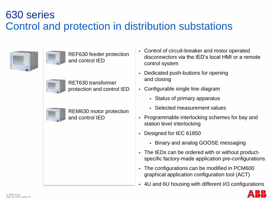
630 series Control and protection in distribution substations
Control of circuit-breaker and motor operated
disconnectors via the IED’s local HMI or a remote
control system
Dedicated push-buttons for opening
and closing
Configurable single line diagram
Status of primary apparatus
Selected measurement values
Programmable interlocking schemes for bay and
station level interlocking
Designed for IEC 61850
Binary and analog GOOSE messaging
The IEDs can be ordered with or without product-
specific factory-made application pre-configurations
The configurations can be modified in PCM600
graphical application configuration tool (ACT)
4U and 6U housing with different I/O configurations
© ABB Group May 29, 2012 | Slide 44
REF630 feeder protection
and control IED
RET630 transformer
protection and control IED
REM630 motor protection
and control IED

REC650 Control in sub-transmission substations
Apparatus control for up to 8 apparatus with
integrated backup protection
Ready-to-use configured IEDs for 3 network
configurations
The configurations can be modified in PCM600
graphical application configuration tool (ACT)
Designed for IEC 61850
Binary GOOSE messaging
Safe and dependable reservation method for
apparatus control
Well proven standard interlocking functions
Powerful and extensive HMI functionality eliminates
the need for external mimic boards
© ABB Group May 29, 2012 | Slide 45
REC650 bay control IED
REL650 line distance
protection IED *
RET650 transformer
protection IED *
REQ650 breaker
protection IED *
REG650 generator
protection IED *
* Without control functions

REC670 Control in sub-transmission & transmission substations
Local and remote control of up to 6 bays and 30
apparatus
Extensive function library according to IEC 61850
Extensive analog and binary I/O capability
Completely configurable to the most demanding applications
Designed for IEC 61850
Binary GOOSE messaging
Select before operate with enhanced security
Well proven standard interlocking functions
Powerful and extensive HMI functionality eliminates
the need for external mimic boards
Integration of non-conventional instrument
transformers using IEC 61850-9-2LE
Control functions are also available in the protection
IEDs
© ABB Group May 29, 2012 | Slide 46

RTU560/RTU211 Control in distribution, sub-transmission & transmission substations
Various communication interfaces
Selectable RS232/RS485 interfaces
Ethernet 10/100 Mbps interface
SDSL modem, GPRS modem, fiber optic, FSK
modems
Wide range of host and client protocols
IEC 61850 as client or server with proxy
functionality
Integrated web server for diagnosis, administration,
archive and HMI
Programmable logic controller (PLC) according to
IEC 61131-3
Rack based solution
Very flexible, compact and space saving solution
Redundant power supply, CPU and host communication options
Cost efficient for medium and larger systems
DIN rail mounted solution
Low space requirements
Cost efficient for low end and small applications © ABB Group May 29, 2012 | Slide 47

© ABB Group May 29, 2012 | Slide 48
Positioning of control devices

Control IED portfolio Content
Overall positioning
Details REC650/REC670 and their positioning
© ABB Group May 29, 2012 | Slide 49

Devices for control Overview
© ABB Group May 29, 2012 | Slide 50
Functions REC670 REC650 REF630 REF615 REC601/603 RTU560 rack
RTU560/211
DIN rail
Transmission
Sub-transmission
Distribution
Secondary distribution
Controllable bays 6 1 1 1 1 “unlimited” “unlimited”
Controllable objects 30 (6CBs) 8 (1CB) 10 (2CBs) 1CB
(indication of 3DS, 1ES)
3 “unlimited” “unlimited”
Max. binary Inputs/outputs 208/961) 50/451) 50/451)2) 18/131) 5000 datapoints 750 datapoints
Max. analog inputs 241) 101) 101)2) 91)
Automatic voltage control
of parallel transformers yes (RET650) (RET630) (RET615)
External or PLC
program
External or PLC
program
Protection Main & backup Backup Main & backup Main & backup external external
Tripping type 1ph & 3ph 3ph 3ph 3ph 3ph
Pre-configurations
IEC 61850 station bus
NCC/DMS communication
GSM/GPRS modem integr
1) The maximum numbers are influencing each other and are mutually exclusive. 2) Numbers are for 6U casing. Less I/Os for 4U casing

© ABB Group May 29, 2012 | Slide 52
Tap changer control Protection IED Control IED
AR, backup protection Protection IED Control IED
Synchrocheck Protection IED Control IED
WebHMI control RTU RTU as IEC 61850 client
Interlocking Hardwired
RTU (and hardwired)
Control IED
Remote control
Hardwired interface
RTU
IEC 61850
Control IED
IEC 61850
Local control
Bay control mimic Bay control mimic Control IED Display
Control concept
Conventional Conventional with RTU Modern with IED
Bay control Overview: Functions and control concepts
Control functions
REC670
RTU
Conventional
LCC

© ABB Group May 29, 2012 | Slide 53
Pro
tectio
n
Syn
c, A
R
U/I
me
as
IEC
61
85
0
GP
RS
--
-- --
--
--
-- --
-- -- -- --
Controllable objects
1 Object (3 indications) 10 Objects (2CB) 8 Objects (1CB) 15 Objects (2CB) 30 Objects (6CB) Voltage level
secondary distribution distribution sub-transmission transmission
Bay control Overview: functions, controllable objects, voltage levels
Functions
REC601/603
RTU
REF615
REF630
REC650
REC670

Control IED portfolio Content
Overall positioning
Details REC650/REC670 and their positioning
© ABB Group May 29, 2012 | Slide 54

© ABB Group May 29, 2012 | Slide 55
REC670 control Pre-configured solutions
REC670 Control Pre-Configured Solutions
Main Functions A30 B30 C30
Physical arrangement Single-breaker
(double/sing. bus) Double breaker 1 ½ Breaker
1Ph high impedance differential protection option option option
Four step phase and residual overcurrent protection option option option
Thermal overload one/two time constants option option option
Breaker failure and under/over power protection option option option
Under/over voltage, under/over df/dt frequency option option option
Auto-reclose option option option
Synchrocheck ● ● ●
Apparatus control for single bay, max 8 apparatuses
(1CB) incl. interlocking ●
Apparatus control for single bay, max 15 apparatuses (2CBs)
incl. interlocking ●
Apparatus control for up to 6 bays, max 30 apparatuses
(6CBs) incl. interlocking ●
Automatic voltage control for tap changer, single/parallel option option option
Tap changer control ● ● ●
Fault locator option option option
=QA1
=QB1 =QB2
=QB9
=QC9
=Q1

© ABB Group May 29, 2012 | Slide 56
REC650 bay control Configured solutions
REC650 Bay Control Configured Solutions
Main Functions A01 A02 A07
Physical arrangement Single breaker
single busbar
Single breaker
double busbar
Bus coupler
double busbar
Interlocking for line bay ● ● ●
Interlocking for transformer bay ● ● ●
Interlocking for bus coupler bay ● ● ●
Interlocking for 1 1/2 breaker diameter ● ● ●
Interlocking for double CB bay ● ● ●
Four step phase and residual overcurrent protection ● ● ●
Thermal overload protection, one time constant ● ● ●
Breaker failure and stub protection ● ● ●
Under/over voltage, under/over df/dt frequency ● ● ●
Auto-reclose and synchrocheck ● ● ●
=QA1
=QB1 =QB2
=QB9
=QC9
=Q1

© ABB Group May 29, 2012 | Slide 57
Bay control Communication comparison
Communication Product Family
Station communication REC670 REC650
SPA communication protocol ●
LON communication protocol ●
IEC 60870-5-103 communication protocol ● ●
Selection between SPA/IEC60870-5-103/DNP for SLM ●
DNP3.0 for TCP/IP and EIA-485 ● TCP/IP
DNP3.0 fault records for TCP/IP and EIA-485
communication protocol ● TCP/IP
DNP3.0 for serial optical communication protocol ●
IEC 61850-8-1 station bus communication ● ●
PRP redundant station bus communication ●
HSR redundant station bus communication
Horizontal communication via GOOSE for interlocking 59 59
GOOSE binary receive 10 4
Process bus communication
IEC 61850-9-2LE ●
Future

© ABB Group May 29, 2012 | Slide 58
Bay control Functionalities
Functionalities Product Family
Main Functions REC670 REC650
1Ph high impedance differential protection ●
Four step phase and residual overcurrent protection ● ●
Thermal overload one/two time constants ● one time constant
Breaker failure protection ● ●
Under/over voltage, under/over/ df/dt frequency ● ●
Auto-reclose and synchrocheck ● ●
Apparatus control for single bay, max 8 apparatuses
(1CB) incl. interlocking ● ●
Apparatus control for single bay, max 15 apparatuses
(2CBs) incl. interlocking ●
Apparatus control for up to 6 bays, max 30 apparatuses
(6CBs) incl. interlocking ●
Automatic voltage control for tap changer,
single/parallel ●
Tap changer control ●
Fault locator ●
=QA1
=QB1 =QB2
=QB9
=QC9
=Q1

© ABB Group May 29, 2012 | Slide 59
Bay control Positioning
Product REC670 REC650
Segment Transmission Subtransmission
Controllable objects, max 30 8
Controllable bays, max 6 1
Automatic voltage control of parallel
transformers ●
Reservation between bays Basic + Advanced Basic
Tripping type 1Ph and 3Ph 3Ph
Case size 6U ½ 19”, 6U ¾ 19”
6U 1/1 19” 6U ½ 19”
Setting groups 6 4
=QA1
=QB1 =QB2
=QB9
=QC9
=Q1

© ABB Group May 29, 2012 | Slide 60
Tap changer
control
1ph Backup
protection
Breaker failure
protection
Autoreclosure
3ph Backup
protection
Breaker failure
protection
Autoreclosure
CB and trip
circuit Monitoring
Controllable objects
1 6 Controllable bays
8 Objects (1CB) 15 Objects (2CB) 30 Objects (6CB) Controllable objects
REC650 and REC670 bay control IEDs Overview: Functions and controllable objects
Functions
REC670
REC650
REC650 REC650/670 REC670

© ABB Group May 29, 2012 | Slide 61
Multi feeder control
1 ½ breaker
1 IED per diameter
2 breaker arrangement
1 ½ breaker
1 IED per CB
2BB
single breaker
1BB
Casing and I/O
6U ½ 19” 6U ½ 19” 6U ¾ 19” 6U 1/1 19” Casing
50 321) 1121) 2081) Max. binary inputs
45 241) 961) 961) Max. binary outputs
10 12 241) 241) Max. analog inputs
0 0 241) 241) Max. mA inputs
REC650 and REC670 bay control IEDs Overview: Switchgear layout versus I/Os
Switchgear layout
REC650
REC670
1) The maximum numbers are influencing each other and
are mutually exclusive.
REC650 REC650/670 REC670

© ABB Group May 29, 2012 | Slide 62
Multi feeder control
1 ½ breaker
1 IED per diameter
2 breaker arrangement
1 ½ breaker
1 IED per CB
2BB
single breaker
1BB
Primary apparatus
1 drive, 3pole operated 1 drive, 1pole operated 3 drives, 1pole operated CB
3pole position indication 1pole position indication Fast acting ES
3pole position indication 1pole position indication DS/ES
Binary signals Analog signals (mA) Temp., density, …
REC650 and REC670 bay control IEDs Overview: Switchgear layout and primary apparatus
Switchgear layout
Case: 6U ½ 19”
Case: 6U ¾ 19”
Case: 6U 1/1 19”
REC670
REC650
REC650 REC650/670 REC670

© ABB Group May 29, 2012 | Slide 63
RTU control application examples

© ABB Group May 29, 2012 | Slide 64
Diagnosis IEC60870-5-101,
IEC60870-5-104, DNP3, DNP3 over WAN
Control system
Integrated HMI
IEC 61850-8-1
IEC 60870-5-103,
DNP3,
MODBUS
I/Os IEDs
IEDs
PLC
functions
Control level
Station level/ bay level
Communication level
Process
level
RTU application example RTU as Hybrid solution

RTU application example RTU in secondary distribution substations
© ABB Group May 29, 2012 | Slide 65
Covered functions
Remote control of distribution substation from
NCC/DMS
Wide range of communication media (eg,
GPRS modem)
Optional
U/I measurement by integrating transducer
interfaces
Overcurrent detection
Total harmonic distortion (THD)
PLC applications for voltage dip detection
Limitations
-
Suitable for
Remote control of secondary distribution
substations
Medium number of datapoints

RTU application example RTU in distribution substations
© ABB Group May 29, 2012 | Slide 66
WebHMI
IEC 61850
to SAS
or
NCC/DMS Covered functions
Remote control of distribution substation from
NCC/DMS or SAS
Optional
Local control for maintenance through RTU
WebHMI
Integration of IEC 61850 protection IEDs
U/I measurement by integrating transducer
interfaces
Limitations
Synchrocheck has to be performed by
dedicated devices or protection IEDs
Dedicated protection IEDs required
Suitable for
Retrofit of conventional SS
Remote control of simple SS with conventional
protection

RTU application example RTU in sub-transmission and transmission substations
© ABB Group May 29, 2012 | Slide 67
IEC 61850 to RTU or SAS
Local control
panels
Protection
panels
WebHMI
IEC 61850
to SAS
or
NCC
Covered functions
Remote control from NCC
Station control from SAS via IEC 61850, or
Station control from RTU WebHMI
Optional
Integration of IEC 61850 protection IEDs
Limitations
Synchrocheck has to be performed by
dedicated devices or protection IEDs
RTU time stamp accuracy does not meet
usually specified 1ms
Suitable for
Retrofit of conventional SS without changing
conventional control concept
Substation automation and simple control for
small sub-transmission/transmission
substations
Binary
I/O
Analog
inputs

© ABB Group May 29, 2012 | Slide 68
Bay control solutions

© ABB Group May 29, 2012 | Slide 69
Bay control functions Function allocation
ABB transmission GIS Other GIS AIS Remote Control Cubicle Local Control Cubicle Local Control Cubicle
Drive
control
Marshalling
Emergency
control
Interface to
remote
Interface to
remote
Control and
HMI Protection
Drive
control Drive
control
Marshalling
Emergency
control
Interface to
remote
Interface to
remote
Control and
HMI Protection
Drive
control
Drive
control
Marshalling
Emergency
control
Interface to
remote
Interface to
remote
Control and
HMI Protection
Drive
control
Marshalling Cubicle
Allocation of
functions and
equipment,
depending on
the controlled
switchgear

© ABB Group May 29, 2012 | Slide 70
BCS solution overview
BCS 652—local control and
protection cubicle in sub-
transmission substations
BPS 61x/63x—configured feeder
terminals for GIS and AIS in
distribution substations
BCS 651—configured control IED for GIS in sub-transmission substations
BCS 670—remote control
cubicle and marshalling kiosk for
AIS in transmission substations
BCS 690—local control cubicle
for GIS in transmission
substations
BCS 680—remote control
cubicle for GIS and AIS in
transmission substations

Bay control solutions Scope
© ABB Group May 29, 2012 | Slide 71
Control solutions
Marketing material
Base design docs
Detail design
Hardware
Detail design
Software
Test instructions
Templates and part drawings in E3
environment
IED configurations and I/O lists
Block diagrams
Presentations and brochures
Test instructions and reports

© ABB Group May 29, 2012 | Slide 72