Embed Size (px)
Citation preview
1 | P a g e
Nov 3, 2017
Chicane Coilover Kit
For ’67-69 Camaro/ Firebird/ ‘68-74 Nova
Installation Instructions
The following instructions are intended for professional installers and are guidelines only. Speedtech Performance assumes NO
responsibility for the installation of any of its products. All products are intended for off road use only and must be installed by qualified professionals only.
Thank you for purchasing your new Speedtech Chicane Coilover Conversion Kit. Installing this product will require the removal of some of your front suspension. Take all necessary precautions whenever jacking up your vehicle and use safe and sturdy jack stands to support the vehicle whenever it is off the ground. Be sure to take all other safety precautions required to do the job correctly.
2 | P a g e
Coilover Conversion Hardware Kit Checklist
Coilover Conversion Instructions -1 Bolts
Upper Shock Mount Shoulder Bolt (2)
½ x 2 1/4 NC
Nylock Nuts 3/8 Upper Shock Mount NC (2)
The vehicle should be on a level surface before you start.
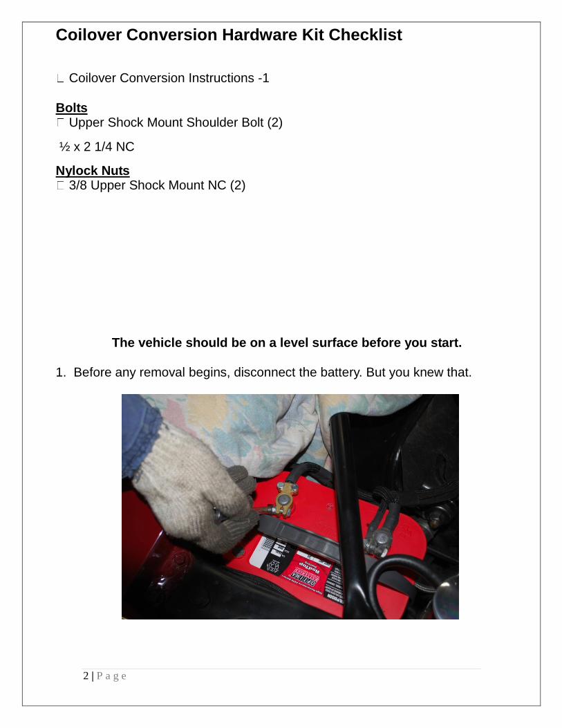
1. Before any removal begins, disconnect the battery. But you knew that.
3 | P a g e
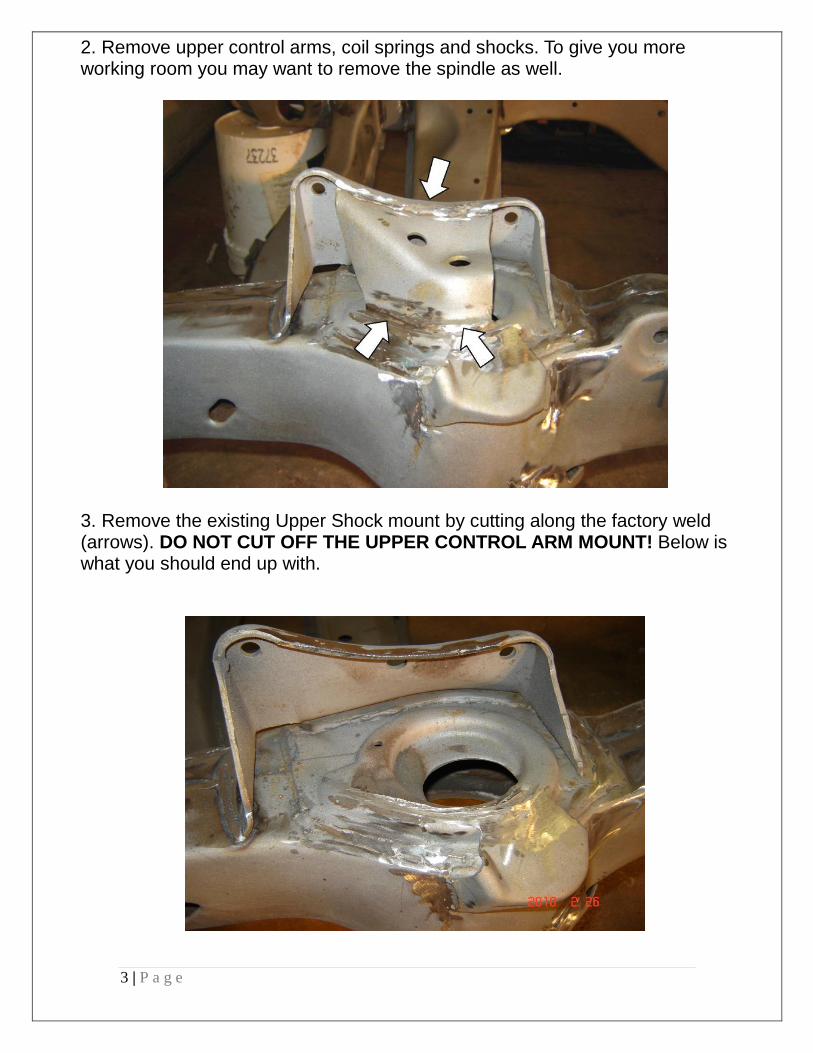
2. Remove upper control arms, coil springs and shocks. To give you more working room you may want to remove the spindle as well.
3. Remove the existing Upper Shock mount by cutting along the factory weld (arrows). DO NOT CUT OFF THE UPPER CONTROL ARM MOUNT! Below is what you should end up with.
4 | P a g e
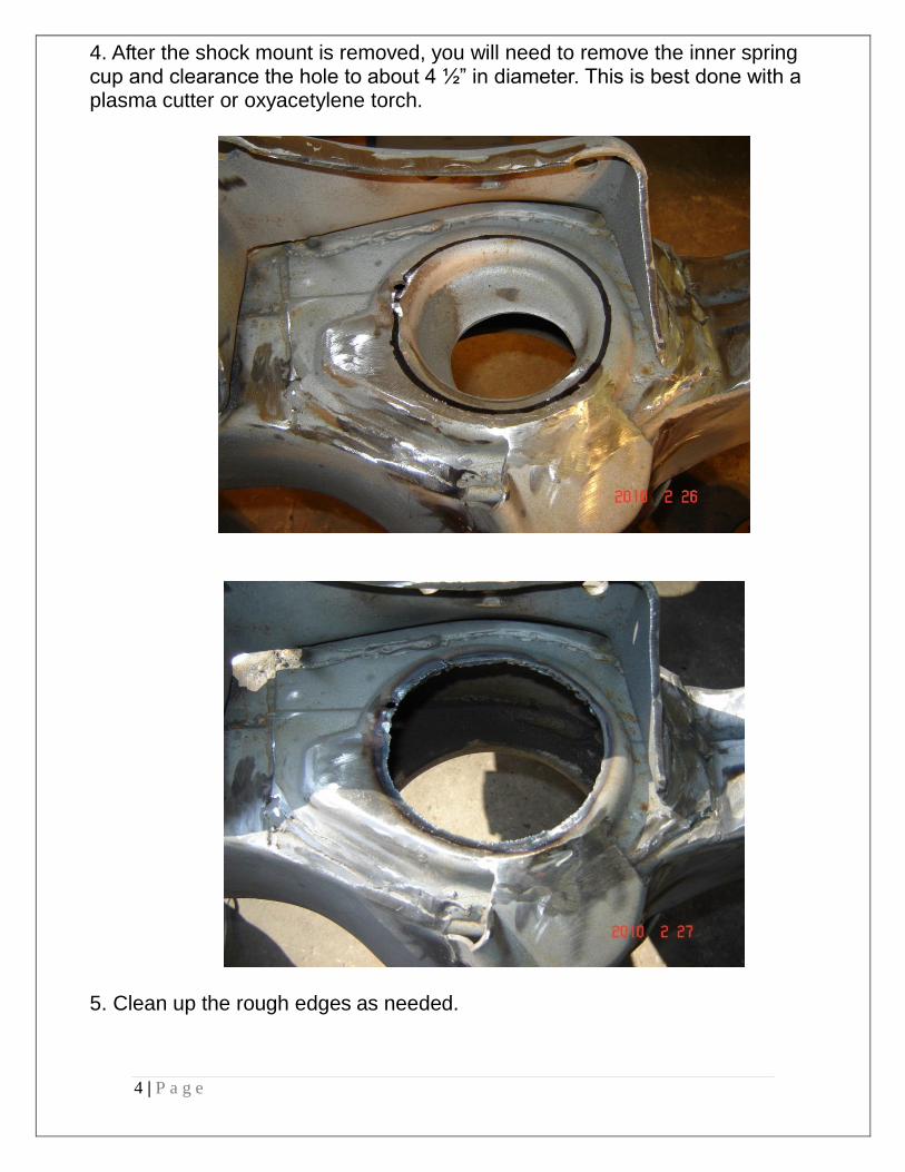
4. After the shock mount is removed, you will need to remove the inner spring cup and clearance the hole to about 4 ½” in diameter. This is best done with a plasma cutter or oxyacetylene torch.
5. Clean up the rough edges as needed.
5 | P a g e
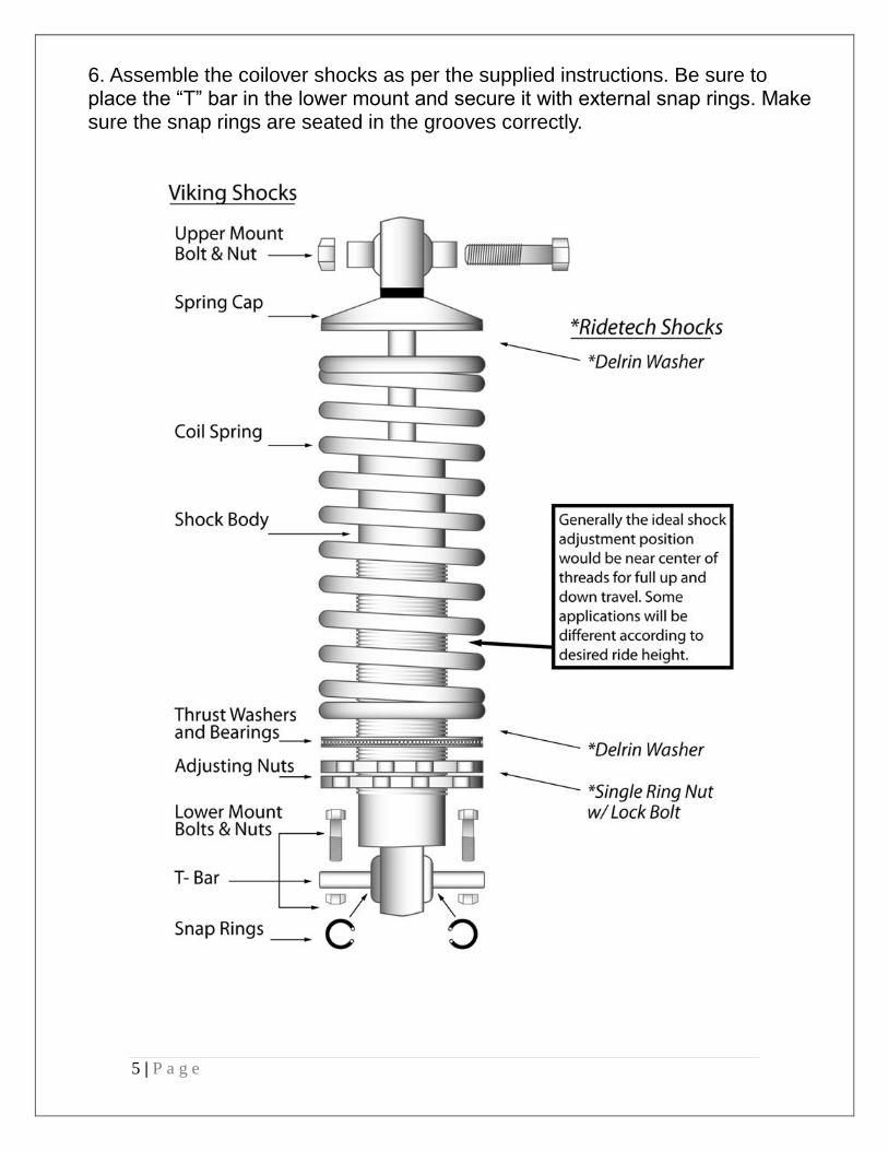
6. Assemble the coilover shocks as per the supplied instructions. Be sure to place the “T” bar in the lower mount and secure it with external snap rings. Make sure the snap rings are seated in the grooves correctly.
6 | P a g e
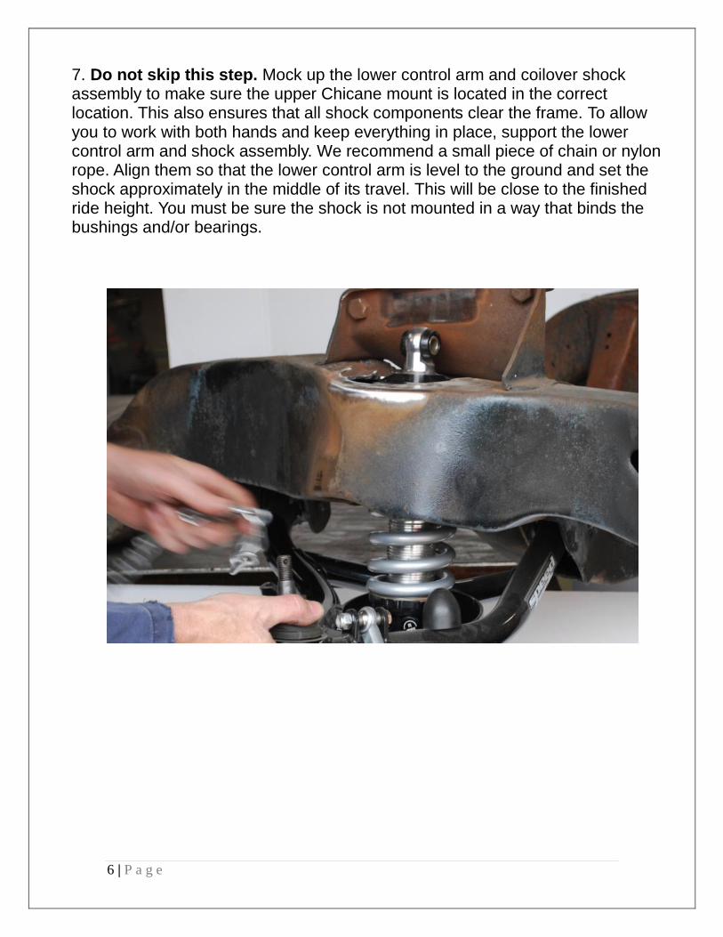
7. Do not skip this step. Mock up the lower control arm and coilover shock assembly to make sure the upper Chicane mount is located in the correct location. This also ensures that all shock components clear the frame. To allow you to work with both hands and keep everything in place, support the lower control arm and shock assembly. We recommend a small piece of chain or nylon rope. Align them so that the lower control arm is level to the ground and set the shock approximately in the middle of its travel. This will be close to the finished ride height. You must be sure the shock is not mounted in a way that binds the bushings and/or bearings.
7 | P a g e
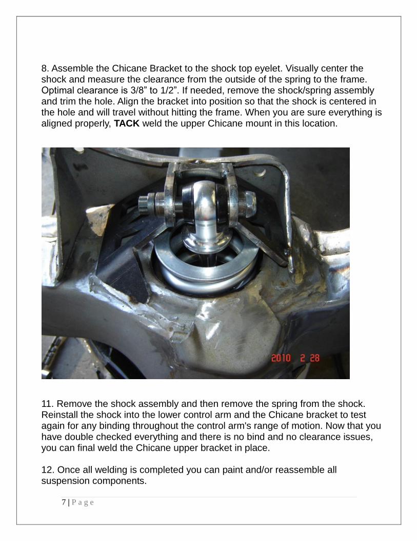
8. Assemble the Chicane Bracket to the shock top eyelet. Visually center the shock and measure the clearance from the outside of the spring to the frame. Optimal clearance is 3/8” to 1/2”. If needed, remove the shock/spring assembly and trim the hole. Align the bracket into position so that the shock is centered in the hole and will travel without hitting the frame. When you are sure everything is aligned properly, TACK weld the upper Chicane mount in this location.
11. Remove the shock assembly and then remove the spring from the shock. Reinstall the shock into the lower control arm and the Chicane bracket to test again for any binding throughout the control arm's range of motion. Now that you have double checked everything and there is no bind and no clearance issues, you can final weld the Chicane upper bracket in place. 12. Once all welding is completed you can paint and/or reassemble all suspension components.
8 | P a g e
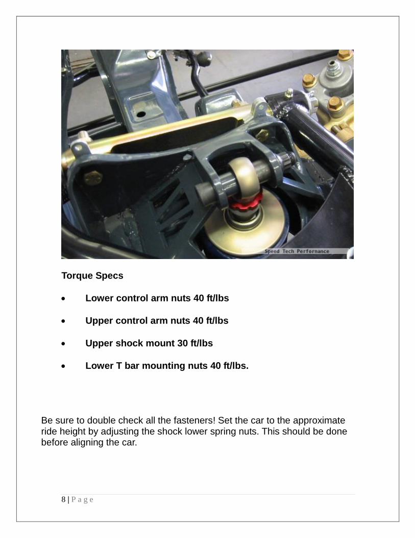
Torque Specs
Lower control arm nuts 40 ft/lbs
Upper control arm nuts 40 ft/lbs
Upper shock mount 30 ft/lbs
Lower T bar mounting nuts 40 ft/lbs.
Be sure to double check all the fasteners! Set the car to the approximate ride height by adjusting the shock lower spring nuts. This should be done before aligning the car.
9 | P a g e
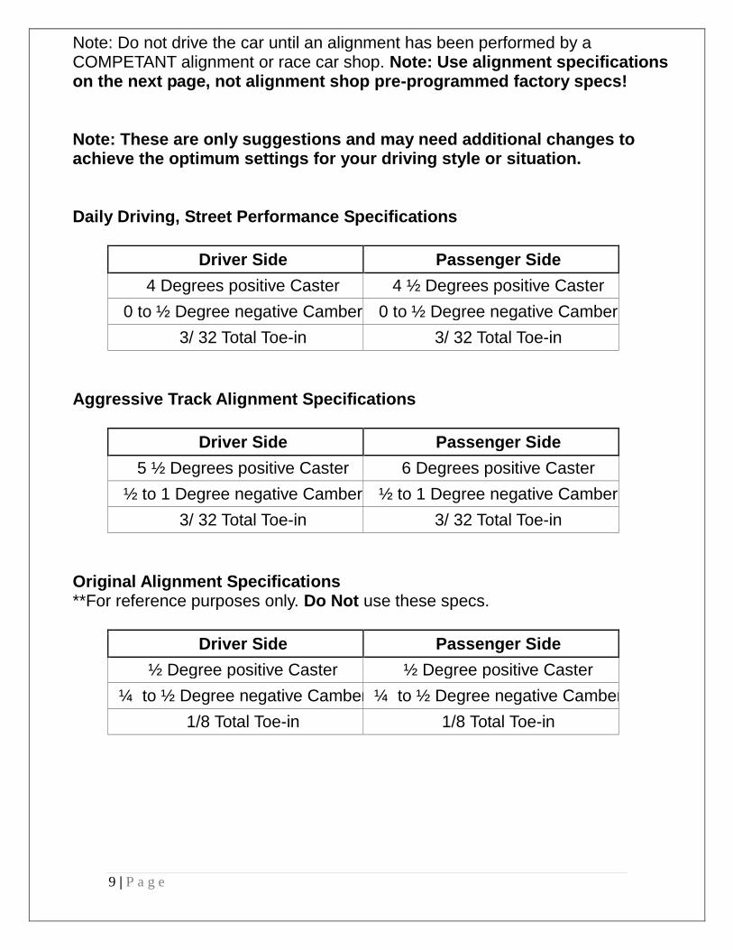
Note: Do not drive the car until an alignment has been performed by a COMPETANT alignment or race car shop. Note: Use alignment specifications on the next page, not alignment shop pre-programmed factory specs! Note: These are only suggestions and may need additional changes to achieve the optimum settings for your driving style or situation. Daily Driving, Street Performance Specifications
Driver Side Passenger Side
4 Degrees positive Caster 4 ½ Degrees positive Caster
0 to ½ Degree negative Camber 0 to ½ Degree negative Camber
3/ 32 Total Toe-in 3/ 32 Total Toe-in
Aggressive Track Alignment Specifications
Driver Side Passenger Side
5 ½ Degrees positive Caster 6 Degrees positive Caster
½ to 1 Degree negative Camber ½ to 1 Degree negative Camber
3/ 32 Total Toe-in 3/ 32 Total Toe-in
Original Alignment Specifications **For reference purposes only. Do Not use these specs.
Driver Side Passenger Side
½ Degree positive Caster ½ Degree positive Caster
¼ to ½ Degree negative Camber ¼ to ½ Degree negative Camber
1/8 Total Toe-in 1/8 Total Toe-in

10 | P a g e
Speedtech Performance USA LLC 3884 S River Rd, Bldg A
St George, UT 84770
435-628-4300 speedtechperformance.com
11 | P a g e
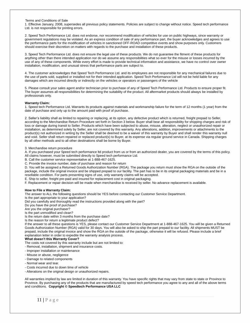
Terms and Conditions of Sale 1. Effective January, 2008, supersedes all previous policy statements. Policies are subject to change without notice. Speed tech performance Ltd. is not responsible for printing errors. 2. Speed Tech Performance Ltd. does not endorse, nor recommend modification of vehicles for use on public highways, since warranty or government regulations may be violated. As an express condition of sale of any performance part, the buyer acknowledges and agrees to use the performance parts for the modification of vehicles in sanctioned OFF-ROAD competitive events and show purposes only. Customers should exercise their discretion on matters with regards to the purchase and installation of these products. 3. Speed Tech Performance Ltd. does not ensure the legal use of these products. We do not guarantee the fitment of these products for anything other than there intended application nor do we assume any responsibilities what so ever for the misuse or losses incurred by the use of any of these components. While every effort is made to provide technical information and assistance, we have no control over owner installation, modification, and unusual stress that performance parts are subject to. 4. The customer acknowledges that Speed Tech Performance Ltd. and its employees are not responsible for any mechanical failures due to the use of parts sold, supplied or installed not for their intended application. Speed Tech Performance Ltd will not be held liable for any damages which are incurred directly or indirectly on the vehicles or operators or passengers of the vehicle 5. Please consult your sales agent and/or technician prior to purchase of any of Speed Tech Performance Ltd. Products to ensure proper fit. The buyer assumes all responsibilities for determining the suitability of the product. All aftermarket products should always be installed by professionals only. Warranty Claim: 1. Speed tech Performance Ltd. Warrants its products against materials and workmanship failure for the term of 12 months (1 year) from the date of purchase and only up to the amount paid with proof of purchase. 2. Seller’s liability shall as limited to repairing or replacing, at its option, any defective product which is returned, freight prepaid to Seller, according to the Merchandise Return Procedure set forth in Section 3 below. Buyer shall bear all responsibility for shipping charges and risk of loss or damage during transit to Seller. Products which have been subjected to abuse, misuse, alteration, neglect or unauthorized repair or installation, as determined solely by Seller, are not covered by this warranty. Any alterations, addition, improvements or attachments to the product(s) not authorized in writing by the Seller shall be deemed to be a waiver of this warranty by Buyer and shall render this warranty null and void. Seller shall return repaired or replaced product(s) to Buyer, at its expense via regular ground service in Canada. Shipping charges by all other methods and to all other destinations shall be borne by Buyer. 3. Merchandise return procedure A. If you purchased your Speed tech performance ltd product from us or from an authorized dealer, you are covered by the terms of this policy. All claims however, must be submitted directly to Speed tech performance Ltd.
B. Call the customer service representative at 1-888-467-1625.
C. Provide the invoice number, date of purchase and reason for return
D. You will be assigned a Returned Goods Authorization Number (RGA). The package you return must show the RGA on the outside of the package, include the original invoice and be shipped prepaid to our facility. The part has to be in its original packaging materials and be in a resellable condition. For parts presenting signs of use, only warranty claims will be accepted.
E. Ship to seller, freight pre-paid and insured for replacement cost in original packaging.
F. Replacement or repair decision will be made when merchandise is received by seller. No advance replacement is available. How to File a Warranty Claim: The answer to ALL the following questions should be YES before contacting our Customer Service Department. Is the part appropriate to your application? Did you carefully and thoroughly read the instructions provided along with the part? Do you have the proof of purchase? Are you the original purchaser? Is the part unmodified and clean? Is the return date within 3 months from the purchase date? Is the reason for return a legitimate product defect? If the answer to all these questions is YES, please contact our Customer Service Department at 1-888-467-1625. You will be given a Returned Goods Authorization Number (RGA) valid for 30 days. You will also be asked to ship the part prepaid to our facility. All shipments MUST be prepaid, include the original invoice and show the RGA on the outside of the package, otherwise it will be refused. Please include a brief explanation letter in order to expedite the warranty analysis process. What doesn’t this Warranty Cover? The costs not covered by this warranty include but are not limited to: - Removal, installation, shipment and insurance costs.
- Improper installation or maintenance
- Misuse or abuse, negligence
- Damage to related components
- Normal wear and tear.
- Costs incurred due to down time of vehicle
- Alterations on the original design or unauthorized repairs. All warranties implied by law are limited in duration of this warranty. You have specific rights that may vary from state to state or Province to Province. By purchasing any of the products that are manufactured by speed tech performance you agree to any and all of the above terms and conditions. Copyright © Speedtech Performance USA LLC

12 | P a g e
This page intentionally left blank